Focusing of radially and azimuthally polarized beams through a uniaxial crystal
4
Focusing of radially and azimuthally polarized beams through a uniaxial crystal Kazuhiro Yonezawa, Yuichi Kozawa, and Shunichi Sato* Institute of Multidisciplinary Research for Advanced Materials, Tohoku University, Katahira 2-1-1, Aoba-ku, Sendai 980-8577, Japan * Corresponding author: [email protected] Received April 23, 2007; revised November 29, 2007; accepted December 16, 2007; posted December 19, 2007 (Doc. ID 82303); published January 29, 2008 We calculated and measured the difference between focal positions of radially and azimuthally polarized beams after passing through a uniaxial crystal. Calculations were carried out on the basis of the ray optics and the vector diffraction theory. The results of the calculations were in good agreement with those of the experi- ment. In addition, we discussed the polarization selection in a hemispherical laser cavity that was used for the generation of a radially polarized beam by use of the birefringence of a c-cut Nd:YVO 4 laser crystal [Opt. Lett. 31, 2151 (2006)]. The stability range of the laser cavity length for the generation of a radially polarized beam was also in good agreement with the differences mentioned above. © 2008 Optical Society of America OCIS codes: 260.5430, 260.1440, 140.3580, 080.2720, 260.0260. 1. INTRODUCTION Recently, light propagation in birefringent material has attracted much attention, and theoretical studies have been performed [1–3]. For instance, focusing properties of incident laser beams in materials with small birefrin- gence have been investigated for objective lenses with high numerical aperture, because the birefringence in materials used for optical disks affects the performance of optical data storage system [4,5]. Intensity distributions near focus in uniaxial materials with different directions of the c axis have been calculated [6]. Thermally induced birefringence in a laser cavity due to the pumping of laser material, which results in the generation of two foci cor- responding to ordinary and extraordinary rays, have been investigated [7]. At the same time, recent progress with cylindrical vec- tor beams is stimulating theoretical and experimental studies. Calculations based on the vector diffraction theory have indicated the existence of a strong axial elec- tric field near focus when a radially polarized beam is tightly focused [8]. A radial and azimuthal polarizer was proposed, since calculations showed a remarkable differ- ence between the focal positions for radially and azimuth- ally polarized components of a beam after it passed through a birefringent plate [9]. In this calculation, objec- tives with large numerical apertures (0.9 and 0.45) were assumed, but a detailed description of the method, espe- cially with respect to the polarization distribution of an incident laser beam and the expression for the aberration function, has not been presented, as far as we know. Recently, we demonstrated the generation of a radially polarized laser beam directly from a hemispherical laser cavity by use of the birefringence of a c-cut Nd:YVO 4 crystal [10]. Although the polarization selection observed might be attributed to the difference between the focal po- sitions of radially and azimuthally polarized beams in- duced by the birefringence of the laser crystal itself, as far as we know, quantitative explanation has not been pre- sented. If the difference between the focal positions is much longer than the fluctuation of the cavity length due to mechanical noise and thermal expansion, the radially polarized beam will be stable. Thus, quantitative estima- tion of the stability range of the laser cavity for a radially polarized beam is important for evaluating the potential of the laser with a c-cut crystal as a laser source with ra- dial polarization. Because the beam convergence in a la- ser cavity is generally small, calculation of focal positions based on the ray optics might be applicable. However, cal- culation based on the vector diffraction theory is also nec- essary for verification of the effectiveness of the ray optics. In this paper, we calculated the focal positions of radi- ally and azimuthally polarized beams after passing through a uniaxial, c-cut Nd:YVO 4 crystal based on the ray optics and the vector diffraction theory, introducing a specific expression for the aberration function. Measured focal positions were in good agreement with those ob- tained by calculations. Furthermore, the stability range for the radially polarized laser beam was measured for ac- tual laser cavity, and this result was also in good agree- ment with the results obtained for the focal positions. 2. CALCULATIONS To calculate the focal positions for radially and azimuth- ally polarized beams after passing through a c-cut bire- fringent crystal, we apply two methods, the ray optics and the vector diffraction theory. The ray optics can provide a simple analytic solution if the incident angle is small. Ac- tually, because the converging angle in a laser cavity is generally small, the ray optics might be a useful tool to estimate focal positions. However, confirmation by using the vector diffraction theory is important because the ray optics is an approximation, and a more accurate result Yonezawa et al. Vol. 25, No. 2/February 2008/J. Opt. Soc. Am. A 469 1084-7529/08/020469-4/$15.00 © 2008 Optical Society of America
Transcript of Focusing of radially and azimuthally polarized beams through a uniaxial crystal

1Rabighmonobmri
tstttpeattacif
pccmsd
Yonezawa et al. Vol. 25, No. 2 /February 2008 /J. Opt. Soc. Am. A 469
Focusing of radially and azimuthally polarizedbeams through a uniaxial crystal
Kazuhiro Yonezawa, Yuichi Kozawa, and Shunichi Sato*
Institute of Multidisciplinary Research for Advanced Materials, Tohoku University,Katahira 2-1-1, Aoba-ku, Sendai 980-8577, Japan*Corresponding author: [email protected]
Received April 23, 2007; revised November 29, 2007; accepted December 16, 2007;posted December 19, 2007 (Doc. ID 82303); published January 29, 2008
We calculated and measured the difference between focal positions of radially and azimuthally polarizedbeams after passing through a uniaxial crystal. Calculations were carried out on the basis of the ray optics andthe vector diffraction theory. The results of the calculations were in good agreement with those of the experi-ment. In addition, we discussed the polarization selection in a hemispherical laser cavity that was used for thegeneration of a radially polarized beam by use of the birefringence of a c-cut Nd:YVO4 laser crystal [Opt. Lett.31, 2151 (2006)]. The stability range of the laser cavity length for the generation of a radially polarized beamwas also in good agreement with the differences mentioned above. © 2008 Optical Society of America
OCIS codes: 260.5430, 260.1440, 140.3580, 080.2720, 260.0260.
asmtptpodsbceo
atrsftftm
2Taftstgeto
. INTRODUCTIONecently, light propagation in birefringent material hasttracted much attention, and theoretical studies haveeen performed [1–3]. For instance, focusing properties ofncident laser beams in materials with small birefrin-ence have been investigated for objective lenses withigh numerical aperture, because the birefringence inaterials used for optical disks affects the performance of
ptical data storage system [4,5]. Intensity distributionsear focus in uniaxial materials with different directionsf the c axis have been calculated [6]. Thermally inducedirefringence in a laser cavity due to the pumping of laseraterial, which results in the generation of two foci cor-
esponding to ordinary and extraordinary rays, have beennvestigated [7].
At the same time, recent progress with cylindrical vec-or beams is stimulating theoretical and experimentaltudies. Calculations based on the vector diffractionheory have indicated the existence of a strong axial elec-ric field near focus when a radially polarized beam isightly focused [8]. A radial and azimuthal polarizer wasroposed, since calculations showed a remarkable differ-nce between the focal positions for radially and azimuth-lly polarized components of a beam after it passedhrough a birefringent plate [9]. In this calculation, objec-ives with large numerical apertures (0.9 and 0.45) weressumed, but a detailed description of the method, espe-ially with respect to the polarization distribution of anncident laser beam and the expression for the aberrationunction, has not been presented, as far as we know.
Recently, we demonstrated the generation of a radiallyolarized laser beam directly from a hemispherical laseravity by use of the birefringence of a c-cut Nd:YVO4rystal [10]. Although the polarization selection observedight be attributed to the difference between the focal po-
itions of radially and azimuthally polarized beams in-uced by the birefringence of the laser crystal itself, as far
1084-7529/08/020469-4/$15.00 © 2
s we know, quantitative explanation has not been pre-ented. If the difference between the focal positions isuch longer than the fluctuation of the cavity length due
o mechanical noise and thermal expansion, the radiallyolarized beam will be stable. Thus, quantitative estima-ion of the stability range of the laser cavity for a radiallyolarized beam is important for evaluating the potentialf the laser with a c-cut crystal as a laser source with ra-ial polarization. Because the beam convergence in a la-er cavity is generally small, calculation of focal positionsased on the ray optics might be applicable. However, cal-ulation based on the vector diffraction theory is also nec-ssary for verification of the effectiveness of the rayptics.
In this paper, we calculated the focal positions of radi-lly and azimuthally polarized beams after passinghrough a uniaxial, c-cut Nd:YVO4 crystal based on theay optics and the vector diffraction theory, introducing apecific expression for the aberration function. Measuredocal positions were in good agreement with those ob-ained by calculations. Furthermore, the stability rangeor the radially polarized laser beam was measured for ac-ual laser cavity, and this result was also in good agree-ent with the results obtained for the focal positions.
. CALCULATIONSo calculate the focal positions for radially and azimuth-lly polarized beams after passing through a c-cut bire-ringent crystal, we apply two methods, the ray optics andhe vector diffraction theory. The ray optics can provide aimple analytic solution if the incident angle is small. Ac-ually, because the converging angle in a laser cavity isenerally small, the ray optics might be a useful tool tostimate focal positions. However, confirmation by usinghe vector diffraction theory is important because the rayptics is an approximation, and a more accurate result
008 Optical Society of America
ct
ATtttTdgtaibtprSfIpft=d1dttscw=ttp
0wtni
BNobsrbBaat
watabvnctcip
widp
wpTd
Fitawotp
470 J. Opt. Soc. Am. A/Vol. 25, No. 2 /February 2008 Yonezawa et al.
an be provided by the vector diffraction theory, whichakes account diffraction and polarization effects.
. Ray Opticshe refraction of ordinary and extraordinary rayshrough a slab is depicted in Fig. 1. A ray is incident onhe left surface of the slab at an angle �. The direction ofhe c axis of the slab is perpendicular to the slab surface.he polarization direction of an ordinary ray is perpen-icular to the principal plane that is parallel to the propa-ation direction of the wavefront and the c axis. Becausehe optical system is cylindrically symmetric around the cxis, the ordinary rays form a beam whose polarization isn the azimuthal direction in the beam cross section. Thiseam corresponds to an azimuthally polarized beam. Onhe other hand, the extraordinary rays are parallel to therincipal plane and form a radially polarized beam. Theefraction angle �o for an ordinary ray is determined bynell’s law, n1 sin �=n2 sin �o, where n1 and n2 are the re-
ractive indices of atmosphere and the slab, respectively.n contrast, the refraction of an extraordinary ray is com-licated because the direction of the wave normal is dif-erent from that of the Poynting vector. The direction ofhe wave normal is determined by Snell’s law, n1 sin �nex sin �e, where nex is the refractive index of the extraor-inary ray at an angle �e. This angle is deduced from/nex
2 =cos2 �e /no2+sin2 �e /ne
2, where no and ne are the or-inary and the extraordinary refractive indices respec-ively, of the slab. The angle �ex between the direction ofhe Poynting vector and the c axis of the slab is repre-ented by the equation, ne
2 tan �ex=no2 tan �e. When the in-
ident angle is small, displacements of the crossing pointith a line parallel to the c axis due to the slab are doD�1−n1 /no� and de=D�1−n1no /ne
2� for ordinary and ex-raordinary rays, respectively, where D is the thickness ofhe slab. Thus, the difference between do and de is inde-endent of the incident angle and is calculated to be
ig. 1. (Color online) Schematic of the propagation of rays pass-ng through a birefringent slab whose c axis is perpendicular tohe slab surface. Dashed–dotted lines correspond to the path ofn ordinary ray. Dotted lines and dashed lines correspond to theave normal and the Poynting vector, respectively. The thicknessf the slab is D. The polarization directions of the ordinary andhe extraordinary rays are perpendicular and parallel to the pa-er, respectively.
.0934D in air. Here no and ne for a YVO4 crystal at aavelength of 1.064 �m are 1.9573 and 2.1652, respec-
ively. This means that the focal point of the extraordi-ary ray shifts from that of the ordinary ray by 1.40 mm
n the case of a YVO4 slab of 15 mm thickness.
. Vector Diffraction Theoryext, we calculate the intensity distributions near focus
f the converging radially and azimuthally polarizedeams to verify the validity of the simple estimation de-cribed above; the position of the focal point can be accu-ately estimated by wave theory. The calculation is doney using the formalism proposed by Youngworth andrown [8], following the vector diffraction theory by Rich-rds and Wolf [11]. The radial component Er�r ,z� and thezimuthal component Ea�r ,z� in the focal region are writ-en as
Er�r,z� = A�0
�
cos1/2���sin�2��l0���J1�kr sin ��
�exp�ikz cos ��d�, �1�
Ea�r,z� = 2A�0
�
cos1/2���sin �l0���J1�kr sin ��
�exp�ikz cos ��d�, �2�
here A is the relative amplitude, � is the maximumngle of the incoming ray, l0��� is the complex pupil func-ion, J1 is the first-order Bessel function of the first kind,nd k is the wavenumber. Because we will deal with aeam inside a laser cavity where the angle of beam con-ergence is small, as shown in the next section, we can ig-ore the longitudinal electric field component, which be-omes dominant only when a radially polarized beam isightly focused. In this calculation, we assume that the in-oming beam consists of plane waves and the distributions uniform. Therefore, the complex pupil function is ex-ressed as
l0��� = exp�ik�����, �3�
here ���� is the phase factor indicating the aberrationntroduced by a uniaxial slab. The phase factor for the or-inary wave,�o���, for a single slab of thickness D is ex-ressed as
�o��� = �noab + bc� − ad = D� no
cos �o+ sin ��tan � − tan �o�
−1
cos �� = D�no cos �o − cos ��, �4�
here, xy (x ,y=a, b, c, or d) is the distance betweenoints x and y as shown in Fig. 1, and we assume n1=1.he phase factor for the extraordinary wave,�e���, is de-uced in the same way as
Nbwcmt[ac
smst6tttsltv
3APaFmpawibtptW�attlni9mstbtrelri2bid
sptplttms
Ffw1p
Fp
Yonezawa et al. Vol. 25, No. 2 /February 2008 /J. Opt. Soc. Am. A 471
�e��� = D�� cos2 �e
no2 +
sin2 �e
ne2 �−1/2
cos �e − cos �� . �5�
ote that the angle �ex is not included in this expression,ecause the vector diffraction theory deals with planeaves and needs information about phase variation in the
alculation. In fact, the phase factor along the wave nor-al as shown in Eq. (5) is exactly the same as that along
he Poynting vector [12]. Thus, in contrast to the work in9], we do not need to take account of the phase factorlong the Poynting vector, which is more complicated toalculate.
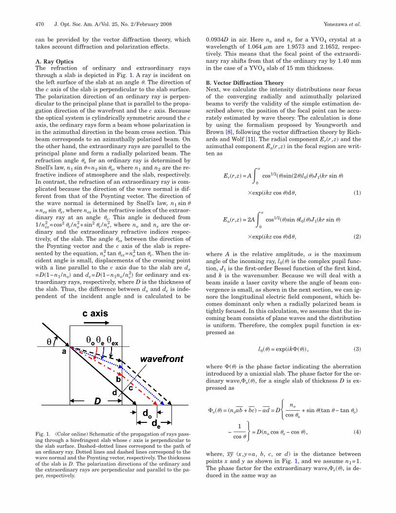
Figure 2 shows the results of calculation of the inten-ity distribution near focus of converging radially and azi-uthally polarized beams after passing through a YVO4
lab 15 mm long. The focusing condition is the same ashe experiment in the next section. The beam diameter ismm and the lens focal length is 250 mm. The origin of
he horizontal axis corresponds to the focal point whenhe slab is absent. Each broken white line corresponds tohe focal plane where the intensity is maximum. The po-itions of the focal plane for azimuthally and radially po-arized beams are 7.34 and 8.73 mm, respectively. Thus,he difference is 1.39 mm, which is close to the estimatedalue of 1.40 mm based on the ray optics.
ig. 2. (Color online) Calculated intensity distributions near theocus for beams (upper) with azimuthal polarization and (lower)ith radial polarization after passing through an YVO4 slab5 mm long. The horizontal axis indicates the distance from theoint corresponding to the focal point without the crystal.
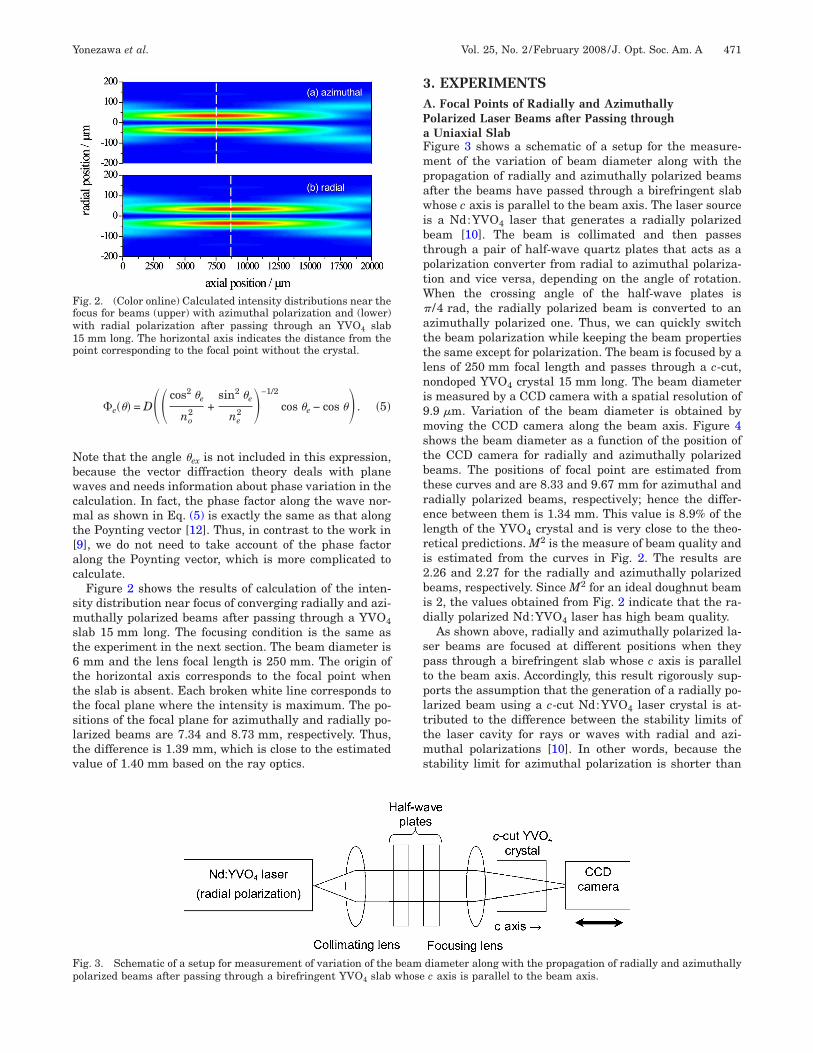
ig. 3. Schematic of a setup for measurement of variation of theolarized beams after passing through a birefringent YVO slab
4. EXPERIMENTS. Focal Points of Radially and Azimuthallyolarized Laser Beams after Passing throughUniaxial Slabigure 3 shows a schematic of a setup for the measure-ent of the variation of beam diameter along with the
ropagation of radially and azimuthally polarized beamsfter the beams have passed through a birefringent slabhose c axis is parallel to the beam axis. The laser source
s a Nd:YVO4 laser that generates a radially polarizedeam [10]. The beam is collimated and then passeshrough a pair of half-wave quartz plates that acts as aolarization converter from radial to azimuthal polariza-ion and vice versa, depending on the angle of rotation.
hen the crossing angle of the half-wave plates is/4 rad, the radially polarized beam is converted to anzimuthally polarized one. Thus, we can quickly switchhe beam polarization while keeping the beam propertieshe same except for polarization. The beam is focused by aens of 250 mm focal length and passes through a c-cut,ondoped YVO4 crystal 15 mm long. The beam diameter
s measured by a CCD camera with a spatial resolution of.9 �m. Variation of the beam diameter is obtained byoving the CCD camera along the beam axis. Figure 4
hows the beam diameter as a function of the position ofhe CCD camera for radially and azimuthally polarizedeams. The positions of focal point are estimated fromhese curves and are 8.33 and 9.67 mm for azimuthal andadially polarized beams, respectively; hence the differ-nce between them is 1.34 mm. This value is 8.9% of theength of the YVO4 crystal and is very close to the theo-etical predictions. M2 is the measure of beam quality ands estimated from the curves in Fig. 2. The results are.26 and 2.27 for the radially and azimuthally polarizedeams, respectively. Since M2 for an ideal doughnut beams 2, the values obtained from Fig. 2 indicate that the ra-ially polarized Nd:YVO4 laser has high beam quality.As shown above, radially and azimuthally polarized la-
er beams are focused at different positions when theyass through a birefringent slab whose c axis is parallelo the beam axis. Accordingly, this result rigorously sup-orts the assumption that the generation of a radially po-arized beam using a c-cut Nd:YVO4 laser crystal is at-ributed to the difference between the stability limits ofhe laser cavity for rays or waves with radial and azi-uthal polarizations [10]. In other words, because the
tability limit for azimuthal polarization is shorter than
diameter along with the propagation of radially and azimuthallyc axis is parallel to the beam axis.
beamwhose

tbc
BPIotrpimmirpstdttb
tirac
4Wdsutgwlbcfg
ATSt
R
1
1
1Fl
Ftd
472 J. Opt. Soc. Am. A/Vol. 25, No. 2 /February 2008 Yonezawa et al.
hat for radial polarization, only the radially polarizedeam is selectively generated by properly adjusting theavity length.
. Range of Cavity Length for Generating a Radiallyolarized Beamn this section, we will verify the discussion in the previ-us section. By changing the cavity length and checkinghe intensity distribution and the polarization state, theange of cavity length for selectively generating a radiallyolarized laser beam is measured. When the cavity lengths sufficiently short compared with the radius of the rear
irror �250 mm�, the laser beam is a Gaussian beam ofultitransverse mode. With decreasing cavity length, the
ntensity on the optical axis decreases and becomes zero,evealing a doughnut-mode beam. At this moment, theolarization of the beam is verified to be radial by mea-uring the intensity distribution of the laser beam afterhe beam passes through a linear polarizer. In fact, theistribution shows a two-lobe pattern and rotates withhe revolution of the polarizer. With further decrease ofhe cavity length, the radial polarization is maintainedut the output power decreases, as shown in Fig. 5. Here
ig. 5. Measured output power of a radially polarized Nd:YVO4aser as a function of the cavity length.
ig. 4. Measured beam diameter as a function of the position ofhe CCD camera. Rectangles and circles show the results for ra-ially and azimuthally polarized beams, respectively.
he position where the laser beam is verified to be radials set to zero. Thus, the range of the cavity length for aadially polarized beam is 1.35 mm. This value is in goodgreement with the values obtained above both theoreti-ally and experimentally.
. CONCLUSIONSe calculated the difference between focal positions of ra-
ially and azimuthally polarized converging beams with amall angle after the beams have passed through aniaxial crystal. The results of calculations based on bothhe ray optics and the vector diffraction theory were inood agreement with those of the experiment. In addition,e discussed the polarization selection in a hemispherical
aser cavity used for the generation of a radially polarizedeam by use of the birefringence of a Nd:YVO4 c-cut laserrystal [10]. The stability range of the laser cavity lengthor the generation of a radially polarized beam was also inood agreement with the differences obtained above.
CKNOWLEDGMENThis work was partially supported by the Grant-in-Aid forcientific Research (B) by the Ministry of Education, Cul-ure, Sport, Science, and Technology (MEXT) of Japan.
EFERENCES1. J. A. Fleck, Jr. and M. D. Feit, “Beam propagation in
uniaxial anisotropic media,” J. Opt. Soc. Am. 73, 920–926(1983).
2. G. S. Sithambaranathan and J. J. Stamnes, “Transmissionof a Gaussian beam into a biaxial crystal,” J. Opt. Soc. Am.A 18, 1670–1677 (2001).
3. A. Caittoni, G. Cincotti, and C. Palma, “Propagation ofcylindrically symmetric fields in uniaxial crystals,” J. Opt.Soc. Am. A 19, 792–796 (2002).
4. B. E. Bernacki and M. Mansuripur, “Investigation ofsubstrate birefringence effects on optical disk-performance,” Appl. Opt. 32, 6547–6555 (1993).
5. S. Stallinga, “Axial birefringence in high-numerical-aperture optical systems and the light distribution close tofocus,” J. Opt. Soc. Am. A 18, 2846–2859 (2001).
6. M. Jain, J. K. Lotsberg, and J. J. Stamnes, “Comparisons ofexact and paraxial intensities of electromagnetic wavesfocused into uniaxial crystals,” J. Opt. A, Pure Appl. Opt. 8,709–719 (2006).
7. I. Moshe and S. Jackel, “Influence of birefringence-inducedbifocusing on optical beams,” J. Opt. Soc. Am. B 22,1228–1235 (2005).
8. K. S. Youngworth and T. G. Brown, “Focusing of highnumerical aperture cylindrical vector beams,” Opt. Express7, 77–87 (2000).
9. M. Erdélyi and Z. Bor, “Radial and azimuthal polarizers,”J. Opt. A, Pure Appl. Opt. 8, 737–742 (2006).
0. K. Yonezawa, Y. Kozawa, and S. Sato, “Generation of aradially polarized laser beam by use of the birefringence ofa c-cut Nd:YVO4 crystal,” Opt. Lett. 31, 2151–2153 (2006).
1. B. Richards and E. Wolf, “Electromagnetic diffraction inoptical systems. II. Structure of the image field in anaplanatic system,” Proc. R. Soc. London, Ser. A 253,358–379 (1959).
2. M. Avendaño-Alejo and M. Rosete-Aguilar, “Optical pathdifference in a plane-parallel uniaxial plate,” J. Opt. Soc.
Am. A 23, 926–932 (2006).


![Research Article Partially Coherent, Radially Polarized ...combination [ , ]inthelastfewyears.Inthispaper, we investigate the tight focusing properties of amplitude modulated radially](https://static.fdocuments.us/doc/165x107/61037d2c0512f42469372c46/research-article-partially-coherent-radially-polarized-combination-inthelastfewyearsinthispaper.jpg)