Focus on Membrane Technology for Water Treatment Problem Membrane Technology for Water Treatment...
74
Focus on Membrane Technology for Focus on Membrane Technology for Water Treatment Water Treatment Toray Industries, Inc. Masaru Kurihara February 4, 2004
Transcript of Focus on Membrane Technology for Water Treatment Problem Membrane Technology for Water Treatment...

Focus on Membrane Technology for Focus on Membrane Technology for Water TreatmentWater Treatment
Toray Industries, Inc.Masaru KuriharaFebruary 4, 2004

CONTENTCONTENT
1. World Water Problem1. World Water Problem
2. Water Treatment Membranes2. Water Treatment Membranes
3. RO Membranes & NF Membranes3. RO Membranes & NF Membranes
4. UF Membranes & MF Membranes4. UF Membranes & MF Membranes-- Drinking Water Production Drinking Water Production --
5. Immersed Membranes5. Immersed Membranesfor Wastewater Treatmentfor Wastewater Treatment
6. Conclusion6. Conclusion

Toray Toray –– The Leader in The Leader in ““Advanced MaterialsAdvanced Materials””
Achieving High Growth by Constantly Supplying “Advanced Materials” – Developed with our Core Technologies – into our Three Growth Areas (an expansion of our four strategic business areas)
IT-related Products
EnvironmentSafety
Amenity
Life Sciences
<Three Growth Areas>•Nanofibers•High-performance Fibersand Resins
•Nano-alloy Materials•Advanced ElectronicsMaterials
•Biomaterials•Separation Materials•High-performance CompositeMaterials
•Recycling Materials
Organic SyntheticChemistry
Polymer Chemistry
Biochemistry
Four Strategic Business Areas
Carbon Fiber
Electronics & Info-
Related Products
Water Treatment
Pharmaceuticals
<Advanced Materials>
<Core Technologies>
Achieving High Growth by Constantly Supplying “Advanced Materials” – Developed with our Core Technologies – into our Three Growth Areas (an expansion of our four strategic business areas)

World Water Shortage World Water Shortage -- Now and FutureNow and Future (WMO and others, 1996) (WMO and others, 1996)
1995
2025
≧40%40~20%20~10%≦10%
Water Shortage
Main regions which have high water shortage percentages of more than 20%
2025:
1) ≧40% : Middle East, Korea, Pakistan, India, Algeria, South Africa, etc.
2) 20~40%: Mexico, China, USA, Europe (excluding UK)
1995:
1) ≧40% :Middle East, Singapore, Korea, Pakistan
2) 20~40%: India, Mexico, Europe (excluding UK and France), Taiwan, South Africa
Water shortage presumed to continue worldwide especially in Europe and the U.S.A., as well as throughout China by 2025
Water shortage presumed to continue worldwide especially in Europe and the U.S.A., as well as throughout China by 2025

Water Problem and Membrane TechnologyWater Problem and Membrane Technology
In operationIn operationProblemJapanIn operationIn operationIn operationSevereSingapore
PlanningBeing applied
Being appliedSevereProblemChinaConstructionIn operationSevereKuwait
PlanningIn operationSevereSaudi ArabiaBeing appliedIn operationBeing appliedProblemProblemSpainBeing appliedIn operationProblemUK, France
In operationBeing appliedProblemBenelux
ConstructionIn operationIn operationProblemProblemUnited States
Wastewater Reuse &
ReclamationDesalinationFresh Water
Treatment Water
Pollution
Water Resource Shortage
Membrane Technology for Water TreatmentWater Problem
Region, Country
Water resources are extending from fresh water to sea water & wastewater

Water Treatment MembranesWater Treatment Membranes

Membrane and Relative Size of Common MaterialsMembrane and Relative Size of Common Materials
Membrane
Relative SizeofCommonMaterials
0.0001 0.001 0.01 0.1 1 10Size (μm)
Cl- ionNa+ion
Pesticide, Organic Material
Zn2+ionF- ion
Pb2+ ionNO3
-ionTrihalomethane
Hepatitis A Virus
Polio VirusVirus
Influenza Virus Algae, Mad
Vibrio Cholerae
ColiformCryptosporidium
Bacillus anthracis
RO
NF
UFMF
Reverse Osmosis
Nanofiltration
MicrofiltrationUltrafiltration
ApplicationSea Water Desalination
Wastewater TreatmentDrinking Water
Drinking Water
Wastewater Treatment
Drinking Water
Brackish Water Desalination
Membrane
Relative SizeofCommonMaterials
0.0001 0.001 0.01 0.1 1 10Size (μm)Size (μm)
Cl- ionNa+ion
Pesticide, Organic Material
Zn2+ionF- ion
Pb2+ ionNO3
-ionTrihalomethane
Hepatitis A Virus
Polio VirusVirus
Influenza Virus Algae, Mad
Vibrio Cholerae
ColiformCryptosporidium
Bacillus anthracis
RO
NF
UFMF
Reverse Osmosis
Nanofiltration
MicrofiltrationUltrafiltration
ApplicationSea Water Desalination
Wastewater TreatmentDrinking Water
Drinking Water
Wastewater Treatment
Drinking Water
Brackish Water Desalination

Separation Characteristics of Various MembranesSeparation Characteristics of Various Membranes
UF/MF MembranesRO/NF Membranes
RO: <1 nm NF: 1~10 nm
Water
Monovalent ions
Low MW organic materials (Mw ≦200)
Membrane
UF: 10~100 nmMF: >100 nm
IonsDissolved matter
Suspended Solid Particles
Pore size
Separationmechanism
RO: Molecular interactionSolution diffusionElectric repulsion
NF: Size exclusion
MF: Dynamic separation
Size exclusion
UF: Electric repulsion
Permeationand
rejection
Middle to high MW materials (Mw >200)
Water
Membrane
Multivalent ions

Global Capacity of Membrane Filtration PlantsGlobal Capacity of Membrane Filtration Plants
0
0
0
0
0
0
0
5 6 7 8 9 0 2 3 4 5 6 7 8 9 0 2 3
Annual Total
Cumulative Total
Crypto outbreak
Contracted
Potential New
Cumulative Estimate
RO+NF
1985
1986
1987
1988
1989
1992
1991
1990
1995
1994
1993
1996
1997
1998
1999
2000
2001
2002
Inst
alle
d C
apac
ity (m
3 /d x
103 )
12,000
10,000
8,000
6,000
4,000
2,000
0
RO&NF Cumulative
Crypto outbreak
MF&UF Cumulative
MF&UF Annual
Contract
Potential New
Cumulative Estimated

( ) : in R & D
PAN hollow fiberUF membraneRiver
LakeGround
Drinkingwater
PVDF MF/UF flat sheet membrane for MBRSewage
&Ind.
Discharge
Drinkingwater
Low-fouling RO membrane
RO membranewith high boron removal Low cost
(=High recovery)
High quality (Low boron conc.)
Sea-water
RO membranefor brine conversion system
High qualityfor reuse and reclamation
Coagulation & Sedimentation
Securityconservation
Removal of cryptosporidium
NF membrane forscaling inhibition
Sand Filter
Sedimentation
MF/UFmembrane
MF/UF Membrane Bio-Reactor (MBR)
Low-foulingRO
Brine conversionTwo-stage SWRONF
NF
PVDF hollow fiberMF(UF) membrane
Des
alin
atio
nD
rink
ing
wat
erpr
oduc
tion
Was
tew
ater
tr
eatm
ent
New
New
New
Con
v.C
onve
ntio
nal
Con
v.
Drinkingwater
Single Stage SWRO
Multi stage flush (MSF)
Coagulation & Sedimentation
ActivatedSludge
Multi Stage Flush (MSF)
Water treatment processes Toray’s productsTechnical target
: New membrane productsMembrane applications Membrane applications -- Conventional Conventional && new technologiesnew technologies

TorayToray’’s Membranes & Applicationss Membranes & Applications
Feed water
RO membrane
Permeate carrier
Mesh spacer
Permeate
Brine seal
Permeate
Brine
Product tube
Feed water
1. RO & NF Membrane Romembra TM*
1) Seawater & Brackish Water Desalination
2) Ultra Pure Water Production
3) Harmful Material Removal
4) Wastewater Reuse
2. PAN Hollow Fiber UF Membrane Torayfil TM*
Φ114mm
1078mm1) Industrial Process Water Production
2) Drinking Water Production
3) Wastewater Reuse

TorayToray’’s Membranes & Applicationss Membranes & Applications
8 inches2m length
1) Drinking water production
3. PVDF Hollow Fiber MF MembraneTorayfil-F TM*
2) Industrial process water production
3) Pre-treatment for seawater desalination
4) Wastewater reuse
4. PVDF Flat Sheet MF Membranefor MBR
Element
Permeate
1) Municipal and industrial wastewater treatment
2) Municipal and industrial wastewater reuse

RO Membranes & NF MembranesRO Membranes & NF Membranes

Structure of RO Membrane ElementStructure of RO Membrane Element
Structure of RO Element
Center Tube
Brine Seal
Feed
Water
Feed Water
Permeate Permeate
Spacer
RO Membrane
Feed Water
Spacer
Brine
Water
Permeate
Center Tube
Brine Seal
Feed
Water
Feed Water
Permeate Permeate
Spacer
RO Membrane
Feed Water
Spacer
Brine
Water
Permeate
SubstratePolyester Taffta
150μm
Support Membrane
Polysulfone45μm
Separation MembraneCrosslinked Aromatic Polyamide
0.2μm
Filtrate
Feed
Structure of RO Membrane
Structure of Composite Membrane

Application of RO MembranesApplication of RO Membranes
Ultra Pure Water Industrial Process WaterRecovery of Valuables
1. Industrial
Pure Water for Boilers
Food Industry Process Water
3. WastewaterReuse & Reclamation
IndustryAgricultureIndirect Drinking
Water
Sea Water DesalinationBrackish Water Desalination
2. Drinking Water
RO Membranes

Water Production CostWater Production Cost
0
50
100
トー
タル
造水
コス
ト
(円
/m
3)
Sea Water Desalination
(MSF) Sea Water Desalination
(RO) Wastewater Reuse(MF + RO)
Ground waterSurface WaterTreatment (MF)
MSF (literature)
Singapore
136,000 (m3 /d) (2
001)
Kuwait
310,000 (m3 /d) (2
004)
Estimation
100,000 (m3 /d) (2
002)
Wat
er P
rodu
ctio
n C
ost (
yen/
m3 )
Water Resource can be Chosen by CountryWater Resource can be Chosen by Country

Progress of RO Seawater Desalination PlantsProgress of RO Seawater Desalination Plants
Recovery
Operational Pressure
Product Water Quality (TDS)
Energy Consumption
%
psig(MPa)
mg/l
kWh/kgal(kWh/m3)
1980‘s 1990‘s 2000‘s
25 40 - 50 55 - 65
1,000(6.9)
1,200(8.25)
1,400(9.7)
500 300 <200
45(12)
21(5.5)
17.4(4.6)
I. Moch, Pre-prints of ADA Conference in Lake Tahoe (2000)
Progress of Membrane Technology Realized Good Quality & Energy Saving
Progress of Membrane Technology Realized Good Quality & Energy Saving

Sea Water Desalination RO Membranes in Global MarketSea Water Desalination RO Membranes in Global Market
Asymmetric MembraneCellulose TriacetateHOLLOSEPToyoboHollow Fiber
NTR-SWCNitto Denko/Hydranautics
TFCL-HPKoch/Fluidosystems
SW-30Dow/Filmtech Composite
MembraneCrosslinkedAromatic Polyamide
SU-800Toray
Spiral
MorphologyMaterialProductSupplierModule Type
Crosslinked aromatic polyamide/spiral module is global standard. Toyobo is the only hollow fiber module supplier.DuPont withdrew from the hollow fiber RO module business in March 2001.
Crosslinked aromatic polyamide/spiral module is global standard. Toyobo is the only hollow fiber module supplier.DuPont withdrew from the hollow fiber RO module business in March 2001.

Technological Trends of RO/NF MembranesTechnological Trends of RO/NF MembranesUltra low Low High Ultra high
0.3 0.5 1.0 2.0 5.5 10.0
OperatingPressure[MPa]
Recovery = 40%
Recovery = 60%
Toxic mat. removalCost reduction
High TOC removalHigh qualityCost reduction
Notes
High TDS removalPressure durabilityHigh boron removal
Super low
High TDS removalHigh boron removal
Cost reductionLow-fouling
Ultr
apu
rew
ater
Lower pressure
Was
te
wat
erre
use Low-fouling
Cost reduction
N Co., D Co.
D Co., N Co., H Co.
N Co.
Pre-
Ttr
eat.
of
SWR
O Scale removal
Dri
nkin
gw
ater
Prod
uct.
D Co., N Co.
in R & D by Toray
N Co., H Co.
Rev
erse
osm
osis
Nan
ofilt
ratio
n 2n
dst
g.1s
t stg
.
SWR
OB
W RO
D Co. : Dow N Co. : Nitto Denko H Co.: Hydranautics

Progress of RO Membrane Performance Progress of RO Membrane Performance
Medium Low Pressure Ultra Low Super Ultra Low
1.0 0.50.71.52.0 0.83.05.0Operating Pressure(MPa/(m3/m2 day))
Flux (m3/m2 day MPa)
Controlling of Interfacial Polycondensation Reaction, and use of Catalyst
Ⅰ Ⅱ Ⅲ Ⅳ
NaC
l Rej
ectio
n (%
)
CA Asymmetric Membrane(1970's)
(1999)(1996)(1988)(1987)
Crosslinked Aromatic PA Composite Membrane
0 0.2 0.60.4 0.8 1.0 1.2 1.4 1.6 1.8 2.0
99.8
99.5
99.0
98.0
95.0
90.02.2
Crosslinked PA Composite Membrane
(1980's)
Changing of Material and/or Morphology of
Membrane
UTC-70 UTC-70L UTC-70U UTC-70UL
World’s No. 1 Membrane PerformanceWorld’s No. 1 Membrane Performance

Conventional OneConventional One--Stage RO Sea Water Desalination Stage RO Sea Water Desalination SystemSystem
Pretreatment
FeCl3
Chlorine H2SO4
RO Element
High Pressure PumpMotor
Brine
Pressure≦7MPa*)
CartridgeFilter
NaHSO3
Chlorine
Energy RecoveryTurbine
ProductWaterSea Water Sea Water Tank Feed Tank
*) Spiral element

Okinawa Sea Water Desalination PlantOkinawa Sea Water Desalination Plant(Capacity: (Capacity: 40,000 m40,000 m³³/d, 1996)/d, 1996)
RO Module Installation(each unit produces 5,000m³/d)
40,000m³/d: Tap water for 160,000 people
Toray Module is used in Japan’s Largest PlantToray Module is used in Japan’s Largest Plant

Largest Sea Water Desalination Plants in the WorldLargest Sea Water Desalination Plants in the World
RO sea water desalination seems very difficult in theArabian Gulf, because troubles occurred at all of DuPont’s RO plants. Al Jubail III is the first successful plant.
RO sea water desalination seems very difficult in theArabian Gulf, because troubles occurred at all of DuPont’s RO plants. Al Jubail III is the first successful plant.
* DuPont withdrew from RO business in 2001DuPont/TorayPWT200090,909Al Jubail IIISaudi Arabia11
HydraCOVANTA200394,625TampaUSA10
HydraABENS/ONDEO/PRI2001120,000CarbonerasSpain9
ToyoboMitsubishi1995128,000YanbuSaudi Arabia8
-IDE/ IL2004128,690HermosilloMexico7
(Toray)Hyflux2004136,000TuasSingapore5
TorayIonics2002136,000Point LisaTrinidad and Tobago5
TorayIonics2004137,000AshdodIsrael4
HydraONDEO2003170,000FujairahUAE3
TorayToray/ Mitsui/ Veolia2006227,300TaweelahUAE2
DowOTID/ IDE/ OTV2004272,520AshkelonIsrael1
Membrane Supplier
Plant SupplierOperation(year)
Capacity(m3/d)
LocationCountry

Typical Flow Diagram of Brine Conversion Two Stage RO Typical Flow Diagram of Brine Conversion Two Stage RO Seawater Desalination SystemSeawater Desalination System
( ): Water Flow Ratio
WaterRecovery
60%
BrineWater (60)
Product Water
(40)Seawater
(100)
High PressurePump
RO Element1st Stage
Conventional System
Pretreatment
6.5MPa
6.5 →9.0MPa
Brine Conversion Two Stage RO Seawater Desalination System
C=3.5% SW
C=5.8% SWRO Element
2nd Stage
Booster Pump Product Water (20)
BrineWater (40)C=8.8% SW
TotalProduct Water
(40+20)
Toray’s Patent: Japanese Patent Application 1994-245184(1994), US: 6187200(2001), CA: 216033(2001), RC:302294(1997), AU: 691649(1998), EU(granted 2002), KR: 204608(1999), Pending - JP, CH

Performance Trends of RO Membranes for Seawater Desalination Performance Trends of RO Membranes for Seawater Desalination Pr
essu
re R
esis
tanc
e L
evel
of R
O
Mem
bran
e E
lem
ents
(MPa
)
0 1
8.0
7.0
6.0
5.0
High Pressure Hollow Fiber CA
Membrane ( 1998)
Hollow Fiber PA Membrane
(1969)
High Pressure Hollow Fiber PA Membrane (1992)
Ultra High Pressure Spiral PA Composite Membrane
(Toray 1996)
35,000 mg/L Seawater
Spiral PA Composite Membrane (1978-1979)
Spiral PA Composite Membrane (1998)
World No. 1 Membrane Performance for Sea Water DesalinationWorld No. 1 Membrane Performance for Sea Water Desalination
10.0
9.0
0 20 30 40 50 60Water Recovery Ratio from 3.5% seawater (%)

Global Installations of Toray Sea Water Desalination Global Installations of Toray Sea Water Desalination ROsROs
●●
●
●
●
●
●●●
●
●
●
●●●●
●●
●
●
●
●
●
●
●
●●●●
●● ● ●● ●
●
●
●●
●● ●
●
●
●
●●
●
●
●●
●
●●
●
●
●
●
●●●
●
●
●
●●●●
●●
●
●
●
●
●
●
●
●●●●
●● ● ●● ●
●
●
●●
●● ●
●
●
●
●●
●
●
●●
●
● :Toray’s 2-Stage RO Systems● :Conventional RO Systems
Trinidad and Tobago136,000 (m3/d)
Mas Palomas(Spain Canary Island)
No. 1 Plant 4,500 (m3/d)
Mas Palomas(Spain Canary Islands)
No. 2, 3 Plant 9,000 (m3/d)
KAE Curacao(Netherlands Antilles)
11,400 (m3/d)Okinawa(Japan)
40,000 (m3/d)
Tortola(British Virgin Islands)
690 (m3/d)
Al Jubail(Saudi Arabia)91,000 (m3/d)

Results of MembraneResults of Membrane BiofoulingBiofouling (MBP) Assay(MBP) Assay
0.00
0.02
0.04
0.06
0.08
0.10
0.12
0.14B
/F
Rat
io
疎水性微生物(Mycobacteria)
親水性微生物(Flavobacteria)
Bad(High attachment)
RO Low-fouling RO
Standard level(Cellulose Acetate Membrane)
600nm
600nm
RO
Low-fouling RO
Fouling : Deterioration of membrane performance caused by stains
Good(Low attachment)
Bac
teria
l Atta
chm
ent (
B/F
ratio
)Surface
Surface
Cross section
Cross section
(Orange County water district: Dr.Ridgway)
Mycobacteria(hydrophobic cell surface)Flavobacteria(hydrophilic cell surface)
Toray less-fouling RO membrane has extremely low bacteria attachment
Toray less-fouling RO membrane has extremely low bacteria attachment

Wastewater Reclamation & Reuse PlantsWastewater Reclamation & Reuse PlantsRO
ReclamationReuse
MF DisinfectionsWastewater
Country Location Capacity Operation Plant Membrane (m3/d) Year Supplier Supplier
1 Kuwait Sulaibiya 300,000 2003 IONICS Toray2 USA CA Fountain Val 264,950 2004 PROJECT 3 Singapore Ulu Pandan 140,000 20044 India Chennai 135,000 1999 CAMP DRESSER 5 USA CA San Diego 75,0006 Spain Almeria 42,000 2001 PRIDESA/INIMA PERMETEC ES
7 Singapore Kranji 40,000 2003 Hydranautics8 Singapore Bedok 32,000 2003 Hydranautics9 Saudi Arabia Jeddah 30,000 1990 BIWATER GB DuPont 10 Korea 26,182 1996 IONICS US Dow/Filmtec 11 Singapore Seletar 24,000 2003 Toray
12 Japan 22,984 1983 KURITA JP Toray13 USA AZ Scottsdale 22,710 1998 ADVANCED ES USA Koch
VEOLIA HYFLUX
HYFLUX
(Nov. 2003 :Based on IDA Inventory Report 2002)
Toray less-fouling RO was selected at the world’s largest RO plantToray less-fouling RO was selected at the world’s largest RO plant
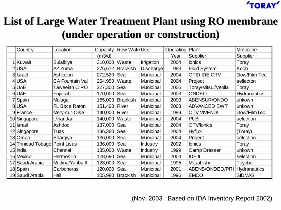
List of Large Water Treatment Plant using RO membrane List of Large Water Treatment Plant using RO membrane (under operation or construction)(under operation or construction)
Country Location Capacity Raw Wate User Operating Plant Mmbrane(m3/d) Year Supplier Supplier
1 Kuwait Sulaibiya 310,000 Waste Irrigation 2004 Ionics Toray2 USA AZ Yuma 276,672 Brackish Discharge 1983 Fluid System Koch3 Israel Ashkelon 272,520 Sea Municipal 2004 OTID IDE OTV Dow/Film Tec4 USA CA Fountain Val 264,950 Waste Municipal 2004 Project sellecton5 UAE Taweelah C RO 227,300 Sea Municipal 2006 Toray/Mitsui/Veolia Toray6 UAE Fujairah 170,000 Sea Municipal 2003 ONDEO Hydranautics7 Spain Malaga 165,000 Brackish Municipal 2003 ABENSUR/ONDO unkown8 USA FL Boca Raton 151,400 River Municipal 2003 ADVANCED EWT unkown9 France Mery-sur-Oise 140,000 River Municipal 1999 OTV VIVENDI Dow/FilmTec
10 Singapore Ulpandan 140,000 Waste Municipal 2004 PUB selection11 Israel Ashdod 137,000 Sea Municipal 2004 OTV/Ionics Toray12 Singapore Tuas 136,380 Sea Municipal 2004 Hyflux (Toray)13 Oman Sharqiya 136,000 Sea Municipal 2004 Project selection14 Trinidad Tobago Point Lisas 136,000 Sea Industry 2002 Ionics Toray15 India Chennai 135,000 Waste Industry 1999 Camp Dresser unkown16 Mexico Hermosillo 128,690 Sea Municipal 2004 IDE IL selection17 Saudi Arabia Medina/Yanbu II 128,000 Sea Municipal 1995 Mitsubishi Toyobo18 Spain Carboneras 120,000 Sea Municipal 2001 ABENS/ONDEO/PRI Hydranautics19 Saudi Arabia Hail 105,980 Brackish Municipal 1996 EMCO SIDMAS
(Nov. 2003 ; Based on IDA Inventory Report 2002)

Cumulative Installations of Toray Cumulative Installations of Toray ROsROs by Applicationby Application
198
7
1988
198
9
1990
199
1
199
2
199
3
199
4
199
5
199
6
1997
199
8
1999
2000
200
1
200
2
その他 13万m3/d海淡 65万m3/d
かん水 204万m3/d超純水 147万m3/d
0
500,000
1,000,000
1,500,000
2,000,000
2,500,000
累積
造水
量(m
3/日
)
年度
Cum
ulat
ive
Inst
alla
tion
(m3 /d
)
YearUltra pure water 1,470
(thousand m3/d)
Brackish water 2,940Sea water desalination 650
Others 13Global Extension
Wastewater reuse& reclamation
Ultra pure water productionBrackish water desalination Sea water desalination

Toray GroupToray Group’’s Business Bases and Global Operationss Business Bases and Global Operations
Ropur
●●
●
●
●
●
●
TMA
Flat Sheet Membrane Flat Sheet
Membrane
Toray
●
●
●
●
Flat Sheet Membrane ProductionElement ProductionThree Main
Base Structure

Conclusion Conclusion –– RORO••NF MembranesNF Membranes
1. The RO seawater desalination system has entered astable growth stage and the business is expanding steadily.
2. Wastewater reuse and reclamation is expected to be a new RO application.
3. Expansion of the NF membrane businesses is expected in the pretreatment of seawater desalination, and in highly efficient water purification systems.

UF Membranes & MF MembranesUF Membranes & MF Membranes-- Drinking Water Production Drinking Water Production --

UF & MF MembranesUF & MF Membranes –– Breakdown of World Applications Breakdown of World Applications --
Drinking Water WastewaterTreatment
Industrial Water
Ref: David H. Furukawa,WATERMARK, October 17, 2002
Others
Total Water Production: 4.9 million m3/d

Market for HollowMarket for Hollow--fiber Membranes for Drinking Water Productionfiber Membranes for Drinking Water Production
Total Drinking Water Production (x104 m3/d)US: 2900Japan: 6900
0
50
100
150
200
1990 1992 1994 1996 1998 2000 2002
累積
造水
量(m
/日
)
(年)
0
50
100
150
200
1990 1992 1994 1996 1998 2000 2002
累積
造水
量(m
/日
)
0
50
100
150
200
1990 1992 1994 1996 1998 2000 2002
累積
造水
量(m
/日
)
(年)
Regulation
Cum
ulat
ive
(x10
4m
3 /d)
CryptosporidiumOutbreak
Large PlantIn Operation
US EU
Japan
Cryptosporidium parvum (4~8μm) 1993 400,000 people experienced intestinalillness in Milwaukee. At least 50 died of the disease.
1996 8,000 people infected in Ogose, Saitama, Japan
1998 Enhanced regulations of surface water treatment
Enhancement of Pathogen Regulations caused Market ExpansionEnhancement of Pathogen Regulations caused Market Expansion
(year)

Membrane Filtration Plants for Drinking Water in JapanMembrane Filtration Plants for Drinking Water in Japan
14
13
12
11
10
9
7
7
6
5
4
3
2
1
2003Daiseru (UF)OruganoAichi, Shinshiro5,320
2001Asahi Kasei (UF)Suido KikoGunma, Showa1,900
2001Toray (UF)MaezawaFukui, Eiheiji1,900
2001Asahi Kasei (UF)Suido KikoGifu, Ena4,500
2002Toray (MF)Suido Kiko5,000
2001Mitsubishi (MF)Ebara Mie, Kiho5,000
2001Memcore (MF)NKKMiyagi, Onagawa6,000
1999Daiseru (UF)OruganoHokkaido, Nishisorachi6,200
2003Toray (MF)Suido Kiko8,000
2004KuraraySuido KikoTokyo, Hamura27,500
2000Daiseru (UF)OruganoTochigi, Imaichi10,000
2000Asahi Kasei (UF)Suido KikoFukui, Miyazaki1,900
1999Toray (UF)HitachiOoita, Notsu2,400
1998Kuraray (UF) KuritaSaitama, Ogose4,000
Installation (Year)
Membrane SupplierEngineeringLocationCapacity (m3/d)
Application of UF/MF membranes is expanding in JapanCumulative installations are 210,000 (m3/d) as of June 2003Application of UF/MF membranes is expanding in JapanCumulative installations are 210,000 (m3/d) as of June 2003

PANPAN--based Hollow Fiber UF Membranebased Hollow Fiber UF Membrane
Pore size: 0.01 micrometerCross section
Outer surface

Casing Type ModuleCasing Type Module
114mm
Φ
1078mm
Membrane area: 12 m2
Water production: 10 m3/d Drinking water production plant

Tank Type ModuleTank Type Module
D
H
Merit- Low Initial Cost- Small Footprint- Easy Maintenance
Flux (m3/d)Membrane area (m2)
Diameter (D) (cm)
Height (H) (cm)
70 200 500
84 228 576 960
45 75 120
200 230 250
800
150
250

Design Concept of PVDF Hollow Fiber MF MembraneDesign Concept of PVDF Hollow Fiber MF Membrane
Operation
1. High Water Flux
3. Frequent Physical Washing
4. Frequent Chemical Rinse
2. Low Operational Pressure
Functional Requirement1. High Water Permeability
3. High Physical Stability
4. Good Chemical Resistance
2. Precise Pore Size
PVDF(Poly Vinylidene Fluoride) polymer is suitable
Performance of hollow fiber membranedepends highly on spinning process
Proprietary spinning process
High Permeability & High Physical Strength

Toray PVDF Hollow Fiber MembraneToray PVDF Hollow Fiber Membrane
Outer surface LumenExtraction
Spinning Method
Mel
t Spi
nnin
gSo
lutio
n Sp
inni
ng
Drawing
High Strength High Cost
UF/MF ApplicableLow CostPermeability and High-strength inconsistent
High StrengthLow Cost
Melt spinning with pore formation agent and extraction
Melt spinning and drawing
Polymer solution is coagulated by non-solvent
Polymer solution is cooled down to phase separation temperature
High StrengthHigh FluxLow Cost
Non-solvent Induced Phase Separation
Thermally InducedPhase Separation
Feature
Water flow

Comparison of Hollow Fiber Membrane with Other CompaniesComparison of Hollow Fiber Membrane with Other Companies* Pure Water, at 50 kPa
Z Company A CompanyU CompanySupplier
Module
TorayN Company
Material
Membrane Area (m2)
Permeability*
(m3/m2・d)
PVDF PVDF PVDFPVDFPP PES
30 56 72
6.75.33.0
5035
-
-
1.54.8
PP: Polypropylene, PVDF: Poly (Vinylidene Fluoride), PES: Poly (Ether Sulfone)
World’s No. 1 Permeability and Largest ModuleWorld’s No. 1 Permeability and Largest Module

Comparison of Strength & Elongation Comparison of Strength & Elongation -- Membrane Material Membrane Material --
PVDF
PAN
CA
PS
Strength (MPa)150100
Elongation (%)50
Physical property depends highly on material & spinning methodPhysical property depends highly on material & spinning method
15 10 5 0 0

Comparison of Chemical Stability of PVDF Hollow Fiber Comparison of Chemical Stability of PVDF Hollow Fiber --Accelerated OxidationAccelerated Oxidation--
Purpose: Confirmation of stability against strong oxidation agent
Soaking period (h)
Stre
ngth
aft
er so
ak /
Initi
al S
tren
gth
0
0.5
1.0
0 50 100 150 200 250
PVDF
PE
PAN
PS
CA
Soaking period (h)
Stre
ngth
aft
er so
ak /
Initi
al S
tren
gth
0
0.5
1.0
0 50 100 150 200 250
PVDF
PE
PAN
PS
CA
Accelerated oxidation1. Evaluation of membrane
configuration2. Evaluation under cleaning
condition(5,000 ppm as H2O2 with FeSO4)
Results
1. PVDF-MF membrane is very stable under strong oxidation conditions.
2. PVDF-MF membrane can be cleanedwith a concentrated oxidation agent. Comparison of Oxidation Resistance

Comparison of Chlorine Resistance of PVDF Hollow Fiber Comparison of Chlorine Resistance of PVDF Hollow Fiber
Purpose: Confirmation of stability against chlorine
Comparison of Chlorine Resistance
Soaking period (h)
Elo
ngat
ion
afte
r so
ak /
Initi
al E
long
atio
n
0
0.5
1.0
0 200 400 600 800 1000
PVDFPE
PANPS
CA
1. PVDF MF membrane is very stable in a concentrated chlorine solution.
2. PVDF-MF membrane can be cleanedwith a concentrated chlorine solution.
Evaluation condition1. Evaluation of membrane
configuration2. Evaluation under cleaning
condition(1,000 ppm as Chlorine, pH=10)
Results

PVDF MF Membrane 8PVDF MF Membrane 8”” ModuleModuleSpecifications Back WashPermeate
2160
(Feed) &Air
Membrane Area [m2]
Temperature [deg.]
Module Size [mm]
Flux (pure water) [m3/h/50kPa]
216 (8B) dia. x 2,160L72
200 – 40
Toray 8B ModuleItems
PVDF-HF large Module8 inches, 2m length
PAN-HF Module4 inches, 1m length
PVDF-HF large Module8 inches, 2m length
PAN-HF Module4 inches, 1m length
Air out(& Circulate)
1724
216
Feed
Drain

HFMHFM--2020 Standard Operational Conditions2020 Standard Operational Conditions
(1) CIP (Clean In Place): every 3 - 6 months(2) Trans-Membrane pressure
(3 - 5 times of initial, or 150 kPa)(3) Chemicals: 1N-HCl + 3,000 ppm NaClO
Chemical Cleaning
1 – 10 Operation pH≦ 40 Operation Temp. (degrees C)
Air flow: 4 – 10 Nm3/h/ModuleTime: 30 – 120 sec.
Frequency: every 0.3 – 2 hScrubbing Condition
Flux: 1 - 2 times of filtration fluxChlorine dosing: 1 - 10 ppm
Time: 30 – 60 sec.Frequency: every 0.3 – 2 h
Backwash Condition
1 - 2 2 - 5 Filtration Flux(m3/m2/d)
River & Lake Surface Water
Pretreated WaterClean Ground Water
Feed Water Type

Large Scale Ground Water Filtration Plant Large Scale Ground Water Filtration Plant ((5,000 m5,000 m33/d/d、、for 20,000 people)for 20,000 people)
4 m2 m
Compact and High ProductivityCompact and High Productivity

WaterWater Treatment Related National Projects Treatment Related National Projects
Project Membrane Aqua Century 21 (MAC21)
1992
【Search for New Technology Application of Membrane Filtration】・Development of efficient coagulation and sedimentation technology to be applied in the UF pretreatment・Development of operational stability during the NF advanced water purification process【Development of Advanced Water Purification System of River Water】・Technological examination of combination of conventional water purification systems and membrane filtration
Advanced Aqua Clean Technology for the 21st
Century(ACT21)
1997
2004
2003
Group 1: Development of large-capacity membrane filtrationtechnology (Kawai,Yokohama/Shinishikawa,Okinawa)
Group 2: Total water purification system(Ayase,Yokohama/Otokane,Fukuoka)
Group 3: Observation technology at the drinking water supply source
Environmental, Ecological, Energy Saving and Economical Water Purification System(e-Water)
2002
2001
2000
1999
1998
1996
1995
・Highly efficient water purification system utilizing NF membranes(Toray Engineering Co.)
New Membrane Aqua Century 21(MAC21))
1994
1993
Toray’s R&D ThemeTitleYear
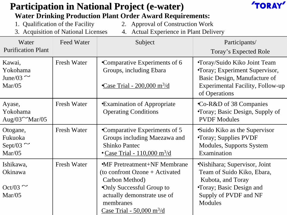
Participation in National Project (eParticipation in National Project (e--water)water)Water Drinking Production Plant Order Award Requirements:1. Qualification of the Facility 2. Approval of Construction Work3. Acquisition of National Licenses 4. Actual Experience in Plant Delivery
・Nishihara; Supervisor, JointTeam of Suido Kiko, Ebara, Kubota, and Toray
・Toray; Basic Design and Supply of PVDF and NF Modules
・MF Pretreatment+NF Membrane(to confront Ozone + Activated Carbon Method)
・Only Successful Group to actually demonstrate use of membranesCase Trial - 50,000 m3/d
Fresh WaterIshikawa,Okinawa
Oct/03 ~Mar/05
・Suido Kiko as the Supervisor ・Toray; Supplies PVDF
Modules, Supports System Examination
・Comparative Experiments of 5 Groups including Maezawa and Shinko Pantec
・ Case Trial - 110,000 m3/d
Fresh WaterOtogane,FukuokaSept/03 ~Mar/05
・Co-R&D of 38 Companies・Toray; Basic Design, Supply of
PVDF Modules
・Examination of Appropriate Operating Conditions
Fresh WaterAyase,YokohamaAug/03~Mar/05
・Toray/Suido Kiko Joint Team・Toray; Experiment Supervisor,Basic Design, Manufacture ofExperimental Facility, Follow-up of Operations
Participants/Toray’s Expected Role
・Comparative Experiments of 6 Groups, including Ebara
・Case Trial - 200,000 m3/d
Subject
Fresh Water
Feed Water
Kawai,YokohamaJune/03 ~Mar/05
Water Purification Plant

Conclusion Conclusion -- UF/MF Membranes for Drinking WaterUF/MF Membranes for Drinking Water
1. The Drinking Water Production Market is expanding rapidly,centering on the U.S. and Europe.
2. Toray has developed highly water-permeable and highly stable PVDF hollow fiber large modules suitable for drinking water production.
3. Although still in the experimental stage, Toray’s technologyis highly appraised, and we are aiming to enter the marketas soon as possible.

Immersed Membrane Modules Immersed Membrane Modules for Wastewater Treatmentfor Wastewater Treatment

Merit of Membrane BioMerit of Membrane Bio--reactorreactor
1. Good permeate quality1) Low COD concentration2) Low total nitrogen and total phosphorous3) No suspended solid4) Removal of bacteria and viruses
2. Very space efficient design
3. Considerable reduction of excess sludge
4. Reclamation of wastewaterIntegrated system with RO membrane

Flat Sheet Membrane or Hollow Fiber MembraneFlat Sheet Membrane or Hollow Fiber Membrane
Inter-fiber fouling causes flux decline
& fiber damage
Large membrane area per volume
Backwash cleaning
Hollow Fiber
Small membrane area per volume
Difficulty for backwash
Effective aeration perfootprint
Ease to remove fouling substances
Less pressure lossSmall dead space
Flat Sheet
DemeritMeritType

Flat Sheet Membrane or Hollow Fiber MembraneFlat Sheet Membrane or Hollow Fiber Membrane
Operation Time (h)
Tra
ns M
embr
ane
Pres
sure
(kPa
)
Flat Sheet Membrane
Hollow fiber membrane
0
10
20
30
40
50
100 200 300
Industrial Wastewater Treatment Test

Flat Sheet Membrane BioreactorFlat Sheet Membrane Bioreactor
Immersed Membrane
Membrane BioreactorRO
WastewaterEffluent
Reuse
Aeration
Element
Support
Effluent
Bubble
Activated Sludge
Membrane
FeedWater
Feed Water(Activated Sludge)
Effluent

Requirement and Design for Immersed Membrane Requirement and Design for Immersed Membrane
1. Chemical and physical durability2. High water permeability and high permeate quality3. Prevention for clogging
Requirement
1. Membrane material : Poly(vinylidene fluoride) (PVDF)
High stability for chemicals and high physical strength
2. Membrane form : Fiber reinforced membrane3. Surface pore : 1) Small pore size
2) Narrow pore size distribution3) Large pore number
HH
F Fn
Design Concept

Pore size of Flat Sheet MembranesPore size of Flat Sheet Membranes
Pore Size Distribution of Flat Sheet Membranes
東レBF014
クボタ
PVDF Membrane
Type B
東レBF014
クボタ
PVDF Membrane
Type B
3.0 micrometer
Num
ber
of p
ore
(1012
/ m2 )
0
0.5
1.0
1.5
0 0.2 0.4 0.6 0.8Pore size (micrometer)
3.0 micrometer

PVDF Flat Sheet Membrane Performance PVDF Flat Sheet Membrane Performance
Rejection of PSt latex particles
1.00 0.2 0.4 0.6 0.8
60
20
80
40
100
Rej
ectio
n (%
)
Particle size (micrometer)
Type BPVDF
0.40.08Average Surface Pore Size (micron)
1.44
PVDF Type B
0.90 Pure Water Flux (m3/m2/h, 10 kPa)
PVDF membrane has small pore and high flux

Chemical Resistance of PVDF Flat Sheet MembraneChemical Resistance of PVDF Flat Sheet Membrane
Soaking period (h)
Rej
ectio
n af
ter s
oak
Initi
al re
ject
ion
0
0.2
0.4
0.6
0.8
1
1.2
0 100 200 300
NaClO
Soaking period (h)
Flux
afte
r soa
kIn
itial
flux
0
0.2
0.4
0.6
0.8
1
1.2
0 100 200 300
NaClO
Purpose: Confirmation of membrane stability for cleaning chemical
Retention of Flux after soaking Retention of PSt rejection after soaking
Evaluation condition ResultPVDF MF membrane
1. is very stable in concentrated chlorine solution
2. can be cleaned with concentrated chlorine solution
1. Membrane configuration 2. Under cleaning condition(1,000ppm as Chlorine , pH=10)

Immersed Membrane ModuleImmersed Membrane ModuleSmall Test Module Large Size Module
Membrane Module
(10 elements)
Membrane Element (0.45m2)
Membrane
490mm
500m
m
Effluent
Membrane Module (24m2, 20 elements)
Diffuser
1,50
0mm
Housing
500mmMembrane Element
(1.2m2)

Module Type and Standard Operation ConditionModule Type and Standard Operation Condition
PVCPVCSUS
2.200.980.8050M1
2.203.000.80200M3
2.201.650.80100M2
DiffuserPermeate manifoldHousing
Material
Height (m)Depth (m)Width (m)Number of element
Dimension
Module typeModule Type
2 – 12pH5 – 40Temperature (degree C)
< 50Filtration pressure (kPa)10 - 15Air flow (NL/min/Element)
0.4 – 1.0Operation flux (m3/m2/d)
3,000 – 20,000MLSS (mg/L)Standard operation condition

Sludge Filtration Test Sludge Filtration Test (Small Test Module)(Small Test Module)
Operation Time [h]
Tra
ns M
embr
ane
Pres
sure
[kPa
]
0
2
4
6
8
10
1000 2000 3000
LV=0.4m/d LV=0.7m/d
Type B
PVDF
Turbidity(NTU)BOD (mg/L)COD (mg/L)
PVDF Type B Conventional1.250.20
3.55.1
0.213.45.0
3.86.1
Quality of EffluentTest Equipment
MLSS : 3,000-4,000 (mg/L)Tank Size : 750LMembrane Area : 1.6 m2

Comparison of Module PerformanceComparison of Module PerformanceModule Performance
(m3/footprint)Membrane Performance
(m3/m2)Membrane Area
(m2) 2= × =
(1.4) (1.5)(Compared to other modules)
0.0
0.5
1.0
1.5
2.0
0 1000 2000 3000 4000 5000 6000 7000 8000Operation (h)
Differential pressure = 2 kPa
Toray: 0.8 (m3/d)
Type B: 0.4 (m3/d)
Rinse
Mod
ule
Perf
orm
ance
(m3 /d
)
Toray module performance is twice as competent as othersToray module performance is twice as competent as others

Chemical Cleaning of PVDF Flat Sheet MembraneChemical Cleaning of PVDF Flat Sheet Membrane
NaClO NaClO NaClO(COOH)2Beforecleaning
Flux
rec
over
y (%
)
100
75
50
25
0Beforecleaning
1 - 31 – 2 (%)Oxalic acid2 – 51,000 (mg/L)Hydrogen peroxide2 – 51,000 – 5,000 (mg/L)Sodium hypochlorite
Cleaning time (h)ConcentrationChemical

Appearance of MBR
Module installation
Test conditionsPilot Test for Industrial Wastewater Pilot Test for Industrial Wastewater (Chemical plant)(Chemical plant)
25 - 32Degree CTemperature1.0 ~ 1.2Nm3/minScouring air flow
0.30 ~ 0.50m3/ m2 /dPermeate water flux137m2Membrane area
12,000 ~ 20,000mg/lMLSS5.5m3MBR vessel capacity
180 ~ 430mg/lBOD of raw water41 ~ 68m3/dInfluent flowValueUnitParameter
Influent and effluent quality
0.060.3mg/lTotal phosphorus2.318.6mg/lTotal nitrogen
None15mg/lSS8.4140mg/lCOD4.6230mg/lBOD7.47.6-pH
EffluentInfluentUnitParameter

Pilot Test for Brewery Wastewater Pilot Test for Brewery Wastewater (Small test module)(Small test module)
Operation Condition
12 - 15degree CTemperature0.24m3/m2/dPermeate water flux6.0m2Membrane area
4,000 – 5,500mg/LMLSS0.08 – 0.10kg-COD-Cr/kg-SS/dCOD-Cr per sludge weight
3,000mg/LCOD-Cr of raw waterBreweryUnitParameter
Result1. COD removal was more than 95 %
2. Suspended solid was removed completely
3. TMP was stabilized

Pilot Test for Municipal WastewaterPilot Test for Municipal WastewaterOperation Condition
13 - 16degree CTemperature0.53m3/m2/dPermeate water flux24m2Membrane area
7,800 - 5,000mg/LMLSS0.15 – 0.22kg-COD-Cr/kg-SS/dCOD-Cr per sludge weight
275mg/LCOD-Cr of raw waterMunicipalUnitParameter
Result1. COD removal was about 90 %
2. Suspended solid was removed completely
3. TMP was stabilized

Test for Municipal WastewaterTest for Municipal WastewaterPilot test started at Beverwijk WWTP in March 2003, cooperated with Seghers Keppel Technology Group (SKG)
TorayMembrane element supply
SKGMBR system design & build Operation

Test for Municipal Wastewater (Test for Municipal Wastewater (BeverwijkBeverwijk WWTP)WWTP)
System Configuration
AN1 AN2 DN1 DN2 DN3 N1 N2
MTINFLUENT
2 m3 2 m3 1,2 m3 1,2 m3 2,5 m3 4 m3 2,2 m3
PERMEAAT
F
FF
F
F
DODSNO3-N NH4-N PO4-P DO
AN1 AN2 DN1 DN2 DN3 N1 N2
MTINFLUENT
2 m3 2 m3 1,2 m3 1,2 m3 2,5 m3 4 m3 2,2 m3
PERMEAAT
F
FF
F
F
DODSNO3-N NH4-N PO4-P DO
PermeateInfluent
AN1 AN2 DN1 DN2 DN3 N1 N2
MTINFLUENT
2 m3 2 m3 1,2 m3 1,2 m3 2,5 m3 4 m3 2,2 m3
PERMEAAT
F
FF
F
F
DODSNO3-N NH4-N PO4-P DO
AN1 AN2 DN1 DN2 DN3 N1 N2
MTINFLUENT
2 m3 2 m3 1,2 m3 1,2 m3 2,5 m3 4 m3 2,2 m3
PERMEAAT
F
FF
F
F
DODSNO3-N NH4-N PO4-P DO
PermeateInfluent
AN1 AN2 DN1 DN2 DN3 N1 N2
MTINFLUENT
2 m3 2 m3 1,2 m3 1,2 m3 2,5 m3 4 m3 2,2 m3
PERMEAAT
F
FF
F
F
DODSNO3-N NH4-N PO4-P DO
AN1 AN2 DN1 DN2 DN3 N1 N2
MTINFLUENT
2 m3 2 m3 1,2 m3 1,2 m3 2,5 m3 4 m3 2,2 m3
PERMEAAT
F
FF
F
F
DODSNO3-N NH4-N PO4-P DO
AN1 AN2 DN1 DN2 DN3 N1 N2
MTINFLUENT
2 m3 2 m3 1,2 m3 1,2 m3 2,5 m3 4 m3 2,2 m3
PERMEAAT
F
FF
F
F
DODSNO3-N NH4-N PO4-P DO
AN1 AN2 DN1 DN2 DN3 N1 N2
MTINFLUENT
2 m3 2 m3 1,2 m3 1,2 m3 2,5 m3 4 m3 2,2 m3
PERMEAAT
F
FF
F
F
DODSNO3-N NH4-N PO4-P DO
PermeateInfluent
AN= Anaerobic zone, DN= Anoxic zone, N= Nitrification zone, MT= Membrane tank
137Membrane area (m2)120Design capacity (m3/d)

1. After 6 months of operation, no fouling measured on membranes2. No chemical cleaning necessary3. Without dosing chemicals the following effluent limits is reached
- PO4-P : 0.35 (mg/l)- NH4-N : 0.10 (mg/l)- NO3-N : 3.5 (mg/l)
4. Permeability is still more than 1,200 (l/m2/h/bar)5. The following flux data were obtained compared with others
Test for Municipal Wastewater (Test for Municipal Wastewater (Beverwijk Beverwijk WWTP)WWTP)
(l/m2/h)
121020Average flux (Dry Weather)353070Peak flux (Rain)454085Critical fluxBAToray
(based on “Membrantechnik in der Wasseraufbereitung und Abwasser be handlung, Aachen, 2003”)

ConclusionConclusion1. Flat sheet type immersed membrane with high flux,
small pore size and narrow pore size distribution has been developed.
2. Immersed membrane module was operated at low trans membrane pressure even in high activated sludge concentration.
3. Permeability was recovered after chemical cleaningand there was no damage of membrane.
4. Pilot tests were carried out at several WWTP plantsand operations were stable.

Conclusion Conclusion -- TorayToray’’s Membrane Separation Technology s Membrane Separation Technology
fofor Water Treatmentr Water Treatment
1. Toray is a synthetic membrane manufacturer whose productscover all types - RO, NF, UF, and MF.
2. Placing top priority on seawater desalination, drinking waterproduction, and wastewater treatment, Toray intends to expandits membrane technology business throughout the world.
3. High water quality and an Integrated Membrane System (IMS), a combination of several membranes, is required in the future market. Toray, possessing all types of membranes, is in an advantageous position in expanding business utilizing the IMS.

Toray can contribute to ensuring Toray can contribute to ensuring sustainable sustainable water resourceswater resources with membrane technologywith membrane technology
WastewaterRiver, Lake, Ground Water Sea Water