FNPT STANDARD OPERATING...
60
FNPT STANDARD OPERATING PROCEDURES In accordance with EASA-FCL and Global Aviation Training Manual Published by Global Aviation S.A. June 2018
Transcript of FNPT STANDARD OPERATING...

FNPT STANDARD OPERATING PROCEDURES
In accordance with EASA-FCL and Global Aviation Training Manual
Published by Global Aviation S.A.
June 2018

FNPT II STANDARD OPERATING PROCEDURES
GLOBAL AVIATION SA STANDARD OPERATING PROCEDURES Page 2 of 60
INTENTIONALLY LEFT BLANK

FNPT II STANDARD OPERATING PROCEDURES
GLOBAL AVIATION SA STANDARD OPERATING PROCEDURES Page 3 of 60
PREFACE
This manual has been developed by Global Aviation S.A., an EASA
Authorized Training Organization, and serves as an aid to all students
entering Phase IV of their flight training, but is not meant to serve as an
IR or theoretical handbook, therefore it is strongly suggested that the
students use this manual in conjunction with the appropriate training
manuals and handbooks where applicable.
The main use of this manual is to provide the student with information
on the FNPT device, its controls and characteristics and also to provide
the Standard Operating Procedures under which the sessions are to be
conducted. It is expected that the student will have studied this manual
and all other applicable manuals before commencing the FNPT sessions
and during the training, in order to optimize the training process and
achieve the maximum results.
This manual has been published for training only and under no
circumstances shall be used for real life navigation.
Special thanks to the team of people behind the making of this manual.
Christos Malamas
Head of Training
Global Aviation S.A.
FNPT II STANDARD OPERATING PROCEDURES
GLOBAL AVIATION SA STANDARD OPERATING PROCEDURES Page 4 of 60
INTENTIONALLY LEFT BLANK
FNPT II STANDARD OPERATING PROCEDURES
GLOBAL AVIATION SA STANDARD OPERATING PROCEDURES Page 5 of 60
TABLE OF CONTENTS
1. INTRODUCTION..............................................................7
2. SYSTEM DESCRIPTION...................................................12
3. LIMITATIONS................................................................23
4. NORMAL PROCEDURES.................................................26
5. ABNORMAL & EMERGENCY PROCEDURES....................40
6. APPENDIX.....................................................................53

FNPT II STANDARD OPERATING PROCEDURES
GLOBAL AVIATION SA STANDARD OPERATING PROCEDURES Page 6 of 60
INTENTIONALLY LEFT BLANK

FNPT II STANDARD OPERATING PROCEDURES
GLOBAL AVIATION SA STANDARD OPERATING PROCEDURES Page 7 of 60
1. INTRODUCTION

FNPT II STANDARD OPERATING PROCEDURES
GLOBAL AVIATION SA STANDARD OPERATING PROCEDURES Page 8 of 60
1. INTRODUCTION TABLE OF CONTENTS
1. Golden rules....................................................................................9
2. Task Sharing...................................................................................9
3. Normal Checklist.............................................................................9
4. Abnormal & Emergency Checklist...................................................9
5. Standard callouts & Phraseology.................................................10
6. How to use "Normal Porcedures".................................................10
FNPT II STANDARD OPERATING PROCEDURES
GLOBAL AVIATION SA STANDARD OPERATING PROCEDURES Page 9 of 60
1. GOLDEN RULES
AVIATE-NAVIGATE-COMMUNICATE
Aviate: fly the aircraft, with the appropriate attitude and power setting, for the current phase of flight. Ensure appropriate configuration timely.
Navigate: follow the assigned tracks/headings, altitudes and airspeeds (if so required). Maintain situational awareness, know your position in respect to terrain etc.
Communicate: advise ATC for your course of action, provide requested reports etc.
2. TASK SHARING
Since this is a single pilot aircraft, all actions are performed by the Pilot in Command.
Nevertheless, in the interest of the safety of the flight, the Pilot in Command may
delegate tasks to other crewmembers or even passengers, provided it is certain they
are able to cope with the task (e.g. reading of a checklist).
3. NORMAL CHECKLIST
While on ground, the checklist is performed on the read-and-do principle. This
means that the PIC will first read the action on the left column of the checklist, then
operate and confirm the relevant control or switch as dictated on the right column.
In flight, all actions mentioned in the checklist are performed by memory when
appropriate, in respect to the phase of flight. The checklist can then be used to
confirm that all actions have been performed.
4. ABNORMAL & EMERGENCY CHECKLIST
All failures shall be dealt with as soon as possible, using the appropriate memo
items, while managing the aircraft attitude and navigation. The abnormal checklist
shall be used to confirm that all actions have been performed, when safe to do so.
When minor failures or failures not directly affecting the safety of the flight occur,
the abnormal checklist may be used as a guidance for troubleshooting. The POH may
also be used for further guidance.
FNPT II STANDARD OPERATING PROCEDURES
GLOBAL AVIATION SA STANDARD OPERATING PROCEDURES Page 10 of 60
5. STANDARD CALLOUTS & PHRASEOLOGY
During critical phases of operation, like takeoff, approach etc, standard call-outs help
maintain situational awareness and provide guidance to the pilot for monitoring the
aircraft configuration and performance. In this manual, everything quoted e.g.
"AIRSPEED ALIVE" is a standard callout and should be used whenever indicated.
Whenever used, the word "shall" means that the relevant action is mandatory and
the crew is expected to perform as dictated. The word "should" is of a lesser
intensity, and means that the relevant action is good to be done, but not mandatory.
If used, the word "must" is equivalent to "shall".
6. HOW TO USE "NORMAL PROCEDURES"
Normal (and Abnormal) procedures are written in a manner that resembles most
airlines' Operational Manuals layout and phraseology. These are the exact
procedures to be used during each stage of flight. They are not a checklist, where the
student reads and does, but are procedures to be memorized and performed by
heart every time the flight phase requires so.

FNPT II STANDARD OPERATING PROCEDURES
GLOBAL AVIATION SA STANDARD OPERATING PROCEDURES Page 11 of 60
INTENTIONALLY LEFT BLANK

FNPT II STANDARD OPERATING PROCEDURES
GLOBAL AVIATION SA STANDARD OPERATING PROCEDURES Page 12 of 60
2. SYSTEM DESCRIPTION

FNPT II STANDARD OPERATING PROCEDURES
GLOBAL AVIATION SA STANDARD OPERATING PROCEDURES Page 13 of 60
A. GENERAL DESCRIPTION
The training device is built by Elite Simulations in Switzerland. It simulates a
generic low wing, twin engine, piston aeroplane, similar to Piper Seneca III.
The engines are turbocharged, counter-rotating and fitted with constant pitch
propellers. The undercarriage consists of two main wheels and a nose wheel,
is fully retractable and is hydraulically operated . The flaps are electrically
operated. The wings, stabilator and vertical stabilizer are fitted with leading
edge de-icing pneumatic boots and the propellers are fitted with electrical
anti-icing strips.
The training device is fitted with all necessary controls and switches to
replicate the exact operation of the aeroplane and the control wheels and
rudder pedals are coupled to a control load system, which simulates the
aerodynamic forces normally exerted on the controls.
The visual part of the device consists of a single projector and screen. The
graphics are generic, low detail terrain representations and generic, high
detail runway representations (including the respective markings and lighting
facilities). The database includes all Hellenic airspace, including navaids,
waypoints and airports.
The aim of the Training Device is not to train the student on the specific
aeroplane class/type, rather than to provide a realistic environment where all
basic and advanced IFR procedures may be practiced.
In the following pages, the general arrangement is presented along with
details on control panels, switches etc. The student pilots should take enough
time to familiarize themselves with the arrangement of the device and the
procedures described later on.
FNPT II STANDARD OPERATING PROCEDURES
GLOBAL AVIATION SA STANDARD OPERATING PROCEDURES Page 14 of 60
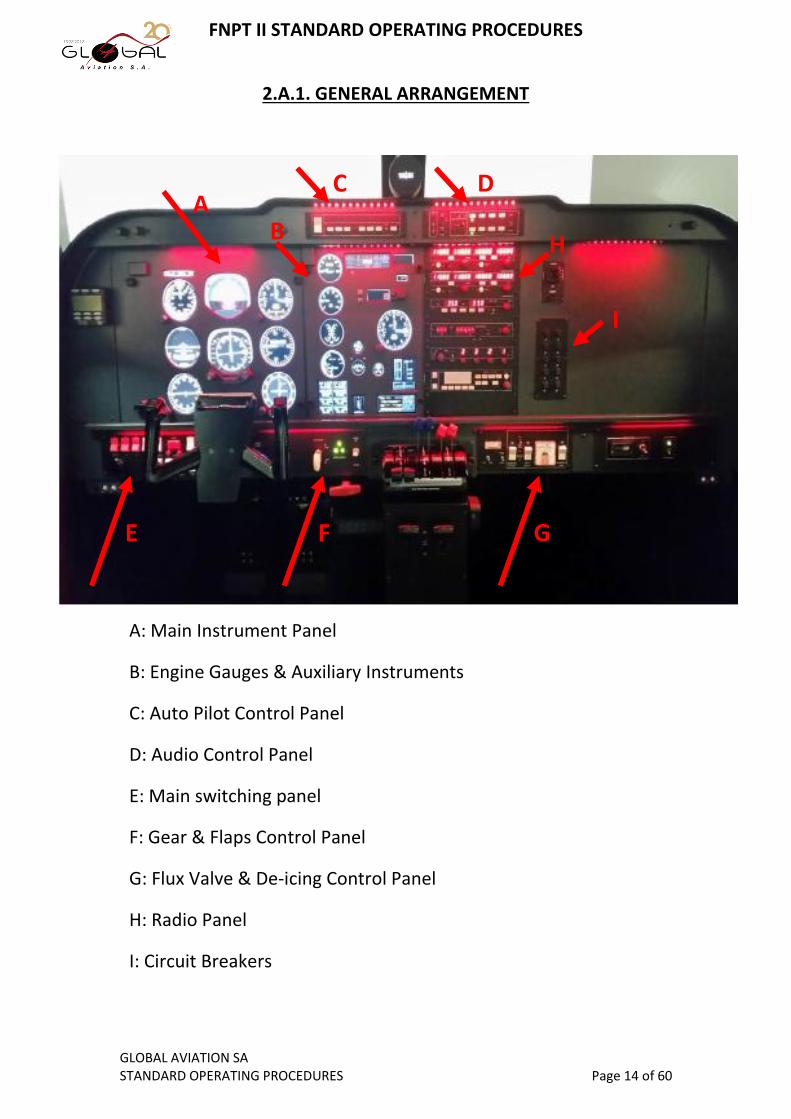
2.A.1. GENERAL ARRANGEMENT
A: Main Instrument Panel
B: Engine Gauges & Auxiliary Instruments
C: Auto Pilot Control Panel
D: Audio Control Panel
E: Main switching panel
F: Gear & Flaps Control Panel
G: Flux Valve & De-icing Control Panel
H: Radio Panel
I: Circuit Breakers
E F G
A B
C D
H
I

FNPT II STANDARD OPERATING PROCEDURES
GLOBAL AVIATION SA STANDARD OPERATING PROCEDURES Page 15 of 60
2.A.1A. Main Instrument Panel
A typical Main Instrument Panel, including:
Air Speed Indicator (ASI)
Attitude Indicator (AI)
Altitude Indicator (ALT)
Turn Coordinator (TC)
Horizontal Situational Indicator (HSI)
Vertical Speed Indicator (VSI)
Radio Magnetic Indicator (RMI)
Omni Bearing Indicator (OBI)
Parking Brake indicating light.
All the required instruments are fitted with the appropriate control
knobs.
For details on the operation of the instruments, refer to Global Aviation SA IR
handbook and to Bristol "Instruments" handbook.

FNPT II STANDARD OPERATING PROCEDURES
GLOBAL AVIATION SA STANDARD OPERATING PROCEDURES Page 16 of 60
2.A.1B. Engine Gauges & Auxiliary Instruments
This panel includes:
Engine Gauges Manifold Pressure
Propeller RPM
Exhaust Gas Temperature (EGT)
Fuel Flow
Fuel Tank level indicator
Oil Pressure Gauge
Oil Temperature Indicator
Cylinder Head Temperature Indicator (CHT)
Annunciator Panel
Altitude Alert system
Outside Air Temperature Indicator (OAT)
Ammeter
Vacuum Gauge
Flaps & Trims Indicator
Propeller Synchronizer
Cowl Flaps position Indicator
GPS panel
(for details on the operation of a Constant Speed drive,
refer to Bristol "AGK" handbook)

FNPT II STANDARD OPERATING PROCEDURES
GLOBAL AVIATION SA STANDARD OPERATING PROCEDURES Page 17 of 60
2.A.1C. Autopilot Control Panel
2.A.1D. Audio Control Panel
2.A.1E. Main Switching Panel

FNPT II STANDARD OPERATING PROCEDURES
GLOBAL AVIATION SA STANDARD OPERATING PROCEDURES Page 18 of 60
2.A.1F. Gear & Flaps Control Panel
2.A.1G. Flux Valve & De-icing Panel

FNPT II STANDARD OPERATING PROCEDURES
GLOBAL AVIATION SA STANDARD OPERATING PROCEDURES Page 19 of 60
2.A.1H. Radio Panel
This panel includes:
COM 1 & NAV 1, with tuning knobs, X'FER & IDENT buttons
COM 2 & NAV 2, with tuning knobs, X'FER & IDENT buttons
ADF, with integrated chronometer for Flight Time (FLT) &
Elapsed Time (ET).
DME, with remote tuning capability. Can be used with either
NAV 1 or NAV 2. Groundspeed & Time to Station indications
included.
TRANSPONDER with MODE C
GPS control panel.

FNPT II STANDARD OPERATING PROCEDURES
GLOBAL AVIATION SA STANDARD OPERATING PROCEDURES Page 20 of 60
On the pedestal, three additional control panels can be found:
Cowl Flaps & Alternate Air Controls
Fuel Selectors & Rudder Trim Controls

FNPT II STANDARD OPERATING PROCEDURES
GLOBAL AVIATION SA STANDARD OPERATING PROCEDURES Page 21 of 60
Pitch Trim Wheel & Indicator
The device also includes a conventional Yoke and a conventional
Power Quadrant associated with Twin Engine Constant Speed
Drive.
The Yoke, includes various switches to assist the pilots in controlling
some features of the aeroplane without removing their hands from
the control wheel. On the left hand grip, an electric trim switch, an
Auto Pilot Disconnection pushbutton and a Push to Talk switch. On
the right hand grip, a Flight Director On/Off switch.
The Power Quadrant includes all necessary levers for the control of
the propulsive equipment. 2 Throttles (black color), controlling the
Manifold Pressure of each engine, 2 Propeller Levers (blue color),
controlling the respective propeller RPM and 2 Mixture Levers (red
color), controlling the fuel ratio in each engine.

FNPT II STANDARD OPERATING PROCEDURES
GLOBAL AVIATION SA STANDARD OPERATING PROCEDURES Page 22 of 60
INTENTIONALLY LEFT BLANK

FNPT II STANDARD OPERATING PROCEDURES
GLOBAL AVIATION SA STANDARD OPERATING PROCEDURES Page 23 of 60
3. LIMITATIONS
FNPT II STANDARD OPERATING PROCEDURES
GLOBAL AVIATION SA STANDARD OPERATING PROCEDURES Page 24 of 60
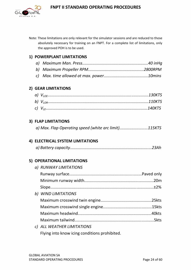
Note: These limitations are only relevant for the simulator sessions and are reduced to those
absolutely necessary for training on an FNPT. For a complete list of limitations, only
the approved POH is to be used.
1) POWERPLANT LIMITATIONS
a) Maximum Man. Press..........................................................40 inHg
b) Maximum Propeller RPM.................................................2800RPM
c) Max. time allowed at max. power.......................................10mins
2) GEAR LIMITATIONS
a) VLOE.........................................................................................130KTS
b) VLOR.........................................................................................110KTS
c) VLE..........................................................................................140KTS
3) FLAP LIMITATIONS
a) Max. Flap Operating speed (white arc limit).........................115KTS
4) ELECTRICAL SYSTEM LIMITATIONS
a) Battery capacity........................................................................23Ah
5) OPERATIONAL LIMITATIONS
a) RUNWAY LIMITATIONS
Runway surface................................................................Paved only
Minimum runway width.............................................................20m
Slope...........................................................................................±2%
b) WIND LIMITATIONS
Maximum crosswind twin engine.............................................25kts
Maximum crosswind single engine...........................................15kts
Maximum headwind.................................................................40kts
Maximum tailwind......................................................................5kts
c) ALL WEATHER LIMITATIONS
Flying into know icing conditions prohibited.

FNPT II STANDARD OPERATING PROCEDURES
GLOBAL AVIATION SA STANDARD OPERATING PROCEDURES Page 25 of 60
INTENTIONALLY LEFT BLANK

FNPT II STANDARD OPERATING PROCEDURES
GLOBAL AVIATION SA STANDARD OPERATING PROCEDURES Page 26 of 60
4. NORMAL PROCEDURES

FNPT II STANDARD OPERATING PROCEDURES
GLOBAL AVIATION SA STANDARD OPERATING PROCEDURES Page 27 of 60
4. NORMAL PROCEDURES TABLE OF CONTENTS
1. Cockpit preparation......................................................................28
2. Before Start..................................................................................28
3. Engine Start..................................................................................29
4. After Start.....................................................................................30
5. Before Taxi....................................................................................30
6. Before Takeoff..............................................................................31
7. Takeoff..........................................................................................31
8. After Takeoff.................................................................................32
9. Climb.............................................................................................32
10. Cruise............................................................................................32
11. Descend........................................................................................33
12. Approach......................................................................................34
13. Landing.........................................................................................37
14. After Landing................................................................................37
15. Go-around....................................................................................38
FNPT II STANDARD OPERATING PROCEDURES
GLOBAL AVIATION SA STANDARD OPERATING PROCEDURES Page 28 of 60
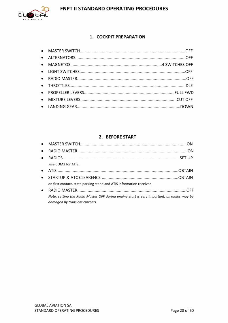
1. COCKPIT PREPARATION
MASTER SWITCH...........................................................................................OFF
ALTERNATORS...............................................................................................OFF
MAGNETOS...............................................................................4 SWITCHES OFF
LIGHT SWITCHES...........................................................................................OFF
RADIO MASTER..............................................................................................OFF
THROTTLES...................................................................................................IDLE
PROPELLER LEVERS..............................................................................FULL FWD
MIXTURE LEVERS...................................................................................CUT OFF
LANDING GEAR.........................................................................................DOWN
2. BEFORE START
MASTER SWITCH............................................................................................ON
RADIO MASTER...............................................................................................ON
RADIOS.....................................................................................................SET UP
use COM2 for ATIS.
ATIS.........................................................................................................OBTAIN
STARTUP & ATC CLEARENCE ..................................................................OBTAIN
on first contact, state parking stand and ATIS information received.
RADIO MASTER..............................................................................................OFF
Note: setting the Radio Master OFF during engine start is very important, as radios may be
damaged by transient currents.

FNPT II STANDARD OPERATING PROCEDURES
GLOBAL AVIATION SA STANDARD OPERATING PROCEDURES Page 29 of 60
3. ENGINE START
The procedure is identical for both engines. By default, starting sequence is Right then Left, but
may be altered according to the conditions.
ALTERNATOR..................................................................................................ON
AUX. FUEL PUMP.........................................................................................LOW
THROTTLE......................................................................HALF INCH (1cm) OPEN
PROPELLER..........................................................................................FULL FWD
MIXTURE.............................................................................................FULL RICH
PRIMER..........................................................................................AS REQUIRED
Note: avoid use of primer during hot days or when engine hot. On a standard/cold day, 3
seconds of priming are sufficient for a good engine start.
ANTI COLISSION BEACON...............................................................................ON
MAGNETOS..........................................................................................BOTH ON
AREA..........................................................................................................CLEAR
Shout "Clear Prop" and visually confirm that propeller area is clear.
STARTER.................................................................................................ENGAGE
Keep the starter switch depressed until RPM starts increasing.
OIL PRESSURE...........................................................................................GREEN
Note: Oil pressure must rise within 10" on a standard day. If not, shut down the engine
without delay. It is normal for the pressure to be higher than normal on a cold day.
REPEAT PROCEDURE FOR OTHER ENGINE.
Note: usually, simulator sessions begin with the engines running.

FNPT II STANDARD OPERATING PROCEDURES
GLOBAL AVIATION SA STANDARD OPERATING PROCEDURES Page 30 of 60
4. AFTER START
MASTER SWITCH............................................................................................ON
ALTERNATORS......................................................................................BOTH ON
AUX. FUEL PUMPS.............................................................................BOTH LOW
RADIO MASTER...............................................................................................ON
AMMETER..........................................................................................CHARGING
Verify battery charging and ammeter working either by switching on and off a heavy load (i.e.
pitot heat) or by setting both alternators to off.
ENGINE GAUGES.......................................................................................GREEN
LIGHTS............................................................................................AS REQUIRED
NAV lights ON, Anti collision ON
COMMS & NAVS.......................................................................................SET UP
Set up according to the ATC Clearance
TAKEOFF BRIEFING..............................................................................PERFORM
Perform the briefing in accordance with the SID
5. BEFORE TAXI
THROTTLES............................................................................................1000rpm
GYROS.......................................................................................................CHECK Check for red flags and appropriate indications (AI, HSI, RMI, TC)
ALTIMETERS.........................................................................SET & CROSSCHECK Set local QNH and crosscheck with airfield elevation. Limit: elevation ± 60ft
LIGHTS............................................................................................AS REQUIRED
AUTOPILOT....................................................................................................OFF Note: if Autopilot is engaged on the ground, the flights controls are stiff and taxi may be
compromised.
TRIMS...................................................................................................NEUTRAL
FLIGHT INSTRUMENTS..............................................................................CHECK Check for red flags and appropriate indications.
ENGINE GAUGES.......................................................................................CHECK
FUEL SELECTORS.......................................................................................X'FEED Select crossfeed to check the functionality of the system.

FNPT II STANDARD OPERATING PROCEDURES
GLOBAL AVIATION SA STANDARD OPERATING PROCEDURES Page 31 of 60
6. BEFORE TAKEOFF
MASTER SWITCH............................................................................................ON
ALTERNATORS......................................................................................BOTH ON
AUX. FUEL PUMPS.............................................................................BOTH LOW
MAGNETOS................................................................................4 SWITCHES ON
PROPELLERS........................................................................................FULL FWD
MIXTURES............................................................................................FULL RICH
COWL FLAPS...............................................................................................OPEN
TRIMS......................................................................................SET FOR TAKEOFF
FLAPS.......................................................................................SET FOR TAKEOFF Flaps 0
o for normal takeoff or 25
o for short/soft field
FUEL SELECTORS.............................................................................................ON
TAKEOFF BRIEFING...............................................................................CONFIRM
Amend the briefing with any changes in the ATC clearance
TRANSPONDER....................................................................................SET & ALT
Confirm that sqawk is set and set mode C entering the RWY
LANDING LIGHTS............................................................................................ON
7. TAKE OFF
TAKE OFF CLEARANCE.............................................................................OBTAIN
TAKE OFF POWER..........................................................................40''/2800rpm
"TAKE OFF POWER SET"...................................................................ANNOUNCE
DIRECTIONAL CONTROL.....................................................................MAINTAIN
ENGINE GAUGES.......................................................................................CHECK
"ENGINE GAUGES GREEN"...............................................................ANNOUNCE
AIRSPEED INCREASING..............................................................................CHECK
"AIRSPEED ALIVE".............................................................................ANNOUNCE
AT VR (80kts).............................................................ROTATE FOR 15o PITCH UP
WHEN POSITIVE RATE:
"POSITIVE RATE"...................................................................ANNOUNCE
Note: positive rate is checked when VSI is positive AND ALT is increasing
GEAR SELECTOR..............................................................................................UP
"GEAR UP"........................................................................................ANNOUNCE
Note: announce "GEAR UP" only after confirming that all gear indication lights are off
PASSING 500ft AGL MINIMUM:
PITCH..................................................................................10o PITCH UP
SET CLIMB POWER.............................................................35''/2500rpm
FNPT II STANDARD OPERATING PROCEDURES
GLOBAL AVIATION SA STANDARD OPERATING PROCEDURES Page 32 of 60
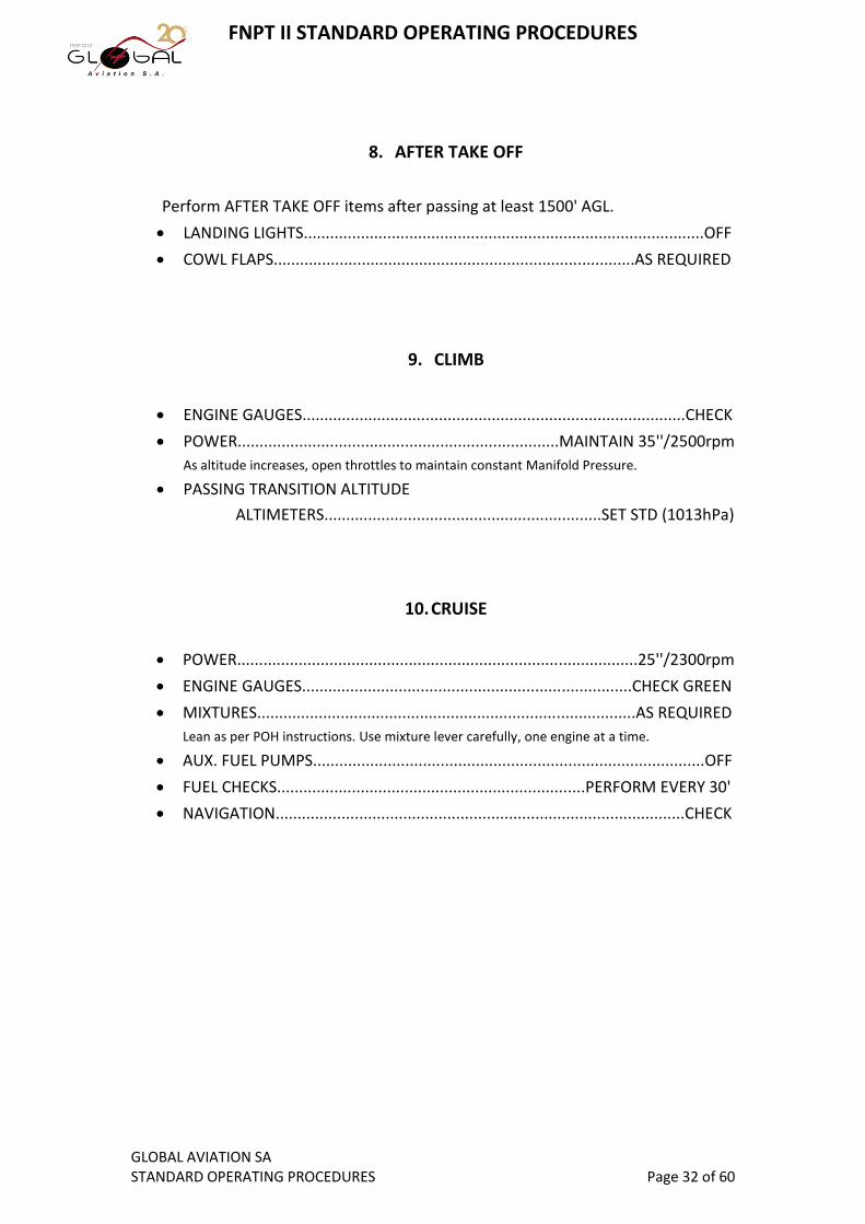
8. AFTER TAKE OFF
Perform AFTER TAKE OFF items after passing at least 1500' AGL.
LANDING LIGHTS...........................................................................................OFF
COWL FLAPS..................................................................................AS REQUIRED
9. CLIMB
ENGINE GAUGES.......................................................................................CHECK
POWER.........................................................................MAINTAIN 35''/2500rpm
As altitude increases, open throttles to maintain constant Manifold Pressure.
PASSING TRANSITION ALTITUDE
ALTIMETERS...............................................................SET STD (1013hPa)
10. CRUISE
POWER...........................................................................................25''/2300rpm
ENGINE GAUGES...........................................................................CHECK GREEN
MIXTURES......................................................................................AS REQUIRED
Lean as per POH instructions. Use mixture lever carefully, one engine at a time.
AUX. FUEL PUMPS.........................................................................................OFF
FUEL CHECKS......................................................................PERFORM EVERY 30'
NAVIGATION.............................................................................................CHECK
FNPT II STANDARD OPERATING PROCEDURES
GLOBAL AVIATION SA STANDARD OPERATING PROCEDURES Page 33 of 60
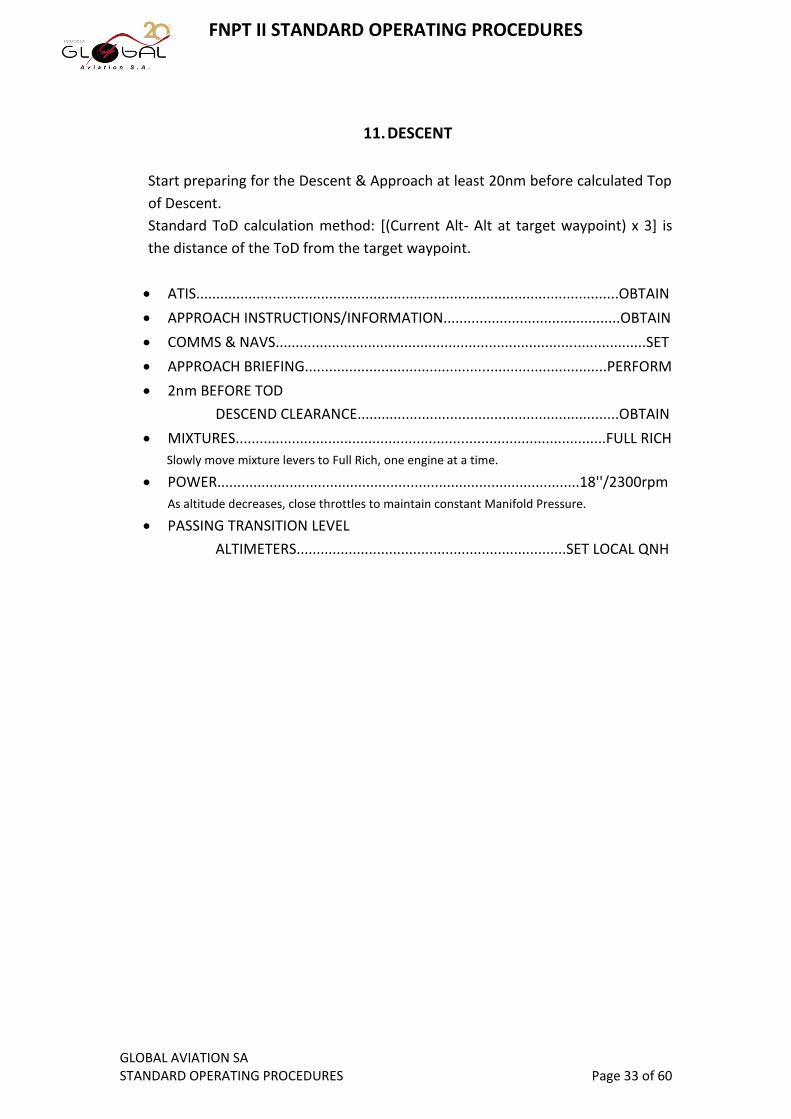
11. DESCENT
Start preparing for the Descent & Approach at least 20nm before calculated Top
of Descent.
Standard ToD calculation method: [(Current Alt- Alt at target waypoint) x 3] is
the distance of the ToD from the target waypoint.
ATIS.........................................................................................................OBTAIN
APPROACH INSTRUCTIONS/INFORMATION............................................OBTAIN
COMMS & NAVS............................................................................................SET
APPROACH BRIEFING...........................................................................PERFORM
2nm BEFORE TOD
DESCEND CLEARANCE.................................................................OBTAIN
MIXTURES............................................................................................FULL RICH
Slowly move mixture levers to Full Rich, one engine at a time.
POWER..........................................................................................18''/2300rpm
As altitude decreases, close throttles to maintain constant Manifold Pressure.
PASSING TRANSITION LEVEL
ALTIMETERS...................................................................SET LOCAL QNH

FNPT II STANDARD OPERATING PROCEDURES
GLOBAL AVIATION SA STANDARD OPERATING PROCEDURES Page 34 of 60
12. APPROACH
All approaches must be flown stabilized, ensuring proper configuration is
selected timely and correct flight path is followed throughout the approach.
As a general rule, final approach configuration must have been achieved by
1000' AAL latest.
Furthermore, all stabilization criteria must be satisfied by 1000' AAL in IMC or
500' in VMC in order to continue the approach. If any of the stabilization criteria
is not met by the minimum altitudes mentioned before, a go-around shall be
initiated without delay.
Stabilization criteria are:
The aircraft is on the correct path.
Only small changes in pitch/heading are required to maintain the
correct flight path.
The aircraft configuration is complete.
The correct approach speed is flown (Vapp min, Vapp+5 max).
Vertical speed is less than 1000fpm.
All briefings and checklists are completed.

FNPT II STANDARD OPERATING PROCEDURES
GLOBAL AVIATION SA STANDARD OPERATING PROCEDURES Page 35 of 60
12.i. PRECISION APPROACH (ILS)
LANDING LIGHTS............................................................................................ON
AUX. FUEL PUMPS..............................................................................BOTH LOW
APPROACH CLEARANCE..........................................................................OBTAIN
When 1 dot below the GS
POWER....................................................................................... 20''/2300rpm
ALTITUDE..........................................................................................MAINTAIN
SPEED........................................................................................BELOW 130KTS
"SPEED BELOW 130"......................................................................ANNOUNCE
GEAR.......................................................................................................DOWN
"3 GREEN-NO RED"........................................................................ANNOUNCE
SPEED..............................................................................................WHITE ARC
"SPEED CHECKED-WHITE ARC".......................................................ANNOUNCE
FLAPS.....................................................................................................SET 10o
Reaching Final Approach Point (established on LOC AND GS)
MANIFOLD PRESS........................................................................................18''
FINAL DESCENT.................................................................................ESTABLISH
PROPELLERS......................................................................................FULL FWD
APPROACH SPEED................................................................................... 95KTS
ALTITUDE ALERT.....................................................................................SET DA
BRAKES...................................................................................................CHECK
When Runway in sight and landing assured
FLAPS........................................................................................ SET 25o OR 40o
FNPT II STANDARD OPERATING PROCEDURES
GLOBAL AVIATION SA STANDARD OPERATING PROCEDURES Page 36 of 60
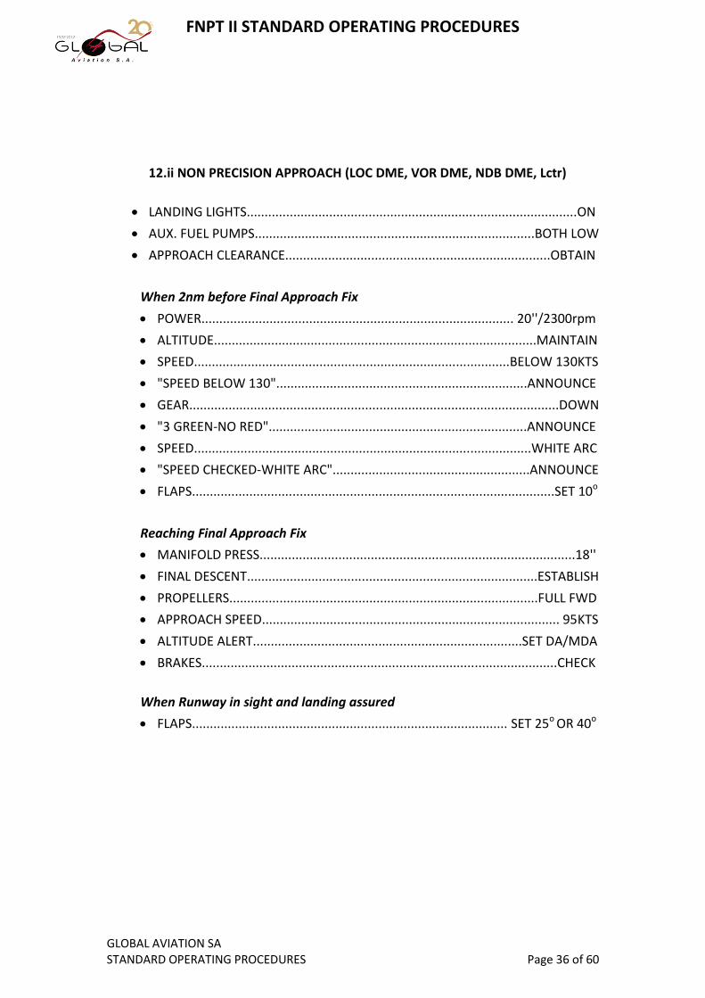
12.ii NON PRECISION APPROACH (LOC DME, VOR DME, NDB DME, Lctr)
LANDING LIGHTS............................................................................................ON
AUX. FUEL PUMPS..............................................................................BOTH LOW
APPROACH CLEARANCE..........................................................................OBTAIN
When 2nm before Final Approach Fix
POWER....................................................................................... 20''/2300rpm
ALTITUDE..........................................................................................MAINTAIN
SPEED........................................................................................BELOW 130KTS
"SPEED BELOW 130"......................................................................ANNOUNCE
GEAR.......................................................................................................DOWN
"3 GREEN-NO RED"........................................................................ANNOUNCE
SPEED..............................................................................................WHITE ARC
"SPEED CHECKED-WHITE ARC".......................................................ANNOUNCE
FLAPS.....................................................................................................SET 10o
Reaching Final Approach Fix
MANIFOLD PRESS........................................................................................18''
FINAL DESCENT.................................................................................ESTABLISH
PROPELLERS......................................................................................FULL FWD
APPROACH SPEED................................................................................... 95KTS
ALTITUDE ALERT...........................................................................SET DA/MDA
BRAKES...................................................................................................CHECK
When Runway in sight and landing assured
FLAPS........................................................................................ SET 25o OR 40o

FNPT II STANDARD OPERATING PROCEDURES
GLOBAL AVIATION SA STANDARD OPERATING PROCEDURES Page 37 of 60
13. LANDING
LANDING CHECKLIST......................................COMPLETE BY 1000ft AGL LATEST
LANDING CLEARANCE.............................................................................OBTAIN
The landing clearance may be issued as late as after passing the MDA/DA. Initiate a Go-
Around if no Landing Clearance has been obtained by 100ft AGL latest.
VISUAL CUES...........................................................................................OBTAIN
Note: depending on the approach type, different cues are required by the DA/MAPt, in order
to continue the approach or go-around. In any case, continue flying with the instruments until
both runway centerline and PAPI lights are visible.
REACHING DA/MAPt................................................CONTINUE or GO-AROUND
POWER.......................................................................IDLE WHEN APPROPRIATE
FLARE.....................................................................................................INITIATE
AFTER TOUCHDOWN
CENTERLINE...............................................................................MAINTAIN
BRAKES....................................................................USE AS APPROPRIATE
14. AFTER LANDING
WHEN RUNWAY VACATED
FLAPS..........................................................................................RETRACT
AUX. FUEL PUMPS..............................................................................OFF
TRANSPONDER..................................................................................STBY
LANDING LIGHTS.................................................................................OFF
RADIOS.....................................................................NON ESSENTIAL OFF
AFTER LANDING CHECKLIST..........PERFORM WHEN AIRCRAFT STOPPED

FNPT II STANDARD OPERATING PROCEDURES
GLOBAL AVIATION SA STANDARD OPERATING PROCEDURES Page 38 of 60
15. GO-AROUND
Considerations about the go-around:
The go-around IS a normal maneuver, and the crew shall initiate a go-around
whenever in any doubt. The maneuver is performed based on the AVIATE-
NAVIGATE-COMMUNICATE principle. Reasons for the execution of a go-around may
be (but are not limited to):
Loss of situational awareness.
If there is a malfunction that jeopardizes the safe completion of the approach.
Adequate visual cues are not obtained by reaching the DA/MAPt, or are lost.
ATC changes final approach instructions, causing rushed actions from the crew.
If during the approach, the aircraft becomes destabilized.
If tower wind limits are exceeding airplane or company limits.
The procedure begins when any crew member announces "Go-around". The primary
concern is to fly the aircraft away from the ground and achieve the appropriate
configuration as soon as possible, but avoiding rushed and uncoordinated actions.
The vertical part of the missed approach shall be followed immediately after the
initiation of the go-around, but the lateral part shall be executed only after passing
the Missed Approach Point (MAPt). As soon as the AVIATE and NAVIGATE parts are
satisfied (i.e the aircraft is climbing with the correct configuration and towards the
published missed approach procedure) then, COMMUNICATION with ATC shall not
be delayed.
POWER...............................................................................................................MAX Note: overboosting the engines is acceptable up to 500ft AGL. Depending on the height at which
the go-around is initiated, MAX power may not be required, in that case set climb power.
PITCH.............................................................ROTATE SMOOTHLY TO 15o PITCH UP Note: if the go-around is initiated at a height above 500ft AGL, then climb with 10
o PITCH UP
WHEN POSITIVE RATE OF CLIMB
"POSITIVE RATE".....................................................................ANNOUNCE Note: positive rate is checked when VSI is positive AND ALT is increasing
FLAPS.............................................................................................................SET 10o
GEAR.....................................................................................................................UP
"GEAR UP"..............................................................................................ANNOUNCE Note: announce "GEAR UP" only after confirming that all gear indication lights are off
WHEN GEAR IS UP
FLAPS...........................................................................................RETRACT
ATC................................................................................................................NOTIFY
PASSING 500ft AGL
PITCH.....................................................................................10o PITCH UP
POWER.................................................................................35''/2500rpm

FNPT II STANDARD OPERATING PROCEDURES
GLOBAL AVIATION SA STANDARD OPERATING PROCEDURES Page 39 of 60
INTENTIONALLY LEFT BLANK
FNPT II STANDARD OPERATING PROCEDURES
GLOBAL AVIATION SA STANDARD OPERATING PROCEDURES Page 40 of 60
5. ABNORMAL & EMERGENCY PROCEDURES

FNPT II STANDARD OPERATING PROCEDURES
GLOBAL AVIATION SA STANDARD OPERATING PROCEDURES Page 41 of 60
5. ABNORMAL & EMERGENCY PROCEDURES TABLE OF CONTENTS
1. Airspeeds for safe operation........................................................42
2. Rejected Takeoff..........................................................................43
3. Engine Failure...............................................................................44
i) General Considerations...........................................................44
ii) Identifying Dead Engine..........................................................44
iii) Securing the Engine (feathering).............................................45
iv) Engine Failure during Takeoff..................................................46
v) Engine Failure after Takeoff....................................................46
vi) Engine Failure in Flight............................................................47
4. One Engine Inoperative Approach................................................48
5. One Engine Inoperative Go-around..............................................49
6. Unsafe Gear Warnings.................................................................50
7. Electrical failures..........................................................................51
8. Tripped circuit breakers................................................................52

FNPT II STANDARD OPERATING PROCEDURES
GLOBAL AVIATION SA STANDARD OPERATING PROCEDURES Page 42 of 60
1. AIRSPEED FOR SAFE OPERATION
ONE ENGINE INOPERATIVE MINIMUM SPEED (VMCA)...............................66KIAS
Red radial line on the ASI
ONE ENGINE INOPERATIVE BEST RATE OF CLIMB (VYSE)...........................92KIAS
Blue radial line on the ASI. Commonly referred to as "Blue Line speed".
ONE ENGINE INOPERATIVE BEST ANGLE OF CLIMB (VXSE)........................80KIAS
MANEUVERING.......................................................................................140KIAS
NEVER EXCEED.......................................................................................205KIAS

FNPT II STANDARD OPERATING PROCEDURES
GLOBAL AVIATION SA STANDARD OPERATING PROCEDURES Page 43 of 60
2. REJECTED TAKEOFF
i. General Considerations
A take off shall be rejected whenever any failure that endangers the safety of the
flight occurs. Such failures include, but are not limited to, engine failures, all red
annunciator panel indications, any abnormal instrument indication (e.g no
airspeed), vibration, noise, smell, presence of smoke or whatever makes the Pilot
believe that the safety of the flight is endangered. When such a situation arises,
the following procedure shall be followed immediately:
Rejected Takeoff
"STOP"..............................................................................................ANNOUNCE
THROTTLES......................................................................................CLOSE BOTH
BRAKES.......................................................APPLY MAX (CONSIDER RWY STATE)
DIRECTION.....................................................................MAINTAIN CENTERLINE
WHEN AIRCRAFT STOPPED
o PARKING BRAKE.................................................................................SET
o ATC...............................................................................................NOTIFY
Use standard phraseology, including "PAN-PAN" or "MAYDAY" phrases as required.
Provide as much information as possible, regarding the state of the aircraft, the nature
of the failure and the kind of assistance required.
o IF EVACUATION REQUIRED...................SECURING THE AEROPLANE C/L
FNPT II STANDARD OPERATING PROCEDURES
GLOBAL AVIATION SA STANDARD OPERATING PROCEDURES Page 44 of 60
3. ENGINE FAILURE
i) General Considerations
An engine failure can be either an unexpected flame-out or a catastrophical
failure.
The flame-out may happen due to fuel starvation, unusual attitude of the aircraft
or other reasons, and usually does not produce any abnormal indications. In case
of a flame-out, a restart may be considered, depending on the phase of flight.
A catastrophical failure includes any mechanical failure of the propulsive unit
(engine or propeller) that deems the engine unsafe for further operation. Such
failures include, but are not limited to: oil starvation, high vibration, propeller or
governor damage or failure etc. Such failures usually produce the relevant
indications on the engine gauges and annunciator panel. Restarting the engine
shall not be attempted.
ii) Identifying dead engine
In case of engine failure, the aircraft will behave as follows:
Loss of thrust
Nose of the aircraft will yaw to the dead engine side
Yaw induced roll
Decay of airspeed
Nose down tendency
Since the immediate effect of an engine failure is a rather strong yaw tendency,
opposite rudder is required to maintain the heading. Thus, detection of a dead
engine happens instinctively, by application of the mnemonic "Dead foot-Dead
Engine", which means that the dead engine is on the side of the foot not pushing
any rudder pedal.
FNPT II STANDARD OPERATING PROCEDURES
GLOBAL AVIATION SA STANDARD OPERATING PROCEDURES Page 45 of 60
iii) Securing the engine procedure (feathering)
ALTITUDE AND DIRECTION.................................................................MAINTAIN
Use of stabilizer and rudder trim is strongly suggested, once the aircraft is under positive
control.
MIXTURES..................................................................................BOTH FULL RICH
PROPELLERS..............................................................................BOTH FULL FWD
THROTTLES...............................................................................BOTH FULL OPEN
WHEN AT SAFE ATTITUDE & AIRSPEED
o IDENTIFY DEAD ENGINE........................................DEAD FOOT-DEAD ENGINE
o VERIFY DEAD ENGINE............MOVE THROTTLE AND OBSERVE INDICATIONS
o IF NO DAMAGE...........................................CONSIDER RESTART PROCEDURE
MAGNETOS OF DEAD ENGINE......................................................RECYCLE
AUX.FUEL PUMP OF DEAD ENGINE....................................................HIGH
ENGINE GAUGES..................................................................CHECK GREEN
STARTER...........................................................ENGAGE IF NO ROTATION
IF UNSUCCESFUL...................................APPLY FEATHERING PROCEDURE
o IF DAMAGE.................................................APPLY FEATHERING PROCEDURE
PROPELLER LEVER OF DEAD ENGINE...........................................FEATHER
MIXTURE LEVER OF DEAR ENGINE................................................CUT OFF
AUX.FUEL PUMP OF DEAD ENGINE......................................................OFF
MAGNETOS OF DEAD ENGINE..............................................................OFF
ALTERNATOR OF DEAD ENGINE...........................................................OFF
ELECTRICAL LOAD....................................................CONSIDER REDUCING
POWER OF OPERATIVE ENGINE............................................AS REQUIRED

FNPT II STANDARD OPERATING PROCEDURES
GLOBAL AVIATION SA STANDARD OPERATING PROCEDURES Page 46 of 60
iv) Engine failure during Take-off
IF SUFFICIENT RUNWAY
o THROTTLES..................................................................................CLOSE BOTH
o DIRECTION.....................................................................................MAINTAIN
o BRAKES......................................................................................AS REQUIRED
o ATC...........................................................................NOTIFY WHEN STOPPED
IF INSUFFICIENT RUNWAY
o CONTINUE TAKEOFF.......................................................................CONSIDER
o IF TAKEOFF NOT SAFE
THROTTHLES...........................................................................CLOSE BOTH
BRAKES.....................................................................APPLY MAX BRAKING
FUEL SELECTORS...................................................................................OFF
BATTERY MASTER.................................................................................OFF
DIRECTION.....................................................TURN TO AVOID OBSTACLES
ATC......................................................................NOTIFY WHEN STOPPED
v) Engine failure after Take-off
IF SUFFICIENT RUNWAY
o LAND STRAIGHT AHEAD.................................................................CONSIDER
IF INSUFFICIENT RUNWAY OR DECISION IS TO CONTINUE
o DIRECTION.....................................................................................MAINTAIN
o CLIMB.............................................................................................ESTABLISH
o SPEED..................................................................MAINTAIN VYSE (BLUE LINE)
o LANDING GEAR.............................................RETRACT WHEN POSITIVE RATE
Note: positive rate is checked when VSI is positive AND ALT is increasing
o DEAD ENGINE PROPELLER.......................................................FEATHER ASAP
After feathering the propeller the drag is greatly reduced and the aircraft resumes a
better rate of climb, thus it is very important to feather the propeller as soon as possible,
without compromising the safety of the flight.
o ABOVE SAFE ALTITUDE.......................CONSIDER RESTART OR SECURE PROC
At least 1000ft AGL.
o ATC......................................................................................................NOTIFY
Communication with ATC shall not be delayed, but the pilot should ensure that the
aircraft is safely established on the climb and the desired track before attempting any
task other that flying the aircraft.
o FOR APPROACH....................................ONE ENGINE INOP APPROACH PROC

FNPT II STANDARD OPERATING PROCEDURES
GLOBAL AVIATION SA STANDARD OPERATING PROCEDURES Page 47 of 60
vi) Engine Failure in Flight
THROTTLES...............................................................................BOTH FULL OPEN
PROPELLERS..............................................................................BOTH FULL FWD
MIXTURES..................................................................................BOTH FULL RICH
DIRECTION AND ALTITUDE................................................................MAINTAIN If unable to maintain altitude, notify ATC and establish shallow descent. Use stabilizer and
rudder trims to ensure smooth control inputs and reduce workload
DEAD ENGINE........................................................................................IDENTIFY
VERIFY DEAD ENGINE.................MOVE THROTTLE AND OBSERVE INDICATIONS
DAMAGE OR NO DAMAGE..................................................................CONSIDER
o IF NO DAMAGE...........................................CONSIDER RESTART PROCEDURE
MAGNETOS OF DEAD ENGINE......................................................RECYCLE
AUX.FUEL PUMP OF DEAD ENGINE....................................................HIGH
ENGINE GAUGES..................................................................CHECK GREEN
STARTER............................................................ENGAGE IF NO ROTATION
IF UNSUCCESFUL....................................APPLY FEATHERING PROCEDURE
o IF DAMAGE.................................................APPLY FEATHERING PROCEDURE
PROPELLER LEVER OF DEAD ENGINE...........................................FEATHER
MIXTURE LEVER OF DEAR ENGINE................................................CUT OFF
AUX.FUEL PUMP OF DEAD ENGINE......................................................OFF
MAGNETOS OF DEAD ENGINE..............................................................OFF
ALTERNATOR OF DEAD ENGINE...........................................................OFF
ELECTRICAL LOAD....................................................CONSIDER REDUCING
POWER OF OPERATIVE ENGINE............................................AS REQUIRED
DIVERSION..........................................................................................CONSIDER
FOR APPROACH.........................................ONE ENGINE INOP APPROACH PROC

FNPT II STANDARD OPERATING PROCEDURES
GLOBAL AVIATION SA STANDARD OPERATING PROCEDURES Page 48 of 60
4. ONE ENGINE INOPERATIVE APPROACH
The approach will be carried out according to ATC instructions, following normal
procedures. The differences between a normal approach and a single engine
approach have been established to ensure an approach with less drag and
consequently less power requirements (delivered by the remaining engine). The pilot
must keep in mind that very smooth power adjustments shall be applied, as the yaw
moment produced by the single engine may result in excessive LOC or Course
deviations.
APPROACH PREPARATIONS...............................................................COMPLETE
BRIEFING................................................CONSIDER GO-AROUND LIMITATIONS
LANDING LIGHTS............................................................................................ON
Approaching FAP/FAF
FINAL DESCENT...................................................................................ESTABLISH
POWER...........................................................................................AS REQUIRED
PROPELLER..........................................................................................FULL FWD
SPEED..........................................................................................BELOW 130KTS
"SPEED BELOW 130".........................................................................ANNOUNCE
GEAR.........................................................................................................DOWN
"3 GREEN-NO RED"...........................................................................ANNOUNCE
SPEED.......................................................................MAINTAIN VYSE (BLUE LINE)
WHEN RUNWAY IN SIGHT AND LANDING ASSURED
o SPEED............................................................................................WHITE ARC
o "SPEED CHECKED-WHITE ARC"....................................................ANNOUNCE
o FLAPS..................................................................EXTEND GRADUALLY TO 40o
o RUDDER TRIM...................................SET TO NEUTRAL-USE RUDDER PEDALS
FOR TOUCHDOWN.................................................APPLY NORMAL TECHNIQUE

FNPT II STANDARD OPERATING PROCEDURES
GLOBAL AVIATION SA STANDARD OPERATING PROCEDURES Page 49 of 60
5. ONE ENGINE INOPERATIVE GO-AROUND
Such a procedure is strongly not recommended by the aircraft manufacturer, as
above standard pilot skills are required. Nevertheless, no pilot shall force a landing if
any reason for a go-around exists. In case a go-around is necessary, apply following
procedure without delay.
THROTTLE.....................................................................SMOOTHLY SET TO MAX
CLIMB.................................................................................................ESTABLISH
DIRECTION..........................................................................................MAINTAIN
Up to full rudder may be needed. Use ailerons with care.
SPEED.......................................................................MAINTAIN VYSE (BLUE LINE)
WHEN POSITIVE RATE OF CLIMB
o "POSITIVE RATE"........................................................................ANNOUNCE Note: positive rate is checked when VSI is positive AND ALT is increasing
o FLAPS................................................................................................SET 10o
o GEAR........................................................................................................UP
o "GEAR UP".................................................................................ANNOUNCE Note: announce "GEAR UP" only after confirming that all gear indication lights are off
o WHEN GEAR IS UP
FLAPS..............................................................................................RETRACT
MISSED APPROACH PROCEDURE...........................................................FOLLOW
ATC...........................................................................................................NOTIFY
WHEN AT SAFE ALTITUDE...................................................................LEVEL OFF
POWER...........................................................................................AS REQUIRED
FOR APPROACH
ATC INSTRUCTIONS...........................................................................FOLLOW
ONE ENGINE INOP PROCEDURE............................................................APPLY
FNPT II STANDARD OPERATING PROCEDURES
GLOBAL AVIATION SA STANDARD OPERATING PROCEDURES Page 50 of 60
6. UNSAFE GEAR INDICATIONS
If during Landing Gear operation, position of the gear does not agree with
commanded position, the indicating lights will notify the Pilot on the situation. The
normal indications are:
GEAR UP & LOCKED : No lights
GEAR DOWN & LOCKED: 3 Green lights
Red lights indicate Gear in Transit or unsafe gear. In such a case, a "GEAR" warning
light will light up and will remain lit on the Annunciator Panel.
IF DURING RETRACTION RED LIGHT ON ONE OR MORE WHEELS
o SPEED................................................................................LESS THAN 110KTS
o GEAR SELECTOR................................................................................RECYCLE
o INDICATIONS..........................................................................ALL LIGHTS OFF
o IF UNSUCCESFUL........................................FUEL CONSUMPTION INCREASED
IF DURING EXTENSION RED LIGHT ON ONE OR MORE WHEELS
o SPEED................................................................................LESS THAN 130KTS
o GEAR SELECTOR................................................................................RECYCLE
o INDICATIONS.....................................................................................3 GREEN
o IF UNSUCCESFUL.................................................MANUAL EXTENSION PROC
GEAR SELECTOR...............................................................................DOWN
MANUAL EXTENSION HANDLE...........................................................PULL
WHEN ANNUNCIATOR "GEAR" LIGHT OUT....................RELEASE HANDLE
INDICATIONS................................................................................3 GREEN

FNPT II STANDARD OPERATING PROCEDURES
GLOBAL AVIATION SA STANDARD OPERATING PROCEDURES Page 51 of 60
7. ELECTRICAL FAILURES
In the case where single pieces of equipment fail, the respective Circuit Breakers will
trip, rendering the system inoperative. If the safety of the flight is impacted, the
relevant procedure may be applied for resetting the c/b's.
In case of more severe failures, like Alternator failures or even complete Electrical
Failure, the following procedure shall be applied.
WHEN "ALTERNATOR" WARNING LIGHT ON ANNUNCIATOR PANEL
o AMMETER.............................................................................................CHECK
o ELECTRICAL LOAD..............................................................................REDUCE Switch off all non essential lights and radios.
o ALTERNATOR SWITCHES................................................RECYCLE ON BY ONE
o IF NONE RECOVERS
POWER...............................................................................BATTERY ONLY
ELECTRICAL LOAD..................................................REDUCE TO MINIMUM One radio, X'ponder, DME if required
DIVERSION.................................................................................CONSIDER
IF BATTERY DEPLETED.....................................LOST COMMS PROCEDURE
LANDING GEAR.................MANUAL EXTENSION ONLY - NO INDICATIONS
FLAPS................................................................................NOT AVAILABLE
FNPT II STANDARD OPERATING PROCEDURES
GLOBAL AVIATION SA STANDARD OPERATING PROCEDURES Page 52 of 60
8. TRIPPED CIRCUIT BREAKERS
It is strongly discouraged to reset any tripped c/b's in flight. Nevertheless, if the Pilot
believes that the safety of the flight is impacted by the inoperative systems,
following procedure may be applied.
TIME..........................................................................................................CHECK
WHEN AT LEAST TWO MINUTES HAVE ELAPSED
Allow two minutes time for cooling down the c/b
o CIRCUIT BREAKERS...........................................................RESET ONE BY ONE
IF SUCCESFUL.......................................CONTINUE NORMAL OPERATIONS
IF C/B TRIPS AGAIN OR DOES NOT LATCH..................AFFECTED SYS INOP
DIVERSION.................................................................................CONSIDER
IT IS PROHIBITED TO RESET ANY C/B MORE THAN ONCE

FNPT II STANDARD OPERATING PROCEDURES
GLOBAL AVIATION SA STANDARD OPERATING PROCEDURES Page 53 of 60
INTENTIONALLY LEFT BLANK

FNPT II STANDARD OPERATING PROCEDURES
GLOBAL AVIATION SA STANDARD OPERATING PROCEDURES Page 54 of 60
6. APPENDIX

FNPT II STANDARD OPERATING PROCEDURES
GLOBAL AVIATION SA STANDARD OPERATING PROCEDURES Page 55 of 60

FNPT II STANDARD OPERATING PROCEDURES
GLOBAL AVIATION SA STANDARD OPERATING PROCEDURES Page 56 of 60
INTENTIONALLY LEFT BLANK

FNPT II STANDARD OPERATING PROCEDURES
GLOBAL AVIATION SA STANDARD OPERATING PROCEDURES Page 57 of 60

FNPT II STANDARD OPERATING PROCEDURES
GLOBAL AVIATION SA STANDARD OPERATING PROCEDURES Page 58 of 60
INTENTIONALLY LEFT BLANK
FNPT II STANDARD OPERATING PROCEDURES
GLOBAL AVIATION SA STANDARD OPERATING PROCEDURES Page 59 of 60

FNPT II STANDARD OPERATING PROCEDURES
GLOBAL AVIATION SA STANDARD OPERATING PROCEDURES Page 60 of 60
INTENTIONALLY LEFT BLANK