
FMUX04E User Manual - Amazon S3. This manual is divided into 5 Chapters, the Introduction,...
64
FMUX04E Fiber Optical Multiplexer 4 Channel Fixed G.703 E1, DS1(T1) Plus Wire Speed 100M Ethernet SNMP Manageable (Option)
Transcript of FMUX04E User Manual - Amazon S3. This manual is divided into 5 Chapters, the Introduction,...

FMUX04E
Fiber Optical Multiplexer 4 Channel Fixed G.703 E1, DS1(T1) Plus Wire Speed 100M Ethernet SNMP Manageable (Option)


The information contained in this document is subject to change without prior notice. TRADEMARKS Microsoft is a registered trademark of Microsoft Corp. HyperTerminal™ is a registered trademark of Hilgraeve Inc. WARNING:
This equipment has been tested and found to comply with the limits for a Class A digital device, pursuant to Part 15 of the FCC Rules. These limits are designed to provide reasonable protection against harmful interference when the equipment is operated in a commercial environment. This equipment generates, uses, and can radiate radio frequency energy and if not installed and used in accordance with the instruction manual may cause harmful interference in which case the user will be required to correct the interference at his own expense. NOTICE: (1) The changes or modifications not expressively approved by the party responsible for compliance could void the user's authority to operate the equipment. (2) Shielded interface cables and AC power cord, if any, must be used in order to comply with the emission limits. CISPR PUB.22 Class A COMPLIANCE:
This device complies with EMC directive of the European Community and meets or exceeds the following technical standard. EN 55022 - Limits and Methods of Measurement of Radio Interference Characteristics of Information Technology Equipment. This device complies with CISPR Class A. WARNING:
This is a Class A product. In a domestic environment this product may cause radio interference in which case the user may be required to take adequate measures. CE NOTICE
Marking by the symbol CE indicates compliance of this equipment to the EMC and LVD directives of the European Community. Such marking is indicative that this equipment meets or exceeds the following technical standards: EN 55022:2006, Class A, IEC61000-3-2:2005 and IEC61000-3-3:2005, EN50024:1998+A1:2001+A2:2003, and EN60950-1:2001

CTC Union Technologies Co., Ltd. Far Eastern Vienna Technology Center (Neihu Technology Park) 8F, No. 60, Zhouzi St. Neihu, Taipei, 114 Taiwan Phone: +886-2-2659-1021 FAX: +886-2-2799-1355 FMUX04E User Manual Fiber Multiplexer with 4 channels E1 or T1 plus 100M Ethernet Version 1.0 Dec 2010 (First Release) This manual supports the following models: FMUX04E
This document is the first official release manual. Please check CTC Union's website for any updated manual or contact us by E-mail at [email protected]. Please address any comments for improving this manual or to point out omissions or errors to [email protected]. Thank you.
The information and specifications in this document are subject to change without notice.

Table of Contents
i
Table of Contents CHAPTER 1. INTRODUCTION .................................................................................................................................... 7 1.1 GENERAL DESCRIPTION...................................................................................................................................................7 1.2 FUNCTIONAL AND FEATURE DESCRIPTION...........................................................................................................................7 1.3 FEATURES LIST ..............................................................................................................................................................8 1.4 PACKING LIST................................................................................................................................................................9 1.5 TECHNICAL SPECIFICATIONS ...........................................................................................................................................10 1.5.1 E1 Link ..............................................................................................................................................................10 1.5.2 T1 Link ..............................................................................................................................................................10 1.5.3 Ethernet Trunk Link ..........................................................................................................................................10 1.5.4 RS‐232 Clear Channel .......................................................................................................................................10 1.5.5 RS‐232 Console/Alarm Port..............................................................................................................................10 1.5.6 Order Wire........................................................................................................................................................11 1.5.7 LED Indicators...................................................................................................................................................11 1.5.8 Optical Specifications .......................................................................................................................................11 1.5.9 Physical.............................................................................................................................................................12 1.5.10 Power supply ..................................................................................................................................................12 1.5.11 Environment (Operating) ...............................................................................................................................12 1.5.12 Miscellaneous.................................................................................................................................................12
1.6 E1 SIGNAL STRUCTURE .................................................................................................................................................12 1.6.1 E1 link line rate and coding ..............................................................................................................................12
1.7 T1(DS1) SIGNAL STRUCTURE ........................................................................................................................................13 1.7.1 T1 link line rate and coding ..............................................................................................................................13
1.8 APPLICATIONS / CAPABILITIES ........................................................................................................................................14 CHAPTER 2. INSTALLATION.................................................................................................................................... 15 2.1 GENERAL ...................................................................................................................................................................15 2.2 SITE PREPARATION.......................................................................................................................................................15 2.3 UNPACKING................................................................................................................................................................15 2.4 MECHANICAL ASSEMBLY................................................................................................................................................16 2.5 ELECTRICAL INSTALLATION..............................................................................................................................................17 2.5.1 Power connection, AC ......................................................................................................................................17 2.5.2 Power connection, DC ......................................................................................................................................17 2.5.3 Power connection, AC+DC................................................................................................................................17
2.6 REAR PANEL CONNECTORS.............................................................................................................................................17 2.7 FRONT PANEL SWITCHES, CONNECTORS AND INDICATORS ....................................................................................................18 2.8 SNMP REMOVAL/REPLACEMENT PROCEDURES .................................................................................................................18
CHAPTER 3. OPERATION ........................................................................................................................................ 19 3.1 INTRODUCTION ............................................................................................................................................................19 3.2 TERMINAL MODE OPERATION........................................................................................................................................19 3.3 CONNECTING TO THE FMUX04E ...................................................................................................................................19 3.4 CONFIGURING IN CONSOLE MODE ..................................................................................................................................20 3.4.0 Local Login........................................................................................................................................................20 3.4.1 Device...............................................................................................................................................................21 3.4.2 Fiber .................................................................................................................................................................21 3.4.3 E1/T1 ................................................................................................................................................................23 3.4.4 LAN...................................................................................................................................................................24 3.4.5 RS‐232 ..............................................................................................................................................................25 3.4.6 Phone (Order Wire) ..........................................................................................................................................26 3.4.7 Password ..........................................................................................................................................................26 3.4.8 Remote .............................................................................................................................................................27
3.5 CONFIGURING VIA THE LCD/MENU .................................................................................................................................27 3.5.1 Menu Structure ................................................................................................................................................27 3.5.2 Operation detail ...............................................................................................................................................28
3.6 SNMP.......................................................................................................................................................................30 3.7 UPGRADE FIRMWARE USING THE UPGRADE TOOL ...............................................................................................................31

Table of Contents
ii
CHAPTER 4. SNMP..................................................................................................................................................35 4.1 GENERAL................................................................................................................................................................... 35 4.2 SNMP OPERATIONS .................................................................................................................................................... 35 4.3 THE MANAGEMENT INFORMATION BASE ......................................................................................................................... 35 4.4 MIB STRUCTURE ......................................................................................................................................................... 36 4.5 SNMP COMMUNITIES ................................................................................................................................................. 36 4.6 CONFIGURING THE SNMP AGENT .................................................................................................................................. 37 4.6.3 TFTP and Upgrade Firmware........................................................................................................................... 38
4.7 MIB FILE ................................................................................................................................................................... 39 4.8 WEB BASED INTERFACE ................................................................................................................................................ 40 4.8.1 Security Login .................................................................................................................................................. 40 4.8.2 Panel................................................................................................................................................................ 40 4.8.3 Local (Remote) Tab Display ............................................................................................................................. 40 4.8.4 Device .............................................................................................................................................................. 41 4.8.5 Fiber................................................................................................................................................................. 42 4.8.6 SFP ................................................................................................................................................................... 42 4.8.7 E1/T1 Configuration ........................................................................................................................................ 43 4.8.8 LAN .................................................................................................................................................................. 43 4.8.9 RS232 & Phone ................................................................................................................................................ 44 4.8.10 SNMP Manager and Trap.............................................................................................................................. 44 4.8.11 System Configuration .................................................................................................................................... 45
APPENDIX A. MISCELLANEOUS...............................................................................................................................47 A.1 CONSOLE PORT PIN ASSIGNMENT.................................................................................................................................... 47 A.2 ALARM RELAY CONNECTION DETAIL................................................................................................................................ 47 A.3 RS‐232 CLEAR CHANNEL DETAIL ................................................................................................................................... 47 A.4 CONSOLE CABLE PIN ASSIGNMENT CAB‐DB9DB9F‐232‐3................................................................................................. 48 A.5 LAN PIN ASSIGNMENT.................................................................................................................................................. 48 A.6 E1/T1 RJ‐45 PIN ASSIGNMENT ..................................................................................................................................... 48 A.7 LAN/SNMP RJ‐45 PIN ASSIGNMENT............................................................................................................................. 49 A.8 SNMP TRAP MESSAGES AND ALARMS............................................................................................................................ 49 A.9 SNMP OBJECT DETAILS ............................................................................................................................................... 50

Chapter 1: Introduction
7
Chapter 1. Introduction
Thank you for choosing the FMUX04E. If you would like to skip right to the installation and configuration of the Multiplexer, proceed to Chapters 2 and 3.
This manual is used to explain the installation and operating procedures for the FMUX04E, 4 Port Fiber Optical E1/T1 + 100M Ethernet Multiplexer, and present its capabilities and specifications. This manual is divided into 5 Chapters, the Introduction, Installation, Operation, Loop Back Testing and SNMP chapters. The Appendix includes the pin assignments of special cables and gives further information on options for placing the device in service.
The divisions of the manual are intended for use by personnel to answer questions in general areas. Planners and potential purchasers may read the Introduction to determine the suitability of the product to its intended use; Installers should read the Installation Chapter and the Cabling Specification Appendix; Operating Personnel would use the Operations Chapter to become familiar with the settings. Operating Personnel and Network Administrators should read the chapters on loop back testing and on SNMP to become familiar with the diagnostic capabilities, network settings and management strategies when the optional SNMP card is installed.
1.1 General Description
The FMUX04E is a 1U (1.75") high standalone or half rack mountable E1/T1 multiplexer plus 100M Ethernet over fiber link designed for cost effective applications. The FMUX04E provides an economic optical connection solution in low-density E1 or T1 installations such as between remote offices or in mobile back-haul applications, where multiple high speed synchronous TDM (Time Division Multiplexing) communications and Ethernet packets are required over a single fiber pair (or single BiDi fiber core). By utilizing a fixed channel design, the unit is extremely cost effective and provides quick return on investment.
1.2 Functional and Feature Description
The standard unit is a standalone chassis with LCD / menu keys, local control via Console port and ordered with either AC, DC or dual AC+DC input power. The appropriate SFP optical transceiver(s) with LC connector(s) may be selected when ordering to support multi-mode or single-mode fiber cable operation, with a variety of power options. WDM (Wave Division Multiplexing) optical transceivers are also available to provide bi-directional transmission on a single fiber to reduce cost when using leased dark fiber links. The range of transmission for optical connection is from 2Km (for multi-mode) up to 120Km (single mode).
The FMUX04E fiber aggregate is a combination of up to four G.703 E1 or T1(DS1) streams, a wire speed 100M Ethernet trunk channel which terminates at a 3 LAN user ports Layer 2 switch, a clear channel RS-232 that supports asynchronous speeds up to 250k baud, bi-directional audio channels (Order Wire) and an Embedded Operations Channel (EOC) for remote management and monitoring.
SNMP (for local and remote management purposes) is an option that may be factory ordered or may be ordered separately for later installation in the unit. The SNMP agent is only required in the local unit, since the EOC allows full control of the remote unit so that they act together as one set (local and remote), as far as management is concerned.
The FMUX04E is available in three power supply configurations. Depending on the model, power may be derived from single AC 100~240VAC, single DC +18~75VDC, or dual power AC plus DC power sources. The FMUX04E provides E1/T1 interface connections and the LAN with serial interfaces on the rear panel. The rear panel has 4 channel connections for ITU-T G.703 E1/T1 on 4 x RJ-45 (USOC RJ-48C) or 8 x BNC connectors. Additionally, the rear panel has 3 x RJ-45 Ethernet LAN switch plus RS-232 clear channel on an RJ-45. The DB9F console/alarm port provides the serial configuration port along with dry-contact alarm relays on the same connector and is located on the front panel along with the menu keys, LCD display and the 1+1 SFP cages for the optical aggregate.
When configured for E1 operation, the 4 channels of the FMUX04E may use either BNC (75 Ohm unbalanced) or RJ-45 (120 Ohm balanced) connectors for E1 Line interface connections. Each separate E1 channel supports a transmission rate of 2.048Mb/s (transparent unframed E1) each.
Chapter 1: Introduction
8
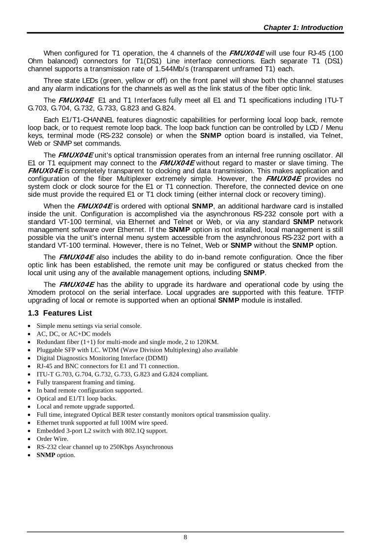
When configured for T1 operation, the 4 channels of the FMUX04E will use four RJ-45 (100 Ohm balanced) connectors for T1(DS1) Line interface connections. Each separate T1 (DS1) channel supports a transmission rate of 1.544Mb/s (transparent unframed T1) each.
Three state LEDs (green, yellow or off) on the front panel will show both the channel statuses and any alarm indications for the channels as well as the link status of the fiber optic link.
The FMUX04E E1 and T1 Interfaces fully meet all E1 and T1 specifications including ITU-T G.703, G.704, G.732, G.733, G.823 and G.824.
Each E1/T1-CHANNEL features diagnostic capabilities for performing local loop back, remote loop back, or to request remote loop back. The loop back function can be controlled by LCD / Menu keys, terminal mode (RS-232 console) or when the SNMP option board is installed, via Telnet, Web or SNMP set commands.
The FMUX04E unit's optical transmission operates from an internal free running oscillator. All E1 or T1 equipment may connect to the FMUX04E without regard to master or slave timing. The FMUX04E is completely transparent to clocking and data transmission. This makes application and configuration of the fiber Multiplexer extremely simple. However, the FMUX04E provides no system clock or clock source for the E1 or T1 connection. Therefore, the connected device on one side must provide the required E1 or T1 clock timing (either internal clock or recovery timing).
When the FMUX04E is ordered with optional SNMP, an additional hardware card is installed inside the unit. Configuration is accomplished via the asynchronous RS-232 console port with a standard VT-100 terminal, via Ethernet and Telnet or Web, or via any standard SNMP network management software over Ethernet. If the SNMP option is not installed, local management is still possible via the unit's internal menu system accessible from the asynchronous RS-232 port with a standard VT-100 terminal. However, there is no Telnet, Web or SNMP without the SNMP option.
The FMUX04E also includes the ability to do in-band remote configuration. Once the fiber optic link has been established, the remote unit may be configured or status checked from the local unit using any of the available management options, including SNMP.
The FMUX04E has the ability to upgrade its hardware and operational code by using the Xmodem protocol on the serial interface. Local upgrades are supported with this feature. TFTP upgrading of local or remote is supported when an optional SNMP module is installed.
1.3 Features List • Simple menu settings via serial console. • AC, DC, or AC+DC models • Redundant fiber (1+1) for multi-mode and single mode, 2 to 120KM. • Pluggable SFP with LC. WDM (Wave Division Multiplexing) also available • Digital Diagnostics Monitoring Interface (DDMI) • RJ-45 and BNC connectors for E1 and T1 connection. • ITU-T G.703, G.704, G.732, G.733, G.823 and G.824 compliant. • Fully transparent framing and timing. • In band remote configuration supported. • Optical and E1/T1 loop backs. • Local and remote upgrade supported. • Full time, integrated Optical BER tester constantly monitors optical transmission quality. • Ethernet trunk supported at full 100M wire speed. • Embedded 3-port L2 switch with 802.1Q support. • Order Wire. • RS-232 clear channel up to 250Kbps Asynchronous • SNMP option.

Chapter 1: Introduction
9
1.4 Packing List Upon opening your package, please check and be sure it contains the following items:
1. FMUX04E unit, AC, DC or AC+DC depending on modem ordered. 2. If AC power, a Clover Leaf to local power connector AC cable. 3. DB9M to DB9F “Y” cable for console configuration and alarm relay breakout. 4. RJ-45 to DB9M for RS-232 clear channel connection 5. User's Guide (hard copy or CDROM) 6. CDROM with MIB file (if SNMP option installed)
If any of these items are missing, please contact your distributor.
The following photo (AC model), with graphics, shows the major components which make up the FMUX04E (with the SNMP options installed).
Figure 1-1 : FMUX04E Major Components
E1 BNC Connectors
AC Power socket & Switch
Switching Power (AC)
Optical SFP cages
SNMP Module
Mainboard
E1 RJ45 Connectors
LED Indicators
Order Wire (ear-mic)
LCD Display
Menu Keys
Console & Alarm relay
DC-DC Power (DC)
DC Power terminal & Switch
LAN1/SNMP
LAN2
LAN3
RS-232

Chapter 1: Introduction
10
1.5 Technical Specifications
1.5.1 E1 Link Ports 4 fixed ports Framing Unframed (transparent) Bit Rate 2.048 Mb/s +/-50ppm Line Code AMI
HDB3 Line Impedance Unbalanced 75 ohms (BNC)
Balanced 120 ohms (RJ-45) Receiver sensitivity -12dB (short haul) "Pulse" Amplitude Nominal 2.37V+/-10% for 75 ohms
Nominal 3.00V+/-10% for 120 ohms "Zero" Amplitude +/-0.1V Transmit Frequency Tracking Recovery Timing
+/-50 ppm
Jitter Performance According to ITU-T G.823 recommendation Complies With ITU-T G.703 and G.823 recommendations Interface Connectors RJ-45 120 ohm (USOC RJ-48C)
BNC 75 ohm Test Loops LLB (Local Loop Back)
RLB (Remote Loop Back)
1.5.2 T1 Link Ports 4 fixed ports Framing Unframed (transparent) Bit Rate 1.544 Mb/s +/-50ppm Line Code AMI
B8ZS Line Impedance Balanced 100 ohms (RJ-45) Receiver sensitivity -12dB (short haul) "Pulse" Amplitude Nominal 3.00V+/-20% for 100 ohms "Zero" Amplitude +/-0.15V Transmit Frequency Tracking Recovery Timing
+/-50 ppm
Jitter Performance According to ITU-T G.824 recommendation Complies With ITU-T G.703 and G.824 recommendations Interface Connectors RJ-45 100 ohm (USOC RJ-48C) Test Loops LLB (Local Loop Back)
RLB (Remote Loop Back)
1.5.3 Ethernet Trunk Link Ports 3 fixed ports Connector RJ-45 (Auto MDI/MDIX) Standards IEEE 802.3, 802.3u, 802.1Q, 802.3x Supports 10Base-T, 100Base-TX, Full or Half Duplex MTU 1552 bytes, maximum packet size
1.5.4 RS-232 Clear Channel Interface RS-232 Async, up to 250K baud Connector RJ-45 (pin 1 SG, pin 2 data out, pin 3 data in)
1.5.5 RS-232 Console/Alarm Port Console Port local VT-100 terminal connection Port interface V.24/RS-232 asynchronous, DCE Port connector DB9 (female) Data rate (*default) 38400 bps Data format -One start bit
-8 data bits -No parity -One stop bit
DB9F Pin Usage Cable pin definition
DB9F(DCE) 5 GND 2 RX 3 TX
Alarm Relay contact Contact ratings: 1A at 30 VDC resistive or 0.5A at 125 VAC resistive
Pin 6 common 4 NO (*) 9 NC
* closed on alarm or closed if power fails or power is off
Chapter 1: Introduction
11
1.5.6 Order Wire
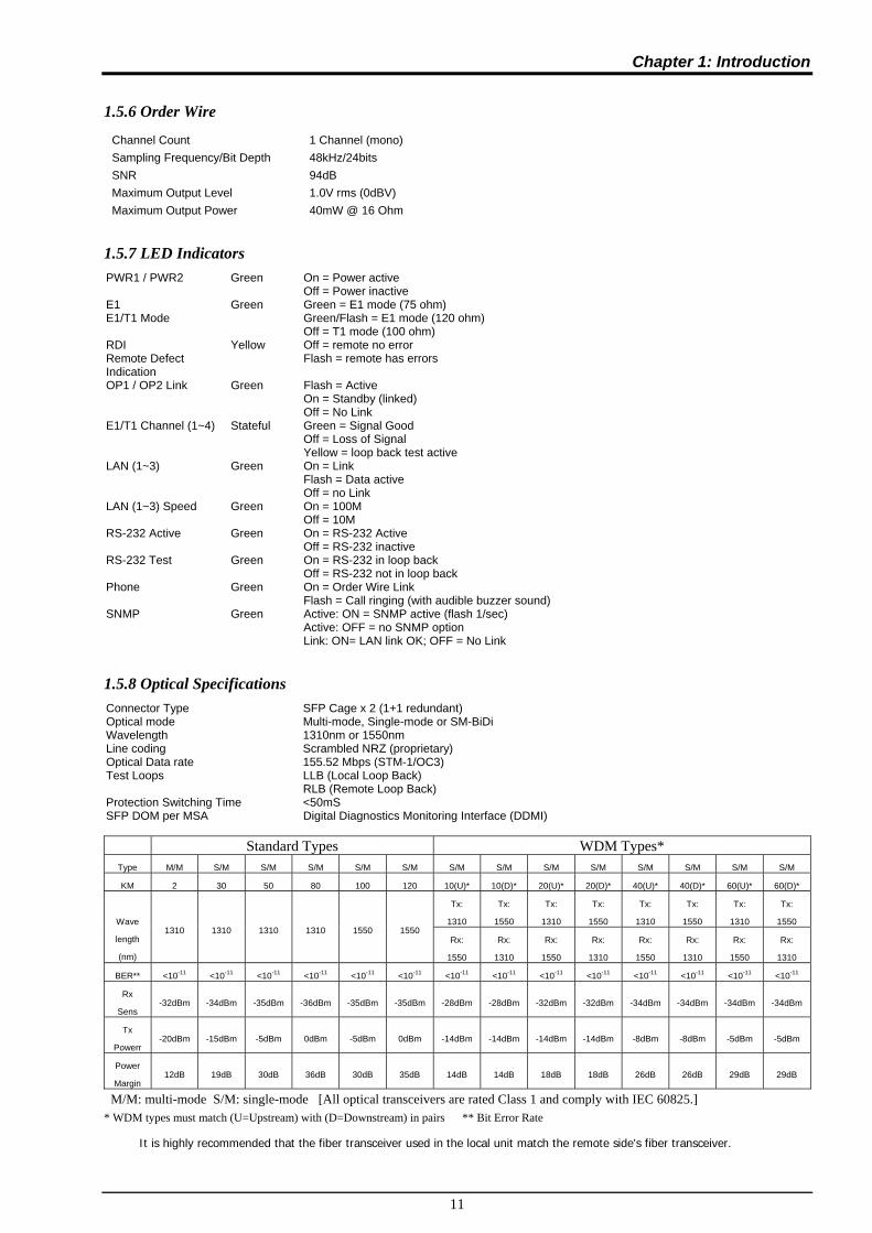
Channel Count 1 Channel (mono) Sampling Frequency/Bit Depth 48kHz/24bits SNR 94dB Maximum Output Level 1.0V rms (0dBV) Maximum Output Power 40mW @ 16 Ohm
1.5.7 LED Indicators PWR1 / PWR2 Green On = Power active
Off = Power inactive E1 E1/T1 Mode
Green Green = E1 mode (75 ohm) Green/Flash = E1 mode (120 ohm) Off = T1 mode (100 ohm)
RDI Remote Defect Indication
Yellow Off = remote no error Flash = remote has errors
OP1 / OP2 Link Green Flash = Active On = Standby (linked) Off = No Link
E1/T1 Channel (1~4) Stateful Green = Signal Good Off = Loss of Signal Yellow = loop back test active
LAN (1~3) Green On = Link Flash = Data active Off = no Link
LAN (1~3) Speed Green On = 100M Off = 10M
RS-232 Active Green On = RS-232 Active Off = RS-232 inactive
RS-232 Test Green On = RS-232 in loop back Off = RS-232 not in loop back
Phone Green On = Order Wire Link Flash = Call ringing (with audible buzzer sound)
SNMP Green Active: ON = SNMP active (flash 1/sec) Active: OFF = no SNMP option Link: ON= LAN link OK; OFF = No Link
1.5.8 Optical Specifications Connector Type SFP Cage x 2 (1+1 redundant) Optical mode Multi-mode, Single-mode or SM-BiDi Wavelength 1310nm or 1550nm Line coding Scrambled NRZ (proprietary) Optical Data rate 155.52 Mbps (STM-1/OC3) Test Loops LLB (Local Loop Back)
RLB (Remote Loop Back) Protection Switching Time <50mS SFP DOM per MSA Digital Diagnostics Monitoring Interface (DDMI)
Standard Types WDM Types* Type M/M S/M S/M S/M S/M S/M S/M S/M S/M S/M S/M S/M S/M S/M
KM 2 30 50 80 100 120 10(U)* 10(D)* 20(U)* 20(D)* 40(U)* 40(D)* 60(U)* 60(D)*
Tx:
1310
Tx:
1550
Tx:
1310
Tx:
1550
Tx:
1310
Tx:
1550
Tx:
1310
Tx:
1550
Wave
length
(nm)
1310 1310 1310 1310 1550 1550 Rx:
1550
Rx:
1310
Rx:
1550
Rx:
1310
Rx:
1550
Rx:
1310
Rx:
1550
Rx:
1310
BER** <10-11 <10-11 <10-11 <10-11 <10-11 <10-11 <10-11 <10-11 <10-11 <10-11 <10-11 <10-11 <10-11 <10-11
Rx
Sens -32dBm -34dBm -35dBm -36dBm -35dBm -35dBm -28dBm -28dBm -32dBm -32dBm -34dBm -34dBm -34dBm -34dBm
Tx
Powerr -20dBm -15dBm -5dBm 0dBm -5dBm 0dBm -14dBm -14dBm -14dBm -14dBm -8dBm -8dBm -5dBm -5dBm
Power
Margin 12dB 19dB 30dB 36dB 30dB 35dB 14dB 14dB 18dB 18dB 26dB 26dB 29dB 29dB
M/M: multi-mode S/M: single-mode [All optical transceivers are rated Class 1 and comply with IEC 60825.] * WDM types must match (U=Upstream) with (D=Downstream) in pairs ** Bit Error Rate
It is highly recommended that the fiber transceiver used in the local unit match the remote side's fiber transceiver.

Chapter 1: Introduction
12
1.5.9 Physical
Height: 43 mm (1.75") Width: 215 mm (8.5") Depth: 248 mm (9.75") Weight: 1590 g (3 lb. 8 oz.) Net
1625 g (3 lb. 9 oz.) including SNMP
1.5.10 Power supply
Voltage (AC source) 100 ~ 240 VAC +/-10% Frequency 47 to 63 Hz for AC power Voltage (DC source) 18 ~ 75 VDC Power consumption 15 VA maximum
1.5.11 Environment (Operating)
Temperature 0-60° C / 32-140° F Humidity 5 to 95% non-condensing
1.5.12 Miscellaneous
MTBF 75,000 hours Emission & Safety compliance meets FCC part 15 Sub B (class A)
EN55022:2006, Class A IEC61000-3-2:2005, 61000-3-3:2005, EN55024:1998+A1:2001+A2:2003 and EN60950-1:2001
1.6 E1 Signal Structure
1.6.1 E1 link line rate and coding
The E1 line operates at a nominal rate of 2.048Mb/s.
The basic E1 line signal is coded using either the Alternate Mark Inversion (AMI) or HDB3 rule. In the AMI format, "ones" are alternately transmitted as positive and negative pulses, whereas "zeros" are transmitted as a zero voltage level. AMI is not used in most 2.048Mb/s transmissions because synchronization loss occurs during long strings of data zeros.
In the HDB3 format, a string of four consecutive zeros is replaced with a substitute string of pulses containing an intentional bipolar violation. The HDB3 code substitutions provide high pulse density so that the receiving equipment is able to maintain synchronization with the received signal.
When configured for E1, the 4-CHANNEL E1 Ports support one of two E1 line codes:
AMI coding.
HDB3 coding.
The 4-CHANNEL E1 Ports are completely transparent and support any frame format. i.e. The E1 will pass through with its original framing structure completely intact.

Chapter 1: Introduction
13
1.7 T1(DS1) Signal Structure
1.7.1 T1 link line rate and coding
The T1 line operates at a nominal rate of 1.544Mb/s.
The basic T1 line signal is coded using either the Alternate Mark Inversion (AMI) or B8ZS rule. In the AMI format, "ones" are alternately transmitted as positive and negative pulses, whereas "zeros" are transmitted as a zero voltage level. AMI is not used in most 1.544Mb/s transmissions because synchronization loss occurs during long strings of data zeros.
In the B8ZS format, a string of eight consecutive zeros is replaced with a substitute string of pulses containing an intentional bipolar violation. The B8ZS code substitutions provide high pulse density so that the receiving equipment is able to maintain synchronization with the received signal.
When configured for T1, the 4-CHANNEL T1 Ports support one of two T1 line codes:
AMI coding.
B8ZS coding.
The 4-CHANNEL T1 Ports are completely transparent and support any frame format. i.e. The T1 will pass through with its original framing structure completely intact.

Chapter 1: Introduction
14
1.8 Applications / Capabilities
In the following example, the FMUX04E utilizes an optical fiber connection between a pair of units to provide 4channels of E1 or T1, 100M Ethernet, RS-232 clear channel and bi-directional audio (Order Wire) between the units. The timing scheme for typical E1 or T1 equipment is to transparently pass timing from a timing source unit on one side, to a timing slaved unit on the other. Each of the up to 4 available channels of the FMUX04E is independent of any other channel for transparent framing or timing.
Figure 1-2 : Typical Point-to-Point Application of FMUX04E

Chapter 2. Installation
15
Chapter 2. Installation
2.1 General
The Installation chapter will cover the physical installation of the FMUX04E, Standalone/Rack Mount Fiber Optical Multiplexer, the electrical connections, interface connections and cabling requirements. A brief overview of the functional components such as main unit and management options will also be outlined in this chapter. Required Tools You will need these tools to install the FMUX04E: Number 2 Phillips screwdriver for the 3mm and the 12-24 rack installation screws. Wrist strap or other personal grounding device to prevent ESD occurrences. Antistatic mat or antistatic foam to set the equipment on.
2.2 Site Preparation
Install the FMUX04E within reach of an easily accessible grounded AC outlet or site DC power. The outlet should be capable of furnishing 100 to 240 VAC (18 to 36VDC or 36 to 72 VDC for DC supply). Allow at least 10cm (4 inch) clearance at the rear and front of the FMUX04E for power lines and interface cables.
2.3 Unpacking
Figure 2-1. Unpacking the FMUX04E.
Inner cover
Unit
Cables
Outer cover

Chapter 2. Installation
16
2.4 Mechanical Assembly
The FMUX04E is designed for standalone use, but it may be rack mounted as required with an optional mounting kit. The rack installation only requires 1U space (1.75") in a standard EIA 19 inch rack. The FMUX04E is delivered completely assembled. No provision is made for bolting the FMUX04E to a tabletop.
Figure 2-2. Single and tandem rack mounting of FMUX04E.

Chapter 2. Installation
17
2.5 Electrical Installation
2.5.1 Power connection, AC
For a model with AC power supply, AC power (100~240VAC) is supplied to the FMUX04E through a IEC C6 3-prong receptacle, located on the rear of the unit. The FMUX04E should always be grounded through the protective earth lead of the power cable in AC installations.
2.5.2 Power connection, DC
For a model with DC power supply, DC (18~75VDC) is connected to the terminal block. The DC power connector uses a fixed terminal block. Please take extra caution to observe the proper polarity of the DC when wiring the connector. The FMUX04E should always be grounded through the protective earth lead via the frame ground connection for DC installations.
2.5.3 Power connection, AC+DC
The AD model provides both AC and DC inputs and can be used separate or together.
Figure 2-3 : Supply connections, AC+DC model shown
2.6 Rear Panel Connectors
The rear panel of the FMUX04E supports the E1 and T1 interface connections, the AC or DC power connectors and the power switch(es). The FMUX04E routes the signals from the 4 E1/T1 channels to the multiplexing circuitry and sends the multiplexed signals to the aggregate Fiber Interfaces on the front panel.
Figure 2-4 : Rear Panel Connections
Unbalanced E1
Balanced E1/T1
RS-232 Clear Channel
10/100M Ethernet
AC Input DC Input

Chapter 2. Installation
18
2.7 Front Panel Switches, Connectors and Indicators
Located on the front panel of the FMUX04E, are the SFP optical interface cages, the LCD display and menu keys, the LED display and the RS-232 Console port/Alarm Relay connector (DB9F). The optical interfaces utilize industry standard SFP modules. The FMUX04E supports single mode or multimode SFP transceivers with 155M data rate or Multi-rate SFPs in powers that support 2, 30, 50, 80 or 120KM reach. The front panel also provides the Order Wire jacks that can directly connect to any standard microphone / headset using 3.5mm phone jacks.
Figure 2-5 : Front Panel Controls and Indicators
2.8 SNMP Removal/Replacement Procedures ***CAUTION*** This procedure should only be performed by qualified service personnel. In addition, all power connections must be removed before attempting to open the case. All work should be done on a properly grounded anti-static map and personnel should be wearing an approved ESD grounding wrist strap.
1. If the unit is installed in a rack, remove all connections and power cord. Remove the unit from the rack.
2. Remove the four (4) cover screws on the sides of the FMUX04E and lift off the cover.
3. If initially installing, remove the SNMP module PCBA from its protective ESD wrapping. Refer to the graphic on page 9 for the location of the SNMP option.
3. Align the connector pins as in the following photos, seat the module, insert the three securing screws, and tighten lightly.
4. Return the cover and cover screws. The unit is now ready to configure and use.
Figure 2-6 : SNMP daughter card Install / Removal / Replacement Note: Follow the instructions in Chapter 4 SNMP to configure the SNMP option.
Align the Connector
LCD / Menu Keys
Optical (SFP)
Order wire
Terminal (NMS) and Alarm Relay
LED Display
Screw
Screw
Screw

Chapter 3. Operation
19
Chapter 3. Operation
3.1 Introduction
This chapter will go into the details of the specific configuration and operation of the FMUX04E by using a VT-100 terminal connected to the RS-232 Console port and via the front panel LCD/Menu keys.
3.2 Terminal Mode Operation
A notebook computer has become an invaluable tool of the Systems Engineer. Connection between the computer and the FMUX04E is very straight forward. The only hardware required is a DB9M to DB9F adapter cable (see pinout below). The FMUX04E's RS-232 Console port acts as a DCE to the PC's DTE communications port. A convenient application, provided with the Microsoft Windows® 98/NT/2K/XP operating systems, is "HyperTerminal™". The settings for console port communication with the FMUX04E are 38.4K baud, 8 bits, no parity, 1 stop bit and no flow control. In the HyperTerminal program terminal window click the "properties" icon and set the communication parameters as in the following graphics. Click the "Configure…" button in the properties window and set the port settings. When set properly, click "OK".
Figure 3-1 HyperTerminal port settings for FMUX04E
3.3 Connecting to the FMUX04E
The console port on the FMUX04E is an RS-232 interface (DCE) that utilizes a DB9 connector. Use the configuration cable that is supplied with the FMUX04E or prepare a three wire DB9(F) to DB9(M) cable with the following pin out:
DB9(M) signal DB9(F) 5 GND 5 2 TD 2 3 RD 3

Chapter 3. Operation
20
3.4 Configuring in Console Mode
The FMUX04E Control Port (labeled Console / Alarm on the front panel) is a console terminal port designed to facilitate setup of all parameters through the use of a standard text based terminal or any terminal emulation program running on a Personal Computer. Make the appropriate connections, start the terminal application, apply power to the FMUX04E. The ‘password’ prompt will be displayed on the screen. The factory default password is blank, just press [Enter].
3-2 Terminal Connection
3.4.0 Local Login
Enter the password and press ENTER on the PC keyboard. If you are using "HyperTerminal™" the display should look like the following. Just below the main header, we find the [Local] shown in brackets. This is the main menu for the local unit. The Version explanation for the example shown here is PCB h/w version 1.200, s/w version 1.000, CPLD version 0.000 (or none) and FPGA version 0.500. Device: Shows the power status, can enable or disable device, and can execute a factory default. Fiber: Shows optical working status, enable/disable, loop back, ALS and DD function display. E1/T1: Provides the mode, line code and loopback settings plus service enable/disable for E1/T1. LAN: Shows LAN port connection status, port enable/disable, plus auto/forced mode settings. RS-232: Shows status of RS-232 clear channel, provides enable/disable plus loopback function. Phone: Provides enable/disable service and call activation via menu (software). SNMP: This menu provides the TCP/IP settings for the SNMP agent; IP, gateway and subnet mask. Management: Setup the allowed managers and trap destinations by IP and community string. Password: Allows setting up a console login password. If the password is forgotten, contact CTC Union support for the password recovery procedure. Switch to Remote Menu: The ‘Have’ indicated there is a fiber connected remote. Use ‘T’ to toggle between the remote and local menus.
**************************************** *** CTC UNION TECHNOLOGIES CO.,LTD *** *** FMUX04E Manager Ver:1.00 *** **************************************** [Local ] Version:[1.200-1.000-0.000-0.500] [No SNMP ] <1> Device Status and Configuration <2> Fiber Status and Configuration <3> E1/T1 Status and Configuration <4> LAN Status and Configuration <5> RS232 Status and Configuration <6> Phone Status and Configuration <7> SNMP Agent Configuration <8> Management Configuration <P> Setting Password <T> Switch To Remote Menu [Present] Please select an item.
**************************************** *** CTC UNION TECHNOLOGIES CO.,LTD *** *** FMUX04E Manager Ver:1.00 *** **************************************** Password :
Enter password if set

Chapter 3. Operation
21
3.4.1 Device
Reach the ‘Device’ menu by pressing [1] at the main menu for either local or remote The above example unit has dual power supplies. PWR1 is AC and PWR2 is DC. If no input voltage is connected to a power supply, it will show the message ‘Fail’. For single power supply model, one power will be ‘OK’ and the other will be ‘NI’ (Not Installed). The first menu item “Device Service” provides a software method to disable all traffic from this device. IMPORTANT: Although the remote unit has this menu item, it is not functional. You cannot disable the remote unit because doing so would result in loss of remote management. The second item, “Default Configuration”, is a quick way to return the unit to factory defaults. The default is all ports enabled and E1 mode with 75 Ohm impedance setting for BNC.
3.4.2 Fiber
Reach the ‘Fiber’ menu by pressing [2] at the main menu for either local or remote Just below the header and ‘Version’ fields we find the “Fiber Status and Configuration” info. Fiber Link: There is at least one active link between this unit and the remote when indication is “Up” Remote PWR: In a normal condition the status will be “OK”. If the remote unit suffers a power loss, the ‘dying gasp’ mechanism will let the local unit know and the status will be displayed as “Abnormal”. OP1 Rx Link: The Optical 1 port shows “Up” status when receiving optical signal. OP2 Rx Link: The Optical 2 port shows “Up” status when receiving optical signal. Small Form Pluggable: When an SFP is installed in the cage the status will be “Yes”. If SFP is installed it will be “No”. DD Function: If the SFP includes DOM function, the status will be indicated here with a “Yes”. <1> Fiber Working Channel: The working channel status is displayed here and the menu item allows selecting the working channel manually.
**************************************** *** CTC UNION TECHNOLOGIES CO.,LTD *** *** FMUX04E Manager Ver:1.00 *** **************************************** [Local ] Version:[1.200-1.000-0.000-0.500] [No SNMP ] << Device Status and Configuration >> PWR1 [ OK ] PWR2 [ OK ] <1> Device Service [ On ] <2> Default Configuration <ESC> Go to previous menu. Please select an item.
**************************************** *** CTC UNION TECHNOLOGIES CO.,LTD *** *** FMUX04E Manager Ver:1.00 *** **************************************** [Local ] Version:[1.200-1.000-0.000-0.500] [No SNMP ] << Fiber Status and Configuration >> Fiber Link [ Up ] Remote PWR [ OK ] OP1 Rx Link [ Up ] OP2 Rx Link [ Up ] OP1 Small Form Pluggable:[ Yes ] Digital Diagnostic Function:[ No ] OP2 Small Form Pluggable:[ Yes ] Digital Diagnostic Function:[ No ] <1> Fiber Working Channel Working [ OP1 ] Standby [ OP2 ] <2> Loop Back Test Mode [ Disable ] <3> Auto Laser Shutdown [ Disable ] <4> Go to the OP1 D/D Function menu. <5> Go to the OP2 D/D Function menu. <ESC> Go to previous menu. Please select an item.
Chapter 3. Operation
22
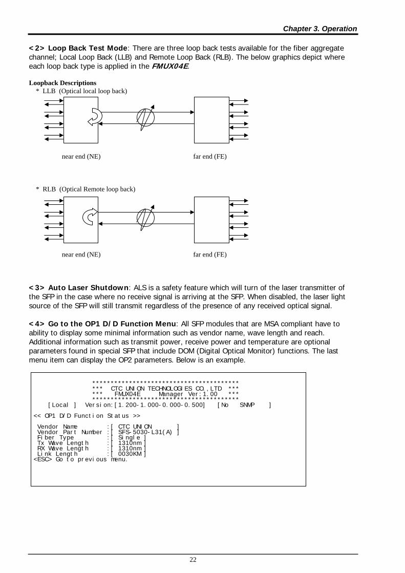
<2> Loop Back Test Mode: There are three loop back tests available for the fiber aggregate channel; Local Loop Back (LLB) and Remote Loop Back (RLB). The below graphics depict where each loop back type is applied in the FMUX04E. Loopback Descriptions * LLB (Optical local loop back) near end (NE) far end (FE) * RLB (Optical Remote loop back) near end (NE) far end (FE) <3> Auto Laser Shutdown: ALS is a safety feature which will turn of the laser transmitter of the SFP in the case where no receive signal is arriving at the SFP. When disabled, the laser light source of the SFP will still transmit regardless of the presence of any received optical signal. <4> Go to the OP1 D/D Function Menu: All SFP modules that are MSA compliant have to ability to display some minimal information such as vendor name, wave length and reach. Additional information such as transmit power, receive power and temperature are optional parameters found in special SFP that include DOM (Digital Optical Monitor) functions. The last menu item can display the OP2 parameters. Below is an example.
**************************************** *** CTC UNION TECHNOLOGIES CO.,LTD *** *** FMUX04E Manager Ver:1.00 *** **************************************** [Local ] Version:[1.200-1.000-0.000-0.500] [No SNMP ] << OP1 D/D Function Status >> Vendor Name :[ CTC UNION ] Vendor Part Number :[ SFS-5030-L31(A) ] Fiber Type :[ Single ] Tx Wave Length :[ 1310nm ] RX Wave Length :[ 1310nm ] Link Length :[ 0030KM ] <ESC> Go to previous menu.

Chapter 3. Operation
23
3.4.3 E1/T1
Reach the ‘E1/T1’ menu by pressing [3] at the main menu for either local or remote 3.4.3.1 Type Choose menu item [1] to setup the ‘Type’ between E1/75 Ohm, E1/120 Ohm or T1/100 Ohm. 3.4.3.2 Configuration Choose menu items [2-5] to setup the E1/T1 Line Coding and Loop Back Functions. <1> E1/T1 Service: Use this menu selection to disable E1 or T1 service on the affected channel. <2> Line Code: E1 settings support AMI or HDB3 (default) line coding while T1 settings support AMI or B8ZS (default) line coding.
**************************************** *** CTC UNION TECHNOLOGIES CO.,LTD *** *** FMUX04E Manager Ver:1.00 *** **************************************** [Local ] Version:[1.200-1.000-0.000-0.500] [No SNMP ] << E1/T1 Status and Configuration >> <1> E1/T1 Termination Type [ E1/120/RJ45 ] <2> E1/T1 Channel 1 Status and Configuration <3> E1/T1 Channel 2 Status and Configuration <4> E1/T1 Channel 3 Status and Configuration <5> E1/T1 Channel 4 Status and Configuration <ESC> Go to previous menu. Please select an item.
**************************************** *** CTC UNION TECHNOLOGIES CO.,LTD *** *** FMUX04E Manager Ver:1.00 *** **************************************** [Local ] Version:[1.200-1.000-0.000-0.500] [No SNMP ] << E1/T1 Status and Configuration >> <1> E1/T1 Termination Type [ E1/120/RJ45 ] <2> E1/T1 Channel 1 Status and Configuration <3> E1/T1 Channel 2 Status and Configuration <4> E1/T1 Channel 3 Status and Configuration <5> E1/T1 Channel 4 Status and Configuration ---------------------------------------------------------------------- E1/T1 Termination Type : <1>: E1/75/BNC <2>: E1/120/RJ45 <3>: T1/100/RJ45 <ESC> Go to previous menu. Please select an item.
**************************************** *** CTC UNION TECHNOLOGIES CO.,LTD *** *** FMUX04E Manager Ver:1.00 *** **************************************** [Local ] Version:[1.200-1.000-0.000-0.500] [No SNMP ] << E1/T1 Channel 1 Status and Configuration >> Termination Type [ E1/120/RJ45] Link [ Up ] <1> E1/T1 Service [ On ] BVP Error[ normal ] <2> Line Code [ HDB3 ] <3> Loop Back Test Mode [ Disable ] <ESC> Go to previous menu. Please select an item.

Chapter 3. Operation
24
<3> Loop Back Test Mode: There are three loop back tests available for the E1/T1 tributary channels; Local Loop Back (LLB) and Remote Loop Back (RLB). The below graphics depict where each loop back type is applied in the FMUX04E. Loopback Descriptions * LLB (E1/T1 local loop back) near end (NE) far end (FE) This local loop back will make the near end unit loop towards the copper side's channel. * RLB (E1/T1 Remote loop back) near end (NE) far end (FE) This remote loop back will loop the logical channel from the near end unit back to the far end unit via the fiber.
3.4.4 LAN
Reach the ‘LAN’ menu by pressing [4] at the main menu for either local or remote <1> Operation Mode: In the “No VLAN” mode, the three LAN ports and the SNMP agent (if installed) are all connected by switch to the aggregate trunk. In “Port 1 VLAN” mode, the LAN/SNMP port connects only to the SNMP agent for out-band management and does not connect to the aggregate trunk or to LAN2 or LAN3 ports.
**************************************** *** CTC UNION TECHNOLOGIES CO.,LTD *** *** FMUX04E Manager Ver:1.00 *** **************************************** [Local ] Version:[1.200-1.000-0.000-0.500] [No SNMP ] << LAN Status and Configuration >> <1> Operation Mode [ No VLAN ] <2> LAN Channel 1 Status and Configuration <3> LAN Channel 2 Status and Configuration <4> LAN Channel 3 Status and Configuration <ESC> Go to previous menu. Please select an item.

Chapter 3. Operation
25
<2-4> LAN Channel x Status and Configuration: These three menu items [2-4] are for each on the LAN ports. Under these menus, services can be disable and the Ethernet can be configured for auto-negotiation (default) or to one of four forced modes; 100/Full, 100/Half, 10/Full or 10/Half. <1> LAN Service: Disable or enable this port and view the link state. <2> Negotiation: The default switch setting is with auto-negotiation enabled. Auto-negotiation is defined in the IEEE802.3u standard for Fast Ethernet. If a connected device also supports auto-negotiation, they will connect automatically at 100Base-TX Full Duplex. If the device connected to the FMUX04E LAN port does not support auto-negotiation, either because it is in a forced mode or if it is legacy equipment that does not support auto-negotiation, this port on the FMUX04E will fail negotiation and assume Half Duplex mode. Please be very careful when connecting auto to forced devices or when setting this device to forced and connecting to an auto device. Duplex Mismatch may result and cause poor performance and eventual traffic block. Speed between 10Base and 100Base is auto detected, but duplex must be negotiated. Remote Duplex setting cannot be auto detected. <3> Speed: Set the port speed and view the current status. Speed can be manually set (forced) only when auto-negotiation is disabled (see item 2). <4> Duplex: Set the port Duplex and view the current status. The Duplex can be manually set (forced) only when auto-negotiation is disabled (see item 2).
3.4.5 RS-232
Reach the ‘RS-232’ menu by pressing [5] at the main menu for either local or remote <1> RS-232 Service: Disable or enable this port and view the link state. <2> RS-232 Loop Back Test Mode: There are two loop back tests available for the RS-232 tributary clear channel; Local Loop Back (LLB) and Remote Loop Back (RLB).
**************************************** *** CTC UNION TECHNOLOGIES CO.,LTD *** *** FMUX04E Manager Ver:1.00 *** **************************************** [Local ] Version:[1.200-1.000-0.000-0.500] [No SNMP ] << LAN Channel 1 Status and Configuration >> <1> LAN Service [ On ] Link [ Up ] <2> Negotiation [ Auto ] <3> Speed [ 100 ] Status[ 100 ] <4> Duplex [ Full ] Status[ Full ] <ESC> Go to previous menu. Please select an item.
**************************************** *** CTC UNION TECHNOLOGIES CO.,LTD *** *** FMUX04E Manager Ver:1.00 *** **************************************** [Local ] Version:[1.200-1.000-0.000-0.500] [No SNMP ] << RS-232 Status and Configuration >> <1> RS-232 Service [ On ] Rx Active [ Off ] <2> RS-232 Loop Back Test Mode [ Disable ] <ESC> Go to previous menu. Please select an item.

Chapter 3. Operation
26
3.4.6 Phone (Order Wire)
Reach the ‘Phone’ menu by pressing [6] at the main menu for either local or remote <1> Phone Service: Disable or enable this port and view the link state. <2> Phone Call Out: This will initiate a manual ‘call’ function, ringing the buzzer at the remote side.
3.4.7 Password
Physical security is the best and front line protection for any networking device. In data centers, only authorized personal should have access to facilities. Equipment closets and cabinets not within a secure data center should have locking mechanisms. The FMUX04E includes another level of tamper protection with the ability to set a four digit password code. Once set, this code is required to access the front panel LCD or to login to the menu system by console management port. Password code can be any digit from 0000 to 9999. To clear the password, leave it null (blank) when doing a password modify. If the password is ever forgotten, contact CTC Union support for the password recovery procedure. This is the main "LOCAL" root menu that will be displayed after login. From the main menu, press [p], key-in the old password and then the new password twice. Simply pressing [Enter] for the new password will enter a null. With a null password set, the login can be skipped just by pressing [Enter] at the console or LCD keyboard.
****************************************
*** CTC UNION TECHNOLOGIES CO.,LTD ***
*** FMUX04E Manager Ver:1.00 ***
****************************************
[Local ] Version:[1.200-1.000-0.000-0.500] [No SNMP ]
<1> Device Status and Configuration
<2> Fiber Status and Configuration
<3> E1/T1 Status and Configuration
<4> LAN Status and Configuration
<5> RS232 Status and Configuration
<6> Phone Status and Configuration
<7> SNMP Agent Configuration
<8> Management Configuration
<P> Setting Password
<T> Switch To Remote Menu [ Have ]
Please select an item.
----------------------------------------------------------------------
Old Password :******
New Password :******
Re Password :******
**************************************** *** CTC UNION TECHNOLOGIES CO.,LTD *** *** FMUX04E Manager Ver:1.00 *** **************************************** [Local ] Version:[1.200-1.000-0.000-0.500] [No SNMP ] << Phone Status and Configuration >> <1> Phone Service [ On ] <2> Phone Call Out <ESC> Go to previous menu. Please select an item.

Chapter 3. Operation
27
3.4.8 Remote
From the main menu, use the [T] key to view the menu for the remote fiber connected unit. When the status of the remote is “Present”, it is available for remote configuration. If the status is “Absent”, there is no remotely connected device and no remote management available. The following is an example of the remote configuration screen. The 'Main' menu is the gateway to doing all configuration of the FMUX04E. From the main menu, the Device, Fiber Optical, E1/T1, LAN, RS-232, order wire, SNMP and management setting menus can be selected. In addition, the remote unit can be accessed to perform all the same settings as with the local unit.
3.5 Configuring via the LCD/Menu The FMUX04E features a backlit 12 character by 2 row LCD (Liquid Crystal Display) for local/remote control and management without the need for any other equipment. There are 4 pushbuttons for maneuvering the menu system, browsing parameters and making settings. The [Enter] key selects a deeper menu or confirms a selected parameter. The [Left] and [Right] arrow keys move between the vertical menu items or between the available parameters. The [ESC] key backs out of the menu one step at a time.
3.5.1 Menu Structure
Local Cfg ‐‐‐‐‐‐‐‐‐‐‐‐‐‐‐‐‐‐‐ Remote Cfg +‐‐ Optical | +‐‐‐ Working ‐‐‐ [On/Off] | +‐‐‐ Loop Back ‐ [LLB/RLB] | +‐‐‐ ALS ‐‐‐‐‐‐‐ [Enable/Disable] +‐‐ E1/T1 | +‐‐‐ Type ‐‐‐‐‐‐ [E1(75)/E1(120)/T1(100)] | +‐‐‐ Ch1~4 | +‐‐‐‐‐‐‐ Service ‐‐‐ [On/Off] | +‐‐‐‐‐‐‐ Line Code ‐ [HDB3(B8ZS)/AMI] | +‐‐‐‐‐‐‐ Loop Back ‐ [LLB/RLB] +‐‐ LAN 1~3 | +‐‐‐ Service ‐‐‐ [On/Off] | +‐‐‐ Negotiation [Auto/Manual] | +‐‐‐ Speed ‐‐‐‐‐ [10Base/100Base] | +‐‐‐ Duplex ‐‐‐‐ [Full/Half] +‐‐ RS‐232 | +‐‐‐ Service ‐‐‐ [On/Off] | +‐‐‐ Loop Back ‐ [LLB/RLB] +‐‐ Phone +‐‐‐ Service ‐‐‐ [On/Off] +‐‐‐ Call ‐‐‐‐‐‐ [On]
****************************************
*** CTC UNION TECHNOLOGIES CO.,LTD ***
*** FMUX04E Manager Ver:1.00 ***
****************************************
[Remote] Version:[1.200-1.000-0.000-0.500] [No SNMP ]
<1> Device Status and Configuration
<2> Fiber Status and Configuration
<3> E1/T1 Status and Configuration
<4> LAN Status and Configuration
<5> RS232 Status and Configuration
<6> Phone Status and Configuration
<T> Switch To Local Menu
Please select an item.

Chapter 3. Operation
28
3.5.2 Operation detail
The 12 character by 2 line LCD is located plainly on the front panel. To its right are the 4 menu keys.
1. The [-Left] and [Right+] arrow keys move between the vertical menu items or between the selections of available parameters. When entering a password, these keys increment and decrement the number at the cursor position.
2. The [ESC] key backs out of the menu one step at a time. 3. The [ENT] key selects a deeper menu or confirms a selected parameter.
Initial Display
F M U X 0 4 E
V 1 . 0 0 [ _ _ _ _ ]
This is the initial display which shows the model name and software version. Four space fields are used to enter the password, if it has been set. The unit ships from the factory without any password. Pressing [ENT] key will enter the Local Cfg menu.
F M U X 0 4 E M e n u
L o c a l c f g
The top menu items for local configuration include the Optical, E1/T1, LAN, RS-232 and Phone. Press [ENT] to enter the top menu, starting at the Optical settings.
L o c a l c f g
O p t i c a l
Optical From this top level menu, pressing the [Right+] arrow key will browse to the other top menu items; E1/T1, LAN, RS-232 and Phone. Pressing [ENT] at this item will enter the setting menu for the Optical interfaces.
O p t i c a l
W o r k i n g C h
The first item is the ‘working channel’. If two SFP are installed and both linked, the working channel can be set between either ‘OP1’ or ‘OP2’ optical ports. If only one SFP is installed, the unit will only work when that link is good and that will be the ‘working channel’.

Chapter 3. Operation
29
E1/T1 The parameter settings under E1/T1 include first the type, which is defined for all four channels and can be E1/75 Ohm (BNC), E1/120 Ohm (RJ-45) or T1/100 Ohm (RJ-45). All four channels must work the same ‘type’. Next, each individual channel (CH1~CH4) can set Service, Line Code and Loop Back.
E 1 / T 1
E 1 / T 1 t y p E
The Type could be E1 120 ohm, E1 75 ohm or T1 100 ohm.
E 1 / T 1
C h a n n e l 1
Each channel can set service enabled or disabled, set the line code and do loop back.
C h a n n e l 1
L i n e c o d e
The channel can select between HDB3/B8ZS or AMI line coding.
L i n e c o d e
H D B 3 / B 8 Z S
LAN
L A N 1
S e r v i c e
Each of three LAN ports can set service on/off and configure the Ethernet port for auto negotiation or for manual forced mode. In forced mode both speed (10 or 100) and Duplex (Full or Half) can be forced set with no auto negotiation. RS-232
R S 2 3 2
S e r v i c e
The clear channel RS-232 port on RJ-45 can configure the service on/off and can also provide local and remote loop back. Phone
P h o n e
S e r v i c e
The phone can enable or disable service. Calls can be made manually by pressing the ‘Call’ button on the front panel. A typical microphone/headset for laptop voice instant messaging can be used for order wire service. Plug the 3.5mm phone plugs into the appropriately labeled jacks on the front face of the FMUX04E. Pressing [ESC] key repeatedly will back out from any menu and eventually back to the first initial display screen. Using the LCD will let you quickly master the settings of the FMUX04E.
Chapter 3. Operation
30
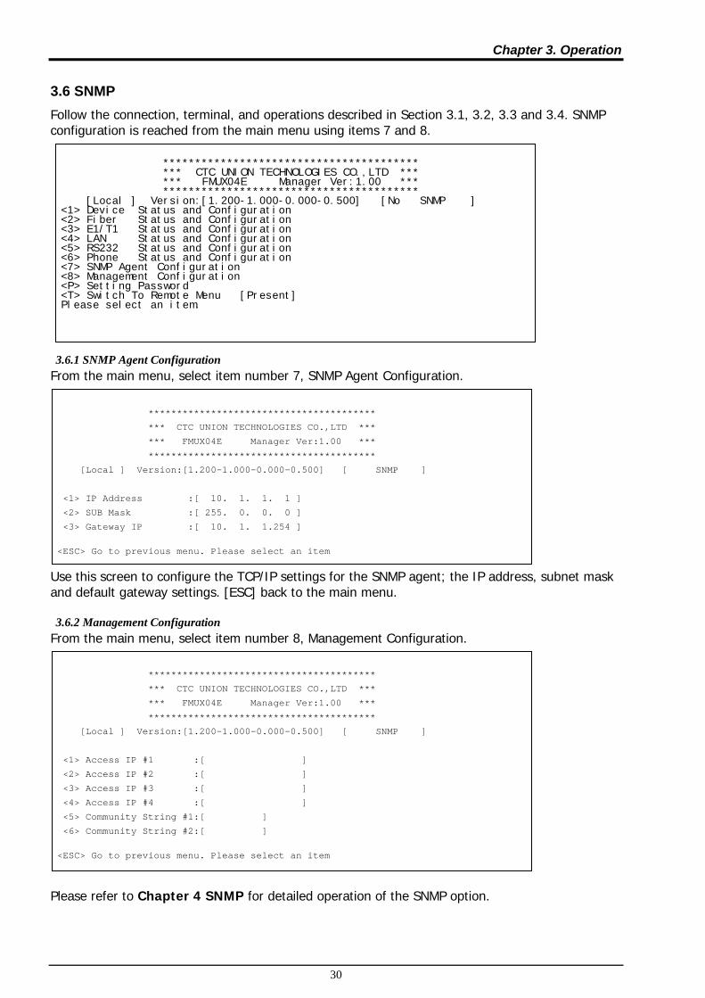
3.6 SNMP Follow the connection, terminal, and operations described in Section 3.1, 3.2, 3.3 and 3.4. SNMP configuration is reached from the main menu using items 7 and 8. 3.6.1 SNMP Agent Configuration
From the main menu, select item number 7, SNMP Agent Configuration. Use this screen to configure the TCP/IP settings for the SNMP agent; the IP address, subnet mask and default gateway settings. [ESC] back to the main menu. 3.6.2 Management Configuration
From the main menu, select item number 8, Management Configuration. Please refer to Chapter 4 SNMP for detailed operation of the SNMP option.
**************************************** *** CTC UNION TECHNOLOGIES CO.,LTD *** *** FMUX04E Manager Ver:1.00 *** **************************************** [Local ] Version:[1.200-1.000-0.000-0.500] [No SNMP ] <1> Device Status and Configuration <2> Fiber Status and Configuration <3> E1/T1 Status and Configuration <4> LAN Status and Configuration <5> RS232 Status and Configuration <6> Phone Status and Configuration <7> SNMP Agent Configuration <8> Management Configuration <P> Setting Password <T> Switch To Remote Menu [Present] Please select an item.
****************************************
*** CTC UNION TECHNOLOGIES CO.,LTD ***
*** FMUX04E Manager Ver:1.00 ***
****************************************
[Local ] Version:[1.200-1.000-0.000-0.500] [ SNMP ]
<1> IP Address :[ 10. 1. 1. 1 ]
<2> SUB Mask :[ 255. 0. 0. 0 ]
<3> Gateway IP :[ 10. 1. 1.254 ]
<ESC> Go to previous menu. Please select an item
****************************************
*** CTC UNION TECHNOLOGIES CO.,LTD ***
*** FMUX04E Manager Ver:1.00 ***
****************************************
[Local ] Version:[1.200-1.000-0.000-0.500] [ SNMP ]
<1> Access IP #1 :[ ]
<2> Access IP #2 :[ ]
<3> Access IP #3 :[ ]
<4> Access IP #4 :[ ]
<5> Community String #1:[ ]
<6> Community String #2:[ ]
<ESC> Go to previous menu. Please select an item
Chapter 3. Operation
31
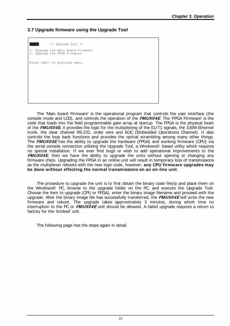
3.7 Upgrade firmware using the Upgrade Tool
The 'Main board Firmware' is the operational program that controls the user interface (the console mode and LCD), and controls the operation of the FMUX04E. The 'FPGA Firmware' is the code that loads into the field programmable gate array at startup. The FPGA is the physical heart of the FMUX04E, it provides the logic for the multiplexing of the E1/T1 signals, the 100M Ethernet trunk, the clear channel RS-232, order wire and EOC (Embedded Operations Channel). It also controls the loop back functions and provides the optical scrambling among many other things. The FMUX04E has the ability to upgrade the hardware (FPGA) and working firmware (CPU) via the serial console connection utilizing the Upgrade Tool, a Windows® based utility which requires no special installation. If we ever find bugs or wish to add operational improvements to the FMUX04E, then we have the ability to upgrade the units without opening or changing any firmware chips. Upgrading the FPGA in an online unit will result in temporary loss of transmissions as the multiplexer reboots with the new logic code, however, any CPU firmware upgrades may be done without effecting the normal transmissions on an on-line unit.
The procedure to upgrade the unit is to first obtain the binary code file(s) and place them on the Windows® PC, browse to the upgrade folder on the PC, and execute the Upgrade Tool. Choose the item to upgrade (CPU or FPGA), enter the binary image filename and proceed with the upgrade. After the binary image file has successfully transferred, the FMUX04E will write the new firmware and reboot. The upgrade takes approximately 3 minutes, during which time no interruption to the PC or FMUX04E unit should be allowed. A failed upgrade requires a return to factory for the ‘bricked’ unit.
The following page has the steps again in detail.
LOCAL << Upgrade Tool >> 1. Upgrade the Main Board Firmware 2. Upgrade the FPGA Firmware Press <ESC> to previous menu.

Chapter 3. Operation
32
Upgrade Procedure
Extract the Upgrade package (Zip file) in a convenient folder on the Windows® PC. The Upgrade Tool has been tested on Window® XP/Vista/Win7. The contents of the extracted folder will look something like this:
{Graphic of folder with Upgrade Tool and binary files.}
Make sure the PC is connected to the FMUX04E using COM1 connection. The Upgrade Tool will only work when connected via COM1 to the FMUX04E. If a laptop is used and the RS-232 is provided via a USB to RS-232 adapter, enter the “Device Manager”, find the “Ports” item. Right click and select “Properties”. In the “USB Serial Port Properties” window select the “Port Setting” tab, then click ‘Advanced’. In the “Advanced Settings” window, change the ‘COM Port Number’ to COM1 and then click ‘OK’. You will probably need to unplug and re-plug the USB device before the new COM port settings take effect.

Chapter 3. Operation
33
{Write the procedure with screen captures here.}
{screen captures}
******************************************************************** Warning : DO NOT power off or terminate the file transfer during the upgrade process or the Flash will crash, leaving the system unstable. ******************************************************************** Upgrading now ..
2. Browse and find the
3. Select CPU or FPGA…
4. Send… 5. Monitor the transfer…

Chapter 3. Operation
34
This completes the overview of the Console mode configuration and status monitoring of the FMUX04E.
The rest of this page was left blank intentionally.
Chapter 4. SNMP
35
Chapter 4. SNMP
4.1 General
The Simple Network Management Protocol (SNMP) is one of many protocols in the Internet Protocol (IP) suite. SNMP is the protocol recommended specifically for the exchange of management information between hosts residing on IP networks. Network management allows you to monitor and control network devices remotely using conventional computer network technology.
The SNMP management functions of the FMUX04E are provided by an internal SNMP agent, which utilizes out-of-band communication over standard 10Base-T or 100Base-TX Ethernet. The SNMP agent is compliant with the SNMPv1 and V2C standard. Future support for SNMP V3 and for IPv6 can be made available through software upgrade.
SNMP communications use the User Datagram Protocol (UDP). UDP is a connectionless transport protocol, part of the TCP/IP suite. The SNMP application uses an asynchronous command/response polling protocol and operates at the OSI Layer 7 (Layer 7 is the Application Layer. Other IP applications that operate at this layer are FTP, Telnet, HTTP, SMTP, etc.). All management traffic is initiated by the SNMP-based network management station. Only the addressed managed entity (agent) answers the polling of the management station (except for trap messages).
4.2 SNMP Operations The SNMP protocol includes five types of operations: getRequest Command for retrieving specific value of an "instance" from the managed node. The managed node responds with a getResponse message. getNextRequest Command for retrieving sequentially specific management information from the managed node. The managed node responds with a getResponse message. getBulkRequest Command for retrieving a block of management information from the managed node. The managed node responds with a getResponse message. getBulkRequest was introduced in SNMPv2c. setRequest Command for manipulating the value of an "instance" within the managed node. The managed node responds with a getResponse message. trap Management message carrying unsolicited information on extraordinary events (that is, events which occurred not in response to a management operation) reported by the managed node.
4.3 The Management Information Base
The management information base (MIB) includes a collection of managed objects. Managed objects are defined as parameters that can be managed, such as specific information on device configuring or on performance statistics values.
The MIB includes the definitions of relevant managed objects (MIB variables) for the specific node. Various MIB's can be defined for various management purposes, types of equipment, etc. The management data itself is a collection of integer, string and MIB address variables that contain all the information necessary to manage the node. A leaf object's definition includes the range of instances (values) and the "access" rights: Read-only Instances of an object can be read, but cannot be set. Read-write Instances of an object can be read or set. Write-only Instances of an object can be set, but cannot be read. Not accessible Instances of an object cannot be read, nor set.

Chapter 4. SNMP
36
4.4 MIB Structure
The MIB has an inverted tree-like structure (root over leaves), with each definition of a managed instance forming one leaf, located at the end of a branch of that tree. Each "leaf" in the MIB is reached by a unique path, therefore by numbering the branching points, starting with the top, each leaf can be uniquely defined by a sequence of numbers. The formal description of the managed objects and the MIB structure is provided in a special standardized format, called Abstract Syntax Notation 1, or ASN.1 (pronounced A-S-N dot one).
Since the general collection of MIB's can also be organized in a similar structure, under the supervision of the Internet Activities Board (IAB), any parameter included in a MIB that is recognized by the IAB is uniquely defined.
To provide the flexibility necessary in a global structure, MIB's are classified in various classes (branches), one of them being the experimental branch, another being the management (mgmt) branch, and yet another the group of private (enterprise-specific) branch. Under the private enterprise-specific branch of MIB's, each enterprise (manufacturer) can be assigned a number, which is its enterprise number. The assigned number designates the top of an enterprise-specific sub-tree of non-standard MIB's.
Enterprise-specific MIB's are published and distributed by their creators, who are responsible for their contents. The MIB supported by the FMUX04E SNMP Agent follows RFC 1213 (MIB-2 standard).
4.5 SNMP Communities
To enable the delimitation of management domains, SNMP uses "communities". Each community is identified by a name, which is an alphanumeric string of up to 255 characters defined by the user. Any SNMP entity (this term includes both managed nodes and management stations) is assigned by its user a community name. In parallel, the user defines for each SNMP entity a list of the communities which are authorized to communicate with it, and the access rights associated with each community (this is the SNMP community name table of the entity). In general, SNMP agents support two types of access rights: Read-only the SNMP agent accepts and processes only SNMP getRequest and getNextRequest commands from management stations which have a read-only community name. Read-write the SNMP agent accepts and processes all the SNMP commands received from a management station with a read-write community name. SNMP agents are usually configured to send traps to management stations having read-write communities.

Chapter 4. SNMP
37
4.6 Configuring the SNMP Agent The agent for the FMUX04E resides in the SNMP option card installed in the FMUX04E. Initial configuration of the agent is accomplished via the RS-232 Control Port of the FMUX04E. Follow the connection, terminal, and operations described in Section 3.1, 3.2, 3.3 and 3.4. SNMP configuration is reached from the main menu using items 7 and 8. 4.6.1 SNMP Agent Configuration
From the main menu, select item number 7, SNMP Agent Configuration. Use this screen to configure the TCP/IP settings for the SNMP agent; the IP address, subnet mask and default gateway settings. [ESC] back to the main menu. Item number 1, IP address is the IP address that the SNMP card will answer to when "pinged", Telnet'd, TFTP'd or when accessed by SNMP. Item number 2, is the subnet mask for the network that the card is attached to. Item number 3, is the default gateway for the network that the card is attached to and is required if the FMUX04E is to be managed from a different subnet.
**************************************** *** CTC UNION TECHNOLOGIES CO.,LTD *** *** FMUX04E Manager Ver:1.00 *** **************************************** [Local ] Version:[1.200-1.000-0.000-0.500] [No SNMP ] <1> Device Status and Configuration <2> Fiber Status and Configuration <3> E1/T1 Status and Configuration <4> LAN Status and Configuration <5> RS232 Status and Configuration <6> Phone Status and Configuration <7> SNMP Agent Configuration <8> Management Configuration <P> Setting Password <T> Switch To Remote Menu [Present] Please select an item.
****************************************
*** CTC UNION TECHNOLOGIES CO.,LTD ***
*** FMUX04E Manager Ver:1.00 ***
****************************************
[Local ] Version:[1.200-1.000-0.000-0.500] [ SNMP ]
<1> IP Address :[ 10. 1. 1. 1 ]
<2> SUB Mask :[ 255. 0. 0. 0 ]
<3> Gateway IP :[ 10. 1. 1.254 ]
<ESC> Go to previous menu. Please select an item

Chapter 4. SNMP
38
4.6.2 Management Configuration
From the main menu, select item number 8, Management Configuration. Manager configuration is required to tell the agent (the SNMP card) who has authority to access the SNMP via "Get" commands (read) or "Set" commands (write) and where to send "trap" messages (unsolicited messages that are usually generated by alarms in the FMUX04E ).
The manager configuration has the ability to setup access for up to four (4) different management workstations. The community strings act like passwords in dealing with the device via SNMP protocol. By changing the community strings (numbered 1 & 2) for read / write ('secret' in this case) and read only ('public') access, and assigning a community string to an access IP, an administrator can control access to the FMUX04E. Explanation
The SNMP agent is the process that runs in the SNMP module and has the ability to control the FMUX04E. The agent requires network configuration, ie. IP address, subnet mask and default gateway settings.
The manager configuration provides the needed information to the agent for the network manager on your network. This information can be assigned for up to four different management workstations. The information set includes the IP address of the management workstation, the access rights (read/write or read only) which are provided by the community string, plus if the agent is to send traps (unsolicited messages) to the management workstation.
The TFTP server is required if doing any software upgrade of the SNMP agent. The two configuration parameters are the IP address of the TFTP server and the path to the upload file.
4.6.3 TFTP and Upgrade Firmware
To upgrade the SNMP firmware, configure a TFTP server on your network. Configuring a TFTP server is beyond the scope of this document. In any upgrade package offered by CTC Union, a detailed upgrade procedure is supplied. Please refer to the document in the upgrade package.
DO NOT INTERRUPT POWER DURING SAVE OPERATION OR THE FLASH MEMORY MAY BECOME CORRUPT.
After the upgrade is complete and the multiplexer has rebooted, go to the 'Display Information' menu and confirm the new firmware version is correct.
****************************************
*** CTC UNION TECHNOLOGIES CO.,LTD ***
*** FMUX04E Manager Ver:1.00 ***
****************************************
[Local ] Version:[1.200-1.000-0.000-0.500] [ SNMP ]
<1> Access IP #1 :[ ]
<2> Access IP #2 :[ ]
<3> Access IP #3 :[ ]
<4> Access IP #4 :[ ]
<5> Community String #1:[ ]
<6> Community String #2:[ ]
<ESC> Go to previous menu. Please select an item

Chapter 4. SNMP
39
4.7 MIB File
A MIB is a "management information base" file that allows network management software to understand how to manage the FMUX04E. Management software could be expensive packages of software such as HP OpenView® and Computer Associates Unicenter®, enterprise level management software such as SNMPc, What’s Up, Orion or inexpensive MIB browsers such as those from MG-Soft. Additionally, Linux and UNIX type operating systems also have SNMP utilities that allow utilizing the MIB file to access the device agent with SNMP protocol that include SNMP walk and trap receiving. The MIB file is just a key that fits our device; you still need the 'car' (management software running on a workstation) in order to drive.
The FMUX04E with SNMP is provided with a MIB (Management Information Base) file. The MIB supported by the FMUX04E SNMP Agent follows RFC 1213 (MIB-2 standard). The formal description of the managed objects and the MIB structure is provided in a special standardized format, called Abstract Syntax Notation 1, or ASN.1 (pronounced A-S-N dot one).
The following graphic shows the MG-SOFT MIB Browser software, after importing and compiling the MIB file, accessing the FMUX04E and doing an 'SNMP Walk' on the local E1 configuration OID. The query results are shown on the right screen.
SNMP 'Walk' displayed on MG-Soft's MIB Browser

Chapter 4. SNMP
40
4.8 Web Based Interface When the FMUX04E is installed with the SNMP option, the unit has the added management features of Telnet, SNMP and HTTP server. The HTTP server allows connection and configuration in a graphical, point and click environment using any standard web browser.
4.8.1 Security Login
To connect to the FMUX04E use the device's IP address as the URL location. For example with our setup unit, enter http://192.168.0.253/ and Enter. A login security prompt will display. The default user name is admin. The password is the terminal password if it has been set, or if no terminal password is set the default is 0000 (4 zeros).
4.8.2 Panel
Panel Our first page is the "Panel" page that shows the condition of both local and remote units. (Note: Remote display is only available if the fiber link is working correctly.) Directly clicking on either graphic will enter the configuration pages for that unit.
4.8.3 Local (Remote) Tab Display
By clicking either the local or remote menu item, the 'Tabbed' page for that unit will be displayed. The top header indicates if this is the Local or Remote unit, the model name and the version. The version fields (4 of them) in order from left to right indicate hardware version (i.e. PCB version), software version, CPLD version and lastly FPGA version. The tabs select between the "Device", "Fiber" (i.e. optical aggregate), "SFP" (including DOM), "E1/T1" (i.e. the tributary channels), "LAN" (i.e. Ethernet trunk and switch) and the "RS232 & Phone" (i.e. clear channel RS-232 and the Ear/Mouth order wire).
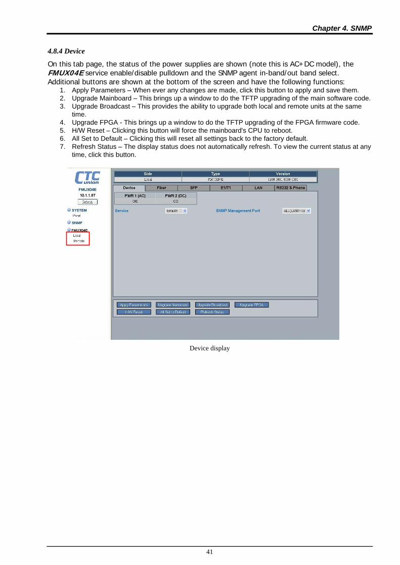
Chapter 4. SNMP
41
4.8.4 Device
On this tab page, the status of the power supplies are shown (note this is AC+DC model), the FMUX04E service enable/disable pulldown and the SNMP agent in-band/out band select. Additional buttons are shown at the bottom of the screen and have the following functions:
1. Apply Parameters – When ever any changes are made, click this button to apply and save them. 2. Upgrade Mainboard – This brings up a window to do the TFTP upgrading of the main software code. 3. Upgrade Broadcast – This provides the ability to upgrade both local and remote units at the same
time. 4. Upgrade FPGA - This brings up a window to do the TFTP upgrading of the FPGA firmware code. 5. H/W Reset – Clicking this button will force the mainboard's CPU to reboot. 6. All Set to Default – Clicking this will reset all settings back to the factory default. 7. Refresh Status – The display status does not automatically refresh. To view the current status at any
time, click this button.
Device display

Chapter 4. SNMP
42
4.8.5 Fiber
The Fiber tab contains the status and settings for the 1+1 fiber aggregate ports. The two optical fiber ports are labeled "OP1" and "OP2". The aggregate link status is shown (requires at least one physical link to be up) and the status of both optical ports. If the SFPs used support optional Digital Diagnostics (Digital Optical Monitor or DOM), then the "D/D" will have "Yes" status. Receive optical signal status is also shown. The FMUX04E also has the ability to show remote power failure (dying gasp) in addition to fiber link down. This can aid in troubleshooting remote problems in which the remote unit was powered off, rather than only observing optical link fault.
Fiber The configurable parameters include:
1. Fiber Working Channel – If two fiber channels are available, the working path can be manually selected.
2. Auto Laser Shutdown – This safety feature will disable the laser output if there is no received signal. 3. Fiber Port Loop Back – this diagnostic utility provides for Local and Remote optical loop back.
4.8.6 SFP
The inventory status of both optical interfaces is displayed on the "SFP" tab.
SFP

Chapter 4. SNMP
43
4.8.7 E1/T1 Configuration
The E1/T1 configuration tab displays the channel status and sets the channel service, line code and termination type for the E1/T1. It also sets the loop back.
E1/T1
4.8.8 LAN
The "LAN" tab has the status display, service settings and Ethernet settings for each of the three LAN ports. The default setting of the LAN ports is with auto-negotiation enabled. Each port is configurable for manual forced mode Ethernet. Please take care when connecting forced mode to another auto device. A duplex mismatch could occur that will cause a severe performance hit.
LAN

Chapter 4. SNMP
44
4.8.9 RS232 & Phone
The "RS232 & Phone" tab has the service settings for the clear channel (up to 230K baud asynchronous RS-232) and the Ear/Mouth order wire. The RS-232 clear channel also has diagnostic loop back functions which can be selected and enabled here. The "Call Out" function is an option to manually call the operator on the remote FMUX04E.
RS232 & Phone
4.8.10 SNMP Manager and Trap
Clicking the left menu "SNMP" item will bring up the SNMP and Trap configuration page. In order for a manager to manage this device and/or to receive traps, both the manager's IP address and the desired 'community string' must be input on this page. The FMUX04E has the ability to set four entries for managers and trap destinations.
SNMP

Chapter 4. SNMP
45
4.8.11 System Configuration
Configures the SNMP agent's TCP/IP settings and for TFTP upgrade. Keyin all parameters and then click 'Apply Parameters' button. Note that changing the IP address requires the SNMP agent to be rebooted. If you change the IP address to a different broadcast domain, your browser will not be able to reconnect with this unit. So, be careful, especially if doing remote management. If TCP/IP connection is lost, only local serial console can be used to reset the IP address. The other parameters set here are for doing upgrading. For example, the TFTP server's IP address and image filenames are set here as well as the 'System Name' or 'Hostname'. Rememebr to click 'Apply Parameters' to save any changed settings.
System This completes the review of the Web based management features of the FMUX04E.

Chapter 4. SNMP
46
This page was left blank intentionally.

Appendix A. Miscellaneous
47
Appendix A. Miscellaneous
A.1 Console port pin assignment The console port on the FMUX04E serves two purposes; it provides the RS-232 communication interface for terminal configuration and also contains one set of relay contacts for alarm.
Pin Signal Description Direction Remark 1 2 TD Transmit Data IN Towards FMUX04E 3 RD Receive Data OUT From FMUX04E 4 NO Relay Normally open Closed if power fail 5 SG Signal Ground 6 COM Relay Common 7 CTS Clear To Send OUT From FMUX04E 8 RTS Request To Send IN Towards FMUX04E 9 NC Relay Normally closed Closed if no alarm
A.2 Alarm Relay Connection Detail The following are examples of wiring audio or visual alarms to the console/alarm relay DB9F connector. Contact Ratings: 1A @ 30VDC 0.5A @ 125VAC 0.25A @ 250VAC 500VAC Max.
A.3 RS-232 Clear Channel Detail The FMUX04E comes with and RJ-45 to DB9F adapter cable to adapt the RS-232 clear channel’s RJ-45 to standard RS-232 on DB9 Female. The adapter cable is 20cm in length and provides a DCE presentation of RS-232 three wire with transmit, receive and signal ground only.
Pin Signal Description Pin on DB9F 1 SG Signal Ground 5 – Signal Gnd 2 RD RD (output) 2 – RD (out) 3 TD TD (input) 3 – TD (in) 4 NC No connection NC 5 NC No connection NC 6 NC No connection NC 7 NC No connection NC 8 NC No connection NC

Appendix A. Miscellaneous
48
A.4 Console cable pin assignment CAB-DB9DB9F-232-3
A.5 LAN pin assignment The LAN 1~3 connectors are standard MDIX RJ-45 Ethernet connectors located on the rear panel of the FMUX04E. A medium dependent interface (MDI) port or an uplink port is an Ethernet port connection typically used on a Network Interface Card (NIC) or Integrated NIC port on a PC. Since inputs on a NIC must go to outputs on the switch these switch devices have their inputs and outputs (transmit and receive signals) reversed in a configuration known as MDIX or MDI-X. The switch used in the FMUX04E supports Auto-MDIX which allows connection to other switches without an Ethernet crossover cable, but with a straight-through cable. Auto-MDIX is designed to detect if the connection is backwards and automatically chooses MDI or MDIX to properly match the connection.
Pin Signal Description 1 Rx Receive (+) 2 Rx Receive (-) 3 Tx Transmit (+) 4 NC No connection 5 NC No connection 6 Tx Transmit (-) 7 NC No connection 8 NC No connection
A.6 E1/T1 RJ-45 pin assignment The pin assignment of the E1/T1 on RJ-45 follows USOC RJ-48C standard for network termination. When connecting to other network terminating device, be sure to use a cross-over cable.
Pin Signal Description 1 RRing Receive (-) 2 RTip Receive (+) 3 NC No connection 4 TRing Transmit (-) 5 TTip Transmit (+) 6 NC No connection 7 Shield Chassis connection 8 Shield Chassis connection
1 2 3 4 5 6 7 8 9
1 2 3 4 5 6 7 8 9
1 2 3 4 5 6 7 8 9
DB9F
Terminal
DB9M DB9M
FMUX04E Alarm
NO
Common
NC
20cm 20cm
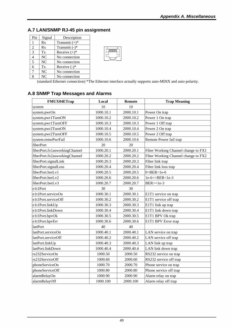
Appendix A. Miscellaneous
49
A.7 LAN/SNMP RJ-45 pin assignment Pin Signal Description 1 Rx Transmit (+)* 2 Rx Transmit (-)* 3 Tx Receive (+)* 4 NC No connection 5 NC No connection 6 Tx Receive (-)* 7 NC No connection 8 NC No connection
(standard Ethernet connection) *The Ethernet interface actually supports auto-MDIX and auto polarity.
A.8 SNMP Trap Messages and Alarms FMUX04ETrap Local Remote Trap Meaning
system 10 10 system.pwrOn 1000.10.1 2000.10.1 Power On trap system.pwr1TurnON 1000.10.2 2000.10.2 Power 1 On trap system.pwr1TurnOFF 1000.10.3 2000.10.3 Power 1 Off trap system.pwr2TurnON 1000.10.4 2000.10.4 Power 2 On trap system.pwr2TurnOFF 1000.10.5 2000.10.5 Power 2 Off trap system.remoPwrFail 1000.10.6 2000.10.6 Remote Power fail trap fiberPort 20 20 fiberPort.fx1asworkingChannel 1000.20.1 2000.20.1 Fiber Working Channel change to FX1 fiberPort.fx2asworkingChannel 1000.20.2 2000.20.2 Fiber Working Channel change to FX2 fiberPort.signalLink 1000.20.3 2000.20.3 Fiber link trap fiberPort.signalLoss 1000.20.4 2000.20.4 Fiber link loss trap fiberPort.berLv1 1000.20.5 2000.20.5 0<BER<1e-6 fiberPort.berLv2 1000.20.6 2000.20.6 1e-6<=BER<1e-3 fiberPort.berLv3 1000.20.7 2000.20.7 BER>=1e-3 e1t1Port 30 30 e1t1Port.serviceOn 1000.30.1 2000.30.1 E1T1 service on trap e1t1Port.serviceOff 1000.30.2 2000.30.2 E1T1 service off trap e1t1Port.linkUp 1000.30.3 2000.30.3 E1T1 link up trap e1t1Port.linkDown 1000.30.4 2000.30.4 E1T1 link down trap e1t1Port.bpvOk 1000.30.5 2000.30.5 E1T1 BPV Ok trap e1t1Port.bpvErr 1000.30.6 2000.30.6 E1T1 BPV Error trap lanPort 40 40 lanPort.serviceOn 1000.40.1 2000.40.1 LAN service on trap lanPort.serviceOff 1000.40.2 2000.40.2 LAN service off trap lanPort.linkUp 1000.40.3 2000.40.3 LAN link up trap lanPort.linkDown 1000.40.4 2000.40.4 LAN link down trap rs232ServiceOn 1000.50 2000.50 RS232 service on trap rs232ServiceOff 1000.60 2000.60 RS232 service off trap phoneServiceOn 1000.70 2000.70 Phone service on trap phoneServiceOff 1000.80 2000.80 Phone service off trap alarmRelayOn 1000.90 2000.90 Alarm relay on trap alarmRelayOff 1000.100 2000.100 Alarm relay off trap

Appendix A. Miscellaneous
50
A.9 SNMP Object Details Path=iso.org.dod.private.enterprise.ctc.fmux04e.localModel (.1.3.6.1.4.1.4756.47.1)
MIB OID Description
localModel 1 Model: 1:FRM220-FMUX04E.
remoteModel 2 Model: 1:empty 2:RM220-FOM04 3:RM220-FMUX04E
localCards 40 Local Unit Parameters
cardHWVerLocal 40.1 Local hardware version x.xxx
cardFWVerLocal 40.2 Local firmware version x.xxx
cardCPLDVerLocal 40.3 Local device card CPLD version x.xxx
cardFPGAVerLocal 40.4 Local device card FPGA version x.xxx
devPower1stsLocal 40.5 Power1 status: 1:None 2:Fail 3:Normal
devPower2stsLocal 40.6 Power2 status: 1:None 2:Fail 3:Normal
devServiceLocal 40.7 Local device status: 1:Off 2:On
fiberlinkLocal 40.8 Local device card fiber link status: 1:Link down 2:Link up
fiberRemoPWRLocal 40.9 Local device card fiber port remote power status: 1:Abnormal 2:OK
fiberALSLocal 40.10 Local device card fiber port Auto Laser Shutdown 1:Disable 2:Enable
op1LinkLocal 40.11 Local device card fiber port 1 status: 1:Link down 2:Link up
op2LinkLocal 40.12 Local device card fiber port 2 status: 1:Link down 2:Link up
op1SFPLocal 40.13 Local device card fiber port 1 status: 1:No 2:Yes
op1ddLocal 40.14 Local device card fiber Digital Diagnostic function: 1:No 2:Yes

Appendix A. Miscellaneous
51
op2SFPLocal 40.15 Local device card fiber port
2 status: 1:No 2:Yes
op2ddLocal 40.16 Local device card fiber Digital Diagnostic function: 1:No 2:Yes
fiberWorkingChannelLocal 40.17 Local device card fiber port status: 1:OP1 2:OP2
fiberLoopBackLocal 40.18 Local device card loop back test mode: 1:Disable 2:LLB 3:RLB
op1ddVendorLocal 40.19 Local device card fiber D/D information: Vendor name
op1ddPartNoLocal 40.20 Local device card fiber port 1 D/D information: Vendor part number
op1ddTypeLocal 40.21 Local device card fiber port 1 D/D information: Fiber Type: 1:Unknown 2:Multi 3:Single
op1ddTxWaveLenLocal 40.22 Local device card fiber port 1 D/D information: Tx Wave Length
op1ddRxWaveLenLocal 40.23 Local device card fiber port 1 D/D information: Rx Wave Length
op1ddLinkLenLocal 40.24 Local device card fiber port 1 D/D information: Link Length
op1ddLenUnitLocal 40.25 Local device card fiber port 1 D/D information: Length Unit: 1:kilometer 2:meter
op1ddTxPWRLocal 40.26 Local device card fiber port 1 D/D information: Tx Power
op1ddRxPWRLocal 40.27 Local device card fiber port 1 D/D information: Rx Power
op1ddRxSensLocal 40.28 Local device card fiber port 1 D/D information: Rx Sensitivity
op1ddTempLocal 40.29 Local device card fiber port 1 D/D information: Temperature in degree C

Appendix A. Miscellaneous
52
op2ddVendorLocal 40.30 Local device card fiber D/D
information: Vendor name op2ddPartNoLocal 40.31 Local device card fiber port
2 D/D information: Vendor part number
op2ddTypeLocal 40.32 Local device card fiber port 2 D/D information: Fiber Type: 1:Unknown 2:Multi 3:Single
op2ddTxWaveLenLocal 40.33 Local device card fiber port 2 D/D information: Tx Wave Length
op2ddRxWaveLenLocal 40.34 Local device card fiber port 2 D/D information: Rx Wave Length
op2ddLinkLenLocal 40.35 Local device card fiber port 2 D/D information: Link Length
op2ddLenUnitLocal 40.36 Local device card fiber port 2 D/D information: Length Unit: 1:kilometer 2:meter
op2ddTxPWRLocal 40.37 Local device card fiber port 2 D/D information: Tx Power
op2ddRxPWRLocal 40.38 Local device card fiber port 2 D/D information: Rx Power
op2ddRxSensLocal 40.39 Local device card fiber port 2 D/D information: Rx Sensitivity
op2ddTempLocal 40.40 Local device card fiber port 2 D/D information: Temperature in degree C
e1T1TermTypeLocal 40.41 Local device E1T1 termination type: 1:E1/75/BNC 2:E1/120/RJ45 3:T1/100/RJ45
e1T1Ch1L 40.42 Local E1/T1 Ch1
e1T1Ch1linkLocal 40.42.1 Local device E1T1 status: 1:Link down 2:Link up
e1T1Ch1serviceLocal 40.42.2 Local device E1T1 status: 1:Off 2:On
e1T1Ch1bvpErrorLocal 40.42.3 Display BPV: 1:Off 2:On
e1T1Ch1lineCodeLocal 40.42.4 Set the line code: 1:HDB3/B8ZS 2AMI

Appendix A. Miscellaneous
53
e1T1Ch1loopBackLocal 40.42.5 Local device E1T1 local
loop back function & select setting: 1:Disable 2:LLB 3:RLB
e1T1Ch2L 40.43 Local E1/T1 Ch2
e1T1Ch2linkLocal 40.43.1 Local device E1T1 status: 1:Link down 2:Link up
e1T1Ch2serviceLocal 40.43.2 Local device E1T1 status: 1:Off 2:On
e1T1Ch2bvpErrorLocal 40.43.3 Display BPV: 1:Off 2:On
e1T1Ch2lineCodeLocal 40.43.4 Set the line code: 1:HDB3/8ZS 2AMI
e1T1Ch2loopBackLocal 40.43.5 Local device E1T1 local loop back function & select setting: 1:Disable 2:LLB 3:RLB
e1T1Ch3L 40.44 LocalE1/T1 Ch3
e1T1Ch3linkLocal 40.44.1 Local device E1T1 status: 1:Link down 2:Link up
e1T1Ch3serviceLocal 40.44.2 Local device E1T1 status: 1:Off 2:On
e1T1Ch3bvpErrorLocal 40.44.3 Display BPV: 1:Off 2:On
e1T1Ch3lineCodeLocal 40.44.4 Set the line code: 1:HDB3/8ZS 2AMI
e1T1Ch3loopBackLocal 40.44.5 Local device E1T1 local loop back function & select setting: 1:Disable 2:LLB 3:RLB
e1T1Ch4L 40.45 Local E1/T1 Ch4
e1T1Ch4linkLocal 40.45.1 Local device E1T1 status: 1:Link down 2:Link up
e1T1Ch4serviceLocal 40.45.2 Local device E1T1 status: 1:Off 2:On
e1T1Ch4bvpErrorLocal 40.45.3 Display BPV: 1:Off 2:On
e1T1Ch4lineCodeLocal 40.45.4 Set the line code: 1:HDB3/8ZS 2AMI

Appendix A. Miscellaneous
54
e1T1Ch4loopBackLocal 40.45.5 Local device E1T1 local
loop back function & select setting: 1:Disable 2:LLB 3:RLB
portVLANLocal 40.46 Local device port based VLAN mode: 1:Disable 2:Enable
utp1L 40.47 Local LAN 1
utp1serviceLocal 40.47.1 Local device UTP port 1 status: 1:Off 2:On
utp1linkLocal 40.47.2 Local device UTP port 1 link status: 1:Link down 2:Link up
utp1rxActiveLocal 40.47.3 Local device UTP port 1 Rx active status: 1:Off 2:On
utp1negoLocal 40.47.4 Local device UTP port 1 negotiation status: 1:Manual 2:Auto
utp1speedLocal 40.47.5 Local device UTP port 1 speed status: 1:10Mb 2:100Mb
utp1duplexLocal 40.47.6 Local device UTP port 1 duplex status: 1:Half duplex mode 2:Full duplex mode
utp1flowCtrlLocal 40.47.7 Local device UTP port 1 flow control status: 1:Off 2:On
utp2L 40.48 Local LAN 2
utp2serviceLocal 40.48.1 Local device UTP port 2 status: 1:Off 2:On
utp2linkLocal 40.48.2 Local device UTP port 2 link status: 1:Link down 2:Link up
utp2rxActiveLocal 40.48.3 Local device UTP port 2 Rx active status: 1:Off 2:On
utp2negoLocal 40.48.4 Local device UTP port 2 negotiation status: 1:Manual 2:Auto
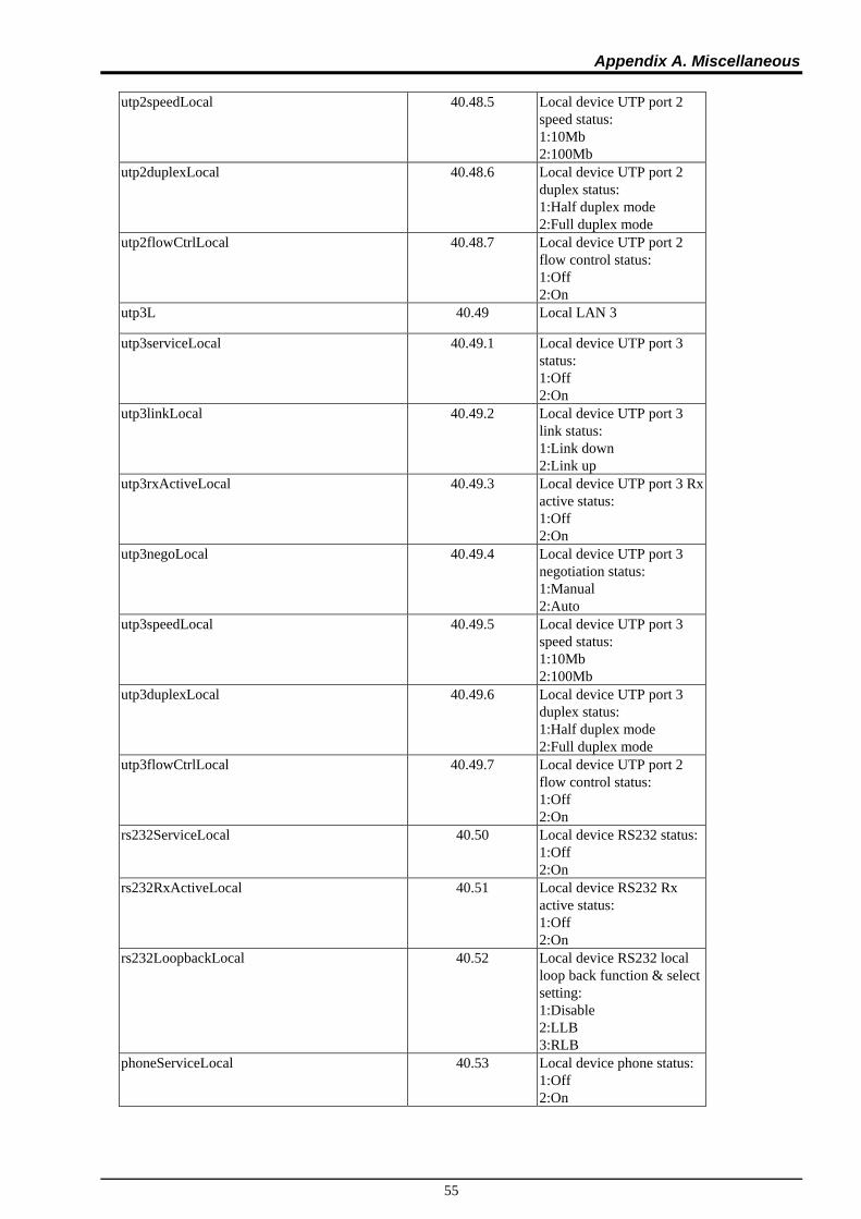
Appendix A. Miscellaneous
55
utp2speedLocal 40.48.5 Local device UTP port 2
speed status: 1:10Mb 2:100Mb
utp2duplexLocal 40.48.6 Local device UTP port 2 duplex status: 1:Half duplex mode 2:Full duplex mode
utp2flowCtrlLocal 40.48.7 Local device UTP port 2 flow control status: 1:Off 2:On
utp3L 40.49 Local LAN 3
utp3serviceLocal 40.49.1 Local device UTP port 3 status: 1:Off 2:On
utp3linkLocal 40.49.2 Local device UTP port 3 link status: 1:Link down 2:Link up
utp3rxActiveLocal 40.49.3 Local device UTP port 3 Rx active status: 1:Off 2:On
utp3negoLocal 40.49.4 Local device UTP port 3 negotiation status: 1:Manual 2:Auto
utp3speedLocal 40.49.5 Local device UTP port 3 speed status: 1:10Mb 2:100Mb
utp3duplexLocal 40.49.6 Local device UTP port 3 duplex status: 1:Half duplex mode 2:Full duplex mode
utp3flowCtrlLocal 40.49.7 Local device UTP port 2 flow control status: 1:Off 2:On
rs232ServiceLocal 40.50 Local device RS232 status: 1:Off 2:On
rs232RxActiveLocal 40.51 Local device RS232 Rx active status: 1:Off 2:On
rs232LoopbackLocal 40.52 Local device RS232 local loop back function & select setting: 1:Disable 2:LLB 3:RLB
phoneServiceLocal 40.53 Local device phone status: 1:Off 2:On

Appendix A. Miscellaneous
56
remoteCards 50 Remote Unit Parameters
cardHWVerRemote 50.1 Remote hardware version x.xxx
cardFWVerRemote 50.2 Remote firmware version x.xxx
cardCPLDVerRemote 50.3 Remote device card CPLD version x.xxx
cardFPGAVerRemote 50.4 Remote device card FPGA version x.xxx
devPower1stsRemote 50.5 Power1 status: 1:None 2:Fail 3:Normal
devPower2stsRemote 50.6 Power2 status: 1:None 2:Fail 3:Normal
devBerRemote 50.7 Get the bit err rate
devServiceRemote 50.8 Remote device status: 1:Off 2:On
fiberlinkRemote 50.9 Remote device card fiber link status: 1:Link down 2:Link up
fiberRemoPWRRemote 50.10 Remote device card fiber port remote power status: 1:Abnormal 2:OK
op1LinkRemote 50.11 Remote device card fiber port 1 status: 1:Link down 2:Link up
op2LinkRemote 50.12 Remote device card fiber port 2 status: 1:Link down 2:Link up
op1SFPRemote 50.13 Remote device card fiber port 1 status: 1:No 2:Yes
op1ddRemote 50.14 Remote device card fiber Digital Diagnostic function: 1:No 2:Yes
op2SFPRemote 50.15 Remote device card fiber port 2 status: 1:No 2:Yes
op2ddRemote 50.16 Remote device card fiber Digital Diagnostic function: 1:No 2:Yes
fiberWorkingChannelRemote 50.17 Remote device card fiber port status: 1:FX1 2:FX2

Appendix A. Miscellaneous
57
fiberLoopBackRemote 50.18 Remote device card loop
back test mode: 1:Disable 2:LLB 3:RLB
op1ddVendorRemote 50.19 Remote device card fiber D/D information: Vendor name
op1ddPartNoRemote 50.20 Remote device card fiber port 1 D/D information: Vendor part number
op1ddTypeRemote 50.21 Remote device card fiber port 1 D/D information: Fiber Type: 1:Unknown 2:Multi 3:Single
op1ddTxWaveLenRemote 50.22 Remote device card fiber port 1 D/D information: Tx Wave Length
op1ddRxWaveLenRemote 50.23 Remote device card fiber port 1 D/D information: Rx Wave Length
op1ddLinkLenRemote 50.24 Remote device card fiber port 1 D/D information: Link Length
op1ddLenUnitRemote 50.25 Remote device card fiber port 1 D/D information: Length Unit 1:kilometer 2:meter
op1ddTxPWRRemote 50.26 Remote device card fiber port 1 D/D information: Tx Power
op1ddRxPWRRemote 50.27 Remote device card fiber port 1 D/D information: Rx Power
op1ddRxSensRemote 50.28 Remote device card fiber port 1 D/D information: Rx Sensitivity
op1ddTempRemote 50.29 Remote device card fiber port 1 D/D information: Temperature in degree C
op2ddVendorRemote 50.30 Remote device card fiber D/D information: Vendor name
op2ddPartNoRemote 50.31 Remote device card fiber port 2 D/D information: Vendor part number
op2ddTypeRemote 50.32 Remote device card fiber port 2 D/D information: Fiber Type: 1:Unknown 2:Multi 3:Single
op2ddTxWaveLenRemote 50.33 Remote device card fiber port 2 D/D information: Tx Wave Length

Appendix A. Miscellaneous
58
op2ddRxWaveLenRemote 50.34 Remote device card fiber
port 2 D/D information: Rx Wave Length
op2ddLinkLenRemote 50.35 Remote device card fiber port 2 D/D information: Link Length
op2ddLenUnitRemote 50.36 Remote device card fiber port 2 D/D information: Length Unit: 1:kilometer 2:meter
op2ddTxPWRRemote 50.37 Remote device card fiber port 2 D/D information: Tx Power
op2ddRxPWRRemote 50.38 Remote device card fiber port 2 D/D information: Rx Power
op2ddRxSensRemote 50.39 Remote device card fiber port 2 D/D information: Rx Sensitivity
op2ddTempRemote 50.40 Remote device card fiber port 2 D/D information: Temperature in degree C
e1T1TermTypeRemote 50.41 Remote device E1T1 termination type: 1:E1/75/BNC 2:E1/120/RJ45 3:T1/100/RJ45
e1T1Ch1R 50.42 Remote E1/T1 Ch1
e1T1Ch1linkRemote 50.42.1 Remote device E1T1 status: 1:Link down 2:Link up
e1T1Ch1serviceRemote 50.42.2 Remote device E1T1 status: 1:Off 2:On
e1T1Ch1bvpErrorRemote 50.42.3 Display BPV: 1:Off 2:On
e1T1Ch1lineCodeRemote 50.42.4 Set the line code: 1:HDB3/8ZS 2AMI
e1T1Ch1loopBackRemote 50.42.5 Remote device E1T1 local loop back function & select setting: 1:Disable 2:LLB 3:RLB
e1T1Ch2 50.43 Remote E1/T1 Ch2
e1T1Ch2linkRemote 50.43.1 Remote device E1T1 status: 1:Link down 2:Link up
e1T1Ch2serviceRemote 50.43.2 Remote device E1T1 status: 1:Off 2:On
e1T1Ch2bvpErrorRemote 50.43.3 Display BPV: 1:Off 2:On

Appendix A. Miscellaneous
59
e1T1Ch2lineCodeRemote 50.43.4 Set the line code:
1:HDB3/8ZS 2AMI
e1T1Ch2loopBackRemote 50.43.5 Remote device E1T1 local loop back function & select setting: 1:Disable 2:LLB 3:RLB
e1T1Ch3R 50.44 Remote E1/T1 Ch3
e1T1Ch3linkRemote 50.44.1 Remote device E1T1 status: 1:Link down 2:Link up
e1T1Ch3serviceRemote 50.44.2 Remote device E1T1 status: 1:Off 2:On
e1T1Ch3bvpErrorRemote 50.44.3 Display BPV: 1:Off 2:On
e1T1Ch3lineCodeRemote 50.44.4 Set the line code: 1:HDB3/8ZS 2AMI
e1T1Ch.loopBackRemote 50.44.5 Remote device E1T1 local loop back function & select setting: 1:Disable 2:LLB 3:RLB
e1T1Ch4R 50.45 Remote E1/T1 Ch4
e1T1Ch4linkRemote 50.45.1 Remote device E1T1 status: 1:Link down 2:Link up
e1T1Ch4serviceRemote 50.45.2 Remote device E1T1 status: 1:Off 2:On
e1T1Ch4bvpErrorRemote 50.45.3 Display BPV: 1:Off 2:On
e1T1Ch4lineCodeRemote 50.45.4 Set the line code: 1:HDB3/8ZS 2AMI
e1T1Ch4loopBackRemote 50.45.5 Remote device E1T1 local loop back function & select setting: 1:Disable 2:LLB 3:RLB
portVLANRemote 50.46 Remote device port based VLAN mode: 1:Disable 2:Enable
utp1R 50.47 Remote LAN 1
utp1serviceRemote 50.47.1 Remote device UTP port 1 status: 1:Off 2:On

Appendix A. Miscellaneous
60
utp1linkRemote 50.47.2 Remote device UTP port 1
link status: 1:Off 2:On
utp1rxActiveRemote 50.47.3 Remote device UTP port 1 Rx active status: 1:Off 2:On
utp1negoRemote 50.47.4 Remote device UTP port 1 negotiation status: 1:Manual 2:Auto
utp1speedRemote 50.47.5 Remote device UTP port 1 speed status: 1:10Mb 2:100Mb
utp1duplexRemote 50.47.6 Remote device UTP port 1 duplex status: 1:Half duplex mode 2:Full duplex mode
utp1flowCtrlRemote 50.47.7 Remote device UTP port 1 flow control status: 1:Off 2:On
utp2R 50.48 Remote LAN 2
utp2serviceRemote 50.48.1 Remote device UTP port 2 status: 1:Off 2:On
utp2linkRemote 50.48.2 Remote device UTP port 2 link status: 1:Off 2:On
utp2rxActiveRemote 50.48.3 Remote device UTP port 2 Rx active status: 1:Off 2:On
utp2negoRemote 50.48.4 Remote device UTP port 2 negotiation status: 1:Manual 2:Auto
utp2speedRemote 50.48.5 Remote device UTP port 2 speed status: 1:10Mb 2:100Mb
utp2duplexRemote 50.48.6 Remote device UTP port 2 duplex status: 1:Half duplex mode 2:Full duplex mode
utp2flowCtrlRemote 50.48.7 Remote device UTP port 2 flow control status: 1:Off 2:On
utp3R 50.49 Remote LAN 3
utp3serviceRemote 50.49.1 Remote device UTP port 3 status: 1:Off 2:On
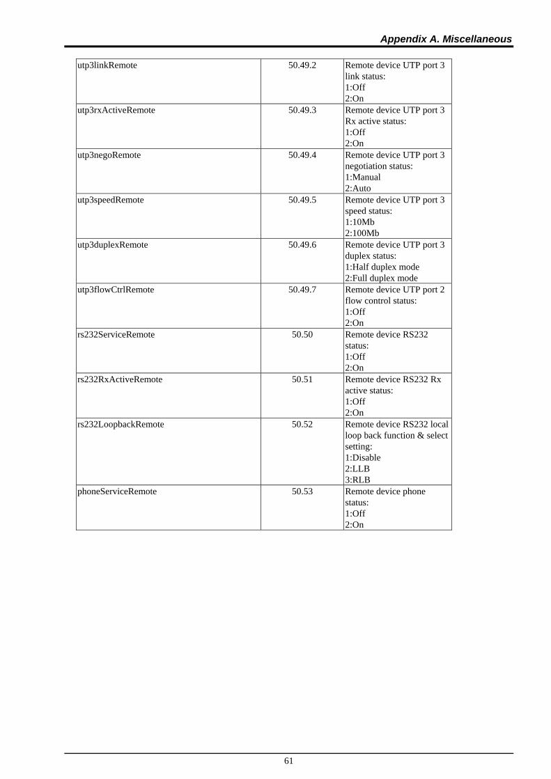
Appendix A. Miscellaneous
61
utp3linkRemote 50.49.2 Remote device UTP port 3
link status: 1:Off 2:On
utp3rxActiveRemote 50.49.3 Remote device UTP port 3 Rx active status: 1:Off 2:On
utp3negoRemote 50.49.4 Remote device UTP port 3 negotiation status: 1:Manual 2:Auto
utp3speedRemote 50.49.5 Remote device UTP port 3 speed status: 1:10Mb 2:100Mb
utp3duplexRemote 50.49.6 Remote device UTP port 3 duplex status: 1:Half duplex mode 2:Full duplex mode
utp3flowCtrlRemote 50.49.7 Remote device UTP port 2 flow control status: 1:Off 2:On
rs232ServiceRemote 50.50 Remote device RS232 status: 1:Off 2:On
rs232RxActiveRemote 50.51 Remote device RS232 Rx active status: 1:Off 2:On
rs232LoopbackRemote 50.52 Remote device RS232 local loop back function & select setting: 1:Disable 2:LLB 3:RLB
phoneServiceRemote 50.53 Remote device phone status: 1:Off 2:On

Appendix A. Miscellaneous
62