FMPRV41 - Forbes Marshall · 2 Adjustment lock nut SS Type 304 3 ... DN 40 FMPRV41 having a 0.2-17...
4
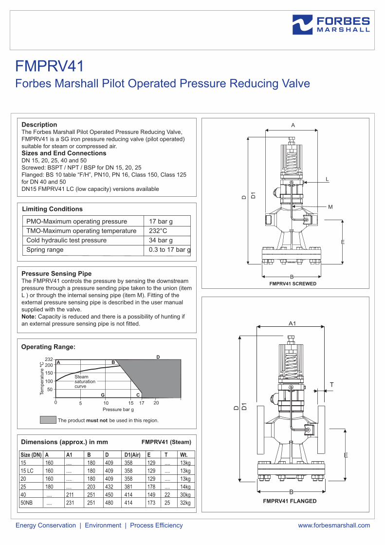
Description The Forbes Marshall Pilot Operated Pressure Reducing Valve, FMPRV41 is a SG iron pressure reducing valve (pilot operated) suitable for steam or compressed air. Sizes and End Connections DN 15, 20, 25, 40 and 50 Screwed: BSPT / NPT / BSP for DN 15, 20, 25 Flanged: BS 10 table “F/H”, PN10, PN 16, Class 150, Class 125 for DN 40 and 50 DN15 FMPRV41 LC (low capacity) versions available Limiting Conditions PMO-Maximum operating pressure 17 bar g TMO-Maximum operating temperature 232°C Cold hydraulic test pressure 34 bar g Spring range 0.3 to 17 bar g Pressure Sensing Pipe The FMPRV41 controls the pressure by sensing the downstream pressure through a pressure sending pipe taken to the union (item L ) or through the internal sensing pipe (item M). Fitting of the external pressure sensing pipe is described in the user manual supplied with the valve. Note: Capacity is reduced and there is a possibility of hunting if an external pressure sensing pipe is not fitted. Operating Range: The product must not be used in this region. Pressure bar g Temperature °C A E Steam saturation curve C F B D G 0 5 15 20 10 17 100 150 50 200 232 www.forbesmarshall.com Energy Conservation | Environment | Process Efficiency Dimensions (approx.) in mm FMPRV41 (Steam) FMPRV41 SCREWED D L M E A B FMPRV41 FLANGED A1 D B T E D1 D1 Size (DN) A A1 B D D1(Air) E T Wt. 15 160 .... 180 409 358 129 .... 13kg 15 LC 160 .... 180 409 358 129 .... 13kg 20 160 .... 180 409 358 129 .... 13kg 25 180 .... 203 432 381 178 .... 14kg 40 .... 211 251 450 414 149 22 30kg 50NB .... 231 251 480 414 173 25 32kg Forbes Marshall Pilot Operated Pressure Reducing Valve FMPRV41
-
Upload
truongdieu -
Category
Documents
-
view
278 -
download
2
Transcript of FMPRV41 - Forbes Marshall · 2 Adjustment lock nut SS Type 304 3 ... DN 40 FMPRV41 having a 0.2-17...
DescriptionThe Forbes Marshall Pilot Operated Pressure Reducing Valve, FMPRV41 is a SG iron pressure reducing valve (pilot operated) suitable for steam or compressed air.Sizes and End ConnectionsDN 15, 20, 25, 40 and 50 Screwed: BSPT / NPT / BSP for DN 15, 20, 25Flanged: BS 10 table “F/H”, PN10, PN 16, Class 150, Class 125 for DN 40 and 50DN15 FMPRV41 LC (low capacity) versions available
Limiting Conditions
PMO-Maximum operating pressure 17 bar g
TMO-Maximum operating temperature 232°C
Cold hydraulic test pressure 34 bar g
Spring range 0.3 to 17 bar g
Pressure Sensing PipeThe FMPRV41 controls the pressure by sensing the downstream pressure through a pressure sending pipe taken to the union (item L ) or through the internal sensing pipe (item M). Fitting of the external pressure sensing pipe is described in the user manual supplied with the valve.Note: Capacity is reduced and there is a possibility of hunting if an external pressure sensing pipe is not fitted.
Operating Range:
The product must not be used in this region.
Pressure bar g
Tem
pe
ratu
re °
C A
E
Steamsaturationcurve
C
F
BD
G
0 5 15 2010 17
100
150
50
200232
www.forbesmarshall.comEnergy Conservation | Environment | Process Efficiency
Dimensions (approx.) in mm FMPRV41 (Steam)
FMPRV41 SCREWED
D
L
M
E
A
B
FMPRV41 FLANGED
A1
D
B
T
E
D1
D1
Size (DN) A A1 B D D1(Air) E T Wt.
15 160 .... 180 409 358 129 .... 13kg
15 LC 160 .... 180 409 358 129 .... 13kg
20 160 .... 180 409 358 129 .... 13kg
25 180 .... 203 432 381 178 .... 14kg
40 .... 211 251 450 414 149 22 30kg
50NB .... 231 251 480 414 173 25 32kg
Forbes Marshall Pilot Operated Pressure Reducing Valve
FMPRV41
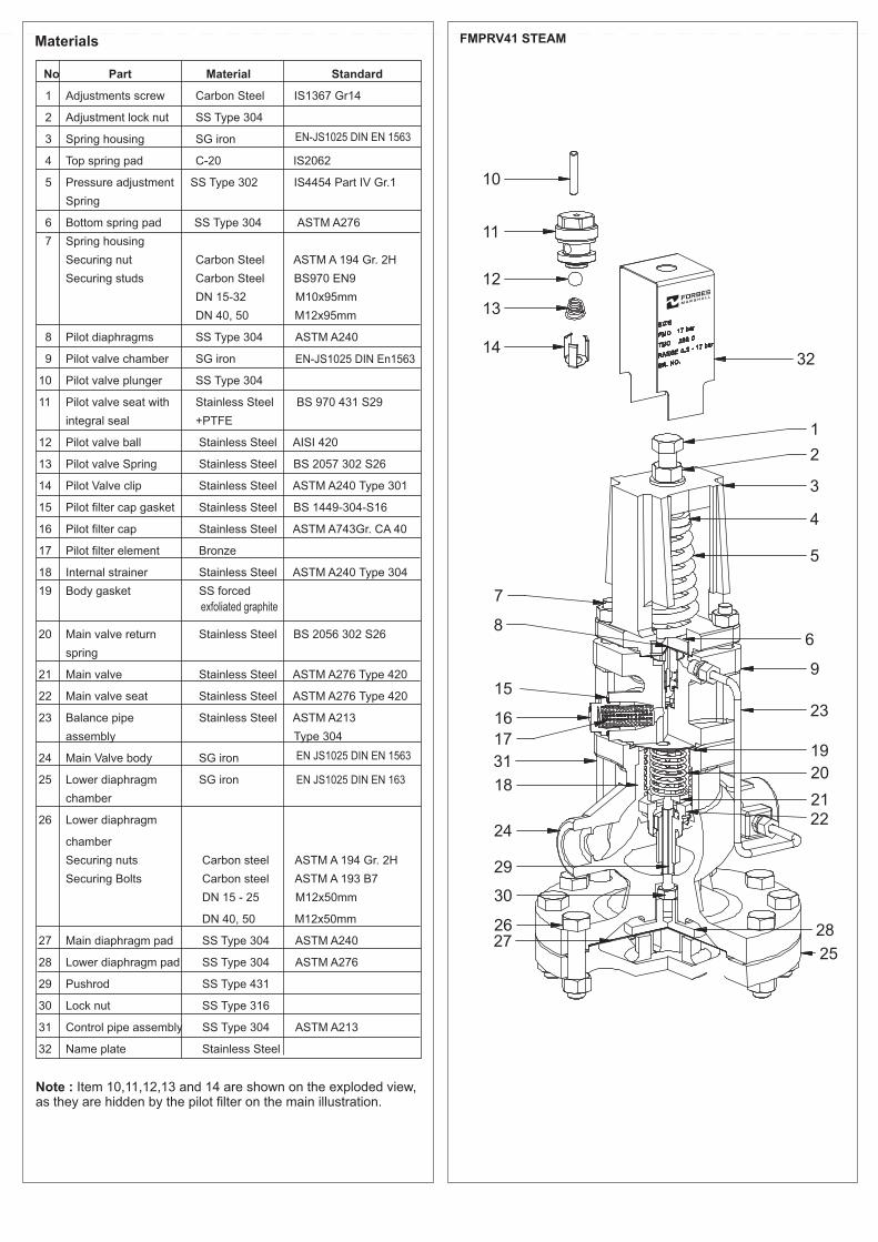
Materials FMPRV41 STEAM
Note : Item 10,11,12,13 and 14 are shown on the exploded view, as they are hidden by the pilot filter on the main illustration.
No Part Material Standard
1 Adjustments screw Carbon Steel IS1367 Gr14
2 Adjustment lock nut SS Type 304
3 Spring housing SG iron
4 Top spring pad C-20 IS2062
5 Pressure adjustment SS Type 302 IS4454 Part IV Gr.1
Spring
6 Bottom spring pad SS Type 304 ASTM A276
7 Spring housing
Securing nut Carbon Steel ASTM A 194 Gr. 2H
Securing studs Carbon Steel BS970 EN9
DN 15-32 M10x95mm
DN 40, 50 M12x95mm
8 Pilot diaphragms SS Type 304 ASTM A240
9 Pilot valve chamber SG iron
10 Pilot valve plunger SS Type 304
11 Pilot valve seat with Stainless Steel BS 970 431 S29
integral seal +PTFE
12 Pilot valve ball Stainless Steel AISI 420
13 Pilot valve Spring Stainless Steel BS 2057 302 S26
14 Pilot Valve clip Stainless Steel ASTM A240 Type 301
15 Pilot filter cap gasket Stainless Steel BS 1449-304-S16
16 Pilot filter cap Stainless Steel ASTM A743 Gr. CA 40
17 Pilot filter element Bronze
18 Internal strainer Stainless Steel ASTM A240 Type 304
19 Body gasket SS forced
20 Main valve return Stainless Steel BS 2056 302 S26
spring
21 Main valve Stainless Steel ASTM A276 Type 420
22 Main valve seat Stainless Steel ASTM A276 Type 420
23 Balance pipe Stainless Steel ASTM A213
assembly Type 304
24 Main Valve body SG iron
25 Lower diaphragm SG iron
chamber
26 Lower diaphragm
chamber
Securing nuts Carbon steel ASTM A 194 Gr. 2H
Securing Bolts Carbon steel ASTM A 193 B7
DN 15 - 25 M12x50mm
DN 40, 50 M12x50mm
27 Main diaphragm pad SS Type 304 ASTM A240
28 Lower diaphragm pad SS Type 304 ASTM A276
29 Pushrod SS Type 431
30 Lock nut SS Type 316
31 Control pipe assembly SS Type 304 ASTM A213
32 Name plate Stainless Steel
exfoliated graphite
EN-JS1025 DIN EN 1563
EN JS1025 DIN EN 1563
EN JS1025 DIN EN 163
EN-JS1025 DIN En1563

NoteThe capacities quoted below are based on valves fitted with an external pressure sensing pipe. Reliance on the internal pressure sensing pipe will mean that capacities may be reduced. In the case of low downstream pressure this reduction could be up to 30% of the valve capacity.
How to Use the Chart
Saturated SteamA valve is required to pass 600kg/h reducing from 6 bar g to 4 bar g. Find the point at which the curved 6 bar g upstream pressure line crosses the horizontal 4 bar g downstream
pressure line. A perpendicular dropped from this point gives the capacities of all FMPRV41 sizes under these conditions.
Superheated steamBecause of the higher specific volume of superheated steam a correction factor must be applied to the figure obtained from the chart above. For 55°C of superheat the factor is 0.95 and for 100°C of superheat the factor is 0.9.Using the example given for saturated steam, the DN40 valve would pass 1150X0.95=1092kg/hr. if the steam had 55°C superheat. It is still big enough to pass the required load of 600kg/hr.
Steam Capacity Chart
Upstream pressure bar g
(Ste
am
)
(Steam)
Do
wn
stre
am
pre
ssu
re b
ar
g
FMPRV41 Steam Version

Compressed Air Capacity Chart
How to Order
1 no. Forbes Marshall Pilot Operated Pressure Reducing Valve,
DN 40 FMPRV41 having a 0.2-17 bar g spring and flanged BS10
table “F/H” connections.
How to Use the Chart
Capacities are given in cubic decimeters of free air per second 3(dm /s). The use of the capacity chart can be best explained by
an example.3Required, a valve to pass 100dm /s of free air reducing from 12
bar g to 8 bar g.
Find the point at which the curved 12 bar g upstream pressure
line crosses the horizontal 8 bar g downstream pressure line. A
perpendicular dropped from this point shows that, a DN15 valve 3will pass approximately 120 dm /s under these conditions and is
the correct valve size to choose.
SIZE DN 15LC DN15 DN20 DN25 DN40 DN50
KV 1 2.8 5.5 8.1 17 28
For conversion Cv (UK)=Kv x 0.963
Cv (US)=Kv x 1.156
Upstream pressure bar g
Do
wn
stre
am
pre
ssu
re b
ar
g
Installation noteThe pilot operated pressure reducing valve should be installed in
a horizontal pipeline, protected by a strainer and a separator, with
the direction of flow as indicated by the arrow on the valve body.
Spare Parts
For spares refer user manual.
Safety Information, Installation and Maintenance
For full details see the user manual supplied with the product.
DOC# FMSS/0317/TIS-FMPRV41-O/R1
Opp 106th MilestoneBombay Poona RoadKasarwadi, Pune - 411 034. INDIATel : 91(0)20-27145595, 39858555Fax : 91(0)20-27147413
B-85, Phase II, Chakan Indl AreaSawardari, Chakan, Tal. KhedDist. Pune - 410 501. INDIATel : 91(0)2135-393400
A-34/35, MIDC H BlockPimpri, Pune - 411 018. INDIA.Tel : 91(0)20-27442020, 39851199Fax : 91(0)20-27442040
Email : [email protected], [email protected] www.forbesmarshall.comCIN No.: U28996PN1985PTC037806
Forbes Marshall
Krohne Marshall
Forbes Marshall Arca
Codel International
Forbes Solar
Forbes Vyncke
Forbes Marshall Steam Systems
© All rights reserved. Any reproduction or distribution in part or as a whole without written permission of Forbes Marshall Pvt Ltd, its associate companies or its subsidiaries (“FM Group”) is prohibited.
Information, designs or specifications in this document are subject to change without notice. Responsibility for suitability, selection, installation, use, operation or maintenance of the product(s) rests solely with the purchaser and/or user. The contents of this document are presented for informational purposes only. FM Group disclaims liabilities or losses that may be incurred as a consequence of the use of this information.
KV ValuesThe Kv values are full capacities and should be used for safety
valve sizing purpose only.
FMPRV41 Air Version