FMI fracture images
29
Well Logging Principles and Applications: Borehole Image Analysis. April 11, 2008 Image and fracture analysis Trevor Williams Borehole Research Group, LDEO Hole 1309D, mid Atlantic
-
Upload
aycan-yildirim -
Category
Documents
-
view
36 -
download
2
description
Samples of FMI fracture images
Transcript of FMI fracture images
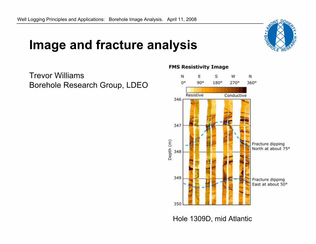
Well Logging Principles and Applications: Borehole Image Analysis. April 11, 2008
Image and fracture analysis
Trevor Williams
Borehole Research Group, LDEO
Hole 1309D, mid Atlantic

Well Logging Principles and Applications: Borehole Image Analysis. April 11, 2008
Types of downhole image tools
- Electrical Resistivity: FMS (Formation MicroScanner),
FMI (Formation MicroImager),
RAB (Resistivity-At-Bit), etc
- Ultrasonic: UBI (Ultrasonic Borehole Imager),
BHTV (BoreHole TeleViewer), etc
- Video.

Well Logging Principles and Applications: Borehole Image Analysis. April 11, 2008
Downhole video
J. Nelson, COLOG
Clear drilling fluid is required
for downhole video - not often
the case.

Well Logging Principles and Applications: Borehole Image Analysis. April 11, 2008
Unwrapped borehole images
0° 180° 360°
Well Logging Principles and Applications: Borehole Image Analysis. April 11, 2008
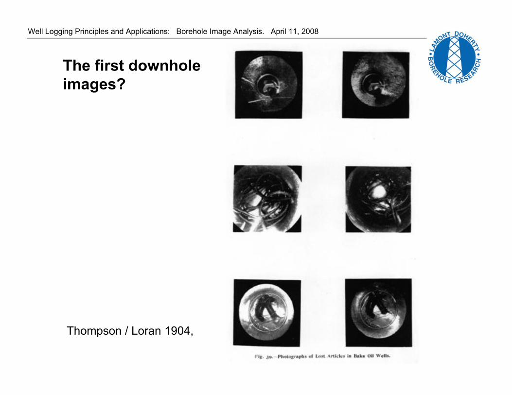
The first downhole
images?
Thompson / Loran 1904,

Well Logging Principles and Applications: Borehole Image Analysis. April 11, 2008
Downhole video
J. Nelson, COLOG

Well Logging Principles and Applications: Borehole Image Analysis. April 11, 2008
Resistivity Images
Needs water-based drilling fluid
(not oil-based)

Well Logging Principles and Applications: Borehole Image Analysis. April 11, 2008
40 cm
FMS (Formation Micro-Scanner)
Resistivity Images

Well Logging Principles and Applications: Borehole Image Analysis. April 11, 2008
FMI

Well Logging Principles and Applications: Borehole Image Analysis. April 11, 2008
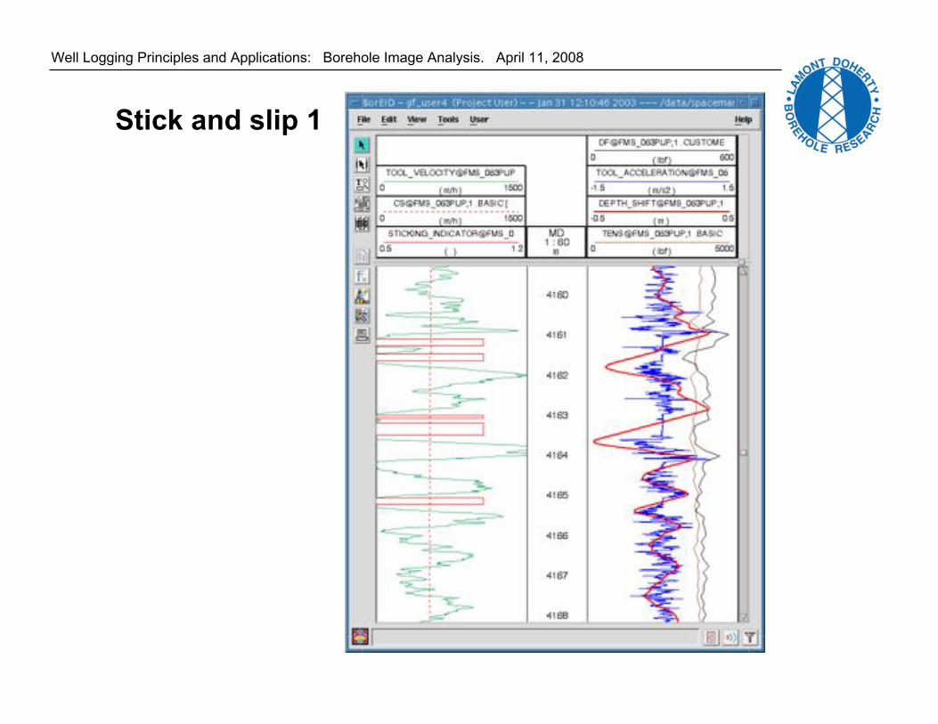
FMS Processing
Processing is required to convert the 64 electrical current traces recorded
into a color-scale resistivity image.
1. Speed correction. For "stick and slip" - irregular tool motion.
3. Button correction. e.g., "dead buttons" the defective trace is replaced
by traces from adjacent good buttons.
2. Equalization. Between button electrodes and between pads.
4. EMEX voltage correction. During logging, the voltage that drives the current
is continuously regulated so that current flows even through very resistive
formations.
Well Logging Principles and Applications: Borehole Image Analysis. April 11, 2008
Stick and slip 1

Well Logging Principles and Applications: Borehole Image Analysis. April 11, 2008
Stick and slip 2
Raw image dynamicstatic

Well Logging Principles and Applications: Borehole Image Analysis. April 11, 2008
FMS images
Site 1003,
Bahamas
Transect:
Lithostratigraphy

Well Logging Principles and Applications: Borehole Image Analysis. April 11, 2008FMS images, Site 1166, Antarctic

Well Logging Principles and Applications: Borehole Image Analysis. April 11, 2008
Iberian Margin
Bedding:
sandstone/claystone
alternations

Well Logging Principles and Applications: Borehole Image Analysis. April 11, 2008
Soft-sediment
deformation

Well Logging Principles and Applications: Borehole Image Analysis. April 11, 2008
Prilliman et al, 1977
Full 360° coverage of
the borehole wall
makes some features
much easier to
identify!
FMI and RAB images

Well Logging Principles and Applications: Borehole Image Analysis. April 11, 2008
Ultrasonic
Borehole Imager

Well Logging Principles and Applications: Borehole Image Analysis. April 11, 2008
UBI images
Hole 1256D

Well Logging Principles and Applications: Borehole Image Analysis. April 11, 2008
UBI and FMS comparison
Well Logging Principles and Applications: Borehole Image Analysis. April 11, 2008
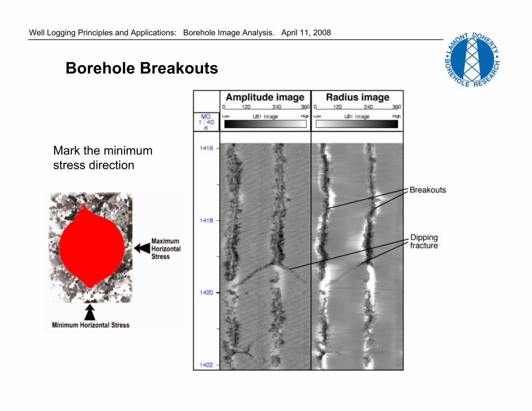
Borehole Breakouts
Mark the minimum
stress direction
Well Logging Principles and Applications: Borehole Image Analysis. April 11, 2008
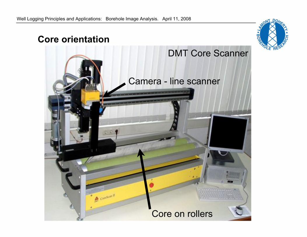
Core orientation
Core on rollers
Camera - line scanner
DMT Core Scanner

Well Logging Principles and Applications: Borehole Image Analysis. April 11, 2008
bedding
fault
Bedding and fault dip

Well Logging Principles and Applications: Borehole Image Analysis. April 11, 2008
T. Wilson
Natural
Fractures:
Past stress
conditions
Induced
Fractures:
Present stress
conditions
Natural and induced fractures

Well Logging Principles and Applications: Borehole Image Analysis. April 11, 2008
Core orientation using BHTV images
Match features in
core and
downhole image.
Then rotate core
to north.
Well Logging Principles and Applications: Borehole Image Analysis. April 11, 2008
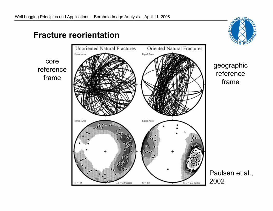
Fracture reorientation
core
reference
frame
geographic
reference
frame
Paulsen et al.,
2002

Well Logging Principles and Applications: Borehole Image Analysis. April 11, 2008
?

Well Logging Principles and Applications: Borehole Image Analysis. April 11, 2008
Vein folded
by
compaction
Example of faulting ~same age as
deposition of rock

Well Logging Principles and Applications: Borehole Image Analysis. April 11, 2008
Applications of boreole imagery
Also:
Lithostratigraphy
Bedding: structural & sedimentary dips
Paleocurrents - sed. structures
Orienting Paleomagnetic samples
Fractures in core and borehole walls, for tectonic evolution:
• faulting history
• relation fluids & deformation
• paleostress
• contemporary stress