Topics Introduction Technologies in FMC FMC with IP FMC with IMS FMC with SIP FMC with UMA.
LICE8L-HARD-1E
F2MC-8L FamilyCompact Emulator
Hardware Manual

ii
iii
PREFACE
■ Manual Objectives
The Compact Emulator is the development support tool for development and evaluation ofapplications based on the F2MC-8L family.The user to develop and evaluate applications based on the F2MC-8L family.
■ Manual Readers
This manual describes handling and connecting the Compact Emulator for engineers who will developapplications based on the F2MC-8L family using the Compact Emulator.
■ Composition of Manual
Read this manual before operating Compact Emulator.This manual has four chapters.
Chapter 1 Product HandlingThis chapter describes the configuration and handling of the Compact Emulator emulation unit.
Chapter 2 Product DescriptionThis chapter describes the hardware configuration, the names of components, and specificationsfor the Compact Emulator unit.
Chapter 3 Settings and ConnectionsThis chapter describes various settings and connections of the Compact Emulator unit beforepower-on.
Chapter 4 HardwareThis chapter the power-on/-off sequence for the Compact Emulator unit and the correspondencebetween the probe cable and evaluation MCU.

iv
How To Read This Manual
■ Page Construction
Each section in this manual is made up of one page or double-spread pages, so that you can look atthe contents of the section without turning pages. Also, the summary under the title in each sectionwill help you understand the section outline.The construction of spread pages is shown below.
■ Spread Pages
v
Contents
CHAPTER 1 PRODUCT HANDLING ........................................................ 1
1.1 Checking Accessories .................................................................................... 2
1.2 Options ........................................................................................................... 3
1.3 Precautions in Use ......................................................................................... 4
CHAPTER 2 PRODUCT DESCRIPTION................................................. 5
2.1 Hardware Configuration.................................................................................. 6
2.2 External Views and Names of Components ................................................... 7
2.3 Specifications for Compact Emulator Unit ...................................................... 9
2.4 Specifications for DIP-28P Probe Cable....................................................... 10
2.5 Specifications for RS-232C .......................................................................... 11
CHAPTER 3 SETTINGS AND CONNECTIONS .................................... 13
3.1 Connecting the Probe Cable ........................................................................ 14
3.2 Connection with User System ...................................................................... 16
3.3 Connection with Personal Computer ............................................................ 18
3.4 Connection with Power Supply..................................................................... 19
CHAPTER 4 DETAILS OF HARDWARE ............................................... 21
4.1 Power-ON/OFF Sequence ........................................................................... 22
APPENDIX ............................................................................................... 23
Appendix A LED Messages..................................................................................... 24
Appendix B Specifications of Optional Probe Cable (Piggyback/Evaluation) .................... 25

vi
1
CHAPTER 1 PRODUCT HANDLING
This chapter describes the configuration and handling of the Compact Emulator unit.
1.1 Checking Accessories
1.2 Options
1.3 Precautions in Use
2
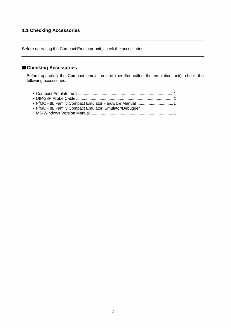
1.1 Checking Accessories
Before operating the Compact Emulator unit, check the accessories.
■ Checking Accessories
Before operating the Compact emulation unit (herafter called the emulation unit), check thefollowing accessories.
• Compact Emulator unit .....................................................................................1• DIP-28P Probe Cable .......................................................................................1• F2MC - 8L Family Compact Emulator Hardware Manual .................................1• F2MC - 8L Family Compact Emulator, Emulator/Debugger
MS-Windows Version Manual ..........................................................................1

3
1.2 Options
The Compact Emulator unit requires the following various options in Tables 1-1 and 1-2. The useshould buy them separately as needed.
■ Options
The Compact Emulator unit does not operate by itself. It requires an emulator debugger, probecable, and evaluation MCU.The user should buy the options in Table 1-1 separately as needed.
Table 1-1 Options
Name Model number
Emulator debugger —
Probe cable*1 MSE-2144-xxx
Evaluation MCU*2 MB89PVxxx
RS-232C cable (modem cable)*3 —
*1: The model number varies with each package (see Table 1-2).*2: The F2MC-8L evaluation MCU must be capable of working with the user system.*3: Prepare separately the cable compatible to your personal computer.
Table 1-2 Probe Cable
Name Model number
DIP-28 probe cable MSE-2144-201
LCC-32A probe cable MSE-2144-202
LCC-32B probe cable MSE-2144-203
4
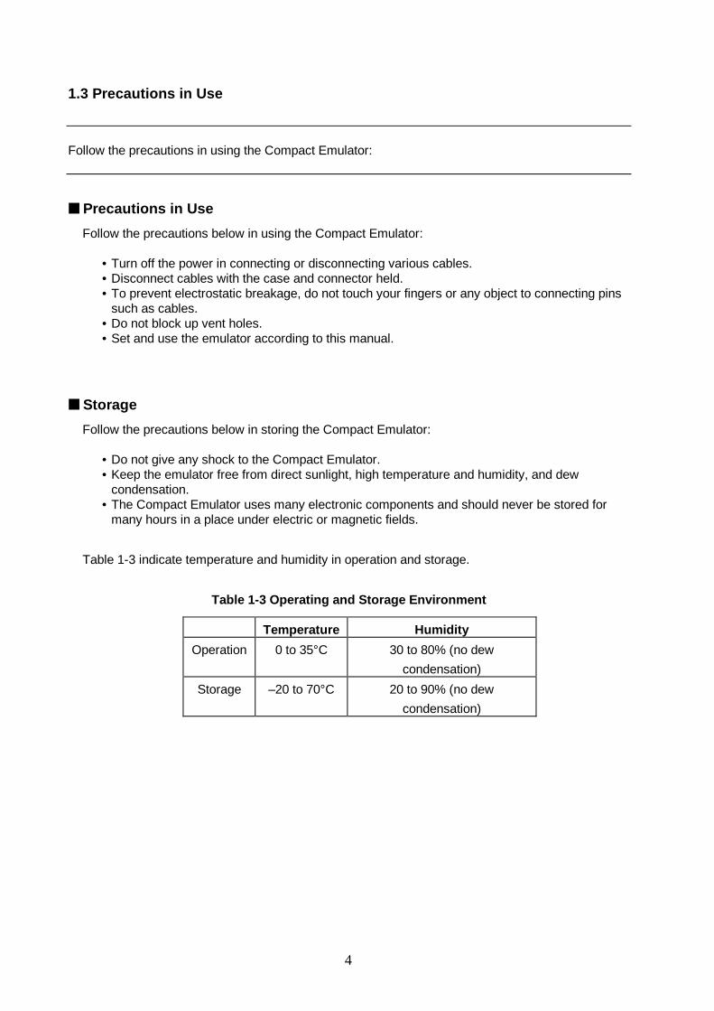
1.3 Precautions in Use
Follow the precautions in using the Compact Emulator:
■ Precautions in Use
Follow the precautions below in using the Compact Emulator:
• Turn off the power in connecting or disconnecting various cables.• Disconnect cables with the case and connector held.• To prevent electrostatic breakage, do not touch your fingers or any object to connecting pins
such as cables.• Do not block up vent holes.• Set and use the emulator according to this manual.
■ Storage
Follow the precautions below in storing the Compact Emulator:
• Do not give any shock to the Compact Emulator.• Keep the emulator free from direct sunlight, high temperature and humidity, and dew
condensation.• The Compact Emulator uses many electronic components and should never be stored for
many hours in a place under electric or magnetic fields.
Table 1-3 indicate temperature and humidity in operation and storage.
Table 1-3 Operating and Storage Environment
Temperature Humidity
Operation 0 to 35°C 30 to 80% (no dew
condensation)
Storage –20 to 70°C 20 to 90% (no dew
condensation)
5
CHAPTER 2 PRODUCT DESCRIPTION
This chapter describes the hardware configuration, the names of components, and specifications forthe emulation unit.
2.1 Hardware Configuration
2.2 External Views and Names of Components
2.3 Specifications for Compact Emulator Unit
2.4 Specifications for Probe Cable (DIP-28P)
2.5 Specifications for RS-232C
6
2.1 Hardware Configuration
The Compact Emulator unit can be connected to the evaluation unit provided for each MCU, theprobe cable, and the communication to build up the development support system compatible to theF2MC-8L family.
■ System Configuration
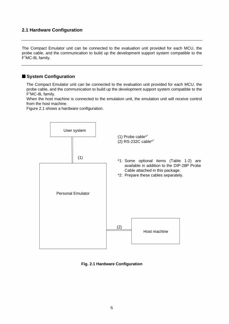
The Compact Emulator unit can be connected to the evaluation unit provided for each MCU, theprobe cable, and the communication to build up the development support system compatible to theF2MC-8L family.When the host machine is connected to the emulation unit, the emulation unit will receive controlfrom the host machine.Figure 2.1 shows a hardware configuration.
Fig. 2.1 Hardware Configuration
(1) Probe cable*1
(2) RS-232C cable*2
*1: Some optional items (Table 1-2) areavailable in addition to the DIP-28P ProbeCable attached in this package.
*2: Prepare these cables separately.
(1)
(2)Host machine
User system
Personal Emulator
7
2.2 External Views and Names of Components
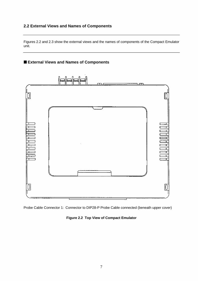
Figures 2.2 and 2.3 show the external views and the names of components of the Compact Emulatorunit.
■ External Views and Names of Components
Probe Cable Connector 1: Connector to DIP28-P Probe Cable connected (beneath upper cover)
Figure 2.2 Top View of Compact Emulator
8
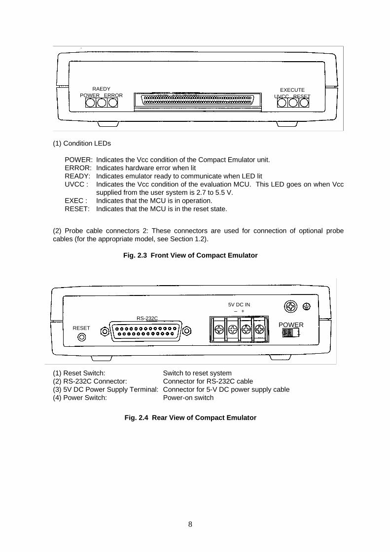
(1) Condition LEDs
POWER: Indicates the Vcc condition of the Compact Emulator unit.ERROR: Indicates hardware error when litREADY: Indicates emulator ready to communicate when LED litUVCC : Indicates the Vcc condition of the evaluation MCU. This LED goes on when Vcc
supplied from the user system is 2.7 to 5.5 V.EXEC : Indicates that the MCU is in operation.RESET: Indicates that the MCU is in the reset state.
(2) Probe cable connectors 2: These connectors are used for connection of optional probecables (for the appropriate model, see Section 1.2).
Fig. 2.3 Front View of Compact Emulator
(1) Reset Switch: Switch to reset system(2) RS-232C Connector: Connector for RS-232C cable(3) 5V DC Power Supply Terminal: Connector for 5-V DC power supply cable(4) Power Switch: Power-on switch
Fig. 2.4 Rear View of Compact Emulator
EXECUTEUVCC RESET
RAEDYPOWER ERROR
POWER0 1
RS-232C
5V DC IN– +
RESET
9
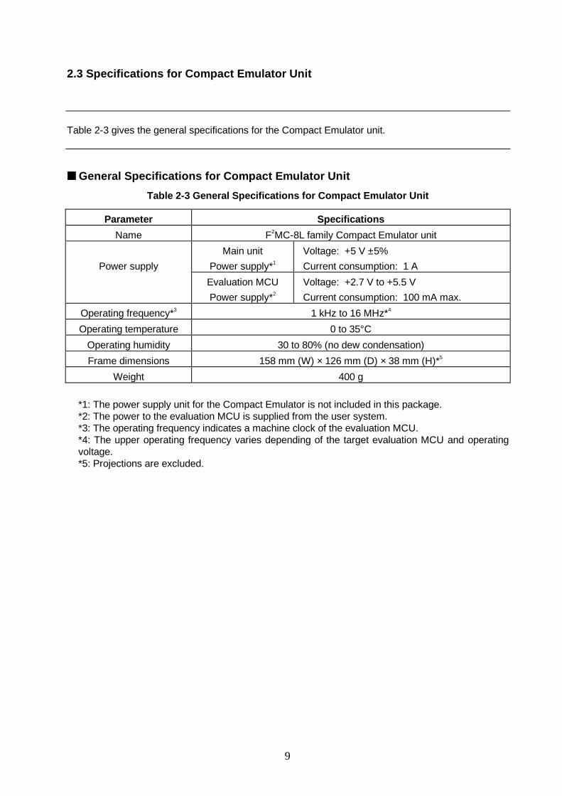
2.3 Specifications for Compact Emulator Unit
Table 2-3 gives the general specifications for the Compact Emulator unit.
■ General Specifications for Compact Emulator Unit
Table 2-3 General Specifications for Compact Emulator Unit
Parameter Specifications
Name F2MC-8L family Compact Emulator unit
Power supply
Main unit
Power supply*1
Voltage: +5 V ±5%
Current consumption: 1 A
Evaluation MCU
Power supply*2
Voltage: +2.7 V to +5.5 V
Current consumption: 100 mA max.
Operating frequency*3 1 kHz to 16 MHz*4
Operating temperature 0 to 35°C
Operating humidity 30 to 80% (no dew condensation)
Frame dimensions 158 mm (W) × 126 mm (D) × 38 mm (H)*5
Weight 400 g
*1: The power supply unit for the Compact Emulator is not included in this package.*2: The power to the evaluation MCU is supplied from the user system.*3: The operating frequency indicates a machine clock of the evaluation MCU.*4: The upper operating frequency varies depending of the target evaluation MCU and operatingvoltage.*5: Projections are excluded.
10
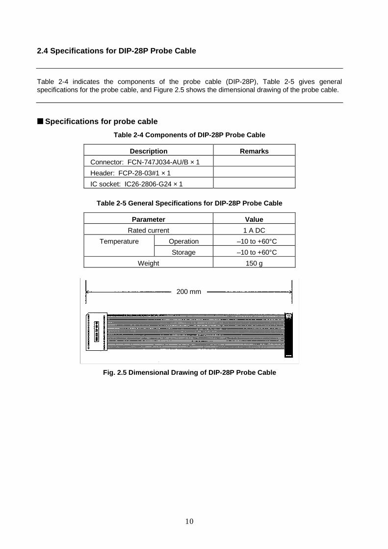
2.4 Specifications for DIP-28P Probe Cable
Table 2-4 indicates the components of the probe cable (DIP-28P), Table 2-5 gives generalspecifications for the probe cable, and Figure 2.5 shows the dimensional drawing of the probe cable.
■ Specifications for probe cable
Table 2-4 Components of DIP-28P Probe Cable
Description Remarks
Connector: FCN-747J034-AU/B × 1
Header: FCP-28-03#1 × 1
IC socket: IC26-2806-G24 × 1
Table 2-5 General Specifications for DIP-28P Probe Cable
Parameter Value
Rated current 1 A DC
Temperature Operation –10 to +60°C
Storage –10 to +60°C
Weight 150 g
Fig. 2.5 Dimensional Drawing of DIP-28P Probe Cable
200 mm
11
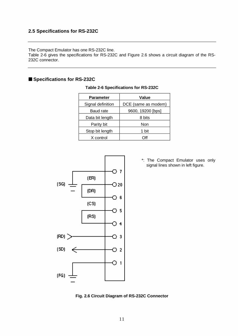
2.5 Specifications for RS-232C
The Compact Emulator has one RS-232C line.Table 2-6 gives the specifications for RS-232C and Figure 2.6 shows a circuit diagram of the RS-232C connector.
■ Specifications for RS-232C
Table 2-6 Specifications for RS-232C
Parameter Value
Signal definition DCE (same as modem)
Baud rate 9600, 19200 [bps]
Data bit length 8 bits
Parity bit Non
Stop bit length 1 bit
X control Off
Fig. 2.6 Circuit Diagram of RS-232C C onnector
*: The Compact Emulator uses onlysignal lines shown in left figure.

12
MEMO

13
CHAPTER 3 SETTINGS AND CONNECTIONS
This chapter describes various settings and connections of the emulation unit before power on.For the names of components, see 2.2 EXTERNAL VIEWS AND NAMES OF COMPONENTS .
3.1 Connecting the Probe Cable3.2 Connection with User System3.3 Connection with Personal Computer3.4 Connection with Power Supply
14
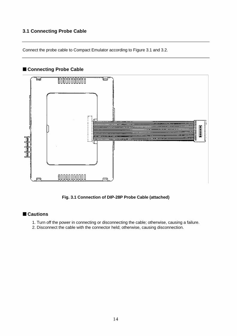
3.1 Connecting Probe Cable
Connect the probe cable to Compact Emulator according to Figure 3.1 and 3.2.
■ Connecting Probe Cable
Fig. 3.1 Connection of DIP-28P Probe Cable (attached)
■ Cautions
1. Turn off the power in connecting or disconnecting the cable; otherwise, causing a failure.2. Disconnect the cable with the connector held; otherwise, causing disconnection.
15
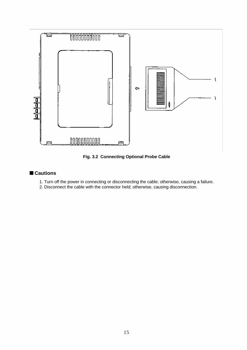
Fig. 3.2 Connecting Optional Probe Cable
■ Cautions
1. Turn off the power in connecting or disconnecting the cable; otherwise, causing a failure.2. Disconnect the cable with the connector held; otherwise, causing disconnection.
16
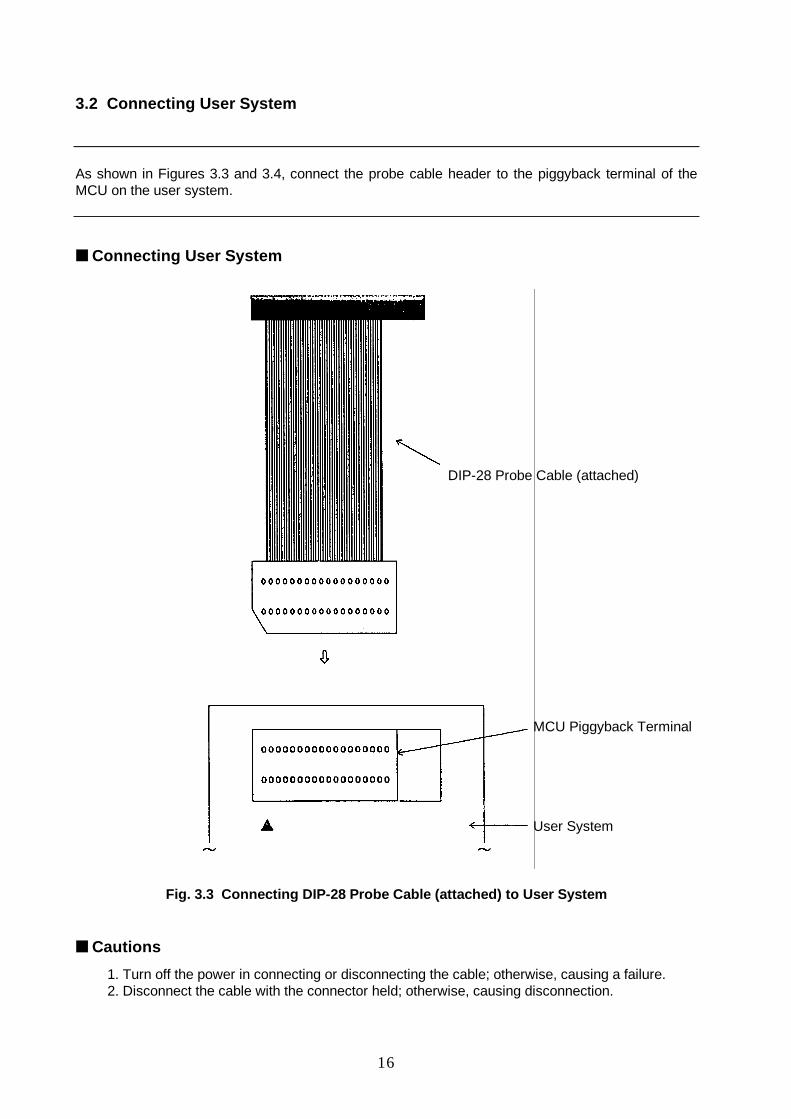
3.2 Connecting User System
As shown in Figures 3.3 and 3.4, connect the probe cable header to the piggyback terminal of theMCU on the user system.
■ Connecting User System
Fig. 3.3 Connecting DIP-28 Probe Cable (attached) to User System
■ Cautions
1. Turn off the power in connecting or disconnecting the cable; otherwise, causing a failure.2. Disconnect the cable with the connector held; otherwise, causing disconnection.
DIP-28 Probe Cable (attached)
MCU Piggyback Terminal
User System
17
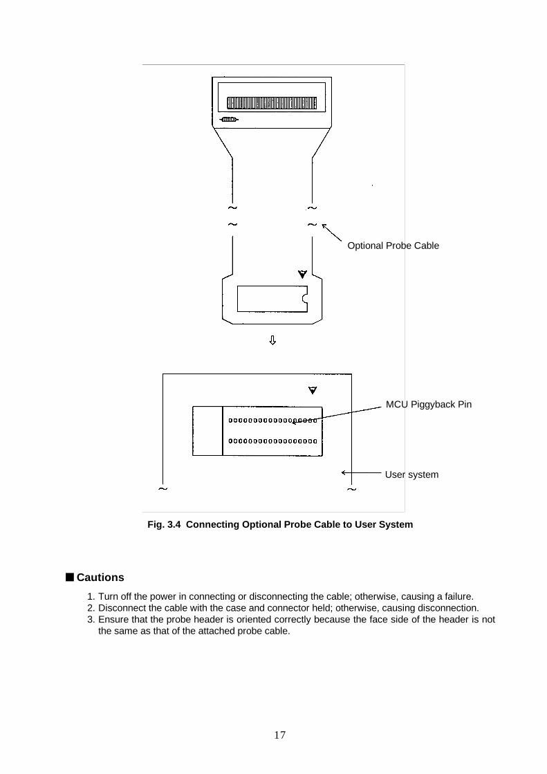
Fig. 3.4 Connecting Optional Probe Cable to User System
■ Cautions
1. Turn off the power in connecting or disconnecting the cable; otherwise, causing a failure.2. Disconnect the cable with the case and connector held; otherwise, causing disconnection.3. Ensure that the probe header is oriented correctly because the face side of the header is not
the same as that of the attached probe cable.
Optional Probe Cable
MCU Piggyback Pin
User system
18
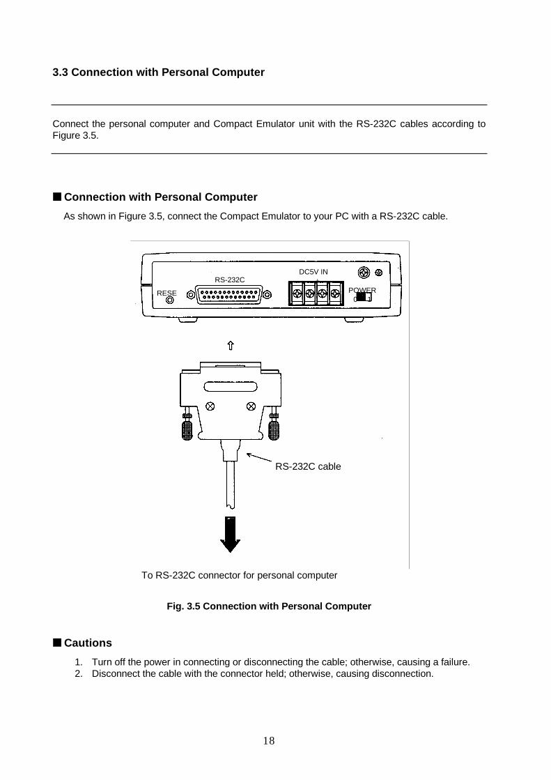
3.3 Connection with Personal Computer
Connect the personal computer and Compact Emulator unit with the RS-232C cables according toFigure 3.5.
■ Connection with Personal Computer
As shown in Figure 3.5, connect the Compact Emulator to your PC with a RS-232C cable.
To RS-232C connector for personal computer
Fig. 3.5 Connection with Personal Computer
■ Cautions
1. Turn off the power in connecting or disconnecting the cable; otherwise, causing a failure.2. Disconnect the cable with the connector held; otherwise, causing disconnection.
RS-232C cable
DC5V IN– +
POWER0 1
RS-232C
RESE
19
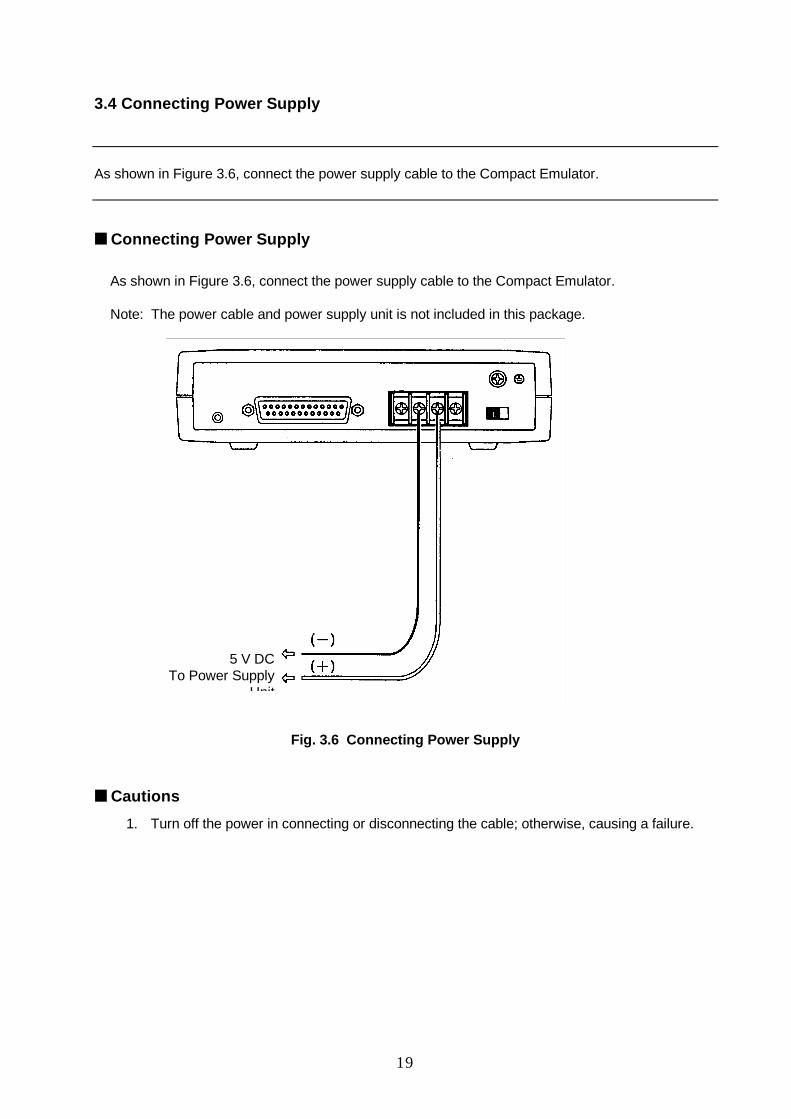
3.4 Connecting Power Supply
As shown in Figure 3.6, connect the power supply cable to the Compact Emulator.
■ Connecting Power Supply
As shown in Figure 3.6, connect the power supply cable to the Compact Emulator.
Note: The power cable and power supply unit is not included in this package.
Fig. 3.6 Connecting Power Supply
■ Cautions
1. Turn off the power in connecting or disconnecting the cable; otherwise, causing a failure.
5 V DCTo Power Supply
Unit

20
MEMO
21
CHAPTER 4 DETAILS OF HARDWARE
This chapter describes the details of hardware of Compact Emulator.
4.1 Power-ON/OFF Sequence
22
4.1 Power-ON/OFF Sequence
This section describes the power-ON/OFF sequence.
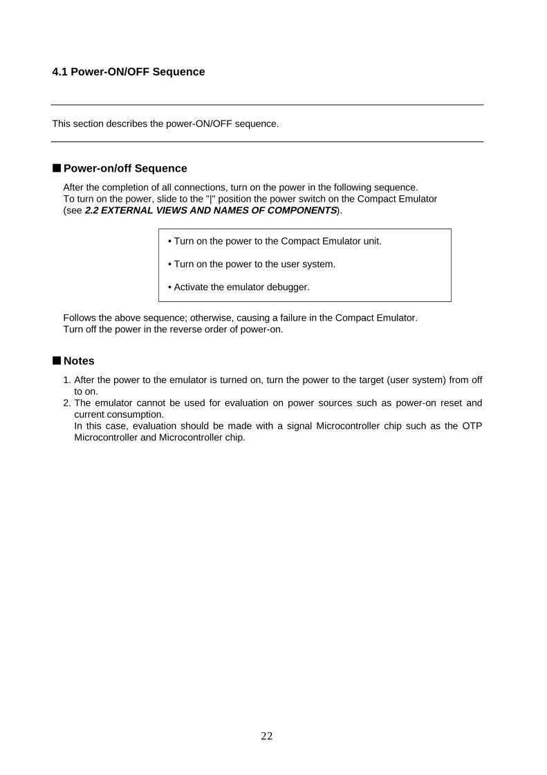
■ Power-on/off Sequence
After the completion of all connections, turn on the power in the following sequence.To turn on the power, slide to the "|" position the power switch on the Compact Emulator(see 2.2 EXTERNAL VIEWS AND NAMES OF COMPONENTS ).
• Turn on the power to the Compact Emulator unit.
• Turn on the power to the user system.
• Activate the emulator debugger.
Follows the above sequence; otherwise, causing a failure in the Compact Emulator.Turn off the power in the reverse order of power-on.
■ Notes
1. After the power to the emulator is turned on, turn the power to the target (user system) from offto on.
2. The emulator cannot be used for evaluation on power sources such as power-on reset andcurrent consumption.In this case, evaluation should be made with a signal Microcontroller chip such as the OTPMicrocontroller and Microcontroller chip.
23
APPENDIX
This appendixes indicate the LED messages of Compact Emulator and specifications of optionalprobe cable.
APPENDIX A LED MessagesAPPENDIX B Specifications of Optional Probe Cable (Piggyback/Evaluation)
24
APPENDIX A LED Messages
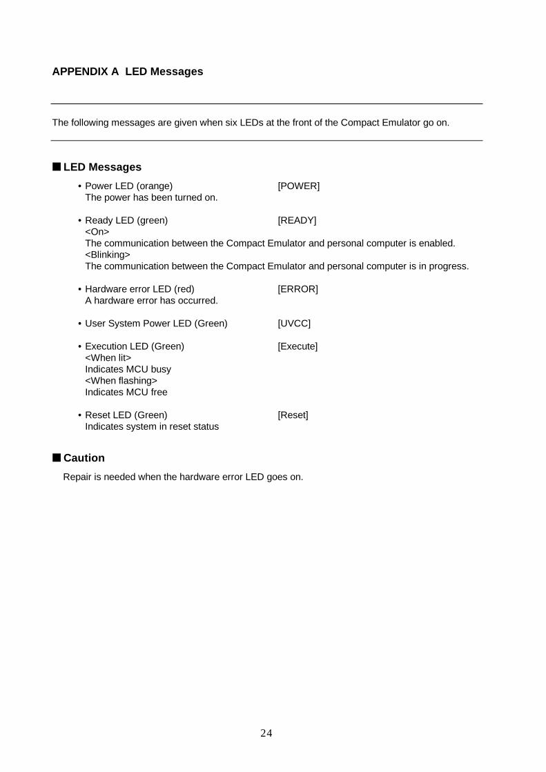
The following messages are given when six LEDs at the front of the Compact Emulator go on.
■ LED Messages
• Power LED (orange) [POWER]The power has been turned on.
• Ready LED (green) [READY]<On>The communication between the Compact Emulator and personal computer is enabled.<Blinking>The communication between the Compact Emulator and personal computer is in progress.
• Hardware error LED (red) [ERROR]A hardware error has occurred.
• User System Power LED (Green) [UVCC]
• Execution LED (Green) [Execute]<When lit>Indicates MCU busy<When flashing>Indicates MCU free
• Reset LED (Green) [Reset]Indicates system in reset status
■ Caution
Repair is needed when the hardware error LED goes on.
25
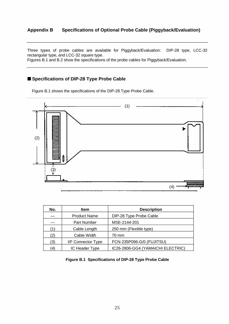
Appendix B Specifications of Optional Probe Cable (Piggyback/Evaluation)
Three types of probe cables are available for Piggyback/Evaluation: DIP-28 type, LCC-32rectangular type, and LCC-32 square type.Figures B.1 and B.2 show the specifications of the probe cables for Piggyback/Evaluation.
■ Specifications of DIP-28 Type Probe Cable
Figure B.1 shows the specifications of the DIP-28 Type Probe Cable.
No. Item Description
— Product Name DIP-28 Type Probe Cable
— Part Number MSE-2144-201
(1) Cable Length 250 mm (Flexible type)
(2) Cable Width 70 mm
(3) I/F Connector Type FCN-235P096-G/0 (FUJITSU)
(4) IC Header Type IC26-2806-GG4 (YAMAICHI ELECTRIC)
Figure B.1 Specifications of DIP-28 Type Probe Cable
(4)
(3)
(2)
(1)

26
■ Specifications of LCC-32 Type Probe Cable
Figure B.2 shows the specifications of the LCC-32 Type Probe Cable.
No. Item Description
— Product Name LCC-32 Type A (B) Probe Cable
— Part Number LCC-32 Type A: MSE-2144-202
LCC-32 Type B: MSE-2144-203
(1) Cable Length 250 mm (Flexible type)
(2) Length of Folded Portion 60 mm
(3) Cable Width 70 mm
(4) I/F Connector Type FCN-235P096-G/0 (FUJITSU)
(5) I/F Header Type LCC-32 Type A: HMBSTMF64-01T6 (Kyocera)
LCC-32 Type B: HMBSTMF48-02T02
(Kyocera)
Fig. B.2 Specifications of LCC-32 Type Probe Cable
(5)
(4)
(2)
(3)
(1)