![Untitled-1 [bscplre.com]bscplre.com/wp-content/uploads/2016/01/Hillside-2_e...A MEGA LIFE WHERE HAPP Welcome to a life that supersedes all expectati where luxury is a default specification](https://static.fdocuments.us/doc/165x107/5f46de900324547bc965b097/untitled-1-a-mega-life-where-happ-welcome-to-a-life-that-supersedes-all.jpg)
FM_355-2_e
244
SIMATIC Temperature regulator FM 355-2 __ __ __ __ __ __ __ __ __ __ __ __ __ __ __ __ __ __ __ __ __ __ __ __ __ __ __ __ __ __ __ __ __ __ __ __ __ __ __ __ __ __ __ __ __ __ __ __ __ __ __ __ __ __ __ __ __ __ __ __ __ __ __ __ __ __ __ __ __ __ __ __ __ __ __ __ Preface Product Overview 1 Structure of the FM 355-2 2 Installing and removing the FM 355-2 3 Wiring the FM 355-2 4 Installing the configuration package 5 How does the FM 355-2 control? 6 Controller optimization 7 Integrating the FM 355-2 into the user program 8 Commissioning the FM 355-2 9 Properties of digital and analog inputs and outputs. 10 Connecting measuring transmitters and loads/actuators 11 Errors and diagnoses 12 Examples 13 Data sheets A Optimization status B Assignment of DBs C List of RET_VALU messages D List of abbreviations E Furthe r Information F SIMATIC Temperature regulator FM 355-2 Operating Instructions Edition 01/2006 A5E00142771-02
-
Upload
george-cristian-ceapa -
Category
Documents
-
view
217 -
download
0
Transcript of FM_355-2_e
8/11/2019 FM_355-2_e
http://slidepdf.com/reader/full/fm355-2e 1/244
SIMATIC Temperature regulator FM 355-2
______________
______________
______________
______________
______________
______________
______________
______________
______________
______________
______________
______________
______________ ______________
______________
______________
______________ ______________
______________
Preface
Product Overview
1
Structure of the FM 355-2
2
Installing and removing the
FM 355-2
3
Wiring the FM 355-2
4
Installing the configuration
package
5
How does the FM 355-2
control?
6
Controller optimization
7
Integrating the FM 355-2 into
the user program
8
Commissioning the
FM 355-2
9
Properties of digital and
analog inputs and outputs.
10
Connecting measuring
transmitters and
loads/actuators
11
Errors and diagnoses
12
Examples
13
Data sheets
A
Optimization status
B
Assignment of DBs
C
List of RET_VALU messages
D
List of abbreviations
E
Further Information
F
SIMATIC
Temperature regulator FM 355-2
Operating Instructions
Edition 01/2006
A5E00142771-02

8/11/2019 FM_355-2_e
http://slidepdf.com/reader/full/fm355-2e 2/244
afety Guidelines
This manual contains notices you have to observe in order to ensure your personal safety, as well as to preventdamage to property. The notices referring to your personal safety are highlighted in the manual by a safety alertsymbol, notices referring only to property damage have no safety alert symbol. These notices shown below aregraded according to the degree of danger.
Danger
indicates that death or severe personal injury will result if proper precautions are not taken.
Warning
indicates that death or severe personal injurymay
result if proper precautions are not taken.
Caution
with a safety alert symbol, indicates that minor personal injury can result if proper precautions are not taken.
Caution
without a safety alert symbol, indicates that property damage can result if proper precautions are not taken.
Notice
indicates that an unintended result or situation can occur if the corresponding information is not taken intoaccount.
If more than one degree of danger is present, the warning notice representing the highest degree of danger willbe used. A notice warning of injury to persons with a safety alert symbol may also include a warning relating toproperty damage.
Qualified Personnel
The device/system may only be set up and used in conjunction with this documentation. Commissioning andoperation of a device/system may only be performed by
qualified personnel
. Within the context of the safety notesin this documentation qualified persons are defined as persons who are authorized to commission, ground andlabel devices, systems and circuits in accordance with established safety practices and standards.
Prescribed Usage
Note the following:
Warning
This device may only be used for the applications described in the catalog or the technical description and only inconnection with devices or components from other manufacturers which have been approved or recommended bySiemens. Correct, reliable operation of the product requires proper transport, storage, positioning and assemblyas well as careful operation and maintenance.
Trademarks
All names identified by ® are registered trademarks of the Siemens AG. The remaining trademarks in thispublication may be trademarks whose use by third parties for their own purposes could violate the rights of the
owner.
Disclaimer of Liability
We have reviewed the contents of this publication to ensure consistency with the hardware and softwaredescribed. Since variance cannot be precluded entirely, we cannot guarantee full consistency. However, theinformation in this publication is reviewed regularly and any necessary corrections are included in subsequenteditions.
Siemens AG
Automation and DrivesPostfach 48 4890437 NÜRNBERGGERMANY
Order No.: A5E00142771-02
Edition 01/2006
Copyright © Siemens AG 2006.
Technical data subject to change

8/11/2019 FM_355-2_e
http://slidepdf.com/reader/full/fm355-2e 3/244
Temperature regulator FM 355-2Operating Instructions, Edition 01/2006, A5E00142771-02 iii
Preface
Purpose of this manual
This manual describes all steps that are necessary to use the function module FM 355-2. Itsupports a quick and effective familiarization in the FM 355-2's functionality.
Contents of the manual
This manual describes both the hardware and software of the FM 355-2. It comprises of atutorial section and a reference section (see annexes).
The manual covers the following topics:
• Controlling with the FM 355-2.
• Controller optimization
• Installing and removing the FM 355-2
• Wiring the FM 355-2
• Installing the software package
• Programming the FM 355-2
• Appendices
Basic knowledge required
To understand the manual, you require general experience in the field of automationengineering.
You will also need to know how to use computers or PC-like equipment (such asprogramming devices) under Windows operating systems.
Scope of this manual
This manual contains a description of the function module FM 355-2, as is valid at the time ofpublishing. We reserve the right to describe changes to the functionality of the FM 355-2 inform of a product information.
8/11/2019 FM_355-2_e
http://slidepdf.com/reader/full/fm355-2e 4/244
Preface
Temperature regulator FM 355-2iv Operating Instructions, Edition 01/2006, A5E00142771-02
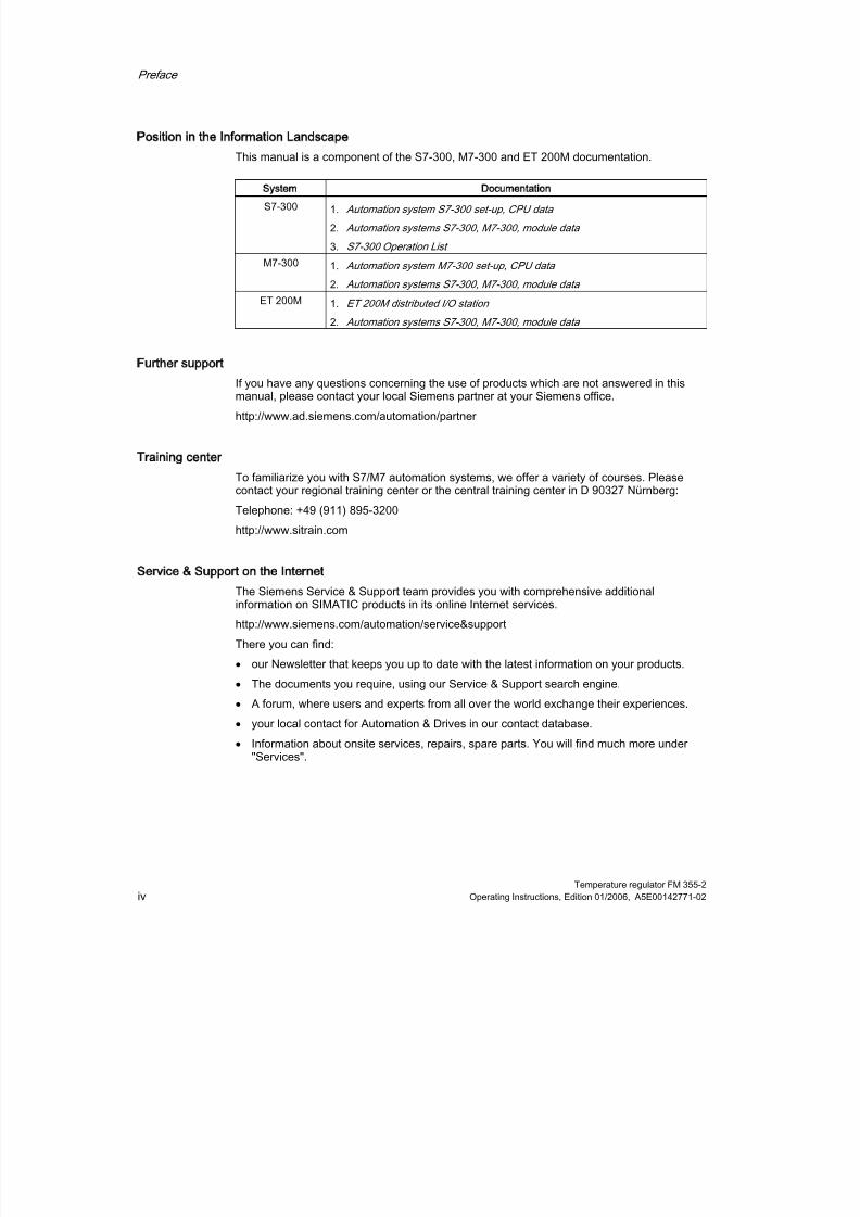
Position in the Information Landscape
This manual is a component of the S7-300, M7-300 and ET 200M documentation.
System Documentation
S7-300 1.
Automation system S7-300 set-up, CPU data
2.
Automation systems S7-300, M7-300, module data
3. S7-300 Operation List
M7-300 1.
Automation system M7-300 set-up, CPU data
2.
Automation systems S7-300, M7-300, module data
ET 200M 1.
ET 200M distributed I/O station
2.
Automation systems S7-300, M7-300, module data
Further support
If you have any questions concerning the use of products which are not answered in thismanual, please contact your local Siemens partner at your Siemens office.
http://www.ad.siemens.com/automation/partner
Training center
To familiarize you with S7/M7 automation systems, we offer a variety of courses. Pleasecontact your regional training center or the central training center in D 90327 Nürnberg:
Telephone: +49 (911) 895-3200http://www.sitrain.com
Service Support on the Internet
The Siemens Service & Support team provides you with comprehensive additionalinformation on SIMATIC products in its online Internet services.
http://www.siemens.com/automation/service&support
There you can find:
• our Newsletter that keeps you up to date with the latest information on your products.
•
The documents you require, using our Service & Support search engine.• A forum, where users and experts from all over the world exchange their experiences.
• your local contact for Automation & Drives in our contact database.
• Information about onsite services, repairs, spare parts. You will find much more under"Services".

8/11/2019 FM_355-2_e
http://slidepdf.com/reader/full/fm355-2e 5/244
Temperature regulator FM 355-2Operating Instructions, Edition 01/2006, A5E00142771-02 v
Table of contents
Preface ....................................................... ............................................................................................... iii
1 Product Overview ............................................................................................................ ....................... 1-1
1.1 Introduction ................................................................................................................................ 1-1
1.2 Functionality of the FM 355-2 .................................................................................................... 1-2
1.3 Areas of application for the FM 355-2........................................................................................ 1-4
1.4 The FM 355-2 hardware ............................................................................................................ 1-51.5 The FM 355-2 software.............................................................................................................. 1-8
2 Structure of the FM 355-2....................................................................................................................... 2-1
2.1 Basic structure of the FM 355-2................................................................................................. 2-1
2.2 Inputs of the FM 355-2............................................................................................................... 2-4
2.3 Description of the inputs ............................................................................................................ 2-42.3.1 Analog inputs ............................................................................................................................. 2-42.3.2 Digital inputs............................................................................................................................... 2-7
2.4 Outputs of the FM 355-2 ............................................................................................................ 2-7
2.5 Operative mechanism of data storage on the FM 355-2 ........................................................... 2-9
2.6 Characteristics of the FM 355-2............................................................................................... 2-13
3 Installing and removing the FM 355-2........................................................................................ ............. 3-1
3.1 Preparing for Installation............................................................................................................ 3-1
3.2 FM 355-2 installation and removal............................................................................................. 3-3
4 Wiring the FM 355-2 ......................................................................................................... ...................... 4-1
4.1 Terminal assignment on the front connector ............................................................................. 4-14.1.1 FM 355-2 C front connector ....................................................................................................... 4-14.1.2 FM 355-2 S front connector ....................................................................................................... 4-34.1.3 Special notes regarding wiring................................................................................................... 4-6
4.2 Wiring Front Connectors ............................................................................................................ 4-84.3 Module status after initial activation......................................................................................... 4-10
5 Installing the configuration package........................................................................................ ................ 5-1

8/11/2019 FM_355-2_e
http://slidepdf.com/reader/full/fm355-2e 6/244
Table of contents
Temperature regulator FM 355-2vi Operating Instructions, Edition 01/2006, A5E00142771-02
6 How does the FM 355-2 control?.............................................................................................. .............. 6-1
6.1 Overview .................................................................................................................................... 6-1
6.2 Error signal ................................................................................................................................. 6-3
6.2.1 Introduction ................................................................................................................................ 6-36.2.2 Fixed value or cascade controller .............................................................................................. 6-46.2.3 Three-component controller ....................................................................................................... 6-56.2.4 Ratio controller or composition controller................................................................................... 6-66.2.5 Signal selection for setpoints, actual values, D input and disturbance values. ......................... 6-86.2.6 Preparation actual value ............................................................................................................ 6-96.2.7 Preparation actual value ............................................................................................................ 6-96.2.8 Interrupt.................................................................................................................................... 6-10
6.3 Controller algorithm.................................................................................................................. 6-10
6.4 Description of the control algorithm ......................................................................................... 6-116.4.1 Dead zone................................................................................................................................ 6-116.4.2 PID control algorithm................................................................................................................ 6-12
6.4.3 Cooling ..................................................................................................................................... 6-186.4.4 Control zone............................................................................................................................. 6-19
6.5 Controller output....................................................................................................................... 6-206.5.1 Controller output functions ....................................................................................................... 6-206.5.2 Controller output for continuous controller ............................................................................... 6-226.5.3 Controller output with pulse controller...................................................................................... 6-236.5.4 Step controller output ............................................................................................................... 6-276.5.5 Manipulated value limits........................................................................................................... 6-28
7 Controller optimization...................................... ...................................................................................... 7-1
7.1 Overview .................................................................................................................................... 7-1
7.2 Process types............................................................................................................................. 7-2
7.3 Application area ......................................................................................................................... 7-4
7.4 Overall controller tuning process ............................................................................................... 7-5
7.5 Preparations............................................................................................................................... 7-8
7.6 Starting tuning (Phase 1 → 2)................................................................................................... 7-11
7.7 Identifying the point of inflection (Phase 2) and calculating control parameters (Phase 3, 4, 5). 7-15
7.8 Checking the process type (phase 7) ...................................................................................... 7-16
7.9 Cooling tuning .......................................................................................................................... 7-17
7.10 Tuning with step controller ....................................................................................................... 7-19
7.11 Tuning result ............................................................................................................................ 7-21
7.12 Tuning aborted by the operator................................................................................................ 7-23
7.13 Error views and corrective actions ........................................................................................... 7-24
7.14 Manual fine tuning in control mode .......................................................................................... 7-26
7.15 Parallel tuning of controller channels ....................................................................................... 7-29
7.16 Saving and retrieving controller parameters ............................................................................ 7-30

8/11/2019 FM_355-2_e
http://slidepdf.com/reader/full/fm355-2e 7/244
Table of contents
Temperature regulator FM 355-2Operating Instructions, Edition 01/2006, A5E00142771-02 vii
8 Integrating the FM 355-2 into the user program.............................................................................. ........ 8-1
8.1 Overview of the function blocks ................................................................................................. 8-1
8.2 The FB 52 FMT_PID - General .................................................................................................. 8-2
8.3 The FB 52 FMT_PID function block - Details............................................................................. 8-38.3.1 Operating via the FB 52 FMT_PID............................................................................................. 8-38.3.2 Observing via the FB 52 FMT_PID ............................................................................................ 8-48.3.3 Modify controller parameters via the FB 52 FMT_PID............................................................... 8-58.3.4 Program-controlled reparameterization ..................................................................................... 8-68.3.5 Relation between FB parameters and ....................................................................................... 8-6
8.4 The FB 53 FMT_PAR function block - General information .................................................... 8-12
8.5 The FB 54 FMT_CJ_T function block ...................................................................................... 8-16
8.6 The FB 55 FMT_DS1 function block........................................................................................ 8-17
8.7 The FB 56 FMT_TUN function block........................................................................................ 8-17
8.8 The FB 57 FMT_PV function block .......................................................................................... 8-189 Commissioning the FM 355-2................................................................................................................. 9-1
10 Properties of digital and analog inputs and outputs. ....................................................................... ...... 10-1
10.1 Properties of the digital inputs and outputs (FM 355-2 S) ....................................................... 10-1
10.2 Properties of the analog inputs ................................................................................................ 10-3
10.3 Properties of the analog outputs (FM 355-2 C) ....................................................................... 10-6
11 Connecting measuring transmitters and loads/actuators ...................................................................... 11-1
11.1 Connecting Loads/Actuators to Analog Outputs...................................................................... 11-1
11.2 Connecting measuring transmitters to analog inputs............................................................... 11-3
11.3 Use of thermocouple elements ................................................................................................ 11-6
11.4 Connecting voltage and current transducers with resistance thermometers......................... 11-11
11.5 Connecting loads/actuators to digital outputs ........................................................................ 11-14
12 Errors and diagnoses............................................................................................................................ 12-1
12.1 Fault Indication via the Group Error LED................................................................................. 12-1
12.2 Triggering diagnostic interrupts................................................................................................ 12-2
12.3 Diagnostics data records DS0 and DS1 .................................................................................. 12-3
12.4 Measuring transducer fault ...................................................................................................... 12-6
13 Examples.............................................................................................................................................. 13-1
13.1 Introduction .............................................................................................................................. 13-1
13.2 Sample application for FM 355-2 C (closed-loop controller) ................................................... 13-2
13.3 Application example for the FM 355-2 S (pulse controller)...................................................... 13-6
13.4 Application example for the FM 355-2 S (step controller) ..................................................... 13-10
13.5 Sample application for diagnostics ........................................................................................ 13-14
13.6 Operating the sample with OP 27.......................................................................................... 13-15
13.7 Example of a cascade control circuit ..................................................................................... 13-17
13.8 Example of a ratio control ...................................................................................................... 13-18
8/11/2019 FM_355-2_e
http://slidepdf.com/reader/full/fm355-2e 8/244
Table of contents
Temperature regulator FM 355-2viii Operating Instructions, Edition 01/2006, A5E00142771-02
13.9 Example of a blending control circuit ..................................................................................... 13-19
A Data sheets ............................................................................................................................................A-1
A.1 Technical Specifications S7-300................................................................................................A-1
A.2 Technical data FM 355-2 ...........................................................................................................A-3A.3 Technical data of function blocks...............................................................................................A-9
B Optimization status ......................................................................................................... ........................B-1
B.1 Optimization status.....................................................................................................................B-1
C Assignment of DBs ........................................................................................................... ......................C-1
C.1 Instance DB of the FB 52 FMT_PID...........................................................................................C-1
C.2 Instance DB of the FB 53 FMT_PAR .......................................................................................C-18
C.3 Instance DB of the FB 54 FMT_CJ_T ......................................................................................C-20
C.4 Instance DB of the FB 55 FMT_DS 1.......................................................................................C-22
C.5 Instance DB of the FB 56 FMT_TUN .......................................................................................C-23
C.6 Instance DB of the FB 57 FMT_PV..........................................................................................C-27
D List of RET_VALU messages................................................................................................... ...............D-1
D.1 List of RET_VALU messages.....................................................................................................D-1
E List of abbreviations ....................................... ........................................................................................E-1
E.1 List of abbreviations ...................................................................................................................E-1
F Further Information ......................................................................................................... ........................F-1
F.1 Literature .................................................................................................................................... F-1
F.2 Spare parts list ...........................................................................................................................F-2Index............................................................................................................................................... . Index-1
8/11/2019 FM_355-2_e
http://slidepdf.com/reader/full/fm355-2e 9/244
Table of contents
Temperature regulator FM 355-2Operating Instructions, Edition 01/2006, A5E00142771-02 ix
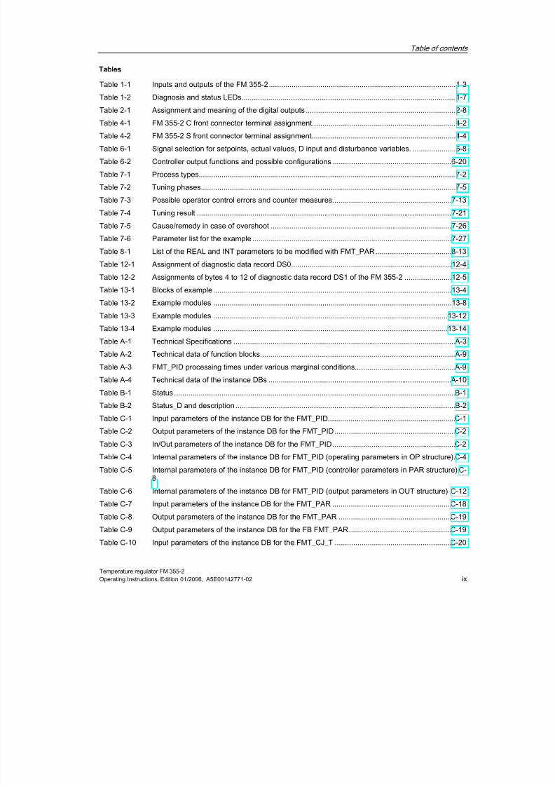
Tables
Table 1-1 Inputs and outputs of the FM 355-2........................................................................................... 1-3
Table 1-2 Diagnosis and status LEDs........................................................................................................ 1-7
Table 2-1 Assignment and meaning of the digital outputs ......................................................................... 2-8Table 4-1 FM 355-2 C front connector terminal assignment...................................................................... 4-2
Table 4-2 FM 355-2 S front connector terminal assignment...................................................................... 4-4
Table 6-1 Signal selection for setpoints, actual values, D input and disturbance variables. ..................... 6-8
Table 6-2 Controller output functions and possible configurations .......................................................... 6-20
Table 7-1 Process types............................................................................................................................. 7-2
Table 7-2 Tuning phases............................................................................................................................ 7-5
Table 7-3 Possible operator control errors and counter measures.......................................................... 7-13
Table 7-4 Tuning result ............................................................................................................................ 7-21
Table 7-5 Cause/remedy in case of overshoot ........................................................................................ 7-26
Table 7-6 Parameter list for the example................................................................................................. 7-27
Table 8-1 List of the REAL and INT parameters to be modified with FMT_PAR..................................... 8-13
Table 12-1 Assignment of diagnostic data record DS0.............................................................................. 12-4
Table 12-2 Assignments of bytes 4 to 12 of diagnostic data record DS1 of the FM 355-2 ....................... 12-5
Table 13-1 Blocks of example.................................................................................................................... 13-4
Table 13-2 Example modules .................................................................................................................... 13-8
Table 13-3 Example modules .................................................................................................................. 13-12
Table 13-4 Example modules .................................................................................................................. 13-14Table A-1 Technical Specifications ............................................................................................................A-3
Table A-2 Technical data of function blocks............................................................................................... A-9
Table A-3 FMT_PID processing times under various marginal conditions.................................................A-9
Table A-4 Technical data of the instance DBs .........................................................................................A-10
Table B-1 Status .........................................................................................................................................B-1
Table B-2 Status_D and description ...........................................................................................................B-2
Table C-1 Input parameters of the instance DB for the FMT_PID..............................................................C-1
Table C-2 Output parameters of the instance DB for the FMT_PID...........................................................C-2
Table C-3 In/Out parameters of the instance DB for the FMT_PID............................................................C-2
Table C-4 Internal parameters of the instance DB for FMT_PID (operating parameters in OP structure).C-4
Table C-5 Internal parameters of the instance DB for FMT_PID (controller parameters in PAR structure).C-8
Table C-6 Internal parameters of the instance DB for FMT_PID (output parameters in OUT structure) .C-12
Table C-7 Input parameters of the instance DB for the FMT_PAR ..........................................................C-18
Table C-8 Output parameters of the instance DB for the FMT_PAR .......................................................C-19
Table C-9 Output parameters of the instance DB for the FB FMT_PAR..................................................C-19
Table C-10 Input parameters of the instance DB for the FMT_CJ_T .........................................................C-20

8/11/2019 FM_355-2_e
http://slidepdf.com/reader/full/fm355-2e 10/244
Table of contents
Temperature regulator FM 355-2x Operating Instructions, Edition 01/2006, A5E00142771-02
Table C-11 Output parameters of the instance DB for the FMT_CJ_T.......................................................C-20
Table C-12 I/O parameters of the instance DB for the FMT_CJ_T.............................................................C-21
Table C-13 Input parameters of the instance DB for the FMT_DS1...........................................................C-22
Table C-14 Output parameters of the instance DB for the FMT_DS1 ........................................................C-22Table C-15 I/O parameters of the instance DB for the FMT_DS1 ..............................................................C-22
Table C-16 Input parameters of the instance DB for the FMT_TUN ..........................................................C-23
Table C-17 Output parameters of the instance DB for the FMT_TUN........................................................C-23
Table C-18 Input parameters of the instance DB for the FMT_TUN ..........................................................C-24
Table C-19 Internal parameters of the instance DB for the FMT_TUN (in OUT structure) ........................C-25
Table C-20 Input parameters of the instance DB for the FMT_PV .............................................................C-27
Table C-21 Output parameters of the instance DB for the FMT_PV ..........................................................C-28
Table C-22 I/O parameters of the instance DB for the FMT_PV ................................................................C-29
Table F-1 Accessories and spare parts...................................................................................................... F-2

8/11/2019 FM_355-2_e
http://slidepdf.com/reader/full/fm355-2e 11/244
Temperature regulator FM 355-2Operating Instructions, Edition 01/2006, A5E00142771-02 1-1
Product Overview
1
1.1
11Introduction
FM 355-2 models
The FM 355-2 is available in the following two versions:• FM 355-2 C (Continuous-action controller with analog outputs)
• FM 355-2 S (Step and pulse controller with digital outputs)
Order numbers
Product Delivery components Order No.:
FM 355-2 C •
Module FM 355-2 C, (continuous controller)
•
CD with configuring software, manual, GettingStarted guide, online help and examples.
6ES7355-2CH00-0AE0
FM 355-2 S •
Module FM 355-2 S (Step and pulse controller)•
CD with configuring software, manual, GettingStarted guide, online help and examples.
6ES7355-2SH00-0AE0

8/11/2019 FM_355-2_e
http://slidepdf.com/reader/full/fm355-2e 12/244
Product Overview
1.2 Functionality of the FM 355-2
Temperature regulator FM 355-21-2 Operating Instructions, Edition 01/2006, A5E00142771-02
1.2
12
Functionality of the FM 355-2
Introduction
The FM 355-2 function module is a controller module for application in the S7-300, M7-300and ET 200M automation systems.
Control method
The FM 355-2 contains a PID controller which can be configured by means of the self-optimization function:
Module Controller type Optimization by means of ...
FM 355-2 C Continuous-action controllerPulse controllerFM 355-2 S
Step controller
... the module's self-optimization function
Control structures
The FM 355-2 can be used for the following control structures:
• Regulating system
• Sequence control
• Cascade control
•
Ratio control
• Hybrid control
• Split-range control (e.g. heating / cooling)
Operating modes
The FM 355-2 supports the following operating modes:
• Automatic
• Manual (external set point)
•
Safety mode (safety set point, safety setting)• Follow-up mode
• Backup-mode (in event of CPU in STOP or CPU failure)
Number of channels
The FM 355-2 contains four independent controllers in four channels.

8/11/2019 FM_355-2_e
http://slidepdf.com/reader/full/fm355-2e 13/244

8/11/2019 FM_355-2_e
http://slidepdf.com/reader/full/fm355-2e 14/244
Product Overview
1.3 Areas of application for the FM 355-2
Temperature regulator FM 355-21-4 Operating Instructions, Edition 01/2006, A5E00142771-02
1.3
13
Areas of application for the FM 355-2
Where can you use the FM 355-2?
Die FM 355-2 is a controller module that is especially designed for temperature control.
Areas of application
The application area of the FM 355-2 includes among other things, the following branches:
• General machine construction
• Plant construction
• Industrial furnaces
•
Cooling and heating unit construction
• Food and beverage industry
• Process engineering
• Environmental technology
• Glass and ceramics manufacture
• Rubber and plastics machines
• Wood and paper processing industry
8/11/2019 FM_355-2_e
http://slidepdf.com/reader/full/fm355-2e 15/244
Product Overview
1.4 The FM 355-2 hardware
Temperature regulator FM 355-2Operating Instructions, Edition 01/2006, A5E00142771-02 1-5
1.4
14
The FM 355-2 hardware
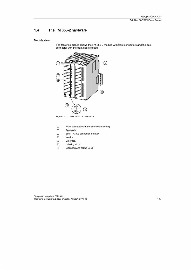
Module view
The following picture shows the FM 355-2 module with front connectors and the busconnector with the front doors closed.
Figure 1-1 FM 355-2 module view
① Front connector with front connector coding
② Type plate
③ SIMATIC bus connector interface
④ Version
⑤ Order No.:
⑥ Labeling strips
⑦ Diagnosis and status LEDs

8/11/2019 FM_355-2_e
http://slidepdf.com/reader/full/fm355-2e 16/244
Product Overview
1.4 The FM 355-2 hardware
Temperature regulator FM 355-21-6 Operating Instructions, Edition 01/2006, A5E00142771-02
Front connectors
The FM 355-2 offers the following connection facilities via the front connector:
•
8 digital inputs• 4 analog inputs
• 1 differential element input
• 8 digital outputs (FM 355-2 S only)
• 4 analog outputs (FM 355-2 C only)
• Supply voltages DC 24 V between L+ and M to feed the module and the digital andanalog outputs
• Reference point of measuring circuit MANA
The front connectors are to be ordered separately (see annex "replacement parts list").
Front connector coding
When the front connector is pressed into the operating position from the wiring position, thefront connector coding will snap into place. Subsequently the front connector can only beattached to an FM 355-2.
Labeling strips
The module comes with two labeling strips that can be individually labeled with your signalnames.
The inner sides of the front doors are labeled with the appropriate connection assignment.
Order number and version
The order number and the FM 355-2 version are detailed on the lower end of the left handfront door.
Bus connectors
The communication within a S7-300 row takes place via the bus connector. The busconnector is supplied with the FM 355-2.

8/11/2019 FM_355-2_e
http://slidepdf.com/reader/full/fm355-2e 17/244
Product Overview
1.4 The FM 355-2 hardware
Temperature regulator FM 355-2Operating Instructions, Edition 01/2006, A5E00142771-02 1-7
Diagnosis and status LEDs
The FM 355-2 has 10 LEDs, that serve diagnostic purposes and display the status of the FM
355-2 and the digital inputs.
Table 1-2 Diagnosis and status LEDs
Labeling Color Function
SF red Group error
Backup Yellow Back-up mode display
I0 green Status of digital input IO
I1 green Status of digital input I1
I2 green Status of digital input I2
I3 green Status of digital input I3
I4 green Status of digital input I4I5 green Status of digital input I5
I6 green Status of digital input I6
I7 green Status of digital input I7
The LEDs next to the FM 355-2 S binary outputs are not controlled and are of no concern.

8/11/2019 FM_355-2_e
http://slidepdf.com/reader/full/fm355-2e 18/244
Product Overview
1.5 The FM 355-2 software
Temperature regulator FM 355-21-8 Operating Instructions, Edition 01/2006, A5E00142771-02
1.5
15
The FM 355-2 software
FM 355-2 software package
In order to integrate the FM 355-2 into the S7-300, you will need the software package whichis supplied with the module on a CD. The software package comprises of the followingcomponents
• Configuration software
• Function blocks
• Online help
• Examples
Configuration software
The configuring software is to be installed on your PG/PC and called from within STEP 7.The parameters can be set via the configuring software.
The configuring software on your PG/PC enables FM 355-2
• parameterize,
• optimize,
• operation and monitoring.
Online help
You will find further information on configuration in the integrated online help (F1) or in thehelp menu > help subjects
Software for the S7-300-CPU (function blocks)
The software for the CPU comprises of the following function blocks:
Function block Effect
FB 52 FMT_PID For operating, monitoring and online controller parameter changes.
FB 53 FMT_PAR For changing further parameters online.
FB 54 FMT_CJ_T For reading and writing the differential element temperature.FB 55 FMT_DS1 For reading the diagnostic data record DS1.
FB 56 FMT_TUN For supporting the controller optimization.
FB 57 FMT_PV For reading or writing process values (analog and digital input values) forsupporting commissioning tasks.
In order to be able to use the function blocks supplied in the "FM 355-2 Temp Control"library, your CPU must support DPV1 functionalities.
S7-400 CPUs and the CPU 318-2 support the DPV1 master functionality as of firmwareversion 3.0.
412-2 PCI CPUs and the 416-2 PCI of WinAC slot also support the DPV1 masterfunctionality as of firmware version 3.0.

8/11/2019 FM_355-2_e
http://slidepdf.com/reader/full/fm355-2e 19/244
Product Overview
1.5 The FM 355-2 software
Temperature regulator FM 355-2Operating Instructions, Edition 01/2006, A5E00142771-02 1-9
In the S7-300 family, the CPUs with MMC support the DPV1 master functionality as offirmware version 2.0.CPs 443-5 with the order numbers 6GK7 443-5DX03-0XE0 and 6GK7 443-5DX04-0XE0
also support the DPV1 master functionality.If your CPU does not fulfill these conditions, you can use the old library "FM 355-2 TempControl". This library is located in the directory:
..\ Siemens\Step7\S7LIBS\old_using_SFC5859\fm_355_2
Figure 1-2 Configuration of a SIMATIC S7-300 with FM 355-2
① Programming device (PG) with STEP 7 and configuring software
② FM 355-2
③ CPU with user program and FBs of FM 355-2

8/11/2019 FM_355-2_e
http://slidepdf.com/reader/full/fm355-2e 20/244
Product Overview
1.5 The FM 355-2 software
Temperature regulator FM 355-21-10 Operating Instructions, Edition 01/2006, A5E00142771-02

8/11/2019 FM_355-2_e
http://slidepdf.com/reader/full/fm355-2e 21/244
Temperature regulator FM 355-2Operating Instructions, Edition 01/2006, A5E00142771-02 2-1
Structure of the FM 355-2
2
2.1
21Basic structure of the FM 355-2
Introduction
The FM 355-2 C and FM 355-2 S have a similar basic structure. They comprise of thefollowing function blocks:
• Inputs of the FM 355-2
– 4 analog inputs with analog value processing
– 1 differential element input for the compensation of thermal elements
– 8 digital inputs
• Controller
– 4 independent controller channels, each subdivided into the groups error signal,control algorithm, and controller output
•
Outputs of the FM 355-2 – 4 analog outputs (FM 355-2 C only)
– 8 digital outputs (FM 355-2 S only)
8/11/2019 FM_355-2_e
http://slidepdf.com/reader/full/fm355-2e 22/244
Structure of the FM 355-2
2.1 Basic structure of the FM 355-2
Temperature regulator FM 355-22-2 Operating Instructions, Edition 01/2006, A5E00142771-02
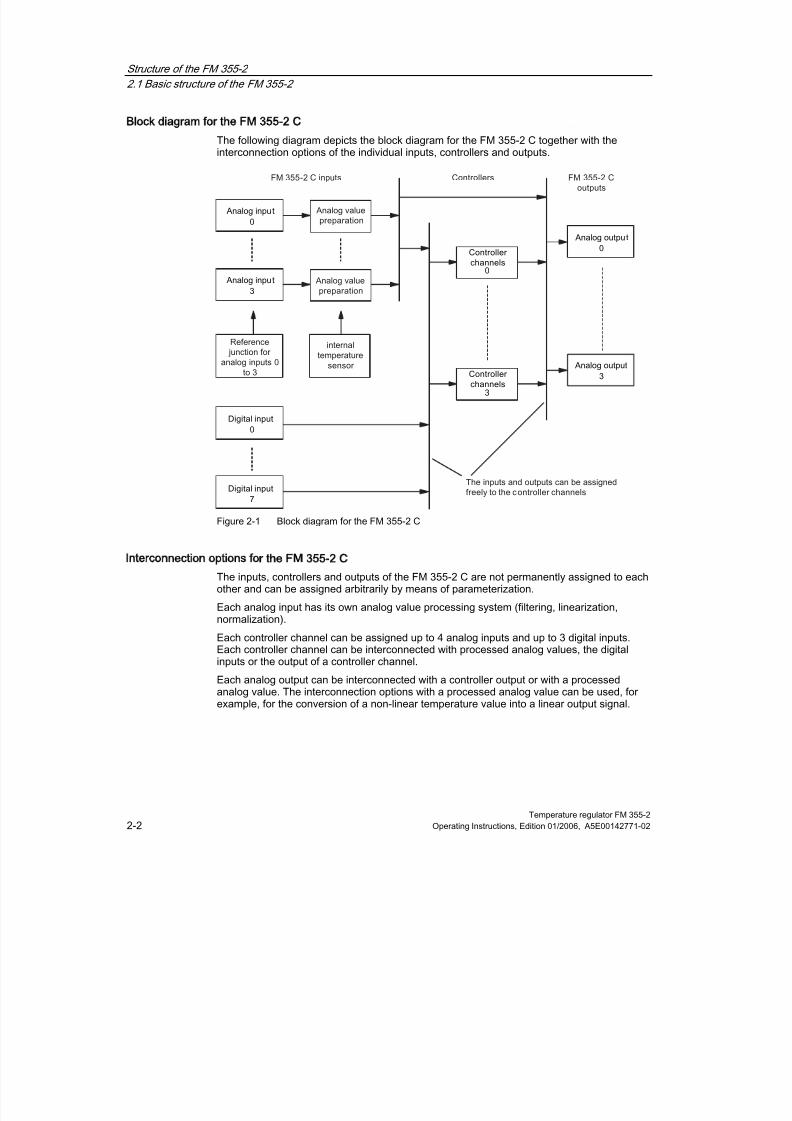
Block diagram for the FM 355-2 C
The following diagram depicts the block diagram for the FM 355-2 C together with the
interconnection options of the individual inputs, controllers and outputs.
Figure 2-1 Block diagram for the FM 355-2 C
Interconnection options for the FM 355-2 C
The inputs, controllers and outputs of the FM 355-2 C are not permanently assigned to eachother and can be assigned arbitrarily by means of parameterization.
Each analog input has its own analog value processing system (filtering, linearization,normalization).
Each controller channel can be assigned up to 4 analog inputs and up to 3 digital inputs.Each controller channel can be interconnected with processed analog values, the digitalinputs or the output of a controller channel.
Each analog output can be interconnected with a controller output or with a processedanalog value. The interconnection options with a processed analog value can be used, forexample, for the conversion of a non-linear temperature value into a linear output signal.

8/11/2019 FM_355-2_e
http://slidepdf.com/reader/full/fm355-2e 23/244
Structure of the FM 355-2
2.1 Basic structure of the FM 355-2
Temperature regulator FM 355-2Operating Instructions, Edition 01/2006, A5E00142771-02 2-3
Block diagram for the FM 355-2 S
The following diagram depicts the block diagram for the FM 355-2 S together with the
interconnection options of the individual inputs, controllers and outputs.
Figure 2-2 Block diagram for the FM 355-2 S
Interconnection options for the FM 355-2 S
The inputs and controllers of the FM 355-2 S are not permanently assigned to each otherand can be assigned arbitrarily by means of parameterization.
The 4 controller channels are permanently assigned to 2 digital outputs each.
Each analog input has its own analog value processing system (filtering, linearization,normalization).
Each controller channel can be assigned up to 4 analog inputs and up to 5 digital inputs.Each controller channel can be interconnected with processed analog values, the digitalinputs or the output of a controller channel.
See also
Overview (Page 6-1)
8/11/2019 FM_355-2_e
http://slidepdf.com/reader/full/fm355-2e 24/244
Structure of the FM 355-2
2.2 Inputs of the FM 355-2
Temperature regulator FM 355-22-4 Operating Instructions, Edition 01/2006, A5E00142771-02
2.2
22
Inputs of the FM 355-2
The FM 355-2 C and FM 355-2 S have the same structure in terms of their analog and digital
inputs.
2.3
23
Description of the inputs
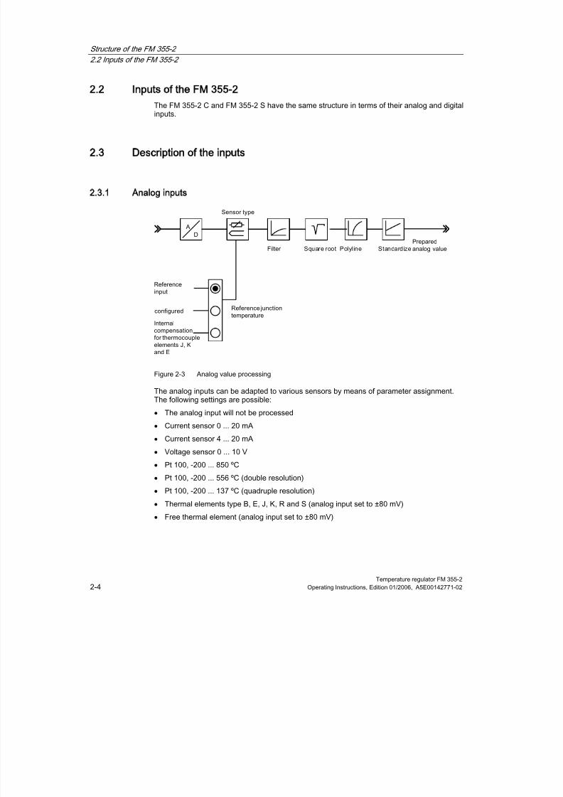
2.3.1 Analog inputs
Figure 2-3 Analog value processing
The analog inputs can be adapted to various sensors by means of parameter assignment.The following settings are possible:
• The analog input will not be processed
• Current sensor 0 ... 20 mA
• Current sensor 4 ... 20 mA
• Voltage sensor 0 ... 10 V
• Pt 100, -200 ... 850 ºC
• Pt 100, -200 ... 556 ºC (double resolution)
• Pt 100, -200 ... 137 ºC (quadruple resolution)
• Thermal elements type B, E, J, K, R and S (analog input set to ±80 mV)
• Free thermal element (analog input set to ±80 mV)
8/11/2019 FM_355-2_e
http://slidepdf.com/reader/full/fm355-2e 25/244
Structure of the FM 355-2
2.3 Description of the inputs
Temperature regulator FM 355-2Operating Instructions, Edition 01/2006, A5E00142771-02 2-5
Adaptation to line frequency
The input signal processing system can be adapted to the line frequency in order to
surprises errors in the measurement of analog signals. The following settings are possible:• 50 Hz operation
• 60 Hz operation
Switchover Celsius / Fahrenheit
Temperatures can be measured in either °C or °F. The reference junction temperature is notconverted if changing from °C to °F.
Reference junction
The following can be assigned:• Reference input: When a thermal element has been set up on an analog input, you can
connect a Pt 100 to the FM 355-2 differential element input to compensate for thedifferential element temperature of thermal elements.
If you use the differential element input, the sampling time for all of the controllers will beincreased by the conversion time for the differential element input (see diagram"Sequence of execution for the FM 355-2").
• A fixed differential element temperature.
• Internal compensation for the thermal elements J, K and E. An internal temperaturesensor measures the differential element temperature in the module directly.
8/11/2019 FM_355-2_e
http://slidepdf.com/reader/full/fm355-2e 26/244
Structure of the FM 355-2
2.3 Description of the inputs
Temperature regulator FM 355-22-6 Operating Instructions, Edition 01/2006, A5E00142771-02
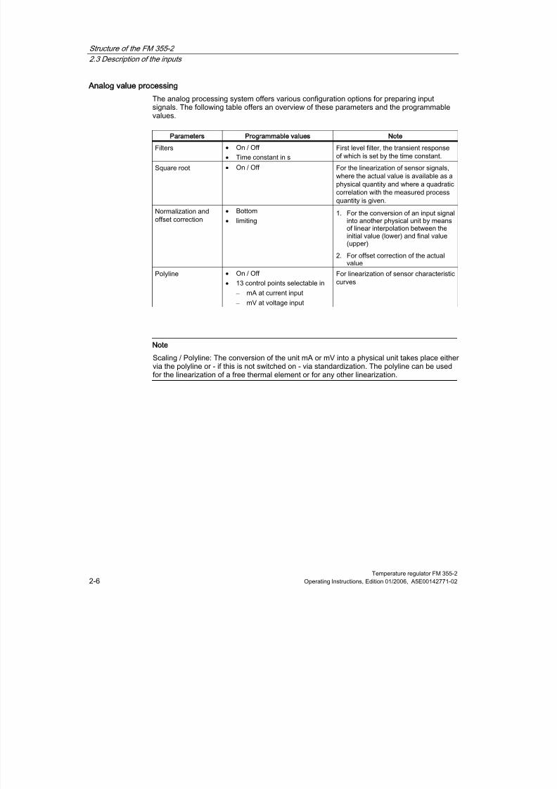
Analog value processing
The analog processing system offers various configuration options for preparing input
signals. The following table offers an overview of these parameters and the programmablevalues.
Parameters Programmable values Note
Filters • On / Off
•
Time constant in s
First level filter, the transient responseof which is set by the time constant.
Square root •
On / Off For the linearization of sensor signals,where the actual value is available as aphysical quantity and where a quadraticcorrelation with the measured processquantity is given.
Normalization and
offset correction
•
Bottom
•
limiting
1.
For the conversion of an input signal
into another physical unit by meansof linear interpolation between theinitial value (lower) and final value(upper)
2.
For offset correction of the actualvalue
Polyline •
On / Off
•
13 control points selectable in
– mA at current input
– mV at voltage input
For linearization of sensor characteristiccurves
Note
Scaling / Polyline: The conversion of the unit mA or mV into a physical unit takes place eithervia the polyline or - if this is not switched on - via standardization. The polyline can be usedfor the linearization of a free thermal element or for any other linearization.

8/11/2019 FM_355-2_e
http://slidepdf.com/reader/full/fm355-2e 27/244
Structure of the FM 355-2
2.4 Outputs of the FM 355-2
Temperature regulator FM 355-2Operating Instructions, Edition 01/2006, A5E00142771-02 2-7
2.3.2 Digital inputs
Operating modes
The digital inputs serve to switchover the operating modes of the individual controllerchannels.
The direction of control action for the digital inputs is configurable. The following settings arepossible for each of the 8 digital inputs:
• High active
• Low active or open
For the following operating modes you can set if the switching signal is only to come from theFB or additionally from a digital input:
•
Switchover to an external output value (manual operation)• Switchover to follow-up mode
• Switchover to safety setting
The following signals can also be assigned via digital inputs when using a step controller:
• Checkback: Control equipment on upper endstop
• Checkback: Control equipment on lower endstop
2.4
24
Outputs of the FM 355-2
Analog outputs for the FM 355-2 C
The following functions can be configured for each analog output of the FM 355-2 C:
• Signal Selection
• Signal type
Signal selection on the signal outputs
The signal selection function enables you to define which signal values will be given at therelevant analog outputs.
The following signal values can be assigned:
• the value zero
• the processed analog value of one of the 4 analog inputs
• The output value A of one of the 4 controller channels
• The output value B of one of the 4 controller channels

8/11/2019 FM_355-2_e
http://slidepdf.com/reader/full/fm355-2e 28/244
Structure of the FM 355-2
2.4 Outputs of the FM 355-2
Temperature regulator FM 355-22-8 Operating Instructions, Edition 01/2006, A5E00142771-02
Signal type on the analog outputs
You can determine the signal type for each of the analog outputs.
The following signal types can be assigned:• Current output 0 ... 20 mA
• Current output 4 ... 20 mA
• Voltage output 0 ... 10 V
• Current output -10 ... 10 V
Digital outputs for the FM 355-2 S
The digital outputs of the FM 355-2 S serve to provide control for integrating or non-integrating final control elements.
Table 2-1 Assignment and meaning of the digital outputs
Controller
channels
The digital outputs
assigned to the control
channel
Meaning of digital outputs
for step controllers
Assignment of digital
outputs for pulse
controllers
0 Open Output value A0 1 Close Output value B
2 Open Output value A1 3 Close Output value B
4 Open Output value A2
5 Close Output value B6 Open Output value A
3 7 Close Output value B
Open = open the control equipment
Close = close the control equipment

8/11/2019 FM_355-2_e
http://slidepdf.com/reader/full/fm355-2e 29/244
Structure of the FM 355-2
2.5 Operative mechanism of data storage on the FM 355-2
Temperature regulator FM 355-2Operating Instructions, Edition 01/2006, A5E00142771-02 2-9
2.5
25
Operative mechanism of data storage on the FM 355-2
Data flow during parameter assignment by means of configuring software
The illustration below shows the parameter data route from the configuring software to theFM 355-2.
Figure 2-4 Illustration parameterizing the FM 355-2 via the PG/PC and via the CPU

8/11/2019 FM_355-2_e
http://slidepdf.com/reader/full/fm355-2e 30/244
Structure of the FM 355-2
2.5 Operative mechanism of data storage on the FM 355-2
Temperature regulator FM 355-22-10 Operating Instructions, Edition 01/2006, A5E00142771-02
Parameter assignment
The FM 355-2 can be configured with the help of configuring software on a PG/PC. All
configuration data is stored in a system database (SDB).
Note
Please note that every time the CPU starts up (transition from STOP to RUN) theparameters in the FM 355-2 will be overwritten with the values from the system database.
Loading the parameters directly into the FM 355-2 (loading into module)
You can load the parameters directly into the FM 355-2 via the configuring software so that itis not necessary to repeatedly close the configuring software and set the CPU to STOP whiletesting parameters during the commissioning phase.
Loading directly into the FM 355-2 is sensible when testing parameters during thecommissioning phase.
If you change parameters via the configuring software and subsequently load the datadirectly into the FM 355-2, discontinuity can occur in the manipulated variable process. Werecommend the following procedure in order to ensure a controlled manipulated variableprocess:
1. Switch to manual operation (e.g. via the loop display).
2. Change the parameters.
3.
Load the data directly into the FM 355-2.4. Switch to automatic operation (e.g. via the loop display).
Save all parameters that were changed online.
The FM 355-2 offers the following options to change parameters online:
• by means of FB FMT_PID (controller parameters) and FMT_PAR (further parameters),
• with controller optimization,
• with the configuration software (Upload to module).
Please note that online parameters changed in this way will be overwritten by the
parameters in the CPU´s SDB when the CPU starts up or with a STOP-RUN transition.
In order to store changed parameters in the SDB of the CPU, please proceed as follows:
1. Load the parameters from the FM 355-2 withPLC > Upload to PG
in the configurationsoftware.
2. Save the parameters in the configuring software.
3. Leave the configuration software.
4. Save the project in HW Config with File > Save and compile.
5. Transfer the data to the CPU by means of PLC > Upload ...
If all the HW components are CiR-capable, you can also transfer the data in RUN.

8/11/2019 FM_355-2_e
http://slidepdf.com/reader/full/fm355-2e 31/244
Structure of the FM 355-2
2.5 Operative mechanism of data storage on the FM 355-2
Temperature regulator FM 355-2Operating Instructions, Edition 01/2006, A5E00142771-02 2-11
CiR: Configuration Change in RUN
The FM 355-2 is CiR-capable to a limited extent, i.e. when the configuration is changed whilethe CPU is in RUN, the majority of the FM 355-2 parameters can be changed without thishaving any effect on the output signals of the remaining channels. With a parameter changeof this nature, all the parameters of the FM 355-2 are saved in the SDBs of the CPU andthen transferred to the FM 355-2. Please refer to the "STEP 7 - Modifying the system duringoperation via CiR" electronic manual under STEP7 for more information on using CiR.
Note
With some embedded parameter changes, which refer to the entire module, brief interactionson all controller channels cannot be avoided. With "Configuration change in RUN" of the HWConfig or with "Download to module" from the configuration software, in this case the output
signals on the analog and digital outputs return to zero for 100 to 500 ms (depending on thenumber of active channels).
Module-specific parameters Configuration software
Line frequency: 50Hz / 60Hz Module parameters > General parameters
Unit temperature: Celsius / Fahrenheit Module parameters > General parameters
Digital input 1...8: 13 ...35V (H active) / 0 ... 4V or open(L active)
Module parameters > Direction of controlaction of the digital inputs
But this effect also occurs with the following channel-specific parameters.
Channel-specific parameters Configuration software
Reference junction temperature switch: Reference input / configured /internal compensation for thermocouple elements J, K and E
Analog input
Square root switch-on: on / off analog input > square root
Polyline switch-on: on / off Analog input > Polyline
Wire break monitoring switch-on: on / off Analog input > sensortype
Sensor type switch-on: Analog input will not be processed / power /voltage / PT100 / thermocouple element Analog input > sensortype
Controller type: Fixed setpoint or cascade controller / three-componentcontroller / ratio or mixed controller
Basic screen
Reaction in event of CPU failure: setpoint = last valid setpoint / setpoint= safety setpoint
Error signal > switchingsafety setpoint
Response to module startup: setpoint = last valid setpoint / setpoint =safety setpoint
Error signal > switchingsafety setpoint
Reaction in event of CPU failure: Manipulated variable = last validmanipulated variable / manipulated variable = safety setpoint
Controller output >switching safetymanipulated variable
8/11/2019 FM_355-2_e
http://slidepdf.com/reader/full/fm355-2e 32/244
Structure of the FM 355-2
2.5 Operative mechanism of data storage on the FM 355-2
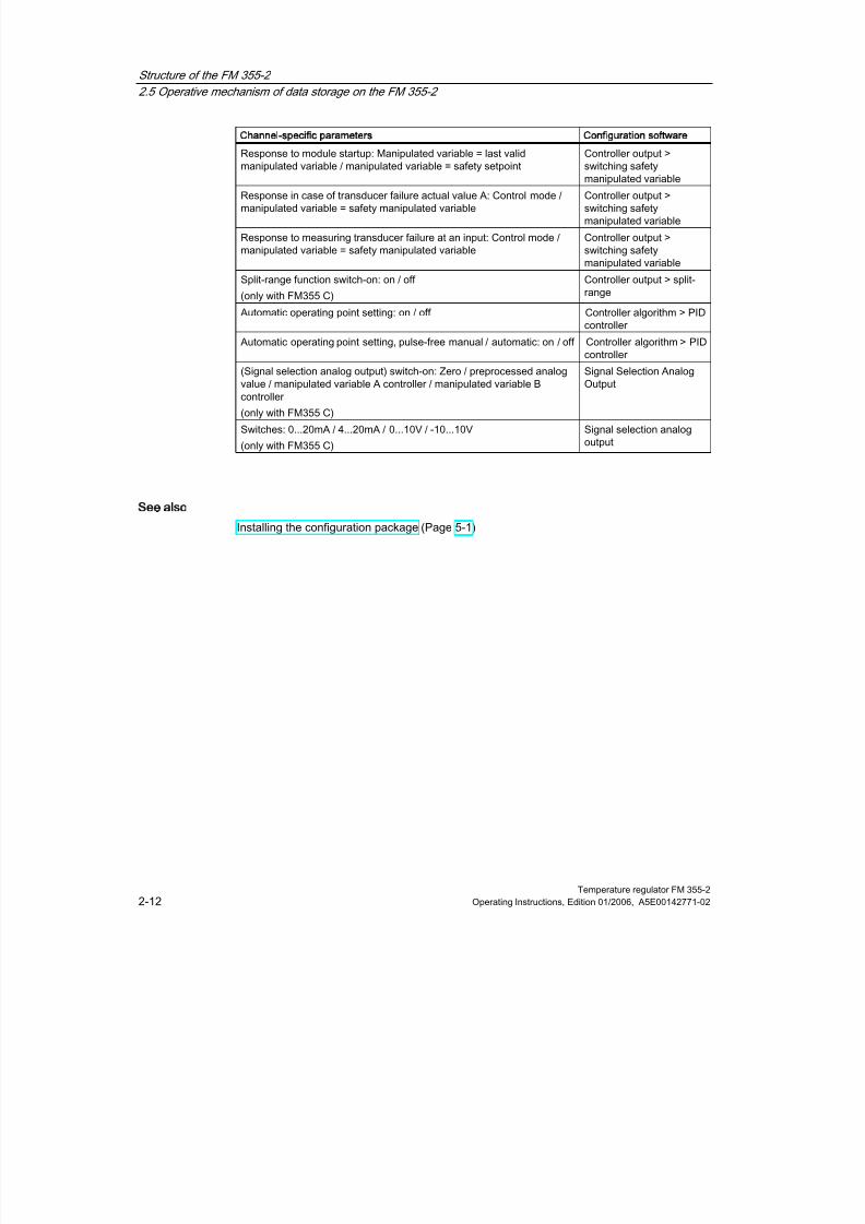
Temperature regulator FM 355-22-12 Operating Instructions, Edition 01/2006, A5E00142771-02
Channel-specific parameters Configuration software
Response to module startup: Manipulated variable = last valid
manipulated variable / manipulated variable = safety setpoint
Controller output >
switching safetymanipulated variable
Response in case of transducer failure actual value A: Control mode /manipulated variable = safety manipulated variable
Controller output >switching safetymanipulated variable
Response to measuring transducer failure at an input: Control mode /manipulated variable = safety manipulated variable
Controller output >switching safetymanipulated variable
Split-range function switch-on: on / off
(only with FM355 C)
Controller output > split-range
Automatic operating point setting: on / off Controller algorithm > PIDcontroller
Automatic operating point setting, pulse-free manual / automatic: on / off Controller algorithm > PIDcontroller
(Signal selection analog output) switch-on: Zero / preprocessed analogvalue / manipulated variable A controller / manipulated variable Bcontroller
(only with FM355 C)
Signal Selection AnalogOutput
Switches: 0...20mA / 4...20mA / 0...10V / -10...10V
(only with FM355 C)
Signal selection analogoutput
See also
Installing the configuration package (Page 5-1)

8/11/2019 FM_355-2_e
http://slidepdf.com/reader/full/fm355-2e 33/244
Structure of the FM 355-2
2.6 Characteristics of the FM 355-2
Temperature regulator FM 355-2Operating Instructions, Edition 01/2006, A5E00142771-02 2-13
2.6
26
Characteristics of the FM 355-2
Sequence of execution
The FM 355-2 processes the analog inputs and controller channels in a predeterminedorder. Each controller channel is processed immediately after the processing andpreparation of the identically numbered analog input. Subsequently the analog input with thenext highest number will be processed and so on. The reference junction is processed first.
Figure 2-5 FM 355-2 processing sequence

8/11/2019 FM_355-2_e
http://slidepdf.com/reader/full/fm355-2e 34/244
Structure of the FM 355-2
2.6 Characteristics of the FM 355-2
Temperature regulator FM 355-22-14 Operating Instructions, Edition 01/2006, A5E00142771-02
Scan time
The collective scan times for all of the FM 355-2 controllers result from the sum of theconversion times of the individual analog inputs. The conversion time for the reference junction is added to this, if it is used.
The conversion time for an analog input is always 100 ms.
If an analog input is not processed, the identically numbered controller will also not beprocessed (conversion time = 0).
There are no additional conversion times for the analog outputs. The analog manipulatedvariables of the FM 355-2 are output immediately after the corresponding manipulatedvariables have been calculated.
They amount to a minimum of 100ms (when only one analog input is processed) andmaximum 500 ms (if all 4 analog inputs and the reference junction are to be processed).
The figure below shows an example of the processing sequence of just three active analoginputs.
Figure 2-6 FM 355-2 processing sequence
The scan time for each controller from the above example is given as follows:tScan = 4 x 100 ms = 400 ms.

8/11/2019 FM_355-2_e
http://slidepdf.com/reader/full/fm355-2e 35/244
Structure of the FM 355-2
2.6 Characteristics of the FM 355-2
Temperature regulator FM 355-2Operating Instructions, Edition 01/2006, A5E00142771-02 2-15
Notes regarding FM 355-2 operation
The following notes apply to the operation of the FM 355-2:
•
The FM 355-2 controllers are end-stackable, i.e. they can set the manipulated variable ofa controller channel to the setpoint of another controller channel.
• The processing of a controller channel occurs immediately after the processing of theidentically numbered analog input.
Bearing in mind short dead times, should a controller use several analog inputs, youshould select the controller channel that corresponds to the highest analog input numberbeing used.
Example: a controller requires the signals from analog inputs 1, 2 and 3. The smallestdead time results from the selection of controller no. 3.
• If the setting "Analog input" on an analog input is set to not be processed, then theidentically numbered controller channel will also not be processed. This means that no
additional sampling time will be required for this analog input.• If the reference junction input is used, then the same conversion time is required as for an
analog input (100 ms).
• The scan time of a controller results from the sum of the conversion times of the activeanalog inputs plus the conversion time of the reference junction input.
Startup reaction of the FM 355-2
When the supply voltage is applied, the outputs remain on zero initially. The actual startupoperation begins when the FM 355-2 receives its parameter data (SDB) from the CPU.Depending on configuration, either a safety setting will be output or the FM 355-2 will be in
automatic mode. The FM 355-2 remains in startup operation until the FB FMT_PID is calledfor the first time.
Reactions in event of CPU failure
on failure or STOP of the CPU
• The setting "control output = safety setting" will be switched over to safety setting.
• The operating mode for the "standard operation" setting remains unchanged, and you canprogram the following responses in the "Switch safety settings" window.
– Last valid setpoint
If the setpoint selection has been set "by function block", then the setpoint will remainconstant at its last set value after a CPU failure. If the setpoint is given by an FMcontroller or from an analog input, then the setpoint changes correspondingly to thecalled value.
– Safety setpoint value
The FM regulates to the safety setpoint value.
8/11/2019 FM_355-2_e
http://slidepdf.com/reader/full/fm355-2e 36/244
Structure of the FM 355-2
2.6 Characteristics of the FM 355-2
Temperature regulator FM 355-22-16 Operating Instructions, Edition 01/2006, A5E00142771-02
Backup mode
If the CPU goes into STOP mode, fails, or the connection between the FM 355-2 and CPU is
interrupted, the FM 355-2 goes into backup mode and continues to control with theparameters that were valid at the time of the fault.
The following options are available, depending on configuration:
• Setpoint = safety setpoint value
• Standard operation with last valid setpoint
• Standard operation with safety setting
Safety mode is indicated by the yellow "Backup" LED.
Firmware update
Firmware updates can be downloaded onto the FM 355-2 operating system memory in orderto add extended functionality and fix errors. This function can be carried out underHW Config > PLC > Update Firmware
.
8/11/2019 FM_355-2_e
http://slidepdf.com/reader/full/fm355-2e 37/244
Temperature regulator FM 355-2Operating Instructions, Edition 01/2006, A5E00142771-02 3-1
Installing and removing the FM 355-2
3
3.1
31Preparing for Installation
Assign slots
The function module FM 355-2 occupies two slots. They can be installed in any of the slots 4to 11 in the same way as a signal module.
Configuring mechanical design
You will find information regarding what options are available for the mechanical designtogether with instructions on configuration in the manual entitled Automation system S7-300;Configuration, CPU data . The following section offers a few supplementary notes.
1. A maximum of 8 SMs or FMs per row (rack) are allowed.
2. The maximum number is restricted by the width of the module and the length of themounting rail. The FM 355-2 requires 80 mm installation width.
3.
The maximum is restricted by the sum current consumption of all modules to the right ofthe CPU from the 5V backplane bus supply. The typical current consumption of theFM 355-2 from the 5V backplane bus supply amounts to 50 mA.
4. The maximum number is restricted by the memory requirements of the software in theCPU, which is required for communication with the FM 355-2.
Determine mounting position
The rack should be mounted horizontally if possible. A restricted ambient temperatureapplies if the device is mounted vertically (max. 40 °C).
Determining start address
The start addresses must be entered in the instance DBs of the required FBs.
The start addresses for the FM 355-2 can be determined in accordance with the same rulesas the start addresses for analog modules.

8/11/2019 FM_355-2_e
http://slidepdf.com/reader/full/fm355-2e 38/244
Installing and removing the FM 355-2
3.1 Preparing for Installation
Temperature regulator FM 355-23-2 Operating Instructions, Edition 01/2006, A5E00142771-02
Fixed addressing
When using fixed addresses, the start address is dependent on the slot. Please refer to the
tables in the Automation system S7-300; Configuration, CPU data manual for informationpertaining to the start addresses for analog modules on various slots.
The fixed start address can also be calculated by means of the following equation:
Adr. = 256 + (rack number * 128) + (slot number - 4) * 16
Free addressing
Enter the start address for the module under STEP 7 in order to assign a free address.
Important safety rules
There are important rules that must be observed when integrating an S7-300 with an FM355-2 in a plant or system. These rules and regulations are to be found in the Automationsystem S7-300; Configuration, CPU data manual.
See also
Overview of the function blocks (Page 8-1)
8/11/2019 FM_355-2_e
http://slidepdf.com/reader/full/fm355-2e 39/244
Installing and removing the FM 355-2
3.2 FM 355-2 installation and removal
Temperature regulator FM 355-2Operating Instructions, Edition 01/2006, A5E00142771-02 3-3
3.2
32
FM 355-2 installation and removal
Protective measures
No special precautions (ESD directives) are required for the installation of the FM 355-2.
Tools required
A 4.5 mm screwdriver is required to install or remove the FM 355-2.
Procedure for installation
The following describes how the FM 355-2 is to be installed on the mounting rail. Additional
information pertaining to the installation of modules is to be found in the Automation systemS7-300; Configuration, CPU data manual.
1. Switch the CPU to STOP mode.
2. A bus connecter is supplied with the FM 355-2. Connect it to the bus connector on themodule to the left of the FM 355-2. (the bus connector is to be found on the back side, ifnecessary you may need to loosen the neighboring modules again).
3. Hang the FM 355-2 onto the rail and rotate it downwards.
4. Screw the FM 355-2 tight (torque approx. 0.8 to 1.1 Nm).
If additional modules are to be mounted to the right of the FM 355-2, first connect the busconnector for the next module to the right hand back wall bus connector of the FM 355-2.
Do not connect a bus connector should the FM 355-2 be the last module in the row.5. Label the FM 355-2 with its slot number. Use the numbering device included with the
CPU for this purpose.
Please refer to the information in the Automation system S7-300; Configuration, CPUdata manual for information regarding the fixed order that must be observed fornumbering and how the slot numbers are to be inserted.
6. Install the shield connection element.
8/11/2019 FM_355-2_e
http://slidepdf.com/reader/full/fm355-2e 40/244
Installing and removing the FM 355-2
3.2 FM 355-2 installation and removal
Temperature regulator FM 355-23-4 Operating Instructions, Edition 01/2006, A5E00142771-02
Procedure for installation
The following describes how to install the FM 355-2. Additional information pertaining to the
installation of modules is to be found in the Automation system S7-300; Configuration, CPUdata manual.
1. Switch off supply voltage L+ on the front connector.
2. Switch the CPU to STOP mode.
3. Open the front doors. If necessary, remove the labeling strips.
4. Unlock the front connector and remove it.
5. Undo the module fixing screws on the module.
6. Rotate the module out of the mounting rails and unhook it.
7. If necessary install the new module.
Further information
Additional information pertaining to the installation and removal of modules can be found inthe Automation system S7-300; Configuration, CPU data manual.

8/11/2019 FM_355-2_e
http://slidepdf.com/reader/full/fm355-2e 41/244
Temperature regulator FM 355-2Operating Instructions, Edition 01/2006, A5E00142771-02 4-1
Wiring the FM 355-2
4
4.1
41Terminal assignment on the front connector
4.1.1 FM 355-2 C front connector
Both 20-pole front connectors of the FM 355-2 C are used to connect the digital inputs, theanalog inputs and outputs, and the supply voltage for the module.
The illustration below shows the front side of the module, a front connector and the innerside of the front doors with the imprint of the terminal assignment.
Figure 4-1 FM 355-2 C front connector terminal assignment
① Front view of the module
② Front connectors
③ Terminal assignment of the left hand front connector
④ Terminal assignment of the right hand front connector

8/11/2019 FM_355-2_e
http://slidepdf.com/reader/full/fm355-2e 42/244
Wiring the FM 355-2
4.1 Terminal assignment on the front connector
Temperature regulator FM 355-24-2 Operating Instructions, Edition 01/2006, A5E00142771-02
Front connector assignment of the FM 355-2 C
Table 4-1 FM 355-2 C front connector terminal assignmentLeft front connector Right front connector
Connection Analog
input
Name Function Connection Analog
output
Name Function
1 - - - 1 - L+ 24 VDC supply voltage
2 IC+ Constant currentcable (pos)
2 - I0 Digital input
3 IC- Constant currentcable (neg)
3 - I1 Digital input
4 M+ Measuring cable (pos) 4 - I2 Digital input
5
0
M- Measuring cable
(neg)
5 - I3 Digital input
6 IC+ Constant currentcable (pos)
6 - I4 Digital input
7 IC- Constant currentcable (neg)
7 - I5 Digital input
8 M+ Measuring cable (pos) 8 - I6 Digital input
9
1
M- Measuring cable(neg)
9 - I7 Digital input
10 - COMP+
Reference junctioninput (pos)
10 - - -
11 - COMP-
Reference junctioninput (neg)
11 Q0 Analog output
12 IC+ Constant currentcable (pos)
12
0
MANA Reference point of measuringcircuit
13 IC- Constant currentcable (neg)
13 Q1 Analog output
14 M+ Measuring cable (pos) 141
MANA Reference point of measuringcircuit
15
2
M- Measuring cable(neg)
15 Q2 Analog output
16 IC+ Constant currentcable (pos)
162
MANA Reference point of measuringcircuit
17 IC- Constant current
cable (neg)
17 Q3 Analog output
18 M+ Measuring cable (pos) 183
MANA Reference point of measuringcircuit
19
3
M- Measuring cable(neg)
19 - - -
20 - MANA Reference point ofmeasuring circuit
20 - M Supply voltage ground24 VDC
8/11/2019 FM_355-2_e
http://slidepdf.com/reader/full/fm355-2e 43/244
Wiring the FM 355-2
4.1 Terminal assignment on the front connector
Temperature regulator FM 355-2Operating Instructions, Edition 01/2006, A5E00142771-02 4-3
Note
The MANA connections are to be connected low impedance to the central chassis ground. Ifyou supply the encoders with external voltage, you must also connect the ground of theexternal voltage source to the CPU ground.
4.1.2 FM 355-2 S front connector
View
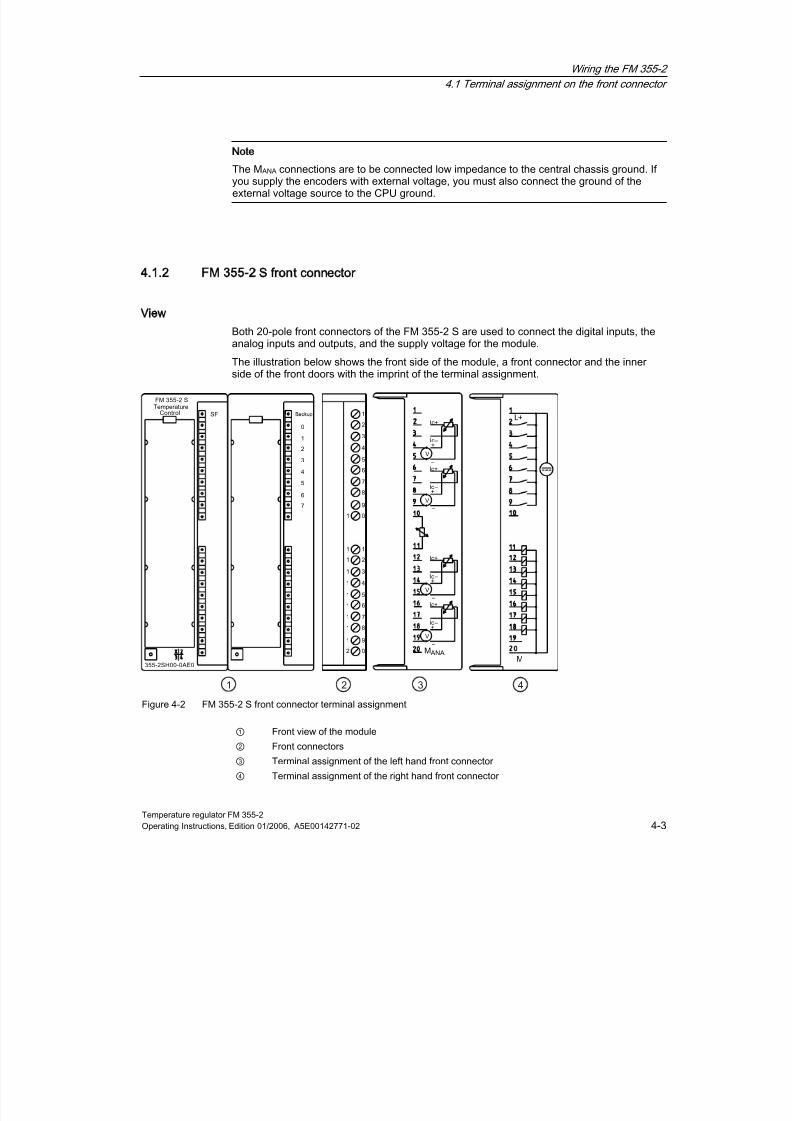
Both 20-pole front connectors of the FM 355-2 S are used to connect the digital inputs, theanalog inputs and outputs, and the supply voltage for the module.
The illustration below shows the front side of the module, a front connector and the innerside of the front doors with the imprint of the terminal assignment.
Figure 4-2 FM 355-2 S front connector terminal assignment
① Front view of the module
② Front connectors
③ Terminal assignment of the left hand front connector
④ Terminal assignment of the right hand front connector

8/11/2019 FM_355-2_e
http://slidepdf.com/reader/full/fm355-2e 44/244
Wiring the FM 355-2
4.1 Terminal assignment on the front connector
Temperature regulator FM 355-24-4 Operating Instructions, Edition 01/2006, A5E00142771-02
FM 355-2 S front connector assignment
Table 4-2 FM 355-2 S front connector terminal assignmentLeft front connector Right front connector
Connection Analog
input
Name Function Connection Controller
channel
Name Function
1 - - - 1 - L+ Supply voltage24 VDC
2 IC+ Constant currentcable (pos.)
2 - I0 Digital input
3 IC- Constant currentcable (neg.)
3 - I1 Digital input
4 M+ Measuring cable(pos)
4 - I2 Digital input
5
0
M- Measuring cable(neg)
5 - I3 Digital input
6 IC+ Constant currentcable (pos.)
6 - I4 Digital input
7 IC- Constant currentcable (neg.)
7 - I5 Digital input
8 M+ Measuring cable(pos)
8 - I6 Digital input
9
1
M- Measuring cable(neg)
9 - I7 Digital input
10 - COMP
+
Reference junction
input (pos.)
10 - - -
11
-
COMP-
reference junctioninput (neg)
11 Q0 Digital output
For step controller: Controloutput signal high
For pulse controller:Manipulated variable A
12 IC+ Constant currentcable (pos.)
12
0
Q1 Digital output
For step controller: Manipulatedvariable signal low
For pulse controller:Manipulated variable B
13 IC- Constant currentcable (neg.)
13 Q2 Digital output
For step controller: Controloutput signal High
For pulse controller:Manipulated variable A
14
2
M+ Measuring cable(pos)
14
1
Q3 Digital output
For step controller: Manipulatedvariable signal low
For pulse controller:Manipulated variable B

8/11/2019 FM_355-2_e
http://slidepdf.com/reader/full/fm355-2e 45/244
Wiring the FM 355-2
4.1 Terminal assignment on the front connector
Temperature regulator FM 355-2Operating Instructions, Edition 01/2006, A5E00142771-02 4-5
Left front connector Right front connector
Connection Analog
input
Name Function Connection Controller
channel
Name Function
15 M- Measuring cable(neg)
15 Q4 Digital output
For step controller: Controloutput signal High
For pulse controller:Manipulated variable A
16 IC+ Constant currentcable (pos.)
16
2
Q5 Digital output
For step controller: Manipulatedvariable signal low
For pulse controller:Manipulated variable B
17 IC- Constant current
cable (neg.)
17 Q6 Digital output
For step controller: Controloutput signal High
For pulse controller:Manipulated variable A
18 M+ Measuring cable(pos)
18
3
Q7 Digital output
For step controller: Manipulatedvariable signal low
For pulse controller:Manipulated variable B
19
3
M- Measuring cable(neg)
19 - - -
20 - MANA Reference point ofmeasuring circuit 20 - M Supply voltage ground 24 VDC
Note
The 20 MANA terminal is to be connected low impedance to the central chassis ground. If yousupply the encoders with external voltage, you must also connect the ground of the externalvoltage source to the CPU ground.

8/11/2019 FM_355-2_e
http://slidepdf.com/reader/full/fm355-2e 46/244
Wiring the FM 355-2
4.1 Terminal assignment on the front connector
Temperature regulator FM 355-24-6 Operating Instructions, Edition 01/2006, A5E00142771-02
4.1.3 Special notes regarding wiring
Supply voltage L+/M
A 24V direct current is to be connected to connectors L+ and M for the supply voltage to themodule and to supply the digital outputs.
An integrated diode protects the module against reverse polarity in the supply voltage.
Caution
Only an extra-low voltage of ≤ 60 VDC which is safely isolated from mains may be used forthe 24V supply. Safe isolation can be implemented by adhering to one of the followingspecifications:
•
VDE 0100 part 410 / HD 384-4-41 / IEC 364-4-41(functional low voltage with safeisolation)
• VDE 0805 / EN 60950 / IEC 950 (as SELV)
• VDE 0106 part 101
Note
The direct connection of inductors (e.g. from relays and contactors) is possible withoutexternal wiring. Where the SIMATIC output circuits can be switched off by additionalcontacts (e.g. relays), the inductors must be provided with additional overvoltage protectors(please see the following illustration for an example of overvoltage protection).

8/11/2019 FM_355-2_e
http://slidepdf.com/reader/full/fm355-2e 47/244
Wiring the FM 355-2
4.1 Terminal assignment on the front connector
Temperature regulator FM 355-2Operating Instructions, Edition 01/2006, A5E00142771-02 4-7
Example of overvoltage protection
The following figure illustrates an output circuit requiring additional overvoltage protection.
Figure 4-3 Relays in the output circuit
Circuit for coils operated with DC voltage
Coils operated with DC voltage are switched by means of diodes or Zener diodes.
+
-
+
-
Figure 4-4 Circuit for coils operated with DC voltage
Switching with diodes/Zener diodes
Diode/Zener diode circuits have the following characteristics:
• Opening surge voltage can be totally avoided. The Zener diodes have a higher switch-offvoltage capacity.
•
High switch-off delay (6 to 9 times higher than without protective circuit). The Zenerdiodes switch off faster than a diode circuit.
8/11/2019 FM_355-2_e
http://slidepdf.com/reader/full/fm355-2e 48/244
Wiring the FM 355-2
4.2 Wiring Front Connectors
Temperature regulator FM 355-24-8 Operating Instructions, Edition 01/2006, A5E00142771-02
4.2
42
Wiring Front Connectors
Rules for selecting cables
There are a number of rules that should be adhered to when selecting cables.
• The cables for the digital inputs I0 to I7 must be shielded when longer than 600m.
• Analog signal cables must be shielded.
• The shielding of the analog signal cables must be laid over the shield connection elementon the sensor as well as in the immediate vicinity of the module.
• Use flexible cables of 0.25 to 1.5 mm diameter 2.
• Conductor end sleeves are not required. If you use conductor end sleeves, then ensurethat only the type without insulating collar are used according to DIN 46228 type A, short
version.
Note
Unused analog inputs are to be shorted and connected to MANA.
Procedure
To wire the front connector, proceed as follows
1.
Move the front connector into the wiring position and open the front door.
2. Strip the conductors to a length of 6 mm.
3. Are you using conductor end sleeves?
If yes: Squeeze the conductor end sleeves to the conductors.
4. Feed the included cable strain relief into the front connector.
5. If you route the wires out downwards, start the wiring at the bottom. If this is not the case,start at the top. Screw also the unused connectors tight (torque 0.6 to 0.8 Nm).
6. Tighten the strain relief for the cable strain relief.
7. Replace the front connector into its operating position.
8.
Lay the conductor shield flat on the shield connection element or on the shield endelement.

8/11/2019 FM_355-2_e
http://slidepdf.com/reader/full/fm355-2e 49/244
Wiring the FM 355-2
4.2 Wiring Front Connectors
Temperature regulator FM 355-2Operating Instructions, Edition 01/2006, A5E00142771-02 4-9
9. Label the terminals with the labeling plate.
Figure 4-5 Connect the shielded conductors to the FM 355-2.

8/11/2019 FM_355-2_e
http://slidepdf.com/reader/full/fm355-2e 50/244
Wiring the FM 355-2
4.3 Module status after initial activation
Temperature regulator FM 355-24-10 Operating Instructions, Edition 01/2006, A5E00142771-02
4.3
43
Module status after initial activation
Characteristics
The following details characterize the state of the module after initial power activation, whenno data has yet been transferred (factory state):
• Analog inputs: No processing
• Analog outputs (FM 355-2 C): 0 mA
• Digital outputs (FM 355-2 S): 0 (disabled)
• No controller active
• Diagnostic interrupt disabled

8/11/2019 FM_355-2_e
http://slidepdf.com/reader/full/fm355-2e 51/244
Temperature regulator FM 355-2Operating Instructions, Edition 01/2006, A5E00142771-02 5-1
Installing the configuration package
5
Requirements
STEP 7 version 5.1 service pack 4 or better must be correctly installed on your PG/PC.
Delivery format
The software is provided on a CD-ROM together with the module.
Installation procedure
To install the software:
1. Place the CD into the CD-ROM drive of your PG/PC.
2. Select the CD drive from the dialog window and run the Setup.exe file to start theinstallation procedure.
3. Follow the on-screen step-by-step instructions of the installation program.
The installation procedure will install the following on your PG/PC:
•
Configuration software• Function blocks
• Program examples
• Online help
Program examples
The programming examples can be found in the STEP 7 catalog, in the "Examples"subsection under project zEn28_01_FMTemp.
Read the readme file
Any important up-to-date information regarding the supplied software will be in the readmefile, should the need arise. You can find this file on the CD under Start > Simatic > ProductNotes.

8/11/2019 FM_355-2_e
http://slidepdf.com/reader/full/fm355-2e 52/244
Installing the configuration package
Temperature regulator FM 355-25-2 Operating Instructions, Edition 01/2006, A5E00142771-02
Online help
The configuring software includes an online help function to support you in the parameter
assignment of the FM 355-2. The online help function can be called up in the following ways:• via the menu command Help > Help subjects...,
• by pressing the F1 key,
• by pressing the help button from within the individual configuration masks.
The online help function describes the parameterizing of modules in more detail than themanual.
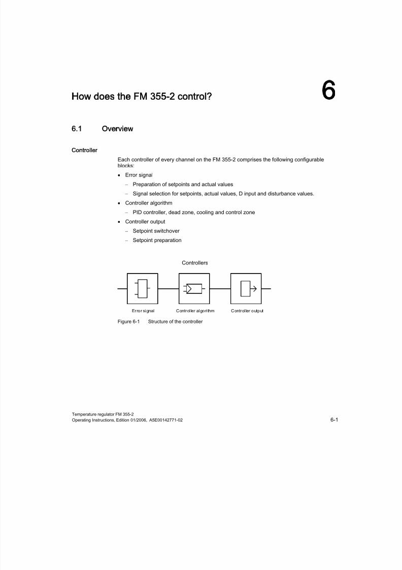
8/11/2019 FM_355-2_e
http://slidepdf.com/reader/full/fm355-2e 53/244
Temperature regulator FM 355-2Operating Instructions, Edition 01/2006, A5E00142771-02 6-1
How does the FM 355-2 control?
6
6.1
61Overview
Controller
Each controller of every channel on the FM 355-2 comprises the following configurableblocks:
• Error signal
– Preparation of setpoints and actual values
– Signal selection for setpoints, actual values, D input and disturbance values.
• Controller algorithm
– PID controller, dead zone, cooling and control zone
• Controller output
– Setpoint switchover
– Setpoint preparation
Figure 6-1 Structure of the controller
8/11/2019 FM_355-2_e
http://slidepdf.com/reader/full/fm355-2e 54/244
How does the FM 355-2 control?
6.1 Overview
Temperature regulator FM 355-26-2 Operating Instructions, Edition 01/2006, A5E00142771-02
Controller structures and controller types
For each controller channel on the FM 355-2 C or FM 355-2 S you can create various
controller structures:• Fixed value or cascade controller
• Three-component controller
• Ratio controller or composition controller
The FM 355-2 S enables you to choose between the following controller types:
• Step controller without position feedback
• Step control with position feedback
• Pulse controller
Binary setpoint output signal
All three FM 355-2 S controller types work with binary setpoint output signals.
The step controllers are used for integrating control elements (e.g. servo motors). Twoversions are configurable: with or without analog position feedback. An analog positionfeedback is often not available. They are not to be confused with the endstop signals (binaryposition feedbacks: upper or lower endstop of control element reached). These are generallyavailable and are to be configured in the controller output block by clicking pulse former.
The pulse controller is used for creating pulse width modulated control signals. Theconversion in a binary output signal occurs in such a way that the ratio pulse length to theparameterized period equals the setpoint on the assigned digital output (see Split-range /pulse former button). There are two possibilities for the pulse controller:
•
Two-position controller: works with setpoint A and requires only one digital output (e.g.pure filament rheostat)
• Three-position controller: works with setpoints A and B and requires two digital outputs(e.g. combined heating and refrigeration control).
See also
Introduction (Page 6-3)
8/11/2019 FM_355-2_e
http://slidepdf.com/reader/full/fm355-2e 55/244
How does the FM 355-2 control?
6.2 Error signal
Temperature regulator FM 355-2Operating Instructions, Edition 01/2006, A5E00142771-02 6-3
6.2
62
Error signal
6.2.1 Introduction
Principle
The same basic control deviation structures underlie all of the implemented controllerstructures in the FM 355-2 C and FM 355-2 S.
The effective setpoints and effective actual values are calculated from the setpoints andactual values by means of appropriate processing. The control deviation is achieved bysubtracting the effective actual value from the effective setpoint that is supplied to thecontroller.
You can assign a signal selection for the setpoints and actual values. This means the FM355-2 has universal application possibilities.
The control deviation structures differ, dependent on the selected controller structure.
See also
Fixed value or cascade controller (Page 6-4)
Three-component controller (Page 6-5)
Ratio controller or composition controller (Page 6-6)
Sample application for FM 355-2 C (closed-loop controller) (Page 13-2)
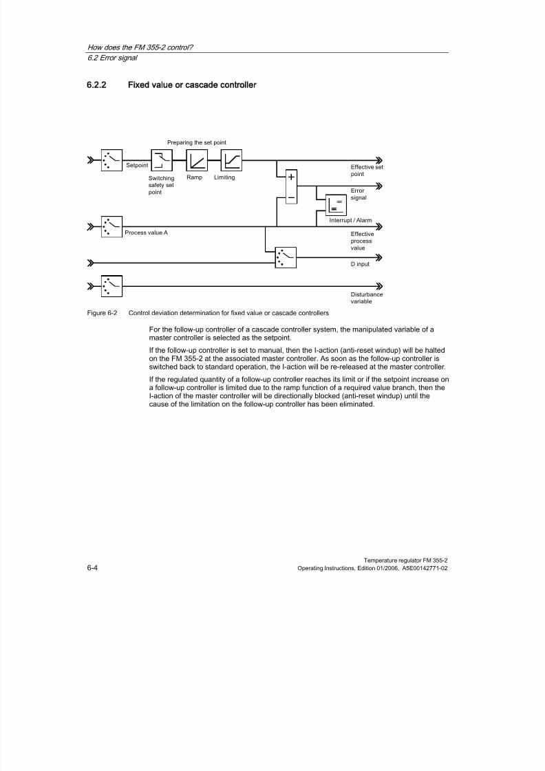
8/11/2019 FM_355-2_e
http://slidepdf.com/reader/full/fm355-2e 56/244
How does the FM 355-2 control?
6.2 Error signal
Temperature regulator FM 355-26-4 Operating Instructions, Edition 01/2006, A5E00142771-02
6.2.2 Fixed value or cascade controller
Figure 6-2 Control deviation determination for fixed value or cascade controllers
For the follow-up controller of a cascade controller system, the manipulated variable of amaster controller is selected as the setpoint.
If the follow-up controller is set to manual, then the I-action (anti-reset windup) will be haltedon the FM 355-2 at the associated master controller. As soon as the follow-up controller isswitched back to standard operation, the I-action will be re-released at the master controller.
If the regulated quantity of a follow-up controller reaches its limit or if the setpoint increase ona follow-up controller is limited due to the ramp function of a required value branch, then theI-action of the master controller will be directionally blocked (anti-reset windup) until thecause of the limitation on the follow-up controller has been eliminated.

8/11/2019 FM_355-2_e
http://slidepdf.com/reader/full/fm355-2e 57/244
How does the FM 355-2 control?
6.2 Error signal
Temperature regulator FM 355-2Operating Instructions, Edition 01/2006, A5E00142771-02 6-5
6.2.3 Three-component controller
The three-component controller is required for the realization of a total quantity control forcomposition controllers.
The total quantity PV is calculated by means of its inputs "actual value A, actual value B andactual value C".
Figure 6-3 Control deviation determination for three-component controllers
See also
Example of a blending control circuit (Page 13-19)

8/11/2019 FM_355-2_e
http://slidepdf.com/reader/full/fm355-2e 58/244
How does the FM 355-2 control?
6.2 Error signal
Temperature regulator FM 355-26-6 Operating Instructions, Edition 01/2006, A5E00142771-02
6.2.4 Ratio controller or composition controller
Ratio or composition controllers are always follow-up controllers. The associated mastercontroller to a ratio controller is a constant value controller.
Figure 6-4 Control deviation determination for ratio or composition controllers
The actual value of the master controller is selected as actual value D. The ratio factor isgiven by means of the reference input. If a controller output is called as ratio factor FAC,then the setpoint will be converted (standardized) with the help of an upper and lower barrierfrom "0 .. 100%" by means of the value range "lower barrier ... upper barrier".
The associated master controller to a composition controller is a three-component controller.
The regulated quantity of the master controller is switched via the input actual value D. Theproportional factor is given via the controller's reference input.
The regulated quantity LMN of the total quantity control is given within the range of values0% to 100%. From the follow-up controller, these quantities are converted at actual valueinput D into the actual value A (the value range of actual value A corresponds to thestandardized values "upper" and "lower" of the selected analog input).
If the regulated quantity of a follow-up controller reaches its limit or if the setpoint increase ona follow-up controller is limited due to the ramp function of a required value branch, then theI-action of the master controller will be directionally blocked (anti-reset windup) until thecause of the limitation on the follow-up controller has been eliminated.

8/11/2019 FM_355-2_e
http://slidepdf.com/reader/full/fm355-2e 59/244
How does the FM 355-2 control?
6.2 Error signal
Temperature regulator FM 355-2Operating Instructions, Edition 01/2006, A5E00142771-02 6-7
See also
Example of a ratio control (Page 13-18)
Example of a blending control circuit (Page 13-19)

8/11/2019 FM_355-2_e
http://slidepdf.com/reader/full/fm355-2e 60/244
How does the FM 355-2 control?
6.2 Error signal
Temperature regulator FM 355-26-8 Operating Instructions, Edition 01/2006, A5E00142771-02
6.2.5 Signal selection for setpoints, actual values, D input and disturbance values.
You can select from various signal sources for the setpoint, the actual value, the value of theD input (differentiating input) and the disturbance variable of each controller channel. Thefollowing table offers an overview of the signal selection options.
Table 6-1 Signal selection for setpoints, actual values, D input and disturbance variables.
Affected values Selectable signal sources
Setpoint •
A given value from the user program via the function module
•
The processed analog value of an analog input
•
The setpoint (LNM, LNM_A or LNM_B) of another controller channel
(when cascading controllers)Actual values A, B andC
•
Zero
•
The processed analog value of an analog input
(the actual values B and C can be additionally evaluated by factors)
Actual value D • Zero
•
The processed analog value of an analog input
•
Setpoint of another controller channel
Value for D input (onlyrelevant for PD or PIDcontrollers)
•
The control deviation after the dead zone of the controller channel
•
The processed analog value of an analog input
•
The negated effective actual value of the controller channel
Disturbance variable •
Zero
•
The processed analog value of an analog input

8/11/2019 FM_355-2_e
http://slidepdf.com/reader/full/fm355-2e 61/244
How does the FM 355-2 control?
6.2 Error signal
Temperature regulator FM 355-2Operating Instructions, Edition 01/2006, A5E00142771-02 6-9
6.2.6 Preparation actual value
Parameterizing possibilities
The preparation of a setpoint to an effective actual value can be influenced by means of thefollowing configuration options:
• Switch safety setpoint
Here you can set:
– a safety setpoint
– the reaction of the FM 355-2 in the event of CPU failure
The options for FM 355-2 reactions are:
Setpoint = last valid setpoint
Setpoint = safety setpoint
• Ramp
You can limit the setpoint rate of change by means of the selection of a ramp up timefrom the physical start to the final value.
• Limiting / standardizing
If the setpoint of a function block is given or a processed analog value of an analog inputexists, the setpoint will be limited to a configurable upper and lower barrier.
When a controller output has been selected as a setpoint for a ratio controller, then thisvalue acts as the factor for the multiplication of setpoint D. In this case the setpoint that isgiven as a percentage on the input can be adjusted with the help of the upper and lower
barrier, via the Limit/Standardize button.
When a fixed value or cascade controller is used as set value for the setpoint of anothercontroller, then this can be standardized to a physical value with the help of astandardization constant of the called actual value channel.
• Multiplication
For the ratio type of controller, the actual value A is used as the controlled variable andactual value D as the ration quantity. The setpoint input serves as ratio factor. It isprocessed to an effective setpoint by multiplication of the actual value D and the additionof a configurable offset. If actual value D is switched off, then the offset will just be addedto the setpoint.
6.2.7 Preparation actual value
Effective actual value
The effective actual value is identical to actual value A for control structures on fixed value orcascade controllers and ratio controllers.
The effective actual value for the control structures on three-component controllers is formedby the sum of the 3 actual values A, B and C plus the configurable offset. The actual valuesB and C can be additionally evaluated by factors.

8/11/2019 FM_355-2_e
http://slidepdf.com/reader/full/fm355-2e 62/244
How does the FM 355-2 control?
6.3 Controller algorithm
Temperature regulator FM 355-26-10 Operating Instructions, Edition 01/2006, A5E00142771-02
6.2.8 Interrupt
Limit value monitoring
A limit value monitoring system is realized in the FM 355-2. This enables,
• either the control deviation
• or the effective actual value
to be monitored within an upper and lower warning limit and within an upper and lower alarmlimit. Additionally, a hysteresis can be created for these limits.
Figure 6-5 Hysteresis for warning and alarm limits
6.3
63
Controller algorithm
Components of the controller algorithm
Continuous-action controllers (FM 355-2 C) and pulse controllers (FM 355-2 S) have thesame controller algorithm structure. The cooling and control zone buttons cannot be selectedon the step controller (FM 355-2 S).
Figure 6-6 Control algorithm block diagram for continuous-action controllers and pulse controllers

8/11/2019 FM_355-2_e
http://slidepdf.com/reader/full/fm355-2e 63/244
How does the FM 355-2 control?
6.4 Description of the control algorithm
Temperature regulator FM 355-2Operating Instructions, Edition 01/2006, A5E00142771-02 6-11
6.4
64
Description of the control algorithm
6.4.1 Dead zone
Purpose of dead zones
A deadzone is interconnected upstream of the PID controller. The deadzone surprises thenoise component in the control deviation signal, which can occur if a high-frequencydisturbance signal interferes with the controller or reference input variable. This preventsundesirable oscillation in the controller output.
Dead band width
The deadzone range is configurable. If the control deviation lies within the configureddeadzone range, the value 0 (control deviation = 0) will be given on the output. Only if theinput variable moves outside of the sensitivity range, will the output value change by thesame value as the input variable.
This results in a distortion of the transferred signal, also outside of the deadzone. This ishowever an acceptable trade-off in that it prevents jumps at the deadzone limits. Thedistortion corresponds to the value of the deadzone range and can therefore be easilycontrolled.
Figure 6-7 Dead zone

8/11/2019 FM_355-2_e
http://slidepdf.com/reader/full/fm355-2e 64/244
How does the FM 355-2 control?
6.4 Description of the control algorithm
Temperature regulator FM 355-26-12 Operating Instructions, Edition 01/2006, A5E00142771-02
6.4.2 PID control algorithm
Controller algorithm: PID in parallel structure
During the cycle of the configured sampling time the controller’s manipulated variable iscalculated from the error signal of the PID position algorithm. The algorithm is designed as apurely parallel structure. The proportional, integral and differential components can beswitched off individually. For the integral and derivative components this is done by settingthe respective parameter TI or TD to zero.
Figure 6-8 Control algorithm of the FM 355-2 (parallel structure)
Feedforward control
:
A disturbance variable DISV can be additionally applied to the controller’s output signal.
Attenuation of the P action in event of setpoint changes
You can avoid actual value overshoot or an excessive amplitude of the manipulated variablewith attenuation of the P action via the parameter “Proportional factor at setpoint change”(PFAC_SP). Using PFAC_SP you can select continuously between 0.0 and 1.0 to decide theeffect of the P action when the setpoint changes:
• PFAC_SP=1.0: P action has full effect if setpoint changes
• PFAC_SP=0.0: P action has no effect if setpoint changes
Peculiarities of the step controller
A PFAC_SP value < 1.0 can reduce overshoot if the motor actuating time MTR_TM is small
compared to the equivalent time constant TA and if the ratio is TU/TA < 0.2. ShouldMTR_TM reach 20 % of TA, only a slight improvement can be achieved.

8/11/2019 FM_355-2_e
http://slidepdf.com/reader/full/fm355-2e 65/244
How does the FM 355-2 control?
6.4 Description of the control algorithm
Temperature regulator FM 355-2Operating Instructions, Edition 01/2006, A5E00142771-02 6-13
D action in feedback path
When the setpoint changes, you can avoid pulse-shaped D action of the manipulated
variable by moving the D action into the feedback path.In this structure only the negative setpoint (Factor = -1) is fed forward to the D action. Thederivative component is switched to the feedback path via “Controller D-input” switch, byselecting the inverted effective actual value from the “control deviation” window as inputsignal. You can also select the input variable of the derivative component via parameterD_EL_SEL of function block FMT_PID (see chapter on the function module FB 52FMT_PID").
Note
If you move the D action to the feedback path, you should also reduce the value ofPFAC_SP, otherwise you would increase overshoot of the actual value.
Figure 6-9 Control algorithm with D action in the feedback path
Inversion of the controller effect
You can enable controller inversion, that is, conversion from
• rising error signal = rising manipulated variable
to
• rising error signal = rising manipulated variable
by setting a negative proportional action coefficient (GAIN). The polarity sign of theparameter value determines the controller’s direction of action.

8/11/2019 FM_355-2_e
http://slidepdf.com/reader/full/fm355-2e 66/244
How does the FM 355-2 control?
6.4 Description of the control algorithm
Temperature regulator FM 355-26-14 Operating Instructions, Edition 01/2006, A5E00142771-02
Proportional control
The integral and derivative action is switched off in a proportional controller. That is, the
manipulated variable is also “0” when the error signal ER = 0. When the operating point ≠0,in other words, a numeric value for the manipulated variable with error signal = 0, thefollowing is possible via the operating point:
• Automatic operating point: When you switch from manual to auto mode, the controllerautomatically sets the operating point to the value of the current (manual) manipulatedvariable.
• Manual operating point: You can configure the operating point parameters.
• Example: Operating point AP = 5% results in a manipulated variable of 5%, with errorsignal ER = 0.
Figure 6-10 Proportional controller with operating point setting via integral component
Figure 6-11 Step response of the proportional controller

8/11/2019 FM_355-2_e
http://slidepdf.com/reader/full/fm355-2e 67/244
How does the FM 355-2 control?
6.4 Description of the control algorithm
Temperature regulator FM 355-2Operating Instructions, Edition 01/2006, A5E00142771-02 6-15
PI control
The D component is disabled in a PI controller (TD=0.0). A PI controller adjusts the output
variable via the integral component until the error signal ER = 0. However, this only applies ifthe output variable does not exceed the correcting range. The integrator maintains the valueit has at the point where the limits of the manipulated value are exceeded (Anti-Reset-Windup).
Figure 6-12 Step response of the PI controller
Pulse-free manual/auto mode changeover
If you have selected “Pulse-free manual/auto mode changeover” (not with step controller),the integrator is corrected manually so that the manipulated variable does not perform a stepacross the proportional and derivative component as a result of this manual/auto modechangeover. The I action error signal compensation rate is slow. When you switch frommanual to auto mode and if pulse-free manual/auto mode changeover is not selected, themanipulated variable will perform a step that follows the current error signal. This way anerror signal is quickly corrected.
Note
A step controller is always subject to pulse action at the changeover from manual toautomatic mode. The existing error signal and GAIN leads to a jump in the internalmanipulated variable. The integral effect of the actuator, however, results in a ramp-shapedexcitation of the process.
I action control
You can switch off the proportional component of a PI action to obtain a purely integralcontrol. This is also possible via the parameter P_SEL of function block FMT_PID.

8/11/2019 FM_355-2_e
http://slidepdf.com/reader/full/fm355-2e 68/244
How does the FM 355-2 control?
6.4 Description of the control algorithm
Temperature regulator FM 355-26-16 Operating Instructions, Edition 01/2006, A5E00142771-02
PD control
The I action is disabled in a PD controller (TI=0.0). That is, the output signal = 0 when the
error signal ER = 0. When the operating point ≠0, in other words, a numeric value for themanipulated variable with error signal = 0, the following is possible via the operating point:
• Automatic operating point: When you switch from manual to auto mode, the controllerautomatically sets the operating point to the value of the current (manual) manipulatedvariable.
• Manual operating point: You can configure the operating point parameters.
The PD controller generates a proportional component of the input variable ER(t) for theoutput signal and then adds the D action that is generated by differentiation of ER(t). Thetime response (strength of the D action or control area ) is determined by the derivativeaction time TD (rate time).
For signal smoothing and interference suppression, the D action is realized with a delay
circuit of the first order.The higher the derivative factor D_F,
• the smaller is the effective time constant TD/D_F of the delay and
• the higher is the maximum initial manipulated variable
• the better is the control action and
• the higher, however, is noise sensitivity.
D_F is limited to the value range 5.0 through 10.0.
Figure 6-13 Step response of the PD controller

8/11/2019 FM_355-2_e
http://slidepdf.com/reader/full/fm355-2e 69/244
How does the FM 355-2 control?
6.4 Description of the control algorithm
Temperature regulator FM 355-2Operating Instructions, Edition 01/2006, A5E00142771-02 6-17
PID control
The P, I and D action is enabled in a proportional controller. A PID controller adjusts the
output variable via the integral component until the error signal ER = 0. However, this onlyapplies if the output variable does not exceed the correcting range. The integrator maintainsthe value it has at the point where the limits of the manipulated value are exceeded (Anti-Reset-Windup).
The PID controller generates a proportional component of the input variable ER(t) for theoutput signal and then adds the derivative action that is generated by differentiation andintegration of ER(t). The time response is determined by the derivative action time TD (ratetime) and the integration time TI (reset time).
For signal smoothing and interference suppression, the D action is realized with a delaycircuit of the first order.
The higher the derivative factor D_F,
•
the smaller is the effective time constant TD/D_F of the delay and• the higher is the maximum initial manipulated variable
• the better is the control action and
• the higher, however, is noise sensitivity.
• D_F is limited to the value range 5.0 through 10.0.
Figure 6-14 Step response of the PID controller
Implementation, configuration and tuning of the PID controller
A problem not to be underestimated is the manual configuration of PI / PID controllerparameters, that is, to find their “correct” settings. The quality of this parameter assignmentis decisive for the intended use of a PID control and demands either substantial practicalexperience or special know-how, or time-consuming effort.
The self-tuning functions of the module can be used to assign the controller parameters. Youcan start this self-tuning function in your parameter assignment application, at the OP ordirectly via FB FMT_PID. After the identification of a process, the process model isdetermined and then used to calculate optimal controller parameter settings.

8/11/2019 FM_355-2_e
http://slidepdf.com/reader/full/fm355-2e 70/244
How does the FM 355-2 control?
6.4 Description of the control algorithm
Temperature regulator FM 355-26-18 Operating Instructions, Edition 01/2006, A5E00142771-02
See also
Overview (Page 7-1)
6.4.3 Cooling
Controller gain in cooling mode
The different control loop gain of closed-loop controllers and pulse controllers is taken intoaccount via the ratio factor RATIOFAC:
If RATIOFAC <> 0.0, a manipulated value < 0.0 is multiplied by RATIOFAC.
The effective controller gain in the cooling range is therefore RATIOFAC*GAIN.
Note
You require manipulated variable B when you switch on split-range mode for cooling/heating.Therefore, you have to configure the limit of the lower manipulated value LMN_LLM (e.g. -100.0 %) and the split-range function accordingly.

8/11/2019 FM_355-2_e
http://slidepdf.com/reader/full/fm355-2e 71/244
How does the FM 355-2 control?
6.4 Description of the control algorithm
Temperature regulator FM 355-2Operating Instructions, Edition 01/2006, A5E00142771-02 6-19
6.4.4 Control zone
Function
If CONZ_ON = TRUE, the closed-loop controller or pulse controller operates with a controlzone. This means that the controller is operated according to the following algorithm:
• LMN_HLM is output (manual control) if the error signal is higher than the positive controlzone CON_ZONE.
• The value LMN_LLM is output as manipulated variable (manual control) if the error signalis smaller than (-CON_ZONE) or (-CON_ZONE/RATIOFAC if RATIOFAC<>0.0) (negativecontrol zone).
• If the error signal stays within the control zone, the value calculated by the PID algorithmis fed forward without changes (automatic control).
• A hysteresis of 20% of the control zone is maintained for the transition between manualand automatic control.
Note
Before you switch on the control zone manually, make sure the setting of the control zoneband is not too small. If the control zone band is too small, oscillations will occur in themanipulated variable and actual value.
Should split-range mode for cooling/heating not be enabled, the ratio factor is to beRATIOFAC=0.0 A RATIOFAC unintentionally set to <> 0.0, may lead to the followingproblems:
• After tuning or with LOAD_PID, the calculated value of CON_ZONE is increased by 50%.
• The negative control zone (effective with negative step) is additionally divided by thevalue RATIOFAC.
Advantages of the control zone
When the actual value enters the control zone, the D action causes a very rapid reduction ofthe manipulated variable. This means that the control zone only makes sense if derivativeaction is enabled. Without a control zone, basically only the reducing P action would reducethe manipulated variable. The control zone leads to a faster settling time without overshootand subsequent undershoot, if there is a great distance between the output minimum ormaximum manipulated variable and the manipulated variable required for steady state of thenew operating point.

8/11/2019 FM_355-2_e
http://slidepdf.com/reader/full/fm355-2e 72/244
How does the FM 355-2 control?
6.5 Controller output
Temperature regulator FM 355-26-20 Operating Instructions, Edition 01/2006, A5E00142771-02
6.5
65
Controller output
6.5.1 Controller output functions
Parameter Assignment
Table 6-2 Controller output functions and possible configurations
Controller output functions Adjustable parameters
Enabling an external manipulatedvalue (manual mode)
Switching between the external and the effective manipulated value (automaticmode) from the controller can be done in one of the following ways:
•
via a function block•
via logical OR link of a digital value from a function block and a digital input.
Correction input The following alternative settings are available:
•
The value at the correction input = zero
•
The value at the correction input is the pre-processed analog value of an analoginput
Switch correction You can toggle between the manipulated value and the compensation input asfollows:
•
via a function block
•
via logical OR link of a digital value from a function block and a digital input.
Position feedback input (step-action controllers only)
The following alternative settings are available:
•
The value at the position feedback input = 0•
The value at the position feedback input is the pre-processed analog value of ananalog input
Switch safety setpoint value •
Determination of a safety setpoint value
•
Response of FM 355-2 during startup:
– FM 355-2 goes into auto mode,
– the safety setpoint value is output as setpoint value.
•
The changeover to safety setpoint value can be achieved by means of
– a function block
– via logical OR link of a digital value from a function block and a digital input.
•
Reaction in event of CPU failure:
– With the setting “closed-loop control” the controller mode remains unchanged.
– The setting "setpoint value = safety setpoint value" will be switched over to thesafety setpoint value.
•
Reaction to measuring transducer fault of actual value A:
– With the setting "closed-loop control" the controller mode remains unchanged.
– The setting "control output = safety setting" will be switched over to safetysetting.
•
Reaction to measuring transducer fault on an analog input:
– With the setting "closed-loop control" the controller mode remains unchanged.
– The setting "control output = safety setting" will be switched over to safetysetting.
Manipulated value limiting High and low limit
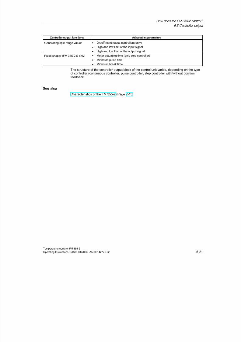
8/11/2019 FM_355-2_e
http://slidepdf.com/reader/full/fm355-2e 73/244
How does the FM 355-2 control?
6.5 Controller output
Temperature regulator FM 355-2Operating Instructions, Edition 01/2006, A5E00142771-02 6-21
Controller output functions Adjustable parameters
Generating split-range values •
On/off (continuous controllers only)
•
High and low limit of the input signal•
High and low limit of the output signal
Pulse shaper (FM 355-2 S only) • Motor actuating time (only step controller)
• Minimum pulse time
•
Minimum break time
The structure of the controller output block of the control unit varies, depending on the typeof controller (continuous controller, pulse controller, step controller with/without positionfeedback.
See also
Characteristics of the FM 355-2 (Page 2-13)

8/11/2019 FM_355-2_e
http://slidepdf.com/reader/full/fm355-2e 74/244
How does the FM 355-2 control?
6.5 Controller output
Temperature regulator FM 355-26-22 Operating Instructions, Edition 01/2006, A5E00142771-02
6.5.2 Controller output for continuous controller
Figure 6-15 Controller output of the continuous controller (FM 355-2 C)
Split-range
With the help of the split-range function you can excite two control valves with only onemanipulated variable. The split-range function uses the manipulated value LMN as inputsignal to generate the two output signals manipulated value A and manipulated value B.
Figure 6-16 Manipulated value A of the split-range function
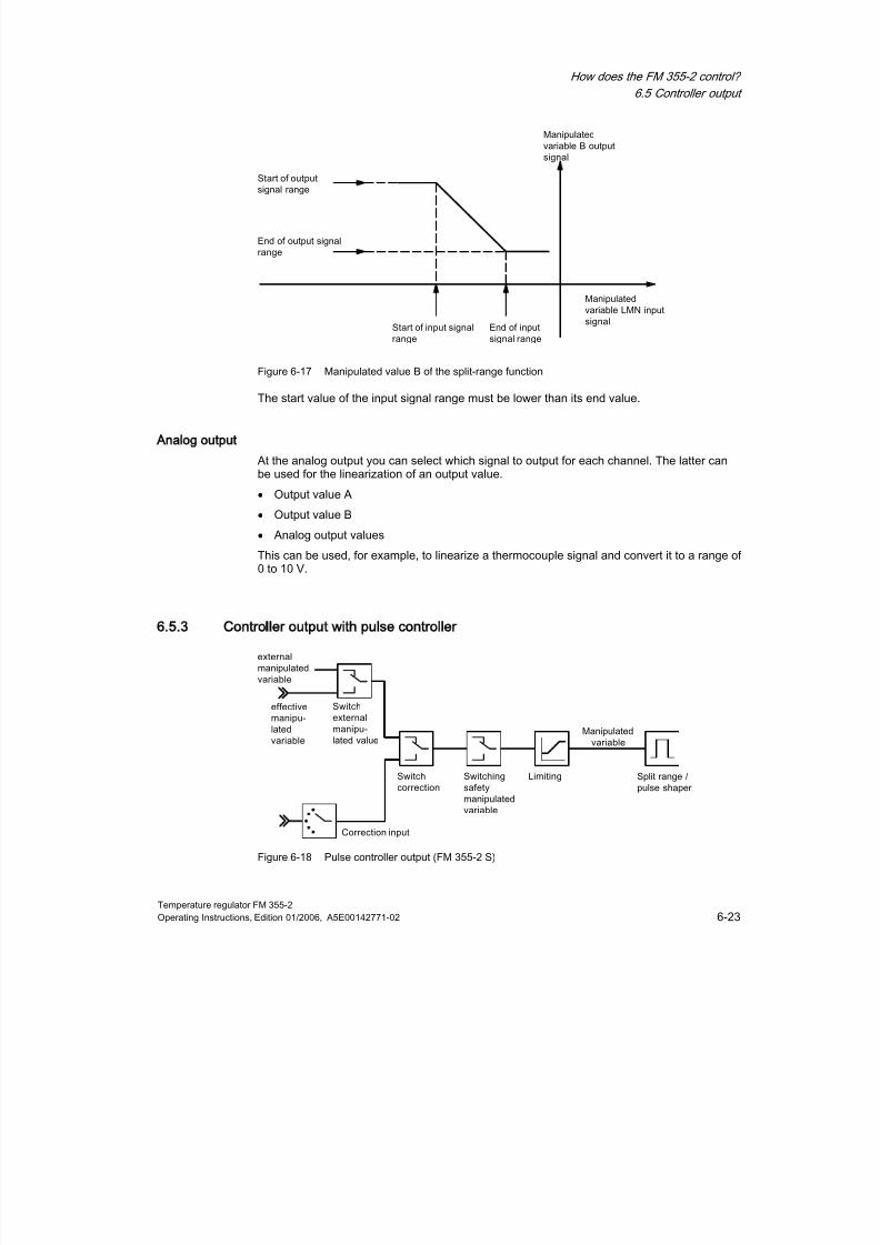
8/11/2019 FM_355-2_e
http://slidepdf.com/reader/full/fm355-2e 75/244
How does the FM 355-2 control?
6.5 Controller output
Temperature regulator FM 355-2Operating Instructions, Edition 01/2006, A5E00142771-02 6-23
Figure 6-17 Manipulated value B of the split-range function
The start value of the input signal range must be lower than its end value.
Analog output
At the analog output you can select which signal to output for each channel. The latter canbe used for the linearization of an output value.
• Output value A
• Output value B
• Analog output values
This can be used, for example, to linearize a thermocouple signal and convert it to a range of0 to 10 V.
6.5.3 Controller output with pulse controller
Figure 6-18 Pulse controller output (FM 355-2 S)

8/11/2019 FM_355-2_e
http://slidepdf.com/reader/full/fm355-2e 76/244
How does the FM 355-2 control?
6.5 Controller output
Temperature regulator FM 355-26-24 Operating Instructions, Edition 01/2006, A5E00142771-02
Split-range / pulse shaper
The split-range function pre-processes the analog signal for analog to digital conversion.
Only manipulated value A is relevant to a two-component controller (e.g. a heatingcontroller). The conversion of the manipulated value to manipulated value A is shown in thefollowing illustration. The output signal is converted to a digital signal, whereby the pulsewidth / period ratio is proportional to manipulated value A at the assigned digital output.
For example, a manipulated value A of 40% at a 60-second period will result in a pulse widthof 24 seconds and an interpulse width of 36 seconds.
Figure 6-19 Split-range function for two-position controller
With a three-component controller (e.g. a cooling and heating controller) the abovespecifications apply to manipulated value A. The second signal for cooling control isgenerated with manipulated value B. The conversion of the manipulated value tomanipulated value A and B is shown below. The output signal is converted to a digital signal,whereby the pulse width/period ratio is proportional to manipulated value A or B at theassigned digital outputs.
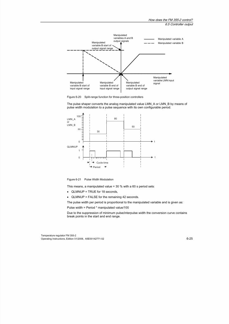
8/11/2019 FM_355-2_e
http://slidepdf.com/reader/full/fm355-2e 77/244
How does the FM 355-2 control?
6.5 Controller output
Temperature regulator FM 355-2Operating Instructions, Edition 01/2006, A5E00142771-02 6-25
Figure 6-20 Split-range function for three-position controllers
The pulse shaper converts the analog manipulated value LMN_A or LMN_B by means ofpulse width modulation to a pulse sequence with its own configurable period.
Figure 6-21 Pulse Width Modulation
This means, a manipulated value = 30 % with a 60 s period sets:
• QLMNUP = TRUE for 18 seconds,
• QLMNUP = FALSE for the remaining 42 seconds.
The pulse width per period is proportional to the manipulated variable and is given as:
Pulse width = Period * manipulated value/100
Due to the suppression of minimum pulse/interpulse width the conversion curve containsbreak points in the start and end range.
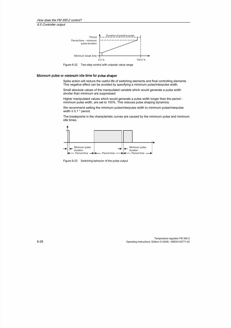
8/11/2019 FM_355-2_e
http://slidepdf.com/reader/full/fm355-2e 78/244
How does the FM 355-2 control?
6.5 Controller output
Temperature regulator FM 355-26-26 Operating Instructions, Edition 01/2006, A5E00142771-02
Figure 6-22 Two-step control with unipolar value range
Minimum pulse or minimum idle time for pulse shaper
Spike action will reduce the useful life of switching elements and final controlling elements.This negative effect can be avoided by specifying a minimum pulse/interpulse width.
Small absolute values of the manipulated variable which would generate a pulse widthshorter than minimum are suppressed.
Higher manipulated values which would generate a pulse width longer than the period -minimum pulse width, are set to 100%. This reduces pulse shaping dynamics.
We recommend setting the minimum pulse/interpulse width to minimum pulse/interpulsewidth ≤ 0.1 * period.
The breakpoints in the characteristic curves are caused by the minimum pulse and minimumidle times.
Figure 6-23 Switching behavior of the pulse output
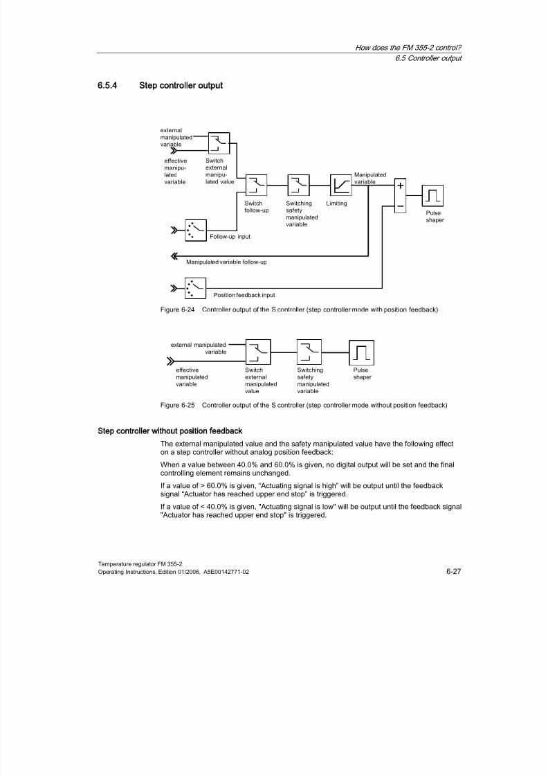
8/11/2019 FM_355-2_e
http://slidepdf.com/reader/full/fm355-2e 79/244
How does the FM 355-2 control?
6.5 Controller output
Temperature regulator FM 355-2Operating Instructions, Edition 01/2006, A5E00142771-02 6-27
6.5.4 Step controller output
Figure 6-24 Controller output of the S controller (step controller mode with position feedback)
Figure 6-25 Controller output of the S controller (step controller mode without position feedback)
Step controller without position feedback
The external manipulated value and the safety manipulated value have the following effecton a step controller without analog position feedback:
When a value between 40.0% and 60.0% is given, no digital output will be set and the finalcontrolling element remains unchanged.
If a value of > 60.0% is given, “Actuating signal is high” will be output until the feedbacksignal “Actuator has reached upper end stop” is triggered.
If a value of < 40.0% is given, "Actuating signal is low" will be output until the feedback signal"Actuator has reached upper end stop" is triggered.

8/11/2019 FM_355-2_e
http://slidepdf.com/reader/full/fm355-2e 80/244
How does the FM 355-2 control?
6.5 Controller output
Temperature regulator FM 355-26-28 Operating Instructions, Edition 01/2006, A5E00142771-02
Manual mode with step controller
You can toggle the controller to manual mode via the loop monitor. Alternatively, FB
FMT_PID may be called. Do so by setting the operator control parameter LMNS_ON = TRUEand increase or reduce the manipulated value by means of LMN_UP or LMN_DN.
On a step controller with analog position feedback you can also enable manual mode via theoperator control parameters LMN_REON and LMN_RE (external manipulated value) (as fora closed-loop controller and pulse controller).
Pulse shaper
The pulse shaper of the step controller converts the analog manipulated value to pulsesignals. The operating frequency of the controller is reduced through adaptation of theresponse threshold of the three-step element. Ensure that the physical motor actuating timematches your parameter settings.
6.5.5 Manipulated value limits
Note
To ensure optimal compensation of the controller when it reaches the control limits and forquick release out of the limit range, the limits of the manipulated values LMN_HLM andLMN_LLM must match the limits which actually affect the process. For example, if controloutput B is not wired (or if the split-range function of a closed-loop controller is disabled), you
should configure LMN_LLM according to the low limit of split-range function A. The normalsetting is here 0.0%.
Online modification of manipulated value limits (closed-loop controller and pulse controller only)
When you reduce the range of the manipulated value, and if the new unlimited manipulatedvalue is out of limits, the integral action and therefore the manipulated value is shifted (thisdescription applies to the upper limit of the manipulated value):
The reduction of the manipulated value is proportional to the change in the manipulatedvalue limit. If the manipulated value was unlimited before it was modified, it will be limited
precisely to the new value.
8/11/2019 FM_355-2_e
http://slidepdf.com/reader/full/fm355-2e 81/244
Temperature regulator FM 355-2Operating Instructions, Edition 01/2006, A5E00142771-02 7-1
Controller optimization
7
7.1
71Overview
PI/PID controller parameters
The FM 355-2 auto-tuning feature automatically sets the PI/PID controller parameters. Youcan tune the heating and cooling processes as well as split-range processes with twocounteracting final controlling elements (e.g. the final controlling elements for heating andcooling processes).
There are two tuning options:
• Tuning by operating point approach with a setpoint jump (e.g. when heating up theambient temperature to the operating point)
• Tuning at the operating point by setting a start bit.
In both cases, the process is excited by a configurable setpoint jump. After a point ofinflection is found, the PI/PID controller parameters are available, the controller switches toautomatic mode and continues control with these parameters.
The controller can be tuned with the help of the wizard included in your parameterassignment application, or via FB FMT_PID and OP.
• Cooling tuning
For controls operating with two counteracting final controlling elements (final controllingelement for the heating and cooling process), FM 355-2 determines the process gain ratio(heating/cooling gain) after a manipulated value jump, using the cooling final controllingelement.
• Tuning the response of the reference variable controller
The controller is designed for optimum response to interference. The parameter valuesdetermined in this operation would cause an overshoot between 10% to 40% of the stepamplitude as a response to setpoint jumps. In order to avoid this, the proportional actionis attenuated by the PFAC_SP parameter when a setpoint jump occurs. As an additionalmeasure, you can reduce overshoot in typical temperature processes caused by highsetpoint jump amplitudes via temporary, controlled minimum or maximum manipulatedvalue preset (control operation via the control zone).
• Saving controller parameters (SAVE_PAR or UNDO_PAR)
Controller parameters are saved before tuning starts. After tuning, you can retrieve andenable the old parameter settings by means of UNDO_PAR.

8/11/2019 FM_355-2_e
http://slidepdf.com/reader/full/fm355-2e 82/244
Controller optimization
7.2 Process types
Temperature regulator FM 355-27-2 Operating Instructions, Edition 01/2006, A5E00142771-02
7.2
72
Process types
Step response
Besides process gain GAIN_P, the parameters shown in the figure are characteristic for aprocess: Equivalent delay time TU and equivalent time constant TA.
The figure below shows the step response:
Figure 7-1 Step response
With a manipulated variable excitation of 0 to 100%, you can read the maximum actual valueramp response time per second at the inflection point: KIG = 100*GAIN_P / TA.
The table below shows the various processes you can use on the FM 355-2:
Table 7-1 Process types
Process type I Process type II Process type III
Typical temperature process(ideal situation)
Intermediate range Higher order temperatureprocess (sluggish)
TU/TA < 0.1 TU/TA approx. 0.1 TU/TA > 0.1
One dominating time constant Two approximately equivalenttime constants
Multiple time constants
The FM 355-2 is conceived for use in typical temperature processes of process type I.However, it can also be used for higher order processes of type II or III.
Note
Controlled systems with TU/TA>0.3 are normally difficult to control.

8/11/2019 FM_355-2_e
http://slidepdf.com/reader/full/fm355-2e 83/244
Controller optimization
7.2 Process types
Temperature regulator FM 355-2Operating Instructions, Edition 01/2006, A5E00142771-02 7-3
Characteristics of important temperature control systems
Controlled
variable
(actual
value)
PV
Type of process Delay time TU Time constant
TA
Ramp response
time KIG
Small, electrically heated furnace 0.5 to 1 min 5 to 15 min up to 1 KIG
Large, electrically heated furnace 1 to 5 min 10 to 20 min up to 0.3 KIG
Large, gas-heated furnace 0.2 to 5 min 3 to 60 min 0.02 to 0.5 KIG
Autoclaves 0.5 to 0.7 min 10 to 20 min
High-pressure autoclaves 12 to 15 min 200 to 300 min
Injection mould machines 0.5 to 3 min 3 to 30 min 0.1 to 0.3 KIG
Extruders 1 to 6 min 5 to 60 minPackaging machines 0.5 to 4 min 3 to 40 min 0.03 to 0.6 KIG
Distilling column 1 to 7 min 40 to 60 min 0.1 to 0.5 KIG
Steam superheater 0.5 to 2.5 min 1 to 4 min 0.03 KIG
Temperature
Room heating 1 to 5 min 10 to 60 min 0.02 KIG

8/11/2019 FM_355-2_e
http://slidepdf.com/reader/full/fm355-2e 84/244
Controller optimization
7.3 Application area
Temperature regulator FM 355-27-4 Operating Instructions, Edition 01/2006, A5E00142771-02
7.3
73
Application area
Transient response
The process must have a stable, asymptotic transient response with time lag.
The actual value must settle to steady state after a jump of the manipulated variable. Thistherefore excludes processes that already show an oscillating response without control, aswell as processes with no compensation (integrator in the control system).
Linearity and operating range
The process response must be linear across the operating range. Non-linear responseoccurs, for example, when a state of aggregation changes. Tuning must take place in a
linear part of the operating range.This means, during tuning and normal control operation non-linear effects within theoperating range must be insignificant. It is, however possible to retune the process when theoperating point changes, providing tuning is repeated in the close vicinity of the new workingpoint and non-linearity does not occur during the tuning.
If a specific static non-linearity (e.g. valve characteristics) is known, it is always advisable tocompensate this with a polyline to linearize the process response.
Disturbance in temperature processes
Disturbances such as the transfer of heat to neighboring zones must not affect the overalltemperature process too much. For example, when tuning the zones of an extruder, all
zones must be heated simultaneously.
For information on measurement noise and low-frequency interference refer to Chapter 1.13,Page 1-25.
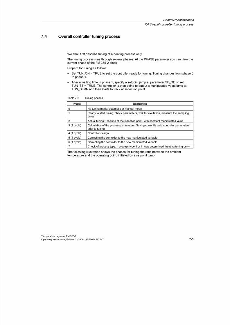
8/11/2019 FM_355-2_e
http://slidepdf.com/reader/full/fm355-2e 85/244
Controller optimization
7.4 Overall controller tuning process
Temperature regulator FM 355-2Operating Instructions, Edition 01/2006, A5E00142771-02 7-5
7.4
74
Overall controller tuning process
We shall first describe tuning of a heating process only.
The tuning process runs through several phases. At the PHASE parameter you can view thecurrent phase of the FM 355-2 block.
Prepare for tuning as follows:
• Set TUN_ON = TRUE to set the controller ready for tuning. Tuning changes from phase 0to phase 1.
• After a waiting time in phase 1, specify a setpoint jump at parameter SP_RE or setTUN_ST = TRUE. The controller is then going to output a manipulated value jump atTUN_DLMN and then starts to track an inflection point.
Table 7-2 Tuning phases
Phase Description
0 No tuning mode; automatic or manual mode
1 Ready to start tuning; check parameters, wait for excitation, measure the samplingtimes
2 Actual tuning: Tracking of the inflection point, with constant manipulated value
3 (1 cycle) Calculation of the process parameters. Saving currently valid controller parametersprior to tuning
4 (1 cycle) Controller design
5 (1 cycle) Correcting the controller to the new manipulated variable
6 (1 cycle) Correcting the controller to the new manipulated variable
7 Check of process type, if process type II or III was determined (heating tuning only).
The following illustration shows the phases for tuning the ratio between the ambienttemperature and the operating point, initiated by a setpoint jump:
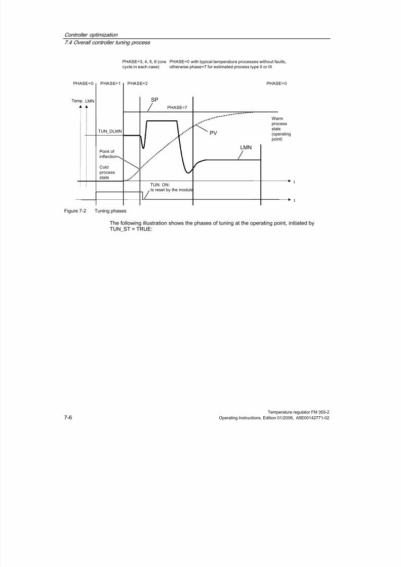
8/11/2019 FM_355-2_e
http://slidepdf.com/reader/full/fm355-2e 86/244
Controller optimization
7.4 Overall controller tuning process
Temperature regulator FM 355-27-6 Operating Instructions, Edition 01/2006, A5E00142771-02
Figure 7-2 Tuning phases
The following illustration shows the phases of tuning at the operating point, initiated byTUN_ST = TRUE:
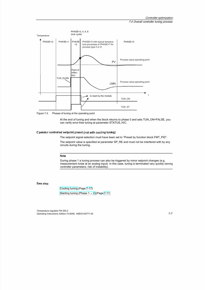
8/11/2019 FM_355-2_e
http://slidepdf.com/reader/full/fm355-2e 87/244
Controller optimization
7.4 Overall controller tuning process
Temperature regulator FM 355-2Operating Instructions, Edition 01/2006, A5E00142771-02 7-7
Figure 7-3 Phases of tuning at the operating point
At the end of tuning and when the block returns to phase 0 and sets TUN_ON=FALSE, you
can verify error-free tuning at parameter STATUS_H/C.
Operator controlled setpoint preset (not with cooling tuning)
The setpoint signal selection must have been set to “Preset by function block FMT_PID”.
The setpoint value is specified at parameter SP_RE and must not be interfered with by anycircuits during the tuning.
Note
During phase 1 a tuning process can also be triggered by minor setpoint changes (e.g.measurement noise at an analog input). In this case, tuning is terminated very quickly (wrongcontroller parameters; risk of instability).
See also
Cooling tuning (Page 7-17)
Starting tuning (Phase 1 → 2) (Page 7-11)

8/11/2019 FM_355-2_e
http://slidepdf.com/reader/full/fm355-2e 88/244
Controller optimization
7.5 Preparations
Temperature regulator FM 355-27-8 Operating Instructions, Edition 01/2006, A5E00142771-02
7.5
75
Preparations
SIMATIC and the controller
Tuning is started via the parameters TUN_ON, TUN_ST or SP_RE. You can configure theseparameters in the following ways:
• with the configuring software
• with an operator control and monitoring device
• in your user program
Write access the parameters for one cycle only.
You require FB 52 FMT_PID to perform a controller tuning. The FB 56 FMT_TUN returnsadditional details.
No tuning in safety mode
You can not initiate tuning in safety mode ! If you do so, FM 355-2 resets TUN_ON. A currenttuning process is aborted (STATUS_H/C=3009) when safety mode is switched on(SAFE_ON=TRUE).
Warning
Death, serious injury or substantial damage to assets may occur.
The LMN_REON parameter is disabled during tuning. Also, compensation circuits derived ofinterrupt limits have no effect. This can cause unwanted - even extreme - changes ofmanipulated values or actual values.
The manipulated value is determined in the tuning process. To abort tuning, you must setTUN_ON = FALSE. This re-enables LMN_REON.

8/11/2019 FM_355-2_e
http://slidepdf.com/reader/full/fm355-2e 89/244
Controller optimization
7.5 Preparations
Temperature regulator FM 355-2Operating Instructions, Edition 01/2006, A5E00142771-02 7-9
Ensuring a quasi-static initial state (Phase 0)
When low-frequency oscillation of the controlled variable occurs, e.g. because of wrong
controller parameters, you must tune the controller manually before you start auto-tuning andwait until the oscillation has decayed.
You can also choose to switch to a PI controller that has a low controller gain and highintegration time.
You must now wait until steady state is reached, that is, until both the actual value and themanipulated value have settled. An asymptotic transition or a slow drift of the actual value isalso permissible (quasi-static state, see illustration below). The manipulated variable must beconstant or fluctuate close to a constant mean value.
Note
Do not modify the manipulated variable shortly before you start tuning. A change of themanipulated variable may also be caused unintentionally by an attempt to establish testconditions (e.g. closing a furnace door)! If this has happened nonetheless, you must wait atleast for the actual value to settle to steady state after an asymptotic transition. You will,however, improve controller parameters by waiting until the transients have decayedcompletely.

8/11/2019 FM_355-2_e
http://slidepdf.com/reader/full/fm355-2e 90/244
Controller optimization
7.5 Preparations
Temperature regulator FM 355-27-10 Operating Instructions, Edition 01/2006, A5E00142771-02
Preparing for tuning (phase 0 → 1)
Set the parameter TUN-ON = TRUE. This switches the FM 355-2 ready for tuning (Phase 1).
The TUN_ON bit must only be set in steady state or during periodic transition to steady state.If the quasi-static state changes after the TUN_ON bit was set, you must reset this bit andreport the new quasi-static state to FM 355-2 by setting the TUN_ON bit again.
The figure below shows the transition to steady state:
Figure 7-4 Settling to steady state range
In Phase 1, the time prior to process excitation is used by FM 355-2 to calculate the actualvalue noise NOISE_PV, the initial rise PVDT0 and the mean value of the manipulatedvariable (initial value of the manipulated variable LMN0).
Note
In Phase 1 you should only delay process excitation until the module was able to determinethe mean value of the manipulated variable and the initial rise of the actual value (typically: 1Minute).
8/11/2019 FM_355-2_e
http://slidepdf.com/reader/full/fm355-2e 91/244
Controller optimization
7.6 Starting tuning (Phase 1 → 2)
Temperature regulator FM 355-2Operating Instructions, Edition 01/2006, A5E00142771-02 7-11
7.6
76
Starting tuning (Phase 1 → 2)
Requirements
You can start tuning in manual/compensation mode or in automatic mode. In split-rangeheating/cooling mode you can start tuning of the heating process (manipulated variable >0%) as well as of the cooling process (manipulated variable < 0%).
Prerequisite for the start of heating tuning during the cooling process is that the heating andcooling signals can simultaneously affect the process.
In this case the manipulated variable LMN0 determined in phase 1 is held constant andTUN_DLMN is directly applied in the split-range function, thus adjusting only the heatingpower (Example: LMN0=-20%, TUN_DLMN=50% -> LMN_B remains at 20%, LMN_A isswitched from 0% to 50%).
If you the controls operate after tuning
have set PID_ON = TRUE, with PID parameters.
have set PID_ON = FALSE, with PI parameters.
Tuning by approaching the operating point with setpoint jump
The tuning manipulated variable (LMN0 + TUN_DLMN) is activated by a setpoint jump(transition phase 1 → 2). The setpoint, however, will not be effective until the inflection pointhas been reached (automatic mode is not enabled until this point is reached).
The user is responsible for deciding on the excitation (TUN_DLMN) according to the
permitted actual value change. The sign of TUN_DLMN must be set depending on theintended actual value change (take into account the direction in which the control isoperating).
The setpoint jump and TUN_DLMN must be suitably matched. When the value ofTUN_DLMN is too high, you run the risk that the point of inflection is not found before 75% ofthe setpoint jump is reached.
Note
If excitation is too sharp compared to the setpoint jump, the actual value can overshootheavily (up to factor 3).

8/11/2019 FM_355-2_e
http://slidepdf.com/reader/full/fm355-2e 92/244
Controller optimization
7.6 Starting tuning (Phase 1 → 2)
Temperature regulator FM 355-27-12 Operating Instructions, Edition 01/2006, A5E00142771-02
TUN_DLMN must nonetheless be high enough to ensure that the actual value reaches atleast 22% of the setpoint jump. Otherwise, the process would remain in tuning mode
(Phase 2).Remedy: Reduce the setpoint value during inflection point tracking.
Extremely sluggish processes
If processes are extremely sluggish, it is advisable during tuning to specify a target setpointthat is somewhat lower than the desired operating point and to monitor the status bits andPV (risk of overshooting).
Tuning only in the linear range
The signals of certain processes (e.g. zinc or magnesium smelters) will pass a non-lineararea at the approach of the operating range (change of the state of aggregation).
By selecting a suitable setpoint jump, tuning can be limited to the linear range. When the
actual value has passed 75% of the setpoint jump (SP_INT-PV0), tuning is terminated.At the same time, TUN_DLMN should be reduced so that the point of inflection is guaranteedto be found before reaching 75% of the setpoint jump.
Tuning at the operating point without setpoint jump
The tuning manipulated variable (LMN0 + TUN_DLMN) is activated by setting the start bitTUN_ST (transition Phase 1 → 2). When you subsequently modify the setpoint value, thenew value will not take effect until the point of inflection has been reached (automatic modewill not be enabled until this point has been reached)
The user is responsible for deciding on the excitation (TUN_DLMN) according to thepermitted actual value change. The sign of TUN_DLMN must be set depending on the
intended actual value change (take into account the direction in which the control isoperating).
Caution
When you start tuning by setting TUN_ST/TUN_CST as well as a setpoint jump, the followingpriority applies: set TUN_ST before TUN_CST, before the setpoint jump.
Safety off at 75% is not available when you excite the process via TUN_ST. Tuning isterminated after the point of inflection is reached. However, in noisy processes the point ofinflection may be significantly exceeded.

8/11/2019 FM_355-2_e
http://slidepdf.com/reader/full/fm355-2e 93/244
Controller optimization
7.6 Starting tuning (Phase 1 → 2)
Temperature regulator FM 355-2Operating Instructions, Edition 01/2006, A5E00142771-02 7-13
Compensating operator control errors
Tuning is aborted when one of the errors listed in this table occurs.
Table 7-3 Possible operator control errors and counter measures
Fault STATUS and measures Comment
TUN_ON and TUN_ST or TUN_CST areset simultaneously
STATUS_H/C = 30001
•
Transition in Phase 0
•
TUN_ON = FALSE
Can not occur in the wizard, as thestatus of TUN_ST and TUN_CST is setto FALSE in the first screen form.
The sign of the setpoint jump does notmatch the actual value change.
Tuning termination at the point ofinflection
Safety off at 75% disabled
|TUN_DLMN| or |Effective TUN_DLMN| <5 % (End of phase 1)
Special case STATUS_H=30004:Effective manipulated value difference islimited by split-range limits, rather than bymanipulated value limits
STATUS_H/C = 30002/30004
•
Transition in phase 99 (Phase 0in a parallel tuning process)
•
Output LMN = LMN0
Either your configured value forTUN_DLMN is too low, or the
manipulated variable was near acontrol limit prior to tuning.
If STATUS_H=30004: Please note, forexample, that heating tuning is notpossible with negative TUN_DLMN ifLMN_A < 5% (Reason: cooling powermust not be adjusted).
In this case, you must prevent thecontroller from settling to the newsetpoint value and from leaving thestationary operating point withouthaving any reason to do so (notpossible in a parallel tuning process).
You should now proceed as follows:
•
Reduce the setpoint value
• TUN_ON = FALSE
•
Correct TUN_DLMN
•
Restart tuning
For step controllers without analog positionfeedback:
|Effective TUN_DLMN| < 5 % (Start ofphase 2)
STATUS_H = 30002
•
Transition in Phase 0
•
TUN_ON = FALSE
Although |TUN_DLMN| >= 5 %, theerror occurs when the value of themanipulated variable was close to acontrol limit prior to the start of tuning.
If TUN_CST:
|TUN_CLMN| or |Effective TUN_CLMN| < 5
% (End of phase 1)Special case STATUS_H=30004:Effective manipulated value difference islimited by split-range limits, rather than bymanipulated value limits
STATUS_C = 30002/30004
•
Transition in Phase 0
•
TUN_ON = FALSE
Either your configured value forTUN_CLMN is too low, or the
manipulated variable was near acontrol limit prior to tuning.
If TUN_CST:
Special case of "|Effective TUN_CLMN| < 5% (End of phase 1)":
TUN_CLMN <= -5%, but LMN_LLM > -5%.
STATUS_C = 30003
•
Transition in Phase 0
•
TUN_ON = FALSE
The low limit value LMN_LLM is toohigh (e.g. 0%) and therefore preventsoutput of cooling power.
TUN_CST, but without previous heatingtuning
STATUS_C = 30008
•
Transition in Phase 0
•
TUN_ON = FALSE

8/11/2019 FM_355-2_e
http://slidepdf.com/reader/full/fm355-2e 94/244
Controller optimization
7.6 Starting tuning (Phase 1 → 2)
Temperature regulator FM 355-27-14 Operating Instructions, Edition 01/2006, A5E00142771-02
Fault STATUS and measures Comment
Safety mode STATUS_C = 30009
•
Transition in Phase 0•
TUN_ON = FALSE
If in PHASE > 2 the FM 355-2 goes to
safety mode, this will be displayed bySTATUS_C=30009.
See also
Error views and corrective actions (Page 7-24)
8/11/2019 FM_355-2_e
http://slidepdf.com/reader/full/fm355-2e 95/244
Controller optimization
7.7 Identifying the point of inflection (Phase 2) and calculating control parameters (Phase 3, 4, 5)
Temperature regulator FM 355-2Operating Instructions, Edition 01/2006, A5E00142771-02 7-15
7.7
77
Identifying the point of inflection (Phase 2) and calculating control
parameters (Phase 3, 4, 5)
Traversing
The point of inflection is identified in phase 2, with constant manipulated value. The processforms an average of the actual value to prevent premature recognition of the point ofinflection due to noise on the PV signal:
This mean value is not active initially, that is, the average is always calculated across onecycle only. As long as the noise exceeds a certain level, the number of cycles is doubled.
The noise period and amplitude will also be determined. The search for the point of inflectionis canceled and Phase 2 is exited only when the gradient is always smaller than themaximum rise during the estimated period. TU and T_P_INF are, however, calculated at the
actual point of inflection.Tuning is only terminated if both of the following conditions also apply:
1. The actual value is more than 2*NOISE_PV away from the point of inflection.
2. The actual value has exceeded the point of inflection by 20% of P_INF.
Note
When the process is excited by a setpoint jump, tuning is terminated when the actual valueexceeds 75% of the setpoint jump (SP-PV0) (see below).
Phase 3, 4, 5 and 6 are then executed once. Tuning mode is then terminated and tuning isreturned to phase 0. The controller now always starts in automatic mode, with LMN = LMN0+ 0.75*TUN_DLMN (this applies, too, if you have operated with manual control prior to thestart of tuning).
Now check the controller function.
See also
The FB 56 FMT_TUN function block (Page 8-17)

8/11/2019 FM_355-2_e
http://slidepdf.com/reader/full/fm355-2e 96/244
Controller optimization
7.8 Checking the process type (phase 7)
Temperature regulator FM 355-27-16 Operating Instructions, Edition 01/2006, A5E00142771-02
7.8
78
Checking the process type (phase 7)
Traversing
In typical temperature processes (process type I), there is a danger that the point of inflectionwill be found too early due to noise. As a result of the shorter time at which the point ofinflection was found T_P_INF, it is possible that a process type II or III will be determined.
Phase 7 therefore checks whether or not the process type is correct. This check isperformed in automatic mode, using the recently calculated new controller parameters. Itends at least 6*TA (equivalent time constant) after the point of inflection. If process type I isdetected, the controller parameters are recalculated (STATUS_D = 122). Otherwise, thecontroller parameters remain unchanged.
The checking of the process type is canceled during tuning at the operating point when theactual value reaches the actual value PV0 which was valid at the start of tuning.
If Phase 7 is aborted by TUN_ON=FALSE, the controller parameters that have already beendetermined are retained!
Note
It is possible to start heating tuning during the cooling process. However, the order will notbe checked in phase 7.
The reverse case (to start cooling optimization during the heating process) is not critical, asphase 7 is never executed in the cooling tuning process!

8/11/2019 FM_355-2_e
http://slidepdf.com/reader/full/fm355-2e 97/244
Controller optimization
7.9 Cooling tuning
Temperature regulator FM 355-2Operating Instructions, Edition 01/2006, A5E00142771-02 7-17
7.9
79
Cooling tuning
Principle of operation
After a step of the manipulated value, FM 355-2 uses the final cooling controlling element todetermine the process gain ratio RATIOFAC (heating/cooling gain) for controls operatingwith two counteracting final controlling elements (final controlling element for the heating andcooling process). The width of the control zone CON_ZONE is also recalculated. The othercontroller parameters remain unchanged.
Requirements
You can only tune cooling following a successful heating tuning process. You must repeatheating tuning if the voltage supply to the FM 355-2 fails.
•
Manipulated variable A must be used for heating, manipulated variable B for cooling.
• RATIOFAC is effective when LMN<0.0. Thus, the split-range function must be definedaccordingly: A for LMN>=0 .0 and B for LMN<0.0.
• The user is responsible for deciding on the excitation (TUN_CLMN) according to thepermitted actual value change. The sign of TUN_CLMN must be set depending on theintended actual value change (take into account the direction in which the control isoperating). Please note that a negative TUN_CLMN increases cooling power. You can,however, also activate a manipulated value step with TUN_CLMN > 0.0 by reducingcooling power.
• You can start cooling tuning during the heating process (steady state LMN > 0%) as wellas during the cooling process (steady state LMN < 0%): Prerequisite for the start of
heating tuning during the cooling process is that the heating and cooling signals cansimultaneously affect the process.
Thermally coupled temperature zones
In a plant operated with multiple thermally coupled temperature zones (e.g. plasticprocessing machines), you should always start cooling tuning after all (!) zones havecompleted heating tuning and are settled at the operating point. Otherwise, tuning resultscan be corrupted.
Start
• After the actual value has settled at the operating point, set tuning mode on the FM 355-2
with TUN_ON=TRUE. Tuning changes from phase 0 to phase 1.• After a waiting time in phase 1, start cooling tuning with TUN_CST = TRUE.
Identifying the point of inflection
The FM 355-2 changes to PHASE 2, TUN_CST is then instantaneously reset.LMN0+TUN_CLMN is output as tuning manipulated variable. The previously determinedmanipulated variable LMN0 is held constant and TUN_CLMN is applied directly to the split-range function.
If you modify the setpoint value during phase 2, the new value is not activated until the pointof inflection has been reached (automatic mode will not be enabled until this point isreached).

8/11/2019 FM_355-2_e
http://slidepdf.com/reader/full/fm355-2e 98/244
Controller optimization
7.9 Cooling tuning
Temperature regulator FM 355-27-18 Operating Instructions, Edition 01/2006, A5E00142771-02
End of cooling tuning
Safety off at 75% is not available when you excite the process via TUN_CST. Tuning is
terminated after the point of inflection is reached. However, in noisy processes the point ofinflection may be significantly exceeded.
FM 355-2 returns to control mode (PHASE 0) when a point of inflection has been found inthe range of the process variable. FM 355-2 calculates a ratio factor RATIOFAC(heating/cooling gain) that is taken into account when the manipulated variable for thecooling range is determined in control mode.
Contrary to heating tuning, the old controller parameters will not be saved (the oldRATIOFAC has already been saved during heating tuning) and phase 4 is not executed.
That is, STATUS_D remains unchanged (still refers to heating tuning). The PI and PID datarecords of the last heating tuning process are retained so that you can also load these aftercooling tuning via LOAD_PID.
Split-range function During tuning, the gradient of the split-range function is added to the process. If you want tomodify the gradient of the split-range function after tuning, you must accordingly adapt thecontroller’s GAIN or RATIOFAC parameter.
Figure 7-5 Phases of cooling tuning
8/11/2019 FM_355-2_e
http://slidepdf.com/reader/full/fm355-2e 99/244
Controller optimization
7.10 Tuning with step controller
Temperature regulator FM 355-2Operating Instructions, Edition 01/2006, A5E00142771-02 7-19
7.10
71
Tuning with step controller
Introduction
The general information on controller tuning applies.
Peculiarities of step controllers
• Step controllers on the FM 355-2 operate without control zone.
• Phase 7 is not executed.
• No cooling tuning.
Note
The motor actuating time is not determined in the tuning process. Rather, it must bemeasured or determined prior to the start of tuning using the “Test > Determine motoractuating time” function of your parameter assignment application.
Controller design
The motor actuating time MTR_TM should be small compared to the inflection point timeT_P_INF and the equivalent dead time TU.
Controllers with a softer action are automatically generated for longer motor actuating times.
The higher the process excitation TUN_DLMN, the higher is the influence of the motoractuating time on the controller design.
PI or PID parameters
PI parameters are attenuated by 25% compared to a controller designed for closed-loopcontrollers and pulse controllers. PID parameters are also determined (but without the 25%safety margin). The PID parameters should only be used if the motor actuating time is nottoo high compared to the process parameters and when the load on the final controllingelement stays within the hysteresis due to the derivative action.
8/11/2019 FM_355-2_e
http://slidepdf.com/reader/full/fm355-2e 100/244
Controller optimization
7.10 Tuning with step controller
Temperature regulator FM 355-27-20 Operating Instructions, Edition 01/2006, A5E00142771-02
Step controller without position feedback
The output of Open/Close instructions is stopped right at the start of phase 1 (quasi manual
mode).The mean value of the manipulated variable in phase 1 (LMN0) will not be calculated.
At the start of phase 2 and during the time MTR_TM * TUN_DLMN / 100, an Open instruction(or with negative TUN_DLMN, a close instruction) is output.
When an end stop signal is triggered during the pulse action in phase 2, the effectiveTUN_DLMN is calculated as: 100 * time / MTR_TM.
When the value of the effective TUN_DLMN < 5 %, the error message STATUS_H=30002 isoutput and tuning is canceled. This error can only occur if the final controlling element isunexpectedly close to a limit.
End or cancellation of tuning
The controller starts with LMN = LMN0 + TUN_DLMN.
See also
The FB 56 FMT_TUN function block (Page 8-17)

8/11/2019 FM_355-2_e
http://slidepdf.com/reader/full/fm355-2e 101/244
Controller optimization
7.11 Tuning result
Temperature regulator FM 355-2Operating Instructions, Edition 01/2006, A5E00142771-02 7-21
7.11
71
Tuning result
Tuning result
The left numeral of STATUS_H/C indicates the tuning status (for details refer to the annex onthe assignment of DBs):
Table 7-4 Tuning result
STATUS_H/C Result
0 Default or new controller parameters have not yet been found.
10000 Suitable controller parameters were found
2xxxx Control parameters have been found via estimated values; check the controlresponse or check the STATUS_H/C diagnostic message and repeatcontroller tuning.
3xxxx An operator input error has occurred; check the STATUS_H/C diagnosticmessage and repeat controller tuning.
After the recognition of the inflection point in phase 6, the following controller parameters areupdated on the FM 355-2 and at the online instance DB of FB FMT_PID:
• Factor for the attenuation of the proportional action PFAC_SP = 0.8
• Controller GAIN
• Integration time TI (limited to ≥0.5 s)
• Integration time TD (limited to ≥1.0 s)
•
Derivative factor D_F = 5.0• Control zone on/off CONZ_ON=TRUE/FALSE
• Control zone width CON_ZONE=250/GAIN
• P_SEL = TRUE (even if it was previously a controller with integral action only)
If RATIOFAC<>0.0, then CON_ZONE is multiplied by the factor 1.5.
If a value TD<1.0 s is calculated in the tuning process, only a PI controller is determined andPID_ON as well as the PID parameters will be set to zero.
The control zone is only enabled for matching process types (process type I and II) and PIDcontrollers (CONZ_ON = TRUE).
Depending on PID_ON, control is implemented either with a PI or a PID controller. The oldcontroller parameters are saved and can be retrieved with UNDO_PAR. A PI and a PIDparameter record is saved additionally. Using LOAD_PID and making a suitable setting forPID_ON, it is also possible to switch later between the tuned PI or PID parameters.
A previously split structure (Derivative action in the feedback path) will be maintained.
Note
Verify correct operation of your controller parameters immediately after the controller tuningprocess is completed.
8/11/2019 FM_355-2_e
http://slidepdf.com/reader/full/fm355-2e 102/244
Controller optimization
7.11 Tuning result
Temperature regulator FM 355-27-22 Operating Instructions, Edition 01/2006, A5E00142771-02
Split-range function
During tuning, the gradient of the split-range function is added to the process. If you want to
modify the gradient of the split-range function after tuning, you must adapt the controller’sGAIN parameter accordingly.
Saving tuned controller parameters permanently
The new controller parameters are effective on the FM 355-2 immediately after the point ofinflection has been reached, and they are also transferred to the online instance DB of FB 52FMT_PID.
After a CPU restart, however, these parameters are overwritten with SDB parameter data(System data).
You have two options of ensuring that the FM 355-2 resumes operation after a restart withthe parameters previously determined in the tuning process:
• Set LOAD_PAR=TRUE to load (after every restart of FM 355-2) the tuned controllerparameters from the instance DB of FMT_PID into the FM 355-2.
• At the end of the tuning process, upload the controller parameter data to your parameterassignment application (upload to PG); save, compile and download your hardwareconfiguration; the tuned controller parameters are now stored in the SDB.
Regardless of this, you should also save the tuned controller parameters to the offlinestorage area of your project.
Note
The PI, PID and SAVE parameter records cannot be stored in the SDB.The correlation between SDB (System data), instance DB, parameter assignment applicationand FM 355-2 is described in the "Data Storage Operating Mechanisms in the FM 355-2"chapter.
See also
Instance DB of the FB 52 FMT_PID (Page C-1)

8/11/2019 FM_355-2_e
http://slidepdf.com/reader/full/fm355-2e 103/244

8/11/2019 FM_355-2_e
http://slidepdf.com/reader/full/fm355-2e 104/244
Controller optimization
7.13 Error views and corrective actions
Temperature regulator FM 355-27-24 Operating Instructions, Edition 01/2006, A5E00142771-02
7.13
71
Error views and corrective actions
Point of inflection not reached (only with excitation by setpoint jump)
When the actual value has passed 75% of the setpoint jump (SP-PV0), tuning is terminated.This is signaled by "Inflection point not reached" in STATUS_H/C (2xx2x).
In this case the currently valid setpoint always applies. By reducing the setpoint value it ispossible to achieve an earlier termination of the tuning function.
In typical temperature processes, terminating the tuning at 75% of the setpoint jump isnormally adequate to prevent overshoot. In processes with a greater lag (TU/TA > 0.1,process type III) caution is advised. If excitation is too sharp compared to the setpoint jump,the actual value can overshoot heavily (up to factor 3).
In processes of a higher order there will be significant overshoot if the point of inflection is
still a long way off after reaching 75% of the setpoint jump. In addition to this, the controlparameters are too sharp. You should then weaken the controller parameters and repeat theattempt.
The following schematic illustrates the overshoot of the actual value when the excitation istoo strong (process type III):
Figure 7-6 Actual value overshoot due to excess excitation
In typical temperature processes, aborting shortly before reaching the point of inflection isnot critical in terms of the controller parameters.
If you repeat the attempt, reduce TUN_DLMN/ TUN_CLMN or increase the setpoint jump.
Principle: The tuning manipulated value must match the setpoint jump.

8/11/2019 FM_355-2_e
http://slidepdf.com/reader/full/fm355-2e 105/244
Controller optimization
7.13 Error views and corrective actions
Temperature regulator FM 355-2Operating Instructions, Edition 01/2006, A5E00142771-02 7-25
Errors estimating the lag or order
The lag (STATUS_H/C = 2x1xx, 2x2xx or 2x3xx) or the order (STATUS_H/C = 21xxx or
22xxx) could not be determined correctly. Tuning then continues with an estimated value thatcannot lead to optimum controller parameters.
Repeat tuning and make sure that there is no disturbance of the actual value.
Note
A special case of a pure PT1 process is indicated by STATUS_H/C = 2x2xx (TU < samplingtime). In this case it is not necessary to repeat the attempt. Weaken the parameters if thecontroller oscillate.
Quality of the measurement signals (measurement noise, low-frequency interference)
Tuning results can be distorted by measurement noise or by low-frequency interference.Please note the following:
• The actual value should be sampled at least twice within one noise period. The degree ofnoise should not exceed 5% of the useful signal change.
• High-frequency interference can no longer be filtered out by a software block. An anti-aliasing filter should rather be applied upstream in the measuring transducer.
Figure 7-7 Aliasing effect due to exceptionally long sampling time
• If low-frequency interference occurs, you can assume that the sampling time of the FM355-2 is low enough. On the other hand, the FM 355-2 must then generate a uniformmeasuring signal by having a large interval in the mean value filtering. Mean value
filtering must extend over at least two noise periods. Internally in the block, this soonresults in higher sampling times so that the accuracy of the tuning is adversely affected.Adequate accuracy is guaranteed with at least 40 noise periods to the point of inflection.Possible measure when you repeat the test: increase TUN_DLMN/TUN_CLMN.
8/11/2019 FM_355-2_e
http://slidepdf.com/reader/full/fm355-2e 106/244
Controller optimization
7.14 Manual fine tuning in control mode
Temperature regulator FM 355-27-26 Operating Instructions, Edition 01/2006, A5E00142771-02
Overshoots
Overshoot can occur in the following situations:
Table 7-5 Cause/remedy in case of overshoot
Situation Cause Remedy
End of tuning •
Excitation by a manipulated variable stepwhich is too strong compared to thesetpoint jump (see above).
•
PI controller activated by PID_ON =FALSE
•
Increase the setpoint jump orreduce the manipulated value jump
•
If the process allows a PIDcontroller, start tuning withPID_ON = TRUE.
Tuning inPhase 7
Initially, less aggressive controller parameterswere obtained (process type III) that can leadto overshoot in Phase 7.
-
Controlmode
PI controller and with PFAC_SP = 1.0 forprocess type I
If the process allows a PID controller,start tuning with PID_ON = TRUE.
7.14
71Manual fine tuning in control mode
Introduction
The following measures can be employed in order to achieve a non-overshooting responseto setpoint changes:
Adapt control zone
During tuning, the FM 355-2 determines the control zone width CON_ZONE and, with anappropriate process type (process type I and II), a PID controller is activated: CONZ_ON =TRUE. During control mode, you can modify the control zone or switch it off completely (withCONZ_ON = FALSE).
No control zone for process type III, PI controller, step controller
Activating the control zone with higher order processes (process type III) does not normallybring any benefit since the control zone is then larger than the control range that can be
achieved with a 100% manipulated variable. There is also no advantage in activating thecontrol zone for PI controllers.
Note
Before you switch on the control zone manually, make sure that the control zone width is nottoo small. This means, the manipulated variable and actual value will oscillate if the controlzone width is too small.

8/11/2019 FM_355-2_e
http://slidepdf.com/reader/full/fm355-2e 107/244
Controller optimization
7.14 Manual fine tuning in control mode
Temperature regulator FM 355-2Operating Instructions, Edition 01/2006, A5E00142771-02 7-27
Weakening control response continuously with PFAC_SP
The control zone offers the best dynamic option of achieving a control response that is free
of overshoot. Use it whenever possible, that is, on PID controllers for process type I and II.With PI controllers, process type III or setpoint jumps within the control zone you canattenuate control response via the parameter PFAC_SP. This parameter specifies theamount of P action that is affective for setpoint jumps.
Regardless of the process type, PFAC_SP is set to a default value of 0.8 by the tuningfunction; you can later modify this value if required. To limit overshoot during setpoint jumps(with otherwise correct controller parameters) to approximately 2%, the following values areadequate for PFAC_SP:
Process type I Process type II Process type III
Typical temperature process Intermediate range Higher order temperature process
PI 0.8 0.82 0.8
PID 0.6 0.75 0.96
Adapt the default factor (0.8) especially under the following situations:
• Process type I with PID (0.8 →0.6): With PFAC_SP = 0.8, setpoint jumps will still lead toapprox. 18% overshoot.
• Process type III with PID (0.8 →0.96): With PFAC_SP = 0.8, the setpoint jumps isattenuated too heavily. This leads to a significant loss of tuning time.
Example of control response attenuation with PFAC_SP
Table 7-6 Parameter list for the example
Process parameters Controller parameters
GAIN = 6 GAIN = 1.45
T1 = 50 s TI = 19.6 s
T2 = 5 s
Figure 7-8 Trend showing three attempts, each with a setpoint jump from 0 to 60
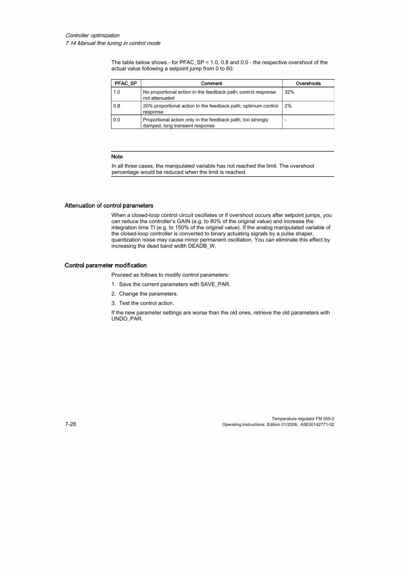
8/11/2019 FM_355-2_e
http://slidepdf.com/reader/full/fm355-2e 108/244
Controller optimization
7.14 Manual fine tuning in control mode
Temperature regulator FM 355-27-28 Operating Instructions, Edition 01/2006, A5E00142771-02
The table below shows - for PFAC_SP = 1.0, 0.8 and 0.0 - the respective overshoot of theactual value following a setpoint jump from 0 to 60:
PFAC_SP Comment Overshoots
1.0 No proportional action in the feedback path; control responsenot attenuated
32%
0.8 20% proportional action in the feedback path; optimum controlresponse
2%
0.0 Proportional action only in the feedback path; too stronglydamped, long transient response
-
Note
In all three cases, the manipulated variable has not reached the limit. The overshootpercentage would be reduced when the limit is reached.
Attenuation of control parameters
When a closed-loop control circuit oscillates or if overshoot occurs after setpoint jumps, youcan reduce the controller’s GAIN (e.g. to 80% of the original value) and increase theintegration time TI (e.g. to 150% of the original value). If the analog manipulated variable ofthe closed-loop controller is converted to binary actuating signals by a pulse shaper,
quantization noise may cause minor permanent oscillation. You can eliminate this effect byincreasing the dead band width DEADB_W.
Control parameter modification
Proceed as follows to modify control parameters:
1. Save the current parameters with SAVE_PAR.
2. Change the parameters.
3. Test the control action.
If the new parameter settings are worse than the old ones, retrieve the old parameters withUNDO_PAR.
8/11/2019 FM_355-2_e
http://slidepdf.com/reader/full/fm355-2e 109/244
Controller optimization
7.15 Parallel tuning of controller channels
Temperature regulator FM 355-2Operating Instructions, Edition 01/2006, A5E00142771-02 7-29
7.15
71
Parallel tuning of controller channels
Neighboring zones (strong temperature coupling effect)
When two or multiple controllers of a module are used to control the temperature, forexample, on a plate (e.g. two heaters and two measured actual values with strongtemperature coupling), you have the option of parallel controller tuning. Proceed as follows:
1. Define the channel group in Zone A or Zone B.
2. Start tuning in one of these channels. Tuning of the other channels will then be startedautomatically.
Note
The user must ensure that the setpoint jumps are set concurrently when the process isexcited via setpoint jump. You can use the wizard to specify the parameters PID_ON andTUN_DLMN/TUN_CLMN for one channel only. You must specify the parameters for theother channels in the corresponding instance DBs of FB FMT_PID before you start tuning.
Tuning is aborted
Tuning of all channels is aborted if an error occurs in one of the channels (Phase 0 or end ofphase 1).
The user can reset tuning by setting TUN_ON=FALSE at any of the participating channels.
When a channel goes into safety mode, tuning of all other participating channels is alsoswitched off.
The wizard shows only the status information of the selected channel. For all other channels,the causes of error are found in the corresponding instance DBs.
Advantage
Each participating controller will output its tuning manipulated variable until all controllershave exited phase 2. This avoids that the controller that completes tuning first corrupts thetuning result of the other controller due to the change in its manipulated variable.
Caution
When 75% of the setpoint jump is reached at one of the participating channels, tuning is not
terminated (risk of overshoot). Automatic mode is only started after all participatingcontrollers have terminated tuning.
Neighboring zones (weak temperature coupling effect)
As a general rule, tuning should be carried out to reflect the way in which the control willwork later. When zones are operated in parallel during production so that the temperaturedifferences between the zones remain the same, the temperature level of the neighboringzones ought to be increased accordingly during tuning.
Temperature differences at the beginning of a trial are irrelevant since they will becompensated in the initial heating process (→initial rise = 0).

8/11/2019 FM_355-2_e
http://slidepdf.com/reader/full/fm355-2e 110/244
Controller optimization
7.16 Saving and retrieving controller parameters
Temperature regulator FM 355-27-30 Operating Instructions, Edition 01/2006, A5E00142771-02
7.16
71
Saving and retrieving controller parameters
Back-up file records
The FM 355-2 features an effective parameter record system as well as a backed upparameter record system. Save and retrieval operations are performed by means ofSAVE_PAR or UNDO_PAR in OP structure of FB FMT_PID.
For example, prior to a manual change you can save the current parameters via SAVE_PAR= TRUE. You can retrieve the last saved controller parameters via UNDO_PAR = TRUE andenable them for the controller. SAVE_PAR or UNDO_PAR is reset by FMT_PID at the end ofthis action.
If you want to know the values in the current parameter record or in the backed up parameterrecord, you can retrieve this information via FB FMT_PID (READ_PAR = TRUE) orFMT_TUN (READ_OUT = TRUE):
Current parameters in the PAR structure of
FMT_PID:
Parameters included in the backup of the
FMT_TUN output parameters:
PFAC_SP SAV_PFAC
GAIN SAV_GAIN
TI SAV_TI
TD SAV_TD
D_F SAV_D_F
CON_ZONE SAV_CONZ
RATIOFAC SAV_RATI
CONZ_ON SAV_CZONP_SEL SAV_PSEL
Note
At the end of controller tuning, the saved parameters are overwritten with parameter datathat were valid prior to tuning (Exception: this intermediate saving operation is discarded in acooling tuning process).

8/11/2019 FM_355-2_e
http://slidepdf.com/reader/full/fm355-2e 111/244
Controller optimization
7.16 Saving and retrieving controller parameters
Temperature regulator FM 355-2Operating Instructions, Edition 01/2006, A5E00142771-02 7-31
Change between PI and PID parameters
After tuning, the PI and PID parameters are saved on the FM355-2. These parameter
records are loaded by setting LOAD_PID in the structure OP of FB FMT_PID. If PID_ON inthe structure PAR = TRUE, the PID parameter record is copied to the effective controllerparameters; otherwise, the PI parameter record is copied. LOAD_PID is reset by FMT_PIDat the end of this action. Of course, the value of PID_ON is retained, as it is not an operatorcontrol parameter.
If you want to know which values are stored in the PI or PID parameter record, you can viewthese data via FB FMT_TUN by setting READ_OUT = TRUE:
PI parameter record PID parameter record
Controller GAIN PI_GAIN PID_GAIN
Integration time PI_TI PID_TI
Derivative time 0.0 PID_TD
Note
Please note the following:
• Controller parameters are only written back with UNDO_PAR or LOAD_PID if thecontroller gain (SAV_GAIN, PID_GAIN or PI_GAIN) is not equal to zero:
• This strategy takes into account the situation that no tuning has yet been made or thatPID parameters are missing. For example, if PID_ON was TRUE and PID_GAIN = 0.0,PID_ON is set to FALSE and the PI parameters will be copied.
•
D_F, PFAC_SP are set to default values by the tuning. The user can later modify them.LOAD_PID does not modify these parameters.
• With LOAD_PID, the control zone is always recalculated (CON_ZONE = 250/GAIN or375/GAIN if RATIOFAC <> 0.0), irrespective of the status CONZ_ON = FALSE.
Pulse-free changeover with LOAD_PID and UNDO_PAR
The changeover is performed so that the sum of the proportional action and integral actionstays equal. A changeover from PID to PI triggers a jump of the manipulated variable, as the
derivative action is disabled. Initially, the changeover from PI to PID is pulse-free. After a fewcycles, however, the derivative action will lead to a fast change.

8/11/2019 FM_355-2_e
http://slidepdf.com/reader/full/fm355-2e 112/244
Controller optimization
7.16 Saving and retrieving controller parameters
Temperature regulator FM 355-27-32 Operating Instructions, Edition 01/2006, A5E00142771-02

8/11/2019 FM_355-2_e
http://slidepdf.com/reader/full/fm355-2e 113/244
Temperature regulator FM 355-2Operating Instructions, Edition 01/2006, A5E00142771-02 8-1
Integrating the FM 355-2 into the user program
8
8.1
81Overview of the function blocks
Overview of the function bocks
Function block Effect
FB 52 FMT_PID for operating and observing controller parameters via the CPU as well asonline changes to them
FB 53 FMT_PAR for online changes to further parameters
FB 54 FMT_CJ_T for reading or writing the reference junction temperature from/into themodule.
FB 55 FMT_DS1 for reading the DS 1 diagnosis data set off the module
FB 56 FMT_TUN for supporting controller optimization.
FB 57 FMT_PV for reading or writing process values (analog and digital input values) tosupport commissioning.
Note
Downloading the controller and operating parameters with FB FMT_PID
After downloading the controller parameters with LOAD_PAR = TRUE or the operatingparameters with LOAD_OP = TRUE the parameters do not take effect immediately. Onlyafter the cycle time of the FM 355-2 (depending on the number of channels up to 500 ms)are the controller parameters available to read back with READ_PAR or the outputparameters available with READ_OUT. This also applies after downloading the system data(CPU transition from STOP to RUN) as well as when reading the output parameters via theFB FMT_TUN.

8/11/2019 FM_355-2_e
http://slidepdf.com/reader/full/fm355-2e 114/244
Integrating the FM 355-2 into the user program
8.2 The FB 52 FMT_PID - General
Temperature regulator FM 355-28-2 Operating Instructions, Edition 01/2006, A5E00142771-02
Creating and supplying power to instance DB
Before you program the module with the user program you must create an instance DB for
each controller channel you intend to use and supply it with data.1. Under STEP 7 generate the instance DBs for the controller channels as data blocks with
assigned function block (e.g. FMT_PID).
2. For each instance DB enter the module address in the MOD_ADDR parameter.
The FM 355-2 module address is defined when your hardware is configured. Adopt thestart address from the HW Config.
3. Enter the channel number of the corresponding controller channel (0,1,2 or 3) into theCHANNEL parameter for the instance DBs of the FMT_PID, FMT_PAR and FMT_TUN-
4. Store the instance DBs.
8.2
82
The FB 52 FMT_PID - General
How FB 52 FMT_PID is used
The FM 355-2 is linked to the user program via the FB FMT_PID. You can use this FB tomodify operating parameters during operation. For example, you can specify a set point andthe output value or switch to external output value specification (manual operation).
The data required for the FMT_PID are stored in an instance DB on the CPU The FMT_PIDis program controlled to read data off the FM 355-1 and to write data onto the FM_PID.
The individual parameters are described in the Online Help information and in the annex"Assignment of DBs".
Call
The FMT_PID must be called in the same OB as all other FBs that access the same FM 355-2.
The FMT_PID is called in the time interrupt OB. It requires and initialization run, which istriggered in the CPU start up by setting the COM_RST=TRUE parameter. After theinitialization run, the FB FMT_PID sets the COM_RST parameter to FALSE.
See also
Instance DB of the FB 52 FMT_PID (Page C-1)

8/11/2019 FM_355-2_e
http://slidepdf.com/reader/full/fm355-2e 115/244
Integrating the FM 355-2 into the user program
8.3 The FB 52 FMT_PID function block - Details
Temperature regulator FM 355-2Operating Instructions, Edition 01/2006, A5E00142771-02 8-3
8.3
83
The FB 52 FMT_PID function block - Details
8.3.1 Operating via the FB 52 FMT_PID
Transferring the operating parameters
The operating parameters (e.g. setpoint, manual manipulated variable) of the FM 355-2 aretransferred cyclically from the FMT_PID to the FM 355-2). Operating parameters are all staticvariables of instance DB in the structure OP.
If you set LOAD_OP = TRUE, the operating parameters are transferred to the FM 355-2 bymeans of SFB WRREC.
After data transfer as been completed the LOAD_OP parameter of the FB FMT_PID is set atFALSE again. When using the FM 355-2 in a decentralized periphery, this may take a fewcall cycles.
When transferring data with LOAD_OP, the output parameters are also read off the FM.
Note
You can shorten the running time of the block "See section "Technical data for functionblocks") if you do not set LOAD_OP. In this case the block uses the input and output rangesof the module for fast data transfer. The following restrictions apply:
• The data transfer of the OP parameters via the input and output range takes place up to
and including LMN_DN only.• Even with a centralized configuration the data transfer requires 3 to 4 cycles.
• During automatic operation only the SP_RE setpoint and during manual operation onlythe LMN_RE manual manipulated variable are transferred.
• Data transfer via the input and output ranges does not work if two instances of the FBFMT_PIC access the same channel number of a module.
• The FB FMT_PID automatically sets LOAD_OP to TRUE,
– if you have set one of the following parameters: TUN_ST, TUN_CST, SAVE_PAR,UNDO_PAR and LOAD_PID,
– if you modify TUN-ON
– and if you modify the manipulated variable SP_RE
in the aforementioned cases the operating values are transferred once via SFBWRREC.
See also
Technical data of function blocks (Page A-9)

8/11/2019 FM_355-2_e
http://slidepdf.com/reader/full/fm355-2e 116/244
Integrating the FM 355-2 into the user program
8.3 The FB 52 FMT_PID function block - Details
Temperature regulator FM 355-28-4 Operating Instructions, Edition 01/2006, A5E00142771-02
8.3.2 Observing via the FB 52 FMT_PID
Reading the process values
The FB FMT_PID reads output parameters cyclically (e.g. actual value, manipulated variableor internal states) off the FM 355-2
They are stored in the static variables of the instance DB in the OUT structure.
If you set READ_OUT = TRUE, the output parameters are transferred to the FM 355-2 bymeans of SFB RDREC. With LOAD_OP = TRUE the operating and output parameters aretransferred.
After data transfer as been completed the READ-OUT parameter of the FB FMT_PID is setat FALSE again. When using the FM 355-2 in a decentralized periphery, this may take a fewcall cycles.
Note
You can shorten the running time of the block "See section "Technical data for functionblocks") if you do not set READ_OUT and/or LOAD_OP. In this case the block uses the inputand output ranges of the module for fast data transfer. The following restrictions apply:
• The parameter SP (setpoint off the FM), ER (control deviation), DISV (disturbancevariable), LMN_A, LMN_B, PHASE, STATUS_H, STATUS_C, STATUS_D andZONE_TUN are not read off the FM (see Annex "Assignment of the DBs").
• Even with a centralized configuration the data transfer requires 3 to 4 cycles.
• Data transfer via the input and output ranges does not work if two instances of the FB
FMT_PIC access the same channel number of a module.• The FB FMT_PID automatically sets READ_OUT to TRUE,
– during an optimization procedure QTUN_ON = TRUE,
– and if you modify the manipulated variable SP_RE.
Error displays
The output parameter RET_VALU contains the feedback value STATUS (byte 2 and 3) ofthe SFBs 52 and 53 (corresponding to the RET_VAL of the SFCs 58/59). The RET_VALUcan be evaluated if the READ_PAR and LOAD_PAR parameters have not been reset.
A peripheral access error can occur when calling the FMT_PID if the FM 355-2 is notplugged in or has no voltage supply. In the case the CPU goes into STOP, if no OB 122 isloaded onto the CPU.
If an error occurs when reading/writing a data set, QMOD_F and QCH_F must be set. Ifparameters have been assigned incorrectly, QPAR_F and QCH_F must be set.
See also
List of RET_VALU messages (Page D-1)

8/11/2019 FM_355-2_e
http://slidepdf.com/reader/full/fm355-2e 117/244
Integrating the FM 355-2 into the user program
8.3 The FB 52 FMT_PID function block - Details
Temperature regulator FM 355-2Operating Instructions, Edition 01/2006, A5E00142771-02 8-5
8.3.3 Modify controller parameters via the FB 52 FMT_PID
Procedure
Controller parameters (e.g. controller gain, integration time) are to be found in the PARstructure. Controller parameters are first assigned via the project planning software and aretransferred to the FM 355-2 via the system data.
Modifying controller parameters via the FMT_PID makes sense if you want to modify themduring operation depending on process states. To do this, proceed as follows:
1. Set the READ_PAR parameter of the FMT_PID to TRUE.
The FB then reads all controller parameters off the FM 355-2 and stores them in itsinstance DB. The instance DB of the FMT_PID has now been matched with the projectplanning software (system data). When the parameters have been read successfully, theFMT_PID sets the READ_PAR parameter to FALSE. When using the FM 355-2 in a
decentralized periphery, this may take a few call cycles.2. If READ_PAR = FALSE, you can now modify individual controller parameters in theinstance DB of the FMT_PID in the user program.
For this purpose call the FB FMT_PID with LOAD_PAR = TRUE. The FMT_PID thentransfers all controller parameters out of the instance DB to the FM. Once the parametershave been transferred successfully, the FMT_PID resets the LOAD_PAR parameter.When using the FM 355-2 in a decentralized periphery, this may take a few call cycles.
Note
Please not that each time the CPU starts up (transition from STOP to RUN), the parametersin the FM 355-2 are overwritten with the values from the system data.
Figure 8-1 Operating, observing and assigning parameters via the FB FMT_PID and via system
data
See also
Operative mechanism of data storage on the FM 355-2 (Page 2-9)

8/11/2019 FM_355-2_e
http://slidepdf.com/reader/full/fm355-2e 118/244
Integrating the FM 355-2 into the user program
8.3 The FB 52 FMT_PID function block - Details
Temperature regulator FM 355-28-6 Operating Instructions, Edition 01/2006, A5E00142771-02
8.3.4 Program-controlled reparameterization
Effects
By means of program-controlled modification of parameter assignments (LOAD_PAR,LOAD_OP) of the FM 355-2 by the FMT_PID, its running time is increased. The newparameters always take immediate effect.
8.3.5 Relation between FB parameters and
Overview
The following figures show the relationship between the FMT_PID and the parameter
assignment interface of the controller module.As far as three-component controllers and ratio/mixing controllers are concerned, theparameters affect the same point as with fixed setpoint or cascade controllers. This alsoapplies to the parameters that are equally in place for continuous controllers, controllers withpulse output as well as step-action controllers. It is generally correct that the buttons of thesame time contain the same parameters. Hence, for reasons of clarity, not all structurediagrams are depicted and not all parameters are marked in all figures.
However, the parameters of FMT_PID are contained in all figures, except the MOD_ADDR,CHANNEL, QMOD_F, QPAR_F, QCH_F, QLMNR_ON, RET_VALU, COM_RST,LOAD_PAR, READ_PAR, READ_OUT and LOAD_OP parameters.
The following figures show the places in the module affected by the parameters of theFMT_PID.
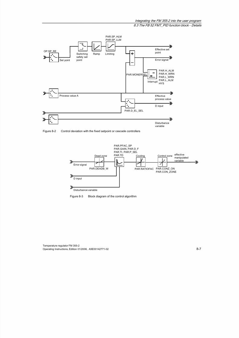
8/11/2019 FM_355-2_e
http://slidepdf.com/reader/full/fm355-2e 119/244
Integrating the FM 355-2 into the user program
8.3 The FB 52 FMT_PID function block - Details
Temperature regulator FM 355-2Operating Instructions, Edition 01/2006, A5E00142771-02 8-7
Figure 8-2 Control deviation with the fixed setpoint or cascade controllers
Figure 8-3 Block diagram of the control algorithm

8/11/2019 FM_355-2_e
http://slidepdf.com/reader/full/fm355-2e 120/244
Integrating the FM 355-2 into the user program
8.3 The FB 52 FMT_PID function block - Details
Temperature regulator FM 355-28-8 Operating Instructions, Edition 01/2006, A5E00142771-02
Figure 8-4 Controller output of the continuous-action controller (FM 355-2C
Figure 8-5 Controller output of the pulse controller (FM 355-2 S)
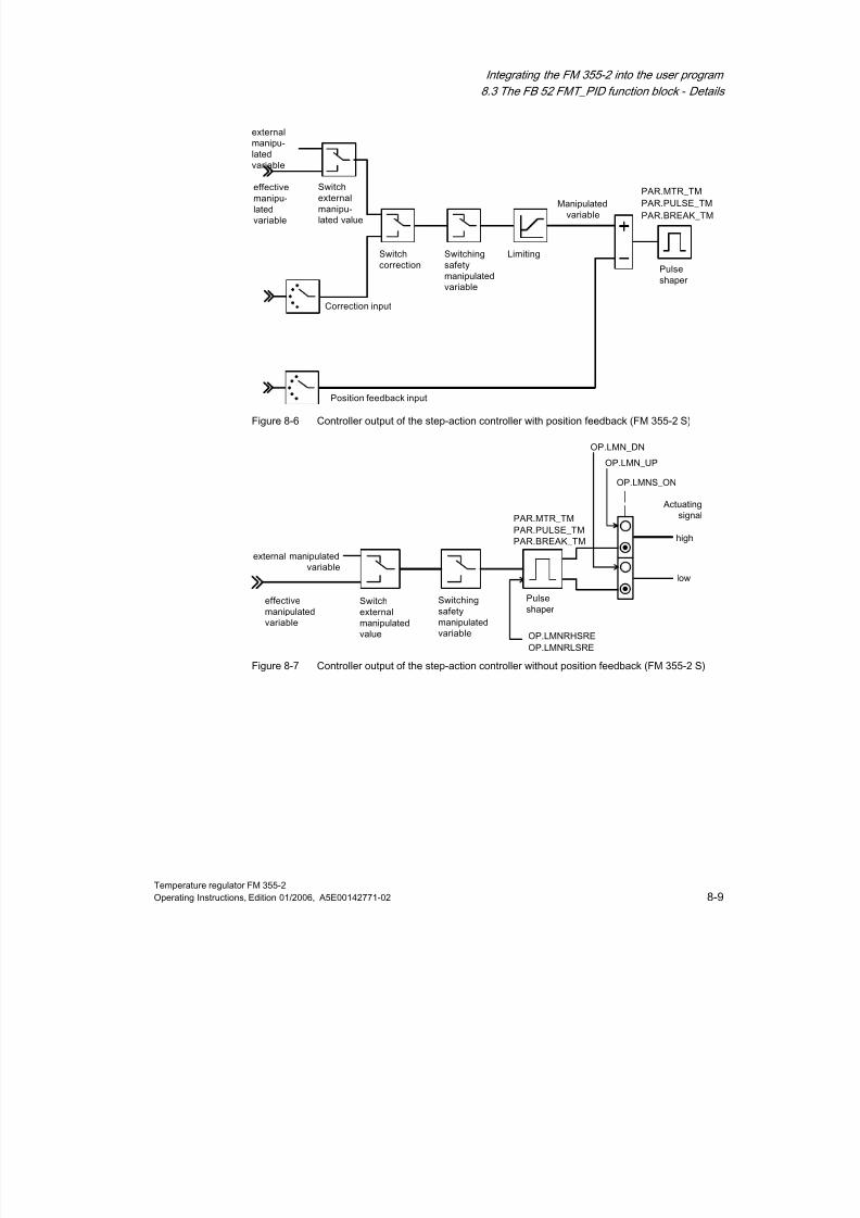
8/11/2019 FM_355-2_e
http://slidepdf.com/reader/full/fm355-2e 121/244
Integrating the FM 355-2 into the user program
8.3 The FB 52 FMT_PID function block - Details
Temperature regulator FM 355-2Operating Instructions, Edition 01/2006, A5E00142771-02 8-9
Figure 8-6 Controller output of the step-action controller with position feedback (FM 355-2 S)
Figure 8-7 Controller output of the step-action controller without position feedback (FM 355-2 S)

8/11/2019 FM_355-2_e
http://slidepdf.com/reader/full/fm355-2e 122/244
Integrating the FM 355-2 into the user program
8.3 The FB 52 FMT_PID function block - Details
Temperature regulator FM 355-28-10 Operating Instructions, Edition 01/2006, A5E00142771-02
The following figures show the points in the module the output parameters of the FBFMT_PID are generated.
Figure 8-8 Control deviation determination for fixed value or cascade controllers
Figure 8-9 Controller output of the continuous-action controller (FM 355-2 C)

8/11/2019 FM_355-2_e
http://slidepdf.com/reader/full/fm355-2e 123/244
Integrating the FM 355-2 into the user program
8.3 The FB 52 FMT_PID function block - Details
Temperature regulator FM 355-2Operating Instructions, Edition 01/2006, A5E00142771-02 8-11
Figure 8-10 Controller output of the pulse controller (FM 355-2 S)
Figure 8-11 Controller output of the step-action controller with position feedback (FM 355-2 S
Figure 8-12 Controller output of the step-action controller without position feedback (FM 355-2 S)

8/11/2019 FM_355-2_e
http://slidepdf.com/reader/full/fm355-2e 124/244
Integrating the FM 355-2 into the user program
8.4 The FB 53 FMT_PAR function block - General information
Temperature regulator FM 355-28-12 Operating Instructions, Edition 01/2006, A5E00142771-02
8.4 84The FB 53 FMT_PAR function block - General information
Use
The FMT_PAR supports the online modification of further parameters which cannot bedefined via the FMT_PID.
To save running time, the FMT_PAR should only be called using LOAD = TRUE ifparameters are to be modified.
Call
The FMT_PAR must be called in the same OB as all other FBs that access the sameFM 355-2.
With the FMT_PAR each call enables you to modify one each of the REAL parameters listedin the following table as well as one of the INT parameters.
The prescribed value is assigned to the parameter via the index numbers from the tablebelow, which you specify for the INDEX parameter in the instance DB of the FMT_PAR.
If you wish to modify several parameters, you must call the same instance DB several timesin succession using LOAD_PAR=TRUE and different index numbers.
The output parameter RET_VALU contains the feedback value STATUS (byte 2 and 3) ofthe SFBs 52 and 53 (corresponding to the RET_VAL of the SFCs 58/59).
When using the FM 355-2 in a decentralized periphery, this may take a few call cycles untilthe parameters are transferred to the FM 355-2. As long as the transfer has not beencompleted, the LOAD_PAR parameter retains the value TRUE. So keep repeating your call
of FB FMT_PAR when modifying parameters until LOAD_PAR is = FALSE.
Note
Please not that each time the CPU starts up (transition from STOP to RUN), the parametersin the FM 355-2 are overwritten with the parameters from the system data.

8/11/2019 FM_355-2_e
http://slidepdf.com/reader/full/fm355-2e 125/244
Integrating the FM 355-2 into the user program
8.4 The FB 53 FMT_PAR function block - General information
Temperature regulator FM 355-2Operating Instructions, Edition 01/2006, A5E00142771-02 8-13
Example
During operation you want to modify the start up time of the ramp for the reference input and,
depending on the process state, use different analog input values as the actual value.• In order to parameterize the start-up time of the ramp for the reference input at 10.0,
during operation you call the FMT_PAR with INDEX = 30 and VALUE_R = 10.0.
• If you wish to parameterize the analog input value 4 of the module as the actual value,call the FMT_PAR with INDEX = 50 and VALUE_I = 4 during operation.
Table 8-1 List of the REAL and INT parameters to be modified with FMT_PAR
Data type Description Index number
- no parameter selected 0
REAL Filter time constant for the analog input 1
REAL Standardization of analog input end of measuring range equivalent to100% 2
REAL Standardization of analog input end of measuring range equivalent to0%
3
REAL Polyline, interpolation point 1 supply side 4
REAL Polyline, interpolation point 2 supply side 5
REAL Polyline, interpolation point 3 supply side 6
REAL Polyline, interpolation point 4 supply side 7
REAL Polyline, interpolation point 5 supply side 8
REAL Polyline, interpolation point 6 supply side 9
REAL Polyline, interpolation point 7 supply side 10
REAL Polyline, interpolation point 8 supply side 11REAL Polyline, interpolation point 9 supply side 12
REAL Polyline, interpolation point 10 supply side 13
REAL Polyline, interpolation point 11 supply side 14
REAL Polyline, interpolation point 12 supply side 15
REAL Polyline, interpolation point 13 supply side 16
REAL Polyline, interpolation point 1 output side 17
REAL Polyline, interpolation point 2 output side 18
REAL Polyline, interpolation point 3 output side 19
REAL Polyline, interpolation point 4 output side 20
REAL Polyline, interpolation point 5 output side 21REAL Polyline, interpolation point 6 output side 22
REAL Polyline, interpolation point 7 output side 23
REAL Polyline, interpolation point 8 output side 24
REAL Polyline, interpolation point 9 output side 25
REAL Polyline, interpolation point 10 output side 26
REAL Polyline, interpolation point 11 output side 27
REAL Polyline, interpolation point 12 output side 28
REAL Polyline, interpolation point 13 output side 29
REAL Start-up time of the ramp for the reference input 30
REAL Safety manipulated value 31
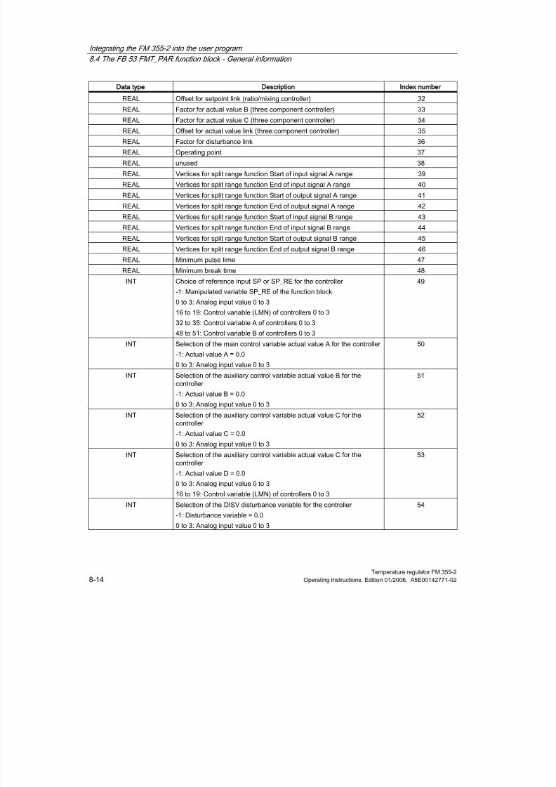
8/11/2019 FM_355-2_e
http://slidepdf.com/reader/full/fm355-2e 126/244
Integrating the FM 355-2 into the user program
8.4 The FB 53 FMT_PAR function block - General information
Temperature regulator FM 355-28-14 Operating Instructions, Edition 01/2006, A5E00142771-02
Data type Description Index number
REAL Offset for setpoint link (ratio/mixing controller) 32
REAL Factor for actual value B (three component controller) 33REAL Factor for actual value C (three component controller) 34
REAL Offset for actual value link (three component controller) 35
REAL Factor for disturbance link 36
REAL Operating point 37
REAL unused 38
REAL Vertices for split range function Start of input signal A range 39
REAL Vertices for split range function End of input signal A range 40
REAL Vertices for split range function Start of output signal A range 41
REAL Vertices for split range function End of output signal A range 42
REAL Vertices for split range function Start of input signal B range 43REAL Vertices for split range function End of input signal B range 44
REAL Vertices for split range function Start of output signal B range 45
REAL Vertices for split range function End of output signal B range 46
REAL Minimum pulse time 47
REAL Minimum break time 48
INT Choice of reference input SP or SP_RE for the controller
-1: Manipulated variable SP_RE of the function block
0 to 3: Analog input value 0 to 3
16 to 19: Control variable (LMN) of controllers 0 to 3
32 to 35: Control variable A of controllers 0 to 3
48 to 51: Control variable B of controllers 0 to 3
49
INT Selection of the main control variable actual value A for the controller
-1: Actual value A = 0.0
0 to 3: Analog input value 0 to 3
50
INT Selection of the auxiliary control variable actual value B for thecontroller
-1: Actual value B = 0.0
0 to 3: Analog input value 0 to 3
51
INT Selection of the auxiliary control variable actual value C for thecontroller
-1: Actual value C = 0.0
0 to 3: Analog input value 0 to 3
52
INT Selection of the auxiliary control variable actual value C for thecontroller
-1: Actual value D = 0.0
0 to 3: Analog input value 0 to 3
16 to 19: Control variable (LMN) of controllers 0 to 3
53
INT Selection of the DISV disturbance variable for the controller
-1: Disturbance variable = 0.0
0 to 3: Analog input value 0 to 3
54
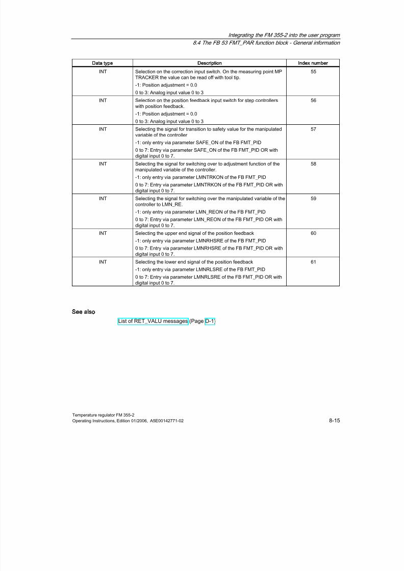
8/11/2019 FM_355-2_e
http://slidepdf.com/reader/full/fm355-2e 127/244
Integrating the FM 355-2 into the user program
8.4 The FB 53 FMT_PAR function block - General information
Temperature regulator FM 355-2Operating Instructions, Edition 01/2006, A5E00142771-02 8-15
Data type Description Index number
INT Selection on the correction input switch. On the measuring point MP
TRACKER the value can be read off with tool tip.-1: Position adjustment = 0.0
0 to 3: Analog input value 0 to 3
55
INT Selection on the position feedback input switch for step controllerswith position feedback.
-1: Position adjustment = 0.0
0 to 3: Analog input value 0 to 3
56
INT Selecting the signal for transition to safety value for the manipulatedvariable of the controller
-1: only entry via parameter SAFE_ON of the FB FMT_PID
0 to 7: Entry via parameter SAFE_ON of the FB FMT_PID OR withdigital input 0 to 7.
57
INT Selecting the signal for switching over to adjustment function of themanipulated variable of the controller.
-1: only entry via parameter LMNTRKON of the FB FMT_PID
0 to 7: Entry via parameter LMNTRKON of the FB FMT_PID OR withdigital input 0 to 7.
58
INT Selecting the signal for switching over the manipulated variable of thecontroller to LMN_RE.
-1: only entry via parameter LMN_REON of the FB FMT_PID
0 to 7: Entry via parameter LMN_REON of the FB FMT_PID OR withdigital input 0 to 7.
59
INT Selecting the upper end signal of the position feedback
-1: only entry via parameter LMNRHSRE of the FB FMT_PID0 to 7: Entry via parameter LMNRHSRE of the FB FMT_PID OR withdigital input 0 to 7.
60
INT Selecting the lower end signal of the position feedback
-1: only entry via parameter LMNRLSRE of the FB FMT_PID
0 to 7: Entry via parameter LMNRLSRE of the FB FMT_PID OR withdigital input 0 to 7.
61
See also
List of RET_VALU messages (Page D-1)

8/11/2019 FM_355-2_e
http://slidepdf.com/reader/full/fm355-2e 128/244
Integrating the FM 355-2 into the user program
8.5 The FB 54 FMT_CJ_T function block
Temperature regulator FM 355-28-16 Operating Instructions, Edition 01/2006, A5E00142771-02
8.5
85
The FB 54 FMT_CJ_T function block
Use
The FMT_CJ_T is for reading the measured reference junction temperature and for changingthe parameterized reference junction temperature online. This is necessary of a temperaturecontrol system with more than one FM 355-2 with thermal element inputs is to be operatedwithout a Pt 100 having to be connected to each FM 355-2.
If, for example, an FM 355-2 measures the reference junction temperature of an extrudercontrol system with more than four heating zones, it can be read with READ_CJ = TRUE onthe CJ_T_OUT parameter and can be parameterized for the other FM 355-2 via theCJ_TEMP and LOAD_CJ.
On parameter CJ_T_OUT the reference junction temperature measured at the referencepoint is expressed degrees C or in degrees F (depending on which temperature unit hasbeen parameterized).
On parameter CJ_T_OUT 0.0. is shown if:
• no sensor of the "thermoelement" type has been parameterized,
• the parameterized reference junction temperature was selected on all analog inputs,
• the internal compensation was selected on all analog inputs,
The output parameter RET_VALU contains the feedback value STATUS (byte 2 and 3) ofthe SFBs 52 and 53 (corresponding to the RET_VAL of the SFCs 58/59). The values ofRET_VALU are described in the reference manual System software for S7-300/S7-400system and standard functions .
When using the FM 355-2 in a decentralized periphery, it may take a few call cycles until theparameters are transferred to the FM 355-2. As long as the transfer has not been completed,the LOAD_CJ parameter retains the value TRUE. So keep repeating your call of FMT_CJ_Twhen modifying parameters until the block sets LOAD_CJ = FALSE.
Call
The FMT_PAR must be called in the same OB as all other FBs that access the sameFM 355-2.

8/11/2019 FM_355-2_e
http://slidepdf.com/reader/full/fm355-2e 129/244
Integrating the FM 355-2 into the user program
8.6 The FB 55 FMT_DS1 function block
Temperature regulator FM 355-2Operating Instructions, Edition 01/2006, A5E00142771-02 8-17
8.6
86
The FB 55 FMT_DS1 function block
Use
The FB 55 FMT_DS1 is available to you for reading the diagnostic data set DS1.
More detailed information about diagnosis, is to be found in the chapter "Errors anddiagnosis".
Call
The FB 55 FMT_DS1 must be called in the same OB as all other FBs that access the sameFM 355-2.
The FB 55 FMT_DS1 does not require an initialization run.
To always obtain the updated diagnostic values, set the READ_DS1 parameter cyclically toTRUE.
Once the diagnostic values have been read successfully, the FB FMT_DS1 resets theREAD_DS1 parameter.
8.7
87The FB 56 FMT_TUN function block
Use
With this FB you obtain additional detailed information (e.g. back up controller parameters)during controller optimization (see annex "Assignment of the DBs").
Note
However, the FB 52 FMT_PID is adequate for performing controller optimization. You canstart optimization and observe the status information with this FB.
Call
The FB 56 FMT_TUN must be called in the same OB as all other FBs that access the sameFM 355-2.
The FB 56 FMT_TUN does not require an initialization run.
Set the READ_OUT parameter cyclically to TRUE to receive the constantly updated values.
Once the parameters have been read successfully, the FB FMT_TUN resets the READ_OUTparameter.

8/11/2019 FM_355-2_e
http://slidepdf.com/reader/full/fm355-2e 130/244
Integrating the FM 355-2 into the user program
8.8 The FB 57 FMT_PV function block
Temperature regulator FM 355-28-18 Operating Instructions, Edition 01/2006, A5E00142771-02
8.8
88
The FB 57 FMT_PV function block
Use
This FB is for reading or writing process values (analog and digital input values) to supportstart up.
Call
The FB 57 FMT_PV must be called in the same OB as all other FBs that access the sameFM 355-2.
The FB 57 FMT_PV does not require an initialization run.
Set the LOAD_PV parameter cyclically to true if you wish to write cyclically simulated
process values on the FM 355-2.Set the READ_PV parameter cyclically to TRUE to receive the constantly updated values.
Once the parameters have been written or read successfully, the FB FMT_PV resets theLOAD_PV parameter.
Simulation of the analog values (LOAD_PV = TRUE)
The simulation of the analog values for channels 0 to 3 is switched on via the S_AION[ i ] orS_PVON[ i ] switch, with 0 ≤ i ≤ 3. The figure below shows the point at which the simulatedanalog value becomes effective.
You lay down the simulation values for channels 0 to 3 via the parameter PV_SIM[ i ].
You can have the simulation values become effective at two points:
• S_AION[ i ] = TRUE (0 ≤ i ≤ 3)
Instead of the value of analog input i of the module, the value PV_SIM[ i ] is used.
• S_PVON[ i ] = TRUE (0 ≤ i ≤ 3)
Instead of the preprocessed value of analog input i of the module, the value PV_SIM[ i ] isused.

8/11/2019 FM_355-2_e
http://slidepdf.com/reader/full/fm355-2e 131/244
Integrating the FM 355-2 into the user program
8.8 The FB 57 FMT_PV function block
Temperature regulator FM 355-2Operating Instructions, Edition 01/2006, A5E00142771-02 8-19
Simulation of the digital values (LOAD_PV = TRUE)
The simulation of the values for the digital inputs 0 to 7 is switched on via the S_DION[ i ]
switch, with 0 ≤ i ≤ 7.You lay down the simulation values via parameter DI_SIM[ i ].
• S_DION[ i ] = TRUE (0 ≤ i ≤ 7)
Instead of the value of digital input i of the module, the value DI_SIM[ i ] is used.
Note
LEDs I0 to I7 always display the state of the associated digital input, also duringsimulation.
Figure 8-13 Effect of the simulation values
When the FM is restarted, following Mains Off, the simulation switches on the FM 355-2 areagain positioned on FALSE.
Note
Switching on and laying down the simulation values (Force) does not take place via theconfiguration software. This is why the relevant switches and connecting lines are drawn asdotted lines.

8/11/2019 FM_355-2_e
http://slidepdf.com/reader/full/fm355-2e 132/244
Integrating the FM 355-2 into the user program
8.8 The FB 57 FMT_PV function block
Temperature regulator FM 355-28-20 Operating Instructions, Edition 01/2006, A5E00142771-02
Displaying the process values (READ_PV = TRUE)
The following values are displayed:
•
The actual status of digital inputs 0 to 7 is displayed on the STAT_DI[0] to STAT_DI[7]parameters, even if these are simulated.
• The value of analog inputs 0 to 3 is displayed on the DIAG[0].PV_PER toDIAG[3].PV_PER parameters in mA or mV units. If the simulation of the analog inputvalue was switched on, the simulated value is displayed.
• The preprocessed analog input value 0 to 3 is displayed in a physical unit on parametersDIAG[0].PV_PHY to DIAG[3].PV_PHY. If the simulation of the preprocessed physicalanalog input value was switched on, the simulated value is displayed.
Figure 8-14 Displayed input values
The output parameter RET_VALU contains the feedback value STATUS (byte 2 and 3) ofthe SFBs 52 and 53 (corresponding to the RET_VAL of the SFCs 58/59).
Note
The updating of the process values can be delayed if the FM 355-2 is loaded compared tothe FB_FMT_PID.
See also
List of RET_VALU messages (Page D-1)

8/11/2019 FM_355-2_e
http://slidepdf.com/reader/full/fm355-2e 133/244
Temperature regulator FM 355-2Operating Instructions, Edition 01/2006, A5E00142771-02 9-1
Commissioning the FM 355-2
9
Hardware installation and wiring
For the sake of clarity the commissioning procedure is subdivided into several small steps. Inthe first section, you install the FM 355-2 in your S7-300 and wire the external peripheralelements.
step What should be done? ✓
1Installing the FM 355-2
(see chapter "Installing and dismantling the FM 355-2")
•
Switch the CPU to STOP state.
•
Detach the neighboring module and attach the bus connector.
• Hook in the FM 355-2 and screw it on tightly.
• Attach the slot number.
• Mount the shield supporting element.
❐
❐
❐
❐
❐
2Wiring the FM 355-2
(see chapter "Wiring the FM 355-2")
•
Analog inputs (left-hand front connector)
•
Digital inputs (right-hand front connector)
•
Analog outputs (FM 355-2 C, right-hand front connector)
•
Digital outputs (FM 355-2 S, right-hand front connector)
•
Wire supply voltage
– 24 V Supply Voltage L+: right-hand front connector pin 1
– Supply voltage ground M: right-hand front connector pin 20
•
Wiring the reference potential of the analog measuring circuits
– MANA:left-hand front connector pin 20
❐
❐
❐
❐❐
❐
❐
3 Front connectors
The front connectors must snap into place. ❐
4 Shield
Check the shielding of the individual cables. ❐
5 Switch on the power supply
Switch on the 24 V power supply for the FM 355-2. ❐

8/11/2019 FM_355-2_e
http://slidepdf.com/reader/full/fm355-2e 134/244
Commissioning the FM 355-2
Temperature regulator FM 355-29-2 Operating Instructions, Edition 01/2006, A5E00142771-02
Creating a new project
If you do not yet have a project, create a new project now under STEP 7 so that parameter
assignment with the parameter assignment screen forms is possible.
step What should be done? ✓
1 Create a new project under STEP 7. ❐
2 Mount a new module rack. ❐
3 In HW Config enter your hardware configuration in the module rack. ❐
4 Select the FM 355-2 from the module catalog and drag it to the selected slot. ❐
5 Make a note of the module address that is now displayed.
This value is required later for preparing the instance DB.
❐
Now move on to the section "Parameter assignment".
Inserting FM 355-2 in existing project
If you wish to insert the FM 355-2 into a SIMATIC 300 station of an existing project, proceedas follows:
step What should be done? ✓
1 Open the SIMATIC 300 station of your existing project. ❐
2 Select the FM 355-2 from the module catalog and drag it to the selected slot. ❐
3 Make a note of the module address that is now displayed.
This value is required later for preparing the instance DB.
❐
Parameter Assignment
step What should be done? ✓
1 In the configuration table select the FM 355-2 and use the menu command. ❐
2 Click the Basic Parameters tab. ❐
3 Fill out the screen forms for the basic parameter settings:
•
In the interrupt selection you determine if the FM 355-2 is to trigger interrupts.
❐
4 Save the entries by clicking OK. ❐
5 Now call the parameter assignment screen forms for the FM 355-2 by doubleclicking on the FM 355-2.
❐
6 Fill out the dialog screens. ❐
7 Save the parameter settings with the menu item File > Save. ❐
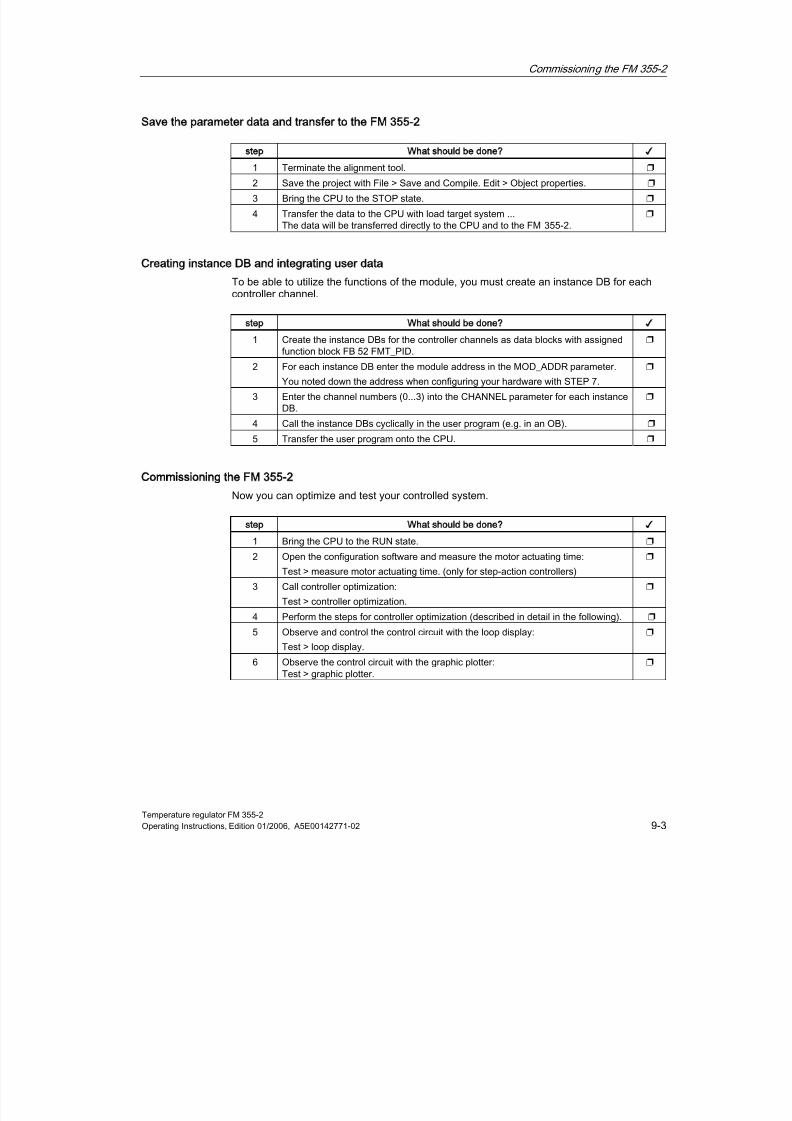
8/11/2019 FM_355-2_e
http://slidepdf.com/reader/full/fm355-2e 135/244
Commissioning the FM 355-2
Temperature regulator FM 355-2Operating Instructions, Edition 01/2006, A5E00142771-02 9-3
Save the parameter data and transfer to the FM 355-2
step What should be done? ✓
1 Terminate the alignment tool. ❐
2 Save the project with File > Save and Compile. Edit > Object properties. ❐
3 Bring the CPU to the STOP state. ❐
4 Transfer the data to the CPU with load target system ...The data will be transferred directly to the CPU and to the FM 355-2.
❐
Creating instance DB and integrating user data
To be able to utilize the functions of the module, you must create an instance DB for eachcontroller channel.
step What should be done? ✓
1 Create the instance DBs for the controller channels as data blocks with assignedfunction block FB 52 FMT_PID.
❐
2 For each instance DB enter the module address in the MOD_ADDR parameter.
You noted down the address when configuring your hardware with STEP 7.
❐
3 Enter the channel numbers (0...3) into the CHANNEL parameter for each instanceDB.
❐
4 Call the instance DBs cyclically in the user program (e.g. in an OB). ❐
5 Transfer the user program onto the CPU. ❐
Commissioning the FM 355-2
Now you can optimize and test your controlled system.
step What should be done? ✓
1 Bring the CPU to the RUN state. ❐
2 Open the configuration software and measure the motor actuating time:
Test > measure motor actuating time. (only for step-action controllers)
❐
3 Call controller optimization:
Test > controller optimization.
❐
4 Perform the steps for controller optimization (described in detail in the following). ❐
5 Observe and control the control circuit with the loop display:
Test > loop display.
❐
6 Observe the control circuit with the graphic plotter:Test > graphic plotter.
❐

8/11/2019 FM_355-2_e
http://slidepdf.com/reader/full/fm355-2e 136/244
Commissioning the FM 355-2
Temperature regulator FM 355-29-4 Operating Instructions, Edition 01/2006, A5E00142771-02
Controller optimization using the configuration software
step What should be done? ✓
1 Open the instance DB of the FMT_PID with Test > controller optimization. ❐
2 Check that manipulated variable and actual value are almost transient on thegraphic plotter and click on Continue.
❐
3 Set the "PID parameter" and click on Continue. ❐
4 Set "Optimize by approach to the operating point with setpoint step-change" andclick on Continue.
❐
5 Set the operating point to 90 and the manipulated variable difference to 80 andclick on Continue.
❐
6 If the end of controller optimization is signalized, click on Close. ❐
Now you can test the controller parameters found by feedforwarding a setpoint step-change
or a disturbance to the process.
Feedforwarding a setpoint step-change
step What should be done? ✓
1 Open the graphic plotter under menu item Test. ❐
2 Open the loop display screen form under menu item Test. ❐
3 Enter a setpoint step-change to 70 on the setpoint parameter and actuate theSend button.
❐
4 Observe the transient response of actual and manipulated variable. ❐
Feedforwarding a disturbance to the process
step What should be done? ✓
1 Open the VAT_Process variable table in the SIMATIC Manager ❐
2 Enter a process disturbance of 30 on the DISV parameter. ❐
3 Observe the transient response of actual and manipulated variable. ❐
Backup project
When you have completed all the tests successfully and the parameter settings of theFM 355-2 have been optimized, you must backup the data again.
step What should be done? ✓
1 Save all data in the configuration software with File > Save. ❐
2 Terminate the alignment tool. ❐
3 Save the program using HW Config with File > Save and Compile. ❐
4 Transfer the data to the CPU in the STOP state, load onto module with the targetsystem.
❐
5 Bring the CPU to the RUN state. ❐
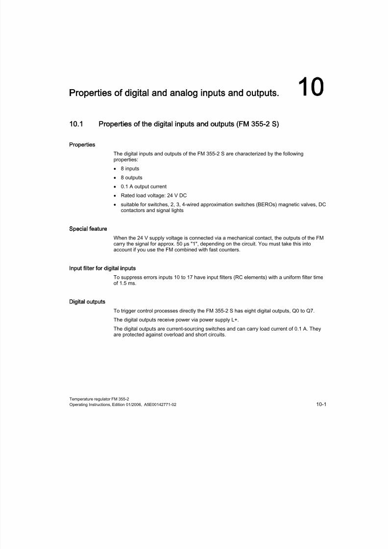
8/11/2019 FM_355-2_e
http://slidepdf.com/reader/full/fm355-2e 137/244
Temperature regulator FM 355-2Operating Instructions, Edition 01/2006, A5E00142771-02 10-1
Properties of digital and analog inputs and outputs.
10
10.1
101Properties of the digital inputs and outputs (FM 355-2 S)
Properties
The digital inputs and outputs of the FM 355-2 S are characterized by the followingproperties:
• 8 inputs
• 8 outputs
• 0.1 A output current
• Rated load voltage: 24 V DC
• suitable for switches, 2, 3, 4-wired approximation switches (BEROs) magnetic valves, DCcontactors and signal lights
Special feature
When the 24 V supply voltage is connected via a mechanical contact, the outputs of the FMcarry the signal for approx. 50 μs "1", depending on the circuit. You must take this intoaccount if you use the FM combined with fast counters.
Input filter for digital inputs
To suppress errors inputs 10 to 17 have input filters (RC elements) with a uniform filter timeof 1.5 ms.
Digital outputs
To trigger control processes directly the FM 355-2 S has eight digital outputs, Q0 to Q7.
The digital outputs receive power via power supply L+.
The digital outputs are current-sourcing switches and can carry load current of 0.1 A. Theyare protected against overload and short circuits.

8/11/2019 FM_355-2_e
http://slidepdf.com/reader/full/fm355-2e 138/244
Properties of digital and analog inputs and outputs.
10.1 Properties of the digital inputs and outputs (FM 355-2 S)
Temperature regulator FM 355-210-2 Operating Instructions, Edition 01/2006, A5E00142771-02
Terminal assignment and block diagram
Figure 10-1 Connection and block diagram of the digital inputs and outputs (FM 355-2 S)
The digital output LEDs are not controlled and are without significance.
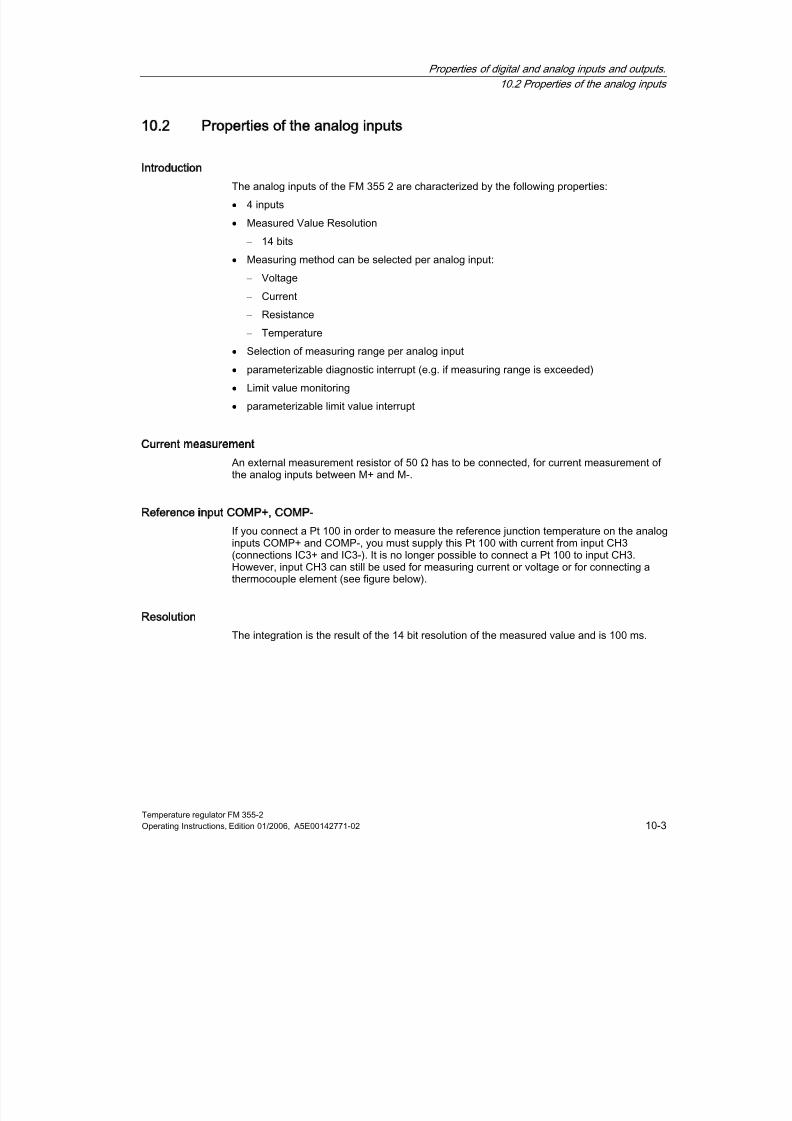
8/11/2019 FM_355-2_e
http://slidepdf.com/reader/full/fm355-2e 139/244
Properties of digital and analog inputs and outputs.
10.2 Properties of the analog inputs
Temperature regulator FM 355-2Operating Instructions, Edition 01/2006, A5E00142771-02 10-3
10.2
102
Properties of the analog inputs
Introduction
The analog inputs of the FM 355 2 are characterized by the following properties:
• 4 inputs
• Measured Value Resolution
– 14 bits
• Measuring method can be selected per analog input:
– Voltage
– Current
– Resistance – Temperature
• Selection of measuring range per analog input
• parameterizable diagnostic interrupt (e.g. if measuring range is exceeded)
• Limit value monitoring
• parameterizable limit value interrupt
Current measurement
An external measurement resistor of 50 Ω has to be connected, for current measurement of
the analog inputs between M+ and M-.
Reference input COMP+, COMP-
If you connect a Pt 100 in order to measure the reference junction temperature on the analoginputs COMP+ and COMP-, you must supply this Pt 100 with current from input CH3(connections IC3+ and IC3-). It is no longer possible to connect a Pt 100 to input CH3.However, input CH3 can still be used for measuring current or voltage or for connecting athermocouple element (see figure below).
Resolution
The integration is the result of the 14 bit resolution of the measured value and is 100 ms.

8/11/2019 FM_355-2_e
http://slidepdf.com/reader/full/fm355-2e 140/244
Properties of digital and analog inputs and outputs.
10.2 Properties of the analog inputs
Temperature regulator FM 355-210-4 Operating Instructions, Edition 01/2006, A5E00142771-02
Connection diagram
Figure 10-2 Connection diagram of the analog inputs

8/11/2019 FM_355-2_e
http://slidepdf.com/reader/full/fm355-2e 141/244
Properties of digital and analog inputs and outputs.
10.2 Properties of the analog inputs
Temperature regulator FM 355-2Operating Instructions, Edition 01/2006, A5E00142771-02 10-5
Block diagram
The figure below shows the block diagram of the analog inputs. The input resistance
depends on the set measuring range.
Figure 10-3 Block diagram of the analog inputs
See also
Basic structure of the FM 355-2 (Page 2-1)
Technical Specifications S7-300 (Page A-1)

8/11/2019 FM_355-2_e
http://slidepdf.com/reader/full/fm355-2e 142/244
Properties of digital and analog inputs and outputs.
10.3 Properties of the analog outputs (FM 355-2 C)
Temperature regulator FM 355-210-6 Operating Instructions, Edition 01/2006, A5E00142771-02
10.3
103
Properties of the analog outputs (FM 355-2 C)
Properties
The analog outputs of the FM 355 2 C are characterized by the following properties:
• 4 outputs
• the outputs can be selected channel by channel as
– Voltage output
– Current output
• Resolution 12 bits
• parameterizable diagnostic interrupt (short circuit, load break)
Note
When switching on/off the power supply (L+), incorrect intermediate values may appearon the output for approx. 10 ms.
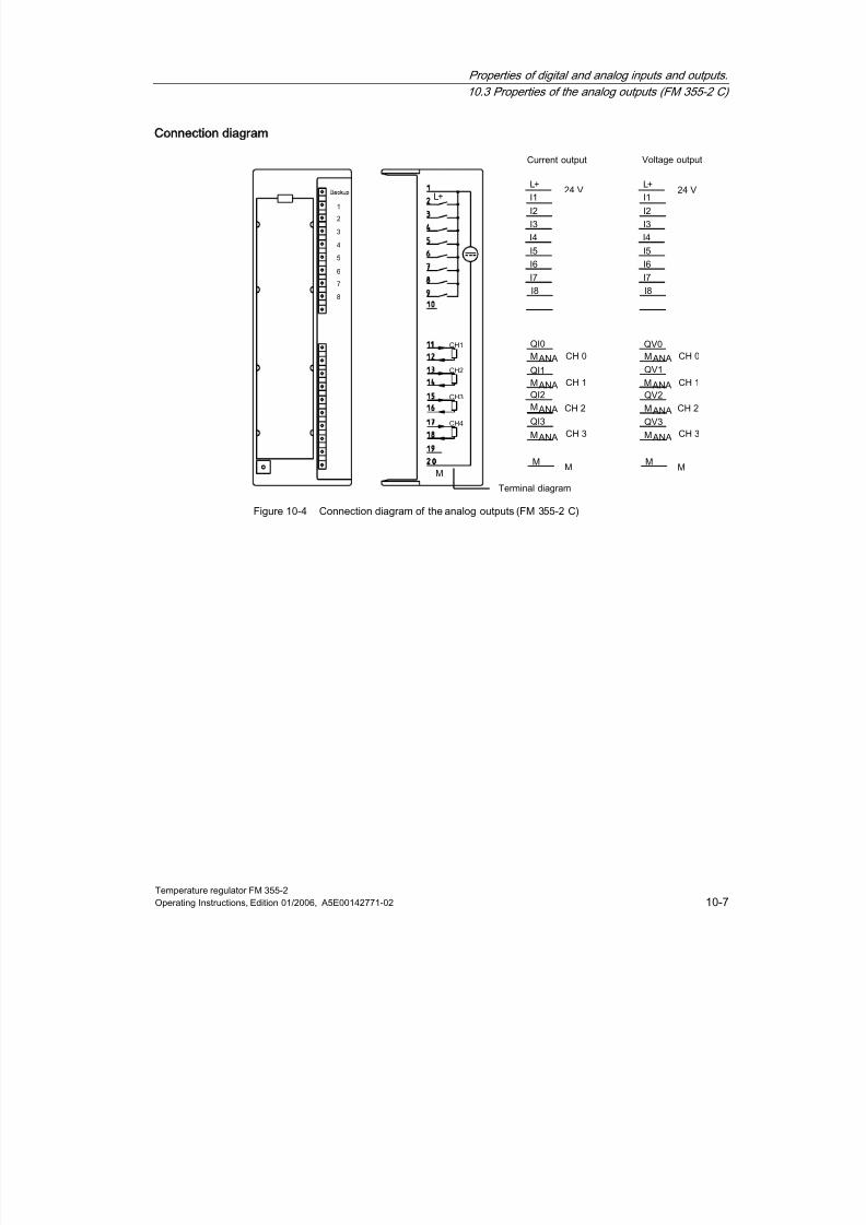
8/11/2019 FM_355-2_e
http://slidepdf.com/reader/full/fm355-2e 143/244
Properties of digital and analog inputs and outputs.
10.3 Properties of the analog outputs (FM 355-2 C)
Temperature regulator FM 355-2Operating Instructions, Edition 01/2006, A5E00142771-02 10-7
Connection diagram
Figure 10-4 Connection diagram of the analog outputs (FM 355-2 C)

8/11/2019 FM_355-2_e
http://slidepdf.com/reader/full/fm355-2e 144/244
Properties of digital and analog inputs and outputs.
10.3 Properties of the analog outputs (FM 355-2 C)
Temperature regulator FM 355-210-8 Operating Instructions, Edition 01/2006, A5E00142771-02
Block diagram
Figure 10-5 Block diagram of the analog outputs (FM 355-2 C)
See also
Basic structure of the FM 355-2 (Page 2-1)
8/11/2019 FM_355-2_e
http://slidepdf.com/reader/full/fm355-2e 145/244
Temperature regulator FM 355-2Operating Instructions, Edition 01/2006, A5E00142771-02 11-1
Connecting measuring transmitters and
actuators
11
11.1
111Connecting Loads/Actuators to Analog Outputs
Introduction
This module can be used to supply current or voltage to loads/actuators. The figure belowillustrates the principle.
Cables for analog signals
You should use shielded and twisted-pair cables for the analog signals. This reduces theeffect of interference. You should ground the shield of the analog cables at both ends of thecable. If there are differences in potential between the ends of the cables, equipotentialcurrent may flow across the shield, which could disturb the analog signals. If this is the case,you should only ground the shield at one end of the cable.
Reference Point M
ANA
When operating the module always interconnect the reference point MANA of the measuringcircuit with terminal M of the CPU. Connect the MANA terminal to the M terminal of the CPU.A difference in potential between MANA and the M connection of the CPU might give rise to acorruption of the analog signal.
Abbreviations Used
The abbreviations used in the figure below have the following meaning:
Q Analog output (current or voltage, depending on the configuration)MANA Reference potential of the analog circuit
RL: Load/Actuator
L+ Power supply 24 V DC
M Ground terminal

8/11/2019 FM_355-2_e
http://slidepdf.com/reader/full/fm355-2e 146/244
Connecting measuring transmitters and loads/actuators
11.1 Connecting Loads/Actuators to Analog Outputs
Temperature regulator FM 355-211-2 Operating Instructions, Edition 01/2006, A5E00142771-02
Connecting Loads to an Analog Output
Loads at an analog output have to be connected to Q and the reference point of the analogcircuit MANA.
Loads can only be connected to an analog output with a 2-wire connection.
The following figure illustrates the connection of loads to an analog output of the module.
Figure 11-1 Connection of a load to the module

8/11/2019 FM_355-2_e
http://slidepdf.com/reader/full/fm355-2e 147/244
Connecting measuring transmitters and loads/actuators
11.2 Connecting measuring transmitters to analog inputs
Temperature regulator FM 355-2Operating Instructions, Edition 01/2006, A5E00142771-02 11-3
11.2
112
Connecting measuring transmitters to analog inputs
Introduction
Depending on the measuring method, you can connect different measuring sensors to theanalog inputs of the FM 355-2:
• Voltage sensor
• Current sensors as 4-wire transducers and 2-wire transducers
• Resistance
This chapter describes how to connect the measuring transmitters and what you have towatch out for when connecting them.
Cables for analog signals
You should use shielded and twisted-pair cables for the analog signals. This reducesinterference. You should ground the analog cable shield at both ends of the cables. If thereare differences in potential between the ends of the cables, equipotential current may flowacross the shield, which could disturb the analog signals. In this event you should ground theshield at one end of the cable only.
Reference point M
ANA
In order to operate the FM 355-2 you must create a connection between the reference pointof the analog circuit MANA and the M connection of the CPU. A difference in potential
between MANA and the M connection of the CPU might give rise to a corruption of the analogsignal.
Abbreviations used
In both figures below the abbreviations used have the following meanings:
M+: Measuring cable (positive)
M– Measuring cable (negative)
MANA Reference potential of the analog measuring circuit
M Ground terminal
L+ Power supply 24 V DCUCM Potential difference between inputs and reference potential of the measuring
circuit MANA
Connecting measuring transmitters to analog inputs
No difference in potential ≥⃒U CM⃒ (Common Mode) may occur between the M- measuringcables of the input channels and the reference point of the measuring circuit MANA. Toprevent the permissible value from being exceeded, depending on the potential connectionof the encoder (isolated, not isolated), you must perform different actions.

8/11/2019 FM_355-2_e
http://slidepdf.com/reader/full/fm355-2e 148/244
Connecting measuring transmitters and loads/actuators
11.2 Connecting measuring transmitters to analog inputs
Temperature regulator FM 355-211-4 Operating Instructions, Edition 01/2006, A5E00142771-02
Isolated measuring sensor
The isolated measuring sensors are not connected to the local potential to ground. They can
be operated floating potential. Owing to local conditions or interference, differences inpotential UCM (static or dynamic) may occur between the M- measuring cables and thereference point of the measuring circuit MANA.
Note
To prevent the permissible value (UCM) from being exceeded you must connect M- to MANA.
Also when connecting resistance sensors, you must create a connection for M- to MANA. Thisalso applies to inputs with the corresponding parameter settings but which are unused.
Figure 11-2 Block diagram for connecting isolated measuring sensors

8/11/2019 FM_355-2_e
http://slidepdf.com/reader/full/fm355-2e 149/244
Connecting measuring transmitters and loads/actuators
11.2 Connecting measuring transmitters to analog inputs
Temperature regulator FM 355-2Operating Instructions, Edition 01/2006, A5E00142771-02 11-5
Non-isolated measuring sensors
The non-isolated measuring sensors are connected locally to the potential to ground. You
must connect MANA to the potential to ground. Owing to local conditions or interference,differences in potential UCM (static or dynamic) may occur between the locally distributedmeasuring points.
If the permissible value for UCM is exceeded, you must provide for potential-compensatingcables between the measuring points.
You must operate the CPU grounded, i.e. you must provide a bridge on the CPU betweenand M.
Figure 11-3 Block diagram for connecting non-isolated measuring sensors
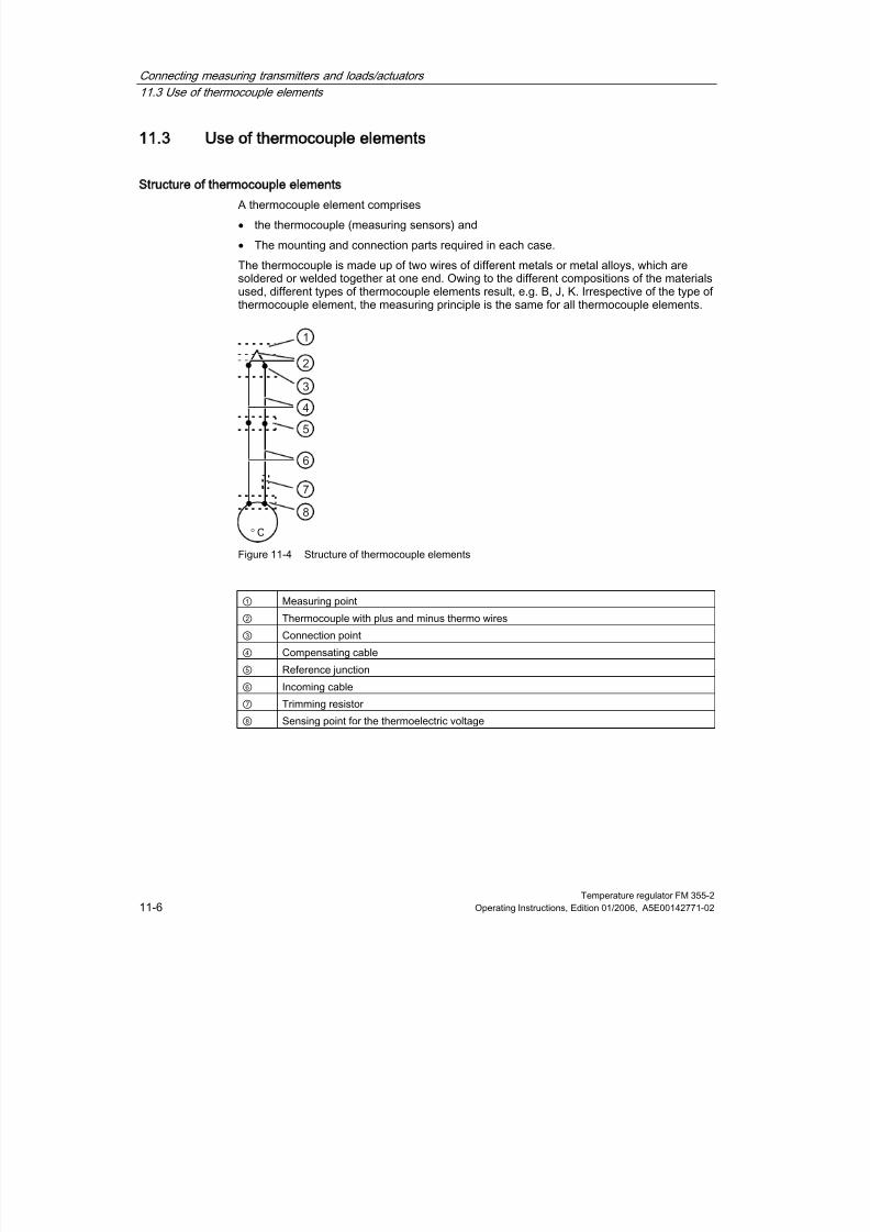
8/11/2019 FM_355-2_e
http://slidepdf.com/reader/full/fm355-2e 150/244
Connecting measuring transmitters and loads/actuators
11.3 Use of thermocouple elements
Temperature regulator FM 355-211-6 Operating Instructions, Edition 01/2006, A5E00142771-02
11.3
113
Use of thermocouple elements
Structure of thermocouple elements
A thermocouple element comprises
• the thermocouple (measuring sensors) and
• The mounting and connection parts required in each case.
The thermocouple is made up of two wires of different metals or metal alloys, which aresoldered or welded together at one end. Owing to the different compositions of the materialsused, different types of thermocouple elements result, e.g. B, J, K. Irrespective of the type ofthermocouple element, the measuring principle is the same for all thermocouple elements.
° C
Figure 11-4 Structure of thermocouple elements
① Measuring point
② Thermocouple with plus and minus thermo wires
③ Connection point
④ Compensating cable
⑤ Reference junction
⑥ Incoming cable⑦ Trimming resistor
⑧ Sensing point for the thermoelectric voltage

8/11/2019 FM_355-2_e
http://slidepdf.com/reader/full/fm355-2e 151/244

8/11/2019 FM_355-2_e
http://slidepdf.com/reader/full/fm355-2e 152/244
Connecting measuring transmitters and loads/actuators
11.3 Use of thermocouple elements
Temperature regulator FM 355-211-8 Operating Instructions, Edition 01/2006, A5E00142771-02
Use of thermocouple elements
When connecting thermocouple elements, you must take the following into account:
Depending on where you need the reference junction (locally), you can work with aconfigured or an external compensation.
If a configured compensation is used, a configurable reference point temperature of themodule is used for comparison.
With an external compensation the temperature of the reference junction of thethermocouple elements is taken into account by using a Pt 100.
This Pt 100 is connected to terminals 10 and 11 on the left-hand front connector of themodule, whereby the Pt 100 must be located at the reference junction of the thermocoupleelements. You must take its power supply from Channel 2 (terminals 12 and 13 of the left-hand front connector).
The following restriction applies:
• External compensation with the Pt 100 connected to terminals 10 and 11 of the modulecan only be carried out for one type of thermocouple element. This means that allchannels operating with external compensation must use the same type.
Abbreviations used
In both figures below the abbreviations used have the following meanings:
M+ Measuring cable (positive)
M– Measuring cable (negative)
COMP+ Compensation connection (positive)
COMP– Compensation connection (negative)
M Ground terminal
L+ Power supply 24 V DC
Options for connecting thermocouple elements
The figures below show the various possible connections for thermocouple elements withexternal and configured compensation.
In addition to the following statements, the information from chapter "Connecting measuringsensors to analog inputs" also applies. The following figures do not contain the necessary
connecting cables between the M terminal of the CPU, M-, MANA and ground potential, thatresult from the potential bonding of the FM 355-2 and the transducers (isolated, non-isolated). This means that you must continue to pay heed to the statements made in thechapter "Connecting measuring sensors to analog inputs" and implement them.

8/11/2019 FM_355-2_e
http://slidepdf.com/reader/full/fm355-2e 153/244
Connecting measuring transmitters and loads/actuators
11.3 Use of thermocouple elements
Temperature regulator FM 355-2Operating Instructions, Edition 01/2006, A5E00142771-02 11-9
Thermocouple elements with external compensation of the reference junction
If all thermocouple elements connected to the inputs of the FM 355-2 have the same
reference junction, you compensate as shown in the figure below. Thermocouple elementsusing the same reference junction must be of the same type.
Figure 11-5 Block diagram for connecting thermocouple elements with external compensation

8/11/2019 FM_355-2_e
http://slidepdf.com/reader/full/fm355-2e 154/244
Connecting measuring transmitters and loads/actuators
11.3 Use of thermocouple elements
Temperature regulator FM 355-211-10 Operating Instructions, Edition 01/2006, A5E00142771-02
Thermocouple elements with configured or internal compensation of the reference junction
If thermocouple elements are connected directly to the inputs of the module by means of
compensation cables, the configured or internal temperature compensation can be used.The figures above show how to connect the thermocouple elements to ground.
Figure 11-6 Block diagram for connecting thermocouple elements with configured or internal
compensation

8/11/2019 FM_355-2_e
http://slidepdf.com/reader/full/fm355-2e 155/244
Connecting measuring transmitters and loads/actuators
11.4 Connecting voltage and current transducers with resistance thermometers
Temperature regulator FM 355-2Operating Instructions, Edition 01/2006, A5E00142771-02 11-11
11.4
114
Connecting voltage and current transducers with resistance
thermometers
Abbreviations used
In both figures below the abbreviations used have the following meanings:
I+ Constant current cable (positive)
I– Constant current cable (negative)
M+: Measuring cable (positive)
M– Measuring cable (negative)
MANA Reference potential of the analog measuring circuit
M Connection to groundL+ 24V DC voltage supply
In addition to the following statements, the above information on "Connecting measuringsensors to analog inputs" also applies.
The following figures do not contain the necessary connecting cables between the Mterminal of the CPU, M-, MANAand ground potential, that result from the potential bonding ofthe FM 355-2 and the transducers (isolated, non-isolated).This means that you mustcontinue to pay heed to the statements made in the section on "Connecting measuringsensors to analog inputs" and implement them.
Connecting voltage transducers
Figure 11-7 Connecting voltage transducers
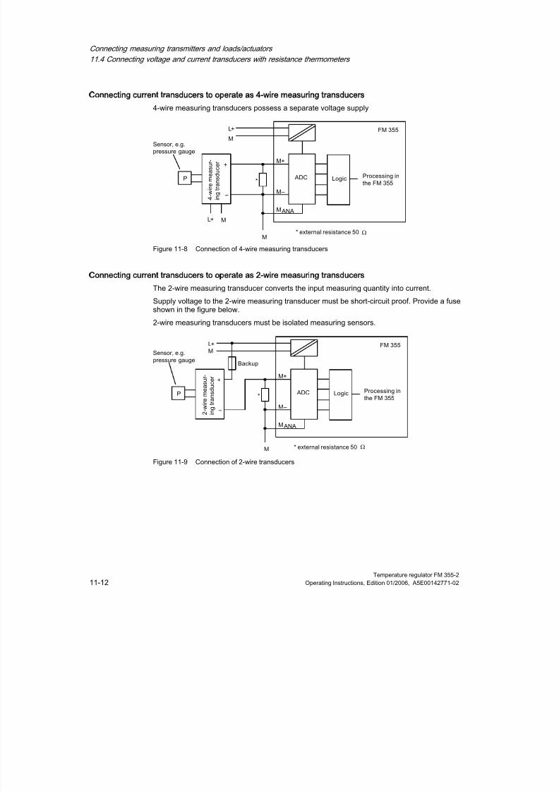
8/11/2019 FM_355-2_e
http://slidepdf.com/reader/full/fm355-2e 156/244
Connecting measuring transmitters and loads/actuators
11.4 Connecting voltage and current transducers with resistance thermometers
Temperature regulator FM 355-211-12 Operating Instructions, Edition 01/2006, A5E00142771-02
Connecting current transducers to operate as 4-wire measuring transducers
4-wire measuring transducers possess a separate voltage supply
Figure 11-8 Connection of 4-wire measuring transducers
Connecting current transducers to operate as 2-wire measuring transducers
The 2-wire measuring transducer converts the input measuring quantity into current.
Supply voltage to the 2-wire measuring transducer must be short-circuit proof. Provide a fuseshown in the figure below.
2-wire measuring transducers must be isolated measuring sensors.
Figure 11-9 Connection of 2-wire transducers
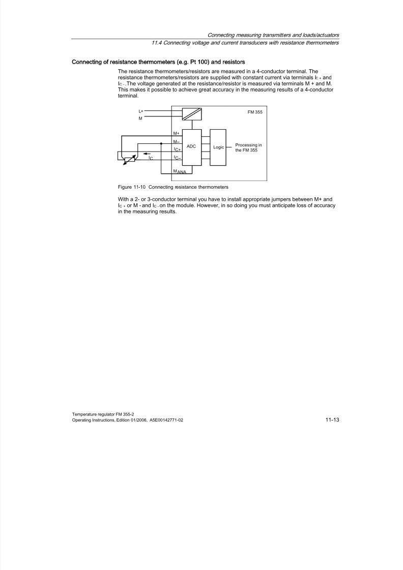
8/11/2019 FM_355-2_e
http://slidepdf.com/reader/full/fm355-2e 157/244
Connecting measuring transmitters and loads/actuators
11.4 Connecting voltage and current transducers with resistance thermometers
Temperature regulator FM 355-2Operating Instructions, Edition 01/2006, A5E00142771-02 11-13
Connecting of resistance thermometers (e.g. Pt 100) and resistors
The resistance thermometers/resistors are measured in a 4-conductor terminal. The
resistance thermometers/resistors are supplied with constant current via terminals IC + andIC - .The voltage generated at the resistance/resistor is measured via terminals M + and M.This makes it possible to achieve great accuracy in the measuring results of a 4-conductorterminal.
Figure 11-10 Connecting resistance thermometers
With a 2- or 3-conductor terminal you have to install appropriate jumpers between M+ andIC + or M - and IC - on the module. However, in so doing you must anticipate loss of accuracyin the measuring results.

8/11/2019 FM_355-2_e
http://slidepdf.com/reader/full/fm355-2e 158/244
Connecting measuring transmitters and loads/actuators
11.5 Connecting loads/actuators to digital outputs
Temperature regulator FM 355-211-14 Operating Instructions, Edition 01/2006, A5E00142771-02
11.5
115
Connecting loads/actuators to digital outputs
Introduction
The FM 355-2 S enables you to supply loads/actuators with voltage.
Abbreviations used
the abbreviations used have the following meanings:
Q Digital output
RL Load/actuator
L+ 24V DC voltage supply
M Connection to ground
Connecting loads/actuators to an analog output
Figure 11-11 Connecting loads/actuators to an FM 355-2 S
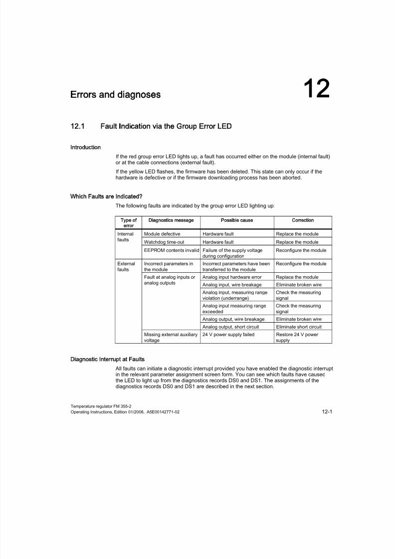
8/11/2019 FM_355-2_e
http://slidepdf.com/reader/full/fm355-2e 159/244
Temperature regulator FM 355-2Operating Instructions, Edition 01/2006, A5E00142771-02 12-1
Errors and diagnoses
12
12.1
121Fault Indication via the Group Error LED
Introduction
If the red group error LED lights up, a fault has occurred either on the module (internal fault)or at the cable connections (external fault).
If the yellow LED flashes, the firmware has been deleted. This state can only occur if thehardware is defective or if the firmware downloading process has been aborted.
Which Faults are Indicated?
The following faults are indicated by the group error LED lighting up:
Type of
error
Diagnostics message Possible cause Correction
Module defective Hardware fault Replace the moduleWatchdog time-out Hardware fault Replace the module
Internalfaults
EEPROM contents invalid Failure of the supply voltageduring configuration
Reconfigure the module
Incorrect parameters inthe module
Incorrect parameters have beentransferred to the module
Reconfigure the module
Analog input hardware error Replace the module
Analog input, wire breakage Eliminate broken wire
Analog input, measuring rangeviolation (underrange)
Check the measuringsignal
Analog input measuring range
exceeded
Check the measuring
signalAnalog output, wire breakage Eliminate broken wire
Fault at analog inputs oranalog outputs
Analog output, short circuit Eliminate short circuit
Externalfaults
Missing external auxiliaryvoltage
24 V power supply failed Restore 24 V powersupply
Diagnostic Interrupt at Faults
All faults can initiate a diagnostic interrupt provided you have enabled the diagnostic interruptin the relevant parameter assignment screen form. You can see which faults have causedthe LED to light up from the diagnostics records DS0 and DS1. The assignments of thediagnostics records DS0 and DS1 are described in the next section.
8/11/2019 FM_355-2_e
http://slidepdf.com/reader/full/fm355-2e 160/244
Errors and diagnoses
12.2 Triggering diagnostic interrupts
Temperature regulator FM 355-212-2 Operating Instructions, Edition 01/2006, A5E00142771-02
12.2
122
Triggering diagnostic interrupts
What is a diagnostic interrupt?
If the user program is to react to an internal fault or external error, you can configure adiagnostic interrupt. The cyclical CPU program is interrupted and the diagnostic interrupt OB,OB 82 is called.
Which events may trigger a diagnostic interrupt?
The list shows you which events can trigger a diagnostic interrupt:
• Module configuration missing or faulty
• Module defective
• Wire break when analog inputs are made (4 up to 20 mA only)
• Overflow and underflow during analog inputs
• Load break or short-circuit during analog outputs
Enabling the diagnostic interrupt
You can enable or disable the diagnostic interrupt for the module in the basic parameter tab.
The default setting for the diagnostic interrupt is disabled.
Reactions to an event triggering an interrupt
If an event occurs that can trigger a diagnostic interrupt, the following occurs:
• The diagnostics information is written to the diagnostics data records DS0 and DS1 onthe module.
• The group error LED lights up.
• Diagnostic interrupt OB is called (OB 82).
• Diagnostic data record DS0 is written to the start information of diagnostic interrupt OB.
• If there is no hardware defect, the module resumes control operation.
If no OB 82 is programmed, the CPU goes into STOP.
Diagnostics data record DS0 and DS1
The information about which event triggered a diagnostic interrupt is written to the diagnosticdata records DS0 and DS1. The length of the diagnostic data record DS0 is four bytes; therecord length of DS1 is 16 bytes of which the first 4 bytes are identical with DS0.
8/11/2019 FM_355-2_e
http://slidepdf.com/reader/full/fm355-2e 161/244
Errors and diagnoses
12.3 Diagnostics data records DS0 and DS1
Temperature regulator FM 355-2Operating Instructions, Edition 01/2006, A5E00142771-02 12-3
12.3
123
Diagnostics data records DS0 and DS1
Reading a data record from the module
Diagnostic data record DS0 is automatically transferred to the start information when thediagnostic OBs are called. These four bytes are written to the local date (bytes 8-11) of theOB 82.
You can fetch diagnostic data record DS1 (and hence also the content of DS0) from themodule by means of the FB 55 FMT_DS1. This only makes sense if an error is reported in achannel in the DS0.
The FB 55 FMT_DS1 must be called in the same OB as an FB FMT_PID that might bepresent (e.g. OB 35). You can do this as follows: While OB 82 is being processed, set theREAD_DS1 bit. The FMT_DS1 in OB 35 then reads the diagnostic data record DS1.
How does the diagnosis text appear in the diagnostics buffer?
To enter the diagnostic message in the diagnostics buffer you must call the SFC 52 "Writeuser-specific message to diagnostics buffer" in the user program. The event number of therespective diagnosis message is specified on the input parameter EVENTN. The interrupt isentered in the diagnostics buffer defined as x = 1 for incoming and x = 0 for outgoing. Inaddition to the time of the entry, the appropriate diagnosis text is displayed in the "Meaning"column.
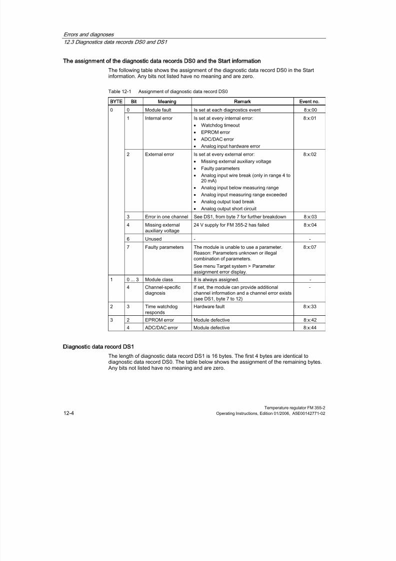
8/11/2019 FM_355-2_e
http://slidepdf.com/reader/full/fm355-2e 162/244
Errors and diagnoses
12.3 Diagnostics data records DS0 and DS1
Temperature regulator FM 355-212-4 Operating Instructions, Edition 01/2006, A5E00142771-02
The assignment of the diagnostic data records DS0 and the Start information
The following table shows the assignment of the diagnostic data record DS0 in the Start
information. Any bits not listed have no meaning and are zero.
Table 12-1 Assignment of diagnostic data record DS0
BYTE Bit Meaning Remark Event no.
0 Module fault Is set at each diagnostics event 8:x:00
1 Internal error Is set at every internal error:
•
Watchdog timeout
•
EPROM error
•
ADC/DAC error
•
Analog input hardware error
8:x:01
2 External error Is set at every external error:
•
Missing external auxiliary voltage
•
Faulty parameters
•
Analog input wire break (only in range 4 to20 mA)
•
Analog input below measuring range
•
Analog input measuring range exceeded
•
Analog output load break
•
Analog output short circuit
8:x:02
3 Error in one channel See DS1, from byte 7 for further breakdown 8:x:03
4 Missing externalauxiliary voltage
24 V supply for FM 355-2 has failed 8:x:04
6 Unused - -
0
7 Faulty parameters The module is unable to use a parameter.Reason: Parameters unknown or illegalcombination of parameters.
See menu Target system > Parameterassignment error display.
8:x:07
0 ... 3 Module class 8 is always assigned. -1
4 Channel-specificdiagnosis
If set, the module can provide additionalchannel information and a channel error exists(see DS1, byte 7 to 12)
-
2 3 Time watchdog
responds
Hardware fault 8:x:33
2 EPROM error Module defective 8:x:423
4 ADC/DAC error Module defective 8:x:44
Diagnostic data record DS1
The length of diagnostic data record DS1 is 16 bytes. The first 4 bytes are identical todiagnostic data record DS0. The table below shows the assignment of the remaining bytes.Any bits not listed have no meaning and are zero.

8/11/2019 FM_355-2_e
http://slidepdf.com/reader/full/fm355-2e 163/244
Errors and diagnoses
12.3 Diagnostics data records DS0 and DS1
Temperature regulator FM 355-2Operating Instructions, Edition 01/2006, A5E00142771-02 12-5
Diagnostic data record DS1 of the FM 355-2
Table 12-2 Assignments of bytes 4 to 12 of diagnostic data record DS1 of the FM 355-2BYTE Bit Meaning Remark Event no.
4 0 ... 7 Channel type 75H is always assigned. -
5 0 ... 7 Length of the diagnosticsinformation
8 is always assigned. -
6 0 ... 7 Number of channels 5 always assigned (4 controllers + 1reference channel)
-
7 0 ... 4 Channel error vector 1 bit is assigned to each channel(0...3; 4 for reference channel).
-
0 Analog input hardware error 8:x:B0
1 Unused 8:x:B1
2 Analog input wire break (onlyin range 4 to 20 mA)
8:x:B2
3 Unused 8:x:B3
4 Analog input belowmeasuring range
8:x:B4
5 Analog input measuring rangeexceeded
8:x:B5
6 Analog output wire breakage Only with thecurrent output ofthe C controller
8:x:B6
8
7 Analog output short circuit
Channel-specificdiagnosticschannel 0
Only with thevoltage output of
theC controller
8:x:B7
9 0 ... 7 see byte 8 Channel-specific diagnostics channel1
See above
10 0 ... 7 see byte 8 Channel-specific diagnostics channel2
See above
11 0 ... 7 see byte 8 Channel-specific diagnostics channel3
See above
12 0 ... 5 see byte 8 Diagnostics for reference channel See above

8/11/2019 FM_355-2_e
http://slidepdf.com/reader/full/fm355-2e 164/244
Errors and diagnoses
12.4 Measuring transducer fault
Temperature regulator FM 355-212-6 Operating Instructions, Edition 01/2006, A5E00142771-02
12.4
124
Measuring transducer fault
Measuring transducer faults
The FM 355-2 can identify the following measuring transducer faults:
• Measuring range violation (underrange)
• Measuring range violation (overrange)
• Wire break (not for all measuring ranges)
If one of these faults occur, the group error bit "external error" is set in diagnostic data recordDS0 and channel-specific error bits are set in diagnostic data record DS1 (see table above).Once these faults disappear, the respective bits are reset.
The following table shows the specific measuring range limits at which the error bits are set
or reset:
Error bit measuring range
violation (underrange)
at...
Error bit measuring range
violation (overrange) at...
Error bit wire break
display
Measuring range
DS1: Byte 10 to 26, bit 4 DS1: Byte 10 to 26, bit 5 DS1: Byte 10 to 26, bit 2
0 to 20 mA < - 3.5 mA > 23.5 mA -
4 to 20 mA Error bit = 1 at < 3.6 mA
Error bit = 0 at < 3.8 mA
> 22.8 mA Error bit = 1 at < 3.6 mA
Error bit = 0 at < 3.8 mA
0 to 10 V <- 1.175 V > 11.75 V -
Pt 100
(-200 to 850 °C)(-328 to 1562 °F)
< 30.82 mV > 650.46 mV -
Pt 100
(-200 to 556 ーC)
(-328 to 1032 °F)
< 30.82 mV > 499.06 mV -
Pt 100
(-200 to 130 °C)
(-328 to 264 °F)
< 30.82 mV > 254.12 mV -
Type Bthermocoupleelement
< 0 mV > 13.81 mV -
Type Ethermocoupleelement
(-270.0 to1,000.03 °C)
< -9.84 mV > 76.36 mV -
Type Jthermocoupleelement
< -8.1 mV > 69.54 mV -

8/11/2019 FM_355-2_e
http://slidepdf.com/reader/full/fm355-2e 165/244
Errors and diagnoses
12.4 Measuring transducer fault
Temperature regulator FM 355-2Operating Instructions, Edition 01/2006, A5E00142771-02 12-7
Error bit measuring range
violation (underrange)
at...
Error bit measuring range
violation (overrange) at...
Error bit wire break
display
Type Kthermocoupleelement
< -6.45 mV > 54.88 mV -
Type Rthermocoupleelement
< -0.23 mV > 21.11 mV -
Type Sthermocoupleelement
< -0.24 mV > 18.7 mV -
Freethermocoupleelement
< lower input value of thepolyline
> upper input value of thepolyline
-

8/11/2019 FM_355-2_e
http://slidepdf.com/reader/full/fm355-2e 166/244
Errors and diagnoses
12.4 Measuring transducer fault
Temperature regulator FM 355-212-8 Operating Instructions, Edition 01/2006, A5E00142771-02

8/11/2019 FM_355-2_e
http://slidepdf.com/reader/full/fm355-2e 167/244
Temperature regulator FM 355-2Operating Instructions, Edition 01/2006, A5E00142771-02 13-1
Examples
13
13.1
131Introduction
Prerequisites
• You have set up and wired an S7 station consisting of a power supply module and aCPU.
• STEP 7 (>= V5.1 SP4) is installed on your programming device or PC.
• Your programming device or PC is connected to the CPU.
• The CPU and FM 355-2 are supplied with voltage
Preparations for the examples
1. With SIMATIC Manager open the zDt28_01_FMTemp sample project in the...\STEP7\EXAMPLES directory and copy it into your project directory using anappropriate name (File > Save as). Use the View > detail display for full information.
2. Create a new project.
3.
Select one of the temperature samples and copy it into your project (including hardware).4. Adapt the hardware (if necessary replace the CPU).
5. Configure the hardware with HW Config (set time interrupt OB).
6. Save the hardware configuration and download it to the CPU.
7. Download the block folder to the CPU.
Sample code
The samples are written in STL. You can view them directly via the KOP/AWL/FUP Editor. Inthis editor select via View > Displays with "Symbolic view", "Symbol selection" and"Comments" If you have sufficient space on the screen you can also have the "symbol
information" displayed.
Sample application
The sample programs contain variable tables (VAT) with which you can view and change thevalues. You can view curve traces using the graphic plotter in the configuration software.
Further use of a sample
The sample code has not been optimized and is not designed for all eventualities.
In order to keep the size of the programs down, error evaluation has not been programmedin detail in the example programs.

8/11/2019 FM_355-2_e
http://slidepdf.com/reader/full/fm355-2e 168/244

8/11/2019 FM_355-2_e
http://slidepdf.com/reader/full/fm355-2e 169/244
Examples
13.2 Sample application for FM 355-2 C (closed-loop controller)
Temperature regulator FM 355-2Operating Instructions, Edition 01/2006, A5E00142771-02 13-3
Functions of the example program
Essentially, the example comprises the two function blocks FMT_PID (FB 52) and
PROC_HCC (FB 100). Here PROC_HCC simulates the control process with third ordercompensation. The FB FMT_PV (FB 57) transfers the process values to the FM.
Figure 13-1 Example 355-2 C, control loop
Function block PROC_HCC simulates a series circuit comprising three lag elements of thefirst order (figure below). The disturbance variable DISV is always added to the output signalof the lag element enabling process disturbances to be activated manually at this point. Thestatic process gain can be set via the GAIN factor.
The process structure is set up twice to implement an additional cooling section.
When initializing COM_RST = TRUE the output variable of the simulated control process isset to OUTV = (INV_HEAT+DISV_H) * GAIN_H - (INV_COOL+DISV_C) * GAIN_C + AMB_TEM.
Figure 13-2 Structure and parameters of the process block PROC_HCC

8/11/2019 FM_355-2_e
http://slidepdf.com/reader/full/fm355-2e 170/244
Examples
13.2 Sample application for FM 355-2 C (closed-loop controller)
Temperature regulator FM 355-213-4 Operating Instructions, Edition 01/2006, A5E00142771-02
Block structure
Table 13-1 Blocks of example
Block Name
(in toolbar)
Description
OB 100 COMPLETE_RESTART Restart OB
OB 35 CYC_INT5 time-controlled OB (100 ms) with example
FB 52 FMT_PID closed-loop controller FM 355-2 C
FB 57 FMT_PV Process value transfer to FM 355-2 C
FB 100 PROC_HCC Process for closed-loop controllers
DB 52 DB_FMT_PID Instance DB to FMT_PID
DB 57 DB_FMT_PV Instance DB to FMT_PV
DB 100 DB_PROC_HCC Instance DB to PROC_HCC
Parameter optimization and simulation
A practical configuration of a closed-loop controller with PID action shows you the responseof a control loop with a simulated PT control system of the second order. The set processparameters represent an approximation of the behavior of a fast temperature process.
The following table contains the currently set values of the relevant parameters relevant tocontroller 0 and process.
Parameters Type Parameter settings Description
Controller:
GAIN REAL 12.0 P-action coefficient
TI REAL 12.0s Integration time
TD REAL 3.0s Derivative action time
PFAC_SP REAL 0.8 Proportional factor
RATIOFAC REAL 0.5 Ratio factor
CON_ZONE REAL 31.0 Control zone width
Control system:
CYCLE REAL 100 ms Scan time
GAIN_H REAL 1.5 Heating process gain
TMLAG1_H REAL 60s Heating time lag 1
TMLAG2_H REAL 10s Heating time lag 2
TMLAG3_H REAL 0s Heating time lag 3
GAIN_C REAL 3.0 Cooling process gain
TMLAG1_C REAL 60s Cooling time lag 1
TMLAG2_C REAL 10s Cooling time lag 2
TMLAG3_C REAL 0s Cooling time lag 3
The controller parameters above were determined in an optimization process (TUN_DLMN =80.0 and setpoint step change from 0 to 90). You should now perform optimization.
8/11/2019 FM_355-2_e
http://slidepdf.com/reader/full/fm355-2e 171/244
Examples
13.2 Sample application for FM 355-2 C (closed-loop controller)
Temperature regulator FM 355-2Operating Instructions, Edition 01/2006, A5E00142771-02 13-5
After you have optimized heating, optimize cooling using the new setpoint value(TUN_CLMN = -20.0).
Note
Each time you perform optimization you will obtain slightly different values for the controllerparameters. This is because the time cycle of the time watchdog OBs (e.g. 100 ms) and theFM 355-2 cycle time (e.g. 100.5 ms) never match exactly.Hence, the process model on theCPU does not supply not return a smooth actual value process for the optimization on theFM 355-2.
Thereafter you can test the control response by means of set point step change andactivating disturbances (parameter DISV_H/C at DB_PROC_HCC). Also test the effect of the
PFAC_SP parameter: If, for example, you raise PFAC_SP from 0.8 to 1.0, this will alsoincrease overshoot.
Please remember to set LOAD_PAR = TRUE if you want to change parameters via the FMT-PID.
Note
With the control zone enabled (CONZ_ON = TRUE) test the control action with setpoint stepchanges > CON_ZONE (or < -CON_ZONE/RATIOFAC for negative setpoint step changes).In this case PFAC_SP has no effect.

8/11/2019 FM_355-2_e
http://slidepdf.com/reader/full/fm355-2e 172/244
Examples
13.3 Application example for the FM 355-2 S (pulse controller)
Temperature regulator FM 355-213-6 Operating Instructions, Edition 01/2006, A5E00142771-02
13.3
133
Application example for the FM 355-2 S (pulse controller)
Introduction
In project file zDt28_01_FMTemp you will find the example "Pulse controller FM 355-2 S",which makes it possible to operate the FM 355-2 S on the CPU simulation processes. Thismakes it possible to test the module without a real process.
Load the sample program
To install the program, proceed as follows:
1. Download the configuration to the CPU.
2. Start the "HW Config program: Configure hardware”, start the FM 355-2 parameter
assignment application.3. In order to enable work with the loop display, the graphic plotter and the controller tuning,
with menu item Test > ...> instance DB, launch the DB 52.
Sample program application
The sample contains a pulse controller (three-component controller), in conjunction with asimulated control system consisting of two lag elements of the third order (PT3) for heatingand cooling.
With the help of this sample program, you can easily generate a closed-loop PID controllerand configure and test all properties of this controller offline in a typical process.
The sample program helps you to understand the operation and configuration of controllerswith pulse output and the way they are used to control processes with binary inputs. Hence,the sample is also suitable for system introduction and training courses.
Appropriate selection of parameters gives you a process that represents an approximation ofthe real process. You can use the controller tuning feature to determine a controllerparameter record to match your process model.
In the sample we shall call FB FMT_PID with READ_OUT = TRUE, to ensure that the pulsesQLMNUP and QLMNDN affect every cycle of the process model in the CPU. This would notbe ensured with direct I/O access. When used in a real process, there is no need to setREAD_OUT = TRUE periodically.

8/11/2019 FM_355-2_e
http://slidepdf.com/reader/full/fm355-2e 173/244
Examples
13.3 Application example for the FM 355-2 S (pulse controller)
Temperature regulator FM 355-2Operating Instructions, Edition 01/2006, A5E00142771-02 13-7
Sample program functions
The sample primarily consists of the two function blocks FMT_PID (FB 52) and PROC_HCP
(FB 102). PROC_HCP simulates a control system with a compensation element of the thirdorder. FB FMT_PV (FB 57) transfers the actual values in the FM.
Figure 13-3 Sample application for FM 355-2 S, closed-loop controller
Function block PROC_HCP forms an image of a heating/cooling process with binary inputs(see illustration below). The binary input signals are converted into continuous floating-pointvalues (0.0 or 100.0). After the activation of the disturbance variable and multiplication by theprocess gain value, the actual values are passed through three lag elements of the firstorder. This procedure is performed separately in the heating and cooling process. Finally,the value of the ambient temperature is added.
When initialized with COM_RST = TRUE, the output variable of the simulated process is setto the value OUTV = DISV_H * GAIN_H - DISV_C * GAIN_C + AMB_TEM.
Figure 13-4 Structure and parameters of the process module PROC_HCP
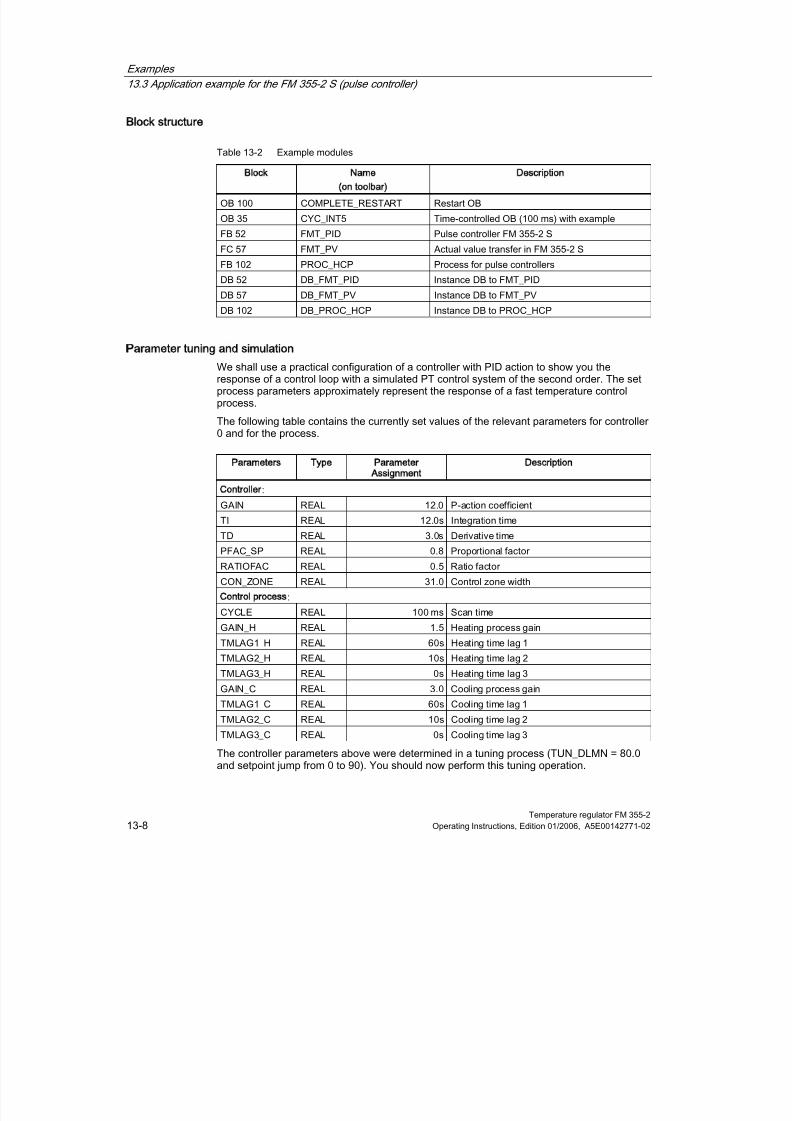
8/11/2019 FM_355-2_e
http://slidepdf.com/reader/full/fm355-2e 174/244
Examples
13.3 Application example for the FM 355-2 S (pulse controller)
Temperature regulator FM 355-213-8 Operating Instructions, Edition 01/2006, A5E00142771-02
Block structure
Table 13-2 Example modulesBlock Name
(on toolbar)
Description
OB 100 COMPLETE_RESTART Restart OB
OB 35 CYC_INT5 Time-controlled OB (100 ms) with example
FB 52 FMT_PID Pulse controller FM 355-2 S
FC 57 FMT_PV Actual value transfer in FM 355-2 S
FB 102 PROC_HCP Process for pulse controllers
DB 52 DB_FMT_PID Instance DB to FMT_PID
DB 57 DB_FMT_PV Instance DB to FMT_PV
DB 102 DB_PROC_HCP Instance DB to PROC_HCP
Parameter tuning and simulation
We shall use a practical configuration of a controller with PID action to show you theresponse of a control loop with a simulated PT control system of the second order. The setprocess parameters approximately represent the response of a fast temperature controlprocess.
The following table contains the currently set values of the relevant parameters for controller0 and for the process.
Parameters Type Parameter
Assignment
Description
Controller
:
GAIN REAL 12.0 P-action coefficient
TI REAL 12.0s Integration time
TD REAL 3.0s Derivative time
PFAC_SP REAL 0.8 Proportional factor
RATIOFAC REAL 0.5 Ratio factor
CON_ZONE REAL 31.0 Control zone width
Control process:
CYCLE REAL 100 ms Scan time
GAIN_H REAL 1.5 Heating process gainTMLAG1_H REAL 60s Heating time lag 1
TMLAG2_H REAL 10s Heating time lag 2
TMLAG3_H REAL 0s Heating time lag 3
GAIN_C REAL 3.0 Cooling process gain
TMLAG1_C REAL 60s Cooling time lag 1
TMLAG2_C REAL 10s Cooling time lag 2
TMLAG3_C REAL 0s Cooling time lag 3
The controller parameters above were determined in a tuning process (TUN_DLMN = 80.0and setpoint jump from 0 to 90). You should now perform this tuning operation.

8/11/2019 FM_355-2_e
http://slidepdf.com/reader/full/fm355-2e 175/244
Examples
13.3 Application example for the FM 355-2 S (pulse controller)
Temperature regulator FM 355-2Operating Instructions, Edition 01/2006, A5E00142771-02 13-9
After you have tuned heating, tune the cooling using the new setpoint value(TUN_CLMN = -20.0).
Note
Every time you perform a tuning operation, you will receive slightly different parametervalues for the controller. The reason is that the clock cycle of the watchdog interrupt OBs(e.g. 100 ms) and the cycle time of the FM 355-2 (e.g. 100.5 ms) never match completely.This is why the process model in the CPU does not return a smooth process variable foryour tuning operations on the FM 355-2.
You can subsequently activate setpoint jumps and disturbance variables to test controlresponse (Parameter DISV at DB_PROC_HCP). Also test the effect of parameter PFAC_SP:
For example, when you increase the value in PFAC_SP from 0.8 to 1.0, you will likewiseincrease overshoot.
Please note that you must also set LOAD_PAR = TRUE when you modify parameters viaFMT_PID.
Note
With enabled control zone (CONZ_ON = TRUE), activate setpoint jumps > CON_ZONE(or < -CON_ZONE/RATIOFAC for negative setpoint jumps) to test control response. In thiscase PFAC_SP has no effect.

8/11/2019 FM_355-2_e
http://slidepdf.com/reader/full/fm355-2e 176/244
Examples
13.4 Application example for the FM 355-2 S (step controller)
Temperature regulator FM 355-213-10 Operating Instructions, Edition 01/2006, A5E00142771-02
13.4
134
Application example for the FM 355-2 S (step controller)
Introduction
In project file zDt28_01_FMTemp you will find the example "Step controller FM 355-2 S",which makes it possible to operate the FM 355-2 S on the CPU simulation processes. Thismakes it possible to test the module without a real process.
Load the sample program
To install the program, proceed as follows:
1. Download the configuration to the CPU.
2. Start the HWConfig program: Configure hardware" start the FM 355-2 parameter
assignment application.3. In order to enable work with the loop monitor, the curve recorder and controller tuning,
open DB 52 under menu item Test > ...> Instance DB.
Sample program application
The sample contains a step controller without analog position feedback, in conjunction with asimulated control system that consists of a lag element of the third order (PT3).
With the help of this sample program, you can easily generate a step controller andconfigure and test all properties of this controller offline in a typical process.
The sample program helps you to understand the operation and configuration of controllers
with stepping output signals and the way they are used to control processes with binaryinputs. Hence, the sample is also suitable for system introduction and training courses.
Appropriate selection of parameters gives you a process that represents an approximation ofthe real process. You can use the controller tuning feature to determine a controllerparameter record to match your process model.

8/11/2019 FM_355-2_e
http://slidepdf.com/reader/full/fm355-2e 177/244
Examples
13.4 Application example for the FM 355-2 S (step controller)
Temperature regulator FM 355-2Operating Instructions, Edition 01/2006, A5E00142771-02 13-11
Sample program functions
The sample primarily consists of the two function blocks FMT_PID (FB 52) and PROC_S
(FB 101). PROC_S simulates a control system which contains the function elements “Valve”and PT3. The controller is supplied with information, the controlled variable and, ifapplicable, limit signals.
FB FMT_PV (FB 57) transfers the actual values in the FM.
Figure 13-5 Sample FM 355-2 S, closed-loop controller
Function block PROC_S forms a series circuit that consists of an integrated final controllingelement and three lag elements of the first order. A disturbance variable DISV is alwaysadded to the output signal of the final controlling element, so that process disturbances canbe activated manually at this location. The static process gain can be set via the GAIN factor.
The motor actuating time parameter MTR_TM defines the time required by the finalcontrolling element to cover the distance between two limits.
When initialized with COM_RST = TRUE, the output variable of the simulated process is setto OUTV = (LMNR+ DISV) * GAIN + AMB_TEM.
Figure 13-6 Structure and parameters of the process module PROC_S
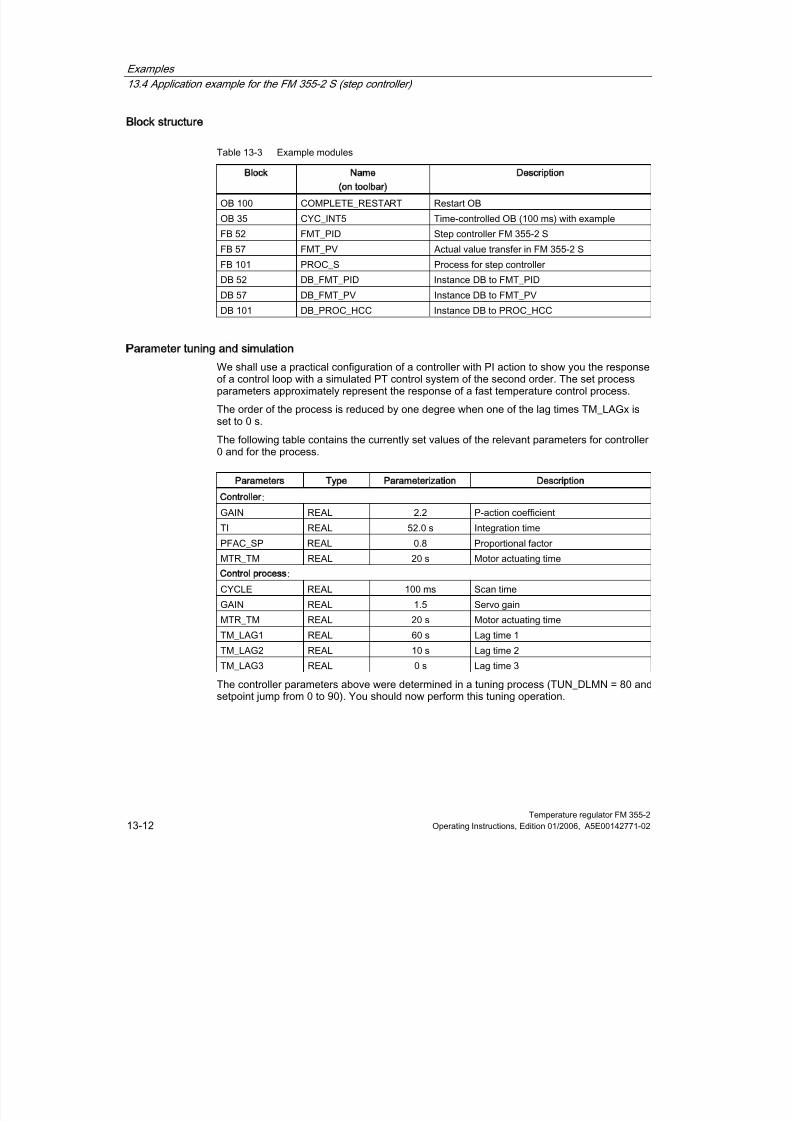
8/11/2019 FM_355-2_e
http://slidepdf.com/reader/full/fm355-2e 178/244
Examples
13.4 Application example for the FM 355-2 S (step controller)
Temperature regulator FM 355-213-12 Operating Instructions, Edition 01/2006, A5E00142771-02
Block structure
Table 13-3 Example modulesBlock Name
(on toolbar)
Description
OB 100 COMPLETE_RESTART Restart OB
OB 35 CYC_INT5 Time-controlled OB (100 ms) with example
FB 52 FMT_PID Step controller FM 355-2 S
FB 57 FMT_PV Actual value transfer in FM 355-2 S
FB 101 PROC_S Process for step controller
DB 52 DB_FMT_PID Instance DB to FMT_PID
DB 57 DB_FMT_PV Instance DB to FMT_PV
DB 101 DB_PROC_HCC Instance DB to PROC_HCC
Parameter tuning and simulation
We shall use a practical configuration of a controller with PI action to show you the responseof a control loop with a simulated PT control system of the second order. The set processparameters approximately represent the response of a fast temperature control process.
The order of the process is reduced by one degree when one of the lag times TM_LAGx isset to 0 s.
The following table contains the currently set values of the relevant parameters for controller0 and for the process.
Parameters Type Parameterization Description
Controller
:
GAIN REAL 2.2 P-action coefficient
TI REAL 52.0 s Integration time
PFAC_SP REAL 0.8 Proportional factor
MTR_TM REAL 20 s Motor actuating time
Control process
:
CYCLE REAL 100 ms Scan time
GAIN REAL 1.5 Servo gain
MTR_TM REAL 20 s Motor actuating time
TM_LAG1 REAL 60 s Lag time 1
TM_LAG2 REAL 10 s Lag time 2
TM_LAG3 REAL 0 s Lag time 3
The controller parameters above were determined in a tuning process (TUN_DLMN = 80 andsetpoint jump from 0 to 90). You should now perform this tuning operation.

8/11/2019 FM_355-2_e
http://slidepdf.com/reader/full/fm355-2e 179/244
Examples
13.4 Application example for the FM 355-2 S (step controller)
Temperature regulator FM 355-2Operating Instructions, Edition 01/2006, A5E00142771-02 13-13
Note
Every time you perform a tuning operation, you will receive slightly different parametervalues for the controller. The reason is that the clock cycle of the watchdog interrupt OBs(e.g. 100 ms) and the cycle time of the FM 355-2 (e.g. 100.5 ms) never match completely.This is why the process model in the CPU does not return a smooth process variable foryour tuning operations on the FM 355-2.
You can subsequently activate setpoint jumps and disturbance variables to test controlresponse (Parameter DISV at DB_PROC_S). Also test the effect of parameter PFAC_SP:For example, when you increase the value in PFAC_SP from 0.8 to 1.0, you will likewiseincrease overshoot.
Please note that you must also set LOAD_PAR = TRUE when you modify parameters viaFMT_PID.
Note
The curve recorder shows the simulated position feedback of the process model. Thisimproves visualization of the sample, but does not exist on a physical step controller withoutposition feedback.

8/11/2019 FM_355-2_e
http://slidepdf.com/reader/full/fm355-2e 180/244
Examples
13.5 Sample application for diagnostics
Temperature regulator FM 355-213-14 Operating Instructions, Edition 01/2006, A5E00142771-02
13.5
135
Sample application for diagnostics
Introduction
In project zEn28_01_FMTemp you can find the sample “Diagnose DS1 FM 355-2 C”,demonstrating the application and evaluation of diagnostics in DS1 of the controller module.
Prerequisites
• Diagnostic interrupts are only triggered in the CPU if you make the following settings inthe ”Basic parameter” tab, under HW Config in the “Properties - FM 355-2 C PID Control”window:
– Generate interrupt: Yes
– Selected interrupt: Diagnosis
Load the sample program
Using the system data, download the configuration to the CPU.
Sample program application
Parameter READ_DS1 of FMT_DS1 will be set in OB 82 when an interrupt occurs. OB 35calls FMT_DS1. It reads the diagnostics data record DS1 of the module.
Block structure
Table 13-4 Example modules
Block Name
(on toolbar)
Description
OB 35 CYC_INT5 Time-controlled OB (100 ms) with example
OB 82 I/O_FLT1 Precise diagnostics of errors
FB 55 FMT_DS1 Reading diagnostic record DS1
DB 55 DB_FMT_DS1 Instance DB to FMT_DS1
See also
Triggering diagnostic interrupts (Page 12-2)

8/11/2019 FM_355-2_e
http://slidepdf.com/reader/full/fm355-2e 181/244
Examples
13.6 Operating the sample with OP 27
Temperature regulator FM 355-2Operating Instructions, Edition 01/2006, A5E00142771-02 13-15
13.6
136
Operating the sample with OP 27
Introduction
The sample project contains the object “FM355-2 BuB”, which is of the type “SIMATIC OP”This represents an operator panel OP27 configuration that is compatible to your sampleprogram. If an OP27 is available to you, you can operate the sample programs by means of“FM355-2 BuB”.
In order to do so, load "FM355-2 BuB" with the configuring software ProTool in the Op 27.Please refer to the OP documentation for the necessary connections and measures.
Home screen
A start screen appears after the OP startup: Here you select the corresponding view for yoursample. The loop monitor opens.
Loop monitor
The loop monitor contains operator control elements for the manual input of setpoints andvalues as well as for manual/auto changeover. In the step controller sample, you can presetthe manipulated value signals for opening and closing the control valve.
Out of this loop monitor you can change to one of the following operator control screens:
• PID parameters
• PID parameters
•
Controller optimization
PID parameters
In this window you can input the PID controller parameters and control zone parameters. Inthe step controller sample you replace the control zone parameters with the motor actuatingtime.
PID parameters
The curve shows the setpoint, as well as the actual value and the manipulated value. In the
step controller sample, the display shows the position feedback value, rather than themanipulated value.
Note
The controller type “Step controller without position feedback” we have used in our sampledoes not have a position feedback element. In the example, it is read from FB PROC_S.

8/11/2019 FM_355-2_e
http://slidepdf.com/reader/full/fm355-2e 182/244
Examples
13.6 Operating the sample with OP 27
Temperature regulator FM 355-213-16 Operating Instructions, Edition 01/2006, A5E00142771-02
Controller optimization
In this window you can start controller tuning.
1.
Monitor the curve recorder until the quasi-static state is reached.2. Press F6 to set the controller ready for tuning.
3. Check the manipulated value difference.
4. Check the manipulated value difference.
5. Monitor the curve.
6. Check the result by means of parameter PHASE and STATUS_H.
See also
Overview (Page 7-1)

8/11/2019 FM_355-2_e
http://slidepdf.com/reader/full/fm355-2e 183/244
Examples
13.7 Example of a cascade control circuit
Temperature regulator FM 355-2Operating Instructions, Edition 01/2006, A5E00142771-02 13-17
13.7
137
Example of a cascade control circuit
Dual-loop cascade circuit
The figure below shows the dual-loop cascade control of a module:
Figure 13-7 Dual-loop cascade circuit
To create this controller circuit with an FM 355-2 S, configure a pulse controller withreference variable algorithm and select the manipulated value of the reference variablecontroller at the setpoint input of the follow-up controller.
You can also generate a cascade control with an FM 355-2 C. In this case, the referencevariable controllers are closed-loop controllers and the follow-up controllers are configuredas “Set-value or cascade controller”. The circuit is identical.
In the follow-up controller, the manipulated value of the reference variable controller isscaled to 0 to 100% of the value range of actual value A, and is then further processed assetpoint value.
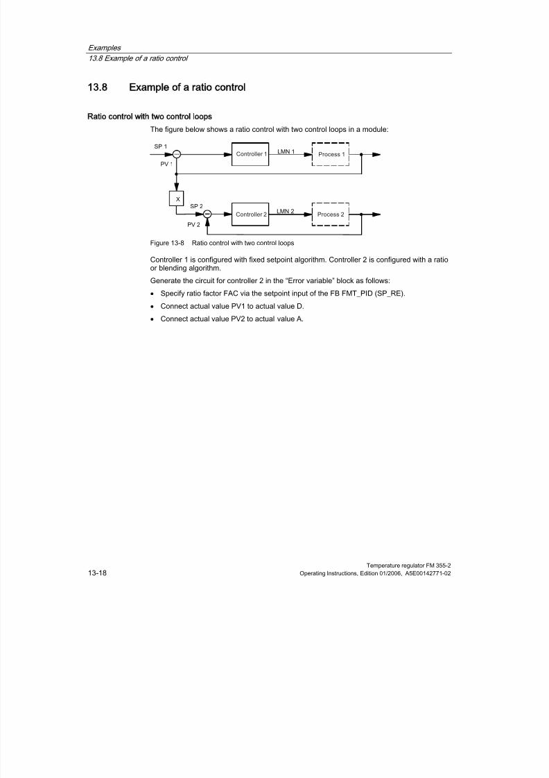
8/11/2019 FM_355-2_e
http://slidepdf.com/reader/full/fm355-2e 184/244
Examples
13.8 Example of a ratio control
Temperature regulator FM 355-213-18 Operating Instructions, Edition 01/2006, A5E00142771-02
13.8
138
Example of a ratio control
Ratio control with two control loops
The figure below shows a ratio control with two control loops in a module:
Figure 13-8 Ratio control with two control loops
Controller 1 is configured with fixed setpoint algorithm. Controller 2 is configured with a ratioor blending algorithm.
Generate the circuit for controller 2 in the “Error variable” block as follows:
• Specify ratio factor FAC via the setpoint input of the FB FMT_PID (SP_RE).
• Connect actual value PV1 to actual value D.
• Connect actual value PV2 to actual value A.
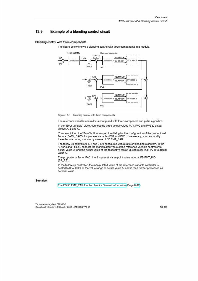
8/11/2019 FM_355-2_e
http://slidepdf.com/reader/full/fm355-2e 185/244
Examples
13.9 Example of a blending control circuit
Temperature regulator FM 355-2Operating Instructions, Edition 01/2006, A5E00142771-02 13-19
13.9
139
Example of a blending control circuit
Blending control with three components
The figure below shows a blending control with three components in a module.
Figure 13-9 Blending control with three components
The reference variable controller is configured with three-component and pulse algorithm.
In the “Error variable” block, connect the three actual values PV1, PV2 and PV3 to actualvalues A, B and C.
You can click on the “Sum” button to open the dialog for the configuration of the proportionalfactors (FAC4, FAC5) for process variables PV2 and PV3. If necessary, you can modifythese factors during runtime by means of FB FMT_PAR.
The follow-up controllers 1, 2 and 3 are configured with a ratio or blending algorithm. In the“Error signal” block, connect the manipulated value of the reference variable controller toactual value D, and the actual value of the respective follow-up controller (e.g. PV1) to actualvalue A.
The proportional factor FAC 1 to 3 is preset via setpoint value input at FB FMT_PID(SP_RE).
In the follow-up controller, the manipulated value of the reference variable controller isscaled to 0 to 100% of the value range of actual value A, and is then further processed assetpoint value.
See also
The FB 53 FMT_PAR function block - General information (Page 8-12)

8/11/2019 FM_355-2_e
http://slidepdf.com/reader/full/fm355-2e 186/244
Examples
13.9 Example of a blending control circuit
Temperature regulator FM 355-213-20 Operating Instructions, Edition 01/2006, A5E00142771-02

8/11/2019 FM_355-2_e
http://slidepdf.com/reader/full/fm355-2e 187/244
Temperature regulator FM 355-2Operating Instructions, Edition 01/2006, A5E00142771-02 A-1
AData sheets
A
A.1
A1
Technical Specifications S7-300
General technical specifications
General technical specifications are
• Electromagnetic compatibility
• Shipping and storage conditions
• Mechanical and climatic environmental conditions
• Specifications for insulation tests, protection class and degree of protection
These general technical specifications are explained in Manual /1/. They contain standardsand test values that the S7-300 fulfils and the criteria used to test the S7-300.
Approbations
The S7-300 has the following approvals:
UL Recognition MarkUnderwriters Laboratories (UL) in accordance with Standard UL 508
CSA-Certification-MarkCanadian Standard Association (CSA) to Standard C22.2 No. 142
FM approval complying with Factory Mutual Approval Standard Class Number 3611, Class I,Division 2, Group A, B, C, D
Warning
Personal injury and material damage may be incurred.
In potentially explosive environments, there is a risk of injury or damage if you disconnectany connectors while the S7-300 is in operation.
Always isolate the S7-300 operated in such areas before you disconnect and connectors.

8/11/2019 FM_355-2_e
http://slidepdf.com/reader/full/fm355-2e 188/244
Data sheets
A.1 Technical Specifications S7-300
Temperature regulator FM 355-2A-2 Operating Instructions, Edition 01/2006, A5E00142771-02
Warning
DO NOT DISCONNECT WHILE CIRCUIT IS LIVE UNLESS LOCATION IS KNOWN TO BENONHAZARDOUS
CE Marking
Our products fulfill the requirements of the EU Directive 89/336/EEC ”Electromagneticcompatibility”.
The EU conformity certificates are available for the relevant authorities and are kept at thefollowing address in accordance with the above-mentioned EU Directive. Article 10:
Siemens AktiengesellschaftBereich Automatisierungs- und AntriebstechnikA&D AS RD ST PLCPostfach 1963D-92209 Amberg
Area of Application
SIMATIC products are designed for use in industrial environments.
SIMATIC products may be also used in combination with an individual license in residentialareas (residential, commercial and industrial areas, small enterprises).
Area of application Requirements in respect of
Emitted interference Interference immunity
Industry EN 50081-2 : 1993 EN 50082-2 : 1995
Observe the Installation Guidelines
SIMATIC products fulfill the requirement if you observe the installation guidelines describedin the manuals during installation and operation.
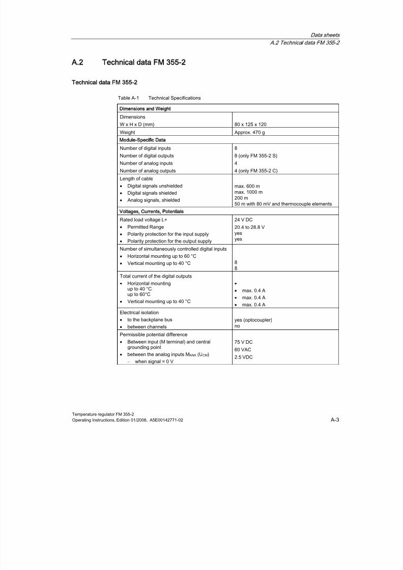
8/11/2019 FM_355-2_e
http://slidepdf.com/reader/full/fm355-2e 189/244
Data sheets
A.2 Technical data FM 355-2
Temperature regulator FM 355-2Operating Instructions, Edition 01/2006, A5E00142771-02 A-3
A.2
A2Technical data FM 355-2
Technical data FM 355-2
Table A-1 Technical Specifications
Dimensions and Weight
Dimensions
W x H x D (mm) 80 x 125 x 120
Weight Approx. 470 g
Module-Specific Data
Number of digital inputs
Number of digital outputs
Number of analog inputs
Number of analog outputs
8
8 (only FM 355-2 S)
4
4 (only FM 355-2 C)
Length of cable
•
Digital signals unshielded
•
Digital signals shielded
•
Analog signals, shielded
max. 600 mmax. 1000 m200 m50 m with 80 mV and thermocouple elements
Voltages, Currents, Potentials
Rated load voltage L+
•
Permitted Range
•
Polarity protection for the input supply
•
Polarity protection for the output supply
24 V DC
20.4 to 28.8 Vyes
yesNumber of simultaneously controlled digital inputs
•
Horizontal mounting up to 60 °C
•
Vertical mounting up to 40 °C 88
Total current of the digital outputs
•
Horizontal mountingup to 40 °Cup to 60°C
•
Vertical mounting up to 40 °C
•
•
max. 0.4 A
•
max. 0.4 A
•
max. 0.4 A
Electrical isolation
•
to the backplane bus•
between channelsyes (optocoupler)no
Permissible potential difference
•
Between input (M terminal) and centralgrounding point
•
between the analog inputs MANA (UCM)
– when signal = 0 V
75 V DC
60 VAC
2.5 VDC
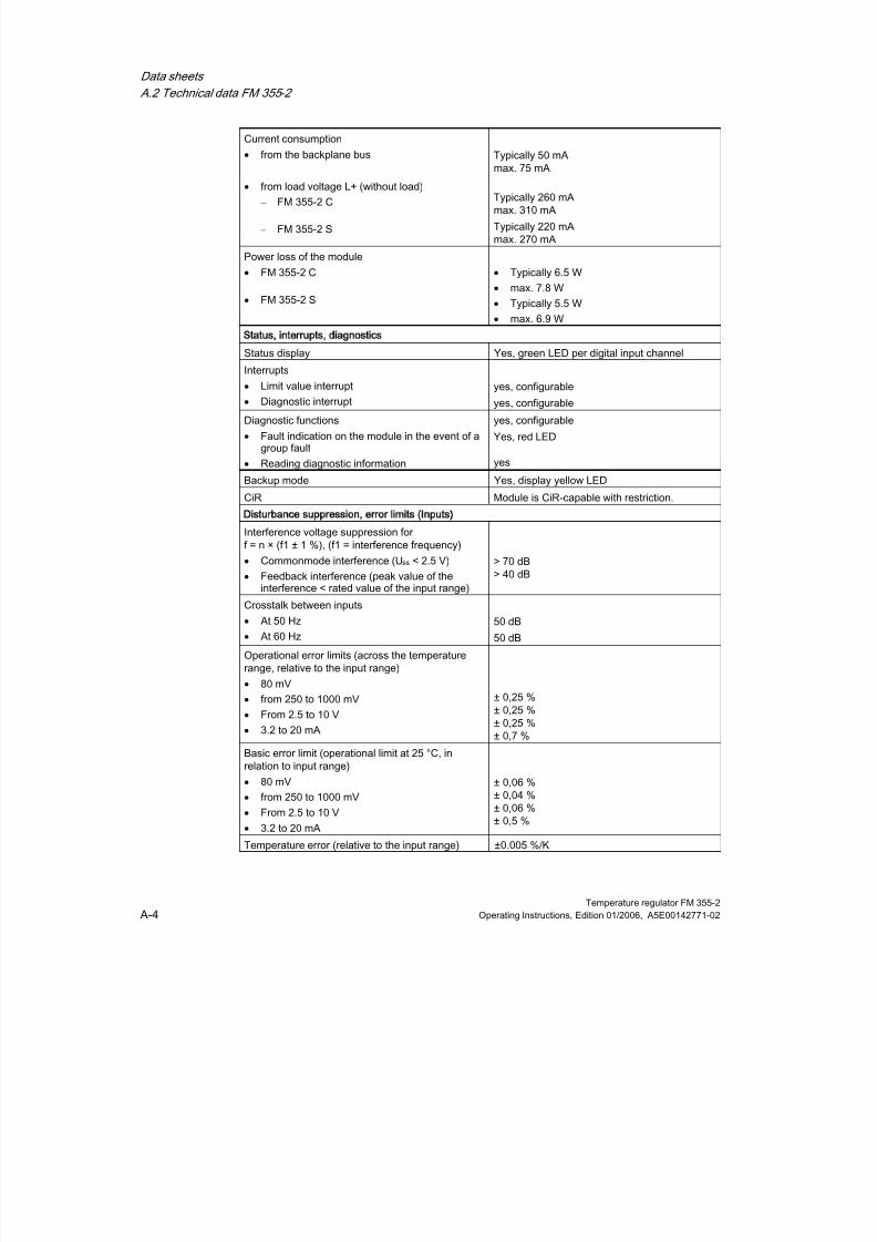
8/11/2019 FM_355-2_e
http://slidepdf.com/reader/full/fm355-2e 190/244
Data sheets
A.2 Technical data FM 355-2
Temperature regulator FM 355-2A-4 Operating Instructions, Edition 01/2006, A5E00142771-02
Current consumption
•
from the backplane bus
• from load voltage L+ (without load)
– FM 355-2 C
– FM 355-2 S
Typically 50 mAmax. 75 mA
Typically 260 mAmax. 310 mA
Typically 220 mAmax. 270 mA
Power loss of the module
• FM 355-2 C
•
FM 355-2 S
• Typically 6.5 W
•
max. 7.8 W
•
Typically 5.5 W
•
max. 6.9 W
Status, interrupts, diagnostics
Status display Yes, green LED per digital input channel
Interrupts
•
Limit value interrupt
•
Diagnostic interrupt
yes, configurable
yes, configurable
Diagnostic functions
• Fault indication on the module in the event of agroup fault
•
Reading diagnostic information
yes, configurable
Yes, red LED
yes
Backup mode Yes, display yellow LED
CiR Module is CiR-capable with restriction.
Disturbance suppression, error limits (Inputs)
Interference voltage suppression forf = n × (f1 ± 1 %), (f1 = interference frequency)
•
Commonmode interference (Uss < 2.5 V)
•
Feedback interference (peak value of theinterference < rated value of the input range)
> 70 dB> 40 dB
Crosstalk between inputs
•
At 50 Hz
•
At 60 Hz
50 dB
50 dB
Operational error limits (across the temperaturerange, relative to the input range)
• 80 mV
•
from 250 to 1000 mV•
From 2.5 to 10 V
•
3.2 to 20 mA
± 0,25 %± 0,25 %± 0,25 %± 0,7 %
Basic error limit (operational limit at 25 °C, inrelation to input range)
•
80 mV
•
from 250 to 1000 mV
•
From 2.5 to 10 V
• 3.2 to 20 mA
± 0,06 %± 0,04 %± 0,06 %± 0,5 %
Temperature error (relative to the input range) ±0.005 %/K
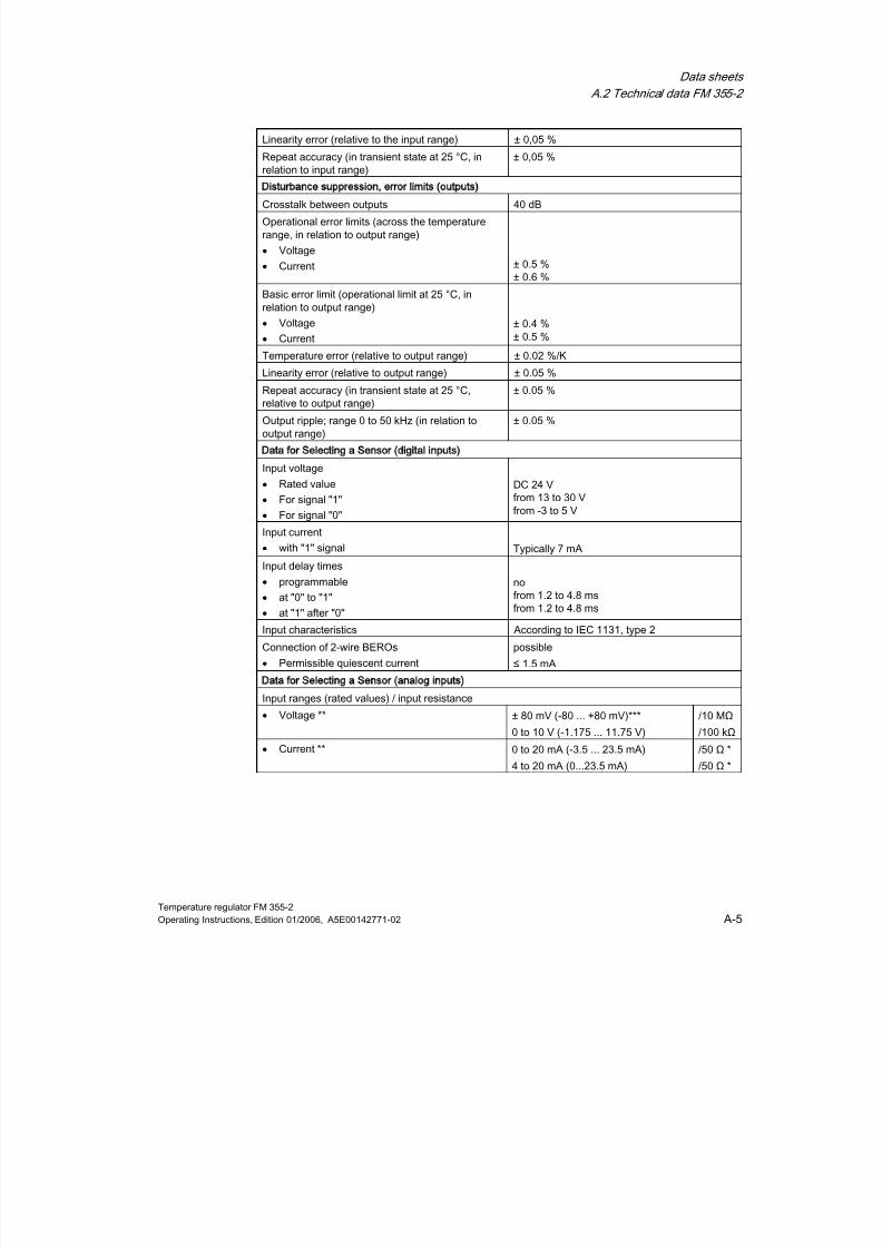
8/11/2019 FM_355-2_e
http://slidepdf.com/reader/full/fm355-2e 191/244
Data sheets
A.2 Technical data FM 355-2
Temperature regulator FM 355-2Operating Instructions, Edition 01/2006, A5E00142771-02 A-5
Linearity error (relative to the input range) ± 0,05 %
Repeat accuracy (in transient state at 25 °C, in
relation to input range)
± 0,05 %
Disturbance suppression, error limits (outputs)
Crosstalk between outputs 40 dB
Operational error limits (across the temperaturerange, in relation to output range)
•
Voltage
• Current ± 0.5 %± 0.6 %
Basic error limit (operational limit at 25 °C, inrelation to output range)
•
Voltage
•
Current
± 0.4 %± 0.5 %
Temperature error (relative to output range) ± 0.02 %/K
Linearity error (relative to output range) ± 0.05 %
Repeat accuracy (in transient state at 25 °C,relative to output range)
± 0.05 %
Output ripple; range 0 to 50 kHz (in relation tooutput range)
± 0.05 %
Data for Selecting a Sensor (digital inputs)
Input voltage
•
Rated value
•
For signal "1"
•
For signal "0"
DC 24 Vfrom 13 to 30 Vfrom -3 to 5 V
Input current
•
with "1" signal Typically 7 mA
Input delay times
•
programmable
•
at "0" to "1"
•
at "1" after "0"
nofrom 1.2 to 4.8 msfrom 1.2 to 4.8 ms
Input characteristics According to IEC 1131, type 2
Connection of 2-wire BEROs
•
Permissible quiescent current
possible
≤ 1.5 mA
Data for Selecting a Sensor (analog inputs)
Input ranges (rated values) / input resistance•
Voltage ** ± 80 mV (-80 ... +80 mV)***
0 to 10 V (-1.175 ... 11.75 V)
/10 MΩ
/100 kΩ
•
Current ** 0 to 20 mA (-3.5 ... 23.5 mA)
4 to 20 mA (0...23.5 mA)
/50 Ω *
/50 Ω *
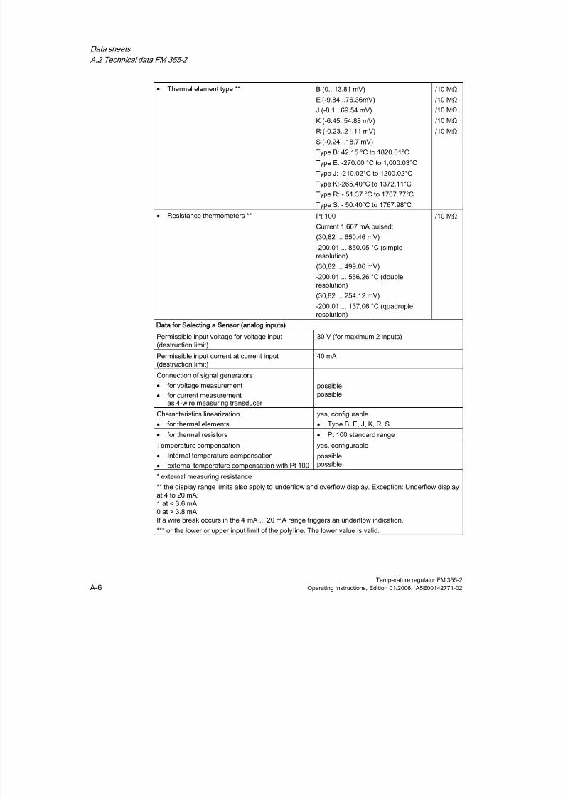
8/11/2019 FM_355-2_e
http://slidepdf.com/reader/full/fm355-2e 192/244
Data sheets
A.2 Technical data FM 355-2
Temperature regulator FM 355-2A-6 Operating Instructions, Edition 01/2006, A5E00142771-02
•
Thermal element type ** B (0...13.81 mV)
E (-9.84...76.36mV)
J (-8.1...69.54 mV)K (-6.45..54.88 mV)
R (-0.23..21.11 mV)
S (-0.24...18.7 mV)
Type B: 42.15 °C to 1820.01°C
Type E: -270.00 °C to 1,000.03°C
Type J: -210.02°C to 1200.02°C
Type K:-265.40°C to 1372.11°C
Type R: - 51.37 °C to 1767.77°C
Type S: - 50.40°C to 1767.98°C
/10 MΩ
/10 MΩ
/10 MΩ/10 MΩ
/10 MΩ
•
Resistance thermometers ** Pt 100
Current 1.667 mA pulsed:
(30,82 ... 650.46 mV)
-200.01 ... 850.05 °C (simpleresolution)
(30,82 ... 499.06 mV)
-200.01 ... 556.26 °C (doubleresolution)
(30,82 ... 254.12 mV)
-200.01 ... 137.06 °C (quadrupleresolution)
/10 MΩ
Data for Selecting a Sensor (analog inputs)
Permissible input voltage for voltage input(destruction limit)
30 V (for maximum 2 inputs)
Permissible input current at current input(destruction limit)
40 mA
Connection of signal generators
•
for voltage measurement
•
for current measurementas 4-wire measuring transducer
possiblepossible
Characteristics linearization
•
for thermal elements
yes, configurable
•
Type B, E, J, K, R, S
•
for thermal resistors •
Pt 100 standard range
Temperature compensation•
Internal temperature compensation
•
external temperature compensation with Pt 100
yes, configurablepossiblepossible
* external measuring resistance
** the display range limits also apply to underflow and overflow display. Exception: Underflow displayat 4 to 20 mA:1 at < 3.6 mA0 at > 3.8 mAIf a wire break occurs in the 4 mA ... 20 mA range triggers an underflow indication.
*** or the lower or upper input limit of the polyline. The lower value is valid.
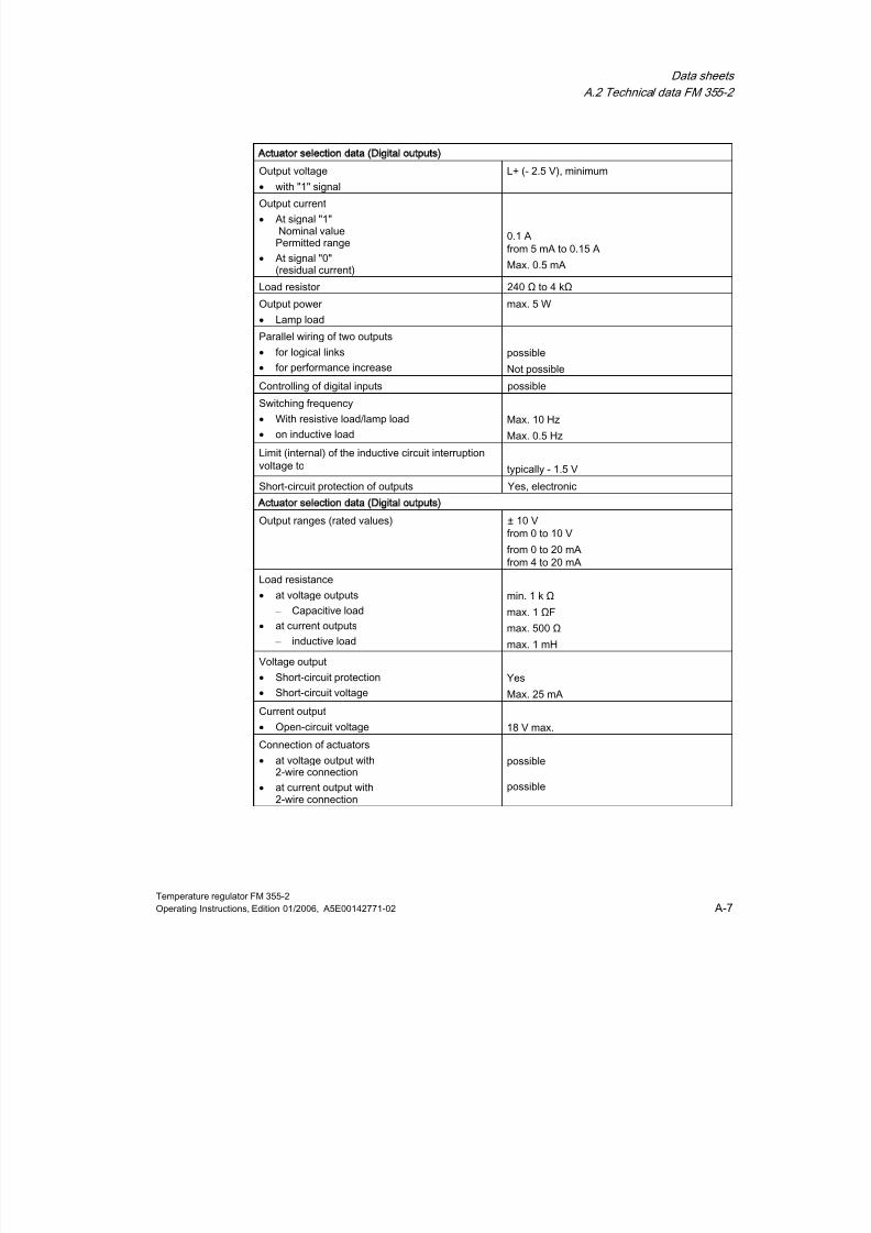
8/11/2019 FM_355-2_e
http://slidepdf.com/reader/full/fm355-2e 193/244
Data sheets
A.2 Technical data FM 355-2
Temperature regulator FM 355-2Operating Instructions, Edition 01/2006, A5E00142771-02 A-7
Actuator selection data (Digital outputs)
Output voltage•
with "1" signalL+ (- 2.5 V), minimum
Output current
•
At signal "1"Nominal valuePermitted range
• At signal "0"(residual current)
0.1 Afrom 5 mA to 0.15 A
Max. 0.5 mA
Load resistor 240 Ω to 4 kΩ
Output power
•
Lamp load
max. 5 W
Parallel wiring of two outputs
•
for logical links
• for performance increase
possible
Not possible
Controlling of digital inputs possible
Switching frequency
• With resistive load/lamp load
•
on inductive load
Max. 10 Hz
Max. 0.5 Hz
Limit (internal) of the inductive circuit interruptionvoltage to typically - 1.5 V
Short-circuit protection of outputs Yes, electronic
Actuator selection data (Digital outputs)
Output ranges (rated values) ± 10 Vfrom 0 to 10 V
from 0 to 20 mAfrom 4 to 20 mA
Load resistance
• at voltage outputs
– Capacitive load
•
at current outputs
– inductive load
min. 1 k Ω
max. 1 ΩF
max. 500 Ω
max. 1 mH
Voltage output
• Short-circuit protection
•
Short-circuit voltage
Yes
Max. 25 mACurrent output
•
Open-circuit voltage 18 V max.
Connection of actuators
• at voltage output with2-wire connection
•
at current output with2-wire connection
possible
possible

8/11/2019 FM_355-2_e
http://slidepdf.com/reader/full/fm355-2e 194/244
Data sheets
A.2 Technical data FM 355-2
Temperature regulator FM 355-2A-8 Operating Instructions, Edition 01/2006, A5E00142771-02
Analog value generation
Measuring principle
Resolution (including. overshoot range)Conversion time (per analog input)
integrating
14 bits100 ms
Settling time
•
with resistive load
•
with capacitive load
•
for inductive load
0.1 ms3.3 ms0.5 ms
Input of substitution values yes, configurable
Integration / conversion time / resolution (perchannel)
•
programmable
•
Integration time in ms
•
Basic conversion time including the processingtime in ms
•
additional conversion time for resistancemeasurement in msoradditional conversion time for reference junctioninput in ms
100102
1
100
•
Resolution in bits (including overshoot range)measuring range
14
•
Interference voltage suppression at interferencefrequency f1 in Hz
50, 60
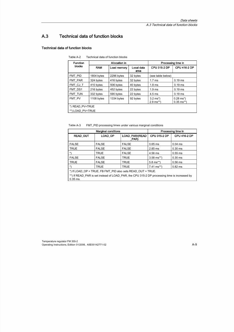
8/11/2019 FM_355-2_e
http://slidepdf.com/reader/full/fm355-2e 195/244
Data sheets
A.3 Technical data of function blocks
Temperature regulator FM 355-2Operating Instructions, Edition 01/2006, A5E00142771-02 A-9
A.3
A3Technical data of function blocks
Technical data of function blocks
Table A-2 Technical data of function blocks
Allocation in Processing time inunction
blocks
RAM Load memory Local data
area
CPU 315-2 DP CPU 416-2 DP
FMT_PID 1804 bytes 2296 bytes 32 bytes (see table below)
FMT_PAR 324 bytes 416 bytes 32 bytes 1.7 ms 0.19 ms
FMT_CJ_T 410 bytes 506 bytes 40 bytes 1.8 ms 0.19 ms
FMT_DS1 216 bytes 452 bytes 22 bytes 1.9 ms 0.19 ms
FMT_TUN 332 bytes 590 bytes 22 bytes 4.5 ms 0.19 ms
FMT_PV 1108 bytes 1334 bytes 92 bytes 3.2 ms*)2.9 ms**)
0.28 ms*)0.35 ms**)
*) READ_PV=TRUE
**) LOAD_PV=TRUE
Table A-3 FMT_PID processing times under various marginal conditions
Marginal conditions Processing time in
READ_OUT LOAD_OP LOAD_PAR/(READ
_PAR)
CPU 315-2 DP CPU 416-2 DP
FALSE FALSE FALSE 0.65 ms 0.04 ms
TRUE FALSE FALSE 2.85 ms 0.30 ms
*) TRUE FALSE 4.56 ms 0.55 ms
FALSE FALSE TRUE 3.58 ms**) 0.30 ms
TRUE FALSE TRUE 5.8 ms**) 0.56 ms
*) TRUE TRUE 7.41 ms**) 0.82 ms
*) If LOAD_OP = TRUE, FB FMT_PID also sets READ_OUT = TRUE.
**) If READ_PAR is set instead of LOAD_PAR, the CPU 315-2 DP processing time is increased by0.35 ms.

8/11/2019 FM_355-2_e
http://slidepdf.com/reader/full/fm355-2e 196/244
Data sheets
A.3 Technical data of function blocks
Temperature regulator FM 355-2A-10 Operating Instructions, Edition 01/2006, A5E00142771-02
Table A-4 Technical data of the instance DBs
Allocation innstance DBs of the function
blocks ...
RAM Load memory
FMT_PID 210 bytes 610 bytes
FMT_PAR 52 bytes 128 bytes
FMT_CJ_T 50 bytes 130 bytes
FMT_DS1 282 bytes 56 bytes
FMT_TUN 254 bytes 502 bytes
FMT_PV 100 bytes 302 bytes
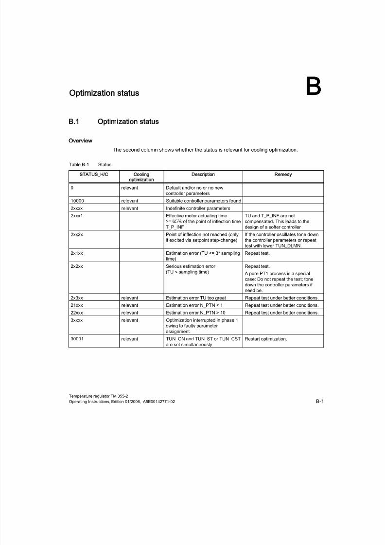
8/11/2019 FM_355-2_e
http://slidepdf.com/reader/full/fm355-2e 197/244
Temperature regulator FM 355-2Operating Instructions, Edition 01/2006, A5E00142771-02 B-1
BOptimization status
B
B.1
B1
Optimization status
Overview
The second column shows whether the status is relevant for cooling optimization.
Table B-1 Status
STATUS_H/C Cooling
optimization
Description Remedy
0 relevant Default and/or no or no newcontroller parameters
10000 relevant Suitable controller parameters found
2xxxx relevant Indefinite controller parameters
2xxx1 Effective motor actuating time>= 65% of the point of inflection time
T_P_INF
TU and T_P_INF are notcompensated. This leads to the
design of a softer controller2xx2x Point of inflection not reached (only
if excited via setpoint step-change)If the controller oscillates tone downthe controller parameters or repeattest with lower TUN_DLMN.
2x1xx Estimation error (TU <= 3* samplingtime)
Repeat test.
2x2xx Serious estimation error(TU < sampling time)
Repeat test.
A pure PT1 process is a specialcase: Do not repeat the test; tonedown the controller parameters ifneed be.
2x3xx relevant Estimation error TU too great Repeat test under better conditions.
21xxx relevant Estimation error N_PTN < 1 Repeat test under better conditions.22xxx relevant Estimation error N_PTN > 10 Repeat test under better conditions.
3xxxx relevant Optimization interrupted in phase 1owing to faulty parameterassignment
30001 relevant TUN_ON and TUN_ST or TUN_CSTare set simultaneously
Restart optimization.
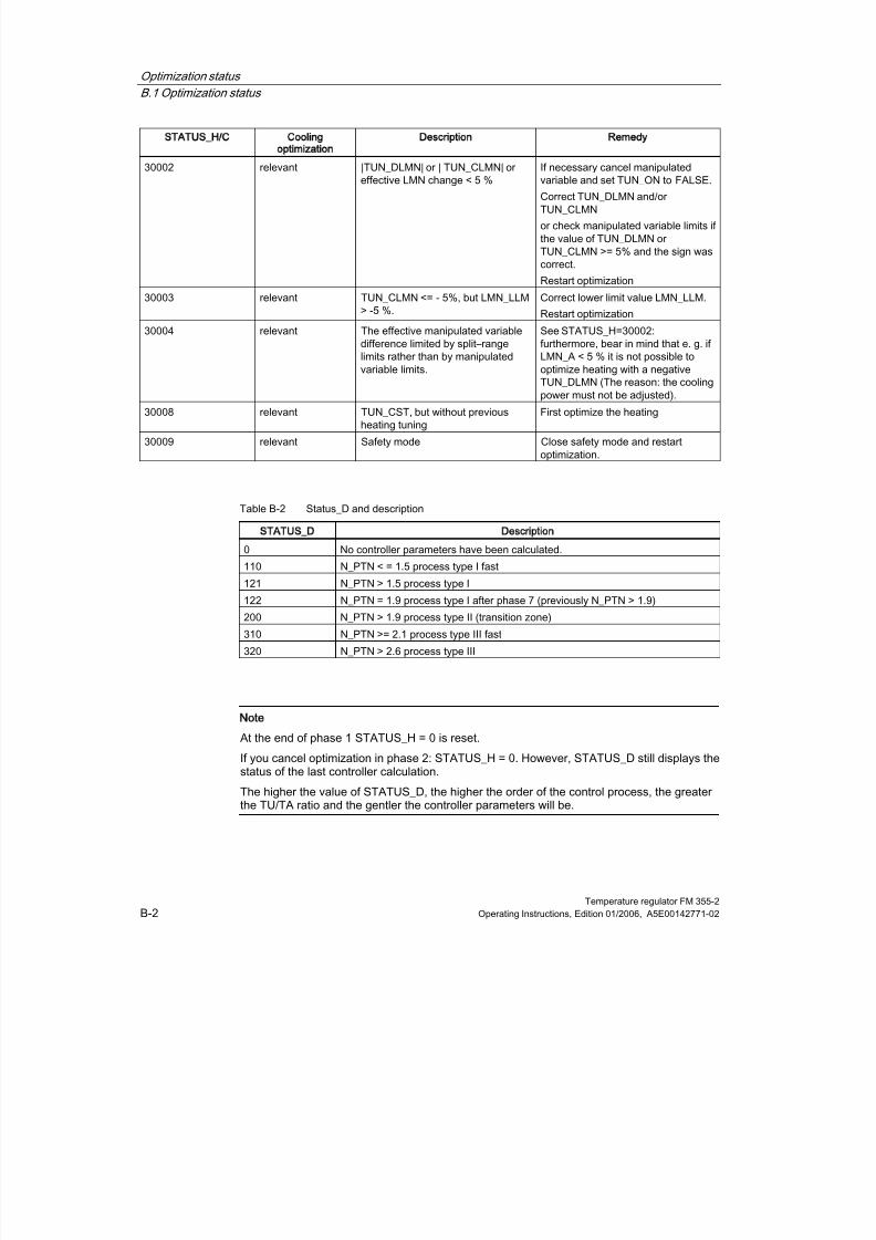
8/11/2019 FM_355-2_e
http://slidepdf.com/reader/full/fm355-2e 198/244
Optimization status
B.1 Optimization status
Temperature regulator FM 355-2B-2 Operating Instructions, Edition 01/2006, A5E00142771-02
STATUS_H/C Cooling
optimization
Description Remedy
30002 relevant |TUN_DLMN| or | TUN_CLMN| oreffective LMN change < 5 %
If necessary cancel manipulatedvariable and set TUN_ON to FALSE.
Correct TUN_DLMN and/orTUN_CLMN
or check manipulated variable limits ifthe value of TUN_DLMN orTUN_CLMN >= 5% and the sign wascorrect.
Restart optimization
30003 relevant TUN_CLMN <= - 5%, but LMN_LLM> -5 %.
Correct lower limit value LMN_LLM.
Restart optimization
30004 relevant The effective manipulated variable
difference limited by split–rangelimits rather than by manipulatedvariable limits.
See STATUS_H=30002:
furthermore, bear in mind that e. g. ifLMN_A < 5 % it is not possible tooptimize heating with a negativeTUN_DLMN (The reason: the coolingpower must not be adjusted).
30008 relevant TUN_CST, but without previousheating tuning
First optimize the heating
30009 relevant Safety mode Close safety mode and restartoptimization.
Table B-2 Status_D and description
STATUS_D Description
0 No controller parameters have been calculated.
110 N_PTN < = 1.5 process type I fast
121 N_PTN > 1.5 process type I
122 N_PTN = 1.9 process type I after phase 7 (previously N_PTN > 1.9)
200 N_PTN > 1.9 process type II (transition zone)
310 N_PTN >= 2.1 process type III fast
320 N_PTN > 2.6 process type III
Note
At the end of phase 1 STATUS_H = 0 is reset.
If you cancel optimization in phase 2: STATUS_H = 0. However, STATUS_D still displays thestatus of the last controller calculation.
The higher the value of STATUS_D, the higher the order of the control process, the greaterthe TU/TA ratio and the gentler the controller parameters will be.
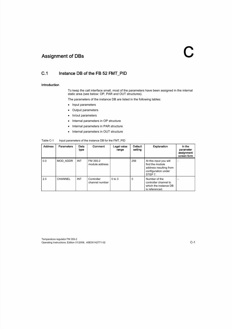
8/11/2019 FM_355-2_e
http://slidepdf.com/reader/full/fm355-2e 199/244
Temperature regulator FM 355-2Operating Instructions, Edition 01/2006, A5E00142771-02 C-1
CAssignment of DBs
C
C.1
C1
Instance DB of the FB 52 FMT_PID
Introduction
To keep the call interface small, most of the parameters have been assigned in the internalstatic area (see below: OP, PAR and OUT structures).
The parameters of the instance DB are listed in the following tables:
• Input parameters
• Output parameters
• In/out parameters
• Internal parameters in OP structure
• Internal parameters in PAR structure
• Internal parameters in OUT structure
Table C-1 Input parameters of the instance DB for the FMT_PID
Address Parameters Data
type
Comment Legal value
range
Default
setting
Explanation In the
parameter
assignment
screen form
0.0 MOD_ADDR INT FM 355-2module address
256 At this input you willfind the moduleaddress resulting fromconfiguration underSTEP 7.
-
2.0 CHANNEL INT Controllerchannel number
0 to 3 0 Number of thecontroller channel towhich the instance DBis referenced.
-

8/11/2019 FM_355-2_e
http://slidepdf.com/reader/full/fm355-2e 200/244
Assignment of DBs
C.1 Instance DB of the FB 52 FMT_PID
Temperature regulator FM 355-2C-2 Operating Instructions, Edition 01/2006, A5E00142771-02
Table C-2 Output parameters of the instance DB for the FMT_PID
Address Parameters Data
type
Comment Legal value
range
Default
setting
Explanation In the
parameter
assignment
screen form
4.0 QMOD_F BOOL Module faults FALSE The function blockchecks correct readingand writing of a datarecord. If errors areidentified, the QMOD_Foutput is set. Thecause of errors can be:an incorrect moduleaddress on the
MOD_ADDRparameter, an incorrectchannel number on theCHANNEL parameteror a defective module.
-
6.0 RET_VALU WORD Return value ofSFB 52/53
W#16#0 Output STATUS (bytes2 and 3) of SFB52/53;corresponding to theerror code RET_VAL ofSFC58/59
-
Table C-3 In/Out parameters of the instance DB for the FMT_PID
Address Parameters Data
type
Comment Legal value
range
Default
setting
Explanation In the
parameter
assignment
screen form
8.0 COM_RST BOOL Cold restart FALSE When COM_RST =TRUE the FBFMT_PID performs aninitialization run andresets COM_RST Thisinitialization isimperative every timethe CPU starts up.
-
8.1 LOAD_OP BOOL Downloadoperatorparameters toFM 355-2
FALSE If the LOAD_OP I/Oparameter has beenset, the operatingparameters aredownloaded to themodule, the outputparameters are readand the I/Oparameters are reset.
-
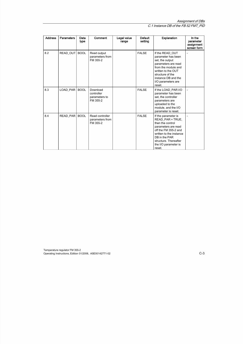
8/11/2019 FM_355-2_e
http://slidepdf.com/reader/full/fm355-2e 201/244
Assignment of DBs
C.1 Instance DB of the FB 52 FMT_PID
Temperature regulator FM 355-2Operating Instructions, Edition 01/2006, A5E00142771-02 C-3
Address Parameters Data
type
Comment Legal value
range
Default
setting
Explanation In the
parameter
assignment
screen form
8.2 READ_OUT BOOL Read outputparameters fromFM 355-2
FALSE If the READ_OUTparameter has beenset, the outputparameters are readfrom the module andwritten to the OUTstructure of theinstance DB and theI/O parameters arereset.
-
8.3 LOAD_PAR BOOL Downloadcontroller
parameters toFM 355-2
FALSE If the LOAD_PAR I/Oparameter has been
set, the controllerparameters areuploaded to themodule, and the I/Oparameter is reset.
-
8.4 READ_PAR BOOL Read controllerparameters fromFM 355-2
FALSE If the parameter isREAD_PAR = TRUE,then the controlparameters are readoff the FM 355-2 andwritten to the instanceDB in the PARstructure. Thereafter
the I/O parameter isreset.
-

8/11/2019 FM_355-2_e
http://slidepdf.com/reader/full/fm355-2e 202/244
Assignment of DBs
C.1 Instance DB of the FB 52 FMT_PID
Temperature regulator FM 355-2C-4 Operating Instructions, Edition 01/2006, A5E00142771-02
Table C-4 Internal parameters of the instance DB for FMT_PID (operating parameters in OP structure)
Address Parameters Data
type
Comment Legal value
range
Default
setting
Explanation In the
parameter
assignment
screen form
10.0 vers_no WORD Version, always16#3230, do notchange
W#16#3230 W#16#3230 The parametervers_no may notbe changed by theuser. It identifiesthe start of theoperatorparameters thatare transferred tothe module, if
LOAD_OP = TRUEis set.
-
12.0 SP_RE REAL external setpoint technicalvalue range(physic.variable)
0.0 An externalsetpoint isinterconnected withthe controller atinput SP_RE. *)
-
16.0 LMN_RE REAL externalmanipulatedvariable
-100.0...100.0(%)
0.0 An externalmanipulatedvariable isinterconnected withthe controller atinput LMN_RE. *)
-
20.0 SAFE_ON BOOL Setting safety mode FALSE When SAFE_ON isset, a safety valueis adopted as themanipulatedvariable.
-
20.1 LMNTRKON BOOL Correct (LMN via AI) FALSE If LMNTRKON isset, themanipulatedvariable iscorrected to ananalog input (AI)(does not apply tostep-action
controllers withoutanalog positionfeedback)
-
20.2 LMN_REON BOOL enable externalmanipulatedvariable
FALSE If LMN_REON isset, the externalmanipulatedvariable LMN_REis applied (manualmode).
-

8/11/2019 FM_355-2_e
http://slidepdf.com/reader/full/fm355-2e 203/244
Assignment of DBs
C.1 Instance DB of the FB 52 FMT_PID
Temperature regulator FM 355-2Operating Instructions, Edition 01/2006, A5E00142771-02 C-5
Address Parameters Data
type
Comment Legal value
range
Default
setting
Explanation In the
parameter
assignment
screen form
20.3 LMNRHSRE BOOL upper end signal ofthe positionfeedback
FALSE The "control valveat high stop" signalcan beinterconnected witha digital input of theFM 355-2 or at theLMNRHSRE input.LMNRHSRE =TRUE means: Thecontrol valve is atthe high stop.(Applies to step-
action controllersonly).
-
20.4 LMNRLSRE BOOL lower end signal ofthe positionfeedback
FALSE The "manipulatedvalve on low stop"signal can beinterconnected witha digital input of theFM 355-2 or at theLMNRLSRE input.LMNRHSRE =TRUE means: Thecontrol valve is atthe low stop.
(Applies to step-action controllersonly).
-
20.5 LMNS_ON BOOL Enable operatorcontrol ofmanipulatedvariables
FALSE Enable operatorcontrol ofmanipulatedvariables (appliesonly to step-actioncontroller, manualmode)
-
20.6 LMN_UP BOOL Manipulatedvariable High signaloperation
FALSE Manipulatedvariable Highsignal operation
(applies to step-action controllersonly).
-
20.7 LMN_DN BOOL Manipulatedvariable Low signaloperation
FALSE Manipulatedvariable Low signaloperation (appliesto step-actioncontrollers only).
-

8/11/2019 FM_355-2_e
http://slidepdf.com/reader/full/fm355-2e 204/244
Assignment of DBs
C.1 Instance DB of the FB 52 FMT_PID
Temperature regulator FM 355-2C-6 Operating Instructions, Edition 01/2006, A5E00142771-02
Address Parameters Data
type
Comment Legal value
range
Default
setting
Explanation In the
parameter
assignment
screen form
22.0 SAVE_PAR BOOL Save controllerparameters
FALSE Saves currentcontrollerparameters:(SAV_PFAC=PFAC_SP, SAV_GAIN=GAIN, SAV_TI=TI, SAV_TD = TD,SAV_D_F =D_F,SAV_CONZ =CON_ZONE,SAV_RATI=RATIOFAC,
SAV_CZON=CONZ_ON,SAV_PSEL=P_SEL) **).
-
22.1 UNDO_PAR BOOL Undoing controllerparameter changes
FALSE The savedcontrollerparameters areretrieved again,also in automaticmode.(PFAC_SP=SAV_PFAC, GAIN =SAV_GAIN, TI
=SAV_TI, TD =SAV_TD, D_F =SAV_D_F,CON_ZONE =SAV_CONZ,RATIOFAC =SAV_RATI,CONZ_ON=SAV_CZON,P_SEL=SAV_PSEL) **).
-
22.2 LOAD_PID BOOL Load optimizedPI/PID parameters
FALSE WhenPID_ON=TRUE itloads the PIDparameters(PID_GAIN,PID_TI, PID_TD).WhenPID_ON=FALSEthe PI parameters(PI_GAIN, PI_TI)are loaded. (also inautomatic mode) **).
-
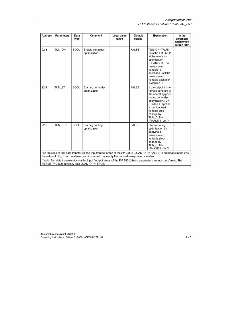
8/11/2019 FM_355-2_e
http://slidepdf.com/reader/full/fm355-2e 205/244
Assignment of DBs
C.1 Instance DB of the FB 52 FMT_PID
Temperature regulator FM 355-2Operating Instructions, Edition 01/2006, A5E00142771-02 C-7
Address Parameters Data
type
Comment Legal value
range
Default
setting
Explanation In the
parameter
assignment
screen form
22.3 TUN_ON BOOL Enable controlleroptimization
FALSE TUN_ON=TRUEputs the FM 355-2at the ready foroptimization(PHASE=1): Themanipulatedvariable isaveraged until themanipulatedvariable excitationis applied.**).
-
22.4 TUN_ST BOOL Starting controller
optimization
FALSE If the setpoint is to
remain constant atthe operating pointduring controlleroptimization,TUN_ ST=TRUE appliesa manipulatedvariable step-change byTUN_DLMN(PHASE 1 - 2) **).
-
22.5 TUN_CST BOOL Starting coolingoptimization
FALSE Starts coolingoptimization byapplying a
manipulatedvariable step-change byTUN_CLMN(PHASE 1 - 2) **).
-
*)In the case of fast data transfer via the input/output areas of the FM 355-2 (LOAD_OP = FALSE) in automatic mode onlythe setpoint SP_RE is transferred and in manual mode only the manual manipulated variable.
**)With fast data transmission via the input / output areas of the FM 355-2 these parameters are not transferred. TheFB FMT_PID automatically sets LOAD_OP = TRUE.

8/11/2019 FM_355-2_e
http://slidepdf.com/reader/full/fm355-2e 206/244
Assignment of DBs
C.1 Instance DB of the FB 52 FMT_PID
Temperature regulator FM 355-2C-8 Operating Instructions, Edition 01/2006, A5E00142771-02
Table C-5 Internal parameters of the instance DB for FMT_PID (controller parameters in PAR structure)
Address Parameters Data
type
Comment Legal value
range
Default
setting
Explanation In the
parameter
assignment
screen form
24.0 vers_no WORD Version, always16#3230, do notchange
W#16#3230 W#16#3230 The parameter vers_nomay not be changed bythe user. It identifies thestart of the controllerparameters, which areread off the FM andstored or uploaded tothe FM withLOAD_PAR=TRUE.
-
26.0 P_SEL BOOL Enableproportionalcomponent
TRUE It is possible to activateand deactivate PIDcomponents individuallyin the PID algorithm.The P-actioncomponent is enabled ifthe input P_SEL is set.
PIDController
26.1 MONERSEL BOOL Monitoring:Process variable= 0
Error signal = 1
FALSE The controllerpossesses a limit valuedetector that can beapplied either for theactual value or for theerror signal. If
MONERSEL is set, theerror signal ismonitored.
Interrupt
Controller
26.2 PID_ON BOOL Enable PID mode TRUE After optimization or inthe case of LOAD_PID= TRUE the PIDparameters areactivated. In the case ofPID_ON = FALSE thePI parameters aretaken.
It may be that withsome process types, in
spite of PID_ON =TRUE only one PIcontroller is designed.
-
26.3 CONZ_ON BOOL Enable controlzone
FALSE TRUE = control zoneenabled
FALSE = control zonedisabled
Controlzone

8/11/2019 FM_355-2_e
http://slidepdf.com/reader/full/fm355-2e 207/244
Assignment of DBs
C.1 Instance DB of the FB 52 FMT_PID
Temperature regulator FM 355-2Operating Instructions, Edition 01/2006, A5E00142771-02 C-9
Address Parameters Data
type
Comment Legal value
range
Default
setting
Explanation In the
parameter
assignment
screen form
28.0 D_EL_SEL INT Input forderivative actionelement
0 to 3, 16, 17 16 In the PID algorithm thederivative actionelement can beconnected to a separateinput This is selected onthe D_EL_SELparameter. 16: Errorsignal 0 to 3: Analoginput 0 to 317: negative actualvalue
Error signalcontroller
30.0 SP_HLM REAL Upper setpoint
limit
> SP_LLM
(physic.variable)
100.0 The setpoint is always
limited to a high and alow limit. The SP_HLMparameter specifies thehigh limit.
Limiting
setpointcontroller
34.0 SP_LLM REAL Setpoint low limit > SP_HLM(physic.variable)
0.0 The setpoint is alwayslimited to a high and alow limit. The SP_LLMparameter specifies thelow limit.
Limitingsetpointcontroller
38.0 H_ALM REAL high limit valueinterrupt
> H_WRN(physic.variable)
100.0 Highest limit formonitoring the actualvalue or the errorsignal.
Interruptcontroller
42.0 H_WRN REAL high limit valuewarning
> H_ALM(physic.variable)
90.0 Second to highest limitfor monitoring the actualvalue or the errorsignal.
Interruptcontroller
46.0 L_WRN REAL low limit valuewarning
> H_WRN ...L_ALM(physic.variable)
10.0 Second to lowest limitfor monitoring the actualvalue or the errorsignal.
Interruptcontroller
50.0 L_ALM REAL low limit valueinterrupt
> L_WRN(physic.variable)
0.0 Lowest limit formonitoring the actualvalue or the errorsignal.
Interruptcontroller
54.0 HYS REAL Hysteresis >= 0.0(physic.variable)
1.0 The parameters can beassigned for ahysteresis to preventthe monitoring displaysfrom flickering.
Interruptcontroller
58.0 DEADB_W REAL Dead band width >= 0.0(physic.variable)
0.0 The error signal isrouted over a deadband. The DEADB_Wparameter determinesthe size of the deadband.
Dead zone
Controller

8/11/2019 FM_355-2_e
http://slidepdf.com/reader/full/fm355-2e 208/244
Assignment of DBs
C.1 Instance DB of the FB 52 FMT_PID
Temperature regulator FM 355-2C-10 Operating Instructions, Edition 01/2006, A5E00142771-02
Address Parameters Data
type
Comment Legal value
range
Default
setting
Explanation In the
parameter
assignment
screen form
62.0 PFAC_SP REAL Proportionalfactor
0.0 ...1.0 1.0 PFAC_SP specifies theeffective proportionalaction element whensetpoints are changed.
PIDController
66.0 GAIN REAL P-actioncoefficient
%/phys.variable
1.0 The GAIN parameterspecifies the controllergain.
The control direction isinverted by means of anegative sign of GAIN.
PIDController
70.0 TI REAL Integration time
(s)
= 0.0 or >=
0.5
3000.0 The TI (integral-action
time) parameterdetermines the dynamicresponse of theintegrator. If TI = 0.0 theintegrator is disabled.
PID
Controller
74.0 TD REAL Derivative-actiontime (s)
= 0.0or > = 1.0
0.0 The TD (rate time)determines the timeaction of the derivativeaction element (D-element). If TD = 0.0,the derivative-actionelement is disabled.
PIDController
78.0 D_F REAL Derivative-action
factor
5.0 ... 10.0 5.0 The time constant
TD/D_F which iseffective for the D-element is limitedinternally to ≥ samplingtime/2
PID
Controller
82.0 LMN_SAFE REAL Safetymanipulatedvariable
-100.0 ...100.0 (%)
0.0 A safety value can beparameterized for themanipulated variable.
Enablingsafetymanipulated variable
Controller
86.0 LMN_HLM REAL Upper limit ofmanipulatedvariable
LMN_LLM ...100.0 (%)
100.0 The manipulatedvariable is alwayslimited to an high and a
low limit. TheLMN_HLM parameterspecifies the high limit.
(this does not apply tostep-action controllerswithout analog positionfeedback).
Limiting
Manipulated variable
Controller

8/11/2019 FM_355-2_e
http://slidepdf.com/reader/full/fm355-2e 209/244
Assignment of DBs
C.1 Instance DB of the FB 52 FMT_PID
Temperature regulator FM 355-2Operating Instructions, Edition 01/2006, A5E00142771-02 C-11
Address Parameters Data
type
Comment Legal value
range
Default
setting
Explanation In the
parameter
assignment
screen form
90.0 LMN_LLM REAL Low limit ofmanipulatedvariable
-100.0 ...LMN_HLM(%)
0.0 The manipulatedvariable is alwayslimited to an high and alow limit. The LMN_LLMparameter specifies thelow limit. (this does notapply to step-actioncontrollers withoutanalog positionfeedback).
Limiting
Manipulated variable
Controller
94.0 MTR_TM REAL Motor actuatingtime (s)
MTR_TM >=0.001
60.0 Limit-to-limit runtime ofthe control valve
(applies to step-actioncontrollers only).
Pulseshaper
Controller
98.0 PULSE_TM REAL Minimum pulsewidth (s)
>= 0.0 0.0 Minimum pulse width(applies to step-actioncontrollers or pulsecontrollers only)
Pulseshaper
Split-rangecontroller/
Pulse-shapercontroller
102.0 BREAK_TM REAL Minimuminterpulse width(s)
>= 0.0 0.0 Minimum interpulsewidth (applies to step-action controllers or
pulse controllers only)
Pulseshaper
Split-range
controllers/pulseshaper
Controllers
106.0 RATIOFAC REAL Ratio factor = 0.0 or0.01 ... 100.0
0.0 Ratio of heatinggain/cooling gain for theprocess.RATIOFAC <> 0.0 hasthe effect:
•
LMN = LMN *RATIOFAC forLMN < 0.0;
•
CON_ZONE 50 %greater
Cooling
110.0 CON_ZONE REAL Control zonewidth
> 0.0
technicalvalue rangephysic. variable)
100.0 If ER >= CON_ZONE,then LMN = LMN_HLM.
If ER <= -CON_ZONE(or-CON_ZONE/RATIOFAC for RATIOFAC<>0.0),then LMN = LMN_LLM.
Controlzone

8/11/2019 FM_355-2_e
http://slidepdf.com/reader/full/fm355-2e 210/244
Assignment of DBs
C.1 Instance DB of the FB 52 FMT_PID
Temperature regulator FM 355-2C-12 Operating Instructions, Edition 01/2006, A5E00142771-02
Address Parameters Data
type
Comment Legal value
range
Default
setting
Explanation In the
parameter
assignment
screen form
114.0 TUN_DLMN REAL Deltamanipulatedvariable forprocessexcitation
-100.0 ...100.0 (%)
20.0 Process excitation forcontroller optimizationtakes place via amanipulated variablestep-change byTUN_LMN
PIDController
118.0 TUN_CLMN REAL Deltamanipulatedvariable forcoolingoptimization
-100.0 ...100.0 (%)
-20.0 Manipulated variablestep-change aftercooling optimization isstarted by TUN_CST.
PIDController
Table C-6 Internal parameters of the instance DB for FMT_PID (output parameters in OUT structure)
Address Parameters Data
type
Comment
German
Legal value
range
Default
setting
Explanation In
parameter
assignment
screen form
122.0 vers_no WORD Version, always16#3230, do notchange
W#16#3230 W#16#3230
The parameter vers_nomay not be changed bythe user. It identifies thestart of the outputparameters which are
read by the module ifREAD_OUT = TRUE isset.
-
124.0 PV REAL Actual value technicalvalue range(physic.variable)
0.0 Effective actual value. -
128.0 LMN REAL Manipulatedvariable
-100.0 ...100.0 (%)
0.0 The effectivemanipulated variablethat is currently in effectis output at the LMNoutput.
In the case of step-
action controllerswithout analog positionfeedback, the unlimitedP- + D-element is outputon the LMN output.
-
132.1 QLMNSAFE BOOL Safety mode FALSE If the QLMNSAFEoutput is set, the safetymanipulated variable isoutput as themanipulated variable.
-
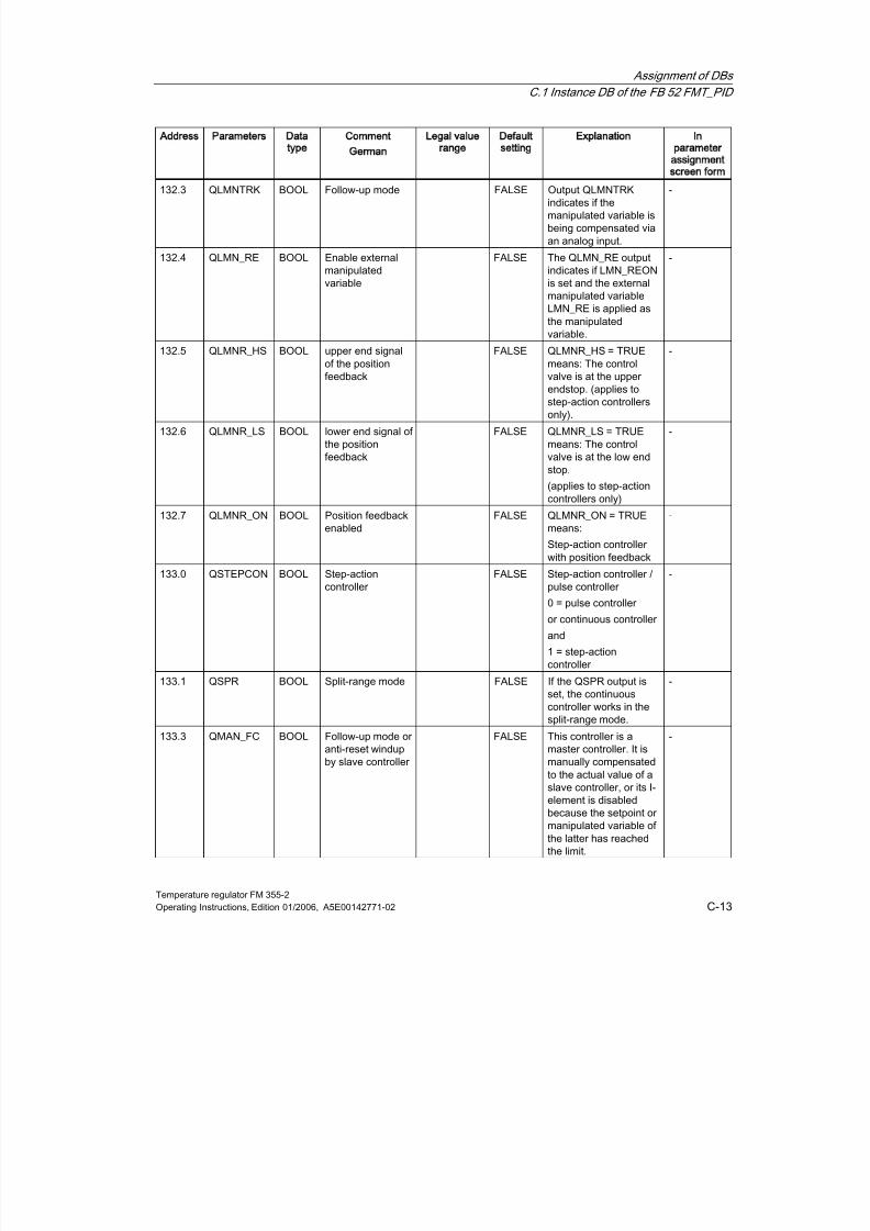
8/11/2019 FM_355-2_e
http://slidepdf.com/reader/full/fm355-2e 211/244
Assignment of DBs
C.1 Instance DB of the FB 52 FMT_PID
Temperature regulator FM 355-2Operating Instructions, Edition 01/2006, A5E00142771-02 C-13
Address Parameters Data
type
Comment
German
Legal value
range
Default
setting
Explanation In
parameter
assignment
screen form
132.3 QLMNTRK BOOL Follow-up mode FALSE Output QLMNTRKindicates if themanipulated variable isbeing compensated viaan analog input.
-
132.4 QLMN_RE BOOL Enable externalmanipulatedvariable
FALSE The QLMN_RE outputindicates if LMN_REONis set and the externalmanipulated variableLMN_RE is applied asthe manipulatedvariable.
-
132.5 QLMNR_HS BOOL upper end signalof the positionfeedback
FALSE QLMNR_HS = TRUEmeans: The controlvalve is at the upperendstop. (applies tostep-action controllersonly).
-
132.6 QLMNR_LS BOOL lower end signal ofthe positionfeedback
FALSE QLMNR_LS = TRUEmeans: The controlvalve is at the low endstop.
(applies to step-actioncontrollers only)
-
132.7 QLMNR_ON BOOL Position feedbackenabled FALSE QLMNR_ON = TRUEmeans:
Step-action controllerwith position feedback
-
133.0 QSTEPCON BOOL Step-actioncontroller
FALSE Step-action controller /pulse controller
0 = pulse controller
or continuous controller
and
1 = step-actioncontroller
-
133.1 QSPR BOOL Split-range mode FALSE If the QSPR output is
set, the continuouscontroller works in thesplit-range mode.
-
133.3 QMAN_FC BOOL Follow-up mode oranti-reset windupby slave controller
FALSE This controller is amaster controller. It ismanually compensatedto the actual value of aslave controller, or its I-element is disabledbecause the setpoint ormanipulated variable ofthe latter has reachedthe limit.
-
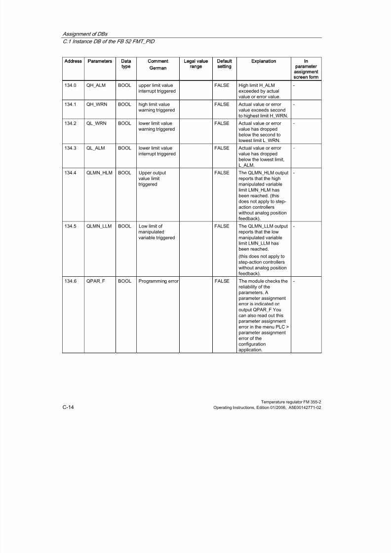
8/11/2019 FM_355-2_e
http://slidepdf.com/reader/full/fm355-2e 212/244
Assignment of DBs
C.1 Instance DB of the FB 52 FMT_PID
Temperature regulator FM 355-2C-14 Operating Instructions, Edition 01/2006, A5E00142771-02
Address Parameters Data
type
Comment
German
Legal value
range
Default
setting
Explanation In
parameter
assignment
screen form
134.0 QH_ALM BOOL upper limit valueinterrupt triggered
FALSE High limit H_ALMexceeded by actualvalue or error value.
-
134.1 QH_WRN BOOL high limit valuewarning triggered
FALSE Actual value or errorvalue exceeds secondto highest limit H_WRN.
-
134.2 QL_WRN BOOL lower limit valuewarning triggered
FALSE Actual value or errorvalue has droppedbelow the second tolowest limit L_WRN.
-
134.3 QL_ALM BOOL lower limit value
interrupt triggered
FALSE Actual value or error
value has droppedbelow the lowest limit,L_ALM.
-
134.4 QLMN_HLM BOOL Upper outputvalue limittriggered
FALSE The QLMN_HLM outputreports that the highmanipulated variablelimit LMN_HLM hasbeen reached. (thisdoes not apply to step-action controllerswithout analog positionfeedback).
-
134.5 QLMN_LLM BOOL Low limit of
manipulatedvariable triggered
FALSE The QLMN_LLM output
reports that the lowmanipulated variablelimit LMN_LLM hasbeen reached.
(this does not apply tostep-action controllerswithout analog positionfeedback).
-
134.6 QPAR_F BOOL Programming error FALSE The module checks thereliability of theparameters. Aparameter assignmenterror is indicated on
output QPAR_F Youcan also read out thisparameter assignmenterror in the menu PLC >parameter assignmenterror of theconfigurationapplication.
-
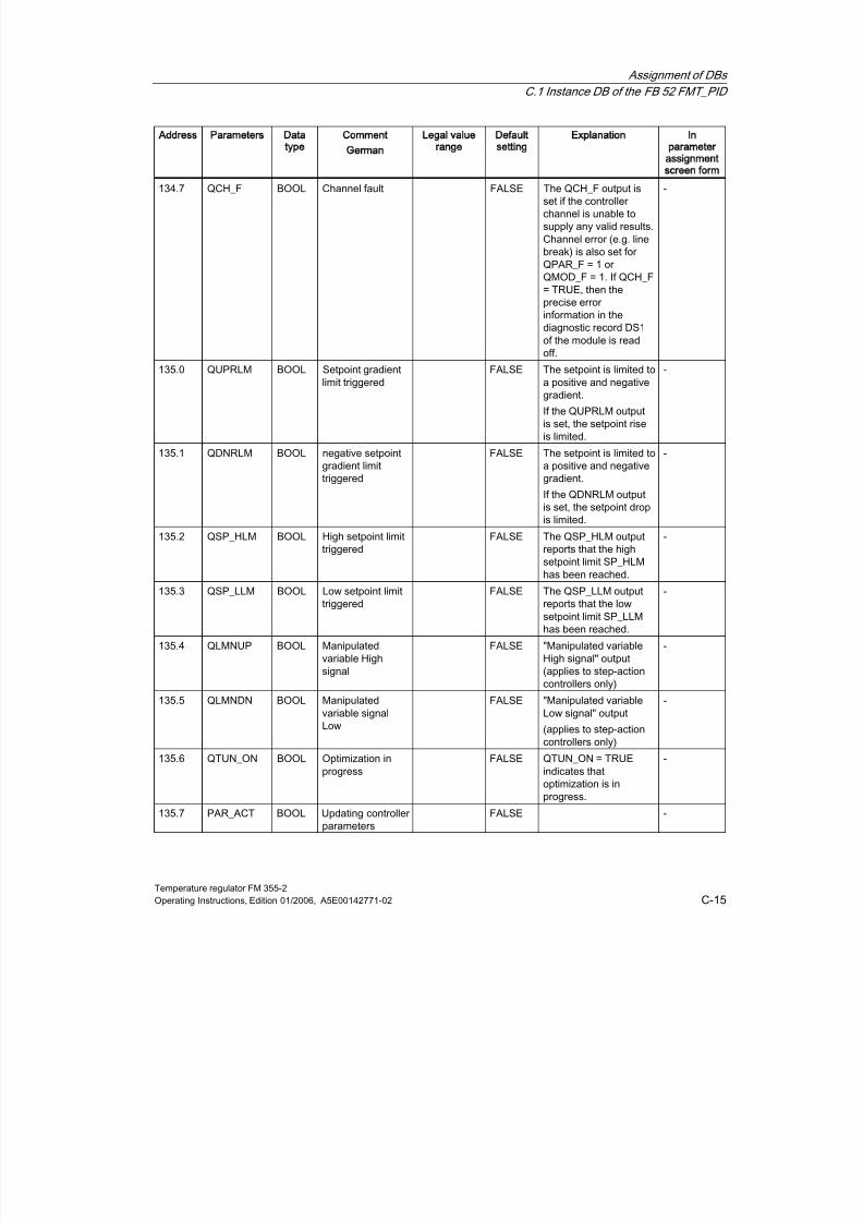
8/11/2019 FM_355-2_e
http://slidepdf.com/reader/full/fm355-2e 213/244

8/11/2019 FM_355-2_e
http://slidepdf.com/reader/full/fm355-2e 214/244
Assignment of DBs
C.1 Instance DB of the FB 52 FMT_PID
Temperature regulator FM 355-2C-16 Operating Instructions, Edition 01/2006, A5E00142771-02
Address Parameters Data
type
Comment
German
Legal value
range
Default
setting
Explanation In
parameter
assignment
screen form
136.0 SP REAL Setpoint technicalvalue range(physic.variable)
0.0 Effective actualsetpoint. *)
-
140.0 ER REAL Error signal technicalvalue range(physic.variable)
0.0 *) -
144.0 DISV REAL Disturbancevariable
-100.0...100.0(%)
0.0 Effective disturbancevariable *)
-
148.0 LMN_A REAL Manipulated
variable A of thesplit-rangefunction / positionfeedback
-100.0...100.0
(%)
0.0 On output "LMN_A" in
the case of continuousor pulse controllers ofmanipulated variable Aof the split-rangefunction is displayedand for step-actioncontrollers with analogposition feedback, theposition feedback isdisplayed there. *)
-
152.0 LMN_B REAL Manipulatedvariable B of thesplit-range
function
-100.0 ...100.0 (%)
0.0 On output "LMN_B" inthe case of continuousor pulse controllers
manipulated variable Bof the split-rangefunction is displayed. *)
-
156.0 PHASE INT Optimizationphases
0..7 0 Indicates the controlleroptimization phases. *)
-
158.0 STATUS_H INT Heatingoptimization status
0 Diagnostics value forinflection pointidentification duringheating optimization *)
-
160.0 STATUS_C INT Coolingoptimization status
0 Diagnostics value forinflection pointidentification duringcooling optimization *)
-
162.0 STATUS_D INT Controller designstatus
0 Diagnostics value forcontroller design duringheating optimization *)
-

8/11/2019 FM_355-2_e
http://slidepdf.com/reader/full/fm355-2e 215/244
Assignment of DBs
C.1 Instance DB of the FB 52 FMT_PID
Temperature regulator FM 355-2Operating Instructions, Edition 01/2006, A5E00142771-02 C-17
Address Parameters Data
type
Comment
German
Legal value
range
Default
setting
Explanation In
parameter
assignment
screen form
164.0 ZONE_TUN WORD Controllerchannels whichcan be grouped inone zone for thepurpose of paralleloptimization
W#16#0 In HEX code, each oneof the four digitsrepresents one channel,arranged in thefollowing order from leftto right: Channel 0, 1, 2,3 ZONE_TUN = 0means that the channelselected will not beoptimized together withother channels. Avalue <> 0000 shows -
in each case with a 1 -the channels which willbe optimized as agroup. *)
*)With fast data transmission via the input / output areas of the FM 355-2 (READ_OUT = FALSE), these parameters arenot transferred.
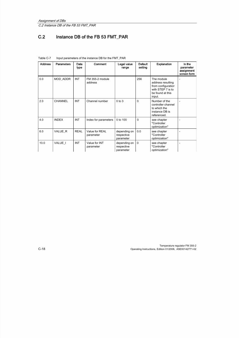
8/11/2019 FM_355-2_e
http://slidepdf.com/reader/full/fm355-2e 216/244
Assignment of DBs
C.2 Instance DB of the FB 53 FMT_PAR
Temperature regulator FM 355-2C-18 Operating Instructions, Edition 01/2006, A5E00142771-02
C.2
C2Instance DB of the FB 53 FMT_PAR
Table C-7 Input parameters of the instance DB for the FMT_PAR
Address Parameters Data
type
Comment Legal value
range
Default
setting
Explanation In the
parameter
assignment
screen form
0.0 MOD_ADDR INT FM 355-2 moduleaddress
256 The moduleaddress resultingfrom configurationwith STEP 7 is tobe found at thisinput.
-
2.0 CHANNEL INT Channel number 0 to 3 0 Number of thecontroller channelto which theinstance DB isreferenced.
-
4.0 INDEX INT Index for parameters 0 to 100 0 see chapter"Controlleroptimization"
-
6.0 VALUE_R REAL Value for REALparameter
depending onrespectiveparameter
0.0 see chapter"Controlleroptimization"
-
10.0 VALUE_I INT Value for INTparameter
depending onrespectiveparameter
0 see chapter"Controlleroptimization"
-
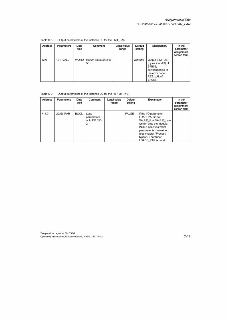
8/11/2019 FM_355-2_e
http://slidepdf.com/reader/full/fm355-2e 217/244
Assignment of DBs
C.2 Instance DB of the FB 53 FMT_PAR
Temperature regulator FM 355-2Operating Instructions, Edition 01/2006, A5E00142771-02 C-19
Table C-8 Output parameters of the instance DB for the FMT_PAR
Address Parameters Data
type
Comment Legal value
range
Default
setting
Explanation In the
parameter
assignment
screen form
12.0 RET_VALU WORD Return value of SFB53
W#16#0 Output STATUS(bytes 2 and 3) ofSFB53;corresponding tothe error codeRET_VAL ofSFC58
-
Table C-9 Output parameters of the instance DB for the FB FMT_PAR
Address Parameters Data
type
Comment Legal value
range
Default
setting
Explanation In the
parameter
assignment
screen form
+14.0 LOAD_PAR BOOL Loadparametersonto FM 355-2
FALSE If the I/O parameterLOAD_PAR is set,VALUE_R or VALUE_I arewritten onto the module.INDEX specifies whichparameter is overwritten
(see chapter "Processtypes"). ThereafterLOADS_PAR is reset.
-
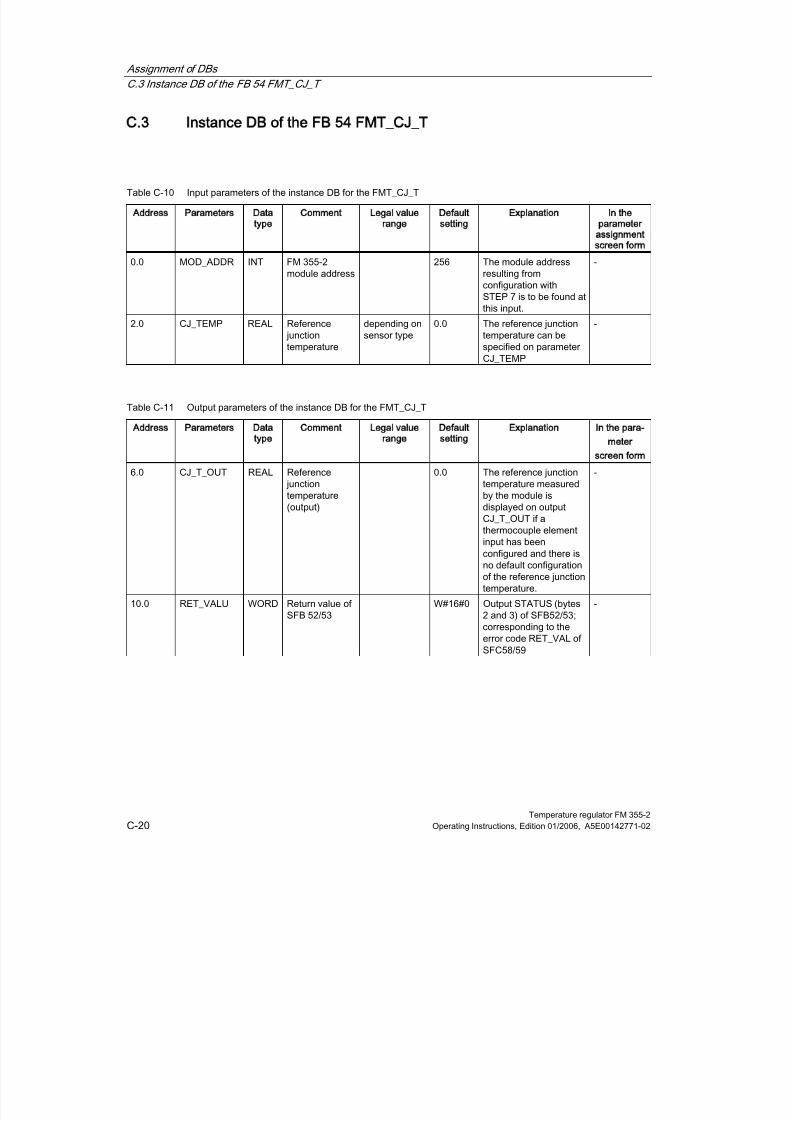
8/11/2019 FM_355-2_e
http://slidepdf.com/reader/full/fm355-2e 218/244
Assignment of DBs
C.3 Instance DB of the FB 54 FMT_CJ_T
Temperature regulator FM 355-2C-20 Operating Instructions, Edition 01/2006, A5E00142771-02
C.3
C3Instance DB of the FB 54 FMT_CJ_T
Table C-10 Input parameters of the instance DB for the FMT_CJ_T
Address Parameters Data
type
Comment Legal value
range
Default
setting
Explanation In the
parameter
assignment
screen form
0.0 MOD_ADDR INT FM 355-2module address
256 The module addressresulting fromconfiguration withSTEP 7 is to be found atthis input.
-
2.0 CJ_TEMP REAL Reference junctiontemperature
depending onsensor type
0.0 The reference junctiontemperature can bespecified on parameterCJ_TEMP
-
Table C-11 Output parameters of the instance DB for the FMT_CJ_T
Address Parameters Data
type
Comment Legal value
range
Default
setting
Explanation In the para-
meter
screen form
6.0 CJ_T_OUT REAL Reference junctiontemperature(output)
0.0 The reference junctiontemperature measuredby the module isdisplayed on outputCJ_T_OUT if athermocouple elementinput has beenconfigured and there isno default configurationof the reference junctiontemperature.
-
10.0 RET_VALU WORD Return value ofSFB 52/53
W#16#0 Output STATUS (bytes2 and 3) of SFB52/53;
corresponding to theerror code RET_VAL ofSFC58/59
-
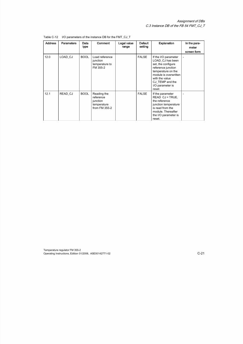
8/11/2019 FM_355-2_e
http://slidepdf.com/reader/full/fm355-2e 219/244
Assignment of DBs
C.3 Instance DB of the FB 54 FMT_CJ_T
Temperature regulator FM 355-2Operating Instructions, Edition 01/2006, A5E00142771-02 C-21
Table C-12 I/O parameters of the instance DB for the FMT_CJ_T
Address Parameters Data
type
Comment Legal value
range
Default
setting
Explanation In the para-
meter
screen form
12.0 LOAD_CJ BOOL Load reference junctiontemperature toFM 355-2
FALSE If the I/O parameterLOAD_CJ has beenset, the configurereference junctiontemperature on themodule is overwrittenwith the valueCJ_TEMP and theI/O parameter isreset.
-
12.1 READ_CJ BOOL Reading the
reference junctiontemperaturefrom FM 355-2
FALSE If the parameter
READ_CJ = TRUE,the reference junction temperatureis read from themodule. Thereafterthe I/O parameter isreset.
-

8/11/2019 FM_355-2_e
http://slidepdf.com/reader/full/fm355-2e 220/244
Assignment of DBs
C.4 Instance DB of the FB 55 FMT_DS 1
Temperature regulator FM 355-2C-22 Operating Instructions, Edition 01/2006, A5E00142771-02
C.4
C4Instance DB of the FB 55 FMT_DS 1
Table C-13 Input parameters of the instance DB for the FMT_DS1
Address Parameters Data
type
Comment Legal value
range
Default
setting
Explanation In parameter
assignment
screen
0.0 MOD_ADDR INT Module addressFM 355-2
256 The moduleaddress thatresulted from theconfiguration withSTEP 7 is given at
this input.
-
Table C-14 Output parameters of the instance DB for the FMT_DS1
Address Parameters Data type Comment Legal value
range
Default
setting
Explanation In parameter
assignment
screen
2.0 DS1 STRUCT Diagnostic datarecord DS1
includes bytes 0 to12
-
16.0 RET_VALU INT Return value ofSFB 52
W#16#0 Output STATUS(bytes 2 and 3) of
SFB52;corresponding tothe error codeRET_VAL ofSFC59
-
Table C-15 I/O parameters of the instance DB for the FMT_DS1
Address Parameters Data
type
Comment Legal value
range
Default
setting
Explanation In parameter
assignment
screen
18.0 READ_DS1 BOOL Reading DS1 from
FM 355-2
FALSE If parameter
READ_DS1 =TRUE, thendiagnostic datarecord DS1 is readoff the FM 355-2and written to theDS1 structure ofthe instance DB.Thereafter the I/Oparameter is reset.
-

8/11/2019 FM_355-2_e
http://slidepdf.com/reader/full/fm355-2e 221/244
Assignment of DBs
C.5 Instance DB of the FB 56 FMT_TUN
Temperature regulator FM 355-2Operating Instructions, Edition 01/2006, A5E00142771-02 C-23
C.5
C5Instance DB of the FB 56 FMT_TUN
Table C-16 Input parameters of the instance DB for the FMT_TUN
Address Parameters Data
type
Comment Legal value
range
Default
setting
Explanation In parameter
assignment
screen
0.0 MOD_ADDR INT Module addressFM 355-2
256 The module addressresulting fromconfiguration withSTEP 7 is to be foundat this input.
-
2.0 CHANNEL INT Channelnumber 0 to 3 0 The number of thecontroller channel towhich the instance DBis referenced isconfigured at input"Channel number".
-
Table C-17 Output parameters of the instance DB for the FMT_TUN
Address Parameters Data
type
Comment Legal value
range
Default
setting
Explanation In the para-
meter
screen form
4.0 PI_GAIN REAL PI controllergain
0.0 PI controllerparameters
-
8.0 PI_TI REAL PI controllerintegration time(s)
0.0 PI controllerparameters
-
12.0 PID_GAIN REAL PID controllergain
0.0 PID controllerparameters
-
16.0 PID_TI REAL PID controllerintegration time
0.0 PID controllerparameters
-
20.0 PID_TD REAL PID controllerderivative time
(s)
0.0 PID controllerparameters
-
24.0 SAV_PFAC REAL Old proportionalfactor
0.0 Saved controllerparameters
-
28.0 SAV_GAIN REAL Old controllergain
0.0 Saved controllerparameters
-
32.0 SAV_TI REAL Old controllerintegration time(s)
0.0 Saved controllerparameters
-
36.0 SAV_TD REAL Old controllerderivative time(s)
0.0 Saved controllerparameters
-

8/11/2019 FM_355-2_e
http://slidepdf.com/reader/full/fm355-2e 222/244
Assignment of DBs
C.5 Instance DB of the FB 56 FMT_TUN
Temperature regulator FM 355-2C-24 Operating Instructions, Edition 01/2006, A5E00142771-02
Address Parameters Data
type
Comment Legal value
range
Default
setting
Explanation In the para-
meter
screen form
40.0 SAV_D_F REAL Old derivative-action factor
0.0 Saved controllerparameters
-
44.0 SAV_RATI REAL Old ratio factor 0.0 Saved controllerparameters
-
48.0 SAV_CONZ REAL Old control zonewidth
0.0 Saved controllerparameters
-
52.0 SAV_PSEL BOOL Old value ofP_SEL
FALSE Saved controllerparameters
-
52.1 SAV_CZON BOOL Old value forcontrol zoneenabled
FALSE Saved controllerparameters
-
54.0 RET_VALU WORD Return value ofSFB 52
W#16#0 Output STATUS(bytes 2 and 3) ofSFB52; correspondingto the error codeRET_VAL of SFC59
-
Table C-18 Input parameters of the instance DB for the FMT_TUN
Address Parameters Data
type
Comment Legal value
range
Default
setting
Explanation In the para-
meter
screen form
56.0 READ_OUT BOOL Reading outputparametersfrom the FM355-2
FALSE If the I/O parameterREAD_OUT is set, theoutput parameters areread off the FM 355-2.
-
Note
The parameters between the addresses 56.0 and 152.0 are described in the table "Internalparameters of the instance DB for the FMT_PID (output parameter in the structure OUT)".

8/11/2019 FM_355-2_e
http://slidepdf.com/reader/full/fm355-2e 223/244
Assignment of DBs
C.5 Instance DB of the FB 56 FMT_TUN
Temperature regulator FM 355-2Operating Instructions, Edition 01/2006, A5E00142771-02 C-25
Table C-19 Internal parameters of the instance DB for the FMT_TUN (in OUT structure)
Address Parameters Data
type
Comment Legal value
range
Default
setting
Explanation In the para-
meter
screen form
152.0 GAIN_P REAL Process gain (phys.variable) /%
0.0 Identified processgain. In the case ofprocess type I,GAIN_P tends to beestimated too low.
-
156.0 TU REAL Delay time (s) Scan time ≥ 3* 0.0 Identified processdelay.
-
160.0 TA REAL Delay time (s) ≥ 0.0 0.0 Identified processdelay.
In the case of processtype 1, TA tends to beestimated too low.
-
164.0 KIG REAL Maximum actualvalue rise atmanipulatedvariableexcitation from 0to 100%.
(phys.variable) /s
0.0 Maximum possiblegain of the actualvalue.
GAIN_P = 0.01 * KIG* TA
-
168.0 N_PTN REAL Process order 1.01 ... 10.0 0.0 Order of the process"Non-integer values"are also possible.
-
172.0 TM_LAG_P REAL Time constant ofa PTN model ≥ 0.0 0.0 Time constant of aPTN model.
(practical values forN_PTN>=2 only).
-
176.0 T_P_INF REAL Time toinflection point(s)
≥ 0.0 0.0 Time from processexcitation to inflectionpoint.
-
180.0 P_INF REAL Actual value atinflection point -PV0 - PV0
(phys.variable)
0.0 Change in actualvalue from processexcitation to inflectionpoint.
-
184.0 LMN0 REAL Manipulated
variable at thebeginning ofoptimization
-100.0 ... 100.0
(%)
0.0 Is established in
phase 1 (average)
-
188.0 PV0 REAL Actual value atthe beginning ofoptimization
(phys.variable)
0.0 Is established inphase 1 (average).
-
192.0 PVDT0 REAL Actual valuegain at thebeginning ofoptimization
(phys.variable) /s
0.0 Sign is adapted. -
196.0 PVDT REAL Current actualvalue gain
(phys.variable) /s
0.0 Sign is adapted. -

8/11/2019 FM_355-2_e
http://slidepdf.com/reader/full/fm355-2e 224/244
Assignment of DBs
C.5 Instance DB of the FB 56 FMT_TUN
Temperature regulator FM 355-2C-26 Operating Instructions, Edition 01/2006, A5E00142771-02
Address Parameters Data
type
Comment Legal value
range
Default
setting
Explanation In the para-
meter
screen form
200.0 PVDT_MAX REAL Max. actualvalue change
(phys.variable) /s
0.0 Maximum derivativeof the actual value atthe point of inflection(sign adapted, always> 0); is used tocalculate TU and KIG.
-
204.0 NOI_PVDT REAL Proportion ofnoise inPVDT_MAX in%
0.0 The larger the noisefraction, the lessprecise (softer) arethe controllerparameters.
-
208.0 NOISE_PV REAL Absolute actual
value noise
(phys.
variable) /s
0.0 The difference
between maximumand minimum actualvalue in phase 1.
-
212.0 FIL_CYC INT Number ofcycles of themean value filter
1 ... 1024 0 The actual value isaveraged overFIL_CYC cycles.When required,FIL_CYC isautomatically raisedfrom 1 max. 1024.
-
214.0 POI_CMAX INT Maximumnumber ofcycles after
inflection point
≥ 0 0 This time is used tofind another (i.e.better) inflection point
in case of measuringnoise. Only then isoptimizationcompleted.
-
216.0 POI_CYCL INT Number ofcycles afterinflection point
≥ 0 0 The aforementionedparameters are to befound in the OUTstructure followingSAV_CZON
-
See also
Instance DB of the FB 52 FMT_PID (Page C-1)

8/11/2019 FM_355-2_e
http://slidepdf.com/reader/full/fm355-2e 225/244
Assignment of DBs
C.6 Instance DB of the FB 57 FMT_PV
Temperature regulator FM 355-2Operating Instructions, Edition 01/2006, A5E00142771-02 C-27
C.6
C6Instance DB of the FB 57 FMT_PV
Table C-20 Input parameters of the instance DB for the FMT_PV
Address Parameters Data type Comment Legal value
range
Default
setting
Explanation In the para-
meter
screen form
0.0 S_AION ARRAY[0..3] ofBOOL
Switch:Simulation ofthe analoginput value viaPV_SIM
FALSE If, e.g. theS_AION[1] switchis set to TRUE,then the valuePV_SIM[1] is usedinstead of theanalog input value1 of the module
(see figure inchapter " The FM57 FMT_PVfunction block").
-
2.0 S_PVON ARRAY[0..3] ofBOOL
Switch:Simulation ofthepreprocessedanalog inputvalue viaPV_SIM
FALSE If, e.g. theS_PVON[1] switchis set to TRUE,then the valuePV_SIM[1] is usedinstead of thepreprocessedanalog input value1 of the module
(see figure inchapter " The FM57 FMT_PVfunction block").
-
4.0 PV_SIM ARRAY[0..3] ofREAL
Simulationvalue for theanalog input
0.0 to 20.0 [mA]or -1500 to+10000 [mV] ortechnical valuerange
0.0 For example, thesimulation value foranalog input 1 isspecified at thePV_SIM [1] input. IfS_PVON = TRUE,then thepreprocessedanalog input valueis specified in thiscase. If S_PVON =FALSE andS_AION = TRUEthen the analoginput value, whichis transformed intoa preprocessedvalue by means ofthe preprocessingfunctions, isspecified in mA ormV.
-
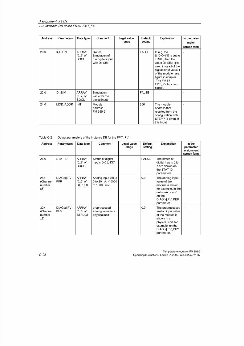
8/11/2019 FM_355-2_e
http://slidepdf.com/reader/full/fm355-2e 226/244
Assignment of DBs
C.6 Instance DB of the FB 57 FMT_PV
Temperature regulator FM 355-2C-28 Operating Instructions, Edition 01/2006, A5E00142771-02
Address Parameters Data type Comment Legal value
range
Default
setting
Explanation In the para-
meter
screen form
20.0 S_DION ARRAY[0..7] ofBOOL
Switch:Simulation ofthe digital inputwith DI_SIM
FALSE If, e.g. theS_DION[1] is set toTRUE, then thevalue DI_SIM[1] isused instead of thedigital input value 1of the module (seefigure in chapter"The FM 57FMT_PV functionblock".
-
22.0 DI_SIM ARRAY
[0..7] ofBOOL
Simulation
value for thedigital input
FALSE -
24.0 MOD_ADDR INT ModuleaddressFM 355-2
256 The moduleaddress thatresulted from theconfiguration withSTEP 7 is given atthis input.
-
Table C-21 Output parameters of the instance DB for the FMT_PV
Address Parameters Data type Comment Legal value
range
Default
setting
Explanation In the
parameter
assignment
screen form
26.0 STAT_DI ARRAY[0..7] ofBOOL
Status of digitalinputs DI0 to DI7
FALSE The states ofdigital inputs 0 to7 are shown onthe STAT_DIparameters.
-
28+(Channelnumberx8)
DIAG[x].PV_ PER
ARRAY[0..3] ofSTRUCT
Analog input value0 to 20mA; -10000to 10000 mV
0.0 The analog inputvalue of themodule is shown,for example, in theunits mA or mV,on theDIAG[x].PV_PERparameter.
-
32+(Channelnumberx8)
DIAG[x].PV_ PHY
ARRAY[0..3] ofSTRUCT
preprocessedanalog value in aphysical unit
0.0 The preprocessedanalog input valueof the module isshown in aphysical unit, forexample, on theDIAG[x].PV_PHYparameter.
-
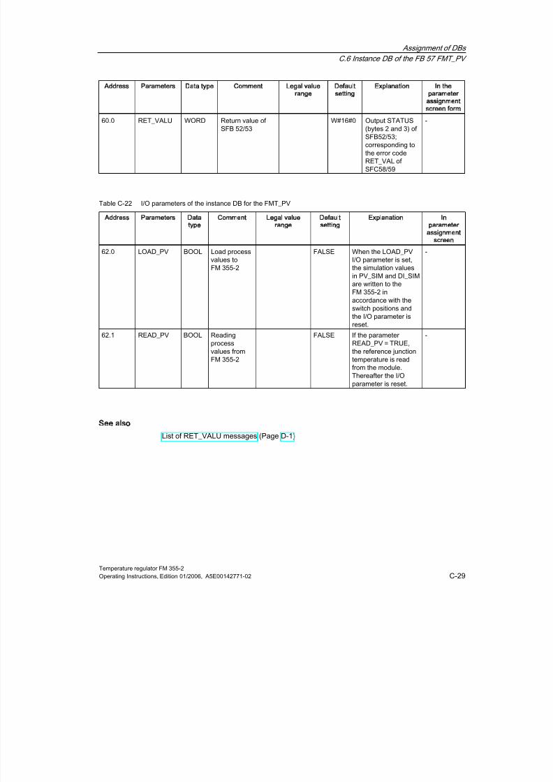
8/11/2019 FM_355-2_e
http://slidepdf.com/reader/full/fm355-2e 227/244
Assignment of DBs
C.6 Instance DB of the FB 57 FMT_PV
Temperature regulator FM 355-2Operating Instructions, Edition 01/2006, A5E00142771-02 C-29
Address Parameters Data type Comment Legal value
range
Default
setting
Explanation In the
parameter
assignment
screen form
60.0 RET_VALU WORD Return value ofSFB 52/53
W#16#0 Output STATUS(bytes 2 and 3) ofSFB52/53;corresponding tothe error codeRET_VAL ofSFC58/59
-
Table C-22 I/O parameters of the instance DB for the FMT_PV
Address Parameters Data
type
Comment Legal value
range
Default
setting
Explanation In
parameter
assignment
screen
62.0 LOAD_PV BOOL Load processvalues toFM 355-2
FALSE When the LOAD_PVI/O parameter is set,the simulation valuesin PV_SIM and DI_SIMare written to theFM 355-2 inaccordance with theswitch positions andthe I/O parameter isreset.
-
62.1 READ_PV BOOL Readingprocessvalues fromFM 355-2
FALSE If the parameterREAD_PV = TRUE,the reference junctiontemperature is readfrom the module.Thereafter the I/Oparameter is reset.
-
See also
List of RET_VALU messages (Page D-1)

8/11/2019 FM_355-2_e
http://slidepdf.com/reader/full/fm355-2e 228/244
Assignment of DBs
C.6 Instance DB of the FB 57 FMT_PV
Temperature regulator FM 355-2C-30 Operating Instructions, Edition 01/2006, A5E00142771-02

8/11/2019 FM_355-2_e
http://slidepdf.com/reader/full/fm355-2e 229/244
Temperature regulator FM 355-2Operating Instructions, Edition 01/2006, A5E00142771-02 D-1
DList of RET_VALU messages
D
D.1
D1
List of RET_VALU messages
RET_VALU messages
JOB_ERR
(Hex)
JOB_ERR
(Dec)
JOB_ERR
(Int)
Meaning
7000 28672 -32624 First call with REQ=0: no data transmission active; BUSY hasthe value 0.
7001 28673 -32624 First call with REQ=1: data transmission initiated; BUSY hasthe value 1.
7002 28674 -32624 Interim call (REQ irrelevant). Data transmission alreadyactive; BUSY has the value 1.
8090 32912 -32624 Specified logical base address invalid: There is no assignmentin the SDB1/SDB2x, or it is not a base address.
80A0 32928 -32608 Negative acknowledgment when reading from the module.Module was removed during the read operation or the moduleis defective.
80A1 32929 -32607 Negative acknowledgment when writing to the module.Module was removed during the write operation or the moduleis defective.
80A2 32930 -32606 DP protocol error at layer 2
80A3 32931 -32605 DP protocol error in user interface/user
80A4 32932 -32604 Communication bus error
80B1 32945 -32591 Incorrect length specification. FM_TYPE parameter in channelDB not set correctly for the module in use.
80B2 32946 -32590 The configured slot is not being used.
80B3 32947 -32589 Actual module type is not match configured module type.
80C0 32960 -32576 Module data not ready for reading.
80C1 32961 -32575 Data of a write job of the same type have not yet beenprocessed by the module.
80C2 32962 -32574 The module is currently processing the maximum possiblenumber of jobs.
80C3 32963 -32573 Required resources (memory etc.) currently occupied.
80C4 32964 -32572 Communication error
80C5 32965 -32571 Distributed I/O not available.
80C6 32966 -32570 Priority class abort (restart or background).
8522 34082 -31454 Channel DB or parameter DB too short. The data cannot beread off the DB. (Write job)

8/11/2019 FM_355-2_e
http://slidepdf.com/reader/full/fm355-2e 230/244
List of RET_VALU messages
D.1 List of RET_VALU messages
Temperature regulator FM 355-2D-2 Operating Instructions, Edition 01/2006, A5E00142771-02
JOB_ERR
(Hex)
JOB_ERR
(Dec)
JOB_ERR
(Int)
Meaning
8532 34098 -31438 DB number of the parameter DBs too high. (Write job)
853A 34106 -31430 Parameter DB not present. (Write job)
8544 34116 -31420 Error at n-th (n > 1) read access to a DB after an error hasoccurred. (Write job)
8723 34595 -30941 Channel DB or parameter DB too short. The data cannot bewritten to the DB. (Read job)
8730 34608 -30928 Parameter DB in the CPU is write protected. The data cannotbe written to the DB (read job)
8732 34610 -30926 DB number of the parameter DBs too high (Read job)
873A 34618 -30918 Parameter DB not present. (Read job)
8745 34629 -30907 Error at n-th (n > 1) write access to a DB after an error hasoccurred. (Read job)
80ff 33023 -32513 Incorrect index specification with block FMT_PAR
Errors 80A2..80A4 and 80Cx are temporary, i.e. after a waiting period they can be eliminated withoutany action on your part. Messages of the 7xxx form indicate temporary operating states ofcommunication.

8/11/2019 FM_355-2_e
http://slidepdf.com/reader/full/fm355-2e 231/244
Temperature regulator FM 355-2Operating Instructions, Edition 01/2006, A5E00142771-02 E-1
EList of abbreviations
E
E.1
E1
List of abbreviations
Abbreviations
The parameter names of FMT_PID and FMT_TUN are used in the text in a similar way toabbreviations. The following table shows the assignment to the parameters of the FBs. The"Structure" column remains empty if the parameter is not to be found in a structure.
Abbreviation Explanation FB Structure
BREAK_TM Minimum break time [s] FMT_PID PAR
COM_RST Cold restart FMT_PID -
CON_ZONE Control zone width FMT_PID PAR
CONZ_ON Enable control zone FMT_PID PAR
D_EL_SEL Selection of the input for derivative action element FMT_PID PAR
D_F Derivative-action factor FMT_PID PAR
DEADB_W Dead band width FMT_PID PARDISV Disturbance variable FMT_PID OUT
ER Error signal FMT_PID OUT
FIL_CYC Number of cycles of the mean value filter FMT_TUN OUT
GAIN Controller gain (proportional coefficient) FMT_PID PAR
GAIN_P Process gain FMT_TUN OUT
H_ALM upper limit value interrupt FMT_PID PAR
H_WRN upper limit value warning FMT_PID PAR
HYS Hysteresis FMT_PID PAR
KIG Maximum actual value rise at manipulated variableexcitation from 0 to 100% [1/s]
FMT_TUN OUT
L_ALM low limit value interrupt FMT_PID PAR
L_WRN lower limit value warning FMT_PID PAR
LMN Manipulated variable FMT_PID OUT
LMN_A Manipulated variable A of the split-range function FMT_PID OUT
LMN_B Manipulated variable B of the split-range function FMT_PID OUT
LMN_DN Manipulated variable signal Low operation (for step-actioncontrollers only).
FMT_PID OP
LMN_HLM Upper limit of manipulated variable FMT_PID PAR
LMN_LLM Lower limit of manipulated variable FMT_PID PAR
LMN_RE external manipulated variable FMT_PID OP

8/11/2019 FM_355-2_e
http://slidepdf.com/reader/full/fm355-2e 232/244
List of abbreviations
E.1 List of abbreviations
Temperature regulator FM 355-2E-2 Operating Instructions, Edition 01/2006, A5E00142771-02
Abbreviation Explanation FB Structure
LMN_REON enable external manipulated variable (manual mode) FMT_PID OP
LMN_UP Manipulated variable signal High operation (for step-actioncontrollers only)
FMT_PID OP
LMN0 Manipulated variable at the beginning of optimization FMT_TUN OUT
LMNRHSRE upper end signal of the position feedback FMT_PID OP
LMNRLSRE lower end signal of the position feedback FMT_PID OP
LMNS_ON Enable operation of manipulated variables (for step-actioncontrollers only) (manual mode)
FMT_PID OP
LMNTRKON Correction of the manipulated variable via analog input FMT_PID OP
LOAD_OP Download operator parameters to FM 355-2 FMT_PID -
LOAD_PAR Download controller parameters to FM 355-2 FMT_PID -
LOAD_PID Load optimized PI/PID parameters FMT_PID OP
MONERSEL Monitoring: Process variable = 0; error signal = 1 FMT_PID PARMTR_TM Motor actuating time [s] FMT_PID PAR
N_PTN Process order FMT_TUN OUT
NOI_PVDT Proportion of noise in PVDT_MAX in % FMT_TUN OUT
NOISE_PV absolute noise in actual value FMT_TUN OUT
P_INF Actual value at inflection point - PV0 FMT_TUN OUT
P_SEL Enable proportional component FMT_PID PAR
PFAC_SP Proportional factor for setpoint changes FMT_PID PAR
PHASE Phase display of controller optimization FMT_PID OUT
PID_ON Enable PID mode FMT_PID PAR
POI_CMAX maximum number of cycles after inflection point FMT_TUN OUTPOI_CYCL Number of cycles after inflection point FMT_TUN OUT
PULSE_TM Minimum pulse duration [s] FMT_PID PAR
PV Actual value FMT_PID OUT
PV0 Actual value at the beginning of optimization FMT_TUN OUT
PVDT current actual value gain [1/s] FMT_TUN OUT
PVDT_MAX Max. change in the actual value per second [1/s] FMT_TUN OUT
PVDT0 Actual value gain at the beginning of optimization [1/s] FMT_TUN OUT
QDNRLM negative gain limitation of the setpoint triggered FMT_PID OUT
QH_ALM upper limit value interrupt triggered FMT_PID OUT
QH_WRN upper limit value warning triggered FMT_PID OUT
QL_ALM lower limit value interrupt triggered FMT_PID OUT
QL_WRN lower limit value warning triggered FMT_PID OUT
QLMN_HLM Upper manipulated variable limit triggered FMT_PID OUT
QLMN_LLM lower manipulated variable limit triggered FMT_PID OUT
QLMN_RE external manipulated variable enabled FMT_PID OUT
QLMNDN Manipulated variable signal Low output (pulse and step-action controllers)
FMT_PID OUT
QLMNR_HS upper end signal of the position feedback FMT_PID OUT
QLMNR_LS lower end signal of the position feedback FMT_PID OUT
QLMNSAFE Safety mode FMT_PID OUT
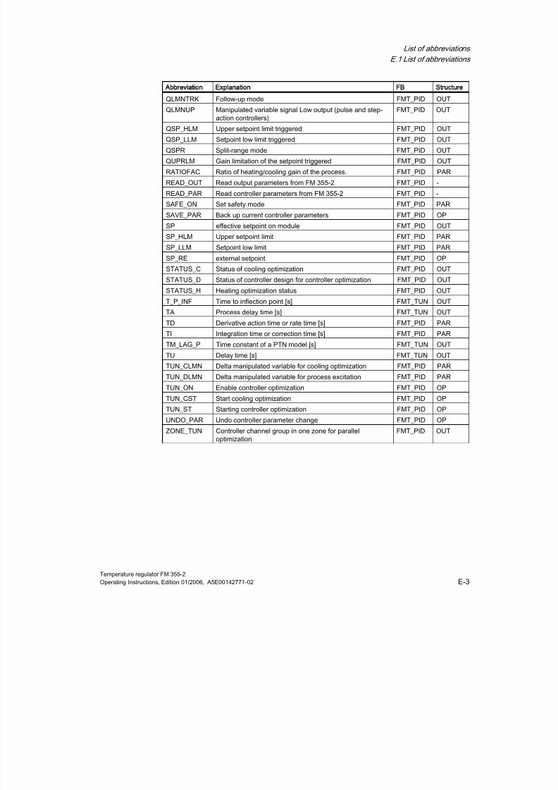
8/11/2019 FM_355-2_e
http://slidepdf.com/reader/full/fm355-2e 233/244
List of abbreviations
E.1 List of abbreviations
Temperature regulator FM 355-2Operating Instructions, Edition 01/2006, A5E00142771-02 E-3
Abbreviation Explanation FB Structure
QLMNTRK Follow-up mode FMT_PID OUT
QLMNUP Manipulated variable signal Low output (pulse and step-action controllers)
FMT_PID OUT
QSP_HLM Upper setpoint limit triggered FMT_PID OUT
QSP_LLM Setpoint low limit triggered FMT_PID OUT
QSPR Split-range mode FMT_PID OUT
QUPRLM Gain limitation of the setpoint triggered FMT_PID OUT
RATIOFAC Ratio of heating/cooling gain of the process. FMT_PID PAR
READ_OUT Read output parameters from FM 355-2 FMT_PID -
READ_PAR Read controller parameters from FM 355-2 FMT_PID -
SAFE_ON Set safety mode FMT_PID PAR
SAVE_PAR Back up current controller parameters FMT_PID OP
SP effective setpoint on module FMT_PID OUT
SP_HLM Upper setpoint limit FMT_PID PAR
SP_LLM Setpoint low limit FMT_PID PAR
SP_RE external setpoint FMT_PID OP
STATUS_C Status of cooling optimization FMT_PID OUT
STATUS_D Status of controller design for controller optimization FMT_PID OUT
STATUS_H Heating optimization status FMT_PID OUT
T_P_INF Time to inflection point [s] FMT_TUN OUT
TA Process delay time [s] FMT_TUN OUT
TD Derivative action time or rate time [s] FMT_PID PAR
TI Integration time or correction time [s] FMT_PID PARTM_LAG_P Time constant of a PTN model [s] FMT_TUN OUT
TU Delay time [s] FMT_TUN OUT
TUN_CLMN Delta manipulated variable for cooling optimization FMT_PID PAR
TUN_DLMN Delta manipulated variable for process excitation FMT_PID PAR
TUN_ON Enable controller optimization FMT_PID OP
TUN_CST Start cooling optimization FMT_PID OP
TUN_ST Starting controller optimization FMT_PID OP
UNDO_PAR Undo controller parameter change FMT_PID OP
ZONE_TUN Controller channel group in one zone for paralleloptimization
FMT_PID OUT

8/11/2019 FM_355-2_e
http://slidepdf.com/reader/full/fm355-2e 234/244
List of abbreviations
E.1 List of abbreviations
Temperature regulator FM 355-2E-4 Operating Instructions, Edition 01/2006, A5E00142771-02

8/11/2019 FM_355-2_e
http://slidepdf.com/reader/full/fm355-2e 235/244
Temperature regulator FM 355-2Operating Instructions, Edition 01/2006, A5E00142771-02 F-1
FFurther Information
F
F.1
F1
Literature
Supplementary references
You will find the basics of control engineering described in the following books:
Title Author Order number
From process to closed-loopcontrol
Gißler/Schmid A19100-L531-F196
ISBN 3-8009-1551-0
Closed-loop control withSIMATIC S5
Basics
Siemens E80850-C331-X-A2
Closed-loop control withSIMATIC
Pratice Manual for Closed-loopControl with SIMATIC S7 andSIMATIC PCS7
Müller, Jürgen A19100-L531-B796
ISBN 3-89578-147-9
Modifying the System DuringOperation via CiR
Siemens Cannot be ordered separately;online help and electronicmanual as stock from STEP 7

8/11/2019 FM_355-2_e
http://slidepdf.com/reader/full/fm355-2e 236/244
Further Information
F.2 Spare parts list
Temperature regulator FM 355-2F-2 Operating Instructions, Edition 01/2006, A5E00142771-02
F.2
F2Spare parts list
Spare parts
The table below lists the S7-300 parts which you can order separately or at a later date forFM 355-2.
Table F-1 Accessories and spare parts
Parts for the S7-300 Order number
Bus connectors 6ES7390-0AA00-0AA0
Label sheet 6ES7392-2XX00-0AA0
Slot number label 6ES7912-0AA00-0AA0
Screw-on front connector (20-pole) 6ES7392-1AJ00-0AA0
Shield support element(with 2 threaded bolts)
6ES7390-5AA00-0AA0
Shield terminals for
•
2 cables, each with 2 to 6 mm shielddiameter
•
1 cable with 3 to 8 mm shield diameter
•
1 cable with 4 to 13 mm shield diameter
6ES7390-5AB00-0AA0
6ES7390-5BA00-0AA0
6ES7390-5CA00-0AA0

8/11/2019 FM_355-2_e
http://slidepdf.com/reader/full/fm355-2e 237/244
Temperature regulator FM 355-2Operating Instructions, Edition 01/2006, A5E00142771-02 Index-1
Index
2
2-wire measuring transducerconnecting, 11-12
4
4-wire measuring transducerconnecting, 11-12
A
Activation state, 4-10Actual value
Preparing, 6-9Actual values, 6-8Actuators
Connecting to analog output, 11-1
connecting to digital output, 11-14Adapting
Analog inputs on line frequency, 2-5Address
Fixed addressing, 3-2Free addressing, 3-2Start addresses, 3-1
AddressingFixed addressing, 3-2free addressing, 3-2
Analog inputConnecting measuring transmitters, 11-3
Analog inputsAdaptation to line frequency, 2-5Block diagram, 10-5Number, 1-3Properties, 10-3Settings, 2-4
Analog outputConnecting loads/actuators, 11-1
Analog outputsNumber, 1-3Properties, 10-6Signal Selection, 2-7Signal type, 2-8
The FM 355-2 C, 2-7Analog signal
Cable for, 11-3Cables, 4-8Cables for, 11-1Corruption, 11-3Shield, 4-8
Analog value processing, 2-6
Anti-reset windup, 6-4, 6-15Application
Example Program, 13-2, 13-6, 13-10, 13-14Application example
Code, 13-1Diagnosis, 13-14FM 355-2 C, 13-2FM 355-2 S, 13-6, 13-10Preparation, 13-1Prerequisites, 13-1
Approbation, A-1Approval, A-1
CSA, A-1FM, A-1UL, A-1
Areas of applicationFM 355-2, 1-4
AssignmentDiagnostic data record DS0, 12-4Diagnostic data record DS1 of the FM 355-2, 12-5digital outputs, 2-8
AttenuationControl parameters, 7-28
B
Back upParameter data, 9-3
Back upParameters, 2-10
Back upproject, 9-4
Back-up file records, 7-30Backup mode, 2-16Backup project, 9-4basic knowledge

8/11/2019 FM_355-2_e
http://slidepdf.com/reader/full/fm355-2e 238/244
Index
Temperature regulator FM 355-2Index-2 Operating Instructions, Edition 01/2006, A5E00142771-02
Required, iiiBasic structure
355-2, 2-1Controller, 6-1
Blending controlExample, 13-19Block diagram, 10-2
Analog inputs, 10-5Controller algorithm, 6-10FM 355-2 C, 2-2FM 355-2 S, 2-3
Block diagram for PID algorithmFB 58 TCONT_CP, 6-26
Block structureExample, 13-4, 13-8, 13-12, 13-14
Bus connectors, 1-6, 3-3
C
Cablefor analog signals, 11-3
Cables, 4-8Analog signal, 4-8Diameter, 4-8Digital inputs, 4-8For analog signals, 11-1
calculationControl parameters, 7-15
CallingFB 53 FMT_PAR, 8-12FB 54 FMT_PAR, 8-16FB 55 FMT_DS1, 8-17FB 56 FMT_TUN, 8-17FB 57 FMT_PV, 8-18
CancelOptimization, 7-23
Cascade controlExample, 13-17
CEMarking, A-2
Changing controller parameters, 8-2
via FMT_PID, 8-5Changing the parameter assignment
program-controlled, 8-6Channel number
enter into DB, 8-2Channels
Number, 1-2Characteristic values
Temperature control systems, 7-3Check
Process type, 7-16Code
Application example, 13-1Commissioning
Backup project, 9-3Creating a new project, 9-2
Hardware installation and wiring, 9-1Inserting FM in project, 9-2Compensation, 6-20
configured, 11-8Control errors, 7-13external, 11-8Reference junction temperature, 11-7
Compensation of the Reference JunctionTemperature, 2-5Conductor end sleeve, 4-8Configuration masks
Integrated help, 5-2Configuration package
installing, 5-1Configuration software, 1-8, 2-10
Data flow, 2-9Configuring, 3-1Connecting
2-wire measuring transducer, 11-124-wire measuring transducer, 11-12Connecting loads/actuators to analog output, 11-1Measuring transmitter to analog input, 11-3Measuring transmitters, 11-3Resistance thermometer, 11-13
Thermocouple element, 11-8Voltage transducer, 11-11Connection
Loads/actuators on digital output, 11-14Connections
with fast counters, 10-1Connector assignment
FM 355-2 C, 4-2FM 355-2 S, 4-4
Constant value controller, 6-4Contents
Manual, iiiContinuous-action controller, 1-1Control errors
compensation, 7-13Control method, 1-2Control parameters
attenuation, 7-28calculating, 7-15modify, 7-28
Control zone, 6-19, 7-21Adapting, 7-26
Controller, 2-1Basic structure, 6-1Cascade option, 2-15
8/11/2019 FM_355-2_e
http://slidepdf.com/reader/full/fm355-2e 239/244
Index
Temperature regulator FM 355-2Operating Instructions, Edition 01/2006, A5E00142771-02 Index-3
Continuous, 1-1Self-adjusting, 1-2Step and pulse controller, 1-1Structures, 6-2
Types, 6-2Controller algorithmBlock diagram, 6-10Control zone, 6-19Cooling, 6-18Dead zone, 6-11I controller, 6-15P controller, 6-14PD control, 6-16PI controller, 6-15PID controller, 6-12, 6-17
Controller optimization, 7-1, 9-4, 13-16Preparing, 7-8
Controller outputFunctions, 6-20
Controller parametersSave and load, 7-30
Cooling, 6-18Cooling optimization, B-1Cooling processes, 7-1Cooling tuning, 7-17
End, 7-18Starting, 7-17
Correction input, 6-20Create
Instance DB, 9-3CreatingInstance DB, 8-2New project, 9-2
CSA approval, A-1Current measurement, 10-3Customizing
Control zone, 7-26
D
Data storage on the FM 355-2, 2-9
Dead band width, 6-11Dead time, 2-15Dead zone, 6-11Default setting
Diagnostic interrupt, 12-2Definition
Diagnostic interrupt, 12-2Delay time TU, 7-2Diagnosis
Application example, 13-14Diagnosis text, 12-3Diagnostic data record, 12-2, 12-3
Diagnostic data record DS0Assignment, 12-4
Diagnostic data record DS1Assignment, 12-5
Diagnostic data record DS1 of the FM 355-2Assignment, 12-5Diagnostic interrupt
Default setting, 12-2Definition, 12-2enable, 12-2OB 82, 12-2triggered, 12-2Triggering, 12-1What is a diagnostic interrupt?, 12-2
Diagnostic LEDsMeaning, 1-7
Diagnostics interrupt, 1-3
Diagram of connections, 10-2Digital inputs
Cables, 4-8Input filter, 10-1Number, 1-3Operating modes, 2-7Shield, 4-8
Digital inputs and outputs (FM 355-2 S)Properties, 10-1
Digital outputconnect loads/actuators, 11-14
digital outputs
Assignment, 2-8Number, 1-3The FM 355-2 S, 2-8
Digital outputsProperties, 10-1
Diodes / Zener diodes, 4-7Disturbance variable, 6-8Disturbances, 7-4
E
Enable
Diagnostic interrupt, 12-2Encoders
Supply, 4-6Enter
Channel number, 8-2Module address, 8-2
Error signaldetermination, 6-3
EstablishError signal, 6-3
Estimation error, B-1Estimation errors, 7-25

8/11/2019 FM_355-2_e
http://slidepdf.com/reader/full/fm355-2e 240/244
Index
Temperature regulator FM 355-2Index-4 Operating Instructions, Edition 01/2006, A5E00142771-02
ExampleBlending control, 13-19Block structure, 13-4, 13-8, 13-12, 13-14Cascade control, 13-17
Overvoltage protection, 4-7Ratio control, 13-18Step responses by the control loop, 13-4Step responses of the control loop, 13-8, 13-12
Example ProgramApplication, 13-2, 13-6, 13-10, 13-14Functions, 13-3, 13-7, 13-11Load, 13-2, 13-6, 13-10
ExamplesOperation with OP 27, 13-15
External faults, 12-1
F
Fast countersConnections, 10-1
FaultExternal, 12-1Internal, 12-1
Fault display, 12-1FB 52 FMT_PID
Instance DB, C-1FB 52 FMT_PID, 8-2FB 53 FMT_PAR, 8-12
calling, 8-12FB 54 FMT_CJ_T, 8-16
Instance DB, C-20FB 54 FMT_PAR
calling, 8-16FB 55 FMT_DS1, 8-17
accessing, 8-17Instance DB, C-22
FB 56 FMT_PV, 8-17FB 56 FMT_TUN
accessing, 8-17Instance DB, C-23
FB 57 FMT_PV
calling, 8-18FB 58 TCONT_CP
Block diagram for PID algorithm, 6-25, 6-26Manipulated value calculation, 6-25, 6-26
FB FMT_PV, 8-18FB PID_FM
Purpose, 8-2Feedforward
Disturbances to the process, 9-4Setpoint step change, 9-4
Feedforward control, 6-12Feedforwarding a disturbance to the process, 9-4
Feedforwarding a setpoint step-change, 9-4Filters, 2-6Fine tuning
Manual, 7-26
Firmware update, 2-16FMApproval, A-1
FM -2Models, 1-1
FM 355-2Areas of application, 1-4Basic structure, 2-1Data Storage, 2-9inserting in project, 9-2install, 3-4Installation and removal, 3-3on mounting rails, 3-3
Operative mechanisms, 2-9Order numbers for, 1-1parameterizing, 2-10Properties, 2-13Rules for operation, 2-15Technical Specifications, A-3
FM 355-2 CApplication example, 13-2Block diagram, 2-2Interconnection options, 2-2
FM 355-2 C front connectorPin assignment, 4-1
FM 355-2 control structures, 1-2FM 355-2 operating modes, 1-2FM 355-2 S
Application example, 13-6, 13-10Block diagram, 2-3Interconnection options, 2-3
FM 355-2 S front connectorPin assignment, 4-3
FM approval, A-1FMT_CJ_T, 8-16FMT_DS1, 8-17FMT_PAR, 8-12FMT_PID, 8-2FMT_PV, 8-18FMT_TUN, 8-17Four-wire transducer, 11-3Front connector coding, 1-6Front connectors
order, 1-6Possible connections, 1-6Wiring, 4-8
Function blocks, 8-1for S7-300-CPU, 1-8Technical Specifications, A-9
Functions

8/11/2019 FM_355-2_e
http://slidepdf.com/reader/full/fm355-2e 241/244

8/11/2019 FM_355-2_e
http://slidepdf.com/reader/full/fm355-2e 242/244
8/11/2019 FM_355-2_e
http://slidepdf.com/reader/full/fm355-2e 243/244
Index
Temperature regulator FM 355-2Operating Instructions, Edition 01/2006, A5E00142771-02 Index-7
check, 7-16Process types, 7-2Program examples, 5-1Properties
Analog inputs, 10-3Analog outputs, 10-6Digital outputs, 10-1FM 355-2, 2-13of the analog outputs (FM 355-2 C), 10-6of the digital inputs and outputs (FM 355-2S), 10-1
Proportional control, 6-14Pulse shaper, 6-21, 6-24, 7-28Pulse Width Modulation, 6-25Pulse-free switchover, 6-15Purpose
Manual, iii
R
Ramp, 6-9Ratio control
Example, 13-18Readme file, 5-1
for software, 5-1Reference input, 10-3Reference junction, 1-3, 2-5, 2-13, 11-8
with thermocouple element, 11-7Reference junction input, 2-15Reference junction temperature, 10-3, 11-7
Compensation, 11-7Measurement, 11-7
Reference point, 11-1, 11-3References, F-1Removing
FM 355-2, 3-3, 3-4Resistance thermometer
connecting, 11-13Resolution
Measured value, 10-3, 10-4Response to setpoint changes, 7-26
Influence with PFAC_SP, 7-27Responses
CPU failure, 2-15Result
Optimization, 7-21RET_VALU messages, D-1Rules for operation
FM 355-2, 2-15
S
S7-300-CPU
Function blocks, 1-8Safety mode, 7-8Safety rules, 3-2Safety setpoint, 6-9, 6-20
Scaling, 2-6Scan time, 2-14, 2-15Scope
Manual, iiiSelf-adjusting controller, 1-2Sequence of execution, 2-13, 2-15Service and support
on the Internet, ivSetpoint, 6-8
Preparing, 6-9Setpoint output signal, 6-2Setpoint step change, 7-11Settings
Analog inputs, 2-4Shield
Analog signal, 4-8Digital inputs, 4-8
Signal selection, 6-8Simulation
of the analog values, 8-18of the digital values, 8-19
SlotsPermissible, 3-1
Software packageFM 355-2, 1-8
Spare partsOrder number, F-2Split-range, 6-22, 6-24Split-range values, 6-21Square root, 2-6Standardizing / Limiting, 6-9Start addresses, 3-1Starting
Cooling tuning, 7-17Optimization, 7-11
Startup reactionFM 355-2, 2-15
Statusof optimization, B-1
Status LEDsMeaning, 1-7
Status_D, B-2Status_H, B-2Step and pulse controller, 1-1Step controller, 6-12
Special points to be noted, 7-19Step controller without position feedback, 6-27Structure
Thermocouple elements, 11-6Supply

8/11/2019 FM_355-2_e
http://slidepdf.com/reader/full/fm355-2e 244/244
Index
Encoders, 4-6Supply voltage L+, M, 4-6Switching
Temperature measurements, 2-5
SwitchoverManual/automatic, 6-15
T
Transferring by means of FM 52 FMT_PIDOperating parameters, 8-3
Transient response, 7-4Triggering
Diagnostic interrupt, 12-2Two-position controller, 6-24Two-wire transducer, 11-3