Fluorination of Epitaxial Oxides: Synthesis of Perovskite...
4
Fluorination of Epitaxial Oxides: Synthesis of Perovskite Oxyfluoride Thin Films Eun Ju Moon,* ,† Yujun Xie, † Eric D. Laird, † David J. Keavney, ‡ Christopher Y. Li, † and Steven J. May* ,† † Department of Materials Science and Engineering, Drexel University, Philadelphia, Pennsylvania 19104, United States ‡ X-ray Sciences Division, Advanced Photon Source, Argonne National Laboratory, Argonne, Illinois 60439, United States * S Supporting Information ABSTRACT: While the synthesis of ABO 3 perovskite films has enabled new strategies to control the functionality of this material class, the chemistries that have been realized in thin film form constitute only a fraction of those accessible to bulk chemists. Here, we report the synthesis of oxyfluoride films, where the incorporation of F may provide a new means to tune physical properties in thin films by modifying electronic structure. Fluorination is achieved by spin coating a poly(vinylidene fluoride) (PVDF) solution onto oxygen- deficient films. The film/polymer bilayer is then annealed, promoting the diffusion of F into the film. We have used this method to synthesize SrFeO 3‑α F γ films, as confirmed by X-ray photoemission spectroscopy and X-ray absorp- tion spectroscopy. A dvances in thin film deposition techniques 1,2 have enabled the synthesis of perovskite films and superlattices with monolayer precision and abrupt interfaces between dissimilar compounds. The realization of high-quality films has enabled new strategies, such as biaxial epitaxial strain 3−6 and the stabilization of metastable cation-ordered superlattices, 7−10 with which to control and enhance functional properties in oxides. Despite the great strides made in oxide film deposition, a number of limitations remain, foremost of which is the restricted range of chemistries afforded in film deposition. In particular, film-based perovskite research has been restrained to compounds with oxygen on the anion site, in part due to contamination concerns associated with introducing gases such as fluorine or chlorine into expensive vacuum chambers used for oxide deposition. However, oxyfluorides and other mixed anion perovskites exhibit an array of functional properties including superconductivity, 11 ionic conductivity, 12 and robust magnetic behavior 13 that may yield new applications or insights into fundamental structure−property relations when studied in thin film form. Furthermore, the substitution of F for O on the anion site provides an appealing alternative to oxygen vacancies as a means to electron dope perovskites, a capability necessary for the realization of diverse and multifunctional oxide electronics. 14 For example in bulk, conversion of SrFeO 3 to SrFeO 2 F has been shown to reduce the Fe oxidation state, 15 while studies of La 1‑x Sr x FeO 3 fluorination to La 1‑x Sr x FeO 3‑x F x have demonstrated changes in atomic structure 16 and magnetic properties. 17 Alternatively, if starting from oxygen-deficient SrFeO 2.5 , fluorine insertion into the vacant anion sites (yielding SrFeO 2.5 F 0.5 ) would be expected to increase the Fe oxidation state. We report the synthesis of SrFeO 3‑α F γ oxyfluoride thin films via the coannealing of as-grown oxygen-deficient films with a fluorine containing polymer, a process adapted from previous work on bulk polycrystals. 15,16,18,19 The presence of fluorine throughout the thickness of the films was confirmed using X-ray photoemission spectroscopy (XPS), while X-ray diffraction (XRD), X-ray absorption spectroscopy (XAS), and temper- ature-dependent resistivity were used to investigate fluorine induced changes to the structural and electronic properties of the films. This work demonstrates a straightforward and widely accessible route to stabilizing epitaxial mixed-anion perovskite films and heterostructures. Oxygen-deficient SrFeO 3‑δ thin films were grown with oxide molecule beam epitaxy on SrTiO 3 (STO) substrates. During deposition, the substrate temperature was held at ∼600 °C, and O 2 was sourced to the substrate at a rate that yielded a chamber pressure of ∼2 × 10 −6 Torr. These conditions were chosen to yield highly oxygen-deficient SrFeO 3‑δ . Growth was monitored by in situ reflection high-energy electron diffraction (RHEED). The atomic fluxes for the cation deposition were calibrated using Rutherford backscattering spectroscopy. The thickness of the films was ∼23 nm (60 unit cells). Following fluorination, which is described below, multiple characterization techniques were performed. XRD measurements were taken around the (0 0 2) truncation rod of the film, using a Rigaku SmartLab diffractometer equipped with a parabolic mirror and a four bounce/axis monochromator on the incident and diffracted beams. The XPS depth profiling was done on a ThermoFisher K- Alpha spectrometer using monochromated Al Kα source, with a pass energy of 20 eV at Rutgers University. For sputter depth profiling, Ar + ions of 2 keV energy at a scan size of 2 × 2 mm 2 and a 60 s sputter interval were used. To minimize effects of charging on the insulating films, a low-energy electron gun was used for charge neutralization. Resonant soft X-ray spectroscopy was performed at the beamline 4-ID-C of the Advanced Photon Source at Argonne National Laboratory in total electron yield mode to probe the O and F K-edges and Fe L 2−3 edges at 300 K. Fluorination of oxygen-deficient SrFeO 3‑δ was performed using a simple two-step procedure: (1) A solution of PVDF (10 wt % in dimethylformamide) was spin coated onto the as-grown SrFeO 3‑δ films. Spin coating was done using successive cycles at rotation rates of 500 rpm for 5 s followed by 2000 rpm for 25 s. Received: November 1, 2013 Published: January 20, 2014 Communication pubs.acs.org/JACS © 2014 American Chemical Society 2224 dx.doi.org/10.1021/ja410954z | J. Am. Chem. Soc. 2014, 136, 2224−2227
Transcript of Fluorination of Epitaxial Oxides: Synthesis of Perovskite...
Fluorination of Epitaxial Oxides: Synthesis of Perovskite OxyfluorideThin FilmsEun Ju Moon,*,† Yujun Xie,† Eric D. Laird,† David J. Keavney,‡ Christopher Y. Li,† and Steven J. May*,†
†Department of Materials Science and Engineering, Drexel University, Philadelphia, Pennsylvania 19104, United States‡X-ray Sciences Division, Advanced Photon Source, Argonne National Laboratory, Argonne, Illinois 60439, United States
*S Supporting Information
ABSTRACT: While the synthesis of ABO3 perovskitefilms has enabled new strategies to control thefunctionality of this material class, the chemistries thathave been realized in thin film form constitute only afraction of those accessible to bulk chemists. Here, wereport the synthesis of oxyfluoride films, where theincorporation of F may provide a new means to tunephysical properties in thin films by modifying electronicstructure. Fluorination is achieved by spin coating apoly(vinylidene fluoride) (PVDF) solution onto oxygen-deficient films. The film/polymer bilayer is then annealed,promoting the diffusion of F into the film. We have usedthis method to synthesize SrFeO3‑αFγ films, as confirmedby X-ray photoemission spectroscopy and X-ray absorp-tion spectroscopy.
Advances in thin film deposition techniques1,2 have enabledthe synthesis of perovskite films and superlattices with
monolayer precision and abrupt interfaces between dissimilarcompounds. The realization of high-quality films has enablednew strategies, such as biaxial epitaxial strain3−6 and thestabilization of metastable cation-ordered superlattices,7−10
with which to control and enhance functional properties inoxides. Despite the great strides made in oxide film deposition, anumber of limitations remain, foremost of which is the restrictedrange of chemistries afforded in film deposition. In particular,film-based perovskite research has been restrained to compoundswith oxygen on the anion site, in part due to contaminationconcerns associated with introducing gases such as fluorine orchlorine into expensive vacuum chambers used for oxidedeposition. However, oxyfluorides and other mixed anionperovskites exhibit an array of functional properties includingsuperconductivity,11 ionic conductivity,12 and robust magneticbehavior13 that may yield new applications or insights intofundamental structure−property relations when studied in thinfilm form. Furthermore, the substitution of F for O on the anionsite provides an appealing alternative to oxygen vacancies as ameans to electron dope perovskites, a capability necessary for therealization of diverse and multifunctional oxide electronics.14 Forexample in bulk, conversion of SrFeO3 to SrFeO2F has beenshown to reduce the Fe oxidation state,15 while studies ofLa1‑xSrxFeO3 fluorination to La1‑xSrxFeO3‑xFx have demonstratedchanges in atomic structure16 and magnetic properties.17
Alternatively, if starting from oxygen-deficient SrFeO2.5, fluorine
insertion into the vacant anion sites (yielding SrFeO2.5F0.5)would be expected to increase the Fe oxidation state.We report the synthesis of SrFeO3‑αFγ oxyfluoride thin films
via the coannealing of as-grown oxygen-deficient films with afluorine containing polymer, a process adapted from previouswork on bulk polycrystals.15,16,18,19 The presence of fluorinethroughout the thickness of the films was confirmed using X-rayphotoemission spectroscopy (XPS), while X-ray diffraction(XRD), X-ray absorption spectroscopy (XAS), and temper-ature-dependent resistivity were used to investigate fluorineinduced changes to the structural and electronic properties of thefilms. This work demonstrates a straightforward and widelyaccessible route to stabilizing epitaxial mixed-anion perovskitefilms and heterostructures.Oxygen-deficient SrFeO3‑δ thin films were grown with oxide
molecule beam epitaxy on SrTiO3 (STO) substrates. Duringdeposition, the substrate temperature was held at ∼600 °C, andO2 was sourced to the substrate at a rate that yielded a chamberpressure of ∼2 × 10⁻⁶ Torr. These conditions were chosen toyield highly oxygen-deficient SrFeO3‑δ. Growth was monitoredby in situ reflection high-energy electron diffraction (RHEED).The atomic fluxes for the cation deposition were calibrated usingRutherford backscattering spectroscopy. The thickness of thefilms was∼23 nm (60 unit cells). Following fluorination, which isdescribed below, multiple characterization techniques wereperformed. XRD measurements were taken around the (0 0 2)truncation rod of the film, using a Rigaku SmartLabdiffractometer equipped with a parabolic mirror and a fourbounce/axis monochromator on the incident and diffractedbeams. The XPS depth profiling was done on a ThermoFisher K-Alpha spectrometer using monochromated AlKα source, with apass energy of 20 eV at Rutgers University. For sputter depthprofiling, Ar+ ions of 2 keV energy at a scan size of 2× 2 mm2 anda 60 s sputter interval were used. To minimize effects of chargingon the insulating films, a low-energy electron gun was used forcharge neutralization. Resonant soft X-ray spectroscopy wasperformed at the beamline 4-ID-C of the Advanced PhotonSource at Argonne National Laboratory in total electron yieldmode to probe the O and F K-edges and Fe L2−3 edges at 300 K.Fluorination of oxygen-deficient SrFeO3‑δ was performed
using a simple two-step procedure: (1) A solution of PVDF (10wt % in dimethylformamide) was spin coated onto the as-grownSrFeO3‑δ films. Spin coating was done using successive cycles atrotation rates of 500 rpm for 5 s followed by 2000 rpm for 25 s.
Received: November 1, 2013Published: January 20, 2014
Communication
pubs.acs.org/JACS
© 2014 American Chemical Society 2224 dx.doi.org/10.1021/ja410954z | J. Am. Chem. Soc. 2014, 136, 2224−2227
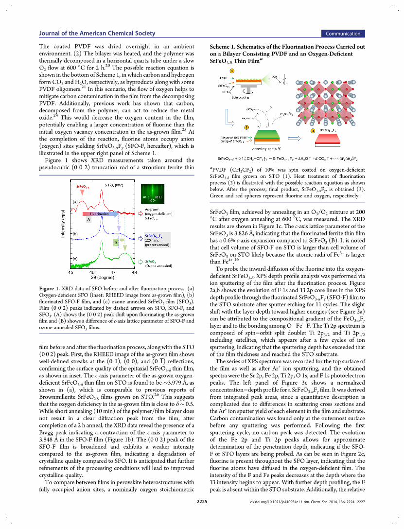
The coated PVDF was dried overnight in an ambientenvironment. (2) The bilayer was heated, and the polymer wasthermally decomposed in a horizontal quartz tube under a slowO2 flow at 600 °C for 2 h.20 The possible reaction equation isshown in the bottom of Scheme 1, in which carbon and hydrogenform CO2 and H2O, respectively, as byproducts along with somePVDF oligomers.21 In this scenario, the flow of oxygen helps tomitigate carbon contamination in the film from the decomposingPVDF. Additionally, previous work has shown that carbon,decomposed from the polymer, can act to reduce the metaloxide.24 This would decrease the oxygen content in the film,potentially enabling a larger concentration of fluorine than theinitial oxygen vacancy concentration in the as-grown film.25 Atthe completion of the reaction, fluorine atoms occupy anion(oxygen) sites yielding SrFeO3‑αFγ (SFO-F, hereafter), which isillustrated in the upper right panel of Scheme 1.Figure 1 shows XRD measurements taken around the
pseudocubic (0 0 2) truncation rod of a strontium ferrite thin
film before and after the fluorination process, along with the STO(0 0 2) peak. First, the RHEED image of the as-grown film showswell-defined streaks at the (0 1), (0 0), and (0 1 ) reflections,confirming the surface quality of the epitaxial SrFeO3‑δ thin film,as shown in inset. The c-axis parameter of the as-grown oxygen-deficient SrFeO3‑δ thin film on STO is found to be ∼3.979 Å, asshown in (a), which is comparable to previous reports ofBrownmillerite SrFeO2.5 films grown on STO.26 This suggeststhat the oxygen deficiency in the as-grown film is close to δ∼ 0.5.While short annealing (10 min) of the polymer/film bilayer doesnot result in a clear diffraction peak from the film, aftercompletion of a 2 h anneal, the XRD data reveal the presence of aBragg peak indicating a contraction of the c-axis parameter to3.848 Å in the SFO-F film (Figure 1b). The (0 0 2) peak of theSFO-F film is broadened and exhibits a weaker intensitycompared to the as-grown film, indicating a degradation ofcrystalline quality compared to SFO. It is anticipated that furtherrefinements of the processing conditions will lead to improvedcrystalline quality.To compare between films in perovskite heterostructures with
fully occupied anion sites, a nominally oxygen stoichiometric
SrFeO3 film, achieved by annealing in an O3/O2 mixture at 200°C after oxygen annealing at 600 °C, was measured. The XRDresults are shown in Figure 1c. The c-axis lattice parameter of theSrFeO3 is 3.826 Å, indicating that the fluorinated ferrite thin filmhas a 0.6% c-axis expansion compared to SrFeO3 (B). It is notedthat cell volume of SFO-F on STO is larger than cell volume ofSrFeO3 on STO likely because the atomic radii of Fe3+ is largerthan Fe4+.16
To probe the inward diffusion of the fluorine into the oxygen-deficient SrFeO3‑δ, XPS depth profile analysis was performed viaion sputtering of the film after the fluorination process. Figure2a,b shows the evolution of F 1s and Ti 2p core lines in the XPSdepth profile through the fluorinated SrFeO3‑αFγ (SFO-F) film tothe STO substrate after sputter etching for 11 cycles. The slightshift with the layer depth toward higher energies (see Figure 2a)can be attributed to the compositional gradient of the FeO3‑αFγlayer and to the bonding amongO−Fe−F. The Ti 2p spectrum iscomposed of spin−orbit split doublet Ti 2p3/2 and Ti 2p1/2including satellites, which appears after a few cycles of ionsputtering, indicating that the sputtering depth has exceeded thatof the film thickness and reached the STO substrate.The series of XPS spectrum was recorded for the top surface of
the film as well as after Ar+ ion sputtering, and the obtainedspectra were the Sr 2p, Fe 2p, Ti 2p, O 1s, and F 1s photoelectronpeaks. The left panel of Figure 3c shows a normalizedconcentration−depth profile for a SrFeO3‑αFγ film. It was derivedfrom integrated peak areas, since a quantitative description iscomplicated due to differences in scattering cross sections andthe Ar+ ion sputter yield of each element in the film and substrate.Carbon contamination was found only at the outermost surfacebefore any sputtering was performed. Following the firstsputtering cycle, no carbon peak was detected. The evolutionof the Fe 2p and Ti 2p peaks allows for approximatedetermination of the penetration depth, indicating if the SFO-F or STO layers are being probed. As can be seen in Figure 2c,fluorine is present throughout the SFO layer, indicating that thefluorine atoms have diffused in the oxygen-deficient film. Theintensity of the F and Fe peaks decreases at the depth where theTi intensity begins to appear. With further depth profiling, the Fpeak is absent within the STO substrate. Additionally, the relative
Figure 1. XRD data of SFO before and after fluorination process. (a)Oxygen-deficient SFO (inset: RHEED image from as-grown film), (b)fluorinated SFO-F film, and (c) ozone annealed SrFeO3 film (SFO3).Film (0 0 2) peaks indicated by dashed arrows on SFO, SFO-F, andSFO3. (A) shows the (0 0 2) peak shift upon fluorinating the as-grownfilm and (B) shows a difference of c-axis lattice parameter of SFO-F andozone-annealed SFO3 films.
Scheme 1. Schematics of the Fluorination Process Carried outon a Bilayer Consisting PVDF and an Oxygen-DeficientSrFeO3‑δ Thin Filma
aPVDF (CH2CF2) of 10% was spin coated on oxygen-deficientSrFeO3‑δ film grown on STO (1). Heat treatment of fluorinationprocess (2) is illustrated with the possible reaction equation as shownbelow. After the process, final product, SrFeO3‑αFγ, is obtained (3).Green and red spheres represent fluorine and oxygen, respectively.
Journal of the American Chemical Society Communication
dx.doi.org/10.1021/ja410954z | J. Am. Chem. Soc. 2014, 136, 2224−22272225
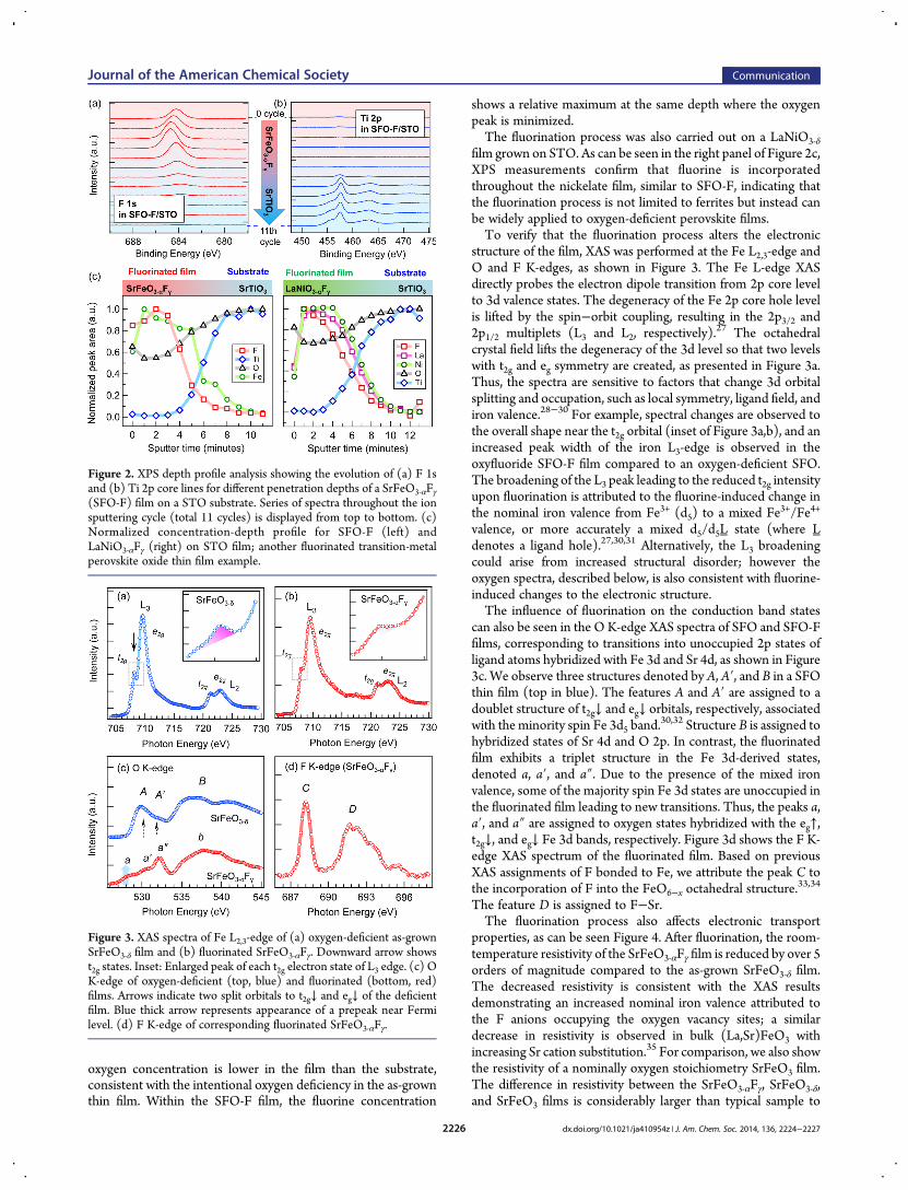
oxygen concentration is lower in the film than the substrate,consistent with the intentional oxygen deficiency in the as-grownthin film. Within the SFO-F film, the fluorine concentration
shows a relative maximum at the same depth where the oxygenpeak is minimized.The fluorination process was also carried out on a LaNiO3‑δ
film grown on STO. As can be seen in the right panel of Figure 2c,XPS measurements confirm that fluorine is incorporatedthroughout the nickelate film, similar to SFO-F, indicating thatthe fluorination process is not limited to ferrites but instead canbe widely applied to oxygen-deficient perovskite films.To verify that the fluorination process alters the electronic
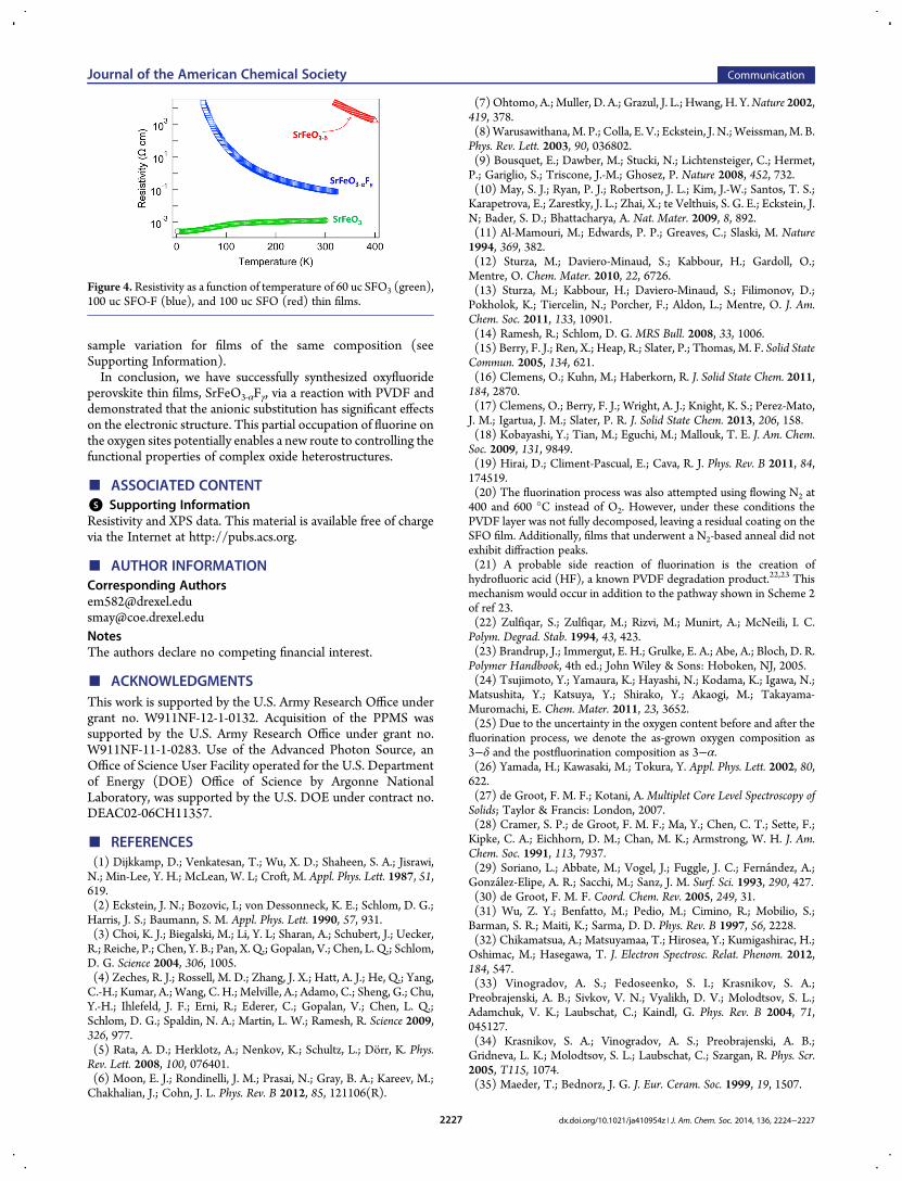
structure of the film, XAS was performed at the Fe L2,3-edge andO and F K-edges, as shown in Figure 3. The Fe L-edge XASdirectly probes the electron dipole transition from 2p core levelto 3d valence states. The degeneracy of the Fe 2p core hole levelis lifted by the spin−orbit coupling, resulting in the 2p3/2 and2p1/2 multiplets (L3 and L2, respectively).
27 The octahedralcrystal field lifts the degeneracy of the 3d level so that two levelswith t2g and eg symmetry are created, as presented in Figure 3a.Thus, the spectra are sensitive to factors that change 3d orbitalsplitting and occupation, such as local symmetry, ligand field, andiron valence.28−30 For example, spectral changes are observed tothe overall shape near the t2g orbital (inset of Figure 3a,b), and anincreased peak width of the iron L3-edge is observed in theoxyfluoride SFO-F film compared to an oxygen-deficient SFO.The broadening of the L3 peak leading to the reduced t2g intensityupon fluorination is attributed to the fluorine-induced change inthe nominal iron valence from Fe3+ (d5) to a mixed Fe3+/Fe4+
valence, or more accurately a mixed d5/d5L state (where Ldenotes a ligand hole).27,30,31 Alternatively, the L3 broadeningcould arise from increased structural disorder; however theoxygen spectra, described below, is also consistent with fluorine-induced changes to the electronic structure.The influence of fluorination on the conduction band states
can also be seen in the O K-edge XAS spectra of SFO and SFO-Ffilms, corresponding to transitions into unoccupied 2p states ofligand atoms hybridized with Fe 3d and Sr 4d, as shown in Figure3c. We observe three structures denoted by A, A′, and B in a SFOthin film (top in blue). The features A and A′ are assigned to adoublet structure of t2g↓ and eg↓ orbitals, respectively, associatedwith the minority spin Fe 3d5 band.
30,32 Structure B is assigned tohybridized states of Sr 4d and O 2p. In contrast, the fluorinatedfilm exhibits a triplet structure in the Fe 3d-derived states,denoted a, a′, and a″. Due to the presence of the mixed ironvalence, some of the majority spin Fe 3d states are unoccupied inthe fluorinated film leading to new transitions. Thus, the peaks a,a′, and a″ are assigned to oxygen states hybridized with the eg↑,t2g↓, and eg↓ Fe 3d bands, respectively. Figure 3d shows the F K-edge XAS spectrum of the fluorinated film. Based on previousXAS assignments of F bonded to Fe, we attribute the peak C tothe incorporation of F into the FeO6−x octahedral structure.
33,34
The feature D is assigned to F−Sr.The fluorination process also affects electronic transport
properties, as can be seen Figure 4. After fluorination, the room-temperature resistivity of the SrFeO3‑αFγ film is reduced by over 5orders of magnitude compared to the as-grown SrFeO3‑δ film.The decreased resistivity is consistent with the XAS resultsdemonstrating an increased nominal iron valence attributed tothe F anions occupying the oxygen vacancy sites; a similardecrease in resistivity is observed in bulk (La,Sr)FeO3 withincreasing Sr cation substitution.35 For comparison, we also showthe resistivity of a nominally oxygen stoichiometry SrFeO3 film.The difference in resistivity between the SrFeO3‑αFγ, SrFeO3‑δ,and SrFeO3 films is considerably larger than typical sample to
Figure 2. XPS depth profile analysis showing the evolution of (a) F 1sand (b) Ti 2p core lines for different penetration depths of a SrFeO3‑αFγ(SFO-F) film on a STO substrate. Series of spectra throughout the ionsputtering cycle (total 11 cycles) is displayed from top to bottom. (c)Normalized concentration-depth profile for SFO-F (left) andLaNiO3‑αFγ (right) on STO film; another fluorinated transition-metalperovskite oxide thin film example.
Figure 3. XAS spectra of Fe L2,3-edge of (a) oxygen-deficient as-grownSrFeO3‑δ film and (b) fluorinated SrFeO3‑αFγ. Downward arrow showst2g states. Inset: Enlarged peak of each t2g electron state of L3 edge. (c) OK-edge of oxygen-deficient (top, blue) and fluorinated (bottom, red)films. Arrows indicate two split orbitals to t2g↓ and eg↓ of the deficientfilm. Blue thick arrow represents appearance of a prepeak near Fermilevel. (d) F K-edge of corresponding fluorinated SrFeO3‑αFγ.
Journal of the American Chemical Society Communication
dx.doi.org/10.1021/ja410954z | J. Am. Chem. Soc. 2014, 136, 2224−22272226
sample variation for films of the same composition (seeSupporting Information).In conclusion, we have successfully synthesized oxyfluoride
perovskite thin films, SrFeO3‑αFγ, via a reaction with PVDF anddemonstrated that the anionic substitution has significant effectson the electronic structure. This partial occupation of fluorine onthe oxygen sites potentially enables a new route to controlling thefunctional properties of complex oxide heterostructures.
■ ASSOCIATED CONTENT*S Supporting InformationResistivity and XPS data. This material is available free of chargevia the Internet at http://pubs.acs.org.
■ AUTHOR INFORMATIONCorresponding [email protected]@coe.drexel.eduNotesThe authors declare no competing financial interest.
■ ACKNOWLEDGMENTSThis work is supported by the U.S. Army Research Office undergrant no. W911NF-12-1-0132. Acquisition of the PPMS wassupported by the U.S. Army Research Office under grant no.W911NF-11-1-0283. Use of the Advanced Photon Source, anOffice of Science User Facility operated for the U.S. Departmentof Energy (DOE) Office of Science by Argonne NationalLaboratory, was supported by the U.S. DOE under contract no.DEAC02-06CH11357.
■ REFERENCES(1) Dijkkamp, D.; Venkatesan, T.; Wu, X. D.; Shaheen, S. A.; Jisrawi,N.; Min-Lee, Y. H.; McLean, W. L; Croft, M. Appl. Phys. Lett. 1987, 51,619.(2) Eckstein, J. N.; Bozovic, I.; von Dessonneck, K. E.; Schlom, D. G.;Harris, J. S.; Baumann, S. M. Appl. Phys. Lett. 1990, 57, 931.(3) Choi, K. J.; Biegalski, M.; Li, Y. L; Sharan, A.; Schubert, J.; Uecker,R.; Reiche, P.; Chen, Y. B.; Pan, X. Q.; Gopalan, V.; Chen, L. Q.; Schlom,D. G. Science 2004, 306, 1005.(4) Zeches, R. J.; Rossell, M. D.; Zhang, J. X.; Hatt, A. J.; He, Q.; Yang,C.-H.; Kumar, A.; Wang, C. H.; Melville, A.; Adamo, C.; Sheng, G.; Chu,Y.-H.; Ihlefeld, J. F.; Erni, R.; Ederer, C.; Gopalan, V.; Chen, L. Q.;Schlom, D. G.; Spaldin, N. A.; Martin, L. W.; Ramesh, R. Science 2009,326, 977.(5) Rata, A. D.; Herklotz, A.; Nenkov, K.; Schultz, L.; Dorr, K. Phys.Rev. Lett. 2008, 100, 076401.(6) Moon, E. J.; Rondinelli, J. M.; Prasai, N.; Gray, B. A.; Kareev, M.;Chakhalian, J.; Cohn, J. L. Phys. Rev. B 2012, 85, 121106(R).
(7) Ohtomo, A.; Muller, D. A.; Grazul, J. L.; Hwang, H. Y.Nature 2002,419, 378.(8)Warusawithana, M. P.; Colla, E. V.; Eckstein, J. N.;Weissman,M. B.Phys. Rev. Lett. 2003, 90, 036802.(9) Bousquet, E.; Dawber, M.; Stucki, N.; Lichtensteiger, C.; Hermet,P.; Gariglio, S.; Triscone, J.-M.; Ghosez, P. Nature 2008, 452, 732.(10) May, S. J.; Ryan, P. J.; Robertson, J. L.; Kim, J.-W.; Santos, T. S.;Karapetrova, E.; Zarestky, J. L.; Zhai, X.; te Velthuis, S. G. E.; Eckstein, J.N; Bader, S. D.; Bhattacharya, A. Nat. Mater. 2009, 8, 892.(11) Al-Mamouri, M.; Edwards, P. P.; Greaves, C.; Slaski, M. Nature1994, 369, 382.(12) Sturza, M.; Daviero-Minaud, S.; Kabbour, H.; Gardoll, O.;Mentre, O. Chem. Mater. 2010, 22, 6726.(13) Sturza, M.; Kabbour, H.; Daviero-Minaud, S.; Filimonov, D.;Pokholok, K.; Tiercelin, N.; Porcher, F.; Aldon, L.; Mentre, O. J. Am.Chem. Soc. 2011, 133, 10901.(14) Ramesh, R.; Schlom, D. G. MRS Bull. 2008, 33, 1006.(15) Berry, F. J.; Ren, X.; Heap, R.; Slater, P.; Thomas, M. F. Solid StateCommun. 2005, 134, 621.(16) Clemens, O.; Kuhn, M.; Haberkorn, R. J. Solid State Chem. 2011,184, 2870.(17) Clemens, O.; Berry, F. J.; Wright, A. J.; Knight, K. S.; Perez-Mato,J. M.; Igartua, J. M.; Slater, P. R. J. Solid State Chem. 2013, 206, 158.(18) Kobayashi, Y.; Tian, M.; Eguchi, M.; Mallouk, T. E. J. Am. Chem.Soc. 2009, 131, 9849.(19) Hirai, D.; Climent-Pascual, E.; Cava, R. J. Phys. Rev. B 2011, 84,174519.(20) The fluorination process was also attempted using flowing N2 at400 and 600 °C instead of O2. However, under these conditions thePVDF layer was not fully decomposed, leaving a residual coating on theSFO film. Additionally, films that underwent a N2-based anneal did notexhibit diffraction peaks.(21) A probable side reaction of fluorination is the creation ofhydrofluoric acid (HF), a known PVDF degradation product.22,23 Thismechanism would occur in addition to the pathway shown in Scheme 2of ref 23.(22) Zulfiqar, S.; Zulfiqar, M.; Rizvi, M.; Munirt, A.; McNeili, I. C.Polym. Degrad. Stab. 1994, 43, 423.(23) Brandrup, J.; Immergut, E. H.; Grulke, E. A.; Abe, A.; Bloch, D. R.Polymer Handbook, 4th ed.; John Wiley & Sons: Hoboken, NJ, 2005.(24) Tsujimoto, Y.; Yamaura, K.; Hayashi, N.; Kodama, K.; Igawa, N.;Matsushita, Y.; Katsuya, Y.; Shirako, Y.; Akaogi, M.; Takayama-Muromachi, E. Chem. Mater. 2011, 23, 3652.(25) Due to the uncertainty in the oxygen content before and after thefluorination process, we denote the as-grown oxygen composition as3−δ and the postfluorination composition as 3−α.(26) Yamada, H.; Kawasaki, M.; Tokura, Y. Appl. Phys. Lett. 2002, 80,622.(27) de Groot, F. M. F.; Kotani, A.Multiplet Core Level Spectroscopy ofSolids; Taylor & Francis: London, 2007.(28) Cramer, S. P.; de Groot, F. M. F.; Ma, Y.; Chen, C. T.; Sette, F.;Kipke, C. A.; Eichhorn, D. M.; Chan, M. K.; Armstrong, W. H. J. Am.Chem. Soc. 1991, 113, 7937.(29) Soriano, L.; Abbate, M.; Vogel, J.; Fuggle, J. C.; Fernandez, A.;Gonzalez-Elipe, A. R.; Sacchi, M.; Sanz, J. M. Surf. Sci. 1993, 290, 427.(30) de Groot, F. M. F. Coord. Chem. Rev. 2005, 249, 31.(31) Wu, Z. Y.; Benfatto, M.; Pedio, M.; Cimino, R.; Mobilio, S.;Barman, S. R.; Maiti, K.; Sarma, D. D. Phys. Rev. B 1997, 56, 2228.(32) Chikamatsua, A.; Matsuyamaa, T.; Hirosea, Y.; Kumigashirac, H.;Oshimac, M.; Hasegawa, T. J. Electron Spectrosc. Relat. Phenom. 2012,184, 547.(33) Vinogradov, A. S.; Fedoseenko, S. I.; Krasnikov, S. A.;Preobrajenski, A. B.; Sivkov, V. N.; Vyalikh, D. V.; Molodtsov, S. L.;Adamchuk, V. K.; Laubschat, C.; Kaindl, G. Phys. Rev. B 2004, 71,045127.(34) Krasnikov, S. A.; Vinogradov, A. S.; Preobrajenski, A. B.;Gridneva, L. K.; Molodtsov, S. L.; Laubschat, C.; Szargan, R. Phys. Scr.2005, T115, 1074.(35) Maeder, T.; Bednorz, J. G. J. Eur. Ceram. Soc. 1999, 19, 1507.
Figure 4. Resistivity as a function of temperature of 60 uc SFO3 (green),100 uc SFO-F (blue), and 100 uc SFO (red) thin films.
Journal of the American Chemical Society Communication
dx.doi.org/10.1021/ja410954z | J. Am. Chem. Soc. 2014, 136, 2224−22272227