Molten Metal Temperature Indicator by Libratherm Instruments Private Limited Mumbai

Fluidity of molten metal
A term commonly used to describe the capability of the molten metal to fill mold cavities is fluidity.
This term consists of two basic factors: (1) characteristic molten metal and (2) casting parameters.
The following characteristics of molten metal influence fluidity.
a) Viscosity. As viscosity and its sensitivity to temperature (viscosity index) increase, fluidity
decreases.
b) Surface tension. A high surface tension of the liquid metal reduces fluidity. Oxide films
developed on the surface of the molten metal thus have a significant effect on fluidity. For example,
the oxide film on the surface of pure molten aluminum triples the surface tension.
c) Inclusions. As insoluble particles, inclusions can have a significant adverse effect on fluidity.
This effect can be verified by observing the viscosity of a liquid such as oil with and without sand
particles in it; the former has higher viscosity.
d) Solidification pattern of the alloy. Fluidity is inversely proportional to the freezing range. Thus
the shorter the range (as in pure metals and eutectics), the higher the fluidity becomes. Conversely,
alloys with long freezing ranges (such as solid-solution alloys) have lower fluidity.
Tests for fluidity. Although none is accepted universally, several tests have been developed to
quantify fluidity. One such test is shown in Fig., where the molten metal is made to flow along a
channel at room temperature. The distance of metal flow before it solidifies and stops is a measure
of its fluidity. Obviously this length is a function of the thermal properties of the metal and the
mold, as well as the design of the channel. Such tests are useful and simulate casting situations to a
reasonable degree.
A test method for fluidity using a spiral mold. The fluidity index is the length of the solidified metal in the spiral
passage. The greater the length of the solidified metal, the greater is its fluidity.
Heat transfer
An important consideration in casting is the heat transfer during the complete cycle from pouring
to solidification and cooling to room temperature. Heat flow at different locations in the system
is a complex phenomenon; it depends on many factors relating to the casting material and the mold
and process parameters. For instance, in casting thin sections the metal flow rates must be high
enough to avoid premature chilling and solidification. But, the flow rate must not be so fast as to
cause excessive turbulence, which its detrimental effects on the casting process.
Solidification time
During the early stages of solidification, a thin solidified skin begins to form at the cool mold walls
and, as times passes, the skin thickens. With flat mold walls, this thickness is proportional to the
square root of time. Thus doubling the time will make the skin √2 = 1.41 times, or 41 percent,
thicker. The solidification time is a function of the volume of a casting and its surface area
(Chvorinov's rule):
Solidification time = C (volume/surface area)2 (1)
Where C is a constant that reflects mold material, metal properties (including latent heat), and
temperature. Thus a large sphere solidifies and cools to ambient temperature at a much slower rate
than does a smaller sphere. The reason is that the volume of a sphere is proportional to the cube of
its diameter, and the surface area is proportional to the square of its diameter. Similarly, we can
show that molten metal in a cube-shaped mold will solidify faster than in a spherical mold of the
same volume.
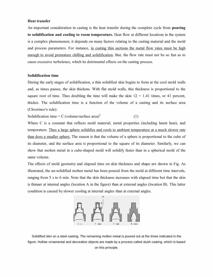
The effects of mold geometry and elapsed time on skin thickness and shape are shown in Fig. As
illustrated, the un-solidified molten metal has been poured from the mold at different time intervals,
ranging from 5 s to 6 min. Note that the skin thickness increases with elapsed time but that the skin
is thinner at internal angles (location A in the figure) than at external angles (location B). This latter
condition is caused by slower cooling at internal angles than at external angles.
Solidified skin on a steel casting. The remaining molten metal is poured out at the times indicated in the
figure. Hollow ornamental and decorative objects are made by a process called slush casting, which is based
on this principle.

Example: Solidification times for various shapes
Three pieces being cast have the same volume but different shapes. One is a sphere, one a cube, and
the other a cylinder with a height equal to its diameter. Which piece will solidify the fastest and
which one the slowest?
SOLUTION: The volume is unity, so we have from Eq. (1): Solidification time α 1/ (surface area)2 The respective surface areas are Sphere: V = (4/3) πr3, r = (3/4π)1/3, and A = 4πr2 = 4π (3/4π)2/3 = 4.84; Cube: V = a3, a = 1, and A = 6a2 = 6; Cylinder: V = πr2h = 2 πr3, r = (1/2π)1/3 and A = 2πr2 + 2πrh = 6πr2 = 6 π (1/2π)2/3 = 5.54. Thus the respective solidification times t are tsphere = 0.043 C, tcube= 0.028 C, and tcylinder = 0.033 C. Hence the cube-shaped casting will solidify the fastest and the sphere-shaped casting will solidify the slowest.
Shrinkage
Because of their thermal expansion characteristics, metals shrink (contract) d solidification and
cooling. Shrinkage, which causes dimensional changes-and, sometimes, cracking-is the result of:
a) Contraction of the molten metal as it cools prior to its solidification.
b) Contraction of the metal during phase change from liquid to solid (latent heat of fusion).
c) Contraction of the solidified metal (the casting) as its temperature drops to ambient temperature.
This chapter [11] is organized around the major classifications of casting practices. These
classifications are related to mold materials, molding processes, and methods of feeding the mold
with the molten metal. The two major categories are expendable-mold and permanent-mold casting.
Expendable molds are made of sand, plaster, ceramics, and similar materials, which are generally
mixed with various binders, or bonding agents. These materials are refractories, that is, they have
the capability to withstand the high temperatures of molten metals. After the casting has solidified,
the molds in these processes are broken up to remove the casting.
Permanent molds, as the names imply, are used repeatedly and are designed in such a way that the
casting can be easily removed and the mold used for the next casting. These molds are made of
metals that maintain their strength at high temperatures and thus can be used repeatedly. Because
metal molds are better heat conductors than expendable molds, the solidifying casting is subjected
to a higher rate of cooling, which in turn affects the microstructure and grain size within the casting.
Composite molds are made of two or more different materials, such as sand, graphite, and metal,
combining the advantages of each material. They are used in various casting processes to improve
mold strength, cooling rates, and overall economics of the process.
Shell-Mold Casting
In this process, a mounted pattern made of a ferrous metal or aluminum is heated to 175-370 °C,
coated with a parting agent such as silicone, and clamped to a box or chamber containing a fine
sand containing 2.5 to 4.0 percent thermosetting resin binder such as phenol-formaldehyde, which
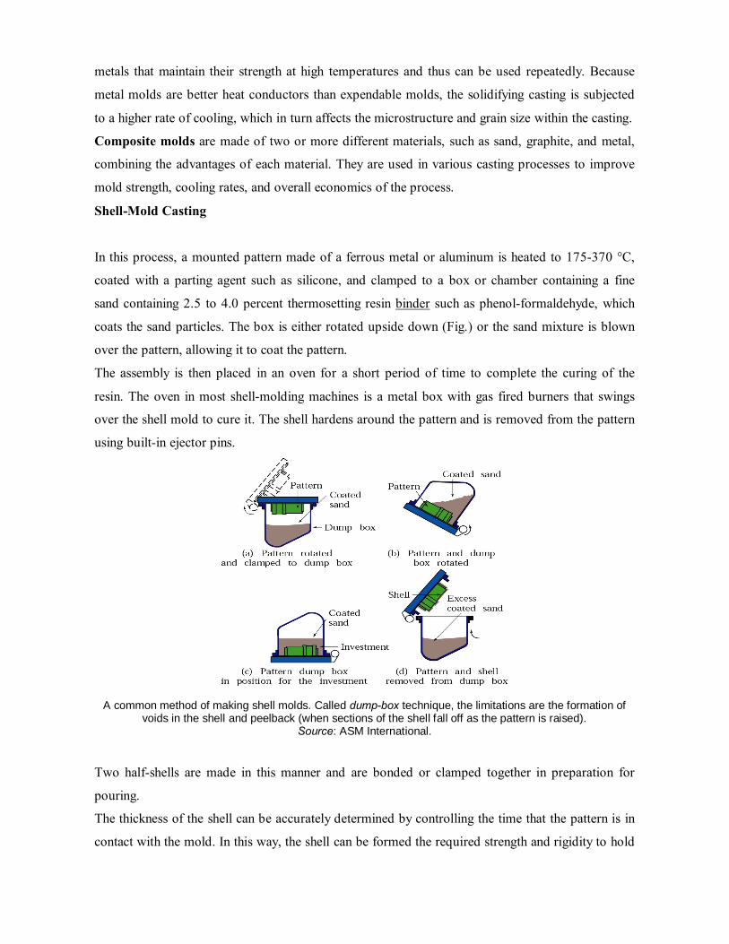
coats the sand particles. The box is either rotated upside down (Fig.) or the sand mixture is blown
over the pattern, allowing it to coat the pattern.
The assembly is then placed in an oven for a short period of time to complete the curing of the
resin. The oven in most shell-molding machines is a metal box with gas fired burners that swings
over the shell mold to cure it. The shell hardens around the pattern and is removed from the pattern
using built-in ejector pins.
A common method of making shell molds. Called dump-box technique, the limitations are the formation of voids in the shell and peelback (when sections of the shell fall off as the pattern is raised).
Source: ASM International. Two half-shells are made in this manner and are bonded or clamped together in preparation for
pouring.
The thickness of the shell can be accurately determined by controlling the time that the pattern is in
contact with the mold. In this way, the shell can be formed the required strength and rigidity to hold

the weight of the molten liquid. The shells are light and thin, usually 5-10 mm, and consequently
their thermal characteristics are different from those for thicker molds.
The high quality of the finished casting can significantly reduce cleaning, machining, and other
finishing costs. Complex shapes can be produced with less labor, and the process can be automated
fairly easily. Shell-molding applications include small mechanical parts requiring high precision,
such as gear housing, cylinder heads, and connecting rods. Shell molding is also widely used in
producing high precision molding cores.
Expandable Pattern Casting (Lost Foam)
The expandable pattern casting process uses a polystyrene pattern, which evaporates upon contact
with molten metal to form a cavity for the casting. The process is also known as evaporative-pattern
or lost-pattern casting, and has become one of the more important casting processes for ferrous and
nonferrous metals, particularly for the automotive industry.
First, raw expandable polystyrene (EPS) beads, are placed in a preheated die, usually made of
aluminum. The polystyrene expands and takes the shape of the die cavity. Additional heat is applied
to fuse and bond the beads together. The die is then cooled and opened, and the polystyrene pattern
is removed. Complex patterns may also be made by bonding various individual pattern sections
using hot-melt adhesive.
Schematic illustration of the expendable pattern casting process, also known as lost foam or evaporative casting.
The pattern is then coated with a water-base refractory slurry, dried, and placed in a flask. The flask
is filled with loose fine sand, which surrounds and supports the pattern. The sand may be dried or
mixed with bonding agents to give it additional strength. Then, without removing the polystyrene
pattern, the molten metal is poured into the mold. This action immediately vaporizes the pattern and
fills the mold cavity, completely replacing the space previously occupied by the polystyrene pattern.
The heat degrades the polystyrene and the degradation products are vented into the surrounding
sand.
The evaporative-pattern process has a number of advantages over other casting methods:
a) It is a relatively simple process because there are no parting lines, cores, or riser systems; hence it
has design flexibility.
b) Inexpensive flasks are sufficient for the process.
c) Polystyrene is inexpensive and can be easily processed into patterns having very complex shapes,
various sizes, and fine surface detail.
d) The casting requires minimum finishing and cleaning operations.
e) The process is economical for long production runs. A major factor is the cost to produce the die
for expanding the polystyrene beads to make the pattern.
f) The process can be automated.
Typical applications for this process are cylinder heads, crankshafts, brake components and
manifolds for automobiles, and machine bases. The aluminum engine blocks and other components
of the General Motors Saturn automobile are made by this process.
Ceramic-Mold Casting
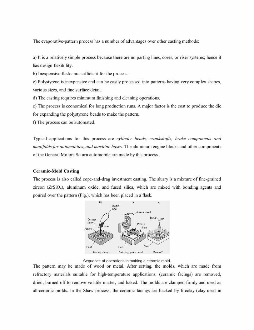
The process is also called cope-and-drag investment casting. The slurry is a mixture of fine-grained
zircon (ZrSiO4), aluminum oxide, and fused silica, which are mixed with bonding agents and
poured over the pattern (Fig.), which has been placed in a flask.
Sequence of operations in making a ceramic mold.
The pattern may be made of wood or metal. After setting, the molds, which are made from
refractory materials suitable for high-temperature applications; (ceramic facings) are removed,
dried, burned off to remove volatile matter, and baked. The molds are clamped firmly and used as
all-ceramic molds. In the Shaw process, the ceramic facings are backed by fireclay (clay used in
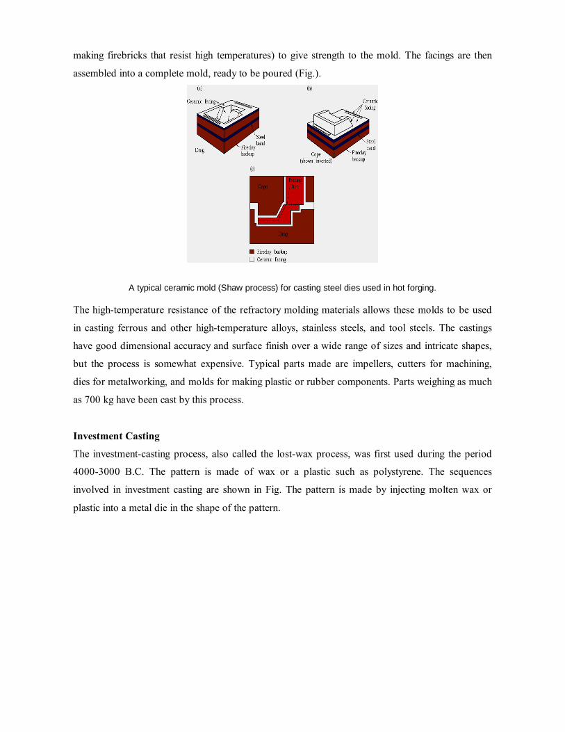
making firebricks that resist high temperatures) to give strength to the mold. The facings are then
assembled into a complete mold, ready to be poured (Fig.).
A typical ceramic mold (Shaw process) for casting steel dies used in hot forging. The high-temperature resistance of the refractory molding materials allows these molds to be used
in casting ferrous and other high-temperature alloys, stainless steels, and tool steels. The castings
have good dimensional accuracy and surface finish over a wide range of sizes and intricate shapes,
but the process is somewhat expensive. Typical parts made are impellers, cutters for machining,
dies for metalworking, and molds for making plastic or rubber components. Parts weighing as much
as 700 kg have been cast by this process.
Investment Casting
The investment-casting process, also called the lost-wax process, was first used during the period
4000-3000 B.C. The pattern is made of wax or a plastic such as polystyrene. The sequences
involved in investment casting are shown in Fig. The pattern is made by injecting molten wax or
plastic into a metal die in the shape of the pattern.

Schematic illustration of investment casting, (lost wax process). Castings by this method can be made with very fine detail and from a variety of metals. Source: Steel Founders' Society of America.
The pattern is then dipped into a slurry of refractory material, such as very fine silica and binders,
including water, ethyl silicate, and acids. After this initial Coating has dried, the pattern is coated
repeatedly to increase its thickness. The term investment comes from the fact that the pattern is
invested with the refractory material. Wax patterns require careful handling because they are not
strong enough to withstand the forces involved during mold making. However, unlike plastic
patterns, wax can be reused. The one-piece mold is dried in air and heated to a temperature of 90-
175 °C in an inverted position to melt out the wax for about 12 hours. The mold is then fired to 650-
1050 °C for about 4 hours, depending on the metal to be cast, to drive off the water of
crystallization. After the mold has been poured and the metal has solidified, the mold is broken up
and the casting is removed. A number of patterns can be joined to make one mold, called a tree
(Fig.c), thus increasing the production rate.
Although the labor and materials involved make the lost-wax process costly, it is suitable for
casting high-melting-point alloys with good surface finish and close tolerances. Thus little or no
finishing operations are required, which would otherwise add significantly to the total cost of the
casting. This process is capable of producing intricate shapes, with parts weighing from 1 g to 35
kg, from a wide variety of ferrous and nonferrous metals and alloys. Typical parts made are
components for office equipment and mechanical components such as gears, cams, valves, and
ratchets.

Ceramic-shell investment casting A variation of the investment-casting process is ceramic-shell
casting. It uses the same type of wax or plastic pattern, which is dipped first in ethyl silicate gel and
then into a fluidized bed of fine-grained fused silica or zircon flour. The pattern is then dipped into
coarser-grained silica to build up additional coatings and thickness to withstand the thermal shock
of pouring. The rest of the procedure is similar to investment casting. This process is economical
and is used extensively for precision casting of steels and high-temperature alloys.
The sequence of operations involved in making a turbine disk by this method is shown in Fig.
Investment casting of an integrally cast rotor for a gas turbine. (a) Wax pattern assembly. (b) Ceramic shell around wax
pattern. (c) Wax is melted out and the mold is filled, under a vacuum, with molten superalloy. (d) The cast rotor, produced to net or near-net shape.
Example: Investment-cast superalloy components for gas turbines Since the 1960s, investment-cast superalloys have been replacing wrought counterparts in high-
performance gas turbines. Much development has been taking place in producing cleaner
superalloys (nickel-base and cobalt-base). Improvements have been made in melting and casting
techniques, such as by vacuum-induction melting, using microprocessor controls. Impurity and
inclusion levels have continually been reduced, thus improving the strength and ductility of these
components. Such control is essential because these parts operate at a temperature only about 50°C
below the solidus.
The microstructure of an investment-cast, gas-turbine rotor is shown in the upper portion of Fig..
Note the fine, uniform, equiaxed grain size throughout the cross section. Recent techniques to
obtain this result include the use of a nucleant addition to the molten metal, as well as close control
of its superheat, pouring techniques, and control of cooling rate of the casting. In contrast, the lower
portion of Fig. shows the same type of rotor cast conventionally; note the coarse grain structure.
This rotor will have inferior properties compared to the fine-grained-rotor. Due to developments in
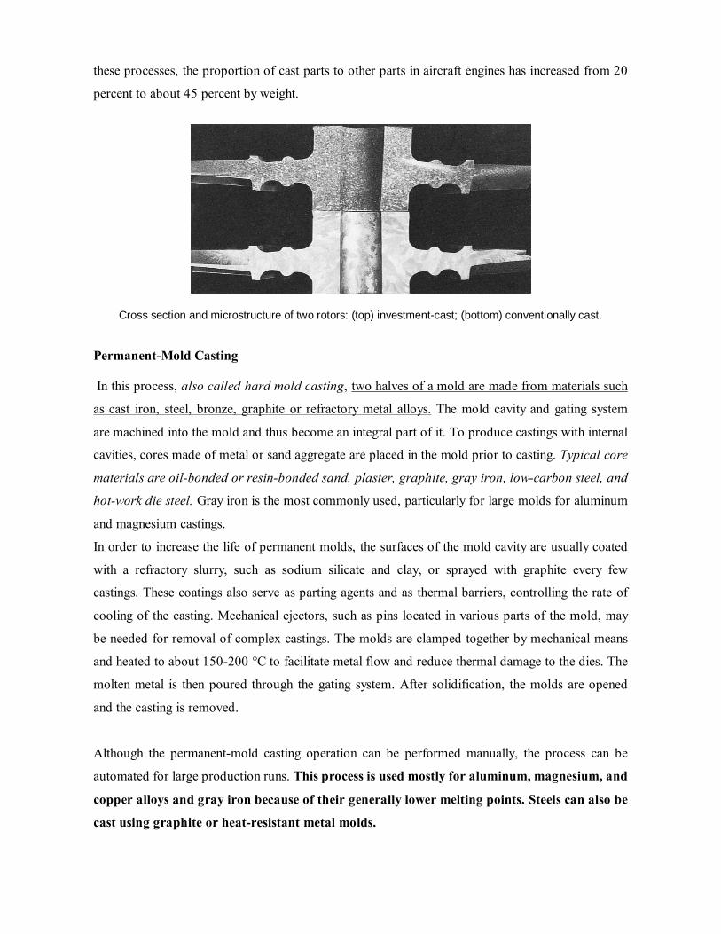
these processes, the proportion of cast parts to other parts in aircraft engines has increased from 20
percent to about 45 percent by weight.
Cross section and microstructure of two rotors: (top) investment-cast; (bottom) conventionally cast.
Permanent-Mold Casting In this process, also called hard mold casting, two halves of a mold are made from materials such
as cast iron, steel, bronze, graphite or refractory metal alloys. The mold cavity and gating system
are machined into the mold and thus become an integral part of it. To produce castings with internal
cavities, cores made of metal or sand aggregate are placed in the mold prior to casting. Typical core
materials are oil-bonded or resin-bonded sand, plaster, graphite, gray iron, low-carbon steel, and
hot-work die steel. Gray iron is the most commonly used, particularly for large molds for aluminum
and magnesium castings.
In order to increase the life of permanent molds, the surfaces of the mold cavity are usually coated
with a refractory slurry, such as sodium silicate and clay, or sprayed with graphite every few
castings. These coatings also serve as parting agents and as thermal barriers, controlling the rate of
cooling of the casting. Mechanical ejectors, such as pins located in various parts of the mold, may
be needed for removal of complex castings. The molds are clamped together by mechanical means
and heated to about 150-200 °C to facilitate metal flow and reduce thermal damage to the dies. The
molten metal is then poured through the gating system. After solidification, the molds are opened
and the casting is removed.
Although the permanent-mold casting operation can be performed manually, the process can be
automated for large production runs. This process is used mostly for aluminum, magnesium, and
copper alloys and gray iron because of their generally lower melting points. Steels can also be
cast using graphite or heat-resistant metal molds.

This process produces castings with good surface finish, close tolerances, uniform and good
mechanical properties, and at high production rates. Typical parts made by permanent-mold
casting are automobile pistons, cylinder heads, connecting rods, gear blanks for appliances, and
kitchenware. Parts that can be made economically generally weigh less than 25 kg, although special
castings weighing a few hundred kilograms have been made by this process.
Although equipment costs can be high because of die costs, the process can be mechanized, thus
keeping labor costs low. Permanent-mold casting is not economical for small production runs.
Furthermore, because of the difficulty in removing the casting from the mold, intricate shapes
cannot be cast by this process.
Slush Casting
We noted earlier [solidification time] that a solidified skin first develops in a casting and that this
skin becomes thicker with time. Hollow castings with thin walls can be made by permanent-mold
casting using this principle. This process is called slush casting. The molten metal is poured into the
metal mold, and after the desired thickness of solidified skin is obtained, the mold is inverted, and
the remaining liquid metal is poured out. The mold halves are then opened and the casting is
removed. The process is suitable for small production runs and is generally used for making
ornamental and decorative objects (such as lamp bases and stems) and toys from low-melting-point
metals, such as zinc, tin, and lead alloys.
Pressure Casting
In the two permanent-mold processes that have just been described, the molten met flows into the
mold cavity by gravity. In the pressure-casting process, also called pressure pouring or low-pressure
casting (Fig. a), the molten metal is forced upward by gas pressure into a graphite or metal mold.
The pressure is maintained until the metal has completely solidified in the mold. The molten metal
may also be forced upward by a vacuum, which also removes dissolved gases and gives the casting
lower porosity.
Pressure casting is generally used for high-quality castings. An example of this process is steel
railroad-car wheels. These wheels may also be cast in sand molds semipermanent molds made of
graphite and sand (Fig. b).

FIGURE: (a) The bottom-pressure casting process utilizes graphite molds for the production of steel railroad wheels. (b) Gravity-pouring method of casting a railroad wheel. Note that the pouring basin also serves as a
riser. Railroad wheels can also be manufactured by forging. Die Casting
The die-casting process, developed in the early 1900s, is a further example of permanent-mold
casting. The molten metal is forced into the die cavity at pressures ranging from 0.7 -700 MPa.
Typical parts made by die casting are carburetors, motors and appliance components, hand tools,
and toys. The weight of most castings ranges from less than 90 g to about 25 kg. There are two
basic types of die-casting machines: hot-chamber and cold-chamber.
Hot-chamber process
The hot-chamber process (Fig.) involves the use of a piston, which traps a certain volume of molten
metal and forces it into the die cavity through a gooseneck and nozzle. The pressures range up to 35
MPa, with an average of about 15 MPa. The metal is held under pressure until it solidifies in the
die. To improve die life and to aid in rapid metal cooling-thus reducing cycle time-dies are usually
cooled by circulating water or oil through various passageways in the die block. Cycle times usually
range up to 900 shots (individual injections) per hour for zinc, although very small components
such as zipper teeth can be cast at 18,000 shots per hour. Low-melting-point alloys such as zinc, tin,
and lead are commonly cast by this process.

FIGURE: Sequence of steps in die casting of a part in the hot-chamber process. Source: Courtesy of Foundry Management and Technology.
Cold-chamber process
In the cold-chamber process (Fig.), molten metal is poured into the injection cylinder (shot
chamber) with a ladle. The shot chamber is not heated-hence the t cold chamber. The metal is
forced into the die cavity at pressures usually ranging f 20 MPa to 70 MPa, although they may be as
high as 150 MPa.
FIGURE: Sequence of operations in die casting of a part in the cold-chamber process. Source: Courtesy of Foundry Management and Technology.
The machines may be horizontal (Fig.) or vertical, in which the shot chamber vertical and the
machine is similar to a vertical press.

FIGURE: Schematic illustration of a die-casting machine. These machines are large compared to the size of
the casting because large forces are required to keep the two halves of the dies closed. Otherwise, the pressure of the molten metal in the die cavities may force the dies apart.
Centrifugal Casting As its name implies, the centrifugal-casting process utilizes the inertial forces ca by rotation to
distribute the molten metal into the mold cavities. In centrifugal casting, hollow cylindrical parts
such as pipes, gun barrels, and streetlamp posts, are produced by the technique shown in Fig., in
which molten metal is poured into a rotating mold. The axis of rotation is usually horizontal but can
be vertical for short work pieces. Molds are made of steel, iron, or graphite and may be coated with
a refractory lining to increase mold life. The mold surfaces can be shaped so that pipes with various
outer shapes, including square or polygonal, can be cast.
FIGURE: Schematic illustration of the centrifugal casting process. Pipes, cylinder liners, and similarly shaped
parts can be cast by this process.

The inner surface of the casting remains cylindrical because the molten metal is uniformly
distributed by centrifugal forces. However, because of density differences, lighter elements such as
impurities and pieces of the refractory lining tend to collect on the inner surface of the casting.
Cylindrical parts ranging from 13 mm to 3 m in diameter and 16 m long can be cast centrifugally,
with wall thicknesses ranging from 6 mm to 125 mm. The pressure generated by the centrifugal
force is high and that pressure is necessary for casting thick-walled parts. Castings of good quality,
dimensional accuracy, and external surface detail are obtained by this process. In addition to pipes,
typical parts made are bushings, engine-cylinder liners, and bearing rings with or without flanges.
Casting Techniques for Single-Crystal Components
Conventional casting of turbine blades
The conventional casting process uses a ceramic mold. The molten metal is poured into the mold
and begins to solidify at the ceramic walls. The grain structure developed is polycrystalline and is
similar to that obtained using nucleating agents. The presence of grain boundaries makes this
structure susceptible to creep and cracking along those boundaries under the centrifugal forces and
elevated temperatures common in an operating gas turbine.
Directionally solidified blades In the directional solidification process (Fig. a), the ceramic mold is
preheated by radiant heating. The mold is supported by a water-cooled chill plate. After the metal is
poured into the mold, the assembly is lowered slowly. Crystals begin to grow at the chill-plate
surface and upward, like the columnar grains shown earlier. The blade is thus directionally
solidified, with longitudinal but no transverse grain boundaries. Consequently the blade is stronger
in the direction of centrifugal forces developed in the gas turbine.
Single-crystal blades
In crystal growing, the mold has constriction in the shape of a corkscrew or helix (Figs. b and c), the
cross-section of which allows only one crystal to fit through. The mechanism of crystal growth such
that only the most favorably oriented crystals are able to grow through the helix because all others
are intercepted by the walls of the helical passage. As the assembly is lowered slowly, a single
crystal grows upward through the constriction and begins to grow in the mold. Strict control of the
rate of movement is necessary. The solidified mass in the mold is single-crystal blade. Although
more expensive than other blades, the lack of grain boundaries makes these blades resistant to creep

and thermal shock. Thus they hay longer and more reliable service life.
Methods of casting turbine blades: (a) directional solidification; (b) method to produce a single-crystal blade; and
(c) a single-crystal blade with the constriction portion still attached. Melting Practice and Furnaces Melting practice is an important aspect of casting operations, because it has a direct bearing on the
quality of castings. Furnaces are charged with melting stock consisting of metal, alloying elements,
and various other materials such as flux and slag-forming constituents. Fluxes are inorganic
compounds that refine the molten metal by removing dissolved gases and various impurities. Fluxes
have several functions, depending on the metal. For example, for aluminum alloys there are cover
fluxes (to form a barrier to oxidation), cleaning fluxes, refining fluxes, and wall-cleaning fluxes
(because of the detrimental effect that some fluxes have on furnace linings, particularly induction
furnaces). Fluxes may be added manually or can be injected automatically into the molten metal.

To protect the surface of the molten metal against atmospheric reaction and contamination-and to
refine the melt-the pour must be insulated against heat loss. Insulation is usually provided by
covering the surface or mixing the melt with compounds that form a slag. In casting steels, the
composition of the slag includes CaO, Si02, MnO, and FeO. A small quantity of liquid metal is
usually tapped and its composition analyzed. Necessary additions or inoculations are then made
prior to pouring the metal into the molds.
The metal charge may be composed of commercially pure primary metals, which are remelted
scrap. Clean scrapped castings, gates, and risers may also be included in the charge. If the melting
points of the alloying elements are sufficiently low, pure alloying elements are added to obtain the
desired composition in the melt.
Melting Furnaces
The melting furnaces commonly used in foundries are: Electric-arc, induction, crucible, and
cupolas.
Electric-arc furnaces are used extensively in foundries and have advantages such as high rate of
melting (thus high production rate), much less pollution than other types of furnaces and the ability
to hold the molten metal for any length of time for alloying purposes.
Induction furnaces are especially useful in smaller foundries a produce composition-controlled
smaller melts. The coreless induction furnace consists of a crucible completely surrounded with a
water-cooled copper coil through which high frequency current passes. Because there is a strong
electromagnetic stirring action during induction heating, this type of furnace has excellent mixing
characteristics for alloying and adding new charge of metal.
Crucible furnaces (Fig. a), which have been used extensively throughout history, are heated with
various fuels, such as commercial gases, fuel oil, fossil fuel as well as electricity. They may be
stationary, tilting, or movable. Many ferrous and nonferrous metals are melted in these furnaces.
Cupolas are basically refractory-lined vertical steel vessels that are charged with alternating layers
of metal, coke, and flux (Fig. b). Although they require major investments and are being replaced
by induction furnaces, cupolas operate continuously, have high melting rates, and produce large
amounts of molten metal.

Furnace selection requires careful consideration of several factors that can significantly influence
the quality of castings, as well as the economics of casting operations. A variety of furnaces meet
requirements for melting and casting metals and alloys in foundries, so proper selection of a furnace
generally depends on:
a) Economic considerations, such as initial cost and operating and maintenance costs.
b) The composition and melting point of the alloy to be cast and ease of controlling metal
chemistry.
c) Control of the furnace atmosphere to avoid contamination of the metal.
d) Capacity and the rate of melting required.
e) Environmental considerations, such as air pollution and noise.
f) Power supply and its availability and cost of fuels.
g) Ease of superheating the metal.
h) Type of charge material that can be used.