Fluid Properties Lab
25
Fluid Mechanics Lab, Experiment #1 EXPERIMENT #1 Properties of Fluids Background: The term "fluid" relates to both gases and liquids (e.g. air and water) and, although there are differences between them, they both have the same essential property that when acted upon by any unbalanced external force an infinite change of shape will occur if the force acts for a long enough time. Alternatively, one may say that if acted on by a force, a fluid will move continuously while a solid will distort only a fixed amount. If a shear force is applied to one surface of a volume of fluid, the layers of fluid will move over one another thus producing a velocity gradient in the fluid. For a given shear stress, a property called the viscosity determines the velocity gradient and hence the velocity of the fluid in the plane of the applied stress. The viscosity is a measure of the fluid's resistance to motion. Viscosity if a very important property in fluid mechanics since it determines the behavior of fluids whenever they move relative to solid surfaces. Liquids and gases both share the property of "fluidity" described above, but they differ in other respects. A quantity of liquid has a definite volume and if in contact with a gas it has a definite boundary or "free surface." Gases, on the other hand, expand to fill the space available and cannot be considered as having a definite volume unless constrained on all sides by fixed boundaries (e.g. a totally enclosed vessel). The volume of a liquid changes slightly with pressure and temperature, but for a gas these changes can be very large. For most engineering purposes liquids can be regarded as incompressible, meaning volume and density do not change significantly with pressure, whereas gases usually have to be treated as compressible. Similarly, the effects of varying temperature can often be ignored for liquids (except in certain special cases), but must be taken into account with gases. The engineer is often concerned with determining the forces produced by static or moving fluids and when doing this the above differences between liquids and gases can be very important. Generally it is much easier to deal with liquids because, for most purposes, it can be assumed that their volume and density do not change with pressure and temperature. In the study of hydrostatics we are primarily concerned with the forces due to static liquids. The forces result from the pressure acting in the liquid and at a given point this depends on the Department of Mechanical and Aerospace Engineering Florida Institute of Technology 1
description
Fluid Mechanics: Fluid Properties Lab. Find the density, specific gravity and viscosity using a hydrometer, falling ball viscometer, and a rotating cylinder pulley viscometer.
Transcript of Fluid Properties Lab

Fluid Mechanics Lab, Experiment #1
EXPERIMENT #1Properties of Fluids
Background: The term "fluid" relates to both gases and liquids (e.g. air and water) and, although there are differences between them, they both have the same essential property that when acted upon by any unbalanced external force an infinite change of shape will occur if the force acts for a long enough time. Alternatively, one may say that if acted on by a force, a fluid will move continuously while a solid will distort only a fixed amount. If a shear force is applied to one surface of a volume of fluid, the layers of fluid will move over one another thus producing a velocity gradient in the fluid. For a given shear stress, a property called the viscosity determines the velocity gradient and hence the velocity of the fluid in the plane of the applied stress. The viscosity is a measure of the fluid's resistance to motion. Viscosity if a very important property in fluid mechanics since it determines the behavior of fluids whenever they move relative to solid surfaces.
Liquids and gases both share the property of "fluidity" described above, but they differ in other respects. A quantity of liquid has a definite volume and if in contact with a gas it has a definite boundary or "free surface." Gases, on the other hand, expand to fill the space available and cannot be considered as having a definite volume unless constrained on all sides by fixed boundaries (e.g. a totally enclosed vessel). The volume of a liquid changes slightly with pressure and temperature, but for a gas these changes can be very large. For most engineering purposes liquids can be regarded as incompressible, meaning volume and density do not change significantly with pressure, whereas gases usually have to be treated as compressible. Similarly, the effects of varying temperature can often be ignored for liquids (except in certain special cases), but must be taken into account with gases.
The engineer is often concerned with determining the forces produced by static or moving fluids and when doing this the above differences between liquids and gases can be very important. Generally it is much easier to deal with liquids because, for most purposes, it can be assumed that their volume and density do not change with pressure and temperature. In the study of hydrostatics we are primarily concerned with the forces due to static liquids. The forces result from the pressure acting in the liquid and at a given point this depends on the depth below the free surface. Density, or mass per unit volume, is a basic property which must be known before any calculations of forces can be made.
When considering the interfaces between liquids, solids, and gases, there is a further property which can produce forces and this is called the surface tension. When a liquid/gas interface is in contact with a solid boundary, the edge of the liquid will be distorted upward or downward depending on whether the solid attracts or repels the liquid. If the liquid is attracted to, or "wets" the solid, it will move upward at the edge and the surface tension will cause a small upward force on the body of the liquid. If the liquid is in a tube the force will act all around the periphery and the liquid may be drawn up the tube by a small amount. This is sometimes called the capillarity effect or capilliary action. The forces involved are small and the effect need only be considered in a limited number of special cases.
PART I - DENSITY
Statement of Work: To determine the density of a liquid it is necessary to measure the mass of a known volume of liquid.
(1)
The density of pure water at 20oC is 998.2 kg/m3 and this is sometimes rounded up to 1000 kg/m3
for engineering purposes. The experimental result should be within 1% of this value. The measurement of volume is not very precise and depends on the accuracy of the graduations on the beaker and this cannot be checked.
Department of Mechanical and Aerospace Engineering Florida Institute of Technology
1

Fluid Mechanics Lab, Experiment #1
Density Bottle: The problem of accurately measuring a volume of liquid can be overcome by using a special vessel with a known volume such as a density bottle. This is accurately made and has a glass stopper with a hole in it through which excess liquid is expelled. When the liquid is level with the top of the stopper, the volume of liquid is 50 cm3 (ml).
Procedure for determination of density
Dry and weigh the bottle and stopper.
Fill the bottle with liquid and replace the stopper.
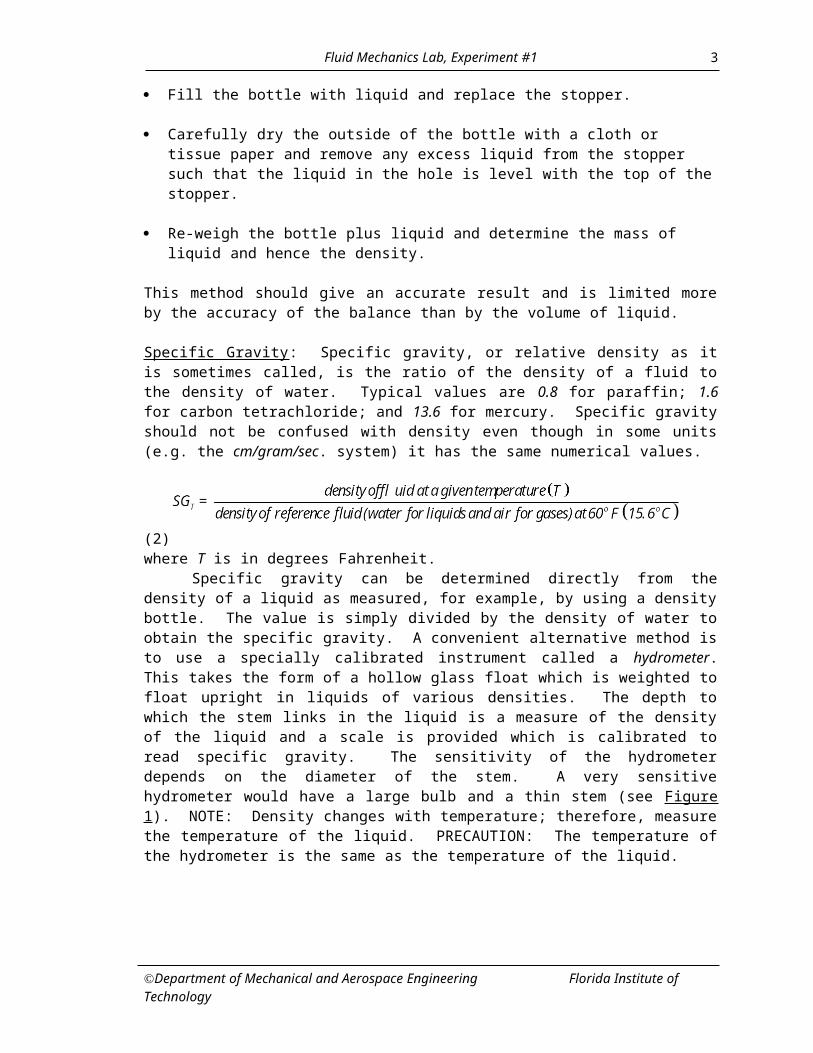
Carefully dry the outside of the bottle with a cloth or tissue paper and remove any excess liquid from the stopper such that the liquid in the hole is level with the top of the stopper.
Re-weigh the bottle plus liquid and determine the mass of liquid and hence the density.
This method should give an accurate result and is limited more by the accuracy of the balance than by the volume of liquid.
Specific Gravity: Specific gravity, or relative density as it is sometimes called, is the ratio of the density of a fluid to the density of water. Typical values are 0.8 for paraffin; 1.6 for carbon tetrachloride; and 13.6 for mercury. Specific gravity should not be confused with density even though in some units (e.g. the cm/gram/sec. system) it has the same numerical values.
(2)
where T is in degrees Fahrenheit.Specific gravity can be determined directly from the density of a liquid as measured, for
example, by using a density bottle. The value is simply divided by the density of water to obtain the specific gravity. A convenient alternative method is to use a specially calibrated instrument called a hydrometer. This takes the form of a hollow glass float which is weighted to float upright in liquids of various densities. The depth to which the stem links in the liquid is a measure of the density of the liquid and a scale is provided which is calibrated to read specific gravity. The sensitivity of the hydrometer depends on the diameter of the stem. A very sensitive hydrometer would have a large bulb and a thin stem (see Figure 1). NOTE: Density changes with temperature; therefore, measure the temperature of the liquid. PRECAUTION: The temperature of the hydrometer is the same as the temperature of the liquid.
Department of Mechanical and Aerospace Engineering Florida Institute of Technology
2
Fluid Mechanics Lab, Experiment #1
Figure 1. Types of hydrometer
Baume scale hydrometers (nonlinear) are used with liquids heavier than water, and American Petroleum Indrustries (API) hydrometers feature a linear scale for improved accuracy.
Degrees Baume = 145 - (3)
Degrees API = (4)
(5)
where T is in degrees Fahrenheit.
Procedure for determination of SG
Place one of the tall glass cylinders on the measuring surface, fill with a liquid, and allow air to rise to the top.
Carefully insert the hydrometer and allow it to settle in the center of the cylinder.
Department of Mechanical and Aerospace Engineering Florida Institute of Technology
3

Fluid Mechanics Lab, Experiment #1
Take care not to let it touch the sides, otherwise surface tension effects may cause errors.
When the hydrometer has settled, read the scale at the level of the free water surface (i.e. at the bottom of the meniscus; see Figure 1 insert).
PART II – VISCOSITY, (T,P)The most familiar property of a fluid is the viscosity. The viscosity is responsible for drag on aerospace vehicles, friction in pipes, and the destabilization/stabilization of some laminar flows.
Viscosity is a fluid property subject to changes in temperature and pressure. The viscosity of a liquid decreases with increasing temperature while the viscosity of a gas increases with increasing temperature. It is sufficient to recognize that viscous effects originate at the molecular level. In the presence of a velocity gradient normal to the mean flow, momentum exchange between adjacent fluid lamina result in a net decrease of momentum - fluid friction. This phenomenon occurs at the microscopic level and should not be confused with momentum transfer in turbulence, which occurs at the macroscopic level.
Popular science characterizes the viscosity of a fluid by the degree of "thickness" or "resistance" to flow. Water drains out of a sink much faster than an equivalent volume of molasses. In fact, this observation has been exploited by the petroleum industry as a means to quantify viscosity. For example, SAE 30 motor oil means that it took 30 seconds for a given quantity of the oil at a specified temperature to drain from a container (the container in this case is more appropriately a "Saybolt viscometer"). However, this is an oversimplification as viscosity does not have the units of seconds.
Viscosity is better defined as that property which relates an applied strain rate to the resulting shear stress and vice versa. It is usually beyond the scope of an undergraduate fluid mechanics course to develop a general relation between stress and strain since this requires the use of tensor analysis. However, students should recognize that a linear relation between stress and strain is a special case in fluid mechanics. In general, the relation between stress and strain in a fluid is written as
(6)
where is the shear stress and is the strain rate. There is not an a priori reason to suppose a linear relationship. In fact, viscosity may be a function of strain rate itself.
Effects of temperature
Gases: Viscosity increases with increasing temperature as seen in Sutherland's formula:
(7)
(8)
where µ is the coefficient of absolute viscosity, T is in K(elvin), and S = 110.4K.
Liquids: Viscosity decreases with increasing temperature
For water, A = -1.94 (9)
B = -4.80 [F.M. White, 1994]
Department of Mechanical and Aerospace Engineering Florida Institute of Technology
4

Fluid Mechanics Lab, Experiment #1
A Newtonian fluid is defined as a substance in which the shear stress in linearly proportional to the strain rate. Consider the flow between parallel plates as shown in Figure 2. A parcel of fluid is strained by the moving upper plate; hence, shear stresses are produced. For a Newtonian fluid, the relation between shear and stress reduces to
where is twice the strain rate, 2 . (10)
Note that this special geometry results in a linear velocity distribution; hence, is constant.
The deformation of a fluid parcel is represented by element A which, as it moves to the right, deforms to element B in Figure 2. This deformation is associated with the strain rate.
Figure 2. Strain in a fluid due to a moving boundary.
Non-Newtonian fluids may also be characterized by their stress-strain behavior. Table 1 contains a description of various rheological classifications, and Figure 3 contains a comparative plot of stress versus strain rate for a variety of rheological classifications.
RHEOLOGICAL CLASSIFICATIONClassification Characteristics
Newtonian: Stress is linearly proportional to strain.Bingham Plastic: Yield—Newtonian; stress is linearly proportional
to strain after initial applied yield strain.Dilatant: Stress increases with increasing strain rate.
Pseudo Plastic: Stress decreases with increasing strain rate.Rheopectic*: Stress increases with time – constant strain rate.Thixotropic*: Stress decreases with time – constant strain rate.
*not shown in plotTable 1. Rheological Classification
Department of Mechanical and Aerospace Engineering Florida Institute of Technology
5

Fluid Mechanics Lab, Experiment #1
Figure 3. Stress-strain behavior for various fluids.
Given an unknown fluid, the above classifications could be determined by imposing a strain rate and qualitatively sensing the resistance (stress). Slowly pouring the fluid out of a cup would simulate a relatively low strain rate while vigorous stirring would correspond to a high strain rate. For example, if the resistance (shear stress) to stirring "appeared" to decrease with more vigorous stirring (strain rate), the fluid would be classified a pseudoplastic. The phenomenon can be characterized by an apparent viscosity, , which is defined as
(11)
Department of Mechanical and Aerospace Engineering Florida Institute of Technology
6

Fluid Mechanics Lab, Experiment #1
Figure 4. Definition of Apparent Viscosity.
The definition is applied as indicated in Figure 4.
Measurement of viscosity of liquidsRotational viscometer: The absolute viscosity of liquids can be determined by using a rotational viscometer or a falling ball viscometer (see Figure 5).
Figure 5. Rotational Viscometer
Department of Mechanical and Aerospace Engineering Florida Institute of Technology
7

Fluid Mechanics Lab, Experiment #1
The apparatus is designed such that the velocity profile between the cylinder and wall is linear; therefore, the strain rate is constant for a given rotation speed of the inner cylinder. If the cylinder is driven by a falling weight as shown, the applied stress to the fluid will be constant (and known). Further, the strain rate, which is proportional to the rotation rate, , will be known. Hence, by applying different weights, the apparent viscosity for each strain rate can be determined.
For this circular Couette flow, we can determine the viscosity from the following relation:
(12)
where = dynamic viscosityr = radius of the cylinder pulleym = mass which produces a steady velocity URo = outer radius of cylinderRi = inner radius of cylinderL = length of the cylinderU = velocity of fall of the mass m
Procedure Fill the gap between the stationary and rotating cylinders with the fluid whose viscosity is to
be determined. Be sure the rotating cylinder is completely immersed in the fluid.
Apply different weights to the weight hanger and, in each case, measure the velocity of the fall (terminal velocity) by timing the fall through a known height.
Note the dimensions of the cylinders and pulley, etc.
Repeat the procedure for other fluids if necessary.
Falling Ball Viscometer: Another technique that requires a low Reynolds number flow is to infer the viscosity (Newtonian) from the rate at which a small sphere falls through a fluid (Falling Ball Viscometer). At very low Reynolds numbers (RD<<1), viscous forces dominate inertial forces. Hence, the nonlinear convective acceleration terms in the Navier-Stokes equations become negligible. As a result the governing equations are linear and solvable in closed form. Stokes solved the equations of motion for a sphere moving through a fluid using the low Reynolds number assumption – Stokes’ flow. The result:
F = 3π·µ·U·D (13)
Where F = net force acting on sphereU = velocity of sphereD = diameter of sphereµ = absolute viscosity
provided that
where ρ is the density of the fluid. (14)
Department of Mechanical and Aerospace Engineering Florida Institute of Technology
8

Fluid Mechanics Lab, Experiment #1
Assume first and then estimate the range for U.
Now consider a sphere falling through a stationary fluid (at a very low Reynolds number). The net force, F, acting on the sphere is the resultant of the weight, W, and buoyancy, FB, as shown in Figure 6. If the sphere is falling at a constant velocity, then acceleration is zero.
F=W-FB (15)Where W = mg, with m equal to the mass of the sphere and
(16)
where ρ is the density of the fluid.The net force must be equal to [15], hence
(17)
and solving for the viscosity
. (18)
Again, this equation is valid when the Reynolds number based on diameter is less than 1 [14]. If this condition is met, Equation [18] can be used to determine the viscosity of the fluid. The velocity, U, is found by timing the fall of the sphere over a specified distance. Note that the density of the fluid and the mass and diameter of the sphere must be known. When the Reynolds number is greater than 1, inertial forces begin to have more influence and the above technique is no longer valid.
Figure 6. Force diagram for a falling sphere.
Department of Mechanical and Aerospace Engineering Florida Institute of Technology
9

Fluid Mechanics Lab, Experiment #1
Procedure
Determine the density of the test fluid(s) and mass and diameter of the sphere(s). NOTE: The instructor may have done this already.
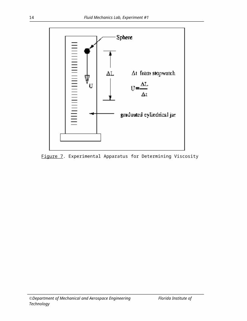
Drop the sphere into the cylinder of fluid. Time the fall of the sphere through a given distance and record. NOTE: Begin timing the fall several centimeters below the surface of the liquid. This will allow the speed of the sphere to reach equilibrium; otherwise the above theory is invalid.
Repeat several times for each fluid.
Repeat for several sphere diameters.
Figure 7. Experimental Apparatus for Determining Viscosity
Department of Mechanical and Aerospace Engineering Florida Institute of Technology
10

Fluid Mechanics Lab, Experiment #1
FALLING SPHERE VISCOMETER
Fluid Density ____________________________ Temperature ______________________
Run Mass
M(kg)
Diameter
D(m)
Distance
L (m)
Time
t (s)
Velocity
U (m/s)
ReynoldsNumber
RD
Viscosity
(Ns/m2)
Table 2. Suggested Presentation of Experimental Data
Suggested Presentations
Calculate the viscosity using Equations [12] and [18].
Calculate the Reynolds number by [14].
How does the diameter and mass of the sphere influence the measurement?
Plot F vs. U and comment on the variation of F with m and D.
Compare the viscosity values with standard table/graph values.
How do your values of viscosity compare between the two methods and with the accepted values for the given fluids found in your textbooks? (The instructor should be able to give the accepted viscosity values.)
Discuss the accuracy of the results and possible sources of errors.
Department of Mechanical and Aerospace Engineering Florida Institute of Technology
11

Fluid Mechanics Lab, Experiment #1
PART III – PRESSURE
Pressure measurement is important not only in fluid mechanics but in virtually every branch of engineering. There are a wide range of methods for measuring pressure and many of these employ hydrostatic principles. The following experiments illustrate some of the methods and, in particular, how columns of fluid can be used in various forms to measure pressure.
Most pressure gauges measure changes in pressure relative to atmospheric pressure. Pressures measured in this way have come to be known as gauge pressures and the term is generally used to indicate a pressure measured relative to any known datum value. Absolute pressure, on the other hand, is the pressure measured relative to absolute zero, i.e. a vacuum. Gauge pressures can be converted to absolute values by adding on the datum pressure.
Pressure is mostly measured by observing the deflection of a material subjected to the unknown pressure. That is, the effect of an imposed pressure is usually indicated by some form of displacement. Pressure is defined as the time rate of change in momentum flux of the fluid molecules randomly impacting a unit area surface. One can extend the concept to a point within the fluid (gas or liquid) where an imaginary surface would encounter the same momentum exchange. Hence, pressure is a point function defined as a force per unit area. Pressure has units of lb/in2 in the U.S. customary system and N/m2 in the SI system. Often, pressure is reported in terms of "inches of mercury" or "inches of water." These are not units of pressure! These units refer to the displacement of a fluid within a tube subjected to the unknown pressure.
U-Tube Manometer: The most common instrument for the measurement of pressure differences is the U-tube manometer. A glass of plastic tube is made into a "U" shape and filled with some liquid of known density as shown in Figure 8.
When pressure sources 1 and 2 are applied to the two open ends, the fluid on the low pressure side will rise to balance the applied pressure differential. The difference in liquid height, h, is proportional to the pressure difference by the relation
(19)
Figure 8. U-Tube Manometer
where L is the density of the manometer fluid and g is the acceleration of gravity. This is a form of the hydrostatic equation. It is this value of h that is reported in terms like "inches of water." If p2 = 0, then the manometer becomes a barometer. A mercury barometer is commonly used to measure atmospheric pressure, hence the reference to "inches of mercury." The high density of mercury relative to that of water allows for a practical size: on the order of 30 inches
Department of Mechanical and Aerospace Engineering Florida Institute of Technology
12

Fluid Mechanics Lab, Experiment #1
tall. On the other hand, a water barometer used to measure atmospheric pressure would need to be in excess of 410 inches tall.
Accuracy of the manometer illustrated in Figure 8 is limited by ones ability to read a displacement, h. Small pressure differences are difficult to resolve. Higher resolution (up to about 0.01 in) can be achieved by inclining one of the manometer legs as shown in Figure 9. The displacement of the fluid in the inclined manometer is "amplified" by a factor of 1/sin . Most inclined manometer scales are calibrated to reflect this amplification. Note that as approaches 90o, the inclined manometer reverts to that in Figure 8.
The manometer, combined with a special probe known as pitot static tube, can be used to infer the velocity of a moving stream. When speaking of fluid velocity, one usually refers to the velocity of fluid particles passing through a fixed point in space. In contrast, velocities in solid mechanics (i.e. your car going down the street) are generally specific to a given "particle." The relationship between velocity and pressure in a fluid can be derived from Newton's second law of motion. The result provides a means to determine fluid velocity based on pressure measurement for flow on a horizontal surface.. This relation for an incompressible fluid may be written as
(20)
where p0 is the stagnation pressure, p is the pressure as defined above (sometimes called static or piezometeric pressure) and the last grouping of terms on the right is called the dynamic pressure. You should recognize this as Bernoulli's equation. Note that the density term, , is that of the fluid in which the measurement is taking place and, in general, is different than the fluid density in the manometer measuring the pressures p0 and p. Many assumptions are made regarding this form of Bernoulli's equation. Most importantly: a) negligible pressure change due to elevation (i.e. all motion is confined to horizontal plane), b) incompressible flow (fluid particles do not change density), and c) steady flow (velocity at a point in the flow is invariant with time). Bernoulli's equation is analogous to conservation of energy where the total pressure represents total energy per unit volume, the static pressure is the potential energy per unit volume, and the dynamic pressure is the kinetic energy per unit volume.
Figure 9. Inclined Manometer
Bernoulli's equation may be used to infer the velocity at a point in a fluid. Solving for velocity yields
Department of Mechanical and Aerospace Engineering Florida Institute of Technology
13
Fluid Mechanics Lab, Experiment #1
(21)
A manometer can be used to measure the pressure difference (p0 - p). But it remains to determine a method to sense this pressure difference.
Figure 10. Measurement of Static and Total Pressure
The static pressure is due to the random impact of molecules; hence, a means to isolate the static pressure from the non-random motion (the velocity) is needed. This can be done by placing a small hole drilled normal to a surface running parallel to the flow as shown in Figure 10.
Measurement of the total pressure accounts for both the static and dynamic pressures; hence, a tube opening is placed into the oncoming flow. The principle here is to bring the flow to rest (stagnate) in the tube. Since the velocity becomes zero, Bernoulli's equation reduces to the total pressure being equal to the static pressure (only in a tube oriented in this way!). Note that the manometer fluid insures that the flow comes to rest. An apparatus of this type is called a pitot tube (also: stagnation tube, total head tube, total pressure probe). A device, which contains both a pitot tube and static pressure ports, is called a pitot-static tube. A pitot-static tube, shown in Figure 11, can be connected directly to a U-tube manometer and the velocity determined by substitution of the hydrostatic equation into Bernoulli's equation giving
(22)
Care should be taken not to confuse the two densities, L and , as they are different.
Mercury Barometer: The mercury barometer provides a means of measuring absolute pressure by using a column of mercury. An example of a simple mercury barometer is fitted to the bench and a diagram is shown in Figure 12. The barometer consists of a closed-end glass tube, which is filled
Department of Mechanical and Aerospace Engineering Florida Institute of Technology
14

Fluid Mechanics Lab, Experiment #1
Figure 11. Pitot Static Tube
with mercury such that all air is excluded, and then inverted so that the closed end is at the top. The weight of the mercury column is such that the column falls in the tube and a vacuum is formed at the top. A tiny amount of mercury vapor is formed in the gap, but for most purposes the pressure at the top of the column can be considered an absolute zero (i.e. a complete vacuum). If the top of the column is distance h above the free surface at plane 2, the pressure at that plane is given by the equation
p2 = p1 + gh (12)
where p2 is an absolute pressure. In our case p1 = 0, so the height h is a measure of the absolute pressure at plane 2. The only pressure acting on the free surface is atmospheric pressure so the height h is an absolute measure of atmospheric pressure. Atmospheric pressure varies from day to day, but a typical value gives a mercury column height of 760 mm.
Figure 12. Simple Mercury Barometer
Pressure Transducers: For digital data processing liquid column manometers are unsuitable. So, pressure transducers are commonly used. The transducers convert the pressure input to electrical voltage outputs. The general transducer has a high pressure chamber and a low pressure chamber separated by a diaphragm. The flexing of the diaphragm due to differential pressures in the two chambers is measured as a resistance (strain gage) or capacitance change. A suitable electronics
Department of Mechanical and Aerospace Engineering Florida Institute of Technology
15

Fluid Mechanics Lab, Experiment #1
(e.g. Wheatstone bridge) is used to measure the changes in terms of voltages. The transducer output voltages are generally small (in mv). So, amplifiers are used to gain the signal output. Figure 13 shows a Omega™ capacitance type pressure transducer used in our laboratory.
Figure 13: Pressure transducer
Procedure
Become familiar with the U-tube, multi-tube inclined, and digital manometers.
Measure the total pressure along the centerline of an air jet with the inclined and digital manometers and compare the results.
General Notes: Show a neat schematic of the experimental setup. Estimate ρ, μ, etc, for the laboratory conditions. Report your uncertainties of measurements.The pressure gages are calibrated using a Dead Weight Calibrator as shown in Figure 15.
Figure 15. Pressure Gage Calibrator
Department of Mechanical and Aerospace Engineering Florida Institute of Technology
16

Fluid Mechanics Lab, Experiment #1
NOTES
Department of Mechanical and Aerospace Engineering Florida Institute of Technology
17

Fluid Mechanics Lab, Experiment #1
NOTES
Department of Mechanical and Aerospace Engineering Florida Institute of Technology
18


![Civil Engineering Department - ack.edu.kw · 10. 15FCVE124 – Fluid Mechanics [ 3CH, 3 Lec, 2 Lab ] Fluid mechanics covers properties of fluids, manometers and pressure measurement,](https://static.fdocuments.us/doc/165x107/5e15c5b87883c13f891096fb/civil-engineering-department-ackedukw-10-15fcve124-a-fluid-mechanics-3ch.jpg)