Fluid Flow Projects - Bureau of Safety and Environmental ... · PDF fileFluid Flow Projects...
439
Fluid Flow Projects Advisory Board Meeting, October 26, 2011 77 th Fluid Flow Projects Advisory Board Meeting Welcome
Transcript of Fluid Flow Projects - Bureau of Safety and Environmental ... · PDF fileFluid Flow Projects...

Fluid Flow Projects
Advisory Board Meeting, October 26, 2011
77th Fluid Flow Projects Advisory Board Meeting
Welcome

Fluid Flow Projects Advisory Board Meeting, October 26, 2011
Safety Moment
Emergency Exits Assembly Point Tornado Shelter Campus Emergency Call 9-911 Campus Security, ext. 5555 or 918-
631-5555 Rest Rooms

Fluid Flow Projects Advisory Board Meeting, October 26, 2011
Introductory Remarks
77th Semi-Annual Advisory Board Meeting
Handout Combined Brochure and Slide Copy
Sign-Up List Please Leave Business Card at
Registration Table

Fluid Flow Projects Advisory Board Meeting, October 26, 2011
Team
Research Associates Cem Sarica (Director) Holden Zhang (Associate Director) Eduardo Pereyra (Research Associate) Abdel Al-Sarkhi (KFPMU – Visiting
Research Professor) Eissa Al-Safran (KU – Collaborator)

Fluid Flow Projects Advisory Board Meeting, October 26, 2011
Team …
Project Coordinator Linda Jones
Project Engineer Scott Graham
Research Technicians Craig Waldron Norman Stegall
Web Master Lori Watts

Fluid Flow Projects Advisory Board Meeting, October 26, 2011
Team …
TUFFP Research Assistants Feras Al-Ruhaimani (Ph.D.) – Kuwait Yasser Al-Saadi (MS) – Saudi Arabia Rosmer Brito (MS) – Venezuela Kiran Gawas (Ph.D.) – India Mujgan Guner (MS) – Turkey Hamid Karami (Ph.D.) – Iran Ge Yuan (MS) – PRC Wei Zheng (MS) – PRC

Fluid Flow Projects Advisory Board Meeting, October 26, 2011
Team …
Visiting Research Assistants Jinho Choi, SNU Hoyoung Lee, SNU

Fluid Flow Projects Advisory Board Meeting, October 26, 2011
Guests
Dr. Hoang Nhan, PetroVietnam University
Jerry Martin, Cameron Process Systems

Fluid Flow Projects Advisory Board Meeting, October 26, 2011
Agenda
8:30 Introductory Remarks 8:45 Progress Reports Executive Summary Effect of Pipe Inclination on Flow Characteristics
of High Viscosity Oil-Gas Two-Phase Flow 10:15 Coffee Break 10:30 Progress Reports Downward Two-Phase Stratified Flow for Highly
Viscous Oils Effect of Medium Oil Viscosity on Two-Phase Oil-
Gas Flow Behavior in Horizontal Pipes Characterization of High Viscosity Slug Flow in
Horizontal Pipes

Fluid Flow Projects Advisory Board Meeting, October 26, 2011
Agenda …
12:00 Lunch – Chouteau C 1:15 Progress Reports
Low Liquid Loading in Gas-Oil-Water Pipe Flow Effects of MEG on Multiphase Flow Behavior Modeling of Droplet Entrainment in Co-current
Annular Two-Phase Flow: A New Approach High Pressure Test Facility Construction Update
3:00 Coffee Break

Fluid Flow Projects Advisory Board Meeting, October 26, 2011
Agenda …
3:15 Progress Reports Liquid Loading of Gas Wells (Part 1) Liquid Loading of Gas Wells (Part 2) Simplified Transient Two-Phase
Modeling Unified Heat Transfer Modeling of
Gas-Oil-Water Pipe Flow

Fluid Flow Projects Advisory Board Meeting, October 26, 2011
Agenda …
4:25 TUFFP Business Report 4:40 Open Discussion 5:10 Adjourn 5:30 TUFFP/TUPDP Reception -
Atrium, ACAC

Fluid Flow Projects Advisory Board Meeting, October 26, 2011
Other Activities
October 25, 2011 TUHOP Meeting TUFFP Workshop Excellent Presentations Beneficial for Everybody
Facility Tour October 27, 2011 TUPDP Meeting

Fluid Flow Projects
Advisory Board Meeting, October 26, 2011
Executive Summary of Research Activities
Cem Sarica

Fluid Flow Projects Advisory Board Meeting, October 26, 2011
Current Projects
High Viscosity Multiphase Flow Low Liquid Loading Flow Up-scaling Studies Effects of MEG on Multiphase Flow Droplet Homo-phase Studies

Fluid Flow Projects Advisory Board Meeting, October 26, 2011
Current Projects …
Liquid Loading of Gas Wells Simplified Transient Modeling Unified Model Energy Minimization Modeling

Fluid Flow Projects Advisory Board Meeting, October 26, 2011
High Viscosity Multiphase Flow
Significance Discovery of High Viscosity Oil Reserves
Objective Better Prediction Models
Past Studies Gokcal (2005), (2008)
Indicated Poor Performance of Models for Viscosities Between 200 and 1000 cP
Observed Significantly Different Flow Behavior Dominance of Slug Flow
Developed New Drift Velocity and Translational Velocity Closure
Models New Slug Frequency Correlation

Fluid Flow Projects Advisory Board Meeting, October 26, 2011
High Viscosity Multiphase Flow
Past Studies … Kora (2010) Investigated Slug Liquid Holdup
No Significant Change for a Liquid Viscosity Range of 181 – 587 cp
Gregory et al. Correlation and Zhang et al. Model Perform better than Other Correlations
Developed New Closure Relationship

Fluid Flow Projects Advisory Board Meeting, October 26, 2011
High Viscosity Multiphase Flow …
Current Studies Inclination Angle Effect Investigation
(Jeyachandra) Progress
Data Acquisition and Analysis for Downward and Upward Flows (- 2° and +2°)
Evaluation Pressure Drop Models (Unified, Xiao and OLGA) Closure Relationships for Slugs Characteristics

Fluid Flow Projects Advisory Board Meeting, October 26, 2011
High Viscosity Multiphase Flow …
Current Studies … Holistic Analysis of Slug Flow
Characteristics in Horizontal Pipes (Al-Safran)
Transition from Stratified Smooth to Other Flow Patterns (Brito and Pereyra) Progress
Experimental and Model Comparison is Completed
Future Study Lower Oil Viscosities

Fluid Flow Projects Advisory Board Meeting, October 26, 2011
High Viscosity Multiphase Flow …
Current Studies … Medium Viscosity Study (20 cp – 200
cp) (Brito) Progress
Developed a Comprehensive Data Processing Model and Software
Thoroughly Tested and Calibrated Capacitance Sensors
Near Future Activity Testing After Fall 2011 ABM

Fluid Flow Projects Advisory Board Meeting, October 26, 2011
Low Liquid Loading Flow
Significance Wet Gas Transportation Holdup and Pressure Drop Prediction Corrosion Inhibitor Delivery (Top of the
Line Corrosion) Objectives Develop Better Predictive Tools

Fluid Flow Projects Advisory Board Meeting, October 26, 2011
Low Liquid Loading Flow …
Past TUFFP Studies Two-phase, Small Diameter, Low
Pressure Air-Water and Air-Oil 2-in. ID Pipe with ±2°Inclination Angles
from Horizontal Two-phase, Large Diameter, Low
Pressure Air-Water 6-in. ID and ±2°Inclination Angles from
Horizontal

Fluid Flow Projects Advisory Board Meeting, October 26, 2011
Low Liquid Loading Flow …
Past TUFFP Studies … Three-phase, Large Diameter, Low Pressure
Air-Mineral Oil-Water 6 in. ID, Horizontal Flow Findings
Observed and Described Flow Patterns and Discovered a New Flow Pattern
Acquired Significant Amount of Data on Various Parameters, Including Entrainment Fraction
Remaining Tasks Development of Flow Pattern Detection Model Development of Improved Closure Relationships

Fluid Flow Projects Advisory Board Meeting, October 26, 2011
Low Liquid Loading Flow …
Current Study (Gawas) Three-phase, Large Diameter, Low
Pressure Inclined Flow Air-Mineral Oil-Water 6 in. ID and ±2°Inclination Angles from
Horizontal Objectives
Acquire Similar Data as in Horizontal Flow Study
Develop Improved Closure Relationships

Fluid Flow Projects Advisory Board Meeting, October 26, 2011
Low Liquid Loading Flow …
Progress Design and Construction of a New Isokinetic
Device with Multiple Probes Droplet Field Image Capture
Near Future Activity Data Acquisition and Analysis

Fluid Flow Projects Advisory Board Meeting, October 26, 2011
Up-Scaling Studies
Significance Better Design and Operation
Objective Testing and Improvement of Existing
Models for Large Diameter and Relatively High Pressures
Past Studies Low Pressure and 6 in. ID Low Liquid
Loading (Fan and Dong) High Pressure 2 in. ID (Manabe)

Fluid Flow Projects Advisory Board Meeting, October 26, 2011
Up-Scaling Studies …
New High Pressure, Large Diameter Facility HAZOP SOP Preparation Third Party Review Chevron will Participate

Fluid Flow Projects Advisory Board Meeting, October 26, 2011
Up-Scaling Studies …
First Project Investigation of Low Liquid Loading
Flow of Two-phases in Large Diameter Horizontal and Inclined Flow at Elevated Pressures Progress
Instrumentation Decided Near Future Activity
Implementation Testing and Data Acquisition

Fluid Flow Projects Advisory Board Meeting, October 26, 2011
Effects of MEG on Multiphase Flow
Objectives Collect Flow Pattern, Holdup, Pressure
Drop Data on a 6 in. ID Pipe With and Without MEG
Benchmark Steady State Models and Document Errors
Propose Improvements If Needed

Fluid Flow Projects Advisory Board Meeting, October 26, 2011
Effects of MEG on Multiphase Flow
Progress Mr. Hamid Karami, Ph.D. Student Assigned to
the Project Literature Review Underway
Near Future Activity Test Matrix Flow Loop Modification

Fluid Flow Projects Advisory Board Meeting, October 26, 2011
Droplet Homo-phase Studies
Significance Better Predictive Tools Lead to Better Design
and Practices General Objective Development of Closure Relationships
Past Study Earlier TUFFP Study Showed
Entrainment Fraction (FE) is Most Sensitive Closure Parameter in Annular Flow
Developed New FE Correlation Utilizing In-situ Flow Parameters Limited Data, Especially for Inclined Flow Conditions

Fluid Flow Projects Advisory Board Meeting, October 26, 2011
Droplet Homo-phase Studies …
Current Study Liquid Entrainment in Annular Two-
Phase Flow in Inclined Pipes Objectives Develop Better Closure Relationships

Fluid Flow Projects Advisory Board Meeting, October 26, 2011
Droplet Homo-phase Studies …
Status Experimental Study is Completed Entrainment Fraction is Found to Vary
with Inclination Angle Performance Analysis of the Existing
Correlations is Completed Closure Relationship Development A New Relationship Developed Based on
TUFFP and Other Data

Fluid Flow Projects Advisory Board Meeting, October 26, 2011
Liquid Loading of Gas Wells
Objectives Explore Mechanism Controlling Onset
of Liquid Loading Investigate Effects of Well Deviation
on Liquid Loading Ge (Max) Yuan is Research Assistant

Fluid Flow Projects Advisory Board Meeting, October 26, 2011
Liquid Unloading from Gas Wells …
Past Studies Primarily on Droplet Transfer {Turner
(1969), Coleman (1991), etc.} Film Reversal {Barnea (1987), Veeken
(2009)} No Comprehensive Study on
Inclination Angle Effect

Fluid Flow Projects Advisory Board Meeting, October 26, 2011
Liquid Unloading from Gas Wells …
Progress Data Acquisition Complete
Near Future Activity Data Analysis Model Evaluation
Study will Continue with Ms. Guner in 2012

Fluid Flow Projects Advisory Board Meeting, October 26, 2011
Transient Modeling
Significance Industry has Capable All Purpose
Transient Software OLGA, PLAC, TACITE
Efforts are Well Underway to Develop Next Generation All Purpose Transient Simulators Horizon, LEDA
Need for a Simple Transient Flow Simulator

Fluid Flow Projects Advisory Board Meeting, October 26, 2011
Transient Modeling …
Objective Development and Testing of a Simple
and Fast Transient Flow Simulator Several TUFFP Studies Scoggins, Sharma, Dutta-Roy, Taitel,
Vierkandt, Sarica, Vigneron, Minami, Gokdemir, Zhang, Tengesdal, and Beltran

Fluid Flow Projects Advisory Board Meeting, October 26, 2011
Transient Modeling …
Current Study (Choi) Approach is Changed Drift Flux is Chosen Development of a Simplified Isothermal
Drift Flux Transient Model Simulator Structure Design Code Development (Explicit Solver)

Fluid Flow Projects Advisory Board Meeting, October 26, 2011
Transient Modeling …
Future Work Properties Determination from Look-
up Table Produced by PVTSim Extension of the Drift Flux Model to
Segregated Flow Patterns Inclusion of Heat Transfer Model Implicit Scheme Implementation

Fluid Flow Projects Advisory Board Meeting, October 26, 2011
Unified Model
Objective Develop and Maintain an Accurate and
Reliable Steady State Multiphase Simulator Past Studies Zhang et al. Developed “Unified Model” in
2002 for Two-phase Flow Became TUFFP’s Flagship Steady State Simulator Applicable for All Inclination Angles
“Unified Model was Extended to Three-phase in 2006

Fluid Flow Projects Advisory Board Meeting, October 26, 2011
Unified Model …
Current Projects Code and Software Improvement
Efforts Extension of Heat Transfer Model to
Three Phase Flow (Zheng) Progress
Literature Review Model Development Plan
Near Future Activity Model Development

Fluid Flow Projects Advisory Board Meeting, October 26, 2011
Multiphase Flow Modeling Using Energy Minimization Concept
Past Sharma (2009) Successfully Applied
the Concept to Oil/Water Flow Objective of Current Project Apply Energy Minimization Approach
for Gas/Liquid Flow Objective Function Determination
Energy Equation in Meso-Scale and Macro Scale
Definition of Constrain Functions Based on Gas/Liquid Physics

Fluid Flow Projects Advisory Board Meeting, October 26, 2011
Multiphase Flow Modeling Using Energy Minimization Concept …
Status Hoyoung Lee, Visiting Scholar from
SNU is Assigned to the Project Project was on Hold Due to Mr. Lee’s
Military Service Obligations in His Home Country

Fluid Flow Projects Advisory Board Meeting, October 26, 2011
Multiphase Flow Modeling Using Energy Minimization Concept …
Future Work Define the Energy Equations and
Constrains for Different Gas/Liquid Configurations
Identify Independent Variables Formulation of Minimization Problem Model Experimental Data Comparison

Fluid Flow Projects
Effect of Pipe Inclination on Flow Characteristics of High Viscosity Oil-Gas Two-Phase
Flow
Benin Chelinsky Jeyachandra
Advisory Board Meeting, October 26, 2011

Fluid Flow Projects
Outline
Objectives Introduction Experimental Program Flow Characteristics Test Results Model Comparison
Conclusions Recommendations
Advisory Board Meeting, October 26, 2011

Fluid Flow Projects
Objectives
Acquire Experimental Data on Flow Characteristics for High Viscosity Oil-Gas Two-Phase Flow Inclination Effects Viscosity Effects
Validate Models/Correlation with Experimental Results
Advisory Board Meeting, October 26, 2011

Fluid Flow Projects
Introduction
Increase in High Viscosity Oil Offshore Discoveries
Current Multiphase Flow Models Developed for Low Viscosity Oils
Horizontal Flow Experiments- Gokcal (2005,2008) and Kora (2010)
Multiphase Flows May Exhibit Significantly Different Behavior for Higher Viscosity Oils
Advisory Board Meeting, October 26, 2011

Fluid Flow Projects
Experimental Facility…
LaserProbe
Valves
CPU
Air
Air
1234.5
Zero Max Config EnterMin
CapacitanceProbe
Advisory Board Meeting, October 26, 2011

Fluid Flow Projects
Experimental Matrix
Superficial Liquid Velocity 0.1 – 0.8 m/s
Superficial Gas Velocity 0.1 – 3.5 m/s
Temperatures 21.1 – 37.8 °C (70 – 100 °F) 585 – 181 cP
Inclination -2° and +2° from Horizontal
Advisory Board Meeting, October 26, 2011

Fluid Flow Projects
Two Phase Flow Characteristics
Flow Pattern Pressure Gradient Average Liquid Holdup Slug Length Slug Frequency Slug Liquid Holdup Translational Velocity Drift Velocity
Advisory Board Meeting, October 26, 2011

Fluid Flow Projects
1. Flow Patterns
A. Downward Inclined Flow
Advisory Board Meeting, October 26, 2011

Fluid Flow Projects
Viscosity Effects- 585 cP Viscosity Oil-Air vs. Water-Air Downward Inclined Two-Phase Flow
Advisory Board Meeting, October 26, 2011
0.001
0.01
0.1
1
10
0.01 0.1 1 10 100
v SL (
m/s
)
vSG (m/s)
ElongatedBubbleSlug Flow
DB Slug
SS
SW
Annular

Fluid Flow Projects
Viscosity Effects- 181 cP Viscosity Oil-Air vs. Water-Air Downward Inclined Two-Phase Flow
Advisory Board Meeting, October 26, 2011
0.001
0.01
0.1
1
10
0.01 0.1 1 10 100
v SL (
m/s
)
vSG (m/s)
ElongatedBubbleSlug Flow
Stratified
DB Slug
SW
SS
Annular

Fluid Flow Projects
Inclination Effects- Horizontal vs. Downward Inclined 585 cP Viscosity Oil-Air Flow
Advisory Board Meeting, October 26, 2011
0.001
0.01
0.1
1
10
0.01 0.1 1 10 100
v SL (
m/s
)
vSG (m/s)
ElongatedBubble
Slug FlowDB Slug
EB Annular

Fluid Flow Projects
Downward Inclined Flow vs. TUFFP Model Prediction
Advisory Board Meeting, October 26, 2011
0.001
0.01
0.1
1
10
0.01 0.1 1 10 100
v SL (
m/s
)
vSG (m/s)
ElongatedBubble
Slug Flow
Dispersed
Intermittent
Stratified Annular
0.001
0.01
0.1
1
10
0.01 0.1 1 10 100
v SL (
m/s
)
vSG (m/s)
ElongatedBubbleSlug Flow
Stratified
Dispersed Bubble
Intermittent
Stratified
Annular
585 cP 181 cP

Fluid Flow Projects
Downward Inclined Flow vs. Barnea Model Prediction
Advisory Board Meeting, October 26, 2011
0.001
0.01
0.1
1
10
0.01 0.1 1 10 100
v SL (
m/s
)
vSG (m/s)
Slug
Elongated Bubble
Dispersed Bubble
Elongated Bubble
Stratified
Slug
Annular
0.001
0.01
0.1
1
10
0.01 0.1 1 10 100
v SL (
m/s
)
vSG (m/s)
Slug Flow
STRATIFIED
ElongatedBubble
Dispersed Bubble
Elongated Bubble
Stratified
Slug
Annular
585 cP 181 cP

Fluid Flow Projects
1. Flow Patterns
B. Upward Inclined Flow
Advisory Board Meeting, October 26, 2011

Fluid Flow Projects
Viscosity Effects- 585 cP Viscosity Oil-Air vs. Water-Air Two-Phase Flow
Advisory Board Meeting, October 26, 2011
0.001
0.01
0.1
1
10
0.01 0.1 1 10 100
v SL (
m/s
)
vSG (m/s)
Annular
Elongated Bubble
Slug Flow
EB
DB
Slug Annular
ST

Fluid Flow Projects
Inclination Effects- Horizontal vs. Upward Inclined 585 cP Viscosity Oil-Air Flow
Advisory Board Meeting, October 26, 2011
0.001
0.01
0.1
1
10
0.01 0.1 1 10 100
v SL (
m/s
)
vSG (m/s)
Elongated Bubble
Slug Flow
Annular
DB
EB
Slug
Annular

Fluid Flow Projects
Downward Inclined Flow vs. TUFFP Model Prediction
Advisory Board Meeting, October 26, 2011
0.001
0.01
0.1
1
10
0.01 0.1 1 10 100
v SL (
m/s
)
vSG (m/s)
ElongatedBubble
Slug Flow
Annular
Dispersed Bubble
Intermittent
Annular
S 0.001
0.01
0.1
1
10
0.01 0.1 1 10 100
v SL (
m/s
)
vSG (m/s)
Slug Flow
Elongated Bubble
Annular
Dispersed
Intermittent
Annular
S
585 cP 181 cP

Fluid Flow Projects
Upward Inclined Flow vs. Barnea Model Prediction
Advisory Board Meeting, October 26, 2011
0.001
0.01
0.1
1
10
0.01 0.1 1 10 100
v SL (
m/s
)
vSG (m/s)
ElongatedBubble
Slug Flow
Annular
Dispersed Bubble
Elongated Bubble
Slug
Annular
0.001
0.01
0.1
1
10
0.01 0.1 1 10 100
v SL (
m/s
)
vSG (m/s)
ElongatedBubble
Slug
Annular
Dispersed Bubble
Elongated Bubble
Slug
Annular
585 cP 181 cP

Fluid Flow Projects
2. Pressure Gradient
A. Downward Inclined Flow
Advisory Board Meeting, October 26, 2011

Fluid Flow Projects
Inclination Effects- Pressure Gradients for vSL=0.1 m/s
Advisory Board Meeting, October 26, 2011
0
200
400
600
800
1000
1200
0 1 2 3 4 5 6
dP/d
L(Pa
/m)
vSG (m/s)
585 cP372 cP256 cP181 cP585 cp 0181 cP
µO=0.587 Pa·s µO=0.378 Pa·s µO=0.257 Pa·s µO=0.181 Pa·s µO=0.587 Pa·s (0°) µO=0.181 Pa·s (0°)

Fluid Flow Projects
Inclination Effects- Pressure Gradients for vSL=0.8 m/s
Advisory Board Meeting, October 26, 2011
0
1000
2000
3000
4000
5000
6000
7000
8000
0 1 2 3 4 5 6
dP/d
L(Pa
/m)
vSG (m/s)
585 cP
372 cP
256 cP
181 cP
585 cp 0
181 cP o
µO=0.587 Pa·s µO=0.378 Pa·s
µO=0.257 Pa·s µO=0.181 Pa·s
µO=0.587 Pa·s (0°)
µO=0.181 Pa·s (0°)

Fluid Flow Projects
Error Analysis
Correlation/Model
Statistical Parameters
ε1 (%) ε2 (%) ε3 (%) ε4 (Pa/m)
ε5 (Pa/m)
ε6 (Pa/m)
TUFFP Unified
Model
-16.51 20.46 20.12 -129.91 285.89 368.10
OLGA-S
-42.49 42.60 21.14 -607.49 611.64 345.15
Xiao (1990)
-37.29 38.33 21.865 -511.37 556.23 413.03
Advisory Board Meeting, October 26, 2011

Fluid Flow Projects
2. Pressure Gradient
B. Upward Inclined Flow
Advisory Board Meeting, October 26, 2010

Fluid Flow Projects
Inclination Effects- Pressure Gradients for vSL=0.1 m/s
Advisory Board Meeting, October 26, 2011
0
200
400
600
800
1000
1200
0 1 2 3 4 5 6
dP/d
L(Pa
/m)
vSG (m/s)
585 cP
372 cP
256 cP
181 cP
585 cp Horizontal
181 cp Horizontal
µO=0.587 Pa·s
µO=0.378 Pa·s
µO=0.257 Pa·s
µO=0.181 Pa·s
µO=0.587 Pa·s (0°)
µO=0.181 Pa·s (0°)

Fluid Flow Projects
Inclination Effects- Pressure Gradients for vSL=0.8 m/s
Advisory Board Meeting, October 26, 2011
0
1000
2000
3000
4000
5000
6000
7000
8000
9000
0 1 2 3 4 5 6
dP/d
L(Pa
/m)
vSG (m/s)
0.585 cP
372 cP
256 cP
181 cP
585 hori
181 hori
µO=0.587 Pa·s
µO=0.378 Pa·s
µO=0.257 Pa·s
µO=0.181 Pa·s
µO=0.587 Pa·s (0°)
µO=0.181 Pa·s (0°)

Fluid Flow Projects
Error Analysis
Correlation/Model Statistical Parameters
ε1 (%) ε2 (%) ε3 (%) ε4 (Pa/m)
ε5 (Pa/m)
ε6 (Pa/m)
TUFFP Unified Model -2.45 5.67 6.31 -34.46 131.04 192.37
OLGA-S -10.64 12.15 9.52 -309.32 320.95 321.75
Xiao (1990) -14.32 16.26 12.95 -400.16 426.56 469.45
Advisory Board Meeting, October 26, 2011

Fluid Flow Projects
3. Slug Liquid Holdup
A. Downward Inclined Flow
Advisory Board Meeting, October 26, 2011

Fluid Flow Projects
Velocity Effects- Slug Liquid Holdup for 585 cP Viscosity Oil-Air Flow
Advisory Board Meeting, October 26, 2011
0.8
0.82
0.84
0.86
0.88
0.9
0.92
0.94
0.96
0.98
1
0 0.5 1 1.5 2 2.5 3 3.5 4
HLL
S (-
)
vSG (m/s)
0.1 m/s
0.2 m/s
0.3 m/s
0.5 m/s
0.8 m/s
vSL=0.1 m/s
vSL=0.3 m/s
vSL=0.5 m/s
vSL=0.8 m/s
vSL=0.2 m/s

Fluid Flow Projects
Inclination Effects- Downward and Horizontal Slug Liquid Holdup for
vSL= 0.3 m/s
Advisory Board Meeting, October 26, 2011
0.8
0.82
0.84
0.86
0.88
0.9
0.92
0.94
0.96
0.98
1
0 0.5 1 1.5 2 2.5 3 3.5 4 4.5 5
HLL
S (-
)
vm (m/s)
585 cP
181 cP
581 cPhorizontal181 cP-Horizontal
µO=0.587 Pa·s
µO=0.587 Pa·s (0°)
µO=0.181 Pa·s (0°)
µO=0.181 Pa·s

Fluid Flow Projects
3. Slug Liquid Holdup
B. Upward Inclined Flow
Advisory Board Meeting, October 26, 2011

Fluid Flow Projects
Velocity Effects- Slug Liquid Holdup for 585 cP Viscosity Oil-Air Flow
Advisory Board Meeting, October 26, 2011
0.8
0.82
0.84
0.86
0.88
0.9
0.92
0.94
0.96
0.98
1
0 0.5 1 1.5 2 2.5 3 3.5 4 4.5
HLL
S (-
)
vSG (m/s)
0.1 m/s
0.3 m/s
0.5 m/s
0.8 m/s
vSL=0.1 m/s
vSL=0.3 m/s
vSL=0.5 m/s
vSL=0.8 m/s

Fluid Flow Projects
Inclination Effects- Upward and Horizontal Slug Liquid Holdup for
vSL= 0.3 m/s
Advisory Board Meeting, October 26, 2011
0.8
0.82
0.84
0.86
0.88
0.9
0.92
0.94
0.96
0.98
1
0 1 2 3 4 5 6 7 8
HLL
S (-
)
vm (m/s)
585 cP
181 cP
585 cP-horizontal
181 cP- Horizontal
µO=0.587 Pa·s
µO=0.587 Pa·s (0°)
µO=0.181 Pa·s (0°)
µO=0.181 Pa·s

Fluid Flow Projects
4. Slug Frequency
A. Downward Inclined Flow
Advisory Board Meeting, October 26, 2011

Fluid Flow Projects
Velocity Effects- Slug Frequency for 585 cP Viscosity Oil-Air Flow
Advisory Board Meeting, October 26, 2011
0.0
0.5
1.0
1.5
2.0
2.5
3.0
0 0.5 1 1.5 2 2.5 3 3.5 4 4.5 5
n s (1
/s)
vSG(m/s)
0.1 m/s
0.2 m/s
0.3 m/s
0.5 m/s
0.8 m/s
vSL=0.1 m/s
vSL=0.3 m/s
vSL=0.5 m/s
vSL=0.8 m/s
vSL=0.2 m/s

Fluid Flow Projects
Downward Slug frequency Comparison with Horizontal for vSL = 0.3 m/s
Advisory Board Meeting, October 26, 2011
0
0.5
1
1.5
2
2.5
0 0.5 1 1.5 2 2.5 3 3.5 4
n s (1
/s)
vSG (m/s)
586 cP
181 cP
585 cP (horizontal)
181 cP (Horizontal)
µO=0.587 Pa·s
µO=0.587 Pa·s (0°)
µO=0.181 Pa·s (0°)
µO=0.181 Pa·s

Fluid Flow Projects
4. Slug Frequency
B. Upward Inclined Flow
Advisory Board Meeting, October 26, 2011

Fluid Flow Projects
Velocity Effects- Slug Frequency for 585 cP Viscosity Oil-Air Flow
Advisory Board Meeting, October 26, 2011
0
1
2
3
4
5
6
0 0.5 1 1.5 2 2.5 3 3.5 4 4.5
n s (1
/s)
vSG (m/s)
0.1 m/s
0.3 m/s
0.5 m/s
0.8 m/s
vSL=0.1 m/s
vSL=0.3 m/s
vSL=0.5 m/s
vSL=0.8 m/s

Fluid Flow Projects
Upward Slug frequency Comparison with Horizontal for vSL = 0.3 m/s
Advisory Board Meeting, October 26, 2011
0
0.5
1
1.5
2
2.5
3
0 0.5 1 1.5 2 2.5 3 3.5 4 4.5 5
n s (1
/s)
vSG (m/s)
585 cP
181 cP
585 cP ( Horizontal)
181 cP
µO=0.587 Pa·s
µO=0.587 Pa·s (0°)
µO=0.181 Pa·s (0°)
µO=0.181 Pa·s

Fluid Flow Projects
5. Slug Length
A. Downward Inclined Flow
Advisory Board Meeting, October 26, 2011

Fluid Flow Projects
Viscosity Effects in Slug Length
Advisory Board Meeting, October 26, 2011
0
2
4
6
8
10
12
14
16
18
0 0.5 1 1.5 2 2.5 3 3.5 4
L s/D
(-)
vSG (m/s)
586 cP
181 cP
µO=0.587 Pa·s
µO=0.181 Pa·s

Fluid Flow Projects
Comparison of Downward Inclined and Horizontal Slug Length for 585 cP Viscosity
Oil–Air Flow
Advisory Board Meeting, October 26, 2011
0
2
4
6
8
10
12
14
0 0.5 1 1.5 2 2.5 3 3.5 4
L s/D
(-)
vSG (m/s)
vSL - 0.8 m/s
vSL- 0.1 m/s
vSL - 0.1 m/s(Horizontal)vSL - 0.8 m/s(Horizontal)
vSL=0.8 m/s
vSL=0.1 m/s
vSL=0.1 m/s (0°)
vSL=0.8 m/s (0°)

Fluid Flow Projects
5. Slug Length
B. Upward Inclined Flow
Advisory Board Meeting, October 26, 2011

Fluid Flow Projects
Viscosity Effects in Slug Length
Advisory Board Meeting, October 26, 2011
0
2
4
6
8
10
12
14
16
0 0.5 1 1.5 2 2.5 3 3.5 4 4.5 5
L s/D
(-)
vSG (m/s)
585 cP
181 cP
µO=0.587 Pa·s
µO=0.181 Pa·s

Fluid Flow Projects
Comparison of Downward Inclined and Horizontal Slug Length for 585 cP Viscosity
Oil–Air Flow
Advisory Board Meeting, October 26, 2011
0
2
4
6
8
10
12
0 0.5 1 1.5 2 2.5 3 3.5 4 4.5
L s/D
(-)
vSG (m/s)
0.1 m/s
0.8 m/s
0.1 m/s(Horizontal)0.8 m/s(horizontal)
vSL=0.1 m/s
vSL=0.8 m/s
vSL=0.1 m/s (0°)
vSL=0.8 m/s (0°)

Fluid Flow Projects
6. Translational Velocity
A. Downward Inclined Flow
Advisory Board Meeting, October 26, 2011

Fluid Flow Projects
Inclination Effects in Translational Velocity
Advisory Board Meeting, October 26, 2011
0
1
2
3
4
5
6
7
0.0 0.5 1.0 1.5 2.0 2.5 3.0 3.5 4.0 4.5 5.0
v T (m
/s)
vM (m/s)
585 cP
181 cP
585 cP-horizontal
181 cP-horizontal
µO=0.587 Pa·s
µO=0.181 Pa·s
µO=0.587 Pa·s(0°)
µO=0.181 Pa·s (0°)

Fluid Flow Projects
6. Translational Velocity
B. Upward Inclined Flow
Advisory Board Meeting, October 26, 2011

Fluid Flow Projects
Inclination Effects in Translational Velocity
Advisory Board Meeting, October 26, 2011
0
2
4
6
8
10
12
0 1 2 3 4 5 6 7 8
v T (m
/s)
vM (m/s)
585 cP181 cP585 cP-Horizontal181 cP-Horizontal
µO=0.587 Pa·s
µO=0.587 Pa·s (0°) µO=0.181 Pa·s (0°)
µO=0.181 Pa·s

Fluid Flow Projects
Conclusion
Experimentation for Two Phase Flow Characteristics on -2° and +2° Inclination Completed
Flow Characteristics Flow Pattern Pressure Gradient Slug Liquid Holdup Slug Length Slug Frequency Translational Velocity Drift Velocity
Advisory Board Meeting, October 26, 2011

Fluid Flow Projects
Questions/Comments
Advisory Board Meeting, October 26, 2011

Fluid Flow Projects
Advisory Board Meeting, October 26, 2011
Downward Two-Phase Stratified Flow for Highly Viscous Oils
R. Brito, E. Pereyra and C. Sarica

Fluid Flow Projects Advisory Board Meeting, October 26, 2011
Outline
Introduction Objective Experimental Program and Results Wave Pattern for Stratified Region Stratified Smooth – Stratified Wavy
Transition Stratified – Non-Stratified Transition Conclusions Future Tasks

Fluid Flow Projects Advisory Board Meeting, October 26, 2011
Introduction
Observed Flow Pattern vs. Shoham (1982) Data
0.001
0.01
0.1
1
10
0.01 0.1 1 10 100
VSL
(m/s
)
VSG (m/s)
D-B SL
ANN
S-W S-S
Shoham (1982)
Transition Lines

Fluid Flow Projects Advisory Board Meeting, October 26, 2011
Introduction
Observed Flow Pattern vs. Shoham (1982) Data
0.001
0.01
0.1
1
10
0.01 0.1 1 10 100
VSL
(m/s
)
VSG (m/s)
EB
SL
D-B SL
ANN
S-S S-W
S-S
SS

Fluid Flow Projects Advisory Board Meeting, October 26, 2011
Objective
Experimental and Theoretical Study of Transition Phenomenon from Stratified-Smooth to Stratified-Wavy for Downward flow (-2°) and High Viscosity Oil (181 cP)

Fluid Flow Projects Advisory Board Meeting, October 26, 2011
Outline
Introduction Objective Experimental Program and Results

Fluid Flow Projects Advisory Board Meeting, October 26, 2011
Experimental Program
2-in ID High Viscosity Indoor Facility Superficial Liquid Velocity 0.01 – 0.8 m/s
Superficial Gas Velocity 0 – 7.2 m/s
Inclination Downward (-2°)

Fluid Flow Projects Advisory Board Meeting, October 26, 2011
Test Liquid: Citgo 220 Mineral Oil Gravity: 27.6 °API Density: 889 kg/m3 @ 60 °F Pour Point: 10 °F Flash Point: 482 °F Viscosity: 181 cP @ 100 °F
Test Gas: Air
Experimental Program …

Fluid Flow Projects Advisory Board Meeting, October 26, 2011
Experimental Results
Observed Flow Pattern vs. Shoham (1982) Data
0.001
0.01
0.1
1
10
0.01 0.1 1 10 100
VSL
(m/s
)
VSG (m/s)
EBSLSSSW
D-B SL
ANN
S-S S-W
0.09 m/s 0.07 m/s 0.05 m/s 0.03 m/s

Fluid Flow Projects Advisory Board Meeting, October 26, 2011
Outline
Introduction Objective Experimental Program and Results Wave Pattern for Stratified Region

Fluid Flow Projects Advisory Board Meeting, October 26, 2011
Wave Pattern
Andritsos and Hanratty (1986) Studied the Interfacial Instability of Stratified
Horizontal Flow µo= 1 cP – 70 cP Three Types of Instabilities has been Observed
2-D Small Amplitude Waves Irregular Large Amplitude Waves Atomization
2-D Waves Region Attenuates as Liquid Viscosity Increases

Fluid Flow Projects Advisory Board Meeting, October 26, 2011
Wave Pattern…
Interfacial Instabilities after Andritsos and Hanratty (1986)

Fluid Flow Projects Advisory Board Meeting, October 26, 2011
Wave Pattern…
Breaking Waves vSG=4.5 m/s and vSL=0.09 m/s
Long Waves vSG=5.5 m/s and vSL=0.03 m/s
Large Amplitude Waves

Fluid Flow Projects Advisory Board Meeting, October 26, 2011
Wave Pattern…
Film Thickness Time Traces for vSG=4.5 m/s
h L/D
[-]
Time [s]

Fluid Flow Projects Advisory Board Meeting, October 26, 2011
Wave Pattern… h L
/D[-
]
Time [s]
Film Thickness Time Traces for vSG=4.5 m/s

Fluid Flow Projects Advisory Board Meeting, October 26, 2011
Wave Pattern… h L
/D[-
]
Time [s]
Film Thickness Time Traces for vSL=0.03 m/s

Fluid Flow Projects Advisory Board Meeting, October 26, 2011
Outline
Introduction Objective Experimental Program and Results Wave Pattern for Stratified Region Stratified Smooth – Stratified Wavy
Transition

Fluid Flow Projects Advisory Board Meeting, October 26, 2011
Stratified Smooth – Stratified Wavy
Observed Flow Pattern vs. Shoham (1982) Data
0.001
0.01
0.1
1
10
0.01 0.1 1 10 100
VSL
(m/s
)
VSG (m/s)
SS
SW
D-B SL
ANN
S-S S-W
Waves Interfacial Shear
(Jeffrey)
Gravity Waves (Barnea)

Fluid Flow Projects Advisory Board Meeting, October 26, 2011
Stratified Smooth – Stratified Wavy …
5.1≥=L
L
hgvFr
Barnea et al. (1982) Waves Generated by Gravity in Downward Flow

Fluid Flow Projects Advisory Board Meeting, October 26, 2011
Stratified Smooth – Stratified Wavy …
Froude Number Criterion Sensitivity
0.0001
0.001
0.01
0.1
1
10
0.001 0.01 0.1 1 10 100
V SL (
m/s
)
VSG (m/s)
S-S
S-W
Fr=0.5
Fr=1.5
Fr=2.2
S-S
S-W

Fluid Flow Projects Advisory Board Meeting, October 26, 2011
Stratified Smooth – Stratified Wavy…
( ) 5.0cos4
−≥
LGL
GLLG vs
gv
ρρθρρµ
Jeffrey’s Theory
s: fraction of wave exposed to the action of the wind
C
VG
Potential Flow Field Pressure and Shear Forces > Viscous Dissipation of Waves

Fluid Flow Projects Advisory Board Meeting, October 26, 2011
Stratified Smooth – Stratified Wavy …
Sheltering Coefficient Sensitivity
0.0001
0.001
0.01
0.1
1
10
100
0.001 0.01 0.1 1 10 100
V SL (
m/s
)
VSG (m/s)
S-SS-WS=0.01S=0.3S=1
S-S
S-W

Fluid Flow Projects Advisory Board Meeting, October 26, 2011
Outline
Introduction Objective Experimental Program and Results Wave Pattern for Stratified Region Stratified Smooth - Stratified Wavy
Transition Stratified – Non-Stratified Transition

Fluid Flow Projects Advisory Board Meeting, October 26, 2011
Stratified – Non-Stratified
lU
lF
Slug Flow Stability Analysis (Zhang et al., 2003) lF / lU > 1 Transition to Stratified or
Annular Flow

Fluid Flow Projects Advisory Board Meeting, October 26, 2011
Stratified – Non-Stratified …
Stability of the Gas-Liquid Interface Kelvin-Helmholtz Analysis Two Fluid Model Linearization Perturb the Linear Model with a
Monochromatic Wave
( ) ( ) ( )
−
+−<−
L
LLLLG
dhdA
AHHKvv θcosgρρρρρ)1(ρGL
GLGL

Fluid Flow Projects Advisory Board Meeting, October 26, 2011
Stratified – Non-Stratified …
Stability of the Gas-Liquid Interface
Calculate hL/d
Critical Velocity
Stable Interface? vG-vL<vc
ST Yes
N-ST No
vSL , vSG , ρL , µL , ρG , µG , d , ε/d , β
( ) 0sin11=−−
+++− βg ρρ
AASτ
ASτ
ASτ
GLGL
iiG
GG
L
LL
( ) ( ) ( )
−
+−=
L
LLLC
dhdA
AHHKv θcosgρρρρρ)1(ρGL
GLGL

Fluid Flow Projects Advisory Board Meeting, October 26, 2011
Stability Analysis Models
Model Considerations K Taitel &Dukler (1976)
Suction force ≥ Gravity Force
IKH
Do not consider viscous effect on stability analysis.
K=1
VKH Barnea (1991)
Consider the viscous effect using the shear stresses between the
wall and each phase.
−=
dh1 LK
( )( ) ( )
L
L
IVV
dhdA
ACCK θcosg
ρρρ1
GL
2
−−
−=

Fluid Flow Projects Advisory Board Meeting, October 26, 2011
Stability Analysis Model …
Taitel and Dukler (1976) Sensitivity Analysis
0.001
0.010
0.100
1.000
10.000
0.010 0.100 1.000 10.000 100.000
V SL (
m/s
)
VSG (m/s)
µo= 1 cP ; θ=0°
µo= 1 cP ; θ=-2°
µo= 181 cP ; θ=0°
µo= 181 cP ; θ=-2°

Fluid Flow Projects Advisory Board Meeting, October 26, 2011
Stability Analysis Model …
Taitel and Dukler (1976) Sensitivity Analysis
0.001
0.010
0.100
1.000
10.000
0.010 0.100 1.000 10.000 100.000
V SL (
m/s
)
VSG (m/s)
µo= 1 cP ; θ=0°
µo= 1 cP ; θ=-2°
µo= 181 cP ; θ=0°
µo= 181 cP ; θ=-2°

Fluid Flow Projects Advisory Board Meeting, October 26, 2011
Stratified – Non-Stratified …
Model Comparison
ST
N-ST

Fluid Flow Projects Advisory Board Meeting, October 26, 2011
Outline
Introduction Objective Experimental Program and Results Wave Pattern for Stratified Region Stratified Smooth to Stratified Wavy
Transition Stratified to Non Stratified Transition Conclusions

Fluid Flow Projects Advisory Board Meeting, October 26, 2011
Conclusions
2-D Small Amplitude Waves Do not Occur for a High Viscosity Oil (181 cP)
Gravity Waves Have not been Observed for Downward flow (-2°) and High Viscosity Oil (181 cP)
Barnea et al. (1982) Does not Apply for the Considered High Viscosity Oil

Fluid Flow Projects Advisory Board Meeting, October 26, 2011
Conclusions …
Transition from Stratified to Dispersed Bubble Has not been Observed as Water-Air Two-Phase Flow
None of the Model are Completely Satisfactory and Further Modeling Work is Required

Fluid Flow Projects Advisory Board Meeting, October 26, 2011
Future Tasks
Further Experiments Will be Run for Different Medium Oil Viscosities to Verify the Transition from Stratified-Smooth to Stratified-Wavy (Summer-2012)

Fluid Flow Projects Advisory Board Meeting, October 26, 2011
Thanks …

Fluid Flow Projects Advisory Board Meeting, October 26, 2011
Questions

Fluid Flow Projects
Advisory Board Meeting, October 26, 2011
Effect of Medium Oil Viscosity on Two-Phase Oil-Gas Flow Behavior
in Horizontal Pipes
Rosmer Brito

Fluid Flow Projects Advisory Board Meeting, October 26, 2011
Outline
Objectives Experimental Program Capacitance Sensor Calibration Data Acquisition and Processing Uncertainty Analysis Future Tasks

Fluid Flow Projects Advisory Board Meeting, October 26, 2011
General Objective
Experimental and Modeling Study of Oil-Gas Two Phase Flow to Investigate the Effects of Medium Viscosity Oil (33 cP - 129 cP) Flow Pattern Pressure Drop Liquid Holdup Slug Characteristics

Fluid Flow Projects Advisory Board Meeting, October 26, 2011
Specific Objective
Data Analysis Process
Results Quality Results Consistency
Time Random Error

Fluid Flow Projects Advisory Board Meeting, October 26, 2011
Specific Objectives …
Uncertainty Analysis for Each Data Point (vSLi, vSGi) Flow Conditions Fluid Properties Pressure Gradient Slug Characteristics

Fluid Flow Projects
Advisory Board Meeting, October 26, 2011
Experimental Program

Fluid Flow Projects Advisory Board Meeting, October 26, 2011
Experimental Facility
2-in ID High Viscosity Indoor Experimental Facility Test Section Metering Section Heating System Cooling System

Fluid Flow Projects Advisory Board Meeting, October 26, 2011
Test Oil Characteristics
Test Liquid: DN-20 Mineral Oil Gravity: 30.5 °API Density: 873 kg/m3 @ 60 °F Surface Tension: 27.5 dynes/cm Pour Point: -5 °F Flash Point: 435 °F
Test Gas: Air

Fluid Flow Projects Advisory Board Meeting, October 26, 2011
Test Oil Characteristics …
70 °F ; 129 cP
85 °F ; 86 cP
105 °F ; 50 cP 120 °F ; 33 cP
0
50
100
150
200
250
300
350
400
0 50 100 150 200
Oil
Visc
osity
(cP)
Temperature (°F)
Oil Viscosity vs. Temperature Curve

Fluid Flow Projects Advisory Board Meeting, October 26, 2011
Experimental Matrix
Superficial Liquid Velocity 0.01 – 3 m/s
Superficial Gas Velocity 0.1 – 5 m/s
Inclination Horizontal

Fluid Flow Projects Advisory Board Meeting, October 26, 2011
Experimental Matrix …
Flow Pattern Map 33 cP. TUFFP Unified Model
STR
ANN
INT
D-B

Fluid Flow Projects Advisory Board Meeting, October 26, 2011
Experimental Matrix …
Flow Pattern Map 129 cP. TUFFP Unified Model
STR
ANN
INT
D-B

Fluid Flow Projects Advisory Board Meeting, October 26, 2011
Experimental Matrix …
Flow Pattern Map 33 cP. Barnea Model
SS
IN
ANN EB
DB

Fluid Flow Projects Advisory Board Meeting, October 26, 2011
Experimental Matrix …
Flow Pattern Map 129 cP. Barnea Model
SS
IN
ANN EB
DB

Fluid Flow Projects
Advisory Board Meeting, October 26, 2011
Capacitance Sensor

Fluid Flow Projects Advisory Board Meeting, October 26, 2011
Capacitance Sensor
Ring Type Capacitance Sensor
Capacitance Sensors Location

Fluid Flow Projects Advisory Board Meeting, October 26, 2011
Capacitance Sensor Static Calibration
Static Calibration

Fluid Flow Projects Advisory Board Meeting, October 26, 2011
Capacitance Sensor Static Calibration …
𝑉′ =𝑉𝑟𝑟𝑟𝑟 − 𝑉𝑚𝑚𝑚
𝑉𝑚𝑟𝑚 − 𝑉𝑚𝑚𝑚
Static Calibration Curve

Fluid Flow Projects Advisory Board Meeting, October 26, 2011
Fluid Temperature Effect
0
1
2
3
4
5
70 80 90 100
Volta
ge (V
)
Fluid Temperature (°F)
FULL PIPE
960 CC
HALF PIPE
300 CC
EMPTY PIPE
∆V
Output Voltage vs. Fluid Temperature Curve

Fluid Flow Projects Advisory Board Meeting, October 26, 2011
Fluid Temperature Effect …
0
0.1
0.2
0.3
0.4
0.5
0.6
0.7
0.8
0.9
1
0.0 0.2 0.4 0.6 0.8 1.0 1.2 1.4
HLs
V'
100 F
90 F
80 F
75 F
70 F
0.87
0.82
𝑉′ =𝑉𝑟𝑟𝑟𝑟 − 𝑉min @ 70°𝐹
𝑉𝑚𝑟𝑚𝑚 70�𝐹 − 𝑉min @ 70°𝐹
Holdup Measurement Discrepancy

Fluid Flow Projects Advisory Board Meeting, October 26, 2011
Fluid Temperature Effect ...
0.000
0.237
0.351
0.499
1.000
0.000
0.250
0.382
0.516
1.000
0
0.1
0.2
0.3
0.4
0.5
0.6
0.7
0.8
0.9
1
0.0 0.2 0.4 0.6 0.8 1.0
HLs
V'corrected
100 F
90 F
80 F
75 F
70 F
𝑉𝑐𝑐𝑟𝑟𝑟𝑐𝑐𝑟𝑟′ =𝑉𝑟𝑟𝑟𝑟 − 𝑉min @ 𝑇𝑇𝑇𝑇𝑚𝑟
𝑉𝑚𝑟𝑚𝑚 𝑇𝑇𝑇𝑇𝑚𝑟 − 𝑉min @ 𝑇𝑇𝑇𝑇𝑚𝑟
Temperature Compensation

Fluid Flow Projects
Advisory Board Meeting, October 26, 2011
Data Acquisition and Processing

Fluid Flow Projects Advisory Board Meeting, October 26, 2011
Input Data Quality Validation and Setup

Fluid Flow Projects Advisory Board Meeting, October 26, 2011
Input Data Quality Validation and Setup …

Fluid Flow Projects
Advisory Board Meeting, October 26, 2011
Input Data

Fluid Flow Projects Advisory Board Meeting, October 26, 2011
Calculations
Calculations
Slug Flow
Single Case
Sensitivity Case
Stratified Annular
Dispersed Bubble Single Case

Fluid Flow Projects Advisory Board Meeting, October 26, 2011
Calculations (All Flow Patterns)
Average and Uncertainty for: Pressure Gradient Pressure Temperature Fluid Properties:
Mass Flow Rate Density Viscosity
Superficial Velocities Mixture Velocity Reynolds Number Average Liquid Holdup

Fluid Flow Projects Advisory Board Meeting, October 26, 2011
Calculations (Single Case – Slug Flow)
Average and Uncertainty HL, av, HL, LS (Dynamic Calibration), HL, LF (Static Calibration) nslug
Slug Length Distribution Slug Frequency Translational Velocity
Cross-Correlation Time of Flight (vt, vtf, vtb)
Lslug_CC , Lslug_FT
Lslug_max_CC , Lslug_max_FT
Lslug_min_CC , Lslug_min_FT

Fluid Flow Projects Advisory Board Meeting, October 26, 2011
Calculations (Single Case – Slug Flow)
Limitation
Uncertainty for nslug, ν and vt cannot be determined

Fluid Flow Projects Advisory Board Meeting, October 26, 2011
Calculations (Threshold Sensitivity Case – Slug Flow)
30 Threshold Values
Min ≤ Threshold≤ Max
(Monte Carlo)
Average and Uncertainty HL, av, HL, LS, HL, LF nslug
Slug Length Distribution Slug Frequency Translational Velocity
Cross-Correlation Time of Flight (vt, vtf, vtb)
Lslug_CC , Lslug_FT
Lslug_max_CC , Lslug_max_FT
Lslug_min_CC , Lslug_min_FT

Fluid Flow Projects Advisory Board Meeting, October 26, 2011
Threshold Value Selection
Minimum Threshold
Maximum Threshold
Single Case
Threshold Sensitivity Case
Film Region
Slug Region

Fluid Flow Projects Advisory Board Meeting, October 26, 2011
Calculations (Threshold Sensitivity Case. Slug Flow) …

Fluid Flow Projects Advisory Board Meeting, October 26, 2011
Calculations Flow Behavior Evolution

Fluid Flow Projects
Advisory Board Meeting, October 26, 2011
Uncertainty Analysis

Fluid Flow Projects Advisory Board Meeting, October 26, 2011
Uncertainty Analysis
𝑈𝑈𝐴𝐴𝐴𝐴𝐴𝐴𝐴𝐴 = ±2 �(𝑏𝑏𝑅𝑅)2 + �𝐴𝐴𝑋𝑋 ,�𝑅𝑅�2�
0.5
𝐴𝐴𝑋,𝑚 =∑ 𝑋𝑋𝑚,𝑘 − 𝑋𝑋�𝑚𝑁𝑚𝑘=1
𝑁𝑚 − 1
1/2
𝐴𝐴𝑋�,𝑚 =𝐴𝐴𝑋,𝑚
𝑁𝑚
𝐴𝐴𝑋� ,𝑅 = � 𝐴𝐴𝑋�,𝑚2
𝑁𝑖
𝑚=1
1/2
Pressure Gradient Pressure Temperature Average Liquid Holdup Mass Flow Rate
Uncertainty Model

Fluid Flow Projects Advisory Board Meeting, October 26, 2011
Uncertainty Analysis…
𝑈𝑈 = ��𝜕𝜕𝜕𝜕𝜕𝜕𝜕𝜕�
2
(∆𝜕𝜕)2 + �𝜕𝜕𝜕𝜕𝜕𝜕𝜕𝜕�
2
(∆𝜕𝜕)2 + ⋯
Fluid Properties:
Density Viscosity
Superficial Velocities Mixed Velocity Mixed Reynolds Number
Uncertainty Propagation

Fluid Flow Projects Advisory Board Meeting, October 26, 2011
Uncertainty Analysis …
P05
P50
P95
U1
U2
Slug Characterization

Fluid Flow Projects Advisory Board Meeting, October 26, 2011
High U
• Repeat Point • Check Instrumentation
Low U
• Export Data point to the Macro Data Base Excel File
Output Data Quality Validation

Fluid Flow Projects Advisory Board Meeting, October 26, 2011
Future Tasks
Evaluate the Effect of the Inlet Geometry on the Flow Behavior
October 2011
Experimental Program Execution for Medium Oil Viscosity
February 2011
Data Analysis April 2011 Model Verification or Develop New Ones (if Necessary)
May 2012
Write Thesis
Jun 2012

Fluid Flow Projects Advisory Board Meeting, October 26, 2011
Thanks …

Fluid Flow Projects Advisory Board Meeting, October 26, 2011
Questions

Fluid Flow Projects
Advisory Board Meeting, October 26, 2011
Characterization of High Viscosity Slug Flow in
Horizontal Pipes
Eissa Al-safran (KU/KOC)

Fluid Flow Projects Advisory Board Meeting, Oct. 26, 2011
Outline
Introduction Objective Physical and Empirical
Modeling of Slug Liquid Holdup Analysis of Slug Flow
Characteristics Interaction Future Work

Fluid Flow Projects Advisory Board Meeting, Oct. 26, 2011
Introduction
Slug Flow Characteristics are Critical in Design and Operation of Multiphase System
Interrelationship among Slug Flow Characteristics are Critical in Understanding and Predicting Slug Flow
High Viscosity Effect on Slug Flow Characteristics is Poorly Understood, yet Important

Fluid Flow Projects Advisory Board Meeting, Oct. 26, 2011
Objectives
Understand and Model High Viscosity Effect on Slug Liquid Holdup in Horizontal Pipes
Develop a Physical Model to Explain Slug Flow Characteristics Interaction under the Condition of High Viscosity Flow

Fluid Flow Projects Advisory Board Meeting, Oct. 26, 2011
Slug Liquid Holdup
Generally, Gas Bubble Entry Mechanisms into Slug Body Are: Entrainment Due to Shear at Film and
Upper Wall Entrainment Due to Slug Front Circulation
and Vortex Motion Gas Carryover from Aerated Film

Fluid Flow Projects Advisory Board Meeting, Oct. 26, 2011
Slug Liquid Holdup . . .
Gas Entrainment and Transport in Low Liquid Viscosity Slug
LossGenShedTrans qqqq −==
vTB
vF
qLoss
Mixing region Developed Region
qTrans qShed
qGen
qGen
qGen

Fluid Flow Projects Advisory Board Meeting, Oct. 26, 2011
Slug Liquid Holdup . . .
High Liquid Viscosity Effect Low Turbulence Intensity in Mixing
Zone and Circulation/Vortex Motion Reduces Gas Entrainment
Entrainment Mechanism by Slug Front Folding Entraining Large Bubbles
High Bubble Rise Velocity and Loss Rate in Slug Front

Fluid Flow Projects Advisory Board Meeting, Oct. 26, 2011
Slug Liquid Holdup . . .
Gas Carryover by Aerated Liquid Layer Due to High Bubble Retention Time and Short Film Length
Thick Film Increases Taylor Bubble Velocity and Reduces Entrainment from Taylor Bubble Tail
Less Bubble Fragmentation Due to Low Turbulence Energy Produces Large Mean Bubble Diameter

Fluid Flow Projects Advisory Board Meeting, Oct. 26, 2011
Slug Liquid Holdup . . .
Large Mean Bubble Diameter in Slug Developed Region Increases Bubble Rise Velocity
Large Bubble Accumulation at Upper Pipe Wall Increases Bubble Shedding Rate

Fluid Flow Projects Advisory Board Meeting, Oct. 26, 2011
Slug Liquid Holdup . . .
overCShedTransLossoverCGen qqqqqq −− +==−+
qShed
qLoss
Mixing region Developed Region
qTrans qGen
qC-over

Fluid Flow Projects Advisory Board Meeting, Oct. 26, 2011
Slug Liquid Holdup . . .
Slug Front Entrainment Behavior (vSL=0.01 m/s, vSg=1.5 m/s)
µ=0.590 Pa.s µ=0.182 Pa.s

0.600
0.650
0.700
0.750
0.800
0.850
0.900
0.950
1.000
0.00 0.50 1.00 1.50 2.00 2.50 3.00 3.50 4.00 4.50 5.00
vm (m/s)
HLs
(-)
vis.=587m Pa.s (cp) vis.=378 mPa.s (cp)vis.=257 mPa.s (cp) vis.=181 mPa.s (cp)vis.=1 mPa.s (cp)-Nadler&Mewes vis.=14 mPa.s (cp)-Nadler&Mewesvis.=37 mPa.s (cp)-Nadler&Mewes vis.=6.75 mPa.s (cp)-Gregory et al.
vm,critical

Fluid Flow Projects Advisory Board Meeting, Oct. 26, 2011
Slug Liquid Holdup . . .
Water Slug Liquid Holdup is Higher Than High Viscosity Oil Liquid Holdup Higher Surface Tension Produces
Large Bubble Diameters in Mixing Zone
Increase in Bubble Rise Velocity, Thus Loss Rate in Slug Front
High Water Critical Mixture Velocity to Aerate Slug No Gas Carryover in Liquid Film

Fluid Flow Projects Advisory Board Meeting, Oct. 26, 2011
Slug Liquid Holdup . . .
Medium Viscosity Oil Moderate Aeration Critical Mixture
Velocity (vm=1.8 m/s) High Viscosity Oil Lower Aeration Critical Mixture
Velocity (vm=0.6 m/s) Slug Liquid Holdup Matches Beyond
Aeration Critical Velocity for Medium and High Viscosity Oils

Fluid Flow Projects Advisory Board Meeting, Oct. 26, 2011
Modeling Slug Liquid Holdup
Ceyda et al. (2010)
( ) gL
L.
mFr gd
vNρρ
ρ−
= 50 ( )gL
Lm
gdvN
ρρµ
µ −= 2
)085.0( 2.0
012.1 µNFLs
reH −=
)041.0( 2.0
9473.0 µNFLs
reH −=
0.1=LsH
For 0.15<NFrNµ0.2<1.5
For NFrNµ0.2≤0.15
For NFrNµ0.2≥1.5

Fluid Flow Projects Advisory Board Meeting, Oct. 26, 2011
Modeling Slug Liquid Holdup . . .
Non-Linear Modeling ( ) ( )[ ] 5022020 268289560056808956007520850
..
Fr.
FrLs ..NN..NN..H +−+−−= µµ
0.8
0.85
0.9
0.95
1
1.05
0 0.5 1 1.5 2 2.5 3 3.5 4 4.5
NFrNµ0.2
H Ls (
-)
Experimental Data
Non-Linear Model

Fluid Flow Projects Advisory Board Meeting, Oct. 26, 2011
Modeling Slug Liquid Holdup . . .
0.8
0.85
0.9
0.95
1
0.8 0.85 0.9 0.95 1
Measured HLs
Pre
dict
ed H
Ls
APE (%) -0.0574AAPE (%) 0.8363SD (%) 1.024

Fluid Flow Projects Advisory Board Meeting, Oct. 26, 2011
Slug Characteristics Interaction
Slug Front (Translational) Velocity Has a Significant Effect on Slug Characteristics
Gokcal et al. (2009) Showed a Decreasing Effect of Liquid Viscosity on Slug Front Velocity
Slug Front Velocity Increase Results in Slug Aeration and a Decrease in Slug Liquid Holdup

Fluid Flow Projects Advisory Board Meeting, Oct. 26, 2011
Slug Characteristics Interaction . . .
0.840
0.860
0.880
0.900
0.920
0.940
0.960
0.980
1.000
1.020
0 1 2 3 4 5 6
vt (m/s)
HLs
(-)
vis.=181 mPa.s (cp)
vis.=257 mPa.s (cp)
vis.=378 mPa.s (cp)
vis.=587 mPa.s (cp)

Fluid Flow Projects Advisory Board Meeting, Oct. 26, 2011
Slug Characteristics Interaction . . .
Slug Frequency is Proportional to Film Thickness and Liquid Viscosity
0
0.5
1
1.5
2
2.5
3
0.550 0.600 0.650 0.700 0.750 0.800
HLF (in.)
F s (1
/s)
vis.=587 mPa.s (cp)
vis.=378 mPa.s (cp)
vis.=257 mPa.s (cp)
vis.=181 mPa.s (cp)
Viscosity Increases

Fluid Flow Projects Advisory Board Meeting, Oct. 26, 2011
Slug Characteristics Interaction . . .
Slug Liquid Holdup is Proportional to Film Thickness and Liquid Viscosity
0.840
0.860
0.880
0.900
0.920
0.940
0.960
0.980
1.000
1.020
0.550 0.570 0.590 0.610 0.630 0.650 0.670 0.690 0.710 0.730 0.750
HLF (in.)
HLs
(-)
vis.=587 mPa.s (cp)
vis.=378 mPa.s (cp)
vis.=257 mPa.s (cp)
vis.=181 mPa.s (cp)
Viscosity Increases

Fluid Flow Projects Advisory Board Meeting, Oct. 26, 2011
Future Work
Slug Liquid Holdup Model Uncertainty Analysis
Slug Liquid Holdup Model Validation and Comparison
Investigate High Viscosity Slug Characteristics Interactions
Develop Physical Model for High Viscosity Slug Flow Characteristics

Fluid Flow Projects
Advisory Board Meeting, October 26, 2011
Low Liquid Loading Gas-Oil-Water Flow
Kiran Gawas

Fluid Flow Projects Advisory Board Meeting, October 26, 2011
Outline
Objectives Introduction Experimental Overview Experimental Study Near Future Tasks

Fluid Flow Projects Advisory Board Meeting, October 26, 2011
Objectives
Acquire Experimental Data of Low Liquid Loading Gas-Oil-Water Flow in Horizontal and Near Horizontal Pipes Using Representative Fluids
Check Suitability of Available Models for Low Liquid Loading Three Phase Flow and Suggest Improvements If Needed

Fluid Flow Projects Advisory Board Meeting, October 26, 2011
Introduction
Low Liquid Loading Flows Correspond to Liquid to Gas Ratio ≤ 1100 m3/MMsm3
Small Amounts of Liquid Influences Pressure Distribution – Hydrate Formation, Pigging Frequency, Downstream Equipment Design etc.
Transport of Additives Very Few Experiments For Large Diameter Pipes Up-scaling of Available Models

Fluid Flow Projects Advisory Board Meeting, October 26, 2011
Experimental Overview
Very Little Data for Three Phase Flow Studies Experimental Data for Gas-Liquid Flow in Low
Liquid Loading Regimes Also Limited Most of the Data for Smaller Diameter Pipes (1
to 3 inches) Dong (2007) - Only Study in Three Phase Low
Liquid Loading Observed New Liquid-Liquid Flow Pattern Tests for Horizontal Pipe and Oil Viscosity
Higher Than Wet Gas Condensate Viscosity

Fluid Flow Projects Advisory Board Meeting, October 26, 2011
Experimental Study
Experimental Facility Test Section Test Fluids Measurement Techniques Experimental Program Results

Fluid Flow Projects Advisory Board Meeting, October 26, 2011
Experimental Facility

Fluid Flow Projects Advisory Board Meeting, October 26, 2011
Test Section
QCV
P P
DPDP
DPT
4.6m 8.2m 9.1m 9.1m 7.1m
56.4m
DP
QCV
QCV
QCV
QCV
DPDP
DPDPT
P P
7.1m 9.1m 9.1m 8.2m

Fluid Flow Projects Advisory Board Meeting, October 26, 2011
Test Fluids
Test FluidGas – AirWater – Tap Water
ρ = 1000 kg/m3
μ = 1 cPγair = 72 dynes/cm @ 60° F
Oil – Isopar L ρ = 760 kg/m3
μ = 1.35 cPγair = 24 dynes/cm @ 60° F

Fluid Flow Projects Advisory Board Meeting, October 26, 2011
Measurement Techniques
Pressure and Temperature : PTs and DPs and TTs
Liquid Film Thickness and Flow Pattern: Conductivity Probes
Holdup: Quick Closing Valves and Pigging System
Wetted Wall Perimeter: Scales on Wall

Fluid Flow Projects Advisory Board Meeting, October 26, 2011
Measurement Techniques …
Droplet Flux: Iso-kinetic Sampling System
High Speed Imaging : Droplet Size Distribution and Flow Regime
Wave Characteristics
Surface Tension and Interfacial Tension
Data Acquisition: DeltaV

Fluid Flow Projects Advisory Board Meeting, October 26, 2011
Film Thickness & Flow Pattern: Conductivity Probes
Principle: Conductivity Difference
Traverse Across Pipe
Oil-Water Flow Pattern and Water layer Thickness

Fluid Flow Projects Advisory Board Meeting, October 26, 2011
Holdups: QCVs & Pigging System

Fluid Flow Projects Advisory Board Meeting, October 26, 2011
Wetted Perimeter Scales Attached to the Pipe Calibration to Account for Pipe Curvature Effects
and Refraction At High Gas Flow Rates Large Fluctuations Due
to Film Waviness
θ
Pipe Wall

Fluid Flow Projects Advisory Board Meeting, October 26, 2011
Droplet Flux : Isokinetic Probe
7"
3" 0.3"1.5"
Separator
ProbeFlowMeter
Pressure Gauze
Flow Direction

Fluid Flow Projects Advisory Board Meeting, October 26, 2011
Droplet Flux
Isokinetic Sampling System
Flow Direction
3h4h
5h
2h
To the Separator
To the Separator
To the Separator
To the Separator

Fluid Flow Projects Advisory Board Meeting, October 26, 2011
Droplet Flux …
Probe Position
P5
P4
P3
P2
P1
h2
D
14
213
Dh
h4
D
34
h5
D1

Fluid Flow Projects Advisory Board Meeting, October 26, 2011
Isokinetic Sampling System: CalibrationVSg = 17.75 ± 0.3 m/s
VSL = 0.7 m/sUpward Downward
Probe # Percentage Error Relative To Mean Probe # Percentage Error
Relative To Mean
1 5.44 2 8.65
5 4.76 3 1
9 2.04 7 5.77
4 0.23 8 3.85
12 2.49 11 5.77

Fluid Flow Projects Advisory Board Meeting, October 26, 2011
Droplet Size Distribution …
Backlit Imaging Technique (Hay et al . 1998, Rodríguez and Shedd 2004, Patruno et al. 2009)
High Shutter Speeds Shadow of Droplets Registered by the Camera
Light Source
Acrylic Box
Pipe

Fluid Flow Projects Advisory Board Meeting, October 26, 2011
Droplet Size Distribution …
Droplet Diameter
Edge Detection
Original Image
Patruno et al. (2010)
Gray Scale Image
Background Compensation 8-Bit Gray
Binary Image
Threshold Criterion

Fluid Flow Projects Advisory Board Meeting, October 26, 2011
Droplet Size Distribution …
Acrylic Box
Pipe

Fluid Flow Projects Advisory Board Meeting, October 26, 2011
Flow Regime Identification
Dye Injection Method for Flow Regime Identification in Oil-Water Layer

Fluid Flow Projects Advisory Board Meeting, October 26, 2011
Wave Characteristics
Three Parallel Wire Capacitance Probe
Two Probes Set a Certain Distance Apart Wave Frequency and Wave celerity Wave Celerity Using Cross-Correlation
Technique (Magrini 2009)
Parallel Wire Capacitance Probe

Fluid Flow Projects Advisory Board Meeting, October 26, 2011
Experimental Program
Tests at Low Gas Flow RatesFlow Conditions Used by Dong (2007)
Tests at High Gas Flow RatesGas-Oil and Gas-Water Two-phase
TestsGas-Oil-Water Three-phase Tests

Fluid Flow Projects Advisory Board Meeting, October 26, 2011
Experimental Program …
Test Ranges Superficial Gas Velocity:
5 to 22.5 m/sLiquid Loading Level :
50 to 1200 m3/MMsm3
Water Cut:0 to 0.15
Inclination Angles:0º, +2º, -2º

Fluid Flow Projects Advisory Board Meeting, October 26, 2011
Low Gas Flow Rate Studies
Test Matrix
Superficial Gas Velocity
(m/s)
Superficial Liquid Velocity (m/s)
Water Cuts : 0, 5%, 15 %
5 0.001 0.004 0.007 0.01
10 0.001 0.004 0.007 0.01
15 0.001 0.004 0.007 0.01

Fluid Flow Projects Advisory Board Meeting, October 26, 2011
High Gas Flow Rate Studies
Test Matrix
Superficial Gas Velocity (m/s)
Superficial Liquid Velocity (m/s)
Water Cuts : 0, 5%, 15%, 100%
16.5 0.004 0.01 0.02 0.035
18.5 0.004 0.01 0.02 0.035
22.5 0.004 0.01 0.02 0.035

Fluid Flow Projects Advisory Board Meeting, October 26, 2011
Modeling Framework
Modeling of Liquid-Liquid Flow Pattern Stratified to Non-Stratified Flow Based on
Kelvin-Helmoltz Linear Stability Criterion Semi-Dispersed Flow or Fully Dispersed
Flow Based on Stability of Dispersed Phase Drops

Fluid Flow Projects Advisory Board Meeting, October 26, 2011
Modeling Framework …
Liquid-Side Friction FactorModification of Fan’s Approach Law of Wall Approach
y
yu ln1 ,meand ,meand
Pipe Wall

Fluid Flow Projects Advisory Board Meeting, October 26, 2011
Modeling Framework …
Droplet TransportModeling of Turbulent Diffusion and
Trajectory Mechanism Transport Mechanism as Also the Actual
Fluxes Depend on Droplet Size Droplet Size Distribution Measured in
Current Study Criterion for Droplets to Reach Top of the
Pipe

Fluid Flow Projects Advisory Board Meeting, October 26, 2011
Timeline
Literature Review Ongoing
Testing March 2011
Data Analysis May 2012
Model Development July 2012
Final Report August 2012

Fluid Flow Projects Advisory Board Meeting, October 26, 2011
Thank You

Fluid Flow Projects
Advisory Board Meeting, Oct 26, 2011
Effects of MEG on Multiphase Flow Behavior
Hamidreza Karami

Fluid Flow Projects Advisory Board Meeting, Oct 26, 2011
Outline
Introduction Objectives Literature Review Experimental Program Future Activities

Fluid Flow Projects Advisory Board Meeting, Oct 26, 2011
Introduction
MEG is Injected Continuously As Hydrate Inhibitor in Offshore Systems
Its Impact on Flow Pattern, Holdup, Pressure Drop Predictions is Not Well Documented
Need to Generate Datasets and Improve Model Predictions

Fluid Flow Projects Advisory Board Meeting, Oct 26, 2011
Objectives
Collect Flow Pattern, Holdup, Pressure Drop and Entrainment Data on a 6 in. Pipe With and Without MEG under Steady State, Developing and Start up-Shut down Condition
Benchmark Existing Models, Document Discrepancies
Propose Improvements If Needed

Fluid Flow Projects Advisory Board Meeting, Oct 26, 2011
Literature Review
Hamersma & Hart (1987) Correlated Liquid Holdup for Low Liquid
LoadingDifferent Coefficients for Air-Water and
Air-Water + Glycol SystemsRelative Increase in Holdup Observed by
Adding Glycol

Fluid Flow Projects Advisory Board Meeting, Oct 26, 2011
Literature Review …
Hamersma & Hart (1989) … Decrease in Interfacial Tension by
Adding Glycol or Tween (A Detergent) Results in:No Change in Liquid Holdup or Wetted Wall
FractionSlight Increase in Both Rippling of Liquid
Film and Pressure Gradient

Fluid Flow Projects Advisory Board Meeting, Oct 26, 2011
Literature Review …
Wilson et al. (2004) Multiphase Flow Modeling Verification forGas + Condensate + Fresh WaterGas + Condensate + Water (50 wt% MEG)Gas + Condensate + Water (42 wt% MeOH)
No Significant Difference in Flow Behavior for Three Different Cases
No Data Presented

Fluid Flow Projects Advisory Board Meeting, Oct 26, 2011
Literature Review …
Manfield et al. (2007) Coulomb FieldTwo-Well Gas/Condensate Development in Gulf
of MexicoTwo Wells: C2 and C3Well C3 Contains Higher Wax ContentLarge Emulsion Viscosities When C3 is
Produced

Fluid Flow Projects Advisory Board Meeting, Oct 26, 2011
Experimental Program
MEG Weight Percent from 10% to 100%
Inclination Angles 0° and ±2° Conditions To Be InvestigatedSteady StateDevelopingStart up and Shut down

Fluid Flow Projects Advisory Board Meeting, Oct 26, 2011
Experimental Facility
6-in ID Low Liquid Loading Facility

Fluid Flow Projects Advisory Board Meeting, Oct 26, 2011
Measurement Techniques
Pressure and Temperature: PTs, DPs, and TTs
Holdup: Quick Closing Valves and Pigging System
Entrainment Rate: Iso-kinetic Sampling Droplet Size Distribution Capacitance Sensor Portable Densitometer

Fluid Flow Projects Advisory Board Meeting, Oct 26, 2011
Measurement Techniques …
Capacitance ProbesMultiple Probes Around Pipe
Periphery

Fluid Flow Projects Advisory Board Meeting, Oct 26, 2011
Densito 30PX
Measurement Techniques …

Fluid Flow Projects Advisory Board Meeting, Oct 26, 2011
Water+MEG Densities
Fluid Flow Projects Advisory Board Meeting, Oct 26, 2011
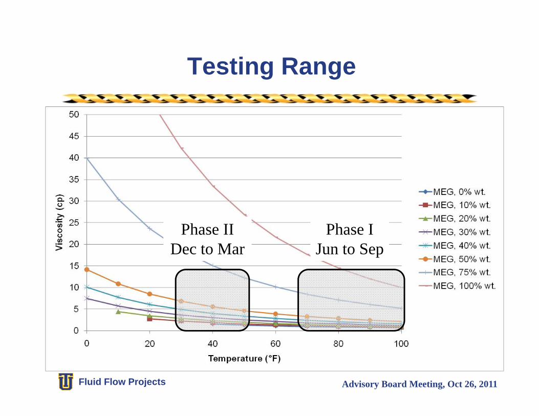
Testing Range
Phase IJun to Sep
Phase IIDec to Mar

Fluid Flow Projects Advisory Board Meeting, Oct 26, 2011
TEG Instead of MEG ?

Fluid Flow Projects Advisory Board Meeting, Oct 26, 2011
Future Activities
Project DefinitionPreliminary Discussions (Fall 2011)Test Matrix (January 2012)
Flow Loop Modification (Spring 2012) Data Acquisition (Starting Summer 2012) Model Comparison and Development
(Starting Spring 2013)

Fluid Flow Projects Advisory Board Meeting, Oct 26, 2011
Questions and Comments

Fluid Flow Projects
Advisory Board Meeting, October 26, 2011
Modeling of Droplet Entrainment in Co-current Annular Two-Phase
Flow: A New Approach
Abdel Al-Sarkhi

Fluid Flow Projects Advisory Board Meeting, October 26, 2011
Outline
Objective Introduction Entrainment Modeling Modeling of Maximum Entrainment Fraction,
FE, MAX Effect of Inclination Angle on FE, MAX Comparison With the Available Modes Conclusions & Recommendations

Fluid Flow Projects Advisory Board Meeting, October 26, 2011
Objective
Develop a Simple, Explicit and Accurate Entrainment Model With a Wide Range of Applicability The Model Should not Allow Negative
Entrainment Values or a Very Large Value That Exceeds the Maximum Possible Value

Fluid Flow Projects Advisory Board Meeting, October 26, 2011
Introduction
Annular Flow, Occurs in Many Industries and Processes Steam Generation and Power Plants Heating and Refrigeration Equipment Transportation of Crude Oil and Natural Gas
In Annular Flow, Entrainment Fraction Prediction is Important for the Estimation of Pressure Drop, Flow Rate, Liquid Holdup, Dry-out

Fluid Flow Projects
Entrainment Modeling
From the Onset of Entrainment to the Asymptotic Condition, the Complete Process can be Divided into Three Parts
Advisory Board Meeting, October 26, 2011
(Sawant et al. (2008))

Fluid Flow Projects
Entrainment Modeling …
The Trend Observed in Previous Figure has also been Seen in Many Other Processes Step Response of Electrical Systems
(Start-up of an Electric Motor (Ogata (2003))
Charging of a Capacitor in Resistance-Capacitance (RC) Circuit
Fouling of Heat Exchangers (Bott (1995))
Advisory Board Meeting, October 26, 2011

Fluid Flow Projects
Entrainment Modeling …
Rate of Fouling Deposition, Depends on the Type of Fouling Mechanism (Sedimentation, Crystallization, Organic Material Growth, etc.)
Rate of Fouling Removal, Depends on Both the Hardness and Adhesive Strength of the Deposit and the Shear Stress Due to the Flow Velocity, as Well as the Fill Configuration
Advisory Board Meeting, October 26, 2011
Various fouling models(Bott (1995))

Fluid Flow Projects
Entrainment Modeling …
The fouling model used for the asymptotic process is given below (Bott (1995)):
Where:
Advisory Board Meeting, October 26, 2011
))exp(1(*cff tRR τ−−=
Rf : the fouling resistance (common units are m2K/W)
t: time
Rf* : the asymptotic value of the fouling resistance
τc : the time constant, which is the time when fouling resistance reaches 63.2% of the asymptotic value

Fluid Flow Projects
Entrainment Modeling …
With the Analogy for the Entrainment Fraction, the Work of Sawant et al. (2008) Leads to the Following Model
Advisory Board Meeting, October 26, 2011
))WeWeexp((FF *SGSGmax,EE −−= 1
Where WeSG : Superficial Gas Weber Number FE,max : Asymptotic Value of Entrainment Fraction WeSG* : Analogous Time Constant, Dimensionless and the Weber Number When Entrainment Fraction is 63.2% of Its Asymptote
412 /
G
GLSGGSG
DvWe
−=
ρρρ
σρ

Fluid Flow Projects
Entrainment Modeling …
Model Validation Model Contains Two Constants i.e., FE,max and
WeSG* Two Constants are Currently Determined from
the Available Experimental Data Responses of Several Data Sets Representing
Different Operational Conditions, Pipe Diameters and Orientations are Tested
Advisory Board Meeting, October 26, 2011

Fluid Flow Projects
Model Validation
Model Comparison with Owen et al. (1985) Data in Vertical 0.0317 m Diameter Pipe (ReSL =3550)
Advisory Board Meeting, October 26, 2011
0.0
0.2
0.4
0.6
0.8
1.0
0 10000 20000 30000
F E
WeSG
Predicted
Measured

Fluid Flow Projects
0
0.1
0.2
0.3
0.4
0.5
0.6
0.7
0.8
0 10000 20000 30000
F E
WeSG
Measured
Predicted
Model Validation…
Model Comparison with Schadel and Hanratty (1989) Data from Vertical 0.042 m ID Pipe (ReSL= 2105)
Advisory Board Meeting, October 26, 2011

Fluid Flow Projects
0
0.2
0.4
0.6
0.8
1
0 10000 20000 30000
F E
WeSG
( )
450
950
1400
3000
5000
ReSL
Model Validation …
Comparison of Proposed Model with the Data of Sawant et al. (2008) in a Vertical 0.0094 m ID Pipe
Advisory Board Meeting, October 26, 2011

Fluid Flow Projects
0
0.2
0.4
0.6
0.8
1
0 500 1000 1500 2000 2500 3000 3500
F E
WeSG
Measured
Predicted
Model Validation …
Comparison of Proposed Model with the Data of Laurinat (1982) at ReSL = 6905 in a 0.0508 m ID Horizontal Pipe
Advisory Board Meeting, October 26, 2011

Fluid Flow Projects
Model Validation …
Interpretation of Previous Figures Proposed Model has a Strong and Clear
Potential to Predict Entrainment Fractions in 2-phase Vertical and Horizontal Annular Flow
Vertical Flow Data Match the Model Better Than Horizontal Flow Data
The Model is not Complex Only Information Required are the Two Constants
and VSG or WeSG
Advisory Board Meeting, October 26, 2011

Fluid Flow Projects
Modeling of FE,max
Few Attempts Available in Literature Pan and Hanratty (2002 a) At Low ReSL Values, FE,max Becomes
Negative as Reported By Al-sarkhi and Sarica (2011a)
Sawant et al. (2008) At Low ReSL, FE,max Goes to a Value Larger
Than Unity as Explained in Al-sarkhi and Sarica (2011b)
Advisory Board Meeting, October 26, 2011

Fluid Flow Projects
Modeling of FE,max …
Sawant et al. (2009) Attempted to Improve Sawant et al. (2008)
Advisory Board Meeting, October 26, 2011
SL
..μfSL
.μf
max,E Re)NRe(.N
F9505050 133013
1−− −+
−=
( ) 21 /
gf
ffN
ρσ
µσρ
µ
∆
=
f
SLfSL
DVRe
µρ
=
Viscosity Number
Superficial Liquid Reynolds Number

Fluid Flow Projects
Modeling of FE,max …
Sawant et al. (2009)
Two Issues Asymptotic Value is Always Around 0.8 Even
for Very Large (Unreasonably Large) Values of ReSL
Numerical Results are Invalid at Low Liquid Flow Rate of Annular Flows for
Advisory Board Meeting, October 26, 2011
SL
..μfSL
.μf
max,E Re)NRe(.N
F9505050 133013
1−− −+
−=
5.013Re −< ff N µ 013Re 50 <− − )N( .μfSLOR

Fluid Flow Projects
Variation of FE, max vs. ReSL (Vertical (V) and Horizontal (H) Pipes)
Advisory Board Meeting, October 26, 2011
Exp. Data: (Sawant et al. (2008); Owen et al. (1985), Schadel and Hanratty (1989); Deryabina et al. (1989), Magrini (2009); Assad et al. (1998); Mantilla (2008); Dallman (1978), Laurinat (1982) and Williams (1990))
0.0
0.1
0.2
0.3
0.4
0.5
0.6
0.7
0.8
0.9
1.0
0 2000 4000 6000 8000 10000 12000 14000 16000
F E,m
ax
ReSL
Experimental data (V)
Experimental data (H)

Fluid Flow Projects
Modeling of FE,max …
Following Closure Relationship is Proposed
Advisory Board Meeting, October 26, 2011
−−=
60
1.
*SL
SLlimmax,,Emax,E Re
ReexpFF
Where ReSL : Superficial Liquid Reynolds Number FE,max,lim: Asymptotic or Limiting Value of FE,max ReSL* : Analogous Time Constant in the Form of a Reynolds Number When Maximum Entrainment Fraction Reaches 63.2% of Its Limiting Value

Fluid Flow Projects
FE,max Closure Relationship
Two Constants Can be Determined Based on the
Experimental Data Shown in the Previous Figure
If All Thermo-physical Properties Remain Constant in the Reynolds Numbers, the Superficial Liquid Velocity, vSL, can be Used Instead of ReSL
Advisory Board Meeting, October 26, 2011

Fluid Flow Projects
FE,max Closure Relationship …
Limiting Value, FE,max,lim, would be Very Close to One Good Reasonable Value would be Just
One A Value of 1400 was Determined for
ReSL* (Reynolds Number When FE,max Reaches 63.2% of Its Limiting Value of One)
Advisory Board Meeting, October 26, 2011

Fluid Flow Projects
Validation of FE,max Closure Relationship
Advisory Board Meeting, October 26, 2011
-0.4
-0.2
0.0
0.2
0.4
0.6
0.8
1.0
0 2000 4000 6000 8000 10000 12000 14000
F E,m
ax
ReSL
Current Model
Experimental data (V)
Sawant et al. (2008)
Pan & Hanratty (2002)
Experimental Data (H)
Sawant et al. (2009)

Fluid Flow Projects
Validation of FE,max Closure Relationship …
Advisory Board Meeting, October 26, 2011
0
0.1
0.2
0.3
0.4
0.5
0.6
0.7
0.8
0.9
1
0.0 0.1 0.2 0.3 0.4 0.5 0.6 0.7 0.8 0.9 1.0
F E-m
ax, P
redi
ctio
n
FE-max, Measurement
Sawant (2008V)
Assad (1998V)
Owen (1985V)
Schadel(1988V)
Deryabina (1989V)
Mantilla (2008H)
Dallman (1978H)
Laurinat (1982H)
Williams(1990H)
+12%
-7%

Fluid Flow Projects
Validation of FE,max Closure Relationship …
Advisory Board Meeting, October 26, 2011
0
0.1
0.2
0.3
0.4
0.5
0.6
0.7
0.8
0.9
1
0.0 0.1 0.2 0.3 0.4 0.5 0.6 0.7 0.8 0.9 1.0
F E-m
ax, P
redi
ctio
n
FE-max, Measurement
Sawant (2008V)
Assad (1998V)
Owen (1985V)
Schadel(1988V)
Deryabina (1989V)
+10%
-7%

Fluid Flow Projects
Validation of FE,max Closure Relationship …
Advisory Board Meeting, October 26, 2011
0
0.1
0.2
0.3
0.4
0.5
0.6
0.7
0.8
0.9
1
0.0 0.1 0.2 0.3 0.4 0.5 0.6 0.7 0.8 0.9 1.0
F E-m
ax, P
redi
ctio
n
FE-max, Measurement
Mantilla (2008H)
Dallman (1978H)
Laurinat (1982H)
Williams(1990H)
+12%
-12%

Fluid Flow Projects
Comparison With Others
Pan and Hanratty (2002) Over Predicts While Sawant et al. (2008) Under Predicts
Sawant et al. (2009) Under Predicts at High ReSL and Over Predicts at Low ReSL
Sawant et al. (2008) and Pan and Hanratty (2002) Cannot Predict Maximum Entrainment Fraction at Very Low Liquid Reynolds Numbers (~ ReSL < 400)
Sawant et al. (2009) also has Similar Problems at Low ReSL
Proposed Equation Predicts the Experimental Data Very Well
Advisory Board Meeting, October 26, 2011

Fluid Flow Projects
Effect of Inclination Angle on FE, max
Advisory Board Meeting, October 26, 2011
0.0
0.1
0.2
0.3
0.4
0.5
0.6
0.7
0.8
0.9
1.0
0 1000 2000 3000 4000 5000 6000 7000 8000
F E,m
ax
ReSL
Current Model
Experimental data (V)
Experimental Data (H)
Magrini data (I)

Fluid Flow Projects
Conclusions
Entrainment Fraction was Successfully Modeled Using Experimental Data from Various Sources in the Literature
Only Information Required are the Superficial Liquid and Gas Velocities
Proposed Maximum Entrainment Fraction Prediction Equation Provide the Best Results Compared With Any Equation in the Literature
Advisory Board Meeting, October 26, 2011

Fluid Flow Projects
Recommendations
More Investigation is Needed for the Second Constant, WeSG*
Significant Experimental Work Still Need to Be Performed for Very High (FE,max > 0.85) and Low (FE,max < 0.5) Maximum Entrainment Fraction Region Using Air-water Two-phase Flow and Other Two-phase Fluid Flow Combinations
Advisory Board Meeting, October 26, 2011

Fluid Flow Projects
High Pressure Test Facility Construction Update
Eduardo Pereyra and Abdel Al-Sarkhi
Advisory Board Meeting, October 26, 2011

Fluid Flow Projects
Outline
Objectives Facility Basic Instrumentation Specialty Instrumentation Construction Schedule
Advisory Board Meeting, October 26, 2011

Fluid Flow Projects
Objectives
Scale-up of Small Diameter and Low Pressure Results to the Large Diameter and High Pressure Conditions
Advisory Board Meeting, October 26, 2011

Fluid Flow Projects
Facility
Advisory Board Meeting, October 26, 2011

Fluid Flow Projects
Facility …
Advisory Board Meeting, October 26, 2011

Fluid Flow Projects
Test Fluids
Test Fluid Nitrogen – Oil
Nitrogen is Selected as Gas Phase Oil Resembling Wet Gas Condensate is
Selected Isopar L
Advisory Board Meeting, October 26, 2011

Fluid Flow Projects
Basic Instrumentation
Advisory Board Meeting, October 26, 2011

Fluid Flow Projects
Specialty Instrumentation
Quick Closing Valves Visual Observation Capacitance Sensors Iso-kinetic Sampling Pitot Tube
Advisory Board Meeting, October 26, 2011

Fluid Flow Projects
PT1
PT2 TT2
TT1
Nitrogen
Quick Closing Valves
Advisory Board Meeting, October 26, 2011
Two and Three Phase Flow
QCV QCV
10 D
Two Wire Capacitance
Sensor
Two Wire Capacitance
Sensor For Oil-Water Level

Fluid Flow Projects
Steel Pipe
Visual Observation
Advisory Board Meeting, October 26, 2011
Custom Made High Pressure Sight Flow (Canty) Integral Light and Camera Disturbance Free Flow Cost $41,510
Acrylic Section
Steel Pipe
Pinside
Pchamber
Fuse

Fluid Flow Projects
Visual Observation …
Advisory Board Meeting, October 26, 2011
Custom Made High Pressure Sight Flow (Canty)
Side Window for High Speed Video Camera

Fluid Flow Projects
Capacitance Sensors
Advisory Board Meeting, October 26, 2011
10 D
Two Wires Waves Characteristics Length Celerity Frequency Amplitude

Fluid Flow Projects
Capacitance Sensors …
Advisory Board Meeting, October 26, 2011
10 D
Film Distribution Film thickness distribution

Fluid Flow Projects
Capacitance Sensors …
Advisory Board Meeting, October 26, 2011
Capacitance and Resistance Tomography Film Thickness Distribution Gas-Oil-Water (Water Continuous Only)

Fluid Flow Projects
Capacitance Sensors …
Advisory Board Meeting, October 26, 2011
Capacitance and Resistance Tomography
Industrial Tomography Systems (ITS) Cost = $ 236,870.00 Includes Software and Electronics

Fluid Flow Projects
Capacitance Sensors …
Advisory Board Meeting, October 26, 2011
Wire Mesh Sensor Film thickness distribution

Fluid Flow Projects
Capacitance Sensors …
Advisory Board Meeting, October 26, 2011
Wire Mesh Sensor GWT-TUD Cost = $ 85,645.00 (32 by 32 Wires) Include Software and Electronics Rental Option

Fluid Flow Projects
Iso-kinetic Sampling
Advisory Board Meeting, October 26, 2011
0.5 inch
1.5 inch
1.0 inch
0.5 inch 1.0 inch
1.5 inch
Multiple Probe Design

Fluid Flow Projects
Iso-kinetic Sampling …
Advisory Board Meeting, October 26, 2011
Flow
Gas Control Valve 1
2
4
Liquid Flow Meter
3
Collecting Flask
Supporting block
Swivel Joint
Gas Flow Meter

Fluid Flow Projects
Pitot Tube
Advisory Board Meeting, October 26, 2011
Previously Used Gas-Liquid Flow : Kawaji et al. (1987) and
Andreussi et al. (1986) Liquid-Liquid: Hamad and He (2010)
Static and Dynamic Lines Filled with Liquid
Omega High Accuracy Pitot Tube

Fluid Flow Projects
Pitot Tube …
Advisory Board Meeting, October 26, 2011

Fluid Flow Projects
Pitot Tube …
Advisory Board Meeting, October 26, 2011
Pipe wall
Welding
Support
High Pressure Industrial O-ring
0.28”
Threaded block
Tube, 0.5 inch OD

Fluid Flow Projects
Construction Schedule
Completion Dates HAZOP: January 2012 Electrical, Data Acquisition and Control
Systems: April 2012 Facility Commissioning: May 2012 Preliminary Test (Special Instrumentation
Installed): October 2012
Advisory Board Meeting, October 26, 2011

Fluid Flow Projects
Construction Schedule
HAZOP by COGNASCENTS 1. Process Hazards Analysis (PHA) Preparation
1. P&IDs and PFDs 2. Standard Operating Procedures (SOP) 3. Project Scope Documents
2. PHA Session
Advisory Board Meeting, October 26, 2011

Fluid Flow Projects
Construction Schedule …
HAZOP by COGNASCENTS 3. PHA Deliverables
1. HAZOP Worksheets with Recommendations 2. Supporting Documentation 3. PHA Session Sign-in Sheets 4. PHA Report 5. All Electronic Files Generated Specifically for
the University of Tulsa
Advisory Board Meeting, October 26, 2011

Fluid Flow Projects
Questions/Comments
Advisory Board Meeting, October 26, 2011

Fluid Flow Projects
Advisory Board Meeting, October 26, 2011
Liquid Loading of Gas Wells
Ge (Max) Yuan

Fluid Flow Projects Advisory Board Meeting, October 26, 2011
Comments from Last ABM
Dr. Taras Makogon, BP High Speed Camera to Get Gas Fraction
in Liquid Film Response: Limited Focus Depth of the Lens

Fluid Flow Projects Advisory Board Meeting, October 26, 2011
Comments from Last ABM …
Mr. Mack Shippen, Schlumberger Adding Tests in Well Deviation Range
of 0-15° Response: Limited Time
Studies to Be Continued with Another MS Student
Mechanism Investigated by Comparing Vertical and 15° Well Deviation Cases

Fluid Flow Projects Advisory Board Meeting, October 26, 2011
Comments from Last ABM …
Mr. Rob Sutton, Marathon Video Showing Liquid Flooding Near
Inlet Section Response: Accepted Observed in Some Cases Good Indicator of Liquid Loading in Some
Cases

Fluid Flow Projects Advisory Board Meeting, October 26, 2011
Outline
Objectives Introduction Experimental Program Experimental Results Conclusion Near Future Tasks

Fluid Flow Projects Advisory Board Meeting, October 26, 2011
Objectives
Explore Mechanisms Controlling Onset of Liquid Loading
Investigate Effect of Well Deviation on Liquid Loading

Fluid Flow Projects Advisory Board Meeting, October 26, 2011
Introduction
Gas Production Flow Regime Changes from Mist (a) to Annular (b) to Slug/Churn Flow (c) and Eventually Loads up (d).

Fluid Flow Projects Advisory Board Meeting, October 26, 2011
Introduction …
Critical Gas Flow Velocity Minimum Gas Velocity Required to Move Liquid
Droplets Upward Gas Rate at Flow Pattern Transition Gas Rate Required to Move Liquid Film Upward

Fluid Flow Projects Advisory Board Meeting, October 26, 2011
Experimental Program
Test Section Design
Test Fluids Gas – Air Water – Tap Water

Fluid Flow Projects Advisory Board Meeting, October 26, 2011
Experimental Program …
Test Ranges Superficial Gas Velocity: 10 to 30 m/s Superficial Liquid Velocity : 0.005, 0.01, 0.02, 0.05 and 0.1 m/s Well Deviation:
0º, 15º, 30º, 45º, 60º

Fluid Flow Projects Advisory Board Meeting, October 26, 2011
Instrumentation
Pressure and Temperature: PTs and DPs and TTs
Holdup: Quick Closing Valves Capacitance Sensor Wave Characteristics
High Speed Camera

Fluid Flow Projects Advisory Board Meeting, October 26, 2011
Capacitance Sensor
Type: Two Parallel Wires Range: 5 – 40 mm

Fluid Flow Projects Advisory Board Meeting, October 26, 2011
Capacitance Sensor …
Static Calibration
0
0.5
1
1.5
2
2.5
3
3.5
4
4.5
0 100 200 300 400 500 600 700 800 900 1000
Volta
ge O
utpu
ts (V
)
Water Volume of Injection (ml)
Probe 1
Probe 2
Fluid Temp.= 72 F

Fluid Flow Projects Advisory Board Meeting, October 26, 2011
Capacitance Sensor …
Sample Output for Annular Flow
0
0.5
1
1.5
2
2.5
3
3.5
4
4.5
5
1 4 7 10 13 16 19 22 25 28 31 34 37 40 43 46 49 52 55 58 61 64 67 70 73 76 79 82 85 88 91 94 97 100
Out
put S
igna
l (V)
Test Time (Scan Rate: 0.01s)
Probe 1
Probe 2

Fluid Flow Projects Advisory Board Meeting, October 26, 2011
Experimental Results
Criteria of Liquid Loading Flow Pattern (Videos) Differential Pressure Drop Liquid Holdup
Transient Phenomena

Fluid Flow Projects Advisory Board Meeting, October 26, 2011
Experimental Results …
Criteria of Liquid Loading Differential Pressure Drop (Vertical)
0
200
400
600
800
1000
1200
1400
0 5 10 15 20 25 30 35
Pres
sure
Gra
dien
t (Pa
/m)
VSG (m/s)
Vsl=0.01
Vsl=0.1

Fluid Flow Projects Advisory Board Meeting, October 26, 2011
Experimental Results …
Criteria of Liquid Loading Liquid Holdup (Vertical)
0.0000
0.0500
0.1000
0.1500
0.2000
0.2500
0 5 10 15 20 25 30 35
Liqu
id H
oldu
p
vSG (m/s)
Vsl=0.01
Vsl=0.1
Churn Flow Starts
Churn Flow Starts

Fluid Flow Projects Advisory Board Meeting, October 26, 2011
Experimental Results …
Criteria of Liquid Loading Differential Pressure Drop (15° Well Deviation)
0
200
400
600
800
1000
1200
1400
1600
0 5 10 15 20 25 30 35
Pres
sure
Gra
dien
t (Pa
/m)
VSG (m/s)
Vsl=0.01
Vsl=0.1

Fluid Flow Projects Advisory Board Meeting, October 26, 2011
Experimental Results …
Criteria of Liquid Loading Liquid Holdup (15° Well Deviation)
0.0000
0.0200
0.0400
0.0600
0.0800
0.1000
0.1200
0.1400
0.1600
0.1800
0 5 10 15 20 25 30 35
Liqu
id H
oldu
p
vSG (m/s)
Vsl=0.01
Vsl=0.1
Slug Flow Starts
Slug Flow Starts

Fluid Flow Projects Advisory Board Meeting, October 26, 2011
Flow Pattern
High Speed Videos (Vertical) Video 1
0
200
400
600
800
1000
1200
1400
0 5 10 15 20 25 30 35
Pres
sure
Gra
dien
t (Pa
/m)
VSG (m/s)
Vsl=0.01
Vsl=0.1
Video 1

Fluid Flow Projects Advisory Board Meeting, October 26, 2011
Flow Pattern …
High Speed Videos (Vertical) Video 2
0
200
400
600
800
1000
1200
1400
0 5 10 15 20 25 30 35
Pres
sure
Gra
dien
t (Pa
/m)
VSG (m/s)
Vsl=0.01
Vsl=0.1
Video 2

Fluid Flow Projects Advisory Board Meeting, October 26, 2011
Flow Pattern …
High Speed Videos (Vertical) Video 3
0
200
400
600
800
1000
1200
1400
0 5 10 15 20 25 30 35
Pres
sure
Gra
dien
t (Pa
/m)
VSG (m/s)
Vsl=0.01
Vsl=0.1
Video 3

Fluid Flow Projects Advisory Board Meeting, October 26, 2011
Flow Pattern …
High Speed Videos (Vertical) Video 4
0
200
400
600
800
1000
1200
1400
0 5 10 15 20 25 30 35
Pres
sure
Gra
dien
t (Pa
/m)
VSG (m/s)
Vsl=0.01
Vsl=0.1
Video 4

Fluid Flow Projects Advisory Board Meeting, October 26, 2011
Flow Pattern …
High Speed Videos (15° Well Deviation) Video 1
0
200
400
600
800
1000
1200
1400
1600
0 5 10 15 20 25 30 35
Pres
sure
Gra
dien
t (Pa
/m)
VSG (m/s)
Vsl=0.01
Vsl=0.1
Video 1

Fluid Flow Projects Advisory Board Meeting, October 26, 2011
Flow Pattern …
High Speed Videos (15° Well Deviation) Video 2
0
200
400
600
800
1000
1200
1400
1600
0 5 10 15 20 25 30 35
Pres
sure
Gra
dien
t (Pa
/m)
VSG (m/s)
Vsl=0.01
Vsl=0.1
Video 2

Fluid Flow Projects Advisory Board Meeting, October 26, 2011
Flow Pattern …
High Speed Videos (15° Well Deviation) Video 3
0
200
400
600
800
1000
1200
1400
1600
0 5 10 15 20 25 30 35
Pres
sure
Gra
dien
t (Pa
/m)
VSG (m/s)
Vsl=0.01
Vsl=0.1
Video 3

Fluid Flow Projects Advisory Board Meeting, October 26, 2011
Flow Pattern …
High Speed Videos (15° Well Deviation) Video 4
0
200
400
600
800
1000
1200
1400
1600
0 5 10 15 20 25 30 35
Pres
sure
Gra
dien
t (Pa
/m)
VSG (m/s)
Vsl=0.01
Vsl=0.1
Video 4

Fluid Flow Projects Advisory Board Meeting, October 26, 2011
Criteria of Liquid Loading
Vertical Wells Film Flow Reversal Flow Pattern Changes to Churn Flow
Deviated Wells Film at the Bottom Flows Downward Flow Pattern Changes to Intermittent
Flow

Fluid Flow Projects Advisory Board Meeting, October 26, 2011
Experimental Results …
0.001
0.01
0.1
1
10
1 10 100
v SL (
m/s
)
vSG (m/s)
Taitel Model
Barnea Model
TUFFP Model
No Loading
Loading
Onset of LiquidLoading
Test Results for Vertical Wells
Intermittent Flow Annular Flow

Fluid Flow Projects Advisory Board Meeting, October 26, 2011
Experimental Results …
0.001
0.01
0.1
1
10
1 10 100
v SL (
m/s
)
vSG (m/s)
Barnea Model
TUFFP Model
No Loading
Onset of LiquidLoading
Loading
Test Results for 15° from Vertical
Intermittent Flow Annular Flow

Fluid Flow Projects Advisory Board Meeting, October 26, 2011
Transient Phenomena
Liquid Accumulation in Pipe Section Waves Flowing Downward Wave Growth Liquid Flooding Near the Inlet
HD VIDEO

Fluid Flow Projects Advisory Board Meeting, October 26, 2011
Conclusion
For Vertical Wells Droplets Flowing Upward with Gas Core
Even Though Liquid Loading Occurs Controlled by Film Flow Reversal and
Droplet Deposition For Deviated Wells Wave Growth at Gas-Liquid Interphase
is Main Mechanism

Fluid Flow Projects Advisory Board Meeting, October 26, 2011
Near Future Tasks
Data Analysis November 2011 Model Comparison November 2011 Final Report December 2011

Fluid Flow Projects Advisory Board Meeting, October 26, 2011
Questions/Comments

Fluid Flow Projects
Advisory Board Meeting, Oct. 26, 2011
Liquid Loading of Gas Wells (Part 2)
Mujgan Guner

Fluid Flow Projects Advisory Board Meeting, Oct. 26, 2011
Outline
Objective Literature Review Proposed Study Instrumentation Near Future Tasks

Fluid Flow Projects Advisory Board Meeting, Oct. 26, 2011
Objective
Explore Mechanisms Controlling Onset of Liquid Loading in Vertical and Inclined Pipe Configurations

Fluid Flow Projects Advisory Board Meeting, Oct. 26, 2011
Literature Review
Liquid Loading in Annular Flow Zabaras et al. (1986)

Fluid Flow Projects Advisory Board Meeting, Oct. 26, 2011
Literature Review
Liquid Loading in Annular Flow Belt et al. (2007) Air and Water Flow 12.5 m Test Section and 2 in. ID Facility Main Motivation of the Study is to Relate
Liquid Loading to Film Reversal Rather Than Droplets Transportation Inclination Effect on Film Thickness

Fluid Flow Projects Advisory Board Meeting, Oct. 26, 2011
Literature Review …
Belt et al. (2007) … Mechanisms That Determine the Film
Distribution Around the Circumference and the Film Dynamics are Investigated Interfacial Friction Action of Roll Waves Secondary Flow On The Film Distribution

Fluid Flow Projects Advisory Board Meeting, Oct. 26, 2011
Proposed Study
Experimental Study of Film Reversal Mechanisms in Annular Flow Effects of Inclination Entrance Effects
Exploratory Experiments from Ge (Max)Yuan Will be Utilized to Generate the Test Matrix
Improved Instrumentation Will be Implemented

Fluid Flow Projects Advisory Board Meeting, Oct. 26, 2011
Proposed Study …
Parameters to Investigate Pressure Gradient Liquid Holdup Liquid Entrainment Film Thickness Wave Characteristics
Wave Celerity Wave Frequency Wave Amplitude

Fluid Flow Projects Advisory Board Meeting, Oct. 26, 2011
Instrumentation
Liquid Holdup Quick Closing Valves
Multiple QCVs Three Trapping Sections

Fluid Flow Projects Advisory Board Meeting, Oct. 26, 2011
Instrumentation …
Liquid Entrainment Isokinetic Sampling Device
Located in the Center of the Pipe

Fluid Flow Projects Advisory Board Meeting, Oct. 26, 2011
Instrumentation …
Wave Characteristics Capacitance Probes
Multiple Probes Around Pipe Periphery

Fluid Flow Projects Advisory Board Meeting, Oct. 26, 2011
Instrumentation …
Wave Characteristics Capacitance Probes Calibration Device
Motorized Linear Slide

Fluid Flow Projects Advisory Board Meeting, Oct. 26, 2011
Instrumentation …
Hydrogen Bubble Wire Observation of Velocity Distribution
Onset of Film Reversal
Wire - hydrogen bubbles by electrolysis of water
Wall
Flow

Fluid Flow Projects Advisory Board Meeting, Oct. 26, 2011
Instrumentation …
Boundary Layer Study Bussman et al.

Fluid Flow Projects Advisory Board Meeting, Oct. 26, 2011
Instrumentation …
Visual Observation Flow Pattern Evaluation Videos from the Bottom
of the Test Section to the Top by Utilizing Outdoor Surveillance Cameras
High Speed Camera Video Quality Will be Improved

Fluid Flow Projects Advisory Board Meeting, Oct. 26, 2011
Instrumentation …
Visual Observation Boroscope
Boroscope Will be Utilized to Observe the Film Flow Mechanism
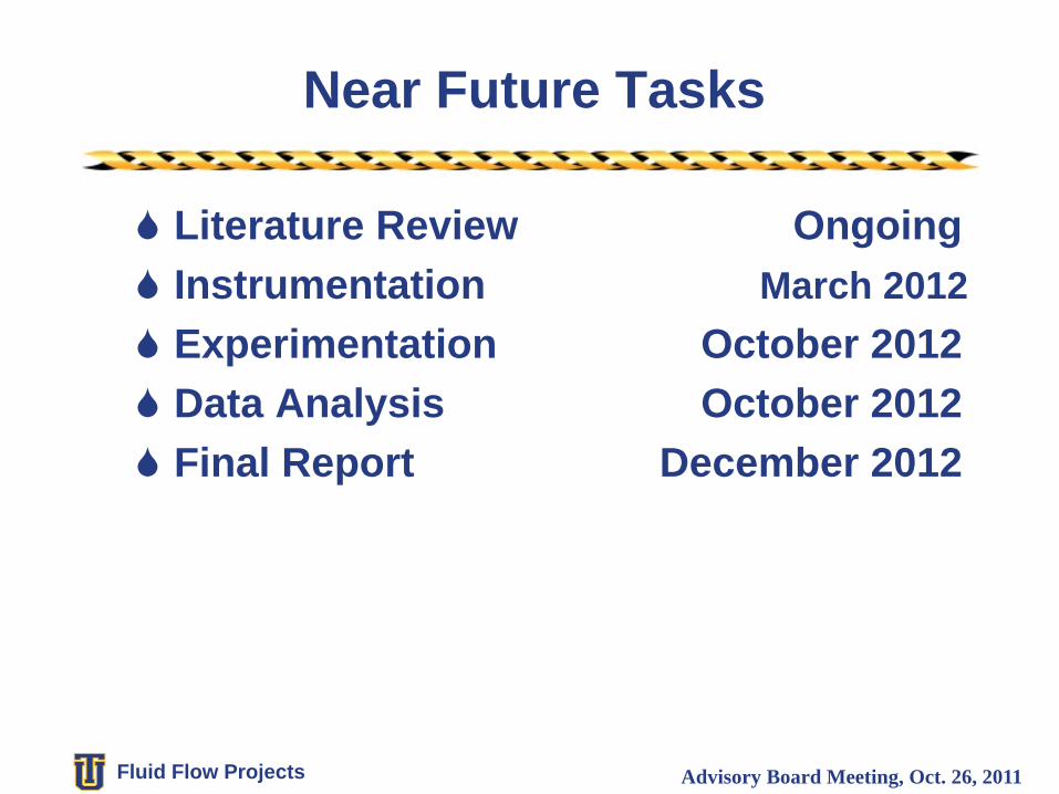
Fluid Flow Projects Advisory Board Meeting, Oct. 26, 2011
Near Future Tasks
Literature Review Ongoing Instrumentation March 2012 Experimentation October 2012 Data Analysis October 2012 Final Report December 2012

Fluid Flow Projects Advisory Board Meeting, Oct. 26, 2011
Questions & Comments

Fluid Flow Projects
Advisory Board Meeting, October 26, 2011
Simplified TransientTwo-Phase Flow Modeling
Jinho Choi

Fluid Flow Projects Advisory Board Meeting, October 26, 2011
Outline
Objectives Preliminary Simplified Transient
Model Activities SummarySimulator CompositionSimulator Validation
Future Work

Fluid Flow Projects Advisory Board Meeting, October 26, 2011
Objectives
Develop a Simplified Transient Model and Simulator for Gas-Liquid Two-Phase Flow in Pipelines
Test Model and Simulator Against Available Experimental Data

Fluid Flow Projects Advisory Board Meeting, October 26, 2011
Activities Summary
Development of a Simplified Isothermal Drift Flux Transient Model
Simulator Structure Design Preliminary Code (Explicit Solver) Preliminary Code Validation

Fluid Flow Projects Advisory Board Meeting, October 26, 2011
Preliminary Simplified Transient Model
Control Volume and Boundary Conditions

Fluid Flow Projects Advisory Board Meeting, October 26, 2011
Liquid ContinuityAssumption Constant Liquid Density
zuu
dtdH outSLinSLL
..
Gas Continuity
Preliminary Simplified Transient Model
Assumptions Isothermal Flow Constant Gas density
0.... outSGinSGoutSLinSL uuuu

Fluid Flow Projects Advisory Board Meeting, October 26, 2011
Drift Flux Closure Relationship
DSGSLL
SGG uuuC
Hu
u
)(1
2
2..
..
outSGinSGSG
outSLinSLSL
uuu
uuu
DoutSLinSLoutSGinSGL
outSGinSG uuuuuCHuu
)(212
1....
..
Preliminary Simplified Transient Model

Fluid Flow Projects Advisory Board Meeting, October 26, 2011
Equation Summary
inSGu . inSLu .,Input : outP,
inSGDinSLinSGLoutSG uuuuCHu .... 2)(2)1(
(1)
outSGinSLinSGoutSL uuuu ....
(2)
(3)
(4)
zuu
dtdH outSLinSLL
..
sin22
gduf
dzdp
MMM
M
Preliminary Simplified Transient Model

Fluid Flow Projects Advisory Board Meeting, October 26, 2011
Simulator Composition
Main
Modules
Pipeline Profile
Fluid Properties
Variables and Types
DPDL module
Read Data
File Out Initialization
Transition
Pipeline Profile
Simulation Condition
Operation Data
Length, Angle, Diameter, etc.
Max. time, Time step size, Flowing Fluid Condition(L-L, L-G)
Inlet Flow Rates, Separator Pressure
Densities & Viscosities & Surface Tension
fmGarcia2003
DPDLGarcia2003
C0v Function
Friction Factor
Pressure Gradient
Distribution Parameter, Now set as constant(ex, 1.0)
Ud Function Drift Velocity, Now set as Bendiksen(1984)’s eq.
Ug Function Drift Flux Model, Ug=C0v*Um+Ud
Holdup and Pressure Calculation

Fluid Flow Projects Advisory Board Meeting, October 26, 2011
Excel UI

Fluid Flow Projects Advisory Board Meeting, October 26, 2011
Simulator Flow Chart

Fluid Flow Projects Advisory Board Meeting, October 26, 2011
Simulator Validation
Experiments by Vigneron et al. (1995)Air and KeroseneHorizontal Pipe L=420 m, d=77.9 mmTwo Test Sections @ 61.4m, 395.7mTransient Caused By:Liquid flow rate changeGas flow rate changeLiquid blow outStart up

Fluid Flow Projects Advisory Board Meeting, October 26, 2011
Simulator Validation
Test# Initial(I)Final(F)
Flow Rate FlowPatten
Psep(Bar)Liquid
(m3/d)Gas
(Sm3/d)Liquid Flow Rate Changes
1A I 32.5 815 Slug 1.67F 168.4 815 Slug
1B I 8.4 400 SS 1.67F 31.8 400 SW
Gas Flow Rate Changes2A I 8.0 850 SS 1.67
F 8.0 4520 SW2B I 20.2 340 SS 1.67
F 20.2 2530 SWLiquid Blow Out
3A I 48.8 4825 SW 1.69F 0.0 4825 Single
3B I 204.0 5880 Slug 1.69F 0.0 5880 Single
Experiments by Vigneron et al. (1995)

Fluid Flow Projects Advisory Board Meeting, October 26, 2011
Simulator Validation
Test 1A – Liquid Flow Rate Change( QL=32.5(m3/d) 168.4(m3/d) @120s , QG=815(Sm3/d) )

Fluid Flow Projects Advisory Board Meeting, October 26, 2011
Simulator Validation
Test 1A – Liquid Flow Rate Change ( QL=32.5(m3/d) 168.4(m3/d) @120s , QG=815(Sm3/d) )

Fluid Flow Projects Advisory Board Meeting, October 26, 2011
Simulator Validation
Test 1B – Liquid Flow Rate Change ( QL=8.38(m3/d) 31.7(m3/d) @190s , QG=401(Sm3/d) )

Fluid Flow Projects Advisory Board Meeting, October 26, 2011
Simulator Validation
Test 1B – Liquid Flow Rate Change ( QL=8.38(m3/d) 31.7(m3/d) @190s , QG=401(Sm3/d) )

Fluid Flow Projects Advisory Board Meeting, October 26, 2011
Simulator Validation
Test 2A – Gas Flow Rate Change ( QL=8.00(m3/d) , QG=852.9(Sm3/d) 4519.4(Sm3/d) @120s )

Fluid Flow Projects Advisory Board Meeting, October 26, 2011
Simulator Validation
Test 2A – Gas Flow Rate Change ( QL=8.00(m3/d) , QG=852.9(Sm3/d) 4519.4(Sm3/d) @120s )

Fluid Flow Projects Advisory Board Meeting, October 26, 2011
Simulator Validation
Test 2B – Gas Flow Rate Change ( QL=20.14(m3/d) , QG=339.8(Sm3/d)2528.1(Sm3/d) @130s )

Fluid Flow Projects Advisory Board Meeting, October 26, 2011
Simulator Validation
Test 2B – Gas Flow Rate Change ( QL=20.14(m3/d) , QG=339.8(Sm3/d)2528.1(Sm3/d) @130s )

Fluid Flow Projects Advisory Board Meeting, October 26, 2011
Simulator Validation
Test 3A – Liquid Blow Out( QL=48.77(m3/d) 0(m3/d) @120s, QG=4528.2(Sm3/d) )

Fluid Flow Projects Advisory Board Meeting, October 26, 2011
Simulator Validation
Test 3A – Liquid Blow Out ( QL=48.77(m3/d) 0(m3/d) @120s, QG=4528.2(Sm3/d) )

Fluid Flow Projects Advisory Board Meeting, October 26, 2011
Simulator Validation
Test 3B – Liquid Blow Out( QL=204.12(m3/d) 0(m3/d) @95s, QG=5929.55(Sm3/d) )

Fluid Flow Projects Advisory Board Meeting, October 26, 2011
Simulator Validation
Test 3B – Liquid Blow Out ( QL=204.12(m3/d) 0(m3/d) @95s, QG=5929.55(Sm3/d) )

Fluid Flow Projects Advisory Board Meeting, October 26, 2011
Improvement of the Model
Vigneron et al. (1995)
UM=Usl + Usg
UG=CUM + UD
•UM : Mixture Velocity•Usl : Liquid Supeficial Velocity•Usg : Gas Superficial Velocity•UG : Gas Velocity•C : Distribution Parameter•UD : Drift Velocity

Fluid Flow Projects Advisory Board Meeting, October 26, 2011
Near Future Work
Properties Determination from Lookup Table Produced by PVTSim (Nov., 2011)
Improvement of Drift Flux Model (Nov., 2011) Distribution Parameter (Cv)
f(usl, usg, ρliquid, ρgas), or f(FrM, Res, β) , etc. Drift Velocity (Ud)
f(usg, ρliquid, ρgas, σ ) , or f(Nf, Eo, β) , etc. Liquid – Liquid (Oil-Water) Extension

Fluid Flow Projects Advisory Board Meeting, October 26, 2011
Near Future Work …
Application of Other Friction Factor Models (November 2011)
Implicit Scheme Implementation (November 2011)
Inclusion of Heat Transfer Model (December 2011)
Test of Model and Simulator (December 2011)
Final Report & Paper Work (December 2011)

Fluid Flow Projects Advisory Board Meeting, October 26, 2011
Questions and Comments

Fluid Flow Projects
Advisory Board Meeting, October 26, 2011
Unified Heat Transfer Modeling of Gas/Oil/Water Pipe Flow
Wei Zheng

Fluid Flow Projects Advisory Board Meeting, October 26, 2011
Outline
Comments from May ABM 2011 Objective Introduction Model Approaches Preliminary Result Research Plan Project Schedule

Fluid Flow Projects Advisory Board Meeting, October 26, 2011
Comments from May ABM 2011
Mack Shippen, SchlumbergerSuggested Kaminsky Model
Thomas Danielson, ConocoPhillipsSuggested to Consider Pressure
Effects Over the Pipe Temperature

Fluid Flow Projects Advisory Board Meeting, October 26, 2011
Comments from May ABM 2011
John Friedemann, GESuggest to Study J-Factor in Boiling
Water Brill, University of TulsaRecommend Paper “Comparison of 20
Two-Phase Heat Transfer Correlations with Seven Sets of Experimental Data, Including Flow Pattern and Tube Inclination Effects” from OSU

Fluid Flow Projects Advisory Board Meeting, October 26, 2011
Objective
Develop a Unified Heat Transfer Model for Gas/Oil/Water Three-Phase Flow in Pipes

Fluid Flow Projects Advisory Board Meeting, October 26, 2011
Introduction
Accurate Temperature Profile of Fluids Flowing in Pipes Crucial for Production System Design and Flow Assurance
No Mechanistic Heat Transfer Model for Gas/Oil/Water Pipe Flow Found

Fluid Flow Projects Advisory Board Meeting, October 26, 2011
Model Approaches
First ApproachGas/Pseudo-Liquid Phase
Second ApproachGas/Liquid Flow PatternOil/Water Flow Pattern

Fluid Flow Projects Advisory Board Meeting, October 26, 2011
First Approach
Combine Oil and Water as Single Phase Liquid
Liquid Physical Properties Estimated Based on Water Fraction
Calculation Using Unified Two-Phase Heat Transfer Model

Fluid Flow Projects Advisory Board Meeting, October 26, 2011
First Approach …
Liquid Physical PropertiesLiquid Viscosity: Brinkman CorrelationLiquid Surface Tension: Continuous
Phase Inversion Point: Brauner Model

Fluid Flow Projects Advisory Board Meeting, October 26, 2011
First Approach …
Zhang et al. (2005)Bubble FlowStratified/Annular FlowSlug Flow

Fluid Flow Projects Advisory Board Meeting, October 26, 2011
Second Approach
Flow Pattern and Hydrodynamics Predictions from Three-Phase Unified Hydrodynamic Model
Flow Pattern Oriented Heat Transfer Model

Fluid Flow Projects Advisory Board Meeting, October 26, 2011
Second Approach …
Hydrodynamic Model

Fluid Flow Projects Advisory Board Meeting, October 26, 2011
Second Approach …
Flow PatternBubble and Dispersed Bubble FlowOil & Water Fully Mixed
Annular Flow Oil & Water Fully Mixed
Stratified Flow Oil & Water Stratified

Fluid Flow Projects Advisory Board Meeting, October 26, 2011
Second Approach …
Slug FlowOil & Water Fully Mixed in Slug Body and
Film RegionOil & Water Stratified in Slug Body and
Film RegionOil & Water Stratified in Film Region and
Mixed in Slug Body

Fluid Flow Projects Advisory Board Meeting, October 26, 2011
Bubble and Dispersed Bubble Flow
Bubble and Dispersed Bubble Flow with Fully Mixed Oil and WaterPseudo Single-PhaseLiquid Properties: Oil & Water Mixture
)()(4
SGPGLSLPLLI
OMMM
vCvCdTTU
lT

Fluid Flow Projects Advisory Board Meeting, October 26, 2011
Annular Flow
Annular Flow with Fully Mixed Oil and Water in Film Liquid Properties: Oil & Water Mixture
)()()(
SGPGGSLPLL
OCCCOFFF
vCvCATTSUTTSU
lT

Fluid Flow Projects Advisory Board Meeting, October 26, 2011
Stratified Flow
Stratified Flow with Stratified Oil and WaterAssume
lT
lT
lT WOC
3CWoil
MTTTT

Fluid Flow Projects Advisory Board Meeting, October 26, 2011
Stratified Flow …
Heat Loss between Layers Neglected Heat Balance Equation
dlSqCATT CCPCSCCCC 21
PWSWWPOSOOPCSCC
OMI
CACACATTdU
lT
dlSqCATT OOPOSOOOO 21
dlSqCATT WWPWSWWWW 21

Fluid Flow Projects Advisory Board Meeting, October 26, 2011
Stratified Flow …
Overall Heat Transfer Coefficient
)( OMI
WWOOCC
TTdSqSqSqU
OMI
OWWW
OMI
OOilOO
OMI
OCCC
TTdTTSU
TTdTTSU
TTdTTSUU

Fluid Flow Projects Advisory Board Meeting, October 26, 2011
Stratified Flow …
Overall Heat Transfer Coefficient
)( OOilCC
OO
POSOO
PCSCCOC TT
SUSU
CCTT
)( OWCC
WW
PWSWW
PCSCCOC TT
SUSU
CCTT
CC
OO
POSOO
PCSCC
SUSU
CCB
1
CC
WW
PWSWW
PCSCC
SUSU
CCB
2
333OCOWOoil
OMTTTTTTTT

Fluid Flow Projects Advisory Board Meeting, October 26, 2011
Stratified Flow …
Overall Heat Transfer Coefficient
331
3331
331
31
31 2
1
21
2
1
21
BBBd
SUB
BBd
SU
BBd
SUU
I
WW
I
OO
I
CC
31
31
31
21
BBTTTT
OC
OM
331
32
1
2 BBB
TTTT
OW
OM
331
31
2
1 BBB
TTTT
OOil
OM

Fluid Flow Projects Advisory Board Meeting, October 26, 2011
Slug Flow
General Calculation
TU
t
S
t
F
UA l
dtTdtTT
SF
00
SF
SF
elal
elal
sF
OUA
eee
aeef
abl
efl
ab
TTlT
11111

Fluid Flow Projects Advisory Board Meeting, October 26, 2011
Slug Flow …
Slug Flow with Oil & Water Fully Mixed in Slug Body and Film RegionSame as First Approach

Fluid Flow Projects Advisory Board Meeting, October 26, 2011
Slug Flow …
Slug Flow with Stratified Oil and Water

Fluid Flow Projects Advisory Board Meeting, October 26, 2011
Slug Flow with Stratified Oil and Water
Film Region
WFOWFWFPWWWFWFU
UPWWWFWFT
W
T
STTUCAHlTCHA
tT
1
WFOOFOFPOOOFOFU
UPOOOFOFT
Oil
T
STTUCAHlTCHA
tT
1
CFOCFCFPCCOFWFCFU
UPCCOFWFCFT
C
T
STTUCAHHlTCHHA
tT
111

Fluid Flow Projects Advisory Board Meeting, October 26, 2011
Slug Flow with Stratified Oil and Water …
Film RegionAssume
tT
tT
tT
tT FCOilW
OFUF
T
TTaTbt
T
1
PCCOFWFCFTPOOOFOFTPWWWFWFTU
PCCOFWFCFPOOOFOFPWWWFWF
CHHCHCHlCHHCHCHb
1
1
PCCOFWFCFTPOOOFOFTPWWWFWFT
CFCFOFOFWFWF
CHHCHCHASUSUSUa
1

Fluid Flow Projects Advisory Board Meeting, October 26, 2011
Slug Flow with Stratified Oil and Water …
Slug Body
OSOOSOSPOOOSWSOSU
UPOOOSWSOST
OS
T
STTUCAHlTCHA
tT
11111
WSOWSWSPWWWSWSWSU
UPWWWSWSWST
WS
T
STTUCAHlTCHA
tT
111

Fluid Flow Projects Advisory Board Meeting, October 26, 2011
Slug Flow with Stratified Oil and Water …
Slug BodyAssume
tT
tT
tT SOSWS
OSUS
T
TTeTft
T
1
PWWWSWSWSTPOOOSWSOSTU
PWWWSWSWSPOOOSWSOS
CHCHlCHCHf
111111
PWWWSWSWSTPOOOSWSOST
WSWSOSOS
CHCHASUSUe
111

Fluid Flow Projects Advisory Board Meeting, October 26, 2011
Slug Flow with Stratified Oil and Water …
General Calculation
TU
t
S
t
F
UA l
dtTdtTT
SF
00
SF
SF
elal
elal
sF
OUA
eee
aeef
abl
efl
ab
TTlT
11111

Fluid Flow Projects Advisory Board Meeting, October 26, 2011
Slug Flow
Slug Flow with Stratified Oil and Water in Film Region

Fluid Flow Projects Advisory Board Meeting, October 26, 2011
Slug Flow with Stratified Oil and Water in Film Region
Film Region
OFUF
T
TTaTbt
T
1
PCCOFWFCFTPOOOFOFTPWWWFWFTU
PCCOFWFCFPOOOFOFPWWWFWF
CHHCHCHlCHHCHCHb
1
1
PCCOFWFCFTPOOOFOFTPWWWFWFT
CFCFOFOFWFWF
CHHCHCHASUSUSUa
1

Fluid Flow Projects Advisory Board Meeting, October 26, 2011
Slug Flow with Stratified Oil and Water in Film Region …
Slug Body
OSUS
T
TTeTft
T
1
MTU
M
lf
MTLSPLL
IS
AHCdUe

Fluid Flow Projects Advisory Board Meeting, October 26, 2011
Slug Flow with Stratified Oil and Water in Film Region …
General Calculation
TU
t
S
t
F
UA l
dtTdtTT
SF
00
SF
SF
elal
elal
sF
OUA
eee
aeef
abl
efl
ab
TTlT
11111

Fluid Flow Projects Advisory Board Meeting, October 26, 2011
Preliminary Result
First Approach (Software Inputs)Fluid Properties
Superficial Oil Velocity m/s 0.5Superficial Water Velocity m/s 0.5Superficial Gas Velocity m/s 4
Oil Density kg/m³ 1200Water Density kg/m³ 1200Gas Density kg/m³ 1.2047Oil Viscosity Pa.s 0.001
Water Viscosity Pa.s 0.001Gas Viscosity Pa.s 0.0000181
Liquid Viscosity at Wall cp 254OW Surface Tension N/m 0.076OG Surface Tension N/m 0.076GW Surface Tension N/m 0.076
Inlet Pressure psia 1001Inlet Temperature F° 69

Fluid Flow Projects Advisory Board Meeting, October 26, 2011
Preliminary Result …
First Approach (Software Inputs)
Pipe ProfileTotal Pipe Number - 1 2 3
Inner Diameter in 6 6 6Outer Diameter in 6.4 6.7 6.7
Length m 1000 2000 4000Number of Section - 30 20 40
Elevation m 500 800 200Absolute
Roughness mm 0.004 0.004 0.04
Heat Transfer InputOil Heat Capacity J/(Kg.C°) 1980
Water Heat Capacity J/(Kg.C°) 2210Gas Heat Capacity J/(Kg.C°) 2344.6
Oil Thermal Conductivity W/(m.C°) 0.2Water Thermal Conductivity W/(m.C°) 0.1609Gas Thermal Conductivity W/(m.C°) 0.0403Pipe Thermal Conductivity W/(m.C°) 16.29
Initial Ambient Temperature F° 80Geothermal Temperature Gradient - -0.02Outside Heat Transfer Coefficient W/(m².C°) 2396.28

Fluid Flow Projects Advisory Board Meeting, October 26, 2011
Preliminary Result …
First Approach (Software Outputs)

Fluid Flow Projects Advisory Board Meeting, October 26, 2011
Verification
Gas/Liquid Heat Transfer Model
Fluid PropertiesSuperficial Liquid Velocity m/s 1Superficial Gas Velocity m/s 4
Liquid Density kg/m³ 1200Gas Density kg/m³ 1.2047
Liquid Viscosity Pa.s 0.001Gas Viscosity Pa.s 0.0000181
Liquid Viscosity at Wall cp 254Surface Tension N/m 0.076
Inlet Pressure psia 1001Inlet Temperature F° 69
Fluid PropertiesSuperficial Oil Velocity m/s 0.5
Superficial Water Velocity m/s 0.5Superficial Gas Velocity m/s 4
Oil Density kg/m³ 1200Water Density kg/m³ 1200Gas Density kg/m³ 1.2047Oil Viscosity Pa.s 0.001
Water Viscosity Pa.s 0.001Gas Viscosity Pa.s 0.0000181
Liquid Viscosity at Wall cp 254OW Surface Tension N/m 0.076OG Surface Tension N/m 0.076GW Surface Tension N/m 0.076
Inlet Pressure psia 1001Inlet Temperature F° 69

Fluid Flow Projects Advisory Board Meeting, October 26, 2011
Verification
Gas/Liquid Heat Transfer Model
Pipe ProfileTotal Pipe Number - 1 2 3
Inner Diameter in 6 6 6Outer Diameter in 6.4 6.7 6.7
Length m 1000 2000 4000Number of Section - 30 20 40
Elevation m 500 800 200Absolute
Roughness mm 0.004 0.004 0.04
Heat Transfer InputOil Heat Capacity J/(Kg.C°) 1980
Water Heat Capacity J/(Kg.C°) 2210Gas Heat Capacity J/(Kg.C°) 2344.6
Oil Thermal Conductivity W/(m.C°) 0.2Water Thermal Conductivity W/(m.C°) 0.1609Gas Thermal Conductivity W/(m.C°) 0.0403Pipe Thermal Conductivity W/(m.C°) 16.29
Initial Ambient Temperature F° 80Geothermal Temperature Gradient - -0.02Outside Heat Transfer Coefficient W/(m².C°) 2396.28

Fluid Flow Projects Advisory Board Meeting, October 26, 2011
Verification
Results Comparison

Fluid Flow Projects Advisory Board Meeting, October 26, 2011
Research Plan
Model–1st Approach August 2011Model– 2nd Approach February 2012Model Evaluation March 2012Software Implementation May 2012

Fluid Flow Projects Advisory Board Meeting, October 26, 2011
Project Schedule
Literature Review CompleteModel–1st Approach CompleteModel– 2nd Approach CompleteModel Evaluation OngoingSoftware Implementation OngoingFinal Report May 2012

Fluid Flow Projects Advisory Board Meeting, October 26, 2011
Questions/Comments

Fluid Flow Projects
Advisory Board Meeting, October 26, 2011
Business Report
Cem Sarica

Fluid Flow Projects Advisory Board Meeting, October 26, 2011
Membership and Collaboration Status
Current Membership StatusMembership Steady at 16 15 Industrial and MMS
Efforts Continue to Increase TUFFP MembershipSaudi Aramco and Statoil are Expected
to Rejoin for 2012 Collaboration with Seoul National
University ContinuesVisiting Research Scholars and
Financial Contribution

Fluid Flow Projects Advisory Board Meeting, October 26, 2011
Publications and Papers
Alsarkhi, A. and Sarica, C.: Comment on: "Correlation of Entrainment for Annular Flow in Horizontal Pipes", by Pan, L., and Hanratty, T.J., Int. J. Multiphase Flow, 28(3), pp. 385-408. (2002)" International Journal of Multiphase Flow, pp.535-536, 37/5, June 2011.
Alsarkhi, A. and Sarica, C.: Comment on: “Droplet entrainment correlation in vertical upward co-current annular two-phase flow”, by Sawant, P., Ishii, M., Mori, M., Nuclear Engineering and Design 238 1342–1352 (2008) Nuclear Engineering and Design. pp. 3357-3358, 241/8, August 2011.
Zhang, H. Q., and Sarica, C.: “A Model for Wetted Wall Fraction and Gravity Center of Liquid Film in Gas-Liquid Pipe Flow,” Society of Petroleum Engineers Journal September 2011.
Al-Safran, E., Gokcal, B., and Sarica, C.: “High Viscosity Liquid Effect on Two-Phase Slug Length in Horizontal Pipes,” Presented at 15th International Conference Multiphase Production 11, Cannes, France, June 15-17, 2011.

Fluid Flow Projects Advisory Board Meeting, October 26, 2011
Next Advisory Board Meetings
Tentative Schedule April 25, 2012
TUHOP MeetingTUFFP WorkshopFacility Tour TUHOP/TUHFP/TUFFP Reception
April 26, 2012TUFFP MeetingTUFFP/TUPDP Dinner
April 27, 2012 TUPDP Meeting
Venue is The University of Tulsa

Fluid Flow Projects Advisory Board Meeting, October 26, 2011
Financial Report
Year 2011 UpdateTUFFP Industrial Account TUFFP BSEE Account
Year 2012 ProposedTUFFP Industrial Account TUFFP BSEE Account

2011 Industrial Account SummaryAnticipated Reserve Fund Balance on January 1, 2011 ($29,760)Income for 2011
2011 Anticipated Membership Fees (15 @ $55,000 - excludes MMS) 825,000 Facility Utilization Fee (SNU) 55,000 Facility Utilization Fee (Foam Project) 60,000
Total Budget 910,240$ Projected Budget/Expenditures for 2011
Projected Budget 11/3/10
Revised Budget
April 2011
2011 Expenditures
10/10/11
Revised Budget 10/10/11
90101 - 90103 Faculty Salaries 38,481.88 38,481.88 13,896.26 27,918.00 90600 - 90609 Professional Salaries 71,906.23 51,656.23 32,193.70 44,588.00 90700 - 90703 Staff Salaries 28,306.09 31,289.67 20,310.56 30,858.00
90800 Part-time/Temporary 24,000.00 19,272.67 20,339.35 91000 Student Salaries - Monthly 43,950.00 43,950.00 34,000.00 43,950.00 91100 Student Salaries - Hourly 15,000.00 15,000.00 7,195.78 10,000.00 91800 Fringe Benefits (35 %) 48,542.97 42,500.00 23,487.31 36,177.00 92102 Fringe Benefits (Students) 3,516.00 2,460.00 3,516.00 81801 Tuition & Student Fees - 10,492.00 19,223.00 81806 Fellowship 1,125.00 1,125.00 93100 General Supplies 3,000.00 3,000.00 2,786.50 3,500.00 93101 Research Supplies 100,000.00 100,000.00 92,236.98 120,000.00 93102 Copier/Printer Supplies 500.00 500.00 75.08 300.00 93104 Computer Software 4,000.00 4,000.00 2,623.50 3,000.00 93106 Office Supplies 2,000.00 2,000.00 656.91 1,200.00 93150 Computers ($1000 - $4999) 1,423.23 1,423.23 93200 Postage and Shipping 500.00 500.00 326.28 500.00 93300 Printing and Duplicating 2,000.00 2,000.00 2,202.74 3,000.00 93400 Telecommunications 3,000.00 3,000.00 1,500.00 2,500.00 93500 Membership 1,000.00 1,000.00 133.67 500.00 93601 Travel - Domestic 10,000.00 10,000.00 3,030.52 9,000.00 93602 Travel - Foreign 10,000.00 10,000.00 8,609.55 9,000.00 93700 Entertainment 10,000.00 16,000.00 11,714.95 16,000.00 94813 Outside Services 20,000.00 40,000.00 17,977.22 30,000.00 95103 Equipment Rental 11,518.05 15,000.00 95200 F&A (52.4%) 103,565.56 107,094.00 57,826.90 95,710.00 98901 Employee Recruiting 3,000.00 3,000.00 201.52 250.00 99001 Equipment 250,000.00 250,000.00 112,773.20 150,000.0099002 Computers 8,000.00 8,000.00 6,155.51 6,155.51 99300 Bank Charges 40.00 40.00 32.00 40.00
Total Anticipated Expenditures 776,792.73 810,527.78 498,237.59 704,773.09 Anticipated Reserve as of 12/31/11 205,466.65
(Prepared October 10, 2011)

Fluid Flow Projects Advisory Board Meeting, October 26, 2011
2011 BSEE Account Summary
Reserve Balance as of 12/31/10 12,781.55 2011 Budget 48,000.00
Total Budget 60,781.55
Projected Budget/Expenditures for 2011
Budget
Revised Budget
April 20112011
Expenditures91000 Students - Monthly 29,000.00 36,425.00 35,700.00 91202 Student Fringe Benefits 2,320.00 2,914.00 2,856.00 95200 F&A 15,196.00 20,252.00 19,849.20
Total Anticipated Expenditures as of 12/31/11 46,516.00 59,591.00 58,405.20
Total Anticipated Reserve Fund Balance as of 12/31/11 2,376.35
(Prepared October 11, 2011)

2012 Proposed Industrial Account Budget
Anticipated Reserve Fund Balance on January 1, 2012 $205,466.65Income for 2012
2012 Anticipated Membership Fees (15 @ $55,000 - excludes MMS) $825,000.00Facility Utilization Fee (SNU) $55,000.00
Total Income $1,085,466.652009 Anticipated Expenditures 90101-90103 Faculty Salaries 30,712.4790600-90609 Professional Salaries 117,198.2290700-90703 Staff Salaries 34,597.60
91000 Graduate Students 54,050.0091100 Undergraduate Students 15,000.0091800 Fringe Benefits (35%) 63,877.9093100 General Supplies 3,000.0093101 Research Supplies 120,000.0093102 Copier/Printer Supplies 750.0093104 Computer Software 4,000.0093106 Office Supplies 2,000.0093200 Postage/Shipping 500.0093300 Printing/Duplicating 3,000.0093400 Telecommunications 2,500.0093500 Memberships/Subscriptions 1,000.0093601 Travel - Domestic 10,000.0093602 Travel - Foreign 10,000.0093700 Entertainment (Advisory Board Meetings) 16,000.0081801 Tuition/Student Fees 18,686.1094803 Consultants 0.0094813 Outside Services 20,000.0095200 Indirect Costs (52.4%) 144,392.5598901 Employee Recruiting 3,000.0099001 Equipment 300,000.0099002 Computers 8,000.0099300 Bank Charges 40.00
Total Expenditures $982,304.84Anticipated Reserve Fund Balance on December 31, 2012 $103,161.81
(Prepared October 11, 2011)

Fluid Flow Projects Advisory Board Meeting, October 26, 2011
2012 Proposed BSEE Account Budget
Account Balance - January 1, 2011 $2,376.35Income for 2012
2012 Membership Fee $48,000.00
Remaining Balance $50,376.35
2009 Anticipated Expenditures Projected Budget90101-90103 Faculty Salaries - 90600-90609 Professional Salaries - 90700-90703 Staff Salaries -
91000 Graduate Students 28,700.0092102 Student Fringe Benefits (8%) 2,296.0095200 Indirect Costs (55.6%) 15,957.20
Total Expenditures $46,953.20
Anticipated Reserve Fund Balance on December 31, 2012 $3,423.15
(Prepared October 11, 2011)

Fluid Flow Projects Advisory Board Meeting, October 26, 2011
History – MembershipO
il Pr
ice
$
0
20
40
60
80
100
120
140
160
0
5
10
15
20
25
30
35
40
45
50
1973 1975 1977 1979 1981 1983 1985 1987 1989 1991 1993 1995 1997 1999 2001 2003 2005 2007 2009 2011 2013
OIl
Pric
e, $
Num
ber o
f Mem
bers
Year
Members Oil Price

Fluid Flow Projects Advisory Board Meeting, October 26, 2011
History – Membership Fees

Fluid Flow Projects Advisory Board Meeting, October 26, 2011
History - Expenditures

Fluid Flow Projects Advisory Board Meeting, October 26, 2011
Membership Fees
2011 Membership DuesAll PaidThank You

Tulsa University Fluid Flow Projects Seventy Seventh Semi-Annual Advisory Board Meeting Agenda
Wednesday, October 26, 2011 8:00 a.m. Breakfast – Allen Chapman Activity Center – Gallery 8:30 Introductory Remarks Cem Sarica 8:45 TUFFP Progress Reports Executive Summary Cem Sarica Effect of Pipe Inclination on Flow Characteristics of High Viscosity
Oil-Gas Two-Phase Flow Benin Jeyachandra
10:15 Coffee Break 10:30 TUFFP Progress Reports Downward Two-Phase Stratified Flow for Highly Viscous Oils Rosmer Brito Effect of Medium Oil Viscosity on Two-Phase Oil-Gas Flow
Behavior in Horizontal Pipes Rosmer Brito
Characterization of High Viscosity Slug Flow in Horizontal Pipes Eissa Alsafran 12:00 p.m. Lunch – Allen Chapman Activity Center - Chouteau C 1:15 TUFFP Progress Reports Low Liquid Loading Gas-Oil-Water Flow Kiran Gawas Effects of MEG on Multiphase Flow Behavior Hamidreza Karami Modeling of Droplet Entrainment in Co-current Annular Two-Phase
Flow: A New Approach Abdel Al-Sarkhi
High Pressure Test Facility Construction Update Eduardo Pereyra/
Abdel Al-Sarkhi 3:00 Coffee Break 3:15 TUFFP Progress Reports Low Liquid Loading of Gas Wells (Part 1) Ge (Max) Yuan Low Liquid Loading of Gas Wells (Part 2) Mujgan Guner Simplified Transient Two-Phase Modeling Jinho Choi Unified Heat Transfer Modeling of Gas-Oil-Water Pipe Flow Wei Zheng 4:25 TUFFP Business Report Cem Sarica 4:40 Open Discussion Cem Sarica 5:10 Adjourn

5:30 TUFFP/TUPDP Reception - Allen Chapman Activity Center - Atrium