Fluid Couplings FLUDEX Series - Talaweb.comxspace.talaweb.com/siemens-daihongphat/home/Khop noi...
50
Siemens MD 10.1 · 2008 13 13/2 Overview 13/2 Benefits 13/2 Application 13/2 Design 13/5 Function 13/6 Technical data 13/7 Configuration 13/7 Selection of coupling 13/7 Selection of series 13/10 Selection of type 13/11 Selection of size 13/12 FLUDEX coupling as aid to starting IEC motors 13/12 Selection and ordering data 13/12 Speed n = 1500 rpm 13/14 Speed n = 3000 rpm 13/16 Type FAO 13/16 Selection and ordering data 13/17 Type FAR with attached V-belt pulley 13/17 Selection and ordering data 13/18 Type FAD 13/18 Selection and ordering data 13/19 Type FAE 13/19 Selection and ordering data 13/20 Type FAM 13/20 Selection and ordering data 13/21 Type FADB 13/21 Selection and ordering data 13/22 Type FADS SB 13/22 Selection and ordering data 13/23 Type FADS HB 13/23 Selection and ordering data 13/24 Oil filling quantities for FA series 13/24 Selection and ordering data 13/26 Types FGO/FVO 13/26 Selection and ordering data 13/27 Types FGD/FVD 13/27 Selection and ordering data 13/28 Types FGE/FVE 13/28 Selection and ordering data 13/29 Types FGM/FVM 13/29 Selection and ordering data 13/30 Oil filling quantities for FG/FV series 13/30 Selection and ordering data 13/32 Type FNO 13/32 Selection and ordering data 13/33 Type FNA 13/33 Selection and ordering data 13/34 Type FND 13/34 Selection and ordering data 13/35 Type FNDB 13/35 Selection and ordering data 13/37 Type FNDS SB 13/37 Selection and ordering data 13/38 Type FNDS HB 13/38 Selection and ordering data 13/39 Oil filling quantities for FN series 13/39 Selection and ordering data 13/41 Spare parts 13/41 Selection and ordering data 13/45 Mass moments of inertia and maximum oil filling quantities 13/45 Technical data 13/48 Special types 13/48 Selection and ordering data 13/50 Form Technical specifications for the selection of type and size for FLUDEX fluid couplings Fluid Couplings FLUDEX Series © Siemens AG 2008
Transcript of Fluid Couplings FLUDEX Series - Talaweb.comxspace.talaweb.com/siemens-daihongphat/home/Khop noi...

Siemens MD 10.1 · 2008
1313/2 Overview
13/2 Benefits
13/2 Application
13/2 Design
13/5 Function
13/6 Technical data
13/7 Configuration
13/7 Selection of coupling
13/7 Selection of series
13/10 Selection of type
13/11 Selection of size
13/12 FLUDEX coupling as aid to
starting IEC motors
13/12 Selection and ordering data
13/12 Speed n = 1500 rpm
13/14 Speed n = 3000 rpm
13/16 Type FAO
13/16 Selection and ordering data
13/17 Type FAR with attached V-belt pulley
13/17 Selection and ordering data
13/18 Type FAD
13/18 Selection and ordering data
13/19 Type FAE
13/19 Selection and ordering data
13/20 Type FAM
13/20 Selection and ordering data
13/21 Type FADB
13/21 Selection and ordering data
13/22 Type FADS SB
13/22 Selection and ordering data
13/23 Type FADS HB
13/23 Selection and ordering data
13/24 Oil filling quantities for
FA series
13/24 Selection and ordering data
13/26 Types FGO/FVO
13/26 Selection and ordering data
13/27 Types FGD/FVD
13/27 Selection and ordering data
13/28 Types FGE/FVE
13/28 Selection and ordering data
13/29 Types FGM/FVM
13/29 Selection and ordering data
13/30 Oil filling quantities for
FG/FV series
13/30 Selection and ordering data
13/32 Type FNO
13/32 Selection and ordering data
13/33 Type FNA
13/33 Selection and ordering data
13/34 Type FND
13/34 Selection and ordering data
13/35 Type FNDB
13/35 Selection and ordering data
13/37 Type FNDS SB
13/37 Selection and ordering data
13/38 Type FNDS HB
13/38 Selection and ordering data
13/39 Oil filling quantities for FN series
13/39 Selection and ordering data
13/41 Spare parts
13/41 Selection and ordering data
13/45 Mass moments of inertia and
maximum oil filling quantities
13/45 Technical data
13/48 Special types
13/48 Selection and ordering data
13/50 Form
Technical specifications for the
selection of type and size for
FLUDEX fluid couplings
Fluid Couplings FLUDEX Series
© Siemens AG 2008
FLENDER Standard CouplingsFluid Couplings - FLUDEX Series
General information
13/2 Siemens MD 10.1 · 2008
13
nOverview
Coupling suitable for potentially explosive environments. Complies with Directive 94/9/EC for:
II 2 Gc T3 D160 °C II B–30 °C % Ta %+50 °C
I M2
nBenefits
FLUDEX couplings are hydrodynamic fluid couplings which op-erate on the Föttinger principle. The coupling parts on the input and output sides are not mechanically connected to each other. Output is transmitted via the oil filling which rotates in the cou-pling and is conducted over radially arranged blades.
FLUDEX couplings limit starting and maximum torque in the drive train and, through the property of rotational slip, serve as an aid to starting the motor, as overload protection in the event of fault and for isolating torsional vibration.
When large masses are started up, the drive train is accelerated only at the torque determined by the coupling characteristic. The starting operation is spread over time, the driven machine started softly and smoothly.
In the case of special operating conditions, such as overload or blocking of the driven machine, the effect of the motor mass is eliminated and the maximum torque load of the drive train limited by the FLUDEX coupling.
The coupling then acts as a load-holding safety clutch until the drive is shut off by the motor control or coupling monitoring sys-tem.
The FLUDEX coupling further acts as a means of decoupling during torsional vibration excitation. Torsional vibration excita-tion with a frequency of >5 Hz is virtually absorbed by the cou-pling.
To compensate for shaft misalignment, the FLUDEX coupling is combined with a displacement coupling e.g. of the N-EUPEX type.
All FLUDEX couplings are designed with radial unset blades and are therefore suitable for rotation in both directions and reversing operation. They can be fitted horizontally, at an angle or verti-cally. In the case of FLUDEX couplings with a delay chamber it must be ensured, when fitting at an angle or vertically, that the delay chamber is below the working chamber.
nApplication
FLUDEX couplings are used in drives for conveyor systems such as belt conveyors, bucket elevators and chain conveyors. In heavy industry FLUDEX couplings are used for applications such as blade wheel drives, crushers, roller presses, mixers, large ventilators, boiler feed pumps, large compressors, centri-fuges and auxiliary drives for mills.
Further applications are, for example, pump drives, PTO gener-ator drives, windpower systems and door and gate drives.
In drives with diesel engine FLUDEX couplings are used on driven machines with a high mass moment of inertia.
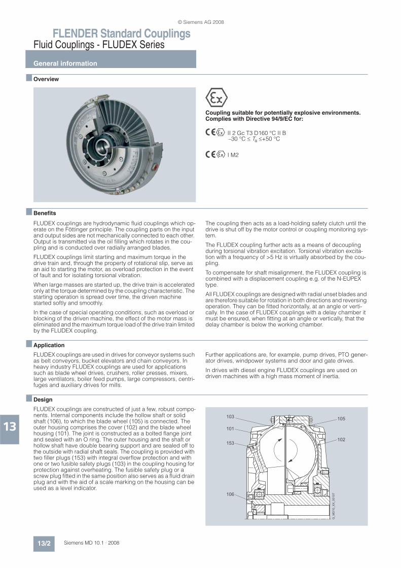
nDesign
FLUDEX couplings are constructed of just a few, robust compo-nents. Internal components include the hollow shaft or solid shaft (106), to which the blade wheel (105) is connected. The outer housing comprises the cover (102) and the blade wheel housing (101). The joint is constructed as a bolted flange joint and sealed with an O ring. The outer housing and the shaft or hollow shaft have double bearing support and are sealed off to the outside with radial shaft seals. The coupling is provided with two filler plugs (153) with integral overflow protection and with one or two fusible safety plugs (103) in the coupling housing for protection against overheating. The fusible safety plug or a screw plug fitted in the same position also serves as a fluid drain plug and with the aid of a scale marking on the housing can be used as a level indicator.
G_M
D10
_X
X_00107
103 105
102
101
153
106
© Siemens AG 2008

FLENDER Standard CouplingsFluid Couplings - FLUDEX Series
General information
13/3Siemens MD 10.1 · 2008
13
Materials
Blade wheel and housing
Cast aluminum AlSi10Mg
Shaft and hollow shaft
Steel with a yield point higher than 400 N/mm2
Static seals and radial shaft seals
Perbunan NBR or Viton FPM
Add-on parts
Grey cast iron EN-GJL-250, spheroidal graphite cast iron EN-GJS-400 or steel with a yield point higher than 400 N/mm2
Fusible safety plugs
If a FLUDEX coupling is operated with an impermissibly high slip for a prolonged period, the oil filling and the coupling housing will overheat. Fusible safety plugs which release the oil filling into the environment upon reaching a preset temperature are there-fore fitted in each coupling housing. These protect the coupling from irreparable damage through overheating or overpressure and disconnect the drive motor from the driven machine.
Thermal equipment
1) not available for size 222
Suitability:1 = suitable for continuous coupling operation temperatures
up to 85 °C2 = suitable for continuous coupling operation temperatures
up to 110 °C
The switchgear or sensor and evaluation instrument for the EOC system must be ordered separately, using the product code.
Thermal switching equipment
By adding thermal switching equipment leakage and loss of the hydraulic fluid as well as a risk to and contamination of the envi-ronment in the event that the coupling overheats can be avoided.
The thermal switching equipment does not work if a machine side is blocked and the coupling housing is connected to this side. If the coupling is stationary, the switching pin cannot actu-ate the switching equipment.
The thermal switching equipment comprises the thermal switch and the switchgear.
The switchgear comprises a limit switch with a make-and-break contact and a swiveling cam. Limit switch and cam are mounted on a common base plate. The thermal switch is screwed into the housing in place of a screw plug. The fusible safety plug (with a higher response temperature) remains in the coupling for addi-tional safety.
If the set temperature is exceeded, the switching pin is released from the fusible element, emerges 10 mm from the housing and actuates the switchgear while the coupling is rotating. The switchgear can cut out the drive motor and/or trigger an optical or acoustic alarm signal.
The housing of the coupling remains closed and no operating fluid will escape.
Assignment
From coupling size 297, the thermal switching equipment can be used up to a peripheral speed of 50 m/s. At higher speeds, an EOC system should be provided.
Equipment Suit-ability
Fusible safety plug Sealing material
Additional order info -Z with order code
1 110 °C NBR F01
FPM F05
Standard 1 140 °C NBR –
1 140 °C FPM F07
2 160 °C FPM F08
ATEX 1 110 °C ex NBR F02
FPM F06
With ther-mal switch1)
1 140 °C + thermal switch 110 °C
NBR F03
FPM F10
2 160 °C + thermal switch 140 °C
FPM F11
With EOC system1) transmitter
2 160 °C + EOC trans-mitter (125 °C)
NBR F04
FPM F12
Continuous operat-ing temperature
Thermal switch Fusible safety plug
%85 °C 110 °C 140 °C
>85 ° ... 110 °C 140 °C 160 °C
5
R
G_MD10_EN_00108
Striking area
Switchgear
Thermal switch
Size
297 342 370 395 425 450 490 516 565 590 655 755 887
Perm. speed in rpm 2500 2240 2100 2000 1900 1800 1650 1600 1500 1450 1250 1100 1000
Radius of travel R in mm 188 215 226 239 251 271 292 307 330 346 383 435 507
© Siemens AG 2008

FLENDER Standard CouplingsFluid Couplings - FLUDEX Series
General information
13/4 Siemens MD 10.1 · 2008
13
Switchgear: FFA 000000652020
EOC system
On the EOC system the temperature-dependent magnitude of the magnetic field of the EOC transmitter is measured and used for a switching pulse. The transmitter signal is transmitted via the fixed sensor to the evaluation instrument and there compared with the set value. If the signal does not exceed the minimum value or no signal is received, the relay of the evaluation instru-ment switches over. This can cause a malfunction message to be sent and the motor cut out. The coupling housing remains closed. The fusible safety plug with a higher response tempera-ture remains in the coupling for additional safety.
Components of the EOC system
Radius of travel R to the transmitter
L1
S1
S2
13
14
21
22
K1
K1
H1
F G_MD10_EN_00110
6 mm stroke
Limit switches
Wiring proposal
Motor
contactor
Snap-action contact
Code number 11
DIN EN 50013
ON
OFF
8
Ø9
48
18
20
52
22
44
12
4
70PG 13.5
G_M
D10
_E
N_00109a
Component Product code Note
EOC transmitter FFA 000000652781 Supplied with coupling
Seal FFA 000000306525
Sensor EOC FFA 000000361460 To be ordered separately
Evaluation instru-ment EWD
FFA 000001205294
Size
297 342 370 395 425 450 490 516 565 590 655 755 887
R in mm 188 215 226 239 251 271 292 346 330 346 383 435 507
1.
FLUDEX
70
2
M18 x 1
SW 24
R
G_M
D1
0_E
N_0
01
11
a
Evaluation instrument
Transmitter
Sensor
Bracket
(not part of
scope
of supply)
-K2
-U1
-B1
-K3
-H1-K3
43
13
14
2
1 13
11
31
32
12 9-
-BU
NAMUR
+BN
10+
14 15 16
5
5
6
7
8
8
3
4
2
33
-K2
-U1
33
342
-K3 21
223
-S3 21
222
-U1 5
34
-S1 11
12
-F1
L1
1
2
-K2 13
142
-F2 1.21
1.22
-K2 A1
A2
A1
A2
-K1
N
A1
A2
13
23
33
43
2
3
3
5
14
24
34
44
-K2 23
24
21
3
22
13
14 2
2
44
-S2
-S2
511
412 4
13
21
31
43
4
2
14
22
32
44
1
3
5
2
4
6
G_MD10_EN_00112
B1
F1
F2
H1
K1
K2
K3
S1
S2
S3
U1
Wiring proposal
Sensor
Fuse
Motor protection switch
Fault
Motor contactor
Contactor relay
Contactor relay
Emergency OFF
Motor OFF
Motor ON
Evaluation instrument
© Siemens AG 2008

FLENDER Standard CouplingsFluid Couplings - FLUDEX Series
General information
13/5Siemens MD 10.1 · 2008
13
n Function
Föttinger principle
Two opposing, radially bladed impellers are housed in a leak-proof housing. The impellers are not mechanically connected to each other. Because of the axially parallel arranged blades, the torque is transmitted independently of the direction of rotation and solely by the oil filling.
Hydrodynamic couplings have the characteristic properties of fluid flow engines. The transmissible torque depends on the density and quantity of the operating fluid and increases as the square of the drive speed and the fifth power of the profile diam-eter denoting the coupling size. In the driven pump impeller, me-chanical energy is converted into kinetic flow energy of the op-erating fluid. In the turbine impeller, which is connected to the output side, flow energy is converted back to mechanical en-ergy.
To generate the operating fluid circulation necessary for torque transmission, a difference in speed is necessary between the pump and turbine impellers. A centrifugal force pressure field is set up that is greater in the faster rotating pump impeller than in the turbine impeller. The difference in speed, usually termed “slip”, at the continuous operating point of the coupling is be-tween 2 % and 6 %, depending on application and coupling size. Immediately after drive motor start-up slip is 100 %, i.e. the pump impeller is driven at the speed of the motor, but the turbine impeller remains stationary.
Slip multiplied by the transmitted power represents the power loss of the coupling, which is converted into heat inside the oil filling. The amount of heat generated must be released into the environment via the coupling housing to prevent an impermissi-ble temperature rise. The rated coupling output is mainly deter-mined by the power loss which can be dissipated at a still ac-ceptable operating temperature or a reasonable set slip limit. This distinguishes the FLUDEX coupling from all positively act-ing coupling assembly options for which the rated coupling torque is the defining characteristic.
Depending on the FLUDEX coupling series, drive is via the inner rotor (shaft/hollow shaft with rigidly connected blade wheel) or via the bladed housing impeller (blade wheel housing). The driv-ing impeller is the pump impeller, and the driven impeller is the turbine impeller.
A low-viscosity mineral oil VG 22/VG 32, which also serves to lu-bricate the bearings, is used as fluid. In special types water, a water emulsion or low-flammability fluid may be used as a non-combustible fluid.
Slip-torque characteristics for different filling levels FG
The torque characteristic depends on the oil filling quantity FG in the coupling. This enables the transmissible torque on starting up to be set via the filling level. With a higher filling level the start-ing torque increases, while the operating slip and thus the cou-pling temperature rise decreases.
Conversely, with a lower filling level the starting torque de-creases, the coupling becomes softer, while slip and coupling temperature rise.
R1
R2
Cu1
Cu2
Motor
Pump
Fluid coupling
G_MD10_EN_00113
Turbine
Driven
machine
Pump impeller Turbine impeller
FG = 80%
FG = 75%
FG = 70%
FG = 65%
FG = 60%
FG = 55%
100%
0
0
50% 10% 0%
2
n
S
2
N SNSN
TN
= n1Slip
G_MD10_EN_00114
Torq
ue
Speed n
© Siemens AG 2008

FLENDER Standard CouplingsFluid Couplings - FLUDEX Series
General information
13/6 Siemens MD 10.1 · 2008
13
Operation of the delay chamber
Starting torque can be reduced without increasing continuous operating slip by using a type of coupling with a delay chamber. On these couplings part of the oil filling is initially stored inac-tively in the delay chamber. The starting torque is considerably reduced because of the thus reduced starting filling in the work-
ing chamber of the coupling. The filling in the delay chamber runs very slowly, mostly only at the finish of the starting opera-tion, from the delay chamber into the working chamber, causing the active filling in it to rise gradually and the continuous operat-ing slip to reach a value corresponding to the whole filling.
n Technical data
Balancing FLUDEX couplings
In deviation from the balancing specifications in catalog section 2, all FLUDEX couplings complying with DIN ISO 1940 are bal-anced to balancing quality G6.3 for 1800 rpm. For operating speeds higher than 1800 rpm micro-balancing, based on oper-ating speed, can be requested (order code +W03 required).
Balancing is a two-level balancing with the specified oil quantity or a 75 % filling.
FLUDEX couplings are balanced in accordance with the half parallel key standard. Other balancing standards must be spec-ified in the order, using the product code key (see catalog sec-tion 2).
Add-on couplings are subject to the standards as set out in cat-alog section 2.
Oil filling
FLUDEX couplings can be delivered with or without oil filling.• Delivery without oil filling:without order code
• Delivery with oil filling:product code with -Z and order code F16 and Y90 with plain text specification of the oil filling quantity in liters.
• Delivery without oil filling but with oil filling quantity specifica-tion: Product code with -Z and order code Y90 with plain text specification of the oil filling quantity in liters.
Hollow shafts of the FA, FG and FV series
Variant of FLUDEX hollow shafts only with finished bore: Order code for bore diameter is required.
Operating conditions for FLUDEX couplings in potentially explosive environments
The coupling with fusible safety plugs with identity marking T3 is suitable for the operating conditions set out in Directive
94/9/EC:
• Equipment group II (above-ground applications) temperature class T3 of categories 2 and 3 for environments where there are potentially explosive gas, vapors, mist and air mixtures and for environments where dust can form potentially explo-sive atmospheres.
• Equipment group I (below-ground applications) of category M2
If used in potentially explosive environments under ground, aluminum couplings must be provided with a robust enclo-sure to preclude the risk of ignition caused by e.g. friction, impact or friction sparks. The deposit of heavy-metal ox-ides (rust) on the coupling housing must be prevented by the enclosure or other suitable means.
FLUDEX couplings can be delivered with fitted brake disk or V-belt pulley.Designing the belt drive or the brake disk to conform with the guidelines is the responsibility of the subassembly sup-plier. It should be noted that there is a risk from, amongst other things, electrostatic charges and hot surfaces. Under BGR 132 (regulations of German Institute for Occu-pational Safety) the use of V-belts in conjunction with IIC gases is not permitted.
Axial retention
Axial retention is provided by a set screw or end washer with a retaining screw for shaft ends to DIN 748/1 with a centering thread to DIN 332/2. Other methods must be specified in the order, using the product code with -Z and order code Y99 with plain text specification.
Bore and keyway width tolerances are specified in catalog sec-tion 15.
Weights specified in the dimension order tables apply to maxi-mum bore diameters without oil filling.
Off Starting Continuous operation
G_M
D10
_E
N_00115
© Siemens AG 2008
FLENDER Standard CouplingsFluid Couplings - FLUDEX Series
General information
13/7Siemens MD 10.1 · 2008
13
nConfiguration
Selection of FLUDEX coupling
In accordance with the requirements catalog various series, sizes and types of FLUDEX coupling are available. The FLUDEX coupling series is characterized by various flow chamber config-urations, fitted delay chambers or fittings in the flow chamber. The types are determined by the design of the add-on coupling. This results in different starting factors and characteristics which
can be used for the most varied applications. The size is speci-fied by stating the flow outside diameter.
When selecting, the series required for the application, taking into account the starting factor and the characteristic, must be selected.
Selection of FLUDEX series
FLUDEX couplings which are to be used without special condi-tions solely as an aid to starting the motor can be selected using the assignment tables on page 13/12 (for n = 1500 rpm) or page13/14 (for n = 3000 rpm).
If special requirements, based on the operating method of the prime mover or driven machine, are made of the coupling or the coupling is to be used in extreme environmental conditions, please give specific details in the enquiry or order. The form “Technical specifications for the selection of type and size” can be used for this purpose.
Description of the FLUDEX series
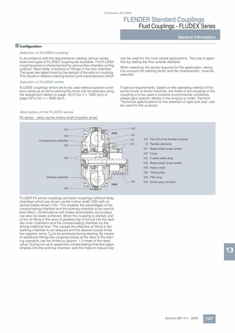
FA series – drive via the hollow shaft (impeller drive)
FLUDEX FA series couplings are basic couplings (without delay chamber) which are driven via the hollow shaft (106) with at-tached blade wheel (105). This enables the advantages of the compensating chamber and the working chamber to be used to best effect. Combinations with brake drums/disks and pulleys can also be easily achieved. When the coupling is started, part of the oil filling in the area of greatest slip is forced into the radi-ally inner chambers and the compensating chamber by the strong rotational flow. This causes the effective oil filling in the working chamber to be reduced and the desired torque limita-tion (approx. twice TN) to be achieved during starting. By means of additional fittings the coupling torque at the start of the start-ing operation can be limited to approx. 1.5 times of the rated value. During run-up to speed the compensating chamber again empties into the working chamber, and this helps to reduce slip.
153
2/3
12
101
102
103
105
106
120
153
163
101
12
2/3
103
102
105
106
163
120
FAD
FAR
Compensating chamber
Working chamber
Part 2/3 of the flexible coupling
Flexible elements
Blade wheel (outer wheel)
Cover
Fusible safety plug
Blade wheel (inner wheel)
Hollow shaft
V-belt pulley
Filler plug
Screw plug (oil drain)
G_M
D1
0_E
N_0
011
6
© Siemens AG 2008

FLENDER Standard CouplingsFluid Couplings - FLUDEX Series
General information
13/8 Siemens MD 10.1 · 2008
13
FG and FV series – drive via the housing
FLUDEX FG and FV series couplings are designed for drive via the coupling housing. In the FV series (coupling with delay chamber), the motor drives the coupling housing, comprising a blade wheel (101) and a cover (102), via the flexible N-EUPEX coupling (part 2/3) and the delay chamber (115). The rotational flow of the coupling filling drives the blade wheel (105) and the hollow shaft (106) on the output side, which is mounted on the gear unit or driven machine shaft. In the FG series (basic cou-pling), there is no delay chamber, and the flexible coupling is directly flange-mounted on the blade wheel.
When the coupling is started up, part of the oil filling is forced into the damming chamber. This enables the desired torque lim-itation (approx. twice TN) to be achieved during starting. In the FV series the delay chamber also receives part of the oil filling in accordance with the fluid level when the coupling is stationary. During starting the effective oil filling in the working chamber is
reduced by the amount of fluid in the delay chamber, thus con-siderably reducing the starting torque (approx. 1.5 times TN). From the delay chamber located on the drive side, the oil is fed back time-dependently to the working chamber via small holes and the coupling torque is raised, even if the output is blocked.
This replenishing function enables a drive to be soft-started with a very low starting torque and with an almost load-free motor. At the same time, however, increased load torques can be over-come by the torque increase in the coupling.
The property of the coupling with delay chamber can be used advantageously, for example, to soft-start empty, partly loaded and fully loaded conveyor belts.
FG series couplings are used for normal starting torque limita-tion, as a starting clutch for isolating vibration and for overload limitation in the event of drive blockage.
2/3
2/3
12
103
102
105
101
153
12
163
106
115
173
2/3
12
101
102
103
105
106
115
153
163
173
Damming
chamber
FGD
FVD
Working
chamber
Part 2/3 of the flexible coupling
Flexible elements
Blade wheel (outer wheel)
Cover
Fusible safety plug
Blade wheel (inner wheel)
Hollow shaft
Delay chamber
Filler plug
Screw plug (oil drain)
Oil drain plug - delay chamber
G_M
D10
_E
N_00117
© Siemens AG 2008
FLENDER Standard CouplingsFluid Couplings - FLUDEX Series
General information
13/9Siemens MD 10.1 · 2008
13
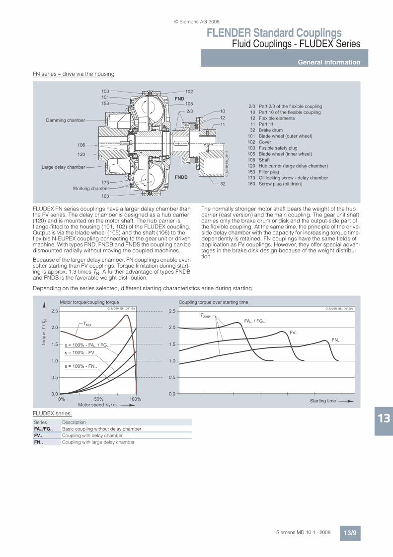
FN series – drive via the housing
FLUDEX FN series couplings have a larger delay chamber than the FV series. The delay chamber is designed as a hub carrier (120) and is mounted on the motor shaft. The hub carrier is flange-fitted to the housing (101, 102) of the FLUDEX coupling. Output is via the blade wheel (105) and the shaft (106) to the flexible N-EUPEX coupling connecting to the gear unit or driven machine. With types FND, FNDB and FNDS the coupling can be dismounted radially without moving the coupled machines.
Because of the larger delay chamber, FN couplings enable even softer starting than FV couplings. Torque limitation during start-ing is approx. 1.3 times TN. A further advantage of types FNDB and FNDS is the favorable weight distribution.
The normally stronger motor shaft bears the weight of the hub carrier (cast version) and the main coupling. The gear unit shaft carries only the brake drum or disk and the output-side part of the flexible coupling. At the same time, the principle of the drive-side delay chamber with the capacity for increasing torque time-dependently is retained. FN couplings have the same fields of application as FV couplings. However, they offer special advan-tages in the brake disk design because of the weight distribu-tion.
Depending on the series selected, different starting characteristics arise during starting.
FLUDEX series:
2/3
10
12
11
32
101
102
103
105
106
120
153
173
163
103
101
153
173
102
105
2/3 10
12
11
32
163
106
120
G_M
D10
_E
N_00118
FND
FNDB
Part 2/3 of the flexible coupling
Part 10 of the flexible coupling
Flexible elements
Part 11
Brake drum
Blade wheel (outer wheel)
Cover
Fusible safety plug
Blade wheel (inner wheel)
Shaft
Hub carrier (large delay chamber)
Filler plug
Oil locking screw - delay chamber
Screw plug (oil drain)Working chamber
Damming chamber
Large delay chamber
FA.. / FG..
FV..
FN..
Starting time
Coupling torque over starting time
G_MD10_EN_00120a2.5
2.0
1.5
1.0
0.5
0.0
couplT
T
s = 100% - FA.. / FG..
s = 100% - FV.
s = 100% - FN..
/N
Mot
100%50%0%
TT
/1n 0n
Torq
ue
Motor speed
Motor torque/coupling torque
G_MD10_EN_00119a2.5
2.0
1.5
1.0
0.5
0.0
Series Description
FA../FG.. Basic coupling without delay chamber
FV.. Coupling with delay chamber
FN.. Coupling with large delay chamber
© Siemens AG 2008
FLENDER Standard CouplingsFluid Couplings - FLUDEX Series
General information
13/10 Siemens MD 10.1 · 2008
13
Selection of FLUDEX type
Listed in the catalog are FLUDEX couplings with pulley, brake drum, brake disk and flexible N-EUPEX coupling. Further types, e.g. in combination with a torsionally rigid steel
membrane coupling of the ARPEX series or a highly flexible cou-pling of the ELPEX or ELPEX-S series, are available.
The maximum shaft displacements permissible for an N-EUPEX add-on coupling are shown in catalog section 7. For greater shaft displacements FLUDEX couplings can be combined with cardan shafts or other displacement couplings.
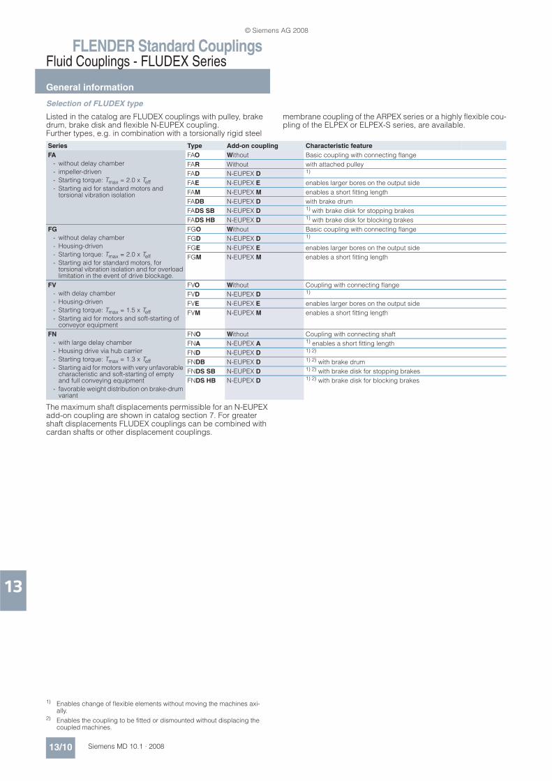
Series Type Add-on coupling Characteristic feature
FA
- without delay chamber
- impeller-driven
- Starting torque: Tmax = 2.0 x Teff- Starting aid for standard motors and torsional vibration isolation
FAO Without Basic coupling with connecting flange
FAR Without with attached pulley
FAD N-EUPEX D 1)
FAE N-EUPEX E enables larger bores on the output side
FAM N-EUPEX M enables a short fitting length
FADB N-EUPEX D with brake drum
FADS SB N-EUPEX D 1) with brake disk for stopping brakes
FADS HB N-EUPEX D 1) with brake disk for blocking brakes
FG
- without delay chamber
- Housing-driven
- Starting torque: Tmax = 2.0 x Teff- Starting aid for standard motors, for torsional vibration isolation and for overload limitation in the event of drive blockage.
FGO Without Basic coupling with connecting flange
FGD N-EUPEX D 1)
FGE N-EUPEX E enables larger bores on the output side
FGM N-EUPEX M enables a short fitting length
FV
- with delay chamber
- Housing-driven
- Starting torque: Tmax = 1.5 x Teff- Starting aid for motors and soft-starting of conveyor equipment
FVO Without Coupling with connecting flange
FVD N-EUPEX D 1)
FVE N-EUPEX E enables larger bores on the output side
FVM N-EUPEX M enables a short fitting length
FN
- with large delay chamber
- Housing drive via hub carrier
- Starting torque: Tmax = 1.3 x Teff- Starting aid for motors with very unfavorable characteristic and soft-starting of empty and full conveying equipment
- favorable weight distribution on brake-drum variant
FNO Without Coupling with connecting shaft
FNA N-EUPEX A 1) enables a short fitting length
FND N-EUPEX D 1) 2)
FNDB N-EUPEX D 1) 2) with brake drum
FNDS SB N-EUPEX D 1) 2) with brake disk for stopping brakes
FNDS HB N-EUPEX D 1) 2) with brake disk for blocking brakes
1) Enables change of flexible elements without moving the machines axi-ally.
2) Enables the coupling to be fitted or dismounted without displacing the coupled machines.
© Siemens AG 2008
FLENDER Standard CouplingsFluid Couplings - FLUDEX Series
General information
13/11Siemens MD 10.1 · 2008
13
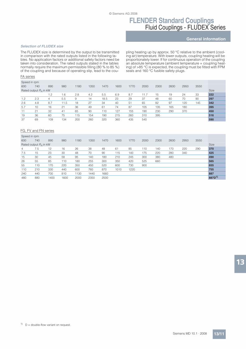
Selection of FLUDEX size
The FLUDEX size is determined by the output to be transmitted in comparison with the rated outputs listed in the following ta-bles. No application factors or additional safety factors need be taken into consideration. The rated outputs stated in the tables normally require the maximum permissible filling (80 % to 85 %) of the coupling and because of operating slip, lead to the cou-
pling heating up by approx. 50 °C relative to the ambient (cool-ing air) temperature. With lower outputs, coupling heating will be proportionately lower. If for continuous operation of the coupling an absolute temperature (ambient temperature + coupling heat-ing) of >85 °C is expected, the coupling must be fitted with FPM seals and 160 °C fusible safety plugs.
FA series
FG, FV and FN series
Speed in rpm
600 740 890 980 1180 1350 1470 1600 1770 2000 2300 2600 2950 3550
Rated output PN in kW Size
1.2 1.6 2.8 4.2 5.5 6.9 8.7 11.7 15 19 24 33 222
1.2 2.3 4 5.5 9 14 18.5 23 29 37 48 60 70 90 297
2.6 4.8 8.7 11.5 18 27 34 40 51 65 82 97 120 145 342
5.7 10 16 21 36 49 61 74 87 105 135 165 180 395
11 21 32 41 65 90 110 127 155 190 230 290 370 450
19 36 60 75 115 154 190 215 260 310 395 516
37 69 109 134 200 260 320 360 435 540 590
Speed in rpm
600 740 890 980 1180 1350 1470 1600 1770 2000 2300 2600 2950 3550
Rated output PN in kW Size
4 7.5 12 16 26 38 48 61 85 110 140 170 220 290 370
7.5 15 23 30 48 70 90 115 140 175 220 280 340 425
15 30 45 58 95 140 180 210 245 300 380 480 490
28 55 85 110 180 255 300 350 420 525 660 565
55 110 170 220 350 450 520 600 730 900 655
110 210 330 440 600 760 870 1010 1220 755
240 440 700 810 1130 1440 1660 887
480 880 1400 1600 2000 2350 2500 887D1)
1) D = double-flow variant on request.
© Siemens AG 2008

FLENDER Standard CouplingsFluid Couplings - FLUDEX Series
FLUDEX coupling as aid to starting IEC motors
13/12 Siemens MD 10.1 · 2008
13
n Selection and ordering data
Speed n = 1500 rpm
This assignment offers safety in normal load cases and includes standard types with 140 °C fusible safety plugs, for horizontal fitting and an ambient air temperature from –40 °C to +40 °C.
1) If the recommended number of belts is ..X, raw-edged belts are required.
2) Larger bores on the output side are possible with type FAE.
L1
LG L1 S NL2
LG
ØD
1
ØD
1
ØD
A
ØD
2
ØD
A
G_M
D10
_E
N_00121a
V-belt pulleyOutput
Type FAR Type FAD
Part 3
Part 2Output
ØD
3 =
N-E
UP
EX
siz
e
Three-phase motor FLUDEX Type FAR (with V-belt pulley) Type FAD (with N-EUPEX D add-on coupling)
Size PM Size Oil filling
DA Pro-file, pitch Ø
No. of grooves
Recom-mended no. of belts 1)
LG Product code Weight LG NL2 D3 D22) Product code Weight
1500 rpm
D1x L1
with order codes for bore diameters and tolerances (product code without -Z)– selection in catalog part 3
with order codes for bore diameters and tolerances (product code without -Z)– selection in catalog part 3
Available ex stock
Available at short term m max. Available at short term m
kW mm l mm mm mm kg mm mm mm mm kg
80 M 0.55 19 x 40
222 0.9 263 SPZ 100
2 1 153 2LC0900-0AF90-0AA0L0L
12 180 40 110 38 2LC0900-0AA9L0L+M..
n -0AA0 12
80 M 0.75 19 x 40
1.0 SPZ 100
2 1 2LC0900-0AF90-0AA0L0L
2LC0900-0AA9L0L+M..
n -0AA0
90 S 1.1 24 x 50
1.1 SPZ 100
2 1 2LC0900-0AF90-0AA0L0P
2LC0900-0AA9L0P+M..
n -0AA0
90 L 1.5 24 x 50
1.2 SPZ 100
2 1 2LC0900-0AF90-0AA0L0P
2LC0900-0AA9L0P+M..
n -0AA0
100 L 2.2 28 x 60
1.4 SPZ 100
2 2 2LC0900-0AF90-0AA0L0R
2LC0900-0AA9L0R+M..
n -0AA0
100 L 3 28 x 60
1.5 SPZ 100
2 2 2LC0900-0AF90-0AA0L0R
2LC0900-0AA9L0R+M..
n -0AA0
112 M 4 28 x 60
1.6 SPZ 160
3 2 2LC0900-0AF91-0AA0L0R
14 2LC0900-0AA9L0R+M..
n -0AA0
132 S 5.5 38 x 80
1.65 SPZ 160
3 2 2LC0900-0AF91-0AA0L0V
2LC0900-0AA9L0V+M..
n -0AA0
'D2: • Without finished bore 1
• With finished bore – With order codes for diameter and tolerance (product code without -Z) 9
© Siemens AG 2008

FLENDER Standard CouplingsFluid Couplings - FLUDEX Series
FLUDEX coupling as aid to starting IEC motors
13/13Siemens MD 10.1 · 2008
13
Delivery without oil filling: Without order code.
Delivery with oil filling (only above –20 °C): Product code with “-Z” and order codes “F16” and “Y90” with plain text specifica-tion of the oil filling quantity in liters.
Delivery with specification of oil filling quantity: Product code with “-Z” and order code “Y90” with plain text specification of the oil filling quantity in liters.
Axial retention is provided by a set screw and/or end washer with a retaining screw for shaft ends to DIN 748/1 with a centering thread to DIN 332/2. Other methods must be specified in the order using the product code with “-Z” and order code “Y99” with plain text specifica-tion.
Ordering example:Drive with motor 200 L, 30 kW at 1470 rpm with starting clutch and pulley
Selection: FLUDEX FAR 342 coupling, standard type, Hollow shaft: Bore ØD1 = 55H7 with keyway to DIN 6885/1 and retaining screw, with pulley 5xSPA Ø180.
Product code:
• Delivery without oil filling: 2LC0900-2AF90-0AA0L1D
• Delivery with oil filling: 2LC0900-1AF90-0AA0-ZL1D+F16+Y90plain text to Y90: 6.0 l
• Delivery with specification of oil filling quantity: 2LC0900-1AF90-0AA0-ZL1D+Y90plain text to Y90: 6.0 l
Three-phase motor FLUDEX Type FAR (with V-belt pulley) Type FAD (with N-EUPEX D add-on coupling)
Size PM Size Oil filling
DA Pro-file, pitch Ø
No. of grooves
Recom-mended no. of belts 1)
LG Product code Weight LG NL2 D3 D22) Product code Weight
1500 rpm
D1x L1
with order codes for bore diameters and tolerances (product code without -Z)– selection in catalog part 3
with order codes for bore diameters and tolerances (product code without -Z)– selection in catalog part 3
Available ex stock
Available at short term m max. Available at short term m
kW mm l mm mm mm kg mm mm mm mm kg
132 M 7.5 38 x 80
297 3.2 340 SPZ 150
5 3 226 2LC0900-1AF90-0AA0L0V
27 233 50 125 45 2LC0900-1AA9L0V+M..
n -0AA0 24
160 M 11 42 x 110
3.5 SPZ 150
5 4 2LC0900-1AF90-0AA0L0X
2LC0900-1AA9L0X+M..
n -0AA0
160 L 15 42 x 110
3.8 SPZ 150
5 5 2LC0900-1AF90-0AA0L0X
2LC0900-1AA9L0X+M..
n -0AA0
180 M 18.5 48 x 110
4.0 SPA 190
4 4 2LC0900-1AF91-0AA0L1B
32 2LC0900-1AA9L1B+M..
n -0AA0
180 L 22 48 x 110
342 5.5 400 SPA 180
5 5 278 2LC0900-2AF90-0AA0L1B
40 271 55 140 50 2LC0900-2AA9L1B+M..
n -0AA0 34
200 L 30 55 x 110
6.0 SPA 180
5 5X 2LC0900-2AF90-0AA0L1D
2LC0900-2AA9L1D+M..
n -0AA0
225 S 37 60 x 140
395 7.6 448 SPB 224
5 5 325 2LC0900-3AF90-0AA0L1E
63 299 90 225 85 2LC0900-3AA9L1E+M..
n -0AA0 53
225 M 45 60 x 140
7.9 SPB 224
5 5 2LC0900-3AF90-0AA0L1E
2LC0900-3AA9L1E+M..
n -0AA0
250 M 55 65 x 140
8.4 SPB 224
5 5X 2LC0900-3AF90-0AA0L1F
2LC0900-3AA9L1F+M..
n -0AA0
280 S 75 75 x 140
450 10.8 512 SPB 250
8 7 410 2LC0900-4AF90-0AA0L1H
94 338 100 250 95 2LC0900-4AA9L1H+M..
n -0AA0 70
280 M 90 75 x 140
11.3 SPB 250
8 8 2LC0900-4AF90-0AA0L1H
2LC0900-4AA9L1H+M..
n -0AA0
315 S 110 80 x 170
12.0 SPB 250
8 8X 2LC0900-4AF90-0AA0L1J
2LC0900-4AA9L1J+M..
n -0AA0
315 M 132 80 x 170
516 17.7 584 SPB 315
10 10 491 2LC0900-5AF90-0AA0L1J
152 398 125 315 120 2LC0900-5AA9L1J+M..
n -0AA0 113
315 M 160 80 x 170
18.6 SPB 315
10 10X 2LC0900-5AF90-0AA0L1J
2LC0900-5AA9L1J+M..
n -0AA0
'D2: • Without finished bore for sizes 222 to 450 and 516 with small hub ('D2 max. 100 mm) – Without order code M.. 1
• Without finished bore only for size 516 with large hub ('D2 max. 88 … 120 mm) – Without order code M.. 2
• With finished bore – With order codes for diameter and tolerance (product code without -Z) 9
1) If the recommended number of belts is ..X, raw-edged belts are required.
2) Larger bores on the output side are possible with type FAE.
© Siemens AG 2008
FLENDER Standard CouplingsFluid Couplings - FLUDEX Series
FLUDEX coupling as aid to starting IEC motors
13/14 Siemens MD 10.1 · 2008
13
n Selection and ordering data
Speed n = 3000 rpmThis assignment offers safety in normal load cases and includes standard types with 140 °C fusible safety plugs, for horizontal fitting and an ambient air temperature from –40 °C to +40 °C.
1) If the recommended number of belts is ..X, raw-edged belts are required.
2) Larger bores on the output side are possible with type FAE.
3) Variant with shallow keyway to DIN 6885/3.
L1
LG L1 S NL2
LG
ØD
1
ØD
1
ØD
A
ØD
2
ØD
A
G_M
D10
_E
N_00121a
V-belt pulleyOutput
Type FAR Type FAD
Part 3
Part 2Output
ØD
3 =
N-E
UP
EX
siz
e
Three-phase motor
FLUDEX Type FAR (with V-belt pulley) Type FAD (with N-EUPEX D add-on coupling)
Size PM Size Oil fill-ing
DA Pro-file, pitch Ø
No. of grooves
Recom-mended no. of belts 1)
LG Product code Weight LG NL2 D3 D22) Product code Weight
3000 rpm
D1x L1
with order codes for bore diameters and tolerances (product code without -Z)– selection in catalog part 3
max. with order codes for bore diameters and tolerances (product code without -Z)– selection in catalog part 3
Available at short term m Available at short term m
kW mm l mm mm mm kg mm mm mm mm kg
90 S 1.5 24 x 50
222 0.7 263 SPZ 100
2 1 153 2LC0900-0AF90-0AA0-Z L0P+W03
12 180 40 110 38 2LC0900-0AA9 L0P+M..+W03
n -0AA0-Z 12
90 L 2.2 24 x 50
0.8 SPZ 100
2 1 2LC0900-0AF90-0AA0-Z L0P+W03
2LC0900-0AA9 L0P+M..+W03
n -0AA0-Z
100 L 3 28 x 60
0.9 SPZ 100
2 1 2LC0900-0AF90-0AA0-Z L0R+W03
2LC0900-0AA9 L0R+M..+W03
n -0AA0-Z
112 M 4 28 x 60
1.0 SPZ 100
2 2 2LC0900-0AF90-0AA0-Z L0R+W03
2LC0900-0AA9 L0R+M..+W03
n -0AA0-Z
132 S 5.5 38 x 80
1.0 SPZ 100
2 2 2LC0900-0AF90-0AA0-Z L0V+W03
2LC0900-0AA9 L0V+M..+W03
n -0AA0-Z
132 S 7.5 38 x 80
1.1 SPZ 160
3 2 2LC0900-0AF91-0AA0-Z L0V+W03
14 2LC0900-0AA9 L0V+M..+W03
n -0AA0-Z
160 M 11 423) x 110
1.2 SPZ 160
3 2 2LC0900-0AF91-0AA0-Z L0X+W03
2LC0900-0AA9 L0X+M..+W03
n -0AA0-Z
160 M 15 423) x 110
1.3 SPZ 160
3 3 2LC0900-0AF91-0AA0-Z L0X+W03
2LC0900-0AA9 L0X+M..+W03
n -0AA0-Z
160 L 18.5 423) x 110
1.4 SPZ 160
3 3 2LC0900-0AF91-0AA0-Z L0X+W03
2LC0900-0AA9 L0X+M..+W03
n -0AA0-Z
'D2: • Without finished bore – Without order code M.. 1
• With finished bore – With order codes for diameter and tolerance (product code without -Z) 9
© Siemens AG 2008

FLENDER Standard CouplingsFluid Couplings - FLUDEX Series
FLUDEX coupling as aid to starting IEC motors
13/15Siemens MD 10.1 · 2008
13
Delivery without oil filling: Without order code.
Delivery with oil filling (only above –20 °C): Product code with “-Z” and order codes “F16” and “Y90” with plain text specifica-tion of the oil filling quantity in liters.
Delivery with specification of oil filling quantity: Product code with “-Z” and order code “Y90” with plain text specification of the oil filling quantity in liters.
Axial retention is provided by a set screw and/or end washer with a retaining screw for shaft ends to DIN 748/1 with a centering thread to DIN 332/2. Other methods must be specified in the order using the product code with “-Z” and order code “Y99” with plain text specifica-tion.
Ordering example:Drive with motor 280 M, 90 kW at 2950 rpm with starting clutch for connecting two shafts.
Selection: FLUDEX FAD 395 coupling, standard type, Hollow shaft: Bore ØD1 = 65H7 with keyway to DIN 6885/1 and retaining screw, Part 2: Bore ØD2 = 60H7 with keyway to DIN 6885/1 and set screw.
Product code:
• Delivery without oil filling: 2LC0900-3AA99-0AA0-ZL1F+M1E+W03
• Delivery with oil filling: 2LC0900-3AA99-0AA0-ZL1F+M1E+W03+F16+Y90plain text to Y90: 5.6 l
• Delivery with specification of oil filling quantity: 2LC0900-3AA99-0AA0-ZL1F+M1E+W03+Y90plain text to Y90: 5.6 l
180 M 22 48 x 110
297 2.5 340 SPZ 150
5 4 226 2LC0900-1AF90-0AA0-Z L1B+W03
27 233 50 125 45 2LC0900-1AA9 L1B+M..+W03
n -0AA0-Z 24
200 L 30 55 x 110
2.7 SPZ 150
5 5 2LC0900-1AF90-0AA0-Z L1D+W03
2LC0900-1AA9 L1D+M..+W03
n -0AA0-Z
200 L 37 55 x 110
2.8 SPA 190
4 4 2LC0900-1AF91-0AA0-Z L1D+W03
32 2LC0900-1AA9 L1D+M..+W03
n -0AA0-Z
225 M 45 55 x 110
2.9 SPA 224
5 4 2LC0900-1AF92-0AA0-Z L1D+W03
35 2LC0900-1AA9 L1D+M..+W03
n -0AA0-Z
250 M 55 603) x 140
3.1 SPA 224
5 5 2LC0900-1AF92-0AA0-Z L1E+W03
2LC0900-1AA9 L1E+M..+W03
n -0AA0-Z
280 S 75 65 x 140
395 5.3 448 SPB 236
7 5 363.5 2LC0900-3AF91-0AA0-Z L1F+W03
70 299 90 225 85 2LC0900-3AA9 L1F+M..+W03
n -0AA0-Z 53
280 M 90 65 x 140
5.6 SPB 236
7 6 2LC0900-3AF91-0AA0-Z L1F+W03
2LC0900-3AA9 L1F+M..+W03
n -0AA0-Z
315 S 110 65 x 140
5.9 SPB 236
7 7 2LC0900-3AF91-0AA0-Z L1F+W03
2LC0900-3AA9 L1F+M..+W03
n -0AA0-Z
315 M 132 65 x 140
6.2 SPB 236
7 7X 2LC0900-3AF91-0AA0-Z L1F+W03
2LC0900-3AA9 L1F+M..+W03
n -0AA0-Z
315 L 160 65 x 140
6.8 SPB 280
7 7X 2LC0900-3AF92-0AA0-Z L1F+W03
83 2LC0900-3AA9 L1F+M..+W03
n -0AA0-Z
Three-phase motor
FLUDEX Type FAR (with V-belt pulley) Type FAD (with N-EUPEX D add-on coupling)
Size PM Size Oil fill-ing
DA Pro-file, pitch Ø
No. of grooves
Recom-mended no. of belts 1)
LG Product code Weight LG NL2 D3 D22) Product code Weight
3000 rpm
D1x L1
with order codes for bore diameters and tolerances (product code without -Z)– selection in catalog part 3
max. with order codes for bore diameters and tolerances (product code without -Z)– selection in catalog part 3
Available at short term m Available at short term m
kW mm l mm mm mm kg mm mm mm mm kg
'D2: • Without finished bore – Without order code M.. 1
• With finished bore – With order codes for diameter and tolerance (product code without -Z) 9
1) If the recommended number of belts is ..X, raw-edged belts are required.
2) Larger bores on the output side are possible with type FAE.
3) Variant with shallow keyway to DIN 6885/3.
© Siemens AG 2008

FLENDER Standard CouplingsFluid Couplings - FLUDEX Series
Type FAO
13/16 Siemens MD 10.1 · 2008
13
n Selection and ordering data
Basic coupling of the FA series with connecting flange.
Ordering example:Motor 37 kW, Peff = 30 kW, n1 = 1470 rpm, maximum output torque: Tmax = 2.0 x Teff.
Selection:FLUDEX FAO coupling size 342, Hollow shaft: Bore ØD1 = 60H7 mm with keyway to DIN 6885/3 and retaining screw, seal set Viton.Specification of oil filling quantity: 6.0 l (see under oil filling quan-tities for the FA series in this catalog section).
Product code:
• With 110°C fuse: 2LC0900-2AG90-0AA0-ZL1E+Y90+F05plain text to Y90: 6.0 l
• With 140°C fuse: 2LC0900-2AG90-0AA0-ZL1E+Y90+F07plain text to Y90: 6.0 l
ØD
FK
ØD
FA
J7
ØD
FN
ZF
xM
ØD
FK
ØD
FN
j7
ØD
FA
ZF
xM
ØD
A
ØD
1
L1
L6 T BF
L3
L6 T BF
L3
LGØ
DA
ØD
1
L1
LG
Sizes 297 ... 590
OutputDrive
Hollow shaft
OutputDrive
Hollow shaft
Size 222
G_M
D10
_E
N_00122a
Size Maxi-mum speed
Dimensions in mm Tightening torque
for screws in thread ZF x M
Product code Weight
Flange connection with order codes for bore diameters and tolerances (product code without -Z)– selection in catalog part 3
nKmax D1 L1 DA LG L3 L6 DFN DFA BF DFK ZF x M T m
Keyway to DIN 6885 TA
min. max. Pre-ferred bore
max. In standard type avail-able ex stock
Available at short term
rpm Nm kg
222 3600 38 28 80 263 112 110 58 90 144 2 128 6 x M8 12 18.7 2LC0900-0AG90-0AA0 L..
10
>381) 421)
297 3600 38 80 340 150 145 83 125 195 3 172 6 x M8 12 18.7 2LC0900-1AG90-0AA0 L..
18
>38 55 42 110
>551) 601) 110
342 3600 55 48 + 55 110 400 180 174 101 140 230 4 205 8 x M10 15 31 2LC0900-2AG90-0AA0 L..
26
>551) 601) 120
395 3000 65 60 + 65 140 448 205 200.5 110.5 225 290 4 265 8 x M12 18 54 2LC0900-3AG90-0AA0 L..
40
450 3000 75 65 + 75 140 512 233 228 126 250 310 4 285 8 x M12 18 54 2LC0900-4AG90-0AA0 L..
53
>75 80 170
516 2300 55 140 584 270 263 147 315 390 5 360 8 x M16 24 135 2LC0900-5AG90-0AA0 L..
84
>55 90 80 170
590 2000 75 140 662 305 298 166 315 390 5 360 8 x M16 24 135 2LC0900-6AG90-0AA0 L..
109
>75 95 170
>95 100 210
1) Variant with shallow keyway to DIN 6885/3.
© Siemens AG 2008

FLENDER Standard CouplingsFluid Couplings - FLUDEX Series
Type FAR with attached V-belt pulley
13/17Siemens MD 10.1 · 2008
13
n Selection and ordering data
General specifications and ordering instructions on page 13/10, 13/11. Ordering example on page 13/24.
ØD
A
ØD
1
ØD
1
A
F
A
F
L1
LG
L6
ØD
A
ØD
1
A
FA
F
L6
ØD
1
L1
LG
Variants A and G Variants N and H
V-belt pulleyOutput
V-belt pulleyOutput
G_MD10_EN_00123
Hollow shaft
Drive
Hollow shaft
Drive
Variant HVariant NVariant GVariant A
Size Maxi-mum speed
Dimensions in mm Product code Weight
V-belt pulley with order codes for bore diameters and tolerances (product code without -Z)– selection in catalog part 3
nKmax D1 L1 DA LG L6 Profile, pitch diameter
No. of grooves
A F Variant m
Keyway to DIN 6885
min. max. Pre-ferred bore
max. In standard type avail-able ex stock
Available at short term
rpm kg
222 3600 28 28 60 263 153 95 SPZ 100 2 1 9 A 2LC0900-0AF90-0AA0 L..
12
>28 38 105 SPZ 160 3 G 2LC0900-0AF91-0AA0 L..
14
>381) 421) 110
297 3600 38 80 340 226 143 SPZ 150 5 2 10 N 2LC0900-1AF90-0AA0 L..
27
>38 55 42 110 SPZ 150 5 2 N 2LC0900-1AF90-0AA0 L..
27
>551) 591) 110 SPA 190 4 0 H 2LC0900-1AF91-0AA0 L..
32
>591) 601) 140 SPA 224 5 0 G 2LC0900-1AF92-0AA0 L..
35
342 3600 55 55 110 400 278 177 SPA 180 5 4 14 N 2LC0900-2AF90-0AA0 L..
40
395 3000 55 110 448 325 214.5 SPB 224 5 4 16.5 N 2LC0900-3AF90-0AA0 L..
63
>55 65 60 + 65 140
3000 55 110 448 363.5 253 SPB 236 7 N 2LC0900-3AF91-0AA0 L..
70
>55 75 140
2700 SPB 280 7 H 2LC0900-3AF92-0AA0 L..
83
450 3000 55 110 512 410 284 SPB 250 8 4 16.5 N 2LC0900-4AF90-0AA0 L..
94
>55 75 65 + 75 140
>75 80 170
516 2300 55 110 584 491 344 SPB 315 10 4 16.5 N 2LC0900-5AF90-0AA0 L..
152
>55 75 140
>75 95 170
>95 100 210
590 2000 55 110 662 642 476 SPC 315 12 4 21 N 2LC0900-6AF90-0AA0 L..
208
>55 75 140
>75 95 170
>95 100 210
1) Variant with shallow keyway to DIN 6885/3.
© Siemens AG 2008
FLENDER Standard CouplingsFluid Couplings - FLUDEX Series
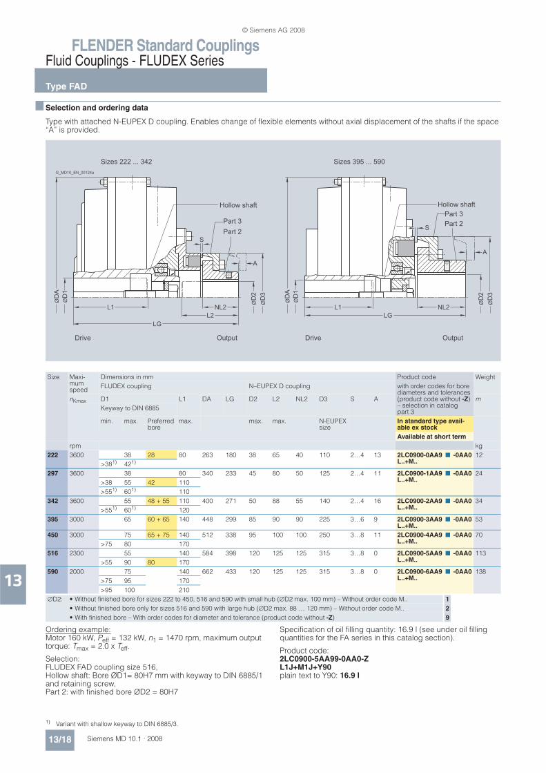
Type FAD
13/18 Siemens MD 10.1 · 2008
13
n Selection and ordering data
Type with attached N-EUPEX D coupling. Enables change of flexible elements without axial displacement of the shafts if the space “A” is provided.
Ordering example:Motor 160 kW, Peff = 132 kW, n1 = 1470 rpm, maximum output torque: Tmax = 2.0 x Teff.
Selection: FLUDEX FAD coupling size 516, Hollow shaft: Bore ØD1= 80H7 mm with keyway to DIN 6885/1 and retaining screw, Part 2: with finished bore ØD2 = 80H7
Specification of oil filling quantity: 16.9 l (see under oil filling quantities for the FA series in this catalog section).
Product code:2LC0900-5AA99-0AA0-ZL1J+M1J+Y90plain text to Y90: 16.9 l
ØD
A
ØD
1
L1 NL2
L2
L1 NL2
LG
LG
ØD
2
A
S
ØD
3
ØD
2
A
ØD
3
ØD
A
ØD
1
S
Hollow shaft
Sizes 222 ... 342
G_MD10_EN_00124a
Drive Output
Part 3
Part 2
Sizes 395 ... 590
Hollow shaft
Drive Output
Part 3
Part 2
Size Maxi-mum speed
Dimensions in mm Product code Weight
FLUDEX coupling N–EUPEX D coupling with order codes for bore diameters and tolerances (product code without -Z)– selection in catalog part 3
nKmax D1 L1 DA LG D2 L2 NL2 D3 S A m
Keyway to DIN 6885
min. max. Preferred bore
max. max. max. N-EUPEX size
In standard type avail-able ex stock
Available at short term
rpm kg
222 3600 38 28 80 263 180 38 65 40 110 2…4 13 2LC0900-0AA9L..+M..
n -0AA0 12
>381) 421)
297 3600 38 80 340 233 45 80 50 125 2…4 11 2LC0900-1AA9L..+M..
n -0AA0 24
>38 55 42 110
>551) 601) 110
342 3600 55 48 + 55 110 400 271 50 88 55 140 2…4 16 2LC0900-2AA9L..+M..
n -0AA0 34
>551) 601) 120
395 3000 65 60 + 65 140 448 299 85 90 90 225 3…6 9 2LC0900-3AA9L..+M..
n -0AA0 53
450 3000 75 65 + 75 140 512 338 95 100 100 250 3…8 11 2LC0900-4AA9L..+M..
n -0AA0 70
>75 80 170
516 2300 55 140 584 398 120 125 125 315 3…8 0 2LC0900-5AA9L..+M..
n -0AA0 113
>55 90 80 170
590 2000 75 140 662 433 120 125 125 315 3…8 0 2LC0900-6AA9L..+M..
n -0AA0 138
>75 95 170
>95 100 210
'D2: • Without finished bore for sizes 222 to 450, 516 and 590 with small hub ('D2 max. 100 mm) – Without order code M.. 1
• Without finished bore only for sizes 516 and 590 with large hub ('D2 max. 88 … 120 mm) – Without order code M.. 2
• With finished bore – With order codes for diameter and tolerance (product code without -Z) 9
1) Variant with shallow keyway to DIN 6885/3.
© Siemens AG 2008

FLENDER Standard CouplingsFluid Couplings - FLUDEX Series
Type FAE
13/19Siemens MD 10.1 · 2008
13
n Selection and ordering data
Type with attached N-EUPEX E coupling. Enables larger bores on the output side.
Weights specified in the table apply to maximum bore diameters without oil filling.
Ordering example:Motor 45 kW, Peff = 42 kW, n1 = 2950 rpm
Selection: FLUDEX FAE coupling size 342, Hollow shaft: Bore ØD1= 55H7 mm with keyway to DIN 6885/1 and retaining screw, Part 4: Bore ØD2 = 60H7 with keyway to DIN 6885/1 and set screw, with micro-balancing (high speed), with electronic or mechanical operation monitoring, seal set Perbunan. Delivery without oil filling, no oil filling quantity specification.
Product code:
• With 110 °C thermal switch: 2LC0900-2AB99-0AA0-ZL1D+M1E+W03+F03plain text to Y90: 16.9 l
• With 125 °C EOC transmitter:2LC0900-2AB99-0AA0-ZL1D+M1E+W03+F04
ØD
A
ØD
A
L1
ØD
1
ØD
1
ØD
2
ØD
2
ØD
3
ØD
3
NL2
S
S
L2
LG
L1 NL2LG
Drive Output Drive Output
Sizes 222 ... 342 Sizes 395 ... 450
Hollow shaft
Part 4
G_MD10_EN_00125a
Hollow shaft
Part 4
Size Maxi-mum speed
Dimensions in mm Product code Weight
FLUDEX coupling N–EUPEX E coupling with order codes for bore diameters and tolerances (product code without -Z)– selection in catalog part 3
nKmax D1 L1 DA LG D2 L2 NL2 D3 S m
Keyway to DIN 6885
min. max. Preferred bore
max. max. max. N-EUPEX size
In standard type avail-able ex stock
Available at short term
rpm kg
222 3600 38 28 80 263 180 48 65 40 110 2…4 2LC0900-0AB9L..+M..
n -0AA0 12
>381) 421)
297 3600 38 80 340 233 55 80 50 125 2…4 2LC0900-1AB9L..+M..
n -0AA0 24
>38 55 42 110
>551) 601) 110
342 3600 55 48 + 55 110 400 271 60 88 55 140 2…4 2LC0900-2AB9L..+M..
n -0AA0 34
>551) 601) 120
395 3000 65 60 + 65 140 448 299 90 90 90 225 3…6 2LC0900-3AB9L..+M..
n -0AA0 50
450 3000 75 65 + 75 140 512 338 100 100 100 250 3…8 2LC0900-4AB9L..+M..
n -0AA0 68
>75 80 170
'D2: • Without finished bore – Without order codes 1
• With finished bore – With order codes for diameter and tolerance (product code without -Z) 9
1) Variant with shallow keyway to DIN 6885/3.
© Siemens AG 2008

FLENDER Standard CouplingsFluid Couplings - FLUDEX Series
Type FAM
13/20 Siemens MD 10.1 · 2008
13
n Selection and ordering data
Type with attached N-EUPEX M coupling. Enables a short fitting length.
Ordering example:Motor 37 kW, Peff = 30 kW, n1 = 1470 rpm
Selection: FLUDEX FAM coupling size 342, Hollow shaft: Bore ØD1 = 60H7 mm with keyway to DIN 6885/1 and retaining screw, Part 9: Bore ØD2 = 50H7 mm with keyway to DIN 6885/1 and set screw. Delivery without oil filling, no oil filling quantity specification.
Product code:
• With drive via hollow shaft: 2LC0900-2AH99-0AA0-ZL1E+M1Cplain text to Y90: 16.9 l
• With drive via housing:2LC0900-2AH99-0AA0-ZL1E+M1C+F23
ØD
A
ØD
1
L1
LG
NL2
ØD
2
S
ØD
3
Drive Output
Sizes 222 ... 342
Hollow shaft Part 9
G_MD10_EN_00126a
Size Maxi-mum speed
Dimensions in mm Product code Weight
FLUDEX coupling N–EUPEX M coupling with order codes for bore diameters and tolerances (product code without -Z)– selection in catalog part 3
nKmax D1 L1 DA LG D2 NL2 D3 S m
Keyway to DIN 6885
min. max. Preferred bore
max. max. N-EUPEX size
In standard type avail-able ex stock
Available at short term
rpm kg
222 3600 38 28 80 263 150 38 36 110 2…4 2LC0900-0AH9L..+M..
n -0AA0 12
>381) 421)
297 3600 38 80 340 203 48 50 125 2…4 2LC0900-1AH9L..+M..
n -0AA0 24
>38 55 42 110
>551) 601) 110
342 3600 55 48 + 55 110 400 238 52 55 140 2…4 2LC0900-2AH9L..+M..
n -0AA0 34
>551) 601) 120
'D2: • Without finished bore – Without order codes 1
• With finished bore – With order codes for diameter and tolerance (product code without -Z) 9
1) Variant with shallow keyway to DIN 6885/3.
© Siemens AG 2008

FLENDER Standard CouplingsFluid Couplings - FLUDEX Series
Type FADB
13/21Siemens MD 10.1 · 2008
13
n Selection and ordering data
Type with attached N-EUPEX coupling and brake drum.
L2 denotes the shaft insertion depth.In the case of shaft ends deviating from DIN 748 the insertion depth must be specified in plain text with Y29.
For ordering example, see page 13/24.
ØD
A
ØD
1
L1 L2
L4
LG
L1 L2
L4
LG
ØN
D2
ØD
3
ØD
2
ØD
BT
ØN
D2
ØD
2
ØD
BT
BBT A
ABBT
ØD
A
ØD
1
SS
ØD
3
Sizes 222 ... 342 Sizes 395 ... 590
Hollow shaft Hollow shaft
Part 3
G_M
D1
0_E
N_0
01
27
a
Part 13
Part 3 Part 13
Drive Output Drive Output
Size Maxi-mum speed
Dimensions in mm Product code Weight
FLUDEX coupling N-EUPEX coupling Part 13 with order codes for bore diameters and tolerances (product code without -Z)– selection in catalog part 3
nKmax D1 L1 DA LG D3 S L4 D2 ND2 DBT BBT A m
Keyway to DIN 6885
min. max. max. N-EUPEX size
max. Available at short term
rpm kg
222 3600 38 80 263 232 110 2…4 92 42 84 200 75 30 2LC0900-0AC9L..+M..+Y..
n -0 n A0-Z 17
>381) 421)
297 3600 38 80 340 279 125 2…4 96 55 84 200 75 30 2LC0900-1AC9L..+M..+Y..
n -0 n A0-Z 29
>38 55 110
>551) 601) 110
342 3000 55 110 400 337 140 2…4 121 60 128 250 95 50 2LC0900-2AC9L..+M..+Y..
n -0 n A0-Z 48
>551) 601) 120
395 2400 65 140 448 362 225 3…6 153 80 128 315 118 50 2LC0900-3AC9L..+M..+Y..
n -0 n A0-Z 71
450 2400 75 140 512 395 250 3…8 157 80 128 315 118 50 2LC0900-4AC9L..+M..+Y..
n -0 n A0-Z 86
>75 80 170
516 1900 55 140 584 466 315 3…8 193 100 160 400 150 80 2LC0900-5AC9L..+M..+Y..
n -0 n A0-Z 146
>55 90 170
590 15002) 75 140 662 540 315 3…8 232 110 175 500 190 110 2LC0900-6AC9L..+M..+Y..
n -0 n A0-Z 207
>75 95 170
>95 100 210
'D2: • Without finished bore – Without order codes 1
• With finished bore – With order codes for diameter and tolerance (product code without -Z) 9
Part 13 • Standard brake drum, without extension A A
• Long brake drum (increase of lengths L4 and LG by the amount A) B
1) Variant with shallow keyway to DIN 6885/3. 2) With version of brake drum in grey cast iron: Maximum speed 1800 rpm possible.
© Siemens AG 2008
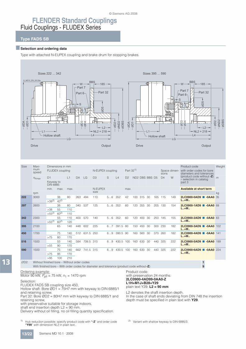
FLENDER Standard CouplingsFluid Couplings - FLUDEX Series
Type FADS SB
13/22 Siemens MD 10.1 · 2008
13
n Selection and ordering data
Type with attached N-EUPEX coupling and brake drum for stopping brakes.
Ordering example:Motor 90 kW, Peff = 75 kW, n1 = 1470 rpm
Selection: FLUDEX FADS SB coupling size 450, Hollow shaft: Bore ØD1 = 75H7 mm with keyway to DIN 6885/1 and retaining screw, Part 32: Bore ØD2 = 80H7 mm with keyway to DIN 6885/1 and retaining screw, with preservative suitable for storage indoors,shaft end insertion depth L2 = 90 mm.Delivery without oil filling, no oil filling quantity specification.
Product code:with preservation 24 months:2LC0900-4AD99-0AA0-ZL1H+M1J+B28+Y29plain text Y29: L2 = 90 mm
L2 denotes the shaft insertion depth.In the case of shaft ends deviating from DIN 748 the insertion depth must be specified in plain text with Y29.
L1 NL2 = 218
L2
185BBS
W
L4
LG
ØD
A
ØD
1
ØD
3Ø
D4
ØN
D2
ØD
2
ØD
BS
SØ
D5
ØD
A
ØD
1L1 NL2 = 218
L2
L4
LG
ØD
3Ø
D4
S
185BBS
W
ØD
5
ØN
D2
ØD
2
ØD
BS
Drive
Part 7
Part 6
Output
Hollow shaft
Part 32
G_MD10_EN_00128a
Sizes 222 ... 342
Drive Output
Hollow shaft
Part 32Part 7
Part 6
Sizes 395 ... 590
Size Maxi-mum speed
Dimensions in mm Product code Weight
FLUDEX coupling N-EUPEX coupling Part 321) Space dimen-sions
with order codes for bore diameters and tolerances (product code without -Z)– selection in catalog part 3
nKmax D1 L1 DA LG D3 S L4 D2 ND2 DBS BBS D5 D4 W m
Keyway to DIN 6885
min. max. max. N-EUPEX size
max. Available at short term
rpm kg
222 3000 38 80 263 494 110 5…6 352 42 100 315 30 165 115 149 2LC0900-0AD9L..+M..
n -0AA0 35
>382) 422)
297 2600 38 80 340 537 125 5…6 352 60 120 355 30 205 130 154 2LC0900-1AD9L..+M..
n -0AA0 68
>38 55 110
>552) 602) 110
342 2300 55 110 400 570 140 5…6 352 60 120 400 30 250 145 155 2LC0900-2AD9L..+M..
n -0AA0 83
>552) 602) 120
395 2100 65 140 448 602 225 6…7 391.5 80 150 450 30 300 230 182 2LC0900-3AD9L..+M..
n -0AA0 102
450 1700 75 140 512 631.5 250 8…9 390.5 90 160 560 30 370 260 182 2LC0900-4AD9L..+M..
n -0AA0 141
>75 80 170
516 1500 55 140 584 706.5 315 8…9 430.5 100 160 630 30 440 325 222 2LC0900-5AD9L..+M..
n -0AA0 199
>55 90 170
590 1500 75 140 662 741.5 315 8…9 430.5 100 160 630 30 440 325 222 2LC0900-6AD9L..+M..
n -0AA0 224
>75 95 170
>95 100 210
'D2: Without finished bore – Without order codes 1
With finished bore – With order codes for diameter and tolerance (product code without -Z) 9
1) Hub reduction possible; specify product code with “-Z” and order code “Y99” with dimension NL2 in plain text..
2) Variant with shallow keyway to DIN 6885/3.
© Siemens AG 2008

FLENDER Standard CouplingsFluid Couplings - FLUDEX Series
Type FADS HB
13/23Siemens MD 10.1 · 2008
13
n Selection and ordering data
Type with attached N-EUPEX coupling and brake disk for blocking brakes.
L2 denotes the shaft insertion depth.In the case of shaft ends deviating from DIN 748 the insertion depth must be specified in plain text with Y29.
For ordering example, see page 13/25.
ØD
A
ØD
1
ØD
2
ØD
1
ØD
2Ø
ND
2Ø
DB
S
ØN
D2
ØD
3
ØD
4
ØD
3Ø
D4
ØD
BS
ØD
A
S
S
L2
115
BBS
W 115
BBS
W
L2
L4 L4L1LG
L1LG
Drive
Part 7 Part 6
Output
Hollow shaft Part 5
G_M
D1
0_E
N_0
01
29
a
Sizes 222 ... 342
Drive Output
Hollow shaft Part 5Part 7 Part 6
Sizes 395 ... 590
Part 8Part 8
Size Maxi-mum speed
Dimensions in mm Product code Weight
FLUDEX coupling N-EUPEX coupling Part 5/81) Space dimensions
with order codes for bore diameters and tolerances (product code without -Z)– selection in catalog part 3
nKmax D1 L1 DA LG D3 S L4 D2 ND2 DBS BBS D4 W m
Keyway to DIN 6885
min. max. max. N-EUPEX size
max. Available at short term
rpm kg
222 3600 38 80 263 366.5 110 5…6 224.5 42 70 250 12.5 115 109 2LC0900-0AE9L..+M..
n -0AA0 22
>382) 422)
297 3600 38 80 340 409.5 125 5…6 224.5 60 85 250 12.5 130 114 2LC0900-1AE9L..+M..
n -0AA0 33
>38 55 110
>552) 602) 110
342 3600 55 110 400 442.5 140 5…6 224.5 60 90 250 12.5 145 115 2LC0900-2AE9L..+M..
n -0AA0 45
>552) 602) 120
395 3000 65 140 448 478 225 6…7 267.5 80 150 355 16 230 142 2LC0900-3AE9L..+M..
n -0AA0 80
450 3000 75 140 512 546.5 250 8…9 306.5 90 160 355 16 260 182 2LC0900-4AE9L..+M..
n -0AA0 101
>75 80 170
516 2300 55 140 584 566.5 315 8…9 290.5 100 160 450 16 325 166 2LC0900-5AE9L..+M..
n -0AA0 154
>55 90 170
590 2000 75 140 662 601.5 315 8…9 290.5 100 160 450 16 325 166 2LC0900-6AE9L..+M..
n -0AA0 179
>75 95 170
>95 100 210
'D2: Without finished bore – Without order codes 1
With finished bore – With order codes for diameter and tolerance (product code without -Z) 9
1) Hub reduction possible; specify product code with “-Z” and order code “Y99” in plain text.
2) Variant with shallow keyway to DIN 6885/3.
© Siemens AG 2008

FLENDER Standard CouplingsFluid Couplings - FLUDEX Series
Oil filling quantities for FA series
13/24 Siemens MD 10.1 · 2008
13
n Selection and ordering data
This assignment is valid for a maximum starting torque Tmax = 2.0 x Teff and mineral oils with a viscosity of VG 22/VG 32, with drive via the hollow shaft.
If other operating fluids are used, or with drive via the housing or Tmax 2.0 x Teff, changed filling quantities must be observed!
Ordering example type FAR from page 13/17:
Motor 45 kW, Peff = 37 kW, n1 = 1470 rpm, maximum output torque: Tmax = 2.0 x Teff.
Selection:FLUDEX FAR coupling size 395, Hollow shaft: Bore ØD1 = 60H7 mm with keyway to DIN 6885/1 and retaining screw. Specification of oil filling quantity: 7.6 l (see under oil filling quan-tities for the FA series in this catalog section).
Product code:
• With pulley 5xSPB224: 2LC0900-3AF90-0AA0-ZL1E+Y90plain text to Y90: 7.6 l
• With pulley 7xSPB236:2LC0900-3AF91-0AA0-ZL1E+Y90plain text toY90: 7.6 l
• With 160°C fuse: 2LC0900-3AF90-0AA0-ZL1E+Y90+F08plain text to Y90: 7.6 l
Ordering example type FADB from page 13/21:
Motor 30 kW, Peff = 22 kW, n1 = 1470 rpm
Selection: FLUDEX FADB coupling size 342, standard type, Hollow shaft: Bore ØD1 = 55H7 mm with keyway to DIN 6885/1 and retaining screw, Part 13: Bore ØD2 = 50H7 mm with keyway to DIN 6885/1 and set screw, shaft end insertion depth L2 = 90 mm.Delivery without oil filling, no oil filling quantity specification.
Product code:
• Part 13: Standard brake drum2LC0900-2AC99-0AA0-ZL1D+M1C+Y29plain text to Y29: 90 mm
• Part 13: Long brake drum2LC0900-2AC99-0BA0-ZL1D+M1C+Y29plain text to Y29: 90 mm
Peff Speed in rpm Size
600 740 890 980 1180 1470 1770 2300 2950 3550
kW Oil filling quantity in l
0.55 4.3 1.5 1.4 1.3 1.1
0.75 4.7 1.65 1.5 1.4 1.2
1.1 5.1 4.4 1.65 1.6 1.4 1.1
2.2 6.2 5.2 4.5 4.2 1.6 1.4 1.2
3.0 9.5 5.6 4.9 4.6 1.65 1.5 1.3 1.0
4.0 10.2 6.1 5.3 4.9 4.3 1.6 1.4 1.1
5.5 11.0 9.4 5.7 5.3 4.6 1.65 1.5 1.2 1.0
7.5 12.0 10.2 6.2 5.8 5.0 4.3 1.6 1.3 1.1
11 13.4 11.2 9.7 6.4 5.5 4.7 4.1 1.5 1.2 1.0 222
15 24.8 12.2 10.5 9.8 6.0 5.0 4.4 1.6 1.3 1.1
18 25.9 12.9 11.0 10.3 6.3 5.3 4.6 3.9 1.4 1.2
22 27.3 23.3 11.6 10.8 9.4 5.5 4.8 4.0 1.4 1.25
30 29.7 25.2 12.7 11.7 10.1 6.0 5.2 4.3 3.7 1.4
37 31.5 26.5 23.1 12.4 10.7 9.1 5.5 4.5 3.9 1.5
45 27.9 24.2 22.6 11.2 9.5 5.8 4.7 4.0 3.5 342
55 29.5 25.5 23.7 11.9 10.0 8.8 5.0 4.2 3.7
75 27.6 25.7 22.3 10.8 9.4 5.4 4.5 3.9
90 29.0 26.9 23.4 11.3 9.8 8.1 4.7 4.1
110 28.3 24.5 12.0 10.4 8.6 4.9 4.3
132 29.7 25.7 21.9 10.8 8.9 7.6 4.5
160 27.0 22.9 20.0 9.3 7.8 450
180 27.8 23.5 20.6 10.0 8.0
200 28.6 24.2 21.2 10.9 8.2
225 24.9 21.8 11.5 8.5
250 25.6 22.3 9.6
280 26.3 22.9 9.9
315 27.1 23.6 10.5
350 24.2 590
400 26.4
© Siemens AG 2008

FLENDER Standard CouplingsFluid Couplings - FLUDEX Series
Oil filling quantities for FA series
13/25Siemens MD 10.1 · 2008
13
Ordering example type FADS HB from page 13/23:
Motor 160 kW, Peff = 132 kW, n1 = 2950 rpm
Selection: FLUDEX FADS HB coupling size 395, Hollow shaft: Bore ØD1 = 65H7 mm with keyway to DIN 6885/1 and retaining screw, Part 5: Bore ØD2 = 80H7 mm with keyway to DIN 6885/1 and set screw, Fitting position: horizontal/vertical, motor overhead (MO)/motor underneath (MU),shaft insertion depth L2 = 80 mm.Delivery without oil filling, no oil filling quantity specification.
Product code:
• Horizontal version:2LC0900-3AE99-0AA0-ZL1F+M1J+Y29plain text to Y29: 80 mm
• Vertical version MO:2LC0900-3AE99-0AA0-ZL1F+M1J+F13+Y29plain text to Y29: 80 mm
• Vertical version MU:2LC0900-3AE99-0AA0-ZL1F+M1J+F14+Y29plain text to Y29: 80 mm
Peff Speed in rpm Size
600 740 890 980 1180 1470 1770 2300 2950 3550
kW Oil filling quantity in l
0.55 3.2 2.8
0.75 3.5 3.0 2.6
1.1 3.9 3.3 2.9 2.7
2.2 7.3 4.0 3.4 3.2 2.8
3.0 7.9 6.8 3.7 3.4 3.0 2.5
4.0 8.5 7.3 4.0 3.7 3.2 2.7
5.5 9.4 7.9 6.8 4.1 3.5 2.9 2.6
7.5 17.0 8.5 7.4 6.9 3.8 3.2 2.8 2.4
11 18.7 16.0 8.1 7.6 6.6 3.5 3.0 2.5
15 20.3 17.3 8.9 8.2 7.1 3.8 3.3 2.7
18 21.4 18.0 15.7 8.6 7.4 4.0 3.4 2.8 2.4
22 19.0 16.5 15.4 7.8 6.6 3.6 3.0 2.5
30 20.6 17.8 16.6 8.5 7.2 6.3 3.2 2.7 2.4 297
37 18.8 17.5 15.2 7.6 6.6 3.4 2.8 2.5
45 19.8 18.4 16.0 7.9 6.9 3.6 2.9 2.6
55 21.0 19.3 16.8 8.4 7.3 6.0 3.1 2.7
75 21.1 18.1 15.4 7.9 6.5 5.3 2.9
90 19.0 16.1 14.1 6.7 5.6 3.0
110 20.1 16.9 14.8 7.1 5.9 395
132 17.7 15.4 7.9 6.2
160 18.6 16.2 13.4 6.8
180 19.2 16.7 13.8 7.2
200 17.1 14.1 516
225 17.6 14.6
250 18.1 14.9
280 15.3
315 15.8
350 17.1
© Siemens AG 2008
FLENDER Standard CouplingsFluid Couplings - FLUDEX Series
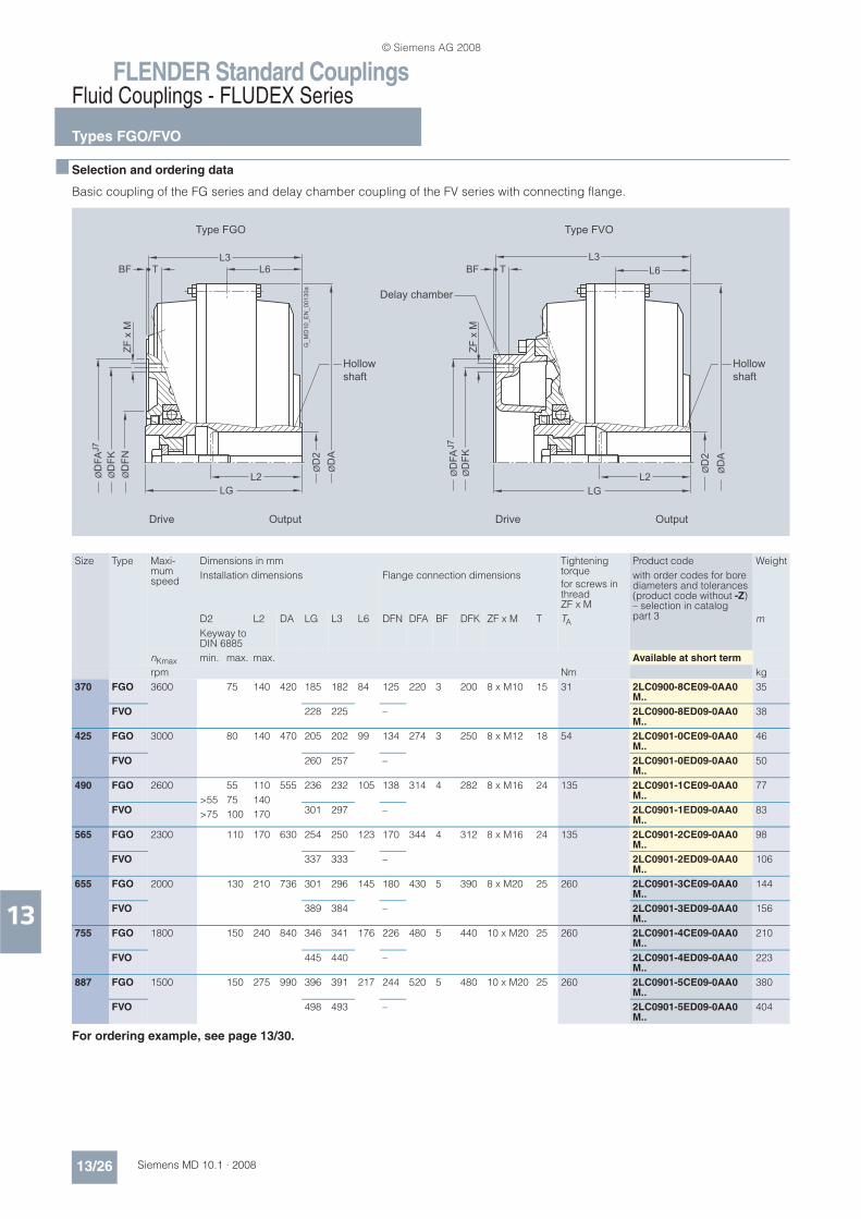
Types FGO/FVO
13/26 Siemens MD 10.1 · 2008
13
n Selection and ordering data
Basic coupling of the FG series and delay chamber coupling of the FV series with connecting flange.
For ordering example, see page 13/30.
ØD
FN
ZF
x M
ZF
x M
ØD
FK
ØD
A
ØD
2
ØD
FA
J7
ØD
2
ØD
A
ØD
FK
ØD
FA
J7
L6TBF TBFL3
L2 L2
L6
L3
LGLG
Type FGO
Drive Output
Hollow
shaft
G_M
D10
_E
N_00130a
Type FVO
Drive Output
Delay chamber
Hollow
shaft
Size Type Maxi-mum speed
Dimensions in mm Tightening torque
for screws in thread ZF x M
Product code Weight
Installation dimensions Flange connection dimensions with order codes for bore diameters and tolerances (product code without -Z)– selection in catalog part 3D2 L2 DA LG L3 L6 DFN DFA BF DFK ZF x M T TA m
Keyway to DIN 6885
nKmax min. max. max. Available at short term
rpm Nm kg
370 FGO 3600 75 140 420 185 182 84 125 220 3 200 8 x M10 15 31 2LC0900-8CE09-0AA0M..
35
FVO 228 225 – 2LC0900-8ED09-0AA0M..
38
425 FGO 3000 80 140 470 205 202 99 134 274 3 250 8 x M12 18 54 2LC0901-0CE09-0AA0M..
46
FVO 260 257 – 2LC0901-0ED09-0AA0M..
50
490 FGO 2600 55 110 555 236 232 105 138 314 4 282 8 x M16 24 135 2LC0901-1CE09-0AA0M..
77
>55 75 140FVO 301 297 – 2LC0901-1ED09-0AA0
M..83>75 100 170
565 FGO 2300 110 170 630 254 250 123 170 344 4 312 8 x M16 24 135 2LC0901-2CE09-0AA0M..
98
FVO 337 333 – 2LC0901-2ED09-0AA0M..
106
655 FGO 2000 130 210 736 301 296 145 180 430 5 390 8 x M20 25 260 2LC0901-3CE09-0AA0 M..
144
FVO 389 384 – 2LC0901-3ED09-0AA0 M..
156
755 FGO 1800 150 240 840 346 341 176 226 480 5 440 10 x M20 25 260 2LC0901-4CE09-0AA0 M..
210
FVO 445 440 – 2LC0901-4ED09-0AA0 M..
223
887 FGO 1500 150 275 990 396 391 217 244 520 5 480 10 x M20 25 260 2LC0901-5CE09-0AA0 M..
380
FVO 498 493 – 2LC0901-5ED09-0AA0 M..
404
© Siemens AG 2008

FLENDER Standard CouplingsFluid Couplings - FLUDEX Series
Types FGD/FVD
13/27Siemens MD 10.1 · 2008
13
n Selection and ordering data
Type with attached N-EUPEX D coupling. Enables change of flexible elements without axial displacement of the shafts if the space “A” is provided.
For ordering example, see page 13/31.
ØD
1
ØD
2
ØD
1
ØD
2
ØD
A
ØD
3
ØD
A
ØD
3
NL1L1 L2 L1 L2
LG
NL1
SS
AA
LG
Drive Output
Type FGD
Hollow shaft
Part 2 Part 3
G_MD10_EN_00131a
Drive Output
Type FVD
Hollow shaft
Part 2 Part 3
Delay
chamber
Size Type Maxi-mum speed
Dimensions in mm Product code Weight
FLUDEX coupling N–EUPEX D coupling with order codes for bore diameters and tolerances (product code without -Z)– selection in catalog part 3
D2 L2 DA LG D1 L1 NL1 D3 S A m
Keyway to DIN 6885
nKmax min. max. max. max. max. N-EUPEX size
Available at short term
rpm kg
370 FGD 3600 75 140 420 298 65 110 70 180 2…6 10 2LC0900-8CAL..+M..
n 9-0AA0 46
FVD 341 150 2LC0900-8EAL..+M..
n 9-0AA0 49
425 FGD 3000 80 140 470 348 85 140 90 225 2…6 9 2LC0901-0CAL..+M..
n 9-0AA0 66
FVD 403 195 2LC0901-0EAL..+M..
n 9-0AA0 70
490 FGD 2600 55 110 555 397 95 158 100 250 3…8 11 2LC0901-1CAL..+M..
n 9-0AA0 106
>55 75 140FVD 462 220 2LC0901-1EA
L..+M..n 9-0AA0 112>75 100 170
565 FGD 2300 110 170 630 430 105 170 110 280 3…8 5 2LC0901-2CAL..+M..
n 9-0AA0 134
FVD 513 255 2LC0901-2EAL..+M..
n 9-0AA0 142
655 FGD 2000 130 210 736 515 140 210 140 350 3…8 0 2LC0901-3CAL..+M..
n 9-0AA0 214
FVD 603 295 2LC0901-3EAL..+M..
n 9-0AA0 225
755 FGD 1800 150 240 840 584 150 230 160 400 3…8 0 2LC0901-4CAL..+M..
n 9-0AA0 302
FVD 683 330 2LC0901-4EAL..+M..
n 9-0AA0 316
887 FGD 1500 150 275 990 665 160 260 180 440 5…10 0 2LC0901-5CAL..+M..
n 9-0AA0 502
FVD 767 365 2LC0901-5EAL..+M..
n 9-0AA0 526
'D1: Without finished bore from size 655 with small hub for:
• Size 655 ØD1max = 110 mm
• Size 755 ØD1max = 120 mm
• Size 887 ØD1max = 130 mm – Without order code L..
1
Without finished bore from size 655 with large hub for:
• Size 655 ØD1 = 88 … 140
• Size 755 ØD1 = 98 … 150
• Size 887 ØD1 = 118 … 160 – Without order code L..
2
With finished bore – With order codes for diameter and tolerance (product code without -Z) 9
© Siemens AG 2008
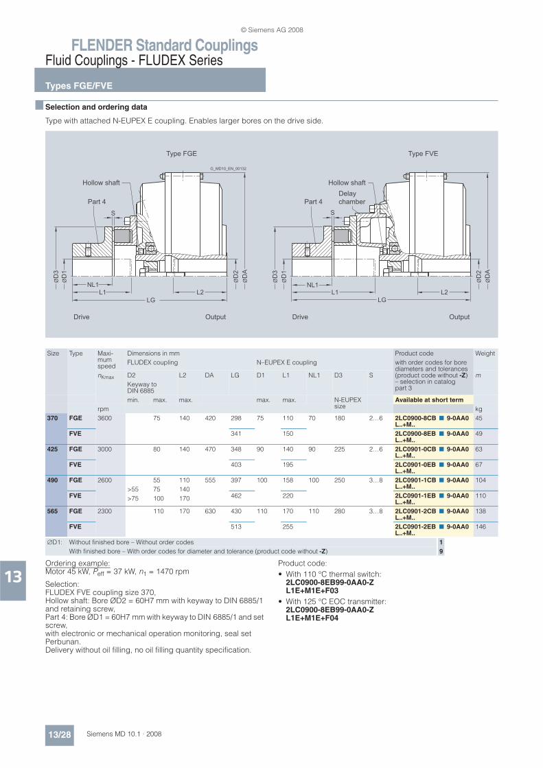
FLENDER Standard CouplingsFluid Couplings - FLUDEX Series
Types FGE/FVE
13/28 Siemens MD 10.1 · 2008
13
n Selection and ordering data
Type with attached N-EUPEX E coupling. Enables larger bores on the drive side.
Ordering example:Motor 45 kW, Peff = 37 kW, n1 = 1470 rpm
Selection: FLUDEX FVE coupling size 370, Hollow shaft: Bore ØD2 = 60H7 mm with keyway to DIN 6885/1 and retaining screw, Part 4: Bore ØD1 = 60H7 mm with keyway to DIN 6885/1 and set screw, with electronic or mechanical operation monitoring, seal set Perbunan.Delivery without oil filling, no oil filling quantity specification.
Product code:
• With 110 °C thermal switch:2LC0900-8EB99-0AA0-ZL1E+M1E+F03
• With 125 °C EOC transmitter:2LC0900-8EB99-0AA0-ZL1E+M1E+F04
ØD
1
ØD
2
ØD
1
ØD
2
ØD
A
ØD
3
ØD
A
ØD
3
NL1L1 L2 L1 L2
LG
NL1
SS
LG
Drive Output Drive Output
Type FGE
Hollow shaft
Part 4
G_MD10_EN_00132
Type FVE
Hollow shaft
Part 4
Delay
chamber
Size Type Maxi-mum speed
Dimensions in mm Product code Weight
FLUDEX coupling N–EUPEX E coupling with order codes for bore diameters and tolerances (product code without -Z)– selection in catalog part 3
nKmax D2 L2 DA LG D1 L1 NL1 D3 S m
Keyway to DIN 6885
min. max. max. max. max. N-EUPEX size
Available at short term
rpm kg
370 FGE 3600 75 140 420 298 75 110 70 180 2…6 2LC0900-8CBL..+M..
n 9-0AA0 45
FVE 341 150 2LC0900-8EBL..+M..
n 9-0AA0 49
425 FGE 3000 80 140 470 348 90 140 90 225 2…6 2LC0901-0CBL..+M..
n 9-0AA0 63
FVE 403 195 2LC0901-0EBL..+M..
n 9-0AA0 67
490 FGE 2600 55 110 555 397 100 158 100 250 3…8 2LC0901-1CBL..+M..
n 9-0AA0 104
>55 75 140FVE 462 220 2LC0901-1EB
L..+M..n 9-0AA0 110>75 100 170
565 FGE 2300 110 170 630 430 110 170 110 280 3…8 2LC0901-2CBL..+M..
n 9-0AA0 138
FVE 513 255 2LC0901-2EBL..+M..
n 9-0AA0 146
'D1: Without finished bore – Without order codes 1
With finished bore – With order codes for diameter and tolerance (product code without -Z) 9
© Siemens AG 2008

FLENDER Standard CouplingsFluid Couplings - FLUDEX Series
Types FGM/FVM
13/29Siemens MD 10.1 · 2008
13
n Selection and ordering data
Type with attached N-EUPEX M coupling. Enables a short fitting length.
Ordering example:Motor 45 kW, Peff = 37 kW, n1 = 1470 rpm
Selection: FLUDEX FGM coupling size 370, Hollow shaft: Bore ØD2 = 60H7 mm with keyway (for number of keyways, see “Special types”) to DIN 6885/1 and retaining screw, Part 4: Bore ØD1 = 60H7 mm with keyway to DIN 6885/1 and set screw.Delivery without oil filling, no oil filling quantity specification.
Product code:
• With one keyway:2LC0900-8CD99-0AA0L1E+M1E
• With two keyways set 180° apart:2LC0900-8CD99-0AA0-ZL1E+M1E+L46
• With two keyways set 120° apart:2LC0900-8CD99-0AA0-ZL1E+M1E+L47
ØD
1
ØD
2
ØD
1
ØD
2
ØD
A
ØD
3
ØD
A
ØD
3
NL1 L2
L1 L2
LG
NL1
SS
LG
Type FGM
Hollow shaft
Part 9
G_MD10_EN_00133
Drive Output
Drive Output
Type FVM
Hollow shaft
Part 9
Delay
chamber
Size Type Maxi-mum speed
Dimensions in mm Product code Weight
FLUDEX coupling N–EUPEX M coupling with order codes for bore diameters and tolerances (product code without -Z)– selection in catalog part 3
nKmax D2 L2 DA LG D1 L1 NL1 D3 S m
Keyway to DIN 6885
min. max. max. max. max. N-EUPEX size
Available at short term
rpm kg
370 FGM 3600 75 140 420 274 70 80 80 180 2…6 2LC0900-8CDL..+M..
n 9-0AA0 48
FVM 288 100 85 2LC0900-8ECL..+M..
n 9-0AA0 51
425 FGM 3000 80 140 470 310 85 100 100 225 2…6 2LC0901-0CDL..+M..
n 9-0AA0 67
FVM 327 120 100 2LC0901-0ECL..+M..
n 9-0AA0 71
490 FGM 2600 55 110 555 350 90 105 105 250 3…8 2LC0901-1CDL..+M..
n 9-0AA0 105
FVM >55 75 140 382 140 110 2LC0901-1ECL..+M..
n 9-0AA0 112
>75 100 170
565 FGM 2300 110 170 630 380 100 120 120 280 3…8 2LC0901-2CDL..+M..
n 9-0AA0 134
FVM 425 165 130 2LC0901-2ECL..+M..
n 9-0AA0 142
'D1: Without finished bore – Without order codes 1
With finished bore – With order codes for diameter and tolerance (product code without -Z) 9
© Siemens AG 2008

FLENDER Standard CouplingsFluid Couplings - FLUDEX Series
Oil filling quantities for FG/FV series
13/30 Siemens MD 10.1 · 2008
13
n Selection and ordering data
This assignment is valid for a maximum starting torque Tmax = 2.0 x Teff (FG series) or Tmax = 1.5 x Teff (FV series), and mineral oils with a viscosity of VG 22/VG 32.
If other operating fluids are used, or with drive via the hollow shaft or Tmax 2.0 x Teff or Tmax 1.5 x Teff, changed filling quantities must be observed!
Ordering example type FGO/FVO from page 13/26:
Motor 132 kW, Peff = 110 kW, n1 = 1470 rpm
Selection: FLUDEX FGO/FGV coupling size 490, Hollow shaft: Bore ØD2 = 70H7 mm with keyway to DIN 6885/1 and retaining screw. Delivery with oil filling: FGO = 14.4 l / FVO = 15.2 l (see under oil filling quantities for FG/FV series in this catalog section).
Product code:
• In type FGO:2LC0901-1CE09-0AA0-ZL1G+F16+Y90plain text to Y90: 14.4 l
• In type FGV:2LC0901-1ED09-0AA0-ZL1G+F16+Y90plain text to Y90: 15.2 l
Peff Speed in rpm Size
600 740 890 980 1180 1470 1770 2300 2950 3550
Series
FG FV FG FV FG FV FG FV FG FV FG FV FG FV FG FV FG FV FG FV
kW Oil filling quantity in l
1.1 5.3
2.2 6.4 6.7 5.5
3.0 7.0 7.4 5.9 6.1 5.0
4.0 7.2 8.0 6.4 6.6 5.6 5.0
5.5 13.0 13.8 6.9 7.4 6.0 6.2 5.6
7.5 14.4 15.2 7.2 8.0 6.5 6.8 6.0 6.2 5.1
11 15.9 17.4 13.3 14.1 7.2 7.7 6.7 7.1 5.7 5.9
15 17.0 18.5 14.7 15.6 12.4 13.0 7.2 7.7 6.2 6.5 5.2
18 17.0 31.6 15.4 16.6 13.1 13.8 12.0 12.5 6.5 6.9 5.5
22 31.1 33.2 16.2 17.7 14.0 14.8 12.7 13.4 6.9 7.3 5.7 5.9 4.8
30 35.9 36.5 17.0 18.5 15.2 16.3 14.1 14.9 11.8 12.3 6.3 6.5 5.3 5.5
37 37.9 39.9 29.9 32.4 16.1 17.5 14.9 15.9 12.6 13.3 6.6 7.0 5.7 5.9 4.2
45 39.7 44.0 32.3 34.0 17.0 18.5 15.7 17.0 13.4 14.1 7.0 7.5 6.0 6.2 4.6
55 40.0 44.0 35.5 36.2 28.4 31.0 16.6 18.1 14.3 15.1 11.6 12.0 6.4 6.7 5.0 5.1
75 70.5 75.8 38.7 41.4 31.7 33.6 28.5 31.2 15.5 16.7 12.7 13.5 6.9 7.4 5.5 5.7 4.3 4.2
90 74.7 80.0 40.0 44.0 34.4 35.4 30.4 32.7 16.3 17.7 13.5 14.3 11.4 11.6 5.9 6.1 4.6 4.5
110 81.0 84.3 40.0 44.0 37.0 38.2 33.0 34.5 27.3 29.9 14.4 15.2 12.1 12.6 6.2 6.4 4.9 5.0 4.0 4.1 370
132 88.2 89.2 69.3 74.6 38.8 41.6 36.0 36.7 28.6 31.3 15.1 16.2 12.8 13.5 6.5 6.9 5.2 5.4 4.4 4.2
160 93.5 96.3 73.3 78.7 40.0 44.0 37.8 39.8 30.6 32.9 15.9 17.3 13.6 14.4 10.6 10.4 5.5 5.7 4.7 4.6
180 96.4 101.8 76.5 81.3 65.4 44.0 38.9 42.1 32.1 33.9 26.2 17.9 14.1 14.9 11.0 11.0 5.8 6.0 4.9 4.9
200 98.0 107.0 79.8 83.6 67.0 72.1 39.9 44.0 33.7 34.9 26.9 29.4 14.6 15.4 11.4 11.7 6.0 6.2 5.0 5.1
250 98.0 107.0 88.7 89.5 70.9 76.3 40.0 44.0 36.8 37.9 28.4 31.1 15.4 16.7 12.2 12.8 5.4 5.5
315 84.7 98.5 76.6 81.5 69.8 75.6 39.0 42.1 30.8 33.0 26.2 28.6 13.1 13.9 490
350 97.2 103.6 80.0 83.7 71.8 77.7 39.9 44.0 32.2 33.9 26.9 29.5 13.6 14.4
400 98.0 107.0 85.1 86.9 75.2 80.5 64.5 68.4 34.2 35.3 27.8 30.4 655
500 98.0 107.0 92.4 94.5 82.5 85.3 68.1 73.8 37.1 38.4 29.7 32.3
600 96.9 102.9 90.1 90.6 71.5 77.3 38.8 41.8 31.9 33.8
750 98.0 107.0 95.3 99.6 77.3 81.9 64.0 67.8 35.4 36.2
900 98.0 107.0 83.7 86.0 67.0 72.7 887
1100 81.1 92.3 70.4 76.2
1300 95.2 99.3 74.2 79.8
1600 80.6 84.0
© Siemens AG 2008

FLENDER Standard CouplingsFluid Couplings - FLUDEX Series
Oil filling quantities for FG/FV series
13/31Siemens MD 10.1 · 2008
13
Ordering example type FGD from page 13/27:
Motor 350 kW, Peff = 315 kW, n1 = 1470 rpm
Selection: FLUDEX FGD coupling size 655, standard type, Hollow shaft: Bore ØD2 = 120H7 mm with keyway to DIN 6885/1 and retaining screw, Part 2: Bore ØD1 = see ordering data table “Without finished bore” and “With finished bore”, keyway to DIN 6885/1 and set screw.Delivery without oil filling, no oil filling quantity specification.
Product code:
• Without finished bore for ØD1 = 110 mm:2LC0901-3CA19-0AA0L1S
• Without finished bore for ØD1 = 130 mm:2LC0901-3CA29-0AA0L1S
• With finished bore for ØD1 = 140H7 mm:2LC0901-3CA99-0AA0L1S+M1V
Peff Speed in rpm Size
600 740 890 980 1180 1470 1770 2300 2950 3550
Series
FG FV FG FV FG FV FG FV FG FV FG FV FG FV FG FV FG FV FG FV
kW Oil filling quantity in l
3.0 8.7 9.1
4.0 9.5 9.9 8.1
5.5 10.3 11.1 8.7 9.0
7.5 10.9 12.0 9.5 9.9 8.3 7.4
11 19.9 21.4 10.5 11.3 9.1 9.4 8.6
15 22.0 23.7 10.9 12.0 9.8 10.4 9.1 9.5 7.8
18 23.2 25.2 19.1 20.5 10.3 11.1 9.6 10.1 8.4
22 24.3 27.0 20.3 21.9 10.9 11.7 10.1 10.8 8.6 9.0
30 42.0 45.0 22.4 24.2 18.9 20.1 10.9 11.8 9.5 9.9 7.9
37 44.4 47.5 23.7 26.0 20.1 21.7 18.5 19.5 10.0 10.7 8.2 8.6 6.7
45 47.7 50.0 24.9 27.7 21.5 23.1 19.5 21.0 10.5 11.3 8.8 9.2 7.5
55 52.0 53.0 25.5 28.0 22.8 24.6 20.8 22.5 17.5 18.3 9.3 9.7 7.8 8.1
75 58.0 59.5 45.6 48.5 24.6 27.4 22.9 24.8 19.3 20.7 10.1 10.8 8.6 9.0 6.5
90 60.5 65.5 49.1 50.5 25.5 28.9 23.9 26.5 20.4 22.0 10.7 11.4 9.2 9.5 7.2 7.1
110 61.0 67.0 54.0 54.0 43.2 46.4 25.5 28.0 21.8 23.4 17.7 18.7 9.7 10.2 7.6 7.8
132 57.0 58.0 45.8 48.7 42.1 45.1 23.0 24.9 18.7 19.9 10.1 10.9 8.1 8.4 6.3 6.1 425
160 60.0 63.5 49.5 51.0 44.3 47.4 24.0 26.7 19.8 21.4 16.7 16.8 8.6 8.9 6.8 6.6
180 61.5 67.0 52.3 53.0 46.2 49.0 24.8 27.6 20.6 22.2 17.3 18.0 8.8 9.3 7.0 6.9
200 62.5 67.0 55.0 55.0 48.1 50.0 25.5 43.7 21.4 23.0 17.9 18.9 9.2 9.6 7.3 7.3
250 58.5 60.5 53.5 53.5 42.9 46.0 22.8 24.7 19.2 20.6 14.6 14.7 7.8 8.0
315 61.0 67.0 57.5 58.5 46.2 49.0 24.2 26.8 20.6 22.3 16.1 16.1 8.3 8.7
350 62.5 67.0 59.0 61.5 48.2 50.0 39.7 42.4 21.4 23.0 16.7 16.8 565
400 61.0 66.0 51.0 52.0 41.0 44.0 22.2 24.0 17.4 18.1
500 61.0 67.0 56.0 56.5 43.3 46.5 37.8 40.0 18.7 19.9
600 59.0 61.0 46.0 49.0 39.5 42.1 21.2
750 50.5 51.5 41.7 45.0 755
900 55.5 55.0 43.7 47.0
1100 46.8 49.5
© Siemens AG 2008

FLENDER Standard CouplingsFluid Couplings - FLUDEX Series
Type FNO
13/32 Siemens MD 10.1 · 2008
13
n Selection and ordering data
Type with large delay chamber and connecting shaft.
For ordering example, see page 13/39.
ØD
1
ØD
Wm
6
ØD
A
NL1
L1 LW
LG
L7
Hub long
Hub standard
DIN 6885/1
Shaft
Hub carrier
(Delay chamber)
Drive Output
G_M
D10
_E
N_00134
Size Maximum speed
Hub carrier
Dimensions in mm Product code Weight
Installation dimensions Connection dimensions
with order codes for bore diameters and tolerances (product code without -Z)– selection in catalog part 3
nKmax D1 L1 NL1 DA LG L7 DW LW m
Keyway to DIN 6885
min. max. max. Available at short term
rpm Hub kg
370 3600 Standard 38 55 110 115 420 380 101 60 70 2LC0900-8GAL..
n 0-1AA0 56
Long 38 80 140 145 420 410 2LC0900-8GAL..
n 0-2AA0 54
425 3000 Standard 42 75 140 147 470 437 106 70 80 2LC0901-0GAL..
n 0-1AA0 77
Long 42 100 170 177 470 467 2LC0901-0GAL..
n 0-2AA0 74
490 2600 Standard 48 75 140 148 555 485 131 70 90 2LC0901-1GAL..
n 0-1AA0 120
Long 48 110 170 178 555 515 2LC0901-1GAL..
n 0-2AA0 115
565 2300 Standard 65 95 170 178 630 543 131 90 100 2LC0901-2GAL..
n 0-1AA0 161
Long 65 120 210 218 630 583 2LC0901-2GAL..
n 0-2AA0 159
655 2000 Standard 65 120 210 218 736 644 156 100 125 2LC0901-3GAL..
n 0-1AA0 233
Long 65 135 250 258 736 684 2LC0901-3GAL..
n 0-2AA0 232
755 1800 Standard 65 120 210 219 840 705 170 110 140 2LC0901-4GAL..
n 0-1AA0 309
Long 65 150 250 259 840 745 2LC0901-4GAL..
n 0-2AA0 307
887 1500 Standard 65 150 250 251 990 835 187 120 178 2LC0901-5GAL..
n 0-1AA0 541
Long 65 170 300 301 990 885 2LC0901-5GAL..
n 0-2AA0 544
'D1: Without finished bore – Without order codes 1
With finished bore – With order codes for diameter and tolerance (product code without -Z) 9
© Siemens AG 2008
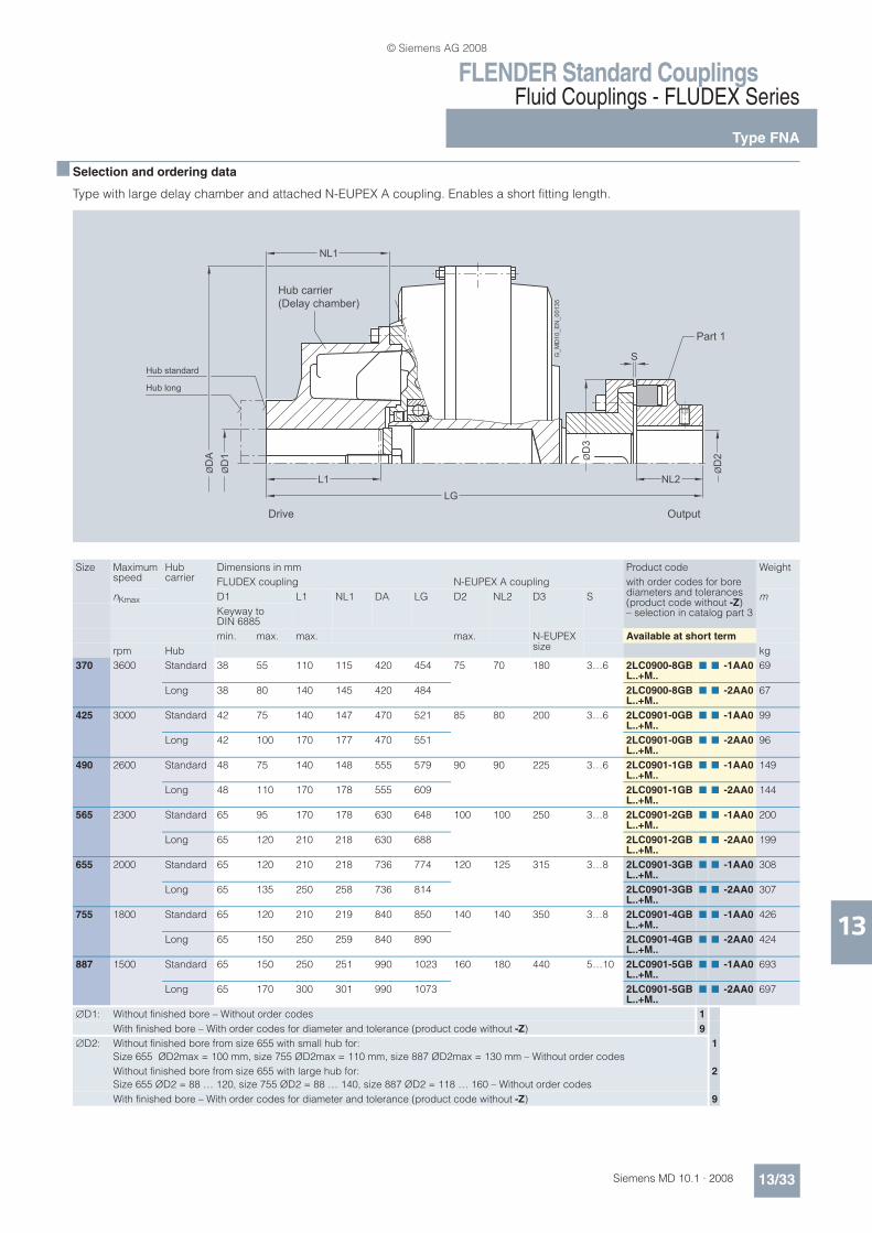
FLENDER Standard CouplingsFluid Couplings - FLUDEX Series
Type FNA
13/33Siemens MD 10.1 · 2008
13
n Selection and ordering data
Type with large delay chamber and attached N-EUPEX A coupling. Enables a short fitting length.
ØD
1 ØD
3
ØD
2
ØD
A
NL1
L1 NL2
S
LG
Hub long
Hub standard
Part 1
Hub carrier
(Delay chamber)
Drive Output
G_M
D10
_E
N_00135
Size Maximum speed
Hub carrier
Dimensions in mm Product code Weight
FLUDEX coupling N-EUPEX A coupling with order codes for bore diameters and tolerances (product code without -Z)– selection in catalog part 3
nKmax D1 L1 NL1 DA LG D2 NL2 D3 S m
Keyway to DIN 6885
min. max. max. max. N-EUPEX size
Available at short term
rpm Hub kg
370 3600 Standard 38 55 110 115 420 454 75 70 180 3…6 2LC0900-8GBL..+M..
n n -1AA0 69
Long 38 80 140 145 420 484 2LC0900-8GBL..+M..
n n -2AA0 67
425 3000 Standard 42 75 140 147 470 521 85 80 200 3…6 2LC0901-0GBL..+M..
n n -1AA0 99
Long 42 100 170 177 470 551 2LC0901-0GBL..+M..
n n -2AA0 96
490 2600 Standard 48 75 140 148 555 579 90 90 225 3…6 2LC0901-1GBL..+M..
n n -1AA0 149
Long 48 110 170 178 555 609 2LC0901-1GBL..+M..
n n -2AA0 144
565 2300 Standard 65 95 170 178 630 648 100 100 250 3…8 2LC0901-2GBL..+M..
n n -1AA0 200
Long 65 120 210 218 630 688 2LC0901-2GBL..+M..
n n -2AA0 199
655 2000 Standard 65 120 210 218 736 774 120 125 315 3…8 2LC0901-3GBL..+M..
n n -1AA0 308
Long 65 135 250 258 736 814 2LC0901-3GBL..+M..
n n -2AA0 307
755 1800 Standard 65 120 210 219 840 850 140 140 350 3…8 2LC0901-4GBL..+M..
n n -1AA0 426
Long 65 150 250 259 840 890 2LC0901-4GBL..+M..
n n -2AA0 424
887 1500 Standard 65 150 250 251 990 1023 160 180 440 5…10 2LC0901-5GBL..+M..
n n -1AA0 693
Long 65 170 300 301 990 1073 2LC0901-5GBL..+M..
n n -2AA0 697
'D1: Without finished bore – Without order codes 1
With finished bore – With order codes for diameter and tolerance (product code without -Z) 9
'D2: Without finished bore from size 655 with small hub for:
Size 655 ØD2max = 100 mm, size 755 ØD2max = 110 mm, size 887 ØD2max = 130 mm – Without order codes
1
Without finished bore from size 655 with large hub for:
Size 655 ØD2 = 88 … 120, size 755 ØD2 = 88 … 140, size 887 ØD2 = 118 … 160 – Without order codes
2
With finished bore – With order codes for diameter and tolerance (product code without -Z) 9
© Siemens AG 2008

FLENDER Standard CouplingsFluid Couplings - FLUDEX Series
Type FND
13/34 Siemens MD 10.1 · 2008
13
n Selection and ordering data
Type with large delay chamber and attached N-EUPEX D coupling.Enables fitting and dismounting of the coupling without displacement of the coupled shafts.
For ordering example, see page 13/39.
ØD
1 ØD
3
ØD
2
ØD
A
NL1
L1 NL2
S
LG
Hub long
Hub standard Part 11
Hub carrier
(Delay chamber)
Drive OutputG
_M
D10
_E
N_00136
Size Maximum speed
Hub carrier
Dimensions in mm Product code Weight
FLUDEX coupling N–EUPEX D coupling with order codes for bore diameters and tolerances (product code without -Z)– selection in catalog part 3
nKmax D1 L1 NL1 DA LG D2 NL2 D3 S m
Keyway to DIN 6885
min max. max. max. N-EUPEX size
Available at short term
rpm Hub kg
370 3600 Standard 38 55 110 115 420 494 70 70 180 4…6 2LC0900-8GCL..+M..
n n -1AA0 74
Long 38 80 140 145 420 524 2LC0900-8GCL..+M..
n n -2AA0 72
425 3000 Standard 42 75 140 147 470 566 80 80 200 4…6 2LC0901-0GCL..+M..
n n -1AA0 101
Long 42 100 170 177 470 596 2LC0901-0GCL..+M..0
n n -2AA 99
490 2600 Standard 48 75 140 148 555 629 90 90 225 4…6 2LC0901-1GCL..+M..
n n -1AA0 153
Long 48 110 170 178 555 659 2LC0901-1GCL..+M..
n n -2AA0 149
565 2300 Standard 65 95 170 178 630 706 100 100 250 5…8 2LC0901-2GCL..+M..
n n -1AA0 207
Long 65 120 210 218 630 746 2LC0901-2GCL..+M..
n n -2AA0 206
655 2000 Standard 65 110 210 218 736 842 110 125 315 5…8 2LC0901-3GCL..+M..
n n -1AA0 315
Long 65 135 250 258 736 882 2LC0901-3GCL..+M..
n n -2AA0 314
755 1800 Standard 65 120 210 219 840 921 120 140 350 5…8 2LC0901-4GCL..+M..
n n -1AA0 433
Long 65 150 250 259 840 961 2LC0901-4GCL..+M..
n n -2AA0 431
887 1500 Standard 65 150 250 251 990 1104 130 180 440 5…10 2LC0901-5GCL..+M..
n n -1AA0 719
Long 65 170 300 301 990 1154 2LC0901-5GCL..+M..
n n -2AA0 723
'D1: Without finished bore – Without order codes 1
With finished bore – With order codes for diameter and tolerance (product code without -Z) 9
'D2: Without finished bore – Without order codes 1
With finished bore – With order codes for diameter and tolerance (product code without -Z) 9
© Siemens AG 2008
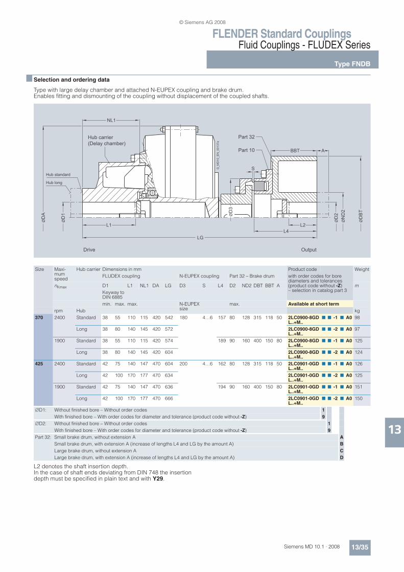
FLENDER Standard CouplingsFluid Couplings - FLUDEX Series
Type FNDB
13/35Siemens MD 10.1 · 2008
13
n Selection and ordering data
Type with large delay chamber and attached N-EUPEX coupling and brake drum.Enables fitting and dismounting of the coupling without displacement of the coupled shafts.
L2 denotes the shaft insertion depth.In the case of shaft ends deviating from DIN 748 the insertion depth must be specified in plain text and with Y29.
ØD
1 ØD
3
ØD
2
ØN
D2
ØD
BT
ØD
A
NL1
L1 L2
S
BBT A
LG
L4
Output
Hub long
Hub standard
Part 10
Part 32Hub carrier
(Delay chamber)
Drive
G_M
D10
_E
N_00137a
Size Maxi-mum speed
Hub carrier Dimensions in mm Product code Weight
FLUDEX coupling N-EUPEX coupling Part 32 – Brake drum with order codes for bore diameters and tolerances (product code without -Z)– selection in catalog part 3
nKmax D1 L1 NL1 DA LG D3 S L4 D2 ND2 DBT BBT A m
Keyway to DIN 6885
min. max. max. N-EUPEX size
max. Available at short term
rpm Hub kg
370 2400 Standard 38 55 110 115 420 542 180 4…6 157 80 128 315 118 50 2LC0900-8GDL..+M..
n n -1 n A0 98
Long 38 80 140 145 420 572 2LC0900-8GDL..+M..
n n -2 n A0 97
1900 Standard 38 55 110 115 420 574 189 90 160 400 150 80 2LC0900-8GDL..+M..
n n -1 n A0 125
Long 38 80 140 145 420 604 2LC0900-8GDL..+M..
n n -2 n A0 124
425 2400 Standard 42 75 140 147 470 604 200 4…6 162 80 128 315 118 50 2LC0901-0GDL..+M..
n n -1 n A0 126
Long 42 100 170 177 470 634 2LC0901-0GDL..+M..
n n -2 n A0 125
1900 Standard 42 75 140 147 470 636 194 90 160 400 150 80 2LC0901-0GDL..+M..
n n -1 n A0 151
Long 42 100 170 177 470 666 2LC0901-0GDL..+M..
n n -2 n A0 150
'D1: Without finished bore – Without order codes 1
With finished bore – With order codes for diameter and tolerance (product code without -Z) 9
'D2: Without finished bore – Without order codes 1
With finished bore – With order codes for diameter and tolerance (product code without -Z) 9
Part 32: Small brake drum, without extension A A
Small brake drum, with extension A (increase of lengths L4 and LG by the amount A) B
Large brake drum, without extension A C
Large brake drum, with extension A (increase of lengths L4 and LG by the amount A) D
© Siemens AG 2008
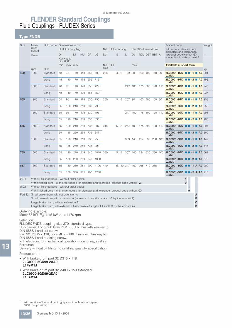
FLENDER Standard CouplingsFluid Couplings - FLUDEX Series
Type FNDB
13/36 Siemens MD 10.1 · 2008
13
Ordering example:Motor 55 kW, Peff = 45 kW, n1 = 1470 rpm
Selection: FLUDEX FNDB coupling size 370, standard type, Hub carrier: Long hub bore ØD1 = 65H7 mm with keyway to DIN 6885/1 and set screw, Part 32: Ø315 x 118, bore ØD2 = 80H7 mm with keyway to DIN 6885/1 and retaining screw, with electronic or mechanical operation monitoring, seal set Perbunan.Delivery without oil filling, no oil filling quantity specification.
Product code:
• With brake drum part 32 Ø315 x 118:2LC0900-8GD99-2AA0L1F+M1J
• With brake drum part 32 Ø400 x 150 extended:2LC0900-8GD99-2DA0L1F+M1J
Size Maxi-mum speed
Hub carrier Dimensions in mm Product code Weight
FLUDEX coupling N-EUPEX coupling Part 32 – Brake drum with order codes for bore diameters and tolerances (product code without -Z)– selection in catalog part 3
nKmax D1 L1 NL1 DA LG D3 S L4 D2 ND2 DBT BBT A m
Keyway to DIN 6885
min. max. max. N-EUPEX size
max. Available at short term
rpm Hub kg
490 1900 Standard 48 75 140 148 555 689 225 4…6 199 90 160 400 150 80 2LC0901-1GDL..+M..
n n -1 n A0 201
Long 48 110 170 178 555 719 2LC0901-1GDL..+M..
n n -2 n A0 198
15001) Standard 48 75 140 148 555 729 247 100 175 500 190 110 2LC0901-1GDL..+M..
n n -1 n A0 240
Long 48 110 170 178 555 759 2LC0901-1GDL..+M..
n n -2 n A0 237
565 1900 Standard 65 95 170 178 630 756 250 5…8 207 90 160 400 150 80 2LC0901-2GDL..+M..
n n -1 n A0 258
Long 65 120 210 218 630 796 2LC0901-2GDL..+M..
n n -2 n A0 256
15001) Standard 65 95 170 178 630 796 247 100 175 500 190 110 2LC0901-2GDL..+M..
n n -1 n A0 291
Long 65 120 210 218 630 836 2LC0901-2GDL..+M..
n n -2 n A0 293
655 15001) Standard 65 120 210 218 736 907 315 5…8 257 100 175 500 190 110 2LC0901-3GDL..+M..
n n -1 n A0 394
Long 65 135 250 258 736 947 2LC0901-3GDL..+M..
n n -2 n A0 390
1500 Standard 65 120 210 218 736 953 303 140 224 630 236 100 2LC0901-3GDL..+M..
n n -1 n A0 449
Long 65 135 250 258 736 993 2LC0901-3GDL..+M..
n n -2 n A0 445
755 1500 Standard 65 120 210 219 840 1018 350 5…8 307 140 224 630 236 100 2LC0901-4GDL..+M..
n n -1 n A0 569
Long 65 150 250 259 840 1058 2LC0901-4GDL..+M..
n n -2 n A0 572
887 1300 Standard 65 150 250 251 990 1190 440 5…10 347 160 265 710 265 - 2LC0901-5GDL..+M..
n n -1 A A0 902
Long 65 170 300 301 990 1240 2LC0901-5GDL..+M..
n n -2 A A0 915
'D1: Without finished bore – Without order codes 1
With finished bore – With order codes for diameter and tolerance (product code without -Z) 9
'D2: Without finished bore – Without order codes 1
With finished bore – With order codes for diameter and tolerance (product code without -Z) 9
Part 32: Small brake drum, without extension A A
Small brake drum, with extension A (increase of lengths L4 and LG by the amount A) B
Large brake drum, without extension A C
Large brake drum, with extension A (increase of lengths L4 and LG by the amount A) D
1) With version of brake drum in grey cast iron: Maximum speed 1800 rpm possible.
© Siemens AG 2008

FLENDER Standard CouplingsFluid Couplings - FLUDEX SeriesType FNDS SB with large delay chamber
and brake disk for stopping brake
13/37Siemens MD 10.1 · 2008
13
n Selection and ordering data
Type with large delay chamber, attached N-EUPEX coupling and brake disk for stopping brakes.Enables fitting and dismounting of the coupling without displacement of the coupled shafts.
L2 denotes the shaft insertion depth.In the case of shaft ends deviating from DIN 748 the insertion depth must be specified in plain text and with Y29.
For ordering example, see page 13/40.
1) Hub reduction possible; specify product code with “-Z” and order code “Y99” with dimension NL2 in plain text.
ØD
1
ØD
3
ØD
2
ØN
D2
ØD
BS
ØD
A
NL1
L1 L2
S
W 185BBS
ØD
4
ØD
5
LG
NL2 = 218
L4
Output
Hub long
Hub standard
Part 10
Part 32Hub carrier
(Delay chamber)
Drive
G_MD10_EN_00138a
Size Maxi-mum speed
Hub carrier
Dimensions in mm Product code Weight
FLUDEX coupling N-EUPEX coupling Part 32 – Brake disk1) Space dimen-sions
with order codes for bore diameters and tolerances (product code without -Z)– selection in catalog part 3
nKmax D1 L1 NL1 DA LG D3 S L4 D2 ND2 DBS BBS D5 D4 W m
Keyway to DIN 6885
min. max. max. N-EUPEX size
max. Available at short term
rpm Hub kg
370 2100 Standard 38 55 110 115 420 642 180 4…6 257 80 145 450 30 300 222 127 2LC0900-8GEL..+M..
n n -1CA0 109
Long 38 80 140 145 420 672 2LC0900-8GEL..+M..
n n -2CA0 108
425 1900 Standard 42 75 140 147 470 704 200 4…6 262 80 160 500 30 340 250 144 2LC0901-0GEL..+M..
n n -1BA0 161
Long 42 100 170 177 470 734 2LC0901-0GEL..+M..
n n -2BA0 159
490 1700 Standard 48 75 140 148 555 757 225 4…6 267 90 160 560 30 370 276 159 2LC0901-1GEL..+M..
n n -1BA0 214
Long 48 110 170 178 555 787 2LC0901-1GEL..+M..
n n -2BA0 211
565 1500 Standard 65 95 170 178 630 824 250 5…8 275 100 175 630 30 440 317 181 2LC0901-2GEL..+M..
n n -1BA0 290
Long 65 120 210 218 630 864 2LC0901-2GEL..+M..
n n -2BA0 291
655 1500 Standard 65 120 210 218 736 935 315 5…8 285 100 175 630 30 440 385 203 2LC0901-3GEL..+M..
n n -1AA0 382
Long 65 135 250 258 736 975 2LC0901-3GEL..+M..
n n -2AA0 385
755 1300 Standard 65 120 210 219 840 1000 350 5…8 289 140 220 710 30 520 435 222 2LC0901-4GEL..+M..
n n -1AA0 508
Long 65 150 250 259 840 1040 2LC0901-4GEL..+M..
n n -2AA0 511
887 1100 Standard 65 150 250 251 990 1144 440 5…10 301 140 220 800 30 610 525 268 2LC0901-5GEL..+M..
n n -1AA0 788
Long 65 170 300 301 990 1194 2LC0901-5GEL..+M..
n n -2AA0 801
'D1: Without finished bore – Without order codes 1
With finished bore – With order codes for diameter and tolerance (product code without -Z) 9
'D2: Without finished bore – Without order codes 1
With finished bore – With order codes for diameter and tolerance (product code without -Z) 9
© Siemens AG 2008

FLENDER Standard CouplingsFluid Couplings - FLUDEX SeriesType FNDS HB with large delay chamberand brake disk for blocking brake
13/38 Siemens MD 10.1 · 2008
13
n Selection and ordering data
Type with large delay chamber, attached N-EUPEX coupling and brake disk for blocking brakes.Enables fitting and dismounting of the coupling without displacement of the coupled shafts.
For ordering example, see page 13/40.
1) Hub reduction possible; specify product code with “-Z” and order code “Y99” with dimension L5 in plain text.
ØD
1
ØD
3
ØD
2
ØN
D2
ØD
BS
ØD
A
NL1
L1 NL2
S
W L5BBS
ØD
4LG
L4
Output
Hub long
Hub standard
Part 10
Part 11
Part 8
Drive
G_M
D10
_E
N_00139
Hub carrier
(Delay chamber)
Size Maxi-mum speed
Hub carrier
Dimensions in mm Product code Weight
FLUDEX coupling N-EUPEX coupling Part 8 – Brake disk/part 11 – hub
Space dimen-sions
with order codes for bore diameters and tolerances (product code without -Z)– selection in catalog part 3
nKmax D1 L1 NL1 DA LG D3 S L4 D2 NL2 ND2 DBS BBS L5 1)
D4 W
Keyway to DIN 6885
min. max. max. N-EUPEX size
max. Available at short term
rpm Hub kg
370 3200 Standard 38 55 110 115 420 555 180 4…6 170 80 118 130 355 16 115 222 127 2LC0900-8GFL..+M..
n n -1AA0 84
Long 38 80 140 145 420 585 2LC0900-8GFL..+M..
n n -2AA0 83
425 3000 Standard 42 75 140 147 470 617 200 4…6 175 80 118 130 355 16 115 250 144 2LC0901-0GFL..+M..
n n -1AA0 116
Long 42 100 170 177 470 647 2LC0901-0GFL..+M..
n n -2AA0 115
490 2600 Standard 48 75 140 148 555 670 225 4…6 180 90 118 135 400 16 115 276 159 2LC0901-1GFL..+M..
n n -1AA0 169
Long 48 110 170 178 555 700 2LC0901-1GFL..+M..
n n -2AA0 166
565 2300 Standard 65 95 170 178 630 737 250 5…8 188 100 118 160 450 16 115 317 181 2LC0901-2GFL..+M..
n n -1AA0 227
Long 65 120 210 218 630 777 2LC0901-2GFL..+M..
n n -2AA0 229
655 2000 Standard 65 110 210 218 736 848 315 5…8 198 100 118 170 500 16 115 385 203 2LC0901-3GFL..+M..
n n -1AA0 348
Long 65 135 250 258 736 888 2LC0901-3GFL..+M..
n n -2AA0 351
755 1800 Standard 65 120 210 219 840 961 350 5…8 250 140 164 225 630 20 160 435 222 2LC0901-4GFL..+M..
n n -1AA0 486
Long 65 150 250 259 840 1001 2LC0901-4GFL..+M..
n n -2AA0 489
887 1500 Standard 65 150 250 251 990 1105 440 5…10 262 140 164 225 710 20 160 525 268 2LC0901-5GFL..+M..
n n -1AA0 769
Long 65 170 300 301 990 1155 2LC0901-5GFL..+M..
n n -2AA0 782
'D1: Without finished bore – Without order codes 1
With finished bore – With order codes for diameter and tolerance (product code without -Z) 9
'D2: Without finished bore – Without order codes 1
With finished bore – With order codes for diameter and tolerance (product code without -Z) 9
© Siemens AG 2008

FLENDER Standard CouplingsFluid Couplings - FLUDEX Series
Oil filling quantities for FN series
13/39Siemens MD 10.1 · 2008
13
n Selection and ordering data
This assignment is valid for a maximum starting torque Tmax = 1.3 x Teff and mineral oils with a viscosity of VG 22/VG 32.
If other operating fluids are used, or with drive via the shaft or Tmax 1.3 x Teff, changed filling quantities must be observed!
Ordering example type FNO from page 13/32:
Motor 110 kW, Peff = 90 kW, n1 = 1470 rpm, maximum output torque Tmax = 1.3 x Teff
Selection: FLUDEX FNO coupling size 425, Hub carrier: Standard hub bore ØD1 = 75H7 mm with keyway to DIN 6885/1 and retaining screw, seal set Viton.Specification of oil filling quantity: 12.4 l (see under oil filling quantities for the FN series in this catalog section).
Product code:
• With 110 °C fuse:2LC0901-0GA90-1AA0-ZL1H+Y90+F05plain text to Y90: 12.4 l
• With 140 °C fuse:2LC0901-0GA90-1AA0-ZL1H+Y90+F07plain text to Y90: 12.4 l
• With 160 °C fuse:2LC0901-0GA90-1AA0-ZL1H+Y90+F08plain text to Y90: 12.4 l
Ordering example type FND from page 13/34:
Motor 132 kW, Peff = 110 kW, n1 = 1470 rpm
Selection: FLUDEX FND coupling size 490, Hub carrier: Long hub bore ØD1 = 80H7 mm with keyway to DIN 6885/1 and set screw, Part 11: Bore ØD1 = 80H7 mm with keyway to DIN 6885/1 and set screw, with electronic or mechanical operation monitoring, seal set Perbunan.Delivery without oil filling, no oil filling quantity specification.
Product code:
• With 110 °C thermal switch:2LC0901-1GC99-2AA0-ZL1J+M1J+F03
• With 125 °C EOC transmitter:2LC0901-1GC99-2AA0-ZL1J+M1J+F04
Peff Speed in rpm Size
600 740 890 980 1180 1470 1770 2300 2950 3550
kW Oil filling quantity in l
1.1 5.6
2.2 7.1 5.7
3.0 7.9 6.4 5.1
4.0 8.2 7.0 5.8 5.1
5.5 14.4 7.8 6.5 5.9
7.5 16.0 8.2 7.2 6.5 5.3
11 18.2 14.7 8.2 7.4 6.2
15 19.0 16.3 13.4 8.2 6.8 5.4
18 33.5 17.3 14.4 12.9 7.2 5.8
22 35.4 18.6 15.4 13.9 7.8 6.2 4.9
30 38.5 19.0 17.0 15.5 12.5 6.9 5.7
37 41.6 34.3 18.4 16.6 13.7 7.4 6.1 4.4
45 45.0 36.2 19.0 17.7 14.7 7.9 6.6 4.7
55 45.0 38.2 32.9 19.0 15.8 12.2 7.0 5.3
75 76.5 43.0 35.8 33.1 17.4 14.0 7.8 6.0 4.3
90 80.5 45.0 37.6 34.8 18.7 14.9 11.7 6.4 4.6
110 85.2 45.0 40.1 36.7 31.8 16.0 13.1 6.8 5.1
132 89.5 74.7 43.3 38.6 33.2 16.9 14.0 7.2 5.6 4.3 370
160 95.6 80.0 45.0 41.5 35.0 18.1 15.0 10.7 6.0 4.7
200 105.5 84.5 71.5 45.0 37.1 31.1 16.2 11.8 6.5 5.2
250 110.0 89.7 76.9 45.0 39.7 33.0 17.4 13.2 5.8
315 97.5 82.4 76.5 43.8 35.1 30.2 14.5 490
350 102.1 84.6 78.4 45.0 36.1 31.2 15.0
400 108.9 87.6 81.2 45.0 37.4 32.3 655
500 94.1 86.1 73.3 40.2 34.2
600 101.4 90.6 78.1 43.5 35.9
750 110.0 98.5 82.9 66.9 38.2
900 107.2 86.8 72.7 887
1100 92.1 77.1
1300 98.2 80.4
1600 84.9
© Siemens AG 2008

FLENDER Standard CouplingsFluid Couplings - FLUDEX Series
Oil filling quantities for FN series
13/40 Siemens MD 10.1 · 2008
13
Ordering example type FNDS SB from page 13/37:
Motor 37 kW, Peff = 30 kW, n1 = 1470 rpm
Selection: FLUDEX FNDS SB coupling size 370, Hub carrier: Standard hub bore ØD1 = 55H7 mm with keyway to DIN 6885/1 and retaining screw, Part 32: Bore ØD2 = 75H7 mm with keyway to DIN 6885/1 and retaining screw, with preservation suitable for indoor storage.Delivery without oil filling, no oil filling quantity specification.
Product code:
• With standard preservation:2LC0900-8GE99-1CA0L1D+M1H
• With preservation for 6 months:2LC0900-8GE99-1CA0-ZL1D+M1H+B31
• With preservation for 24 months:2LC0900-8GE99-1CA0-ZL1D+M1H+B28
• With preservation for 36 months:2LC0900-8GE99-1CA0-ZL1D+M1H+B34
Ordering example type FNDS HB from page 13/38:
Motor 200 kW, Peff = 160 kW, n1 = 1470 rpm
Selection: FLUDEX FNDS HB coupling size 490, Hub carrier: Long hub bore ØD1 = 110H7 mm with keyway to DIN 6885/1 and set screw, Part 11: Bore ØD2 = 80H7 mm with keyway to DIN 6885/1 and set screw, Fitting position: Horizontal/vertical motor underneath (MU).Delivery without oil filling, no oil filling quantity specification.
Product code:
• In horizontal version:2LC0901-1GF99-2AA0L1Q+M1J
• In vertical version MU:2LC0901-1GF99-2AA0-ZL1Q+M1J+F14
Peff Speed in rpm Size
600 740 890 980 1180 1470 1770 2300 2950 3550
kW Oil filling quantity in l
3.0 9.7
4.0 10.7 8.6
5.5 12.0 9.7
7.5 12.5 10.7 8.8 7.7
11 22.6 12.2 10.2 9.2
15 25.2 12.5 11.2 10.2 8.3
18 26.6 21.4 12.0 10.8 8.9
22 28.6 23.1 12.5 11.6 9.6
30 46.3 25.7 21.1 12.5 10.7 8.5
37 48.6 27.5 22.9 20.5 11.4 9.2 7.1
45 51.5 29.0 24.5 22.0 12.3 9.8 7.8
55 54.0 29.0 26.1 23.7 18.7 10.5 8.6
75 60.0 49.5 29.0 26.3 21.7 11.6 9.7 6.9
90 65.0 52.0 29.0 27.9 23.2 12.4 10.3 7.4
110 69.0 55.0 47.5 29.0 24.9 19.0 11.0 8.3
132 58.5 50.0 46.4 26.3 20.9 11.7 8.9 6.6 425
160 63.5 52.5 48.5 28.1 22.5 17.4 9.6 6.9
180 67.5 54.0 50.0 29.0 23.4 18.4 10.0 7.2
200 69.0 55.5 51.5 44.4 24.3 19.5 10.3 7.6
250 60.5 54.5 47.0 26.2 21.6 16.0 8.6
315 67.5 59.0 50.0 28.3 23.5 16.7 9.3
350 62.0 51.5 43.1 24.4 17.4 565
400 66.0 53.5 44.9 25.5 18.5
500 57.0 47.5 40.7 20.8
600 61.0 50.0 42.9 22.3
750 53.0 45.9 755
900 55.5 48.0
1100 50.5
1200 53.0
© Siemens AG 2008

FLENDER Standard CouplingsFluid Couplings - FLUDEX Series
Spare parts
13/41Siemens MD 10.1 · 2008
13
n Selection and ordering data
Apply to standard catalog couplings
Flexible elements for N-EUPEX add-on coupling
Series FLUDEX size
Type N-EUPEX size
Number flexibles per set
Product code for one set flexibles
FA 222 FAK 1); FAKB 1) 95 6 FFA:000001194870
Other types 110 6 FFA:000001194871
297 FAK 1); FAKB 1) 125 6 FFA:000001194872
FAK 2); FAKB 2) 125 6 FFA:000001194873
Other types 125 6 FFA:000001194873
342 All types 140 6 FFA:000001194874
395 FAD 1); FAE 1); FADB 1) 225 8 FFA:000001194875
FAD 2); FAE 2); FADB 2) 225 8 FFA:000001194876
Other types 225 8 FFA:000001194876
450 FAD 1); FAE 1); FADB 1) 250 8 FFA:000001194877
FAD 2); FAE 2); FADB 2) 250 8 FFA:000001194878
Other types 250 8 FFA:000001194878
516 FAD 1); FADB 1) 315 9 FFA:000001194879
FAD 2); FADB 2) 315 9 FFA:000001194880
Other types 315 9 FFA:000001194880
590 All types 315 9 FFA:000001194879
FG/FV 370 All types 180 8 FFA:000001194881
425 225 8 FFA:000001194876
490 250 8 FFA:000001194878
565 280 8 FFA:000001194882
655 350 9 FFA:000001194883
755 400 10 FFA:000001194884
887 440 10 FFA:000001194885
FN 370 FNDB ØDBT = 400 200 8 FFA:000001194886
All types 180 8 FFA:000001194881
425 All types 200 8 FFA:000001194886
490 FNDB ØDBT = 500 250 8 FFA:000001194878
All types 225 8 FFA:000001194876
565 All types 250 8 FFA:000001194878
655 315 9 FFA:000001194879
755 350 9 FFA:000001194883
887 440 10 FFA:000001194885
1) For couplings up to and including year of construction 2003.2) For couplings from year of construction 2004.
© Siemens AG 2008

FLENDER Standard CouplingsFluid Couplings - FLUDEX Series
Spare parts
13/42 Siemens MD 10.1 · 2008
13
Thermal equipment
Sealing and rolling bearing sets for the FA series (except type FAR)
FLUDEX size
Thread Part no. Fuse element Response temperature
Product code (FFA) for one unit
222 M10 103
203
Fusible safety plug 1) 110 °C FFA:000000805600
140 °C FFA:000000652653
160 °C FFA:000000652654
M10 153 Oil filler plug 1) – FFA:000000326951
297 M10 153 Oil filler plug 1) – FFA:000000326951
297 - 887 M18 x 1.5 103
203
Fusible safety plug 110 °C FFA:000001250338
140 °C FFA:000001250339
160 °C FFA:000001250380
M18 x 1.5 110
210
Thermal switch 110 °C FFA:000001361795
140 °C FFA:000001361796
M18 x 1.5 153
163
Oil filler plug (except size 887)
Screw plug
– FFA:000001337653
– 301 Cut-out device – FFA:000000652020
887 M30 x 1.5 153 Oil filling plug (up to and including year of construction 2007) 2)
– FFA:000000326906
Oil filler plug (from year of construction 2008)
– FFA:000001349554
FLUDEX size
Seal set material Product code (FFA) for one seal set
Product code (FFA) for one rolling bearing set
222
(Up to and including year of construction 2000)
NBR FFA:000001194900 FFA:000001194800
222
(From year of construction 2001)
NBR FFA:000001194901 FFA:000001194801
FPM FFA:000001194902
297
(Up to and including year of construction 2000)
NBR FFA:000001194903 FFA:000001194802
FPM FFA:000001194904
297
(From year of construction 2001)
NBR FFA:000001194905 FFA:000001194803
FPM FFA:000001194906
342 NBR FFA:000001194907 FFA:000001194804
FPM FFA:000001194908
395 NBR FFA:000001194909 FFA:000001194805
FPM FFA:000001194910
450 NBR FFA:000001194911 FFA:000001194806
FPM FFA:000001194912
516 NBR FFA:000001194913 FFA:000001194807
FPM FFA:000001194914
590 NBR FFA:000001194915 FFA:000001194808
FPM FFA:000001194916
1) A seal (product code: FFA:000000342251) is also needed.2) A seal (product code: FFA:000000342253) is also needed.
© Siemens AG 2008

FLENDER Standard CouplingsFluid Couplings - FLUDEX Series
Spare parts
13/43Siemens MD 10.1 · 2008
13
Seal and rolling bearing sets for type FAR 1)
FLUDEX size
Variant Up to and including year of construction
From year of construction
Seal set material
Product code (FFA) for one seal set
Product code (FFA) for one rolling bearing set
222 2 x SPZ 100 2000 NBR FFA:000001194917 FFA:000001194809
2001 NBR FFA:000001194918 FFA:000001194810
FPM FFA:000001194919
3 x SPZ 160 2001 NBR FFA:000001194920 FFA:000001194811
FPM FFA:000001194921
297 5 x SPZ 140 2000 NBR FFA:000001194922 FFA:000001194812
FPM FFA:000001194923
7 x SPZ 140 2000 NBR FFA:000001194924 FFA:000001194813
FPM FFA:000001194925
5 x SPZ 150
4 x SPA 190
2001 NBR FFA:000001194926 FFA:000001194814
FPM FFA:000001194927
5 x SPA 224 2001 NBR FFA:000001194928
FPM FFA:000001194929
342 5 x SPA 180 NBR FFA:000001194930 FFA:000001194815
FPM FFA:000001194931
7 x SPA 180 2000 NBR FFA:000001194932 FFA:000001194816
FPM FFA:000001194933
395 5 x SPB 224 NBR FFA:000001194934 FFA:000001194817
FPM FFA:000001194935
7 x SPB 224 2000 NBR FFA:000001194936 FFA:000001194818
FPM FFA:000001194937
7 x SPB 236 2001 NBR FFA:000001194938 FFA:000001194819
FPM FFA:000001194939
7 x SPB 280 2001 NBR FFA:000001194938
FPM FFA:000001194939
450 8 x SPB 250 2000
(ØD1 % 75)
NBR FFA:000001194940 FFA:000001194820
FPM FFA:000001194941
ØD1 % 75 2001 NBR FFA:000001194942 FFA:000001194821
FPM FFA:000001194943
ØD1 = 73.025
ØD1 > 75
2001 NBR FFA:000001194944 FFA:000001194822
FPM FFA:000001194945
10 x SPB 250 2000 NBR FFA:000001194946 FFA:000001194823
FPM FFA:000001194947
516 10 x SPB 315 2000 NBR FFA:000001194948 FFA:000001194824
FPM FFA:000001194949
2001 NBR FFA:000001194950 FFA:000001194825
FPM FFA:000001194951
12 x SPB 315 2000 NBR FFA:000001194952 FFA:000001194826
FPM FFA:000001194953
590 12 x SPC 315 2000 NBR FFA:000001194954 FFA:000001194827
FPM FFA:000001194955
2001 NBR FFA:000001194956 FFA:000001194828
FPM FFA:000001194957
1) Spare parts valid only for specified pulleys. When enquiring for other numbers of grooves, please quote original delivery number.
© Siemens AG 2008
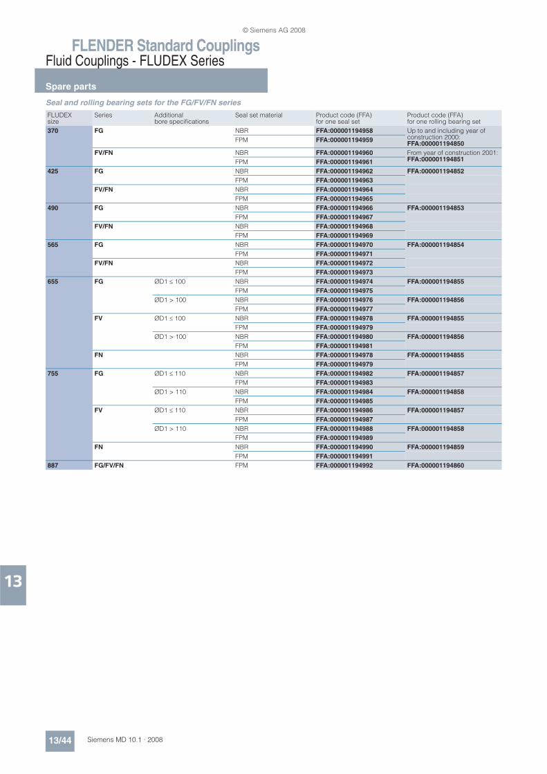
FLENDER Standard CouplingsFluid Couplings - FLUDEX Series
Spare parts
13/44 Siemens MD 10.1 · 2008
13
Seal and rolling bearing sets for the FG/FV/FN series
FLUDEX size
Series Additional bore specifications
Seal set material Product code (FFA) for one seal set
Product code (FFA) for one rolling bearing set
370 FG NBR FFA:000001194958 Up to and including year of construction 2000:FFA:000001194850
FPM FFA:000001194959
FV/FN NBR FFA:000001194960 From year of construction 2001:FFA:000001194851FPM FFA:000001194961
425 FG NBR FFA:000001194962 FFA:000001194852
FPM FFA:000001194963
FV/FN NBR FFA:000001194964
FPM FFA:000001194965
490 FG NBR FFA:000001194966 FFA:000001194853
FPM FFA:000001194967
FV/FN NBR FFA:000001194968
FPM FFA:000001194969
565 FG NBR FFA:000001194970 FFA:000001194854
FPM FFA:000001194971
FV/FN NBR FFA:000001194972
FPM FFA:000001194973
655 FG ØD1 % 100 NBR FFA:000001194974 FFA:000001194855
FPM FFA:000001194975
ØD1 > 100 NBR FFA:000001194976 FFA:000001194856
FPM FFA:000001194977
FV ØD1 % 100 NBR FFA:000001194978 FFA:000001194855
FPM FFA:000001194979
ØD1 > 100 NBR FFA:000001194980 FFA:000001194856
FPM FFA:000001194981
FN NBR FFA:000001194978 FFA:000001194855
FPM FFA:000001194979
755 FG ØD1 % 110 NBR FFA:000001194982 FFA:000001194857
FPM FFA:000001194983
ØD1 > 110 NBR FFA:000001194984 FFA:000001194858
FPM FFA:000001194985
FV ØD1 % 110 NBR FFA:000001194986 FFA:000001194857
FPM FFA:000001194987
ØD1 > 110 NBR FFA:000001194988 FFA:000001194858
FPM FFA:000001194989
FN NBR FFA:000001194990 FFA:000001194859
FPM FFA:000001194991
887 FG/FV/FN FPM FFA:000001194992 FFA:000001194860
© Siemens AG 2008
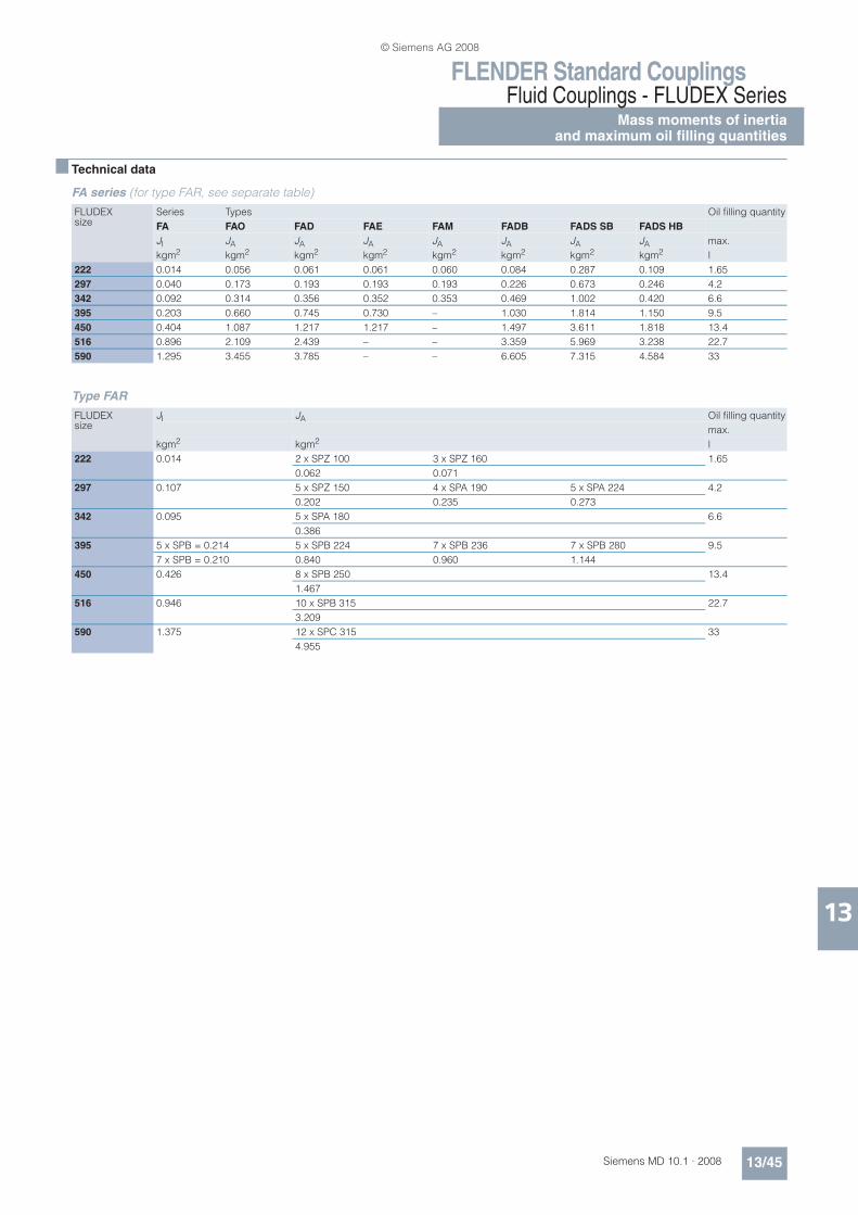
FLENDER Standard CouplingsFluid Couplings - FLUDEX Series
Mass moments of inertiaand maximum oil filling quantities
13/45Siemens MD 10.1 · 2008
13
n Technical data
FA series (for type FAR, see separate table)
Type FAR
FLUDEX size
Series Types Oil filling quantity
FA FAO FAD FAE FAM FADB FADS SB FADS HB
JI JA JA JA JA JA JA JA max.
kgm2 kgm2 kgm2 kgm2 kgm2 kgm2 kgm2 kgm2 l
222 0.014 0.056 0.061 0.061 0.060 0.084 0.287 0.109 1.65
297 0.040 0.173 0.193 0.193 0.193 0.226 0.673 0.246 4.2
342 0.092 0.314 0.356 0.352 0.353 0.469 1.002 0.420 6.6
395 0.203 0.660 0.745 0.730 – 1.030 1.814 1.150 9.5
450 0.404 1.087 1.217 1.217 – 1.497 3.611 1.818 13.4
516 0.896 2.109 2.439 – – 3.359 5.969 3.238 22.7
590 1.295 3.455 3.785 – – 6.605 7.315 4.584 33
FLUDEX size
JI JA Oil filling quantity
max.
kgm2 kgm2 l
222 0.014 2 x SPZ 100 3 x SPZ 160 1.65
0.062 0.071
297 0.107 5 x SPZ 150 4 x SPA 190 5 x SPA 224 4.2
0.202 0.235 0.273
342 0.095 5 x SPA 180 6.6
0.386
395 5 x SPB = 0.214 5 x SPB 224 7 x SPB 236 7 x SPB 280 9.5
7 x SPB = 0.210 0.840 0.960 1.144
450 0.426 8 x SPB 250 13.4
1.467
516 0.946 10 x SPB 315 22.7
3.209
590 1.375 12 x SPC 315 33
4.955
© Siemens AG 2008

FLENDER Standard CouplingsFluid Couplings - FLUDEX SeriesMass moments of inertiaand maximum oil filling quantities
13/46 Siemens MD 10.1 · 2008
13
FG/FV series
FN series (for type FNDB, see separate table)
FLUDEX size
Series Types Oil filling quantity
FG FV FGO FVO FGD FVD FGE FVE FGM FVM FG FV
JI JI JA JA JA JA JA JA JA JA max. max.
kgm2 kgm2 kgm2 kgm2 kgm2 kgm2 kgm2 kgm2 kgm2 kgm2 l l
370 0.191 0.191 0.519 0.551 0.571 0.603 0.571 0.603 0.571 0.603 7.2 8
425 0.342 0.342 0.819 0.876 0.989 1.046 0.974 1.031 0.963 1.020 11 12
490 0.723 0.723 1.992 2.110 2.312 2.430 2.272 2.390 2.264 2.382 17 18.5
565 1.269 1.269 3.216 3.441 3.696 3.921 3.636 3.861 3.616 3.841 25.5 28
655 2.567 2.567 7.287 7.757 8.687 9.157 – – – – 40 44
755 4.856 4.856 12.575 13.291 14.775 15.491 – – – – 61 67
887 11.817 11.817 26.832 28.212 30.102 31.482 – – – – 98 107
FLUDEX size
Hub carrier Series Types Weights Oil filling quantity
FN FNO FNA FND FNDS SB FNDS HB
JA JI JI JI JI JI Y FY max.
Hub kgm2 kgm2 kgm2 kgm2 kgm2 kgm2 mm N l
370 Standard 0.657 0.237 0.281 0.320 1.180 0.386 197 665 8.2
Long 0.647 227
425 Standard 1.107 0.343 0.470 0.491 1.841 0.659 224 940 12.5
Long 1.102 254
490 Standard 2.480 0.737 0.954 0.999 3.009 1.285 235 1420 19
Long 2.474 265
565 Standard 4.175 1.364 1.715 1.835 5.075 2.081 278 1900 29
Long 4.251 318
655 Standard 9.319 2.567 3.587 3.777 6.777 4.701 330 3000 45
Long 9.523 370
755 Standard 15.616 4.910 6.878 7.198 12.078 9.689 352 4200 69
Long 15.950 392
887 Standard 33.662 11.832 15.132 16.632 24.030 20.428 406 6900 110
Long 34.462 456
© Siemens AG 2008

FLENDER Standard CouplingsFluid Couplings - FLUDEX Series
Mass moments of inertiaand maximum oil filling quantities
13/47Siemens MD 10.1 · 2008
13
Type FNDB
JI Mass moment of inertia of the inner rotor (hollow shaft (106)/shaft (106) + blade wheel (105) + any parts of the add-on coupling connected to them) in kgm2
JA Mass moment of inertia of the outer housing (shell (101) + cover (102) + any hub carrier (120) or add-on coupling) in kgm2
Mass moments of inertia J (including the power-transmitting oil filling components) apply to maximum bores
Y Centroidal distance of the drive-side coupling masses, measured from the hub end face of the hub carrier.
FY Effective weight in mass center
FLUDEX size
Hub carrier Brake drum JA JI Weights Oil filling quantity
Y FY max.
Hub ØDBT x BBT kgm2 kgm2 mm N l
370 Standard Ø315 x 118 0.657 0.640 197 665 8.2
Ø400 x 150 1.341
Long Ø315 x 118 0.647 0.640 227
Ø400 x 150 1.341
425 Standard Ø315 x 118 1.107 0.811 224 940 12.5
Ø400 x 150 1.492
Long Ø315 x 118 1.102 0.811 254
Ø400 x 150 1.492
490 Standard Ø400 x 150 2.480 1.994 235 1420 19
Ø500 x 190 4.009
Long Ø400 x 150 2.474 1.994 265
Ø500 x 190 4.009
565 Standard Ø400 x 150 4.175 2.835 278 1900 29
Ø500 x 190 4.775
Long Ø400 x 150 4.251 2.835 318
Ø500 x 190 4.775
655 Standard Ø500 x 190 9.319 6.677 330 3000 45
Ø630 x 236 11.577
Long Ø500 x 190 9.523 6.677 370
Ø630 x 236 11.577
755 Standard Ø630 x 236 15.616 15.178 352 4200 69
Long 15.950
887 Standard Ø710 x 265 33.662 30.832 406 6900 110
Long 34.462
© Siemens AG 2008

FLENDER Standard CouplingsFluid Couplings - FLUDEX Series
Special types
13/48 Siemens MD 10.1 · 2008
13
n Selection and ordering data
Selection of additional ordering data
Special types Additional ordering data -Z with order code and, if necessary with plain text specification
Oil filling
Without oil filling and without oil filling quantity specification stamped on the coupling Without addition – standard
With oil filling (specification of oil filling quantity “+Y90” required) F16
With specification of oil filling quantity Y90 • and orderer specification
Thermal equipment
Standard type (fuse 140 °C, seal set Perbunan) Without addition – standard
Fuse 110 °C, seal set Perbunan F01
Explosion protection in conformity to 94/9EG ATEX100A, seal set Perbunan F02
Thermal switch 110 °C, fuse 140 °C, seal set Perbunan (option not available with size 222) F03
EOC transmitter 125 °C, fuse 160 °C, seal set Perbunan (option not available with size 222) F04
Explosion protection in conformity to 94/9EG ATEX100A, seal set Viton F06
Fuse 110 °C, seal set Viton F05
Fuse 140 °C, seal set Viton F07
Fuse 160 °C, seal set Viton F08
Thermal switch 110 °C, fuse 140 °C, seal set Viton (option not available with size 222) F10
Thermal switch 140 °C, fuse 160 °C, seal set Viton (option not available with size 222) F11
EOC transmitter 125 °C, fuse 160 °C, seal set Viton (option not available with size 222) F12
For preservation, see catalog section 3
Drive
Standard drive side Without addition – standard
FA series with housing drive F23
FG/FV/FN series with impeller drive F24
Position
Horizontal version Without addition – standard
Vertical version, motor overhead (option not permitted in FV and FN series) F13
Vertical version, motor underneath F14
© Siemens AG 2008

FLENDER Standard CouplingsFluid Couplings - FLUDEX Series
Special types
13/49Siemens MD 10.1 · 2008
13
• This order code designates only the type price – plain text required additionally.
Shaft and bore
Shaft insertion depth to DIN 748/1 Without addition – standard
Shaft insertion depth 1 deviating from DIN 748/1 Y28 and plain text specification for L1
Shaft insertion depth 2 deviating from DIN 748/1 Y29 and plain text specification for L2
Bore tolerance ISO H7 Without addition – standard1)
Bore tolerance ISO K7 for hollow shafts with imperial bores L13/M131)
Bore tolerance ISO M7 for hub parts with imperial bores L14/M141)
Keyway to DIN 6885/1 or DIN 6885/3 keyway width JS9 Without addition – standard
Keyway to ASME B17.1, if necessary with reduced keyway depth L43/M431)
2 parallel keyways set 180° apart L46/M461)
Half parallel key balancing (before keyseating) Without addition – standard
Full parallel key balancing (after keyseating) L52/M521)
Internal add-on parts
No additional internal add-on parts Without addition – standard
With baffle plate (only for FA series) F17
With damming ring F18
With damming delay chamber (only for FV and FN series) F19
For documentation, test certificates and acceptances, see catalog section 3 2)
No test certificate, acceptance certificates Without addition – standard
Other additions
Micro-balancing, high speed W03
With special fixed bearings F20
With additional dust seal F21
Special data Y99 and plain text specification
Special types Additional ordering data -Z with order code and, if necessary with plain text specification
1) Order code “L..” for hollow shaft side and “M..” for opposite side. 2) Surface crack and ultrasound testing are not possible on FLUDEX couplings.
© Siemens AG 2008
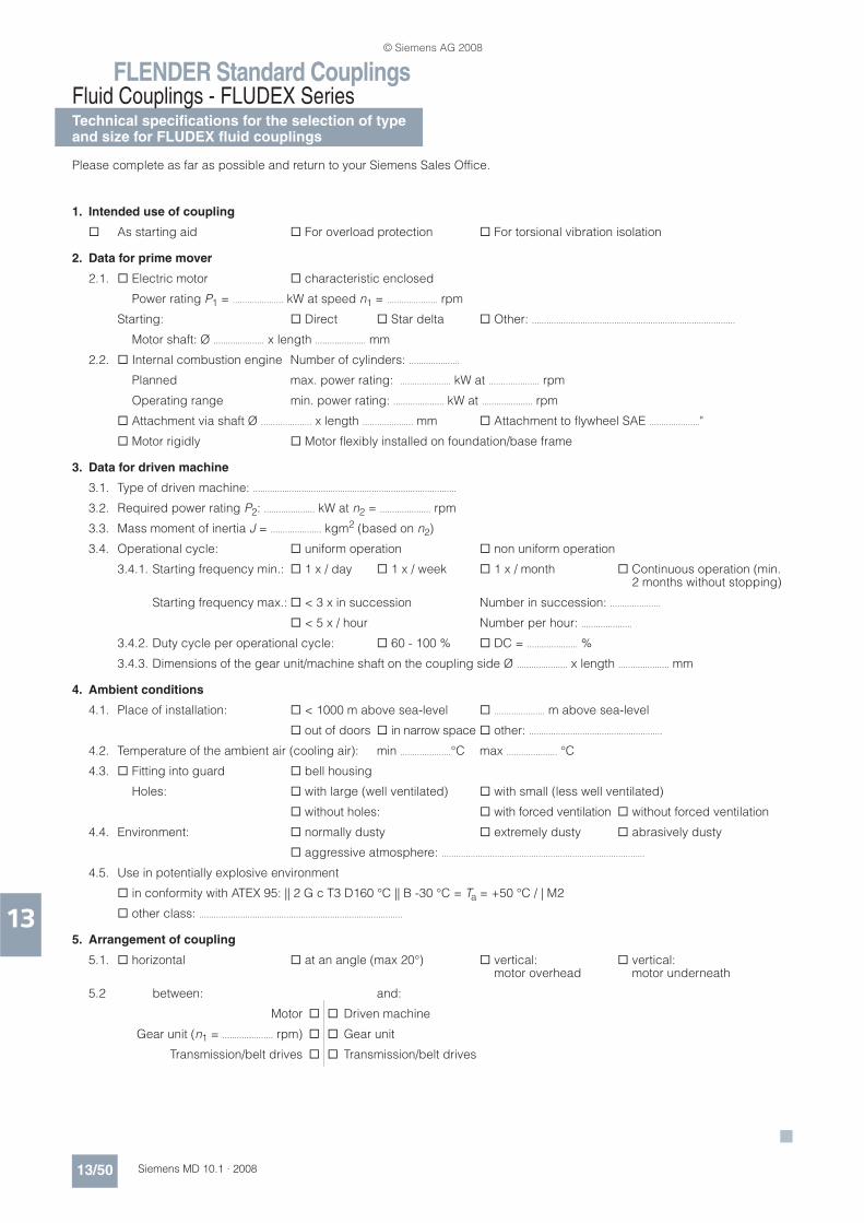
FLENDER Standard CouplingsFluid Couplings - FLUDEX SeriesTechnical specifications for the selection of typeand size for FLUDEX fluid couplings
13/50 Siemens MD 10.1 · 2008
13
Please complete as far as possible and return to your Siemens Sales Office.
1. Intended use of coupling
As starting aid For overload protection For torsional vibration isolation
2. Data for prime mover
2.1. Electric motor characteristic enclosed
Power rating P1 = ..................... kW at speed n1 = ..................... rpm
Starting: Direct Star delta Other: ....................................................................................
Motor shaft: Ø ..................... x length ..................... mm
2.2. Internal combustion engine Number of cylinders: .....................
Planned max. power rating: ..................... kW at ..................... rpm
Operating range min. power rating: ..................... kW at ..................... rpm
Attachment via shaft Ø ..................... x length ..................... mm Attachment to flywheel SAE ....................."
Motor rigidly Motor flexibly installed on foundation/base frame
3. Data for driven machine
3.1. Type of driven machine: ....................................................................................
3.2. Required power rating P2: ..................... kW at n2 = ..................... rpm
3.3. Mass moment of inertia J = ..................... kgm2 (based on n2)
3.4. Operational cycle: uniform operation non uniform operation
3.4.1. Starting frequency min.: 1 x / day 1 x / week 1 x / month Continuous operation (min. 2 months without stopping)
Starting frequency max.: < 3 x in succession Number in succession: .....................
< 5 x / hour Number per hour: .....................
3.4.2. Duty cycle per operational cycle: 60 - 100 % DC = ..................... %
3.4.3. Dimensions of the gear unit/machine shaft on the coupling side Ø ..................... x length ..................... mm
4. Ambient conditions
4.1. Place of installation: < 1000 m above sea-level ..................... m above sea-level
out of doors in narrow space other: .......................................................
4.2. Temperature of the ambient air (cooling air): min .....................°C max ..................... °C
4.3. Fitting into guard bell housing
Holes: with large (well ventilated) with small (less well ventilated)
without holes: with forced ventilation without forced ventilation
4.4. Environment: normally dusty extremely dusty abrasively dusty
aggressive atmosphere: ....................................................................................
4.5. Use in potentially explosive environment
in conformity with ATEX 95: || 2 G c T3 D160 °C || B -30 °C = Ta = +50 °C / | M2
other class: ....................................................................................
5. Arrangement of coupling
5.1. horizontal at an angle (max 20°) vertical: vertical:motor overhead motor underneath
5.2 between: and:
Motor Driven machine
Gear unit (n1 = ..................... rpm) Gear unit
Transmission/belt drives Transmission/belt drives
© Siemens AG 2008