Flues and chimney systems
60
Flues and chimney systems 191 Chapter 7
Transcript of Flues and chimney systems

Flues and chimney systems
191
Chapter 7

regulations and standards on flues and chimney systems
classification of chimneys and appliances
working principles and features of open-flued systems
types of open flues
working principles of room-sealed systems
types of room-sealed flues
testing gas appliance flue systems
analysing flue combustion products before commissioning
This uniT covers
Flue A flue is a passage for conveying the products of combustion to the outside atmosphere.
chimney A chimney is a structure consisting of a wall or walls enclosing a flue or flues.
Key terms
192
NVQ Diploma Level 3 Gas
IntroductIonIn this chapter you will be instructed on the standards of chimneys and flue systems that can be used with gas appliances. Flues and chimney systems are an integral part of an appliance’s installation. It is important that you, as a gas operative, understand the need for them in the effective removal of the products of combustion, how they are constructed and the materials that they can be manufactured from.
regulaTions and sTandards on Flues and chimney sysTems
As with all aspects of gas installation work, there are certain standards and regulations which must be adhered to. With respect to working on flues and chimney systems, there are rules laid out in British Standards (BS) and in the Gas Safety (Installation and Use) Regulations (GSIUR). There are rules set out for the designer, supplier and installer of flue and chimney systems and for landlords with regard to their maintenance.
The standard relevant to this area of work is BS 5400 Flueing and ventilation for gas appliances of rated input not exceeding 70 kW net (1st, 2nd and 3rd family gases) – Part 1 Specification for installation of gas appliances to chimneys and for maintenance of chimney and Part 2 Installation and maintenance of flues and ventilation for gas appliances. As with other work on gas, it is essential that persons carrying out work on the flues for gas appliances are competent to do so, and any work that is subject to the GSIUR must comply with these requirements.
The building regulation which applies to gas appliances is Approved Document J (Combustion Appliances and Fuel Storage Systems). This document has been updated and came into force on the 1 October 2010. Section 1 sets out the general provisions which apply to combustion installations. For the safe accommodation of combustion appliances, you must ensure:
there is sufficient air for combustion purposes and where necessary for the cooling of the appliance
that appliances operate normally without the products of combustion (POC) causing a hazard to health (spillage)
that a device is fitted to warn of carbon monoxide where a fixed appliance is installed
that the appliance operates without causing damage to the fabric of the building through heat exposure
that the appliance and chimney/flue have been inspected and are fit for the purpose intended
that the chimney/flue has been labelled to indicate its performance capabilities.

193
Chapter 7: FLUES AND CHIMNEY SYSTEMS
Exchange of information and planningThe designer or installer of the chimney, and the provider or installer of the gas appliance should agree and document the important compatibility details with the customer as appropriate. When erecting a new chimney or chimney configuration or modifying an existing one, these important details include:
the type, size and route of the chimney the type and size/heat input of the gas appliance that is intended to be
connected to it.
This is particularly important when different trades are involved in the erection of the chimney or chimney configuration and the fitting of the gas appliance.
When you are fitting a gas appliance to an existing open-flue chimney or room-sealed chimney configuration, it is essential that you confirm that the chimney is suitable for the appliance. When the chimney is provided as part of the appliance, for example a room-sealed configuration (including balanced flue), you should agree and document, with the customer, that the chimney configuration is suitable for the application. When you are installing either a new or replacement appliance to an existing chimney/flue configuration you are responsible for checking that the installation is suitable for the appliance being installed.
Maintenance of fluesThe responsible person (e.g. landlord) should be advised that, for continued efficient and safe operation of the appliance and its chimney, it is important that adequate and regular maintenance is carried out by a competent person (i.e. a Gas Safe registered gas installer) in accordance with the appliance manufacturer’s recommendations.
The GSIUR impose a general obligation on landlords who provide appliances in tenanted premises to have them maintained and checked for safety every 12 months.
classiFicaTion oF chimneys and appliances
Under the Accredited Certification Scheme (ACS) convention you will be required to identify types of appliances and category of the flue system. It is important that you, as a gas operative, are able to undertake this task. It is your responsibility to know if the appliance is correct for a given situation. This section informs you of the classification types.
Classification of chimneysChimneys are classified according to BS EN 1443:2003, according to the following performance characteristics:
temperature class pressure class

194
NVQ Diploma Level 3 Gas
resistance to condensate class corrosion resistance class soot-fire resistance class (G or O), followed by a distance to
combustibles.
Chimney products are specified in the European chimney standards according to the materials which are being used, i.e. concrete, clay/ceramic, metal or plastic.
Classification of appliancesAll appliances are now classified by PD CR 1749:2005; this is the new European standard for the method of evacuation of the POC. It means that the classification of appliances burning combustible gases is the same across the European Community.
There are three main types of appliance, grouped according to how they discharge their POC:
Type a Flueless – This type of appliance is not intended for connection to a flue or any device for evacuating the POC to the outside of the room in which the appliance is installed. Products of combustion are released into the room in which the appliance is installed. The air for combustion is taken from the room.
Type B open-flued – This type of appliance is intended to be connected to a flue that evacuates the POC to the outside of the room containing the appliance. The air for combustion is taken from the room.
Type c room-sealed – The air supply, combustion chamber, heat exchanger and evacuation of POC (i.e. the combustion circuit) for this type of appliance is sealed with respect to the room in which the appliance is installed.
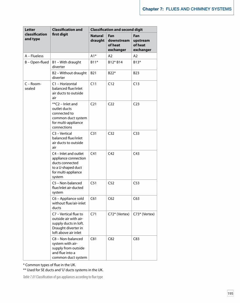
These types of appliance are then further classified according to flue type, as shown in Table 7.01 opposite.
1 Which of the Building Regulations would you refer to for combustion appliances?
2 Complete the following description: ‘Type A Flueless appliances are. . .’
3 Type C appliances are classified as which type of appliance?
a Flueless b Open-flued c Room-sealed d All of the above
4 Which type of appliance would you install in SE duct or ‘U’ duct systems in the UK?
5 Complete the following requirements: ‘When erecting a new chimney or chimney configuration or modifying an existing one, the important details shall include . . .’
progress check
195
Chapter 7: FLUES AND CHIMNEY SYSTEMS
letter classification and type
classification and first digit
classification and second digit
natural draught
Fan downstream of heat exchanger
Fan upstream of heat exchanger
A – Flueless A1* A2 A2
B – Open-flued B1 – With draught diverter
B11* B12* B14 B13*
B2 – Without draught diverter
B21 B22* B23
C – Room-sealed
C1 – Horizontal balanced flue/inlet air ducts to outside air
C11 C12 C13
**C2 – Inlet and outlet ducts connected to common duct system for multi-appliance connections
C21 C22 C23
C3 – Vertical balanced flue/inlet air ducts to outside air
C31 C32 C33
C4 – Inlet and outlet appliance connection ducts connected to a U-shaped duct for multi-appliance system
C41 C42 C43
C5 – Non-balanced flue/inlet air-ducted system
C51 C52 C53
C6 – Appliance sold without flue/air-inlet ducts
C61 C62 C63
C7 – Vertical flue to outside air with air-supply ducts in loft. Draught diverter in loft above air inlet
C71 C72* (Vertex) C73* (Vertex)
C8 – Non-balanced system with air-supply from outside and flue into a common duct system
C81 C82 C83
* Common types of flue in the UK.** Used for SE ducts and ‘U’ ducts systems in the UK.
Table 7.01 Classification of gas appliances according to flue type

Type B11
Type B14 Type B22 Type B23
Type B12
Type A1
Type B13
Open-�ued types
Flueless
Figure 7.01 Typical appliances of types A and B
196
NVQ Diploma Level 3 Gas

197
Chapter 7: FLUES AND CHIMNEY SYSTEMS
Multi-storey Multi-storey
Type C21 SE-Duct system
Type C41 U-Duct system
Type C11
Type C13
Type C12
Figure 7.02 Room-sealed type C appliances
Vertex �ue
Type C73Type C33Type C32
Room-sealedvertical discharge
Figure 7.03 Room-sealed type C vertical terminations
198
NVQ Diploma Level 3 Gas
WorKing principles and FeaTures oF open-Flued sysTems
Open flues are still an integral part of appliance installation, in particular when fitting space heating appliances (gas fires). You need to understand the importance of ensuring that the flue is correct for the installation.
Type B Open-flued (natural draught)Natural draught systems take combustion air from the room and the POC travel up the flue by natural draught or ‘flue pull’. This is caused by the difference in the densities of hot flue gases and the cold air outside.
The strength of the flue pull or draught is increased when the flue gases are hotter or if the flue height is increased. Factors that will slow down the flue pull are 90 o bends and horizontal flue runs, so these must be avoided.
This flue draught is created by natural means and is quite slight, so it is important to design/install a flue carefully to allow for the necessary up-draught. Fans can be fitted in flues to overcome problems and allow more flexibility. See the section on ‘Type B Open-flued forced (fanned draught)’ on page 201.
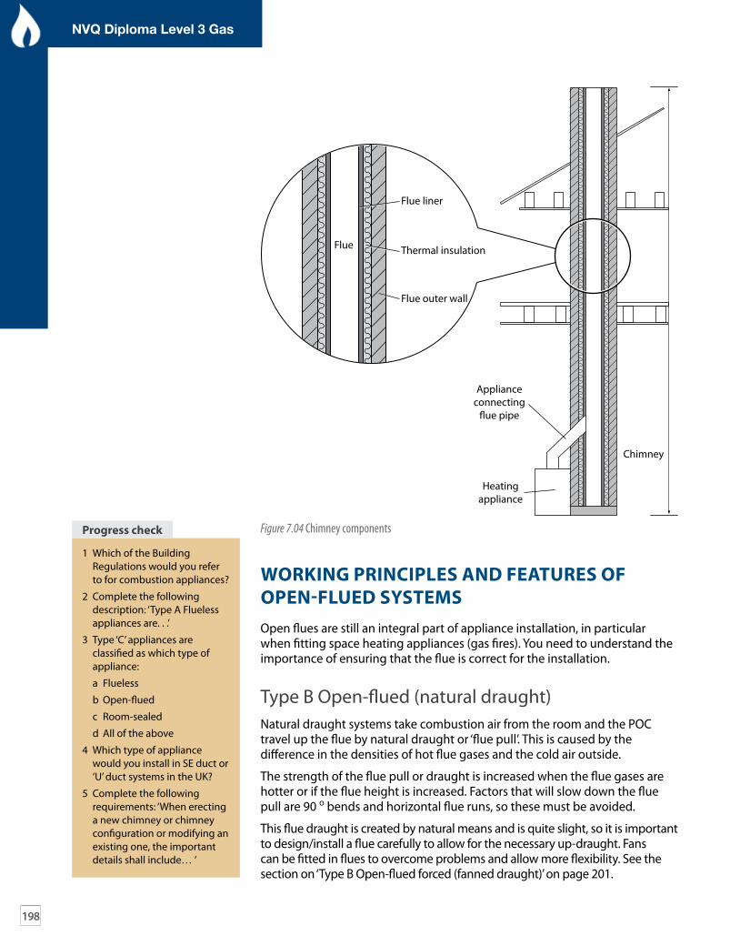
Flue
Flue liner
Flue outer wall
Chimney
Heatingappliance
Applianceconnecting
�ue pipe
Thermal insulation
Figure 7.04 Chimney components
1 Which of the Building Regulations would you refer to for combustion appliances?
2 Complete the following description: ‘Type A Flueless appliances are. . .’
3 Type ‘C’ appliances are classified as which type of appliance:
a Flueless
b Open-flued
c Room-sealed
d All of the above
4 Which type of appliance would you install in SE duct or ‘U’ duct systems in the UK?
5 Complete the following requirements: ‘When erecting a new chimney or chimney configuration or modifying an existing one, the important details shall include… ’
progress check
199
Chapter 7: FLUES AND CHIMNEY SYSTEMS
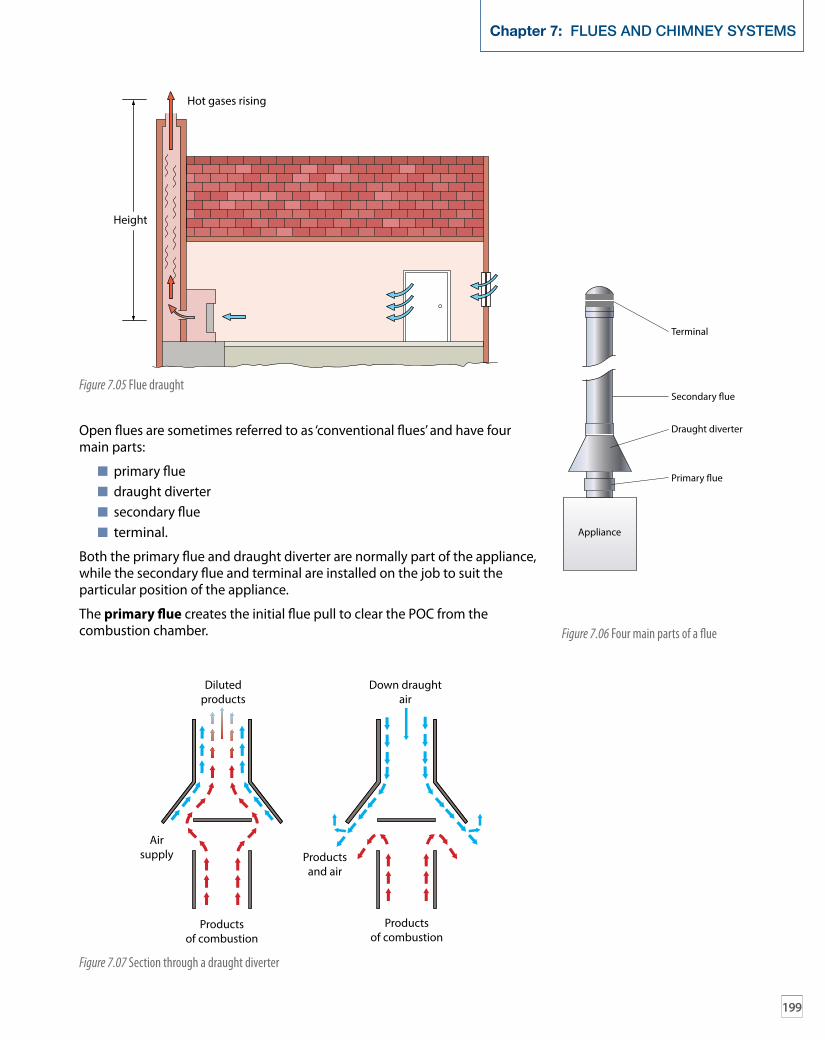
Open flues are sometimes referred to as ‘conventional flues’ and have four main parts:
primary flue draught diverter secondary flue terminal.
Both the primary flue and draught diverter are normally part of the appliance, while the secondary flue and terminal are installed on the job to suit the particular position of the appliance.
The primary flue creates the initial flue pull to clear the POC from the combustion chamber.
Hot gases rising
Height
Figure 7.05 Flue draught
Appliance
Primary �ue
Draught diverter
Terminal
Secondary �ue
Figure 7.06 Four main parts of a flue
Airsupply
Productsof combustion
Productsof combustion
Dilutedproducts
Down draughtair
Productsand air
Figure 7.07 Section through a draught diverter

200
NVQ Diploma Level 3 Gas
The draught diverter:
diverts any downdraught from the secondary flue from the combustion chamber of the appliance, as this can interfere with the combustion process
allows dilution of flue products with air breaks any excessive pull on the flue (i.e. in windy weather), as this can
also interfere with the combustion process.
Where a draught diverter is fitted it should be installed in the same space as the appliance.The secondary flue passes all the POC up to the terminal and should be constructed in such a way as to give the best possible conditions for the flue to work efficiently. Resistance of the installed components should be kept to a minimum by:
avoiding horizontal/shallow runs keeping bends to a minimum of 45 ° keeping flues internal where possible (warm) providing a 600 mm vertical rise from the appliance to the first bend fitting the correctly sized flue – at least equal size to the appliance
outlet and as identified by the manufacturer.
The terminal is fitted on top of the secondary flue. Its purpose is to:
help the flue gases discharge from the flue prevent rain, birds and leaves etc. from entering the flue minimise downdraught.
You should fit terminals to flues with a cross-sectional area of 170 mm or less. The terminal needs to be suitable for the appliance type fitted to the flue.
Terracotta chimney rain inserts are not suitable for use with gas appliances. Only use approved terminals, as these have been checked for satisfactory
Figure 7.08 Acceptable terminals

201
Chapter 7: FLUES AND CHIMNEY SYSTEMS
performance and have limited openings of not less than 6 mm but not more than 16 mm (except for incinerators, which are allowed 25 mm). Figures 7.08 and 7.09 show examples of acceptable and unacceptable types of terminals for use with certain flue systems.
Type B Open-flued forced (fanned draught)Fanned draught flues allow for greater flexibility in the positioning of the appliance. There are two types of fanned draught flue systems:
where the fan is an integral part of the appliance (positive pressure) where a fan is located in the outlet to a chimney or flue system
(negative pressure) and has been specified or supplied by the appliance manufacturer.
Where the fan is not factory fitted, always connect it to the appliance in accordance with the appliance manufacturer’s instructions. Do not make any modifications to the appliance without the agreement of the appliance manufacturer.
When fitting a fan in the chimney/flue system, ensure the fan size allows for full clearance of POC against adverse wind pressures. This also includes the route which the chimney/flue must take and requires you to calculate the resistance to flow (including the specified adverse pressure) at the design flow rate and to compare it with the pressure available from the chosen fan. The responsibility for safe installation lies with the installer and the appliance manufacturer.
Proprietary fan kits are available from manufacturers and include fail safe features to prevent the appliance from operating should the fan fail.
Figure 7.09 Unacceptable flue terminals
minimum flow rates for fanned flues
appliances maximum co2 concentration (%)
minimum flue flow rate (m3/h per kW input*)
Gas fire 1 10.7
Fire/back boiler 2 5.4
All other appliances 4 2.6
* These figures refer to natural gas.
Table 7.02 Minimum flow rates for fanned flues
Table 7.02 may be used to calculate flue velocity although care is required to relate a specific measured velocity to a mean volumetric flue flow rate. The

202
NVQ Diploma Level 3 Gas
final test for correct operation of a chimney is a spillage test at the appliance. For decorative fuel effect gas appliances you should refer to BS 5871-3.
Safety controlWhere fans are fitted in secondary chimneys/flues they should incorporate a safety control in the secondary flue which is external to the appliance. The safety device should be capable of cutting off the flow of gas to the main burner if the flow in the secondary flue becomes insufficient for more than 6 secs.
The safety control means the flue flow sensor must be in the ‘no flow’ position before the fan can be set in operation. Should the safety control be activated then manual intervention is required to re-establish the gas supply to the main burner, unless the appliance incorporates a flame supervision device (FSD) and the correct flue flow is re-established.
Types oF open Flues and chimneys
There are certain considerations that must be taken into account when fitting new chimneys and open flues, including the construction materials of the flue/chimney and their suitability for the particular appliance and circumstances.
Always read the manufacturer’s instructions to check if the appliance is suitable for the flue it is being installed with.
Chimney construction materialsWhere new open-flued appliances are fitted, the chimney should be designed to comply with BS EN 15287-1 Chimneys – Design, installation and commissioning of chimneys (Part 1: Chimneys for non-room-sealed heating appliances). These chimneys are classified as being allowed by the manufacturer. New chimneys can be classed as system chimneys or custom-built chimneys.
Chimney/flue construction materials must now be capable of removing condensed combustion products which are mildly acidic. Materials such as copper, mild steel and lower grades of stainless steel are not suitable for this type of application.
Where a new chimney is being installed, the chimney should be constructed from either brick (or other masonry) or flue blocks. Brick/masonry chimneys should be lined with clay liners conforming to BS EN 1457 or concrete liners conforming to BS EN 1857. Poured concrete linings are not acceptable as a method of lining new masonry chimneys. Flue block chimneys should be lined with clay conforming to BS EN 1806 or concrete conforming to BS EN 1858.
Rigid fluesWhere factory-made insulated metal chimneys are used, they must conform to BS EN 1856-1. If they are single walled then they must not be used externally. When chimneys are used externally, they must be twin walled to BS EN 1856-1 and installed to manufacturers’ instructions.

203
Chapter 7: FLUES AND CHIMNEY SYSTEMS
Rigid metallic flues
Twin-wall metal fluesTwin-walled metal flues are available in a variety of lengths and diameters, with a vast range of fittings and brackets to suit every installation. You should consult the manufacturers’ information booklets to familiarise yourself with the range of products available before deciding which to fit.
Non-combustiblematerial acting as�re-stop
Light sheet metal
25 mm min.
Metal ceiling plate
Plasterboard
Timber �ooring
Metal �oor plate
Flue pipe
Figure 7.10 Flue passing through combustible material
There are two types of twin-walled flues: fully insulated or with an air gap. Twin-walled flues with an air gap are only suitable for use internally but can be used externally for lengths less than 3 m. For all other external situations fully insulated twin-walled pipe should be used.
The joints are designed to be fitted with the ‘male’ or spigot end uppermost. Where a pipe passes through a combustible material like a floor/ceiling, a sleeve must be provided to give a minimum circular space of 25 mm (see Figure 7.10).
Where a flue pipe passes through a tiled sloping roof (see Figure 7.11 on page 204), a purpose-made weathering slate is required with an upstand of 150 mm minimum at the rear of the slate. Aluminium weathering slates are also available to purchase. You should always consult the manufacturer’s instructions before fitting the weathering slate.
Vitreous-enamelled steel fluesA vitreous-enamelled steel flue is a single-skin pipe available in many lengths and sizes, although it can be cut to any length. It is often used as the connection between an appliance and the main flue, and may include a disconnecting collar to allow appliance removal. The socket on single-wall pipe is fitted uppermost, unlike the twin-wall.

204
NVQ Diploma Level 3 Gas
Asbestos fluesUnder no circumstances should asbestos cement materials be used for new flue pipes. Where an existing chimney is suspected to be made of asbestos cement or contain asbestos then a risk assessment must be conducted prior to carrying out any work. See the section on ‘Risk assessments’ (page 62).
You should only reuse an existing asbestos cement chimney or chimney component if it is sound and does not require cutting or machining. More information regarding asbestos-related products can be found on the HSE website.
Pre-cast concrete flue blocksPre-cast concrete flue blocks are the same size and shape as a house brick and can therefore be built into (or ‘bonded’ with) the walls of a new property during construction. Non-bonded blocks are available and are more suited to existing properties.
You must use flue blocks certified to BS EN 1858 and fit them to the manufacturer’s instructions. Excess cement should be carefully removed from the block during construction and no air gaps should be left.
All flue blocks must be laid spigot end up with a 3mm thick complete and gas-tight joint. The most convenient method of jointing is to apply cartridges of ready-mixed high-temperature mortar with a cartridge gun. Always use the nozzle and cut it 35 mm from the end to give an 8 mm bead. Before jointing, ensure the upper face of the block is dry and clear of debris.
Particular attention should be given to the connection from the flue blocks to the ridge terminal; the flue pipe installed should be of twin-wall insulated
150 mm upstand
Insulating sleeve
Weatheringslate
Weatheringcollar
Figure 7.11 Flue passing through sloping roof

205
Chapter 7: FLUES AND CHIMNEY SYSTEMS
pipe construction using the correct fittings. When a metal chimney is connected to a flue block system then a transfer block must be used. When making the connection, be sure not to let the metal flue component project into the flue as this would cause a restriction of the cross-sectional area of the flue system.
Flue block chimneys should not be directly faced with plaster, as the heat will cause the plaster to crack. They should be faced with either concrete (or similar material) blocks or with plasterboard. Where plasterboard is used as dry lining, the dabs or batons should not be in direct contact with the flue blocks. You must also ensure that no fixing devices penetrate the blocks and that the joint between the facing and the blocks is sealed around the fireplace opening. An example is where plasterboard has been fitted and the gap between the blocks and the plasterboard must be sealed to prevent POC from escaping between the gap.
Where a new chimney is constructed using flue blocks, the minimum cross-sectional area should not be less than 16,500 mm2 with no dimension less
T
T
W
L B
L = �ue breadthW = �ue widthT = wall thicknessB = bonding extension
W
Starter block
Lateral o�set block
Rear o�set block
Transfer block (di�erent projections)
Plain block Cover block
Figure 7.12 Flue blocks

206
NVQ Diploma Level 3 Gas
than 90 mm. There are, however, appliances which cannot be connected to flue blocks which have a cross-sectional area between 12,000 mm2 and 13,000 mm2 or a minor dimension of 63 mm or less. These are:
drying cabinets appliances having a flue duct outlet area greater than 13,000 mm2
gas fires and combined appliances incorporating a gas fire, unless a special starter block/adapter has been designed for the purpose, tested and supplied by the appliance manufacturer or the appliance manufacturer’s instructions specifically state that this is acceptable.
Some manufacturers state that their appliances are not suitable for connection to flue block systems of certain sizes constructed to BS 1289:1975. Further guidance is given in BS 5440 – Part 1:2008.
Figure 7.13 below shows a detail of a completed installation with flue blocks.
Pre-case flue blocks can have a bad reputation for poor flue performance and spillage of the POC. This is because they have been badly installed in the past. As with any open flue, always ensure that a thorough visual inspection of the flue system is conducted. You should be particularly careful when measuring the cross-sectional area to ensure accuracy, and always conduct adequate spillage tests prior to handover.
Roof space
3
4
3333333333333
33333
555
2111
First �oor
Secondary �ue, must be twin walled
1 = starter block2 = lintel cover block3 = plain bonding block4 = o�set transfer block5 = lateral o�set block
May be produced asone- or two-piece set
Figure 7.13 Complete flue-block installation

207
Chapter 7: FLUES AND CHIMNEY SYSTEMS
Other types of open flue
Flexible stainless steel flues – linersFlexible stainless steel flues must comply with BS EN 1856-2. They are used internally to line existing flues that do not have a suitable clay lining as part of the original building construction. Liners are also used when the existing chimney or flue has given unsatisfactory performance in the past.
Liners must be installed in one continuous length and not be joined to reach the required length. Any bends in the liner must be of a maximum of 45 o and there should be no kinks or tears present.
It is essential to secure liners with a clamp plate and to seal the top and the base of the chimney. A sealing plate must be included at the base of the flue system to prevent debris from falling into the appliance opening and onto the appliance. Where the diameter of the flue is less than 170 mm, use an approved terminal to protect the end of the liner.
Figure 7.14 Terminal ridge tile
1.5 m minimum300 mm minimum
Figure 7.15 Positioning of ridge vents

208
NVQ Diploma Level 3 Gas
The liner should not project more than a nominal 25 mm below the plate. Where gas supplies are to be made through the wall of a gas flue box (4 and 5, Figure 7.16) it should be routed as close as practicable to the bottom of the box and sealed with non-setting sealant.
Where flexible liners are connected to the tops of flue boxes they should rise as near vertical as possible no angle should be any greater than 45 o. The correct method of connecting flexible flues to a gas fire back boiler is shown in Figure 7.17 – note the disconnection socket and the sealing plate.A typical way of sealing the annular space between the chimney and the flexible flue liner would be with mineral wool. For larger openings, it might be necessary to use, for example, a register plate to hold the mineral wool in place. Follow the advice given by the liner manufacturer, particularly in relation to the location of the liner where it passes around bends in the chimney.
1
2
3
4 5 6 7
Key1 Flue liner conforming to BS EN 1856-22 Joints to be well made where the closure plate or the flue box is sealed to the face of the opening or
fire surround3 Debris or register plate4 Flue liner connected to a proprietary flue gas collector. For use with an appliance with a closure plate5 Flue liner conforming to BS EN 1856-2 connected to a gas flue box conforming to BS 7156 Flue liner secured and sealed into a proprietary gather above the builder’s opening7 Flue liner mechanically secured and sealed with a clamp to a debris or register plate above a
builder’s opening
Figure 7.16 Connections for flexible stainless steel liner

209
Chapter 7: FLUES AND CHIMNEY SYSTEMS
Unless otherwise stated by the manufacturer, decorative fuel effect fires must be installed with a minimum flue size of 175 mm diameter.
When chimneys exceed certain lengths, they may need to be lined, depending on the type of appliance fitted, as shown in Table 7.03.
appliance type Flue length
Gas fire > 10 m (external wall)
> 12 m (internal wall)
Gas fire with back boiler Any length
Gas fire with circulator > 10 m (external wall)
> 12 m (internal wall)
Circulator > 6 m (external wall)
> 1.5 m (external length and total length > 9m)
Other appliance Flue lengths greater than in Table 7.05 (see page 213)
Table 7.03 Required flue lining for different appliances
Boiler controls
Access to controls andpassage for combustion air
Fire guard
Sealed to wall
Gas �re
Louvres
Fire �ueconnection
Flue liner
Flue sealing plate
Flue connectionsocket
Boiler �ue hood
Boiler heatexchanger
Burner
Figure 7.17 Sealing plate at base of flue liner

210
NVQ Diploma Level 3 Gas
Shared fluesIn special cases you are allowed to connect two or more appliances into the same flue, but special rules apply. BS 5440 Part 1:2008 identifies six important rules:
Each appliance shall have a draught diverter. Each appliance shall have a flame-supervision device. Each appliance shall have a safety control (an atmospheric sensing
device) to shut down the appliance before there is a dangerous quantity of POC in the room.
The flue must be sized to ensure complete removal of the products of the whole installation.
The chimney must have access for inspection and maintenance. All appliances shall be in the same room or space or on different floors
as below.
Type of appliance nominal cross-section area of main flue
greater than 40,000 mm2 but less than 62,000 mm2
62,000 mm2 or more
maximum number of appliances
Total input rating (kW)
maximum number of appliances
Total input rating (kW)
Gas fire 5 30 7 45
Instantaneous water heater
10 300 10 450
Storage water heater, central heating unit or air heater
10 120 10 180
Table 7.04 Appliances discharging by way of subsidiary flue into a main flue
Where appliances are to be installed on different floors using the same shared flue then the following rules apply:
The main chimney must not to be part of an external wall. The nominal cross-sectional area of the main flue serving two or more
appliances should be no less than 40,000 mm2 and should be sized as detailed in Table 7.05 on page 213.
Each appliance is to discharge into the main flue by way of a subsidiary flue
— the connecting pipe is to be not less than 1.2 m above the outlet of the appliance
— the connection shall be a minimum of 3 m above the outlet of the appliance where it is a gas fire.
Where chimneys are newly built all appliances are to be the same type. When connecting to an existing chimney replacements are to be of the
same type and not greater in input to the original appliance. Fanned-flued appliances of Types B14, B22, B23 should not be used. All appliances connected to the flue must be labelled to indicate that
they are on a shared flue system.

211
Chapter 7: FLUES AND CHIMNEY SYSTEMS
Flue boxesFlue boxes funnel the POC into the flue system and can be fitted to the back of:
radiant convector gas fires insert live fuel effect gas fires decorative fuel effect gas fires combined gas fire and back boilers gas heating stoves.
1 Main �ue (serving 6th to 10th �oor}
2 Single �ue (serving 11th �oor)
3 Main �ue (serving ground to 5th �oor)
4 Subsidiary �ues
5 Shared �ue (serving 10th and 11th �oors)
6 Main �ue (serving ground to 9th �oors)
7 Opening to subsidiary �ue
11th
1
1
23
3
6
7
5
4
10th
9th
Combined unit
Key
Gather unit
Entry unit
Bearer unit
Flue block types Shared chimney for gas �res Shared chimney for gas �resor water heaters
8th
7th
6th
5th
4th
3rd
2nd
1st
Figure 7.18 Shared flues

212
NVQ Diploma Level 3 Gas
Flue boxes must not be installed in solid fuel appliances. Check with manufacturer’s instructions if the gas appliance can be used with gas flue box systems. Flue boxes are used in builder’s openings or in a purpose-built chimney without bricks or masonry.
Flue boxes are manufactured to BS 715 and can be of single-wall or insulated twin-wall construction. All joints are sealed to prevent leakage of POC.
The type of flues which connect to these can be either metallic flexible flue liner to BS EN 1856-2 or double-walled chimney/flue system to BS EN 1856-1.
Considerations when installing open fluesWhen an open flue is installed you must take into account the type of material, the length of the flue and the exposure of the flue.
CondensationAn open flue should be installed to keep flue gases at their maximum temperature and avoid problems of excessive condensation forming in the
Prohibited zones
DormerRoof light
Measurement positionsto BS 5440-1
1990
Roof angleless than 45°
Flat roofextension
Roof anglegreater than 45°
Q
A
B
C D
E/EF/F
20002008
2000amended 2002
B/B
B/BP/P
N/NM/M
600mm zone
J/JH/H
L/L
K/K
G/G
A/A C/CD/D
Figure 7.19 Open-flued terminal positions

213
Chapter 7: FLUES AND CHIMNEY SYSTEMS
flue. This is why single-wall flues are not allowed to be installed externally except where they project through a roof, and why twin-wall flues, with only an air gap for insulation, are only allowed up to 3 m in length when used externally.
Table 7.05 shows the maximum lengths of open flue to be used with a gas fire in order to avoid condensation.
Flue exposure
condensate-free length
225 mm2 brick chimney or pre-cast concrete block flue of 1300 mm2 *
125 mm flue pipe
Single wall Double wall
Internal 12 m 20 m 33 m
External 10 m Not allowed 28 m
* See BS 5440-1 for more details.
Table 7.05 Maximum lengths of open flue used with a gas fire in order to avoid condensation
Terminal positionsIt is important that you understand the positioning of open-flued appliance terminal positions. This is important when you are servicing or maintaining appliances which have been in a number of years. Table 7.06 indicates the positioning requirements from earlier editions of the standards (BS 5440-1).
roof position, angle or situation
minimum (mm)
Bs 5440–1 version
2008 2000 1990
a/a/a Roof angle greater than 45 o 1,500 1,500 1,500 1000
B/B/B Roof angle greater than 45 o 1,500 1,500 1,500 1000
c/c/c Roof angle less than 45 o 1,500 1,500 1,500 600
d/d/d Roof angle less than 45 o 1,500 1,500 1,500 600
e/e Between ridge terminals 1,500 1,500 1,500 600
F/F Ridge terminal to a higher structure 300 300 300
g/g Prohibited zone 2,300 2,300 2,300
h/h Flat roof extension 600 600 600
J/JBetween edge of flat roof structure and dwelling. Either 10,000 mm along flat roof or to edge of structure which is ever the:
least least greater
K/K Where distance ‘K’ between flue and dormer is less than 1,500 1,500 1,500 1,500
l/l Above dormer 600 600 600 600
m/m Prohibited zone from a roof light downwards 2,000 2,000 2,000
n/n Prohibited zone from a roof light either side 600 600 600
p/p Prohibited zone from a roof light upwards 600 600 600
Q Above the ridge of a roof 600
Table 7.06 Open-flued terminal position measurements

A
A
BB
If A is less than 600 mmthen B to be not less than 600 mm
Figure 7.20 Locations of terminals for pitched roof with structures
214
NVQ Diploma Level 3 Gas
Figures 7.20 and 7.21 illustrate acceptable open-flued terminal positions. Please note that measurements are taken from the bottom of the terminal.
Prohibited zonesThere are prohibited zones on or adjacent to buildings where open flues must not terminate, primarily to prevent downdraught and reversal of the flue-pipe operation, which would spill the POC into the building. Figures 7.22 and 7.23 show where flues must not be sited.
A
A
A
B
A = 600 mmB = 2000 mmFlue not to penetrate shaded area of roof
Figure 7.21 Minimal terminal distances – adjacent to windows or openings on pitched roof
Edge of roof of �at-roof extension or 10,000mm along from the structure, whichever is the greater
600 mm
600 mm
2300 mm
These walls may be part of same building or adjacent buildings
10,000 mm
Prohibited zone
Figure 7.22 Example of prohibited zone near adjacent building

215
Chapter 7: FLUES AND CHIMNEY SYSTEMS
To protect against the problems of downdraught where appliances are fitted to flues that exit through a steeply pitched roof, it is recommended that the route of the chimney is diverted to an outlet at the highest point on the roof, rather than terminating on the slope of the roof.
WorKing principles oF room-sealed sysTems
While open-flued appliances can be difficult, as the route and terminal position are critical to ensure that safe dispersal of the products occurs and vents can easily be blocked or restrict the provision of air for combustion, room-sealed or ‘balanced flue’ appliances don’t have such difficulties.
600 mm
600 mm
Elevation
2300 mm 2300 mm
Prohibited zone Prohibited zone
Plan
Figure 7.23 Prohibited zones for flues
1 The secondary flue passes all the POC up to the terminal. List the key points to prevent resistance in the flue.
2 Manufacturers of fanned-draught flues provide propriety fan kits which include safety controls to prevent the appliance from operating should the fan fail. What should the safety device be capable of doing?
3 Where a new chimney is being utilised for gas appliances it must be lined with materials which are manufactured from which materials and to which standards?
progress check
Air duct
Flue duct
Air
Air
Flue gases
Burner
Air in
Flue gasesFan
Figure 7.24 Principles of balanced flue operation

216
NVQ Diploma Level 3 Gas
Air for combustion in a room-sealed or balanced-flue appliance is taken directly from outside and, as the name implies, the appliance is ‘room-sealed’, so there is no danger of POC entering the room.
Room-sealed appliances are therefore preferable to open flues. The flueing options are increased greatly with these types of appliance where a fanned flue system is chosen.
Terminating room-sealed systemsRoom-sealed systems must be fitted within the vicinity of an external wall or roof termination. It can be seen in Figure 7.24 that the POC outlet and the air intake are at the same point and are therefore at equal pressure, whatever the wind conditions. This is why it is called ‘balanced’ flue. The special terminal that is part of the appliance must be fitted in such a position so as to:
prevent products from re-entering the building allow free air movement prevent any nearby obstacles causing imbalance around the terminal.
BS 5440 Part 1 details acceptable positions for flue terminals on buildings, as shown in Figure 7.25 (larger appliances need greater distances).
K
O
OO
O M
MN
N
H
H
CB
AG
L
F
I
P
D&E
J
Figure 7.25 Positions for balanced flue terminals

217
Chapter 7: FLUES AND CHIMNEY SYSTEMS
dimension Terminal position heat input (kW net) natural draught Fanned draught
A – see note 1 Directly below an opening, air brick, opening window, door etc.
0–7 kW>7–14 kW >14–32 kW >32–70 kW
300 mm600 mm1,500 mm2,000 m
300 mm300 mm300 mm300 mm
B – see note 1 Above an opening, air brick, opening window, door etc.
0–7 kW>7–14 kW>14–32 kW >32–70 kW
300 mm300 mm300 mm600 mm
300 mm300 mm300 mm300 mm
C – see note 1 Horizontally to an opening, air brick, opening window, door etc.
0–7 kW>7–14 kW >14–32 kW >32–70 kW
300 mm400 mm600 mm600 mm
300 mm300 mm300 mm300 mm
D Below gutters, drain pipes or soil pipes 0–70 kW 300 mm 75 mm
E Below eaves 0–70 kW 300 mm 200 mm
F Below balconies or car-port roofs 0–70 kW 600 mm 200 mm
G From a vertical drain pipe or soil pipe 0–70 kW 1,500 mm – see note 4
H – see note 2 From an internal or external corner 0–70 kW 600 mm 300 mm
I Above ground, roof or balcony 0–70 kW 300 mm 300 mm
J From a surface facing a terminal – see note 3
0–70 kW 600 mm 600 mm
K From a terminal facing a terminal 0–70 kW 600 mm 1,200 mm
L From an opening in the car-port into the dwelling
0–70 kW 1,200 mm 1,200 mm
M Vertically from a terminal on the same wall
0–70 kW 1,500 mm 1,500 mm
N Horizontally from a terminal on the same wall
0–70 kW 300 mm 300 mm
O Above intersection with the roof 0–70 kW N/A Manufacturer’s instructions
P Between a chimney and a ridge terminal
1,500 mm (300 mm between similar ridge terminals)
note 1In addition the terminal should not be closer than 150 mm (fanned draught) or 300 mm (natural draught) from an opening in the building fabric for the purpose of accommodating a built-in element such as a window frame.
note 2This does not apply to building protrusions less than 450 mm, e.g. a chimney or an external wall, for the following appliance types: fanned draught, natural draught up to 7 kW, or if detailed in the manufacturer’s instructions.
note 3Fanned-flue terminal should be at least 2 m from any opening in a building that is directly opposite and should not discharge POCs across an adjoining boundary.
note 4This dimension may be reduced to 75 mm for appliances up to 5 kW (net) input.
Table 7.07 Balanced flue terminals

218
NVQ Diploma Level 3 Gas
Note that the outlet part of the terminal can become quite hot, and therefore a guard must be fitted if the terminal is within 2 m of ground level or if persons have access to touch it, e.g. on a balcony.
Take special care when fitting room-sealed flues through walls, particularly in timber-framed buildings to protect against fire. As always, follow the manufacturer’s instructions carefully.
Terminals for room-sealed flues or fanned draught open flues must be positioned to ensure the safe dispersal of flue gases. In general this means that no terminal should be located more than 1 m below the top level of a basement area, light well or retaining wall. The products must discharge into free open air. Further guidance is given in BS 5440.
Balanced compartmentsThe balanced compartment is a method of installing an open-flued appliance in a room-sealed situation and arranging the chimney and ventilation so that a balanced flue effect is achieved.
This method is useful where higher rated appliances are installed. This method can also be an alternative to longer external flues, or can be used where a boiler is housed in an adjacent boiler house to a tall building.
The chimney outlet location in Figure 7.26 is only suitable for balanced compartment applications and is not to be used for other open-flue installations.
300 mm
300 mm
No more than150 mm
Double walledchimney/�ue
Electrical isolationswitch
Self-closingdoor
Draughtsealed
Fixed notice
Airinlet
Figure 7.26 Non-proprietary balanced compartment

219
Chapter 7: FLUES AND CHIMNEY SYSTEMS
When a proprietary system is used, as in Figure 7.27, then the systems manufacturer’s instructions should be followed.
Balanced compartments must have:
a self-closing flush door with a draught-sealing strip a door that should not open into a room containing a shower or bath,
or where the appliance has a rated input greater than 12.7 kW (14 kW gross) and the door is opening into a room intended for sleeping accommodation
a notice attached to the door stating that the door must be kept closed no other ventilation opening in the compartment other than those
designed a door opening fitted with a switch that acts as an electrical isolator,
shutting down the appliance when the door is opened twin-wall insulated pipes flue pipes to BS EN 1856-1 insulated any exposed hot water pipework to a minimum thickness of
19 mm in order to minimise heat transfer within the compartment.
In addition, the chimney and ventilation should ensure the full clearance of the POC. The supply duct (air inlet) terminal should be no more than 150 mm from the base of the chimney outlet.
Where the air is ducted to a low level, i.e. 300 mm or less from the floor (see Figure 7.26) within the balanced compartment, the cross-sectional area of the air supply duct should be not less than 7.5 cm2 per kW (net) of the appliance maximum rated input. Maximum rated input is calculated from 1.5 times the allowance for the maximum air vent area for a high level, direct to outside air opening specified for open-flued appliances in BS 5440-2.
Weathering toair intakes
Air intakes protectedby bird-wire guards
No other openingsinto compartment
Self-closing doorwith notice
Terminal
Insulated�ue
Open-�uedappliance
600
mm
Figure 7.27 Balanced compartment

220
NVQ Diploma Level 3 Gas
Where the air is ducted to a high level only (see Figure 7.27) within the balanced compartment, the cross-sectional area of the air supply duct shall be not less than 12.5 cm2 per kW (net) of the appliance maximum rated input. This is calculated from 2.5 times the allowance for the maximum air vent area for a high level, direct to outside air opening specified for open-flued appliances in BS 5440-2.
Types oF room-sealed Flues
Shared fluesShared flues are mainly for use in multi-storey buildings, but since you may work on an appliance in a domestic flat, it is important that you recognise the main features.
The two types of system are the SE duct and the ‘U’ duct, as shown below in Figure 7.28.
Appliances used in these type of ducts are specially adapted versions of room-sealed flue appliances which are fitted into the vertical flue and air duct on each floor. Only types C2 and C4 appliances are suitable for use. Replacement appliances must be of the same type and suitably labeled, stating that they are fitted to a shared flue.
Products ofcombustion
Products ofcombustion Air inlet
Productsoutlet
projects25 mm
Airinlet�ush
Air inlet
Figure 7.28 SE duct (on left) and ‘U’ duct (on right)

221
Chapter 7: FLUES AND CHIMNEY SYSTEMS
The responsibility for the shared flue itself is that of the landlord or the person responsible for the building. Annual checks need to be carried out on the shared flue.
Only type C2 appliances should be connected to a SE duct or ‘U’ duct chimney (where the flue duct and air supply duct of the appliance are connected into the same common duct of the chimney) in accordance with the appliance manufacturer’s installation instructions.
Only a C4 appliance should be used with the shared chimney where the flue duct and the air supply duct of the appliance are connected to separate common ducts of the shared chimney.
Fanned flueCondensing boilers are normally of the fanned-flue type and are becoming more popular, owing to their increased efficiency. These appliances have a tendency to form a plume of vapour from the flue terminal – you should take this into account when siting the appliance. You should also consider the disposal of condensate and follow manufacturer’s instructions. Typical condensate drainage is discharged in plastics which are to be solvent welded (MUPVC) to avoid corrosion problems, and the position of termination may be to internal or external discharge stacks with a trap fitted, and where no stack or drain gulley is available to soak away.
Vertex flues (type C7)Vertex flues are unusual, with the air supply being taken from the roof space. The secondary flue is connected to a draught break in the attic which should be ventilated to the standard of current Building Regulations. The draught break must be at least 300 mm above the level of any insulation, and the flue above the break should be vertical for at least 600 mm before any bend is used.
Vertex type appliancesConsider the following guidance where a chimney for a Type C7 (‘Vertex’) appliance is used (the primary flue and draught break are both parts of the appliance):
install in accordance with the instructions provided by the appliance manufacturer
install the secondary flue connected to the appliance draught break in the roof space in accordance with the instructions provided by the chimney manufacturer
make provision for an adequate unobstructed air supply to the roof space in which the draught break is located
make sure the secondary flue connected to the appliance draught break is constructed of a non-corrosive material such as stainless steel and is vertical
if a change of direction (offset) is unavoidable, the first section of the chimney above the draught break should rise vertically by a minimum of 600 mm before it changes direction

1 At what height above a dormer window should an open-flued appliance terminal finish?
a 300 mm b 600 mm c 1,100 mm d 1,500 mm
2 By how much is the prohibited zone to the side of a roof light?
a 300 mm b 600 mm c 900 mm d 1,200 mm
3 Complete the following statement: ‘To prevent downdraught where appliances are fitted to flues that exit through steeply pitched roofs it is recommended that. . .’
4 If an 11 kW fanned flue boiler terminates above an air brick, what is the minimum measurement above the air brick that the flue should terminate?
5 How far from an opening directly opposite a fanned flue should the outlet be terminated?
progress check
222
NVQ Diploma Level 3 Gas
make provision to collect and remove any condensate that may form above the draught break
ensure the draught break is at least 300 mm above the level of the insulation in the roof space
conduct a spillage test in accordance with the manufacturer’s instructions at the draught break in the roof space (see the section on ‘Checks with appliance connected (spillage test)’, page 225).
The ventilation design parameters should be considered and any roof ventilators should be checked to ensure they are unobstructed by insulation, etc.
TesTing gas appliance Flue sysTems
Regulation 26(1) of the GSIUR states:
300m
mm
in.
Combustion airintake
Bend optionsas and whenrequired
Ridge tileTerminal through roof
Appliance
Figure 7.29 Vertex flue
26(1) No person shall install a gas appliance unless it can be used without constituting a danger to any person.

223
Chapter 7: FLUES AND CHIMNEY SYSTEMS
Approved Code of Practice 26(1) also gives guidance that, as a gas operative, you should ensure that any appliance you install, or flue to which you connect an appliance, is safe for use. You should ensure requirements in Appendix 1 of the GSIUR are met, as applicable, and refer to the appropriate standards.
It is essential, then, that you inspect and test any flue for gas appliances, not just at installation but each time the appliance is worked on, including service/maintenance. It is necessary to carry out checks on the complete flue system, as follows.
Inspection and tests for open-flued systemsBuilding Regulation Document J (Appendix E) gives guidance on the testing of natural draught flues, both existing and new. These procedures only apply to open-flued appliances and are only used to assess whether the flue in the chimney, the connecting flue pipe and the flue gas passage in the appliance
Investigate cause, suspect coldor blocked �ue
Carry out a visual inspection ofthe �ue, including the �ue
termination and route
Is there su�cient ventilationfor combustion and the
operation of the �ue?
NO
Commission re-instatethe appliance
Investigate cause, suspectdowndraught or thermal inversion.Use an anti-downdraught terminal
in instances where there areintermittent downdraughts
Rectify �ue defectsbefore proceeding
Flue �ow test. Does it pass?
Spillage test. Does it pass?
YES
NOProvide ventilation in accordancewith manufacturer’s instructions
YES
NO
NO
YES
YES
START
Figure 7.30 Open-flue testing sequence flow chart

224
NVQ Diploma Level 3 Gas
are free from obstruction and are acceptably gas tight. The procedure for flue testing is also outlined in BS 5440 Part 1. Where possible, test flues at the most appropriate time during the building work and before any finishing coverings have been applied e.g. plaster or dry-lining boards.
Methods of testing open-flued systems involve a visual check, and spillage and flow tests.
Visual inspectionVisual inspections are covered in 6.3.2.1 of BS 5440 Part 1.
The chimney, whether existing, newly erected, adapted or altered, should be visually checked before you fit an appliance. You should ensure it is fit for the intended use with the intended appliance, and:
is unobstructed, complete and continuous throughout its length serves only one room or appliance has the terminal correctly sited and a weather-tight joint between the
terminal and the chimney any dampers or restrictor plates have been removed or permanently
fixed in the open position to leave the main part of the flue unobstructed
any catchment space is the correct size, free of any debris and any gaps into the catchment space are sealed from the surrounding structure
where an existing chimney has been used, any signs of spillage should be investigated and faults rectified.
In addition to the above:
Inspect the loft space to ensure that any chimney passing through it is complete, continuous and not damaged; that all joints are properly made; and that it is properly supported using suitable brackets, especially non-vertical sections.
Where the flue passes through or is connected to an adjoining property, inspect the adjoining property so far as is practicable.
As far as practicable, inspect masonry chimneys to ensure they are free from debris and soundly constructed. Remove any debris. If a masonry chimney is in poor condition it should be renovated to ensure safe operation. One solution might be to fit a correctly sized liner.
Flue flow testing (smoke test)The smoke test is covered in 6.3.2.2 of BS 5440 Part 1. On satisfactory completion of the visual check, you should then inspect the flue flow as follows:
Having established that an adequate air supply for combustion has been provided in accordance with the appliance requirements, close all doors and windows in the room in which the appliance is to be installed.
Carry out a flow visualisation check using a smoke pellet that generates at least 5 m3 of smoke in 30 secs burn time at the intended location for the appliance. Ensure that there is discharge of smoke from the correct terminal only and no leakage into the room.
Where gas fires are fitted that require a closure plate, the flue flow test should be carried out with the closure plate in situ.

225
Chapter 7: FLUES AND CHIMNEY SYSTEMS
Where the chimney is reluctant to draw and there is smoke spillage, introduce some heat into the chimney for a minimum of 10 mins using a blow torch or other means and repeat the test. The pre-heating process might require as much as half an hour before the chimney behaves as intended, as a blow torch does not provide a representative volume of heat into the chimney consistent with normal appliance operation.
When an adequate air supply and correct flow have been confirmed, there should be:
no significant escape of smoke from the appliance position no seepage of smoke over the length of the chimney a discharge of smoke from only the correct terminal.
If smoke comes out of a chimney outlet other than the correct one, or the downdraught or ‘no flow’ condition indicates that the chimney has failed the test, see Figure 7.32.
Where the chimney has failed the test, you should undertake a thorough examination of the chimney to identify any obvious cause of failure. The appliance should not be connected until any defect has been found and rectified.
A smoke test is very subjective and is only intended to establish that the chimney serving the appliance is of sufficient integrity that it can safely remove the POC when the appliance is alight.
Weather conditions and the temperature of the chimney at the time of testing can influence the results of the test. Also, the material the chimney has been constructed from may determine the outcome of the test.
If the chimney has been correctly applied and constructed, check it for adequate and safe performance while connected and lit, and then re-test until satisfied that the chimney is functioning properly.
If the chimney continues to fail after a longer preheating period, and there is no obvious reason for this, it might be necessary to have the appliance installed in position but not connected to the gas supply, so that the smoke test can be carried out with representative flue flow conditions.
Checks with appliance connected (spillage test)The spillage test is covered in 6.3.2.3 of BS 5440 Part 1.
Do not install new or used appliances unless the appliance manufacturer’s instructions are available. Where the appliance manufacturer’s instructions are not available, the appliance manufacturer shall be consulted.
On satisfactory completion of the flue flow test, check the chimney, with the appliance connected, as follows:
In the room: — close all doors and windows — close all adjustable vents — switch off any mechanical ventilation supply to the room other than
any that provides combustion air to an appliance — operate any fan and open any passive stack ventilation (PSV) (see
the section on ‘Passive stack ventilation’ page 235).
Figure 7.31 Flue flow test passed
Figure 7.32 Flue flow test failed

226
NVQ Diploma Level 3 Gas
With the appliance in operation at its set input setting, check that the appliance clears its POC using the method described in the appliance manufacturer’s instructions. If spillage is detected, switch off the appliance, disconnect and rectify the fault.
Close any PSV and repeat the test. If spillage is detected, switch off the appliance, disconnect and rectify the fault.
Where the installation instructions do not contain specific instructions for checking spillage, proceed as follows:
In the room: — close all doors and windows — close all adjustable vents — switch off any mechanical ventilation supply to the room other than
any that provides combustion air to an appliance — operate any fan and open any PSV.
With the appliance in operation carry out a flow visualization check by applying a smoke-producing device such as a smoke match to the edge of the draught diverter or gas fire canopy within 5 mins of lighting the appliance.
Apart from an occasional wisp, which may be discounted, all the smoke should be drawn into the chimney and evacuated to the outside air.
Close any PSV and repeat the test. If spillage occurs, leave the appliance operating for a further 10 mins
and then re-check. If spillage still occurs, switch off, disconnect the appliance and rectify the fault.
If there are fans elsewhere in the building, the tests should be repeated with all internal doors open, all windows, external doors and adjustable vents closed and all fans in operation.
Examples of fans which might affect the performance of the chimney by reducing the ambient pressure near to the appliance are:
fans in cooker hoods wall- or window-mounted room extract fans fans in the chimneys of open-flued appliances, including tumble dryers circulating fans of warm air heating or air conditioning systems
(whether gas fired or not) ceiling (paddle) fans – these could particularly affect inset live fuel
effect fires.
All fans within the appliance room and adjoining rooms should be operated at the same time. In addition, if a control exists on any such fan, then the fan should be operated at its maximum extract setting when the spillage test is carried out.
Any appliance found to be spilling POC is classed as ‘immediately dangerous’ (ID), and must be disconnected. See Chapter 11 for information on responding to unsafe situations.
Do not leave the appliance connected to the gas supply unless it has successfully passed these spillage tests. Disconnect the gas supply to the appliance, inform the user/owner or responsible person and attach a label to
Figure 7.33 A failed spillage test being carried out

227
Chapter 7: FLUES AND CHIMNEY SYSTEMS
the appliance to warn that it should not be used until the fault is remedied in accordance with the Gas Industry Unsafe Situations Procedure [15].
Where radon gas extraction systems are installed, test the spillage performance of every open-flued appliance in the building in accordance with 6.3.2.3 with the radon gas extractive system in operation. Do not leave the appliance connected to the gas supply unless it has successfully passed the spillage test specified in 6.3.2.3.
safe working
It is an offence, under the GSIUR (1), to use or allow the use of a dangerous appliance.
!
case study
Angus has been instructed to undertake a flue flow test on a chimney which is to have a gas fire fitted. Answer the following questions and check your answers with your tutor.
1 What visual checks should Angus make prior to the flue flow test?
2 How should Angus perform the flue flow test and what should he check for?
3 What should Angus do should the test fail on the first test?
Inspection and tests for room-sealed flue systemsFor room-sealed flue systems (natural draught and fan assisted), you should visually examine the appliance and the chimney configuration before leaving the appliance connected to the gas supply. You should check to ensure that:
the sealing method used by the appliance manufacturer to provide the room seal between the combustion chamber and the room is intact and in good condition – this includes checking that any sight glasses are properly fitted and ensuring that the appliance back plate or case has not been distorted such as to make any seal ineffective
the flue duct or combined chimney configuration are either continuous throughout the wall or, if they are telescopic, then any sealing tape required by the appliance manufacturer’s instructions has been fitted
no debris is contained within the room-sealed chimney configuration the joint between the terminal and the wall is weatherproof internal equipment such as thermocouples and wires are securely held
or positioned to ensure that they cannot interfere with the sealing of the combustion circuit, and all grommets etc. are in place.
Testing room-sealed positive pressure fanned-draught flue installationsBS 5440-1 gives guidance for the checking/testing of positive pressure case appliances. When a fan is installed at the inlet of the flue, the boiler combustion chamber operates at a positive pressure. Special precautions must be taken to prevent POC escaping. When testing room-sealed fanned-draught flue installations, you need to follow the four steps: checking case seals and integrity before fitting; checking the case fits and the appliance can be operated properly; lighting and operating the appliance; and checking flue pipe air inlet connections for leakage.
case study
Leigh has been called to a customer who complains that they always feel tired when they have the gas fire turned on.
List the procedures Leigh should undertake on entry to the property.
positive pressureThis is when pressure within a system is greater than that of the environment surrounding it.
Key term

228
NVQ Diploma Level 3 Gas
Case seal checksBefore the case is put back on the appliance, the following checks should be carried out:
Are any water leaks evident? Is the backplate or case corroded? Where corrosion is evident, is it likely to affect the integrity of the case,
backplate or seal? The extent of the corrosion should be carefully checked with a sharp instrument e.g. a screwdriver. If the instrument does not perforate the corroded area, this should be deemed acceptable, but be sure to advise the gas user of the problem and potential consequences if a repair is not made.
Are the combustion chamber insulation linings intact? Is the backplate or the case distorted or damaged? Pay particular
attention to the area where the case and seal meet. Distortion or damage here may have been caused by explosive ignition of the main burner.
Is the case sealing material intact and in good condition (e.g. pliable, free from discoloration, trapped debris, etc.)?
Will the case seal continue to form an adequate seal between the case and the backplate?
Is anything trapped or likely to be trapped when the case is put back on (e.g. wires, thermocouple capillaries, tubes, etc.)?
Are other gaskets and seals intact? Is the pilot inspection glass undamaged? Are the case fastenings and fixings (including fixing lugs) in good
condition (e.g. screws/nuts stripped)? Are there any signs of discoloration on or around the appliance, which
may have been caused by leaks of POC from the appliance?
You must rectify any defects identified in these checks as necessary before refitting the case.
Where defects are identified they should be classified using the following criteria in accordance with the current Gas Safe Gas Industry Unsafe Situations Procedure. Where there are inappropriate or missing case fittings or defective seals which cannot be remedied, but there is no evidence of leakage, the appliance should be classified as ‘at risk’ (AR). If there is evidence of actual leakage, then the appliance should be deemed ID. Where suitable replacement seals are no longer available the appliance should be classed as ID and regarded as obsolete.
Case fitting checksWhen the case has been put back on the appliance, carry out the following checks:
Is the case fitted correctly? Is a ‘mark’ visible, showing that the case had previously been fitted
closer to the backplate? Are all the case screws adequately tightened? Is a bright area visible on the screw thread of any of the case-securing
screws, indicating that the screw was previously secured more tightly? Is anything trapped and showing through the case seal?

229
Chapter 7: FLUES AND CHIMNEY SYSTEMS
Any defects identified when refitting the case should be rectified before lighting and operating the appliance.
Lighting and operating the applianceOnce the case is refitted satisfactorily, you can light the appliance:
ensure the main burner remains lit (i.e. set the appliance and room thermostats to their highest settings)
check for possible leakage – initially this can be done by running your hands around the boiler casing and backplate.
then check the appliance thoroughly for leakage, as described below.
Leakage checksWhere joints have been disturbed, check with leak detection fluid to confirm that there are no gas escapes. To check for possible leakage of POC from the appliance:
Use a taper (for less accessible locations), an ordinary match, or similar. Whilst smoke tubes and smoke matches can be used, the results may require further interpretation and these methods are currently being validated.
Light the taper/match and allow the flame to establish. Position the flame very close to the case seal or any possible leakage point (e.g. back panel).
The flame will be blown quite easily by the draught caused by a leak. Move the taper around the entire seal, using fresh tapers as required.
To investigate the seal at the bottom of the case, hold the lit taper between the bottom of the case and the appliance control panel. Does the flame flicker slowly or is it disturbed by leakage flowing from the case? Try the taper in several positions.
Be careful not to confuse natural convection with leakage.
If you find any defects, rectify them as necessary and repeat the checks. If you are still unsure, seek expert advice.
Flues in voidsGas Safe issued Technical Bulletin 008 (Edition 3) ‘Existing concealed room-sealed fanned draught boiler chimney/flue systems in domestic premises’ on 1 April 2013 to replace TB 008 (ed. 2.1).
The aim of this bulletin is to provide guidance to gas engineers to assist in meeting the requirements of the Regulations when working on existing concealed room-sealed fanned-draught boiler chimney/flue systems when working in domestic premises.
note: The advice in this bulletin is for guidance only and engineers can take other action if they wish. However if the engineers follow this guidance they will be complying with the law.
Regulation 26(9) of the Gas Safety (Installation and Use) Regulations (GSIUR) places a legal duty on registered engineers to immediately examine and confirm the effectiveness of a flue whenever they undertake work on flued appliance(s). This becomes difficult to fulfil where a concealed chimney/flue system is encountered, e.g. where they are concealed in ceiling voids etc.,
Do not look for a gas escape with a naked flame, e.g. matches or lighter.
safe working
When checking for POC leakage with lit tapers/matches, be careful not to set fire to surrounding fixtures/furnishings.
safe working +
230
NVQ Diploma Level 3 Gas
which occurs in many existing developments. These mainly occur in flats or apartments built between 2000 and 2007.
From 1 January 2013 any concealed room-sealed fan-draught boiler chimney/flue system installation being worked on, where the effectiveness of the chimney/flue system cannot be confirmed, should be classified as ‘At Risk’ with the responsible person’s permission and turned off in accordance with the Gas Industry Unsafe Situations Procedure (GIUSP). Where a customer/responsible person does not give permission to turn off their ‘At Risk’ boiler, they should be asked to sign paperwork to confirm they accept responsibility for a situation which could result in a serious incident. In the case of an ‘Immediately Dangerous’ situation where permission to disconnect has not been given, the registered engineer should contact the Gas Emergency Contact Centre
The term ‘Concealed’ when used in the context of situations of chimney/flue system passing through refers to ceiling and floor voids and behind false walls.
However it does not apply to chimney/flue system incorporating:
vertical condensing flexible room-sealed fanned-draught chimney/flue systems installed in enclosures, such as constructional chimneys etc., which are sealed so that any leakage of the products of combustion cannot pass from the enclosure to any room or internal space
short chimney/flue systems connected directly from an appliance to the outside air through an external wall
air inlet pipes of twin chimney/flue systems.Where the entire chimney/flue system can be examined, for example where the system does not pass through a concealed void, then this information is not relevant and the chimney/flue system carries no risk.
note: A ‘constructional chimney’ is considered to be an existing construction designed and built to operate as a chimney, in accordance with the Building Regulations that were in place at the time of the dwelling construction.
Preferred industry optionsThe gas industry guidance explains how to deal with existing/concealed room-sealed fanned draught boiler chimney/flue systems, in order of preference as follows.
Installation of appropriately specified and located inspection hatches, room monitoring carbon monoxide (CO) alarms and regular service and maintenance by a registered engineerWhere systems are concealed and cannot be visually confirmed as being complete/intact and effective, appropriately located and installed inspection hatches are considered the most effective method for the inspection of chimney/flue systems. This form of examination and other operational safety checks are necessary to confirm the safe operation of the boiler as specified by GSIUR 26(9). The installation of room monitoring CO alarms throughout the length of the route will ensure as is reasonably practicable the system is safe for continual use.
The following installation defects may contribute to an increased risk of chimney/flue system failure to joints or supports:
For condensing boilers, inadequate gradient/fall of the flue system back to the boiler may trap condensate, putting excessive strain on the chimney/flue joints or supports.
Incorrect or inadequate flue system support may cause significant risk of chimney/flue system failure.

231
Chapter 7: FLUES AND CHIMNEY SYSTEMS
Signs of condensate/water leakage at the chimney/flue system joints. The use of incorrect materials/joints other than those specified by the
manufacturer.
Installation of a CO void monitoring safety shut-off system (COSSVM) and regular service/maintenance by a registered engineerWhere instances restrict the installation of hatches for inspection, for example:
the enclosure around chimney/flue system may be too small where the installation of hatches may affect the integrity of fire
protection for buildings.The installation of a system which monitors the presence of CO in the void and will automatically switch off the boiler should an incident occur may be considered to ensure the boiler and chimney/flue system are safe for continual use.
Figure 7.34 Positioning of inspection hatches
Inspection hatches
Boiler
XX X X
X= Any intervening joints to be within 1.5 m of an inspection hatch
Key
note: This system is not acceptable for new or replacement installations and will need to meet the relevant Building Regulations/standards. The customer needs to understand the need for hatches and why they will have to be fitted at the same time. Void monitoring systems alone will not satisfy the Building Regulations/standards.
ExceptionsWhere you have identified that a short chimney/flue system is concealed in a void which has no means of access to allow inspection the following factors will need to be confirmed when completing your safety check documentation:
There are no changes in the chimney/flue direction. There are no signs of distress, this would indicate that a chimney/flue
issue exists. The chimney/flue length does not exceed the maximum single
chimney/flue system component length supplied by the manufacturer. Documentation exists from the installation that no chimney/flue flue
joint are within the concealed part of the building.Once these are confirmed, the installation can then be considered acceptable. Copies will be needed for the customer/responsible person and yourself for future reference. Figure 7.35 Example of exceptions to rules

232
NVQ Diploma Level 3 Gas
Flues passing through adjacent propertyOn some older flue/chimney systems you may encounter flues which have been routed through an adjacent property. This is no longer allowed on new flue/chimney systems. Where these situations occur, and on the basis of checks of the boiler and flue/chimney system in the property are satisfactory, you must take reasonable steps to ensure the overall flue/chimney systems integrity (see Appendix 1 of GSIUR Approved Code of Practice L56). Gaining access to adjacent properties will normally require the full co-operation of others e.g. Housing Associations, landlords and neighbours. You can demonstrate that you have taken reasonable steps by taking the following actions:
Make enquiries with all parties and request to see evidence of reports of examinations made by them, or on their behalf.
Make enquiries with the occupants of those other adjacent properties in order to gain access – this could be with the use of a registered letter.
Leave documentation with the occupier of the adjacent property, explaining the requirement and seeking arrangements for access.
Providing relevant information to the flues in voids database hosted by the Gas Safe Register and accessed at https://engineers.gassaferegister.co.uk/FluesInVoids.aspx.
Where access to the property cannot be achieved, despite taking all reasonable steps and there is no evidence to indicate that any chimney/flueing problems exist (based on evidence from checks undertaken in the property where the boiler is located), the boiler and chimney/flue system can be left operational. However if there is good reason to suspect problems with the system, it is essential that the complete length of the system is checked through the adjacent property. Until access to the adjacent property is gained, then the boiler should be classed as ‘At Risk’ and actions should be applied to this classification.
Boiler operational safety and other checksWhen you work on a boiler with a concealed chimney/flue system, as well as confirming the effectiveness of the flue, the supply of combustion air, operating pressure and/or heat input (gas rate), engineers must verify the following requirements in order to ensure the boilers’ safe functioning:
that the combustion performance is correct in all modes of operation. where manufacturers provide an air sampling point, that any specified
O2 levels are in accordance with the manufacturer’s instructions. the plume/heat discharge is evident from the chimney/flue termination
with the boiler in operation. there is no evidence of distress on the enclosure or ceiling along the
complete length of the chimney/flue system, likely to arise due to system integrity issues.
there is no knowledge of previous history issues relating to the property, or other properties in the same development that could be related to concealed systems issues that have not been corrected/rectified before, e.g. enquire from the responsible person.

233
Chapter 7: FLUES AND CHIMNEY SYSTEMS
Figure 7.36 Boiler operational safety checks
STARTKEY
Is chimney �ue system
concealed?
Is the chimney �ue
system routedthrough adjacent
property
Are thereacceptable means to
examine the entire chimney�ue system i.e. inspection
hatches installed?
Subject to appropriateoperational safety checks in
accordance withmanufacturer’s instructionsand GSIUR 26(9), the boilercan be deemed safe and
left operational
Canaccess be gainedto the adjacent
property?
Yes
Yes
Yes
Yes
Yes
No
No
No
No
Is a COSSVMinstalled?
COSSVM = Carbon monoxide safety shut-o� void monitoring systemFIV = Flues in voidsGIUSP = Gas industry unsafe situations procedureRP = Responsible personRIDDOR = Reporting of injuries, diseases and dangerous occurrences regulation
Note: Standardroom monitoringCO alarms do notmeet this criteria
Is the COSSVM installed
and operatingcorrectly? Where CO
alarms areinstalled, checktheir operation.
otherwiserecommend the
installation of COalarms
Carry out appropriateoperation safety checksincluding combustion
performance and con�rmboiler is operating correctly.
A�x warning label andwith the responsible
persons (RP) permission,turn o� the boiler and
complete a Warning Notice
Recommend theinstallation of CO alarms.
Where chimneys/�ues passthrough adjoining
property or communalareas, recommend to the‘responsible person’ for
the building the installationof suitable CO protection
equipment. Check theoperation of any existing
CO alarms
Classifyas ‘At risk’
No Yes
No
No
Yes
YesYes
Does theceiling/encloser
indicate any signs of distressalong the route of the chimney/�uesystem which cannot be attributed
to other causes e.g. waterleakes etc?
Classify as immediately dangerous.A�x Do Not Use warning label,
complete warning notice and withRP’s permission disconnect boiler
Provided that from what can be determinedfrom the parts of the installation that can be
examined and where there is no evidence thatthe concealed chimney/�ue system is
otherwise unsafe the boiler can be reasonablyconsidered safe and left operational.
Subject to appropriate and satisfactoryoperational safety checks in accordance withmanufacturer’s instructions and GSIUR 26(9)
Complete RIDDOR 6(2) reportDoes
evidenceconstitute an
immediatedanger?
Doesevidence exist
indicating any historicalissues relating to concealed
chimney/�ues within the building/development and with no evidence
of subsequent remedialaction to correct
the issue?
Take all ‘reasonable steps’ toveri�y overal chimney/�uesystem integrity e.g. by:a. Attempting to gain accessb. Arranging access with RP for buildingWhere access cannot be gainedprovide relevent addressinformation to FIV database
No
No

234
NVQ Diploma Level 3 Gas
The registered engineer should also recommend to the responsible person that they install CO alarms which conform to BS EN 50291 and are positioned in accordance with manufacturer’s instructions or industry guidance, ensuring that they work when tested.
Factors affecting flue system performanceBelow are the situations you may encounter when you are investigating why a flue is not performing as it should.
Downdraught conditionsDowndraught is a condition of the flue where the POC are forced back down the flue and into the room where the appliance is sited. This condition is normally not permanent and can be caused by wind conditions acting on a poorly sited flue terminal, ventilation opening or chimney/flue route configuration.
Wind effects at the appliance termination
When wind blows across a building, it is most likely to produce a pressure differential between the bottom of the flue and the flue terminal. This will depend upon the:
wind speed direction of the wind position of flue outlet in relation to the building location of neighbouring buildings and structures geographical features (e.g. hills and valleys).
These may cause or prevent a natural draught to occur in the flue. Because of this it may cause any one of the following to occur:
windows
Suctionzone
Pressurezone
Directionof wind
Figure 7.37 Adverse effects of wind on open flues
increased flow up the flue reduced flow up the flue intermittent downdraught.
Because of its nature, wind pressure on occasions can be greater than the flue draught from open flues. To minimise this effect it is important that you position the flue terminal where the effect of the wind is minimised. This can be done by checking the position as in Figure 7.19 (page 212).
Figure 7.37 shows that the zone with the greatest pressure is on the windward side of a dwelling, i.e. the direction the wind is blowing into the dwelling. As you can see from Figure 7.37, the flue is on the windward side of the dwelling which could cause downdraught and spillage of the POC into the dwelling.

235
Chapter 7: FLUES AND CHIMNEY SYSTEMS
Passive stack ventilationPassive stack ventilation (PSV) is a system to extract air from rooms in which it is installed and it can be built into modern homes. These rooms are mainly bathrooms, kitchens and WCs. The system is made up of a series of ducts, one to each of the rooms that is to be ventilated. These ducts rise vertically through the building and terminate above the roof level of the dwelling. They work by natural ventilation: the difference in the temperature between the air outside and inside, and also the effects of wind passing over the top of the stack.
These PSV’s have to be positioned so that it does not adversely affect the operation of the open-flued system. The ideal positioning of the two stacks is on the same face of the building. The open flue should terminate at the same height or higher than the PSV.
Extraction fansExtraction systems which are within the vicinity of or in an adjacent room to an open-flued appliance can cause problems with the safe removal of the POC.
If this problem is found to be where an appliance is fitted in the same or adjacent room, then additional ventilation may need to be installed to overcome the problem by depressurising the effect of the fan. Some examples of fans that may cause problems to open-flued appliances are listed in the section on ‘Checks with appliance connected (spillage test)’ (page 225).
commissioning Fanned-draughT open-Flue sysTemsDuring the commissioning process for fanned-draught open-flue systems it is important that as well as following manufacturer’s instructions you commission using the guidance below.
Fans integral to an applianceFor fans integral to an appliance, be sure to carry out the commissioning in accordance with the appliance manufacturer’s instructions.
Fans installed on siteThe commissioning of open flues with a fan installed on site in the secondary flue should conform to section 6.3 of BS 5400-1 and the following:
set the fan speed in accordance with the fan manufacturer’s commissioning instructions
check all safety controls specified for safe operation check the safety control to ensure it shuts off the gas supply to the
main burner within 6 seconds of any spillage occurring from the draught diverter or any other flue break in accordance with the appliance manufacturer’s instructions
check the clearance of POC from any other open-flued appliance in the room, adjoining room or space, with the fan-powered chimney in operation and all external doors and windows closed, and with the interconnecting door open.
The minimum flow rates for fanned flues should be as given in Table 7.02 (page 201).

Figure 7.38 Combustion analyser with infra-red printer and flue sampling probe
236
NVQ Diploma Level 3 Gas
analysing Flue comBusTion producTs
With the introduction of BS 7967 Parts 1 to 4, gas operatives have had to undertake Combustion Performance Analysis (CPA) as part of the ACS scheme. The competency is a requirement for all installers who work with central heating appliances and space heating appliances.
This has meant that gas operatives have had to purchase combustion gas analysers, the cost of which can range from £300 to £700.
The current standard with which the analysers should comply is BS 7927:1998, includes Amendment 1:1999, for the measurement of CO and CO2. The standards require that the analyser has an accuracy that should be better than + or – 3 parts per million (ppm) below 20 ppm and + or – 5 per cent or better above 20 ppm. The analyser should be certificated by the manufacturer or supplier to say that it complies with these regulations. The equipment must also carry a current calibration certificate.
Because hard copy evidence is required as part of the analysis work, you will also need to purchase a portable printer that is compatible with the equipment. These printers connect directly to the analyser as they are either in-built or connect via infra-red.
Because of its greater toxicity, instructions for the determination of POC levels are mainly aimed at the measurement of CO only. However, in some circumstances the measurement of CO2 can give a better indication of the presence of POC. This is particularly true where the volume of combustion products released is small, the concentration of CO in the POC is low or access to the appliance is restricted, for example when appliances are fitted in small appliance compartments. Where CO2 is used to check for the presence of POC, as a precaution it is essential that CO is monitored as well.
This procedure is not intended to measure the absolute levels of CO within a space. It is intended to measure an increase in CO levels, which, for example, could be emitted from a faulty appliance installation, above the background CO level.
These measurements are normally only made to provide reassurance to the customer, or where there is still a cause for concern of an appliance which has been installed correctly, is in apparently good working order, and is operating in accordance with the manufacturer’s instructions.
If an absolute CO level is required it will be necessary to set the analyser to zero with a CO-free sample. If the analyser measures absolute CO levels it will be necessary to subtract the outdoor background CO level from the level recorded in the building.
When forming the final conclusion of the test, bear in mind that busy roads and car parks can generate significantly high levels of outdoor background CO.
Types of portable combustion gas analysersBS 7967-2 gives guidance on the types and use of portable gas analysers. Generally analysers should be treated with care, and used and maintained in accordance with the manufacturer’s instructions. Before the analyser is used it is essential that you read the operator manuals and, as appropriate, ensure:

237
Chapter 7: FLUES AND CHIMNEY SYSTEMS
the batteries are correctly inserted, charged and not leaking the analyser has a current proof of calibration the display is functioning correctly the analyser is zeroed and purged in accordance with the
manufacturer’s instructions the pump is working filters and water traps are clean and dry probe tubing is free from leaks or damage.
These analysers should not be used to identify leakage of POC from the appliance combustion circuit except where their use for this purpose is detailed in the appliance manufacturer’s instructions.
The levels they read are very low – near to zero. They can fail to give any reading if the sensor has failed, so check the sensor before use by, for example, measuring POC from a cooker grill burner or around a cold saucepan on a hotplate. A small bottle of calibration gas can also be used to check the sensor.
Electronic portable combustion gas analysers conforming to BS EN 50379-3 Identified by a durable label on the analyser. Hand held or portable, with a display and keypad for information
and control. Battery and/or mains powered and have an automatic pump. Use an external probe to extract POC from a sample point for
measurement and calculation within the analyser. Use a filter/water trap to remove particles and water vapour from the
POC sample. Measure the oxygen (O2) and CO concentration in a sample of POC
drawn from the chimney/flue system. Measure or calculate the CO2 concentration and CO/CO2 ratio of the
POC sample.
Electronic portable combustion gas analysers conforming to BS 8494 Identified by a durable label on the analyser. Hand held or portable, with a display using characters not less than 8
mm high (unless the display is backlit). Battery powered and have an automatic pump. Use probes and sensors constructed from materials that are not affected
by substances found in the environment of its intended use. Constructed to prevent damage to sensors and pumps from particulate
matter and liquids that might be expected in its application. Measure concentrations of CO2 in indoor ambient air.
Electronic portable combustion analysers conforming to BS 8494 that read CO2 in ambient air only do not fully meet the complete instrumentation requirements outlined in BS 7967-1, BS 7967-2, BS 7967-3 and BS 7967-4 where measurements of CO2 in flue gases are required.
safe working
You must only operate an analyser if you are:
competent in their use have an understanding of the
results obtained have an awareness of the
necessary safety actions and appropriate regulations, such as GSIUR.
!
electronic portable combustion gas analyserElectronic apparatus that will detect and measure the presence of combustion gases and clearly display the result.
Key term

238
NVQ Diploma Level 3 Gas
Flue gas samples to be taken during the commissioning processSampling is essential nowadays, in particular when flueless appliances such as water heaters and space heaters. This is to ensure that prior to signing off the job the appliance(s) are safe to use and will cause no danger to the user.
0
50
100
150
200
250
250
1986
1987
1988
1989
1990
1991
1992
1993
1994
1995
1996
1997
1998
1999
2000
2001
2002
2003
2004
Num
ber o
f inc
iden
ts
Year
IncidentsFatalities
Non fatalities
Figure 7.40 Graph showing CO incidents reported to HSE
2500
ppm
CO
(0.2
5%)
2000
ppm
CO (0
.2%)
1500
ppm C
O (0.15%)
1000ppm CO (0.01%)
750ppm CO (0.075%)
500ppm CO (0.05%)
400ppm CO (0.04%)
300ppm CO (0.03%)
200ppm CO (0.02%)
100ppm CO (0.01%)
00 0.5 1 1.5 2 2.5
0 0.5 1 1.5 2 2.5 3.0 3.5 4.0
10
20
30
40
50
60
No symptoms
Working
Walking
0 1 2 3 4 5 6 7 8 Resting
Throbbingheadache
Nausea, dizzinessand collapse
Unconsciousnessand death
Figure 7.39 CO absorption into the bloodstream

239
Chapter 7: FLUES AND CHIMNEY SYSTEMS
Gas operative arrives atproperty and has initial
discussion with customer
Is problem present now?
Yes
Yes
Yes
Yes
Yes
Check them for visual signsof spillage or distress
Note 2
No
No
No
Note appliances in operationand check for presence of COusing methods in BS 7967-2
More detailed discussion withcustomer to �nd out when the
problem occurs and whichappliances are in operation
Note 1
Are there any otherfuel burning appliances in
operation?
Operate any gas appliance(s)which could be associated
with the problem
Identify suspect appliance(s)Note 3
Check for installation defectsand rectify or make safe
Note 4
Complete reports BS 7967-2,Clause 9
Is CO present?Use methods in
BS 7967-2
NoYesIs any smell present?
Consider the possibiltyof an external escape
entering the property andthe need to advise the ESP
No
See BS 7967-2,Clause 8 and 10
Is it safe to proceed?No
Turn o�/isolateappliance, ventilate
property and evacuateif necessary
Monitor the CO leveluntil safe to proceed
Note 5
Is it safe to proceed?
Turn o� allappliances, ventilate
property and evacuateif necessary
Monitor the CO leveluntil safe to proceed
Note 5
Figure 7.41 Investigation of fumes in a dwelling flowchart

240
NVQ Diploma Level 3 Gas
Ambient levels of CO in dwellingsFor the measurement of ambient CO levels in dwellings the gas analyser can be:
of a type that measures CO of a type that measures CO and O2, and calculates the CO2 levels from
the O2 measured.
The accuracy of gas analysers used in the measurement of CO in dwellings should be guaranteed by the manufacturer. Gas analysers should be of a type that measures and displays CO in ppm. For readings at or below 20 ppm the accuracy should be ±3 ppm or better, and for above 20 ppm the accuracy should be ±5 per cent or better of the instrument reading. Regardless of which gas analyser is used, the manufacturer’s written specification should be checked to confirm that the analyser is accurate to these levels.
For the detection of CO2 in dwellings the analysers should conform to BS 7927:1998 including Amendment 1:1999. Where the analysers are being used for the determination of CO and CO2 products from gas-fired appliances, the analyser should also conform to BS 7927:1998 including Amendment 1:1999.
If the analyser is not labelled as conforming to the above regulations then the manufacturer of the analyser should be asked to provide written confirmation as to its suitability for the intended purpose.
Preparation for testing atmospheric CO levelsInitial checks to undertake for the absence of CO are essential. The key here is to ensure that you do not put yourself or the customer under any danger whilst undertaking sampling tests of the atmosphere or an appliance test.
It is recommended that only persons required to carry out the test work are in the room under test and that these persons do not smoke before or during the tests. Smoking in other parts of the building adjacent to the area being tested should be discouraged during the testing procedure as this can also adversely affect results.
The initial test is taken with all appliances and/or gas supply turned off. With them off any trace of CO that are above the permitted background levels will be indicated on the analyser.
Position an open ended sampling probe approximately 2 m above floor level in the centre of the room and at least 1 m away from any suspect appliance installation (see Figure 7.43 on page 241).
An initial check for CO in a dwelling involves:
closing all external doors, windows and customer adjustable ventilation recording the level of CO over a 15-min period. if the indoor level of CO starts to rise during this period, checking for CO
migration from other sources if there is no rise, proceeding to the appropriate test in General Testing
Procedures.
After completion of the test in Figure 7.43 the results can confirm only one of two outcomes: (1) an absence of CO, in which case carry out a gas tightness test; or (2) the presence of CO, in which case the CO discharge is likely to be coming from another fuel-burning appliance within the property. The fuel-burning appliance does not necessarily have to be natural gas, for example it could be a wood-burning stove in the dwelling that is causing the CO discharge.Figure 7.42 Angled sampling probe
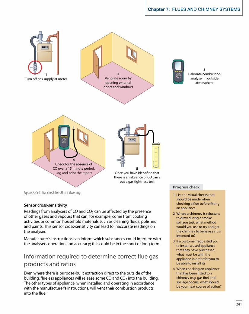
241
Chapter 7: FLUES AND CHIMNEY SYSTEMS
Sensor cross-sensitivityReadings from analysers of CO and CO2 can be affected by the presence of other gases and vapours that can, for example, come from cooking activities or common household materials such as cleaning fluids, polishes and paints. This sensor cross-sensitivity can lead to inaccurate readings on the analyser.
Manufacturer’s instructions can inform which substances could interfere with the analysers operation and accuracy; this could be in the short or long term.
Information required to determine correct flue gas products and ratiosEven where there is purpose-built extraction direct to the outside of the building, flueless appliances will release some CO and CO2 into the building. The other types of appliance, when installed and operating in accordance with the manufacturer’s instructions, will vent their combustion products into the flue.
1Turn o� gas supply at meter
3Calibrate combustion
analyser in outsideatmosphere
2Ventilate room byopening external
doors and windows
5Once you have identi�ed that
there is an absence of CO carryout a gas tightness test
4Check for the absence of
CO over a 15 minute period.Log and print the report
Figure 7.43 Initial check for CO in a dwelling1 List the visual checks that
should be made when checking a flue before fitting an appliance.
2 Where a chimney is reluctant to draw during a smoke spillage test, what method would you use to try and get the chimney to behave as it is intended to?
3 If a customer requested you to install a used appliance that they have purchased, what must be with the appliance in order for you to be able to install it?
4 When checking an appliance that has been fitted to a chimney (e.g. gas fire) and spillage occurs, what should be your next course of action?
progress check
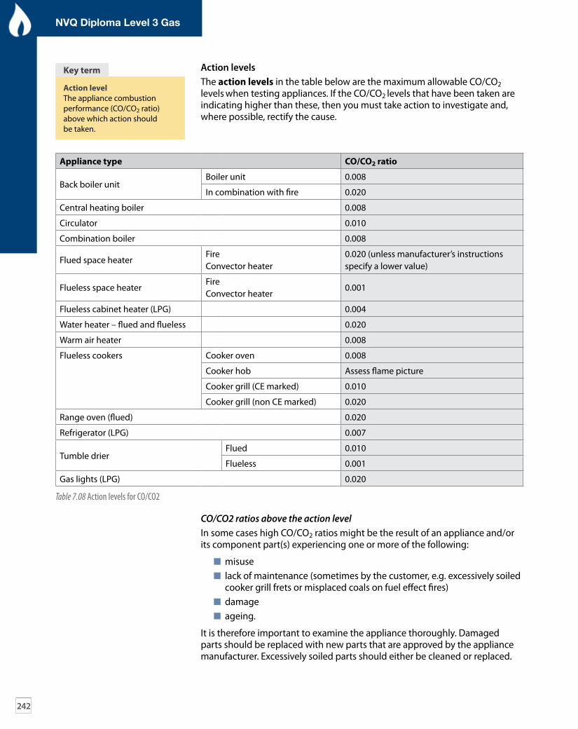
action levelThe appliance combustion performance (CO/CO2 ratio) above which action should be taken.
Key term
242
NVQ Diploma Level 3 Gas
Action levelsThe action levels in the table below are the maximum allowable CO/CO2 levels when testing appliances. If the CO/CO2 levels that have been taken are indicating higher than these, then you must take action to investigate and, where possible, rectify the cause.
CO/CO2 ratios above the action levelIn some cases high CO/CO2 ratios might be the result of an appliance and/or its component part(s) experiencing one or more of the following:
misuse lack of maintenance (sometimes by the customer, e.g. excessively soiled
cooker grill frets or misplaced coals on fuel effect fires) damage ageing.
It is therefore important to examine the appliance thoroughly. Damaged parts should be replaced with new parts that are approved by the appliance manufacturer. Excessively soiled parts should either be cleaned or replaced.
appliance type co/co2 ratio
Back boiler unitBoiler unit 0.008
In combination with fire 0.020
Central heating boiler 0.008
Circulator 0.010
Combination boiler 0.008
Flued space heaterFireConvector heater
0.020 (unless manufacturer’s instructionsspecify a lower value)
Flueless space heaterFireConvector heater
0.001
Flueless cabinet heater (LPG) 0.004
Water heater – flued and flueless 0.020
Warm air heater 0.008
Flueless cookers Cooker oven 0.008
Cooker hob Assess flame picture
Cooker grill (CE marked) 0.010
Cooker grill (non CE marked) 0.020
Range oven (flued) 0.020
Refrigerator (LPG) 0.007
Tumble drierFlued 0.010
Flueless 0.001
Gas lights (LPG) 0.020
Table 7.08 Action levels for CO/CO2

243
Chapter 7: FLUES AND CHIMNEY SYSTEMS
Re-test the appliance to confirm that the action taken has rectified the problem. Some new components will contain volatile products for which you will need to ‘burn off the newness’ before a reliable measurement of CO can be taken. Examples of volatile products on new components include:
gas fire ceramic fibre fuel effect a cooker grill fret insulation and adhesives.
The recommendation is that when a new component that has been fitted, the appliance is operated at full rate and a combustion reading is taken after 10 mins. If this reading is still unacceptable or still rising, continue sampling at 20-min intervals until a satisfactory stable level is reached or the level stabilises at an unacceptable level. For the latter, if the level does not fall within 20 mins, then a further inspection of the appliance should be made to establish the cause of the high reading.
Failure to achieve a satisfactory CO/CO2 ratioWhere it is not possible to achieve a CO/CO2 ratio at or lower than the levels in Table 7.08 or specified by the appliance manufacturer, the continued use of the appliance might constitute a danger to persons. In such circumstances, GSIUR, Regulation 34(4) states that if you are the responsible gas operative who becomes aware of an unsafe/dangerous appliance, you must take steps to inform the responsible person for the premises concerned (landlord/gas appliance owner). Where none of these persons is available or readily contactable, you must notify the gas supplier or transporter (as appropriate) to enable any necessary action to be taken to make the appliance safe. See Chapter 11 for more details. Guidance on Regulation 34 is contained in Health and Safety Commission (HSC) Approved Code of Practice and Guidance, Safety in the installation and use of gas systems and appliances.
A flued appliance that fails to achieve a satisfactory combustion ratio should be regarded as AR and a flueless appliance should be regarded as being ID as defined in the Gas Industry Unsafe Situations Procedure – see Chapter 11 for more information.
Manufacturers must give information relating to their appliances and the CO/CO2 ratios that the appliance can emit to work effectively. When new condensing boilers are fitted and commissioned, unless otherwise stated by the manufacturer, there is no need to perform a combustion analysis on the appliance.
During routine servicing of the appliance, the manufacturer’s instructions gives levels of CO/CO2. BS 7967-3: 2005 Table 1 gives values for the action levels for types of appliances and their maximum level.
Procedures for the sampling of appliances for the CO/CO2 ratioWhen sampling, always use the analyser in accordance with the manufacturer’s instructions. Where the gas appliance has a sampling point provided and a sampling procedure is given in the manufacturer’s instructions, then the checks should be carried out according to those instructions.
Where there are no specific instructions from the manufacturer, follow the procedures below for the appropriate appliance.

Figure 7.44 Standard sampling probe with moisture/filter protection
244
NVQ Diploma Level 3 Gas
Whenever sampling is in progress the position of the probe should be adjusted until the highest steady value of CO2 or the lowest steady value of O2
reading is achieved.
When using a multi-hole sampling probe take care to ensure all of the open sampling holes in the probe are positioned within the combustion products stream in order to obtain the maximum CO2 or minimum O2 reading.
The connection between the sampling probe and the analyser should only be by silicone tubing, which does not kink or flatten.
BS 7967-2 states that the CO/CO2 ratio should be recorded when the appliance or burner (whichever is applicable) has been operating at the maximum rated input for 30 mins, or when the reading is steady, or satisfactory and is decreasing; whichever is the least time unless stated differently in the appliance manufacturer’s instructions.
Satisfactory CO/CO2 are stated in Table 7.08; if the ratio is unsatisfactory then the take the appropriate action outlined in the section on ‘Checks to make where it has not been possible to check CO/CO2 ratio’ (page 249).
For many sampling applications the standard open-ended probe, which is usually supplied with the analyser, is suitable to collect a mixed and representative sample of the POC. For some applications this type of probe is not flexible or long enough to gain sufficient penetration. It is recommended that the probe is open ended and made from 6 mm (outside diameter) malleable metallic tubing approximately 500 mm in length.
To obtain a well-mixed representative sample on open-flued appliances the probe tip should be positioned at least 200 mm into the secondary flue.
When a cooker grill or cooker oven is being sampled, a multi-holed probe of the type in Figures 7.45 and 7.46 respectively should be used.
When room-sealed appliances are being tested, the sample probe should be positioned 200mm inside the combustion products outlet duct. In appliances that are fitted to se ducts or ‘u’ ducts, the air for combustion in the duct might contain variable amounts of combustion products from other appliances. Any combustion products readings cannot, therefore, be relied upon as an accurate indication of combustion performance.
Where appliances are sited for example, a room-sealed appliance installed in a block of flats and not having a purpose-designed sampling point, it will not be possible to gain access to the flow of combustion products in the flue. In such instances it will not be possible to measure the combustion products. See the section on ‘Checks to make where it has not been possible to check CO/CO2 ratio’ (page 249).
Care needs to be taken when sampling in the outlet of a fanned-flue appliance to ensure that the probe does not damage the fan.
Type A – Flueless appliancesWhen testing grills, position the probe in the combustion products stream. Wherever the appliance design allows, the probe and its position should be as shown in Figure 7.45.
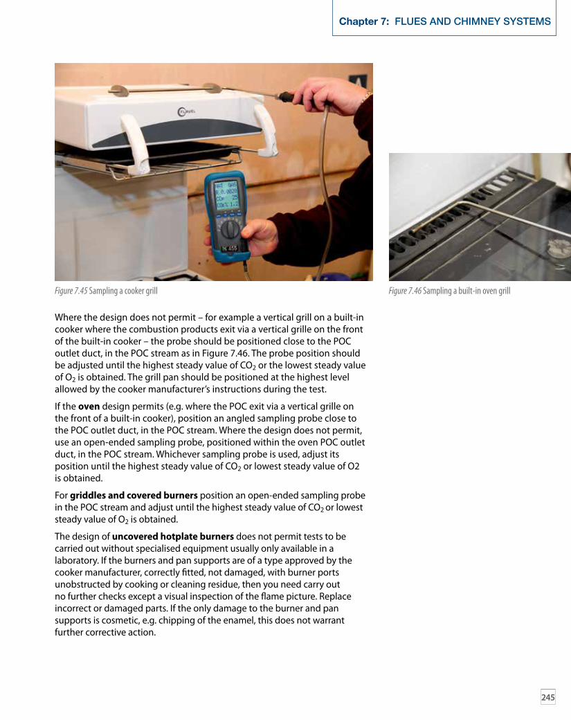
245
Chapter 7: FLUES AND CHIMNEY SYSTEMS
Where the design does not permit – for example a vertical grill on a built-in cooker where the combustion products exit via a vertical grille on the front of the built-in cooker – the probe should be positioned close to the POC outlet duct, in the POC stream as in Figure 7.46. The probe position should be adjusted until the highest steady value of CO2 or the lowest steady value of O2 is obtained. The grill pan should be positioned at the highest level allowed by the cooker manufacturer’s instructions during the test.
If the oven design permits (e.g. where the POC exit via a vertical grille on the front of a built-in cooker), position an angled sampling probe close to the POC outlet duct, in the POC stream. Where the design does not permit, use an open-ended sampling probe, positioned within the oven POC outlet duct, in the POC stream. Whichever sampling probe is used, adjust its position until the highest steady value of CO2 or lowest steady value of O2 is obtained.
For griddles and covered burners position an open-ended sampling probe in the POC stream and adjust until the highest steady value of CO2 or lowest steady value of O2 is obtained.
The design of uncovered hotplate burners does not permit tests to be carried out without specialised equipment usually only available in a laboratory. If the burners and pan supports are of a type approved by the cooker manufacturer, correctly fitted, not damaged, with burner ports unobstructed by cooking or cleaning residue, then you need carry out no further checks except a visual inspection of the flame picture. Replace incorrect or damaged parts. If the only damage to the burner and pan supports is cosmetic, e.g. chipping of the enamel, this does not warrant further corrective action.
Figure 7.45 Sampling a cooker grill Figure 7.46 Sampling a built-in oven grill

246
NVQ Diploma Level 3 Gas
An open-ended sampling probe should be used for refrigerators, positioned within the POC outlet duct, in the POC stream.
For gas lights, position the probe in the POC stream.
For fixed flueless space heaters, position the sampling probe shown in Figure 7.45 in the POC stream directly above the outlet grille. Adjust the position of the probe until the highest steady value of CO2 or lowest steady value of O2 is obtained.
mobile portable liquefied petroleum gas (lpg) heaters should be in a draught-free area and the sampling probe shown in Figure 7.45 should be positioned in the POC stream directly above the outlet grille. Adjust the position of the probe until the highest steady value of CO2 or lowest steady value of O2 is obtained.
For flueless water heaters the sampling probe shown in Figure 7.47 should be positioned in the POC stream directly above the outlet grille. Adjust the position of the probe until the highest steady value of CO2 or lowest steady value of O2 is obtained.
Type B – Open-flued appliancesThe combustion performance of open-flued appliances installed in compartments requires the POC to be sampled with the installation operating as normal, i.e. operating so that the open servicing access to the compartment does not provide a greater level of ventilation than usual. Sampling should therefore take place with any door to the compartment closed.
One method of sampling is with the tubing connected between the combustion analyser and the sampling probe in the flue, passing via permanent ventilation openings associated with the installation. You can then take the readings from outside the compartment. The general procedures to be adopted when sampling different types of appliance in compartments are those outlined below in relation to boilers and warm air heaters.
For boilers and water heaters with a draught diverter, position an open-ended sampling probe in the POC stream of the secondary flue via the draught diverter. A multi-hole sampling probe conforming to Figure 7.45 can also be used. Whichever probe is used its position should be adjusted until the highest steady value of CO2 or lowest steady value of O2 is obtained.
For boilers and water heaters without a draught diverter, place an open-ended sampling probe within the POC outlet duct and adjust its position until the highest steady value of CO2 or lowest steady value of O2 is obtained.
How the measurements are carried out for warm air heaters will depend on the flue/draught diverter configuration. Typical open-flue/draught diverter configurations for air heaters are shown in Figure 7.48 1a) to Figure 7.38 1e).
Figure 7.47 Angled sampling probe on a flueless water heater
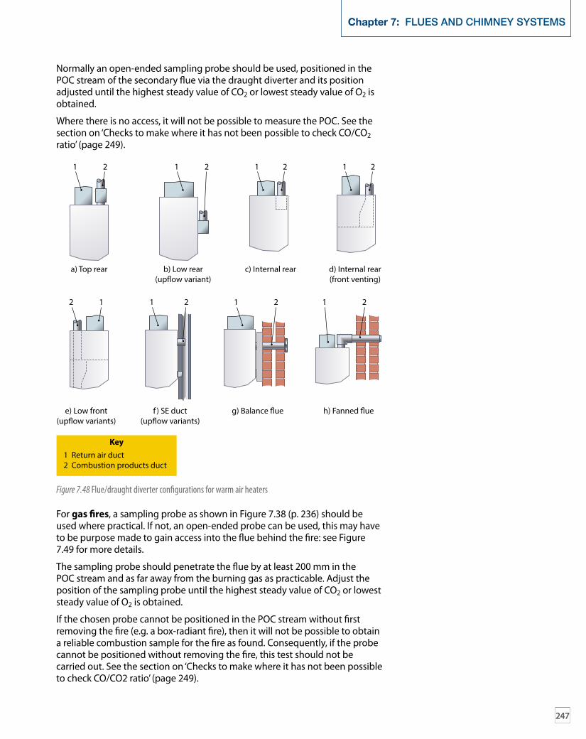
247
Chapter 7: FLUES AND CHIMNEY SYSTEMS
Normally an open-ended sampling probe should be used, positioned in the POC stream of the secondary flue via the draught diverter and its position adjusted until the highest steady value of CO2 or lowest steady value of O2 is obtained.
Where there is no access, it will not be possible to measure the POC. See the section on ‘Checks to make where it has not been possible to check CO/CO2 ratio’ (page 249).
a) Top rear
1 2
2 11 2 1 2 1 2
1 2 1 21 2
b) Low rear(up�ow variant)
c) Internal rear d) Internal rear(front venting)
e) Low front(up�ow variants)
f ) SE duct(up�ow variants)
g) Balance �ue
Key1 Return air duct2 Combustion products duct
h) Fanned �ue
Figure 7.48 Flue/draught diverter configurations for warm air heaters
For gas fires, a sampling probe as shown in Figure 7.38 (p. 236) should be used where practical. If not, an open-ended probe can be used, this may have to be purpose made to gain access into the flue behind the fire: see Figure 7.49 for more details.
The sampling probe should penetrate the flue by at least 200 mm in the POC stream and as far away from the burning gas as practicable. Adjust the position of the sampling probe until the highest steady value of CO2 or lowest steady value of O2 is obtained.
If the chosen probe cannot be positioned in the POC stream without first removing the fire (e.g. a box-radiant fire), then it will not be possible to obtain a reliable combustion sample for the fire as found. Consequently, if the probe cannot be positioned without removing the fire, this test should not be carried out. See the section on ‘Checks to make where it has not been possible to check CO/CO2 ratio’ (page 249).

248
NVQ Diploma Level 3 Gas
For combined gas fire/back boiler units (BBUs), an open-ended sampling probe should be inserted into the POC stream in the secondary flue via the draught diverter. The connecting tube to the sampling probe needs to be routed so that the fire front can be replaced without displacing the probe. The POC samples should be taken for both the boiler and the fire, when operating separately and together.
You may find it necessary to remove the outer case of the fire unit to gain access. If it is still not possible to position the sampling probe correctly when the case of the fire unit has been removed then this test cannot be carried out. See the section on ‘Checks to make where it has not been possible to check CO/CO2 ratio’ (opposite).
Type C – Room-sealed appliancesAn open-ended sampling probe should be positioned 200 mm inside the POC outlet duct and its position adjusted until the highest steady value of CO2 or lowest steady value of O2 is obtained.
Without a custom-made probe it will not be possible to gain access to the POC stream for installations of warm air heater types shown in Figure 7.48.1f ) and where, it is not advisable to attempt to do so. See the section on ‘Checks to make where it has not been possible to check CO/CO2 ratio’ (opposite).
For installations of appliance type shown in Figure 7.48.1g) access can be achieved via the terminal but only at a safe working height. This type of appliance has not been manufactured since about 1990. Room-sealed appliance types shown in Figure 7.48.1h) may have a sampling position fitted.
Chimney
Sampling probe
Radiant
Figure 7.49 Open-flued gas fire sampling

249
Chapter 7: FLUES AND CHIMNEY SYSTEMS
Checks to make where it has not been possible to check CO/CO2 ratioWhen it has not been possible to check the combustion performance ratio (CO/CO2), then the following checks should be made:
Check all disturbed gas connections. Test for gas tightness where a gas escape was previously identified/repaired.
Confirm that the burner operating pressure and/or gas rate is correct. Where possible, carry out a final combustion performance test
in accordance with the methods in BS 7967-2 to confirm that the combustion performance is within the limits allowed in BS 7967-3:2005, Clause 5.
Check the operation of any flame supervision device using the manufacturer’s approved method.
Ensure all seals or fastenings are present, in good condition and secured in accordance with the manufacturer’s instructions. Be especially vigilant with room-sealed positive fan pressure appliances. Refer to Gas Safe Register Technical Bulletin 006 of 19 August 2010, Industry guidance for the checking of case seals and the general integrity of room-sealed fan assisted positive pressure gas appliances (14).
Where appropriate for the appliance design, carry out a spillage test. Ensure any warning labels necessary to ensure safe use of the
appliance are present and correct.

250
NVQ Diploma Level 3 Gas
Knowledge check
1 Which of the following materials would not be suitable for use in constructing new open-flue chimneys?
a Concrete liners b Clay liners c Metallic pipes d Pumped or poured concrete
liners
2 When installing a gas fire, the maximum length of flue permitted in order to prevent condensation within an internal 225 mm x 225 mm brick chimney is:
a 10 m b 12 m c 28 m d 33 m
3 When installing a gas fire to an unlined brick chimney a terminal is required when the flue size is less than:
a 120 mm b 150 mm c 170 mm d 300 mm
4 A suitable method of sealing the annular (circular) space around a flexible stainless steel flue liner is to use:
a Any flexible material b Mineral wool, clamping and/or
register plate c Sand and cement d All of the above
5 When installing a gas fire and back boiler unit the chimney shall be lined if the length of the chimney exceeds:
a 12 m b 15 m c 18 m d Any length
6 Single wall flue pipe with socket joints shall be:
a Sealed with the socket of each section fitted uppermost
b Sealed using mastic jointing compound
c Sealed and the socket of each section shall be facing downwards
d Fitted with the socket of each section clipped to the wall
7 The temperature effects on pre-cast flue blocks (caused by heat from the products of combustion) should be avoided by:
a Plastering directly onto the flue blocks
b Dry lining with an air gap in front of the flue blocks
c Using plasterboard with the supporting dabs in direct contact with the flue block
d Screwing the plasterboard to the flue block
8 Which of the following might lead to incomplete combustion?
a Poor flueing b A blocked heat exchanger c A blocked primary air port d All of the above
9 What are the symptoms associated with carbon monoxide poisoning?
a Severe abdominal pains b Headaches, nausea and
dizziness c Soreness of joints and muscles d All of the above
10 Products of incomplete combustion, including CO leaking from an appliance, might be found:
a In the location of the appliance b In adjoining rooms c Migrating into other properties d In all of the above
11 When testing the combustion performance of an open-flue boiler the analyser sensing probe should be:
a 200 mm into the primary flue b 200 mm into the secondary flue c 200 mm into the draught diverter d Inside of the terminal
12 What immediate advice should be given to someone suffering from the symptoms of carbon monoxide poisoning?
a Leave the room and close all internal doors
b Call a service engineer c Get out of the building and into
fresh air d Turn off the appliance and take
headache tablets
13 In accordance with BS7967 Part 3 what is the maximum CO/CO2 ratio permitted for a flueless space heater?
a 0.004 b 0.008 c 0.001 d 0.01
14 In accordance with BS7967 Part 3 what is the maximum CO/CO2 ratio permitted for a combination boiler?
a 0.004 b 0.008 c 0.001 d 0.01
15 When a flueless space heater is tested and the CO/CO2 ratio is exceeded, what action should you take?
a None b Classify the appliance as ‘at risk’
(AR) c Classify the appliance as ‘not to
current standards’ (NCS) d Classify the appliance as
‘immediately dangerous’ (ID)