FLT93-S - Gilson Eng · TheFLT®93SerieswithFlexSwitch® Technology...
8
Mounting Reference “U”- Length “U”–length Mounting Reference .63 (16) Max Reference Sensor Active Sensor & Heater Reference Sensor FLT93-S (Extended “U” - Length 3/4'' NPT Configuration Shown) REF 1 inch NPT Customer Conduit Port E a 4.73 (120.2) 1.50± .50 (38.1± 12.7) FLT93-F (Extended “U” - Length 3 _ 4 '' NPT Configuration Shown) .50 (12.7) 1.85 (47) 4.30 (109 Enclosure used as junction box or to Assembly certifie Class I Division Class II Divisio NEMM type 4 (meets IP65 Active Sensor & Heater “U”- Length Chassis Ground Lug “U”–length Mounting Reference Max Sensor FLT93-S - Length 3/4'' NPT Configuration Shown) REF 1 inch NPT Customer Conduit Port External Ground Lug and Cover Lock provided on CENELEC approved enclosure 4.73 (120.2) 1.50± .50 (38.1± 12.7) -F PT Configuration Shown) 1.85 (47) 4.63 (117.6) 2.06 (52.3) 4.30 (109.2) Available wet 316 stainless Monel 400 Hastelloy C276 Titanium (type “S”only) Available “U” lengths: 0.9 inch (23) (“F” type only) 1.2 inch (31) (“S” type only) 2.0 inch (51) 4.0 inch (102) 6.0 inch (152) 9.0 inch (229) 12.0 inch (305) 18.0 inch (457) (meets I Chassis Ground Lug “U”–length guration Shown) 1 inch NPT Customer Conduit Port External Ground Lug and Cover Lock provided on CENELEC approved enclosure 4.73 (120.2) 1.50± .50 (38.1± 12.7) n) 1.85 (47) 4.63 (117.6) 2.06 (52.3) 4.30 (109.2) Available wetted surface material of construction: 316 stainless steel Monel 400 Hastelloy C276 Titanium (type “S”only) Available “U” lengths: 0.9 inch (23) (“F” type only) 1.2 inch (31) (“S” type only) 2.0 inch (51) 4.0 inch (102) 6.0 inch (152) 9.0 inch (229) 12.0 inch (305) 18.0 inch (457) Enclosure used as wire terminal junction box or to house local switch electronics. Assembly certified to: Class I Division 1&2 groups B, C & D Class II Division 1 groups E, F & G NEMM type 4x and/or EEx dII (meets IP65 or 66) Mounting Reference “U”- Length Chassis Ground Lug “U”–length Mounting Reference .63 (16) Max Reference Sensor Active Sensor & Heater Reference Sensor FLT93-S (Extended “U” - Length 3/4'' NPT Configuration Shown) REF 1 inch NPT Customer Conduit Port External Ground Lug and Cover Lock provided on CENELEC approved enclosure 4.73 (120.2) 1.50± .50 (38.1± 12.7) FLT93-F (Extended “U” - Length 3 _ 4 '' NPT Configuration Shown) .50 (12.7) 1.85 (47) 4.63 (117.6) 2.06 (52.3) 4.30 (109.2) Available wetted surface material of constructio 316 stainless steel Monel 400 Hastelloy C276 Titanium (type “S”only) Available “U” lengths: 0.9 inch (23) (“F” type only) 1.2 inch (31) (“S” type only) 2.0 inch (51) 4.0 inch (102) 6.0 inch (152) 9.0 inch (229) 12.0 inch (305) 18.0 inch (457) Enclosure used as wire terminal junction box or to house local switch electronics. Assembly certified to: Class I Division 1&2 groups B, C & D Class II Division 1 groups E, F & G NEMM type 4x and/or EEx dII (meets IP65 or 66) Active Sensor & Heater Available wetted surface m 316 stainless steel Monel 400 Hastelloy C276 Titanium (type “ Enclosure used as wire terminal junction box or to house local switch electronics. Assembly certified to: Class I Division 1&2 groups B, C & D Class II Division 1 groups E, F & G NEMM type 4x and/or EEx dII (meets IP65 or 66) Chassis Ground Lug External Ground Lug and Cover Lock ded on 1.85 (47) 4.63 (117.6) 4.30 (109.2) Mounting Reference Active Sensor & Heater .50 (12.7) Active Sensor & Heater .50 (12.7) Mounting Reference “U”- Length Chassis Ground Lug REF 4.73 (120.2) 1.50± .50 (38.1± 12.7) 1.85 (47) 4.63 (117.6) 4.30 (109.2) FLOW TEMP LEVEL FLOW TEMP FCI FlexSwitch ® FLT ® Series: The Flow, Level, Interface and Temperature Switch with Analog Outputs and FlexSwitch Technology. FCI FLT ® SERIES ® FLT93-S NOW – FLT93 Series is SIL-2 Compliant
Transcript of FLT93-S - Gilson Eng · TheFLT®93SerieswithFlexSwitch® Technology...
Mounting
Reference“U”- Length
“U”–length
Mounting
Reference
.63 (16) Max
Reference Sensor
Active Sensor
& Heater
Reference Sensor
FLT93-S
(Extended “U” - Length 3/4'' NPT Configuration Shown)
REF
1 inch NPT
Customer Conduit PortEa
4.73 (120.2)1.50± .50 (38.1± 12.7)
FLT93-F
(Extended “U” - Length3_4 '' NPT Configuration Shown)
.50 (12.7)
1.85 (47)
4.30(109
Enclosure used as
junction box or to
Assembly certifie
Class I Division
Class II Divisio
NEMM type 4
(meets IP65
Active Sensor
& Heater
“U”- Length
ChassisGroundLug
“U”–length
Mounting
Reference
Max
SensorFLT93-S
- Length 3/4'' NPT Configuration Shown)
REF
1 inch NPT
Customer Conduit PortExternal Ground Lug
and Cover Lock
provided on
CENELEC
approved enclosure
4.73 (120.2)1.50± .50 (38.1± 12.7)
-FPT Configuration Shown)
1.85 (47)
4.63 (117.6)
2.06(52.3)
4.30(109.2)
Available wet316 stainless
Monel 400
Hastelloy C276
Titanium (type “S”only)
Available “U” lengths:
0.9 inch (23) (“F” type only)
1.2 inch (31) (“S” type only)
2.0 inch (51)
4.0 inch (102)
6.0 inch (152)
9.0 inch (229)
12.0 inch (305)
18.0 inch (457)
(meets I
ChassisGroundLug
“U”–length
guration Shown)
1 inch NPT
Customer Conduit PortExternal Ground Lug
and Cover Lock
provided on
CENELEC
approved enclosure
4.73 (120.2)1.50± .50 (38.1± 12.7)
n)
1.85 (47)
4.63 (117.6)
2.06(52.3)
4.30(109.2)
Available wetted surface material of construction:
316 stainless steel
Monel 400
Hastelloy C276
Titanium (type “S”only)
Available “U” lengths:
0.9 inch (23) (“F” type only)
1.2 inch (31) (“S” type only)
2.0 inch (51)
4.0 inch (102)
6.0 inch (152)
9.0 inch (229)
12.0 inch (305)
18.0 inch (457)
Enclosure used as wire terminal
junction box or to house local switch electronics.
Assembly certified to:
Class I Division 1&2 groups B, C & D
Class II Division 1 groups E, F & G
NEMM type 4x and/or EEx dII
(meets IP65 or 66)
Mounting
Reference“U”- Length
ChassisGroundLug
“U”–length
Mounting
Reference
.63 (16) Max
Reference Sensor
Active Sensor
& Heater
Reference Sensor
FLT93-S
(Extended “U” - Length 3/4'' NPT Configuration Shown)
REF
1 inch NPT
Customer Conduit PortExternal Ground Lug
and Cover Lock
provided on
CENELEC
approved enclosure
4.73 (120.2)1.50± .50 (38.1± 12.7)
FLT93-F
(Extended “U” - Length3_4 '' NPT Configuration Shown)
.50 (12.7)
1.85 (47)
4.63 (117.6)
2.06(52.3)
4.30(109.2)
Available wetted surface material of constructio
316 stainless steel
Monel 400
Hastelloy C276
Titanium (type “S”only)
Available “U” lengths:
0.9 inch (23) (“F” type only)
1.2 inch (31) (“S” type only)
2.0 inch (51)
4.0 inch (102)
6.0 inch (152)
9.0 inch (229)
12.0 inch (305)
18.0 inch (457)
Enclosure used as wire terminal
junction box or to house local switch electronics.
Assembly certified to:
Class I Division 1&2 groups B, C & D
Class II Division 1 groups E, F & G
NEMM type 4x and/or EEx dII
(meets IP65 or 66)
Active Sensor
& Heater
Available wetted surface m
316 stainless steel
Monel 400
Hastelloy C276
Titanium (type “
Enclosure used as wire terminal
junction box or to house local switch electronics.
Assembly certified to:
Class I Division 1&2 groups B, C & D
Class II Division 1 groups E, F & G
NEMM type 4x and/or EEx dII
(meets IP65 or 66)
ChassisGroundLug
External Ground Lug
and Cover Lock
ded on
1.85 (47)
4.63 (117.6)
4.30(109.2)
Mounting
Reference
Active Sensor
& Heater
.50 (12.7)
Active Sensor
& Heater
.50 (12.7)
Mounting
Reference“U”- Length
ChassisGroundLug
REF
4.73 (120.2)1.50± .50 (38.1± 12.7)
1.85 (47)
4.63 (117.6)
4.30(109.2)
FLOW
TEMP
LEVEL
FLOW
TEMP
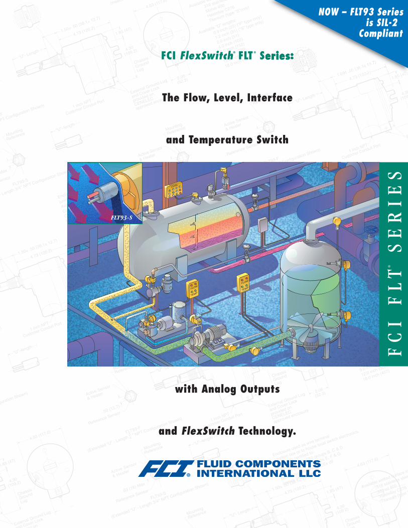
FCI FlexSwitch® FLT® Series:
The Flow, Level, Interface
and Temperature Switch
with Analog Outputs
and FlexSwitch Technology.
FCI
FLT®
SERIES
®
FLT93-S
NOW – FLT93 Seriesis SIL-2
Compliant

The FLT®93 Series with FlexSwitch® TechnologyFCI’s FLT93 Series Switches with FlexSwitch technology representthe first true technological advance in flow, level, and temperaturesensing and switching in over a decade. A single instrument, easilyfield-configured or factory preset, provides unparalleled accuracy,flexibility, and stability for most flow, level, and temperature sensingand switching needs.
Standardization This sensing and switching breakthrough isachieved in the FLT93 Series Switches by combining a new, highlyaccurate, all-welded sensing element with an advanced, user-friendlyFlexSwitch control circuit.Sensing Element. Two standard sensing element configurations areavailable to meet your most demanding application requirements.The FLT93-S is designed for use in standard heavy industrial applica-tions and in applications with high velocity liquid setpoint require-ments; the FLT93-F is designed for fast response gas applications.Both sensing elements can be supplied in either standard (-40°to +350°F [-40° to +177°C]) or medium (-100° to +500˚F [-73° to+260°C]) temperature configurations. The FLT93-S is also available ina high temperature (-100° to +850°F [-73° to +454°C]) configuration.Control Circuit. One standardized, field-configurable FlexSwitch
Sensing Element Feature Highlights� No moving parts� All welded design� Exotic materials
FLT93-S�Designed for heavy industrialenvironments
�High liquid flow rate sensitivity�High temperature service� Retractable packing glands
FLT93-F� Faster response� Small process connection
Control Circuit Feature Highlights� Temperature compensation� Analog output voltage for flow and temperature� Calibration mode switch to simulate alarm setpoint� Fail-safe setup� Dual alarm, each with SPDT relay/ DPDT optional� Field selected input power
Rack or Socket Mounted Control Circuit Electronics
control circuit satisfies virtually any combination of applicationrequirements. The FlexSwitch technology can be packaged to meetmost integral, remote, and rack mounted configurations.
Precise Performance Accuracy Leveraged from FCI’s field-proven thermal dispersion experience, the unique sensor technologyof the FLT93 Series Switches, combined with FlexSwitch tempera-ture compensation circuitry, introduces unparalleled performancecapabilities:� Exclusive flow accuracy as precise as ±2% of the setpointvelocity over a ±50°F [±28°C] temperature range;repeatability of ±0.5% reading.� Level resolution of ±0.1 inch [±0.5 cm]; repeatability of±0.05 inch [±0.3 cm].� Standard temperature accuracy ±2.0°F [±1°C]; repeatability±1.0˚F [±0.6˚C]. Improved temperature accuracy is availablewith factory calibration.
Integrated Technologies–Advanced FlexSwitch CircuitryAvailable in both standard socket mount or optional rack mountconfigurations, FCI’s fail-safe, dual alarm (SPDT) control circuitprovides the FLT93 Series Switches with unmatched field flexibilityand user-friendliness. The FlexSwitch control circuit also providesthe exclusive advantage of one switch that offers the following field-selectable features:� Dual, independent SPDT relays for the following alarmcombinations:– Flow rate and temperature– High flow and low flow– Point level and temperature– Flow rate and low liquid level– Three-phase level interface– Fail-safe flow, level, or temperature
�One DPDT relay for single alarm of flow rate, liquid level ortemperature is optionally selectable
Application FlexibilityEasy Field or Factory Preset Configurations. FlexSwitch circuitfeatures are easily enabled and can be selected either in-situ orfactory preset. Selections include the following:
FLT93-F and FLT93-S Sensing Elements
FLT93-S and FLT93-F Insertion FlexSwitch

Accuracy and Temperature Compensation FLT93 Seriesswitches are “precision temperature compensated” to insurethe accuracy of factory and field set alarms when installedin dynamic process applications. Accuracy combined withtemperature compensation results in:
� Preventing false alarms or alarm failure� Maximizing operator and process safety� Having the option to set alarms within a narrow set point range
The “Temperature Compensated Flow Curves” graph (right)illustrates how “temperature compensated” flow switches willnot experience signal drift during temperature changes. Whereasa “non-temperature compensated” flow switch experiences signaldrift (as indicated by the red arrow) causing alarm failure.
Typical Monitoring Applications� High/ low pump flow� Relief valve and flare gas flow or leakage detection� HVAC flow monitoring� Monitoring heat exchanger and filter fouling� Drain line flow detection� Pump seal leak and lubricant detection� Wet /dry and sump seal detection� High/ low level alarm and control� Interface control in separation vessels� High and low temperature alarm
FLT93-C Sanitary Sensing Element
Outp
utSi
gnal
(DC
volts
)
0
1
7
6
5
4
3
2
DetergentFoam Demineralizer/
Resin SlurryDiesel
KeroseneWater
30 wt.Oil
AirNote: Output signal will vary with heater power selection.
Typical Level and Interface Output Signals
Flow Ranges for FLT93S, FLT93F, or FLT93C
.001 .01 .1 1 10 100 1000Velocity (ft./sec.) For meters per second, multiply by 0.3048
Water-Based Liquids
Hydrocarbon-Based Liquids
Gases
2.00
1.75
1.50
1.25
1.00
0.75
Volta
geOu
tput
,Vdc
0 1 2 3 4 5Velocity (ft./sec.) For meters per second, multiply by 0.3048
51˚F [10.6˚C]76˚F [24.4˚C]
139˚F [59.4˚C]
signal stability with temperature compensation
signal driftwithout temperature
compensation
Temperature Compensated Flow Curves
3
1
Outp
utSi
gnal
(DC
volts
)
2
0.01 0.1 1 10
30 wt. Oil
Water
Velocity (ft./sec.) For meters per second, multiply by 0.3048
Typical Liquid Flow Curves
Delivering the same field-tested performanceand reliability as the FLT93-S and F, The FLT93-Cis built to comply with the stringent 3A Sanitaryand general sanitary requirements of the Food,Beverage, Pharmaceutical and Chemical indutries.
The instrument’s no moving parts designmakes it ideal for monitoring the flow of syrups,fillings and other viscous media and productslurries. The FLT93-C is suitable for bothclean-in-place and steam-in-place applications.
Control Circuit Feature Highlights� Refer to FLT93-F and S on previous page
Common Applications� Pump protection� Additive verification� Gas/steam injection monitoring� Analyzer flow monitoring� Syrup flow monitoring� Low flow detection� Level /Interface
FLT93-C Sanitary Insertion FlexSwitch
Field Selectable Feature Advantage/Benefit
Input Power Jumpers Maximizes voltage source flexibilityand emergency power operations.
Application/Heater Power Optimizes signal level or bestconfiguration for changing appli-cation conditions.
Relay Configuration Enables easy field selection ofSPDT or DPDT configurationsand relay energization modes.
Calibrate /Operate Mode Selects field verification, pre-check,calibration or general operationmodes.
Maximized Instrument Life Simple reconfiguration allowsthe instrument to be further utilized in new service applications oreasily adjusted as specific application requirements change.
Simple, Accurate, Field Set Alarms Field calibrations and set-point adjustments are easily performed. Voltage readings at criticalsetpoint values can easily be recorded for reference purposes orfor optimized monitoring.
Field Selectable Input Power The FLT93 Series’ FlexSwitchcircuit is field configurable for compatibility with the most common-electrical power. Selection of 24 Vdc, 115 Vac or 230 Vac bysimple jumper selection is a standard feature.
CalibrationSwitch
SensingElement
ReferenceRTD
ActiveRTD
Heater
Input Power
1
2
3
5
4
1
2
3
5
4Out +Out -
Temp +Temp -
9
87
10
12
1234
6 NC2
4 NO2
5 COM2
11 NC1
12 NO1
3 COM1
Flow/Level orTemperatureSelector
Alarm Setpoint 2Adjustment
SensorCurrentSource
SignalConditioner
Heater PowerSelector/Temp Control
PowerSupply &Selector
Temp CompAdjustment
CalibrationAdjustment
Alarm Setpoint 1Adjustment
5294 Control Circuit Functional Diagram
Selection Jumpers
and Logic Jumpers
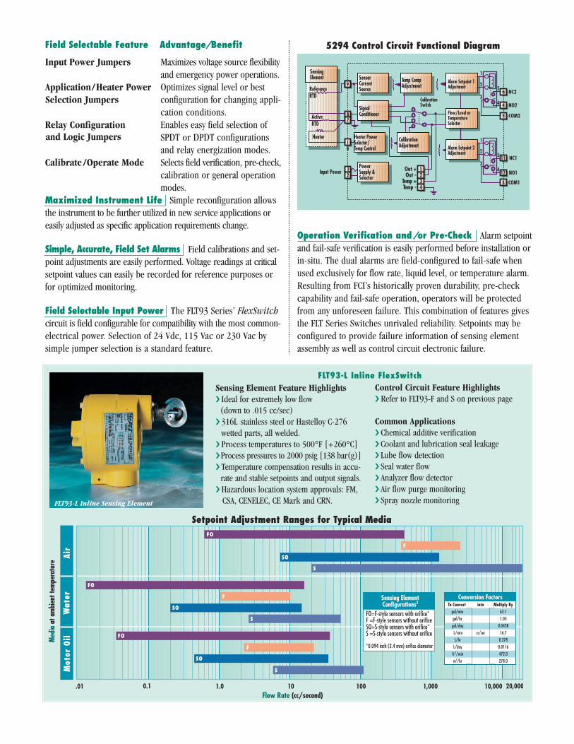
FLT93-L Inline Sensing Element
Operation Verification and/or Pre-Check Alarm setpointand fail-safe verification is easily performed before installation orin-situ. The dual alarms are field-configured to fail-safe whenused exclusively for flow rate, liquid level, or temperature alarm.Resulting from FCI’s historically proven durability, pre-checkcapability and fail-safe operation, operators will be protectedfrom any unforeseen failure. This combination of features givesthe FLT Series Switches unrivaled reliability. Setpoints may beconfigured to provide failure information of sensing elementassembly as well as control circuit electronic failure.
.01 0.1 1.0 10 100 1,000 10,000Flow Rate (cc/second)
FO
F
SO
FO
F
SO
S
FO
F
SO
SMot
orO
ilAi
rW
ater
20,000
To Convertgal/mingal/hr
gal/dayL/minL/hrL/day
ft3/minm3/hr
S
Med
iaat
ambi
entt
empe
ratu
re
Conversion FactorsMultiply By
63.11.05
0.043816.7
0.2780.0116472.0278.0
into
cc/sec
Sensing ElementConfigurations2
FO=F-style sensors with orifice*F =F-style sensors without orificeSO=S-style sensors with orifice*S =S-style sensors without orifice
*0.094 inch (2.4 mm) orifice diameter
gal/min
gal/day
L/hr
ft 3/min
Setpoint Adjustment Ranges for Typical Media
Sensing Element Feature Highlights� Ideal for extremely low flow(down to .015 cc/sec)
� 316L stainless steel or Hastelloy C-276wetted parts, all welded.
� Process temperatures to 500°F [+260°C]�Process pressures to 2000 psig [138 bar(g)]� Temperature compensation results in accu-rate and stable setpoints and output signals.
� Hazardous location system approvals: FM,CSA, CENELEC, CE Mark and CRN.
Control Circuit Feature Highlights� Refer to FLT93-F and S on previous page
Common Applications� Chemical additive verification� Coolant and lubrication seal leakage� Lube flow detection� Seal water flow� Analyzer flow detector� Air flow purge monitoring� Spray nozzle monitoring
FLT93-L Inline FlexSwitch

ApplicationFlow rate and /or level / interface and temperature sensing in liquid,gas and slurry applications.
Sensing Elements� Process ConnectionModels S and F
3/4 inch male NPT standard; optional 1 inch BSP, 1 inch maleNPT, 3/4 inch Male NPT (FLT93-F only); flanges, spool pieces,sanitary fittings or retractable sensing element optional.
Model L1 inch male NPT or 3/4 inch female NPT, both ends with orifice;flanges optional.
Model CSanitary flange
� Insertion LengthModels S and F
Available in standard lengths of 1.2 inch [30 mm], 2 inches[51 mm], 4 inches [102 mm], 6 inches [152 mm], 9 inches[229 mm], 12 inches [305 mm], 18 inches [457 mm] andcustom-specified lengths.
Model L3.375 inch [86 mm] in-line body length
Model CPlease see chart on outline dimensional.
� Sensing ElementModels S and F
All wetted surfaces are 316L stainless steel with all-weldedconstruction. Hastelloy C, Monel 400, electro-polishedstainless steel and titanium (FLT93-S only) are optionallyavailable. Other spray coatings are available on specialrequest (i.e., tantalum, chromium carbide).
Model LAll wetted surfaces are 316L stainless steel with all-weldedconstruction. Hastelloy C, Monel 400 and titanium areoptionally available.
Model CAll wetted surfaces are 316L stainless steel with all-weldedconstruction electro-polished to 20 Ra.
� Operating TemperatureSensing Element:All Models
Standard temperature configuration:-40° to +350°F [-40° to +177°C]Medium temperature configuration:-100° to +500°F [-73° to +260°C]
Model S OnlyHigh temperature configuration:-100° to +850°F [-73° to +454°C]
Control Circuit:All Models
Ambient -40° to +140°F [-40° + 60°C]
� Operating PressureModels S, F and L
Hydrostatically proof pressure tested to 3500 psig [241 bar(g)]at 70°F [21°C]. Derated with temperature, the maximumrecommended operation service is 2350 psig [162 bar(g)] at500°F [260°C].
Model CTo 2000 psig [138 bar(g)]
Higher ratings available with special construction and test certification.
Control Circuit Features� Control CircuitAvailable in both standard socket mount, single channel, dual alarm,epoxy sealed relays and in rack mounted configurations (card cageor enclosure not included).
� Output SignalAnalog DC voltage related to flow or level / interface signal andproportional to temperature, standard.
� Input PowerField selected or pre-configured in the factory to 115 Vac (±15),230 Vac (±30, 50 to 60 Hz), 24 Vdc (+4, -3) or 24 Vac (+2, -6);100 Vac ±10 optionally available. LED indicates power on.
� Power ConsumptionAC units, 13 VA maximum; DC units, 7 watts maximum.
� Heater PowerField or factory selected to optimize switching performance and range-ability and selectable for specific fluid service requirements. 7 wattspower consumption, 230 mA maximum.
The above typical service power selections are for reference only.Depending on application requirements, surface temperature ratingrequirements, and rangeability expectations, alternate power selectionsmay be recommended. Other intermediate power selections can bemade. Consult installation manual for recommendations in your service.
� Relay RatingDual SPDT or single DPDT field configurable 6 amp resistive at 115Vac, 240 Vac or 24 Vdc; hermetically sealed relay configurationsoptionally available.
� Electrical EnclosureAluminum (epoxy coated) or optional stainless steel. Enclosures arerated for hazardous location use (Class I and II, Division 1 and 2,Group B, C, D, E, F and G; and EEx d IIC) and resists the effect ofweather and corrosion (NEMA and CSA Type 4X and equivalent to IP66).
FlexSwitch FLT93 Series General Specifications
[specifications continued on next page]
Typical Service Sensing Element Power (W)Gas or Air S-Style 0.75
F-Style 0.25Liquids S-Style 3.0
For Flow Service� Setpoint RangeModel S
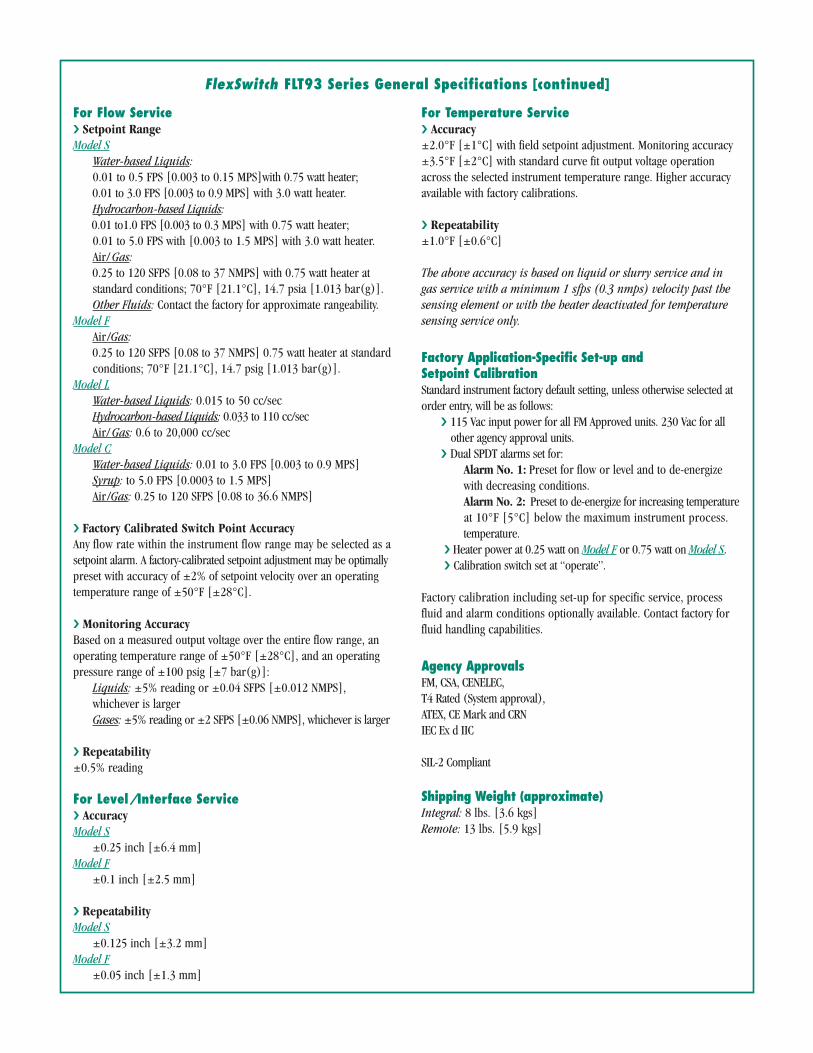
Water-based Liquids:0.01 to 0.5 FPS [0.003 to 0.15 MPS]with 0.75 watt heater;0.01 to 3.0 FPS [0.003 to 0.9 MPS] with 3.0 watt heater.Hydrocarbon-based Liquids:0.01 to1.0 FPS [0.003 to 0.3 MPS] with 0.75 watt heater;0.01 to 5.0 FPS with [0.003 to 1.5 MPS] with 3.0 watt heater.Air/Gas:0.25 to 120 SFPS [0.08 to 37 NMPS] with 0.75 watt heater atstandard conditions; 70°F [21.1°C], 14.7 psia [1.013 bar(g)].Other Fluids: Contact the factory for approximate rangeability.
Model FAir/Gas:0.25 to 120 SFPS [0.08 to 37 NMPS] 0.75 watt heater at standardconditions; 70°F [21.1°C], 14.7 psig [1.013 bar(g)].
Model LWater-based Liquids: 0.015 to 50 cc/secHydrocarbon-based Liquids: 0.033 to 110 cc/secAir/Gas: 0.6 to 20,000 cc/sec
Model CWater-based Liquids: 0.01 to 3.0 FPS [0.003 to 0.9 MPS]Syrup: to 5.0 FPS [0.0003 to 1.5 MPS]Air/Gas: 0.25 to 120 SFPS [0.08 to 36.6 NMPS]
� Factory Calibrated Switch Point AccuracyAny flow rate within the instrument flow range may be selected as asetpoint alarm. A factory-calibrated setpoint adjustment may be optimallypreset with accuracy of ±2% of setpoint velocity over an operatingtemperature range of ±50°F [±28°C].
� Monitoring AccuracyBased on a measured output voltage over the entire flow range, anoperating temperature range of ±50°F [±28°C], and an operatingpressure range of ±100 psig [±7 bar(g)]:
Liquids: ±5% reading or ±0.04 SFPS [±0.012 NMPS],whichever is largerGases: ±5% reading or ±2 SFPS [±0.06 NMPS], whichever is larger
� Repeatability±0.5% reading
For Level/Interface Service� AccuracyModel S
±0.25 inch [±6.4 mm]Model F
±0.1 inch [±2.5 mm]
� RepeatabilityModel S
±0.125 inch [±3.2 mm]Model F
±0.05 inch [±1.3 mm]
For Temperature Service� Accuracy±2.0°F [±1°C] with field setpoint adjustment. Monitoring accuracy±3.5°F [±2°C] with standard curve fit output voltage operationacross the selected instrument temperature range. Higher accuracyavailable with factory calibrations.
� Repeatability±1.0°F [±0.6°C]
The above accuracy is based on liquid or slurry service and ingas service with a minimum 1 sfps (0.3 nmps) velocity past thesensing element or with the heater deactivated for temperaturesensing service only.
Factory Application-Specific Set-up andSetpoint CalibrationStandard instrument factory default setting, unless otherwise selected atorder entry, will be as follows:
� 115 Vac input power for all FM Approved units. 230 Vac for allother agency approval units.
� Dual SPDT alarms set for:Alarm No. 1: Preset for flow or level and to de-energizewith decreasing conditions.Alarm No. 2: Preset to de-energize for increasing temperatureat 10°F [5°C] below the maximum instrument process.temperature.
� Heater power at 0.25 watt on Model F or 0.75 watt on Model S.� Calibration switch set at “operate”.
Factory calibration including set-up for specific service, processfluid and alarm conditions optionally available. Contact factory forfluid handling capabilities.
Agency ApprovalsFM, CSA, CENELEC,T4 Rated (System approval),ATEX, CE Mark and CRNIEC Ex d IIC
SIL-2 Compliant
Shipping Weight (approximate)Integral: 8 lbs. [3.6 kgs]Remote: 13 lbs. [5.9 kgs]
FlexSwitch FLT93 Series General Specifications [continued]

U-Length
EarthGrounding
Lug
REF
1 inch Female NPT Customer Conduit Port External ground lug
and cover lockprovided onCENELECapproved enclosure
4.73 [120]1.50± .50 [38 ±13]
1.85 [47]
4.63 [118]
2.06[52]
4.30[109]
Enclosure used as wire terminaljunction box or to house localswitch electronics.Instrument certified to:Class I, Division 1 and 2, Groups B, C and DClass II, Division 1, Groups E, F and GNEMA and CSA Type 4X (equivalent to IP66)and/or EEx d IIC. T4 (or T3a) rated.
REF ”“
Reference RTD
Available wetted surfacematerial of construction:316 stainless steelMonel 400Hastelloy CTitanium (“S” configurationonly)Available U-lengths:1.2 inch [30]2.0 inch [51]4.0 inch [102]6.0 inch [152]9.0 inch [229]12 inch [305]18 inch [457]
MountingReference
.63 [16] Max
FLT93-S(Extended U-Length 3/4 inch Male NPT
Configuration Shown)
Active RTDand Heater
0.875 [22] OD
Note 31" Male MNPTLocal Enclosure (see FLT-S above)
4.30[109]
Cable PIigtail
4.73[120]
Ø .156 Thru[4]
1 Inch FemaleNPT Customer
Conduit Port
or
FLOW
.75 Inch Male NPT
1 Inch Male NPTOpptionalBoth Ends1.750
[44]Max
.75 Inch Female NPTOptional Both Ends 1 Inch SCH 160 Pipe
3.375 [86] MAX(A - Length)
[millimeters]
Notes:1. For best performance, the sensing element should beinstalled into a vertical section of pipe. Liquids should flowup through the sensing element and gases should flowdown through the sensing element.
2. The time response of the F-style sensors is faster thanthe S-style sensors. However, the S-style sensors canwithstand higher fluid forces (drag) than the F-style sensors.
3. Refer to the FlexSwitch product brochure(Doc. No. 02MK011288) for additional information andcomplete specifications.
4. Use the Model FLT93L Ordering Information Sheet (OISDoc. No. 01SA011426) to configure the complete instrumentpart number.
5. Sensing element A-length is 12.0 inches (305 mm) ifflanges are specified for the process connection.
Other end connections available.
EarthGround
ø4.63[118]
ø2.06[52]
Local Enclosure Meets Explosion Proof(See FLT93-S above)
C
F
C/2
DEU Length
4.83[123]
4.30[109]
Flat IndicatesFlow Direction
1 Inch Female NPT Port
Clamp
Gasket(Customer)
Approx 1/16Except 3/4”
SIZE=D
BTube &FlangeSize
Short Leg Tee(Optional)
A Tube & FlangeSize
A B C D E F U-Lgth
111/2
21/34
11 1/
2222
5.254.755.507.005.686.188.12
1.121.061.371.621.872.122.62
1.502.122.122.122.122.122.12
N.A.1.501.752.002.252.503.00
1.431.251.931.931.932.752.75
To Convert To Millimeters Multiply by 25.4
1 2/
3/4 3/4
1 2/
1 2/
FLT93-S and FLT93-F FlexSwitch, Insertion
FLT93-L FlexSwitch, Inline
FLT93-C FlexSwitch, Sanitary Insertion

Doc. No. 02MK011288N©Copyright 2008 by Fluid Components International LLC. All rights reserved. Subject to change without notice.0407 5K
Test and Calibration Laboratory Fluid ComponentsInternational maintains an extensive, instrument test and calibrationlaboratory at its headquarters in San Marcos, California. Utilizingthe latest in advanced, computerized data acquisition systems andcalibration test equipment, this facility permits comprehensive prod-uct development, testing, and calibration. Any FCI product can becalibrated in accordance with customer specifications. Laboratorystandards are maintained with NIST (National Institute of Standardsand Technology) traceable Cavitating Venturis (CVs) and preciselycalibrated, pressure and temperature corrected turbine flowmeters.
Combustible and non-combustible gas calibration flow standsallow for the calibration of FCI products in a wide range of gasesand gas mixtures in flow stand line sizes as small as 1/8 inch to30 inches [3 to 760 mm] in diameter. A variety of flow profiles
from laminar to turbulent conditions are generated to duplicateactual field conditions. Flow rates from 0 to 20,000+ SCFM [0 to34,000 NCMH], velocities from 0 to 800 SFPS [0 to 240 NMPS],pressures from vacuum to 3000 psig [200 bar(g)], and tempera-tures from -100º to +900ºF [-70º to +480ºC] are available.
On-Site Calibration and Training In-situ calibration is avail-able from FCI’s Field Service engineers where precise test andcalibration is accomplished in actual media conditions.
FCI’s Training Department can provide on-site or at the factoryProduct Knowledge Workshops for our customers. The work-shops cover installation, setup, and troubleshooting skills, andinclude hands-on exercises using real products, under actualoperating conditions.
24 Hour Customer Service Access Available
Web: www.fluidcomponents.com1755 La Costa Meadows Drive, San Marcos, California 92078 USA | Phone: 760-744-6950 | Toll free: 800-854-1993 | Fax: 760-736-6250
European Office: Persephonestraat 3-01 5047 TT Tilburg, The Netherlands | Phone: 31-13-5159989 | Fax: 31-13-5799036ISO 9001:2000 and AS9100 certified