FLT-04 User Manual v1.0
10
Contents Caution Specifications Dimensional Drawing Components Assembly Setup Operation/Reset Procedure Troubleshooting Model: FLT-04 User Guide 1 2 3,4 5 6 7 8 9
Transcript of FLT-04 User Manual v1.0

Contents
Caution Specifications Dimensional Drawing ComponentsAssemblySetupOperation/Reset Procedure Troubleshooting
Model: FLT-04 User Guide
123,456789

Ensure no obstacles are in the column's path. Ensure the columns are not touching any walls. Ensure all cords are appropriate length to accommodate the change in height.
Warning Pinch Point
Keep hands andfingers clear.
Keep children away from electric height-adjustable lifting columns, control units, and handsets. There is a risk of injury and electric shock.
During the Reset Procedure, the columns will retract 7mm below the lowest normal operating height, ensure no obstacles impede this motion of travel.
Keep all electrical components away from liquids.
Do not sit or stand on the lifting columns. Do not crawl or lie under the lifting columns.
Do not place any objects taller than 20" underneath the desk.
01Caution
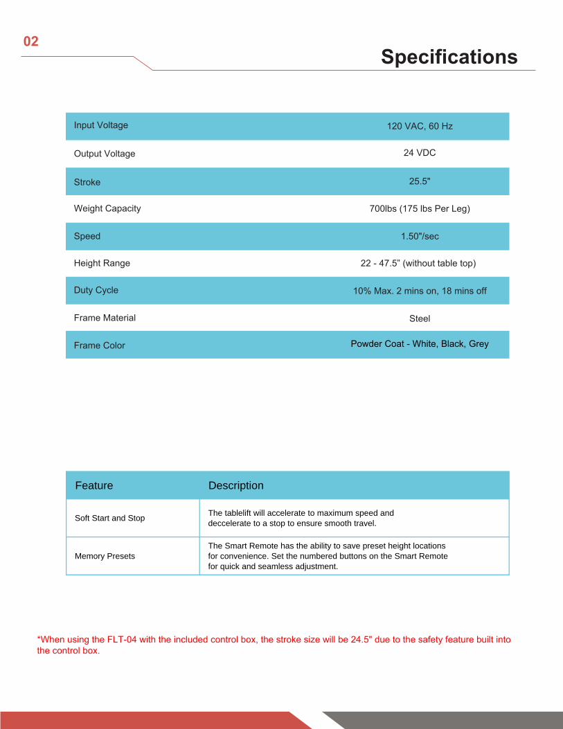
Feature Description
Soft Start and StopThe tablelift will accelerate to maximum speed and
deccelerate to a stop to ensure smooth travel.
Memory Presets
The Smart Remote has the ability to save preset height locations
for convenience. Set the numbered buttons on the Smart Remote
for quick and seamless adjustment.
02Specifications
Duty Cycle 10% Max. 2 mins on, 18 mins off
Height Range 22 - 47.5” (without table top)
Weight Capacity 700lbs (175 lbs Per Leg)
Input Voltage 120 VAC, 60 Hz
Output Voltage 24 VDC
Stroke 25.5"
Speed 1.50"/sec
Frame Material Steel
Powder Coat - White, Black, Grey
*When using the FLT-04 with the included control box, the stroke size will be 24.5" due to the safety feature built intothe control box.
Frame Color

1.9"
1.4"
0.8"
0.6"
2.8" 1.6"
Ø1.8"
Ø0.4"
0.4"
0.2"
1.3"
2.8"
2.4"
0.6"
3.5"
7.1"
6.5"
0.8"
3.4"
6.3"
0.6"
6.4"
5.1"
1.0"
6.1"
7.1"
0.1"
0.1"
Ø0.25"
Ø0.20"
1.9"
0.1"
Legs
Brackets
Stand-Offs
22.0"
3.8"
1.7"
0.5"
6.5"
7.0"
2.0"
3.2"
0.5"
1.0"
M6X10
03Dimensional Drawing

Control Box
Wired RemoteA
C
HS
M1
M2
M3
1.8"
5.8"
0.6"
0.5"
AC
M4
M1 M2 M3 M4HS
10.1"
5.8"
Ø0.2
0.6000
M3
4
2
1˄ ˅
5.7"
3.3"
2.0"
3.4"
2.2"
1.4" 0.2"
04Dimensional Drawing
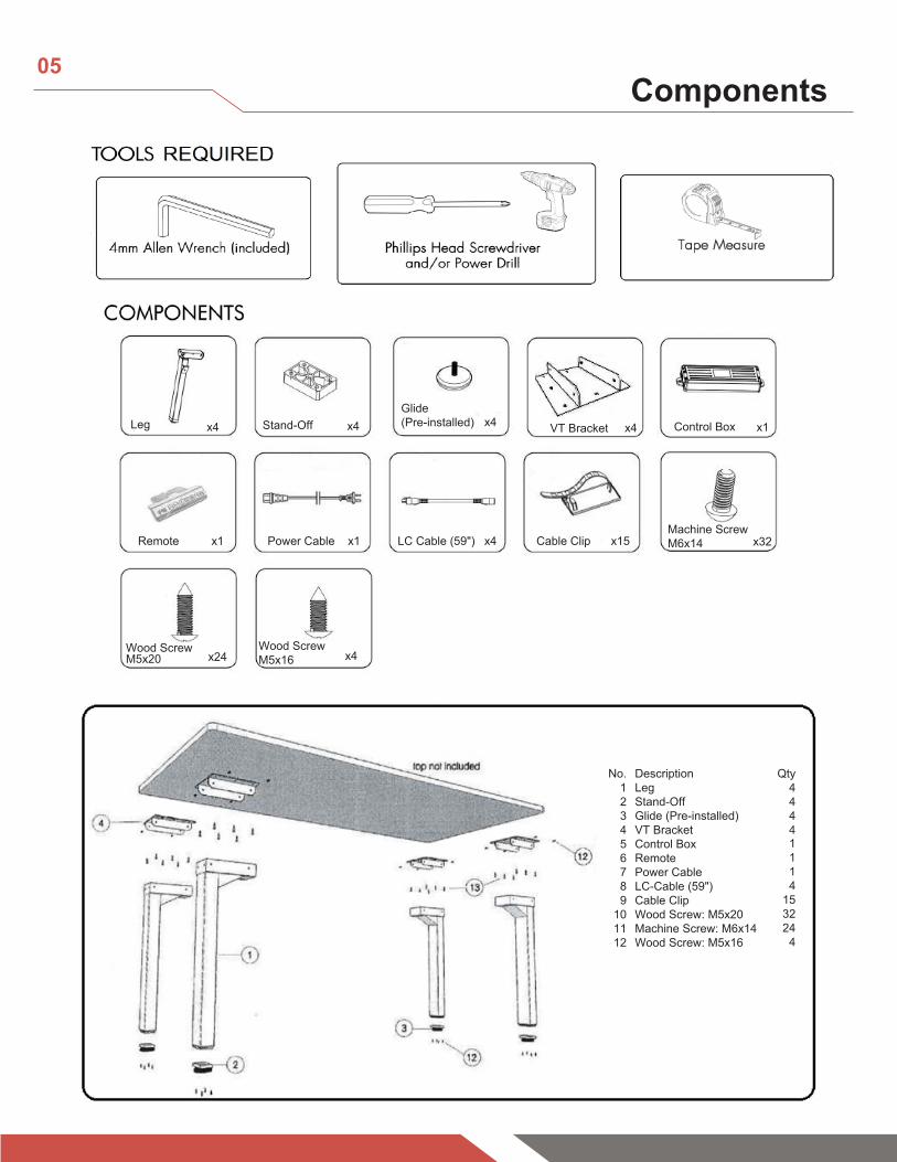
Leg Stand-Off
Wood Screw M5x20
Wood ScrewM5x16
Control Box
Remote Power Cable LC Cable (59") Cable Clip
Glide(Pre-installed)
Machine Screw M6x14
VT Bracketx4 x4
x24 x4
x1 x32
x4
x15
No.123456789
101112
Qty44441114
153224
4
DescriptionLegStand-OffGlide (Pre-installed) VT BracketControl BoxRemotePower CableLC-Cable (59")Cable ClipWood Screw: M5x20 Machine Screw: M6x14 Wood Screw: M5x16
x1
x1 x4
x4
05Components
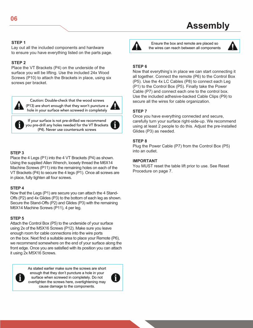
STEP 6Now that everything’s in place we can start connecting it all together. Connect the remote (P6) to the Control Box (P5). Use the 4x LC Cables (P8) to connect each Leg (P1) to the Control Box (P5). Finally take the Power Cable (P7) and connect each one to the control box. Use the included adhesive-backed Cable Clips (P9) to secure all the wires for cable organization.
STEP 7Once you have everything connected and secure, carefully turn your surface right-side-up. We recommend using at least 2 people to do this. Adjust the pre-installed Glides (P3) as needed.
STEP 8Plug the Power Cable (P7) from the Control Box (P5) into an outlet.
IMPORTANTYou MUST reset the table lift prior to use. See Reset Procedure on page 7.
STEP 3Place the 4 Legs (P1) into the 4 VT Brackets (P4) as shown. Using the supplied Allen Wrench, loosely thread the M6X14 Machine Screws (P11) into the remaining holes on each of the VT Brackets (P4) to secure the 4 legs (P1). Once all screws are in place, fully tighten all four screws.
STEP 4Now that the Legs (P1) are secure you can attach the 4 Stand-Offs (P2) and 4x Glides (P3) to the bottom of each leg as shown. Secure the Stand-Offs (P2) and Glides (P3) with the remaining M6X14 Machine Screws (P11), 4 per leg.
STEP 5Attach the Control Box (P5) to the underside of your surface using 2x of the M5X16 Screws (P12). Make sure you leave enough room for cable connections into the wire ports on the box. Next find a suitable area to place your Remote (P6), we recommend somewhere on the end of your surface along the front edge. Once you are satisfied with its position you can attach it using 2x M5X16 Screws.
STEP 1Lay out all the included components and hardware to ensure you have everything listed on the parts page.
STEP 2 Place the VT Brackets (P4) on the underside of the surface you will be lifting. Use the included 24x Wood Screws (P10) to attach the Brackets in place, using six screws per bracket.
Caution: Double-check that the wood screws (P13) are short enough that they won’t puncture a hole in your surface when screwed in completely
If your surface is not pre-drilled we recommend you pre-drill any holes needed for the VT Brackets
(P4). Never use countersunk screws
As stated earlier make sure the screws are short enough that they don’t puncture a hole in your surface when screwed in completely. Do not
overtighten the screws here, overtightening may cause damage to the components.
Ensure the box and remote are placed so the wires can reach between all components
06Assembly

FLT-04
CONTROL BOX
HS
M4
M3
WIRED REMOTE
FLT-04 Leg
[M1,M3]
FLT-04 Leg
[M2,M4]
M2
M1
110VAC
AC
07Setup
M3
4
2
1˄ ˅ M3
4
2
1˄ ˅ M3
4
2
1˄ ˅
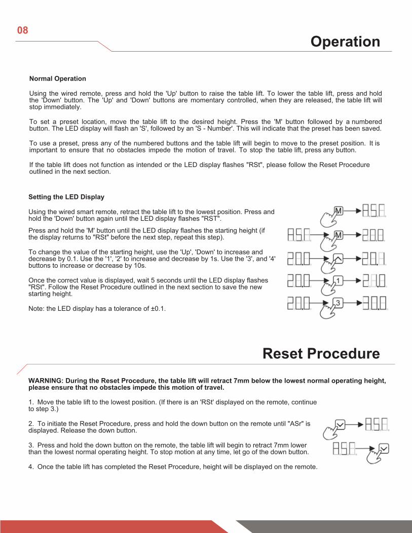
WARNING: During the Reset Procedure, the table lift will retract 7mm below the lowest normal operating height, please ensure that no obstacles impede this motion of travel.
1. Move the table lift to the lowest position. (If there is an 'RSt' displayed on the remote, continueto step 3.)
2. To initiate the Reset Procedure, press and hold the down button on the remote until "ASr" isdisplayed. Release the down button.
3. Press and hold the down button on the remote, the table lift will begin to retract 7mm lowerthan the lowest normal operating height. To stop motion at any time, let go of the down button.
4. Once the table lift has completed the Reset Procedure, height will be displayed on the remote.
08Operation
Using the wired smart remote, retract the table lift to the lowest position. Press and hold the 'Down' button again until the LED display flashes "RST".
Press and hold the 'M' button until the LED display flashes the starting height (if the display returns to "RSt" before the next step, repeat this step).
To change the value of the starting height, use the 'Up', 'Down' to increase and decrease by 0.1. Use the '1', '2' to increase and decrease by 1s. Use the '3', and '4' buttons to increase or decrease by 10s.
Once the correct value is displayed, wait 5 seconds until the LED display flashes "RSt". Follow the Reset Procedure outlined in the next section to save the new starting height.
Note: the LED display has a tolerance of ±0.1.
Normal Operation
Using the wired remote, press and hold the 'Up' button to raise the table lift. To lower the table lift, press and hold the 'Down' button. The 'Up' and 'Down' buttons are momentary controlled, when they are released, the table lift will stop immediately.
To set a preset location, move the table lift to the desired height. Press the 'M' button followed by a numbered button. The LED display will flash an 'S', followed by an 'S - Number'. This will indicate that the preset has been saved.
To use a preset, press any of the numbered buttons and the table lift will begin to move to the preset position. It is important to ensure that no obstacles impede the motion of travel. To stop the table lift, press any button.
If the table lift does not function as intended or the LED display flashes "RSt", please follow the Reset Procedure outlined in the next section.
Setting the LED Display
Reset Procedure

09Troubleshooting
Problem Possible Cause Corrective Action
Low power mode activated Press any button on the remote and LED will activate.
Connection issue Disconnect and reconnect the RJ-45 remote connector. Ensure connection is secure and cable is not damaged.
Limit switch reached Follow "Setting Limit Switches" instructions to remove the programmed limit. If maximum or minimum height limit has been reached, please move the system in the opposite direction.
Connection issue Disconnect and reconnect the Lifting Columns, Control Box, AC Power, and Remote.
Table lift travels at a significantly slower speed than rated
specification.
Weight issue Ensure weight capacity has not exceeded the maximum load rating.
Unusual noise during travel. Weight issue Ensure weight capacity has not exceeded the maximum load rating.
Table lift stops abruptly during travel. Obstacle Ensure there are no obstacles in the path of the table lift. If the movement
continues to fail, initiate the Reset Procedure.
Table lift is not level. Out of sync Disconnect and reconnect all cables (Lifting Column, Control Box, AC Power, and Remote), then initiate the Reset Procedure.
Troubleshooting Guide
Remote LED is off.
Table lift does not move when motion control buttons are
pressed.
Error Code Error Summary Description
E01 M1 overcurrent protection
E02 M2 overcurrent protection
E03 M3 overcurrent protection
E04 M4 overcurrent protection
E07 M1 hall error
E08 M2 hall error
E09 M3 hall error
E10 M4 hall error
H01 Over heat /duty cycle protection
All columns stop moving, remote displays H01 (if LED screen available). Allow the system to rest for 16 minutes, use normally. Follow the Duty Cycle rating to ensure no issues arise from overheating.
Error Codes (remotes with LED display)
All columns stop moving and remote displays E01-E04. Ensure that the total weight capacity of the table lift has not been exceeded and that no obstacles obstruct the movement. Press any key and remote will displayRST, initiate the Reset Procedure. If the issue persists, disconnect and reconnect all of the lifting columns, including the main power. Repeat the Reset Procedure.
All columns stop moving and remote displays E07-E10. Ensure that all columns are still properly connected to the control box. Check to see if any cables have been damaged. Press any key and remote will display RST, initiate the Reset Procedure. If the issue persists, disconnect and reconnect all of the lifting columns, including the main power. Repeat the Reset Procedure.
Have any queries? Our expert engineers are here to help!Progressivedesk.com [email protected]