
FLSTDmSCHE - Refra · Only qualified personnel may install or carry out technical service on the...
92
FLSTDmSCHE Software for the management of chiller screw Code: FLSTDmSCHE User manual High Efficiency Solutions
Transcript of FLSTDmSCHE - Refra · Only qualified personnel may install or carry out technical service on the...

FLSTDmSCHE
Software for the management of chiller screw
Code: FLSTDmSCHE
User manual
H i g h E f f i c i e n c y S o l u t i o n s


IMPORTANT
CAREL bases the development of its products on decades of experience in HVAC/R, on the continuous investments in technological innovations to products, procedures and strict quality processes with in-circuit and functional testing on 100% of its products, and on the most innovative production technology available on the market. CAREL and its subsidiaries nonetheless cannot guarantee that all the aspects of the product and the software included with the product respond to the requirements of the final application, despite the product being developed according to start-of-the-art techniques. The customer (manufacturer, developer or installer of the final equipment) accepts all liability and risk relating to the configuration of the product in order to reach the expected results in relation to the specific final installation and/or equipment. CAREL may, based on specific agreements, acts as a consultant for the positive commissioning of the final unit/application, however in no case does it accept liability for the correct operation of the final equipment/system. The CAREL product is a state-of-the-art product, whose operation is specified in the technical documentation supplied with the product or can be downloaded, even prior to purchase, from the website www.CAREL.com. Each CAREL product, in relation to its advanced level of technology, requires setup/configuration/programming/commissioning to be able to operate in the best possible way for the specific application. The failure to complete such operations, which are required/indicated in the user manual, may cause the final product to malfunction; CAREL accepts no liability in such cases. Only qualified personnel may install or carry out technical service on the product. The customer must only use the product in the manner described in the documentation relating to the product. In addition to observing any further warnings described in this manual, the following warnings must be heeded for all CAREL products:
Prevent the electronic circuits from getting wet. Rain, humidity and all types of liquids or condensate contain corrosive minerals that may damage the electronic circuits. In any case, the product should be used or stored in environments that comply with the temperature and humidity limits specified in the manual.
Do not install the device in particularly hot environments. Too high temperatures may reduce the life of electronic devices, damage them and deform or melt the plastic parts. In any case, the product should be used or stored in environments that comply with the temperature and humidity limits specified in the manual.
Do not attempt to open the device in any way other than described in the manual.
Do not drop, hit or shake the device, as the internal circuits and mechanisms may be irreparably damaged.
Do not use corrosive chemicals, solvents or aggressive detergents to clean the device.
Do not use the product for applications other than those specified in the technical manual. All of the above suggestions likewise apply to the controllers, serial boards, programming keys or any other accessory in the CAREL product portfolio. CAREL adopts a policy of continual development. Consequently, CAREL reserves the right to make changes and improvements to any product described in this document without prior warning. The technical specifications shown in the manual may be changed without prior warning. The liability of CAREL in relation to its products is specified in the CAREL general contract conditions, available on the website www.CAREL.com and/or by specific agreements with customers; specifically, to the extent where allowed by applicable legislation, in no case will CAREL, its employees or subsidiaries be liable for any lost earnings or sales, losses of data and information, costs of replacement goods or services, damage to things or people, downtime or any direct, indirect, incidental, actual, punitive, exemplary, special or consequential damage of any kind whatsoever, whether contractual, extra-contractual or due to negligence, or any other liabilities deriving from the installation, use or impossibility to use the product, even if CAREL or its subsidiaries are warned of the possibility of such damage.
DISPOSAL
INFORMATION FOR USERS ON THE CORRECT HANDLING OF WASTE ELECTRICAL AND ELECTRONIC EQUIPMENT (WEEE) In reference to European Union directive 2002/96/EC issued on 27 January 2003 and the related national legislation, please note that:
WEEE cannot be disposed of as municipal waste and such waste must be collected and disposed of separately;
the public or private waste collection systems defined by local legislation must be used. In addition, the equipment can be returned to the distributor at the end of its working life when buying new equipment;
the equipment may contain hazardous substances: the improper use or incorrect disposal of such may have negative effects on human health and on the environment;
the symbol (crossed-out wheeled bin) shown on the product or on the packaging and on the instruction sheet indicates that the equipment has been introduced onto the market after 13 August 2005 and that it must be disposed of separately;
in the event of illegal disposal of electrical and electronic waste, the penalties are specified by local waste disposal legislation.
Warranty of the materials:2 years (from the date of production, excluding consumables).
Approval:the quality and safety of CAREL INDUSTRIES Hqs products are guaranteed by the ISO 9001 certified design and production system.
WARNING: separate as much as possible the probe and digital input signal cables from the cables carrying inductive loads and power cables to avoid possible electromagnetic disturbance. Never run power cables (including the electrical panel wiring) and signal cables in the same conduits.
The product must be installed with the earthconnected, using the special yellow-green terminal on the terminal block. Do not use the neutral for the earth connection.
ICON LEGEND:
NOTE: to focus attention on topics of great importance; in particular on the practical use of the various operations of the product.
ATTENTION: to bring critical issues to the attention of those using the product.
TUTORIAL: to lead the user along using some simple configuration examples of the most common settings.


INDEX 1. NOTES ...................................................................................................................................................................................................... 6
1.1 FLSTDmSCHE release notes ............................................................................................................................................................... 6 2. INTRODUCTION ....................................................................................................................................................................................... 7
2.1 Main features ........................................................................................................................................................................................ 7 2.2 Field connections .................................................................................................................................................................................. 8 2.3 Components and accessories ............................................................................................................................................................... 9
3. HARDWARE installation .......................................................................................................................................................................... 10 3.1 I/O configuration ................................................................................................................................................................................. 10 3.2 Unit diagrams ..................................................................................................................................................................................... 18 3.3 Probes installation .............................................................................................................................................................................. 19
4. START UP ............................................................................................................................................................................................... 20 4.1 SmartKey ............................................................................................................................................................................................ 20 4.2 pCO Manager ..................................................................................................................................................................................... 20 4.3 USB Pendrive ..................................................................................................................................................................................... 20 4.4 Setting the controller’s address ........................................................................................................................................................... 21 4.5 Setting the address using a terminal ................................................................................................................................................... 21
5. USER INTERFACE .................................................................................................................................................................................. 22 5.1 Terminal pGD1 ................................................................................................................................................................................... 22 5.2 Display................................................................................................................................................................................................ 22 5.3 User Menu .......................................................................................................................................................................................... 22 5.4 MENU DESCRIPTION ........................................................................................................................................................................ 24 5.5 Quick configuration ............................................................................................................................................................................. 24
6. FUNCTIONS ............................................................................................................................................................................................ 25 6.1 Temperature control ........................................................................................................................................................................... 25 6.2 Evaporator pumps .............................................................................................................................................................................. 25 6.3 Antifreeze control ................................................................................................................................................................................ 26 6.4 Compressor rotation ........................................................................................................................................................................... 28 6.5 Pump-Down ........................................................................................................................................................................................ 29 6.6 Compressor management .................................................................................................................................................................. 30 6.7 Eco control and liquid injection ............................................................................................................................................................ 35 6.8 Compressor protections ...................................................................................................................................................................... 35 6.9 Compressor alarm prevention ............................................................................................................................................................. 36 6.10 Compressor alarms management ....................................................................................................................................................... 37 6.11 EVD EVO device ................................................................................................................................................................................ 37 6.12 Condenser pump ................................................................................................................................................................................ 38 6.13 Condenser fans .................................................................................................................................................................................. 38 6.14 Free-Cooling ....................................................................................................................................................................................... 40 6.15 Defrost ................................................................................................................................................................................................ 40 6.16 4-way valve control ............................................................................................................................................................................. 42 6.17 Test functions ..................................................................................................................................................................................... 42
7. PARAMETERS TABLE ............................................................................................................................................................................ 43 7.1 Info ..................................................................................................................................................................................................... 43 7.2 On-Off................................................................................................................................................................................................. 58 7.3 Set ...................................................................................................................................................................................................... 58 7.4 Plant ................................................................................................................................................................................................... 59 7.5 ExV ..................................................................................................................................................................................................... 60 7.6 Source ................................................................................................................................................................................................ 62 7.7 Compressor ........................................................................................................................................................................................ 65 7.8 HW-SW .............................................................................................................................................................................................. 71 7.9 Log-Out .............................................................................................................................................................................................. 71
8. SUPERVISOR TABLE ............................................................................................................................................................................. 72 8.1 Analog variables ................................................................................................................................................................................. 72 8.2 Integer variables ................................................................................................................................................................................. 75 8.3 Digital variables .................................................................................................................................................................................. 81
9. ALARMS .................................................................................................................................................................................................. 88 9.1 Alarms interface .................................................................................................................................................................................. 88 9.2 Alarms table........................................................................................................................................................................................ 88
1. NOTES
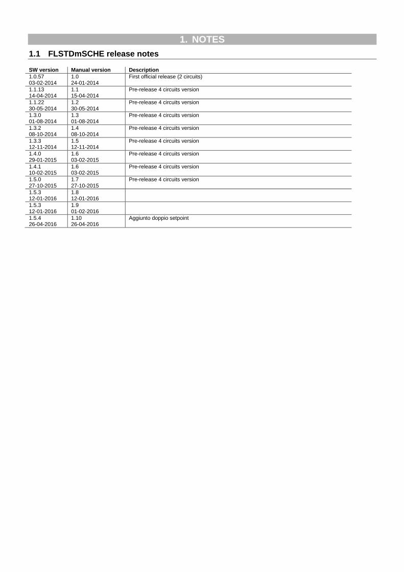
1.1 FLSTDmSCHE release notes SW version Manual version Description
1.0.57 03-02-2014
1.0 24-01-2014
First official release (2 circuits)
1.1.13 14-04-2014
1.1 15-04-2014
Pre-release 4 circuits version
1.1.22 30-05-2014
1.2 30-05-2014
Pre-release 4 circuits version
1.3.0 01-08-2014
1.3 01-08-2014
Pre-release 4 circuits version
1.3.2 08-10-2014
1.4 08-10-2014
Pre-release 4 circuits version
1.3.3 12-11-2014
1.5 12-11-2014
Pre-release 4 circuits version
1.4.0 29-01-2015
1.6 03-02-2015
Pre-release 4 circuits version
1.4.1 10-02-2015
1.6 03-02-2015
Pre-release 4 circuits version
1.5.0 27-10-2015
1.7 27-10-2015
Pre-release 4 circuits version
1.5.3 12-01-2016
1.8 12-01-2016
1.5.3 12-01-2016
1.9 01-02-2016
1.5.4 26-04-2016
1.10 26-04-2016
Aggiunto doppio setpoint

+030221536 FLSTDmSCHE – rel 1.10 – 26/04/2016 7
2. INTRODUCTION
2.1 Main features
FLSTDmSCHE is the CAREL solution for managing chillers and heat pumps with screw compressors.
Usability and display - Easy access to the machine configuration and management parameters with the menu system organised by device (available in the pGD1 terminal). There are three password levels to allow three different access modes to the parameters (read only for assistance, edit for servicing, total access for the manufacturer). The main screen gives quick access to the user functions without a password (information on the status of the machine components, On-Off and machine operating mode, set points) using the UP-DOWN and ENTER keys.
List of functions: Main features Up to four compressors with step, stepless
Up to two compressors with inverter (0-10V or Modbus control(1)
)
Air/Water (A/W) heat pump or chiller
Water/Water (W/W) heat pump or chiller
Free-cooling option
One compressor per circuit
Single evaporator per machine
One separated air condenser per circuit (AW) / Single water circuit per machine (W/W)
Hardware 1 pCO5+ Medium (ExtraLarge also) per unit with one compressor
1 pCO5+ ExtraLarge per unit with two compressors
1 pCO5+ ExtraLarge and, 1 pCO5+ Medium (ExtraLarge also) per unit with three compressors
2 pCO5+ ExtraLarge per unit with four compressors
User interface pGD1
Languages EN-IT-ES-FR-DE
Unit of measure Temperature: International (°C) and Imperial (°F)
Pressure: International (barg) and Imperial (psig)
Settable data format: dd/mm/yy, mm/dd/yy, yy.mm.dd
Control PID on startup
PID during operation
Compressor rotation FIFO
LIFO
Timed
Compressor management Bitzer compressor data preset
Hanbell compressor data preset
RefComp compressor data preset
Frascold compressor data preset
Custom Compressor to set all compressor parameters
ECOnomizer circuit valve option
Liquid injection valve option
EVD EVO driver EVD EVO Management via FB2 with CAREL protocol
One EVD per circuit
Scheduling ON-OFF can be selected for every half hour of the day
Evaporator pump 1-2 pumps
Timed rotation or by pump alarm condition
Water cooled 1-2 pumps
Timed rotation or by pump alarm condition
Air cooled Independent ventilation per circuit or common air circuit
Fan speed modulation on condensing temperature
Fan output On-Off for inverter command or dedicated fan
Optimized startup to short compressor warm-up time
Up to 3 fan output On-Off per circuit (option available with pCO5+ XL only, without Free-cooling, without compressor inverter control)
Defrost Simultaneous
Separate
Independent
Prevention Prevention of compressor working limits for condensing and evaporating temperatures
Evaporator anti-freeze prevention
Alarms Automatic and manual management
Log from application
Log from BIOS
Supervisor protocol Carel
Modbus
LonWorks
Bacnet ready
(1)
The speed setpoint is controlled by modbus, the others safety commands (start, emergency stop, reset alarms) must be connected to che controller pCO5+ by dedicated I/O.
+030221536 FLSTDmSCHE – rel 1.10 – 26/04/2016 8
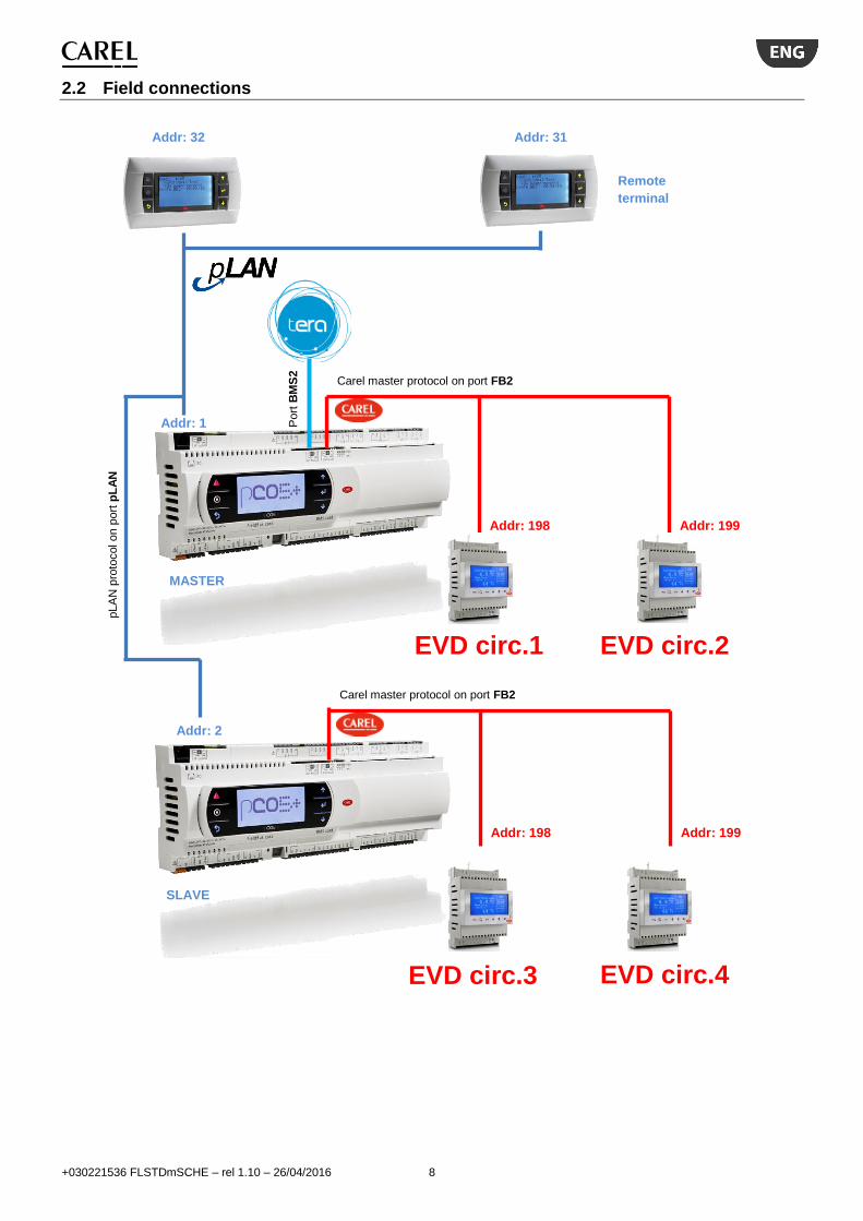
2.2 Field connections
Addr: 32
EVD circ.1 EVD circ.2
Addr: 1
Addr: 198 Addr: 199
Carel master protocol on port FB2
Addr: 31
Remote
terminal
pLA
N p
roto
col on p
ort
pL
AN
Port
BM
S2
EVD circ.3 EVD circ.4
Carel master protocol on port FB2
Addr: 198 Addr: 199
Addr: 2
MASTER
SLAVE

+030221536 FLSTDmSCHE – rel 1.10 – 26/04/2016 9
2.3 Components and accessories FLSTDmSCHE is optimized for pCO5+. The SW can manage up to two screw compressors per board (up to 4 compressors on two boards). Depending on the configuration and type of compressors a different model pCO5+ is necessary.
2.3.1 Table of pCO5+ codes
Unit type pCO5+ code Notes
1 1 screw compressor Step/inverter control
P+500B*A000M0 P+500B*A010M0 P+500B*A050M0
External driver Built-in Carel driver Built-in univ. driver
2 1 screw Bitzer
Step control
P+500B*A100M0 P+500B*A110M0 P+500B*A150M0
External driver Built-in Carel driver Built-in univ. driver
3 1 screw compressor Stepless control
P+500B*A200M0 P+500B*A210M0 P+500B*A250M0
External driver Built-in Carel driver Built-in univ. driver
4 2 screw comps. Step/inverter control
P+500B*A000Z0 External driver only
5 2 screw Bitzer Step control
P+500B*A200Z0 External driver only
6 2 screw comps. Stepless control
P+500B*A400Z0 External driver only
Note: not all codes are active, please check the availability before placing the order.
2.3.2 pGDE terminal (optional) The pGDE graphic display allows the complete management of the user interface through icons and the management of international fonts.
2.3.3 Driver Valve EVD EVO Every circuit must have a singular type EVD EVO valve driver connected. This choice allows for valve driver redundancy. The drivers are both connected to the FieldBus2 (FB2) port, native to the pCO5+ controller. Driver Type EVD EVO Code
EVD EVO single, CAREL valves EVD0000E50
EVD EVO single, Universal EVD0000E20
2.3.4 Temperature sensors Type Range Code
10 kΩ±1%@25 °C, IP67 -50…105/50°C (air/fluid)
NTC*HP*
10 kΩ±1%@25°C (Fast), IP67 -50…105°C (fast) NTC*WF*
50 kΩ±1%@25 °C, IP55 0…150°C NTC*HT*
2.3.5 Pressure sensors
Type Range Code
0-5V HP R134a 0…34,5bar SPKT0033R* SPKT0031S*
0-5V LP R134a -1..9,3bar 1) SPKT0013R*
SPKT0011S*
4-20mA HP R134a 0…30,0bar SPKT0031C*
4-20mA LP R134a -0,5..7,0bar 1)
SPKT0021C*
1) In heat pumps reversible cycle it is preferable to use low pressure sensors with wider range, as follows:
Type Range Code
0-5V LP R134a 0..17,3bar SPKT0043R*
SPKT0041S*
4-20mA LP R134a 0..18,2bar
SPKT0041C*
2.3.6 FB1 connection cards (inverter compressor) The inverters are connected to the FieldBus1 (FB1) port of the pCO5+ controller. The Field Bus card is not native in the controller. FIELD BUS Card Code
Field Bus RS485 Serial Card PCO100FD10
2.3.7 BMS connection cards (optional) The pCO5+ controller has a built in BMS2 port that allows direct interfacing with an RS485 network with maximum baud rate of 19200. Another BMS card can be installed to allow double supervision. The list of cards is below. BMS Card Code
BMS RS485 Card PCOS004850
Ethernet card PCO1000WB0
BCAnet MS/TP 485 card PCO1000BA0
Konnex card PCOS00KXB0
LON PCO10000F0
2.3.8 EVD UltraCap (optional) The Ultracap EVD0000UC0 module is an optional device that completes the EVD EVO product with an external backup module for valve closure in the event of a power failure. The module ensures temporary power to the EVD EVO in the event of a power failure, for enough time to immediately close the electronic valves connected to it. Using the module lets you to avoid the installing of the solenoid valve on the liquid line or the backup battery kit. The module uses backup Ultracap capacitors (EDLC=Electric Double Layer Capacitor) whose charging is managed independently by the module itself. The Ultracap capacitor ensures longer component life compared to a lead battery module. The estimated life of the Ultracap module is 10 years. Also, since it does not use lead batteries, no special precautions are required in terms of safety and pollution.

+030221536 FLSTDmSCHE – rel 1.10 – 26/04/2016 10
3. HARDWARE INSTALLATION
3.1 I/O configuration Analogue inputs
Master Slave Type
U1 Water inlet temperature NTC
U2 Water outlet temperature NTC
U3 External temperature (for Air/Water unit) Condenser water temperature (for Water/Water unit)
NTC
U5 Compressor 1 current Compressor 1 current 0…5V 0/4…20mA
U6 Compressor 2 current Compressor 2 current 0…5V 0/4…20mA
U7 Setpoint compensation
(1)
Setpoint switch (1)
0...1V 0...10V 0/4...20mA 0...5V ON…OFF
(3)
U8 Setpoint compensation
(2)
Setpoint switch (2)
0...1V 0...10V 0/4...20mA 0...5V ON…OFF
(3)
(1)
Available with freecooling disabled or freecooling enabled and master XL board present. (2)
In case of U7 occupied by freecooling valve, U8 is available in case of 2nd
plant pump disabled. (3)
Universal channel used as digital input (ON/OFF) only for double setpoint selection Analogue inputs
Master Analogue inputs
Slave Type
EVD 1 – S1 Compressor 1 evaporating pressure EVD 3 – S1 Compressor 3 evaporating pressure
0-5V 4-20mA 4-20mA remote 4-20mA external
EVD 1 – S2 Compressor 1 suction temperature EVD 3 – S2 Compressor 3 suction temperature
NTC NTC HT NTC SPKP**T0 0-10V
EVD 1 – S3 Compressor 1 condensing pressure EVD 3 – S3 Compressor 3 condensing pressure
0-5V 4-20mA 4-20mA remote 4-20mA external
EVD 1 – S4 Compressor 1 discharge temperature EVD 3 – S4 Compressor 3 discharge temperature NTC NTC HT NTC SPKP**T0
EVD 2 – S1 Compressor 2 evaporating pressure EVD 4 – S1 Compressor 4 evaporating pressure
0-5V 4-20mA 4-20mA remote 4-20mA external
EVD 2 – S2 Compressor 2 suction temperature EVD 4 – S2 Compressor 4 suction temperature
NTC NTC HT NTC SPKP**T0 0-10V
EVD 2 – S3 Compressor 2 condensing pressure EVD 4 – S3 Compressor 4 condensing pressure
0-5V 4-20mA 4-20mA remote 4-20mA external
EVD 2 – S4 Compressor 2 discharge temperature EVD 4 – S4 Compressor 4 discharge temperature NTC NTC HT NTC SPKP**T0
Digital inputs Master Slave
ID1 Remote locking alarm
ID2 Remote Summer/Winter change
ID3 Remote ON-OFF
ID4 Evaporator flow switch
ID5 Condenser flow switch
ID6 Compressor 1 low pressure switch Compressor 3 low pressure switch
ID7 Compressor 1 oil level Compressor 3 oil level
ID8 Fan/condenser pump 1 overload Fan 3 overload
ID9 Compressor 2 low pressure switch Compressor 4 low pressure switch
ID10 Compressor 2 oil level Compressor 4 oil level
ID11 Fan/condenser pump 2 overload Fan 4 overload
ID12 Evaporator pump 1 overload
U4 Evaporator pump 2 overload
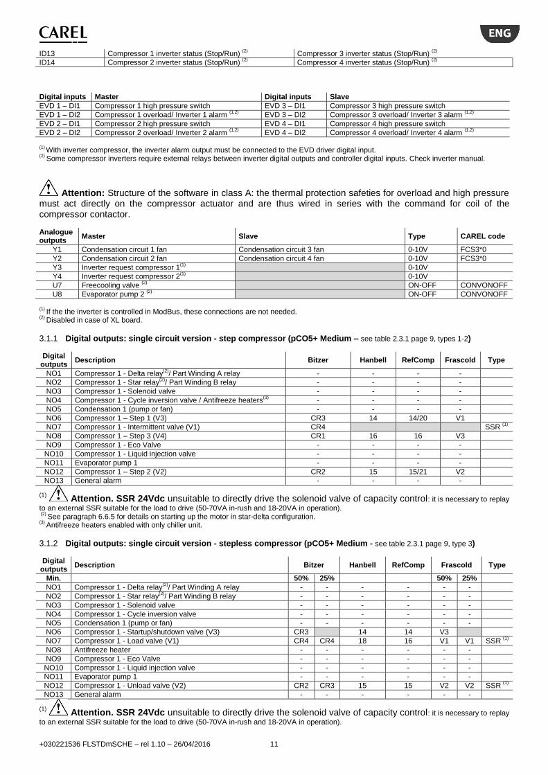
+030221536 FLSTDmSCHE – rel 1.10 – 26/04/2016 11
ID13 Compressor 1 inverter status (Stop/Run) (2)
Compressor 3 inverter status (Stop/Run) (2)
ID14 Compressor 2 inverter status (Stop/Run) (2)
Compressor 4 inverter status (Stop/Run) (2)
Digital inputs Master Digital inputs Slave
EVD 1 – DI1 Compressor 1 high pressure switch EVD 3 – DI1 Compressor 3 high pressure switch
EVD 1 – DI2 Compressor 1 overload/ Inverter 1 alarm (1,2)
EVD 3 – DI2 Compressor 3 overload/ Inverter 3 alarm (1,2)
EVD 2 – DI1 Compressor 2 high pressure switch EVD 4 – DI1 Compressor 4 high pressure switch
EVD 2 – DI2 Compressor 2 overload/ Inverter 2 alarm (1,2)
EVD 4 – DI2 Compressor 4 overload/ Inverter 4 alarm (1,2)
(1)
With inverter compressor, the inverter alarm output must be connected to the EVD driver digital input. (2)
Some compressor inverters require external relays between inverter digital outputs and controller digital inputs. Check inverter manual.
Attention: Structure of the software in class A: the thermal protection safeties for overload and high pressure must act directly on the compressor actuator and are thus wired in series with the command for coil of the compressor contactor. Analogue outputs
Master Slave Type CAREL code
Y1 Condensation circuit 1 fan Condensation circuit 3 fan 0-10V FCS3*0
Y2 Condensation circuit 2 fan Condensation circuit 4 fan 0-10V FCS3*0
Y3 Inverter request compressor 1(1)
0-10V
Y4 Inverter request compressor 2(1)
0-10V
U7 Freecooling valve (2)
ON-OFF CONVONOFF
U8 Evaporator pump 2 (2)
ON-OFF CONVONOFF
(1) If the the inverter is controlled in ModBus, these connections are not needed.
(2) Disabled in case of XL board.
3.1.1 Digital outputs: single circuit version - step compressor (pCO5+ Medium – see table 2.3.1 page 9, types 1-2) Digital
outputs Description Bitzer Hanbell RefComp Frascold Type
NO1 Compressor 1 - Delta relay(2)
/ Part Winding A relay - - - -
NO2 Compressor 1 - Star relay(2)
/ Part Winding B relay - - - -
NO3 Compressor 1 - Solenoid valve - - - -
NO4 Compressor 1 - Cycle inversion valve / Antifreeze heaters(3)
- - - -
NO5 Condensation 1 (pump or fan) - - - -
NO6 Compressor 1 – Step 1 (V3) CR3 14 14/20 V1
NO7 Compressor 1 - Intermittent valve (V1) CR4 SSR (1)
NO8 Compressor 1 – Step 3 (V4) CR1 16 16 V3
NO9 Compressor 1 - Eco Valve - - - -
NO10 Compressor 1 - Liquid injection valve - - - -
NO11 Evaporator pump 1 - - - -
NO12 Compressor 1 – Step 2 (V2) CR2 15 15/21 V2
NO13 General alarm - - - -
(1) Attention. SSR 24Vdc unsuitable to directly drive the solenoid valve of capacity control: it is necessary to replay
to an external SSR suitable for the load to drive (50-70VA in-rush and 18-20VA in operation). (2)
See paragraph 6.6.5 for details on starting up the motor in star-delta configuration. (3)
Antifreeze heaters enabled with only chiller unit.
3.1.2 Digital outputs: single circuit version - stepless compressor (pCO5+ Medium - see table 2.3.1 page 9, type 3) Digital
outputs Description Bitzer Hanbell RefComp Frascold Type
Min. 50% 25% 50% 25%
NO1 Compressor 1 - Delta relay(2)
/ Part Winding A relay - - - - - -
NO2 Compressor 1 - Star relay(2)
/ Part Winding B relay - - - - - -
NO3 Compressor 1 - Solenoid valve - - - - - -
NO4 Compressor 1 - Cycle inversion valve - - - - - -
NO5 Condensation 1 (pump or fan) - - - - - -
NO6 Compressor 1 - Startup/shutdown valve (V3) CR3 14 14 V3
NO7 Compressor 1 - Load valve (V1) CR4 CR4 18 16 V1 V1 SSR (1)
NO8 Antifreeze heater - - - - - -
NO9 Compressor 1 - Eco Valve - - - - - -
NO10 Compressor 1 - Liquid injection valve - - - - - -
NO11 Evaporator pump 1 - - - - - -
NO12 Compressor 1 - Unload valve (V2) CR2 CR3 15 15 V2 V2 SSR (1)
NO13 General alarm - - - - - -
(1) Attention. SSR 24Vdc unsuitable to directly drive the solenoid valve of capacity control: it is necessary to replay
to an external SSR suitable for the load to drive (50-70VA in-rush and 18-20VA in operation).
+030221536 FLSTDmSCHE – rel 1.10 – 26/04/2016 12
(2) See paragraph 6.6.5 for details on starting up the motor in star-delta configuration.
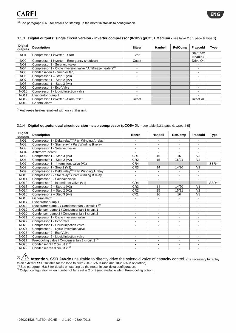
3.1.3 Digital outputs: single circuit version - inverter compressor (0-10V) (pCO5+ Medium - see table 2.3.1 page 9, type 1) Digital
outputs Description Bitzer Hanbell RefComp Frascold Type
NO1 Compressor 1 inverter – Start Start StartCW/Enable1
NO2 Compressor 1 inverter – Emergency shutdown Coast Drive On
NO3 Compressor 1 - Solenoid valve - -
NO4 Compressor 1 - Cycle inversion valve / Antifreeze heaters(1)
- -
NO5 Condensation 1 (pump or fan) - -
NO6 Compressor 1 – Step 1 (V3) - -
NO7 Compressor 1 – Step 2 (V2) - -
NO8 Compressor 1 – Step 3 (V4) - -
NO9 Compressor 1 - Eco Valve - -
NO10 Compressor 1 - Liquid injection valve - -
NO11 Evaporator pump 1 - -
NO12 Compressor 1 inverter –Alarm reset Reset Reset Al.
NO13 General alarm - -
(1) Antifreeze heaters enabled with only chiller unit.
3.1.4 Digital outputs: dual circuit version - step compressor (pCO5+ XL - see table 2.3.1 page 9, types 4-5) Digital
outputs Description Bitzer Hanbell RefComp Frascold Type
NO1 Compressor 1 - Delta relay(2)
/ Part Winding A relay - - - -
NO2 Compressor 1 - Star relay(2)
/ Part Winding B relay - - - -
NO3 Compressor 1 - Solenoid valve - - - -
NO4 Antifreeze heater - - - -
NO5 Compressor 1 – Step 3 (V4) CR1 16 16 V3
NO6 Compressor 1 – Step 2 (V2) CR2 15 15/21 V2
NO7 Compressor 1 – Intermittent valve (V1) CR4 SSR(1)
NO8 Compressor 1 - Step 1 (V3) CR3 14 14/20 V1
NO9 Compressor 2 - Delta relay(2)
/ Part Winding A relay - - - -
NO10 Compressor 2 - Star relay(2)
/ Part Winding B relay - - - -
NO11 Compressor 2 - Solenoid valve - - - -
NO12 Compressor 2 - Intermittent valve (V1) CR4 SSR(1)
NO13 Compressor 2 – Step 1 (V3) CR3 14 14/20 V1
NO14 Compressor 2 – Step 2 (V2) CR2 15 15/21 V2
NO15 Compressor 2 – Step 3 (V4) CR1 16 16 V3
NO16 General alarm - - - -
NO17 Evaporator pump 1 - - - -
NO18 Evaporator pump 2 / Condenser fan 2 circuit 1 (3)
- - - -
NO19 Condenser pump 1 / Condenser fan 1 circuit 1 - - - -
NO20 Condenser pump 2 / Condenser fan 1 circuit 2 - - - -
NO21 Compressor 1 - Cycle inversion valve - - - -
NO22 Compressor 1 - Eco Valve - - - -
NO23 Compressor 1 - Liquid injection valve - - - -
NO24 Compressor 2 - Cycle inversion valve - - - -
NO25 Compressor 2 - Eco Valve - - - -
NO26 Compressor 2 - Liquid injection valve - - - -
NO27 Freecooling valve / Condenser fan 3 circuit 1 (3)
- - - -
NO28 Condenser fan 2 circuit 2 (3)
- - - -
NO29 Condenser fan 3 circuit 2 (3)
- - - -
(1) Attention. SSR 24Vdc unsuitable to directly drive the solenoid valve of capacity control: it is necessary to replay
to an external SSR suitable for the load to drive (50-70VA in-rush and 18-20VA in operation). (2)
See paragraph 6.6.5 for details on starting up the motor in star-delta configuration. (3)
Output configuration when number of fans set is 2 or 3 (not available whith Free-cooling option).

+030221536 FLSTDmSCHE – rel 1.10 – 26/04/2016 13
3.1.5 Digital outputs: dual circuit version - stepless compressor (pCO5+ XL - see table 2.3.1 page 9, type 6) Digital
outputs Description Bitzer Hanbell RefComp Frascold Type
Min. 50% 25% 50% 25%
NO1 Compressor 1 - Delta relay(2)
/ Part Winding A relay - - - - - -
NO2 Compressor 1 - Star relay(2)
/ Part Winding B relay - - - - - -
NO3 Compressor 1 - Solenoid valve - - - - - -
NO4 Antifreeze heater - - - - - -
NO5
NO6 Compressor 1 - Startup/shutdown valve (V3) CR3 14 14 V3
NO7 Compressor 1 - Load valve (V1) CR4 CR4 18 16 V1 V1 SSR (1)
NO8 Compressor 1 - Unload valve (V2) CR2 CR3 15 15 V2 V2 SSR (1)
NO9 Compressor 2 - Delta relay(2)
/ Part Winding A relay - - - - - -
NO10 Compressor 2 - Star relay(2)
/ Part Winding B relay - - - - - -
NO11 Compressor 2 - Solenoid valve - - - - - -
NO12 Compressor 2 - Load valve (V1) CR4 CR4 18 16 V1 V1 SSR (1)
NO13 Compressor 2 - Unload valve (V2) CR2 CR3 15 15 V2 V2 SSR (1)
NO14 Compressor 2 - Startup/shutdown valve (V3) CR3 14 14 V3
NO15
NO16 General alarm - - - - - -
NO17 Evaporator pump 1 - - - - - -
NO18 Evaporator pump 2 / Condenser fan 2 circuit 1 (3)
- - - - - -
NO19 Condenser pump 1 / Condenser fan 1 circuit 1 - - - - - -
NO20 Condenser pump 2 / Condenser fan 1 circuit 2 - - - - - -
NO21 Compressor 1 - Cycle inversion valve - - - - - -
NO22 Compressor 1 - Eco Valve - - - - - -
NO23 Compressor 1 - Liquid injection valve - - - - - -
NO24 Compressor 2 - Cycle inversion valve - - - - - -
NO25 Compressor 2 - Eco Valve - - - - - -
NO26 Compressor 2 - Liquid injection valve - - - - - -
NO27 Freecooling valve / Condenser fan 3 circuit 1 (3)
- - - - - -
NO28 Condenser fan 2 circuit 2 (3)
- - - - - -
NO29 Condenser fan 3 circuit 2 (3)
- - - - - -
(1) Attention. SSR 24Vdc unsuitable to directly drive the solenoid valve of capacity control: it is necessary to replay
to an external SSR suitable for the load to drive (50-70VA in-rush and 18-20VA in operation). (2)
See paragraph 6.6.5 for details on starting up the motor in star-delta configuration. (3)
Output configuration when number of fans set is 2 or 3 (not available whith Free-cooling option).
3.1.6 Digital outputs: dual circuit version - inverter compressor(0-10V) (pCO5+ XL - see table 2.3.1 page 9, type 1) Digital
outputs Description Bitzer Hanbell RefComp Frascold Type
NO1 Compressor 1 inverter – Start Start StartCW/ Enable1
NO2 Compressor 1 inverter – Emergency shutdown Coast Drive On
NO3 Compressor 1 - Solenoid valve - -
NO4 Antifreeze heater - -
NO5 Compressor 1 – Step 3 (V4) - -
NO6 Compressor 1 – Step 2 (V2) - -
NO7 Compressor 1 inverter –Alarm reset Reset Reset Al.
NO8 Compressor 1 - Step 1 (V3) - -
NO9 Compressor 2 inverter – Start Start StartCW/ Enable1
NO10 Compressor 2 inverter – Emergency shutdown Coast Drive On
NO11 Compressor 2 - Solenoid valve - -
NO12 Compressor 2 inverter –Alarm reset Reset Reset Al.
NO13 Compressor 2 – Step 1 (V3) - -
NO14 Compressor 2 – Step 2 (V2) - -
NO15 Compressor 2 – Step 3 (V4) - -
NO16 General alarm - -
NO17 Evaporator pump 1 - -
NO18 Evaporator pump 2
- -
NO19 Condenser pump 1 - -
NO20 Condenser pump 2 - -
NO21 Compressor 1 - Cycle inversion valve - -
NO22 Compressor 1 - Eco Valve - -
NO23 Compressor 1 - Liquid injection valve - -
NO24 Compressor 2 - Cycle inversion valve - -
NO25 Compressor 2 - Eco Valve - -
NO26 Compressor 2 - Liquid injection valve - -
NO27 Freecooling valve - -
NO28
NO29
+030221536 FLSTDmSCHE – rel 1.10 – 26/04/2016 14
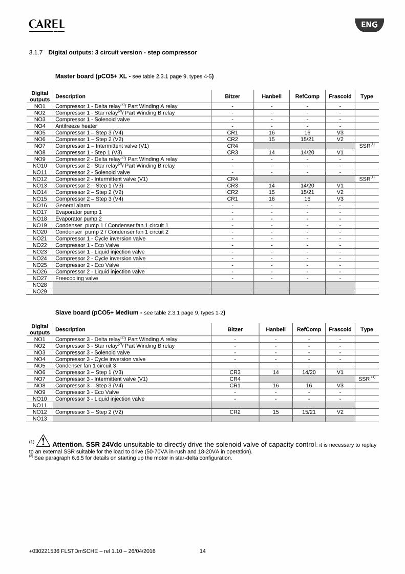
3.1.7 Digital outputs: 3 circuit version - step compressor
Master board (pCO5+ XL - see table 2.3.1 page 9, types 4-5)
Digital
outputs Description Bitzer Hanbell RefComp Frascold Type
NO1 Compressor 1 - Delta relay(2)
/ Part Winding A relay - - - -
NO2 Compressor 1 - Star relay(2)
/ Part Winding B relay - - - -
NO3 Compressor 1 - Solenoid valve - - - -
NO4 Antifreeze heater - - - -
NO5 Compressor 1 – Step 3 (V4) CR1 16 16 V3
NO6 Compressor 1 – Step 2 (V2) CR2 15 15/21 V2
NO7 Compressor 1 – Intermittent valve (V1) CR4 SSR(1)
NO8 Compressor 1 - Step 1 (V3) CR3 14 14/20 V1
NO9 Compressor 2 - Delta relay(2)
/ Part Winding A relay - - - -
NO10 Compressor 2 - Star relay(2)
/ Part Winding B relay - - - -
NO11 Compressor 2 - Solenoid valve - - - -
NO12 Compressor 2 - Intermittent valve (V1) CR4 SSR(1)
NO13 Compressor 2 – Step 1 (V3) CR3 14 14/20 V1
NO14 Compressor 2 – Step 2 (V2) CR2 15 15/21 V2
NO15 Compressor 2 – Step 3 (V4) CR1 16 16 V3
NO16 General alarm - - - -
NO17 Evaporator pump 1 - - - -
NO18 Evaporator pump 2
- - - -
NO19 Condenser pump 1 / Condenser fan 1 circuit 1 - - - -
NO20 Condenser pump 2 / Condenser fan 1 circuit 2 - - - -
NO21 Compressor 1 - Cycle inversion valve - - - -
NO22 Compressor 1 - Eco Valve - - - -
NO23 Compressor 1 - Liquid injection valve - - - -
NO24 Compressor 2 - Cycle inversion valve - - - -
NO25 Compressor 2 - Eco Valve - - - -
NO26 Compressor 2 - Liquid injection valve - - - -
NO27 Freecooling valve - - - -
NO28
NO29
Slave board (pCO5+ Medium - see table 2.3.1 page 9, types 1-2)
Digital outputs
Description Bitzer Hanbell RefComp Frascold Type
NO1 Compressor 3 - Delta relay(2)
/ Part Winding A relay - - - -
NO2 Compressor 3 - Star relay(2)
/ Part Winding B relay - - - -
NO3 Compressor 3 - Solenoid valve - - - -
NO4 Compressor 3 - Cycle inversion valve - - - -
NO5 Condenser fan 1 circuit 3 - - - -
NO6 Compressor 3 – Step 1 (V3) CR3 14 14/20 V1
NO7 Compressor 3 - Intermittent valve (V1) CR4 SSR (1)
NO8 Compressor 3 – Step 3 (V4) CR1 16 16 V3
NO9 Compressor 3 - Eco Valve - - - -
NO10 Compressor 3 - Liquid injection valve - - - -
NO11
NO12 Compressor 3 – Step 2 (V2) CR2 15 15/21 V2
NO13
(1) Attention. SSR 24Vdc unsuitable to directly drive the solenoid valve of capacity control: it is necessary to replay
to an external SSR suitable for the load to drive (50-70VA in-rush and 18-20VA in operation). (2)
See paragraph 6.6.5 for details on starting up the motor in star-delta configuration.

+030221536 FLSTDmSCHE – rel 1.10 – 26/04/2016 15
3.1.8 Digital outputs: 3 circuit version - stepless compressor
Master board (pCO5+ XL - see table 2.3.1 page 9, type 6)
Digital
outputs Description Bitzer Hanbell RefComp Frascold Type
Min. 50% 25% 50% 25%
NO1 Compressor 1 - Delta relay(2)
/ Part Winding A relay - - - - - -
NO2 Compressor 1 - Star relay(2)
/ Part Winding B relay - - - - - -
NO3 Compressor 1 - Solenoid valve - - - - - -
NO4 Antifreeze heater - - - - - -
NO5
NO6 Compressor 1 - Startup/shutdown valve (V3) CR3 14 14 V3
NO7 Compressor 1 - Load valve (V1) CR4 CR4 18 16 V1 V1 SSR (1)
NO8 Compressor 1 - Unload valve (V2) CR2 CR3 15 15 V2 V2 SSR (1)
NO9 Compressor 2 - Delta relay(2)
/ Part Winding A relay - - - - - -
NO10 Compressor 2 - Star relay(2)
/ Part Winding B relay - - - - - -
NO11 Compressor 2 - Solenoid valve - - - - - -
NO12 Compressor 2 - Load valve (V1) CR4 CR4 18 16 V1 V1 SSR (1)
NO13 Compressor 2 - Unload valve (V2) CR2 CR3 15 15 V2 V2 SSR (1)
NO14 Compressor 2 - Startup/shutdown valve (V3) CR3 14 14 V3
NO15
NO16 General alarm - - - - - -
NO17 Evaporator pump 1 - - - - - -
NO18 Evaporator pump 2 - - - - - -
NO19 Condenser pump 1 / Condenser fan 1 circuit 1 - - - - - -
NO20 Condenser pump 2 / Condenser fan 1 circuit 2 - - - - - -
NO21 Compressor 1 - Cycle inversion valve - - - - - -
NO22 Compressor 1 - Eco Valve - - - - - -
NO23 Compressor 1 - Liquid injection valve - - - - - -
NO24 Compressor 2 - Cycle inversion valve - - - - - -
NO25 Compressor 2 - Eco Valve - - - - - -
NO26 Compressor 2 - Liquid injection valve - - - - - -
NO27
NO28
NO29
Slave board (pCO5+ Medium - see table 2.3.1 page 9, type 3) Digital
outputs Description Bitzer Hanbell RefComp Frascold Type
Min. 50% 25% 50% 25%
NO1 Compressor 3 - Delta relay(2)
/ Part Winding A relay - - - - - -
NO2 Compressor 3 - Star relay(2)
/ Part Winding B relay - - - - - -
NO3 Compressor 3 - Solenoid valve - - - - - -
NO4 Compressor 3 - Cycle inversion valve - - - - - -
NO5 Condensation 3 (or fan) - - - - - -
NO6 Compressor 3 - Startup/shutdown valve (V3) CR3 14 14 V3
NO7 Compressor 3 - Load valve (V1) CR4 CR4 18 16 V1 V1 SSR (1)
NO8
NO9 Compressor 3 - Eco Valve - - - - - -
NO10 Compressor 3 - Liquid injection valve - - - - - -
NO11
NO12 Compressor 3 - Unload valve (V2) CR2 CR3 15 15 V2 V2
NO13
(1) Attention. SSR 24Vdc unsuitable to directly drive the solenoid valve of capacity control: it is necessary to replay
to an external SSR suitable for the load to drive (50-70VA in-rush and 18-20VA in operation). (2)
See paragraph 6.6.5 for details on starting up the motor in star-delta configuration.

+030221536 FLSTDmSCHE – rel 1.10 – 26/04/2016 16
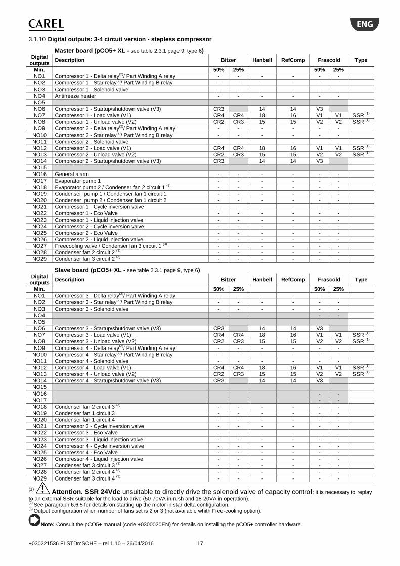
3.1.9 Digital outputs: 3-4 circuit version - step compressor
Master board (pCO5+ XL - see table 2.3.1 page 9, types 4-5) Digital
outputs Description Bitzer Hanbell RefComp Frascold Type
NO1 Compressor 1 - Delta relay(2)
/ Part Winding A relay - - - -
NO2 Compressor 1 - Star relay(2)
/ Part Winding B relay - - - -
NO3 Compressor 1 - Solenoid valve - - - -
NO4 Antifreeze heater - - - -
NO5 Compressor 1 – Step 3 (V4) CR1 16 16 V3
NO6 Compressor 1 – Step 2 (V2) CR2 15 15/21 V2
NO7 Compressor 1 – Intermittent valve (V1) CR4 SSR(1)
NO8 Compressor 1 - Step 1 (V3) CR3 14 14/20 V1
NO9 Compressor 2 - Delta relay(2)
/ Part Winding A relay - - - -
NO10 Compressor 2 - Star relay(2)
/ Part Winding B relay - - - -
NO11 Compressor 2 - Solenoid valve - - - -
NO12 Compressor 2 - Intermittent valve (V1) CR4 SSR(1)
NO13 Compressor 2 – Step 1 (V3) CR3 14 14/20 V1
NO14 Compressor 2 – Step 2 (V2) CR2 15 15/21 V2
NO15 Compressor 2 – Step 3 (V4) CR1 16 16 V3
NO16 General alarm - - - -
NO17 Evaporator pump 1 - - - -
NO18 Evaporator pump 2 / Condenser fan 2 circuit 1 (3)
- - - -
NO19 Condenser pump 1 / Condenser fan 1 circuit 1 - - - -
NO20 Condenser pump 2 / Condenser fan 1 circuit 2 - - - -
NO21 Compressor 1 - Cycle inversion valve - - - -
NO22 Compressor 1 - Eco Valve - - - -
NO23 Compressor 1 - Liquid injection valve - - - -
NO24 Compressor 2 - Cycle inversion valve - - - -
NO25 Compressor 2 - Eco Valve - - - -
NO26 Compressor 2 - Liquid injection valve - - - -
NO27 Freecooling valve / Condenser fan 3 circuit 1 (3)
- - - -
NO28 Condenser fan 2 circuit 2 (3)
- - - -
NO29 Condenser fan 3 circuit 2 (3)
- - - -
Slave board (pCO5+ XL - see table 2.3.1 page 9, types 4-5)
Digital outputs
Description Bitzer Hanbell RefComp Frascold Type
NO1 Compressor 3 - Delta relay(2)
/ Part Winding A relay - - - -
NO2 Compressor 3 - Star relay(2)
/ Part Winding B relay - - - -
NO3 Compressor 3 - Solenoid valve - - - -
NO4
NO5 Compressor 3 – Step 3 (V4) CR1 16 16 V3
NO6 Compressor 3 – Step 2 (V2) CR2 15 15/21 V2
NO7 Compressor 3 – Intermittent valve (V1) CR4 SSR (1)
NO8 Compressor 3 - Step 1 (V3) CR3 14 14/20 V1
NO9 Compressor 4 - Delta relay(2)
/ Part Winding A relay - - - -
NO10 Compressor 4 - Star relay(2)
/ Part Winding B relay - - - -
NO11 Compressor 4 - Solenoid valve - - - -
NO12 Compressor 4 - Intermittent valve (V1) CR4 SSR (1)
NO13 Compressor 4 – Step 1 (V3) CR3 14 14/20 V1
NO14 Compressor 4 – Step 2 (V2) CR2 15 15/21 V2
NO15 Compressor 4 – Step 3 (V4) CR1 16 16 V3
NO16
NO17
NO18 Condenser fan 2 circuit 3 (3)
- - - -
NO19 Condenser fan 1 circuit 3 - - - -
NO20 Condenser fan 1 circuit 4 - - - -
NO21 Compressor 3 - Cycle inversion valve - - - -
NO22 Compressor 3 - Eco Valve - - - -
NO23 Compressor 3 - Liquid injection valve - - - -
NO24 Compressor 4 - Cycle inversion valve - - - -
NO25 Compressor 4 - Eco Valve - - - -
NO26 Compressor 4 - Liquid injection valve - - - -
NO27 Condenser fan 3 circuit 3 (3)
- - - -
NO28 Condenser fan 2 circuit 4 (3)
- - - -
NO29 Condenser fan 3 circuit 4 (3)
- - - -
(1) Attention. SSR 24Vdc unsuitable to directly drive the solenoid valve of capacity control: it is necessary to replay
to an external SSR suitable for the load to drive (50-70VA in-rush and 18-20VA in operation). (2)
See paragraph 6.6.5 for details on starting up the motor in star-delta configuration. (3)
Output configuration when number of fans set is 2 or 3 (not available whith Free-cooling option).
+030221536 FLSTDmSCHE – rel 1.10 – 26/04/2016 17
3.1.10 Digital outputs: 3-4 circuit version - stepless compressor
Master board (pCO5+ XL - see table 2.3.1 page 9, type 6) Digital
outputs Description Bitzer Hanbell RefComp Frascold Type
Min. 50% 25% 50% 25%
NO1 Compressor 1 - Delta relay(2)
/ Part Winding A relay - - - - - -
NO2 Compressor 1 - Star relay(2)
/ Part Winding B relay - - - - - -
NO3 Compressor 1 - Solenoid valve - - - - - -
NO4 Antifreeze heater - - - - - -
NO5
NO6 Compressor 1 - Startup/shutdown valve (V3) CR3 14 14 V3
NO7 Compressor 1 - Load valve (V1) CR4 CR4 18 16 V1 V1 SSR (1)
NO8 Compressor 1 - Unload valve (V2) CR2 CR3 15 15 V2 V2 SSR (1)
NO9 Compressor 2 - Delta relay(2)
/ Part Winding A relay - - - - - -
NO10 Compressor 2 - Star relay(2)
/ Part Winding B relay - - - - - -
NO11 Compressor 2 - Solenoid valve - - - - - -
NO12 Compressor 2 - Load valve (V1) CR4 CR4 18 16 V1 V1 SSR (1)
NO13 Compressor 2 - Unload valve (V2) CR2 CR3 15 15 V2 V2 SSR (1)
NO14 Compressor 2 - Startup/shutdown valve (V3) CR3 14 14 V3
NO15
NO16 General alarm - - - - - -
NO17 Evaporator pump 1 - - - - - -
NO18 Evaporator pump 2 / Condenser fan 2 circuit 1 (3)
- - - - - -
NO19 Condenser pump 1 / Condenser fan 1 circuit 1 - - - - - -
NO20 Condenser pump 2 / Condenser fan 1 circuit 2 - - - - - -
NO21 Compressor 1 - Cycle inversion valve - - - - - -
NO22 Compressor 1 - Eco Valve - - - - - -
NO23 Compressor 1 - Liquid injection valve - - - - - -
NO24 Compressor 2 - Cycle inversion valve - - - - - -
NO25 Compressor 2 - Eco Valve - - - - - -
NO26 Compressor 2 - Liquid injection valve - - - - - -
NO27 Freecooling valve / Condenser fan 3 circuit 1 (3)
- - - - - -
NO28 Condenser fan 2 circuit 2 (3)
- - - - - -
NO29 Condenser fan 3 circuit 2 (3)
- - - - - -
Slave board (pCO5+ XL - see table 2.3.1 page 9, type 6) Digital
outputs Description Bitzer Hanbell RefComp Frascold Type
Min. 50% 25% 50% 25%
NO1 Compressor 3 - Delta relay(2)
/ Part Winding A relay - - - - - -
NO2 Compressor 3 - Star relay(2)
/ Part Winding B relay - - - - - -
NO3 Compressor 3 - Solenoid valve - - - - - -
NO4 - -
NO5
NO6 Compressor 3 - Startup/shutdown valve (V3) CR3 14 14 V3
NO7 Compressor 3 - Load valve (V1) CR4 CR4 18 16 V1 V1 SSR (1)
NO8 Compressor 3 - Unload valve (V2) CR2 CR3 15 15 V2 V2 SSR (1)
NO9 Compressor 4 - Delta relay(2)
/ Part Winding A relay - - - - - -
NO10 Compressor 4 - Star relay(2)
/ Part Winding B relay - - - - - -
NO11 Compressor 4 - Solenoid valve - - - - - -
NO12 Compressor 4 - Load valve (V1) CR4 CR4 18 16 V1 V1 SSR (1)
NO13 Compressor 4 - Unload valve (V2) CR2 CR3 15 15 V2 V2 SSR (1)
NO14 Compressor 4 - Startup/shutdown valve (V3) CR3 14 14 V3
NO15
NO16 - -
NO17 - -
NO18 Condenser fan 2 circuit 3 (3)
- - - - - -
NO19 Condenser fan 1 circuit 3 - - - - - -
NO20 Condenser fan 1 circuit 4 - - - - - -
NO21 Compressor 3 - Cycle inversion valve - - - - - -
NO22 Compressor 3 - Eco Valve - - - - - -
NO23 Compressor 3 - Liquid injection valve - - - - - -
NO24 Compressor 4 - Cycle inversion valve - - - - - -
NO25 Compressor 4 - Eco Valve - - - - - -
NO26 Compressor 4 - Liquid injection valve - - - - - -
NO27 Condenser fan 3 circuit 3 (3)
- - - - - -
NO28 Condenser fan 2 circuit 4 (3)
- - - - - -
NO29 Condenser fan 3 circuit 4 (3)
- - - - - -
(1) Attention. SSR 24Vdc unsuitable to directly drive the solenoid valve of capacity control: it is necessary to replay
to an external SSR suitable for the load to drive (50-70VA in-rush and 18-20VA in operation). (2)
See paragraph 6.6.5 for details on starting up the motor in star-delta configuration. (3)
Output configuration when number of fans set is 2 or 3 (not available whith Free-cooling option).
Note: Consult the pCO5+ manual (code +0300020EN) for details on installing the pCO5+ controller hardware.

+030221536 FLSTDmSCHE – rel 1.10 – 26/04/2016 18
3.2 Unit diagrams Below are some details on the installation position for the probes referred to the first circuit. We recommend installing them in the position described.
Analogue inputs Digital inputs
U1 Water inlet temperature ID4 Evaporator flow switch
U2 Water outlet temperature ID6 Circuit 1 LP switch
U3 Outdoor temperature ID8 Condenser 1 overload
S1 Suction pressure ID12 Evaporator 1 overload
S2 Suction temperature ID5 Condenser flow switch
S3 Discharge pressure EVD DI1 Circuit 1 HP switch
S4 Discharge temperature EVD DI2 Compressor 1 overload
Devices
CMP Compressor
EVP Evaporator
COND Condenser
ExV Expansion valve
SOL Liquid solenoid valve
PMP Pump
Compressor probe detail Evaporator pump detail
Air cooled detail Water cooled detail
Gas side reversability detail Water side reversability detail on water/water unit
M
EVAP CMP
SOL ExV
COND
P P T P P
T
S1 S2 ID6
DI2
S3 DI1
S4
F
U1
T
T
U2 ID4
ID12
PMP
T
ID8
U3
T
PMP
F
U3
ID8
ID5
P P T P P T
S1 S2 ID6 S3 S4 DI1
U2 T
PLANT
EXTERNAL SOURCE
T
T
U1
U3 F
F
ID5
ID4
+030221536 FLSTDmSCHE – rel 1.10 – 26/04/2016 19
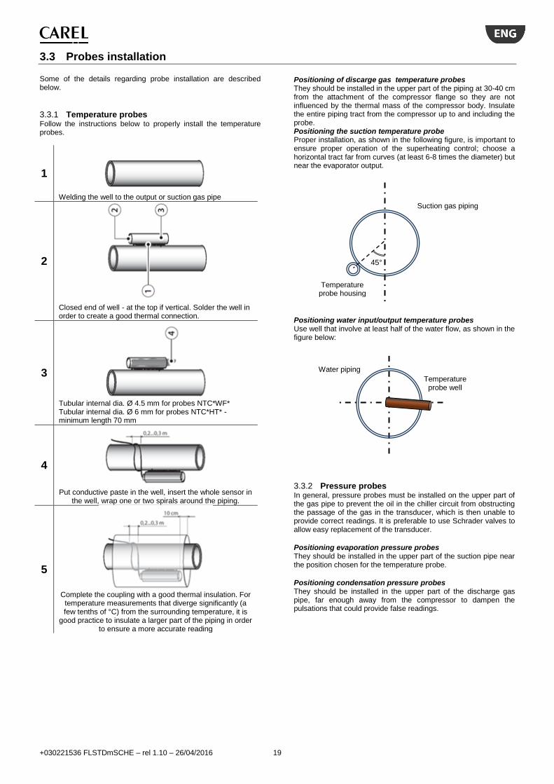
3.3 Probes installation Some of the details regarding probe installation are described below.
3.3.1 Temperature probes Follow the instructions below to properly install the temperature probes.
1
Welding the well to the output or suction gas pipe
2
Closed end of well - at the top if vertical. Solder the well in order to create a good thermal connection.
3
Tubular internal dia. Ø 4.5 mm for probes NTC*WF* Tubular internal dia. Ø 6 mm for probes NTC*HT* - minimum length 70 mm
4
Put conductive paste in the well, insert the whole sensor in
the well, wrap one or two spirals around the piping.
5
Complete the coupling with a good thermal insulation. For
temperature measurements that diverge significantly (a few tenths of °C) from the surrounding temperature, it is
good practice to insulate a larger part of the piping in order to ensure a more accurate reading
Positioning of discarge gas temperature probes They should be installed in the upper part of the piping at 30-40 cm from the attachment of the compressor flange so they are not influenced by the thermal mass of the compressor body. Insulate the entire piping tract from the compressor up to and including the probe. Positioning the suction temperature probe Proper installation, as shown in the following figure, is important to ensure proper operation of the superheating control; choose a horizontal tract far from curves (at least 6-8 times the diameter) but near the evaporator output.
Positioning water input/output temperature probes Use well that involve at least half of the water flow, as shown in the figure below:
3.3.2 Pressure probes In general, pressure probes must be installed on the upper part of the gas pipe to prevent the oil in the chiller circuit from obstructing the passage of the gas in the transducer, which is then unable to provide correct readings. It is preferable to use Schrader valves to allow easy replacement of the transducer.
Positioning evaporation pressure probes They should be installed in the upper part of the suction pipe near the position chosen for the temperature probe.
Positioning condensation pressure probes They should be installed in the upper part of the discharge gas pipe, far enough away from the compressor to dampen the pulsations that could provide false readings.
Water piping
Temperature probe well
45°
Suction gas piping
Temperature probe housing
+030221536 FLSTDmSCHE – rel 1.10 – 26/04/2016 20
4. START UP The following methods can be used to update the firmware and acquire the log files on pCO controllers:
Smart Key programming key;
pCO Manager, a program to install on the PC;
an USB pendrive.
4.1 SmartKey The PCOS00AKY0 key is an electronic device used to program and service pCO Sistema controllers. The PCOS00AKY0 key simplifi es data transfer between the controllers installed and a personal computer by exploiting the high capacity fl ash memory for storing software applications, BIOS and variable logs. The pCO is connected directly via the telephone connector using the cable supplied, while to transfer data to a personal computer the PCOS00AKC0 USB adapter is required. The device is powered either by the USB port on the PC or by the controller, therefore no external power supply is necessary.
Note:for operating steps see the pCO5+ manual cod. +0300020EN par. 9.1.
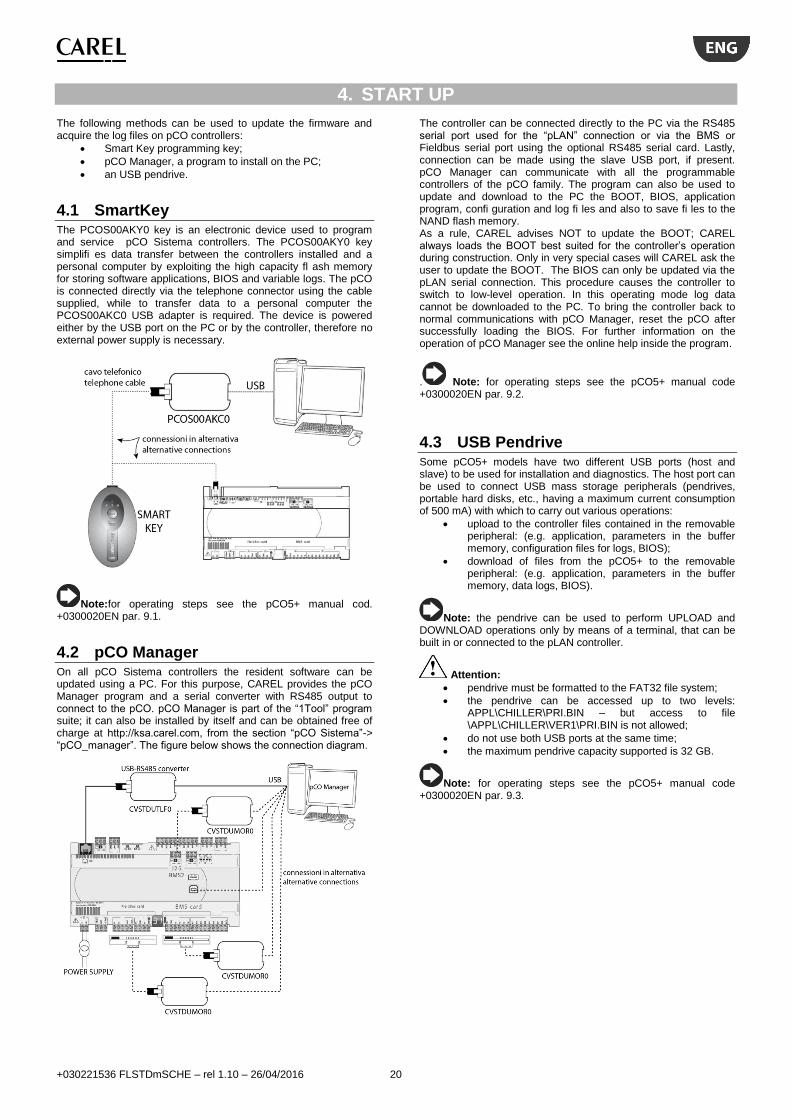
4.2 pCO Manager On all pCO Sistema controllers the resident software can be updated using a PC. For this purpose, CAREL provides the pCO Manager program and a serial converter with RS485 output to connect to the pCO. pCO Manager is part of the “1Tool” program suite; it can also be installed by itself and can be obtained free of charge at http://ksa.carel.com, from the section “pCO Sistema”-> “pCO_manager”. The figure below shows the connection diagram.
The controller can be connected directly to the PC via the RS485 serial port used for the “pLAN” connection or via the BMS or Fieldbus serial port using the optional RS485 serial card. Lastly, connection can be made using the slave USB port, if present. pCO Manager can communicate with all the programmable controllers of the pCO family. The program can also be used to update and download to the PC the BOOT, BIOS, application program, confi guration and log fi les and also to save fi les to the NAND flash memory. As a rule, CAREL advises NOT to update the BOOT; CAREL always loads the BOOT best suited for the controller’s operation during construction. Only in very special cases will CAREL ask the user to update the BOOT. The BIOS can only be updated via the pLAN serial connection. This procedure causes the controller to switch to low-level operation. In this operating mode log data cannot be downloaded to the PC. To bring the controller back to normal communications with pCO Manager, reset the pCO after successfully loading the BIOS. For further information on the operation of pCO Manager see the online help inside the program.
. Note: for operating steps see the pCO5+ manual code +0300020EN par. 9.2.
4.3 USB Pendrive Some pCO5+ models have two different USB ports (host and slave) to be used for installation and diagnostics. The host port can be used to connect USB mass storage peripherals (pendrives, portable hard disks, etc., having a maximum current consumption of 500 mA) with which to carry out various operations:
upload to the controller files contained in the removable peripheral: (e.g. application, parameters in the buffer memory, configuration files for logs, BIOS);
download of files from the pCO5+ to the removable peripheral: (e.g. application, parameters in the buffer memory, data logs, BIOS).
Note: the pendrive can be used to perform UPLOAD and DOWNLOAD operations only by means of a terminal, that can be built in or connected to the pLAN controller.
Attention:
pendrive must be formatted to the FAT32 file system;
the pendrive can be accessed up to two levels: APPL\CHILLER\PRI.BIN – but access to file \APPL\CHILLER\VER1\PRI.BIN is not allowed;
do not use both USB ports at the same time;
the maximum pendrive capacity supported is 32 GB.
Note: for operating steps see the pCO5+ manual code +0300020EN par. 9.3.
+030221536 FLSTDmSCHE – rel 1.10 – 26/04/2016 21
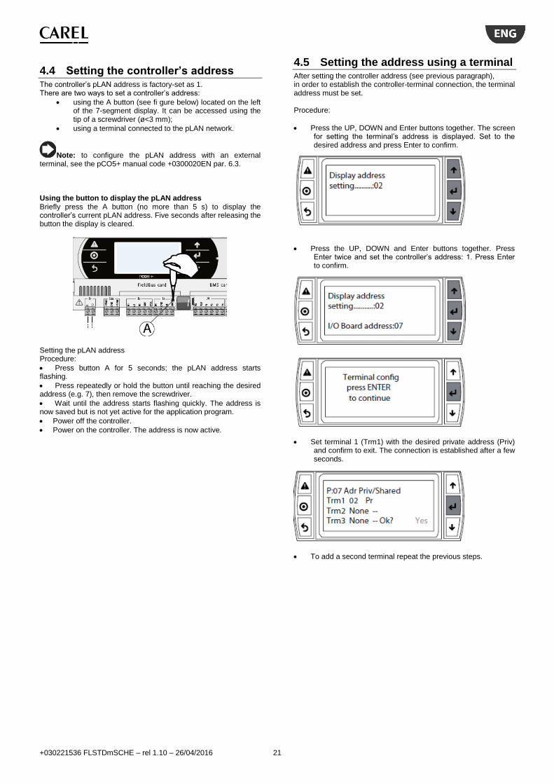
4.4 Setting the controller’s address The controller’s pLAN address is factory-set as 1. There are two ways to set a controller’s address:
using the A button (see fi gure below) located on the left of the 7-segment display. It can be accessed using the tip of a screwdriver (ø<3 mm);
using a terminal connected to the pLAN network.
Note: to configure the pLAN address with an external terminal, see the pCO5+ manual code +0300020EN par. 6.3. Using the button to display the pLAN address Briefly press the A button (no more than 5 s) to display the controller’s current pLAN address. Five seconds after releasing the button the display is cleared.
Setting the pLAN address Procedure:
Press button A for 5 seconds; the pLAN address starts flashing.
Press repeatedly or hold the button until reaching the desired address (e.g. 7), then remove the screwdriver.
Wait until the address starts flashing quickly. The address is now saved but is not yet active for the application program.
Power off the controller.
Power on the controller. The address is now active.
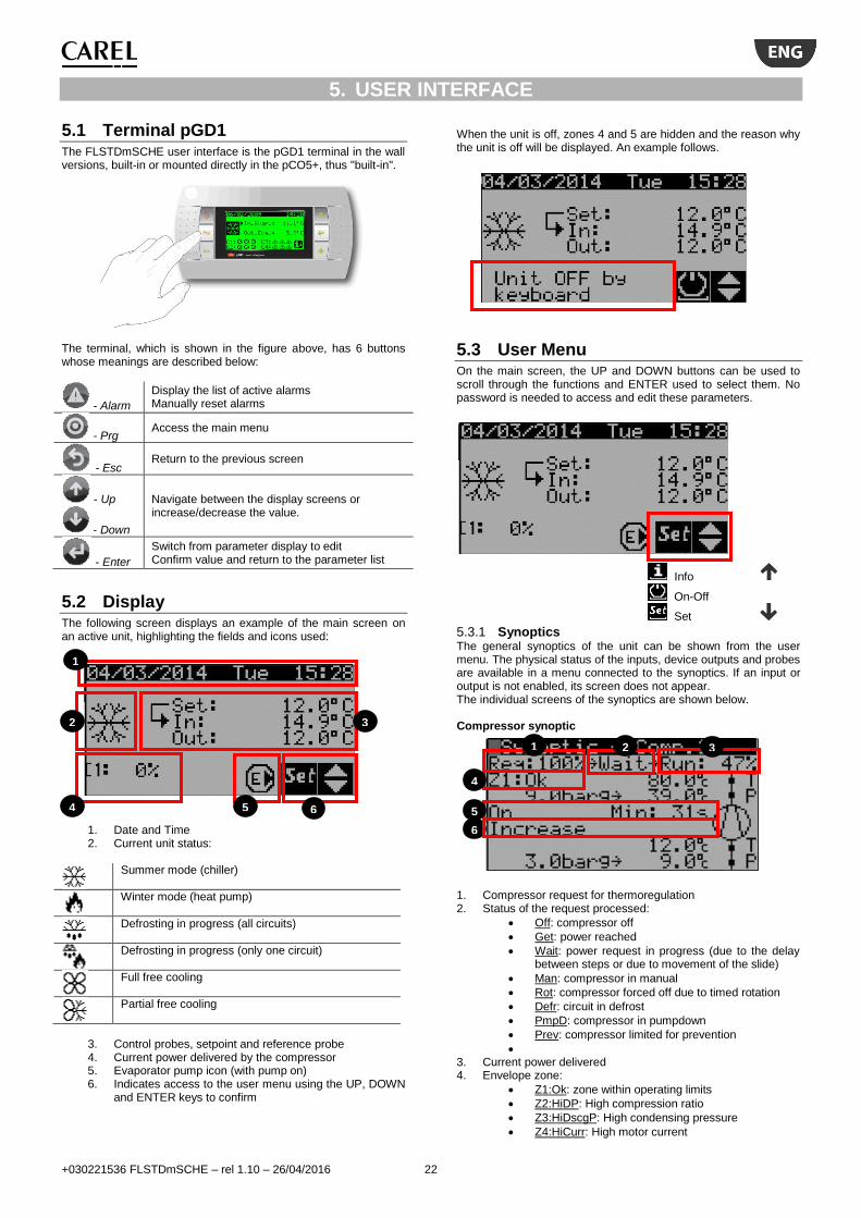
4.5 Setting the address using a terminal After setting the controller address (see previous paragraph), in order to establish the controller-terminal connection, the terminal address must be set. Procedure:
Press the UP, DOWN and Enter buttons together. The screen for setting the terminal’s address is displayed. Set to the desired address and press Enter to confirm.
Press the UP, DOWN and Enter buttons together. Press Enter twice and set the controller’s address: 1. Press Enter to confirm.
Set terminal 1 (Trm1) with the desired private address (Priv) and confirm to exit. The connection is established after a few seconds.
To add a second terminal repeat the previous steps.
+030221536 FLSTDmSCHE – rel 1.10 – 26/04/2016 22
5. USER INTERFACE
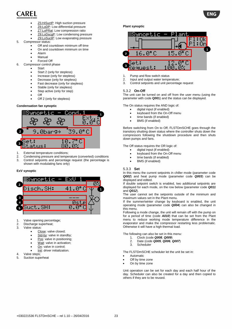
5.1 Terminal pGD1 The FLSTDmSCHE user interface is the pGD1 terminal in the wall versions, built-in or mounted directly in the pCO5+, thus "built-in".
The terminal, which is shown in the figure above, has 6 buttons whose meanings are described below:
- Alarm
Display the list of active alarms Manually reset alarms
- Prg Access the main menu
- Esc Return to the previous screen
- Up
- Down
Navigate between the display screens or increase/decrease the value.
- Enter
Switch from parameter display to edit Confirm value and return to the parameter list
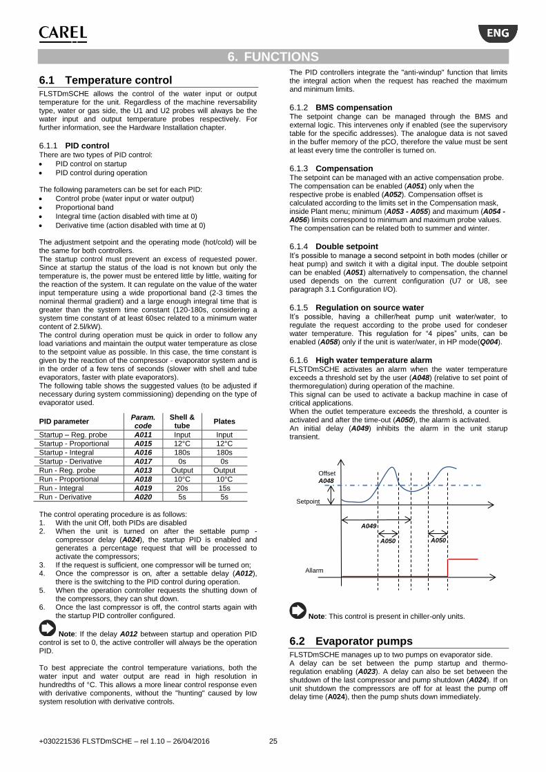
5.2 Display The following screen displays an example of the main screen on an active unit, highlighting the fields and icons used:
1. Date and Time 2. Current unit status:
Summer mode (chiller)
Winter mode (heat pump)
Defrosting in progress (all circuits)
Defrosting in progress (only one circuit)
Full free cooling
Partial free cooling
3. Control probes, setpoint and reference probe 4. Current power delivered by the compressor 5. Evaporator pump icon (with pump on) 6. Indicates access to the user menu using the UP, DOWN
and ENTER keys to confirm
When the unit is off, zones 4 and 5 are hidden and the reason why the unit is off will be displayed. An example follows.
5.3 User Menu On the main screen, the UP and DOWN buttons can be used to scroll through the functions and ENTER used to select them. No password is needed to access and edit these parameters.
Info
On-Off
Set
5.3.1 Synoptics The general synoptics of the unit can be shown from the user menu. The physical status of the inputs, device outputs and probes are available in a menu connected to the synoptics. If an input or output is not enabled, its screen does not appear. The individual screens of the synoptics are shown below. Compressor synoptic
1. Compressor request for thermoregulation 2. Status of the request processed:
Off: compressor off
Get: power reached
Wait: power request in progress (due to the delay between steps or due to movement of the slide)
Man: compressor in manual
Rot: compressor forced off due to timed rotation
Defr: circuit in defrost
PmpD: compressor in pumpdown
Prev: compressor limited for prevention
3. Current power delivered 4. Envelope zone:
Z1:Ok: zone within operating limits
Z2:HiDP: High compression ratio
Z3:HiDscgP: High condensing pressure
Z4:HiCurr: High motor current
1
2 3
4 5 6
1 2 3
4
5
6
+030221536 FLSTDmSCHE – rel 1.10 – 26/04/2016 23
Z5:HiSuctP: High suction pressure
Z6:LoDP: Low differential pressure
Z7:LoPRat: Low compression ratio
Z8:LoDscgP: Low condensing pressure
Z9:LoSuctP: Low evaporating pressure 5. Compressor status:
Off and countdown minimum off time
On and countdown minimum on time
Alarm
Manual
Forced Off 6. Compressor control phase
Start
Start 2 (only for stepless)
Increase (only for stepless)
Decrease (only for stepless)
Fast decrease (only for stepless)
Stable (only for stepless)
Step active (only for step)
Off
Off 2 (only for stepless) Condensation fan synoptic
1. External temperature conditions; 2. Condensing pressure and temperature (converted) conditions 3. Control setpoints and percentage request (the percentage is
shown with modulating fans only) ExV synoptic
1. Valve opening percentage; 2. Discharge superheat; 3. Valve status:
Close: valve closed;
Std-by: valve in standby;
Pos: valve in positioning;
Wait: valve in activation;
On: valve in control;
Init: driver initialization. 4. Valve steps; 5. Suction superheat
Plant synoptic
1. Pump and flow switch status 2. Input and output water temperature; 3. Control setpoints and unit percentage request
5.3.2 On-Off The unit can be turned on and off from the user menu (using the parameter with code Q001) and the status can be displayed. The On status requires the AND logic of:
digital input (if enabled)
keyboard from the On-Off menu
time bands (if enabled)
BMS (if enabled) Before switching from On to Off, FLSTDmSCHE goes through the transitory shutting down status where the controller shuts down the compressors following the shutdown procedure and then shuts down pumps and fans. The Off status requires the OR logic of:
digital input (if enabled)
keyboard from the On-Off menu
time bands (if enabled)
BMS (if enabled)
5.3.3 Set In this menu the current setpoints in chiller mode (parameter code Q002) and heat pump mode (parameter code Q003) can be displayed and edited. If double setpoint switch is enabled, two additional setpoints are displayed for each mode, on the row below (parameter code Q011 and Q012). The user cannot set the setpoints outside of the minimum and maximum values set in the Plant menu. If the summer/winter change by keyboard is enabled, the unit operating mode (parameter code Q004) can also be changed in this menu. Following a mode change, the unit will remain off with the pump on for a period of time (code A010) that can be set from the Plant menu to reduce working mode temperature difference in the evaporator and make the compressor restarting less problematic. Otherwise it will have a high thermal load. The following can also be set in this menu:
1. Clock (code Q008, Q009) 2. Date (code Q005, Q006, Q007) 3. Scheduler
The FLSTDmSCHE scheduler let the unit be set in:
Automatic
Off by time zone
On by time zone
Unit operation can be set for each day and each half hour of the day. Scheduler can also be created for a day and then copied to others if they are to be reused.
1
2
3
1
2
3
4
5
1
2
3

+030221536 FLSTDmSCHE – rel 1.10 – 26/04/2016 24
5.4 MENU DESCRIPTION Regardless of the displayed screen, pressing the programming key accesses the password entry screen which allows access to the main menu shown below.
5.4.1 Password Management The program has 3 different password levels: 1. Advanced user (maintenance): read only access to all
parameters. Default password: 1234. 2. Service: read access to all parameters with the ability to edit
some of them (for more information on the parameters that can be changed, see the parameters table). Default password: 1234.
3. Manufacturer: read/write access to all parameters. Default password: 1234.
As soon as the password is entered in the menu screen, the type of password can be seen, as shown in the following screen:
In the parameters screen, the access needed to edit the parameters is shown, always with the same codes. An example follows.
Once the password is entered it will be maintained for 5 minutes from the last time a key was pressed and then the password will need to be re-entered in order to access the parameters of the advanced functions. In the Log-Out menu, the password can be force entered without waiting 5 minutes.
5.4.2 Parameters code FLSTDmSCHE has a code for each individual parameter to clearly identify them. Only the parameters are coded and thus the values that can be accessed in read/write mode that characterise how the unit operates. The read only values are not coded. Each parameter has a 4 digit code identified as follows:
1st digit 2nd digit 3rd 4th
Main menu code
Secondary menu code
Parameter code
5.5 Quick configuration For quick plant configuration, proceed as follows. Menu A. Plant Plant has all of the parameters for the evaporator and thus the unit load.
1. Heat pump present (parameter code A042) 2. Pump number (parameter code A043)
Menu B. ExV ExV has all of the parameters for the electronic expansion valve and the solenoid valve.
1. ExV Type (parameter code B043) 2. ExV control (parameter code B044) 3. Pump-down configuration (parameter code B037)
Menu C Condenser Condenser has all of the parameters for the unit condensation.
1. AW or WW unit type (parameter code C047) 2. Pump number with WW unit (parameter code C045)
Menu Da. Config. compressor Config. compressor has all of the compressor parameters.
1. Compressor manufacturer (parameter code Da83) 2. Compressor model (parameter code Da84) 3. Number of compressors (parameter code Da77) 4. Refrigerant (parameter code Da78) 5. Probe configuration 6. Compressor ignition type (parameter code Da42)
Menu E. HW/SW HW/SW has all of the parameters for the pCO5+ configuration and the specific SW functions that are not related to unit management. Menu F. Log-Out Log-Out can be used to exit the set password or change the access password.
+030221536 FLSTDmSCHE – rel 1.10 – 26/04/2016 25
6. FUNCTIONS
6.1 Temperature control FLSTDmSCHE allows the control of the water input or output temperature for the unit. Regardless of the machine reversability type, water or gas side, the U1 and U2 probes will always be the water input and output temperature probes respectively. For further information, see the Hardware Installation chapter.
6.1.1 PID control There are two types of PID control:
PID control on startup
PID control during operation The following parameters can be set for each PID:
Control probe (water input or water output)
Proportional band
Integral time (action disabled with time at 0)
Derivative time (action disabled with time at 0) The adjustment setpoint and the operating mode (hot/cold) will be the same for both controllers. The startup control must prevent an excess of requested power. Since at startup the status of the load is not known but only the temperature is, the power must be entered little by little, waiting for the reaction of the system. It can regulate on the value of the water input temperature using a wide proportional band (2-3 times the nominal thermal gradient) and a large enough integral time that is greater than the system time constant (120-180s, considering a system time constant of at least 60sec related to a minimum water content of 2.5l/kW). The control during operation must be quick in order to follow any load variations and maintain the output water temperature as close to the setpoint value as possible. In this case, the time constant is given by the reaction of the compressor - evaporator system and is in the order of a few tens of seconds (slower with shell and tube evaporators, faster with plate evaporators). The following table shows the suggested values (to be adjusted if necessary during system commissioning) depending on the type of evaporator used.
PID parameter Param. code
Shell & tube
Plates
Startup – Reg. probe A011 Input Input
Startup - Proportional A015 12°C 12°C
Startup - Integral A016 180s 180s
Startup - Derivative A017 0s 0s
Run - Reg. probe A013 Output Output
Run - Proportional A018 10°C 10°C
Run - Integral A019 20s 15s
Run - Derivative A020 5s 5s
The control operating procedure is as follows: 1. With the unit Off, both PIDs are disabled 2. When the unit is turned on after the settable pump -
compressor delay (A024), the startup PID is enabled and generates a percentage request that will be processed to activate the compressors;
3. If the request is sufficient, one compressor will be turned on; 4. Once the compressor is on, after a settable delay (A012),
there is the switching to the PID control during operation. 5. When the operation controller requests the shutting down of
the compressors, they can shut down. 6. Once the last compressor is off, the control starts again with
the startup PID controller configured.
Note: If the delay A012 between startup and operation PID control is set to 0, the active controller will always be the operation PID. To best appreciate the control temperature variations, both the water input and water output are read in high resolution in hundredths of °C. This allows a more linear control response even with derivative components, without the "hunting" caused by low system resolution with derivative controls.
The PID controllers integrate the "anti-windup" function that limits the integral action when the request has reached the maximum and minimum limits.
6.1.2 BMS compensation The setpoint change can be managed through the BMS and external logic. This intervenes only if enabled (see the supervisory table for the specific addresses). The analogue data is not saved in the buffer memory of the pCO, therefore the value must be sent at least every time the controller is turned on.
6.1.3 Compensation The setpoint can be managed with an active compensation probe. The compensation can be enabled (A051) only when the respective probe is enabled (A052). Compensation offset is calculated according to the limits set in the Compensation mask, inside Plant menu; minimum (A053 - A055) and maximum (A054 - A056) limits correspond to minimum and maximum probe values. The compensation can be related both to summer and winter.
6.1.4 Double setpoint It’s possible to manage a second setpoint in both modes (chiller or heat pump) and switch it with a digital input. The double setpoint can be enabled (A051) alternatively to compensation, the channel used depends on the current configuration (U7 or U8, see paragraph 3.1 Configuration I/O).
6.1.5 Regulation on source water It’s possible, having a chiller/heat pump unit water/water, to regulate the request according to the probe used for condeser water temperature. This regulation for “4 pipes” units, can be enabled (A058) only if the unit is water/water, in HP mode(Q004).
6.1.6 High water temperature alarm FLSTDmSCHE activates an alarm when the water temperature exceeds a threshold set by the user (A048) (relative to set point of thermoregulation) during operation of the machine. This signal can be used to activate a backup machine in case of critical applications. When the outlet temperature exceeds the threshold, a counter is activated and after the time-out (A050), the alarm is activated. An initial delay (A049) inhibits the alarm in the unit starup transient.
Note: This control is present in chiller-only units.
6.2 Evaporator pumps FLSTDmSCHE manages up to two pumps on evaporator side. A delay can be set between the pump startup and thermo-regulation enabling (A023). A delay can also be set between the shutdown of the last compressor and pump shutdown (A024). If on unit shutdown the compressors are off for at least the pump off delay time (A024), then the pump shuts down immediately.
Offset A048
Allarm
Setpoint
A050 A050
A049

+030221536 FLSTDmSCHE – rel 1.10 – 26/04/2016 26
The following diagram shows operation with a single pump:
Note that the thermoregulation is not enabled until stable flow conditions are detected after the flow alarm delay from pump startup. This is to prevent the starting up of compressors when there is not yet certainty of the water flow presence.
Up to two evaporator pumps can be enabled. FLSTDmSCHE has the following functions:
With two pumps, automatic alternating between the pumps to ensure the circulation of the fluid and equalize the hours of operation. Automatic alternation is generated:
o After a period of time that can be set in hours (A025).
o With pump overload active.
Management of the pump overload. Signalling of the anomaly and immediate shutdown of the pump.
Management of the flow switch that controls the circulation of the fluid in the system.
Management of the antifreeze with the unit off through startup of the pump to activate the circulation of the fluid (with the unit on, the function is disabled).
6.3 Antifreeze control
6.3.1 Antifreeze alarm The antifreeze control is performed by the evaporation probe, as it gives a direct reading of the evaporator conditions. The water output probe is not taking into consideration for the antifreeze since it does not precisely measure the possibility or presence of ice inside the evaporator. When the circuit evaporation goes into antifreeze conditions, it is shut down for alarm. Each circuit
manages its own evaporation pressure probe, so even the evaporator antifreeze alarm is divided between the circuits. The evaporating temperature values is filtered according to the exponential distribution formula to consider the thermal mass of the evaporator and avoid timely alarms during startup. A specific algorithm uses this filtered value and intervenes when the antifreeze threshold is exceeded. The following is an operation diagram of the filter of the evaporation temperature, filtered according to the exponential distribution formula.
When the control temperature goes below the set (A028), a counter is activated and the time-out for that counter is changed depending on the evaporating temperature distance from the antifreeze threshold, down to zero at the maximum delta (A029) following a hyperbolic curve. This curve imitates the actual behaviour of the icing, allowing better protection. The following diagram shows the delay time trend based on the distance from the alarm threshold and the default values (delay=60s; Diff.=30K). On the threshold, delay is equal to 10 times the set value (600s in the example).
The value suggested in the example refers to a shell and tube evaporator. If a plate evaporator is used, that has a thermal mass that is much smaller, the time (A030) must be reduced to a suitable value. The table below shows the suggested values for the delay and differential depending on the type of evaporator used. Antifreeze parameter
Param. code
Shell and tube Plates
Differential A029 30°C 30°C
Delay A030 60s 20s
The following diagram shows the alarm operation:
0
20
40
60
80
100
120
-15 -13 -11 -9 -7 -5 -3 -1
Rta
rdo
alla
rme
[s]
DeltaT [K] Set Set-Diff.
On-Off
Pump
Compressor
Pump and Thermoreg.
switch-on delay A023
OFF delay A024
OFF delay A024
The control is not active. The compressors shut down considering the
deactivation times.
In this case the pump can shut down immediately.
ON unit
NOT OK
OK
NOT OK
OK
NOT OK
OK
AND
ON pump Thermoregulation
enabling delay
Flow alarm delay
from pump startup
Check pump flow switch status
Possible startup of
compressors
Flow alarm
Filter with low
delay
Filter with high delay
Temperature
[°C]
Time [s]

+030221536 FLSTDmSCHE – rel 1.10 – 26/04/2016 27
6.3.2 Antifreeze set point with glide (R407C) A correct antifreeze set point needs to take into consideration the minimum temperature reached inside the evaporator: while with refrigerants without glide or with minimal glide (e.g. R410A, R134a) this value coincides with the pressure-temperature conversion performed by the transducer installed on the suction line, for refrigerants with glide (e.g. R407C), the value is lower than the conversion (in the case of R407C by 5-6°C). The following diagram clearly shows the difference between the two temperature values (Tin and Tout) corresponding to the evaporation pressure (Pevap) due to the “glide” effect of the refrigerant.
As a consequence, the suggested antifreeze set point with pure water and R407C refrigerant is 4-4.5°C.
6.3.3 Antifreeze prevention If envelope management is enabled, the antifreeze set on the evaporator temperature is used as a threshold for the minimum evaporating temperature in the envelope for prevention purposes. In fact, the management of the envelope limits the power of the compressor if the threshold is exceeded. Also the antifreeze prevention is performed using the evaporating pressure probe.
6.3.4 Evaporator antifreeze management When the unit is off, FLSTDmSCHE manages the evaporator antifreeze (and the condenser one for Water/Water units) with a configuration parameter (A041) that prevents the icing of the water by means of a pump and/or antifreeze heaters. When the water temperature in the evaporator (or condenser) reaches the activation threshold (A026), the antifreeze device is activated (the measurement probe is the one located in output of the exchanger). The devices can be configured as follows:
Antifreeze with heater (through antifreeze heater that turns on only when the pump is off);
Antifreeze with pump (the evaporator pump is turned on with antifreeze condition, while the heater is not managed);
Antifreeze with pump and heater (both devices are turned on).
Antifreeze Threshold A028
Countdown
active
Alarm
Countdown
Time-out
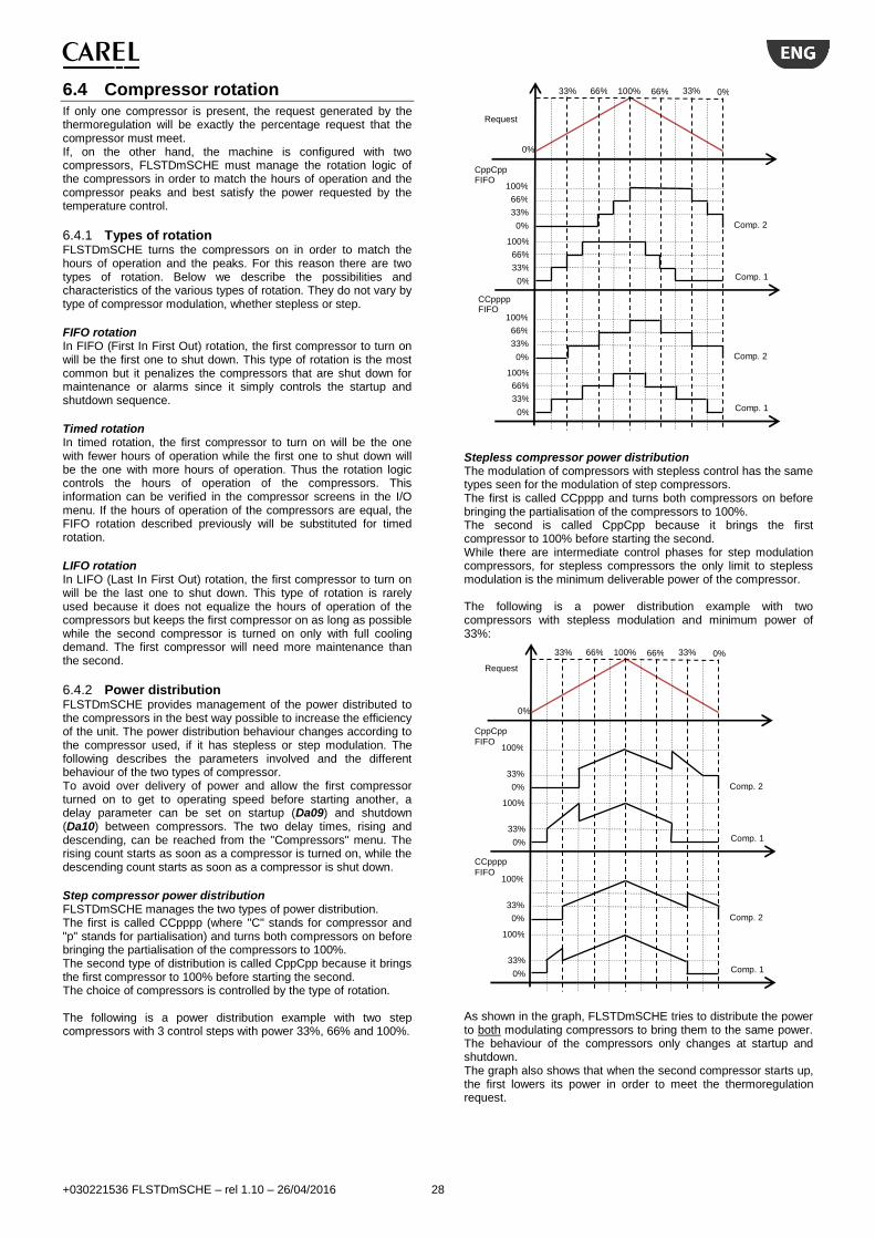
+030221536 FLSTDmSCHE – rel 1.10 – 26/04/2016 28
6.4 Compressor rotation If only one compressor is present, the request generated by the thermoregulation will be exactly the percentage request that the compressor must meet. If, on the other hand, the machine is configured with two compressors, FLSTDmSCHE must manage the rotation logic of the compressors in order to match the hours of operation and the compressor peaks and best satisfy the power requested by the temperature control.
6.4.1 Types of rotation FLSTDmSCHE turns the compressors on in order to match the hours of operation and the peaks. For this reason there are two types of rotation. Below we describe the possibilities and characteristics of the various types of rotation. They do not vary by type of compressor modulation, whether stepless or step.
FIFO rotation In FIFO (First In First Out) rotation, the first compressor to turn on will be the first one to shut down. This type of rotation is the most common but it penalizes the compressors that are shut down for maintenance or alarms since it simply controls the startup and shutdown sequence.
Timed rotation In timed rotation, the first compressor to turn on will be the one with fewer hours of operation while the first one to shut down will be the one with more hours of operation. Thus the rotation logic controls the hours of operation of the compressors. This information can be verified in the compressor screens in the I/O menu. If the hours of operation of the compressors are equal, the FIFO rotation described previously will be substituted for timed rotation.
LIFO rotation In LIFO (Last In First Out) rotation, the first compressor to turn on will be the last one to shut down. This type of rotation is rarely used because it does not equalize the hours of operation of the compressors but keeps the first compressor on as long as possible while the second compressor is turned on only with full cooling demand. The first compressor will need more maintenance than the second.
6.4.2 Power distribution FLSTDmSCHE provides management of the power distributed to the compressors in the best way possible to increase the efficiency of the unit. The power distribution behaviour changes according to the compressor used, if it has stepless or step modulation. The following describes the parameters involved and the different behaviour of the two types of compressor. To avoid over delivery of power and allow the first compressor turned on to get to operating speed before starting another, a delay parameter can be set on startup (Da09) and shutdown (Da10) between compressors. The two delay times, rising and descending, can be reached from the "Compressors" menu. The rising count starts as soon as a compressor is turned on, while the descending count starts as soon as a compressor is shut down.
Step compressor power distribution FLSTDmSCHE manages the two types of power distribution. The first is called CCpppp (where "C" stands for compressor and "p" stands for partialisation) and turns both compressors on before bringing the partialisation of the compressors to 100%. The second type of distribution is called CppCpp because it brings the first compressor to 100% before starting the second. The choice of compressors is controlled by the type of rotation. The following is a power distribution example with two step compressors with 3 control steps with power 33%, 66% and 100%.
Stepless compressor power distribution The modulation of compressors with stepless control has the same types seen for the modulation of step compressors. The first is called CCpppp and turns both compressors on before bringing the partialisation of the compressors to 100%. The second is called CppCpp because it brings the first compressor to 100% before starting the second. While there are intermediate control phases for step modulation compressors, for stepless compressors the only limit to stepless modulation is the minimum deliverable power of the compressor. The following is a power distribution example with two compressors with stepless modulation and minimum power of 33%:
As shown in the graph, FLSTDmSCHE tries to distribute the power to both modulating compressors to bring them to the same power. The behaviour of the compressors only changes at startup and shutdown. The graph also shows that when the second compressor starts up, the first lowers its power in order to meet the thermoregulation request.
CppCpp FIFO
Request
0%
33% 66% 100% 66% 33% 0%
Comp. 2
Comp. 1 0%
33%
66%
100%
0%
33%
66%
100%
CCpppp FIFO
Comp. 2
Comp. 1 0%
33%
66%
100%
0%
33%
66%
100%
CppCpp
FIFO
Request
0%
33% 66% 100% 66% 33% 0%
Comp. 2
Comp. 1 0%
33%
100%
0%
33%
100%
CCpppp
FIFO
Comp. 2
Comp. 1 0%
33%
100%
0%
33%
100%

+030221536 FLSTDmSCHE – rel 1.10 – 26/04/2016 29
6.4.3 Rotation for alarm In the event of an alarm for one compressor , the next available compressor will be turned on as a replacement if the request is high enough. For units with two circuits and prevention active in one circuit, the rotation will compensate for the limited compressor by increasing the request on the available compressor.
6.4.4 Forced rotation Some compressor manufacturers specify that in units with two compressors, they must be rotated after a certain amount of time in which one only is on, even if control has reached a stable point (parameter Da11). Besides keeping the hours of operation equalized, this procedure avoids the migration of refrigerant during long pause periods and keeps the compressor in temperature.
6.5 Pump-Down The purpose of the pump-down function is to reduce the quantity of refrigerant in the evaporator to limit the presence of liquid in suction during the compressor startup phase. Pump-down can be controlled by the electronic expansion valve (ExV) or the solenoid valve combined with the ExV valve. In general, the pump-down can be activated in two phases: at compressor start up or shut down. FLSTDmSCHE manages the pump-down in both phases. In the compressor shutdown phase it stops when the evaporation pressure reaches the pump-down end setpoint. In the compressor startup phase, the pump-down ends when the pressure difference between discharge and suction reaches the nominal value if prevention is enabled (automatically calculated by the shape fo the envelope) or the minimum evaporation pressure threshold is reached. In both pump-down management methods, if the threshold is not reached within a certain time, the procedure is considered complete. In this case, a pump-down not completed event is saved in the alarms log.
Note: The shutdown pump-down is also performed in the event of shutdowns for alarms that are not serious. It is not performed during defrosting.
6.5.1 Pump-down with ExV The use of the ExV to perform the pump-down phase allows slower closure compared to the solenoid valve, thus avoiding the pressure wave due to the movement inertia of the fluid ("water hammer") that, if it persists, could break the weaker devices affected by impulse overpressure. CAREL offers an UltraCap module that allows the valve to be closed following a blackout, ensuring the intercept of the liquid in any situation and thus allowing the solenoid valve to be omitted. Below we see how the pump-down procedure is performed with only the ExV:
In the pump-down, there are 6 control phases:
Comp. ExV Solenoid valve
1 OFF 0% ---
2
Start-up + Pump-Down
0% ---
3 Modulation SH control ---
4 Shut-down SH control ---
5 Minimum + Pump-Down
0% ---
6 OFF 0% ---
Whenever there is a solenoid valve, even if not used for the pump-down, it exactly follows the compressor behaviour, as shown in the graph.
The 6 control phases become the following:
Comp. ExV Solenoid valve
1 OFF Stand-by (open 25%) OFF
2
Start-up + Pump-Down
0% ON
3 Modulation SH Control ON
4 Shut-down SH Control ON
5 Minimum + Pump-Down
0% ON
6 OFF Stand-by (open 25%) OFF
6.5.2 Pump-down with ExV and solenoid The ExV can still coexist with the solenoid valve provided that this last remains open during the compressor shut down: this condition is automatically managed when configuring the presence of solenoid valve. If both valves are closed, the liquid between the two interceptions can cause an overpressure that is dangerous for the integrity of the valves themselves. Below we see how the pump-down procedure is performed with the ExV and solenoid present:
Request
Comp.
Evap.
Time [s]
ExV
1 2 3 4 5 6
Set PD
0%
Request
Comp.
Evap.
Solenoid valve
Time [s]
ExV
1 2 3 4 5 6
Set PD
0%
Standby position
Request
Comp.
Evap.
Solenoid valve
Time [s]
ExV
1 2 3 4 5 6
Set PD
0%
Standby position

+030221536 FLSTDmSCHE – rel 1.10 – 26/04/2016 30
In the pump-down, there are 6 control phases:
Comp. ExV Solenoid valve
1 OFF Stand-by (open 25%) OFF
2
Start-up + Pump-Down
Stand-by (open 25%) OFF
3 Modulation SH Control ON
4 Shut-down SH Control ON
5 Minimum + Pump-Down
0% ON
6 OFF Stand-by (open 25%) OFF
Note: When the selected EEV has an opening time greater than 3s, FLSTDmSCHE operates a small pre-opening of the valve before running the compressor in order to avoid to reach vacuum condition during startup procedure.
6.6 Compressor management FLSTDmSCHE manages screw type compressors with step or stepless modulation. There can be a maximum of 2 screw compressors, each managing up to 4 modulation valves on the power control slide. The flow diagram below shows the process for calculating the request to the compressors:
Note: For setup simplicity there are only parameters for one compressor and one circuit so all of the compressors and circuits in the unit will have the same settings.
6.6.1 Predefined compressors In the compressor menu the type of compressor can be selected from the following list:
Compressor manufacturer
Compressor model
Gas Manual version
Bitzer
CSH3 R134a
SH-170-4 i R407C
CSW R134a
R407C
CSVH R134a SP-160-2
Hanbell RC2 R134a HBME-RC2-10-A(500)
RefComp 134-S /-XS R134a EA-03-04-E
Frascold CXH R134a 21-01-2014
CXW R134a 21-01-2014
CXHIT R134a
CXWIT R134a
The choice of a certain type of compressor sets the following parameters depending on the technical specifications of the compressor manufacturers: 1. Valve data
Number of valves
Intermittent valve time
Impulse time for increase valves, for stepless modulation
Impulse time for decrease valves for stepless modulation
Valve behaviour during startup, control and shutdown.
2. Step modulation compressor data:
Step number
Starting procedure duration
Shutdown procedure duration
Power of the various steps
Steps activation delay
Minimum safety time limits 3. Stepless modulation compressor data:
First startup procedure phase duration
Second startup procedure phase duration
First shutdown procedure duration
Second shutdown procedure duration
Minimum power
Time to reach maximum power
Time to reach minimum power
Minimum safety time limits 4. Compressor envelope:
All characteristics of the compressor envelope shape
Maximum discharge temperature
Minimum discharge temperature If the CUSTOM compressor is set, all of these parameters (identified by code Dbnn) may be edited in the Compressor menu, otherwise they can only be displayed, without the possibility to change them.
6.6.2 Safety time control FLSTDmSCHE ensures the compressor safety timings as:
Minimum on time
Minimum off time, after controlled shut down
Minimum off time, after shut down due to alarm
Minimum time for consecutive startups These times are in the Compressor menu and can be changed by accessing with Service passord. The lower limit for changing the mentioned timings is pre-set according to the specifications of the compressor manufacturer. As described in the previous paragraph, these limits are set by default by the type of compressor and can be changed only after selecting a Custom type compressor.
6.6.3 Step modulation FLSTDmSCHE manages the step modulation of the screw compressors: divides the percentage request generated by the thermoregulation between the various compressors depending on the rotation logic and controls the compressor steps according to the below described parameters.
Step number This parameter (Db53) determines the number of steps that can be activated. These change according to the type of compressor.
Power of the various steps Each step is characterized by a parameter (Db54, Db55, Db56) that specifies its power. This allows fine control of the power requested by the thermoregulation according to the effective power of each step of the compressor. If the cooling power of the machine is not consistent with the power expressed by the compressor, the CUSTOM compressor can be set and the parameters changed according to the needs of the machine.
ON unit
OK unit on
Circuit 1
ON pump Flow alarm
Thermo-regulation
Rotation
BMS
Pump-Down
Envelope
prevention
Compressor control
Timings
Circuit 2
ExV
Temperature control
OK pump active
0…100.0%
0…100.0%
0…100.0%
0…100.0%
0…100.0%
0..100.0%
Unit alarms
Circuit alarms
OK
OK

+030221536 FLSTDmSCHE – rel 1.10 – 26/04/2016 31
Startup procedure duration This parameter (Db50) specifies the duration of the compressor startup phase in which the valves have a preset behaviour to allow the compressor to reach the operating conditions.
Shutdown procedure duration This parameter (Db51) specifies the duration of the compressor shutdown phase in which the valves have a preset behaviour to allow the compressor to reach the minimum power. Respecting this phase, on the next compressor startup, the slide will be at the minimum power and thus startup will be less heavy for the motor.
Step activation delay To allow proper management of the compressor control slide, there are delays between the various steps in the power increase phase. These parameters (Db57, Db58, Db59) are dictated by the technical features of the compressors and are thus independent of the plant control. To slow down the steps activation it is possible to set the parameter (Da91). To slow down or speed up the activation or shut down of the compressors according to the temperature, the PID parameters and delays between the compressors must be changed in the Plant ad Compressor menus.
Step deactivation delay To allow proper management of the compressor control slide, there are 20s fixed delays between the various steps in the power decrease phase. These delays are dictated by the technical features of the compressors and are thus independent of the plant control.
Valve management FLSTDmSCHE makes it possible to have different valve management depending on the compressor phase. The following controller phases exist:
1. Startup 2. Step 1 3. Step 2 4. Step 3 (if present) 5. Step 4 (if present) 6. Shutdown or compressor off
As previously described, the maximum number of valves is 4 (see digital outputs par.)
Control procedure The previously described parameters make the compressor perform an activation procedure according to the compressor manufacturer's specifications. The graph below shows how the request from the control interacts with the control of the compressor during startup. In the example, the compressor has 3 steps of equal power (33%-66%-100%).
As shown in the graph, during the first phase the compressor is in startup and the regulation has no effect on it. Then, when the request is rising, the compressor must respect the activation times between the steps to avoid abrupt power changes that could damage the circuit and the compressor itself. During the shutdown phase, which is hypothetically immediate in the graph, the delay between steps is not respected and the shutdown phase has started. If during the shutdown phase the request goes above the minimum, the compressor goes back to following the control phases.
6.6.4 Stepless modulation FLSTDmSCHE manages the stepless modulation of the screw compressors. The percentage request generated by the thermoregulation is divided between the various compressors depending on the rotation logic, then each compressor is modulated according to the parameters described below.
Minimum power This parameter (Db65) expresses the minimum power percentage that the compressor can deliver. When the request reaches this value, the compressor can begin the startup phase.
First starting procedure phase duration This parameter (Db50) specifies the duration of the compressor startup phase in which the valves have a preset behaviour to allow the compressor to reach the operating conditions.
Second starting procedure phase duration (Parameter Db61). Some compressors have two startup phases with two distinct behaviours of the valves during those phases. The first phase is needed to bring the compressor to the minimum deliverable power (generally 25%) while the second phase is needed to bring the compressor to the power from which it can start to regulate (generally 50%).
First shutdown procedure duration This parameter (Db51) expresses the time that the compressor uses to reach the minimum power in control (generally 50%). Respecting this phase, the compressor can turn off in ramp using the second shutdown phase.
Second shutdown procedure duration This parameter (Db63) specifies the duration of the compressor shutdown phase in which the valves have a preset behaviour to allow the compressor to reach the minimum deliverable power (generally 25%). Respecting this phase, on the next compressor startup, the slide will be at the minimum power and thus startup will be less burdensome for the motor.
Time to reach maximum power In screw compressors with stepless modulation the position of the slide cannot be defined through direct measurement thus the power delivered by the compressor must be estimated. For this reason, FLSTDmSCHE implements a calculation logic for the power delivered by the compressor based on the time to reach the maximum power (Db67). This parameter indicates the time needed for the slide to move from the minimum power position to the maximum one (100%) keeping the charge valve active. Since the valve is impulse controlled, the algorithm calculates the percentage of variation of the screw compressor capacity at each activation of the pulsating valve for increase. The valve will then continue to pulse until the percentage requested by the thermoregularion is reached (see following graph). Before re-activating the valve, the algorithm checks if activation could cause over delivery of the power and in this case the compressor goes into stand-by. When the calculated power arrives at 100%, the stepless increase valve continues to load in order to keep the slide at the limit switch. Due to the number of activations resulting from management of the pulsating valves, the use of controllers with SSR relays is recommended (see digital outputs par.).
Time to reach minimum power Along with the time to reach the maximum power, there is also the time to reach the minimum power (Db66). This parameter indicates the time needed at the slide to switch from the maximum power position (100%) to the minimum one, keeping the charge valve active. The time to reach the minimum power from reaching
Stages
Request
0%
33% 66% 100%
0%
33%
66%
100%
Time Start Db50
Delay step 1-2
Db57
Delay step 2-3
Db58
Time off
Db51
0%
Request
Valve
Increase
Power
Standby Increase
Standby

+030221536 FLSTDmSCHE – rel 1.10 – 26/04/2016 32
the maximum power must be distinguished as some compressors use less time for the discharge phase. Since the valve is impulse controlled, the algorithm calculates the percentage of variation of the screw compressor capacity at each activation of the pulsating valve for decrease. The valve will then continue to pulse until the percentage requested by the thermoregularion is reached (see following graph). Before re-activating the valve, the algorithm checks if activation could cause under delivery of the power and in this case the compressor goes into stand-by. When the calculated power reaches the minimum, the stepless decrease valve continues to discharge to keep the slide in the minimum position. Due to the number of activations resulting from management of the pulsating valves, the use of controllers with SSR relays is recommended (see digital outputs par.).
Pulsing valve management As previously described, to increase or decrease the compressor capacity, the charge or discharge valves must be pulsed. The parameters for managing these valves are as follows:
1. Increase valve impulse time (Db02) 2. Decrease valve impulse time (Db03) 3. Minimum valve rest time (Da32) 4. Maximum valve rest time (Da33).
The valve impulse times (Db02, Db03) are defined by the compressor model and are constant for the entire compressor control phase. These times can be set only with the CUSTOM compressor type. The minimum and maximum rest times for the valves are parameters that can be changed in the Compressors menu. The rest time varies according to the distance of the percentage value requested from the power delivered. The following is a rest time modulation example of the increase valve:
NB: If the absolute difference between Request and Power remains >= 30%, the duration of the activation of the valves to increase/decrease is multiplied by 2 after 20s, by 3 after 40s, by 4 after 60s. As soon as the difference drops below 30%, the value of the multiplier back to 1.
Valve management FLSTDmSCHE makes it possible to have different valve management depending on the compressor phase. The controller phases are as follows:
1. First startup phase 2. Second startup phase 3. Increase power 4. Stand-by 5. Decrease power 6. First shutdown phase 7. Second shutdown phase or compressor off
As previously described, the maximum number of valves is 4 (see digital outputs par.).
Control procedure The previously described parameters make the compressor perform an activation procedure according to the compressor manufacturer's specifications. The graph below shows how the regulation request interacts with the control of the compressor during startup. In the example, the compressor has a minimum power of 33%.
As shown in the graph, during the first phase the compressor is in startup and the control has no effect on it. Then, when the request is rising, the power of the circuit rises according to the activation times of the charge valve. If the request is faster than the movement of the slide, as we can see in the graph, the compressor will be delayed compared to the request. During the shutting down phase, the compressor will proceed with the power decrease phase. If, as shown in the graph, the request decrease is immediate, the compressor will enter the shutting down phase without completely following the decrease phase. If during the shutdown phase the request goes above the minimum, the compressor goes back to following the modulation phases, aborting the shut-down.
6.6.5 Inverter modulation FLSTDmSCHE manages the modulation of the screw compressors with integrated frequency inverter. The percentage request generated by the thermoregulation is divided between the various compressors depending on the rotation logic, then each compressor is modulated according to the parameters described below.
Minimum frequency This parameter (Dc06) expresses the minimum frequency the inverter can deliver. When the request reaches this value, the compressor can begin the startup phase.
Maximum frequency This parameter (Dc07) expresses the maximum frequency the inverter can deliver. It’s the delivered frequency when the request reach 100%. The following is an example of inverter compressor modulation:
Request
Valve
Increase
Power
Standby Decrease
Request
Valve Increase
Power
Min OFF Da32
Max OFF Da33
Comp. stepless
Request
0%
33% 100%
0%
33%
100%
Time Start Db50
Time Off
Db51
0%
Time Increase
Db67
Time Decrease
Db66
Request 100%
Max Freq. Dc07
Frequency [Hz]
Min Freq. Dc06
Standby
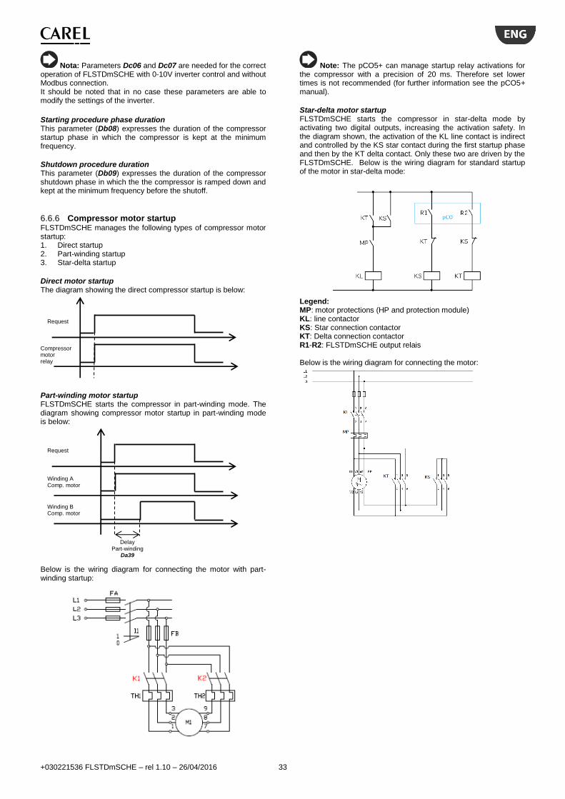
+030221536 FLSTDmSCHE – rel 1.10 – 26/04/2016 33
Nota: Parameters Dc06 and Dc07 are needed for the correct operation of FLSTDmSCHE with 0-10V inverter control and without Modbus connection. It should be noted that in no case these parameters are able to modify the settings of the inverter.
Starting procedure phase duration This parameter (Db08) expresses the duration of the compressor startup phase in which the compressor is kept at the minimum frequency.
Shutdown procedure duration This parameter (Db09) expresses the duration of the compressor shutdown phase in which the the compressor is ramped down and kept at the minimum frequency before the shutoff.
6.6.6 Compressor motor startup FLSTDmSCHE manages the following types of compressor motor startup: 1. Direct startup 2. Part-winding startup 3. Star-delta startup
Direct motor startup The diagram showing the direct compressor startup is below:
Part-winding motor startup FLSTDmSCHE starts the compressor in part-winding mode. The diagram showing compressor motor startup in part-winding mode is below:
Below is the wiring diagram for connecting the motor with part-winding startup:
Note: The pCO5+ can manage startup relay activations for the compressor with a precision of 20 ms. Therefore set lower times is not recommended (for further information see the pCO5+ manual).
Star-delta motor startup FLSTDmSCHE starts the compressor in star-delta mode by activating two digital outputs, increasing the activation safety. In the diagram shown, the activation of the KL line contact is indirect and controlled by the KS star contact during the first startup phase and then by the KT delta contact. Only these two are driven by the FLSTDmSCHE. Below is the wiring diagram for standard startup of the motor in star-delta mode:
Legend: MP: motor protections (HP and protection module) KL: line contactor KS: Star connection contactor KT: Delta connection contactor R1-R2: FLSTDmSCHE output relais Below is the wiring diagram for connecting the motor:
Request
Compressor motor relay
Request
Winding A Comp. motor
Winding B Comp. motor
Delay Part-winding
Da39

+030221536 FLSTDmSCHE – rel 1.10 – 26/04/2016 34
The activation sequence is as follows:
The indirect control technique for the line contactor allows double breaking of the arc during the first phase of the star-delta switch and thus shorter switching times. In fact, the activation sequence for the auxiliary/main contacts is such that, when closing, first the main contacts (power) close and then the auxiliary ones while, when opening, first the auxiliary ones open and then the power contacts. This sequence ensures the participation of both star (KS) and line (KL) contactors to extinguish the arc which is thus distributed over a double distance in air, with reduced arc extinction times. Given that the switch delay between the star and delta should be as short as possible (to prevent excessive slow down of the motor - reaching currents near startup direct during delta insertion) but at the same time ensuring arc extinction (to avoid even higher currents as a result of the short circuit due to the arc present in the centre of the star), since the proposed system reduces the arc extinction time it is possible to use significantly shorter times resulting in a more fluid startup. When setting the star-delta switching time, the mechanical delay time in closing the remote line switch must be considered. It is shown in the graph with A letter (~15ms): for example, if 25 ms is set, the overall time will be 40 ms.
Request
Compressor
Relay R1
Compressor Relay R2
Star time
Da41 Delay
Star-delta
Da40
Line
Star
Delta
A A A

+030221536 FLSTDmSCHE – rel 1.10 – 26/04/2016 35
6.7 Eco control and liquid injection The controller manages two distinct digital outputs for controlling the Eco valve and the injection of liquid in the compressor. Both outputs are active only with the compressor on.
6.7.1 Eco valve The Eco valve allows the cooling power to be increased and the compressor performance to be improved through a subcooling circuit or a two stage refrigerant expansion. Its efficiency is at a maximum especially with high condensing temperatures. Thus the condensing temperature and the compressor power are controlled, as shown in the graph below:
The Eco function is active if the following conditions are true: 1. The compressor is on for at least 300 seconds. 2. The condensing temperature is greater than the setpoint for
the Eco (Da34); 3. The compressor power is greater than the minimum power
specified for Eco operation (Da36); 4. The compressor is within the envelope operating limits
regarding the high condensing temperature, high current and high evaporation temperature zones;
5. At least 300 seconds have passed since the previous deactivation of the Eco valve.
6.7.2 Liquid injection valve The liquid injection valve cools the compressor during operation with high discharge temperatures and thus mainly in high condensation temperature and low evaporation temperature conditions (zone 2 of the envelope). The discharge temperature is thus controlled and when it exceeds a threshold (Da37), the liquid injection valve is activated. In descent, as for the Eco valve, there is a differential (Da38) to avoid sudden startups and shutdowns.
6.8 Compressor protections The operating limits (hereafter defined as envelope) of the screw compressors with step modulation or stepless modulation (inverter too) are controlled. This control cannot be disabled in order to prevent the compressor from working outside of the safety limits dictated by the manufacturer. All of the compressors inserted thus contain the envelope data. Besides the operating limits specified by the manufacturer, there is the possibility of customizing the maximum condensation (Da13) and minimum evaporation (Da12) thresholds. These thresholds are considered only if they are more restrictive than the operating limits. The envelope data for the previously listed compressors are preset but this data can be changed by setting a Custom compressor. The envelope data must then be entered according to the manufacturer's specification using the parameter codes shown in the table below. The choice of a compressor with a type of gas is not binding in the choosing the refrigerant type. It is best to verify that the gas used has the same envelope as the gas indicated in the compressor parameter. The description of the work zones of a generic envelope are shown below:
Zone Par. Description
1 Zone inside the operating limits (the prevention is active to avoid going outside the limits)
2
Db89 (1)
Db90 (1)
Db91 (1)
Db92 (1)
Max compression ratio
3 Db72 (2)
Max condensation pressure
3 Eco Db75 (3)
Max condensation pressure with Eco active
3 Custom
Da13 Max condensation pressure custom threshold
4
Db77 (1)
Db78 (1)
Db79 (1)
Db80 (1)
Max motor current
5 Db74 (2)
Max evaporation pressure
5 Eco Db76 (3)
Max evaporation pressure with Eco active
6
Db81 (1)
Db82 (1)
Db83 (1)
Db84 (1)
Min compression ratio
7
Db85 (1)
Db86 (1)
Db87 (1)
Db88 (1)
Min differential pressure
8 Db71 (2)
Min condensation pressure
9 Db73 (2)
Min evaporation pressure
9 Custom
Da12 Min evaporation pressure custom threshold
For each work zone outside the envelope, the alarm that turns off the compressor can be triggered with different delays that can be set in the Compressor menu. The condensation high pressure limit is determined from the minimum between:
the nominal compressor threshold (Db72),
the threshold that can be set by Service (Da13),
the nominal eco threshold if enabled (Db75). The evaporation high pressure limit is determined from the minimum between:
the nominal compressor threshold (Db74),
the nominal eco threshold if enabled (Db76). The evaporation low pressure limit for prevention is determined from the maximum of:
the nominal compressor threshold (Db73),
the threshold that can be set by Service (Da12), Besides the operating limits dictated by the envelope shape, there is an operating limit on the discharge temperature (Db99), that turned off the compressor.
Notes: (1)
With custom compressor, the control can be disabled by entering zero for both parameters; (2)
With custom compressor, the primary envelope limits cannot be disabled. (3)
With custom compressor, the Eco limits can be disabled if the values are set to less than or equal to zero.
Power
Cond.
Eco
Diff.
Da35
Set Da34
Set Da36
Condensing temperature
Evaporating temperature
1
2
3
4
5
6
7
8
9
3 Eco
5
Eco
3 Custom 9 C
usto
m

+030221536 FLSTDmSCHE – rel 1.10 – 26/04/2016 36
6.9 Compressor alarm prevention The suction and discharge pressures determine a working point and depending upon the zone, the control perform corrective actions to maintain or bring the compressor within the operating limits. These actions can be disabled through the prevention enabling parameter (Da80).
6.9.1 Prevention actions The description of the work zones of a generic envelope are shown below:
Zone Description
1 Zone within operating limits
2 Prevention for high compression ratio
3 Prevention for high condensation pressure
4 Prevention for high motor current
5 Prevention for high evaporation pressure
6 Prevention for low compression ratio
7 Prevention for low differential pressure
8 Prevention for low condensation pressure
9 Prevention for low evaporation pressure
To allow the compressor to work inside the envelope, specific prevention actions are performed through the control of the compressor power, the speed of the condenser fans and the opening of the ExV. In particular, the actions on the compressor power are:
Decrease the speed for increasing/decreasing the power request coming from the thermoregulation (only for stepless compressors);
Limit/increase the compressor power. The action on the ExV valve is performed by varying the MOP threshold whose algorithm follows the set (evaporation temperature), decreasing the valve opening and thus reducing the mass capacity of the refrigerant and lowering the evaporation temperature. The control actions on the power variation speed start when the working point is 7°C from the envelope border. These actions are only possible with stepless compressors. In case of step compressor the only possible action on the compressor are to limit/increase its power, this is done when the working poing cross the envelope border. Below we examine the various prevention actions towards the operating limits.
Prevention for high compression ratio (zone 2) The high compression ration is a thermal limit of the compressor. Therefore, the “outside of the envelope” status is simply signalled without shutting down the compressor. As prevent action, compressor power is decreased. Since the critical conditions consists in high compressor discharge temperatures, the management of the compressor power directly controls the related probe. To control the discharge temperature, a specific algorithm intervenes, initially slowing down the power increase until it stops when the control set is reached (5° C below the maximum limit). If the temperature increases further, the algorithm manages the power reduction gradually and slowly, imitating the behaviour of the thermal inertia of the compressor.
Device Description
Compressor 1. Decrease of power increase speed 2. Power limitation
ExV -
Fan -
Prevention for high condensation pressure (zone 3)
Device Description
Compressor 1. Decrease of power increase speed 2. Power limitation
ExV -
Fan -
Prevention for high motor current (zone 4)
Device Description
Compressor 1. Decrease of power increase speed 2. Power limitation
ExV MOP with specific algorithm
Fan -
Prevention for high evaporation pressure (zone 5)
Device Description
Compressor Decrease of power decrease speed
ExV MOP
Fan -
Prevention for low differential pressure (zone 6)
Device Description
Compressor 1. Decrease of power decrease speed 2. Power increase
ExV Variable MOP
Fan Condensation set point increase / evaporation set point decrease
Prevention for low compression ratio (zone 7)
Device Description
Compressor 1. Decrease of power decrease speed 2. Power increase
ExV Variable MOP
Fan Condensation set point increase / evaporation set point decrease
Prevention for low condensation pressure (zone 8)
Device Description
Compressor 1. Decrease of power decrease speed 2. Power increase
ExV -
Fan -
Prevention for low evaporation pressure (zone 9) The evaporation low pressure limit for prevention is determined from the maximum between:
the nominal compressor threshold (Db73),
the threshold eventually set by Service (Da12),
Temperature
condensation
Temperature evaporation
1
2
3
4
5
6
7
8
9
1. Reduction in power increase speed (progressive)
2. Power reduction 5.0°C
10.0°C
Alarm
Discharge temperature
Max limit Db99
Normal operation

+030221536 FLSTDmSCHE – rel 1.10 – 26/04/2016 37
the antifreeze limit according to the mode (A028 in cold and C037 in hot with water/water unit).
Device Description
Compressor 1. Decrease of power increase speed 2. Power limitation
ExV -
Fan -
6.10 Compressor alarms management Controlled compressor shutdown The control algorithm calls for two types of compressor shutdown depending on severity:
1. Immediate compressor shutdown; 2. Controlled compressor shutdown.
Immediate compressor shutdown is activated in the event of critical alarms and alarms that require direct intervention on the compressor contactor coil (see alarms table for details). Immediate compressor shutdown requires a greater amount of time to reset the slide position, which can be defined through the specific parameter (Da06). Controlled compressor shutdown is activated for all alarm conditions that are not an immediate danger and thus allow shutdown of the compressor itself using the correct procedure (immediate shutdown should be kept to a minimum). This procedure limits the presence of liquid and ensures less resistant torque at the next compressor startup. Controlled shutdown simultaneously activates the shut-down procedure (continuous activation of the discharge valve for the shutdown time - Db51) and the pumpdown (if enabled). The procedure is finished when the first of the two actions is completed. The compressor will be available again as soon as the minimum nominal off time has passed (Da05).
Startup-Running delay of the compressor Compressor startup is a critical phase and for this reason FLSTDmSCHE has differentiated control for certain alarms to exceed the transition phase from compressor startup and allow it to reach operating condition. The alarms that use this characteristic are the following:
Low pressure from pressure switch alarm
Oil level alarm
High evaporation pressure alarm
Low pressure ratio alarm
Low pressure delta alarm
Low condensation pressure alarm
Low evaporation pressure alarm There are two types of delays for these alarms:
Startup delay
Running delay
The alarm condition is ignored with the compressor off and during startup. Once the startup phase is complete, the operation phase is entered and the alarm is trigged when the delay is exceeded.
It will behave as follows:
6.11 EVD EVO device The EVD EVO driver for the electronic expansion valve is a fundamental device in the FLSTDmSCHE controller. It allows safe management of the compressor and circuit and reads all of the essential probes for regulating suction superheat, managing the work zone and the discharge temperature. For each pCO5+ board, up to two single type drivers are controlled, each managing one circuit. The driver and controller communicate using the CAREL protocol with a serial speed of 19200bps on the FB2 serial port of the pCO.
6.11.1 FLSTDmSCHE logic for ExV control The FLSTDmSCHE controller does the following:
Manages communication with the EVD EVO drive (reading and send parameters via serial port);
Completely displays the EVD parameters in the Exv menu, divided by type of regulation;
Sends the cooling capacity of the compressor to the driver. If the driver is offline, the compressor in the circuit involved will be immediately turned off without the shutdown procedure.
Control parameter management The controller differentiates the parameters between the various driver control statuses:
Control in chiller mode;
Control in heat pump mode. Therefore for all control parameters there is a series for chiller mode and a series for heat pump mode. The following are the parameters that are differentiated according to the operating mode:
Superheat parameters (Setpoint and PID);
Alarm thresholds and integral actions for LOP, MOP and Low SH alarms.
6.11.2 EVD EVO logic for ExV control The driver does the following:
Valve activation;
Suction superheat control;
Alarm and low superheat control (Low SH);
Alarm and minimum evaporation temperature control (LOP);
Alarm and maximum evaporation temperature control (MOP);
Alarm and high condensation temperature control (HighTCond);
Control of the cooling capacity sent from the controller, that sets the valve position according to the compressor control status.
Notes: For further information see the Individual EVD EVO manual code +0300005IT.
Compressor
Alarm
Condition Alarm
Startup delay Running delay
Running delay
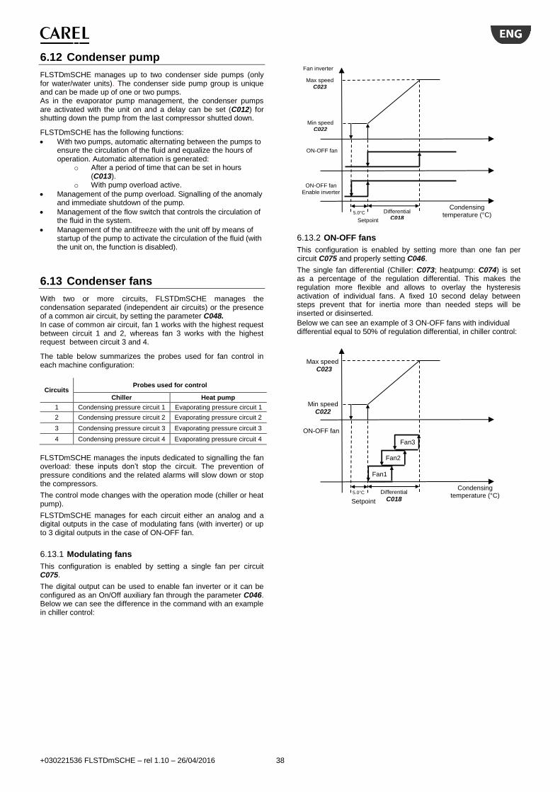
+030221536 FLSTDmSCHE – rel 1.10 – 26/04/2016 38
6.12 Condenser pump
FLSTDmSCHE manages up to two condenser side pumps (only for water/water units). The condenser side pump group is unique and can be made up of one or two pumps. As in the evaporator pump management, the condenser pumps are activated with the unit on and a delay can be set (C012) for shutting down the pump from the last compressor shutted down.
FLSTDmSCHE has the following functions:
With two pumps, automatic alternating between the pumps to ensure the circulation of the fluid and equalize the hours of operation. Automatic alternation is generated:
o After a period of time that can be set in hours (C013).
o With pump overload active.
Management of the pump overload. Signalling of the anomaly and immediate shutdown of the pump.
Management of the flow switch that controls the circulation of the fluid in the system.
Management of the antifreeze with the unit off by means of startup of the pump to activate the circulation of the fluid (with the unit on, the function is disabled).
6.13 Condenser fans
With two or more circuits, FLSTDmSCHE manages the condensation separated (independent air circuits) or the presence of a common air circuit, by setting the parameter C048. In case of common air circuit, fan 1 works with the highest request between circuit 1 and 2, whereas fan 3 works with the highest request between circuit 3 and 4.
The table below summarizes the probes used for fan control in each machine configuration:
Circuits Probes used for control
Chiller Heat pump
1 Condensing pressure circuit 1 Evaporating pressure circuit 1 1
2 Condensing pressure circuit 2 Evaporating pressure circuit 2
3 Condensing pressure circuit 3 Evaporating pressure circuit 3
4 Condensing pressure circuit 4 Evaporating pressure circuit 4
FLSTDmSCHE manages the inputs dedicated to signalling the fan overload: these inputs don’t stop the circuit. The prevention of pressure conditions and the related alarms will slow down or stop the compressors.
The control mode changes with the operation mode (chiller or heat pump).
FLSTDmSCHE manages for each circuit either an analog and a digital outputs in the case of modulating fans (with inverter) or up to 3 digital outputs in the case of ON-OFF fan.
6.13.1 Modulating fans
This configuration is enabled by setting a single fan per circuit C075.
The digital output can be used to enable fan inverter or it can be configured as an On/Off auxiliary fan through the parameter C046. Below we can see the difference in the command with an example in chiller control:
6.13.2 ON-OFF fans
This configuration is enabled by setting more than one fan per circuit C075 and properly setting C046.
The single fan differential (Chiller: C073; heatpump: C074) is set as a percentage of the regulation differential. This makes the regulation more flexible and allows to overlay the hysteresis activation of individual fans. A fixed 10 second delay between steps prevent that for inertia more than needed steps will be inserted or disinserted.
Below we can see an example of 3 ON-OFF fans with individual differential equal to 50% of regulation differential, in chiller control:
Setpoint
Min speed C022
Max speed C023
Differential C018
Condensing temperature (°C)
Fan inverter
ON-OFF fan
ON-OFF fan
Enable inverter
5.0°C
Setpoint
Min speed C022
Max speed C023
Differential
C018
Condensing temperature (°C)
ON-OFF fan
5.0°C
Fan2
an
Fan1
Fan3
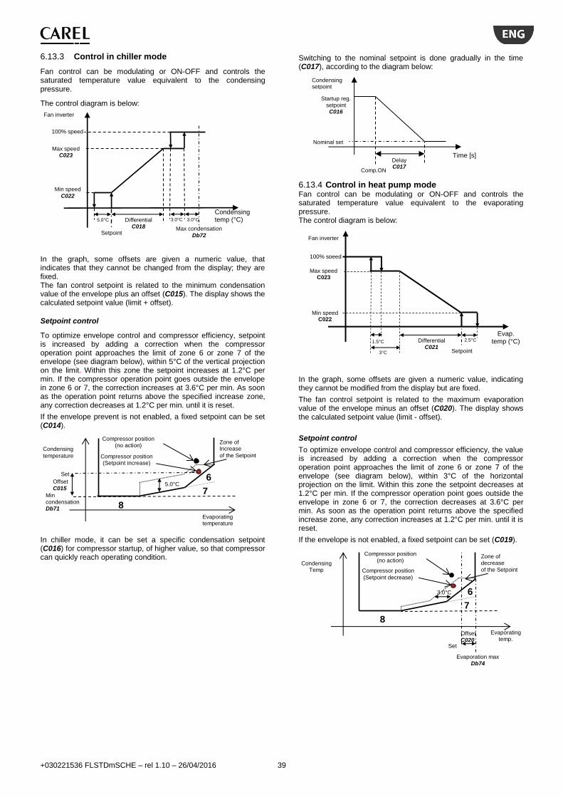
+030221536 FLSTDmSCHE – rel 1.10 – 26/04/2016 39
6.13.3 Control in chiller mode
Fan control can be modulating or ON-OFF and controls the saturated temperature value equivalent to the condensing pressure.
The control diagram is below:
In the graph, some offsets are given a numeric value, that indicates that they cannot be changed from the display; they are fixed. The fan control setpoint is related to the minimum condensation value of the envelope plus an offset (C015). The display shows the calculated setpoint value (limit + offset).
Setpoint control
To optimize envelope control and compressor efficiency, setpoint is increased by adding a correction when the compressor operation point approaches the limit of zone 6 or zone 7 of the envelope (see diagram below), within 5°C of the vertical projection on the limit. Within this zone the setpoint increases at 1.2°C per min. If the compressor operation point goes outside the envelope in zone 6 or 7, the correction increases at 3.6°C per min. As soon as the operation point returns above the specified increase zone, any correction decreases at 1.2°C per min. until it is reset.
If the envelope prevent is not enabled, a fixed setpoint can be set (C014).
In chiller mode, it can be set a specific condensation setpoint (C016) for compressor startup, of higher value, so that compressor can quickly reach operating condition.
Switching to the nominal setpoint is done gradually in the time (C017), according to the diagram below:
6.13.4 Control in heat pump mode Fan control can be modulating or ON-OFF and controls the saturated temperature value equivalent to the evaporating pressure. The control diagram is below:
In the graph, some offsets are given a numeric value, indicating they cannot be modified from the display but are fixed.
The fan control setpoint is related to the maximum evaporation value of the envelope minus an offset (C020). The display shows the calculated setpoint value (limit - offset).
Setpoint control
To optimize envelope control and compressor efficiency, the value is increased by adding a correction when the compressor operation point approaches the limit of zone 6 or zone 7 of the envelope (see diagram below), within 3°C of the horizontal projection on the limit. Within this zone the setpoint decreases at 1.2°C per min. If the compressor operation point goes outside the envelope in zone 6 or 7, the correction decreases at 3.6°C per min. As soon as the operation point returns above the specified increase zone, any correction increases at 1.2°C per min. until it is reset.
If the envelope is not enabled, a fixed setpoint can be set (C019).
Setpoint
Min speed
C022
Max speed C023
100% speed
Differential C018
Condensing temp (°C) 3.0°C
Fan inverter
5.0°C
Max condensation
Db72
3.0°C
8
Condensing
temperature
Evaporating temperature
6
7
Set
Offset
C015
Compressor position (no action)
Zone of Increase
of the Setpoint
Min condensation Db71
5.0°C
Compressor position (Setpoint increase)
Delay C017
Startup reg. setpoint C016
Time [s]
Condensing setpoint
Nominal set
Comp.ON
Min speed C022
100% speed
Differential C021
Fan inverter
Setpoint
Max speed C023
Evap. temp (°C) 2.5°C 1.5°C
3°C
8
Condensing Temp
Evaporating temp.
6
7
Set
Offset C020
Compressor position (no action)
Zone of decrease
of the Setpoint
Evaporation max Db74
3.0°C
Compressor position (Setpoint decrease)

+030221536 FLSTDmSCHE – rel 1.10 – 26/04/2016 40
6.14 Free-Cooling The Free-Cooling (FC) function can be enabled (parameter A044) on air-water unit, Chiller only, provided with air to water heat exchanger coils upstream of the condenser coils and modulating control of the fans. When the outside air temperature is low enough to cool the water that enters into the unit, Free-Cooling is enabled, the water undergoes a cooling from outside air before entering the evaporator.
The ventilation is controlled by the condensing value as long as the circuit compressor is active; as soon as the compressor shuts down the ventilation follows the request of the thermostatic regulation.
6.14.1 Dynamic gain of FC regulation This particular function allows to manage the balancing of capacity between Free-cooling battery and evaporator: this optimization offers best performance in terms of regulation stability and smoothness.
Diagram shows the ideal behaviour of FC regulation gain related proportionally to its capacity; “Design DeltaT FC” is the value of temperature difference (water inlet - ambient) that is needed to cover the nominal capacity of the unit, using free-cooling coils only. The “FC gain” obtained value is used to adapt the assignment of regulation ramp to the different sources of cooling, as shown on following diagram.
The result is a perfect balancing between the capacity of FC coils and evaporator, so that to maintain the same proportionality in each “capacity working point”, that is same reaction to same temperature variation with regardless to the load percentage.
6.14.2 FC efficacy control This control allows FLSTDmSCHE to start the compressors when the sole use of free cooling coil fails to bring water to the setpoint despite external conditions allow operation in full FC. When this happens it is possible that some malfunction in the free cooling device are present and therefore it is necessary to start the compressors and disable the FC in order to ensure operation of the unit. The anomaly is signaled by the alarm code 204.
6.15 Defrost During heat pump operating in air/water units, the external exchanger (coil) works as an evaporator. If the outside temperature is low, frost may form on the coil itself, resulting in a reduction in machine efficiency. In this case, it is best to activate the defrost function to free the exchanger of frost and reset the machine to maximum efficiency conditions. Activation of defrost depends on the value of the reference sensor (pressure transducer, low pressure side) and any delay (C030) from when the activation threshold (C024) was exceeded as shown in the figure below:
If during defrost delay the low pressure value does not exceed the reset threshold, the procedure will start. Defrost ends when the reference sensor (pressure transducer, high pressure side) exceeds the end defrost threshold.
6.15.1 Defrost procedure The figure below shows how the various components of the circuit and defrost phases are managed.
The description of the control phases follows:
Water IN temp – ambient air temp. (°C) 1.5°C
Free-Cooling
FC Activat. Delta
A045
ON
OFF
Water IN temp – ambient air temp. (°C)
Free-Cooling capacity
Design DeltaT FC A046
100%
0%
FC activat. DT A044
FC gain
1.5°C
10%
FC
gain Regulating
ramp
Regulation capacity
100%
100%
0%
0%
FC
gain
Regulating compressor
ramp
Regulating FC ramp
Time [s]
Evaporation
[°C]
End threshold Defrost
C026
Set threshold
C024
Condensation
Evaporation
Delay C030
Reset threshold C025
Start Defrost
End Defrost
Defrost request
Comp. Power
Cycle inversion
Fan
Time [s]
1 2 3 4 5 6 7

+030221536 FLSTDmSCHE – rel 1.10 – 26/04/2016 41
Check defrost entry (1)
Once defrost start condition is verified according to the criteria previously described, there is a parameter (C030) to delay the entry of the circuit in the defrost phase.
Compressor decrease in defrost entry (2)
In this phase the compressor decreases its power to reach the set defrost entry percentage (C028), during the fridge cycle inversion phase. This procedure has a minimum duration that is half the inversion time (C027). If during this time the compressor has not reached the set point, for example for stepless compressors that need more time in order to reach a certain power, the time is then increased.
If the set point during the cycle inversion procedure is set at 0%, the compressor will proceed with the shutdown phase and shut down. The compressor safety times are respected.
If the cycle inversion time is set to zero, the phase will only last for the amount of time needed to bring the compressor to the input setting for the defrost procedure.
The other circuit control devices, such as cycle inversion valve and fans, continue to regulate in heat pump mode.
Compressor increase in defrost entry (3)
The 4-way valve is positioned in chiller mode to perform the defrost. The fans shut off and the compressor starts to increase its power to reach the 100% fixed set point during defrost. The duration of the phase depends on the cycle inversion time (C027) and the time needed for the compressor to turn on if it was off.
During the defrost phase, the fans remain off and can only switch on to avid the condensation temperature exceedes the high pressure threshold.
Defrost phase (4)
Real defrosting starts in phase 4 where the compressor delivers full power to defrost the external coil.
The minimum defrost time, maximum defrost time and time between two defrost cycles are activated in this phase.
The minimum time in defrost is necessary to prevent the defrost cycle from not lasting long enough, performing a partial defrost of the exchanger.
The maximum defrost time is necessary to prevent the defrost procedure from lasting too long, blocking the production of hot water required by the utilities.
The time between two defrost cycles is needed to keep the unit from entering defrost too often and to allow the machine to partly satisfy the request.
The defrost phase stops for the previously described pressure conditions and time. If the compressor shuts off during the phase, the timers are reset and the circuit remains in the defrost cycle until the compressor starts again and completes it.
Compressor decrease in defrost outgoing (5)
This procedure has a minimum duration that is half the inversion time. If during this time the compressor has not reached the set point, for example for stepless compressors that need more time in order to reach a certain power, the time is then increased.
If the set point during the cycle inversion procedure is set at 0%, the compressor will proceed with the shutdown phase and shut down.
The compressor safety times are respected. If the cycle inversion time is set to zero, the phase will only last for the amount of time needed to bring the compressor to the output setting for the defrost procedure.
In this phase the fan is off and activated only to prevent high pressure and the cycle inversion valve stays in chiller mode.
Drip phase (6)
In this phase the fan is off and activated only to prevent high pressure. The compressors go to defrost outgoing power. We recommend turning the compressor off during this phase and allowing the defrost to complete by thermal inertia. In fact, with the
fans off, the heat that was just developed is not immediately dissipated. If the compressors are left on, the defrost phase is prolonged unnecessarily.
The duration of the drip phase can be set (parameter C033). With the time at zero, no phase is performed.
Post-drip phase (7)
During this phase, the compressors remain at the defrost outgoing power. The fans are turned on and forced to 100% to completely expel the water that is still on the coil.
The duration of the post-drip phase can be set (parameter C034). With the time at zero, no phase is performed.
Compressor increase in defrost outgoing (5)
The circuit starts regulating according to normal operation in heat pump mode.
Note: during defrost, any setting of the pump-down function is ignored.
6.15.2 Defrost synchronization
When there are several circuits the defrost behaviour can be synchronized.
Independent defrost
The various circuits enter defrosting when the conditions exist, independent from each other. In this manner, there is no synchronization and the circuits can perform defrosting at the same time.
Separate defrosting
The first circuit that requests defrosting enters the phase while the others continue to work in heat pump mode or stop if they are also in defrost mode to prevent frost.
When the first circuit has finished defrosting, the others are then free to perform this phase.
Simultaneous defrost
This procedure is used when condenser coil air flow of a circuit influences the other: during the defrost phase it means a significant use of energy to recover the heat dispersed by the air flow in the other circuit.
In this mode, the first circuit that requests it brings the entire unit into defrosting.
If only one circuit enters defrost it will complete all phases while the other is off. If the others are inside the defrost start hysteresis but are waiting the start delay, this last is ignored and this circuit also starts defrosting.
When one of the circuits reaches the end defrost condition, it will stay in dripping phase to wait until the other circuit completes the procedure.
In this manner, dripping is performed by both, thus preventing the flow of air from the condensing exchanger from influencing the defrost phase.
During this phase, the compressor is turned off rather than follow the compressor power in output, to prevent the delay from the other compressor from bringing the utilities to temperatures that are too low.
Note: In case condensation with common air circuit, the simultaneous defrost is automatically enabled.

+030221536 FLSTDmSCHE – rel 1.10 – 26/04/2016 42
6.16 4-way valve control A special management to assure the correct control of the 4way valve has been implemented. When a request of valve reverse is present, the application check if the pressure delta is higher than a threshold (Da2A) to command the valve: if the pressure delta is lower, the application waits until the compressor is switched ON and reverse the valve when the DP conditions are met. In case of blackout the application assure the realignment of the 4way valve status with the physical valve position at the next startup. This is done considering the circuit status before the blackout.
6.17 Test functions There are some advanced functions that allow easier commissioning and testing of the unit in the factory or on field.
6.17.1 Manual management In the individual device menu the individual actuators on the machine can be switched from automatic to manual. For digital outputs, the possible states are ON or OFF while for analogue outputs the selection can vary from 0-100%. All defaults are in Auto. This selection bypasses the control but not the alarm thresholds set to protect the safety of the machine. In general, this function is adopted to test the individual actuators during installation. The manual operation characteristics of the devices are shown below:
Devices Notes
Compressors Safety times followed All compressor alarms are considered
Liquid solenoid
-
Evaporator pump
Pump overload and active flow alarm
Condenser pump
Pump overload and active flow alarm
Defrost -
Condenser fans
Speed-up disabled
Antifreeze heaters
-
ExV ExV alarms all disabled
6.17.2 I/O test In the HW/SW menu there is a submenu for verifying the electrical connection of the digital outputs in the panel, forcing the status of the outputs to manual control.
Attention: The I/O test fast is done strictly empty, without activating the power organs (compressors, pumps, fans, etc.) that are previously removed from power: during this phase ALL safety systems are disabled.
Note: the I/O test status is not saved so after turning the controller power supply off and on, FLSTDmSCHE goes back to automatic mode.
+030221536 FLSTDmSCHE – rel 1.10 – 26/04/2016 43
7. PARAMETERS TABLE The following table shows the parameters and values displayed by the terminal.
7.1 Info The info menu shows all the states of the various devices. No value is accessible in read / write.
Parameter code
PWD Description Default UOM Range Type R/W BMS index
--- --- Rotation request compressor 1 circuit 1 0 % 0...999 I R 223
--- --- Compressor 1 circuit 1 power status 0 ---
0: Get 1: Wait 2: Man 3: Rot 4: Defr
5: PmpD 6: Off
7: Prev
I R 6
--- --- Compressor 1 running power circuit 1 0 % 0...999 I R 1
--- --- Envelope working point circuit 1 0 ---
0: - 1: Z1:Ok
2: Z2:HiDP 3: Z3:HiDscgP 4: Z4:HiCurr
5: Z5:HiSuctP 6: Z6:LoDP
7: Z7:LoPRat 8: Z8:LoDscgP 9: Z9:LoSuctP
I R 9
--- --- Discharge temperature circuit 1 0.0 °C/°F -999.9...999.9 A R 53
--- --- Discharge pressure circuit 1 0.0 barg/psig -999.9...999.9 A R 45
--- --- Condensing temperature circuit 1 0.0 °C/°F -999.9...999.9 A R 49
--- --- Compressor 1 device available status circuit 1 0 ---
0: Off 1: --- 2: On 3: --- 4: --- 5: ---
6: Force Off 7: --- 8: --- 9: ---
10: Alarm 11: Off 12: On
13: Man 14: PumpDown
15: ---
I R 13
--- --- Compressor 1 circuit 1 On/Off countdown 0 s 0...999 I R
--- --- Compressor 1 running phase circuit 1 (STEP configuration)
0 ---
0: --- 1: Start up
2: --- 3: Step 1 4: Step 2 5: Step 3 6: Step 4
7: Shutting Off 8: ---
I R 222
--- --- Compressor 1 running phase circuit 1 (STEPLESS configuration)
0 ---
0: --- 1: StartUp
2: StarUp incr. 3: Increase
4: Hold 5: Decrease
6: Fast decrease 7: ShutOff decr.
8: ShutOff
I R 222
--- --- Compressor 1 running phase circuit 1 (INVERTER configuration)
0 ---
0: --- 1: StartUp
2: --- 3: Running 4: Running 5: Running 6: Running 7: ShutOff
8: ---
I R 222
--- --- Inverter frequency compressor 1 circuit 1 0.0 --- 0.0...999.9 A R 1
--- --- Compressor 1 phase countdown circuit 1 0 s 0...999 I R
--- --- Suction temperature circuit 1 0.0 °C/°F -999.9...999.9 A R 41
--- --- Suction pressure circuit 1 0.0 barg/psig -999.9...999.9 A R 33
--- --- Evaporation temperature circuit 1 0.0 °C/°F -999.9...999.9 A R 37
--- --- External temperature 0.0 °C/°F -999.9...999.9 A R 57
--- --- Condenser fan pressure probe value circuit 1 2.0 barg/psig 0.0...999.9 A R 224
--- --- Condenser fan temperature probe value circuit 1 13.0 °C/°F 0.0...999.9 A R 228
--- --- Number of defrost phase actually running circuit 1 0 ---
0 1: Defr.: check
2: Defr.: off sim.synch 3: Defr.: decr.comp.in
4: Defr.: incr.comp.100% 5: Defr.: running
6: Defr.: decr.comp.out 7: Defr.: dripping
8: Defr.: post-dripping
I R 287
--- --- Condenser fan setpoint circuit 1 13.0 °C/°F 0.0...999.9 A R 6
--- --- Condenser fan 1 output request circuit 1 13.0 % 0.0...999.9 A R 9
--- --- Condenser fan circuit 1 in manual mode 0 --- 0
1: Man D R
+030221536 FLSTDmSCHE – rel 1.10 – 26/04/2016 44
Parameter code
PWD Description Default UOM Range Type R/W BMS index
--- --- Valve opening percent circuit 1 0.0 --- 0.0...999.0 A R 21
--- --- Discharge Superheat circuit 1 0.0 °C/°F -3276.8...3276.7 A R 14
B001 --- Manual positioning enable - Circ1 0 --- 0
1: Man D R 554
--- --- EVD status circuit 1 0 ---
0: --- 1: Close 2: Close 3: Std-by
4: Pos 5: Pos 6: Wait 7: On 8: On 9: On
10: On 11: On 12: On 13: On 14: Init 15: On 16: Pos 17: Pos
I R
--- --- EEV position circuit 1 0 --- 0...9999 I R 17
--- --- Superheat circuit 1 0.0 °C/°F -3276.8...3276.7 A R 18
--- --- Rotation request compressor 1 circuit 2 0 % 0...999 I R 234
--- --- Compressor 1 circuit 2 power status 0 ---
0: Get 1: Wait 2: Man 3: Rot 4: Defr
5: PmpD 6: Off
7: Prev
I R 5
--- --- Compressor 1 running power circuit 2 0 % 0...999 I R 2
--- --- Envelope working point circuit 2 0 ---
0: - 1: Z1:Ok
2: Z2:HiDP 3: Z3:HiDscgP 4: Z4:HiCurr
5: Z5:HiSuctP 6: Z6:LoDP
7: Z7:LoPRat 8: Z8:LoDscgP 9: Z9:LoSuctP
I R 10
--- --- Discharge temperature circuit 2 0.0 °C/°F -999.9...999.9 A R 54
--- --- Discharge pressure circuit 2 0.0 barg/psig -999.9...999.9 A R 46
--- --- Condensing temperature circuit 2 0.0 °C/°F -999.9...999.9 A R 50
--- --- Compressor 1 device available status circuit 2 0 ---
0: Off 1: --- 2: On 3: --- 4: --- 5: ---
6: Force Off 7: --- 8: --- 9: ---
10: Alarm 11: Off 12: On
13: Man 14: PumpDown
15: ---
I R 14
--- --- Compressor 1 circuit 2 On/Off countdown 0 s 0...999 I R
--- --- Compressor 1 running phase circuit 2 (STEP configuration)
0 %
0: --- 1: Start up
2: --- 3: Step 1 4: Step 2 5: Step 3 6: Step 4
7: Shutting Off 8: ---
I R 233
--- --- Compressor 1 running phase circuit 2 (STEPLESS configuration)
0 %
0: --- 1: StartUp
2: StarUp incr. 3: Increase
4: Hold 5: Decrease
6: Fast decrease 7: ShutOff decr.
8: ShutOff
I R 233
--- --- Compressor 1 running phase circuit 2 (INVERTER configuration)
0 %
0: --- 1: StartUp
2: --- 3: Running 4: Running 5: Running 6: Running 7: ShutOff
8: ---
I R 233
--- --- Inverter frequency compressor 1 circuit 2 0.0 --- 0.0...999.9 A R 2
--- --- Compressor 1 phase countdown circuit 2 0 s 0...999 I R
--- --- Suction temperature circuit 2 0.0 °C/°F -999.9...999.9 A R 42
--- --- Suction pressure circuit 2 0.0 barg/psig -999.9...999.9 A R 34
--- --- Evaporation temperature circuit 2 0.0 °C/°F -999.9...999.9 A R 38
--- --- External temperature 0.0 °C/°F -999.9...999.9 A R 57
--- --- Condenser fan pressure probe value circuit 2 2.0 barg/psig 0.0...999.9 A R 225

+030221536 FLSTDmSCHE – rel 1.10 – 26/04/2016 45
Parameter code
PWD Description Default UOM Range Type R/W BMS index
--- --- Condenser fan temperature probe value circuit 2 13.0 °C/°F 0.0...999.9 A R 229
--- --- Number of defrost phase actually running circuit 2 0 ---
0 1: Defr.: check
2: Defr.: off sim.synch 3: Defr.: decr.comp.in
4: Defr.: incr.comp.100% 5: Defr.: running
6: Defr.: decr.comp.out 7: Defr.: dripping
8: Defr.: post-dripping
I R 288
--- --- Condenser fan setpoint circuit 2 13.0 °C/°F 0.0...999.9 A R 5
--- --- Condenser fan output request circuit 2 13.0 % 0.0...999.9 A R 10
--- --- Condenser fan circuit 2 in manual mode 0 --- 0
1: Man D R
--- --- Valve opening percent circuit 2 0.0 --- 0.0...999.0 A R 22
--- --- Discharge Superheat circuit 2 0.0 °C/°F -3276.8...3276.7 A R 13
B003 --- Manual positioning enable - Circ2 0 --- 0
1: Man D R 557
--- --- EVD status circuit 2 0 ---
0: --- 1: Close 2: Close 3: Std-by
4: Pos 5: Pos 6: Wait 7: On 8: On 9: On
10: On 11: On 12: On 13: On 14: Init 15: On 16: Pos 17: Pos
I R
--- --- EEV position circuito 2 0 --- 0...9999 I R 18
--- --- Superheat circuit 2 0.0 °C/°F -3276.8...3276.7 A R 17
--- --- Rotation request compressor 1 circuit 3 0 % 0...999 I R 245
--- --- Compressor 1 circuit 3 power status 0 ---
0: Get 1: Wait 2: Man 3: Rot 4: Defr
5: PmpD 6: Off
7: Prev
I R 7
--- --- Compressor 1 running power circuit 3 0 % 0...999 I R 4
--- --- Envelope working point circuit 3 0 ---
0: - 1: Z1:Ok
2: Z2:HiDP 3: Z3:HiDscgP 4: Z4:HiCurr
5: Z5:HiSuctP 6: Z6:LoDP
7: Z7:LoPRat 8: Z8:LoDscgP 9: Z9:LoSuctP
I R 11
--- --- Discharge temperature circuit 3 0.0 °C/°F -999.9...999.9 A R 56
--- --- Discharge pressure circuit 3 0.0 barg/psig -999.9...999.9 A R 48
--- --- Condensing temperature circuit 3 0.0 °C/°F -999.9...999.9 A R 52
--- --- Compressor 1 device available status circuit 3 0 ---
0: Off 1: --- 2: On 3: --- 4: --- 5: ---
6: Force Off 7: --- 8: --- 9: ---
10: Alarm 11: Off 12: On
13: Man 14: PumpDown
15: ---
I R 15
--- --- Compressor 1 circuit 3 On/Off countdown 0 s 0...999 I R
--- --- Compressor 1 running phase circuit 3 (STEP configuration)
0 ---
0: --- 1: Start up
2: --- 3: Step 1 4: Step 2 5: Step 3 6: Step 4
7: Shutting Off 8: ---
I R 244
--- --- Compressor 1 running phase circuit 3 (STEPLESS configuration)
0 ---
0: --- 1: StartUp
2: StarUp incr. 3: Increase
4: Hold 5: Decrease
6: Fast decrease 7: ShutOff decr.
8: ShutOff
I R 244
--- --- Compressor 1 running phase circuit 3 (INVERTER configuration)
0 --- 0: ---
1: StartUp 2: ---
I R 244

+030221536 FLSTDmSCHE – rel 1.10 – 26/04/2016 46
Parameter code
PWD Description Default UOM Range Type R/W BMS index
3: Running 4: Running 5: Running 6: Running 7: ShutOff
8: ---
--- --- Inverter frequency compressor 1 circuit 3 0.0 --- 0.0...999.9 A R 4
--- --- Compressor 1 phase countdown circuit 3 0 s 0...999 I R
--- --- Suction temperature circuit 3 0.0 °C/°F -999.9...999.9 A R 44
--- --- Suction pressure circuit 3 0.0 barg/psig -999.9...999.9 A R 36
--- --- Evaporation temperature circuit 3 0.0 °C/°F -999.9...999.9 A R 40
--- --- External temperature 0.0 °C/°F -999.9...999.9 A R 57
--- --- Condenser fan pressure probe value circuit 3 2.0 barg/psig 0.0...999.9 A R 226
--- --- Condenser fan temperature probe value circuit 3 13.0 °C/°F 0.0...999.9 A R 230
--- --- Number of defrost phase actually running circuit 3 0 ---
0 1: Defr.: check
2: Defr.: off sim.synch 3: Defr.: decr.comp.in
4: Defr.: incr.comp.100% 5: Defr.: running
6: Defr.: decr.comp.out 7: Defr.: dripping
8: Defr.: post-dripping
I R 289
--- --- Condenser fan setpoint circuit 3 13.0 °C/°F 0.0...999.9 A R 8
--- --- Condenser fan output request circuit 3 13.0 % 0.0...999.9 A R 12
--- --- Condenser fan circuit 3 in manual mode 0 --- 0
1: Man D R
--- --- Valve opening percent circuit 3 0.0 --- 0.0...999.0 A R 23
--- --- Discharge Superheat circuit 3 0.0 °C/°F -3276.8...3276.7 A R 16
B055 --- Manual positioning enable - Circ3 0 --- 0
1: Man D R 490
--- --- EVD status circuit 3 0 ---
0: --- 1: Close 2: Close 3: Std-by
4: Pos 5: Pos 6: Wait 7: On 8: On 9: On
10: On 11: On 12: On 13: On 14: Init 15: On 16: Pos 17: Pos
I R 334
--- --- EEV position circuit 3 0 --- 0...9999 I R 19
--- --- Superheat circuit 3 0.0 °C/°F -3276.8...3276.7 A R 20
--- --- Rotation request compressor 1 circuit 4 0 % 0...999 I R 256
--- --- Compressor 1 circuit 4 power status 0 ---
0: Get 1: Wait 2: Man 3: Rot 4: Defr
5: PmpD 6: Off
7: Prev
I R 8
--- --- Compressor 1 running power circuit 4 0 % 0...999 I R 3
--- --- Envelope working point circuit 4 0 ---
0: - 1: Z1:Ok
2: Z2:HiDP 3: Z3:HiDscgP 4: Z4:HiCurr
5: Z5:HiSuctP 6: Z6:LoDP
7: Z7:LoPRat 8: Z8:LoDscgP 9: Z9:LoSuctP
I R 12
--- --- Discharge temperature circuit 4 0.0 °C/°F -999.9...999.9 A R 55
--- --- Discharge pressure circuit 4 0.0 barg/psig -999.9...999.9 A R 47
--- --- Condensing temperature circuit 4 0.0 °C/°F -999.9...999.9 A R 51
--- --- Compressor 1 device available status circuit 4 0 ---
0: Off 1: --- 2: On 3: --- 4: --- 5: ---
6: Force Off 7: --- 8: --- 9: ---
10: Alarm 11: Off 12: On
13: Man 14: PumpDown
15: ---
I R 16
--- --- Compressor 1 circuit 4 On/Off countdown 0 s 0...999 I R
--- --- Compressor 1 running phase circuit 4 (STEP configuration)
0 ---
0: --- 1: Start up
2: --- 3: Step 1 4: Step 2 5: Step 3
I R 255
+030221536 FLSTDmSCHE – rel 1.10 – 26/04/2016 47
Parameter code
PWD Description Default UOM Range Type R/W BMS index
6: Step 4 7: Shutting Off
8: ---
--- --- Compressor 1 running phase circuit 4 (STEPLESS configuration)
0 ---
0: --- 1: StartUp
2: StarUp incr. 3: Increase
4: Hold 5: Decrease
6: Fast decrease 7: ShutOff decr.
8: ShutOff
I R 255
--- --- Compressor 1 running phase circuit 4 (INVERTER configuration)
0 ---
0: --- 1: StartUp
2: --- 3: Running 4: Running 5: Running 6: Running 7: ShutOff
8: ---
I R 255
--- --- Inverter frequency compressor 1 circuit 4 0.0 --- 0.0...999.9 A R 3
--- --- Compressor 1 phase countdown circuit 4 0 s 0...999 I R
--- --- Suction temperature circuit 4 0.0 °C/°F -999.9...999.9 A R 43
--- --- Suction pressure circuit 4 0.0 barg/psig -999.9...999.9 A R 35
--- --- Evaporation temperature circuit 4 0.0 °C/°F -999.9...999.9 A R 39
--- --- External temperature 0.0 °C/°F -999.9...999.9 A R 57
--- --- Condenser fan pressure probe value circuit 4 2.0 barg/psig 0.0...999.9 A R 227
--- --- Condenser fan temperature probe value circuit 4 13.0 °C/°F 0.0...999.9 A R 231
--- --- Number of defrost phase actually running circuit 4 0 ---
0 1: Defr.: check
2: Defr.: off sim.synch 3: Defr.: decr.comp.in
4: Defr.: incr.comp.100% 5: Defr.: running
6: Defr.: decr.comp.out 7: Defr.: dripping
8: Defr.: post-dripping
I R 290
--- --- Condenser fan setpoint circuit 4 13.0 °C/°F 0.0...999.9 A R 7
--- --- Condenser fan output request circuit 4 13.0 % 0.0...999.9 A R 11
--- --- Condenser fan circuit 4 in manual mode 0 --- 0
1: Man D R
--- --- Valve opening percent circuit 4 0.0 --- 0.0...999.0 A R 24
--- --- Discharge Superheat circuit 4 0.0 °C/°F -3276.8...3276.7 A R 15
B057 --- Manual positioning enable - Circ4 0 --- 0
1: Man D R 491
--- --- EVD status circuit 4 0 ---
0: --- 1: Close 2: Close 3: Std-by
4: Pos 5: Pos 6: Wait 7: On 8: On 9: On
10: On 11: On 12: On 13: On 14: Init 15: On 16: Pos 17: Pos
I R 336
--- --- EEV position circuit 4 0 --- 0...9999 I R 20
--- --- Superheat circuit 4 0.0 °C/°F -3276.8...3276.7 A R 19
--- --- Evaporator Flow switch status 0 --- 0: Ok 1: Al
D R 78
--- --- Number evaporator pump On 0 --- 0: Off
1: P1:On 2: P2:On
I R 331
--- --- Outlet water temperature 0.0 °C/°F -999.9...999.9 A R 25
--- --- Inlet water temperature 0.0 °C/°F 0.0...99.9 A R 26
--- --- Actual setpoint 0.0 °C/°F 0.0...999.9 A R 27
--- --- Power request 0.0 % 0.0...999.9 A R 28
--- --- Condenser Flow switch status 0 --- 0: Ok 1: Al
D R 81
--- --- Number condenser pump On 0 --- 0: Off
1: P1:On 2: P2:On
I R 279
--- --- External temperature 0.0 °C/°F -999.9...999.9 A R 57
Da42 --- Ignition type 1 --- 0
1: wind.A 2: delta
I R 339
--- --- Position Compressor 1 circuit 1 direct start 0 --- 0...99 I R 218
--- --- Compressor 1 circuit 1 Direct/PartWinding A/Delta relay
0 --- 0: Off 1: On
D R 1
Da02 --- Compressor 1 manual control circuit 1 0 %
0: Auto 1: 000% 2: 001% 3: 002% 4: 003%
... 98: 097% 99: 098%
100: 099% 101: 100%
I R 21

+030221536 FLSTDmSCHE – rel 1.10 – 26/04/2016 48
Parameter code
PWD Description Default UOM Range Type R/W BMS index
--- --- Compressor 1 circuit 1 working hours 0 x1000h 0...999 I R 25
--- --- Compressor 1 circuit 1 working hours 0 h 0...999 I R 29
Da01 --- Compressor 1 hour threshold 30 x1000h 0...999 I R 33
Da42 --- Ignition type 1 --- 0
1: wind.B 2: star
I R 339
--- --- Position Compressor 1 circuit 1 start or PartWinding B
0 --- 0...99 I R 224
--- --- Compressor 1 circuit 1 Star/PartWinding B relay 0 --- 0: Off 1: On
D R 6
--- --- Start signal Inverter compressor 1 circuit 1 0 --- 0...99 I R 221
--- --- Inverter start request compressor 1 circuit 1 0 --- 0: Off 1: On
D R 9
Da02 --- Compressor 1 manual control circuit 1 0 %
0: Auto 1: 000% 2: 001% 3: 002% 4: 003%
... 98: 097% 99: 098%
100: 099% 101: 100%
I R 21
--- --- Compressor 1 circuit 1 working hours 0 x1000h 0...999 I R 25
--- --- Compressor 1 circuit 1 working hours 0 h 0...999 I R 29
Da01 --- Compressor 1 hour threshold 30 x1000h 0...999 I R 33
--- --- Inverter request to compressor 1 circuit 1 0.0 --- 0.0...100.0 A R 29
--- --- Reset Inverter alarms compressor 1 circuit 1 0 --- 0...99 I R 219
--- --- Reset Inverter alarms compressor 1 circuit 1 0 --- 0: Off 1: On
D R 13
--- --- Digital output value of Reset Inverter alarms compressor 1 circuit 1
0 --- 0...1 D R 394
--- --- Emergency shutdown Inverter compressor 1 circuit 1 0 --- 0...99 I R 220
--- --- Immediate Shutoff of compressor inverter 1 0 --- 0: Off 1: On
D R 17
--- --- Digital output value of Immediate Shutoff of compressor
0 --- 0...1 D R 395
--- --- Position Compressor 1 valve 1 circuit 1 0 --- 0...99 I R 225
--- --- Compressor 1 valve 1 command circuit 1 0 ---
0: Dsbl 1: Open 2: Clos 3: Int
4: Puls
I R 37
--- --- Compressor 1 valve 1 relay circuit 1 0 --- 0: Off 1: On
D R 396
--- --- Position Compressor 1 valve 2 circuit 1 0 --- 0...99 I R 226
--- --- Compressor 1 valve 2 command circuit 1 0 ---
0: Dsbl 1: Open 2: Clos 3: Int
4: Puls
I R 41
--- --- Compressor 1 valve 2 relay circuit 1 0 --- 0: Off 1: On
D R 397
--- --- Position Compressor 1 valve 3 circuit 1 0 --- 0...99 I R 227
--- --- Compressor 1 valve 3 command circuit 1 0 ---
0: Dsbl 1: Open 2: Clos 3: Int
4: Puls
I R 45
--- --- Compressor 1 valve 3 relay circuit 1 0 --- 0: Off 1: On
D R 398
--- --- Position Compressor 1 valve 4 circuit 1 0 --- 0...99 I R 228
--- --- Compressor 1 valve 4 command circuit 1 0 ---
0: Dsbl 1: Open 2: Clos 3: Int
4: Puls
I R 49
--- --- Compressor 1 valve 4 relay circuit 1 0 --- 0: Off 1: On
D R 399
--- --- Position Solenoid valve circuit 1 0 --- 0...99 I R 411
--- --- Solenoid valve circuit 1 status 0 --- 0: Off 1: On
D R 21
--- --- Digital output value of solenoid valve circuit 1 0 --- 0...1 D R 546
--- --- Position 4way valve circuit 1 0 --- 0...99 I R 392
--- --- Status of 4way valve circuit 1 0 --- 0: Off 1: On
D R 25
--- --- Digital output value of 4way valve circuit 1 0 --- 0...1 D R 540
--- --- Position Eco compressor 1 circuit 1 0 --- 0...99 I R 324
--- --- Eco compressor 1 relay circuit 1 0 --- 0: Off 1: On
D R 29
--- --- Digital output value of Eco compressor 1 circuit 1 0 --- 0...1 D R 473
--- --- Position Liquid injection compressor 1 circuit 1 0 --- 0...99 I R 343
--- --- Liquid injection compressor 1 circuit 1 status 0 --- 0: Off 1: On
D R 33
--- --- Digital output status of Liquid Injection compressor 1 circuit 1
0 --- 0...1 D R 502
--- --- Position Condenser fan 1 circuit 1 0 --- 0...99 I R 265
--- --- Condenser 1 status 0 --- 0: Off 1: On
D R 37
--- --- Digital output status of condenser fan circuit 1 0 --- 0...1 D R 419
C006 --- Condenser Fan manual command circuit 1 0 %
0: Auto 1: 000% 2: 001% 3: 002% 4: 003%
...
I R 53
+030221536 FLSTDmSCHE – rel 1.10 – 26/04/2016 49
Parameter code
PWD Description Default UOM Range Type R/W BMS index
98: 097% 99: 098%
100: 099% 101: 100%
--- --- Condenser fan 1 circuit 1 working hours 0 x1000h 0...999 I R 57
--- --- Condenser fan 1 circuit 1 working hours 0 h 0...999 I R 62
C005 --- Circuit 1 condenser fan 1 maintenance hour threshold
99 x1000h 0...999 I R 65
--- --- Condenser fan 1 output request circuit 1 13.0 % 0.0...999.9 A R 9
C006 --- Condenser Fan manual command circuit 1 0 %
0: Auto 1: 000% 2: 001% 3: 002% 4: 003%
... 98: 097% 99: 098%
100: 099% 101: 100%
I R 53
--- --- Condenser fan 1 circuit 1 working hours 0 x1000h 0...999 I R 57
--- --- Condenser fan 1 circuit 1 working hours 0 h 0...999 I R 62
C005 --- Circuit 1 condenser fan 1 maintenance hour threshold
99 x1000h 0...999 I R 65
--- --- Position Condenser fan 1 circuit 1 0 --- 0...99 I R 265
--- --- Condenser 1 status 0 --- 0: Off 1: On
D R 37
--- --- Digital output status of condenser fan circuit 1 0 --- 0...1 D R 419
C053 --- Condenser Fan 1 manual command circuit 1 0 --- 0: Auto 1: Off 2: On
I R 69
--- --- Condenser fan 1 circuit 1 working hours 0 x1000h 0...999 I R 57
--- --- Condenser fan 1 circuit 1 working hours 0 h 0...999 I R 62
C005 --- Circuit 1 condenser fan 1 maintenance hour threshold
99 x1000h 0...999 I R 65
--- --- Position Condenser fan 2 circuit 1 0 --- 0...99 I R 269
--- --- Condenser fan 2 status circuit 1 0 --- 0: Off 1: On
D R 41
--- --- Digital output status of condenser fan 2 circuit 1 0 --- 0...1 D R 427
C055 --- Condenser Fan 2 manual command circuit 1 0 --- 0: Auto 1: Off 2: On
I R 73
--- --- Condenser fan 2 circuit 1 working hours 0 x1000h 0...32767 I R 77
--- --- Condenser fan 2 circuit 1 working hours 0 h 0...32767 I R 81
C054 --- Circuit 1 condenser fan 2 maintenance hour threshold
99 x1000h 0...999 I R 85
--- --- Position Condenser fan 3 circuit 1 0 --- 0...32767 I R 273
--- --- Condenser fan 3 status circuit 1 0 --- 0: Off 1: On
D R 45
--- --- Digital output status of condenser fan 3 circuit 1 0 --- 0...1 D R 431
C057 --- Condenser Fan 3 manual command circuit 1 0 --- 0: Auto 1: Off 2: On
I R 89
--- --- Condenser fan 3 circuit 1 working hours 0 x1000h 0...999 I R 93
--- --- Condenser fan 3 circuit 1 working hours 0 h 0...999 I R 97
C056 --- Circuit 1 condenser fan 3 maintenance hour threshold
99 x1000h 0...999 I R 101
Da42 --- Ignition type 1 --- 0
1: wind.A 2: delta
I R 339
--- --- Position Compressor 1 circuit 2 direct start 0 --- 0...99 I R 229
--- --- Compressor 1 circuit 2 Direct/PartWinding A/Delta relay
0 --- 0: Off 1: On
D R 2
Da04 --- Compressor 1 manual control circuit 2 0 %
0: Auto 1: 000% 2: 001% 3: 002% 4: 003%
... 98: 097% 99: 098%
100: 099% 101: 100%
I R 22
--- --- Compressor 1 circuit 2 working hours 0 x1000h 0...999 I R 26
--- --- Compressor 1 circuit 2 working hours 0 h 0...999 I R 30
Da03 --- Compressor 2 hour threshold 30 x1000h 0...999 I R 34
Da42 --- Ignition type 1 --- 0
1: wind.B 2: star
I R 339
--- --- Position Compressor 1 circuit 2 start or PartWinding B
0 --- 0...99 I R 235
--- --- Compressor 1 circuit 2 Star/PartWinding B relay 0 --- 0: Off 1: On
D R 5
--- --- Start signal Inverter compressor 1 circuit 2 0 --- 0...99 I R 232
--- --- Inverter start request compressor 1 circuit 2 0 --- 0: Off 1: On
D R 10
Da04 --- Compressor 1 manual control circuit 2 0 %
0: Auto 1: 000% 2: 001% 3: 002% 4: 003%
... 98: 097% 99: 098%
100: 099% 101: 100%
I R 22
--- --- Compressor 1 circuit 2 working hours 0 x1000h 0...999 I R 26

+030221536 FLSTDmSCHE – rel 1.10 – 26/04/2016 50
Parameter code
PWD Description Default UOM Range Type R/W BMS index
--- --- Compressor 1 circuit 2 working hours 0 h 0...999 I R 30
Da03 --- Compressor 2 hour threshold 30 x1000h 0...999 I R 34
--- --- Inverter request to compressor 1 circuit 2 0.0 --- 0.0...100.0 A R 30
--- --- Reset Inverter alarms compressor 1 circuit 2 0 --- 0...99 I R 230
--- --- Reset Inverter alarms compressor 1 circuit 2 0 --- 0: Off 1: On
D R 14
--- --- Digital output value of Reset Inverter alarms compressor 1 circuit 2
0 --- 0...1 D R 400
--- --- Emergency shutdown Inverter compressor 1 circuit 2 0 --- 0...99 I R 231
--- --- Immediate Shutoff of compressor 0 --- 0: Off 1: On
D R 18
--- --- Digital output value of Immediate Shutoff of compressor
0 --- 0...1 D R 401
--- --- Position Compressor 1 valve 1 circuit 2 0 --- 0...99 I R 236
--- --- Compressor 1 valve 1 command circuit 2 0 ---
0: Dsbl 1: Open 2: Clos 3: Int
4: Puls
I R 38
--- --- Compressor 1 circuit 2 valve 1 relay 0 --- 0: Off 1: On
D R 402
--- --- Position Compressor 1 valve 2 circuit 2 0 --- 0...99 I R 237
--- --- Compressor 1 valve 2 command circuit 2 0 ---
0: Dsbl 1: Open 2: Clos 3: Int
4: Puls
I R 42
--- --- Compressor 1 circuit 2 valve 2 relay 0 --- 0: Off 1: On
D R 403
--- --- Position Compressor 1 valve 3 circuit 2 0 --- 0...99 I R 238
--- --- Compressor 1 valve 3 command circuit 2 0 ---
0: Dsbl 1: Open 2: Clos 3: Int
4: Puls
I R 46
--- --- Compressor 1 circuit 2 valve 3 relay 0 --- 0: Off 1: On
D R 404
--- --- Position Compressor 1 valve 4 circuit 2 0 --- 0...99 I R 239
--- --- Compressor 1 valve 4 command circuit 2 0 ---
0: Dsbl 1: Open 2: Clos 3: Int
4: Puls
I R 50
--- --- Compressor 1 circuit 2 valve 4 relay 0 --- 0: Off 1: On
D R 405
--- --- Position Solenoid valve circuit 2 0 --- 0...99 I R 412
--- --- Solenoid valve circuit 2 status 0 --- 0: Off 1: On
D R 22
--- --- Digital output status of solenoid valve circuit 2 0 --- 0...1 D R 547
--- --- Position 4way valve circuit 2 0 --- 0...99 I R 393
--- --- Status of 4way valve circuit 2 0 --- 0: Off 1: On
D R 26
--- --- Digital output status of 4way valve circuit 2 0 --- 0...1 D R 541
--- --- Position Eco compressor 1 circuit 2 0 --- 0...99 I R 325
--- --- Eco compressor 1 circuit 2 relay 0 --- 0: Off 1: On
D R 30
--- --- Digital output status of Eco compressor 1 circuit 2 0 --- 0...1 D R 474
--- --- Position Liquid injection compressor 1 circuit 2 0 --- 0...99 I R 344
--- --- Liquid injection compressor 1 circuit 2 status 0 --- 0: Off 1: On
D R 34
--- --- Digital output status of Liquid Injection compressor 1 circuit 2
0 --- 0...1 D R 503
--- --- Position Condenser fan 1 circuit 2 0 --- 0...99 I R 266
--- --- Condenser 2 status 0 --- 0: Off 1: On
D R 38
--- --- Digital output status of condenser fan circuit 2 0 --- 0...1 D R 420
C008 --- Condenser Fan manual command circuit 2 0 %
0: Auto 1: 000% 2: 001% 3: 002% 4: 003%
... 98: 097% 99: 098%
100: 099% 101: 100%
I R 54
--- --- Condenser fan1 circuit 2 working hours 0 x1000h 0...999 I R 58
--- --- Condenser fan 1 circuit 2 working hours 0 h 0...999 I R 61
C007 --- Circuit 2 condenser fan 1 maintenance hour threshold
99 x1000h 0...999 I R 66
--- --- Condenser fan output request circuit 2 13.0 % 0.0...999.9 A R 10
C008 --- Condenser Fan manual command circuit 2 0 %
0: Auto 1: 000% 2: 001% 3: 002% 4: 003%
... 98: 097% 99: 098%
100: 099% 101: 100%
I R 54
--- --- Condenser fan1 circuit 2 working hours 0 x1000h 0...999 I R 58
--- --- Condenser fan 1 circuit 2 working hours 0 h 0...999 I R 61
C007 --- Circuit 2 condenser fan 1 maintenance hour threshold
99 x1000h 0...999 I R 66
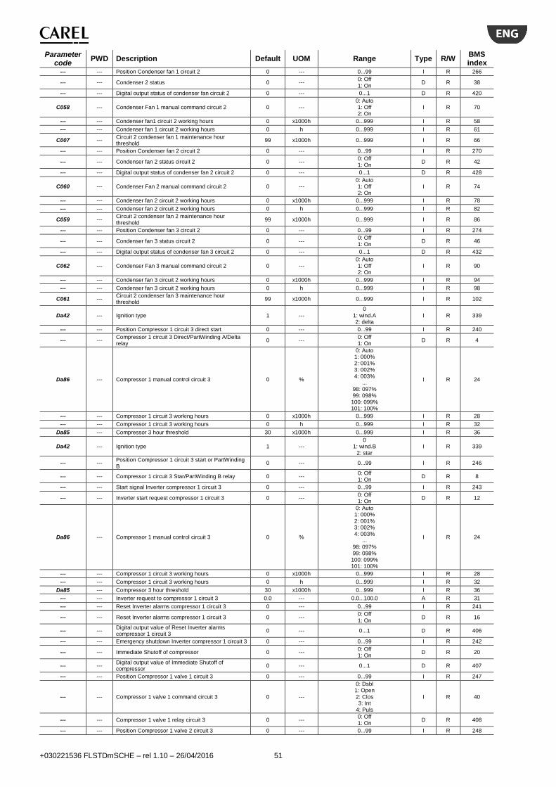
+030221536 FLSTDmSCHE – rel 1.10 – 26/04/2016 51
Parameter code
PWD Description Default UOM Range Type R/W BMS index
--- --- Position Condenser fan 1 circuit 2 0 --- 0...99 I R 266
--- --- Condenser 2 status 0 --- 0: Off 1: On
D R 38
--- --- Digital output status of condenser fan circuit 2 0 --- 0...1 D R 420
C058 --- Condenser Fan 1 manual command circuit 2 0 --- 0: Auto 1: Off 2: On
I R 70
--- --- Condenser fan1 circuit 2 working hours 0 x1000h 0...999 I R 58
--- --- Condenser fan 1 circuit 2 working hours 0 h 0...999 I R 61
C007 --- Circuit 2 condenser fan 1 maintenance hour threshold
99 x1000h 0...999 I R 66
--- --- Position Condenser fan 2 circuit 2 0 --- 0...99 I R 270
--- --- Condenser fan 2 status circuit 2 0 --- 0: Off 1: On
D R 42
--- --- Digital output status of condenser fan 2 circuit 2 0 --- 0...1 D R 428
C060 --- Condenser Fan 2 manual command circuit 2 0 --- 0: Auto 1: Off 2: On
I R 74
--- --- Condenser fan 2 circuit 2 working hours 0 x1000h 0...999 I R 78
--- --- Condenser fan 2 circuit 2 working hours 0 h 0...999 I R 82
C059 --- Circuit 2 condenser fan 2 maintenance hour threshold
99 x1000h 0...999 I R 86
--- --- Position Condenser fan 3 circuit 2 0 --- 0...99 I R 274
--- --- Condenser fan 3 status circuit 2 0 --- 0: Off 1: On
D R 46
--- --- Digital output status of condenser fan 3 circuit 2 0 --- 0...1 D R 432
C062 --- Condenser Fan 3 manual command circuit 2 0 --- 0: Auto 1: Off 2: On
I R 90
--- --- Condenser fan 3 circuit 2 working hours 0 x1000h 0...999 I R 94
--- --- Condenser fan 3 circuit 2 working hours 0 h 0...999 I R 98
C061 --- Circuit 2 condenser fan 3 maintenance hour threshold
99 x1000h 0...999 I R 102
Da42 --- Ignition type 1 --- 0
1: wind.A 2: delta
I R 339
--- --- Position Compressor 1 circuit 3 direct start 0 --- 0...99 I R 240
--- --- Compressor 1 circuit 3 Direct/PartWinding A/Delta relay
0 --- 0: Off 1: On
D R 4
Da86 --- Compressor 1 manual control circuit 3 0 %
0: Auto 1: 000% 2: 001% 3: 002% 4: 003%
... 98: 097% 99: 098%
100: 099% 101: 100%
I R 24
--- --- Compressor 1 circuit 3 working hours 0 x1000h 0...999 I R 28
--- --- Compressor 1 circuit 3 working hours 0 h 0...999 I R 32
Da85 --- Compressor 3 hour threshold 30 x1000h 0...999 I R 36
Da42 --- Ignition type 1 --- 0
1: wind.B 2: star
I R 339
--- --- Position Compressor 1 circuit 3 start or PartWinding B
0 --- 0...99 I R 246
--- --- Compressor 1 circuit 3 Star/PartWinding B relay 0 --- 0: Off 1: On
D R 8
--- --- Start signal Inverter compressor 1 circuit 3 0 --- 0...99 I R 243
--- --- Inverter start request compressor 1 circuit 3 0 --- 0: Off 1: On
D R 12
Da86 --- Compressor 1 manual control circuit 3 0 %
0: Auto 1: 000% 2: 001% 3: 002% 4: 003%
... 98: 097% 99: 098%
100: 099% 101: 100%
I R 24
--- --- Compressor 1 circuit 3 working hours 0 x1000h 0...999 I R 28
--- --- Compressor 1 circuit 3 working hours 0 h 0...999 I R 32
Da85 --- Compressor 3 hour threshold 30 x1000h 0...999 I R 36
--- --- Inverter request to compressor 1 circuit 3 0.0 --- 0.0...100.0 A R 31
--- --- Reset Inverter alarms compressor 1 circuit 3 0 --- 0...99 I R 241
--- --- Reset Inverter alarms compressor 1 circuit 3 0 --- 0: Off 1: On
D R 16
--- --- Digital output value of Reset Inverter alarms compressor 1 circuit 3
0 --- 0...1 D R 406
--- --- Emergency shutdown Inverter compressor 1 circuit 3 0 --- 0...99 I R 242
--- --- Immediate Shutoff of compressor 0 --- 0: Off 1: On
D R 20
--- --- Digital output value of Immediate Shutoff of compressor
0 --- 0...1 D R 407
--- --- Position Compressor 1 valve 1 circuit 3 0 --- 0...99 I R 247
--- --- Compressor 1 valve 1 command circuit 3 0 ---
0: Dsbl 1: Open 2: Clos 3: Int
4: Puls
I R 40
--- --- Compressor 1 valve 1 relay circuit 3 0 --- 0: Off 1: On
D R 408
--- --- Position Compressor 1 valve 2 circuit 3 0 --- 0...99 I R 248
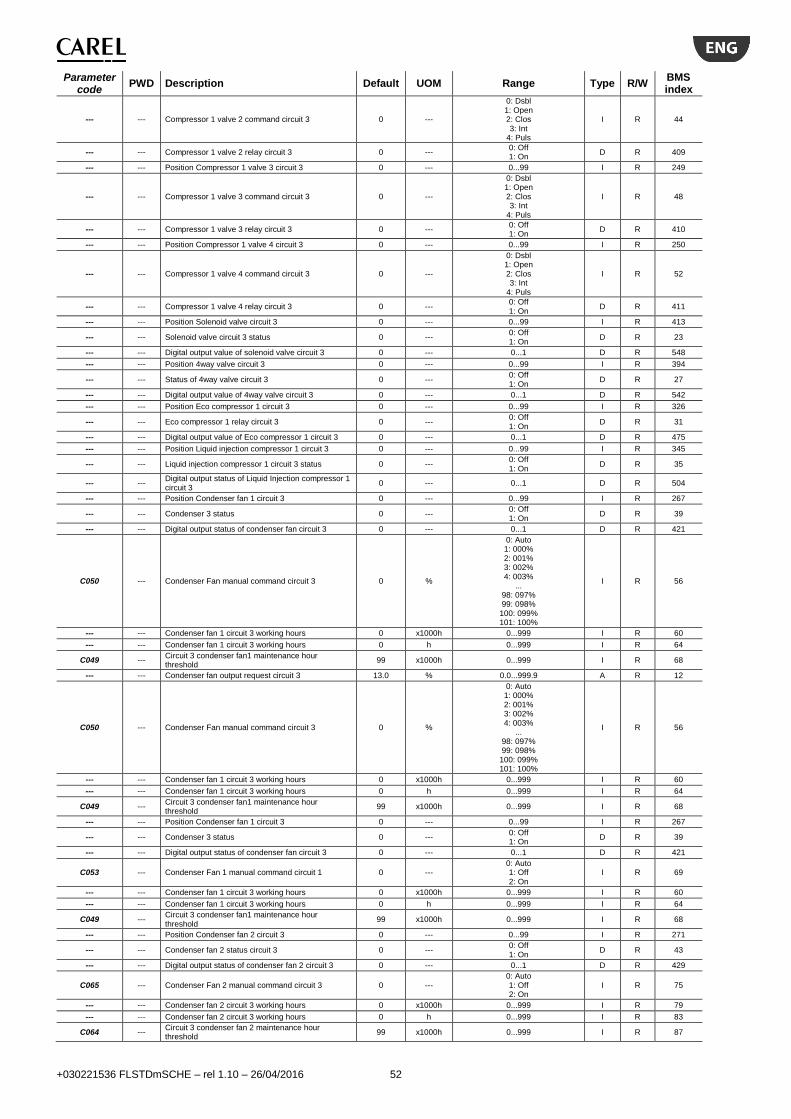
+030221536 FLSTDmSCHE – rel 1.10 – 26/04/2016 52
Parameter code
PWD Description Default UOM Range Type R/W BMS index
--- --- Compressor 1 valve 2 command circuit 3 0 ---
0: Dsbl 1: Open 2: Clos 3: Int
4: Puls
I R 44
--- --- Compressor 1 valve 2 relay circuit 3 0 --- 0: Off 1: On
D R 409
--- --- Position Compressor 1 valve 3 circuit 3 0 --- 0...99 I R 249
--- --- Compressor 1 valve 3 command circuit 3 0 ---
0: Dsbl 1: Open 2: Clos 3: Int
4: Puls
I R 48
--- --- Compressor 1 valve 3 relay circuit 3 0 --- 0: Off 1: On
D R 410
--- --- Position Compressor 1 valve 4 circuit 3 0 --- 0...99 I R 250
--- --- Compressor 1 valve 4 command circuit 3 0 ---
0: Dsbl 1: Open 2: Clos 3: Int
4: Puls
I R 52
--- --- Compressor 1 valve 4 relay circuit 3 0 --- 0: Off 1: On
D R 411
--- --- Position Solenoid valve circuit 3 0 --- 0...99 I R 413
--- --- Solenoid valve circuit 3 status 0 --- 0: Off 1: On
D R 23
--- --- Digital output value of solenoid valve circuit 3 0 --- 0...1 D R 548
--- --- Position 4way valve circuit 3 0 --- 0...99 I R 394
--- --- Status of 4way valve circuit 3 0 --- 0: Off 1: On
D R 27
--- --- Digital output value of 4way valve circuit 3 0 --- 0...1 D R 542
--- --- Position Eco compressor 1 circuit 3 0 --- 0...99 I R 326
--- --- Eco compressor 1 relay circuit 3 0 --- 0: Off 1: On
D R 31
--- --- Digital output value of Eco compressor 1 circuit 3 0 --- 0...1 D R 475
--- --- Position Liquid injection compressor 1 circuit 3 0 --- 0...99 I R 345
--- --- Liquid injection compressor 1 circuit 3 status 0 --- 0: Off 1: On
D R 35
--- --- Digital output status of Liquid Injection compressor 1 circuit 3
0 --- 0...1 D R 504
--- --- Position Condenser fan 1 circuit 3 0 --- 0...99 I R 267
--- --- Condenser 3 status 0 --- 0: Off 1: On
D R 39
--- --- Digital output status of condenser fan circuit 3 0 --- 0...1 D R 421
C050 --- Condenser Fan manual command circuit 3 0 %
0: Auto 1: 000% 2: 001% 3: 002% 4: 003%
... 98: 097% 99: 098%
100: 099% 101: 100%
I R 56
--- --- Condenser fan 1 circuit 3 working hours 0 x1000h 0...999 I R 60
--- --- Condenser fan 1 circuit 3 working hours 0 h 0...999 I R 64
C049 --- Circuit 3 condenser fan1 maintenance hour threshold
99 x1000h 0...999 I R 68
--- --- Condenser fan output request circuit 3 13.0 % 0.0...999.9 A R 12
C050 --- Condenser Fan manual command circuit 3 0 %
0: Auto 1: 000% 2: 001% 3: 002% 4: 003%
... 98: 097% 99: 098%
100: 099% 101: 100%
I R 56
--- --- Condenser fan 1 circuit 3 working hours 0 x1000h 0...999 I R 60
--- --- Condenser fan 1 circuit 3 working hours 0 h 0...999 I R 64
C049 --- Circuit 3 condenser fan1 maintenance hour threshold
99 x1000h 0...999 I R 68
--- --- Position Condenser fan 1 circuit 3 0 --- 0...99 I R 267
--- --- Condenser 3 status 0 --- 0: Off 1: On
D R 39
--- --- Digital output status of condenser fan circuit 3 0 --- 0...1 D R 421
C053 --- Condenser Fan 1 manual command circuit 1 0 --- 0: Auto 1: Off 2: On
I R 69
--- --- Condenser fan 1 circuit 3 working hours 0 x1000h 0...999 I R 60
--- --- Condenser fan 1 circuit 3 working hours 0 h 0...999 I R 64
C049 --- Circuit 3 condenser fan1 maintenance hour threshold
99 x1000h 0...999 I R 68
--- --- Position Condenser fan 2 circuit 3 0 --- 0...99 I R 271
--- --- Condenser fan 2 status circuit 3 0 --- 0: Off 1: On
D R 43
--- --- Digital output status of condenser fan 2 circuit 3 0 --- 0...1 D R 429
C065 --- Condenser Fan 2 manual command circuit 3 0 --- 0: Auto 1: Off 2: On
I R 75
--- --- Condenser fan 2 circuit 3 working hours 0 x1000h 0...999 I R 79
--- --- Condenser fan 2 circuit 3 working hours 0 h 0...999 I R 83
C064 --- Circuit 3 condenser fan 2 maintenance hour threshold
99 x1000h 0...999 I R 87
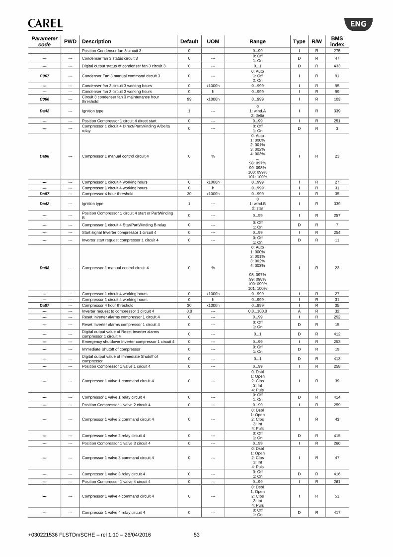
+030221536 FLSTDmSCHE – rel 1.10 – 26/04/2016 53
Parameter code
PWD Description Default UOM Range Type R/W BMS index
--- --- Position Condenser fan 3 circuit 3 0 --- 0...99 I R 275
--- --- Condenser fan 3 status circuit 3 0 --- 0: Off 1: On
D R 47
--- --- Digital output status of condenser fan 3 circuit 3 0 --- 0...1 D R 433
C067 --- Condenser Fan 3 manual command circuit 3 0 --- 0: Auto 1: Off 2: On
I R 91
--- --- Condenser fan 3 circuit 3 working hours 0 x1000h 0...999 I R 95
--- --- Condenser fan 3 circuit 3 working hours 0 h 0...999 I R 99
C066 --- Circuit 3 condenser fan 3 maintenance hour threshold
99 x1000h 0...999 I R 103
Da42 --- Ignition type 1 --- 0
1: wind.A 2: delta
I R 339
--- --- Position Compressor 1 circuit 4 direct start 0 --- 0...99 I R 251
--- --- Compressor 1 circuit 4 Direct/PartWinding A/Delta relay
0 --- 0: Off 1: On
D R 3
Da88 --- Compressor 1 manual control circuit 4 0 %
0: Auto 1: 000% 2: 001% 3: 002% 4: 003%
... 98: 097% 99: 098%
100: 099% 101: 100%
I R 23
--- --- Compressor 1 circuit 4 working hours 0 x1000h 0...999 I R 27
--- --- Compressor 1 circuit 4 working hours 0 h 0...999 I R 31
Da87 --- Compressor 4 hour threshold 30 x1000h 0...999 I R 35
Da42 --- Ignition type 1 --- 0
1: wind.B 2: star
I R 339
--- --- Position Compressor 1 circuit 4 start or PartWinding B
0 --- 0...99 I R 257
--- --- Compressor 1 circuit 4 Star/PartWinding B relay 0 --- 0: Off 1: On
D R 7
--- --- Start signal Inverter compressor 1 circuit 4 0 --- 0...99 I R 254
--- --- Inverter start request compressor 1 circuit 4 0 --- 0: Off 1: On
D R 11
Da88 --- Compressor 1 manual control circuit 4 0 %
0: Auto 1: 000% 2: 001% 3: 002% 4: 003%
... 98: 097% 99: 098%
100: 099% 101: 100%
I R 23
--- --- Compressor 1 circuit 4 working hours 0 x1000h 0...999 I R 27
--- --- Compressor 1 circuit 4 working hours 0 h 0...999 I R 31
Da87 --- Compressor 4 hour threshold 30 x1000h 0...999 I R 35
--- --- Inverter request to compressor 1 circuit 4 0.0 --- 0.0...100.0 A R 32
--- --- Reset Inverter alarms compressor 1 circuit 4 0 --- 0...99 I R 252
--- --- Reset Inverter alarms compressor 1 circuit 4 0 --- 0: Off 1: On
D R 15
--- --- Digital output value of Reset Inverter alarms compressor 1 circuit 4
0 --- 0...1 D R 412
--- --- Emergency shutdown Inverter compressor 1 circuit 4 0 --- 0...99 I R 253
--- --- Immediate Shutoff of compressor 0 --- 0: Off 1: On
D R 19
--- --- Digital output value of Immediate Shutoff of compressor
0 --- 0...1 D R 413
--- --- Position Compressor 1 valve 1 circuit 4 0 --- 0...99 I R 258
--- --- Compressor 1 valve 1 command circuit 4 0 ---
0: Dsbl 1: Open 2: Clos 3: Int
4: Puls
I R 39
--- --- Compressor 1 valve 1 relay circuit 4 0 --- 0: Off 1: On
D R 414
--- --- Position Compressor 1 valve 2 circuit 4 0 --- 0...99 I R 259
--- --- Compressor 1 valve 2 command circuit 4 0 ---
0: Dsbl 1: Open 2: Clos 3: Int
4: Puls
I R 43
--- --- Compressor 1 valve 2 relay circuit 4 0 --- 0: Off 1: On
D R 415
--- --- Position Compressor 1 valve 3 circuit 4 0 --- 0...99 I R 260
--- --- Compressor 1 valve 3 command circuit 4 0 ---
0: Dsbl 1: Open 2: Clos 3: Int
4: Puls
I R 47
--- --- Compressor 1 valve 3 relay circuit 4 0 --- 0: Off 1: On
D R 416
--- --- Position Compressor 1 valve 4 circuit 4 0 --- 0...99 I R 261
--- --- Compressor 1 valve 4 command circuit 4 0 ---
0: Dsbl 1: Open 2: Clos 3: Int
4: Puls
I R 51
--- --- Compressor 1 valve 4 relay circuit 4 0 --- 0: Off 1: On
D R 417

+030221536 FLSTDmSCHE – rel 1.10 – 26/04/2016 54
Parameter code
PWD Description Default UOM Range Type R/W BMS index
--- --- Position Solenoid valve circuit 4 0 --- 0...99 I R 414
--- --- Solenoid valve circuit 4 status 0 --- 0: Off 1: On
D R 24
--- --- Digital output value of solenoid valve circuit 4 0 --- 0...1 D R 549
--- --- Position 4way valve circuit 4 0 --- 0...99 I R 395
--- --- Status of 4way valve circuit 4 0 --- 0: Off 1: On
D R 28
--- --- Digital output value of 4way valve circuit 4 0 --- 0...1 D R 543
--- --- Position Eco compressor 1 circuit 4 0 --- 0...99 I R 327
--- --- Eco compressor 1 relay circuit 4 0 --- 0: Off 1: On
D R 32
--- --- Digital output value of Eco compressor 1 circuit 4 0 --- 0...1 D R 476
--- --- Position Liquid injection compressor 1 circuit 4 0 --- 0...99 I R 346
--- --- Liquid injection compressor 1 circuit 4 status 0 --- 0: Off 1: On
D R 36
--- --- Digital output status of Liquid Injection compressor 1 circuit 4
0 --- 0...1 D R 505
--- --- Position Condenser fan 1 circuit 4 0 --- 0...99 I R 268
--- --- Condenser 4 status 0 --- 0: Off 1: On
D R 40
--- --- Digital output status of condenser fan circuit 4 0 --- 0...1 D R 422
C052 --- Condenser Fan manual command circuit 4 0 %
0: Auto 1: 000% 2: 001% 3: 002% 4: 003%
... 98: 097% 99: 098%
100: 099% 101: 100%
I R 55
--- --- Condenser fan 1 circuit 4 working hours 0 x1000h 0...999 I R 59
--- --- Condenser fan 1 circuit 4 working hours 0 h 0...999 I R 63
C051 --- Circuit 4 condenser fan 1 maintenance hour threshold
99 x1000h 0...999 I R 67
--- --- Condenser fan output request circuit 4 13.0 % 0.0...999.9 A R 11
C052 --- Condenser Fan manual command circuit 4 0 %
0: Auto 1: 000% 2: 001% 3: 002% 4: 003%
... 98: 097% 99: 098%
100: 099% 101: 100%
I R 55
--- --- Condenser fan 1 circuit 4 working hours 0 x1000h 0...999 I R 59
--- --- Condenser fan 1 circuit 4 working hours 0 h 0...999 I R 63
C051 --- Circuit 4 condenser fan 1 maintenance hour threshold
99 x1000h 0...999 I R 67
--- --- Position Condenser fan 1 circuit 4 0 --- 0...99 I R 268
--- --- Condenser 4 status 0 --- 0: Off 1: On
D R 40
--- --- Digital output status of condenser fan circuit 4 0 --- 0...1 D R 422
C053 --- Condenser Fan 1 manual command circuit 1 0 --- 0: Auto 1: Off 2: On
I R 69
--- --- Condenser fan 1 circuit 4 working hours 0 x1000h 0...999 I R 59
--- --- Condenser fan 1 circuit 4 working hours 0 h 0...999 I R 63
C051 --- Circuit 4 condenser fan 1 maintenance hour threshold
99 x1000h 0...999 I R 67
--- --- Position Condenser fan 2 circuit 4 0 --- 0...99 I R 272
--- --- Condenser fan 2 status circuit 4 0 --- 0: Off 1: On
D R 44
--- --- Digital output status of condenser fan 2 circuit 4 0 --- 0...1 D R 430
C070 --- Condenser Fan 2 manual command circuit 4 0 --- 0: Auto 1: Off 2: On
I R 76
--- --- Condenser fan 2 circuit 4 working hours 0 x1000h 0...999 I R 80
--- --- Condenser fan 2 circuit 4 working hours 0 h 0...999 I R 84
C069 --- Circuit 4 condenser fan 2 maintenance hour threshold
99 x1000h 0...999 I R 88
--- --- Position Condenser fan 3 circuit 4 0 --- 0...99 I R 276
--- --- Condenser fan 3 status circuit 4 0 --- 0: Off 1: On
D R 48
--- --- Digital output status of condenser fan 3 circuit 4 0 --- 0...1 D R 434
C072 --- Condenser Fan 3 manual command circuit 4 0 --- 0: Auto 1: Off 2: On
I R 92
--- --- Condenser fan 3 circuit 4 working hours 0 x1000h 0...999 I R 96
--- --- Condenser fan 3 circuit 4 working hours 0 h 0...999 I R 100
C071 --- Circuit 4 condenser fan 3 maintenance hour threshold
99 x1000h 0...999 I R 104
--- --- Position Digital output value of evaporator pump 1 0 --- 0...99 I R 328
--- --- Evaporator pump 1 status 0 --- 0: Off 1: On
D R 49
--- --- Digital output status of evaporator pump 1 0 --- 0...1 D R 487
A002 --- Evaporator pump in manual mode 0 --- 0: Auto 1: Off 2: On
I R 105
--- --- Evaporator pump 1 working hours 0 x1000h 0...999 I R 106
--- --- Evaporator pump 1 working hours 0 h 0...999 I R 107
A001 --- Evaporator pump 1 maintenance hour threshold 99 x1000h 0...999 I R 108

+030221536 FLSTDmSCHE – rel 1.10 – 26/04/2016 55
Parameter code
PWD Description Default UOM Range Type R/W BMS index
--- --- Position Digital output value of evaporator pump 2 0 --- 0...99 I R 329
--- --- Evaporator pump 2 status 0 --- 0: Off 1: On
D R 50
--- --- Digital output status of evaporator pump 2 0 --- 0...1 D R 488
A002 --- Evaporator pump in manual mode 0 --- 0: Auto 1: Off 2: On
I R 105
--- --- Evaporator pump 2 working hours 0 x1000h 0...999 I R 109
--- --- Evaporator pump 2 working hours 0 h 0...999 I R 110
A003 --- Evaporator pump 2 maintenance hour threshold 99 x1000h 0...999 I R 111
--- --- Evaporator pump 2 status 0 --- 0: 0.0
1: 100.0 D R 50
A002 --- Evaporator pump in manual mode 0 --- 0: Auto 1: Off 2: On
I R 105
--- --- Evaporator pump 2 working hours 0 x1000h 0...999 I R 109
--- --- Evaporator pump 2 working hours 0 h 0...999 I R 110
A003 --- Evaporator pump 2 maintenance hour threshold 99 x1000h 0...999 I R 111
--- --- Position Condenser fan 1 circuit 1 0 --- 0...99 I R 265
--- --- Condenser 1 status 0 --- 0: Off 1: On
D R 37
--- --- Digital output status of condenser fan circuit 1 0 --- 0...1 D R 419
C002 --- Condenser pump in manual mode 0 --- 0: Auto 1: Off 2: On
I R 112
--- --- Condenser pump 1 working hours 0 x1000h 0...999 I R 113
--- --- Condenser pump 1 working hours 0 h 0...999 I R 114
C001 --- Condenser pump 1 maintenance hour threshold 99 x1000h 0...999 I R 115
--- --- Position Condenser fan 1 circuit 2 0 --- 0...99 I R 266
--- --- Condenser 2 status 0 --- 0: Off 1: On
D R 38
--- --- Digital output status of condenser fan circuit 1 0 --- 0...1 D R 419
C002 --- Condenser pump in manual mode 0 --- 0: Auto 1: Off 2: On
I R 112
--- --- Condenser pump 2 working hours 0 x1000h 0...999 I R 116
--- --- Condenser pump 2 working hours 0 h 0...999 I R 117
C003 --- Condenser pump 2 maintenance hour threshold 99 x1000h 0...999 I R 118
--- --- Antifreeze heater output channel 0 --- 0...99 I R 210
--- --- Antifreeze heater relay 0 --- 0: Off 1: On
D R 51
--- --- Digital output status of antifreeze heater 0 --- 0...1 D R 208
--- --- Position Free cooling 0 --- 0...99 I R
--- --- Free cooling valve status 0 --- 0: Off 1: On
D R 52
--- --- Digital output status of Free cooling valve 0 --- 0...1 D R
--- --- Free cooling valve status 0 --- 0: 0.0
1: 100.0 D R 52
--- --- Position General alarm 0 --- 0...99 I R 338
--- --- General alarm 0 --- 0: Off 1: On
D R 53
--- --- Digital output status of general alarm 0 --- 0...1 D R 494
--- --- Suction pressure circuit 1 0.0 barg/psig -999.9...999.9 A R 33
--- --- Evaporation temperature circuit 1 0.0 °C/°F -999.9...999.9 A R 37
--- --- Suction temperature circuit 1 0.0 °C/°F -999.9...999.9 A R 41
--- --- Discharge pressure circuit 1 0.0 barg/psig -999.9...999.9 A R 45
--- --- Condensing temperature circuit 1 0.0 °C/°F -999.9...999.9 A R 49
--- --- Discharge temperature circuit 1 0.0 °C/°F -999.9...999.9 A R 53
--- --- Suction pressure circuit 2 0.0 barg/psig -999.9...999.9 A R 34
--- --- Evaporation temperature circuit 2 0.0 °C/°F -999.9...999.9 A R 38
--- --- Suction temperature circuit 2 0.0 °C/°F -999.9...999.9 A R 42
--- --- Discharge pressure circuit 2 0.0 barg/psig -999.9...999.9 A R 46
--- --- Condensing temperature circuit 2 0.0 °C/°F -999.9...999.9 A R 50
--- --- Discharge temperature circuit 2 0.0 °C/°F -999.9...999.9 A R 54
--- --- Suction pressure circuit 3 0.0 barg/psig -999.9...999.9 A R 36
--- --- Evaporation temperature circuit 3 0.0 °C/°F -999.9...999.9 A R 40
--- --- Suction temperature circuit 3 0.0 °C/°F -999.9...999.9 A R 44
--- --- Discharge pressure circuit 3 0.0 barg/psig -999.9...999.9 A R 48
--- --- Condensing temperature circuit 3 0.0 °C/°F -999.9...999.9 A R 52
--- --- Discharge temperature circuit 3 0.0 °C/°F -999.9...999.9 A R 56
--- --- Suction pressure circuit 4 0.0 barg/psig -999.9...999.9 A R 35
--- --- Evaporation temperature circuit 4 0.0 °C/°F -999.9...999.9 A R 39
--- --- Suction temperature circuit 4 0.0 °C/°F -999.9...999.9 A R 43
--- --- Discharge pressure circuit 4 0.0 barg/psig -999.9...999.9 A R 47
--- --- Condensing temperature circuit 4 0.0 °C/°F -999.9...999.9 A R 51
--- --- Discharge temperature circuit 4 0.0 °C/°F -999.9...999.9 A R 55
--- --- Inlet water temperature 0.0 °C/°F 0.0...99.9 A R 26
--- --- Outlet water temperature 0.0 °C/°F -999.9...999.9 A R 25
--- --- External temperature 0.0 °C/°F -999.9...999.9 A R 57
--- --- External temperature 0.0 °C/°F -999.9...999.9 A R 57
--- --- Current compressor 1 circuit 1 0.0 A -999.9...999.9 A R 61
--- --- Current compressor 1 circuit 2 0.0 A -999.9...999.9 A R 62
--- --- Current compressor 1 circuit 3 0.0 A -999.9...999.9 A R 64
--- --- Current compressor 1 circuit 4 0.0 A -999.9...999.9 A R 63
--- Compensation setpoint 0.0 % -999.9…999.9 A R 178
--- --- Low pressure switch circuit 1 status 0 --- 0: Ok
1: Alarm D R 54

+030221536 FLSTDmSCHE – rel 1.10 – 26/04/2016 56
Parameter code
PWD Description Default UOM Range Type R/W BMS index
--- --- Digital input 6 status 0 --- 0...1 D R 465
--- --- Oil level circuit 1 0 --- 0: Ok
1: Alarm D R 58
--- --- Digital input 7 status 0 --- 0...1 D R 467
--- --- High pressure switch status circuit 1 0 --- 0: Ok
1: Alarm D R 62
--- --- EVD digital input 1 circuit 1 0 --- 0...1 D R 442
--- --- Overload of compressor 1 circuit 1 0 --- 0: Ok
1: Alarm D R 66
--- --- EVD digital input 2 circuit 1 0 --- 0...1 D R 456
--- --- Inverter RUN feedback compressor 1 circuit 1 0 --- 0: Stop 1: Run
D R 70
--- --- Digital input 13 status 0 --- 0...1 D R 453
--- --- Inverter alarm signal compressor 1 circuit 1 0 --- 0: Ok
1: Alarm D R 74
--- --- EVD digital input 2 circuit 1 0 --- 0...1 D R 456
--- --- Low pressure switch status circuit 2 0 --- 0: Ok
1: Alarm D R 55
--- --- Digital input 9 status 0 --- 0...1 D R 471
--- --- Oil level circuit 2 0 --- 0: Ok
1: Alarm D R 59
--- --- Digital input 10 status 0 --- 0...1 D R 448
--- --- High pressure switch status circuit 2 0 --- 0: Ok
1: Alarm D R 63
--- --- EVD digital input 1 circuit 2 0 --- 0...1 D R 443
--- --- Overload of compressor 1 circuit 2 0 --- 0: Ok
1: Alarm D R 67
--- --- EVD digital input 2 circuit 2 0 --- 0...1 D R 457
--- --- Inverter RUN feedback compressor 1 circuit 2 0 --- 0: Stop 1: Run
D R 71
--- --- Digital input 14 status 0 --- 0...1 D R 455
--- --- Inverter alarm signal compressor 1 circuit 2 0 --- 0: Ok
1: Alarm D R 75
--- --- EVD digital input 2 circuit 2 0 --- 0...1 D R 457
--- --- Low pressure switch circuit 3 status 0 --- 0: Ok
1: Alarm D R 57
--- --- Digital input 6 status on Slave board 0 --- 0...1 D R 464
--- --- Oil level circuit 3 0 --- 0: Ok
1: Alarm D R 61
--- --- Digital input 7 status on Slave board 0 --- 0...1 D R 466
--- --- High pressure switch status circuit 3 0 --- 0: Ok
1: Alarm D R 65
--- --- EVD digital input 1 circuit 3 0 --- 0...1 D R 444
--- --- Overload of compressor 1 circuit 3 0 --- 0: Ok
1: Alarm D R 69
--- --- EVD digital input 2 circuit 3 0 --- 0...1 D R 458
--- --- Inverter RUN feedback compressor 1 circuit 3 0 --- 0: Stop 1: Run
D R 72
--- --- Digital input 13 status on Slave board 0 --- 0...1 D R 452
--- --- Inverter alarm signal compressor 1 circuit 3 0 --- 0: Ok
1: Alarm D R 76
--- --- EVD digital input 2 circuit 3 0 --- 0...1 D R 458
--- --- Low pressure switch circuit 4 status 0 --- 0: Ok
1: Alarm D R 56
--- --- Digital input 9 status on Slave board 0 --- 0...1 D R 470
--- --- Oil level circuit 4 0 --- 0: Ok
1: Alarm D R 60
--- --- Digital input 10 status on Slave board 0 --- 0...1 D R 447
--- --- High pressure switch status circuit 4 0 --- 0: Ok
1: Alarm D R 64
--- --- EVD digital input 1 circuit 4 0 --- 0...1 D R 445
--- --- Overload of compressor 1 circuit 4 0 --- 0: Ok
1: Alarm D R 68
--- --- EVD digital input 2 circuit 4 0 --- 0...1 D R 459
--- --- Inverter RUN feedback compressor 1 circuit 4 0 --- 0: Stop 1: Run
D R 73
--- --- Digital input 14 status on Slave board 0 --- 0...1 D R 454
--- --- Inverter alarm signal compressor 1 circuit 4 0 --- 0: Ok
1: Alarm D R 77
--- --- EVD digital input 2 circuit 4 0 --- 0...1 D R 459
--- --- Evaporator Flow switch status 0 --- 0: Ok
1: Alarm D R 78
--- --- Digital input 4 status 0 --- 0...1 D R 462
--- --- Evaporator pump 1 overload 0 --- 0: Ok
1: Alarm D R 79
--- --- Digital input 12 status 0 --- 0...1 D R 451
--- --- Evaporator pump 2 overload 0 --- 0: Ok
1: Alarm D R 80
--- --- Digital input 13 status 0 --- 0...1 D R 453
--- --- Condenser Flow switch status 0 --- 0: Ok
1: Alarm D R 81
--- --- Digital input 5 status 0 --- 0...1 D R 463
--- --- Condenser 1 overload 0 --- 0: Ok
1: Alarm D R 82
--- --- Digital input 8 status 0 --- 0...1 D R 469
--- --- Condenser 2 overload 0 --- 0: Ok
1: Alarm D R 83
--- --- Digital input 11 status 0 --- 0...1 D R 450
--- --- Condenser 3 overload 0 --- 0: Ok
1: Alarm D R 84
--- --- Digital input 8 status on Slave board 0 --- 0...1 D R 468
--- --- Condenser 4 overload 0 --- 0: Ok
1: Alarm D R 85

+030221536 FLSTDmSCHE – rel 1.10 – 26/04/2016 57
Parameter code
PWD Description Default UOM Range Type R/W BMS index
--- --- Digital input 11 status on Slave board 0 --- 0...1 D R 449
--- --- Remote alarm 0 --- 0: Ok
1: Alarm D R 86
--- --- Digital input 1 status 0 --- 0...1 D R 446
--- --- Summer/Winter selection by digital input 0 --- 0: Cool 1: Heat
D R 87
--- --- Digital input 2 status 0 --- 0...1 D R 460
--- --- Remote ON/OFF 0 --- 0: Off 1: On
D R 88
--- --- Digital input 3 status 0 --- 0...1 D R 461
--- --- Second setpoint 0 --- 0: 1° 1: 2°
D R 181
--- --- Universal channel 7/8 status 0 --- 0…1 D R 179
--- --- EVDEVO Firmware version 0.0 --- 0.0...800.0 A R
--- --- The fw in the EVDEVO connected is not compatible with the module
0 --- 0
1: Unable to connect D R
--- --- The fw in the EVDEVO connected is not compatible with the module
0 --- 0
1: to EVD EVO D R
--- --- EVDEVO Firmware version 0.0 --- 0.0...800.0 A R
--- --- The fw in the EVDEVO connected is not compatible with the module
0 --- 0
1: Unable to connect D R
--- --- The fw in the EVDEVO connected is not compatible with the module
0 --- 0
1: to EVD EVO D R
--- --- EVDEVO Firmware version 0.0 --- 0.0...800.0 A R
--- --- The fw in the EVDEVO connected is not compatible with the module
0 --- 0
1: Unable to connect D R
--- --- The fw in the EVDEVO connected is not compatible with the module
0 --- 0
1: to EVD EVO D R
--- --- EVDEVO Firmware version 0.0 --- 0.0...800.0 A R
--- --- The fw in the EVDEVO connected is not compatible with the module
0 --- 0
1: Unable to connect D R
--- --- The fw in the EVDEVO connected is not compatible with the module
0 --- 0
1: to EVD EVO D R
--- --- Major release 9 --- 1...9 I R
--- --- Minor release 9 --- 0...9 I R
--- --- Progressive number 0 --- 0...999 I R
--- --- Indicates that the application is a BETA (0=Beta; 1=Official)
0 --- 0: B 1: O
D R
--- --- Version of Demo application 0 --- 0...99 I R
--- --- Software day 0 --- 0...99 I R
--- --- Software month 0 --- 0...99 I R
--- --- Software year 0 --- 0...99 I R
--- --- High part of BIOS version numer 0 --- 0...9 I R
--- --- Low part of BIOS release version number 0 --- 0...99 I R
--- --- BIOS day 0 --- 0...99 I R
--- --- BIOS month 0 --- 0...99 I R
--- --- BIOS year 0 --- 0...99 I R
--- --- High part of boot version number 0 --- 0...9 I R
--- --- Low part of boot version number 0 --- 0...99 I R
--- --- Boot day 0 --- 0...99 I R
--- --- Boot month 0 --- 0...99 I R
--- --- Boot year 0 --- 0...99 I R
--- --- Type of pCO controller 0 ---
0: pCO2 1: pCO1 2: pCO2 3: pCOC 4: pCOxs
5: pCO OEM 6: ---
7: pCO3 8: SuperNode
9: --- 10: pCO5
11: pCOCompact 12: pCO5+
I R
--- --- pCO Compact Type A 0 --- 0: Type B 1: Type A
D R
--- --- Type of the controller 0 ---
0: " " 1: " " 2: " " 3: " " 4: " " 5: " " 6: " " 7: " " 8: " " 9: " "
10: Large 11: Medium 12: Small
13: XL N.O. 14: " " 15: " " 16: " "
17: XL N.C.
I R
--- --- Indicates the size of the memory on the bank 0 (KB) 0 --- 0...9999 I R
--- --- Indicates the size of the memory on the bank 1 (KB) 0 --- 0...9999 I R
--- --- Builtin DSP 0 --- 0: None 2: PGD0 3: PGD1
I R
--- --- Cycle X Sec 0.0 --- 0.0...99.9 A R
--- --- Cycle Time 0 --- 0...9999 I R

+030221536 FLSTDmSCHE – rel 1.10 – 26/04/2016 58
7.2 On-Off
Parameter code
PWD Description Default UOM Range Type R/W BMS index
--- U Unit status 0 ---
0 1: Unit ON
2: OFF by alarm 3: OFF change-over
4: OFF BMS 5: OFF scheduler
6: OFF input 7: OFF keyboard
8: OFF change-over 9: OFF_CST1
10: OFF_CST2 11: OFF_CST3 12: OFF_CST4
I R 432
Q001 U Request unit On by keyboard 0 --- 0...1 D R/W
7.3 Set
Parameter code
PWD Description Default UOM Range Type R/W BMS index
Q002 U Cooling setpoint 12.0 °C/°F TempLowSetP_CH_Msk...
TempHiSetP_CH_Msk A R/W 58
Q011 U Second cooling setpoint 14.0 °C/°F TempLowSetP_CH_Msk...
TempHiSetP_CH_Msk A R/W 179
--- U Summer/Winter status 0 --- 0: Cool 1: Heat
D R 441
--- U Actual setpoint 0.0 °C/°F 0.0...999.9 A R 27
Q003 U Heating setpoint 40.0 °C/°F TempLowSetP_HP_Msk...
TempHiSetP_HP_Msk A R/W 59
Q012 U Second heating setpoint 35.0 °C/°F TempLowSetP_CH_Msk...
TempHiSetP_CH_Msk A R/W 180
--- U Summer/Winter status 0 --- 0: Cool 1: Heat
D R 441
--- U Actual setpoint 0.0 °C/°F 0.0...999.9 A R 27
Q004 U Cooling/heating (Summer/winter) by keyboard 0 --- 0: COOLING 1: HEATING
D R/W 91
--- U Summer/Winter status 0 --- 0: Cool 1: Heat
D R 441
--- U Actual setpoint 0.0 °C/°F 0.0...999.9 A R 27
Q005 U Day for BMS 0 --- 1...31 I R/W 124
Q006 U Month for BMS 0 --- 1...12 I R/W 125
Q007 U Year for BMS 0 --- 0...99 I R/W 126
--- U Day of week based on current date 0 ---
0: *** 1: Monday 2: Tuesday
3: Wednesday 4: Thursday
5: Friday 6: Saturday 7: Sunday
I R
Q008 U Clock hour for BMS 0 --- 0...23 I R/W 122
Q009 U Clock minute for BMS 0 --- 0...59 I R/W 123
--- U Current language index (0=first language) 0 --- 0: E 1: I 2: S
I R/W
--- U Day displayed for scheduling 0 ---
0: MON 1: TUE 2: WED 3: THU 4: FRI 5: SAT 6: SUN
I R/W
--- U Day to overwrite for scheduling 0 ---
0: MON 1: TUE 2: WED 3: THU 4: FRI 5: SAT 6: SUN
I R/W
--- U Enable day scheduling copy 0 --- 0: NO 1: YES
D R/W
--- U Current scheduling hour (inf lim) 0 --- 0...23 I R
--- U Enable graphic scheduling 0 --- 0
1: : D R
--- U Current scheduling minute (inf lim) 0 --- 0...23 I R
--- U Enable graphic scheduling 0 --- 0
1: ÷ D R
--- U Current scheduling hour (sup lim) 0 --- 0...23 I R
--- U Enable graphic scheduling 0 --- 0
1: : D R
--- U Current scheduling minute (sup lim) 0 --- 0...23 I R
--- U Data loaded 0 --- 0
1: 00-08: D R
--- U Scheduling 00:00 0 --- 0...Set_Limit I R/W
--- U Scheduling 00:30 0 --- 0...Set_Limit I R/W
--- U Scheduling 01:00 0 --- 0...Set_Limit I R/W
--- U Scheduling 01:30 0 --- 0...Set_Limit I R/W
--- U Scheduling 02:00 0 --- 0...Set_Limit I R/W
--- U Scheduling 02:30 0 --- 0...Set_Limit I R/W
--- U Scheduling 03:00 0 --- 0...Set_Limit I R/W

+030221536 FLSTDmSCHE – rel 1.10 – 26/04/2016 59
Parameter code
PWD Description Default UOM Range Type R/W BMS index
--- U Scheduling 03:30 0 --- 0...Set_Limit I R/W
--- U Scheduling 04:00 0 --- 0...Set_Limit I R/W
--- U Scheduling 04:30 0 --- 0...Set_Limit I R/W
--- U Scheduling 05:00 0 --- 0...Set_Limit I R/W
--- U Scheduling 05:30 0 --- 0...Set_Limit I R/W
--- U Scheduling 06:00 0 --- 0...Set_Limit I R/W
--- U Scheduling 06:30 0 --- 0...Set_Limit I R/W
--- U Scheduling 07:00 0 --- 0...Set_Limit I R/W
--- U Scheduling 07:30 0 --- 0...Set_Limit I R/W
--- U Data loaded 0 --- 0: LOADING...
1: -- D R
--- U Data loaded 0 --- 0
1: 08-16: D R
--- U Scheduling 08:00 0 --- 0...Set_Limit I R/W
--- U Scheduling 08:30 0 --- 0...Set_Limit I R/W
--- U Scheduling 09:00 0 --- 0...Set_Limit I R/W
--- U Scheduling 09:30 0 --- 0...Set_Limit I R/W
--- U Scheduling 10:00 0 --- 0...Set_Limit I R/W
--- U Scheduling 10:30 0 --- 0...Set_Limit I R/W
--- U Scheduling 11:00 0 --- 0...Set_Limit I R/W
--- U Scheduling 11:30 0 --- 0...Set_Limit I R/W
--- U Scheduling 12:00 0 --- 0...Set_Limit I R/W
--- U Scheduling 12:30 0 --- 0...Set_Limit I R/W
--- U Scheduling 13:00 0 --- 0...Set_Limit I R/W
--- U Scheduling 13:30 0 --- 0...Set_Limit I R/W
--- U Scheduling 14:00 0 --- 0...Set_Limit I R/W
--- U Scheduling 14:30 0 --- 0...Set_Limit I R/W
--- U Scheduling 15:00 0 --- 0...Set_Limit I R/W
--- U Scheduling 15:30 0 --- 0...Set_Limit I R/W
--- U Data loaded 0 --- 0
1: 16-24: D R
--- U Scheduling 16:00 0 --- 0...Set_Limit I R/W
--- U Scheduling 16:30 0 --- 0...Set_Limit I R/W
--- U Scheduling 17:00 0 --- 0...Set_Limit I R/W
--- U Scheduling 17:30 0 --- 0...Set_Limit I R/W
--- U Scheduling 18:00 0 --- 0...Set_Limit I R/W
--- U Scheduling 18:30 0 --- 0...Set_Limit I R/W
--- U Scheduling 19:00 0 --- 0...Set_Limit I R/W
--- U Scheduling 19:30 0 --- 0...Set_Limit I R/W
--- U Scheduling 20:00 0 --- 0...Set_Limit I R/W
--- U Scheduling 20:30 0 --- 0...Set_Limit I R/W
--- U Scheduling 21:00 0 --- 0...Set_Limit I R/W
--- U Scheduling 21:30 0 --- 0...Set_Limit I R/W
--- U Scheduling 22:00 0 --- 0...Set_Limit I R/W
--- U Scheduling 22:30 0 --- 0...Set_Limit I R/W
--- U Scheduling 23:00 0 --- 0...Set_Limit I R/W
--- U Scheduling 23:30 0 --- 0...Set_Limit I R/W
7.4 Plant
Parameter code
PWD Description Default UOM Range Type R/W BMS index
--- S Evaporator pump 1 working hours 0 x1000h 0...999 I R 106
--- S Evaporator pump 1 working hours 0 h 0...999 I R 107
A001 S Evaporator pump 1 maintenance hour threshold 99 x1000h 0...999 I R/W 108
--- S Reset hour counters evaporator pump 1 0 --- 0: N 1: Y
D R/W 538
--- S Evaporator pump 1 status 0 --- 0: Off 1: On
D R 49
A002 S Evaporator pump in manual mode 0 --- 0: AUTO 1: OFF 2: ON
I R/W 105
--- S Evaporator pump 2 working hours 0 x1000h 0...999 I R 109
--- S Evaporator pump 2 working hours 0 h 0...999 I R 110
A003 S Evaporator pump 2 maintenance hour threshold 99 x1000h 0...999 I R/W 111
--- S Reset hour counters evaporator pump 2 0 --- 0: N 1: Y
D R/W 539
--- S Evaporator pump 2 status 0 --- 0: Off 1: On
D R 50
A004 S Switch-over evaporator pumps 0 --- 0: N 1: Y
D R/W 552
A005 S Temperature low setpoint limits in chiller 5.0 °C/°F -3276.8...3276.7 A R/W 355
A006 S Temperature high setpoint limits in chiller 20.0 °C/°F -3276.8...3276.7 A R/W 353
A007 S Temperature low setpoint limits in heat pump 30.0 °C/°F -3276.8...3276.7 A R/W 356
A008 S Temperature high setpoint limits in heat pump 45.0 °C/°F -3276.8...3276.7 A R/W 354
A051 S Enable compensation/double setpoint 0 --- 0: NONE
1: COMPENSATION 2: DOUBLE SETPOINT
I R/W 470
A052 S Compensation probe type 1 --- 0…5 I R/W 468
A053 S Cooling minimum compensation setpoint 12.0 °C/°F 0.0..99.9 A R/W 173
A054 S Cooling maximum compensation setpoint 12.0 °C/°F 0.0..99.9 A R/W 174
A055 S Heating minimum compensation setpoint 40.0 °C/°F 0.0..99.9 A R/W 175
A056 S Heating maximum compensation setpoint 50.0 °C/°F 0.0..99.9 A R/W 176
A014 S Tau par. for exponential distribution on temp. 5 s 1...999 I R/W 391
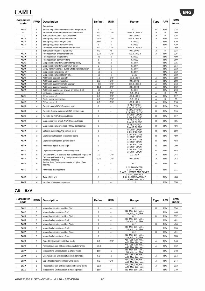
+030221536 FLSTDmSCHE – rel 1.10 – 26/04/2016 60
Parameter code
PWD Description Default UOM Range Type R/W BMS index
Regulation
A058 S Enable regulation on source water temperature 0 --- 0…1 D R/W 178
--- S Reference water temperature to startup PID 0.0 °C/°F -3276.8...3276.7 A R 360
--- S Temperature request by startup PID 0.0 --- 0.0...100.0 A R 325
A015 S Startup regulation proportional band 16.0 °C/°F -999.9...999.9 A R/W 348
A016 S Startup regulation integral time 180 s 0...9999 I R/W 430
A017 S Startup regulation derivative time 0 s 0...9999 I R/W 429
--- S Reference water temperature to run PID 0.0 °C/°F -3276.8...3276.7 A R 359
--- S Temperature request by run PID 0.0 % 0.0...100.0 A R 324
A018 S Run regulation proportional band 10.0 °C/°F -999.9...999.9 A R/W 326
A019 S Run regulation integral time 40 s 0...9999 I R/W 400
A020 S Run regulation derivative time 5 s 0...9999 I R/W 399
A021 S Evaporator pump flow alarm startup delay 20 s 0...999 I R/W 315
A022 S Evaporator pump flow alarm run delay 2 s 0...999 I R/W 314
A023 S Delay from evaporator pump ON to start regulation 60 s 0...999 I R/W 313
A024 S Evaporator pump delay OFF 10 s 0...999 I R/W 312
A025 S Evaporator pumps rotation time 12 h 0...99 I R/W 332
A026 S Antifreeze setpoint (unit off) 4.0 °C/°F -99.9...99.9 A R/W 209
A027 S Antifreeze alarm differential 2.0 °C/°F 0.0...999.9 A R/W 208
A028 S Antifreeze alarm threshold (unit on) -0.8 °C/°F -999.9...999.9 A R/W 213
A029 S Antifreeze alarm differential 30.0 °C/°F 0.0...999.9 A R/W 212
A030 S Antifreeze alarm delay time at 1K below thrsh 60 s 5...300 I R/W 213
--- S Inlet water temperature 0.0 °C/°F 0.0...99.9 A R 26
A031 S Offset probe U1 0.0 °C/°F -99.9...99.9 A R/W 317
--- S Outlet water temperature 0.0 °C/°F 0.0...99.9 A R 25
A032 S Offset probe U2 0.0 °C/°F -99.9...99.9 A R/W 318
A033 M Remote alarm NO/NC contact logic 0 --- 0: AL.IF OPEN 1: AL.IF CLOSE
D R/W 515
A034 M Remote Summer/Winter NO/NC contact logic 0 --- 0: SUM.IF OPEN 1: SUM.IF CLOSE
D R/W 516
A035 M Remote On NO/NC contact logic 1 --- 0: ON IF OPEN 1: ON IF CLOSE
D R/W 517
A036 M Evaporator flow switch NO/NC contact logic 0 --- 0: AL.IF OPEN 1: AL.IF CLOSE
D R/W 485
A037 M Evaporator pump overload NO/NC contact logic 0 --- 0: AL.IF OPEN 1: AL.IF CLOSE
D R/W 486
A059 M Setpoint switch NO/NC contact logic 0 --- 0: ON IF OPEN 1: ON IF CLOSE
D R/W 180
A038 M Digital output logic of evaporator pump 0 --- 0: ON IF CLOSE 1: ON IF OPEN
D R/W 489
A039 M Digital output logic of general alarm 0 --- 0: ON IF CLOSE 1: ON IF OPEN
D R/W 493
A040 M Antifreeze digital output logic 0 --- 0: ON IF CLOSE 1: ON IF OPEN
D R/W 209
A047 M Digital output logic of Free cooling valve 0 --- 0: ON IF CLOSE 1: ON IF OPEN
D R/W 492
A045 M Delta temp FC to activate free-cooling coil regulation 3.0 °C/°F 0.0...99.9 A R/W 244
A046 M Delta temp Free Cooling design (to reach unit nominal capacity)
10.0 °C/°F 0.0...999.9 A R/W 243
A044 M Enable Free Cooling with outdor air (direct free-cooling)
0 --- 0...1 D R/W 481
A041 M Antifreeze management 0 --- 0: WITH HEATER 1: WITH PUMPS
2: WITH HEATER AND PUMPS I R/W 211
A042 M Type of the unit 1 --- 0: CHILLER ONLY
1: CHILLER/HEATPUMP 2: HEATPUMP ONLY
I R/W 433
A043 M Number of evaporator pumps 1 --- 1...2 I R/W 330
7.5 ExV
Parameter code
PWD Description Default UOM Range Type R/W BMS index
B001 S Manual positioning enable - Circ1 0 --- 0...1 D R/W 554
B002 S Manual valve position - Circ1 0 --- I39_Msk_Lim_Min... I39_Msk_Lim_Max
I R/W 448
B003 S Manual positioning enable - Circ2 0 --- 0...1 D R/W 557
B004 S Manual valve position - Circ2 0 --- I39_Msk_Lim_Min... I39_Msk_Lim_Max
I R/W 461
B055 S Manual positioning enable - Circ3 0 --- 0...1 D R/W 490
B056 S Manual valve position - Circ3 0 --- I39_Msk_Lim_Min... I39_Msk_Lim_Max
I R/W 333
B057 S Manual positioning enable - Circ4 0 --- 0...1 D R/W 491
B058 S Manual valve position - Circ4 0 --- I39_Msk_Lim_Min... I39_Msk_Lim_Max
I R/W 335
B005 S SuperHeat setpoint in Chiller mode 8.0 °C/°F A50_Msk_Lim_Min... A50_Msk_Lim_Max
A R/W 343
B006 S Proportional gain SH regulation in chiller mode 15.0 --- A48_Msk_Lim_Min... A48_Msk_Lim_Max
A R/W 312
B007 S Integral time SH regulation in chiller mode 150 s I38_Msk_Lim_Min... I38_Msk_Lim_Max
I R/W 378
B008 S Derivative time SH regulation in chiller mode 5.0 s A49_Msk_Lim_Min... A49_Msk_Lim_Max
A R/W 314
B009 S SuperHeat setpoint in HeatPump mode 8.0 °C/°F A50_Msk_Lim_Min... A50_Msk_Lim_Max
A R/W 344
B010 S Proportional gain SH regulation in heating mode 15.0 --- A48_Msk_Lim_Min... A48_Msk_Lim_Max
A R/W 313
B011 S Integral time SH regulation in heating mode 150 s I38_Msk_Lim_Min... I R/W 379

+030221536 FLSTDmSCHE – rel 1.10 – 26/04/2016 61
Parameter code
PWD Description Default UOM Range Type R/W BMS index
I38_Msk_Lim_Max
B012 S Derivative time SH regulation in heating mode 5.0 s A49_Msk_Lim_Min... A49_Msk_Lim_Max
A R/W 315
B013 S EEV Low SuperHeating threshold in Chiller mode 2.0 °C/°F A56_Msk_Lim_Min... A56_Msk_Lim_Max
A R/W 302
B014 S Integral time Low SH in chiller mode 15.0 s A55_Msk_Lim_Min... A55_Msk_Lim_Max
A R/W 304
B015 S EEV Low SuperHeating threshold in HeatPump mode
2.0 °C/°F A56_Msk_Lim_Min... A56_Msk_Lim_Max
A R/W 303
B016 S Integral time Low SH in heating mode 15.0 s A55_Msk_Lim_Min... A55_Msk_Lim_Max
A R/W 305
B017 S EEV Low evaporating temp. threshold in Chiller mode
-50.0 °C/°F A52_Msk_Lim_Min... A52_Msk_Lim_Max
A R/W 298
B018 S Integral time LOP regulation in chiller mode 15.0 s A92_Msk_Lim_Min... A92_Msk_Lim_Max
A R/W 300
B019 S EEV Low evaporating temp. threshold in HeatPump mode
-50.0 °C/°F A52_Msk_Lim_Min... A52_Msk_Lim_Max
A R/W 299
B020 S Integral time LOP regulation in heating mode 15.0 s A92_Msk_Lim_Min... A92_Msk_Lim_Max
A R/W 301
B021 S EEV High evaporating temp. threshold in Chiller mode
20.0 °C/°F A54_Msk_Lim_Min... A54_Msk_Lim_Max
A R/W 308
B022 S Integral time MOP regulation in chiller mode 20.0 s A94_Msk_Lim_Min... A94_Msk_Lim_Max
A R/W 310
B023 S EEV High evaporating temp. threshold in HeatPump mode
20.0 °C/°F A54_Msk_Lim_Min... A54_Msk_Lim_Max
A R/W 309
B024 S Integral time MOP regulation in heating mode 20.0 s A94_Msk_Lim_Min... A94_Msk_Lim_Max
A R/W 311
B025 S LowSH: low superheat alarm delay 300 --- I43_Msk_Lim_Min... I43_Msk_Lim_Max
I R/W 452
B026 S Low evaporation temperature alarm delay 300 --- I41_Msk_Lim_Min... I41_Msk_Lim_Max
I R/W 450
B027 S MOP: high temperature evaporation alarm delay 600 --- I42_Msk_Lim_Min... I42_Msk_Lim_Max
I R/W 451
B028 S EEV: High condensing temperature threshold 0.0 °C/°F A58_Msk_Lim_Min... A58_Msk_Lim_Max
A R/W 293
B029 S High condensing temperature: integral time 777.7 --- A57_Msk_Lim_Min... A57_Msk_Lim_Max
A R/W 363
B030 S High condensing temperature alarm delay 600 --- I44_Msk_Lim_Min... I44_Msk_Lim_Max
I R/W 453
B031 S EEV: Low suction temperature threshold 0.0 °C/°F A26_Msk_Lim_Min... A26_Msk_Lim_Max
A R/W 306
B032 S Alarm delay low suction temperature 300 --- I9_Msk_Lim_Min... I9_Msk_Lim_Max
I R/W 455
B033 S Startup valve opening % (capacity ratio EVAP / EEV) - Chiller mode
80 % I60_Msk_Lim_Min... I60_Msk_Lim_Max
I R/W 417
B034 S Startup valve opening % (capacity ratio EVAP / EEV) - HeatPump mode
75 % I60_Msk_Lim_Min... I60_Msk_Lim_Max
I R/W 418
B035 S Pumpdown end evaporation temperature threshold -11.0 °C/°F -999.9...999.9 A R/W 316
B036 S Maximum pumpdown time 20 s 0...999 I R/W 380
B037 S Pumpdown type 0 --- 0: AT START 1: AT STOP
2: AT START & STOP I R/W 381
B038 M Enable liquid solenoid valve 1 --- 0...1 D R/W 484
B039 M Pumpdown valve configuration 3 ---
0: NO PUMP-DOWN 1: SOLENOID VALVE ONLY
2: ExV ONLY 3: SOLENOID AND ExV
I R/W 382
B040 M Regulation delay after power-on 6 --- I90_Msk_Lim_Min... I90_Msk_Lim_Max
I R/W 456
B041 M Output relay configuration 2 ---
0: --- 1: DISABLED
2: ALARM RELAY 3: SOLENOID VALVE RELAY 4: VALVE + ALARM RELAY
5: REVERSED ALARM RELAY 6: VALVE POSITION RELAY
I R/W 438
B042 M Digital output logic of solenoid valve 0 --- 0: ON IF CLOSE 1: ON IF OPEN
D R/W 550
B043 M Valve type 1 ---
0: USER DEFINED 1: CAREL EXV 2: ALCO EX4 3: ALCO EX5 4: ALCO EX6 5: ALCO EX7
6: ALCO EX8 330HZ CAREL RECOMMENDED
7: ALCO EX8 500HZ ALCO SPECIFICATION
8: SPORLAN SEI 0.5-11 9: SPORLAN SER 1.5-20
10: SPORLAN SEI 30 11: SPORLAN SEI 50
12: SPORLAN SEH 100 13: SPORLAN SEH 175
14: Danfoss ETS 12.5 - 25B 15: DANFOSS ETS 50B
16: DANFOSS ETS 100B 17: DANFOSS ETS 250 18: DANFOSS ETS 400
19: TWO CAREL ExV CONNECT. TOGETHER
20: SPORLAN SER(I) G, J, K 21: DANFOSS CCM 10-20-30
22: DANFOSS CCM 40
I R/W 439
B044 M Regulation type 1 ---
0: USER DEFINED 1: CENTRALIZED CABINET
COLD ROOM 2: SELF CONTAINED
CABINETCOLD ROOM 3: PERTURBATED CABINET
I R/W 440

+030221536 FLSTDmSCHE – rel 1.10 – 26/04/2016 62
Parameter code
PWD Description Default UOM Range Type R/W BMS index
COLD ROOM 4: SUBCRITICAL CO2
CABINET/COLD ROOM 5: R404A CONDENSER FOR
SUBCRITICAL CO2 6: AC OR CHILLER WITH PLATE
EVAPORATOR 7: AC OR CHILLER WITH SHELL
TUBE EVAPORATOR 8: AC OR CHILLER WITH BATTERY COIL EVAPOR.
9: AC OR CHILLER WITH VAR. COOLING CAPACITY 10: AC OR CHILLER
PERTURBATED UNIT 11: UNAVAILABLE 1 12: UNAVAILABLE 2 13: UNAVAILABLE 3 14: UNAVAILABLE 4 15: UNAVAILABLE 5 16: UNAVAILABLE 6 17: UNAVAILABLE 7
18: AC/CHILLER WITH DIG. SCROLL COMPRESSOR
19: AC/CHILLER WITH BLDC COMPRESSOR
20: SH REGULATION WITH 2 TEMP. PROBES
21: pCO I/O EXPANDER
B045 M EEV minimum steps 50 --- I30_Msk_Lim_Min... I30_Msk_Lim_Max
I R/W 441
B046 M EEV maximum steps 480 --- I31_Msk_Lim_Min... I31_Msk_Lim_Max
I R/W 442
B047 M EEV full close steps 500 --- I36_Msk_Lim_Min... I36_Msk_Lim_Max
I R/W 447
B048 M EEV move rate 50 --- I32_Msk_Lim_Min... I32_Msk_Lim_Max
I R/W 443
B049 M Rate for fast valve closig (in case of power failure) 150 --- I86_Msk_Lim_Min... I86_Msk_Lim_Max
I R/W 454
B050 M EEV move current 450 --- I33_Msk_Lim_Min... I33_Msk_Lim_Max
I R/W 444
B051 M EEV hold current 100 --- I35_Msk_Lim_Min... I35_Msk_Lim_Max
I R/W 446
B052 M EEV duty cycle 30 --- I34_Msk_Lim_Min... I34_Msk_Lim_Max
I R/W 445
B053 M Opening valve position syncronization 1 --- 0...1 D R/W 556
B054 M Closing valve position syncronization 1 --- 0...1 D R/W 555
7.6 Source
Parameter code
PWD Description Default UOM Range Type R/W BMS index
--- S Condenser pump 1 working hours 0 x1000h 0...999 I R 113
--- S Condenser pump 1 working hours 0 h 0...999 I R 114
C001 S Condenser pump 1 maintenance hour threshold 99 x1000h 0...999 I R/W 115
--- S Reset hour counters condenser pump 1 0 --- 0: N 1: Y
D R/W 536
--- S Condenser pump 1 status 0 --- 0: Off 1: On
D R 439
C002 S Condenser pump in manual mode 0 --- 0: AUTO 1: OFF 2: ON
I R/W 112
--- S Condenser pump 2 working hours 0 x1000h 0...999 I R 116
--- S Condenser pump 2 working hours 0 h 0...999 I R 117
C003 S Condenser pump 2 maintenance hour threshold 99 x1000h 0...999 I R/W 118
--- S Reset hour counters condenser pump 2 0 --- 0: N 1: Y
D R/W 537
--- S Condenser pump 2 status 0 --- 0: Off 1: On
D R 440
C004 S Switch-over condenser pumps 0 --- 0: N 1: Y
D R/W 551
--- S Condenser fan 1 circuit 1 working hours 0 x1000h 0...999 I R 57
--- S Condenser fan 1 circuit 1 working hours 0 h 0...999 I R 62
C005 S Circuit 1 condenser fan 1 maintenance hour threshold
99 x1000h 0...999 I R/W 65
--- S Reset hour counters circuit 1 condenser fan 1 0 --- 0: N 1: Y
D R/W 524
--- S Condenser fan 1 output request circuit 1 13.0 % 0.0...999.9 A R 9
C006 S Condenser Fan manual command circuit 1 0 %
0: AUTO 1: 000% 2: 001% 3: 002% 4: 003%
... 98: 097% 99: 098%
100: 099% 101: 100%
I R/W 53
--- S Condenser fan1 circuit 2 working hours 0 x1000h 0...999 I R 58
--- S Condenser fan 1 circuit 2 working hours 0 h 0...999 I R 61
C007 S Circuit 2 condenser fan 1 maintenance hour threshold
99 x1000h 0...999 I R/W 66
--- S Reset hour counters circuit 2 condenser fan 1 0 --- 0: N 1: Y
D R/W 525
--- S Condenser fan output request circuit 2 13.0 % 0.0...999.9 A R 10
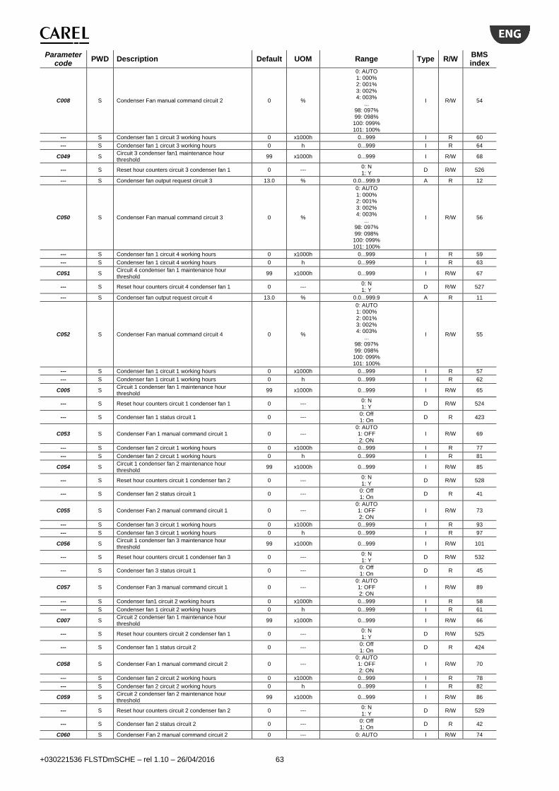
+030221536 FLSTDmSCHE – rel 1.10 – 26/04/2016 63
Parameter code
PWD Description Default UOM Range Type R/W BMS index
C008 S Condenser Fan manual command circuit 2 0 %
0: AUTO 1: 000% 2: 001% 3: 002% 4: 003%
... 98: 097% 99: 098%
100: 099% 101: 100%
I R/W 54
--- S Condenser fan 1 circuit 3 working hours 0 x1000h 0...999 I R 60
--- S Condenser fan 1 circuit 3 working hours 0 h 0...999 I R 64
C049 S Circuit 3 condenser fan1 maintenance hour threshold
99 x1000h 0...999 I R/W 68
--- S Reset hour counters circuit 3 condenser fan 1 0 --- 0: N 1: Y
D R/W 526
--- S Condenser fan output request circuit 3 13.0 % 0.0...999.9 A R 12
C050 S Condenser Fan manual command circuit 3 0 %
0: AUTO 1: 000% 2: 001% 3: 002% 4: 003%
... 98: 097% 99: 098%
100: 099% 101: 100%
I R/W 56
--- S Condenser fan 1 circuit 4 working hours 0 x1000h 0...999 I R 59
--- S Condenser fan 1 circuit 4 working hours 0 h 0...999 I R 63
C051 S Circuit 4 condenser fan 1 maintenance hour threshold
99 x1000h 0...999 I R/W 67
--- S Reset hour counters circuit 4 condenser fan 1 0 --- 0: N 1: Y
D R/W 527
--- S Condenser fan output request circuit 4 13.0 % 0.0...999.9 A R 11
C052 S Condenser Fan manual command circuit 4 0 %
0: AUTO 1: 000% 2: 001% 3: 002% 4: 003%
... 98: 097% 99: 098%
100: 099% 101: 100%
I R/W 55
--- S Condenser fan 1 circuit 1 working hours 0 x1000h 0...999 I R 57
--- S Condenser fan 1 circuit 1 working hours 0 h 0...999 I R 62
C005 S Circuit 1 condenser fan 1 maintenance hour threshold
99 x1000h 0...999 I R/W 65
--- S Reset hour counters circuit 1 condenser fan 1 0 --- 0: N 1: Y
D R/W 524
--- S Condenser fan 1 status circuit 1 0 --- 0: Off 1: On
D R 423
C053 S Condenser Fan 1 manual command circuit 1 0 --- 0: AUTO 1: OFF 2: ON
I R/W 69
--- S Condenser fan 2 circuit 1 working hours 0 x1000h 0...999 I R 77
--- S Condenser fan 2 circuit 1 working hours 0 h 0...999 I R 81
C054 S Circuit 1 condenser fan 2 maintenance hour threshold
99 x1000h 0...999 I R/W 85
--- S Reset hour counters circuit 1 condenser fan 2 0 --- 0: N 1: Y
D R/W 528
--- S Condenser fan 2 status circuit 1 0 --- 0: Off 1: On
D R 41
C055 S Condenser Fan 2 manual command circuit 1 0 --- 0: AUTO 1: OFF 2: ON
I R/W 73
--- S Condenser fan 3 circuit 1 working hours 0 x1000h 0...999 I R 93
--- S Condenser fan 3 circuit 1 working hours 0 h 0...999 I R 97
C056 S Circuit 1 condenser fan 3 maintenance hour threshold
99 x1000h 0...999 I R/W 101
--- S Reset hour counters circuit 1 condenser fan 3 0 --- 0: N 1: Y
D R/W 532
--- S Condenser fan 3 status circuit 1 0 --- 0: Off 1: On
D R 45
C057 S Condenser Fan 3 manual command circuit 1 0 --- 0: AUTO 1: OFF 2: ON
I R/W 89
--- S Condenser fan1 circuit 2 working hours 0 x1000h 0...999 I R 58
--- S Condenser fan 1 circuit 2 working hours 0 h 0...999 I R 61
C007 S Circuit 2 condenser fan 1 maintenance hour threshold
99 x1000h 0...999 I R/W 66
--- S Reset hour counters circuit 2 condenser fan 1 0 --- 0: N 1: Y
D R/W 525
--- S Condenser fan 1 status circuit 2 0 --- 0: Off 1: On
D R 424
C058 S Condenser Fan 1 manual command circuit 2 0 --- 0: AUTO 1: OFF 2: ON
I R/W 70
--- S Condenser fan 2 circuit 2 working hours 0 x1000h 0...999 I R 78
--- S Condenser fan 2 circuit 2 working hours 0 h 0...999 I R 82
C059 S Circuit 2 condenser fan 2 maintenance hour threshold
99 x1000h 0...999 I R/W 86
--- S Reset hour counters circuit 2 condenser fan 2 0 --- 0: N 1: Y
D R/W 529
--- S Condenser fan 2 status circuit 2 0 --- 0: Off 1: On
D R 42
C060 S Condenser Fan 2 manual command circuit 2 0 --- 0: AUTO I R/W 74

+030221536 FLSTDmSCHE – rel 1.10 – 26/04/2016 64
Parameter code
PWD Description Default UOM Range Type R/W BMS index
1: OFF 2: ON
--- S Condenser fan 3 circuit 2 working hours 0 x1000h 0...999 I R 94
--- S Condenser fan 3 circuit 2 working hours 0 h 0...999 I R 98
C061 S Circuit 2 condenser fan 3 maintenance hour threshold
99 x1000h 0...999 I R/W 102
--- S Reset hour counters circuit 2 condenser fan 3 0 --- 0: N 1: Y
D R/W 533
--- S Condenser fan 3 status circuit 2 0 --- 0: Off 1: On
D R 46
C062 S Condenser Fan 3 manual command circuit 2 0 --- 0: AUTO 1: OFF 2: ON
I R/W 90
--- S Condenser fan 1 circuit 3 working hours 0 x1000h 0...999 I R 60
--- S Condenser fan 1 circuit 3 working hours 0 h 0...999 I R 64
C049 S Circuit 3 condenser fan1 maintenance hour threshold
99 x1000h 0...999 I R/W 68
--- S Reset hour counters circuit 3 condenser fan 1 0 --- 0: N 1: Y
D R/W 526
--- S Condenser fan 1 status circuit 3 0 --- 0: Off 1: On
D R 425
C063 S Condenser Fan 1 manual command circuit 3 0 --- 0: AUTO 1: OFF 2: ON
I R/W 71
--- S Condenser fan 2 circuit 3 working hours 0 x1000h 0...999 I R 79
--- S Condenser fan 2 circuit 3 working hours 0 h 0...999 I R 83
C064 S Circuit 3 condenser fan 2 maintenance hour threshold
99 x1000h 0...999 I R/W 87
--- S Reset hour counters circuit 3 condenser fan 2 0 --- 0: N 1: Y
D R/W 530
--- S Condenser fan 2 status circuit 3 0 --- 0: Off 1: On
D R 43
C065 S Condenser Fan 2 manual command circuit 3 0 --- 0: AUTO 1: OFF 2: ON
I R/W 75
--- S Condenser fan 3 circuit 3 working hours 0 x1000h 0...999 I R 95
--- S Condenser fan 3 circuit 3 working hours 0 h 0...999 I R 99
C066 S Circuit 3 condenser fan 3 maintenance hour threshold
99 x1000h 0...999 I R/W 103
--- S Reset hour counters circuit 3 condenser fan 3 0 --- 0: N 1: Y
D R/W 534
--- S Condenser fan 3 status circuit 3 0 --- 0: Off 1: On
D R 47
C067 S Condenser Fan 3 manual command circuit 3 0 --- 0: AUTO 1: OFF 2: ON
I R/W 91
--- S Condenser fan 1 circuit 4 working hours 0 x1000h 0...999 I R 59
--- S Condenser fan 1 circuit 4 working hours 0 h 0...999 I R 63
C051 S Circuit 4 condenser fan 1 maintenance hour threshold
99 x1000h 0...999 I R/W 67
--- S Reset hour counters circuit 4 condenser fan 1 0 --- 0: N 1: Y
D R/W 527
--- S Condenser fan 1 status circuit 4 0 --- 0: Off 1: On
D R 426
C068 S Condenser Fan 1 manual command circuit 4 0 --- 0: AUTO 1: OFF 2: ON
I R/W 72
--- S Condenser fan 2 circuit 4 working hours 0 x1000h 0...999 I R 80
--- S Condenser fan 2 circuit 4 working hours 0 h 0...999 I R 84
C069 S Circuit 4 condenser fan 2 maintenance hour threshold
99 x1000h 0...999 I R/W 88
--- S Reset hour counters circuit 4 condenser fan 2 0 --- 0: N 1: Y
D R/W 531
--- S Condenser fan 2 status circuit 4 0 --- 0: Off 1: On
D R 44
C070 S Condenser Fan 2 manual command circuit 4 0 --- 0: AUTO 1: OFF 2: ON
I R/W 76
--- S Condenser fan 3 circuit 4 working hours 0 x1000h 0...999 I R 96
--- S Condenser fan 3 circuit 4 working hours 0 h 0...999 I R 100
C071 S Circuit 4 condenser fan 3 maintenance hour threshold
99 x1000h 0...999 I R/W 104
--- S Reset hour counters circuit 4 condenser fan 3 0 --- 0: N 1: Y
D R/W 535
--- S Condenser fan 3 status circuit 4 0 --- 0: Off 1: On
D R 48
C072 S Condenser Fan 3 manual command circuit 4 0 --- 0: AUTO 1: OFF 2: ON
I R/W 92
C076 S Fan temperature threshold cold climates -5.0 °C -99.9...99.9 A R/W
C077 S Minimum speed cold climates condenser fan 10 % 0...
CondFanMinSpeed I R/W
C078 S Speed up speed cold climates condenser fan 50 % 0...100 I R/W
C079 S Speed up time cold climates condenser fan 5 s 0...999 I R/W
C009 S Condenser pump flow alarm startup delay 15 s 0...999 I R/W 311
C010 S Condenser pump flow alarm run delay 3 s 0...999 I R/W 310
C011 S Delay from Condenser pump ON to start regulation 30 s 0...999 I R/W 309
C012 S Condenser pump delay OFF 10 s 0...999 I R/W 308
C013 S Condenser pumps rotation time 12 h 1...99 I R/W 280
C014 S Condenser fan setpoint in chiller mode 23.0 °C/°F -999.9...999.9 A R/W 232
C015 S Condenser setpoint offset 5.0 °C/°F 0.0...999.9 A R/W 236
C016 S Condenser fan setpoint at startup in chiller mode 45.0 °C/°F -999.9...999.9 A R/W 234
C017 S Condenser fan startup delay in chiller mode 240 s 30...600 I R/W 277
C018 S Condenser fan differential in chiller mode 15.0 °C/°F 0.0...999.9 A R/W 220
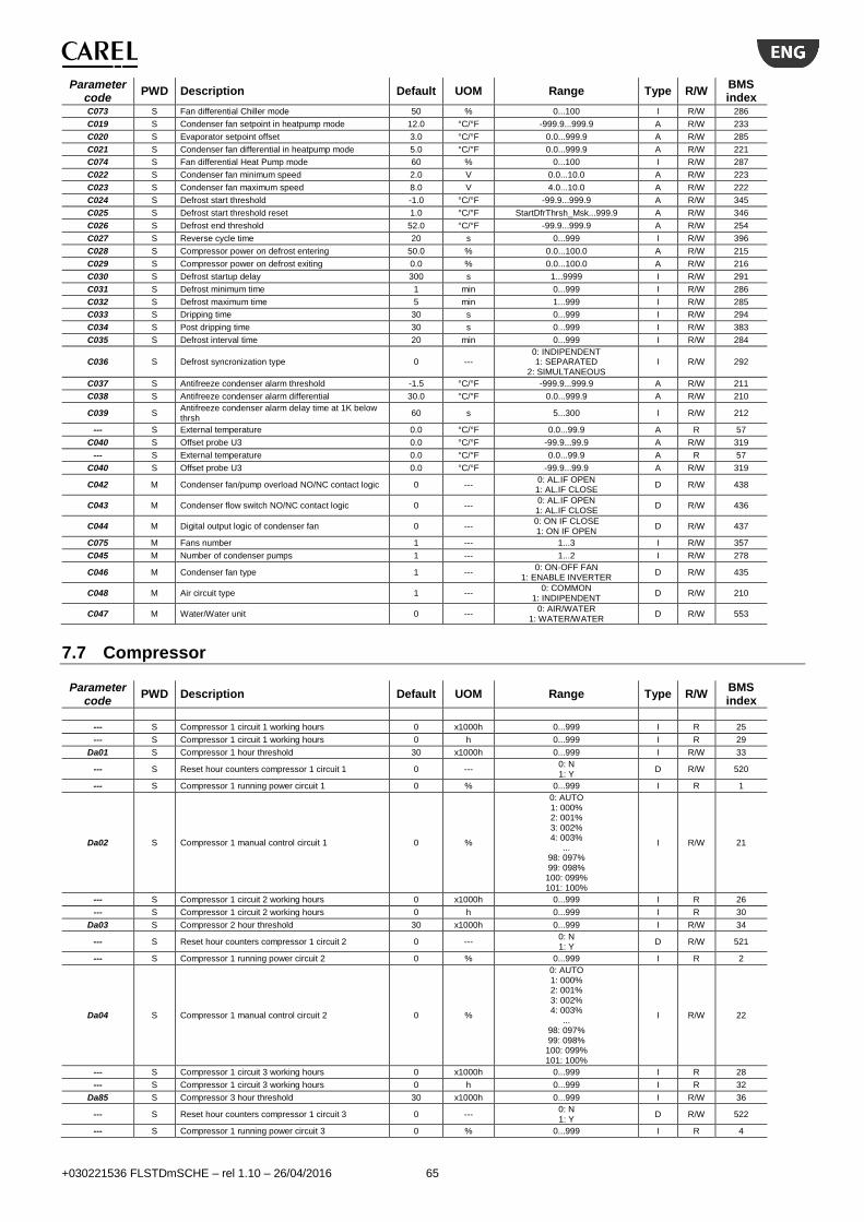
+030221536 FLSTDmSCHE – rel 1.10 – 26/04/2016 65
Parameter code
PWD Description Default UOM Range Type R/W BMS index
C073 S Fan differential Chiller mode 50 % 0...100 I R/W 286
C019 S Condenser fan setpoint in heatpump mode 12.0 °C/°F -999.9...999.9 A R/W 233
C020 S Evaporator setpoint offset 3.0 °C/°F 0.0...999.9 A R/W 285
C021 S Condenser fan differential in heatpump mode 5.0 °C/°F 0.0...999.9 A R/W 221
C074 S Fan differential Heat Pump mode 60 % 0...100 I R/W 287
C022 S Condenser fan minimum speed 2.0 V 0.0...10.0 A R/W 223
C023 S Condenser fan maximum speed 8.0 V 4.0...10.0 A R/W 222
C024 S Defrost start threshold -1.0 °C/°F -99.9...999.9 A R/W 345
C025 S Defrost start threshold reset 1.0 °C/°F StartDfrThrsh_Msk...999.9 A R/W 346
C026 S Defrost end threshold 52.0 °C/°F -99.9...999.9 A R/W 254
C027 S Reverse cycle time 20 s 0...999 I R/W 396
C028 S Compressor power on defrost entering 50.0 % 0.0...100.0 A R/W 215
C029 S Compressor power on defrost exiting 0.0 % 0.0...100.0 A R/W 216
C030 S Defrost startup delay 300 s 1...9999 I R/W 291
C031 S Defrost minimum time 1 min 0...999 I R/W 286
C032 S Defrost maximum time 5 min 1...999 I R/W 285
C033 S Dripping time 30 s 0...999 I R/W 294
C034 S Post dripping time 30 s 0...999 I R/W 383
C035 S Defrost interval time 20 min 0...999 I R/W 284
C036 S Defrost syncronization type 0 --- 0: INDIPENDENT 1: SEPARATED
2: SIMULTANEOUS I R/W 292
C037 S Antifreeze condenser alarm threshold -1.5 °C/°F -999.9...999.9 A R/W 211
C038 S Antifreeze condenser alarm differential 30.0 °C/°F 0.0...999.9 A R/W 210
C039 S Antifreeze condenser alarm delay time at 1K below thrsh
60 s 5...300 I R/W 212
--- S External temperature 0.0 °C/°F 0.0...99.9 A R 57
C040 S Offset probe U3 0.0 °C/°F -99.9...99.9 A R/W 319
--- S External temperature 0.0 °C/°F 0.0...99.9 A R 57
C040 S Offset probe U3 0.0 °C/°F -99.9...99.9 A R/W 319
C042 M Condenser fan/pump overload NO/NC contact logic 0 --- 0: AL.IF OPEN 1: AL.IF CLOSE
D R/W 438
C043 M Condenser flow switch NO/NC contact logic 0 --- 0: AL.IF OPEN 1: AL.IF CLOSE
D R/W 436
C044 M Digital output logic of condenser fan 0 --- 0: ON IF CLOSE 1: ON IF OPEN
D R/W 437
C075 M Fans number 1 --- 1...3 I R/W 357
C045 M Number of condenser pumps 1 --- 1...2 I R/W 278
C046 M Condenser fan type 1 --- 0: ON-OFF FAN
1: ENABLE INVERTER D R/W 435
C048 M Air circuit type 1 --- 0: COMMON
1: INDIPENDENT D R/W 210
C047 M Water/Water unit 0 --- 0: AIR/WATER
1: WATER/WATER D R/W 553
7.7 Compressor
Parameter code
PWD Description Default UOM Range Type R/W BMS index
--- S Compressor 1 circuit 1 working hours 0 x1000h 0...999 I R 25
--- S Compressor 1 circuit 1 working hours 0 h 0...999 I R 29
Da01 S Compressor 1 hour threshold 30 x1000h 0...999 I R/W 33
--- S Reset hour counters compressor 1 circuit 1 0 --- 0: N 1: Y
D R/W 520
--- S Compressor 1 running power circuit 1 0 % 0...999 I R 1
Da02 S Compressor 1 manual control circuit 1 0 %
0: AUTO 1: 000% 2: 001% 3: 002% 4: 003%
... 98: 097% 99: 098%
100: 099% 101: 100%
I R/W 21
--- S Compressor 1 circuit 2 working hours 0 x1000h 0...999 I R 26
--- S Compressor 1 circuit 2 working hours 0 h 0...999 I R 30
Da03 S Compressor 2 hour threshold 30 x1000h 0...999 I R/W 34
--- S Reset hour counters compressor 1 circuit 2 0 --- 0: N 1: Y
D R/W 521
--- S Compressor 1 running power circuit 2 0 % 0...999 I R 2
Da04 S Compressor 1 manual control circuit 2 0 %
0: AUTO 1: 000% 2: 001% 3: 002% 4: 003%
... 98: 097% 99: 098%
100: 099% 101: 100%
I R/W 22
--- S Compressor 1 circuit 3 working hours 0 x1000h 0...999 I R 28
--- S Compressor 1 circuit 3 working hours 0 h 0...999 I R 32
Da85 S Compressor 3 hour threshold 30 x1000h 0...999 I R/W 36
--- S Reset hour counters compressor 1 circuit 3 0 --- 0: N 1: Y
D R/W 522
--- S Compressor 1 running power circuit 3 0 % 0...999 I R 4
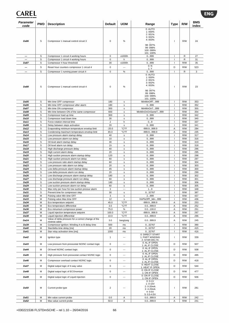
+030221536 FLSTDmSCHE – rel 1.10 – 26/04/2016 66
Parameter code
PWD Description Default UOM Range Type R/W BMS index
Da86 S Compressor 1 manual control circuit 3 0 %
0: AUTO 1: 000% 2: 001% 3: 002% 4: 003%
... 98: 097% 99: 098%
100: 099% 101: 100%
I R/W 24
--- S Compressor 1 circuit 4 working hours 0 x1000h 0...999 I R 27
--- S Compressor 1 circuit 4 working hours 0 h 0...999 I R 31
Da87 S Compressor 4 hour threshold 30 x1000h 0...999 I R/W 35
--- S Reset hour counters compressor 1 circuit 4 0 --- 0: N 1: Y
D R/W 523
--- S Compressor 1 running power circuit 4 0 % 0...999 I R 3
Da88 S Compressor 1 manual control circuit 4 0 %
0: AUTO 1: 000% 2: 001% 3: 002% 4: 003%
... 98: 097% 99: 098%
100: 099% 101: 100%
I R/W 23
Da05 S Min time OFF compressor 180 s MinMinOffT...999 I R/W 353
Da06 S Min time OFF compressor after alarm 180 s 0...999 I R/W 352
Da07 S Min time ON compressor 300 s MinMinOnT...999 I R/W 355
Da08 S Min time between ON of the same compressor 600 s MinMinOnOnSameT...999 I R/W 354
Da09 S Compressor load up time 300 s 0...999 I R/W 342
Da10 S Compressor load down time 30 s 0...999 I R/W 340
Da11 S Force rotation interval time 2 h 0...9 I R/W 337
Da99 S Delay between steps activation 20 s 0...999 I R/W 341
Da12 S Evaporating minimum temperature envelop limit -20.0 °C/°F -999.9...999.9 A R/W 284
Da13 S Condensing maximum temperature envelop limit 65.0 °C/°F -999.9...999.9 A R/W 235
Da14 S Low pressure alarm startup delay 40 s 0...999 I R/W 317
Da15 S Low pressure alarm run delay 10 s 0...999 I R/W 316
Da16 S Oil level alarm startup delay 30 s 0...999 I R/W 319
Da17 S Oil level alarm run delay 15 s 0...999 I R/W 318
Da18 S High discharge pressure delay 40 s 0...999 I R/W 296
Da19 S High current alarm delay 20 s 0...999 I R/W 295
Da20 S High suction pressure alarm startup delay 120 s 0...999 I R/W 298
Da21 S High suction pressure alarm run delay 60 s 0...999 I R/W 297
Da22 S Low pressure ratio alarm startup delay 60 s 0...999 I R/W 304
Da23 S Low pressure ratio alarm run delay 20 s 0...999 I R/W 303
Da24 S Low delta pressure alarm startup delay 45 s 0...999 I R/W 300
Da25 S Low delta pressure alarm run delay 20 s 0...999 I R/W 299
Da26 S Low discharge pressure alarm startup delay 180 s 0...999 I R/W 302
Da27 S Low discharge pressure alarm run delay 60 s 0...999 I R/W 301
Da28 S Low suction pressure alarm startup delay 180 s 0...999 I R/W 306
Da29 S Low suction pressure alarm run delay 60 s 0...999 I R/W 305
Da30 S Max retry per hour for low suction pressur alarm 3 --- 1...9 I R/W 348
Da31 S Prevent time for compressor step 30 s 0...32767 I R/W 387
Da32 M Pulsing valve Min time OFF 3 s 2...999 I R/W 437
Da33 M Pulsing valve Max time OFF 12 s VlvPlsOffT_Min...999 I R/W 436
Da34 M Eco temperature setpoint 45.0 °C/°F -999.9...999.9 A R/W 253
Da35 M Eco temperature differential 3.0 °C/°F 0.0...999.9 A R/W 252
Da36 M Eco minumum compressor power 75.0 % 0.0...100.0 A R/W 251
Da37 M Liquid injection temperature setpoint 100.0 °C/°F -999.9...999.9 A R/W 297
Da38 M Liquid injection differential 10.0 °C/°F 0.0...999.9 A R/W 296
Da2A M Value of delta pressure for a correct change of the reverse valve
3.0 barg/psig 0.0...999.9 A R/W 245
Da39 M Compressor ignition: Winding A to B delay time 500 ms 0...32767 I R/W 390
Da40 M Star/delta time delay [ms] 20 ms 0...32767 I R/W 415
Da41 M Star relay activation time [ms] 1000 ms 0...32767 I R/W 416
Da42 M Ignition type 1 --- 0: DIRECT START 1: PART WINDING
2: STAR-DELTA I R/W 339
Da43 M Low pressure from pressostat NO/NC contact logic 0 --- 0: AL.IF OPEN 1: AL.IF CLOSE
D R/W 507
Da44 M Oil level NO/NC contact logic 0 --- 0: AL.IF OPEN 1: AL.IF CLOSE
D R/W 508
Da45 M High pressure from pressostat contact NO/NC logic 0 --- 0: AL.IF OPEN 1: AL.IF CLOSE
D R/W 495
Da46 M Compressor overload contact NO/NC logic 0 --- 0: AL.IF OPEN 1: AL.IF CLOSE
D R/W 418
Da47 M Digital output logic of 4-way valve 0 --- 0: HEAT CLOSE
1: HEAT IF OPEN D R/W 544
Da48 M Digital output logic of ECOnomizer 0 --- 0: ON IF CLOSE 1: ON IF OPEN
D R/W 477
Da49 M Digital output logic of Liquid injection 0 --- 0: ON IF CLOSE 1: ON IF OPEN
D R/W 506
Da50 M Current probe type 2 ---
0: 0-1V 1: 0-10V
2: 0-20mA 3: 4-20mA
4: 0-5V 5: 0.5-4.5V
I R/W 281
Da51 M Min value current probe 0.0 A 0.0...999.9 A R/W 242
Da52 M Max value current probe 50.0 A 0.0...999.9 A R/W 241

+030221536 FLSTDmSCHE – rel 1.10 – 26/04/2016 67
Parameter code
PWD Description Default UOM Range Type R/W BMS index
--- S Current compressor 1 circuit 1 0.0 A -999.9...999.9 A R 61
Da53 S Offset current probe compressor 1 0.0 A -99.9...99.9 A R/W 237
--- S Current compressor 1 circuit 2 0.0 A -999.9...999.9 A R 62
Da54 S Offset current probe compressor 2 0.0 A -99.9...99.9 A R/W 238
--- S Current compressor 1 circuit 3 0.0 A -999.9...999.9 A R 64
Da89 S Offset current probe compressor 3 0.0 A -99.9...99.9 A R/W 239
--- S Current compressor 1 circuit 4 0.0 A -999.9...999.9 A R 63
Da90 S Offset current probe compressor 4 0.0 A -99.9...99.9 A R/W 240
Da55 M Probe type suction pressure 0 ---
0: RAZ. 0-5V 1: 4-20mA
2: 4-20mA REMOTE 3: 4-20mA EXTERNAL
I R/W 457
Da56 M Min value suction pressure probe 0.0 barg/psig A32_Msk_Lim_Min... A32_Msk_Lim_Max
A R/W 350
Da57 M Max value suction pressure probe 30.0 barg/psig A30_Msk_Lim_Min... A30_Msk_Lim_Max
A R/W 349
Da58 M Probe type suction temperature 0 ---
0: NTC CAREL 1: CAREL NTC-HT 2: NTC SPKP**T0
3: 0-10V EXT. SIGNAL
I R/W 458
Da59 M Suction temperature threshold probe low 0.0 °C/°F -999.9...999.9 A R/W 352
Da60 M Suction temperature threshold probe high 0.0 °C/°F -999.9...999.9 A R/W 351
--- S Suction pressure circuit 1 0.0 barg/psig -999.9...999.9 A R 33
Da61 S Suction pressure circuit 1 offset 0.0 barg/psig A34_Msk_Lim_Min... A34_Msk_Lim_Max
A R/W 327
--- S Suction temperature circuit 1 0.0 °C/°F -999.9...999.9 A R 41
Da62 S Suction temperature circuit 1 offset 0.0 °C/°F A41_Msk_Lim_Min... A41_Msk_Lim_Max
A R/W 331
--- S Suction pressure circuit 2 0.0 barg/psig -999.9...999.9 A R 34
Da63 S Suction pressure circuit 2 offset 0.0 barg/psig A34_Msk_Lim_Min... A34_Msk_Lim_Max
A R/W 328
--- S Suction temperature circuit 2 0.0 °C/°F -999.9...999.9 A R 42
Da64 S Suction temperature circuit 2 offset 0.0 °C/°F A41_Msk_Lim_Min... A41_Msk_Lim_Max
A R/W 332
--- S Suction pressure circuit 3 0.0 barg/psig -999.9...999.9 A R 36
Da91 S Suction pressure circuit 3 offset 0.0 barg/psig A34_Msk_Lim_Min... A34_Msk_Lim_Max
A R/W 329
--- S Suction temperature circuit 3 0.0 °C/°F -999.9...999.9 A R 44
Da92 S Suction temperature circuit 3 offset 0.0 °C/°F A41_Msk_Lim_Min... A41_Msk_Lim_Max
A R/W 333
--- S Suction pressure circuit 4 0.0 barg/psig -999.9...999.9 A R 35
Da93 S Suction pressure circuit 4 offset 0.0 barg/psig A34_Msk_Lim_Min... A34_Msk_Lim_Max
A R/W 330
--- S Suction temperature circuit 4 0.0 °C/°F -999.9...999.9 A R 43
Da94 S Suction temperature circuit 4 offset 0.0 °C/°F A41_Msk_Lim_Min... A41_Msk_Lim_Max
A R/W 334
Da65 M Probe type discharge pressure 0 ---
0: RAZ. 0-5V 1: 4-20mA
2: 4-20mA REMOTE 3: 4-20mA EXTERNAL
I R/W 459
Da66 M Min value discharge pressure probe 0.0 barg/psig A33_Msk_Lim_Min... A33_Msk_Lim_Max
A R/W 247
Da67 M Max value discharge pressure probe 30.0 barg/psig A31_Msk_Lim_Min... A31_Msk_Lim_Max
A R/W 246
Da68 M Probe type discharge temperature 0 --- 0: CAREL NTC
1: CAREL NTC-HT 2: NTC SPKP**T0
I R/W 460
Da69 M Discharge temperature probe min. value 0.0 °C/°F -999.9...999.9 A R/W 249
Da70 M Discharge temperature probe max. value 0.0 °C/°F -999.9...999.9 A R/W 248
--- S Discharge pressure circuit 1 0.0 barg/psig -999.9...999.9 A R 45
Da71 S Discharge pressure circuit 1 offset 0.0 barg/psig A35_Msk_Lim_Min... A35_Msk_Lim_Max
A R/W 335
--- S Discharge temperature circuit 1 0.0 °C/°F -999.9...999.9 A R 53
Da72 S Discharge temperature circuit 1 offset 0.0 °C/°F A42_Msk_Lim_Min... A42_Msk_Lim_Max
A R/W 339
--- S Discharge pressure circuit 2 0.0 barg/psig -999.9...999.9 A R 46
Da73 S Discharge pressure circuit 2 offset 0.0 barg/psig A35_Msk_Lim_Min... A35_Msk_Lim_Max
A R/W 336
--- S Discharge temperature circuit 2 0.0 °C/°F -999.9...999.9 A R 54
Da74 S Discharge temperature circuit 2 offset 0.0 °C/°F A42_Msk_Lim_Min... A42_Msk_Lim_Max
A R/W 340
--- S Discharge pressure circuit 3 0.0 barg/psig -999.9...999.9 A R 48
Da95 S Discharge pressure circuit 3 offset 0.0 barg/psig A35_Msk_Lim_Min... A35_Msk_Lim_Max
A R/W 337
--- S Discharge temperature circuit 3 0.0 °C/°F -999.9...999.9 A R 56
Da96 S Discharge temperature circuit 3 offset 0.0 °C/°F A42_Msk_Lim_Min... A42_Msk_Lim_Max
A R/W 341
--- S Discharge pressure circuit 4 0.0 barg/psig -999.9...999.9 A R 47
Da97 S Discharge pressure circuit 4 offset 0.0 barg/psig A35_Msk_Lim_Min... A35_Msk_Lim_Max
A R/W 338
--- S Discharge temperature circuit 4 0.0 °C/°F -999.9...999.9 A R 55
Da98 S Discharge temperature circuit 4 offset 0.0 °C/°F A42_Msk_Lim_Min... A42_Msk_Lim_Max
A R/W 342
Da75 M Rotation type 1 ---
0: --- 1: FIFO 2: LIFO
3: BY TIME
I R/W 398
Da76 M Devices unload sequence type 1 --- 0: ---
1: CCpppp 2: CppCpp
I R/W 283
Da1A M Compressor maximum operating current (SETPOINT)
0.0 amp 0.0...3276.7 A R/W 292
Da77 M Number of circuit in the unit 1 --- 1...4 I R/W 217

+030221536 FLSTDmSCHE – rel 1.10 – 26/04/2016 68
Parameter code
PWD Description Default UOM Range Type R/W BMS index
Da78 M Refrigerant type 1 ---
0: R22 1: R134a 2: R404A 3: R407C 4: R410A 5: R507 6: R290 7: R600
8: R600a 9: R717
10: R744 11: R728
12: R1270 13: R417A 14: R422d 15: R413A 16: R422A 17: R423A 18: R407A 19: R427A 20: R245fa 21: R407F
22: R32
I R/W 397
Da79 M Enable current probe 0 --- 0...1 D R/W 478
Da80 M Enable envelope prevent control 1 --- 0...1 D R/W 480
Da81 M Eco enable 0 --- 0...1 D R/W 479
Da82 M Enable liquid injection 0 --- 0...1 D R/W 483
Da83 M Compressor manufacturer 1 ---
0: CUSTOM 1: BITZER
2: REFCOMP 3: FRASCOLD 4: HANBELL 5: FUSHENG 6: J&E HALL
7: COPELAND
I R/W 262
Da84 M Compressor model 1 ---
0: CSH3 M1 R134a 1: CSH3 M1 50% R134a 2: CSH3 25% M1 R134a 3: CSH3 50% M1 R134a
4: CSH3 M2 R134a 5: CSH3 M2 50% R134a 6: CSH3 25% M2 R134a 7: CSH3 50% M2 R134a 8: CSH6553-8573 R407C
9: CSH6553-8573 25% R407C 10: CSH6553-8573 50% R407C
11: CSH8583/95103 R407C 12: CSH8583/95103 25% R407C 13: CSH8583/95103 50% R407C
14: CSW R134a 15: CSW 25% R134a 16: CSW 50% R134a
17: CSW R407C 18: CSW 25% R407C 19: CSW 50% R407C
20: CSVH24-125Y R134a 21: CSVH25-160Y R134a 22: CSVH26-200Y R134a
I R/W 263
Da84 M Compressor model 1 --- 0: STEP COMPRESSOR
1: STEPLESS COMPRESSOR 2: INVERTER COMPRESSOR
I R/W 263
Da84 M Compressor model 1 ---
0: 134-S R134a 1: 134-XS L1 R134a 2: 134-XS L2 R134a
3: 134-S R134a
I R/W 263
Da84 M Compressor model 1 ---
0: CXH MOTOR 1 25% R134a 1: CXH MOTOR 1 50% R134a 2: CXH MOTOR 2 25% R134a 3: CXH MOTOR 2 50% R134a
4: CXH MOTOR 1 R134a 5: CXH MOTOR 2 R134a
6: CXW MOTOR 1 25% R134a 7: CXW MOTOR 1 50% R134a
8: CXW MOTOR 1 R134a 9: CXHIT R134a
10: CXWIT R134a 11: CXH MOTOR 1 50% R134a 12: CXH MOTOR 2 50% R134a 13: CXW MOTOR 1 50% R134a
I R/W 263
Da84 M Compressor model 1 ---
0: RC2-200/930 M.A R134a 1: RC2-200/930 M.B R134a 2: RC2-200/930 M.A R134a 3: RC2-200/930 M.B R134a
4: RC2-1020/1530 M.A1 R134a 5: RC2-1020/1530 M.A2 R134a 6: RC2-1020/1530 M.B1 R134a
I R/W 263
Da84 M Compressor model 1 ---
0: SR R22 1: SR R134a 2: SR R22
3: SR R134a
I R/W 263
--- M Compressor type (visualization only) 0 ---
0: Error configuration! 1: Step,no env.data
2: Step 3: Stepless,no env.data
4: Stepless 5: Inverter,no env.data
6: Inverter
I R 264
--- M Compressor model msk 1 ---
0: STEP 1: STEP
2: STEPLESS 3: STEPLESS
4: STEP
I R

+030221536 FLSTDmSCHE – rel 1.10 – 26/04/2016 69
Parameter code
PWD Description Default UOM Range Type R/W BMS index
5: STEP 6: STEPLESS 7: STEPLESS
8: STEP 9: STEPLESS
10: STEPLESS 11: STEP
12: STEPLESS 13: STEPLESS
14: STEP 15: STEPLESS 16: STEPLESS
17: STEP 18: STEPLESS 19: STEPLESS 20: INVERTER 21: INVERTER 22: INVERTER
--- M Compressor model msk 1 --- 0: STEP
1: STEPLESS 2: INVERTER
I R
--- M Compressor model msk 1 ---
0: STEP 1: STEP 2: STEP
3: STEPLESS
I R
--- M Compressor model msk 1 ---
0: STEP 1: STEP 2: STEP 3: STEP
4: STEPLESS 5: STEPLESS
6: STEP 7: STEP
8: STEPLESS 9: INVERTER
10: INVERTER 11: STEPLESS 12: STEPLESS 13: STEPLESS
I R
--- M Compressor model msk 1 ---
0: STEPLESS 1: STEPLESS
2: STEP 3: STEP
4: STEPLESS 5: STEPLESS 6: STEPLESS
I R
--- M Compressor model msk 1 ---
0: STEP 1: STEP
2: STEPLESS 3: STEPLESS
I R
Db01 M Valve number 1 --- 1...4 I R/W 435
Db02 M Pulsing valve: increment pulse time 1.0 s 0.1...9.9 A R/W 358
Db03 M Pulsing valve: decrement pulse time 1.0 s 0.1...9.9 A R/W 357
Db04 M Compressor valves intermittent time 1 s 1...99 I R/W 434
Db10 M Compressor OFF: Valve 1 command type 1 --- 0: D; 1: O; 2: X; 3: I; 4: P; 5: N * I R/W 358
Db11 M Compressor startup phase 1: Valve 1 command type 1 --- 0: D; 1: O; 2: X; 3: I; 4: P; 5: N * I R/W 419
Db13 M Compressor phase 1: Valve 1 command type 1 --- 0: D; 1: O; 2: X; 3: I; 4: P; 5: N * I R/W 362
Db14 M Compressor phase 2: Valve 1 command type 1 --- 0: D; 1: O; 2: X; 3: I; 4: P; 5: N * I R/W 366
Db15 M Compressor phase 3: Valve 1 command type 1 --- 0: D; 1: O; 2: X; 3: I; 4: P; 5: N * I R/W 370
Db16 M Compressor phase 4: Valve 1 command type 1 --- 0: D; 1: O; 2: X; 3: I; 4: P; 5: N * I R/W 374
Db17 M Compressor shutdown phase 1: Valve 1 command type
1 --- 0: D; 1: O; 2: X; 3: I; 4: P; 5: N * I R/W 401
Db20 M Compressor OFF: Valve 2 command type 1 --- 0: D; 1: O; 2: X; 3: I; 4: P; 5: N * I R/W 359
Db21 M Compressor startup phase 1: Valve 2 command type 1 --- 0: D; 1: O; 2: X; 3: I; 4: P; 5: N * I R/W 420
Db23 M Compressor phase 1: Valve 2 command type 1 --- 0: D; 1: O; 2: X; 3: I; 4: P; 5: N * I R/W 363
Db24 M Compressor phase 2: Valve 2 command type 1 --- 0: D; 1: O; 2: X; 3: I; 4: P; 5: N * I R/W 367
Db25 M Compressor phase 3: Valve 2 command type 1 --- 0: D; 1: O; 2: X; 3: I; 4: P; 5: N * I R/W 371
Db26 M Compressor phase 4: Valve 2 command type 1 --- 0: D; 1: O; 2: X; 3: I; 4: P; 5: N * I R/W 375
Db27 M Compressor shutdown phase 1: Valve 2 command type
1 --- 0: D; 1: O; 2: X; 3: I; 4: P; 5: N * I R/W 402
Db30 M Compressor OFF: Valve 3 command type 1 --- 0: D; 1: O; 2: X; 3: I; 4: P; 5: N * I R/W 360
Db31 M Compressor startup phase 1: Valve 3 command type 1 --- 0: D; 1: O; 2: X; 3: I; 4: P; 5: N * I R/W 421
Db33 M Compressor phase 1: Valve 3 command type 1 --- 0: D; 1: O; 2: X; 3: I; 4: P; 5: N * I R/W 364
Db34 M Compressor phase 2: Valve 3 command type 1 --- 0: D; 1: O; 2: X; 3: I; 4: P; 5: N * I R/W 368
Db35 M Compressor phase 3: Valve 3 command type 1 --- 0: D; 1: O; 2: X; 3: I; 4: P; 5: N * I R/W 372
Db36 M Compressor phase 4: Valve 3 command type 1 --- 0: D; 1: O; 2: X; 3: I; 4: P; 5: N * I R/W 376
Db37 M Compressor shutdown phase 1: Valve 3 command type
1 --- 0: D; 1: O; 2: X; 3: I; 4: P; 5: N * I R/W 403
Db40 M Compressor OFF: Valve 4 command type 1 --- 0: D; 1: O; 2: X; 3: I; 4: P; 5: N * I R/W 361
Db41 M Compressor startup phase 1: Valve 4 command type 1 --- 0: D; 1: O; 2: X; 3: I; 4: P; 5: N * I R/W 422
Db43 M Compressor phase 1: Valve 4 command type 1 --- 0: D; 1: O; 2: X; 3: I; 4: P; 5: N * I R/W 365
Db44 M Compressor phase 2: Valve 4 command type 1 --- 0: D; 1: O; 2: X; 3: I; 4: P; 5: N * I R/W 369
Db45 M Compressor phase 3: Valve 4 command type 1 --- 0: D; 1: O; 2: X; 3: I; 4: P; 5: N * I R/W 373
Db46 M Compressor phase 4: Valve 4 command type 1 --- 0: D; 1: O; 2: X; 3: I; 4: P; 5: N * I R/W 377
Db47 M Compressor shutdown phase 1: Valve 4 command type
1 --- 0: D; 1: O; 2: X; 3: I; 4: P; 5: N * I R/W 404
Db10 M Compressor OFF: Valve 1 command type 1 --- 0: D; 1: O; 2: X; 3: I; 4: P; 5: N * I R/W 358
Db11 M Compressor startup phase 1: Valve 1 command type 1 --- 0: D; 1: O; 2: X; 3: I; 4: P; 5: N * I R/W 419
Db12 M Compressor startup phase 2: Valve 1 command type 1 --- 0: D; 1: O; 2: X; 3: I; 4: P; 5: N * I R/W 423
Db13 M Compressor phase 1: Valve 1 command type 1 --- 0: D; 1: O; 2: X; 3: I; 4: P; 5: N * I R/W 362
Db14 M Compressor phase 2: Valve 1 command type 1 --- 0: D; 1: O; 2: X; 3: I; 4: P; 5: N * I R/W 366
Db15 M Compressor phase 3: Valve 1 command type 1 --- 0: D; 1: O; 2: X; 3: I; 4: P; 5: N * I R/W 370
Db17 M Compressor shutdown phase 1: Valve 1 command type
1 --- 0: D; 1: O; 2: X; 3: I; 4: P; 5: N * I R/W 401

+030221536 FLSTDmSCHE – rel 1.10 – 26/04/2016 70
Parameter code
PWD Description Default UOM Range Type R/W BMS index
Db18 M Compressor shutdown phase 2: Valve 1 command type
1 --- 0: D; 1: O; 2: X; 3: I; 4: P; 5: N * I R/W 405
Db20 M Compressor OFF: Valve 2 command type 1 --- 0: D; 1: O; 2: X; 3: I; 4: P; 5: N * I R/W 359
Db21 M Compressor startup phase 1: Valve 2 command type 1 --- 0: D; 1: O; 2: X; 3: I; 4: P; 5: N * I R/W 420
Db22 M Compressor startup phase 2: Valve 2 command type 1 --- 0: D; 1: O; 2: X; 3: I; 4: P; 5: N * I R/W 424
Db23 M Compressor phase 1: Valve 2 command type 1 --- 0: D; 1: O; 2: X; 3: I; 4: P; 5: N * I R/W 363
Db24 M Compressor phase 2: Valve 2 command type 1 --- 0: D; 1: O; 2: X; 3: I; 4: P; 5: N * I R/W 367
Db25 M Compressor phase 3: Valve 2 command type 1 --- 0: D; 1: O; 2: X; 3: I; 4: P; 5: N * I R/W 371
Db27 M Compressor shutdown phase 1: Valve 2 command type
1 --- 0: D; 1: O; 2: X; 3: I; 4: P; 5: N * I R/W 402
Db28 M Compressor shutdown phase 2: Valve 2 command type
1 --- 0: D; 1: O; 2: X; 3: I; 4: P; 5: N * I R/W 406
Db30 M Compressor OFF: Valve 3 command type 1 --- 0: D; 1: O; 2: X; 3: I; 4: P; 5: N * I R/W 360
Db31 M Compressor startup phase 1: Valve 3 command type 1 --- 0: D; 1: O; 2: X; 3: I; 4: P; 5: N * I R/W 421
Db32 M Compressor startup phase 2: Valve 3 command type 1 --- 0: D; 1: O; 2: X; 3: I; 4: P; 5: N * I R/W 425
Db33 M Compressor phase 1: Valve 3 command type 1 --- 0: D; 1: O; 2: X; 3: I; 4: P; 5: N * I R/W 364
Db34 M Compressor phase 2: Valve 3 command type 1 --- 0: D; 1: O; 2: X; 3: I; 4: P; 5: N * I R/W 368
Db35 M Compressor phase 3: Valve 3 command type 1 --- 0: D; 1: O; 2: X; 3: I; 4: P; 5: N * I R/W 372
Db37 M Compressor shutdown phase 1: Valve 3 command type
1 --- 0: D; 1: O; 2: X; 3: I; 4: P; 5: N * I R/W 403
Db38 M Compressor shutdown phase 2: Valve 3 command type
1 --- 0: D; 1: O; 2: X; 3: I; 4: P; 5: N * I R/W 407
Db40 M Compressor OFF: Valve 4 command type 1 --- 0: D; 1: O; 2: X; 3: I; 4: P; 5: N * I R/W 361
Db41 M Compressor startup phase 1: Valve 4 command type 1 --- 0: D; 1: O; 2: X; 3: I; 4: P; 5: N * I R/W 422
Db42 M Compressor startup phase 2: Valve 4 command type 1 --- 0: D; 1: O; 2: X; 3: I; 4: P; 5: N * I R/W 426
Db43 M Compressor phase 1: Valve 4 command type 1 --- 0: D; 1: O; 2: X; 3: I; 4: P; 5: N * I R/W 365
Db44 M Compressor phase 2: Valve 4 command type 1 --- 0: D; 1: O; 2: X; 3: I; 4: P; 5: N * I R/W 369
Db45 M Compressor phase 3: Valve 4 command type 1 --- 0: D; 1: O; 2: X; 3: I; 4: P; 5: N * I R/W 373
Db47 M Compressor shutdown phase 1: Valve 4 command type
1 --- 0: D; 1: O; 2: X; 3: I; 4: P; 5: N * I R/W 404
Db48 M Compressor shutdown phase 2: Valve 4 command type
1 --- 0: D; 1: O; 2: X; 3: I; 4: P; 5: N * I R/W 408
Db50 M Compressor startup phase 1 time 10 s 0...9999 I R/W 428
Db51 M Compressor shutdown phase 1 time 10 s 0...9999 I R/W 410
Db52 M Start/stop power 25.0 % 0.0...100.0 A R/W 347
Db53 M Number of compressor steps 1 --- 1...4 I R/W 431
Db54 M Compressor power step 1 25.0 % 0.0...100.0 A R/W 320
Db55 M Compressor power step 2 50.0 % 0.0...100.0 A R/W 321
Db56 M Compressor power step 3 75.0 % 0.0...100.0 A R/W 322
Db57 M Step 1 - Step 2 delay 10 s 0...9999 I R/W 321
Db58 M Step 2 - Step 3 delay 10 s 0...9999 I R/W 322
Db59 M Step 3 - Step 4 delay 10 s 0...9999 I R/W 323
Db61 M Compressor startup phase 2 time 0 s 0...9999 I R/W 427
Db63 M Compressor shutdown phase 2 time 0 s 0...9999 I R/W 409
Db65 M Min power of stepless compressor 25.0 % 0.0...100.0 A R/W 307
Db66 M Min power reach time for stepless control 60 s 0...9999 I R/W 356
Db67 M Max power reach time for stepless control 60 s 0...9999 I R/W 347
Db68 M MinInputValue of Min time OFF compressor 60 s 0...999 I R/W 349
Db69 M MinInputValue of Min time ON compressor 240 s 0...999 I R/W 351
Db70 M MinInputValue of Min time between ON of the same compressor
360 s 0...999 I R/W 350
Db71 M Envelope condensing min temperature 0.0 °C/°F -999.9...999.9 A R/W 257
Db72 M Envelope condensing max temperature 0.0 °C/°F -999.9...999.9 A R/W 255
Db73 M Envelope evaporating min temperature 0.0 °C/°F -999.9...999.9 A R/W 262
Db74 M Envelope evaporating max temperature 0.0 °C/°F -999.9...999.9 A R/W 260
Db75 M Envelope max condensing temperature in Eco mode 0.0 °C/°F -999.9...999.9 A R/W 256
Db76 M Envelope max evaporating temperature in Eco mode 0.0 °C/°F -999.9...999.9 A R/W 261
Db77 M Envelope max current segment X1 0.0 °C/°F -999.9...999.9 A R/W 268
Db78 M Envelope max current segment Y1 0.0 °C/°F -999.9...999.9 A R/W 278
Db79 M Envelope max current segment X2 0.0 °C/°F -999.9...999.9 A R/W 273
Db80 M Envelope max current segment Y2 0.0 °C/°F -999.9...999.9 A R/W 283
Db81 M Envelope min compression rate segment X1 0.0 °C/°F -999.9...999.9 A R/W 267
Db82 M Envelope min compression rate segment Y1 0.0 °C/°F -999.9...999.9 A R/W 277
Db83 M Envelope min compression rate segment X2 0.0 °C/°F -999.9...999.9 A R/W 272
Db84 M Envelope min compression rate segment Y2 0.0 °C/°F -999.9...999.9 A R/W 282
Db85 M Envelope min delta pressure segment X1 0.0 °C/°F -999.9...999.9 A R/W 265
Db86 M Envelope min delta pressure segment Y1 0.0 °C/°F -999.9...999.9 A R/W 275
Db87 M Envelope min delta pressure segment X2 0.0 °C/°F -999.9...999.9 A R/W 270
Db88 M Envelope min delta pressure segment Y2 0.0 °C/°F -999.9...999.9 A R/W 280
Db89 M Envelope max compressione rate segment X1 0.0 °C/°F -999.9...999.9 A R/W 266
Db90 M Envelope max compressione rate segment Y1 0.0 °C/°F -999.9...999.9 A R/W 276
Db91 M Envelope max compressione rate segment X2 0.0 °C/°F -999.9...999.9 A R/W 271
Db92 M Envelope max compressione rate segment Y2 0.0 °C/°F -999.9...999.9 A R/W 281
Db93 M Envelope max capacity segment X1 0.0 °C/°F -999.9...999.9 A R/W 264
Db94 M Envelope max capacity segment Y1 0.0 °C/°F -999.9...999.9 A R/W 274
Db95 M Envelope max capacity segment X2 0.0 °C/°F -999.9...999.9 A R/W 269
Db96 M Envelope max capacity segment Y2 0.0 °C/°F -999.9...999.9 A R/W 279
Db97 M Envelope max capacity limit 75.0 % 0.0...100.0 A R/W 263
Db98 M Envelope discharge min temperature 60.0 °C/°F -999.9...999.9 A R/W 259
Db99 M Envelope discharge max temperature 120.0 °C/°F -999.9...999.9 A R/W 258
Dc01 M Compressor inverter alarm contact NO/NC logic 0 --- 0: AL.IF OPEN 1: AL.IF CLOSE
D R/W 496
Dc02 M Inverter RUN NO/NC contact logic 1 --- 0: RUN IF OPEN
1: RUN IF CLOSE D R/W 499
Dc03 M Inverter Start NO/NC contact logic 0 --- 0: ON IF CLOSE D R/W 500

+030221536 FLSTDmSCHE – rel 1.10 – 26/04/2016 71
Parameter code
PWD Description Default UOM Range Type R/W BMS index
1: ON IF OPEN
Dc04 M Inverter Emergency shut-off NO/NC contact logic 1 --- 0: ON IF CLOSE 1: ON IF OPEN
D R/W 498
Dc05 M Inverter Alarm reset NO/NC contact logic 0 --- 0: ON IF CLOSE 1: ON IF OPEN
D R/W 497
Dc06 M Inverter minimum frequency 30.0 Hz 0.0...99.9 A R/W 295
Dc07 M Inverter maximum frequency 70.0 Hz 0.0...999.0 A R/W 294
Dc08 M Inverter compressor StartUp time 30 s 0…999 I R/W 464
Dc09 M Inverter compressor ShutOff time 30 s 0…999 I R/W 465
Dc10 M Enable Modbus Master (3.0) inverter communication 0 --- 0...1 D R/W 580
Dc11 M Inverter compressor address comp1 circ1 1 --- 1…255 I R/W 466
Dc12 M Inverter compressor address comp1 circ2 2 --- 1…255 I R/W 467
* D: Disable; O: Open; X: Closed; I: Intermittent; P: Pulsing; N: Negative pulsing
7.8 HW-SW
Parameter code
PWD Description Default UOM Range Type R/W BMS index
E001 S Unit of measurement for temperature (0: °C; 1: °F) 0 --- 0: INTERNATIONAL (ßC)
1: IMPERIAL (ßF) D R/W 92
E002 S Unit of measurement for pressure (0: barg; 1: psig) 0 --- 0: INTERNATIONAL (barg)
1: IMPERIAL (psig) D R/W 93
E003 S Date format 1 ---
0: --- 1: DD/MM/YY 2: MM/DD/YY 3: YY.MM.DD
I R/W 282
E004 S Protocol type on BMS port 2 ---
0: NONE 1: CAREL RS485
2: MODBUS RS485 3: pCO MANAGER
I R/W 388
E005 S BMS speed 4 ---
0: 1200bps 1: 2400bps 2: 4800bps 3: 9600bps
4: 19200bps
I R/W 215
E006 S BMS Adress 1 --- 0...207 I R/W 208
E007 S Protocol type on slave port BMS2 2 ---
0: NONE 1: CAREL RS485
2: MODBUS RS485 3: pCO MANAGER
I R/W 389
E008 S BMS2 baudrate 4 ---
0: 1200bps 1: 2400bps 2: 4800bps 3: 9600bps
4: 19200bps
I R/W 216
E009 S BMS2 adress 1 --- 00: N 1: Y
...207 I R/W 209
E011 S Reset hour counters 0 --- 0: N 1: Y
D R/W 519
E012 M Enable IO test 0 --- 0...1 D R/W 482
E018 M IO test board selection 0 --- 0: MASTER 1: SLAVE
D R/W 501
E013 M Digital output test channel 1 --- 0...30 I R/W 293
E014 M Digital output test value 0 --- 0: OPEN
1: CLOSE D R/W 472
E015 M Analogue output test channel 1 --- 0...6 I R/W 214
E016 M Analogue output test value 0.0 % 0.0...100.0 A R/W 214
E017 M Default installation 0 --- 0: NO 1: YES
I R/W 463
E017 M Default installation 0 --- 0
1: Please wait... I R 463
7.9 Log-Out
Parameter code
PWD Description Default UOM Range Type R/W BMS index
--- U Password run 0 ---
0: --- 1: User
2: Service 3: Manufacturer
I R
F001 U New user password 1234 --- 0...9999 I R/W
F002 S New service password 1234 --- 0...9999 I R/W
F003 M Manufacturer password 1234 --- 0...9999 I R/W

+030221536 FLSTDmSCHE – rel 1.10 – 26/04/2016 72
8. SUPERVISOR TABLE FLSTDmSCHE can be connected to various systems of supervision, in particular can be used the following communication protocols BMS: Carel and Modbus. The connection is done by means of a BMS serial port. The various connection protocols are managed by the following option cards:
Carel RS485: code PCOS004850
Modbus RS485: code PCOS004850 The Modbus® address is the address specified in the Modbus® frame. The following tables shows the variables sent to the supervisor.
Note: In the column indexes are shown Carel addresses of consecutive indices, but the Carel protocol only handles up at the 207 analog, 207 and 207 of the entire digital.
8.1 Analog variables
MB Index
Carel index
Par. code
Description Def. UOM Range R/W Variable name
1 1 --- Inverter frequency compressor 1 circuit 1 0 --- 0...999.9 R Comp1Circ1InvFreq
2 2 --- Inverter frequency compressor 1 circuit 2 0 --- 0...999.9 R Comp1Circ2InvFreq
3 3 --- Inverter frequency compressor 1 circuit 4 0 --- 0...999.9 R Comp1Circ4InvFreq
4 4 --- Inverter frequency compressor 1 circuit 3 0 --- 0...999.9 R Comp1Circ3InvFreq
5 5 --- Condenser fan setpoint circuit 2 13.0 °C/°F 0...999.9 R CondFanSetPCirc2_Msk
6 6 --- Condenser fan setpoint circuit 1 13.0 °C/°F 0...999.9 R CondFanSetPCirc1_Msk
7 7 --- Condenser fan setpoint circuit 4 13.0 °C/°F 0...999.9 R CondFanSetPCirc4_Msk
8 8 --- Condenser fan setpoint circuit 3 13.0 °C/°F 0...999.9 R CondFanSetPCirc3_Msk
9 9 --- Condenser fan 1 output request circuit 1 13.0 % 0...999.9 R CondFanCirc1
10 10 --- Condenser fan output request circuit 2 13.0 % 0...999.9 R CondFanCirc2
11 11 --- Condenser fan output request circuit 4 13.0 % 0...999.9 R CondFanCirc4
12 12 --- Condenser fan output request circuit 3 13.0 % 0...999.9 R CondFanCirc3
13 13 --- Discharge Superheat circuit 2 0 °C/°F -3276.8...3276.7 R DscgSH_Circ2_Msk
14 14 --- Discharge Superheat circuit 1 0 °C/°F -3276.8...3276.7 R DscgSH_Circ1_Msk
15 15 --- Discharge Superheat circuit 4 0 °C/°F -3276.8...3276.7 R DscgSH_Circ4_Msk
16 16 --- Discharge Superheat circuit 3 0 °C/°F -3276.8...3276.7 R DscgSH_Circ3_Msk
17 17 --- Superheat circuit 2 0 °C/°F -3276.8...3276.7 R SH_Circ2_Msk
18 18 --- Superheat circuit 1 0 °C/°F -3276.8...3276.7 R SH_Circ1_Msk
19 19 --- Superheat circuit 4 0 °C/°F -3276.8...3276.7 R SH_Circ4_Msk
20 20 --- Superheat circuit 3 0 °C/°F -3276.8...3276.7 R SH_Circ3_Msk
21 21 --- Valve opening percent circuit 1 0 --- 0...100.0 R A17_EEV_POSITION_PERC
ENT_SHOW
22 22 --- Valve opening percent circuit 2 0 --- 0...100.0 R A17_EEV_POSITION_PERC
ENT_SHOW
23 23 --- Valve opening percent circuit 3 0 --- 0...100.0 R EVO3_A17_EEV_POSITION_
PERC_SHOW
24 24 --- Valve opening percent circuit 4 0 --- 0...100.0 R EVO4_A17_EEV_POSITION_
PERC_SHOW
25 25 --- Outlet water temperature 0 °C/°F -999.9...999.9 R W_OutTemp_Msk
26 26 --- Inlet water temperature 0 °C/°F 0...99.9 R W_InTemp_Msk
27 27 --- Actual setpoint 0 °C/°F 0...999.9 R SetP_Act_Msk
28 28 --- Power request 0 % 0...999.9 R PwrReq
29 29 --- Inverter request to compressor 1 circuit 1 0 --- 0...100.0 R Comp1Circ1InvReq
30 30 --- Inverter request to compressor 1 circuit 2 0 --- 0...100.0 R Comp1Circ2InvReq
31 31 --- Inverter request to compressor 1 circuit 3 0 --- 0...100.0 R Comp1Circ3InvReq
32 32 --- Inverter request to compressor 1 circuit 4 0 --- 0...100.0 R Comp1Circ4InvReq
33 33 --- Suction pressure circuit 1 0 barg/psig -999.9...999.9 R SuctP_Circ1_Msk
34 34 --- Suction pressure circuit 2 0 barg/psig -999.9...999.9 R SuctP_Circ2_Msk
35 35 --- Suction pressure circuit 4 0 barg/psig -999.9...999.9 R SuctP_Circ4_Msk
36 36 --- Suction pressure circuit 3 0 barg/psig -999.9...999.9 R SuctP_Circ3_Msk
37 37 --- Evaporation temperature circuit 1 0 °C/°F -999.9...999.9 R EvapTempCirc1_Msk
38 38 --- Evaporation temperature circuit 2 0 °C/°F -999.9...999.9 R EvapTempCirc2_Msk
39 39 --- Evaporation temperature circuit 4 0 °C/°F -999.9...999.9 R EvapTempCirc4_Msk
40 40 --- Evaporation temperature circuit 3 0 °C/°F -999.9...999.9 R EvapTempCirc3_Msk
41 41 --- Suction temperature circuit 1 0 °C/°F -999.9...999.9 R SuctTempCirc1_Msk
42 42 --- Suction temperature circuit 2 0 °C/°F -999.9...999.9 R SuctTempCirc2_Msk
43 43 --- Suction temperature circuit 4 0 °C/°F -999.9...999.9 R SuctTempCirc4_Msk
44 44 --- Suction temperature circuit 3 0 °C/°F -999.9...999.9 R SuctTempCirc3_Msk
45 45 --- Discharge pressure circuit 1 0 barg/psig -999.9...999.9 R DscgP_Circ1_Msk
46 46 --- Discharge pressure circuit 2 0 barg/psig -999.9...999.9 R DscgP_Circ2_Msk
47 47 --- Discharge pressure circuit 4 0 barg/psig -999.9...999.9 R DscgP_Circ4_Msk
48 48 --- Discharge pressure circuit 3 0 barg/psig -999.9...999.9 R DscgP_Circ3_Msk
49 49 --- Condensing temperature circuit 1 0 °C/°F -999.9...999.9 R CondTempCirc1_Msk
50 50 --- Condensing temperature circuit 2 0 °C/°F -999.9...999.9 R CondTempCirc2_Msk
51 51 --- Condensing temperature circuit 4 0 °C/°F -999.9...999.9 R CondTempCirc4_Msk
52 52 --- Condensing temperature circuit 3 0 °C/°F -999.9...999.9 R CondTempCirc3_Msk
53 53 --- Discharge temperature circuit 1 0 °C/°F -999.9...999.9 R DscgTempCirc1_Msk
54 54 --- Discharge temperature circuit 2 0 °C/°F -999.9...999.9 R DscgTempCirc2_Msk
55 55 --- Discharge temperature circuit 4 0 °C/°F -999.9...999.9 R DscgTempCirc4_Msk
56 56 --- Discharge temperature circuit 3 0 °C/°F -999.9...999.9 R DscgTempCirc3_Msk
57 57 --- External temperature 0 °C/°F -999.9...999.9 R ExtTemp_Msk
58 58 Q002 Cooling setpoint 12.0 °C/°F -999.9...999.9 R/W CoolSetP_Msk

+030221536 FLSTDmSCHE – rel 1.10 – 26/04/2016 73
MB Index
Carel index
Par. code
Description Def. UOM Range R/W Variable name
59 59 Q003 Heating setpoint 40.0 °C/°F -999.9...999.9 R/W HeatSetP_Msk
60 60 --- Setpoint from BMS 0 °C/°F -999.9...999.9 R/W BMS_SetP
61 61 --- Current compressor 1 circuit 1 0 A -999.9...999.9 R CurrComp1Circ1
62 62 --- Current compressor 1 circuit 2 0 A -999.9...999.9 R CurrComp1Circ2
63 63 --- Current compressor 1 circuit 4 0 A -999.9...999.9 R CurrComp1Circ4
64 64 --- Current compressor 1 circuit 3 0 A -999.9...999.9 R CurrComp1Circ3
173 173 --- Compensation minimum cooling setpoin 12.0 °C/°F 0.0…99.9 R/W CompensMinCoolSetP_Msk
174 174 --- Compensation maximum cooling setpoint 12.0 °C/°F 0.0…99.9 R/W CompensMaxCoolSetP_Msk
175 175 --- Compensation minimum heating setpoint 40.0 °C/°F 0.0…99.9 R/W CompensMinHeatSetP_Msk
176 176 --- Compensation maximum heating setpoint 50.0 °C/°F 0.0…99.9 R/W CompensMaxHeatSetP_Msk
177 177 A057 Setpoint compensation offset 0.0 % -100.0…100.0 R/W SetP_CompensOfs
178 178 --- Compensation value 0 °C/°F -3276.8…3276.8 R CompensVal
179 179 Q011 Second cooling setpoint 14.0 °C/°F -999.9…999.9 R/W CoolSetP_2nd_Msk
180 180 Q012 Second heating setpoint 35.0 °C/°F -999.9…999.9 R/W HeatSetP_2nd_Msk
208 --- A027 Antifreeze alarm differential 2.0 °C/°F 0...999.9 R/W AFreezeHeatDiff_Msk
209 --- A026 Antifreeze alarm setpoint 4.0 °C/°F -99.9...99.9 R/W AFreezeHeatSetp_Msk
210 --- C038 Antifreeze condenser alarm differential 30.0 °C/°F 0...999.9 R/W Al_FreezeCondDiff_Msk
211 --- C037 Antifreeze condenser alarm threshold -1.5 °C/°F -999.9...999.9 R/W Al_FreezeCondThrsh_Msk
212 --- A029 Antifreeze alarm differential 30.0 °C/°F 0...999.9 R/W Al_FreezeDiff_Msk
213 --- A028 Antifreeze alarm threshold -0.8 °C/°F -999.9...999.9 R/W Al_FreezeThrsh_Msk
214 --- E016 Analogue output test value 0 % 0...100.0 R/W AOut_TestVal
215 --- C028 Compressor power on defrost entering 50.0 % 0...100.0 R/W CompPwrInDfrRev
216 --- C029 Compressor power on defrost exiting 0 % 0...100.0 R/W CompPwrOutDfrRev
217 --- --- Condenser fan command for inverter circuit 1 & 2 (common air circuit)
0 % 0...999.9 R CondFanCirc1_2_Inv
218 --- --- Condenser fan command for inverter circuit 1 0 % 0...999.9 R CondFanCirc1_Inv
219 --- --- Condenser fan command for inverter circuit 2 0 % 0...999.9 R CondFanCirc2_Inv
220 --- C018 Condenser fan differential in chiller mode 15.0 °C/°F 0...999.9 R/W CondFanDiffCH_Msk
221 --- C021 Condenser fan differential in heatpump mode 5.0 °C/°F 0...999.9 R/W CondFanDiffHP_Msk
222 --- C023 Condenser fan maximum speed 8.0 V 4.0...10.0 R/W CondFanMaxSpeed
223 --- C022 Condenser fan minimum speed 2.0 V 0...10.0 R/W CondFanMinSpeed
224 --- --- Condenser fan pressure probe value circuit 1 2.0 barg/psig 0...999.9 R CondFanP_PrbCirc1_Msk
225 --- --- Condenser fan pressure probe value circuit 2 2.0 barg/psig 0...999.9 R CondFanP_PrbCirc2_Msk
226 --- --- Condenser fan pressure probe value circuit 3 2.0 barg/psig 0...999.9 R CondFanP_PrbCirc3_Msk
227 --- --- Condenser fan pressure probe value circuit 4 2.0 barg/psig 0...999.9 R CondFanP_PrbCirc4_Msk
228 --- --- Condenser fan temperature probe value circuit 1 13.0 °C/°F 0...999.9 R CondFanPrbCirc1_Msk
229 --- --- Condenser fan temperature probe value circuit 2 13.0 °C/°F 0...999.9 R CondFanPrbCirc2_Msk
230 --- --- Condenser fan temperature probe value circuit 3 13.0 °C/°F 0...999.9 R CondFanPrbCirc3_Msk
231 --- --- Condenser fan temperature probe value circuit 4 13.0 °C/°F 0...999.9 R CondFanPrbCirc4_Msk
232 --- C014 Condenser fan setpoint in chiller mode 23.0 °C/°F -999.9...999.9 R/W CondFanSetP_CH_Msk
233 --- C019 Condenser fan setpoint in heatpump mode 12.0 °C/°F -999.9...999.9 R/W CondFanSetP_HP_Msk
234 --- C016 Condenser fan setpoint at startup in chiller mode 45.0 °C/°F -999.9...999.9 R/W CondFanStartupSetP_CH_Ms
k
235 --- Da13 Condensing maximum temperature envelop limit 65.0 °C/°F -999.9...999.9 R/W CondMaxTemp_Msk
236 --- C015 Condenser setpoint offset 5.0 °C/°F 0...999.9 R/W CondSetP_Ofs_Msk
237 --- Da53 Offset current probe compressor 1 0 A -99.9...99.9 R/W CurrentPrbCirc1_Ofs
238 --- Da54 Offset current probe compressor 1 0 A -99.9...99.9 R/W CurrentPrbCirc2_Ofs
239 --- Da89 Offset current probe compressor 3 0 A -99.9...99.9 R/W CurrentPrbCirc3_Ofs
240 --- Da90 Offset current probe compressor 4 0 A -99.9...99.9 R/W CurrentPrbCirc4_Ofs
241 --- Da52 Max value current probe 50.0 A 0...999.9 R/W CurrentPrbMaxVal
242 --- Da51 Min value current probe 0 A 0...999.9 R/W CurrentPrbMinVal
243 --- A046 Delta temp Free Cooling design (to reach unit nominal capacity)
10.0 °C/°F 0...999.9 R/W DeltaTempFC_design_Msk
244 --- A045 Delta temp FC to activate free-cooling coil regulation 3.0 °C/°F 0...99.9 R/W DeltaTempFC_RegOn_Msk
245 --- Da2A Value of delta pressure for a correct change of the reverse valve
3.0 barg/psig 0...999.9 R/W DP_ThrshRevVlv_Msk
246 --- Da67 Max value discharge pressure probe 30.0 barg/psig 0...99.9 R/W DscgP_PrbMaxVal_Msk
247 --- Da66 Min value discharge pressure probe 0 barg/psig -99.9...99.9 R/W DscgP_PrbMinVal_Msk
248 --- Da70 Discharge temperature probe max. value 0 °C/°F -999.9...999.9 R/W DscgTempThrsHi_Msk
249 --- Da69 Discharge temperature probe min. value 0 °C/°F -999.9...999.9 R/W DscgTempThrsLow_Msk
250 --- --- Direct expansion regulation ramp 0 --- 0...100.0 R DxRegRamp
251 --- Da36 Eco minumum compressor power 75.0 % 0...100.0 R/W EcoPwrMin
252 --- Da35 Eco temperature differential 3.0 °C/°F 0...999.9 R/W EcoTempDiff_Msk
253 --- Da34 Eco temperature setpoint 45.0 °C/°F -999.9...999.9 R/W EcoTempSetp_Msk
254 --- C026 Defrost end threshold 52.0 °C/°F -99.9...999.9 R/W EndDfrThrsh_Msk
255 --- Db72 Envelope condensing max temperature 0 °C/°F -999.9...999.9 R/W EnvCondMaxTemp_Msk
256 --- Db75 Envelope max condensing temperature in Eco mode 0 °C/°F -999.9...999.9 R/W EnvCondMaxTempEco_Msk
257 --- Db71 Envelope condensing min temperature 0 °C/°F -999.9...999.9 R/W EnvCondMinTemp_Msk
258 --- Db99 Envelope discharge max temperature 120.0 °C/°F -999.9...999.9 R/W EnvDscgMax_Msk
259 --- Db98 Envelope discharge min temperature 60.0 °C/°F -999.9...999.9 R/W EnvDscgMin_Msk
260 --- Db74 Envelope evaporating max temperature 0 °C/°F -999.9...999.9 R/W EnvEvapMaxTemp_Msk
261 --- Db76 Envelope max evaporating temperature in Eco mode 0 °C/°F -999.9...999.9 R/W EnvEvapMaxTempEco_Msk
262 --- Db73 Envelope evaporating min temperature 0 °C/°F -999.9...999.9 R/W EnvEvapMinTemp_Msk
263 --- Db97 Envelope max capacity limit 75.0 % 0...100.0 R/W EnvMaxCapLim
264 --- Db93 Envelope max capacity segment X1 0 °C/°F -999.9...999.9 R/W EnvX1CapMax_Msk
265 --- Db85 Envelope min delta pressure segment X1 0 °C/°F -999.9...999.9 R/W EnvX1CompDeltaMin_Msk
266 --- Db89 Envelope max compressione rate segment X1 0 °C/°F -999.9...999.9 R/W EnvX1CompRateMax_Msk
267 --- Db81 Envelope min compression rate segment X1 0 °C/°F -999.9...999.9 R/W EnvX1CompRateMin_Msk
268 --- Db77 Envelope max current segment X1 0 °C/°F -999.9...999.9 R/W EnvX1Curr_Msk
269 --- Db95 Envelope max capacity segment X2 0 °C/°F -999.9...999.9 R/W EnvX2CapMax_Msk
270 --- Db87 Envelope min delta pressure segment X2 0 °C/°F -999.9...999.9 R/W EnvX2CompDeltaMin_Msk
271 --- Db91 Envelope max compressione rate segment X2 0 °C/°F -999.9...999.9 R/W EnvX2CompRateMax_Msk
272 --- Db83 Envelope min compression rate segment X2 0 °C/°F -999.9...999.9 R/W EnvX2CompRateMin_Msk
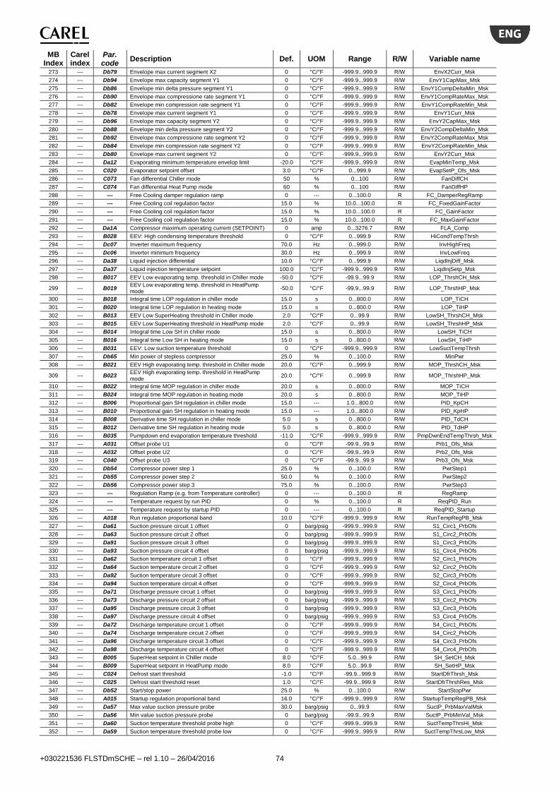
+030221536 FLSTDmSCHE – rel 1.10 – 26/04/2016 74
MB Index
Carel index
Par. code
Description Def. UOM Range R/W Variable name
273 --- Db79 Envelope max current segment X2 0 °C/°F -999.9...999.9 R/W EnvX2Curr_Msk
274 --- Db94 Envelope max capacity segment Y1 0 °C/°F -999.9...999.9 R/W EnvY1CapMax_Msk
275 --- Db86 Envelope min delta pressure segment Y1 0 °C/°F -999.9...999.9 R/W EnvY1CompDeltaMin_Msk
276 --- Db90 Envelope max compressione rate segment Y1 0 °C/°F -999.9...999.9 R/W EnvY1CompRateMax_Msk
277 --- Db82 Envelope min compression rate segment Y1 0 °C/°F -999.9...999.9 R/W EnvY1CompRateMin_Msk
278 --- Db78 Envelope max current segment Y1 0 °C/°F -999.9...999.9 R/W EnvY1Curr_Msk
279 --- Db96 Envelope max capacity segment Y2 0 °C/°F -999.9...999.9 R/W EnvY2CapMax_Msk
280 --- Db88 Envelope min delta pressure segment Y2 0 °C/°F -999.9...999.9 R/W EnvY2CompDeltaMin_Msk
281 --- Db92 Envelope max compressione rate segment Y2 0 °C/°F -999.9...999.9 R/W EnvY2CompRateMax_Msk
282 --- Db84 Envelope min compression rate segment Y2 0 °C/°F -999.9...999.9 R/W EnvY2CompRateMin_Msk
283 --- Db80 Envelope max current segment Y2 0 °C/°F -999.9...999.9 R/W EnvY2Curr_Msk
284 --- Da12 Evaporating minimum temperature envelop limit -20.0 °C/°F -999.9...999.9 R/W EvapMinTemp_Msk
285 --- C020 Evaporator setpoint offset 3.0 °C/°F 0...999.9 R/W EvapSetP_Ofs_Msk
286 --- C073 Fan differential Chiller mode 50 % 0...100 R/W FanDiffCH
287 --- C074 Fan differential Heat Pump mode 60 % 0...100 R/W FanDiffHP
288 --- --- Free Cooling damper regulation ramp 0 --- 0...100.0 R FC_DamperRegRamp
289 --- --- Free Cooling coil regulation factor 15.0 % 10.0...100.0 R FC_FixedGainFactor
290 --- --- Free Cooling coil regulation factor 15.0 % 10.0...100.0 R FC_GainFactor
291 --- --- Free Cooling coil regulation factor 15.0 % 10.0...100.0 R FC_MaxGainFactor
292 --- Da1A Compressor maximum operating current (SETPOINT) 0 amp 0...3276.7 R/W FLA_Comp
293 --- B028 EEV: High condensing temperature threshold 0 °C/°F 0...999.9 R/W HiCondTempThrsh
294 --- Dc07 Inverter maximum frequency 70.0 Hz 0...999.0 R/W InvHighFreq
295 --- Dc06 Inverter minimum frequency 30.0 Hz 0...999.9 R/W InvLowFreq
296 --- Da38 Liquid injection differential 10.0 °C/°F 0...999.9 R/W LiqdInjDiff_Msk
297 --- Da37 Liquid injection temperature setpoint 100.0 °C/°F -999.9...999.9 R/W LiqdInjSetp_Msk
298 --- B017 EEV Low evaporating temp. threshold in Chiller mode -50.0 °C/°F -99.9...99.9 R/W LOP_ThrshCH_Msk
299 --- B019 EEV Low evaporating temp. threshold in HeatPump mode
-50.0 °C/°F -99.9...99.9 R/W LOP_ThrshHP_Msk
300 --- B018 Integral time LOP regulation in chiller mode 15.0 s 0...800.0 R/W LOP_TiCH
301 --- B020 Integral time LOP regulation in heating mode 15.0 s 0...800.0 R/W LOP_TiHP
302 --- B013 EEV Low SuperHeating threshold in Chiller mode 2.0 °C/°F 0...99.9 R/W LowSH_ThrshCH_Msk
303 --- B015 EEV Low SuperHeating threshold in HeatPump mode 2.0 °C/°F 0...99.9 R/W LowSH_ThrshHP_Msk
304 --- B014 Integral time Low SH in chiller mode 15.0 s 0...800.0 R/W LowSH_TiCH
305 --- B016 Integral time Low SH in heating mode 15.0 s 0...800.0 R/W LowSH_TiHP
306 --- B031 EEV: Low suction temperature threshold 0 °C/°F -999.9...999.9 R/W LowSuctTempThrsh
307 --- Db65 Min power of stepless compressor 25.0 % 0...100.0 R/W MinPwr
308 --- B021 EEV High evaporating temp. threshold in Chiller mode 20.0 °C/°F 0...999.9 R/W MOP_ThrshCH_Msk
309 --- B023 EEV High evaporating temp. threshold in HeatPump mode
20.0 °C/°F 0...999.9 R/W MOP_ThrshHP_Msk
310 --- B022 Integral time MOP regulation in chiller mode 20.0 s 0...800.0 R/W MOP_TiCH
311 --- B024 Integral time MOP regulation in heating mode 20.0 s 0...800.0 R/W MOP_TiHP
312 --- B006 Proportional gain SH regulation in chiller mode 15.0 --- 1.0...800.0 R/W PID_KpCH
313 --- B010 Proportional gain SH regulation in heating mode 15.0 --- 1.0...800.0 R/W PID_KpHP
314 --- B008 Derivative time SH regulation in chiller mode 5.0 s 0...800.0 R/W PID_TdCH
315 --- B012 Derivative time SH regulation in heating mode 5.0 s 0...800.0 R/W PID_TdHP
316 --- B035 Pumpdown end evaporation temperature threshold -11.0 °C/°F -999.9...999.9 R/W PmpDwnEndTempThrsh_Msk
317 --- A031 Offset probe U1 0 °C/°F -99.9...99.9 R/W Prb1_Ofs_Msk
318 --- A032 Offset probe U2 0 °C/°F -99.9...99.9 R/W Prb2_Ofs_Msk
319 --- C040 Offset probe U3 0 °C/°F -99.9...99.9 R/W Prb3_Ofs_Msk
320 --- Db54 Compressor power step 1 25.0 % 0...100.0 R/W PwrStep1
321 --- Db55 Compressor power step 2 50.0 % 0...100.0 R/W PwrStep2
322 --- Db56 Compressor power step 3 75.0 % 0...100.0 R/W PwrStep3
323 --- --- Regulation Ramp (e.g. from Temperature controller) 0 --- 0...100.0 R RegRamp
324 --- --- Temperature request by run PID 0 % 0...100.0 R ReqPID_Run
325 --- --- Temperature request by startup PID 0 --- 0...100.0 R ReqPID_Startup
326 --- A018 Run regulation proportional band 10.0 °C/°F -999.9...999.9 R/W RunTempRegPB_Msk
327 --- Da61 Suction pressure circuit 1 offset 0 barg/psig -999.9...999.9 R/W S1_Circ1_PrbOfs
328 --- Da63 Suction pressure circuit 2 offset 0 barg/psig -999.9...999.9 R/W S1_Circ2_PrbOfs
329 --- Da91 Suction pressure circuit 3 offset 0 barg/psig -999.9...999.9 R/W S1_Circ3_PrbOfs
330 --- Da93 Suction pressure circuit 4 offset 0 barg/psig -999.9...999.9 R/W S1_Circ4_PrbOfs
331 --- Da62 Suction temperature circuit 1 offset 0 °C/°F -999.9...999.9 R/W S2_Circ1_PrbOfs
332 --- Da64 Suction temperature circuit 2 offset 0 °C/°F -999.9...999.9 R/W S2_Circ2_PrbOfs
333 --- Da92 Suction temperature circuit 3 offset 0 °C/°F -999.9...999.9 R/W S2_Circ3_PrbOfs
334 --- Da94 Suction temperature circuit 4 offset 0 °C/°F -999.9...999.9 R/W S2_Circ4_PrbOfs
335 --- Da71 Discharge pressure circuit 1 offset 0 barg/psig -999.9...999.9 R/W S3_Circ1_PrbOfs
336 --- Da73 Discharge pressure circuit 2 offset 0 barg/psig -999.9...999.9 R/W S3_Circ2_PrbOfs
337 --- Da95 Discharge pressure circuit 3 offset 0 barg/psig -999.9...999.9 R/W S3_Circ3_PrbOfs
338 --- Da97 Discharge pressure circuit 4 offset 0 barg/psig -999.9...999.9 R/W S3_Circ4_PrbOfs
339 --- Da72 Discharge temperature circuit 1 offset 0 °C/°F -999.9...999.9 R/W S4_Circ1_PrbOfs
340 --- Da74 Discharge temperature circuit 2 offset 0 °C/°F -999.9...999.9 R/W S4_Circ2_PrbOfs
341 --- Da96 Discharge temperature circuit 3 offset 0 °C/°F -999.9...999.9 R/W S4_Circ3_PrbOfs
342 --- Da98 Discharge temperature circuit 4 offset 0 °C/°F -999.9...999.9 R/W S4_Circ4_PrbOfs
343 --- B005 SuperHeat setpoint in Chiller mode 8.0 °C/°F 5.0...99.9 R/W SH_SetCH_Msk
344 --- B009 SuperHeat setpoint in HeatPump mode 8.0 °C/°F 5.0...99.9 R/W SH_SetHP_Msk
345 --- C024 Defrost start threshold -1.0 °C/°F -99.9...999.9 R/W StartDfrThrsh_Msk
346 --- C025 Defrost start threshold reset 1.0 °C/°F -99.9...999.9 R/W StartDfrThrshRes_Msk
347 --- Db52 Start/stop power 25.0 % 0...100.0 R/W StartStopPwr
348 --- A015 Startup regulation proportional band 16.0 °C/°F -999.9...999.9 R/W StartupTempRegPB_Msk
349 --- Da57 Max value suction pressure probe 30.0 barg/psig 0...99.9 R/W SuctP_PrbMaxValMsk
350 --- Da56 Min value suction pressure probe 0 barg/psig -99.9...99.9 R/W SuctP_PrbMinVal_Msk
351 --- Da60 Suction temperature threshold probe high 0 °C/°F -999.9...999.9 R/W SuctTempThrsHi_Msk
352 --- Da59 Suction temperature threshold probe low 0 °C/°F -999.9...999.9 R/W SuctTempThrsLow_Msk
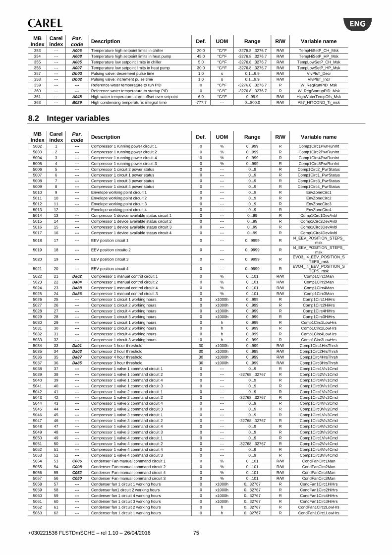
+030221536 FLSTDmSCHE – rel 1.10 – 26/04/2016 75
MB Index
Carel index
Par. code
Description Def. UOM Range R/W Variable name
353 --- A006 Temperature high setpoint limits in chiller 20.0 °C/°F -3276.8...3276.7 R/W TempHiSetP_CH_Msk
354 --- A008 Temperature high setpoint limits in heat pump 45.0 °C/°F -3276.8...3276.7 R/W TempHiSetP_HP_Msk
355 --- A005 Temperature low setpoint limits in chiller 5.0 °C/°F -3276.8...3276.7 R/W TempLowSetP_CH_Msk
356 --- A007 Temperature low setpoint limits in heat pump 30.0 °C/°F -3276.8...3276.7 R/W TempLowSetP_HP_Msk
357 --- Db03 Pulsing valve: decrement pulse time 1.0 s 0.1...9.9 R/W VlvPlsT_Decr
358 --- Db02 Pulsing valve: increment pulse time 1.0 s 0.1...9.9 R/W VlvPlsT_Incr
359 --- --- Reference water temperature to run PID 0 °C/°F -3276.8...3276.7 R W_RegRunPID_Msk
360 --- --- Reference water temperature to startup PID 0 °C/°F -3276.8...3276.7 R W_RegStartupPID_Msk
361 --- A048 High water temperature alarm offset over setpoint 6.0 °C/°F 0..99.9 R/W HighWaterTempOfs_Msk
363 --- B029 High condensing temperature: integral time -777.7 --- 0...800.0 R/W A57_HITCOND_Ti_msk
8.2 Integer variables
MB Index
Carel index
Par. code
Description Def. UOM Range R/W Variable name
5002 1 --- Compressor 1 running power circuit 1 0 % 0...999 R Comp1Circ1PwrRunInt
5003 2 --- Compressor 1 running power circuit 2 0 % 0...999 R Comp1Circ2PwrRunInt
5004 3 --- Compressor 1 running power circuit 4 0 % 0...999 R Comp1Circ4PwrRunInt
5005 4 --- Compressor 1 running power circuit 3 0 % 0...999 R Comp1Circ3PwrRunInt
5006 5 --- Compressor 1 circuit 2 power status 0 --- 0...9 R Comp1Circ2_PwrStatus
5007 6 --- Compressor 1 circuit 1 power status 0 --- 0...9 R Comp1Circ1_PwrStatus
5008 7 --- Compressor 1 circuit 3 power status 0 --- 0...9 R Comp1Circ3_PwrStatus
5009 8 --- Compressor 1 circuit 4 power status 0 --- 0...9 R Comp1Circ4_PwrStatus
5010 9 --- Envelope working point circuit 1 0 --- 0...9 R EnvZoneCirc1
5011 10 --- Envelope working point circuit 2 0 --- 0...9 R EnvZoneCirc2
5012 11 --- Envelope working point circuit 3 0 --- 0...9 R EnvZoneCirc3
5013 12 --- Envelope working point circuit 4 0 --- 0...9 R EnvZoneCirc4
5014 13 --- Compressor 1 device available status circuit 1 0 --- 0...99 R Comp1Circ1DevAvbl
5015 14 --- Compressor 1 device available status circuit 2 0 --- 0...99 R Comp1Circ2DevAvbl
5016 15 --- Compressor 1 device available status circuit 3 0 --- 0...99 R Comp1Circ3DevAvbl
5017 16 --- Compressor 1 device available status circuit 4 0 --- 0...99 R Comp1Circ4DevAvbl
5018 17 --- EEV position circuit 1 0 --- 0...9999 R I4_EEV_POSITION_STEPS_
msk
5019 18 --- EEV position circuito 2 0 --- 0...9999 R I4_EEV_POSITION_STEPS_
msk
5020 19 --- EEV position circuit 3 0 --- 0...9999 R EVO3_I4_EEV_POSITION_S
TEPS_msk
5021 20 --- EEV position circuit 4 0 --- 0...9999 R EVO4_I4_EEV_POSITION_S
TEPS_msk
5022 21 Da02 Compressor 1 manual control circuit 1 0 % 0...101 R/W Comp1Circ1Man
5023 22 Da04 Compressor 1 manual control circuit 2 0 % 0...101 R/W Comp1Circ2Man
5024 23 Da88 Compressor 1 manual control circuit 4 0 % 0...101 R/W Comp1Circ4Man
5025 24 Da86 Compressor 1 manual control circuit 3 0 % 0...101 R/W Comp1Circ3Man
5026 25 --- Compressor 1 circuit 1 working hours 0 x1000h 0...999 R Comp1Circ1HiHrs
5027 26 --- Compressor 1 circuit 2 working hours 0 x1000h 0...999 R Comp1Circ2HiHrs
5028 27 --- Compressor 1 circuit 4 working hours 0 x1000h 0...999 R Comp1Circ4HiHrs
5029 28 --- Compressor 1 circuit 3 working hours 0 x1000h 0...999 R Comp1Circ3HiHrs
5030 29 --- Compressor 1 circuit 1 working hours 0 h 0...999 R Comp1Circ1LowHrs
5031 30 --- Compressor 1 circuit 2 working hours 0 h 0...999 R Comp1Circ2LowHrs
5032 31 --- Compressor 1 circuit 4 working hours 0 h 0...999 R Comp1Circ4LowHrs
5033 32 --- Compressor 1 circuit 3 working hours 0 h 0...999 R Comp1Circ3LowHrs
5034 33 Da01 Compressor 1 hour threshold 30 x1000h 0...999 R/W Comp1Circ1HrsThrsh
5035 34 Da03 Compressor 2 hour threshold 30 x1000h 0...999 R/W Comp1Circ2HrsThrsh
5036 35 Da87 Compressor 4 hour threshold 30 x1000h 0...999 R/W Comp1Circ4HrsThrsh
5037 36 Da85 Compressor 3 hour threshold 30 x1000h 0...999 R/W Comp1Circ3HrsThrsh
5038 37 --- Compressor 1 valve 1 command circuit 1 0 --- 0...9 R Comp1Circ1Vlv1Cmd
5039 38 --- Compressor 1 valve 1 command circuit 2 0 --- -32768...32767 R Comp1Circ2Vlv1Cmd
5040 39 --- Compressor 1 valve 1 command circuit 4 0 --- 0...9 R Comp1Circ4Vlv1Cmd
5041 40 --- Compressor 1 valve 1 command circuit 3 0 --- 0...9 R Comp1Circ3Vlv1Cmd
5042 41 --- Compressor 1 valve 2 command circuit 1 0 --- 0...9 R Comp1Circ1Vlv2Cmd
5043 42 --- Compressor 1 valve 2 command circuit 2 0 --- -32768...32767 R Comp1Circ2Vlv2Cmd
5044 43 --- Compressor 1 valve 2 command circuit 4 0 --- 0...9 R Comp1Circ4Vlv2Cmd
5045 44 --- Compressor 1 valve 2 command circuit 3 0 --- 0...9 R Comp1Circ3Vlv2Cmd
5046 45 --- Compressor 1 valve 3 command circuit 1 0 --- 0...9 R Comp1Circ1Vlv3Cmd
5047 46 --- Compressor 1 valve 3 command circuit 2 0 --- -32768...32767 R Comp1Circ2Vlv3Cmd
5048 47 --- Compressor 1 valve 3 command circuit 4 0 --- 0...9 R Comp1Circ4Vlv3Cmd
5049 48 --- Compressor 1 valve 3 command circuit 3 0 --- 0...9 R Comp1Circ3Vlv3Cmd
5050 49 --- Compressor 1 valve 4 command circuit 1 0 --- 0...9 R Comp1Circ1Vlv4Cmd
5051 50 --- Compressor 1 valve 4 command circuit 2 0 --- -32768...32767 R Comp1Circ2Vlv4Cmd
5052 51 --- Compressor 1 valve 4 command circuit 4 0 --- 0...9 R Comp1Circ4Vlv4Cmd
5053 52 --- Compressor 1 valve 4 command circuit 3 0 --- 0...9 R Comp1Circ3Vlv4Cmd
5054 53 C006 Condenser Fan manual command circuit 1 0 % 0...101 R/W CondFanCirc1Man
5055 54 C008 Condenser Fan manual command circuit 2 0 % 0...101 R/W CondFanCirc2Man
5056 55 C052 Condenser Fan manual command circuit 4 0 % 0...101 R/W CondFanCirc4Man
5057 56 C050 Condenser Fan manual command circuit 3 0 % 0...101 R/W CondFanCirc3Man
5058 57 --- Condenser fan 1 circuit 1 working hours 0 x1000h 0...32767 R CondFan1Circ1HiHrs
5059 58 --- Condenser fan1 circuit 2 working hours 0 x1000h 0...32767 R CondFan1Circ2HiHrs
5060 59 --- Condenser fan 1 circuit 4 working hours 0 x1000h 0...32767 R CondFan1Circ4HiHrs
5061 60 --- Condenser fan 1 circuit 3 working hours 0 x1000h 0...32767 R CondFan1Circ3HiHrs
5062 61 --- Condenser fan 1 circuit 2 working hours 0 h 0...32767 R CondFan1Circ2LowHrs
5063 62 --- Condenser fan 1 circuit 1 working hours 0 h 0...32767 R CondFan1Circ1LowHrs

+030221536 FLSTDmSCHE – rel 1.10 – 26/04/2016 76
MB Index
Carel index
Par. code
Description Def. UOM Range R/W Variable name
5064 63 --- Condenser fan 1 circuit 4 working hours 0 h 0...32767 R CondFan1Circ4LowHrs
5065 64 --- Condenser fan 1 circuit 3 working hours 0 h 0...32767 R CondFan1Circ3LowHrs
5066 65 C005 Circuit 1 condenser fan 1 maintenance hour threshold 99 x1000h 0...999 R/W CondFan1Circ1HrsThrsh
5067 66 C007 Circuit 2 condenser fan 1 maintenance hour threshold 99 x1000h 0...999 R/W CondFan1Circ2HrsThrsh
5068 67 C051 Circuit 4 condenser fan 1 maintenance hour threshold 99 x1000h 0...999 R/W CondFan1Circ4HrsThrsh
5069 68 C049 Circuit 3 condenser fan1 maintenance hour threshold 99 x1000h 0...999 R/W CondFan1Circ3HrsThrsh
5070 69 C053 Condenser Fan 1 manual command circuit 1 0 --- 0...2 R/W CondFan1Circ1Man
5071 70 C058 Condenser Fan 1 manual command circuit 2 0 --- 0...2 R/W CondFan1Circ2Man
5072 71 C063 Condenser Fan 1 manual command circuit 3 0 --- 0...2 R/W CondFan1Circ3Man
5073 72 C068 Condenser Fan 1 manual command circuit 4 0 --- 0...2 R/W CondFan1Circ4Man
5074 73 C055 Condenser Fan 2 manual command circuit 1 0 --- 0...2 R/W CondFan2Circ1Man
5075 74 C060 Condenser Fan 2 manual command circuit 2 0 --- 0...2 R/W CondFan2Circ2Man
5076 75 C065 Condenser Fan 2 manual command circuit 3 0 --- 0...2 R/W CondFan2Circ3Man
5077 76 C070 Condenser Fan 2 manual command circuit 4 0 --- 0...2 R/W CondFan2Circ4Man
5078 77 --- Condenser fan 2 circuit 1 working hours 0 x1000h 0...32767 R CondFan2Circ1HiHrs
5079 78 --- Condenser fan 2 circuit 2 working hours 0 x1000h 0...32767 R CondFan2Circ2HiHrs
5080 79 --- Condenser fan 2 circuit 3 working hours 0 x1000h 0...32767 R CondFan2Circ3HiHrs
5081 80 --- Condenser fan 2 circuit 4 working hours 0 x1000h 0...32767 R CondFan2Circ4HiHrs
5082 81 --- Condenser fan 2 circuit 1 working hours 0 h 0...32767 R CondFan2Circ1LowHrs
5083 82 --- Condenser fan 2 circuit 2 working hours 0 h 0...32767 R CondFan2Circ2LowHrs
5084 83 --- Condenser fan 2 circuit 3 working hours 0 h 0...32767 R CondFan2Circ3LowHrs
5085 84 --- Condenser fan 2 circuit 4 working hours 0 h 0...32767 R CondFan2Circ4LowHrs
5086 85 C054 Circuit 1 condenser fan 2 maintenance hour threshold 99 x1000h 0...999 R/W CondFan2Circ1HrsThrsh
5087 86 C059 Circuit 2 condenser fan 2 maintenance hour threshold 99 x1000h 0...999 R/W CondFan2Circ2HrsThrsh
5088 87 C064 Circuit 3 condenser fan 2 maintenance hour threshold 99 x1000h 0...999 R/W CondFan2Circ3HrsThrsh
5089 88 C069 Circuit 4 condenser fan 2 maintenance hour threshold 99 x1000h 0...999 R/W CondFan2Circ4HrsThrsh
5090 89 C057 Condenser Fan 3 manual command circuit 1 0 --- 0...2 R/W CondFan3Circ1Man
5091 90 C062 Condenser Fan 3 manual command circuit 2 0 --- 0...2 R/W CondFan3Circ2Man
5092 91 C067 Condenser Fan 3 manual command circuit 3 0 --- 0...2 R/W CondFan3Circ3Man
5093 92 C072 Condenser Fan 3 manual command circuit 4 0 --- 0...2 R/W CondFan3Circ4Man
5094 93 --- Condenser fan 3 circuit 1 working hours 0 x1000h 0...32767 R CondFan3Circ1HiHrs
5095 94 --- Condenser fan 3 circuit 2 working hours 0 x1000h 0...32767 R CondFan3Circ2HiHrs
5096 95 --- Condenser fan 3 circuit 3 working hours 0 x1000h 0...32767 R CondFan3Circ3HiHrs
5097 96 --- Condenser fan 3 circuit 4 working hours 0 x1000h 0...32767 R CondFan3Circ4HiHrs
5098 97 --- Condenser fan 3 circuit 1 working hours 0 h 0...32767 R CondFan3Circ1LowHrs
5099 98 --- Condenser fan 3 circuit 2 working hours 0 h 0...32767 R CondFan3Circ2LowHrs
5100 99 --- Condenser fan 3 circuit 3 working hours 0 h 0...32767 R CondFan3Circ3LowHrs
5101 100 --- Condenser fan 3 circuit 4 working hours 0 h 0...32767 R CondFan3Circ4LowHrs
5102 101 C056 Circuit 1 condenser fan 3 maintenance hour threshold 99 x1000h 0...999 R/W CondFan3Circ1HrsThrsh
5103 102 C061 Circuit 2 condenser fan 3 maintenance hour threshold 99 x1000h 0...999 R/W CondFan3Circ2HrsThrsh
5104 103 C066 Circuit 3 condenser fan 3 maintenance hour threshold 99 x1000h 0...999 R/W CondFan3Circ3HrsThrsh
5105 104 C071 Circuit 4 condenser fan 3 maintenance hour threshold 99 x1000h 0...999 R/W CondFan3Circ4HrsThrsh
5106 105 A002 Evaporator pump in manual mode 0 --- 0...2 R/W EvapPmpMan
5107 106 --- Evaporator pump 1 working hours 0 x1000h 0...32767 R EvapPmp1HiHrs
5108 107 --- Evaporator pump 1 working hours 0 h 0...32767 R EvapPmp1LowHrs
5109 108 A001 Evaporator pump 1 maintenance hour threshold 99 x1000h 0...999 R/W EvapPmp1HrsThrsh
5110 109 --- Evaporator pump 2 working hours 0 x1000h 0...32767 R EvapPmp2HiHrs
5111 110 --- Evaporator pump 2 working hours 0 h 0...32767 R EvapPmp2LowHrs
5112 111 A003 Evaporator pump 2 maintenance hour threshold 99 x1000h 0...999 R/W EvapPmp2HrsThrsh
5113 112 C002 Condenser pump in manual mode 0 --- 0...2 R/W CondPmpMan
5114 113 --- Condenser pump 1 working hours 0 x1000h 0...32767 R CondPmp1HiHrs
5115 114 --- Condenser pump 1 working hours 0 h 0...32767 R CondPmp1LowHrs
5116 115 C001 Condenser pump 1 maintenance hour threshold 99 x1000h 0...999 R/W CondPmp1HrsThrsh
5117 116 --- Condenser pump 2 working hours 0 x1000h 0...32767 R CondPmp2HiHrs
5118 117 --- Condenser pump 2 working hours 0 h 0...32767 R CondPmp2LowHrs
5119 118 C003 Condenser pump 2 maintenance hour threshold 99 x1000h 0...999 R/W CondPmp2HrsThrsh
5120 119 --- BMS software version (include the SwVerX and SwVerY)
15018 --- 0...32767 R BMS_SW_Ver_XY
5121 120 --- BMS software version (include the SwVerZ) 15018 --- 0...32767 R BMS_SW_Ver_Z
5122 121 --- BMS software date 15018 --- 0...32767 R BMS_SW_Date
5123 122 Q008 Clock hour for BMS 0 --- 0...23 R/W BMSHour
5124 123 Q009 Clock minute for BMS 0 --- 0...59 R/W BMSMinute
5125 124 Q005 Day for BMS 0 --- 1...31 R/W BMSDay
5126 125 Q006 Month for BMS 0 --- 1...12 R/W BMSMonth
5127 126 Q007 Year for BMS 0 --- 0...99 R/W BMSYear
5128 127 --- Actual phase run of compressor 1 circuit 1 0 --- 0...30 R ServiceTool_Comp1Circ1Pha
seRun
5129 128 --- Actual phase run of compressor 1 circuit 2 0 --- 0...30 R ServiceTool_Comp1Circ2Pha
seRun
5130 129 --- Actual phase run of compressor 1 circuit 3 0 --- 0...30 R ServiceTool_Comp1Circ3Pha
seRun
5131 130 --- Actual phase run of compressor 1 circuit 4 0 --- 0...30 R ServiceTool_Comp1Circ4Pha
seRun
5132 131 --- Temperature value converted 0 °C/°F -999...999 R Temp_X0_Circ1
5133 132 --- Temperature value converted 0 °C/°F -999...999 R Temp_X1_Circ1
5134 133 --- Temperature value converted 0 °C/°F -999...999 R Temp_X2_Circ1
5135 134 --- Temperature value converted 0 °C/°F -999...999 R Temp_X3_Circ1
5136 135 --- Temperature value converted 0 °C/°F -999...999 R Temp_X4_Circ1
5137 136 --- Temperature value converted 0 °C/°F -999...999 R Temp_X5_Circ1
5138 137 --- Temperature value converted 0 °C/°F -999...999 R Temp_X6_Circ1
5139 138 --- Temperature value converted 0 °C/°F -999...999 R Temp_X7_Circ1
5140 139 --- Temperature value converted 0 °C/°F -999...999 R Temp_Y0_Circ1
5141 140 --- Temperature value converted 0 °C/°F -999...999 R Temp_Y1_Circ1

+030221536 FLSTDmSCHE – rel 1.10 – 26/04/2016 77
MB Index
Carel index
Par. code
Description Def. UOM Range R/W Variable name
5142 141 --- Temperature value converted 0 °C/°F -999...999 R Temp_Y3_Circ1
5143 142 --- Temperature value converted 0 °C/°F -999...999 R Temp_Y2_Circ1
5144 143 --- Temperature value converted 0 °C/°F -999...999 R Temp_Y4_Circ1
5145 144 --- Temperature value converted 0 °C/°F -999...999 R Temp_Y5_Circ1
5146 145 --- Temperature value converted 0 °C/°F -999...999 R Temp_Y6_Circ1
5147 146 --- Temperature value converted 0 °C/°F -999...999 R Temp_Y7_Circ1
5148 147 --- Temperature value converted 0 °C/°F -999...999 R Temp_X0_Circ2
5149 148 --- Temperature value converted 0 °C/°F -999...999 R Temp_X1_Circ2
5150 149 --- Temperature value converted 0 °C/°F -999...999 R Temp_X2_Circ2
5151 150 --- Temperature value converted 0 °C/°F -999...999 R Temp_X3_Circ2
5152 151 --- Temperature value converted 0 °C/°F -999...999 R Temp_X4_Circ2
5153 152 --- Temperature value converted 0 °C/°F -999...999 R Temp_X5_Circ2
5154 153 --- Temperature value converted 0 °C/°F -999...999 R Temp_X6_Circ2
5155 154 --- Temperature value converted 0 °C/°F -999...999 R Temp_X7_Circ2
5156 155 --- Temperature value converted 0 °C/°F -999...999 R Temp_Y0_Circ2
5157 156 --- Temperature value converted 0 °C/°F -999...999 R Temp_Y1_Circ2
5158 157 --- Temperature value converted 0 °C/°F -999...999 R Temp_Y2_Circ2
5159 158 --- Temperature value converted 0 °C/°F -999...999 R Temp_Y3_Circ2
5160 159 --- Temperature value converted 0 °C/°F -999...999 R Temp_Y4_Circ2
5161 160 --- Temperature value converted 0 °C/°F -999...999 R Temp_Y5_Circ2
5162 161 --- Temperature value converted 0 °C/°F -999...999 R Temp_Y6_Circ2
5163 162 --- Temperature value converted 0 °C/°F -999...999 R Temp_Y7_Circ2
5164 163 --- Temperature value converted 0 °C/°F -999...999 R Temp_X0_Circ3
5165 164 --- Temperature value converted 0 °C/°F -999...999 R Temp_X1_Circ3
5166 165 --- Temperature value converted 0 °C/°F -999...999 R Temp_X2_Circ3
5167 166 --- Temperature value converted 0 °C/°F -999...999 R Temp_X3_Circ3
5168 167 --- Temperature value converted 0 °C/°F -999...999 R Temp_X4_Circ3
5169 168 --- Temperature value converted 0 °C/°F -999...999 R Temp_X5_Circ3
5170 169 --- Temperature value converted 0 °C/°F -999...999 R Temp_X6_Circ3
5171 170 --- Temperature value converted 0 °C/°F -999...999 R Temp_X7_Circ3
5172 171 --- Temperature value converted 0 °C/°F -999...999 R Temp_X0_Circ4
5173 172 --- Temperature value converted 0 °C/°F -999...999 R Temp_X2_Circ4
5174 173 --- Temperature value converted 0 °C/°F -999...999 R Temp_X1_Circ4
5175 174 --- Temperature value converted 0 °C/°F -999...999 R Temp_X3_Circ4
5176 175 --- Temperature value converted 0 °C/°F -999...999 R Temp_X4_Circ4
5177 176 --- Temperature value converted 0 °C/°F -999...999 R Temp_X5_Circ4
5178 177 --- Temperature value converted 0 °C/°F -999...999 R Temp_X6_Circ4
5179 178 --- Temperature value converted 0 °C/°F -999...999 R Temp_X7_Circ4
5180 179 --- Temperature value converted 0 °C/°F -999...999 R Temp_Y0_Circ3
5181 180 --- Temperature value converted 0 °C/°F -999...999 R Temp_Y1_Circ3
5182 181 --- Temperature value converted 0 °C/°F -999...999 R Temp_Y2_Circ3
5183 182 --- Temperature value converted 0 °C/°F -999...999 R Temp_Y3_Circ3
5184 183 --- Temperature value converted 0 °C/°F -999...999 R Temp_Y5_Circ3
5185 184 --- Temperature value converted 0 °C/°F -999...999 R Temp_Y4_Circ3
5186 185 --- Temperature value converted 0 °C/°F -999...999 R Temp_Y7_Circ3
5187 186 --- Temperature value converted 0 °C/°F -999...999 R Temp_Y6_Circ3
5188 187 --- Temperature value converted 0 °C/°F -999...999 R Temp_Y0_Circ4
5189 188 --- Temperature value converted 0 °C/°F -999...999 R Temp_Y1_Circ4
5190 189 --- Temperature value converted 0 °C/°F -999...999 R Temp_Y2_Circ4
5191 190 --- Temperature value converted 0 °C/°F -999...999 R Temp_Y4_Circ4
5192 191 --- Temperature value converted 0 °C/°F -999...999 R Temp_Y3_Circ4
5193 192 --- Temperature value converted 0 °C/°F -999...999 R Temp_Y5_Circ4
5194 193 --- Temperature value converted 0 °C/°F -999...999 R Temp_Y6_Circ4
5195 194 --- Temperature value converted 0 °C/°F -999...999 R Temp_Y7_Circ4
5209 --- E006 BMS address 1 --- 0...207 R/W Adress_BMS
5210 --- E009 BMS2 address 1 --- 0...207 R/W Adress_BMS2
5211 --- --- Antifreeze heater output channel 0 --- 0...99 R AFreezeHeatPos
5212 --- A041 Antifreeze management 0 --- 0...2 R/W AFreezeMng
5213 --- C039 Antifreeze condenser alarm delay time at 1K below thrsh
60 s 5...300 R/W Al_FreezeCondT_1K
5214 --- A030 Antifreeze alarm delay time at 1K below thrsh 60 s 5...300 R/W Al_FreezeT_1K
5215 --- E015 Analogue output test channel 1 --- 0...6 R/W AOut_TestPos
5216 --- E005 BMS speed 4 --- 0...4 R/W Baudrate_BMS
5217 --- E008 BMS2 baudrate 4 --- 0...4 R/W Baudrate_BMS2
5218 --- Da77 Number of circuit in the unit 1 --- 1...4 R/W CircNo
5219 --- --- Position Compressor 1 circuit 1 direct start 0 --- 0...99 R Comp1Circ1DeltaPwA_Direct
Pos
5220 --- --- Reset Inverter alarms compressor 1 circuit 1 0 --- 0...32767 R Comp1Circ1InvAlrmResPos
5221 --- --- Emergency shutdown Inverter compressor 1 circuit 1 0 --- 0...32767 R Comp1Circ1InvEmergShOffP
os
5222 --- --- Start signal Inverter compressor 1 circuit 1 0 --- 0...32767 R Comp1Circ1InvStartPos
5223 --- --- Compressor 1 running phase circuit 1 0 --- 0...99 R Comp1Circ1PhaseRun
5224 --- --- Rotation request compressor 1 circuit 1 0 % 0...999 R Comp1Circ1RotInt
5225 --- --- Position Compressor 1 circuit 1 start or PartWinding B 0 --- 0...99 R Comp1Circ1StarPwB_Pos
5226 --- --- Position Compressor 1 valve 1 circuit 1 0 --- 0...99 R Comp1Circ1Vlv1Pos
5227 --- --- Position Compressor 1 valve 2 circuit 1 0 --- 0...99 R Comp1Circ1Vlv2Pos
5228 --- --- Position Compressor 1 valve 3 circuit 1 0 --- 0...99 R Comp1Circ1Vlv3Pos
5229 --- --- Position Compressor 1 valve 4 circuit 1 0 --- 0...99 R Comp1Circ1Vlv4Pos
5230 --- --- Position Compressor 1 circuit 2 direct start 0 --- 0...99 R Comp1Circ2DeltaPwA_Direct
Pos
5231 --- --- Reset Inverter alarms compressor 1 circuit 2 0 --- 0...32767 R Comp1Circ2InvAlrmResPos
5232 --- --- Emergency shutdown Inverter compressor 1 circuit 2 0 --- 0...32767 R Comp1Circ2InvEmergShOffP
os
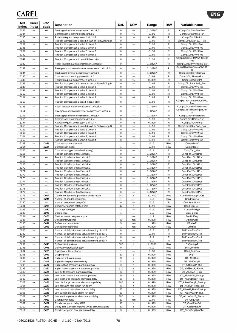
+030221536 FLSTDmSCHE – rel 1.10 – 26/04/2016 78
MB Index
Carel index
Par. code
Description Def. UOM Range R/W Variable name
5233 --- --- Start signal Inverter compressor 1 circuit 2 0 --- 0...32767 R Comp1Circ2InvStartPos
5234 --- --- Compressor 1 running phase circuit 2 0 % 0...99 R Comp1Circ2PhaseRun
5235 --- --- Rotation request compressor 1 circuit 2 0 % 0...999 R Comp1Circ2RotInt
5236 --- --- Position Compressor 1 circuit 2 start or PartWinding B 0 --- 0...99 R Comp1Circ2StarPwB_Pos
5237 --- --- Position Compressor 1 valve 1 circuit 2 0 --- 0...99 R Comp1Circ2Vlv1Pos
5238 --- --- Position Compressor 1 valve 2 circuit 2 0 --- 0...99 R Comp1Circ2Vlv2Pos
5239 --- --- Position Compressor 1 valve 3 circuit 2 0 --- 0...99 R Comp1Circ2Vlv3Pos
5240 --- --- Position Compressor 1 valve 4 circuit 2 0 --- 0...99 R Comp1Circ2Vlv4Pos
5241 --- --- Position Compressor 1 circuit 3 direct start 0 --- 0...99 R Comp1Circ3DeltaPwA_Direct
Pos
5242 --- --- Reset Inverter alarms compressor 1 circuit 3 0 --- 0...32767 R Comp1Circ3InvAlrmResPos
5243 --- --- Emergency shutdown Inverter compressor 1 circuit 3 0 --- 0...32767 R Comp1Circ3InvEmergShOffP
os
5244 --- --- Start signal Inverter compressor 1 circuit 3 0 --- 0...32767 R Comp1Circ3InvStartPos
5245 --- --- Compressor 1 running phase circuit 3 0 --- 0...99 R Comp1Circ3PhaseRun
5246 --- --- Rotation request compressor 1 circuit 3 0 % 0...999 R Comp1Circ3RotInt
5247 --- --- Position Compressor 1 circuit 3 start or PartWinding B 0 --- 0...99 R Comp1Circ3StarPwB_Pos
5248 --- --- Position Compressor 1 valve 1 circuit 3 0 --- 0...99 R Comp1Circ3Vlv1Pos
5249 --- --- Position Compressor 1 valve 2 circuit 3 0 --- 0...99 R Comp1Circ3Vlv2Pos
5250 --- --- Position Compressor 1 valve 3 circuit 3 0 --- 0...99 R Comp1Circ3Vlv3Pos
5251 --- --- Position Compressor 1 valve 4 circuit 3 0 --- 0...99 R Comp1Circ3Vlv4Pos
5252 --- --- Position Compressor 1 circuit 4 direct start 0 --- 0...99 R Comp1Circ4DeltaPwA_Direct
Pos
5253 --- --- Reset Inverter alarms compressor 1 circuit 4 0 --- 0...32767 R Comp1Circ4InvAlrmResPos
5254 --- --- Emergency shutdown Inverter compressor 1 circuit 4 0 --- 0...32767 R Comp1Circ4InvEmergShOffP
os
5255 --- --- Start signal Inverter compressor 1 circuit 4 0 --- 0...32767 R Comp1Circ4InvStartPos
5256 --- --- Compressor 1 running phase circuit 4 0 --- 0...99 R Comp1Circ4PhaseRun
5257 --- --- Rotation request compressor 1 circuit 4 0 % 0...999 R Comp1Circ4RotInt
5258 --- --- Position Compressor 1 circuit 4 start or PartWinding B 0 --- 0...99 R Comp1Circ4StarPwB_Pos
5259 --- --- Position Compressor 1 valve 1 circuit 4 0 --- 0...99 R Comp1Circ4Vlv1Pos
5260 --- --- Position Compressor 1 valve 2 circuit 4 0 --- 0...99 R Comp1Circ4Vlv2Pos
5261 --- --- Position Compressor 1 valve 3 circuit 4 0 --- 0...99 R Comp1Circ4Vlv3Pos
5262 --- --- Position Compressor 1 valve 4 circuit 4 0 --- 0...99 R Comp1Circ4Vlv4Pos
5263 --- Da83 Compressor manufacturer 1 --- 0...5 R/W CompManuf
5264 --- Da84 Compressor model 1 --- 0...99 R/W CompModel
5265 --- --- Compressor type (visualization only) 0 --- 0...9 R CompTyp_Msk
5266 --- --- Position Condenser fan 1 circuit 1 0 --- 0...32767 R CondFan1Circ1Pos
5267 --- --- Position Condenser fan 1 circuit 2 0 --- 0...32767 R CondFan1Circ2Pos
5268 --- --- Position Condenser fan 1 circuit 3 0 --- 0...32767 R CondFan1Circ3Pos
5269 --- --- Position Condenser fan 1 circuit 4 0 --- 0...32767 R CondFan1Circ4Pos
5270 --- --- Position Condenser fan 2 circuit 1 0 --- 0...32767 R CondFan2Circ1Pos
5271 --- --- Position Condenser fan 2 circuit 2 0 --- 0...32767 R CondFan2Circ2Pos
5272 --- --- Position Condenser fan 2 circuit 3 0 --- 0...32767 R CondFan2Circ3Pos
5273 --- --- Position Condenser fan 2 circuit 4 0 --- 0...32767 R CondFan2Circ4Pos
5274 --- --- Position Condenser fan 3 circuit 1 0 --- 0...32767 R CondFan3Circ1Pos
5275 --- --- Position Condenser fan 3 circuit 2 0 --- 0...32767 R CondFan3Circ2Pos
5276 --- --- Position Condenser fan 3 circuit 3 0 --- 0...32767 R CondFan3Circ3Pos
5277 --- --- Position Condenser fan 3 circuit 4 0 --- 0...32767 R CondFan3Circ4Pos
5278 --- C017 Condenser fan startup delay in chiller mode 240 s 30...600 R/W CondFanStartupT_CH
5279 --- C045 Number of condenser pumps 1 --- 1...2 R/W CondPmpNo
5280 --- --- Number condenser pump On 0 --- 0...9 R CondPmpNoOn
5281 --- C013 Condenser pumps rotation time 12 h 1...99 R/W CondPmpRotT
5282 --- Da50 Current probe type 2 --- 0...5 R/W CurrentPrbTyp
5283 --- E003 Date format 1 --- 1...3 R/W DateFormat
5284 --- Da76 Devices unload sequence type 1 --- 1...2 R/W DevUnlSeq
5285 --- C035 Defrost interval time 20 min 0...999 R/W DfrIntervalT
5286 --- C032 Defrost maximum time 5 min 1...999 R/W DfrMaxT
5287 --- C031 Defrost minimum time 1 min 0...999 R/W DfrMinT
5288 --- --- Number of defrost phase actually running circuit 1 0 --- 0...9 R DfrPhaseRunCirc1
5289 --- --- Number of defrost phase actually running circuit 2 0 --- 0...99 R DfrPhaseRunCirc2
5290 --- --- Number of defrost phase actually running circuit 3 0 --- 0...9 R DfrPhaseRunCirc3
5291 --- --- Number of defrost phase actually running circuit 4 0 --- 0...9 R DfrPhaseRunCirc4
5292 --- C030 Defrost startup delay 300 s 1...9999 R/W DfrStartupT
5293 --- C036 Defrost syncronization type 0 --- 0...2 R/W DfrSynchTyp
5294 --- E013 Digital output test channel 1 --- 0...30 R/W DOut_TestPos
5295 --- C033 Dripping time 30 s 0...999 R/W DripT
5296 --- Da19 High current alarm delay 20 s 0...999 R/W DT_AlHiCurr
5297 --- Da18 High discharge pressure delay 40 s 0...999 R/W DT_AlHiDscgP
5298 --- Da21 High suction pressure alarm run delay 60 s 0...999 R/W DT_AlHiSuctP_Run
5299 --- Da20 High suction pressure alarm startup delay 120 s 0...999 R/W DT_AlHiSuctP_Startup
5300 --- Da25 Low delta pressure alarm run delay 20 s 0...999 R/W DT_AlLowDP_Run
5301 --- Da24 Low delta pressure alarm startup delay 45 s 0...999 R/W DT_AlLowDP_Startup
5302 --- Da27 Low discharge pressure alarm run delay 60 s 0...999 R/W DT_AlLowDscgP_Run
5303 --- Da26 Low discharge pressure alarm startup delay 180 s 0...999 R/W DT_AlLowDscgP_Startup
5304 --- Da23 Low pressure ratio alarm run delay 20 s 0...999 R/W DT_AlLowP_RatioRun
5305 --- Da22 Low pressure ratio alarm startup delay 60 s 0...999 R/W DT_AlLowP_RatioStartup
5306 --- Da29 Low suction pressure alarm run delay 60 s 0...999 R/W DT_AlLowSuctP_Run
5307 --- Da28 Low suction pressure alarm startup delay 180 s 0...999 R/W DT_AlLowSuctP_Startup
5308 --- A010 Changeover delay 60 min 0...99 R/W DT_ChgOver
5309 --- C012 Condenser pump delay OFF 10 s 0...999 R/W DT_CondPmpOff
5310 --- C011 Delay from Condenser pump ON to start regulation 30 s 0...999 R/W DT_CondPmpOn
5311 --- C010 Condenser pump flow alarm run delay 3 s 0...999 R/W DT_CondPmpRunFlw

+030221536 FLSTDmSCHE – rel 1.10 – 26/04/2016 79
MB Index
Carel index
Par. code
Description Def. UOM Range R/W Variable name
5312 --- C009 Condenser pump flow alarm startup delay 15 s 0...999 R/W DT_CondPmpStartUpFlw
5313 --- A024 Evaporator pump delay OFF 10 s 0...999 R/W DT_EvapPmpOff
5314 --- A023 Delay from evaporator pump ON to start regulation 60 s 0...999 R/W DT_EvapPmpOn
5315 --- A022 Evaporator pump flow alarm run delay 2 s 0...999 R/W DT_EvapPmpRunFlw
5316 --- A021 Evaporator pump flow alarm startup delay 20 s 0...999 R/W DT_EvapPmpStartUpFlw
5317 --- Da15 Low pressure alarm run delay 10 s 0...999 R/W DT_LP_PstatRun
5318 --- Da14 Low pressure alarm startup delay 40 s 0...999 R/W DT_LP_PstatStartUp
5319 --- Da17 Oil level alarm run delay 15 s 0...999 R/W DT_OilLevRun
5320 --- Da16 Oil level alarm startup delay 30 s 0...999 R/W DT_OilLevStartUp
5321 --- A012 Startup PID --> Run PID delay 180 s 0...9999 R/W DT_StartupRunPID
5322 --- Db57 Step 1 - Step 2 delay 10 s 0...9999 R/W DTStep1Step2
5323 --- Db58 Step 2 - Step 3 delay 10 s 0...9999 R/W DTStep2Step3
5324 --- Db59 Step 3 - Step 4 delay 10 s 0...9999 R/W DTStep3Step4
5325 --- --- Position Eco compressor 1 circuit 1 0 --- 0...99 R EcoComp1Circ1Pos
5326 --- --- Position Eco compressor 1 circuit 2 0 --- 0...99 R EcoComp1Circ2Pos
5327 --- --- Position Eco compressor 1 circuit 3 0 --- 0...99 R EcoComp1Circ3Pos
5328 --- --- Position Eco compressor 1 circuit 4 0 --- 0...99 R EcoComp1Circ4Pos
5329 --- --- Position Digital output value of evaporator pump 1 0 --- 0...99 R EvapPmp1Pos
5330 --- --- Position Digital output value of evaporator pump 2 0 --- 0...99 R EvapPmp2Pos
5331 --- A043 Number of evaporator pumps 1 --- 1...2 R/W EvapPmpNo
5332 --- --- Number evaporator pump On 0 --- 0...9 R EvapPmpNoOn
5333 --- A025 Evaporator pumps rotation time 12 h 0...99 R/W EvapPmpRotT
5334 --- B056 Manual valve position - Circ3 0 --- 0...9999 R/W EVO3_I39_MANUAL_POSIT_
STEPS
5335 --- --- EVD status circuit 3 0 --- 1...100 R EVO3_I8_REG_STATUS_ms
k
5336 --- B058 Manual valve position - Circ4 0 --- 0...9999 R/W EVO4_I39_MANUAL_POSIT_
STEPS
5337 --- --- EVD status circuit 4 0 --- 1...100 R EVO4_I8_REG_STATUS_ms
k
5338 --- Da11 Force rotation interval time 2 h 0...9 R/W FrcRotT
5339 --- --- Position General alarm 0 --- 0...32767 R GenAlrmPos
5340 --- Da42 Ignition type 1 --- 0...2 R/W IgnitionTyp
5341 --- Da10 Compressor load down time 30 s 0...999 R/W LdDwnT
5342 --- Da99 Delay between steps activation 20 s 0...999 R/W LdStepsDT
5343 --- Da09 Compressor load up time 300 s 0...999 R/W LdUpT
5344 --- --- Position Liquid injection compressor 1 circuit 1 0 --- 0...99 R LiqdInjComp1Circ1Pos
5345 --- --- Position Liquid injection compressor 1 circuit 2 0 --- 0...99 R LiqdInjComp1Circ2Pos
5346 --- --- Position Liquid injection compressor 1 circuit 3 0 --- 0...99 R LiqdInjComp1Circ3Pos
5347 --- --- Position Liquid injection compressor 1 circuit 4 0 --- 0...99 R LiqdInjComp1Circ4Pos
5348 --- Db67 Max power reach time for stepless control 60 s 0...9999 R/W MaxPwrDT
5349 --- Da30 Max retry per hour for low suction pressur alarm 3 --- 1...9 R/W MaxRetryAlLowSuctP
5350 --- Db68 MinInputValue of Min time OFF compressor 60 s 0...32767 R/W MinMinOffT
5351 --- Db70 MinInputValue of Min time between ON of the same compressor
360 s 0...32767 R/W MinMinOnOnSameT
5352 --- Db69 MinInputValue of Min time ON compressor 240 s 0...32767 R/W MinMinOnT
5353 --- Da06 Min time OFF compressor after alarm 180 s 0...9999 R/W MinOffAlrmT
5354 --- Da05 Min time OFF compressor 180 s 0...9999 R/W MinOffRegT
5355 --- Da08 Min time between ON of the same compressor 600 s 0...9999 R/W MinOnOnSameT
5356 --- Da07 Min time ON compressor 300 s 0...9999 R/W MinOnT
5357 --- Db66 Min power reach time for stepless control 60 s 0...9999 R/W MinPwrDT
5358 --- C075 Fans number 1 --- 1...3 R/W N_Fans
5359 --- Db10 Compressor OFF: Valve 1 command type 1 --- 0...5 R/W OffCmdVlv1
5360 --- Db20 Compressor OFF: Valve 2 command type 1 --- 0...5 R/W OffCmdVlv2
5361 --- Db30 Compressor OFF: Valve 3 command type 1 --- 0...5 R/W OffCmdVlv3
5362 --- Db40 Compressor OFF: Valve 4 command type 1 --- 0...5 R/W OffCmdVlv4
5363 --- Db13 Compressor phase 1: Valve 1 command type 1 --- 0...5 R/W Phase1CmdVlv1
5364 --- Db23 Compressor phase 1: Valve 2 command type 1 --- 0...5 R/W Phase1CmdVlv2
5365 --- Db33 Compressor phase 1: Valve 3 command type 1 --- 0...5 R/W Phase1CmdVlv3
5366 --- Db43 Compressor phase 1: Valve 4 command type 1 --- 0...5 R/W Phase1CmdVlv4
5367 --- Db14 Compressor phase 2: Valve 1 command type 1 --- 0...5 R/W Phase2CmdVlv1
5368 --- Db24 Compressor phase 2: Valve 2 command type 1 --- 0...5 R/W Phase2CmdVlv2
5369 --- Db34 Compressor phase 2: Valve 3 command type 1 --- 0...5 R/W Phase2CmdVlv3
5370 --- Db44 Compressor phase 2: Valve 4 command type 1 --- 0...5 R/W Phase2CmdVlv4
5371 --- Db15 Compressor phase 3: Valve 1 command type 1 --- 0...5 R/W Phase3CmdVlv1
5372 --- Db25 Compressor phase 3: Valve 2 command type 1 --- 0...5 R/W Phase3CmdVlv2
5373 --- Db35 Compressor phase 3: Valve 3 command type 1 --- 0...5 R/W Phase3CmdVlv3
5374 --- Db45 Compressor phase 3: Valve 4 command type 1 --- 0...5 R/W Phase3CmdVlv4
5375 --- Db16 Compressor phase 4: Valve 1 command type 1 --- 0...5 R/W Phase4CmdVlv1
5376 --- Db26 Compressor phase 4: Valve 2 command type 1 --- 0...5 R/W Phase4CmdVlv2
5377 --- Db36 Compressor phase 4: Valve 3 command type 1 --- 0...5 R/W Phase4CmdVlv3
5378 --- Db46 Compressor phase 4: Valve 4 command type 1 --- 0...5 R/W Phase4CmdVlv4
5379 --- B007 Integral time SH regulation in chiller mode 150 s 0...1000 R/W PID_TiCH
5380 --- B011 Integral time SH regulation in heating mode 150 s 0...1000 R/W PID_TiHP
5381 --- B036 Maximum pumpdown time 20 s 0...999 R/W PmpDwnMaxT
5382 --- B037 Pumpdown type 0 --- 0...2 R/W PmpDwnTyp
5383 --- B039 Pumpdown valve configuration 3 --- 0...3 R/W PmpDwnVlvCfg
5384 --- C034 Post dripping time 30 s 0...999 R/W PostDripT
5388 --- Da31 Prevent time for compressor step 30 s 0...32767 R/W PreventT
5389 --- E004 Protocol type on BMS port 2 --- 0...3 R/W Protocol_BMS
5390 --- E007 Protocol type on slave port BMS2 2 --- 0...3 R/W Protocol_BMS2
5391 --- Da39 Compressor ignition: Winding A to B delay time 500 ms 0...32767 R/W PwDT
5392 --- A014 Tau par. for exponential distribution on temp. Regulation
5 s 1...999 R/W RegTau

+030221536 FLSTDmSCHE – rel 1.10 – 26/04/2016 80
MB Index
Carel index
Par. code
Description Def. UOM Range R/W Variable name
5393 --- --- Position 4way valve circuit 1 0 --- 0...99 R RevVlvCirc1Pos
5394 --- --- Position 4way valve circuit 2 0 --- 0...99 R RevVlvCirc2Pos
5395 --- --- Position 4way valve circuit 3 0 --- 0...99 R RevVlvCirc3Pos
5396 --- --- Position 4way valve circuit 4 0 --- 0...99 R RevVlvCirc4Pos
5397 --- C027 Reverse cycle time 20 s 0...999 R/W RevVlvT
5398 --- Da78 Refrigerant type 1 --- 0...22 R/W RfrgTyp
5399 --- Da75 Rotation type 1 --- 1...3 R/W RotTyp
5400 --- A020 Run regulation derivative time 5 s 0...9999 R/W RunTempRegTd
5401 --- A019 Run regulation integral time 40 s 0...9999 R/W RunTempRegTi
5402 --- Db17 Compressor shutdown phase 1: Valve 1 command type 1 --- 0...5 R/W ShOff1CmdVlv1
5403 --- Db27 Compressor shutdown phase 1: Valve 2 command type 1 --- 0...5 R/W ShOff1CmdVlv2
5404 --- Db37 Compressor shutdown phase 1: Valve 3 command type 1 --- 0...5 R/W ShOff1CmdVlv3
5405 --- Db47 Compressor shutdown phase 1: Valve 4 command type 1 --- 0...5 R/W ShOff1CmdVlv4
5406 --- Db18 Compressor shutdown phase 2: Valve 1 command type 1 --- 0...5 R/W ShOff2CmdVlv1
5407 --- Db28 Compressor shutdown phase 2: Valve 2 command type 1 --- 0...5 R/W ShOff2CmdVlv2
5408 --- Db38 Compressor shutdown phase 2: Valve 3 command type 1 --- 0...5 R/W ShOff2CmdVlv3
5409 --- Db48 Compressor shutdown phase 2: Valve 4 command type 1 --- 0...5 R/W ShOff2CmdVlv4
5410 --- Db63 Compressor shutdown phase 2 time 0 s 0...9999 R/W ShOff2T
5411 --- Db51 Compressor shutdown phase 1 time 10 s 0...9999 R/W ShOffT
5412 --- --- Position Solenoid valve circuit 1 0 --- 0...99 R SolVlvCirc1Pos
5413 --- --- Position Solenoid valve circuit 2 0 --- 0...99 R SolVlvCirc2Pos
5414 --- --- Position Solenoid valve circuit 3 0 --- 0...99 R SolVlvCirc3Pos
5415 --- --- Position Solenoid valve circuit 4 0 --- 0...99 R SolVlvCirc4Pos
5416 --- Da40 Star/delta time delay [ms] 20 ms 0...32767 R/W StarDeltaDT
5417 --- Da41 Star relay activation time [ms] 1000 ms 0...32767 R/W StarT
5418 --- B033 Startup valve opening % (capacity ratio EVAP / EEV) - Chiller mode
80 % 0...100 R/W StartEEV_OpenRatioCH
5419 --- B034 Startup valve opening % (capacity ratio EVAP / EEV) - HeatPump mode
75 % 0...100 R/W StartEEV_OpenRatioHP
5420 --- Db11 Compressor startup phase 1: Valve 1 command type 1 --- 0...5 R/W StartUp1CmdVlv1
5421 --- Db21 Compressor startup phase 1: Valve 2 command type 1 --- 0...5 R/W StartUp1CmdVlv2
5422 --- Db31 Compressor startup phase 1: Valve 3 command type 1 --- 0...5 R/W StartUp1CmdVlv3
5423 --- Db41 Compressor startup phase 1: Valve 4 command type 1 --- 0...5 R/W StartUp1CmdVlv4
5424 --- Db12 Compressor startup phase 2: Valve 1 command type 1 --- 0...5 R/W StartUp2CmdVlv1
5425 --- Db22 Compressor startup phase 2: Valve 2 command type 1 --- 0...5 R/W StartUp2CmdVlv2
5426 --- Db32 Compressor startup phase 2: Valve 3 command type 1 --- 0...5 R/W StartUp2CmdVlv3
5427 --- Db42 Compressor startup phase 2: Valve 4 command type 1 --- 0...5 R/W StartUp2CmdVlv4
5428 --- Db61 Compressor startup phase 2 time 0 s 0...9999 R/W StartUp2T
5429 --- Db50 Compressor startup phase 1 time 10 s 0...9999 R/W StartUpT
5430 --- A017 Startup regulation derivative time 0 s 0...9999 R/W StartupTempRegTd
5431 --- A016 Startup regulation integral time 180 s 0...9999 R/W StartupTempRegTi
5432 --- Db53 Number of compressor steps 1 --- 1...4 R/W StepNo
5433 --- --- Unit status 0 --- 0...9 R UnitStatus
5434 --- A042 Type of the unit 1 --- 0...2 R/W UnitTyp
5435 --- Db04 Compressor valves intermittent time 1 s 1...99 R/W VlvBlinkT
5436 --- Db01 Valve number 1 --- 1...4 R/W VlvNo
5437 --- Da33 Pulsing valve Max time OFF 12 s 2...999 R/W VlvPlsOffT_Max
5438 --- Da32 Pulsing valve Min time OFF 3 s 2...999 R/W VlvPlsOffT_Min
5439 --- B041 Output relay configuration 2 --- 1...6 R/W I12_RELE_CONFIG_msk
5440 --- B043 Valve type 1 --- 1...22 R/W I14_SUPER_EEV_TYPE_msk
5441 --- B044 Regulation type 1 --- 0...21 R/W I15_SUPER_MAIN_REGULA
TION_msk
5442 --- B045 EEV minimum steps 50 --- 0...9999 R/W I30_EEV_REG_MIN_POS_m
sk
5443 --- B046 EEV maximum steps 480 --- 0...9999 R/W I31_EEV_REG_MAX_POS_m
sk
5444 --- B048 EEV move rate 50 --- 1...2000 R/W I32_EEV_MOVE_RATE_msk
5445 --- B050 EEV move current 450 --- 0...800 R/W I33_EEV_MOVE_CURRENT_
msk
5446 --- B052 EEV duty cycle 30 --- 1...100 R/W I34_EEV_MOVE_DUTY_msk
5447 --- B051 EEV hold current 100 --- 0...800 R/W I35_EEV_HOLD_CURRENT_
msk
5448 --- B047 EEV full close steps 500 --- 0...9999 R/W I36_EEV_FULLCLOSE_STEP
S_msk
5449 --- B002 Manual valve position - Circ1 0 --- 0...9999 R/W I39_MANUAL_POSIT_STEPS
_msk
5450 --- A049 High water temperature startup delay 15 min 0...99 R/W DT_HighWaterTemp_Startup
5451 --- B026 Low evaporation temperature alarm delay 300 --- 0...18000 R/W I41_LOP_ALARM_DELAY_m
sk
5452 --- B027 MOP: high temperature evaporation alarm delay 600 --- 0...18000 R/W I42_MOP_ALARM_DELAY_m
sk
5453 --- B025 LowSH: low superheat alarm delay 300 --- 0...18000 R/W I43_LOW_SH_ALARM_DELA
Y_msk
5454 --- B030 High condensing temperature alarm delay 600 --- 0...18000 R/W I44_HITCOND_ALARM_DEL
AY_msk
5455 --- B049 Rate for fast valve closig (in case of power failure) 150 --- 1...2000 R/W I86_EEV_FAST_CLOS_MOV
E_RATE_msk
5456 --- B032 Alarm delay low suction temperature 300 --- 0...18000 R/W I9_LOW_SUCT_ALARM_DEL
AY_msk
5457 --- B040 Regulation delay after power-on 6 --- 0...18000 R/W I90_SH_WAIT_DELAY_msk
5458 --- Da55 Probe type suction pressure 0 --- 0...3 R/W S1_Probe_Type_msk
5459 --- Da58 Probe type suction temperature 0 --- 0...3 R/W S2_Probe_Type_msk
5460 --- Da65 Probe type discharge pressure 0 --- 0...3 R/W S3_Probe_Type_msk
5461 --- Da68 Probe type discharge temperature 0 --- 0...2 R/W S4_Probe_Type_msk
5462 --- B004 Manual valve position - Circ2 0 --- 0...9999 R/W I39_MANUAL_POSIT_STEPS
_msk
5463 --- A050 High water temperature run delay 180 2 0..999 R/W DT_HighWaterTemp_Run

+030221536 FLSTDmSCHE – rel 1.10 – 26/04/2016 81
MB Index
Carel index
Par. code
Description Def. UOM Range R/W Variable name
5464 --- E017 Default installation 0 --- 0...1 R/W Msk_Default_Init
5465 --- Dc08 Inverter compressor StartUp time 30 s 0…999 R/W InvStartUpT
5466 --- Dc09 Inverter compressor ShutOff time 30 s 0…999 R/W InvShOffT
5467 --- Dc11 Inverter compressor address comp1 circ1 1 --- 1…255 R/W Comp1Circ1_InvAddr
5468 --- Dc12 Inverter compressor address comp1 circ2 2 --- 1…255 R/W Comp1Circ2_InvAddr
5469 --- A052 Set compensation probe type 1 --- 0…5 R/W SetP_CompensPrbTyp
5470 --- --- Setpoint compensation channel 0 --- 1…9 R CompensCh
5471 --- A051 Enable compensation/double setpoint 0 --- 0…2 R/W CompensDoubleSetP
8.3 Digital variables
MB Index
Carel index
Par. code
Description Def. UOM Range R/W Variable name
1 1 --- Compressor 1 circuit 1 Direct/PartWinding A/Delta relay 0 --- 0...1 R Comp1Circ1DeltaDirectPwA
2 2 --- Compressor 1 circuit 2 Direct/PartWinding A/Delta relay 0 --- 0...1 R Comp1Circ2DeltaDirectPwA
3 3 --- Compressor 1 circuit 4 Direct/PartWinding A/Delta relay 0 --- 0...1 R Comp1Circ4DeltaDirectPwA
4 4 --- Compressor 1 circuit 3 Direct/PartWinding A/Delta relay 0 --- 0...1 R Comp1Circ3DeltaDirectPwA
5 5 --- Compressor 1 circuit 2 Star/PartWinding B relay 0 --- 0...1 R Comp1Circ2StarPwB
6 6 --- Compressor 1 circuit 1 Star/PartWinding B relay 0 --- 0...1 R Comp1Circ1StarPwB
7 7 --- Compressor 1 circuit 4 Star/PartWinding B relay 0 --- 0...1 R Comp1Circ4StarPwB
8 8 --- Compressor 1 circuit 3 Star/PartWinding B relay 0 --- 0...1 R Comp1Circ3StarPwB
9 9 --- Inverter start request compressor 1 circuit 1 0 --- 0...1 R Comp1Circ1InvStart
10 10 --- Inverter start request compressor 1 circuit 2 0 --- 0...1 R Comp1Circ2InvStart
11 11 --- Inverter start request compressor 1 circuit 4 0 --- 0...1 R Comp1Circ4InvStart
12 12 --- Inverter start request compressor 1 circuit 3 0 --- 0...1 R Comp1Circ3InvStart
13 13 --- Reset Inverter alarms compressor 1 circuit 1 0 --- 0...1 R Comp1Circ1InvAlrmRes
14 14 --- Reset Inverter alarms compressor 1 circuit 2 0 --- 0...1 R Comp1Circ2InvAlrmRes
15 15 --- Reset Inverter alarms compressor 1 circuit 4 0 --- 0...1 R Comp1Circ4InvAlrmRes
16 16 --- Reset Inverter alarms compressor 1 circuit 3 0 --- 0...1 R Comp1Circ3InvAlrmRes
17 17 --- Immediate Shutoff of compressor inverter 1 0 --- 0...1 R Comp1Circ1InvEmergShOff
18 18 --- Immediate Shutoff of compressor 0 --- 0...1 R Comp1Circ2InvEmergShOff
19 19 --- Immediate Shutoff of compressor 0 --- 0...1 R Comp1Circ4InvEmergShOff
20 20 --- Immediate Shutoff of compressor 0 --- 0...1 R Comp1Circ3InvEmergShOff
21 21 --- Solenoid valve circuit 1 status 0 --- 0...1 R SolVlvCirc1
22 22 --- Solenoid valve circuit 2 status 0 --- 0...1 R SolVlvCirc2
23 23 --- Solenoid valve circuit 3 status 0 --- 0...1 R SolVlvCirc3
24 24 --- Solenoid valve circuit 4 status 0 --- 0...1 R SolVlvCirc4
25 25 --- Status of 4way valve circuit 1 0 --- 0...1 R RevVlvCirc1
26 26 --- Status of 4way valve circuit 2 0 --- 0...1 R RevVlvCirc2
27 27 --- Status of 4way valve circuit 3 0 --- 0...1 R RevVlvCirc3
28 28 --- Status of 4way valve circuit 4 0 --- 0...1 R RevVlvCirc4
29 29 --- Eco compressor 1 relay circuit 1 0 --- 0...1 R EcoComp1Circ1
30 30 --- Eco compressor 1 circuit 2 relay 0 --- 0...1 R EcoComp1Circ2
31 31 --- Eco compressor 1 relay circuit 3 0 --- 0...1 R EcoComp1Circ3
32 32 --- Eco compressor 1 relay circuit 4 0 --- 0...1 R EcoComp1Circ4
33 33 --- Liquid injection compressor 1 circuit 1 status 0 --- 0...1 R LiqdInjComp1Circ1
34 34 --- Liquid injection compressor 1 circuit 2 status 0 --- 0...1 R LiqdInjComp1Circ2
35 35 --- Liquid injection compressor 1 circuit 3 status 0 --- 0...1 R LiqdInjComp1Circ3
36 36 --- Liquid injection compressor 1 circuit 4 status 0 --- 0...1 R LiqdInjComp1Circ4
37 37 --- Condenser 1 status 0 --- 0...1 R Cond1_On
38 38 --- Condenser 2 status 0 --- 0...1 R Cond2_On
39 39 --- Condenser 3 status 0 --- 0...1 R Cond3_On
40 40 --- Condenser 4 status 0 --- 0...1 R Cond4_On
41 41 --- Condenser fan 2 status circuit 1 0 --- 0...1 R CondFan2Circ1_On
42 42 --- Condenser fan 2 status circuit 2 0 --- 0...1 R CondFan2Circ2_On
43 43 --- Condenser fan 2 status circuit 3 0 --- 0...1 R CondFan2Circ3_On
44 44 --- Condenser fan 2 status circuit 4 0 --- 0...1 R CondFan2Circ4_On
45 45 --- Condenser fan 3 status circuit 1 0 --- 0...1 R CondFan3Circ1_On
46 46 --- Condenser fan 3 status circuit 2 0 --- 0...1 R CondFan3Circ2_On
47 47 --- Condenser fan 3 status circuit 3 0 --- 0...1 R CondFan3Circ3_On
48 48 --- Condenser fan 3 status circuit 4 0 --- 0...1 R CondFan3Circ4_On
49 49 --- Evaporator pump 1 status 0 --- 0...1 R EvapPmp1On
50 50 --- Evaporator pump 2 status 0 --- 0...1 R EvapPmp2On
51 51 --- Antifreeze heater relay 0 --- 0...1 R AFreezeHeat
52 52 --- Free cooling valve status 0 --- 0...1 R FC_VlvOn
53 53 --- General alarm 0 --- 0...1 R GenAlrm
54 54 --- Low pressure switch circuit 1 status 0 --- 0...1 R Circ1_LP_Pstat
55 55 --- Low pressure switch status circuit 2 0 --- 0...1 R Circ2_LP_Pstat
56 56 --- Low pressure switch circuit 4 status 0 --- 0...1 R Circ4_LP_Pstat
57 57 --- Low pressure switch circuit 3 status 0 --- 0...1 R Circ3_LP_Pstat
58 58 --- Oil level circuit 1 0 --- 0...1 R Circ1_OilLev
59 59 --- Oil level circuit 2 0 --- 0...1 R Circ2_OilLev
60 60 --- Oil level circuit 4 0 --- 0...1 R Circ4_OilLev
61 61 --- Oil level circuit 3 0 --- 0...1 R Circ3_OilLev
62 62 --- High pressure switch status circuit 1 0 --- 0...1 R Circ1_HP_Pstat
63 63 --- High pressure switch status circuit 2 0 --- 0...1 R Circ2_HP_Pstat
64 64 --- High pressure switch status circuit 4 0 --- 0...1 R Circ4_HP_Pstat
65 65 --- High pressure switch status circuit 3 0 --- 0...1 R Circ3_HP_Pstat
66 66 --- Overload of compressor 1 circuit 1 0 --- 0...1 R OvldComp1Circ1
67 67 --- Overload of compressor 1 circuit 2 0 --- 0...1 R OvldComp1Circ2

+030221536 FLSTDmSCHE – rel 1.10 – 26/04/2016 82
68 68 --- Overload of compressor 1 circuit 4 0 --- 0...1 R OvldComp1Circ4
69 69 --- Overload of compressor 1 circuit 3 0 --- 0...1 R OvldComp1Circ3
70 70 --- Inverter RUN feedback compressor 1 circuit 1 0 --- 0...1 R Comp1Circ1InvRun
71 71 --- Inverter RUN feedback compressor 1 circuit 2 0 --- 0...1 R Comp1Circ2InvRun
72 72 --- Inverter RUN feedback compressor 1 circuit 3 0 --- 0...1 R Comp1Circ3InvRun
73 73 --- Inverter RUN feedback compressor 1 circuit 4 0 --- 0...1 R Comp1Circ4InvRun
74 74 --- Inverter alarm signal compressor 1 circuit 1 0 --- 0...1 R Comp1Circ1InvAlrm
75 75 --- Inverter alarm signal compressor 1 circuit 2 0 --- 0...1 R Comp1Circ2InvAlrm
76 76 --- Inverter alarm signal compressor 1 circuit 3 0 --- 0...1 R Comp1Circ3InvAlrm
77 77 --- Inverter alarm signal compressor 1 circuit 4 0 --- 0...1 R Comp1Circ4InvAlrm
78 78 --- Evaporator Flow switch status 0 --- 0...1 R EvapFlwSw
79 79 --- Evaporator pump 1 overload 0 --- 0...1 R EvapPmp1Ovld
80 80 --- Evaporator pump 2 overload 0 --- 0...1 R EvapPmp2Ovld
81 81 --- Condenser Flow switch status 0 --- 0...1 R CondFlwSw
82 82 --- Condenser 1 overload 0 --- 0...1 R Cond1Ovld
83 83 --- Condenser 2 overload 0 --- 0...1 R Cond2Ovld
84 84 --- Condenser 3 overload 0 --- 0...1 R Cond3Ovld
85 85 --- Condenser 4 overload 0 --- 0...1 R Cond4Ovld
86 86 --- Remote alarm 0 --- 0...1 R RemoteAl
87 87 --- Summer/Winter selection by digital input 0 --- 0...1 R RemoteCoolHeat
88 88 --- Remote ON/OFF 0 --- 0...1 R RemoteOn
89 89 --- BMS ON/OFF 1 --- 0...1 R/W BmsOn
90 90 --- Enable Setpoint by BMS 0 --- 0...1 R/W BMS_En_SetP_Change
91 91 Q004 Cooling/heating (Summer/winter) by keyboard 0 --- 0...1 R/W KeybCoolHeat
92 92 E001 Unit of measurement for temperature (0: °C; 1: °F) 0 --- 0...1 R/W UnitMeasTemp
93 93 E002 Unit of measurement for pressure (0: barg; 1: psig) 0 --- 0...1 R/W UnitMeasPress
94 94 --- Regulation probe type running 0 --- 0...1 R RegTypPrb
95 95 --- Reset alarm 0 --- 0...1 R/W ResAlrm
96 96 --- Alarm active circuit 1 0 --- 0...1 R OrAlCirc1
97 97 --- Alarm active circuit 2 0 --- 0...1 R OrAlCirc2
98 98 --- Alarm active circuit 3 0 --- 0...1 R OrAlCirc3
99 99 --- Alarm active circuit 4 0 --- 0...1 R OrAlCirc4
100 100 --- Unit is ON 0 --- 0...1 R SysOn
101 101 --- Air/Water unit 0 --- 0...1 R UnitAirW
102 102 Q001 Request unit On by keyboard 0 --- 0...1 R/W KeybOnOff
172 172 --- Enable double setpoint 0 --- 0…1 R En_DoubleSetP
173 173 --- Alarm compensation probe 0 --- 0…1 R Al_SetP_Compens
174 174 --- Enable setpoint compensation by analog input 0 --- 0…1 R En_SetP_Compens
175 175 --- Compensation probe type 4..20mA 0 --- 0…1 R Compens4_20mA
176 176 --- Compensation probe type 0.5..4.5V 0 --- 0…1 R Compens_05_45V
177 177 --- Disable compensation 0 --- 0…1 R DisableCompens
178 178 A058 Enable regulation on source water temperature 0 --- 0…1 R/W RegFourPipes
179 179 --- Universal channel 7 or 8 status (double setpoint) 0 --- 0…1 R DUIn7_8_Status
180 180 A059 Universal channel 7 or 8 logic (double setpoint) 0 --- 0…1 R/W DoubleSetLogic
181 181 --- Second setpoint enabled 0 --- 0…1 R En_SecondSet
208 --- --- Digital output status of antifreeze heater 0 --- 0...1 R AFreezeHeatVal
209 --- A040 Antifreeze digital output logic 0 --- 0...1 R/W AFreezeLogic
210 --- C048 Air circuit type 1 --- 0...1 R/W AirFlowType
211 --- --- Low battery alarm EVD circuit 1 0 --- 0...1 R Al_BattEvdCirc1
212 --- --- Low battery alarm EVD circuit 2 0 --- 0...1 R Al_BattEvdCirc2
213 --- --- Low battery alarm EVD circuit 3 0 --- 0...1 R Al_BattEvdCirc3
214 --- --- Low battery alarm EVD circuit 4 0 --- 0...1 R Al_BattEvdCirc4
215 --- --- Configuration error alarm EVD circuit 1 0 --- 0...1 R Al_CfgErrEvdCirc1
216 --- --- Configuration error alarm EVD circuit 2 0 --- 0...1 R Al_CfgErrEvdCirc2
217 --- --- Configuration error alarm EVD circuit 3 0 --- 0...1 R Al_CfgErrEvdCirc3
218 --- --- Configuration error alarm EVD circuit 4 0 --- 0...1 R Al_CfgErrEvdCirc4
219 --- --- Clock alarm 0 --- 0...1 R AL_Clock
220 --- --- Clock alarm Slave board 0 --- 0...1 R AL_ClockSlv
221 --- --- Compressor 1 maintenance alarm circuit 1 0 --- 0...1 R Al_Comp1Circ1Hrs
222 --- --- Compressor 1 maintenance alarm circuit 2 0 --- 0...1 R Al_Comp1Circ2Hrs
223 --- --- Compressor 1 maintenance alarm circuit 3 0 --- 0...1 R Al_Comp1Circ3Hrs
224 --- --- Compressor 1 maintenance alarm circuit 4 0 --- 0...1 R Al_Comp1Circ4Hrs
225 --- --- Condenser 1 maintenance alarm 0 --- 0...1 R Al_Cond1Hrs
226 --- --- Condenser 2 maintenance alarm 0 --- 0...1 R Al_Cond2Hrs
227 --- --- Condenser 3 maintenance alarm 0 --- 0...1 R Al_Cond3Hrs
228 --- --- Condenser 4 maintenance alarm 0 --- 0...1 R Al_Cond4Hrs
229 --- --- Condenser fan 1 overload alarm 0 --- 0...1 R Al_CondFan1Ovld
230 --- --- Condenser fan 2 circuit 1 maintenance alarm 0 --- 0...1 R Al_CondFan2Circ1Hrs
231 --- --- Condenser fan 2 circuit 2 maintenance alarm 0 --- 0...1 R Al_CondFan2Circ2Hrs
232 --- --- Condenser fan 2 circuit 3 maintenance alarm 0 --- 0...1 R Al_CondFan2Circ3Hrs
233 --- --- Condenser fan 2 circuit 4 maintenance alarm 0 --- 0...1 R Al_CondFan2Circ4Hrs
234 --- --- Condenser fan 2 overload alarm 0 --- 0...1 R Al_CondFan2Ovld
235 --- --- Condenser fan 3 circuit 1 maintenance alarm 0 --- 0...1 R Al_CondFan3Circ1Hrs
236 --- --- Condenser fan 3 circuit 2 maintenance alarm 0 --- 0...1 R Al_CondFan3Circ2Hrs
237 --- --- Condenser fan 3 circuit 3 maintenance alarm 0 --- 0...1 R Al_CondFan3Circ3Hrs
238 --- --- Condenser fan 3 circuit 4 maintenance alarm 0 --- 0...1 R Al_CondFan3Circ4Hrs
239 --- --- Condenser fan 3 overload alarm 0 --- 0...1 R Al_CondFan3Ovld
240 --- --- Condenser fan 4 overload alarm 0 --- 0...1 R Al_CondFan4Ovld
241 --- --- High condensing temperature alarm EVD circuit 1 0 --- 0...1 R Al_CondHiTempCirc1
242 --- --- Condensing high temperature alarm EVD circuit 2 0 --- 0...1 R Al_CondHiTempCirc2
243 --- --- High condensing temperature alarm EVD circuit 3 0 --- 0...1 R Al_CondHiTempCirc3
244 --- --- Condensing high temperature alarm EVD circuit 4 0 --- 0...1 R Al_CondHiTempCirc4
245 --- --- Condenser pumps group alarm - compressor shutoff immediately
0 --- 0...1 R Al_CondPmp

+030221536 FLSTDmSCHE – rel 1.10 – 26/04/2016 83
246 --- --- Condenser pump 1 flow alarm 0 --- 0...1 R Al_CondPmp1Flw
247 --- --- Condenser pump 1 overload alarm 0 --- 0...1 R Al_CondPmp1Ovld
248 --- --- Condenser pump 2 flow alarm 0 --- 0...1 R Al_CondPmp2Flw
249 --- --- Condenser pump 2 overload alarm 0 --- 0...1 R Al_CondPmp2Ovld
250 --- --- EEPROM Alarm EVD circuit 1 0 --- 0...1 R Al_EEPROM_EvdCirc1
251 --- --- EEPROM Alarm EVD circuit 2 0 --- 0...1 R Al_EEPROM_EvdCirc2
252 --- --- EEPROM Alarm EVD circuit 3 0 --- 0...1 R Al_EEPROM_EvdCirc3
253 --- --- EEPROM Alarm EVD circuit 4 0 --- 0...1 R Al_EEPROM_EvdCirc4
254 --- --- EEV motor alarm EVD circuit 1 0 --- 0...1 R Al_EEV_Circ1
255 --- --- EEV motor alarm EVD circuit 2 0 --- 0...1 R Al_EEV_Circ2
256 --- --- EEV motor alarm EVD circuit 3 0 --- 0...1 R Al_EEV_Circ3
257 --- --- EEV motor alarm EVD circuit 4 0 --- 0...1 R Al_EEV_Circ4
258 --- --- Alarm status for valve emergency closing EVD circuit 1 0 --- 0...1 R Al_EmergClosingEvdCirc1
259 --- --- Alarm status for valve emergency closing EVD circuit 2 0 --- 0...1 R Al_EmergClosingEvdCirc2
260 --- --- Alarm status for valve emergency closing EVD circuit 3 0 --- 0...1 R Al_EmergClosingEvdCirc3
261 --- --- Alarm status for valve emergency closing EVD circuit 4 0 --- 0...1 R Al_EmergClosingEvdCirc4
262 --- --- Evaporator pump group alarm - comp is shut off immediately
0 --- 0...1 R Al_EvapPmp
263 --- --- Evaporator pump 1 flow alarm 0 --- 0...1 R Al_EvapPmp1Flw
264 --- --- Evaporator pump 1 maintenance alarm 0 --- 0...1 R Al_EvapPmp1Hrs
265 --- --- Evaporator pump 1 overload alarm 0 --- 0...1 R Al_EvapPmp1Ovld
266 --- --- Evaporator pump 2 flow alarm 0 --- 0...1 R Al_EvapPmp2Flw
267 --- --- Evaporator pump 2 maintenance alarm 0 --- 0...1 R Al_EvapPmp2Hrs
268 --- --- Evaporator pump 2 overload alarm 0 --- 0...1 R Al_EvapPmp2Ovld
269 --- --- P-Memory expansion alarm or is absent 0 --- 0...1 R Al_ExtdMemory
270 --- --- P-Memory expansion alarm or is absent in Slave board 0 --- 0...1 R Al_ExtdMemorySlv
271 --- --- Antifreeze alarm evaporator 1 0 --- 0...1 R Al_FreezeEvap1
272 --- --- Antifreeze alarm evaporator 2 0 --- 0...1 R Al_FreezeEvap2
273 --- --- Antifreeze alarm evaporator 3 0 --- 0...1 R Al_FreezeEvap3
274 --- --- Antifreeze alarm evaporator 4 0 --- 0...1 R Al_FreezeEvap4
275 --- --- Firmware not compatible alarm EVD circuit 1 0 --- 0...1 R Al_FWNotOkEvdCirc1
276 --- --- Firmware not compatible alarm EVD circuit 2 0 --- 0...1 R Al_FWNotOkEvdCirc2
277 --- --- Firmware not compatible alarm EVD circuit 3 0 --- 0...1 R Al_FWNotOkEvdCirc3
278 --- --- Firmware not compatible alarm EVD circuit 4 0 --- 0...1 R Al_FWNotOkEvdCirc4
279 --- --- Alarm high current circuit 1 0 --- 0...1 R Al_HiCurrCirc1
280 --- --- Alarm high current circuit 2 0 --- 0...1 R Al_HiCurrCirc2
281 --- --- Alarm high current circuit 3 0 --- 0...1 R Al_HiCurrCirc3
282 --- --- Alarm high current circuit 4 0 --- 0...1 R Al_HiCurrCirc4
283 --- --- High discharge pressure alarm circuit 1 0 --- 0...1 R Al_HiDscgP_Circ1
284 --- --- High discharge pressure alarm circuit 2 0 --- 0...1 R Al_HiDscgP_Circ2
285 --- --- High discharge pressure alarm circuit 3 0 --- 0...1 R Al_HiDscgP_Circ3
286 --- --- High discharge pressure alarm circuit 4 0 --- 0...1 R Al_HiDscgP_Circ4
287 --- --- High discharge temperature alarm circuit 1 0 --- 0...1 R Al_HiDscgTempCirc1
288 --- --- High discharge temperature alarm circuit 2 0 --- 0...1 R Al_HiDscgTempCirc2
289 --- --- High discharge temperature alarm circuit 3 0 --- 0...1 R Al_HiDscgTempCirc3
290 --- --- High discharge temperature alarm circuit 4 0 --- 0...1 R Al_HiDscgTempCirc4
291 --- --- Alarm high pressure ratio circuit 1 0 --- 0...1 R Al_HiP_RatioCirc1
292 --- --- Alarm high pressure ratio circuit 2 0 --- 0...1 R Al_HiP_RatioCirc2
293 --- --- Alarm high pressure ratio circuit 3 0 --- 0...1 R Al_HiP_RatioCirc3
294 --- --- Alarm high pressure ratio circuit 4 0 --- 0...1 R Al_HiP_RatioCirc4
295 --- --- High suction pressure alarm by transducer circuit 1 0 --- 0...1 R Al_HiSuctP_Circ1
296 --- --- High suction pressure alarm by transducer circuit 2 0 --- 0...1 R Al_HiSuctP_Circ2
297 --- --- High suction pressure alarm by transducer circuit 3 0 --- 0...1 R Al_HiSuctP_Circ3
298 --- --- High suction pressure alarm by transducer circuit 4 0 --- 0...1 R Al_HiSuctP_Circ4
299 --- --- High pressure alarm by pressure switch circuit 1 0 --- 0...1 R Al_HP_PstatCirc1
300 --- --- High pressure alarm by pressure switch circuit 2 0 --- 0...1 R Al_HP_PstatCirc2
301 --- --- High pressure alarm by pressure switch circuit 3 0 --- 0...1 R Al_HP_PstatCirc3
302 --- --- High pressure alarm by pressure switch circuit 4 0 --- 0...1 R Al_HP_PstatCirc4
303 --- --- Incomplete valve closing alarm EVD circuit 1 0 --- 0...1 R Al_IncompleteClosingEvdCirc
1
304 --- --- Incomplete valve closing alarm EVD circuit 2 0 --- 0...1 R Al_IncompleteClosingEvdCirc
2
305 --- --- Incomplete valve closing alarm EVD circuit 3 0 --- 0...1 R Al_IncompleteClosingEvdCirc
3
306 --- --- Incomplete valve closing alarm EVD circuit 4 0 --- 0...1 R Al_IncompleteClosingEvdCirc
4
307 --- --- Alarm Inverter compressor 1 circuit 1 0 --- 0...1 R Al_InvComp1Circ1
308 --- --- Alarm Inverter compressor 1 circuit 2 0 --- 0...1 R Al_InvComp1Circ2
309 --- --- Alarm Inverter compressor 1 circuit 3 0 --- 0...1 R Al_InvComp1Circ3
310 --- --- Alarm Inverter compressor 1 circuit 4 0 --- 0...1 R Al_InvComp1Circ4
311 --- --- Light alarm circuit 1 0 --- 0...1 R Al_LigCirc1_Msk
312 --- --- Light alarm circuit 2 0 --- 0...1 R Al_LigCirc2_Msk
313 --- --- LOP (low temperature of evaporation) alarm EVD circuit 1
0 --- 0...1 R Al_LOP_Circ1
314 --- --- LOP (low temperature of evaporation) alarm EVD circuit 2
0 --- 0...1 R Al_LOP_Circ2
315 --- --- LOP (low temperature of evaporation) alarm EVD circuit 3
0 --- 0...1 R Al_LOP_Circ3
316 --- --- LOP (low temperature of evaporation) alarm EVD circuit 4
0 --- 0...1 R Al_LOP_Circ4
317 --- --- Alarm low delta pressure circuit 1 0 --- 0...1 R Al_LowDP_Circ1
318 --- --- Alarm low delta pressure circuit 2 0 --- 0...1 R Al_LowDP_Circ2
319 --- --- Alarm low delta pressure circuit 3 0 --- 0...1 R Al_LowDP_Circ3
320 --- --- Alarm low delta pressure circuit 4 0 --- 0...1 R Al_LowDP_Circ4
321 --- --- Low discharge pressure alarm by envelope circuit 1 0 --- 0...1 R Al_LowDscgP_Circ1
322 --- --- Low discharge pressure alarm by envelope circuit 2 0 --- 0...1 R Al_LowDscgP_Circ2
323 --- --- Low discharge pressure alarm by envelope circuit 3 0 --- 0...1 R Al_LowDscgP_Circ3

+030221536 FLSTDmSCHE – rel 1.10 – 26/04/2016 84
324 --- --- Low discharge pressure alarm by envelope circuit 4 0 --- 0...1 R Al_LowDscgP_Circ4
325 --- --- Alarm low pressure ratio circuit 1 0 --- 0...1 R Al_LowP_RatioCirc1
326 --- --- Alarm low pressure ratio circuit 2 0 --- 0...1 R Al_LowP_RatioCirc2
327 --- --- Alarm low pressure ratio circuit 3 0 --- 0...1 R Al_LowP_RatioCirc3
328 --- --- Alarm low pressure ratio circuit 4 0 --- 0...1 R Al_LowP_RatioCirc4
329 --- --- LowSH (low super heat) alarm EVD circuit 1 0 --- 0...1 R Al_LowSH_Circ1
330 --- --- LowSH (low super heat) alarm EVD circuit 2 0 --- 0...1 R Al_LowSH_Circ2
331 --- --- LowSH (low super heat) alarm EVD circuit 3 0 --- 0...1 R Al_LowSH_Circ3
332 --- --- LowSH (low super heat) alarm EVD circuit 4 0 --- 0...1 R Al_LowSH_Circ4
333 --- --- Low suction temperature alarm EVD circuit 1 0 --- 0...1 R Al_LowSuctCirc1
334 --- --- Low suction temperature alarm EVD circuit 2 0 --- 0...1 R Al_LowSuctCirc2
335 --- --- Low suction temperature alarm EVD circuit 3 0 --- 0...1 R Al_LowSuctCirc3
336 --- --- Low suction temperature alarm EVD circuit 4 0 --- 0...1 R Al_LowSuctCirc4
337 --- --- Low suction pressure alarm by transducer circuit 1 0 --- 0...1 R Al_LowSuctP_Circ1
338 --- --- Low suction pressure alarm by transducer circuit 2 0 --- 0...1 R Al_LowSuctP_Circ2
339 --- --- Low suction pressure alarm by transducer circuit 3 0 --- 0...1 R Al_LowSuctP_Circ3
340 --- --- Low suction pressure alarm by transducer circuit 4 0 --- 0...1 R Al_LowSuctP_Circ4
341 --- --- Low pressure alarm by pressure switch circuit 1 0 --- 0...1 R Al_LP_PstatCirc1
342 --- --- Low pressure alarm by pressure switch circuit 2 0 --- 0...1 R Al_LP_PstatCirc2
343 --- --- Low pressure alarm by pressure switch circuit 3 0 --- 0...1 R Al_LP_PstatCirc3
344 --- --- Low pressure alarm by pressure switch circuit 4 0 --- 0...1 R Al_LP_PstatCirc4
345 --- --- MOP alarm EVD circuit 1 0 --- 0...1 R Al_MOP_Circ1
346 --- --- MOP alarm EVD circuit 2 0 --- 0...1 R Al_MOP_Circ2
347 --- --- MOP alarm EVD circuit 3 0 --- 0...1 R Al_MOP_Circ3
348 --- --- MOP alarm EVD circuit 4 0 --- 0...1 R Al_MOP_Circ4
349 --- --- Driver offline alarm EVD circuit 1 0 --- 0...1 R Al_OfflineEvdCirc1
350 --- --- Driver offline alarm EVD circuit 2 0 --- 0...1 R Al_OfflineEvdCirc2
351 --- --- Driver offline alarm EVD circuit 3 0 --- 0...1 R Al_OfflineEvdCirc3
352 --- --- Driver offline alarm EVD circuit 4 0 --- 0...1 R Al_OfflineEvdCirc4
353 --- --- Oil level alarm circuit 1 0 --- 0...1 R Al_OilLevCirc1
354 --- --- Oil level alarm circuit 2 0 --- 0...1 R Al_OilLevCirc2
355 --- --- Oil level alarm circuit 3 0 --- 0...1 R Al_OilLevCirc3
356 --- --- Oil level alarm circuit 4 0 --- 0...1 R Al_OilLevCirc4
357 --- --- Compressor 1 overload alarm circuit 1 0 --- 0...1 R Al_OvrldComp1Circ1
358 --- --- Compressor 1 overload alarm circuit 2 0 --- 0...1 R Al_OvrldComp1Circ2
359 --- --- Compressor 1 overload alarm circuit 3 0 --- 0...1 R Al_OvrldComp1Circ3
360 --- --- Compressor 1 overload alarm circuit 4 0 --- 0...1 R Al_OvrldComp1Circ4
361 --- --- Alarm probe 1 0 --- 0...1 R Al_Prb1
362 --- --- Alarm probe 1 Slave board 0 --- 0...1 R Al_Prb1Slv
363 --- --- Alarm probe 2 0 --- 0...1 R Al_Prb2
364 --- --- Alarm probe 2 Slave board 0 --- 0...1 R Al_Prb2Slv
365 --- --- Alarm Probe 3 0 --- 0...1 R Al_Prb3
366 --- --- Alarm Probe 3 Slave board 0 --- 0...1 R Al_Prb3Slv
367 --- --- Alarm Probe 4 0 --- 0...1 R Al_Prb4
368 --- --- Alarm Probe 4 Slave board 0 --- 0...1 R Al_Prb4Slv
369 --- --- Alarm Probe 5 0 --- 0...1 R Al_Prb5
370 --- --- Alarm Probe 5 Slave board 0 --- 0...1 R Al_Prb5Slv
371 --- --- Alarm Probe 6 0 --- 0...1 R Al_Prb6
372 --- --- Alarm Probe 6 Slave board 0 --- 0...1 R Al_Prb6Slv
373 --- --- Discharge pressure probe alarm circuit 1 0 --- 0...1 R Al_PrbDscgP_Circ1
374 --- --- Discharge pressure probe alarm circuit 2 0 --- 0...1 R Al_PrbDscgP_Circ2
375 --- --- Discharge pressure probe alarm circuit 3 0 --- 0...1 R Al_PrbDscgP_Circ3
376 --- --- Discharge pressure probe alarm circuit 4 0 --- 0...1 R Al_PrbDscgP_Circ4
377 --- --- Discharge temperature probe alarm circuit 1 0 --- 0...1 R Al_PrbDscgT_Circ1
378 --- --- Discharge temperature probe alarm circuit 2 0 --- 0...1 R Al_PrbDscgT_Circ2
379 --- --- Discharge temperature probe alarm circuit 3 0 --- 0...1 R Al_PrbDscgT_Circ3
380 --- --- Discharge temperature probe alarm circuit 4 0 --- 0...1 R Al_PrbDscgT_Circ4
381 --- --- Suction pressure probe alarm circuit 1 0 --- 0...1 R Al_PrbSuctP_Circ1
382 --- --- Suction pressure probe alarm circuit 2 0 --- 0...1 R Al_PrbSuctP_Circ2
383 --- --- Suction pressure probe alarm circuit 3 0 --- 0...1 R Al_PrbSuctP_Circ3
384 --- --- Suction pressure probe alarm circuit 4 0 --- 0...1 R Al_PrbSuctP_Circ4
385 --- --- Suction temperature probe alarm circuit 1 0 --- 0...1 R Al_PrbSuctT_Circ1
386 --- --- Suction temperature probe alarm circuit 2 0 --- 0...1 R Al_PrbSuctT_Circ2
387 --- --- Suction temperature probe alarm circuit 3 0 --- 0...1 R Al_PrbSuctT_Circ3
388 --- --- Suction temperature probe alarm circuit 4 0 --- 0...1 R Al_PrbSuctT_Circ4
389 --- --- Serious alarm circuit 1 0 --- 0...1 R Al_SerCirc1_Msk
390 --- --- Serious alarm circuit 2 0 --- 0...1 R Al_SerCirc2_Msk
391 --- --- Specify if slave offline (0: No alarm; 1: Alarm) 0 --- 0...1 R Al_Slave_Offline
392 --- --- Unit alarm 0 --- 0...1 R Al_Unit
393 --- A009 Summer/winter changeover type 0 --- 0...1 R/W ChgOverKey
394 --- --- Digital output value of Reset Inverter alarms compressor 1 circuit 1
0 --- 0...1 R Comp1Circ1InvAlrmResVal
395 --- --- Digital output value of Immediate Shutoff of compressor 0 --- 0...1 R Comp1Circ1InvEmergShOffV
al
396 --- --- Compressor 1 valve 1 relay circuit 1 0 --- 0...1 R Comp1Circ1Vlv1
397 --- --- Compressor 1 valve 2 relay circuit 1 0 --- 0...1 R Comp1Circ1Vlv2
398 --- --- Compressor 1 valve 3 relay circuit 1 0 --- 0...1 R Comp1Circ1Vlv3
399 --- --- Compressor 1 valve 4 relay circuit 1 0 --- 0...1 R Comp1Circ1Vlv4
400 --- --- Digital output value of Reset Inverter alarms compressor 1 circuit 2
0 --- 0...1 R Comp1Circ2InvAlrmResVal
401 --- --- Digital output value of Immediate Shutoff of compressor 0 --- 0...1 R Comp1Circ2InvEmergShOffV
al
402 --- --- Compressor 1 circuit 2 valve 1 relay 0 --- 0...1 R Comp1Circ2Vlv1
403 --- --- Compressor 1 circuit 2 valve 2 relay 0 --- 0...1 R Comp1Circ2Vlv2
404 --- --- Compressor 1 circuit 2 valve 3 relay 0 --- 0...1 R Comp1Circ2Vlv3

+030221536 FLSTDmSCHE – rel 1.10 – 26/04/2016 85
405 --- --- Compressor 1 circuit 2 valve 4 relay 0 --- 0...1 R Comp1Circ2Vlv4
406 --- --- Digital output value of Reset Inverter alarms compressor 1 circuit 3
0 --- 0...1 R Comp1Circ3InvAlrmResVal
407 --- --- Digital output value of Immediate Shutoff of compressor 0 --- 0...1 R Comp1Circ3InvEmergShOffV
al
408 --- --- Compressor 1 valve 1 relay circuit 3 0 --- 0...1 R Comp1Circ3Vlv1
409 --- --- Compressor 1 valve 2 relay circuit 3 0 --- 0...1 R Comp1Circ3Vlv2
410 --- --- Compressor 1 valve 3 relay circuit 3 0 --- 0...1 R Comp1Circ3Vlv3
411 --- --- Compressor 1 valve 4 relay circuit 3 0 --- 0...1 R Comp1Circ3Vlv4
412 --- --- Digital output value of Reset Inverter alarms compressor 1 circuit 4
0 --- 0...1 R Comp1Circ4InvAlrmResVal
413 --- --- Digital output value of Immediate Shutoff of compressor 0 --- 0...1 R Comp1Circ4InvEmergShOffV
al
414 --- --- Compressor 1 valve 1 relay circuit 4 0 --- 0...1 R Comp1Circ4Vlv1
415 --- --- Compressor 1 valve 2 relay circuit 4 0 --- 0...1 R Comp1Circ4Vlv2
416 --- --- Compressor 1 valve 3 relay circuit 4 0 --- 0...1 R Comp1Circ4Vlv3
417 --- --- Compressor 1 valve 4 relay circuit 4 0 --- 0...1 R Comp1Circ4Vlv4
418 --- Da46 Compressor overload contact NO/NC logic 0 --- 0...1 R/W CompOvldLogic
419 --- --- Digital output status of condenser fan circuit 1 0 --- 0...1 R Cond1Val
420 --- --- Digital output status of condenser fan circuit 2 0 --- 0...1 R Cond2Val
421 --- --- Digital output status of condenser fan circuit 3 0 --- 0...1 R Cond3Val
422 --- --- Digital output status of condenser fan circuit 4 0 --- 0...1 R Cond4Val
423 --- --- Condenser fan 1 status circuit 1 0 --- 0...1 R CondFan1Circ1_On
424 --- --- Condenser fan 1 status circuit 2 0 --- 0...1 R CondFan1Circ2_On
425 --- --- Condenser fan 1 status circuit 3 0 --- 0...1 R CondFan1Circ3_On
426 --- --- Condenser fan 1 status circuit 4 0 --- 0...1 R CondFan1Circ4_On
427 --- --- Digital output status of condenser fan 2 circuit 1 0 --- 0...1 R CondFan2Circ1Val
428 --- --- Digital output status of condenser fan 2 circuit 2 0 --- 0...1 R CondFan2Circ2Val
429 --- --- Digital output status of condenser fan 2 circuit 3 0 --- 0...1 R CondFan2Circ3Val
430 --- --- Digital output status of condenser fan 2 circuit 4 0 --- 0...1 R CondFan2Circ4Val
431 --- --- Digital output status of condenser fan 3 circuit 1 0 --- 0...1 R CondFan3Circ1Val
432 --- --- Digital output status of condenser fan 3 circuit 2 0 --- 0...1 R CondFan3Circ2Val
433 --- --- Digital output status of condenser fan 3 circuit 3 0 --- 0...1 R CondFan3Circ3Val
434 --- --- Digital output status of condenser fan 3 circuit 4 0 --- 0...1 R CondFan3Circ4Val
435 --- C046 Condenser fan type 1 --- 0...1 R/W CondFanTyp
436 --- C043 Condenser flow switch NO/NC contact logic 0 --- 0...1 R/W CondFlwSwLogic
437 --- C044 Digital output logic of condenser fan 0 --- 0...1 R/W CondLogic
438 --- C042 Condenser fan/pump overload NO/NC contact logic 0 --- 0...1 R/W CondOvldLogic
439 --- --- Condenser pump 1 status 0 --- 0...1 R CondPmp1On
440 --- --- Condenser pump 2 status 0 --- 0...1 R CondPmp2On
441 --- --- Summer/Winter status 0 --- 0...1 R CoolHeat
442 --- --- EVD digital input 1 circuit 1 0 --- 0...1 R Din1_EvdCirc1
443 --- --- EVD digital input 1 circuit 2 0 --- 0...1 R Din1_EvdCirc2
444 --- --- EVD digital input 1 circuit 3 0 --- 0...1 R Din1_EvdCirc3
445 --- --- EVD digital input 1 circuit 4 0 --- 0...1 R Din1_EvdCirc4
446 --- --- Digital input 1 status 0 --- 0...1 R DIn1_Status
447 --- --- Digital input 10 status on Slave board 0 --- 0...1 R DIn10_Slv_Status
448 --- --- Digital input 10 status 0 --- 0...1 R DIn10_Status
449 --- --- Digital input 11 status on Slave board 0 --- 0...1 R DIn11_Slv_Status
450 --- --- Digital input 11 status 0 --- 0...1 R DIn11_Status
451 --- --- Digital input 12 status 0 --- 0...1 R DIn12_Status
452 --- --- Digital input 13 status on Slave board 0 --- 0...1 R DIn13_Slv_Status
453 --- --- Digital input 13 status 0 --- 0...1 R DIn13_Status
454 --- --- Digital input 14 status on Slave board 0 --- 0...1 R DIn14_Slv_Status
455 --- --- Digital input 14 status 0 --- 0...1 R DIn14_Status
456 --- --- EVD digital input 2 circuit 1 0 --- 0...1 R Din2_EvdCirc1
457 --- --- EVD digital input 2 circuit 2 0 --- 0...1 R Din2_EvdCirc2
458 --- --- EVD digital input 2 circuit 3 0 --- 0...1 R Din2_EvdCirc3
459 --- --- EVD digital input 2 circuit 4 0 --- 0...1 R Din2_EvdCirc4
460 --- --- Digital input 2 status 0 --- 0...1 R DIn2_Status
461 --- --- Digital input 3 status 0 --- 0...1 R DIn3_Status
462 --- --- Digital input 4 status 0 --- 0...1 R DIn4_Status
463 --- --- Digital input 5 status 0 --- 0...1 R DIn5_Status
464 --- --- Digital input 6 status on Slave board 0 --- 0...1 R DIn6_Slv_Status
465 --- --- Digital input 6 status 0 --- 0...1 R DIn6_Status
466 --- --- Digital input 7 status on Slave board 0 --- 0...1 R DIn7_Slv_Status
467 --- --- Digital input 7 status 0 --- 0...1 R DIn7_Status
468 --- --- Digital input 8 status on Slave board 0 --- 0...1 R DIn8_Slv_Status
469 --- --- Digital input 8 status 0 --- 0...1 R DIn8_Status
470 --- --- Digital input 9 status on Slave board 0 --- 0...1 R DIn9_Slv_Status
471 --- --- Digital input 9 status 0 --- 0...1 R DIn9_Status
472 --- E014 Digital output test value 0 --- 0...1 R/W DOut_TestVal
473 --- --- Digital output value of Eco compressor 1 circuit 1 0 --- 0...1 R EcoComp1Circ1Val
474 --- --- Digital output status of Eco compressor 1 circuit 2 0 --- 0...1 R EcoComp1Circ2Val
475 --- --- Digital output value of Eco compressor 1 circuit 3 0 --- 0...1 R EcoComp1Circ3Val
476 --- --- Digital output value of Eco compressor 1 circuit 4 0 --- 0...1 R EcoComp1Circ4Val
477 --- Da48 Digital output logic of ECOnomizer 0 --- 0...1 R/W EcoLogic
478 --- Da79 Enable current probe 0 --- 0...1 R/W En_CurrentPrb
479 --- Da81 Eco enable 0 --- 0...1 R/W En_Eco
480 --- Da80 Enable envelope prevent control 1 --- 0...1 R/W En_Env
481 --- A044 Enable Free Cooling with outdor air (direct free-cooling) 0 --- 0...1 R/W En_FC_Air
482 --- E012 Enable IO test 0 --- 0...1 R/W En_IO_Test
483 --- Da82 Enable liquid injection 0 --- 0...1 R/W En_LiqdInj
484 --- B038 Enable liquid solenoid valve 1 --- 0...1 R/W En_SolVlv
485 --- A036 Evaporator flow switch NO/NC contact logic 0 --- 0...1 R/W EvapFlwSwLogic

+030221536 FLSTDmSCHE – rel 1.10 – 26/04/2016 86
486 --- A037 Evaporator pump overload NO/NC contact logic 0 --- 0...1 R/W EvapOvldLogic
487 --- --- Digital output status of evaporator pump 1 0 --- 0...1 R EvapPmp1Val
488 --- --- Digital output status of evaporator pump 2 0 --- 0...1 R EvapPmp2Val
489 --- A038 Digital output logic of evaporator pump 0 --- 0...1 R/W EvapPmpLogic
490 --- B055 Manual positioning enable - Circ3 0 --- 0...1 R/W EVO3_D24_MANUAL_POSIT
_EN
491 --- B057 Manual positioning enable - Circ4 0 --- 0...1 R/W EVO4_D24_MANUAL_POSIT
_EN
492 --- A047 Digital output logic of Free cooling valve 0 --- 0...1 R/W FC_VlvLogic
493 --- A039 Digital output logic of general alarm 0 --- 0...1 R/W GenAlrmLogic
494 --- --- Digital output status of general alarm 0 --- 0...1 R GenAlrmVal
495 --- Da45 High pressure from pressostat contact NO/NC logic 0 --- 0...1 R/W HP_PstatLogic
496 --- Dc01 Compressor inverter alarm contact NO/NC logic 0 --- 0...1 R/W InvAlrmLogic
497 --- Dc05 Inverter Alarm reset NO/NC contact logic 0 --- 0...1 R/W InvAlrmResLogic
498 --- Dc04 Inverter Emergency shut-off NO/NC contact logic 1 --- 0...1 R/W InvEmergShOffLogic
499 --- Dc02 Inverter RUN NO/NC contact logic 1 --- 0...1 R/W InvRunLogic
500 --- Dc03 Inverter Start NO/NC contact logic 0 --- 0...1 R/W InvStartLogic
501 --- E018 IO test board selection 0 --- 0...1 R/W IO_Test_Board
502 --- --- Digital output status of Liquid Injection compressor 1 circuit 1
0 --- 0...1 R LiqdInjComp1Circ1Val
503 --- --- Digital output status of Liquid Injection compressor 1 circuit 2
0 --- 0...1 R LiqdInjComp1Circ2Val
504 --- --- Digital output status of Liquid Injection compressor 1 circuit 3
0 --- 0...1 R LiqdInjComp1Circ3Val
505 --- --- Digital output status of Liquid Injection compressor 1 circuit 4
0 --- 0...1 R LiqdInjComp1Circ4Val
506 --- Da49 Digital output logic of Liquid injection 0 --- 0...1 R/W LiqdInjLogic
507 --- Da43 Low pressure from pressostat NO/NC contact logic 0 --- 0...1 R/W LP_PstatLogic
508 --- Da44 Oil level NO/NC contact logic 0 --- 0...1 R/W OilLevLogic
509 --- --- Pumpdown warning (End for max time) on circuit 1 0 --- 0...1 R PmpDwnCirc1_Warning
510 --- --- Pumpdown warning (End for max time) on circuit 2 0 --- 0...1 R PmpDwnCirc2_Warning
511 --- --- Pumpdown warning (End for max time) on circuit 3 0 --- 0...1 R PmpDwnCirc3_Warning
512 --- --- Pumpdown warning (End for max time) on circuit 4 0 --- 0...1 R PmpDwnCirc4_Warning
513 --- A013 Run regulation type 1 --- 0...1 R/W RegTypRun
514 --- A011 Startup regulation type 0 --- 0...1 R/W RegTypStartup
515 --- A033 Remote alarm NO/NC contact logic 0 --- 0...1 R/W RemoteAl_Logic
516 --- A034 Remote Summer/Winter NO/NC contact logic 0 --- 0...1 R/W RemoteCoolHeatLogic
517 --- A035 Remote On NO/NC contact logic 1 --- 0...1 R/W RemoteOnLogic
518 --- E010 Reset data logger 0 --- 0...1 R/W ResEvent
519 --- E011 Reset hour counters 0 --- 0...1 R/W ResHrs
520 --- --- Reset hour counters compressor 1 circuit 1 0 --- 0...1 R/W ResHrsComp1Circ1
521 --- --- Reset hour counters compressor 1 circuit 2 0 --- 0...1 R/W ResHrsComp1Circ2
522 --- --- Reset hour counters compressor 1 circuit 3 0 --- 0...1 R/W ResHrsComp1Circ3
523 --- --- Reset hour counters compressor 1 circuit 4 0 --- 0...1 R/W ResHrsComp1Circ4
524 --- --- Reset hour counters circuit 1 condenser fan 1 0 --- 0...1 R/W ResHrsCondFan1Circ1
525 --- --- Reset hour counters circuit 2 condenser fan 1 0 --- 0...1 R/W ResHrsCondFan1Circ2
526 --- --- Reset hour counters circuit 3 condenser fan 1 0 --- 0...1 R/W ResHrsCondFan1Circ3
527 --- --- Reset hour counters circuit 4 condenser fan 1 0 --- 0...1 R/W ResHrsCondFan1Circ4
528 --- --- Reset hour counters circuit 1 condenser fan 2 0 --- 0...1 R/W ResHrsCondFan2Circ1
529 --- --- Reset hour counters circuit 2 condenser fan 2 0 --- 0...1 R/W ResHrsCondFan2Circ2
530 --- --- Reset hour counters circuit 3 condenser fan 2 0 --- 0...1 R/W ResHrsCondFan2Circ3
531 --- --- Reset hour counters circuit 4 condenser fan 2 0 --- 0...1 R/W ResHrsCondFan2Circ4
532 --- --- Reset hour counters circuit 1 condenser fan 3 0 --- 0...1 R/W ResHrsCondFan3Circ1
533 --- --- Reset hour counters circuit 2 condenser fan 3 0 --- 0...1 R/W ResHrsCondFan3Circ2
534 --- --- Reset hour counters circuit 3 condenser fan 3 0 --- 0...1 R/W ResHrsCondFan3Circ3
535 --- --- Reset hour counters circuit 4 condenser fan 3 0 --- 0...1 R/W ResHrsCondFan3Circ4
536 --- --- Reset hour counters condenser pump 1 0 --- 0...1 R/W ResHrsCondPmp1
537 --- --- Reset hour counters condenser pump 2 0 --- 0...1 R/W ResHrsCondPmp2
538 --- --- Reset hour counters evaporator pump 1 0 --- 0...1 R/W ResHrsEvapPmp1
539 --- --- Reset hour counters evaporator pump 2 0 --- 0...1 R/W ResHrsEvapPmp2
540 --- --- Digital output value of 4way valve circuit 1 0 --- 0...1 R RevVlvCirc1Val
541 --- --- Digital output status of 4way valve circuit 2 0 --- 0...1 R RevVlvCirc2Val
542 --- --- Digital output value of 4way valve circuit 3 0 --- 0...1 R RevVlvCirc3Val
543 --- --- Digital output value of 4way valve circuit 4 0 --- 0...1 R RevVlvCirc4Val
544 --- Da47 Digital output logic of 4-way valve 0 --- 0...1 R/W RevVlvLogic
545 --- --- Shut down unit for prototype error 0 --- 0...1 R ShutdownUnit
546 --- --- Digital output value of solenoid valve circuit 1 0 --- 0...1 R SolVlvCirc1Val
547 --- --- Digital output status of solenoid valve circuit 2 0 --- 0...1 R SolVlvCirc2Val
548 --- --- Digital output value of solenoid valve circuit 3 0 --- 0...1 R SolVlvCirc3Val
549 --- --- Digital output value of solenoid valve circuit 4 0 --- 0...1 R SolVlvCirc4Val
550 --- B042 Digital output logic of solenoid valve 0 --- 0...1 R/W SolVlvLogic
551 --- C004 Switch-over condenser pumps 0 --- 0...1 R/W SwCondPmp
552 --- A004 Switch-over evaporator pumps 0 --- 0...1 R/W SwEvapPmp
553 --- C047 Water/Water unit 0 --- 0...1 R/W UnitWW
554 --- B001 Manual positioning enable - Circ1 0 --- 0...1 R/W D24_MANUAL_POSIT_ENAB
LE_msk
555 --- B054 Closing valve position syncronization 1 --- 0...1 R/W D21_EEV_EXTRA_CLOSE_E
NABLE_msk
556 --- B053 Opening valve position syncronization 1 --- 0...1 R/W D20_EEV_EXTRA_OPEN_E
NABLE_msk
557 --- B003 Manual positioning enable - Circ2 0 --- 0...1 R/W D24_MANUAL_POSIT_ENAB
LE_msk
558 --- --- Serious alarm circuit 3 0 --- 0...1 R Al_SerCirc3_Msk
559 --- --- Light alarm circuit 3 0 --- 0...1 R Al_LigCirc3_Msk
560 --- --- Serious alarm circuit 4 0 --- 0...1 R Al_SerCirc4_Msk
561 --- --- Light alarm circuit 4 0 --- 0...1 R Al_LigCirc4_Msk
562 --- --- Wrong Envelope data (Bad point coordinates assignement)
0 --- 0...1 R EnvDataErr

+030221536 FLSTDmSCHE – rel 1.10 – 26/04/2016 87
581 --- --- High water temperature alarm 0 --- 0...1 R Al_HighWaterTemp
582 --- --- Free cooling anomaly 0 --- 0...1 R Al_FC_Anomaly
583 --- --- Inverter 1 offline (MBM 3.0) 0 --- 0...1 R MBM_Comp1_InvOffline
584 --- --- Inverter 2 offline (MBM 3.0) 0 --- 0...1 R MBM_Comp2_InvOffline
585 --- --- Inverter 1 alarm active (read by MBM3.0) 0 --- 0...1 R MBM_InvAlrmActive
586 --- --- Inverter 2 alarm active (read by MBM3.0) 0 --- 0...1 R MBM_InvAlrmActive
563 --- --- Compressor 1 circuit 1 status 0 --- 0...1 R Comp1Circ1_On
564 --- --- Compressor 1 circuit 2 status 0 --- 0...1 R Comp1Circ2_On
565 --- --- Compressor 1 circuit 3 status 0 --- 0...1 R Comp1Circ3_On
566 --- --- Compressor 1 circuit 4 status 0 --- 0...1 R Comp1Circ4_On
567 --- --- Enable second compressor 0 --- 0...1 R En_Comp1Circ2
568 --- --- Enable third compressor 0 --- 0...1 R En_Comp1Circ3
569 --- --- Enable fourth compressor 0 --- 0...1 R En_Comp1Circ4
570 --- --- Digital universal input 4 status 0 --- 0...1 R DUIn4_Status
571 --- --- Digital input 1 status on Slave board 0 --- 0...1 R DIn1_Slv_Status
572 --- --- Digital input 2 status on Slave board 0 --- 0...1 R DIn2_Slv_Status
573 --- --- Digital input 3 status on Slave board 0 --- 0...1 R DIn3_Slv_Status
574 --- --- Digital input 4 status on Slave board 0 --- 0...1 R DIn4_Slv_Status
575 --- --- Digital input 5 status on Slave board 0 --- 0...1 R DIn5_Slv_Status
576 --- --- Digital input 12 status on Slave board 0 --- 0...1 R DIn12_Slv_Status
577 --- --- NOT of condenser fan type 1 --- 0...1 R CondFanTyp_NOT
578 --- --- Number of fan enabled >= 2 0 --- 0...1 R En_Fan2
579 --- --- Number of fan enabled >= 3 0 --- 0...1 R En_Fan3
580 --- Dc10 Enable Modbus Master (3.0) inverter communication 0 --- 0...1 R/W En_MBM_Comm
+030221536 FLSTDmSCHE – rel 1.10 – 26/04/2016 88
9. ALARMS
9.1 Alarms interface
9.1.1 Alarms screen and LEDs Pressing the ALARM key can occur in two different situations - no alarm or an alarm present. If there is no alarm, the following screen is displayed:
This screen makes it possible to easily enter the alarms log using the ENTER key. If there is at least one alarm, the alarms screen is displayed sorted by alarm code from lesser to greater.
Each alarm contains the information needed to understand the cause of the alarm. The information available in the screen is shown below:
1. Alarm number/total alarms; 2. Unique alarm code; 3. Alarm date and time; 4. Long alarm description; 5. Value of the probe linked to the alarm;
In every alarm screen, the alarms log can be displayed by pressing ENTER.
The red LED under the ALARM button can be:
Off: no active alarm;
Flashing: there is at least one active alarm and the display shows a screen that is not part of the alarms loop.
On: there is at least one active alarms and a screen that is part of the alarms loop is displayed.
9.1.2 Alarms log From the main menu, entering the Alarms Log menu allows access to the following alarms log display screen.
The alarms log memorizes the FLSTDmSCHE operation status when the alarms are triggered. Each log entry is an even that can be displayed from among all of the events available in the memory. The information saved in the alarms screen will also be saved in the alarms log. The maximum number of events that can be saved is 100. Once the limit is reached, the most recent alarm will overwrite the oldest one. The alarms log can be cleared in the HW-SW menu through the E010 parameter or by restoring the pCO to default values.
9.1.3 Reset alarms The alarms can be reset manually, automatically or automatically with retries:
Manual reset: when the cause of the alarm has stopped, the buzzer must first be reset using the ALARM button and then the ALARM button pressed a second time for a true reset. At this point, even the specific alarm action is reset and the device can restart.
Automatic reset: when the alarm condition stops automatically, the buzzer is silenced and the alarm reset.
Automatic reset with retries: The number of interventions per hour is checked. If that number is less than the set maximum, the alarm is on automatic reset, once the limit is exceeded it becomes manual.
9.2 Alarms table
Code Description Reset Action Delay AL001 Probe U1 broken or disconnected A Unit OFF and compressors in controlled shutdown 10s
AL002 Probe U2 broken or disconnected A Unit OFF and compressors in controlled shutdown 10s
AL003 Probe U3 broken or disconnected A None 10s
AL004 Probe U4 broken or disconnected A None 10s
AL005 Probe U5 broken or disconnected A None 10s
AL006 Probe U6 broken or disconnected A None 10s
AL007 Clock card broken A None No
AL008 Memory expansion damaged A None No
AL009 Remote alarm M Unit OFF and compressors OFF immediately No
AL010 Envelope data error: check data entered M Unit OFF and compressors in controlled shutdown No
AL011 Custom general alarm 1 M Unit OFF and compressors in controlled shutdown No
AL012 Suction press.circ.1 S1 EVD probe broken or disconnected A Compressor 1 OFF immediately No
AL013 Suction temp.circ.1 S2 EVD probe broken or disconnected A Compressor 1 OFF in controlled shutdown No
AL014 Discharge press.circ.1 S3 EVD probe broken or disconnected A Compressor 1 OFF in controlled shutdown No
AL015 Discharge temp.circ.1 S4 EVD probe broken or disconnected A Compressor 1 OFF immediately No
AL016 Low SH alarm circ.1 M Compressor 1 OFF immediately Parameter
AL017 LOP alarm circuit 1 A Compressor 1 OFF in controlled shutdown Parameter
AL018 MOP alarm circuit 1 A Compressor 1 OFF in controlled shutdown Parameter
AL019 Motor valve A alarm circuit 1 M Compressor 1 OFF immediately No
AL020 Low suction temp. alarm circuit 1 A Compressor 1 OFF in controlled shutdown Parameter
AL021 High condensing temp. alarm circuit 1 A Compressor 1 OFF in controlled shutdown Parameter
AL022 Battery alarm circuit 1 A None No
AL023 EEPROM EVD circuit 1 alarm A None No
AL024 Incomplete valve closing alarm circ.1 A Compressor 1 OFF in controlled shutdown No
AL025 Emergency valve closing alarm circ.1 A Compressor 1 OFF in controlled shutdown No
AL026 EVD circ.1 FW not OK A Compressor 1 OFF in controlled shutdown No
AL027 EVD circ.1 configuration error A Compressor 1 OFF immediately No
1 2
4
5
3
+030221536 FLSTDmSCHE – rel 1.10 – 26/04/2016 89
Code Description Reset Action Delay AL028 EVD circ.1 offline A Compressor 1 OFF immediately No
AL029 High pressure ratio circuit 1 alarm A Compressor 1 OFF in controlled shutdown Parameter
AL030 High discharge press. circuit 1 alarm M Compressor 1 OFF in controlled shutdown Parameter
AL031 High motor current compressor 1 alarm A Compressor 1 OFF in controlled shutdown Parameter
AL032 High suction pressure circuit 1 alarm A Compressor 1 OFF in controlled shutdown Start/Run parameter
AL033 Low pressure ratio circuit 1 alarm A Compressor 1 OFF in controlled shutdown Start/Run parameter
AL034 Low delta pressure circuit 1 alarm A Compressor 1 OFF in controlled shutdown Start/Run parameter
AL035 High discharge temp. circuit 1 alarm A Compressor 1 OFF immediately Start/Run parameter
AL036 Low discharge pressure circuit 1 alarm A Compressor 1 OFF in controlled shutdown Start/Run parameter
AL037 Low suction pressure circuit 1 alarm R Compressor 1 OFF in controlled shutdown Start/Run parameter
AL038 Overload compressor 1 alarm M Compressor 1 OFF immediately No
AL039 High pressure from pressure switch circuit 1 M Compressor 1 OFF immediately No
AL040 Low pressure from pressure switch circuit 1 M Compressor 1 OFF immediately Start/Run parameter
AL041 Maintenance request compressor 1 A None Parameter
AL042 Oil level circuit 1 alarm M Compressor 1 OFF immediately Start/Run parameter
AL043 Pumpdown end for max time circuit 1 A None No
AL044 Custom circ.1 alarm 2 M Compressor 1 OFF immediately No
AL045 Suction press.circ.2 S1 EVD probe broken or disconnected A Compressor 2 OFF immediately No
AL046 Suction temp.circ.2 S2 EVD probe broken or disconnected A Compressor 2 OFF in controlled shutdown No
AL047 Discharge press.circ.2 S3 EVD probe broken or disconnected A Compressor 2 OFF in controlled shutdown No
AL048 Discharge temp.circ.2 S4 EVD probe broken or disconnected A Compressor 2 OFF immediately No
AL049 Low SH alarm circ.2 M Compressor 2 OFF immediately Parameter
AL050 LOP alarm circuit 2 A Compressor 2 OFF in controlled shutdown Parameter
AL051 MOP alarm circuit 2 A Compressor 2 OFF in controlled shutdown Parameter
AL052 Motor valve A alarm circuit 2 M Compressor 2 OFF immediately No
AL053 Low suction temp. alarm circuit 2 A Compressor 2 OFF in controlled shutdown Parameter
AL054 High condensing temp. alarm circuit 2 A Compressor 2 OFF in controlled shutdown Parameter
AL055 Battery alarm circuit 2 A None No
AL056 EEPROM EVD circuit 2 alarm A None No
AL057 Incomplete valve closing alarm circ.2 A Compressor 2 OFF in controlled shutdown No
AL058 Emergency valve closing alarm circ.2 A Compressor 2 OFF in controlled shutdown No
AL059 EVD circ.2 FW not OK A Compressor 2 OFF in controlled shutdown No
AL060 EVD circ.2 configuration error A Compressor 2 OFF immediately No
AL061 EVD circ.2 offline A Compressor 2 OFF immediately No
AL062 High pressure ratio circuit 2 alarm A Compressor 2 OFF in controlled shutdown Parameter
AL063 High discharge press. circuit 2 alarm M Compressor 2 OFF in controlled shutdown Parameter
AL064 High motor current compressor 2 alarm A Compressor 2 OFF in controlled shutdown Parameter
AL065 High suction pressure circuit 2 alarm A Compressor 2 OFF in controlled shutdown Start/Run parameter
AL066 Low pressure ratio circuit 2 alarm A Compressor 2 OFF in controlled shutdown Start/Run parameter
AL067 Low delta pressure circuit 2 alarm A Compressor 2 OFF in controlled shutdown Start/Run parameter
AL068 High discharge temp. circuit 2 alarm A Compressor 2 OFF immediately Start/Run parameter
AL069 Low discharge pressure circuit 2 alarm A Compressor 2 OFF in controlled shutdown Start/Run parameter
AL070 Low suction pressure circuit 2 alarm R Compressor 2 OFF in controlled shutdown Start/Run parameter
AL071 Overload compressor 2 alarm M Compressor 2 OFF immediately No
AL072 High pressure from pressure switch circuit 2 M Compressor 2 OFF immediately No
AL073 Low pressure from pressure switch circuit 2 M Compressor 2 OFF immediately Start/Run parameter
AL074 Maintenance request compressor 2 A None Parameter
AL075 Oil level circuit 2 alarm M Compressor 2 OFF immediately Start/Run parameter
AL076 Pumpdown end for max time circuit 2 A None No
AL077 Custom circ.2 alarm 2 M Compressor 2 OFF immediately No
AL078 Antifreeze alarm circuit 1 M Compressor 1 OFF immediately Parameter
AL079 Antifreeze alarm circuit 2 M Compressor 2 OFF immediately Parameter
AL080 Custom unit alarm 3 A Unit OFF and compressors in controlled shutdown No
AL081 Maintenance request evaporator pump 1 A None Parameter
AL082 Maintenance request evaporator pump 2 A None Parameter
AL083 Maintenance request condenser 1 A None Parameter
AL084 Maintenance request condenser 2 A None Parameter
AL085 Evaporator pumps alarm M Unit OFF and compressors OFF immediately No
AL086 No flow evaporator pump 1 alarm M Unit OFF and compressors OFF immediately Start/Run parameter
AL087 No flow evaporator pump 2 alarm M Unit OFF and compressors OFF immediately Start/Run parameter
AL088 Overload evaporator pump 1 alarm A(1)
None No
AL089 Overload evaporator pump 2 alarm A(1)
None No
AL090 Condenser pumps alarm M Unit OFF and compressors OFF immediately No
AL091 No flow condenser pump 1 alarm M Unit OFF and compressors OFF immediately Start/Run parameter
AL092 No flow condenser pump 2 alarm M Unit OFF and compressors OFF immediately Start/Run parameter
AL093 Overload condenser pump 1 alarm A(1)
None No
AL094 Overload condenser pump 2 alarm A(1)
None No
AL095 Overload condenser fan 1 alarm A None No
AL096 Overload condenser fan 2 alarm A None No
AL097 This is a beta version Update with official version M Unit OFF and compressors OFF immediately 30 days
AL098 Custom unit alarm 1 M Unit OFF and compressors in controlled shutdown No
AL099 Custom unit alarm 2 M Unit OFF and compressors in controlled shutdown No
AL100 Probe U1 broken or disconnected A Unit OFF and compressors in controlled shutdown 10s
AL101 Probe U2 broken or disconnected A Unit OFF and compressors in controlled shutdown 10s
AL102 Probe U3 broken or disconnected A None 10s
AL103 Probe U4 broken or disconnected A None 10s
AL104 Probe U5 broken or disconnected A None 10s
AL105 Probe U6 broken or disconnected A None 10s
AL106 Clock card broken A None No
AL107 Memory expansion damaged A None No
AL108 Slave Offline A Compressor 3,4 OFF in controlled shutdown 20s
AL109 Custom general alarm 2 A Unit OFF and compressors in controlled shutdown No
AL110 Custom general alarm 3 M Unit OFF and compressors in controlled shutdown No
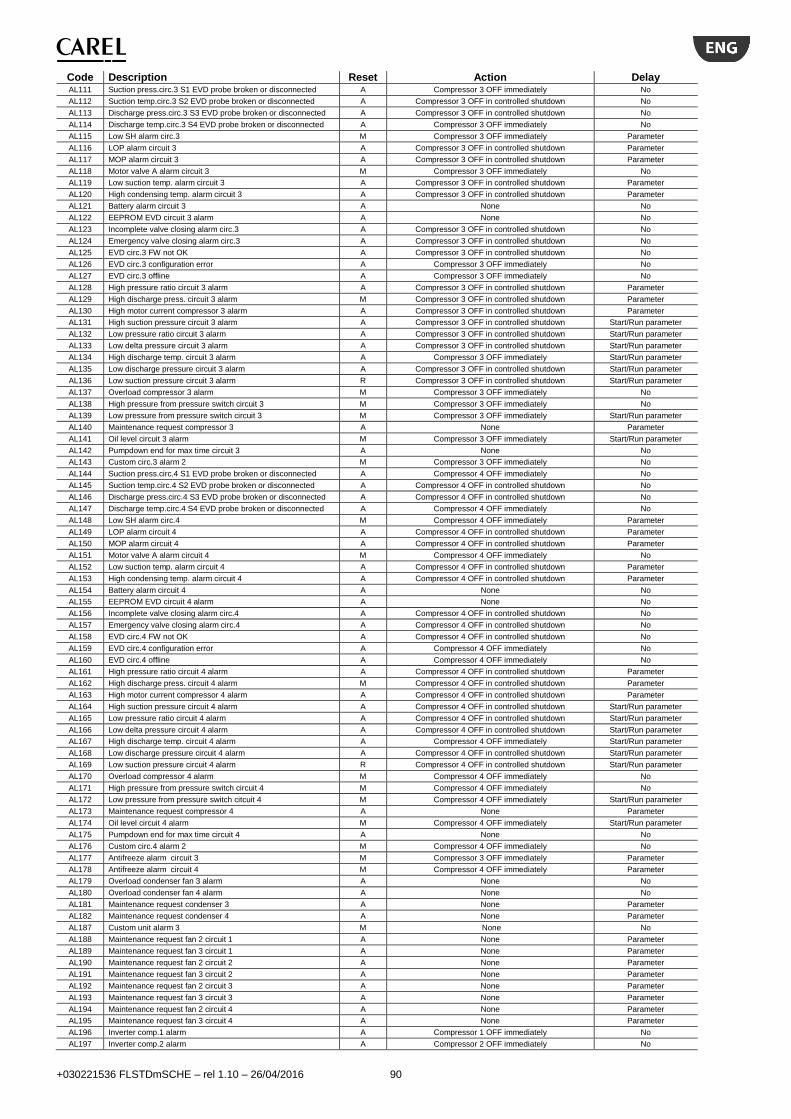
+030221536 FLSTDmSCHE – rel 1.10 – 26/04/2016 90
Code Description Reset Action Delay AL111 Suction press.circ.3 S1 EVD probe broken or disconnected A Compressor 3 OFF immediately No
AL112 Suction temp.circ.3 S2 EVD probe broken or disconnected A Compressor 3 OFF in controlled shutdown No
AL113 Discharge press.circ.3 S3 EVD probe broken or disconnected A Compressor 3 OFF in controlled shutdown No
AL114 Discharge temp.circ.3 S4 EVD probe broken or disconnected A Compressor 3 OFF immediately No
AL115 Low SH alarm circ.3 M Compressor 3 OFF immediately Parameter
AL116 LOP alarm circuit 3 A Compressor 3 OFF in controlled shutdown Parameter
AL117 MOP alarm circuit 3 A Compressor 3 OFF in controlled shutdown Parameter
AL118 Motor valve A alarm circuit 3 M Compressor 3 OFF immediately No
AL119 Low suction temp. alarm circuit 3 A Compressor 3 OFF in controlled shutdown Parameter
AL120 High condensing temp. alarm circuit 3 A Compressor 3 OFF in controlled shutdown Parameter
AL121 Battery alarm circuit 3 A None No
AL122 EEPROM EVD circuit 3 alarm A None No
AL123 Incomplete valve closing alarm circ.3 A Compressor 3 OFF in controlled shutdown No
AL124 Emergency valve closing alarm circ.3 A Compressor 3 OFF in controlled shutdown No
AL125 EVD circ.3 FW not OK A Compressor 3 OFF in controlled shutdown No
AL126 EVD circ.3 configuration error A Compressor 3 OFF immediately No
AL127 EVD circ.3 offline A Compressor 3 OFF immediately No
AL128 High pressure ratio circuit 3 alarm A Compressor 3 OFF in controlled shutdown Parameter
AL129 High discharge press. circuit 3 alarm M Compressor 3 OFF in controlled shutdown Parameter
AL130 High motor current compressor 3 alarm A Compressor 3 OFF in controlled shutdown Parameter
AL131 High suction pressure circuit 3 alarm A Compressor 3 OFF in controlled shutdown Start/Run parameter
AL132 Low pressure ratio circuit 3 alarm A Compressor 3 OFF in controlled shutdown Start/Run parameter
AL133 Low delta pressure circuit 3 alarm A Compressor 3 OFF in controlled shutdown Start/Run parameter
AL134 High discharge temp. circuit 3 alarm A Compressor 3 OFF immediately Start/Run parameter
AL135 Low discharge pressure circuit 3 alarm A Compressor 3 OFF in controlled shutdown Start/Run parameter
AL136 Low suction pressure circuit 3 alarm R Compressor 3 OFF in controlled shutdown Start/Run parameter
AL137 Overload compressor 3 alarm M Compressor 3 OFF immediately No
AL138 High pressure from pressure switch circuit 3 M Compressor 3 OFF immediately No
AL139 Low pressure from pressure switch circuit 3 M Compressor 3 OFF immediately Start/Run parameter
AL140 Maintenance request compressor 3 A None Parameter
AL141 Oil level circuit 3 alarm M Compressor 3 OFF immediately Start/Run parameter
AL142 Pumpdown end for max time circuit 3 A None No
AL143 Custom circ.3 alarm 2 M Compressor 3 OFF immediately No
AL144 Suction press.circ.4 S1 EVD probe broken or disconnected A Compressor 4 OFF immediately No
AL145 Suction temp.circ.4 S2 EVD probe broken or disconnected A Compressor 4 OFF in controlled shutdown No
AL146 Discharge press.circ.4 S3 EVD probe broken or disconnected A Compressor 4 OFF in controlled shutdown No
AL147 Discharge temp.circ.4 S4 EVD probe broken or disconnected A Compressor 4 OFF immediately No
AL148 Low SH alarm circ.4 M Compressor 4 OFF immediately Parameter
AL149 LOP alarm circuit 4 A Compressor 4 OFF in controlled shutdown Parameter
AL150 MOP alarm circuit 4 A Compressor 4 OFF in controlled shutdown Parameter
AL151 Motor valve A alarm circuit 4 M Compressor 4 OFF immediately No
AL152 Low suction temp. alarm circuit 4 A Compressor 4 OFF in controlled shutdown Parameter
AL153 High condensing temp. alarm circuit 4 A Compressor 4 OFF in controlled shutdown Parameter
AL154 Battery alarm circuit 4 A None No
AL155 EEPROM EVD circuit 4 alarm A None No
AL156 Incomplete valve closing alarm circ.4 A Compressor 4 OFF in controlled shutdown No
AL157 Emergency valve closing alarm circ.4 A Compressor 4 OFF in controlled shutdown No
AL158 EVD circ.4 FW not OK A Compressor 4 OFF in controlled shutdown No
AL159 EVD circ.4 configuration error A Compressor 4 OFF immediately No
AL160 EVD circ.4 offline A Compressor 4 OFF immediately No
AL161 High pressure ratio circuit 4 alarm A Compressor 4 OFF in controlled shutdown Parameter
AL162 High discharge press. circuit 4 alarm M Compressor 4 OFF in controlled shutdown Parameter
AL163 High motor current compressor 4 alarm A Compressor 4 OFF in controlled shutdown Parameter
AL164 High suction pressure circuit 4 alarm A Compressor 4 OFF in controlled shutdown Start/Run parameter
AL165 Low pressure ratio circuit 4 alarm A Compressor 4 OFF in controlled shutdown Start/Run parameter
AL166 Low delta pressure circuit 4 alarm A Compressor 4 OFF in controlled shutdown Start/Run parameter
AL167 High discharge temp. circuit 4 alarm A Compressor 4 OFF immediately Start/Run parameter
AL168 Low discharge pressure circuit 4 alarm A Compressor 4 OFF in controlled shutdown Start/Run parameter
AL169 Low suction pressure circuit 4 alarm R Compressor 4 OFF in controlled shutdown Start/Run parameter
AL170 Overload compressor 4 alarm M Compressor 4 OFF immediately No
AL171 High pressure from pressure switch circuit 4 M Compressor 4 OFF immediately No
AL172 Low pressure from pressure switch citcuit 4 M Compressor 4 OFF immediately Start/Run parameter
AL173 Maintenance request compressor 4 A None Parameter
AL174 Oil level circuit 4 alarm M Compressor 4 OFF immediately Start/Run parameter
AL175 Pumpdown end for max time circuit 4 A None No
AL176 Custom circ.4 alarm 2 M Compressor 4 OFF immediately No
AL177 Antifreeze alarm circuit 3 M Compressor 3 OFF immediately Parameter
AL178 Antifreeze alarm circuit 4 M Compressor 4 OFF immediately Parameter
AL179 Overload condenser fan 3 alarm A None No
AL180 Overload condenser fan 4 alarm A None No
AL181 Maintenance request condenser 3 A None Parameter
AL182 Maintenance request condenser 4 A None Parameter
AL187 Custom unit alarm 3 M None No
AL188 Maintenance request fan 2 circuit 1 A None Parameter
AL189 Maintenance request fan 3 circuit 1 A None Parameter
AL190 Maintenance request fan 2 circuit 2 A None Parameter
AL191 Maintenance request fan 3 circuit 2 A None Parameter
AL192 Maintenance request fan 2 circuit 3 A None Parameter
AL193 Maintenance request fan 3 circuit 3 A None Parameter
AL194 Maintenance request fan 2 circuit 4 A None Parameter
AL195 Maintenance request fan 3 circuit 4 A None Parameter
AL196 Inverter comp.1 alarm A Compressor 1 OFF immediately No
AL197 Inverter comp.2 alarm A Compressor 2 OFF immediately No
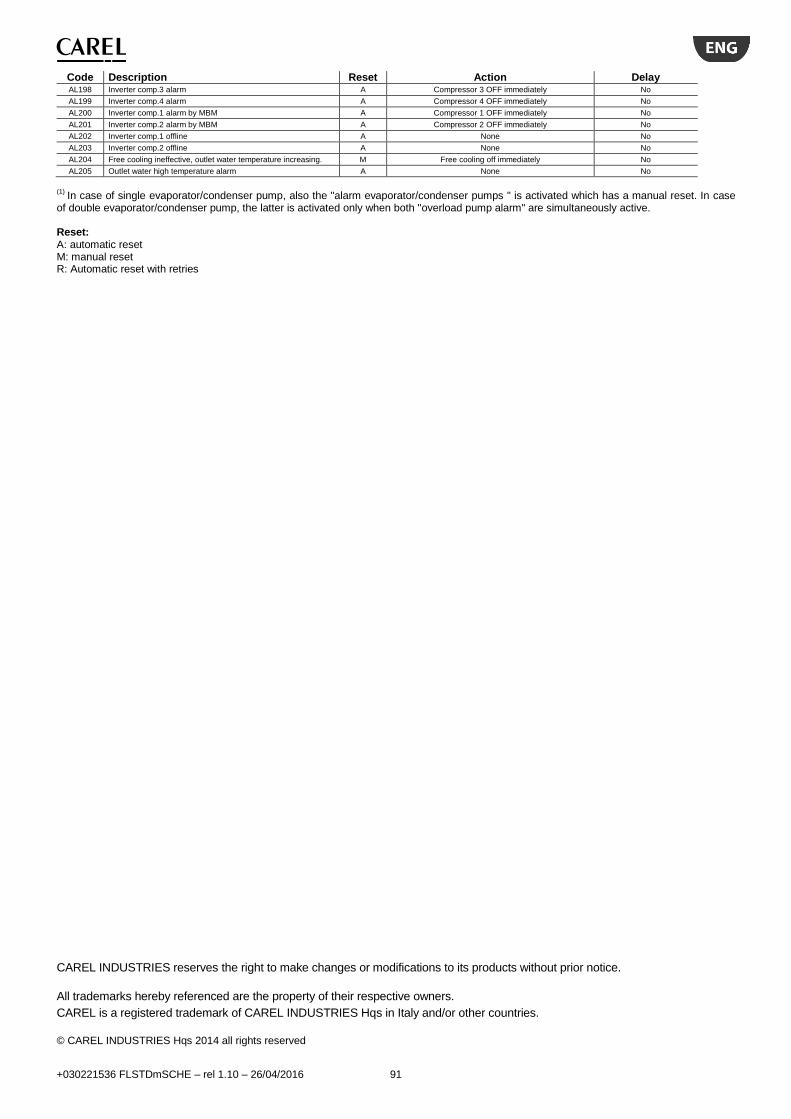
+030221536 FLSTDmSCHE – rel 1.10 – 26/04/2016 91
Code Description Reset Action Delay AL198 Inverter comp.3 alarm A Compressor 3 OFF immediately No
AL199 Inverter comp.4 alarm A Compressor 4 OFF immediately No
AL200 Inverter comp.1 alarm by MBM A Compressor 1 OFF immediately No
AL201 Inverter comp.2 alarm by MBM A Compressor 2 OFF immediately No
AL202 Inverter comp.1 offline A None No
AL203 Inverter comp.2 offline A None No
AL204 Free cooling ineffective, outlet water temperature increasing. M Free cooling off immediately No
AL205 Outlet water high temperature alarm A None No
(1)
In case of single evaporator/condenser pump, also the "alarm evaporator/condenser pumps " is activated which has a manual reset. In case of double evaporator/condenser pump, the latter is activated only when both "overload pump alarm" are simultaneously active. Reset: A: automatic reset M: manual reset R: Automatic reset with retries
CAREL INDUSTRIES reserves the right to make changes or modifications to its products without prior notice.
All trademarks hereby referenced are the property of their respective owners.
CAREL is a registered trademark of CAREL INDUSTRIES Hqs in Italy and/or other countries.
© CAREL INDUSTRIES Hqs 2014 all rights reserved

+030221536 FLSTDmSCHE – rel 1.10 – 26/04/2016 92
CAREL INDUSTRIES S.p.a.
Via dell’Industria, 11 - 35020 Brugine - Padova (Italy) Tel. (+39) 049.9716611 Fax (+39) 049.9716600 http://www.carel.com - e-mail: [email protected]
FL
ST
Dm
SC
HE
– r
el 1.1
0 –
26/0
4/2
016


![Product Offering [Read-Only]](https://static.fdocuments.us/doc/165x107/61fc9e699d50e757a521b927/product-offering-read-only.jpg)

