Flow Sensor FUS20 - Microsoft‘ .Flow sensor ②.Output type Code N P Output type 2 points NPN...
36
No, IXPN E01-01E Flow Sensor Suction lift verification of small workpiece, which is hard to detect bypressure sensor, or flow management is possible. FUS20
Transcript of Flow Sensor FUS20 - Microsoft‘ .Flow sensor ②.Output type Code N P Output type 2 points NPN...
No, IXPN E01-01E
Flow SensorSuction lift verification of small workpiece,
which is hard to detect bypressure sensor,or flow management is possible.
FUS20
2011 NEW PRODUCTS
Please be sure to read before handling the product. Please refer to "safety instructions", "common safety instructions for products listed in this manual", "common safety instructions for flow controller" from page 24 through 35.
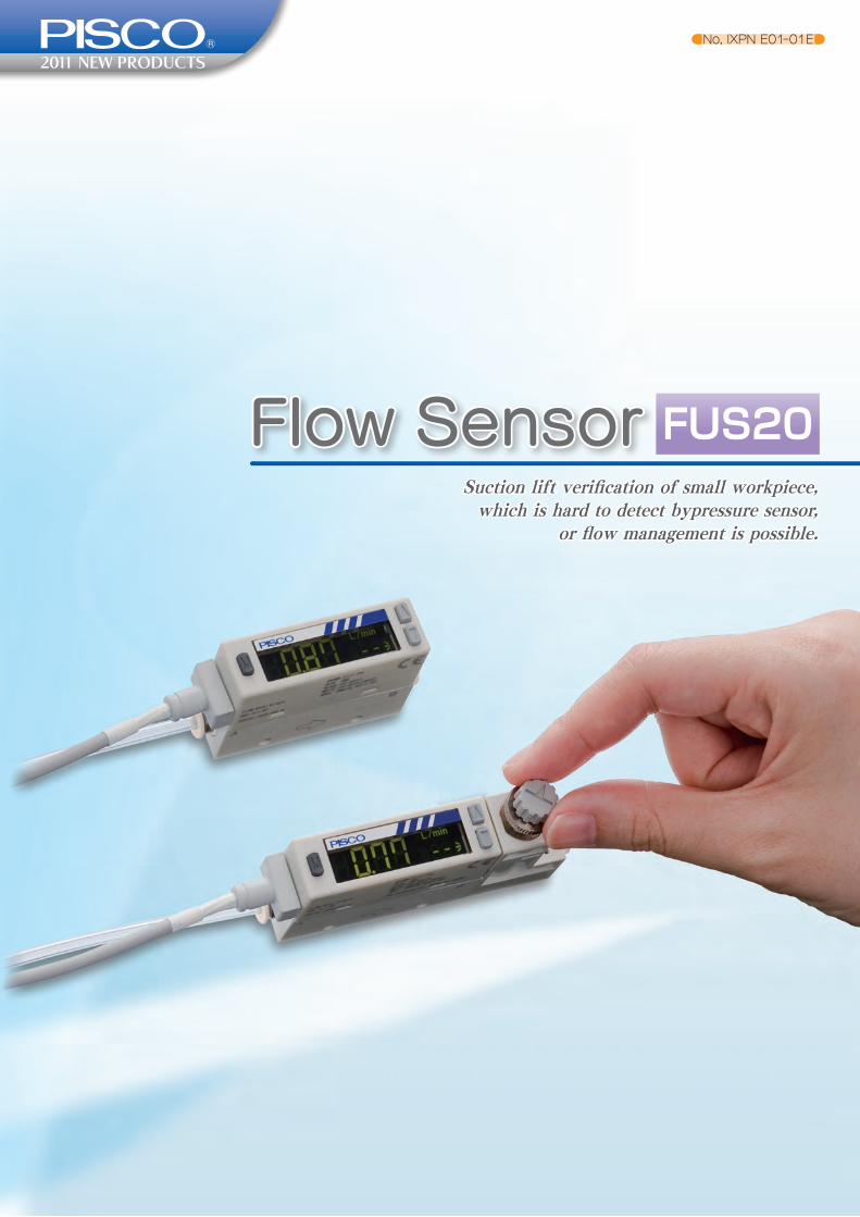
■Dual display ■2-color indication
Main display (real-time flow rate) Sub display (flow direction, etc.) Green/red switchable
Flow rate unit
2
Characteristics
Built-in needle valve modelFlow adjustable needle valve and sensor are integrated into one unit. Fuss-free plumbing and minimized installation space are realized.
Panel mount is possible.Bracket for panel mount is available.Sensor as well as built-in needle valve sensor can be panel mounted.Since coherent installation is possible, one large panel cut make possible for mounting multiple sensors with minimum space and process.
Dual display / 2 color indication featureIntroduction of main and sub display improve operability.Additionally, 2 colors indication makes easy cognition of error.
High accuracy, Max.±3%F.S.Accuracy of ±3%F.S is realized, and precise flow measurement is possible.
Coherent installation is possible
Flow Sensor
Please be sure to read before handling the product. Please refer to "safety instructions", "common safety instructions for products listed in this manual", "common safety instructions for flow controller" from page 24 through 35.
>>>http://www.pisco.co.jp
3
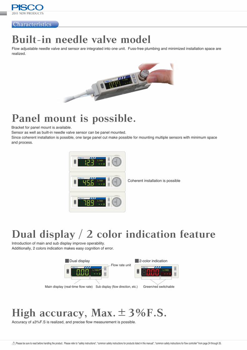
Bidirectional flow measurement is possible.Bidirectional flow model can measure the flow of preset direction. Flexibility of the plumbing installation improves and usable for reverse flow detection.
Free installing orientationThe sensor can be mounted in any orientation: top, bottom, left, or right.
Quick response time, Max. 50msec.High-speed response is realized by incorporating a platinum sensor chip processed with silicon micromachining. It contributes to shorten takt time.
No straight piping requiresThe newly proposed rectifying structure eliminates the need for a straight piping section upstream or downstream.
Forward direction Bidirectional Reverse direction
Elbow plumbing is possible.
2011 NEW PRODUCTS
Please be sure to read before handling the product. Please refer to "safety instructions", "common safety instructions for products listed in this manual", "common safety instructions for flow controller" from page 24 through 35.4
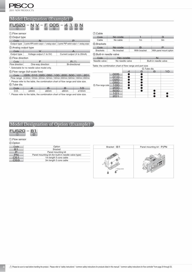
Model Designation (Example)
①.Flow sensor②.Output type
Code N POutput type 2 points NPN switch output + 1 analog output 2 points PNP switch output + 1 analog output
③.Analog output typeCode V A
Output type Voltage output (1 to 5V) Current output (4 to 20mA)④.Flow direction
Code F R (*)Flow direction One-way direction Bi-directional*. Selectable for no needle valve model only.⑤.Flow range (full-scale flow)
Code 005 010 020 050 100 200 500 101 201Flow range 0.5l/min 1l/min 2l/min 5l/min 10l/min 20l/min 50l/min 100l/min 200l/min
*. Please refer to the table, the combination chart of flow range and tube size.⑥.Tube dia.
Code 4 6 8 10O.D. ø4mm ø6mm ø8mm ø10mm
*. Please refer to the table, the combination chart of flow range and tube size.
FUS20①
N②
V③
– F④
005⑤
⑦.CableCode No code 1 3Cable No cable 1m 3m
⑧.BracketsCode No code B P
Brackets No bracket With bracket With panel mount option⑨.Built-in needle valve
Code No code NNeedle valve No needle valve Built-in needle valve
– – 4⑥
1⑦
B⑧
N⑨
Table: the combination chart of flow range and port size
①.Flow sensor②.Option
Code OptionB1 BracketP Panel mounting kit
PN Panel mounting kit (for built-in needle valve type)C51 1m length 5 core cableC53 3m length 5 core cable
FUS20①
B1②
–
⑥.Tube dia.4 6 8 10
⑤.Flow range code
005 ● ●010 ● ●020 ● ●050 ● ●100 ● ●200 ● ●500 ● ●101 ● ●201 ● ●
Model Designation of Option (Example)
Bracket:B1 Panel mounting kit:P,PN
Fixing screw
Flow Sensor
Please be sure to read before handling the product. Please refer to "safety instructions", "common safety instructions for products listed in this manual", "common safety instructions for flow controller" from page 24 through 35.
>>>http://www.pisco.co.jp
5
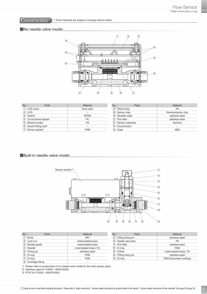
Construction
No, Parts Material⑧ Resin body PA⑨ Sensor chip Semiconductor chip⑩ Rectifier plate stainless steel⑪ Port filter stainless steel⑫ Sensor substrate Alumina⑬ Circuit board −⑭ Case ABS
① ② ③
■No needle valve model
④
⑤
⑥
⑦⑧⑨⑩⑪
⑫
⑬
⑭
*. Parts materials are subject to change without notice.
■Built-in needle valve model
No, Parts Material① LCD cover Acryl resin② LCD −③ Switch EPDM④ Circuit board spacer PC⑤ Module holder PA⑥ Quick-Fitting Joint −⑦ Sensor gasket FKM
①
②
③
④
⑤
⑥
⑦
⑧
⑨⑩⑪⑫⑬⑭⑮
Sensor section*1
No, Parts Material⑨ Fitting fixing pin stainless steel⑩ Needle valve body PA⑪ Port filter stainless steel⑫ O-ring FKM⑬ Orifice nickel-plated brass (*3)⑭ Fitting fixing pin stainless steel⑮ O-ring FKM (fluororesin coating)
No, Parts Material① Knob PBT② Lock nut nickel-plated brass③ Needle guide nickel-plated brass④ Needle nickel-plated brass (*2)⑤ Fixing pin stainless steel⑥ O-ring FKM⑦ O-ring FKM⑧ Cartridge fitting −
*1. Please refer to construction of no needle valve model for the main sensor parts.*2. Stainless steel for FUS20…005/010/020*3. PTFE for FUS20…005/010/020
2011 NEW PRODUCTS
Please be sure to read before handling the product. Please refer to "safety instructions", "common safety instructions for products listed in this manual", "common safety instructions for flow controller" from page 24 through 35.6
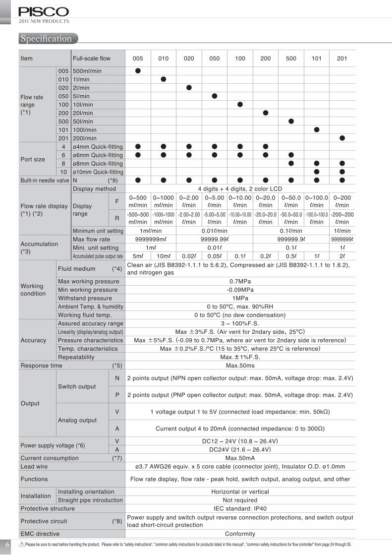
Specification
Item Full-scale flow 005 010 020 050 100 200 500 101 201
Flow rate range(*1)
005 500ml/min ●010 1l/min ●020 2l/min ●050 5l/min ●100 10l/min ●200 20l/min ●500 50l/min ●101 100l/min ●201 200l/min ●
Port size
4 ø4mm Quick-fitting ● ● ● ● ● ●6 ø6mm Quick-fitting ● ● ● ● ● ● ●8 ø8mm Quick-fitting ● ● ●
10 ø10mm Quick-fitting ● ●Built-in needle valve N (*9) ● ● ● ● ● ● ● ● ●
Flow rate display(*1) (*2)
Display method 4 digits + 4 digits, 2 color LCD
Display range
F 0~500ml/min
0~1000ml/min
0~2.00l/min
0~5.00l/min
0~10.00l/min
0~20.0l/min
0~50.0l/min
0~100.0l/min
0~200l/min
R -500~500ml/min
-1000~1000ml/min
-2.00~2.00l/min
-5.00~5.00l/min
-10.00~10.00l/min
-20.0~20.0l/min
-50.0~50.0l/min
-100.0~100.0l/min
-200~200l/min
Minimum unit setting 1ml/min 0.01l/min 0.1l/min 1l/min
Accumulation(*3)
Max flow rate 9999999ml 99999.99l 999999.9l 9999999lMini. unit setting 1ml 0.01l 0.1l 1lAccumulated pulse output rate 5ml 10ml 0.02l 0.05l 0.1l 0.2l 0.5l 1l 2l
Working condition
Fluid medium (*4) Clean air (JIS B8392-1.1.1 to 5.6.2), Compressed air (JIS B8392-1.1.1 to 1.6.2), and nitrogen gas
Max working pressure 0.7MPaMin working pressure -0.09MPaWithstand pressure 1MPaAmbient Temp. & humidity 0 to 50ºC, max. 90%RHWorking fluid temp. 0 to 50ºC (no dew condensation)
Accuracy
Assured accuracy range 3 ~ 100%F.S.Linearity (display/analog output) Max ±3%F.S. (Air vent for 2ndary side、25ºC)Pressure characteristics Max ±5%F.S. (-0.09 to 0.7MPa, where air vent for 2ndary side is reference)Temp. characteristics Max ±0.2%F.S./ºC (15 to 35ºC, where 25ºC is reference)Repeatability Max.±1%F.S.
Response time (*5) Max.50ms
Output
Switch outputN 2 points output (NPN open collector output: max. 50mA, voltage drop: max. 2.4V)
P 2 points output (PNP open collector output: max. 50mA, voltage drop: max. 2.4V)
Analog outputV 1 voltage output 1 to 5V (connected load impedance: min. 50kΩ)
A Current output 4 to 20mA (connected impedance: 0 to 300Ω)
Power supply voltage (*6) V DC12 ~ 24V (10.8 ~ 26.4V)A DC24V (21.6 ~ 26.4V)
Current consumption (*7) Max.50mALead wire ø3.7 AWG26 equiv. x 5 core cable (connector joint), Insulator O.D. ø1.0mm
Functions Flow rate display, flow rate - peak hold, switch output, analog output, and other
Installation Installing orientation Horizontal or verticalStraight pipe introduction Not required
Protective structure IEC standard: IP40
Protective circuit (*8) Power supply and switch output reverse connection protections, and switch output load short-circuit protection
EMC directive Conformity
Flow Sensor
Please be sure to read before handling the product. Please refer to "safety instructions", "common safety instructions for products listed in this manual", "common safety instructions for flow controller" from page 24 through 35.
>>>http://www.pisco.co.jp
7
ø4mm Quick-fitting model About 50g (about 80g for built-in needle valve model)ø6mm Quick-fitting model About 50g (about 80g for built-in needle valve model)ø8mm Quick-fitting model About 70g (about 110g for built-in needle valve model)ø10mm Quick-fitting model About 75g (about 115g for built-in needle valve model)
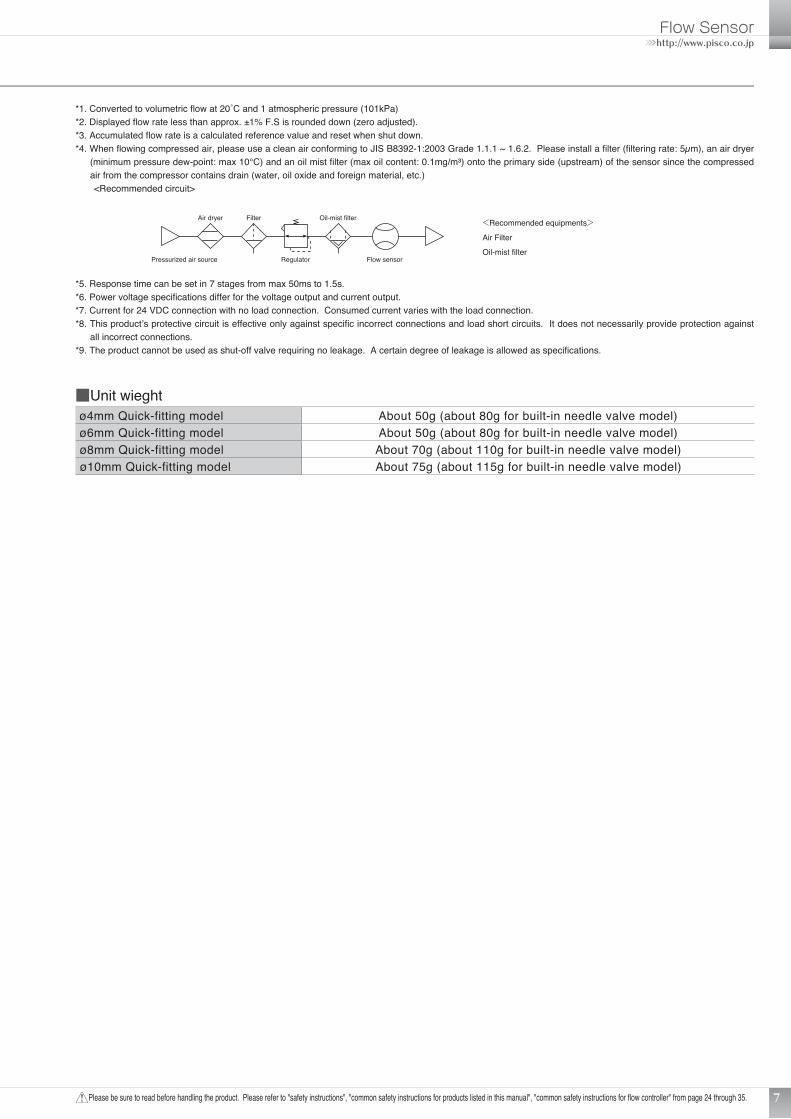
*1. Converted to volumetric flow at 20˚C and 1 atmospheric pressure (101kPa)*2. Displayed flow rate less than approx. ±1% F.S is rounded down (zero adjusted).*3. Accumulated flow rate is a calculated reference value and reset when shut down.*4. When flowing compressed air, please use a clean air conforming to JIS B8392-1:2003 Grade 1.1.1 ~ 1.6.2. Please install a filter (filtering rate: 5µm), an air dryer
(minimum pressure dew-point: max 10°C) and an oil mist filter (max oil content: 0.1mg/m³) onto the primary side (upstream) of the sensor since the compressed air from the compressor contains drain (water, oil oxide and foreign material, etc.)
<Recommended circuit>
■Unit wieght
空気圧源 流量センサ
フィルタ
エアドライヤ レギュレータ
オイルミストフィルタ <推奨機器>エアフィルタオイルミストフィルタ
Pressurized air source Flow sensor
FilterAir dryer
Regulator
Oil-mist filter <Recommended equipments>
Air Filter
Oil-mist filter
*5. Response time can be set in 7 stages from max 50ms to 1.5s.*6. Power voltage specifications differ for the voltage output and current output.*7. Current for 24 VDC connection with no load connection. Consumed current varies with the load connection.*8. This product’s protective circuit is effective only against specific incorrect connections and load short circuits. It does not necessarily provide protection against
all incorrect connections.*9. The product cannot be used as shut-off valve requiring no leakage. A certain degree of leakage is allowed as specifications.
2011 NEW PRODUCTS
Please be sure to read before handling the product. Please refer to "safety instructions", "common safety instructions for products listed in this manual", "common safety instructions for flow controller" from page 24 through 35.
55 L12-∅3.4
15
L127
H2
H3 H
11.
53.
6 17
9.5
2-M3×0.5 Depth 515.5
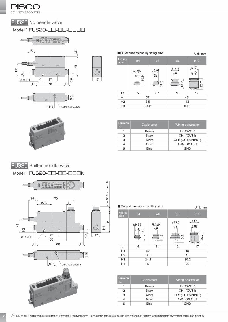
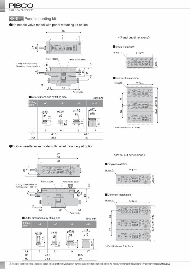
■Outer dimensions by fitting size
ø4
L1
Fittingsize
5 6.1 9 17H1 37 43H2 8.5 13H3 24.2 30.2
ø6 ø8 ø10
ø9.95ø4
10.9
ø9.95ø6
11.7
ø15.6ø8
18.2
ø17ø10
20.7
Unit: mm
H1
H4
17
9.5
2-M3×0.5 Depth 515.5
8055
70
min
.10.
5~m
ax.1
9
827.5
L1
2-∅3.4
15
L1
27
H2
H3
3.6
■Outer dimensions by fitting size
ø4
L1
Fittingsize
5 6.1 9 17H1 37 43H2 8.5 13H3 24.2 30.2H4 17 23
ø6 ø8 ø10
ø9.95ø4
10.9
ø9.95ø6
11.7
ø15.6ø8
18.2
ø17ø10
20.7
Unit: mm
8
FUS20 No needle valve
FUS20 Built-in needle valve
Model:FUS20-□□-□□-□□□□
Model:FUS20-□□-□□-□□□N
Terminal no. Cable color Wiring destination
1 Brown DC12-24V2 Black CH1 (OUT1)3 White CH2 (OUT2/INPUT)4 Gray ANALOG OUT5 Blue GND
Terminal no. Cable color Wiring destination
1 Brown DC12-24V2 Black CH1 (OUT1)3 White CH2 (OUT2/INPUT)4 Gray ANALOG OUT5 Blue GND
Flow Sensor
Please be sure to read before handling the product. Please refer to "safety instructions", "common safety instructions for products listed in this manual", "common safety instructions for flow controller" from page 24 through 35.
>>>http://www.pisco.co.jp
5
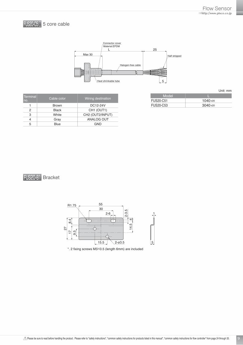
25LMax 30
Halogen-free cable
Half stripped
Heat shrinkable tube
Connector coverMaterial:EPDM
2-ø3.5
1727
5
1
R1.75
8.4
2-3.
514
.54
9.5
15.5
2-63055
*. 2 fixing screws M3×0.5 (length 6mm) are included
9
FUS20-C5 □ 5 core cable
FUS20-B1 Bracket
Unit: mmModel L
FUS20-C51 1040±20
FUS20-C53 3040±20
Terminal no. Cable color Wiring destination
1 Brown DC12-24V2 Black CH1 (OUT1)3 White CH2 (OUT2/INPUT)4 Gray ANALOG OUT5 Blue GND
2011 NEW PRODUCTS
Please be sure to read before handling the product. Please refer to "safety instructions", "common safety instructions for products listed in this manual", "common safety instructions for flow controller" from page 24 through 35.
*. Panel thickness: 0.8 ~ 6mm
<Panel cut dimensions>
■Single installation
■Coherent installation
2828
4x max R1
22.5
+28×
(n-1
)
57.5±0.5
22.5±
0.5
57.5±0.54x max R1
L155L1
2 fixing screws(M3×0.5)Tightening torque : 0.06N・m
20
0.1
Panel stopper Panel holder cover
Panel holder
15
4
1.4
H2
H1
28 1861
7871
■Outer dimensions by fitting size
ø4
L1
Fittingsize
5 6.1 9 17H1 40.5 46.5H2 28.5 30
ø6 ø8 ø10
ø9.95ø4
10.9
ø9.95ø6
11.7
ø15.6ø8
18.2
ø17ø10
20.7
Unit: mm
2828
2 fixing screws(M3×0.5)Tightening torque : 0.06N・m
20
Panel holder coverPanel stopper
Panel holder
4
15
H1H
21.
4
80
1828
8878
95
4x max R1
4x max R1
22.5
+28×
(n-1
)
74.5±0.5
22.5±
0.5
74.5±0.5
L1L1
<Panel cut dimensions>
■Single installation
■Coherent installation
*. Panel thickness: 0.8 ~ 6mm
■Outer dimensions by fitting size
ø4
L1
Fittingsize
5 6.1 9 17H1 40.5 46.5H2 28.5 30
ø6 ø8 ø10
ø9.95ø4
10.9
ø9.95ø6
11.7
ø15.6ø8
18.2
ø17ø10
20.7
Unit: mm
10
FUS20-P □ Panel mounting kit●No needle valve model with panel mounting kit option
●Built-in needle valve model with panel mounting kit option
Flow Sensor
Please be sure to read before handling the product. Please refer to "safety instructions", "common safety instructions for products listed in this manual", "common safety instructions for flow controller" from page 24 through 35.
>>>http://www.pisco.co.jp
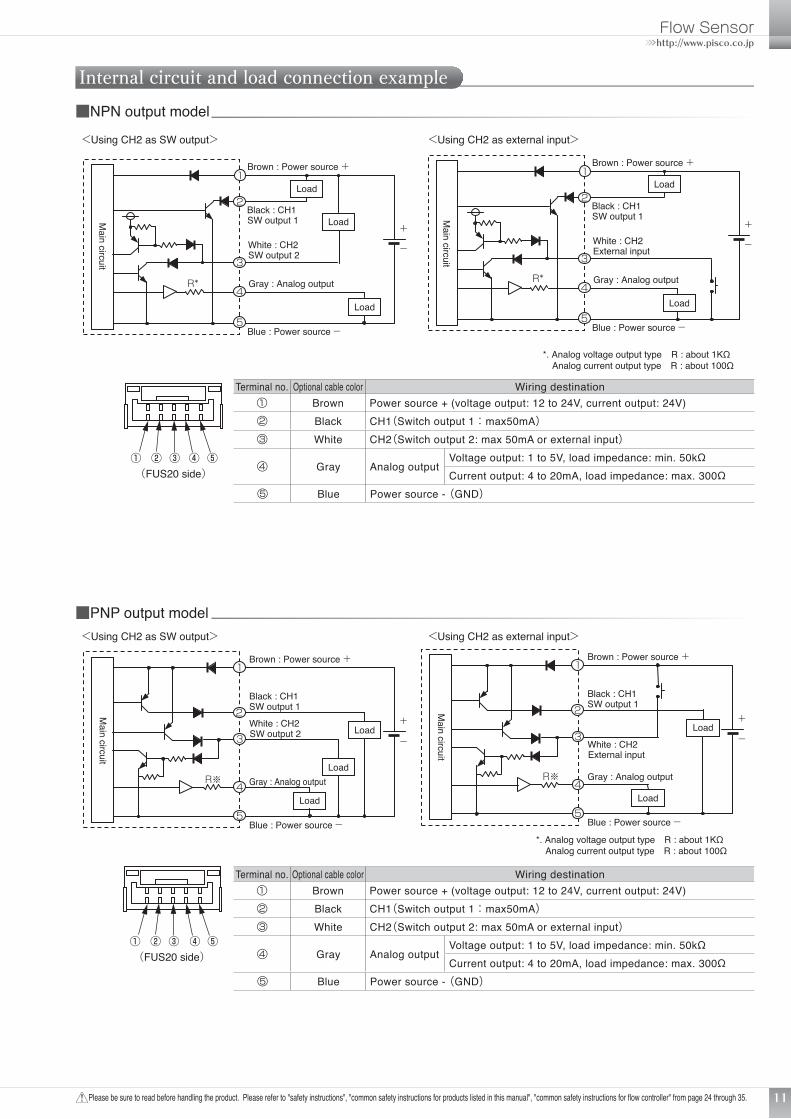
Load
Load
Load
Brown : Power source +
Gray : Analog output
Black : CH1 SW output 1
White : CH2
R*
SW output 2
Blue : Power source -
Brown : Power source +
Gray : Analog output
Black : CH1 SW output 1
White : CH2 External input
Blue : Power source -
+
-
1
2
3
4
5
Load
Load
+
-
1
2
3
4
5
<Using CH2 as SW output>
(FUS20 side)
<Using CH2 as external input>
R*
*. Analog voltage output type R : about 1KΩ Analog current output type R : about 100Ω
Main circuit
Main circuit
Load
Load
Load
Brown : Power source +
Gray : Analog output
Blue : Power source -
+
-
Black : CH1 SW output 1
White : CH2 SW output 2
1
2
3
4
5
Load
Load
Brown : Power source +
Gray : Analog output
Blue : Power source -
+
-
Black : CH1 SW output 1
White : CH2 External input
1
2
3
4
5
<Using CH2 as SW output> <Using CH2 as external input>
(FUS20 side)
R※ R※
*. Analog voltage output type R : about 1KΩ Analog current output type R : about 100Ω
Main circuit
Main circuit
11
Internal circuit and load connection example■NPN output model
■PNP output model
Terminal no. Optional cable color Wiring destination① Brown Power source + (voltage output: 12 to 24V, current output: 24V)② Black CH1(Switch output 1:max50mA)③ White CH2(Switch output 2: max 50mA or external input)
④ Gray Analog outputVoltage output: 1 to 5V, load impedance: min. 50kΩCurrent output: 4 to 20mA, load impedance: max. 300Ω
⑤ Blue Power source - (GND)
2011 NEW PRODUCTS
Please be sure to read before handling the product. Please refer to "safety instructions", "common safety instructions for products listed in this manual", "common safety instructions for flow controller" from page 24 through 35.12
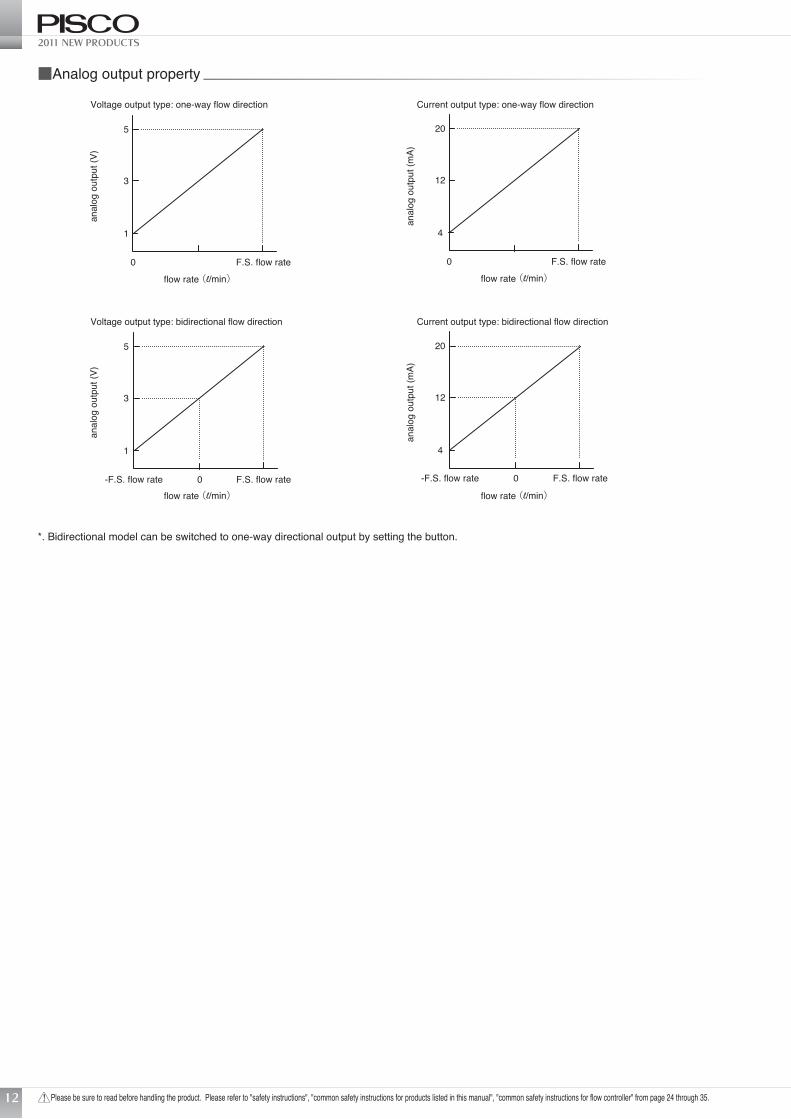
■Analog output property
Voltage output type: one-way flow direction Current output type: one-way flow direction
Voltage output type: bidirectional flow direction Current output type: bidirectional flow direction
flow rate (l/min)
0 F.S. flow rate
5
1
3
flow rate (l/min)
0 F.S. flow rate
20
4
12
-F.S. flow rate F.S. flow rate0
5
1
3
flow rate (l/min) flow rate (l/min)
20
4
12
-F.S. flow rate F.S. flow rate0
anal
og o
utpu
t (V)
anal
og o
utpu
t (m
A)
anal
og o
utpu
t (V)
anal
og o
utpu
t (m
A)
*. Bidirectional model can be switched to one-way directional output by setting the button.
Flow Sensor
Please be sure to read before handling the product. Please refer to "safety instructions", "common safety instructions for products listed in this manual", "common safety instructions for flow controller" from page 24 through 35.
>>>http://www.pisco.co.jp
00.010.020.030.040.050.060.070.080.090.1
0 0.50.40.30.20.1flow rate (l/min)
pres
sure
loss
(kP
a)
pres
sure
loss
(kP
a)
pres
sure
loss
(kP
a)
pres
sure
loss
(kP
a)
pres
sure
loss
(kP
a)
pres
sure
loss
(kP
a)
0.1MPa
0.3MPa
0.5MPa
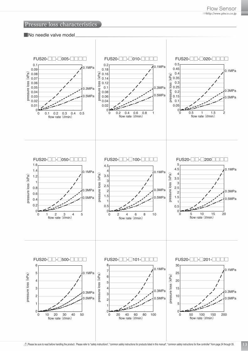
FUS20-□□-□005-□□□□ FUS20-□□-□020-□□□□
FUS20-□□-□050-□□□□ FUS20-□□-□100-□□□□ FUS20-□□-□200□□□□
FUS20-□□-□010-□□□□
0.1MPa
0.3MPa
0.5MPa
00.020.040.060.080.1
0.120.140.160.180.2
0 10.80.60.40.2flow rate (l/min)
0.1MPa
0.3MPa
0.5MPa
00.050.1
0.150.2
0.250.3
0.350.4
0.450.5
0 21.510.5flow rate (l/min)
0.1MPa
0.3MPa
0.5MPa
00.20.40.60.8
11.21.41.6
543210flow rate (l/min)
0.1MPa
0.3MPa
0.5MPa
00.5
11.5
22.5
33.5
44.5
0186420flow rate (l/min)
0.1MPa
0.3MPa
0.5MPa
00.5
11.5
22.5
33.5
44.5
5
0 2015105flow rate (l/min)
pres
sure
loss
(kP
a)
pres
sure
loss
(kP
a)
pres
sure
loss
(kP
a)
FUS20-□□-□500-□□□□ FUS20-□□-□201-□□□□FUS20-□□-□101-□□□□
0.1MPa
0.3MPa0.5MPa
0
1
2
3
4
5
6
0 5040302010flow rate (l/min)
0.1MPa
0.3MPa
0.5MPa
012345678
0 10080604020flow rate (l/min)
0.1MPa
0.3MPa
0.5MPa
0
5
10
15
20
25
30
0 20015010050flow rate (l/min)
13
Pressure loss characteristics■No needle valve model
2011 NEW PRODUCTS
Please be sure to read before handling the product. Please refer to "safety instructions", "common safety instructions for products listed in this manual", "common safety instructions for flow controller" from page 24 through 35.
flow
rate
(l/m
in(A
NR
))
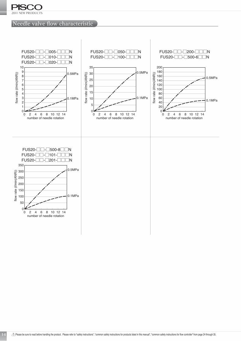
FUS20-□□-□005-□□□NFUS20-□□-□010-□□□NFUS20-□□-□020-□□□N
number of needle rotation
0123456789
10
0 14121082 4 6
0.5MPa
0.1MPa
flow
rate
(l/m
in(A
NR
))
FUS20-□□-□050-□□□NFUS20-□□-□100-□□□N
number of needle rotation
flow
rate
(l/m
in(A
NR
))
FUS20-□□-□200-□□□NFUS20-□□-□500-6□□N
number of needle rotation
flow
rate
(l/m
in(A
NR
))
FUS20-□□-□500-8□□NFUS20-□□-□101-□□□NFUS20-□□-□201-□□□N
number of needle rotation
0
5
10
15
20
25
30
35
0 14121082 4 6
0.5MPa
0.1MPa
020406080
100120140160180200
0 14121082 4 6
0.5MPa
0.1MPa
0
50
100
150
200
250
300
350
0 14121082 4 6
0.5MPa
0.1MPa
14
Needle valve flow characteristic
Flow Sensor
Please be sure to read before handling the product. Please refer to "safety instructions", "common safety instructions for products listed in this manual", "common safety instructions for flow controller" from page 24 through 35.
>>>http://www.pisco.co.jp
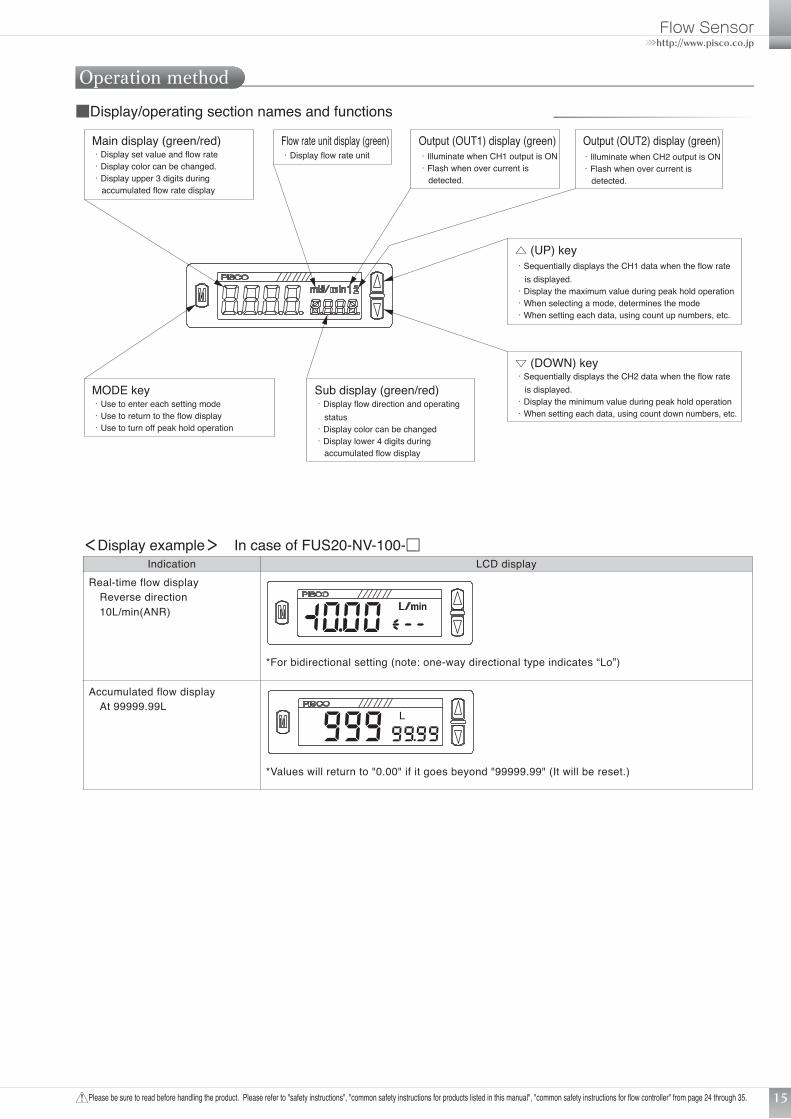
MODE key ・Use to enter each setting mode・Use to return to the flow display・Use to turn off peak hold operation
△ (UP) key・Sequentially displays the CH1 data when the flow rate is displayed.・Display the maximum value during peak hold operation・When selecting a mode, determines the mode・When setting each data, using count up numbers, etc.
▽ (DOWN) key・Sequentially displays the CH2 data when the flow rate is displayed.・Display the minimum value during peak hold operation・When setting each data, using count down numbers, etc.
Main display (green/red) ・Display set value and flow rate・Display color can be changed.・Display upper 3 digits during accumulated flow rate display
Sub display (green/red) ・Display flow direction and operating status・Display color can be changed・Display lower 4 digits during accumulated flow display
Flow rate unit display (green)・Display flow rate unit
Output (OUT1) display (green)・Illuminate when CH1 output is ON・Flash when over current is detected.
Output (OUT2) display (green) ・Illuminate when CH2 output is ON・Flash when over current is detected.
15
Operation method
<Display example> In case of FUS20-NV-100-□Indication LCD display
Real-time flow display Reverse direction 10L/min(ANR)
*For bidirectional setting (note: one-way directional type indicates “Lo”)
Accumulated flow display At 99999.99L
*Values will return to "0.00" if it goes beyond "99999.99" (It will be reset.)
■Display/operating section names and functions

2011 NEW PRODUCTS
Please be sure to read before handling the product. Please refer to "safety instructions", "common safety instructions for products listed in this manual", "common safety instructions for flow controller" from page 24 through 35.16
Some functions and settings are completed when the normal flow is displayed, and some after entering setting mode. The setting mode is divided into standard setting mode and detailed setting mode based on the frequency of use.
■Explanation of function
●Normal operationItem Description Default setting
Real-time flow display Real-time flow rate is displayed. −
Accumulated flow display
It can be changed to accumulated flow display.The switch output function includes turning the switch ON and OFF when the specified accumulated value is exceeded, and an accumulated pulse function that outputs a pulse after a set count value. It will be reset if power is turned off and can be reset with button operation or external input.
Real-time flow display
Peak hold function Maximum and minimum flow rates within a set interval are displayed. Peak hold OFFKey lock function Key operations are disabled to prevent incorrect operation. Key lock invalidError display function. The status of errors is displayed when trouble or error occurs. −
●Standard setting modeItem Description Default setting
Switch output function Having 2 points switch output, 7 operation patterns and operation stop can be set.
Both CH1 and CH2 are set to switch OFF
Forced output function Switch output is forcibly turned on to check line connections and default operation of the input device. −
Zero adjust function Zero point deviation is corrected. (Range : 0±10%F.S.) Adjusted value: 0
Flow Sensor
Please be sure to read before handling the product. Please refer to "safety instructions", "common safety instructions for products listed in this manual", "common safety instructions for flow controller" from page 24 through 35.
>>>http://www.pisco.co.jp
17
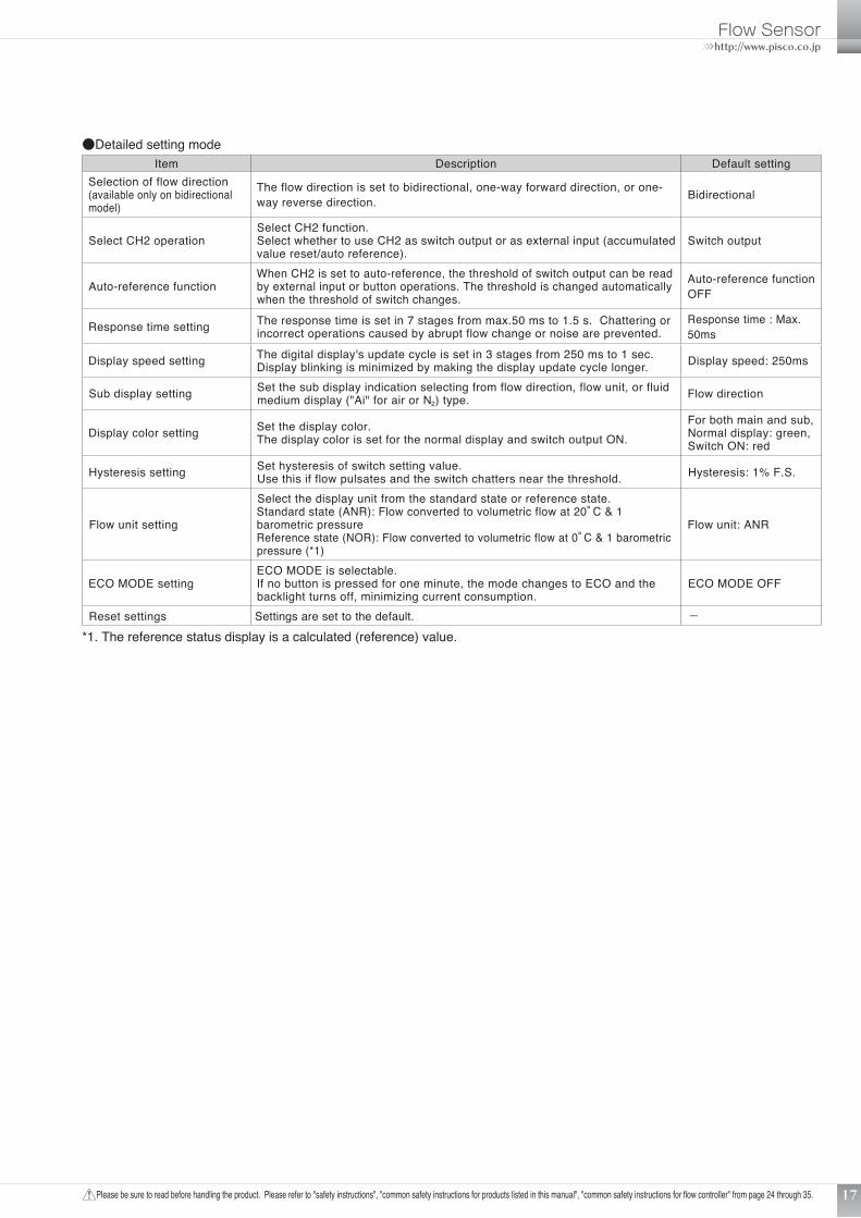
●Detailed setting modeItem Description Default setting
Selection of flow direction(available only on bidirectional model)
The flow direction is set to bidirectional, one-way forward direction, or one-way reverse direction. Bidirectional
Select CH2 operationSelect CH2 function.Select whether to use CH2 as switch output or as external input (accumulated value reset/auto reference).
Switch output
Auto-reference functionWhen CH2 is set to auto-reference, the threshold of switch output can be read by external input or button operations. The threshold is changed automatically when the threshold of switch changes.
Auto-reference function OFF
Response time setting The response time is set in 7 stages from max.50 ms to 1.5 s. Chattering or incorrect operations caused by abrupt flow change or noise are prevented.
Response time : Max. 50ms
Display speed setting The digital display's update cycle is set in 3 stages from 250 ms to 1 sec. Display blinking is minimized by making the display update cycle longer. Display speed: 250ms
Sub display setting Set the sub display indication selecting from flow direction, flow unit, or fluid medium display ("Ai" for air or N2) type. Flow direction
Display color setting Set the display color.The display color is set for the normal display and switch output ON.
For both main and sub, Normal display: green, Switch ON: red
Hysteresis setting Set hysteresis of switch setting value.Use this if flow pulsates and the switch chatters near the threshold. Hysteresis: 1% F.S.
Flow unit setting
Select the display unit from the standard state or reference state.Standard state (ANR): Flow converted to volumetric flow at 20°C & 1 barometric pressureReference state (NOR): Flow converted to volumetric flow at 0°C & 1 barometric pressure (*1)
Flow unit: ANR
ECO MODE settingECO MODE is selectable.If no button is pressed for one minute, the mode changes to ECO and the backlight turns off, minimizing current consumption.
ECO MODE OFF
Reset settings Settings are set to the default. −*1. The reference status display is a calculated (reference) value.
2011 NEW PRODUCTS
Please be sure to read before handling the product. Please refer to "safety instructions", "common safety instructions for products listed in this manual", "common safety instructions for flow controller" from page 24 through 35.18
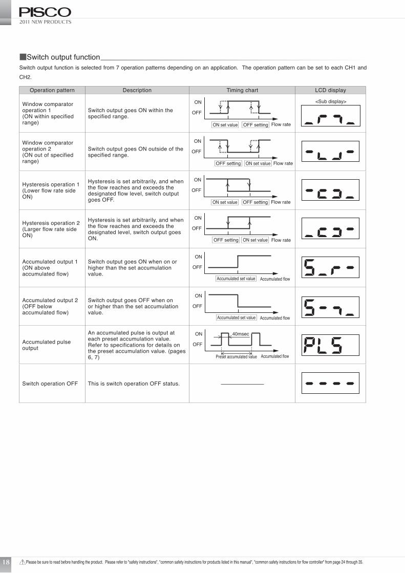
■Switch output functionSwitch output function is selected from 7 operation patterns depending on an application. The operation pattern can be set to each CH1 and CH2.
Operation pattern Description Timing chart LCD display
Window comparator operation 1(ON within specified range)
Switch output goes ON within the specified range.
Flow rate
ON
OFF
ON set value OFF setting
<Sub display>
Window comparator operation 2(ON out of specified range)
Switch output goes ON outside of the specified range.
Flow rate
ON
OFF
ON set valueOFF setting
Hysteresis operation 1(Lower flow rate side ON)
Hysteresis is set arbitrarily, and when the flow reaches and exceeds the designated flow level, switch output goes OFF. Flow rate
ON
OFF
ON set value OFF setting
Hysteresis operation 2(Larger flow rate side ON)
Hysteresis is set arbitrarily, and when the flow reaches and exceeds the designated level, switch output goes ON. Flow rate
ON
OFF
ON set valueOFF setting
Accumulated output 1(ON above accumulated flow)
Switch output goes ON when on or higher than the set accumulation value.
Accumulated flow
ON
OFF
Accumulated set value
Accumulated output 2(OFF below accumulated flow)
Switch output goes OFF when on or higher than the set accumulation value.
Accumulated flow
ON
OFF
Accumulated set value
Accumulated pulse output
An accumulated pulse is output at each preset accumulation value. Refer to specifications for details on the preset accumulation value. (pages 6, 7) Accumulated flow
ON
OFF
Preset accumulated value
40msec
Switch operation OFF This is switch operation OFF status.
Flow Sensor
Please be sure to read before handling the product. Please refer to "safety instructions", "common safety instructions for products listed in this manual", "common safety instructions for flow controller" from page 24 through 35.
>>>http://www.pisco.co.jp
19
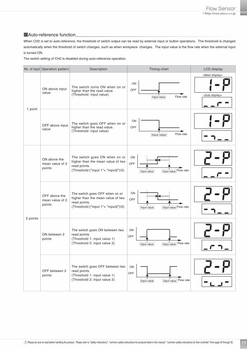
■Auto-reference functionWhen CH2 is set to auto-reference, the threshold of switch output can be read by external input or button operations. The threshold is changed automatically when the threshold of switch changes, such as when workpiece changes. The input value is the flow rate when the external input is turned ON.The switch setting of CH2 is disabled during auto-reference operation.
No. of input Operation pattern Description Timing chart LCD display
1 point
ON above input value
The switch turns ON when on or higher than the read value.(Threshold: input value) Flow rate
ON
OFF
Input value <Sub display>
<Main display>
OFF above input value
The switch goes OFF when on or higher than the read value.(Threshold: input value)
Flow rate
ON
OFF
Input value
2 points
ON above the mean value of 2 points
The switch goes ON when on or higher than the mean value of two read points.(Threshold:("input 1"+ "input2")/2) Flow rate
ON
OFF
Input value Input value
OFF above the mean value of 2 points
The switch goes OFF when on or higher than the mean value of two read points.(Threshold:("input 1"+ "input2")/2) Flow rate
ON
OFF
Input value Input value
ON between 2 points
The switch goes ON between two read points.(Threshold 1: input value 1)(Threshold 2: input value 2) Flow rate
ON
OFF
Input value Input value
OFF between 2 points
The switch goes OFF between two read points.(Threshold 1: input value 1)(Threshold 2: input value 2) Flow rate
ON
OFF
Input valueInput value
2011 NEW PRODUCTS
Please be sure to read before handling the product. Please refer to "safety instructions", "common safety instructions for products listed in this manual", "common safety instructions for flow controller" from page 24 through 35.20
■Flow direction selection (bidirectional model only)With the built-in display bidirectional model, the flow direction is selected by button operations.
Flow direction LCD display Analog output characteristic<Bidirectional>
The arrow direction changesaccording to the flow direction.
Minus “-“ indication with reverse flowdirection
〈Main display〉
〈Sub display〉
F.S. flow rate0-F.S. flow rate(Reverse direction)
anal
og o
utpu
t
(Forward direction)
5 20
3 12
1 4
(V) (mA)
(l/min)
<One-way (forward) direction>
〈Main display〉
〈Sub disply〉
(l/min)0 F.S. flow rate
5 20
3 12
1 4
(V) (mA)
(Forward direction)
anal
og o
utpu
t
<One-way (reverse) direction>
〈Main display〉
〈Sub display〉
(l/min)0 F.S. flow rate
5 20
3 12
1 4
(V) (mA)
(Reverse direction)
anal
og o
utpu
t
Flow Sensor
Please be sure to read before handling the product. Please refer to "safety instructions", "common safety instructions for products listed in this manual", "common safety instructions for flow controller" from page 24 through 35.
>>>http://www.pisco.co.jp
21
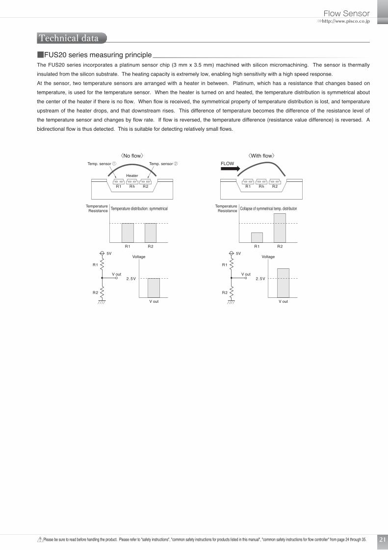
Technical data■FUS20 series measuring principleThe FUS20 series incorporates a platinum sensor chip (3 mm x 3.5 mm) machined with silicon micromachining. The sensor is thermally insulated from the silicon substrate. The heating capacity is extremely low, enabling high sensitivity with a high speed response.At the sensor, two temperature sensors are arranged with a heater in between. Platinum, which has a resistance that changes based on temperature, is used for the temperature sensor. When the heater is turned on and heated, the temperature distribution is symmetrical about the center of the heater if there is no flow. When flow is received, the symmetrical property of temperature distribution is lost, and temperature upstream of the heater drops, and that downstream rises. This difference of temperature becomes the difference of the resistance level of the temperature sensor and changes by flow rate. If flow is reversed, the temperature difference (resistance value difference) is reversed. A bidirectional flow is thus detected. This is suitable for detecting relatively small flows.
〈No flow〉
Temperature distribution: symmetrical
R1
R1
R2
R2
TemperatureResistance
Rh
Heater
R2R1
Temp. sensor ② FLOWTemp. sensor ①
〈With flow〉
Rh R2R1
V out
V out
5VVoltage
2.5V
Collapse of symmetrical temp. distributon
R1 R2
TemperatureResistance
R1
R2
V out
V out
5VVoltage
2.5V
2011 NEW PRODUCTS
Please be sure to read before handling the product. Please refer to "safety instructions", "common safety instructions for products listed in this manual", "common safety instructions for flow controller" from page 24 through 35.
P2 : Vacuum
P1 : Atmospheric pressure Suction nozzle
P1 : Pressurize
P2 : Atmospheric pressure
P1 : Pressurize
P2 : Atmospheric pressurePin hole
22
■How to select flow sensorThe following is a guide to select the flow range when using a flow sensor to verify suction and release by suction nozzle, leakage tests, and etc. The flow is calculated by the effective sectional area of nozzle (pin hole), and the pressure difference inside and outside of the nozzle.P1≧1.89P2 (sonic flow)Q=113.2×S×P1
P1<1.89P2 (subsonic flow)
Q=226.4×S× P2(P1-P2)
Q : Flow rate ℓ/minP1: Absolute primary pressure MPaP2: Absolute secondary pressure MPaS : Nozzle (pin hole) effective sectional area mm2
●Calculation exampleThe following table gives the calculated flow rate when using nozzle diameter ø0.1 to 2 with variable P2.
P1(MPa)Abs. press.
P1(MPa)Gauge press.
P2(MPa)Abs. press.
P2(MPa)Gauge press. Sonic/subsonic
Calculated flow rate (ℓ/min)
φ0.1 φ0.2 φ0.3 φ0.4 φ0.5 φ0.7 φ1 φ1.5 φ2
0.1013 0 0.0313 -0.07 Sonic 0.090 0.360 0.810 1.440 2.250 4.411 9.002 20.254 36.007
0.1013 0 0.0413 -0.06 Sonic 0.090 0.360 0.810 1.440 2.250 4.411 9.002 20.254 36.007
0.1013 0 0.0513 -0.05 Sonic 0.090 0.360 0.810 1.440 2.250 4.411 9.002 20.254 36.007
0.1013 0 0.0613 -0.04 Subsonic 0.088 0.352 0.792 1.408 2.200 4.312 8.800 19.801 35.202
0.1013 0 0.0713 -0.03 Subsonic 0.082 0.329 0.740 1.315 2.055 4.028 8.220 18.494 32.878
0.1013 0 0.0813 -0.02 Subsonic 0.072 0.287 0.645 1.147 1.792 3.512 7.166 16.125 28.666
0.1013 0 0.0913 -0.01 Subsonic 0.054 0.215 0.483 0.859 1.343 2.631 5.370 12.083 21.480
0.1113 0.01 0.1013 0 Subsonic 0.057 0.226 0.509 0.905 1.414 2.772 5.657 12.727 22.626
0.1213 0.02 0.1013 0 Subsonic 0.080 0.320 0.720 1.280 2.000 3.920 8.000 17.999 31.998
0.1413 0.04 0.1013 0 Subsonic 0.113 0.453 1.018 1.810 2.828 5.543 11.313 25.454 45.252
0.1613 0.06 0.1013 0 Subsonic 0.139 0.554 1.247 2.217 3.464 6.789 13.856 31.175 55.423
0.1813 0.08 0.1013 0 Subsonic 0.160 0.640 1.440 2.560 4.000 7.840 15.999 35.998 63.996
0.2013 0.1 0.1013 0 Sonic 0.179 0.716 1.610 2.862 4.472 8.765 17.888 40.248 71.552
0.3013 0.2 0.1013 0 Sonic 0.268 1.071 2.410 4.284 6.694 13.119 26.774 60.242 107.096
0.4013 0.3 0.1013 0 Sonic 0.357 1.426 3.209 5.706 8.915 17.474 35.660 80.236 142.641
0.5013 0.4 0.1013 0 Sonic 0.445 1.782 4.009 7.127 11.137 21.828 44.547 100.230 178.186
0.6013 0.5 0.1013 0 Sonic 0.534 2.137 4.809 8.549 13.358 26.182 53.433 120.224 213.731
(caution)・ If there is leakage in piping, etc., the actual flow will be larger than the calculated value. Please take such pipe leakage into account when
selecting the flow rate.・ If there is a section narrower than the suction nozzle diameter in piping, the flow will be restricted, and may be less than the calculated value.
It may not be possible to check suction, etc.・ The effective sectional area is a guideline. If the nozzle is long and thin, the effective sectional area will be smaller than the nozzle's opening.・ The response speed is determined and depended by the piping inner volume between the flow sensor and the suction nozzle (pin hole).
Desiring a high-speed detection, please set the flow sensor near the suction nozzle, or reduce the inner volume as much as possible.
Suct
ion
Blow
(lea
kage
insp
ectio
n)
Flow Sensor
Please be sure to read before handling the product. Please refer to "safety instructions", "common safety instructions for products listed in this manual", "common safety instructions for flow controller" from page 24 through 35.
>>>http://www.pisco.co.jp
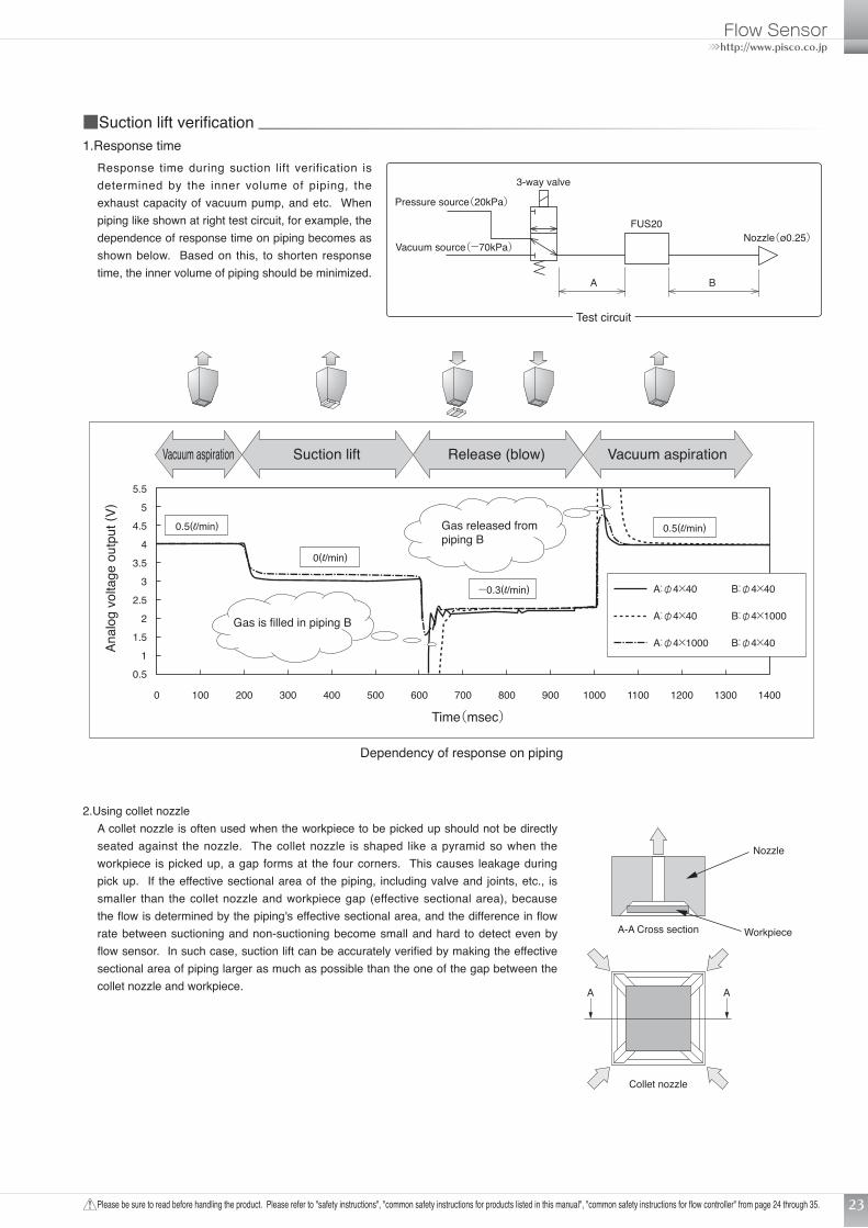
Dependency of response on piping
Vacuum aspiration Vacuum aspirationRelease (blow)Suction lift
Time(msec)
Gas is filled in piping B
5.5
5
4.5
4
3.5
3
2.5
2
1.5
1
0 100 200 300 400 500 600 700 800 900 1000 1100 1200 1300 1400
0.5
Anal
og v
olta
ge o
utpu
t (V)
Gas released frompiping B
A:φ4×40 B:φ4×40
A:φ4×40 B:φ4×1000
A:φ4×1000 B:φ4×40
0.5(l/min)
0(l/min)
0.5(l/min)
-0.3(l/min)
23
■Suction lift verification1.Response time
Response time during suction lift verification is determined by the inner volume of piping, the exhaust capacity of vacuum pump, and etc. When piping like shown at right test circuit, for example, the dependence of response time on piping becomes as shown below. Based on this, to shorten response time, the inner volume of piping should be minimized.
Pressure source(20kPa)
Nozzle(ø0.25)
A B
3-way valve
Test circuit
FUS20
Vacuum source(-70kPa)
2.Using collet nozzleA collet nozzle is often used when the workpiece to be picked up should not be directly seated against the nozzle. The collet nozzle is shaped like a pyramid so when the workpiece is picked up, a gap forms at the four corners. This causes leakage during pick up. If the effective sectional area of the piping, including valve and joints, etc., is smaller than the collet nozzle and workpiece gap (effective sectional area), because the flow is determined by the piping's effective sectional area, and the difference in flow rate between suctioning and non-suctioning become small and hard to detect even by flow sensor. In such case, suction lift can be accurately verified by making the effective sectional area of piping larger as much as possible than the one of the gap between the collet nozzle and workpiece.
A-A Cross section
Nozzle
Workpiece
Collet nozzle
A A
2011 NEW PRODUCTS
Please be sure to read before handling the product. Please refer to "safety instructions", "common safety instructions for products listed in this manual", "common safety instructions for flow controller" from page 24 through 35.24
Safety Instructions
* Safety Instructions are subject to change without advance notice.
Failure to heed the warning of apparent danger may result in death or serious injuries.
Failure to heed the warning of conditionally dangerous situations may result in death or serious injuries.
Failure to heed the warning of conditionally dangerous situations may result in minor or not too serious injuries or damage to properties.
This Safety Instructions aim to prevent injuries to human bodies and damage to properties by requiring proper use of PISCO devices.Also the relevant requirements of ISO 4414 and JIS B8370 must be observed.ISO 4414: Pneumatic fluid power … Recomendations for the application of equipment to transmission and control systems.JIS B 8370: General standards for pneumatic systemsSafety instructions are classified into "Danger", "Warning" and "Caution", depending on the degree of danger or damage involved when the safety instructions are not complied with in handling the equipment.
Danger
Warning
CautionWarnings : 1. Make a selection of pneumatic equipment.
(1) Well knowledgeable and experienced persons such as a pneumatic system designer or who is in charge of deciding specification should select pneumatic equipment.
(2) The applicable conditions of the products in this catalogue are diverse. Therefore, judge the conformity of systems with required analysis or tests by system designers or persons who is in charge of deciding specifications. The guarantee of initial performance and safety of the system is on responsibility of the person who decides specifications. Hereafter, examine all the specification with updated products catalogues and technical documents in order to avoid malfunctions of equipment, and then develop systems.
2. Handle pneumatic equipment with enough knowledge and experience.(1) Mishandling of compressed air is dangerous. Conduct assembly, operation and maintenance of devises with pneumatic
equipment by persons with enough knowledge and experience.3. Do not operate and remove the equipment until safety is confirmed.
(1) Conduct inspection and maintenance of equipment after confirming fail-proof measures of work pieces or runaway-proof device are properly working.
(2) When removing equipment, make sure that above safety measures are conducted. Then, stop air supply and electric source of equipment making sure the pressure inside the system is zero before removing equipment.
(3) When re-activate equipment, make sure safety measures against fly-out are taken and re-activate equipment with care.
Disclaimer1. We take no responsibility whatsoever for any incidental and indirect damages (e.g. manufacturing line stop, business interruption, loss of
profit and physical injury) caused by the use or defect in use of PISCO devices.2. We take no responsibility whatsoever for the device failure damage caused by natural disaster, fire, except fire responsible to us, act by a
third party and intention or negligence by customers.3. We take no responsibility whatsoever for the damage caused by uses beyond the range of specification described in our catalogues and
handling instructions.4. We take no responsibility whatsoever for the damage caused by the re-creation of devices and the failure from the combinations of
software and connected equipment.5. We pay the damage for the failure caused by PISCO devises up to a ceiling of the purchased Pisco devise expense.
Flow Sensor>>>http://www.pisco.co.jp
Please be sure to read before handling the product. Please refer to "safety instructions", "common safety instructions for products listed in this manual", "common safety instructions for flow controller" from page 24 through 35. 25
Common Safety Instructions for Products Listed in This Manual
Danger : 1. Do not use PISCO devices with the following equipment:(1) Equipment used for the sustenance or control of people's health or lives(2) Equipment used for the movement or transport of people(3) Equipment used specifically to ensure safety
Warnings : 1. Avoid the following uses for PISCO devices:(1) Use under conditions not specified for the device.(2) Use at outdoors, or at a place getting the direct sunlight.(3) Use in locations where the device is exposed to excessive vibration or shocks.(4) Use in locations where the device is exposed to any corrosive gas, inflammable gas, chemicals, seawater, or vapor.
* Certain PISCO devices, however, can be used in environments as described above. Therefore check on the specifications for the use of individual devices.
2. Do not disassemble or remodel the PISCO devices in such a way as may affect the basic structure, performance or function of them.
3. The maintenance check of product should be performed after turning the power off, stopping air supply, and confirming that the pressure inside the plumbing becomes zero.
4. Never touch the release ring of the Quick-Fitting Joint when there is pressure working on it. Touching may release the ring, which in turn may cause the tube to fall out.
5. Avoid too frequent switching of air pressure. Otherwise the device body may heat up to cause burns on you.6. Do not allow tension, twist or bending forces to act on the products. Undue forces may damage theproducts.7. For applications in which the threaded side or the tube connection side is subject to swinging or rotation, use Rotary Joints,
High Rotary Joints or Multi-Circuit Rotary Blocks only. Swinging or rotation may damage the joint body.8. Except for Die Temp. Control Fitting, Tube Fitting Stainless SUS316, SUS316 Compression Fitting, and All Brass Compression
Fitting, please do not use products with hot water or thermal oil over 60ºC. There is danger to cause the damage of the main body of product by heat and hydrolysis.
9. For applications in which the scattering of static electricity or charging must be prevented, use no other joints than EG (anti-static) specification products. Static electricity may cause system malfunction or trouble.
10. Never use joint other than Spatter spec. products or all metal products where they are exposed to spatter. Otherwise spatter can cause fire.
11. Carry out maintenance and checks of equipment only after turning power off, shutting fluid off and making certain that the pressure in the piping has dropped to zero. Please conduct maintenance after confirming following points. (1) Make sure that maintenance is safe for all systems involving PISCO products. (2) When re-activate equipment after maintenance, make sure safety measures against fly-out are taken and re-activate
equipment with care.(3) Please secure space for maintenance when the circuit is designed.
12. When the fluid is admitted to the equipment and if there is a possibility to cause damage to it due to leakage, conduct safety measures such as protective cover beforehand.
PISCO products are designed and manufactured for use with general industrial machinery and equipment. Therefore be sure to observe the following safety instructions:
2011 NEW PRODUCTS
Please be sure to read before handling the product. Please refer to "safety instructions", "common safety instructions for products listed in this manual", "common safety instructions for flow controller" from page 24 through 35.26
Tube end
Elastic-sleeve seal
In case that tube is not inserted to tubeend completely
mm size Nylon tube Urethane tube ø1.8mm – ±0.05mm ø3mm – ±0.15mm ø4mm ±0.1mm ±0.15mm ø6mm ±0.1mm ±0.15mm ø8mm ±0.1mm ±0.15mm ø10mm ±0.1mm ±0.15mm ø12mm ±0.1mm ±0.15mm ø16mm ±0.1mm ±0.15mm
Table 1. Tube O.D. Tolerance inch size Nylon tube Urethane tube ø1/8in. ±0.1mm (0.0039in.) ±0.15mm (0.0059in.) ø5/32in. ±0.1mm (0.0039in.) ±0.15mm (0.0059in.) ø3/16in. ±0.1mm (0.0039in.) ±0.15mm (0.0059in.) ø1/4in. ±0.1mm (0.0039in.) ±0.15mm (0.0059in.) ø5/16in. ±0.1mm (0.0039in.) ±0.15mm (0.0059in.) ø3/8in. ±0.1mm (0.0039in.) ±0.15mm (0.0059in.) ø1/2in. ±0.1mm (0.0039in.) ±0.15mm (0.0059in.) ø5/8in. ±0.1mm (0.0039in.) ±0.15mm (0.0059in.)
6. Cautions on the fitting of tube(1) Make certain that the end of the tube is cut at right angles, the tube surface is free from flaws, and the tube is not deformed
into an ellipse.(2) When fitting a tube, refer to the dimensional specification of Table 2. To prevent leaks, insert the tube to end completely.(3) On completion of fitting, make certain that the tube does not come out at your pulling.* At the time of installing a tube on a fitting, although it is hard to identify the lock-claws by looking into release-ring hole, tube
not always looses. Most of causes of loosing tube are ① shear drop of fore-end of lock-claws and ② abnormal (small) tube outer diameter. Therefore, please insert the tube following the procedure of fitting of tube (1) to (3) even if the lock-claws is not observed.
7. Cautions on the release of tube(1) Before releasing the tube, make certain that the pressure inside the tube is zero.(2) Push the release ring fully inside and pull out the tube. Unless you push it completely in, the tube may not come out and
scrapings of tube may be left inside the joint.
Cautions : 1. In installing the piping, be sure to remove dust or drainage from the inside of piping. Dust or drainage left unremoved may enter other equipment, thus causing troubles.
2. When using an ultrasoft tube to connect to a Quick-Fitting Joint, be sure to use an insert ring in the bore of the tube. Otherwise the tube may fall out to cause leakage.
3. A crack occurs under the influence of ozone and causes malfunction if NBR is used as material of a seal rubber, a vacuum pad, and a gasket. Ozone usually exists in high density near neutralization air, a cleanroom, a high voltage motor, etc. The change of rubber materials to HNBR or FKM is necessary for measures. Please consult nearest Pisco sales office for the details.
4. The infinitesimal leakage may be produced on the product with oil-free specifications. If a fluid medium is liquid or an application require something severe condition, please consult nearest Pisco office.
5. When you use tubes of brands other than ours, be sure to confirm that the outside diameter of the tubes satisfies the tolerance specified Table 1.
Flow Sensor>>>http://www.pisco.co.jp
Please be sure to read before handling the product. Please refer to "safety instructions", "common safety instructions for products listed in this manual", "common safety instructions for flow controller" from page 24 through 35. 27
Common Safety Instructions for Products Listed in This Manual
Thread type Thread size Tightening torque Sealock color Gasket material M3×0.5 0.7N·m M5×0.8 1 ~ 1.5N·m SUS304, NBR M6×1 2 ~ 2.7N·m – Metric thread M3×0.5 0.5 ~ 0.6N·m M5×0.8 1 ~ 1.5N·m POM M6×0.75 0.8 ~ 1N·m M8×0.75 1 ~ 2N·m R1/8 7 ~ 9N·m Taper pipe thread R1/4 12 ~ 14N·m
White – R3/8 22 ~ 24N·m R1/2 28 ~ 30N·m Unified thread No. 10-32UNF 1 ~ 1.5N·m – SUS304, NBR 1/16-27NPT 7 ~ 9N·m Pipe thread 1/8-27NPT 7 ~ 9N·m General purpose 1/4-18NPT 12 ~ 14N·m White – (inch) 3/8-18NPT 22 ~ 24N·m 1/2-14NPT 28 ~ 30N·m*.Since it may different by product, please also refer to the detailed safety instruction of each product.
Table 2. Tightening Torque, Sealock Color and Gasket Material
8. Cautions on the installation of joint body(1) For installation of a product, please tighten it with a proper tool using outer hexagonal part or internal hexagonal part.
Please pay attention that the tool and lock-claws are not come in contact when inserting the tool into hexagonal hole. The loss of tube lock function may be caused by deformation of fore-end of lock-claws and may cause loosing tube.(2) In tightening the screw, use the tightening torque recommended in Table 2.
・Use of a torque higher than the recommended level may damage thread or deform gasket, thus causing leaks.・Use of a torque lower than the recommended level may cause loose screw and leakage.
(3) With the joint whose piping direction will not change after tightening, make adjustment within the recommended range of tightening torques.
9. Cautions on the removal of joint body(1) When removing the joint body, loosen it with a proper tool, using the outside or inside hexagon.(2) Remove sealant sticking to the thread on the mating equipment. The sealant left sticking may enter the peripheral equipment
and cause trouble.10. Please make plumbing so that torsion, tension, moment load, vibration, and a shock are strained to tube and fitting. If not,
damage to a fitting, or squashed, burst or loosen tube may be caused.
2011 NEW PRODUCTS
Please be sure to read before handling the product. Please refer to "safety instructions", "common safety instructions for products listed in this manual", "common safety instructions for flow controller" from page 24 through 35.28
Common Safety Instructions for Flow Controller
Warnings : 1. The products are designed and manufactured as parts for general industrial machines. Therefore, the person that has sufficient knowledge and experience must handle them.
2. Please make sure to use the products within the specifications range. It is not allowed to use the products outside the specifications range. Please do not attempt to modify or additionally machine
the products. Because the products are designed and manufactured as parts for general industrial machines, it is not approved when using it outdoors, and when using it under the conditions and environment below.(1) Use for special applications requiring safety including nuclear energy, railroad, aviation, ship, vehicle, medical equipment,
equipment or components directly contacting to beverage, food, etc., amusement equipment, emergency shutoff circuits, press machines, brake circuits, safeguard, etc.
(2) Use for applications where life or assets could be adversely affected, and special safety measure are required.3. For the safety on equipment design/control, etc., corporate standards, regulations, and etc., must be observed. ISO4414 and JIS B 8370 (pneumatic system rules) JFPS2008 (principles for use and selections of pneumatic cylinder) High Pressure Gas Maintenance Law, Occupational Safety and Sanitation Laws, other safety regulations, corporate standards,
and etc.4. Please do not handle the products, plumbing, nor remove components before confirming safety.
(1) Please inspect and service the machines and devices after confirming safety of the entire system related this product. (2) Care must be taken even after operation is stopped since it may be hot or there may be charged section.(3) When inspecting or servicing the device, please turn off the energy source (pneumatic or hydraulic source), and turn off
power to the facility. Please discharge the residual pressure and pay special attention to possible leakages of water and electricity.
(4) When starting and restarting a machine or device using pneumatic components, please make sure the system safety, such as popping-out prevention measures and etc. is secured.
5. Warning and cautions on the following pages must be observed to prevent accidents.
■In order to use the sensor safelyPlease always read this instruction before starting use.When designing and manufacturing a device using PISCO products, the manufacturer is obligated to check that device safety mechanism, pneumatic control circuit, or water control circuit and the system operated by electrical control that controls the devices is secured.It is important to select, use, handle or maintain the product appropriately to ensure that PISCO products are used safely.Please observe warning and cautions to ensure the safety of equipment.Please check that the safety of equipment be ensured, then manufacture safe equipment.
Flow Sensor>>>http://www.pisco.co.jp
Please be sure to read before handling the product. Please refer to "safety instructions", "common safety instructions for products listed in this manual", "common safety instructions for flow controller" from page 24 through 35. 29
■Warning/cautions at the time of design & selection1. Fluid mediumDanger
■ A flammable fluid must not be used.
Warnings■ The product can not be used as a business meter. Since it is not conformed to the Measurement Law, please do not use the product for the commercial purpose. Please use the product
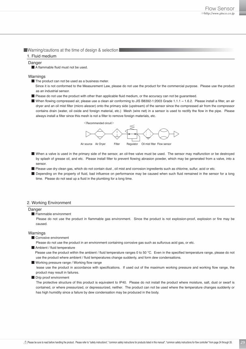
as an industrial sensor.■ Please do not use the product with other than applicable fluid medium, or the accuracy can not be guaranteed.■ When flowing compressed air, please use a clean air conforming to JIS B8392-1:2003 Grade 1.1.1 ~ 1.6.2. Please install a filter, an air
dryer and an oil mist filter (micro alescer) onto the primary side (upstream) of the sensor since the compressed air from the compressor contains drain (water, oil oxide and foreign material, etc.) Mesh (wire net) in a sensor is used to rectify the flow in the pipe. Please always install a filter since this mesh is not a filter to remove foreign materials, etc.
<Recommended circuit>
Air source Air Dryer Filter Regulator Oil mist filter Flow sensor
2. Working EnvironmentDanger
■ Flammable environment Please do not use the product in flammable gas environment. Since the product is not explosion-proof, explosion or fire may be
caused.
Warnings■ Corrosive environment Please do not use the product in an environment containing corrosive gas such as sulfurous acid gas, or etc.■ Ambient / fluid temperature Please use the product within the ambient / fluid temperature ranges 0 to 50 °C. Even in the specified temperature range, please do not
use the product where ambient / fluid temperatures change suddenly, and form dew condensations.■ Working pressure range / Working flow range lease use the product in accordance with specifications. If used out of the maximum working pressure and working flow range, the
product may result in failures.■ Drip proof environment The protective structure of this product is equivalent to IP40. Please do not install the product where moisture, salt, dust or swarf is
contained, or where pressurized, or depressurized, neither. The product can not be used where the temperature changes suddenly or has high humidity since a failure by dew condensation may be produced in the body.
■ When a valve is used in the primary side of the sensor, an oil-free valve must be used. The sensor may malfunction or be destroyed by splash of grease oil, and etc. Please install filter to prevent flowing abrasion powder, which may be generated from a valve, into a sensor.
■ Please use dry clean gas, which do not contain dust , oil mist and corrosion ingredients such as chlorine, sulfur, acid or etc.■ Depending on the property of fluid, bad influence on performance may be caused when such fluid remained in the sensor for a long
time. Please do not seal up a fluid in the plumbing for a long time.
2011 NEW PRODUCTS
Please be sure to read before handling the product. Please refer to "safety instructions", "common safety instructions for products listed in this manual", "common safety instructions for flow controller" from page 24 through 35.30
3. Flow rate unitCaution
■ The flow rate of this product is measured by mass flow not depended with temperature and pressure. Unit is L/min where mass flow is converted to volumetric flow at 20°C and 1 atmospheric pressure (101kPa).
4. OverflowCaution
■ Even if twice as much overflow as each series measuring range is applied to the sensor, it is no problem, however, if dynamic pressure is applied near to the maximum working pressure (when the pressure applied to the primary side with the secondary side released), the sensor may fail. If dynamic pressure is applied such as feeding workpiece during leakage inspection, please always provide a by-pass circuit or a needle valve to avoid applying dynamic pressure to the sensor.
5. Suction lift verification, etc.Cautions
■ When using this product with suction lift verification, etc., select the flow rate range according to vacuum range and vacuum nozzle diameter. Refer to Page 22 “How to select flow sensor.”
■ When using this product with suction lift verification, etc., please always install an air filter onto the upstream of suction side to prevent suction of foreign materials.
■ When using this product with suction lift verification, etc., considering atmospheric dew point and ambient temperature of this product, please use the product under the conditions that dew condensations will not be formed in the inside of pipe.
■ When using this product with suction lift verification, etc., response time may delay per piping volume between the sensor and vacuum nozzle. In that case, please take measures such as, reducing piping volume, etc.
■ When using the product with vacuum applications such as air aspiration, etc., please do not bend the tube near the quick-fitting. If stress is applied to the tube near the quick-fitting, please insert the tube into the quick-fitting after inserting the insert-ring.
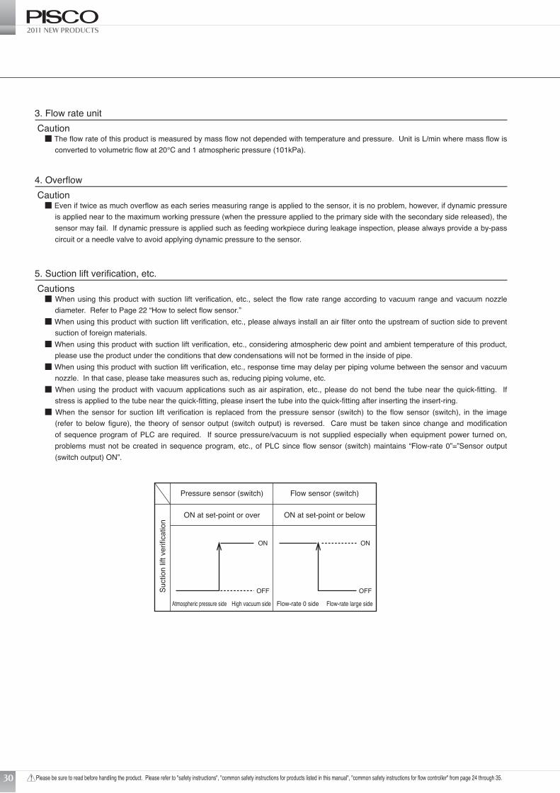
■ When the sensor for suction lift verification is replaced from the pressure sensor (switch) to the flow sensor (switch), in the image (refer to below figure), the theory of sensor output (switch output) is reversed. Care must be taken since change and modification of sequence program of PLC are required. If source pressure/vacuum is not supplied especially when equipment power turned on, problems must not be created in sequence program, etc., of PLC since flow sensor (switch) maintains “Flow-rate 0”=”Sensor output (switch output) ON”.
Pressure sensor (switch) Flow sensor (switch)
ON at set-point or over
Atmospheric pressure side
ON
OFF
High vacuum side Flow-rate 0 side Flow-rate large side
ON at set-point or below
ON
OFFSuct
ion
lift v
erifi
catio
n
Flow Sensor>>>http://www.pisco.co.jp
Please be sure to read before handling the product. Please refer to "safety instructions", "common safety instructions for products listed in this manual", "common safety instructions for flow controller" from page 24 through 35. 31
Common Safety Instructions for Products Listed in This Manual
■Warning/cautions of installation & adjustment1. PipingCautions
■ Installation and plumbing must be done prior to wiring.■ It must be piped, while matching the flow direction and direction specified on the body.■ Please flash the pipe by air blow to remove foreign substances and swarf, etc., in inside of pipe before piping. If many foreign materials
and swarf, etc. entrain into the inside, the rectifier and the sensor tip could be damaged.■ If a quick-fitting is used, the tube must be inserted certainly. Please pulls the tube to check that it will not come out. Cut the tube at the
right angle with the dedicating cutter.
2. InstallationCautions
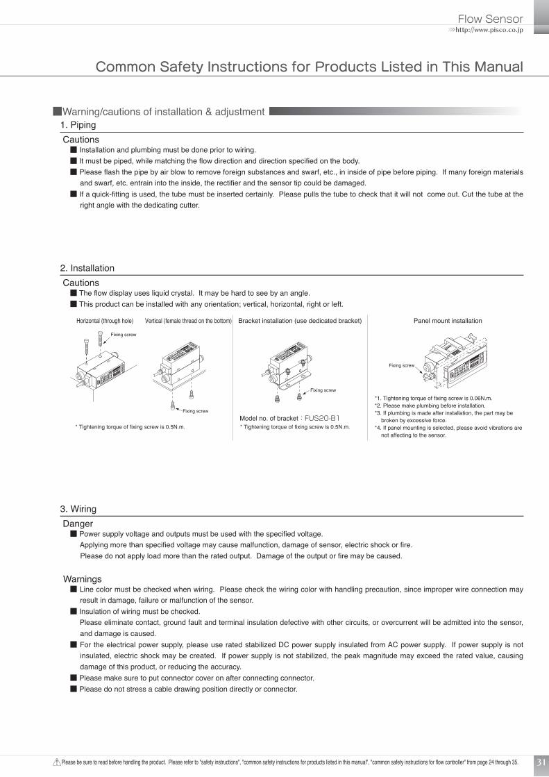
■ The flow display uses liquid crystal. It may be hard to see by an angle.■ This product can be installed with any orientation; vertical, horizontal, right or left.
Horizontal (through hole) Bracket installation (use dedicated bracket)Vertical (female thread on the bottom)
Model no. of bracket:FUS20-B1
Fixing screw
Fixing screw
Fixing screw
* Tightening torque of fixing screw is 0.5N.m. * Tightening torque of fixing screw is 0.5N.m.
Panel mount installation
Fixing screw
*1. Tightening torque of fixing screw is 0.06N.m.*2. Please make plumbing before installation.*3. If plumbing is made after installation, the part may be
broken by excessive force.*4. If panel mounting is selected, please avoid vibrations are
not affecting to the sensor.
3. WiringDanger
■ Power supply voltage and outputs must be used with the specified voltage. Applying more than specified voltage may cause malfunction, damage of sensor, electric shock or fire. Please do not apply load more than the rated output. Damage of the output or fire may be caused.
Warnings■ Line color must be checked when wiring. Please check the wiring color with handling precaution, since improper wire connection may
result in damage, failure or malfunction of the sensor.■ Insulation of wiring must be checked. Please eliminate contact, ground fault and terminal insulation defective with other circuits, or overcurrent will be admitted into the sensor,
and damage is caused.■ For the electrical power supply, please use rated stabilized DC power supply insulated from AC power supply. If power supply is not
insulated, electric shock may be created. If power supply is not stabilized, the peak magnitude may exceed the rated value, causing damage of this product, or reducing the accuracy.
■ Please make sure to put connector cover on after connecting connector.■ Please do not stress a cable drawing position directly or connector.
2011 NEW PRODUCTS
Please be sure to read before handling the product. Please refer to "safety instructions", "common safety instructions for products listed in this manual", "common safety instructions for flow controller" from page 24 through 35.32
■ For wiring, please stop control unit, machinery and equipment, and turn off the power supply first. Drastic operation may lead to unexpected motions, causing a danger. First, please attempt energizing test, then set the desired switch data while control unit, machinery and equipment are stopped. Please discharge static electricity builted in body, tool and equipment before and during work. Use a wire with elasticity as wire for robot connection in the movable part.
■ Please do not use the product beyond the power supply voltage range. If voltage more than its range is applied, or if alternating current power (100VAC) is applied, it may cause a damage or burn.
■ This product and wiring must be installed as far away as possible from noise source such as strong electric line, etc. Please take other countermeasures for a surge on the power supply line.
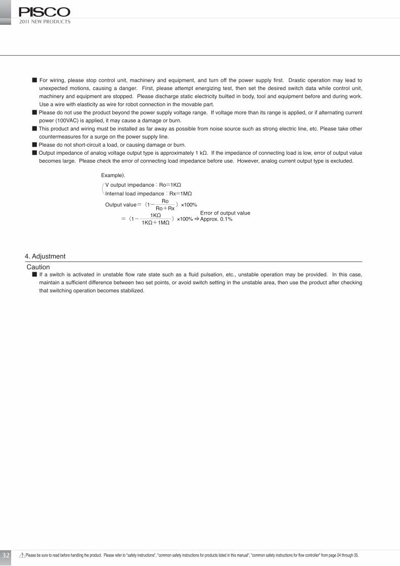
■ Please do not short-circuit a load, or causing damage or burn.■ Output impedance of analog voltage output type is approximately 1 kΩ. If the impedance of connecting load is low, error of output value
becomes large. Please check the error of connecting load impedance before use. However, analog current output type is excluded.
V output impedance : Ro=1KΩInternal load impedance : Rx=1MΩ
Output value=(1- )×100%RoRo+Rx
=(1- )×100%1KΩ1KΩ+1MΩ
Error of output valueApprox. 0.1%
Example).
4. AdjustmentCaution
■ If a switch is activated in unstable flow rate state such as a fluid pulsation, etc., unstable operation may be provided. In this case, maintain a sufficient difference between two set points, or avoid switch setting in the unstable area, then use the product after checking that switching operation becomes stabilized.
Flow Sensor>>>http://www.pisco.co.jp
Please be sure to read before handling the product. Please refer to "safety instructions", "common safety instructions for products listed in this manual", "common safety instructions for flow controller" from page 24 through 35. 33
Common Safety Instructions for Products Listed in This Manual
■Usage and MaintenanceWarnings
■ Output accuracy is affected by self-heating caused by energizing other than temperature characteristics. At the time of usage, stand-by time (over 5 minutes after energization) must be provided.
■ For self-diagnosis, this product does not conduct flow rate detecting switch operation for about 4 seconds immediately after energized. Please make a control circuit and programs to ignore signals for about 4 seconds after energized.
Cautions■ When an error occurs during operation, please turn off power supply immediately, and terminate the operation, and contact to the sales
office.■ Use the product within range of rated flow.■ Use the product within range of working pressure.■ When changing set points of the output, please stop the equipment, then change the set points, or an accident may occur.■ A periodic inspection should be done at least once a year, then please make sure that the product be operated properly.■ Disassembly and modification must not be done or causing a failure.■ The material of case is resin. Solvent/alcohol/cleaner, etc., must not be used to remove contamination, etc., or causing a resin to be
corroded. Please wipe with diluted neutral detergent by tightly squeezed waste cloth, etc.■ Please be careful of reverse current by disconnection/wiring resistance. If other components including other flow sensors are
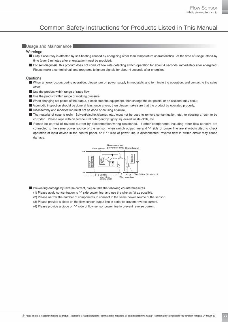
connected to the same power source of the sensor, when switch output line and "-" side of power line are short-circuited to check operation of input device in the control panel, or if "-" side of power line is disconnected, reverse flow in switch circuit may cause damage.
Current from other components
Test SW or Short circuitDisconnection
Flow sensor Control panelReverse currentprevention diode
Mai
nC
ircui
t
Oth
er
comp
onen
ts
PLC
input
■ Preventing damage by reverse current, please take the following countermeasures. (1) Please avoid concentration to "-" side power line, and use the wire as fat as possible. (2) Please narrow the number of components to connect to the same power source of the sensor. (3) Please provide a diode on the flow sensor output line in serial to prevent reverse current. (4) Please provide a diode on "-" side of flow sensor power line to prevent reverse current.
2011 NEW PRODUCTS
Please be sure to read before handling the product. Please refer to "safety instructions", "common safety instructions for products listed in this manual", "common safety instructions for flow controller" from page 24 through 35.34
Inpu
tco
mpo
nent
s
Inpu
tco
mpo
nent
s
Inpu
tco
mpo
nent
s
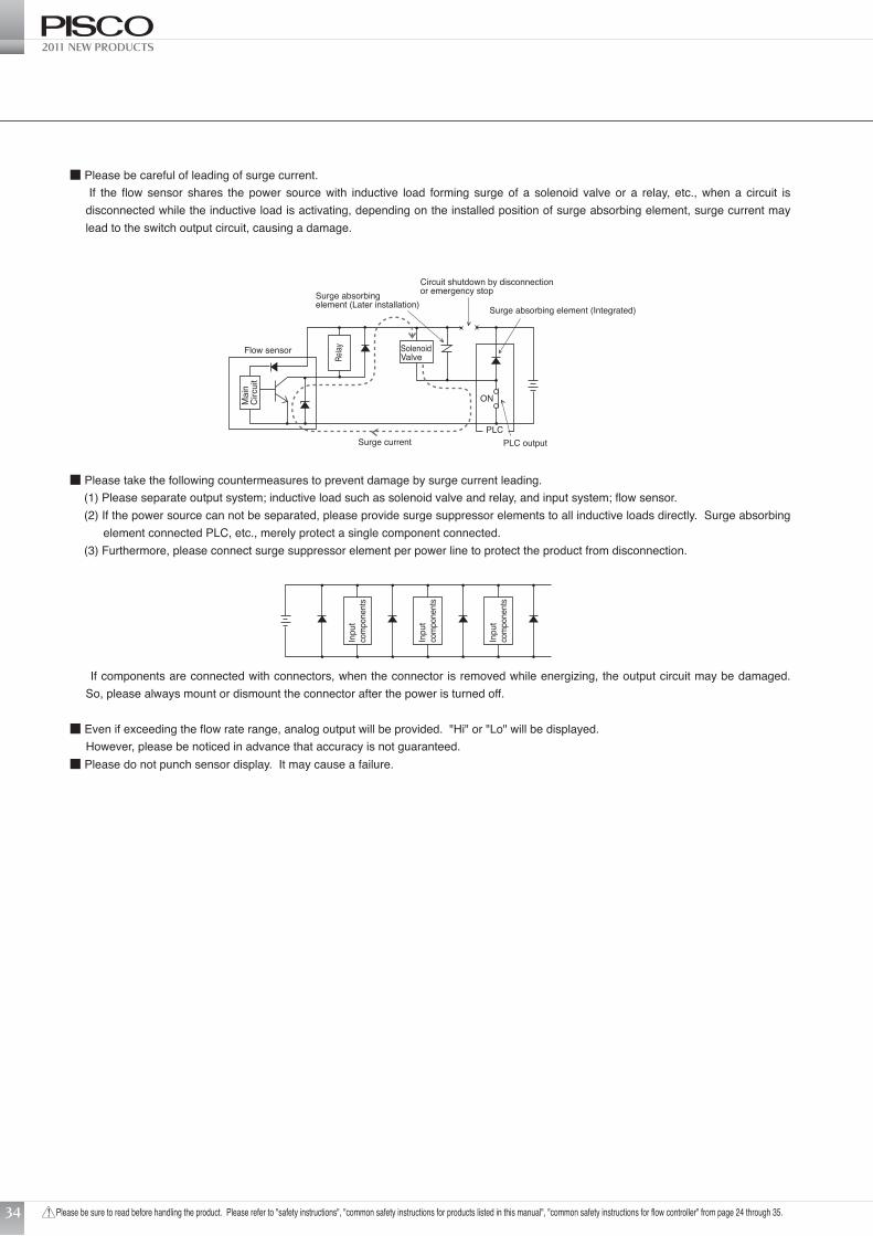
■ Please take the following countermeasures to prevent damage by surge current leading.(1) Please separate output system; inductive load such as solenoid valve and relay, and input system; flow sensor.(2) If the power source can not be separated, please provide surge suppressor elements to all inductive loads directly. Surge absorbing
element connected PLC, etc., merely protect a single component connected.(3) Furthermore, please connect surge suppressor element per power line to protect the product from disconnection.
Surge absorbing element (Integrated)
Circuit shutdown by disconnectionor emergency stopSurge absorbing
element (Later installation)
Flow sensor
Surge current PLC outputPLC
ONMai
nC
ircui
t
Relay Solenoid
Valve
■ Please be careful of leading of surge current. If the flow sensor shares the power source with inductive load forming surge of a solenoid valve or a relay, etc., when a circuit is
disconnected while the inductive load is activating, depending on the installed position of surge absorbing element, surge current may lead to the switch output circuit, causing a damage.
If components are connected with connectors, when the connector is removed while energizing, the output circuit may be damaged. So, please always mount or dismount the connector after the power is turned off.
■ Even if exceeding the flow rate range, analog output will be provided. "Hi" or "Lo" will be displayed. However, please be noticed in advance that accuracy is not guaranteed.■ Please do not punch sensor display. It may cause a failure.

Flow Sensor>>>http://www.pisco.co.jp
Please be sure to read before handling the product. Please refer to "safety instructions", "common safety instructions for products listed in this manual", "common safety instructions for flow controller" from page 24 through 35. 35
Common Safety Instructions for Products Listed in This Manual
■Detailed Safety Instruction of built-in needle valve flow sensor1. Design & selectionCautions
■ The product cannot be used as shut-off valve requiring no leakage. A certain degree of leakage is allowed as specifications.■ Please select and use a clean filter scch as hollow fiber membrane filter (MFU) or etc. if dusts and particles, which are generated in a
flow path of needle valve, causes a problem.
2. Installation & adjustmentCaution
■ Please do not turn the needle with excessive force at the time of full open or close (Max. 0.05N.m). Please do not turn the needle with holding a rock nut. It may cause galling or breakage of needle.
3. Usage and maintenaceCaution
■ The flow rate may change by needle rotation caused by vibrations.

OVERSEAS OPERATION TEAM3884-1, MINAMIMINOWA, KAMIINA, NAGANO-PREF., 399-4588 JAPANTel. +81-(0)265-76-7751 Fax. +81-(0)265-76-3305 Website. http://www.pisco.co.jp/english/pisco.htm E-mail. [email protected]
●The specifications are subject to change without advance notice. 2012.02.PDF