FLOW CONTROL - Griswold Controls
16
INSTALLATION & OPERATION INSTRUCTIONS FLOW CONTROL Replaces form F-709N, F-2049, F-2425, F-4030, F-4045, F-4047, F-4273, F-5485 Page 9/16 This specification © 2016 Griswold Controls F-709ZE 2803 Barranca Parkway, Irvine, CA 92606 (949) 559-6000 Fax (949) 559-6088 www.GriswoldControls.com 1 IMPORTANT NOTE! Please take the time to read this instruction sheet. Disregarding these guidelines may adversely affect your piping components GENERAL INFORMATION ....................................................................................................................................... 1 O-RING REPLACEMENT.......................................................................................................................................... 2 CLEANING ................................................................................................................................................................ 3 ALTERNATE FLUIDS................................................................................................................................................ 3 INSTALLATION GUIDELINES .................................................................................................................................. 3 Threaded Valves ............................................................................................................................................... 3 ProPress Valves with Smart Connect™ Feature........................................................................................... 3 Sweat Valves ..................................................................................................................................................... 3 Flanged Valves ................................................................................................................................................. 4 Grooved End Valves ........................................................................................................................................ 4 Weld End Valves............................................................................................................................................... 5 Actuator Operated Valves ............................................................................................................................... 5 Actuator Wiring Diagrams ............................................................................................................................... 6 Hoses ................................................................................................................................................................. 7 VERIFYING THE FLOWRATE .................................................................................................................................. 9 Automatic Flow Limiting Valves ..................................................................................................................... 9 Pressure Independent Valves ......................................................................................................................... 9 Manual Balance Valves (QuickSet® and QuickDisc™) .............................................................................. 10 Manual Balance Valve Meter Kit ................................................................................................................... 10 CARTRIDGE REMOVAL ......................................................................................................................................... 11 IsolatorR, IsolatorY, Automizer®, K Valve, PIC-V®, Uni-Flange ......................................................... 11 Threaded Mini, Combo Valve ........................................................................................................................ 11 Wafer, Grooved End, Flange End ................................................................................................................. 11 BALL VALVE STEM REMOVAL.............................................................................................................................. 12 Handle Operated Stem................................................................................................................................... 12 Actuator Operated Stem (Non Direct Mount) .............................................................................................. 12 Actuator Operated Stem (Direct Mount) ...................................................................................................... 13 REPLACING THE SEALS AND O–RINGS ............................................................................................................. 14 Unimizer® (1/2” - 3”) ...................................................................................................................................... 14 Automizer/PIC–V............................................................................................................................................. 15 TROUBLE SHOOTING VALVES ............................................................................................................................ 15 WARRANTY ............................................................................................................................................................ 16 Griswold Controls assumes no responsibility for damages or injuries resulting from non-compliance with installation instructions or standard good practice when installing, operating, or maintaining the valves, even if not explicitly mentioned in the installation instructions. Griswold Controls uses many quality control checkpoints during its manufacturing process. Handling during transport, unpacking or installation can alter a product’s performance, including joint connections. If torque is applied to the product during installation, dope will crack and a leak may occur. We rely on you as professional contractors to inspect, install and perform a thorough test during startup to correct any adverse handling or installation conditions that may affect the performance of the product. Thank you for your assistance. GENERAL INFORMATION 1. Griswold Controls’ valves MAY contain drain valves and/or combination P/T test valve and manual air vent (CPTA). You can identify the CPTA because the sticker on top says “NO TAPE DOPE” Both types of accessory components have a straight thread and do not require any pipe dope or tape sealant. Using pipe dope or sealant may cause problems with the seal and may clog the hole in the housing that is used to vent air with the CPTA. Extensions for these components also have a straight thread. Drain CPTA
Transcript of FLOW CONTROL - Griswold Controls
INSTALLATION & OPERATION INSTRUCTIONS FLOW CONTROL
Replaces form F-709N, F-2049, F-2425, F-4030, F-4045, F-4047, F-4273, F-5485 Page 9/16 This specification © 2016 Griswold Controls F-709ZE
2803 Barranca Parkway, Irvine, CA 92606 (949) 559-6000 Fax (949) 559-6088 www.GriswoldControls.com
1
IMPORTANT NOTE! Please take the time to read this instruction sheet.
Disregarding these guidelines may adversely affect your piping components GENERAL INFORMATION ....................................................................................................................................... 1 O-RING REPLACEMENT .......................................................................................................................................... 2 CLEANING ................................................................................................................................................................ 3 ALTERNATE FLUIDS ................................................................................................................................................ 3 INSTALLATION GUIDELINES .................................................................................................................................. 3
Threaded Valves ............................................................................................................................................... 3 ProPress Valves with Smart Connect™ Feature ........................................................................................... 3 Sweat Valves ..................................................................................................................................................... 3 Flanged Valves ................................................................................................................................................. 4 Grooved End Valves ........................................................................................................................................ 4 Weld End Valves ............................................................................................................................................... 5 Actuator Operated Valves ............................................................................................................................... 5 Actuator Wiring Diagrams ............................................................................................................................... 6 Hoses ................................................................................................................................................................. 7
VERIFYING THE FLOWRATE .................................................................................................................................. 9 Automatic Flow Limiting Valves ..................................................................................................................... 9 Pressure Independent Valves ......................................................................................................................... 9 Manual Balance Valves (QuickSet® and QuickDisc™) .............................................................................. 10 Manual Balance Valve Meter Kit ................................................................................................................... 10
CARTRIDGE REMOVAL ......................................................................................................................................... 11
IsolatorR, IsolatorY, Automizer®, K Valve, PIC-V®, Uni-Flange ......................................................... 11 Threaded Mini, Combo Valve ........................................................................................................................ 11 Wafer, Grooved End, Flange End ................................................................................................................. 11
BALL VALVE STEM REMOVAL .............................................................................................................................. 12 Handle Operated Stem ................................................................................................................................... 12 Actuator Operated Stem (Non Direct Mount) .............................................................................................. 12 Actuator Operated Stem (Direct Mount) ...................................................................................................... 13
REPLACING THE SEALS AND O–RINGS ............................................................................................................. 14 Unimizer® (1/2” - 3”) ...................................................................................................................................... 14 Automizer/PIC–V............................................................................................................................................. 15
TROUBLE SHOOTING VALVES ............................................................................................................................ 15 WARRANTY ............................................................................................................................................................ 16
Griswold Controls assumes no responsibility for damages or injuries resulting from non-compliance with installation instructions or standard good practice when installing, operating, or maintaining the valves, even if not explicitly mentioned in the installation instructions.
Griswold Controls uses many quality control checkpoints during its manufacturing process. Handling during transport, unpacking or installation can alter a product’s performance, including joint connections. If torque is applied to the product during installation, dope will crack and a leak may occur. We rely on you as professional contractors to inspect, install and perform a thorough test during startup to correct any adverse handling or installation conditions that may affect the performance of the product. Thank you for your assistance.
GENERAL INFORMATION 1. Griswold Controls’ valves MAY contain drain valves and/or combination P/T test valve and
manual air vent (CPTA). You can identify the CPTA because the sticker on top says “NO TAPE DOPE” Both types of accessory components have a straight thread and do not require any pipe dope or tape sealant. Using pipe dope or sealant may cause problems with the seal and may clog the hole in the housing that is used to vent air with the CPTA. Extensions for these components also have a straight thread.
Drain CPTA
INSTALLATION & OPERATION INSTRUCTIONS FLOW CONTROL
Replaces form F-709N, F-2049, F-2425, F-4030, F-4045, F-4047, F-4273, F-5485 Page 9/16 This specification © 2016 Griswold Controls F-709ZE
2803 Barranca Parkway, Irvine, CA 92606 (949) 559-6000 Fax (949) 559-6088 www.GriswoldControls.com
2
2. Air should be eliminated from the system so the Griswold Controls flow control valves remain full of fluid during operation. This will also protect the system from noise and vibration due to cavitation. To eliminate the air from the system the Griswold Controls CPTA can be used. To remove the air back out the CPTA half a turn from the housing to vent air using a small wrench. WARNING: Do not back the CPTA out ALL the way when the system is pressurized. When you begin to see water come out the air hole in the housing, tighten the CPTA. If an extension is used the hole is in the extension piece and the CPTA can be backed out of the extension a half a turn to eliminate the air. A second wrench will be required to hold the extension in place while the CPTA is being rotated. Make sure to install the valve with the air vent hole on the top of the valve. If the CPTA needs to be tightened to prevent water leaking please back the CPTA out 1 full turn and then retighten the CPTA to hand tight and then use a wrench to tighten an additional ¼ turn. It may be necessary to install Automatic Airvents or an Air Separator for piping systems with entrained air.
3. Pressure Independent Valves: All PI valves trap air in the regulator section of the valve. If the air is not removed, one of the effects is a valve that may pulsate with a mild or violent shaking force. The normal process of bleeding air from a system will not remove this air because the air is trapped within a chamber. A convenient way to bleed the air is to pressurize the system, cycle the valve closed, wait 10-15 seconds, then open it. For optimum air removal, PSID across the valve should be about 10 PSID during purging. This exhausts air out of the diaphragm chamber and into the pipe where it can later rise to a high point for extraction. In a building with several valves, it is most convenient to perform this from a central building automation control. If the building is not occupied it is acceptable to cycle all the valves at once as long as there is a method in place to keep the system pressure differential within the valve differential pressure range.
4. Pressure Independent Valves: PI valves contain a diaphragm flow regulator which should be protected against over pressurization during start up and testing because the diaphragm can be damaged if the PSID across the valve exceeds the maximum published pressure differential.
5. Clean the lines upstream of the valve particles larger than 1/16" diameter (welding slag, pipe scale & other contaminants). Upstream installation of a 20 mesh strainer is recommended.
6. Do not use boiler additives, chemicals which are petroleum based or contain mineral oil, hydrocarbons, azole compounds or ethylene glycol acetate. Compounds which can be used, with minimum 50% water dilution, are diethylene glycol, ethylene glycol, and propylene glycol. If installing these valves in an addition or retrofitting an existing building, do not assume that the fluid in the existing piping meets these criteria.
7. Flow control valves may be inserted in the pipe line either horizontally or vertically. Straight sections of piping upstream and downstream of the valves are not necessary for proper operation. Reducing bushings or flanges may be attached directly to flow control valves. Standard adapters are adequate for installation of flow control valves. Please follow good piping practices, system design, and maintenance as outlined in ASHRAE published standards. For example do not pipe valves after two consecutive elbows.
8. All styles of flow control valves are marked to show the direction of flow. WARNING: The flow arrow must point in the direction of flow for proper operation.
9. Do not install valves at pump discharge. Minimum of 8 pipe diameters or 8 feet, whichever is longer, is required before the valve.
10. When pressure testing the system with compressed air do not exceed 100 psi air pressure.
O-RING REPLACEMENT
Assembly must be made with care to protect the O-ring from damage during installation. Some of the more important features to ensure this are:
Cleanliness is important for proper seal action and long O-ring life. Foreign particles like dirt, metal chips, etc. in the O-ring groove may cause leakage and can damage the O-ring thus reducing its life.
Using silicon oil or grease lubricant at assembly helps protect the O-ring from damage by abrasion, pinching, or cutting. Do not use aerosol products or petroleum based lubricants. The lubricant should not excessively soften or harden.
Depending on the application, the O-ring should be placed in the groove or stretched over threads. O-rings should not be twisted, forced or rolled over sharp corners, threads, or other sharp edges.
INSTALLATION & OPERATION INSTRUCTIONS FLOW CONTROL
Replaces form F-709N, F-2049, F-2425, F-4030, F-4045, F-4047, F-4273, F-5485 Page 9/16 This specification © 2016 Griswold Controls F-709ZE
2803 Barranca Parkway, Irvine, CA 92606 (949) 559-6000 Fax (949) 559-6088 www.GriswoldControls.com
3
Pipe dope or sealant should never be used on o-rings or in the o-ring groove even if the O-ring is used to seal brass components. Using sealant on the o-ring will shorten the life of the O-ring.
CLEANING
If the system experiences large amounts of pipe scale due to poor water conditions, as sometimes found in older systems, provisions should be made to keep the system clean. Proper water treatment is also recommended.
Depending on the system, strainers should be cleaned annually. All Griswold valves with strainers can be blown down with a drain valve. If the strainer is very dirty then the cap can be removed for thorough cleaning of the strainer element. Please follow instructions for lubricating the cap o-ring when reinstalling the strainer and cap.
ALTERNATE FLUIDS
The operation of the Griswold flow control valve is dependent on the characteristics of the flowing medium. It is therefore important that when ordering a valve, complete fluid specifications are included (if the fluid is anything other than 100% water, example: If the fluid is 50/50 ethylene glycol and water).
1. Specific Gravity
Specific gravity is the most important attribute of a liquid used in a Flow Control Valve. The specific gravities of fluids at temperatures other than 60 F are referenced to water at 60 F. Correction will need to be made for any fluid with a specific gravity other than 1.
The flow control valves are available in specific flow rate increments. When the flow rate is corrected for specific gravity, it may fall in-between two available flow rates. We will supply a valve that is closest to the theoretically determined flow unless otherwise requested.
2. Viscosity & Temperature
The viscosity of a fluid is dependent on the fluid temperature. For some fluids such as water, the viscosity change with temperature is immaterial. In other fluids the viscosity change with temperature is noticeable. For viscosity higher than 50SSU specific gravity, fluid viscosity, and operating temperature must be specified.
INSTALLATION GUIDELINES
Threaded Valves
This package may contain factory sealed and tightened threaded connections. Please check components to ensure that transportation and unpacking did not crack the pipe dope or loosen connections. All union tail pieces and sweat adapters are hand-tightened only to assist your final field connection.
Standard threaded flow control valves are tapped with NPT. Seal valves with pipe sealant. Please be advised that using tape on a threaded connection can lead to over tightening and cracks in FNPT components. Torque should not exceed 75 foot/pounds.
Use two wrenches. Secure one wrench on the hex pads nearest the joint being tightened while using the second wrench to screw in the threaded end, thereby preventing the retainer–to–body seal from being broken. When all the pipe connections have been made, proceed with electrical connections if applicable.
ProPress Valves with Smart Connect™ Feature
Please refer to instructions supplied by www.viega.com for installation of all ProPress parts.
Sweat Valves
WARNING: Failure to follow these installation guidelines can lead to loss of warranty.
Griswold products with sweat connections are designed to be soft soldered. The use of a heat sink is required because excessive heat can harm internal polymer materials such as O-rings, P/T seals, and Teflon seals. If the product contains a ball valve it should be soldered in the closed position.
INSTALLATION & OPERATION INSTRUCTIONS FLOW CONTROL
Replaces form F-709N, F-2049, F-2425, F-4030, F-4045, F-4047, F-4273, F-5485 Page 9/16 This specification © 2016 Griswold Controls F-709ZE
2803 Barranca Parkway, Irvine, CA 92606 (949) 559-6000 Fax (949) 559-6088 www.GriswoldControls.com
4
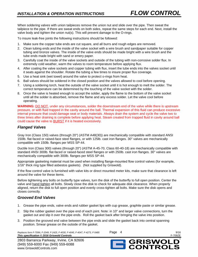
When soldering valves with union tailpieces remove the union nut and slide over the pipe. Then sweat the tailpiece to the pipe. If there are sweat ends on both sides, repeat the same steps for each end. Next, install the valve body and tighten the union nut(s). This will prevent damage to the O-rings.
To insure leak-free joints the following instructions should be followed:
1. Make sure the copper tube ends are cut square, and all burrs and rough edges are removed. 2. Clean tubing ends and the inside of the valve socket with a wire brush and sandpaper suitable for copper
tubing and bronze valves. The inside of the valve ends should be made bright with a wire brush and the tube ends made bright with sand or emery paper.
3. Carefully coat the inside of the valve sockets and outside of the tubing with non-corrosive solder flux. In extremely cold weather, warm the valves to room temperature before applying flux.
4. After coating the valve sockets and copper tubing with flux, insert the tube ends into the valves socket until it seats against the shoulder. Rotate the tubing a few times to insure proper flux coverage.
5. Use a heat sink (wet towel) around the valve to protect o-rings from heat. 6. Ball valves should be soldered in the closed position and the valves allowed to cool before opening. 7. Using a soldering torch, heat the outside of the valve socket until it is hot enough to melt the solder. The
correct temperature can be determined by the touching of the valve socket with the solder. 8. Once the valve is heated enough to accept the solder, apply the flame to the bottom of the valve socket
until all the solder is absorbed, remove the flame and any excess solder. Let the valve cool before operating.
WARNING: DO NOT, under any circumstances, solder the downstream end of the valve while there is upstream pressure, or with fluid trapped in the cavity around the ball. Thermal expansion of this fluid can produce excessive internal pressure that could damage seat or body materials. Always drain the system and cycle the valve two to three times after draining is complete before applying heat. Steam created from trapped fluid in cavity around ball could cause the valve to BURST if it is heated excessively.
Flanged Valves
Gray Iron (Class 150) valves (through 20") (ASTM A48(30)) are mechanically compatible with standard ANSI 150lb. flat-faced or raised-face steel flanges, or with 125lb. cast iron flanges. 30" valves are mechanically compatible with 150lb. flanges per MSS SP-44.
Ductile Iron (Class 300) valves (through 20") (ASTM A-45-70, Class 60-40-18) are mechanically compatible with standard ANSI 300lb. flat-faced or raised-faced steel flanges or with 250lb. cast iron flanges. 30" valves are mechanically compatible with 300lb. flanges per MSS SP-44.
Appropriate gasketing material must be used when installing flange-mounted flow control valves (for example, 1/16" thick ring type filled asbestos gaskets). (Not supplied by Griswold).
If the flow control valve is furnished with valve kits or direct mounted meter kits, make sure that clearance is left around the valve for these items.
Before tightening any bolts on butterfly type valves, turn the disk of the butterfly to full open position. Center the valve and hand tighten all bolts. Slowly close the disk to check for adequate disk clearance. When properly aligned, return the disk to full open position and evenly cross-tighten all bolts. Make sure the disk opens and closes correctly.
Grooved End Valves
1. Grease the pipe ends, valve ends and rubber gasket lips with cup grease, graphite paste or similar grease.
2. Slip the rubber gasket over the pipe end of each joint. Note: in 10" and larger valve connections, turn the gasket out and slip it over the pipe ends. Roll the gasket back after bringing the valve into position.
3. Position the grooved end valve between the pipe ends and slide the gasket back into central spanning position. Smear grease on the outside of the gasket.
INSTALLATION & OPERATION INSTRUCTIONS FLOW CONTROL
Replaces form F-709N, F-2049, F-2425, F-4030, F-4045, F-4047, F-4273, F-5485 Page 9/16 This specification © 2016 Griswold Controls F-709ZE
2803 Barranca Parkway, Irvine, CA 92606 (949) 559-6000 Fax (949) 559-6088 www.GriswoldControls.com
5
4. Put housing clamps over gasket – insert bolts and nuts.
5. Tighten nuts evenly, using socket or other wrench. (Note: best speed of assembly is obtained with brace or T-Handle wrenches.) Tighten so that housing clamps come together evenly. This avoids gasket pinching. When housing clamps meet metal to metal, further tightening of bolts is not necessary or desirable.
6. Pre-assemble large diameter multi-segment housing clamps loosely, and install them as half-housings. Take up evenly from top to bottom on alternate bolts.
Weld End Valves
1. Clean the end of the valve and pipe where the weld will be made. Make up the assembly butting the connections together.
2. Tack weld the assembly together and observe fit. WARNING: If valve contains a butterfly valve do not finish welding the flanges to the pipe with the butterfly valve bolted between the flanges. This will result in serious heat damage to the rubber gaskets and valve seat.
3. Remove the bolting and flange from between the flanges. Finish welding the piping together and allow flanges to cool completely before reinstalling and bolting the butterfly valve in its original position.
Actuator Operated Valves
Griswold Controls actuators are factory aligned with valve position and end stop set when part of a pre-assembled valve and will rotate 90. Field mounting requires the installer following good industry practice, to align actuator settings with valve positions and set the end stops before operation.
Non Failsafe models: Clockwise/Counterclockwise rotation can be changed via a field accessible switch on the actuator housing. See actuator cover for direction.
Failsafe models: Turn actuator upside down to change rotation.
1. To prevent moisture from collecting in the actuator motor casing, install the actuated ball valve so that the actuator is above the valve. Never drill into the motor casing!
2. ½” – 3”: Ball rotation is clockwise for “OFF” and counterclockwise for “ON”. 4”-6”: Ball rotation is clockwise for “ON” and counterclockwise for “OFF”.
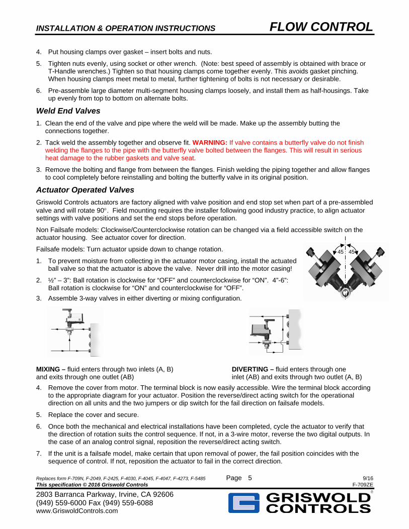
3. Assemble 3-way valves in either diverting or mixing configuration.
MIXING – fluid enters through two inlets (A, B) DIVERTING – fluid enters through one and exits through one outlet (AB) inlet (AB) and exits through two outlet (A, B)
4. Remove the cover from motor. The terminal block is now easily accessible. Wire the terminal block according to the appropriate diagram for your actuator. Position the reverse/direct acting switch for the operational direction on all units and the two jumpers or dip switch for the fail direction on failsafe models.
5. Replace the cover and secure.
6. Once both the mechanical and electrical installations have been completed, cycle the actuator to verify that the direction of rotation suits the control sequence. If not, in a 3-wire motor, reverse the two digital outputs. In the case of an analog control signal, reposition the reverse/direct acting switch.
7. If the unit is a failsafe model, make certain that upon removal of power, the fail position coincides with the sequence of control. If not, reposition the actuator to fail in the correct direction.
45 45
INSTALLATION & OPERATION INSTRUCTIONS FLOW CONTROL
Replaces form F-709N, F-2049, F-2425, F-4030, F-4045, F-4047, F-4273, F-5485 Page 9/16 This specification © 2016 Griswold Controls F-709ZE
2803 Barranca Parkway, Irvine, CA 92606 (949) 559-6000 Fax (949) 559-6088 www.GriswoldControls.com
6
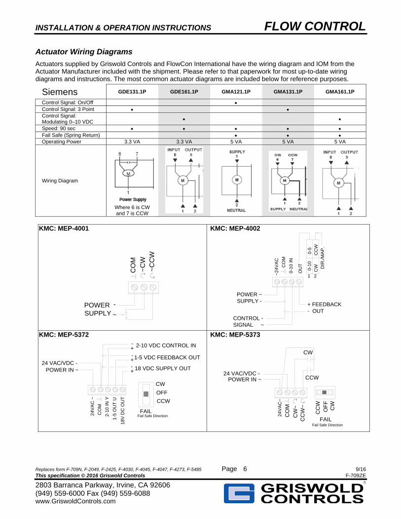
Actuator Wiring Diagrams
Actuators supplied by Griswold Controls and FlowCon International have the wiring diagram and IOM from the Actuator Manufacturer included with the shipment. Please refer to that paperwork for most up-to-date wiring diagrams and instructions. The most common actuator diagrams are included below for reference purposes.
Siemens GDE131.1P GDE161.1P GMA121.1P GMA131.1P GMA161.1P
Control Signal: On/Off Control Signal: 3 Point Control Signal: Modulating 0–10 VDC
Speed: 90 sec Fail Safe (Spring Return) Operating Power 3.3 VA 3.3 VA 5 VA 5 VA 5 VA
Wiring Diagram
Where 6 is CW and 7 is CCW
KMC: MEP-4001
POWERSUPPLY
CO
M
~C
W~
CC
W
-
~
KMC: MEP-4002
POWER ~SUPPLY -
CONTROL - SIGNAL ~
+ FEEDBACK- OUT
~24
VA
C
0-10
IN
OU
TCO
M
0-1
00-
5 C
WC
CW
DIR
./M
AP
.
1 2
KMC: MEP-5372
24V
AC
~
2-10
IN
Y
CO
M
2-10 VDC CONTROL IN
1-5
OU
T U
18V
DC
OU
T
1-5 VDC FEEDBACK OUT
18 VDC SUPPLY OUT
+ -
POWER IN ~24 VAC/VDC -
CCW
CW
OFF
FAILFail Safe Direction
+ -
+ -
KMC: MEP-5373
CO
M
CW
~C
CW
~
24V
AC
~
CW
CCW
CC
W
CW
OF
F
POWER IN ~24 VAC/VDC -
FAILFail Safe Direction
INSTALLATION & OPERATION INSTRUCTIONS FLOW CONTROL
Replaces form F-709N, F-2049, F-2425, F-4030, F-4045, F-4047, F-4273, F-5485 Page 9/16 This specification © 2016 Griswold Controls F-709ZE
2803 Barranca Parkway, Irvine, CA 92606 (949) 559-6000 Fax (949) 559-6088 www.GriswoldControls.com
7
Hoses
WARNING: Ignoring these installation guidelines can lead to catastrophic hose failure.
Hoses are intended for ease of equipment connection NOT seismic isolation. Proper hose installation is essential for satisfactory performance. If hose length is excessive, the appearance of the installation will be unsatisfactory and unnecessary cost of equipment will be involved. If hose assemblies are too short to permit adequate flexing and changes in length due to expansion or contraction, hose service life will be reduced. Hoses can shrink in length by as much as 1 ¾” when under pressure, making proper length selection critical to service life.
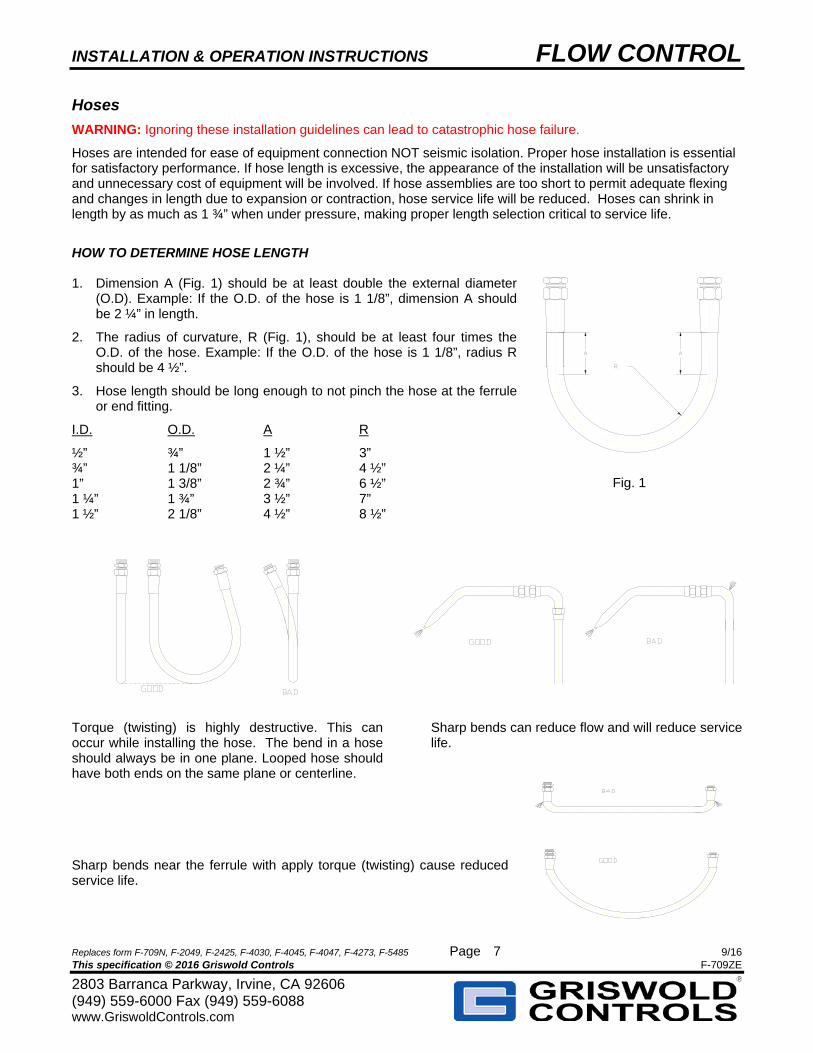
HOW TO DETERMINE HOSE LENGTH 1. Dimension A (Fig. 1) should be at least double the external diameter
(O.D). Example: If the O.D. of the hose is 1 1/8”, dimension A should be 2 ¼” in length.
2. The radius of curvature, R (Fig. 1), should be at least four times the O.D. of the hose. Example: If the O.D. of the hose is 1 1/8”, radius R should be 4 ½”.
3. Hose length should be long enough to not pinch the hose at the ferrule or end fitting.
I.D. O.D. A R
½” ¾” 1 ½” 3” ¾” 1 1/8” 2 ¼” 4 ½” 1” 1 3/8” 2 ¾” 6 ½” 1 ¼” 1 ¾” 3 ½” 7” 1 ½” 2 1/8” 4 ½” 8 ½”
Torque (twisting) is highly destructive. This can occur while installing the hose. The bend in a hose should always be in one plane. Looped hose should have both ends on the same plane or centerline.
Sharp bends can reduce flow and will reduce service life.
Sharp bends near the ferrule with apply torque (twisting) cause reduced service life.
Fig. 1
INSTALLATION & OPERATION INSTRUCTIONS FLOW CONTROL
Replaces form F-709N, F-2049, F-2425, F-4030, F-4045, F-4047, F-4273, F-5485 Page 61/9 This specification © 2016 Griswold Controls F-709ZE
2803 Barranca Parkway, Irvine, CA 92606(949) 559-6000 Fax (949) 559-6088 www.GriswoldControls.com
8
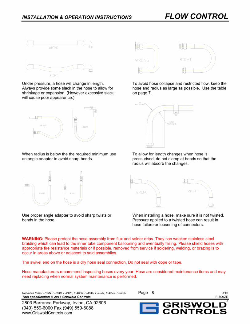
Under pressure, a hose will change in length. Always provide some slack in the hose to allow for shrinkage or expansion. (However excessive slack will cause poor appearance.)
To avoid hose collapse and restricted flow, keep the hose and radius as large as possible. Use the table on page 7.
When radius is below the the required minimum use an angle adapter to avoid sharp bends.
To allow for length changes when hose is pressurised, do not clamp at bends so that the radius will absorb the changes.
Use proper angle adapter to avoid sharp twists or bends in the hose.
When installing a hose, make sure it is not twisted. Pressure applied to a twisted hose can result in hose failure or loosening of connectors.
WARNING: Please protect the hose assembly from flux and solder drips. They can weaken stainless steel braiding which can lead to the inner tube component ballooning and eventually failing. Please shield hoses with appropriate fire resistance materials or if possible, removed from service if soldering, welding, or brazing is to occur in areas above or adjacent to said assemblies.
The swivel end on the hose is a dry hose seal connection. Do not seal with dope or tape.
Hose manufacturers recommend inspecting hoses every year. Hose are considered maintenance items and may need replacing when normal system maintenance is performed.
INSTALLATION & OPERATION INSTRUCTIONS FLOW CONTROL
Replaces form F-709N, F-2049, F-2425, F-4030, F-4045, F-4047, F-4273, F-5485 Page 9/16 This specification © 2016 Griswold Controls F-709ZE
2803 Barranca Parkway, Irvine, CA 92606 (949) 559-6000 Fax (949) 559-6088 www.GriswoldControls.com
9
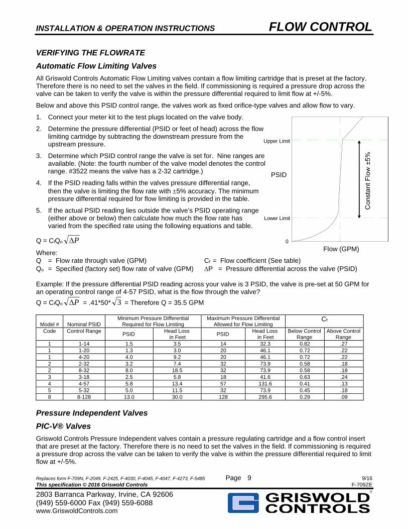
PSID
Flow (GPM) 0
Lower Limit
Upper Limit
VERIFYING THE FLOWRATE
Automatic Flow Limiting Valves
All Griswold Controls Automatic Flow Limiting valves contain a flow limiting cartridge that is preset at the factory. Therefore there is no need to set the valves in the field. If commissioning is required a pressure drop across the valve can be taken to verify the valve is within the pressure differential required to limit flow at +/-5%.
Below and above this PSID control range, the valves work as fixed orifice-type valves and allow flow to vary.
1. Connect your meter kit to the test plugs located on the valve body.
2. Determine the pressure differential (PSID or feet of head) across the flow limiting cartridge by subtracting the downstream pressure from the upstream pressure.
3. Determine which PSID control range the valve is set for. Nine ranges are available. (Note: the fourth number of the valve model denotes the control range. #3522 means the valve has a 2-32 cartridge.)
4. If the PSID reading falls within the valves pressure differential range, then the valve is limiting the flow rate with 5% accuracy. The minimum pressure differential required for flow limiting is provided in the table.
5. If the actual PSID reading lies outside the valve’s PSID operating range (either above or below) then calculate how much the flow rate has varied from the specified rate using the following equations and table.
Q = CfQo P
Where: Q = Flow rate through valve (GPM) Cf = Flow coefficient (See table) Qo = Specified (factory set) flow rate of valve (GPM) P = Pressure differential across the valve (PSID) Example: If the pressure differential PSID reading across your valve is 3 PSID, the valve is pre-set at 50 GPM for an operating control range of 4-57 PSID, what is the flow through the valve?
Q = CfQo P = .41*50* 3 = Therefore Q = 35.5 GPM
Model #
Nominal PSID
Minimum Pressure Differential Required for Flow Limiting
Maximum Pressure Differential Allowed for Flow Limiting
Cf
Code Control Range PSID
Head Loss in Feet
PSID Head Loss
in Feet Below Control
Range Above Control
Range 1 1-14 1.5 3.5 14 32.3 0.82 .27 1 1-20 1.3 3.0 20 46.1 0.72 .22 1 4-20 4.0 9.2 20 46.1 0.72 .22 2 2-32 3.2 7.4 32 73.9 0.58 .18 2 8-32 8.0 18.5 32 73.9 0.58 .18 3 3-18 2.5 5.8 18 41.6 0.63 .24 4 4-57 5.8 13.4 57 131.6 0.41 .13 5 5-32 5.0 11.5 32 73.9 0.45 .18 8 8-128 13.0 30.0 128 295.6 0.29 .09
Pressure Independent Valves
PIC-V® Valves
Griswold Controls Pressure Independent valves contain a pressure regulating cartridge and a flow control insert that are preset at the factory. Therefore there is no need to set the valves in the field. If commissioning is required a pressure drop across the valve can be taken to verify the valve is within the pressure differential required to limit flow at +/-5%.
INSTALLATION & OPERATION INSTRUCTIONS FLOW CONTROL
Replaces form F-709N, F-2049, F-2425, F-4030, F-4045, F-4047, F-4273, F-5485 Page 9/16 This specification © 2016 Griswold Controls F-709ZE
2803 Barranca Parkway, Irvine, CA 92606 (949) 559-6000 Fax (949) 559-6088 www.GriswoldControls.com
10
PIM-V™ Valves
After installation and venting air turn the ball valve to desired position and turn the needle valve on the cap one full turn from closed position for regulation to begin. If commissioning is required a pressure drop across the valve can be taken to verify the valve is within the pressure differential required to limit flow at +/-5%.
PIM™ Valves
After installation of high (upstream) pressure tubing and pressurizing system, use a standard ½” Allen Key to turn the adjustment on the cap counterclockwise (decrease the PSID over the adjusted branch) or clockwise (increase the PSID over the adjusted branch.) To increase to maximum PSID turn the knob about 7 turns. Maximum PSID is 25. Minimum PSID is 4. WARNING: Adjustment should be done slowly, approximately one turn every 10 sec.
To verify the PSID use a meter kit to measure the upstream versus downstream pressures. The valve takes about 30-60 seconds to stabilize PSID after adjustment.
Manual Balance Valves (QuickSet® and QuickDisc™)
1. Valve(s) are ordered by line size. Flow rates are set by adjusting the ball valve, disc or butterfly valve until the differential pressure reading across the valve corresponds to the required flow (GPM). QuickSet: Use the flow graphs to set the position. (1/2"–2": Form #F-4040; 2-1/2"–18": Form #F-4439) QuickDisc: Use the flow table to set position. (Form F-5547)
2. Once the Valve(s) has been installed and the system has been filled and purged, each valve loop must be set to the correct flow setting. Multiple passes are generally required to get the system in balance as the adjustment of each new valve affects the pressure drop (and flow) through the previously adjusted valves.
3. A meter kit can be purchased to take the differential pressure readings. The kit consists of either a 0-100" or 0-300" water column test gauge with the appropriate control valves, hoses and fittings.
4. When all valves in the system have been correctly adjusted, the locking Memory Stop should be set to prevent changes in flow rate. On the QuickSet, to set the memory stop, loosen the screw on the handle and re-tighten the screw after setting handle to correct position. On the QuickDisc, rotate the lever handle down so that the lever handle touches the housing. (It may already be rotated down.) Using your hand rotate the memory stop ring so that the chamfered edge stops rotating at the lever. Don’t tighten ring with a tool as it may damage ring. The ring should be snug. Now the lever can be rotated in between closed and set position.
5. The memory stop will allow the valve to be used for isolation and then be reopened to the preset flow position.
Manual Balance Valve Meter Kit
The meter kit is a portable device designed for field measuring or monitoring of differential pressure across a flow element, such as a venturi, for balancing heating and cooling systems.
The 6” test gauge is mounted in a lightweight, extremely rugged plastic case with the appropriate control valves, fittings and 10’ hoses. The 6” test gauge is scaled for 0-100” or 0-300” H2O.
Connect and use the meter kit with the QuickSet or QuickDisc manual balance valves as follows:
1. Open the balance control valve at the bottom of the meter kit face.
2. Connect the high pressure hose to the upstream port on the QuickSet or QuickDisc. (On QuickSet that is the port pointing in the same direction as the handle when the valve is closed.) Connect the low pressure hose to the other port. The gauge should show a pressure reading.
3. Open and close the Bleed valves to release any air trapped in the hoses and gauge assembly.
4. Close the balance control valve on meter kit face. The meter is ready to take differential pressure readings.
Setting the QuickSet or QuickDisc
1. Select the correct pressure drop for the desired flow rate for the valve using the flow table. With the system pressure on, and the valve handle in full open position, take a reading of the flow across the venturi (valve).
INSTALLATION & OPERATION INSTRUCTIONS FLOW CONTROL
Replaces form F-709N, F-2049, F-2425, F-4030, F-4045, F-4047, F-4273, F-5485 Page 9/16 This specification © 2016 Griswold Controls F-709ZE
2803 Barranca Parkway, Irvine, CA 92606 (949) 559-6000 Fax (949) 559-6088 www.GriswoldControls.com
11
2. If a reading of zero is present, there may be other valves in the system loop that are closed and will need to be opened to allow flow in this portion of the system. If a reading other than zero is present, use the valve handle to adjust the flow to the correct pressure reading for the unit. Closing the handle will decrease to flow.
3. Repeat this adjustment for all valves in the system, taking three passes to insure accuracy.
4. Use the adjustable Memory Stop to set the opening limit of the valve to the corrected setting. The Memory stop will allow the valve to be used (closed) as an isolation valve and then reopened to the pre-set flow rate without the need for reconnection of the meter kit.
CARTRIDGE REMOVAL
Isolator R, Isolator Y, Automizer®, K Valve, PIC-V®, Uni-Flange
Cartridge removal in these valves can be accomplished without removing the valve from the line. Isolate the system, relieve pressure and drain water. Carefully remove the cap and pull the cartridge(s) out with your fingers. When refitting a cartridge, make sure the O-ring or gasket on the cartridge and O-ring on the cap are in place.
Threaded Mini, Combo Valve
Cartridge removal in these valves can be accomplished after the valve housing is removed from the line.
Tools Required
No tools are required for 1/2" & 3/4" FCV's. Use 1/2" SCH 40 PVC x 5" long with bolt head to remove the cartridge from 1", 1-1/4", and 1-1/2" FCV models.
Use 1" SCH 40 PVCx5-1/2" long with aluminum head to insert the 1-1/4" cartridge in the 1", 1-1/4" & 1-1/2"FCV's.
Removing Cartridge
1. Isolate the system, relieve pressure and drain water. Remove the FCV housing from the system.
2. With a screwdriver, remove the clip ring from inside the housing (around cartridge at the base of cup, up-stream side).
3. For 1/2" & 3/4" FCV only - Cartridge is slip fit with an O-ring seal. Do not use pliers on cup (damage may result). For 1" to 1-1/2" housing, insert the tool completely inside the cartridge and tap it out with a hammer. The tool should rest on the inside of the cup with the orifice openings to prevent damage to the spring.
Inserting the Cartridge
1. On 1/2" & 3/4", reverse procedure used in removal. For 1" to 1-1/2" housing, place the cartridge in the FCV housing and then place the housing on a solid surface. Use hammer to tap down the cartridge into the housing seat (approximately 3/4" travel).
2. Reinstall, or replace the clip ring in the housing grooves and reassemble the end pieces and O-rings.
Wafer, Grooved End, Flange End
Cartridge removal in these valves can be accomplished after the valve housing is removed from the line.
Removing Cartridge
1. Isolate the system, relieve pressure and drain water. Remove the FCV housing from the system.
2. With a screwdriver, remove the screws and clips that hold the cartridge(s) in place.
3. Remove the cartridge(s) from the housing.
Inserting the Cartridge
1. Reverse procedure used in removal.
INSTALLATION & OPERATION INSTRUCTIONS FLOW CONTROL
Replaces form F-709N, F-2049, F-2425, F-4030, F-4045, F-4047, F-4273, F-5485 Page 9/16 This specification © 2016 Griswold Controls F-709ZE
2803 Barranca Parkway, Irvine, CA 92606 (949) 559-6000 Fax (949) 559-6088 www.GriswoldControls.com
12
BALL VALVE STEM REMOVAL
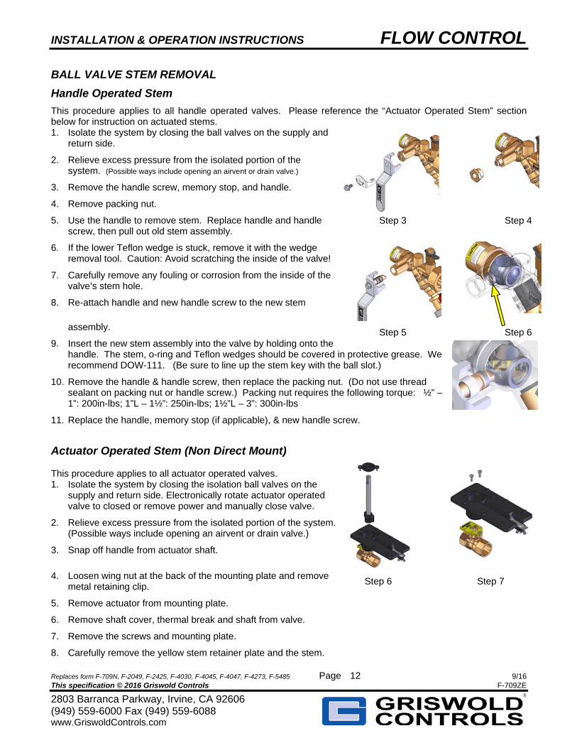
Handle Operated Stem
This procedure applies to all handle operated valves. Please reference the “Actuator Operated Stem” section below for instruction on actuated stems. 1. Isolate the system by closing the ball valves on the supply and
return side.
2. Relieve excess pressure from the isolated portion of the system. (Possible ways include opening an airvent or drain valve.)
3. Remove the handle screw, memory stop, and handle.
4. Remove packing nut.
5. Use the handle to remove stem. Replace handle and handle screw, then pull out old stem assembly.
6. If the lower Teflon wedge is stuck, remove it with the wedge removal tool. Caution: Avoid scratching the inside of the valve!
7. Carefully remove any fouling or corrosion from the inside of the valve’s stem hole.
8. Re-attach handle and new handle screw to the new stem
assembly.
9. Insert the new stem assembly into the valve by holding onto the handle. The stem, o-ring and Teflon wedges should be covered in protective grease. We recommend DOW-111. (Be sure to line up the stem key with the ball slot.)
10. Remove the handle & handle screw, then replace the packing nut. (Do not use thread sealant on packing nut or handle screw.) Packing nut requires the following torque: ½” – 1”: 200in-lbs; 1”L – 1½”: 250in-lbs; 1½”L – 3”: 300in-lbs
11. Replace the handle, memory stop (if applicable), & new handle screw.
Actuator Operated Stem (Non Direct Mount) This procedure applies to all actuator operated valves. 1. Isolate the system by closing the isolation ball valves on the
supply and return side. Electronically rotate actuator operated valve to closed or remove power and manually close valve.
2. Relieve excess pressure from the isolated portion of the system. (Possible ways include opening an airvent or drain valve.)
3. Snap off handle from actuator shaft.
4. Loosen wing nut at the back of the mounting plate and remove metal retaining clip.
5. Remove actuator from mounting plate.
6. Remove shaft cover, thermal break and shaft from valve.
7. Remove the screws and mounting plate.
8. Carefully remove the yellow stem retainer plate and the stem.
Step 3 Step 4
Step 5 Step 6
Step 6 Step 7
INSTALLATION & OPERATION INSTRUCTIONS FLOW CONTROL
Replaces form F-709N, F-2049, F-2425, F-4030, F-4045, F-4047, F-4273, F-5485 Page 9/16 This specification © 2016 Griswold Controls F-709ZE
2803 Barranca Parkway, Irvine, CA 92606 (949) 559-6000 Fax (949) 559-6088 www.GriswoldControls.com
13
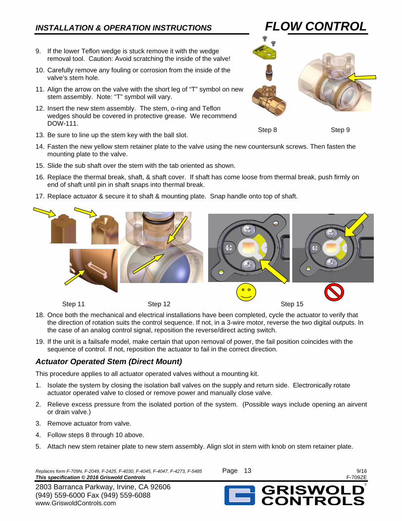
9. If the lower Teflon wedge is stuck remove it with the wedge removal tool. Caution: Avoid scratching the inside of the valve!
10. Carefully remove any fouling or corrosion from the inside of the valve’s stem hole.
11. Align the arrow on the valve with the short leg of “T” symbol on new stem assembly. Note: “T” symbol will vary.
12. Insert the new stem assembly. The stem, o-ring and Teflon wedges should be covered in protective grease. We recommend DOW-111.
13. Be sure to line up the stem key with the ball slot.
14. Fasten the new yellow stem retainer plate to the valve using the new countersunk screws. Then fasten the mounting plate to the valve.
15. Slide the sub shaft over the stem with the tab oriented as shown.
16. Replace the thermal break, shaft, & shaft cover. If shaft has come loose from thermal break, push firmly on end of shaft until pin in shaft snaps into thermal break.
17. Replace actuator & secure it to shaft & mounting plate. Snap handle onto top of shaft.
18. Once both the mechanical and electrical installations have been completed, cycle the actuator to verify that the direction of rotation suits the control sequence. If not, in a 3-wire motor, reverse the two digital outputs. In the case of an analog control signal, reposition the reverse/direct acting switch.
19. If the unit is a failsafe model, make certain that upon removal of power, the fail position coincides with the sequence of control. If not, reposition the actuator to fail in the correct direction.
Actuator Operated Stem (Direct Mount)
This procedure applies to all actuator operated valves without a mounting kit.
1. Isolate the system by closing the isolation ball valves on the supply and return side. Electronically rotate actuator operated valve to closed or remove power and manually close valve.
2. Relieve excess pressure from the isolated portion of the system. (Possible ways include opening an airvent or drain valve.)
3. Remove actuator from valve.
4. Follow steps 8 through 10 above.
5. Attach new stem retainer plate to new stem assembly. Align slot in stem with knob on stem retainer plate.
Step 8 Step 9
Step 11 Step 12 Step 15
INSTALLATION & OPERATION INSTRUCTIONS FLOW CONTROL
Replaces form F-709N, F-2049, F-2425, F-4030, F-4045, F-4047, F-4273, F-5485 Page 9/16 This specification © 2016 Griswold Controls F-709ZE
2803 Barranca Parkway, Irvine, CA 92606 (949) 559-6000 Fax (949) 559-6088 www.GriswoldControls.com
14
6. Fasten the new stem assembly & new retaining plate to valve using new countersunk screws. Be sure to line up the stem key with the ball slot.
7. Replace actuator & secure it to stem.
8. Once both the mechanical and electrical installations have been completed, cycle the actuator to verify that the direction of rotation suits the control sequence. If not, in a 3-wire motor, reverse the two digital outputs. In the case of an analog control signal, reposition the reverse/direct acting switch.
9. If the unit is a failsafe model, make certain that upon removal of power, the fail position coincides with the sequence of control. If not, reposition the actuator to fail in the correct direction.
REPLACING THE SEALS AND O–RINGS
In the event that the valve begins to leak through even when in a fully closed position, the ball seals and seal o-rings can be replaced.
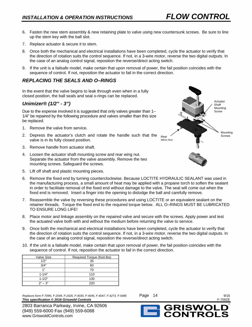
Unimizer® (1/2” - 3”)
Due to the expense involved it is suggested that only valves greater than 1–1/4" be repaired by the following procedure and valves smaller than this size be replaced.
1. Remove the valve from service.
2. Depress the actuator’s clutch and rotate the handle such that the valve is in its fully closed position.
3. Remove handle from actuator shaft.
4. Loosen the actuator shaft mounting screw and rear wing nut. Separate the actuator from the valve assembly. Remove the two mounting screws. Safeguard the screws.
5. Lift off shaft and plastic mounting pieces.
6. Remove the fixed end by turning counterclockwise. Because LOCTITE HYDRAULIC SEALANT was used in the manufacturing process, a small amount of heat may be applied with a propane torch to soften the sealant in order to facilitate removal of the fixed end without damage to the valve. The seal will come out when the fixed end is removed. Insert a finger into the opening to dislodge the ball and carefully remove.
7. Reassemble the valve by reversing these procedures and using LOCTITE or an equivalent sealant on the retainer threads. Torque the fixed end to the required torque below. ALL O–RINGS MUST BE LUBRICATED TO ENSURE LONG LIFE!
8. Place motor and linkage assembly on the repaired valve and secure with the screws. Apply power and test the actuated valve both with and without the medium before returning the valve to service.
9. Once both the mechanical and electrical installations have been completed, cycle the actuator to verify that the direction of rotation suits the control sequence. If not, in a 3-wire motor, reverse the two digital outputs. In the case of an analog control signal, reposition the reverse/direct acting switch.
10. If the unit is a failsafe model, make certain that upon removal of power, the fail position coincides with the sequence of control. If not, reposition the actuator to fail in the correct direction.
Valve Size Required Torque (foot-lbs)1/2" 35 3/4" 60 1" 70
1-1/4" 110 1-1/2" 130 2" – 3” 220
Actuator Shaft Mounting Screw
Mounting Screws Rear
Wing Nut
INSTALLATION & OPERATION INSTRUCTIONS FLOW CONTROL
Replaces form F-709N, F-2049, F-2425, F-4030, F-4045, F-4047, F-4273, F-5485 Page 9/16 This specification © 2016 Griswold Controls F-709ZE
2803 Barranca Parkway, Irvine, CA 92606 (949) 559-6000 Fax (949) 559-6088 www.GriswoldControls.com
15
Automizer/PIC–V
1. Follow Unimizer steps 1 through 5.
2. Remove the union end by turning counterclockwise. Replace union O–ring if necessary.
3. Remove internal retainer. The seal and ball will come out when the retainer is removed.
4. Remove and then discard the old end seals and O–ring.
5. Reassemble the valve by reversing these procedures and using LOCTITE or an equivalent sealant on the retainer threads. ALL O–RINGS MUST BE LUBRICATED TO ENSURE LONG LIFE!
6. Place motor and linkage assembly on the repaired valve and secure with the screws. Apply power and test the actuated valve both with and without the medium before returning the valve to service.
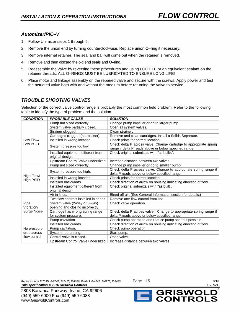
TROUBLE SHOOTING VALVES
Selection of the correct valve control range is probably the most common field problem. Refer to the following table to identify the type of problem and the solution.
CONDITION PROBABLE CAUSE SOLUTION
Low Flow/ Low PSID
Pump not sized correctly. Change pump impeller or go to larger pump. System valve partially closed. Open all system valves. Strainer clogged. Clean strainer. Cartridges clogged (no strainer). Remove and clean cartridges. Install a Solids Separator. Installed in wrong location. Check prints for correct location.
System pressure too low. Check delta P across valve. Change cartridge to appropriate spring range if delta P reads above or below specified range.
Installed equipment different from original design.
Check original submittals with "as builts".
Upstream Control Valve undersized Increase distance between two valves
High Flow/ High PSID
Pump not sized correctly. Change pump impeller or go to smaller pump.
System pressure too high. Check delta P across valve. Change to appropriate spring range if delta P reads above or below specified range.
Installed in wrong location. Check prints for correct location. Installed backwards. Check direction of arrow on housing indicating direction of flow. Installed equipment different from original design.
Check original submittals with "as built".
Pipe Vibration/ Surge Noise
Air in lines. Bleed off air. (See General Information section for details.) Two flow controls installed in series. Remove one flow control from line. System valve (2-way or 3-way) opening and closing incorrectly.
Check valve operation.
Cartridge has wrong spring range for system pressure.
Check delta P across valve. Change to appropriate spring range if delta P reads above or below specified range.
Pump cavitation. Check pump operation and reduce pump speed if possible.
No pressure drop across flow control
Installed backwards. Check direction of arrow on housing indicating direction of flow. Pump cavitation. Check pump operation. System not running. Start pump. Control valve is closed. Open valve. Upstream Control Valve undersized Increase distance between two valves
INSTALLATION & OPERATION INSTRUCTIONS FLOW CONTROL
Replaces form F-709N, F-2049, F-2425, F-4030, F-4045, F-4047, F-4273, F-5485 Page 9/16 This specification © 2016 Griswold Controls F-709ZE
2803 Barranca Parkway, Irvine, CA 92606 (949) 559-6000 Fax (949) 559-6088 www.GriswoldControls.com
16
WARRANTY
Griswold Controls agrees to repair or replace, at Griswold Controls’ option, any Product found to be defective in workmanship or material during the warranty period. Griswold Controls Limited Warranty does not include labor or additional materials to repair or replace defective Product. Claims under this warranty will only be honored if written notice is given to Griswold Controls immediately upon discovery of the defect and within the specified warranty period from the date of shipment. A Product is not defective unless it fails to perform according to Griswold Controls’ written specifications, but in the event Griswold Controls has not drafted or adopted written specifications for a particular Product, a Product will be defective if it fails to perform as would be expected of the same or similar Product in the industry. Customer shall pay freight charges for return. There is no warranty for any Product that has been (i) subjected to misuse, neglect or accident, or (ii) altered or repaired in an improper manner. Refer to Griswold Product Installation, Operation, and Maintenance instructions for proper handling and use. Questions regarding Warranty Returns should be directed to your Customer Service Representative at (949) 559-6000 or via fax at (949) 559-6088.
Disclaimer of Liability THIS WARRANTY IS IN PLACE OF ALL OTHER WARRANTIES EXPRESS OR IMPLIED, INCLUDING IMPLIED WARRANTIES OF MERCHANTABILITY AND FITNESS FOR A PARTICULAR PURPOSE. THERE ARE NO WARRANTIES WHICH EXTEND BEYOND THE DESCRIPTION ON THE FACE HEREOF. THIS IS GRISWOLD’S ONLY LIABILITY TO ANYONE FOR ANY CLAIM IN CONNECTION WITH THE PRODUCTS. GRISWOLD SHALL NOT BE LIABLE FOR INCIDENTAL, SPECIAL OR CONSEQUENTIAL DAMAGES, LOSS OF PROFITS OR FOR DAMAGES IN AN AMOUNT EXCEEDING THE COST OF ANY DEFECTIVE PRODUCT(S) EVEN IF GRISWOLD HAS BEEN TOLD IN ADVANCE OF THE POSSIBILITY OF SUCH DAMAGES. IT IS AGREED THAT THE BUYER’S SOLE REMEDY AGAINST GRISWOLD IN CONNECTION WITH THE PRODUCT IS REPAIR OR REPLACEMENT OF THE DEFECTIVE PRODUCT OR REFUND OF THE PURCHASE PRICE OF THE PRODUCT. No agent, distributor or any other person is authorized to modify or extend the terms of this warranty in any manner whatsoever. Some states do not allow the exclusion or limitation of incidental or consequential damages, nevertheless, the foregoing paragraph should be construed to limit Griswold Controls’ liability to the fullest extent permitted under the laws of any particular jurisdiction, as applicable. This warranty gives you specific legal rights and you may also have other legal rights which vary from state to state. This warranty applies only to Products installed in North America. To obtain service under this Limited Warranty write to: Griswold Controls 2803 Barranca Parkway, Irvine, California 92606. Products may be returned for replacement or credit due to Product failure or defect during the standard warranty period. Griswold Controls Standard Product Warranty Periods are as follows: Product Category Warranty Period
Ball Valve/ Flow Control Valve Assembly (Excluding Cartridge) 1 Year CPP Components 1 Year Hoses 1 Year PIC-V, MVP, PIM Valves 1 Year Stainless Steel Cartridges 5 Year Actuators 1 Year Diaphragm Valves 1 Year