FLIP FLOPS - National Institute of Technology Calicut Electronics Lab_EXP...Set up and verify the...
4
EXP.NO.7 FLIP FLOPS AIM: 1. Set up and verify the operation of an SR latch using NAND gates. 2. Set up and verify the operation of clocked RS flip flops using NAND gates. 3. Set up and verify the operation of JK flip flops using NAND gates. 4. Set up and verify the operation of a Master Slave JK flip flop using NAND gates. 5. Convert the JK Flip Flop to D and T flip flop and verify the operation. Components Required: IC7400 Principle: A flip flop circuit can maintain binary state indefinitely (i.e., as long as power can be supplied to the circuit), until directed by an input signal to switch states. The major difference among various types of flip flops is in the number of inputs they possess. 1. SR Flip Flop: The basic SR flip flop circuit can be implemented by 2 input NAND gates. The flip flop has 2 inputs and 2 outputs. The circuit operates both inputs normally unless a change in state is required.By adding clock pulses to the input gate of an SR flip flop, clocked SR flip flop is obtained. The flip flop now changes its output state only when the clock pulse is given. Q QB CLK S R 2. D Flip Flop: It is a modification of SR flip flop. The D input goes directly to S and its compliment goes to R. If the D input is ON, the flip-flop goes to set state else it goes to reset sate. The
Transcript of FLIP FLOPS - National Institute of Technology Calicut Electronics Lab_EXP...Set up and verify the...
EXP.NO.7
FLIP FLOPS
AIM:
1. Set up and verify the operation of an SR latch using NAND gates.
2. Set up and verify the operation of clocked RS flip flops using NAND gates.
3. Set up and verify the operation of JK flip flops using NAND gates.
4. Set up and verify the operation of a Master Slave JK flip flop using NAND gates.
5. Convert the JK Flip Flop to D and T flip flop and verify the operation.
Components Required:
IC7400
Principle:
A flip flop circuit can maintain binary state indefinitely (i.e., as long as power can be
supplied to the circuit), until directed by an input signal to switch states. The major difference
among various types of flip flops is in the number of inputs they possess.
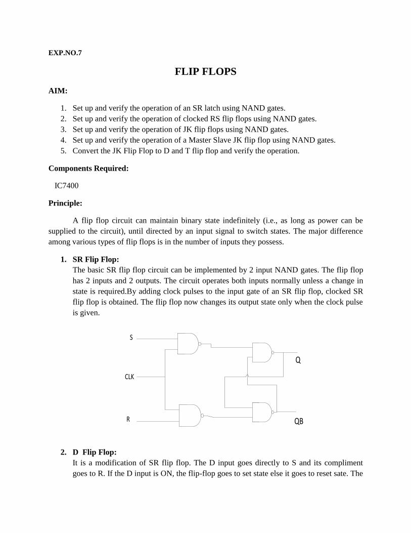
1. SR Flip Flop:
The basic SR flip flop circuit can be implemented by 2 input NAND gates. The flip flop
has 2 inputs and 2 outputs. The circuit operates both inputs normally unless a change in
state is required.By adding clock pulses to the input gate of an SR flip flop, clocked SR
flip flop is obtained. The flip flop now changes its output state only when the clock pulse
is given.
Q
QB
CLK
S
R
2. D Flip Flop:
It is a modification of SR flip flop. The D input goes directly to S and its compliment
goes to R. If the D input is ON, the flip-flop goes to set state else it goes to reset sate. The
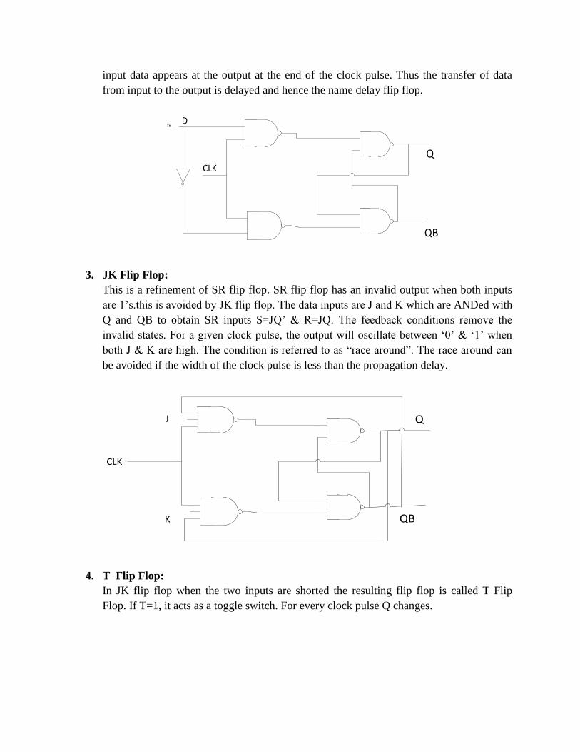
input data appears at the output at the end of the clock pulse. Thus the transfer of data
from input to the output is delayed and hence the name delay flip flop.
Q
QB
CLK
DA1
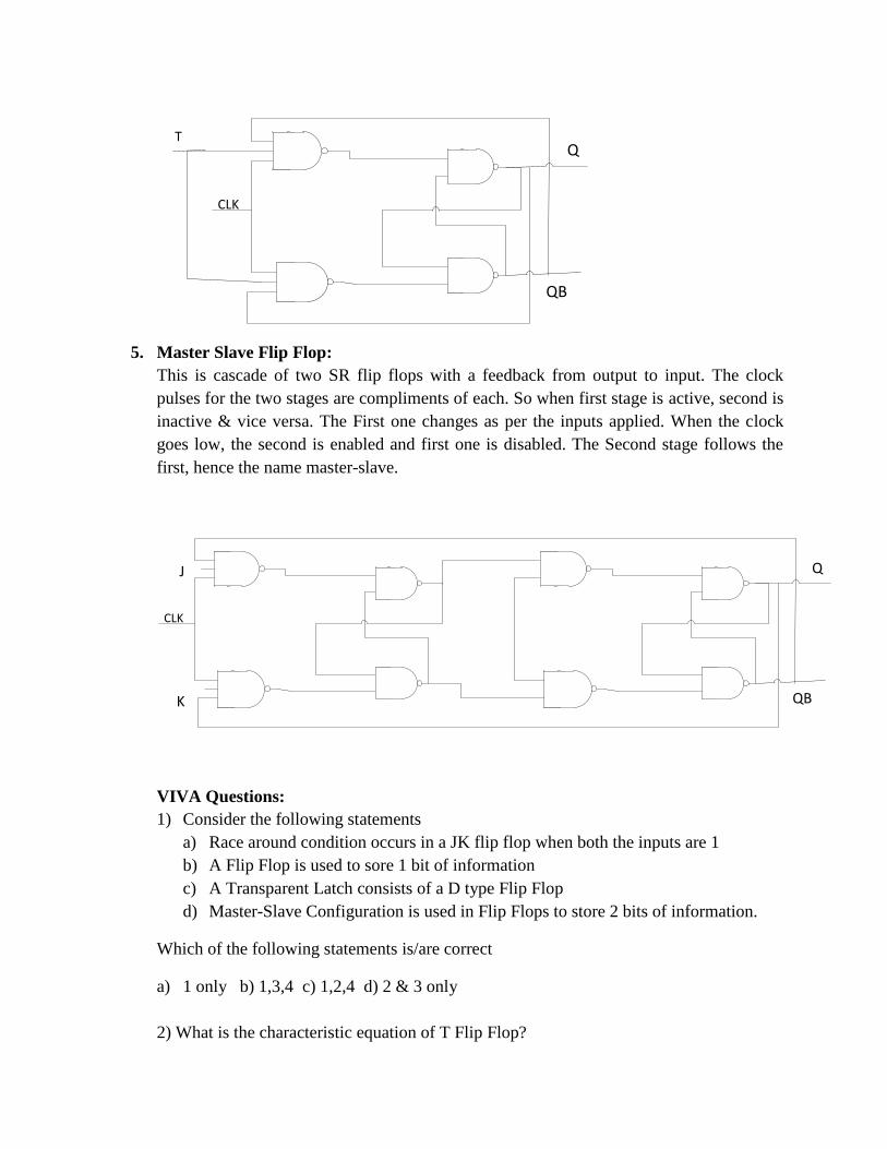
3. JK Flip Flop:
This is a refinement of SR flip flop. SR flip flop has an invalid output when both inputs
are 1’s.this is avoided by JK flip flop. The data inputs are J and K which are ANDed with
Q and QB to obtain SR inputs S=JQ’ & R=JQ. The feedback conditions remove the
invalid states. For a given clock pulse, the output will oscillate between ‘0’ & ‘1’ when
both J & K are high. The condition is referred to as “race around”. The race around can
be avoided if the width of the clock pulse is less than the propagation delay.
QB
CLK
J
K
Q
4. T Flip Flop:
In JK flip flop when the two inputs are shorted the resulting flip flop is called T Flip
Flop. If T=1, it acts as a toggle switch. For every clock pulse Q changes.
QB
CLK
TQ
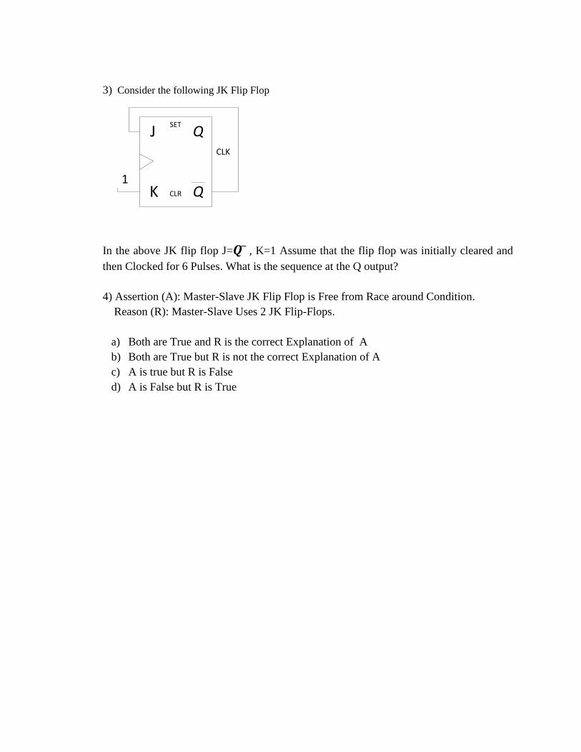
5. Master Slave Flip Flop:
This is cascade of two SR flip flops with a feedback from output to input. The clock
pulses for the two stages are compliments of each. So when first stage is active, second is
inactive & vice versa. The First one changes as per the inputs applied. When the clock
goes low, the second is enabled and first one is disabled. The Second stage follows the
first, hence the name master-slave.
QB
Q
K
CLK
J
VIVA Questions:
1) Consider the following statements
a) Race around condition occurs in a JK flip flop when both the inputs are 1
b) A Flip Flop is used to sore 1 bit of information
c) A Transparent Latch consists of a D type Flip Flop
d) Master-Slave Configuration is used in Flip Flops to store 2 bits of information.
Which of the following statements is/are correct
a) 1 only b) 1,3,4 c) 1,2,4 d) 2 & 3 only
2) What is the characteristic equation of T Flip Flop?
3) Consider the following JK Flip Flop
CLK
J
Q
Q
K
SET
CLR
1
In the above JK flip flop J= , K=1 Assume that the flip flop was initially cleared and
then Clocked for 6 Pulses. What is the sequence at the Q output?
4) Assertion (A): Master-Slave JK Flip Flop is Free from Race around Condition.
Reason (R): Master-Slave Uses 2 JK Flip-Flops.
a) Both are True and R is the correct Explanation of A
b) Both are True but R is not the correct Explanation of A
c) A is true but R is False
d) A is False but R is True