
Flight Trajectory Options to Mitigate the Impact of …...Flight Trajectory Options to Mitigate the...
25
Flight Trajectory Options to Mitigate the Impact of Unmanned Aircraft Systems (UAS) Contingency Trajectories – A Concept of Operations John Bernard Andrew R. Lacher September 2013 MP130508 MITRE PRODUCT Approved for Public Release. Distribution Unlimited. Case Number 13-3449. ©2013 The MITRE Corporation. All rights reserved. McLean, VA Center for Advanced Aviation System Development
Transcript of Flight Trajectory Options to Mitigate the Impact of …...Flight Trajectory Options to Mitigate the...

Flight Trajectory Options to Mitigate the Impact of Unmanned Aircraft Systems (UAS) Contingency Trajectories – A Concept of Operations
John Bernard Andrew R. Lacher September 2013
MP 1 3 05 0 8
MIT RE P R O DU CT
Approved for Public Release. Distribution Unlimited. Case Number 13-3449.
©2013 The MITRE Corporation.
All rights reserved.
McLean, VA
Center for Advanced Aviation System Development

iii
Executive Summary No NextGen Air Transportation System (NextGen) mid-term automation capability is currently
planned for storing and processing Unmanned Aircraft (UA) contingency trajectories.
Contingency trajectories are plans that would be executed in case of a loss of the command and
control (C2) link between the pilot’s control station and the UA, or some other unexpected event.
As a result, controllers have limited situational awareness and cannot depict an unmanned
aircraft’s flight trajectory on air traffic management displays during a contingency event.
This concept of operations proposes to re-purpose a Traffic Flow Management System (TFMS)
capability, scheduled for implementation in 2014, to facilitate coordination of UA contingency
trajectories between UA remote pilots and the air traffic management (ATM) system. A
Trajectory Option Set (TOS) message could be leveraged by the remote pilot to communicate
UA contingency trajectories. Optional to the concept, augmentations to existing TOS
specifications are described, which could quickly communicate to ATC a UA’s contingency
trajectory based on UA problem type (e.g., lost C2 link or other type of emergency situation).
Leveraging a mid-term capability such as TOS, (with essentially no modifications other than
Unmanned Aircraft System (UAS)-specific procedures) to handle UAS contingency trajectories
would help address a critical integration issue for UAS (lost C2 link), while providing greater
predictability, consistency, and situation awareness for controllers while enabling the use of
ATM decision support systems.

iv
Acknowledgments The authors would like to thank Nathan Paczan, David Simenauer, and Steve Fabela for their
input and guidance. The authors would like to acknowledge Mike Klinker and Dean Fulmer for
their review of and advice regarding this document. Additionally, the authors thank Angela
Signore and Sam Tungul for their support in editing and preparing the document for delivery.

v
Table of Contents
1 Introduction/Scope .................................................................................................................. 1
1.1 Background ....................................................................................................................... 1
1.2 Problem Statement ............................................................................................................ 2
1.3 Scope ................................................................................................................................. 3
1.4 Concept Relationship to UAS Integration into the NAS Concept of Operations ............. 3
2 Current Operations and Capabilities.................................................................................... 5
2.1 Description of Current Operation ...................................................................................... 5
2.2 Current Supporting Infrastructure ..................................................................................... 5
2.2.1 TFMS ......................................................................................................................... 5
2.2.1.1 Airborne Reroutes (ABRR) – Available in 2014 ............................................... 6
2.2.1.2 Trajectory Option Sets (TOS) – Available in 2014 ............................................ 7
2.2.2 ERAM – Currently Being Deployed, Deployment Completed in 2014 .................... 7
2.2.2.1 Conflict Probe – Currently Deployed in all 20 ARTCCs ................................... 7
2.2.2.2 Trial Planning – Currently Deployed in all 20 ARTCCs ................................... 7
2.2.2.3 ABRR – Available in 2014 ................................................................................ 7
2.2.2.4 System to Enable Flight Operator to File TOSs –Available in 2014 ................. 7
3 Flight Trajectory Options to Mitigate the Impact of Unmanned Aircraft Systems
Contingency Trajectories Concept of Operations ............................................................... 8
3.1 Assumptions and Constraints ............................................................................................ 8
3.2 Existing Automation Capabilities – Today’s Operating Environment ............................. 9
3.3 Potential Operations .......................................................................................................... 9
3.4 Benefits to be Realized .................................................................................................... 14
4 Summary of Impacts............................................................................................................. 15
4.1 Operational Impacts ........................................................................................................ 15
4.2 System Impacts ................................................................................................................ 15
5 References .............................................................................................................................. 17
Appendix A Glossary ............................................................................................................. A-1

vi
List of Figures Figure 1. UAS Elements in the NAS ............................................................................................. 1
Figure 2. Route Segments of a UA Flight Plan and Contingency Trajectory............................... 10
Figure 3. Example of UA Filed Flight Plan and Contingency Trajectories .................................. 11
Figure 4. TVST and TVET Updated to Reflect Actual Departure Time ...................................... 11
Figure 5. Applicable Contingency Trajectory for Current Time of 1938 ..................................... 12
Figure 6. Notional TFMS Route Amendment Dialog Box ........................................................... 12
Figure 7. Notional ERAM Controller GPD without Conflict Detected........................................ 13
Figure 8. Notional ERAM Controller GPD with Conflict Detected ............................................. 14
Figure 9. Contingency Operations Flow Chart – Example Use Case: Lost Link ......................... 14
List of Tables Table 1. Strategic Traffic Management Improvements .................................................................. 3
Table 2. Manned, Unmanned Aircraft Contingency Comparison . Error! Bookmark not defined.

1
1 Introduction/Scope
1.1 Background
Unlike with manned aircraft, the pilot in command (PIC) can lose connectivity (lost link) with an
unmanned aircraft (UA); however UA have the capability to continue controlled flight along a
pre-determined trajectory. This pre-determined trajectory may differ from the current Air Traffic
Control (ATC)-known Instrument Flight Rules (IFR) flight plan due to needs of the Unmanned
Aircraft System (UAS) to attempt to reestablish contact with the remote pilot or to satisfy other
UAS mission objectives, e.g., make a precautionary landing. The UA has one or more
programmed pre-determined trajectories to follow in the case of a lost command and control
(C2) link or other emergency situation. These are referred to as contingency trajectories. Figure
1 depicts the UAS linkages and the communication paths between the UAS crew and ATC.
Voice communications between the UAS crew and ATC are either via radio link through the UA
and then to ATC or via alternate communications to ATC (e.g., telephone).
Figure 1. UAS Elements in the NAS
Currently, capabilities are not planned for ATC and Traffic Flow Management (TFM) to store,
retrieve, and process UA contingency trajectories. UA contingency route information, when
available, may be stored, in written form in ATC facilities, in hard copy form and/or on the En
Route Information Display System (ERIDS) located in Air Route Traffic Control Centers
(ARTCCs). As a result, when a contingency trajectory is being flown that differs from the ATC
clearance, there is less predictability and a lack of situational awareness for radar air traffic
controllers (controllers). The contingency trajectory must be manually accessed and interpreted

2
by the controller. Therefore, there can be a significant delay in accessing this information – the
UAS may begin maneuvering before ATC has the information and has assessed the new
trajectory. There is only limited consistency among UA contingency trajectories, even with
similar UA flights, making it difficult for controllers to remember or become familiar with the
contingency trajectories.
The Traffic Flow Management System (TFMS) has evolved a capability for flight operators to
express not only a filed route of flight but a set of flight operator-provided trajectory options to
be used by TFM in the event the filed route is unavailable (e.g., due to weather or excess air
traffic volume). This concept of operations describes a capability that builds upon the Trajectory
Options Set (TOS) function already within the TFMS to enable ATC and TFM to store, retrieve,
and process UA contingency trajectories. The TFMS is described in Section 2.2.1. UAS flight
operators will have the capability to file and amend contingency trajectories with ATC in
advance of and during UAS operations.
1.2 Problem Statement
This section will first describe nominal aircraft and ATC operations, i.e., when aircraft are
following expected trajectories. ATC-cleared trajectories, more commonly referred to as ATC
clearances, are used by controllers and ATC automation to help predict future aircraft paths for
manual and automated problem identification and resolution. For example, if two aircraft, on
intersecting paths, are each assigned an altitude clearance that keeps the two aircraft safely
separated vertically, the controller working these two aircraft and the ATC automation will
predict both aircraft will comply with their altitude clearances and will predict they are safely
separated. Similarly, controllers and ATC automation will predict two aircraft at the same
altitude that are cleared via routings that keep the two aircraft safely separated horizontally, will
follow their ATC clearances and will remain safely separated.1
When UA encounter off-nominal situations (e.g., lost C2 link with the PIC, engine problems, or
other aircraft problems) they are pre-programmed to fly a contingency trajectory to help the UA
recover from the off-nominal situation and/or navigate to a pre-determined destination to land in
a safe manner.2 Contingency trajectories often differ from the UA’s ATC clearance. Therefore,
when a UA departs from its ATC clearance and follows a contingency trajectory, the controller
and the ATC automation lack the correct trajectory information needed to predict and solve
conflicts between the UA and other aircraft.
Replacing the last-assigned (and automation-stored) ATC clearance with the UA contingency
trajectory will correct the trajectory discrepancy; however, the current method of making this
correction is a manual and time-consuming process. To replace the current ATC clearance with
the UA contingency trajectory, controllers must first manually look up and interpret contingency
routes or they may interact verbally with the PIC via alternate communications paths (e.g., via
telephone service). In either case, controllers then need to manually enter the contingency
trajectory in ATC automation. Due to variances in the time and location, as well as the cause, of
1 Generally, FAA separation standards require controllers to separated aircraft (including UAs) on IFR flight plans by 1,000 feet
vertically or 5 statute miles laterally up to and including Flight Level 410 (FL410 or 41,000 feet pressure altitude) and 2,000
feet vertically or 5 miles above FL410 up to FL600. Additional separation rules apply to altitudes above FL600 and to other
situations. UAs and other aircraft discussed in the research proposal are those on IFR flight plans. 2 In some instances, the UA will navigate to a hold location where it has be pre-determined that if the C2 link is not
reestablished prior to fuel exhaustion, a crash will pose minimal risks. Currently, contingency procedures are contained in the
UA flight operator’s FAA-approved Certificate of Authorization (COA).

3
the contingency trajectory, there is only limited consistency among UA contingency trajectories,
even with similar UA flights. This makes it difficult for controllers to remember or become
familiar with the contingency trajectories. Furthermore, contingency routes are often in a
latitude/longitude or fixed radial distance format increasing the entry time and potential for input
error.
Most UAS have multiple contingency trajectory characteristics, which must be coordinated with
ATC, including:
Contingency trajectory definition, which may vary based on
o Problem Type (e.g., lost C2 link, engine problems, other aircraft problems)
o The segment of the UA’s filed route of flight upon which the UA is currently
located
Contingency Activation Time: Lag between start times of problems to the time
the UA activates its contingency
Manual Restore Time (MRT): If the time a UA has been on a contingency
trajectory exceeds a specified time duration (or MRT), then the UAS requires a
manual restore by the PIC to return to the previous trajectory
1.3 Scope
This paper documents a potential concept of operations which discusses how specific
contingency trajectories could be communicated between UAS flight operators and ATC. It is
beyond the scope of this paper to propose specifics associated with the contingency trajectory
path or other characteristics. It is also beyond the scope of this paper to explore systems UAS
operators would need in order to develop and submit contingency trajectories to the FAA via the
concept presented.
1.4 Concept Relationship to UAS Integration into the NAS Concept of Operations
This concept of operations supports the FAA’s Integration of Unmanned Aircraft Systems into
the National Airspace System Concept of Operations, (version 2.0) by proposing a mitigation for
controllers and ATC automation diminished awareness of UAS flight contingency trajectories.
The relationship between this Federal Aviation Administration (FAA) concept of operations and
the concept of operations described in this paper is depicted in Table 1, which is an excerpt from
the former concept of operations. [1]
Table 1. Strategic Traffic Management Improvements [1]
Past Practice Change with Integration Improvements
The COA/SAC-EC3 process
addressed contingency
operations as part of the
approval process, but they
UAS contingency procedures
are predetermined in most
cases, and are otherwise
described in the flight object
Contingency procedures are
known and available to
controllers in real time.
3 Special Airworthiness Certificate – Experimental Category

4
were not easily accessible to
ATC.
by flight segment.

5
2 Current Operations and Capabilities
2.1 Description of Current Operation
In today’s operation, controllers depend on each aircraft under their control to follow an assigned
route and altitude (and under certain ATC situations, airspeed). This gives each flight’s trajectory
predictable characteristics upon which a controller can depend to provide safe and efficient ATC
services.
One airborne aircraft problem that may lead to following a contingency trajectory situation is a
loss of the C2 link between the PIC and the UA, referred to as lost link. During a lost link event,
the PIC can no longer exert operational control over the path of the unmanned aircraft. While
ATC may be able to communicate with the PIC verbally, ATC will not be able to issue
clearances or instructions since the PIC can no longer control the aircraft and thus will not be
able to adhere to them. In this situation, after a pre-defined wait period, the UA will start to
execute a pre-defined contingency trajectory. This contingency trajectory may be for the purpose
of the UA attempting to reestablish link with the PIC, returning to base to land, transiting to a
loiter point to await fuel exhaustion and crash, or a combination of attempting to reestablish link
and one of the latter two. It is important for ATC and the ATC automation system to be
cognizant of the lost link contingency trajectory being flown by the UA to provide the controller
and the automated problem detection conflict probe with the information needed to continue to
provide effective ATC services.
Today, contingency trajectories stored in ARTCCs are stored either on paper or in systems that
are not connected to the systems ARTCC controllers use for ATC.4 When a controller recognizes
or is advised by the UA PIC of a lost link or other contingency situation that would result in the
UA following a contingency trajectory, the appropriate trajectory must be located for that UA.
Looking up and determining the correct contingency trajectory that the UA will follow requires
locating the COA and the contingency plans within it and then reading through the list to
determine the contingency trajectory that would apply at the current point in the flight plan.
Then, a controller must type the correct trajectory amendment into the UA's flight plan contained
within HOST or En Route Automation Modernization (ERAM). Depending on the length of the
trajectory amendment and character lengths of the fixes (Latitude/Longitude/Altitude/Speed or
Navigational Aid [NAVAID]/fix) in the contingency trajectory, this could be a time-consuming
process for a controller.
2.2 Current Supporting Infrastructure
2.2.1 TFMS
TFMS is a system used by TFM personnel and managers in FAA ATC facilities to conduct TFM
activities. TFMS consists of the following functions. The Traffic Situation Display (TSD)
provides a plan view map display of flight and weather data and is a primary graphical interface
for accessing TFMS functions and data. Flight Schedule Monitor (FSM) provides a display of
airport flight data and the capability to model and implement ground stop, ground delays
4 The legacy ARTCC ATC system still in use in some ARTCCs is called the Host Computer System (HOST) and the newer
ARTCC ATC system in use in some ARTCCs and planned for all ARTCCs is called En Route Automation Modernization
(ERAM).

6
program, and airspace flow program Traffic Management Initiatives (TMIs). The National
Traffic Management Log (NTML) provides the capability to record TFM activities and
coordinate TFM-related information between ATC facilities. Below are the existing or planned
TFMS capabilities, which will help enable the TOS capabilities to mitigate the impact of UAS
contingency trajectories.
2.2.1.1 Airborne Reroutes (ABRR) – Available in 2014
The ABRR capability within TFMS and ERAM provides TFM personnel in ARTCCs with the
ability to electronically send aircraft-specific assigned reroutes to ARTCC controllers, so the
controllers do not have to type the reroutes into the flight plan. Capabilities to support an initial
implementation of flight-specific reroute execution for airborne flights are planned to be
implemented in 2014 as part of the FAA’s Collaborative Air Traffic Management Technologies
(CATMT) Work Package (WP) 2, in coordination with complementary enhancements in a future
ERAM release.

7
2.2.1.2 Trajectory Option Sets (TOS) – Available in 2014
TOS was developed to allow flight operators (e.g., airlines) to submit multiple trajectory options
to the ATM systems in addition to the trajectory in an aircraft’s filed flight plan. This provides
TFM with trajectories that would be acceptable to the flight operator if the primary trajectory in
the filed flight plan was unavailable (e.g., due to convective weather activity) or would result in
an undesirable amount of delay.5 A trajectory option includes data that defines the relative
preferences (e.g., tolerable delay) and usability of the trajectories. The list of trajectory options
for each flight is referred to as a TOS. Each trajectory in a TOS has parameters assigned by the
flight operator, which provide TFM with information about each trajectory, including: which
trajectory is most preferred, how much delay the flight can accept to wait for it, the time period
within which the flight can depart on the trajectory, and the minimum amount of notification
time for the flight to accept a change to that trajectory (this may be due to the need for additional
fuel at the departure gate or other factors).
2.2.2 ERAM – Currently Being Deployed, Deployment Completed in 2014
ERAM is a system used by controllers, front line managers, and TFM personnel in FAA
ARTCCs for air traffic control. ERAM provides a display of and interface for accessing flight
and weather data.
2.2.2.1 Conflict Probe – Currently Deployed in all 20 ARTCCs
The Conflict Probe capability can detect future problems, which can assist controllers with
problem detection and resolution. This capability is available to all ARTCC controllers, either
through ERAM or the User Request Evaluation Tool (URET) in ARTCCs that have not yet
deployed ERAM.
2.2.2.2 Trial Planning – Currently Deployed in all 20 ARTCCs
The trial planning capability provides controllers with the capability to check proposed trajectory
changes for potential problems, which assists controllers with resolving conflicts. This capability
is available to all ARTCC controllers, either through ERAM or URET in ARTCCs that have not
yet deployed ERAM.
2.2.2.3 ABRR – Available in 2014
See description in Section 2.2.1.1 above.
2.2.2.4 System to Enable Flight Operator to File TOSs –Available in 2014
Flight operators can submit TOSs and, as needed for changing conditions, submit new TOSs to
TFMS. [2] The TOS provides a flight’s user-preferred, ranked trajectory options to TFMS. [3]
5 Flow Evaluation Areas (FEAs) or Flow Constrained Areas (FCAs) capabilities within TFMS of are often used to identify
flights that are projected to pass through potential areas of traffic congestion (e.g., due to excess traffic volume, convective
weather, or degraded ATC equipment). TFM personnel in ATC facilities define FEAs and FCAs by location, spatial
dimensions, start and end times, and multiple flight filters (e.g., origin, destination, type aircraft, and flight path direction).

8
3 Flight Trajectory Options to Mitigate the Impact of Unmanned Aircraft Systems Contingency Trajectories Concept of Operations
3.1 Assumptions and Constraints
For this paper, several assumptions, which are listed below, are made concerning UA
contingency trajectories:
UA contingency situations often involve a lateral and/or vertical trajectory change
Manned aircraft depend on an intelligent decision maker on board
UA have multiple pre-programmed trajectories that vary according to location and
triggering event, such as6:
o Interrupted or lost C2 link
o Engine problems
o Other aircraft problems (other than engine problems)
UA contingency trajectories are set prior to departure and may change once the
UA has departed and is airborne.
Additionally, there are constraints/conditions that must be considered for contingency
trajectories:
In the event that a UA switches to a contingency trajectory, a means of quickly
updating ATC systems with the new trajectory is needed to
o Keep the controller and ATC systems updated with the correct flight profile
that the UA is actually flying
o Support air traffic control specialists’ (ATCS) problem identification and
problem solving
o Maintain ATC conflict probe accuracy
Multiple contingency trajectory characteristics must be coordinated with ATC
o Contingency trajectory definition, which may be based on:
Problem type (e.g., lost link, engine problems, other aircraft problems)
UA current position in correlation to appropriate contingency filed route
(e.g., the contingency route segment will be activated when UA
encounters problem)
o Contingency Activation Time: Lag between start time of problem to the time
the UA activates its contingency
6 Except for lost C2 link, these situations affect manned aircraft as well

9
o Manual Restore Time: If time on contingency is longer than the duration of
this parameter, then UAS requires manual restore to return to the previous
trajectory
Finally, a number of assumptions were made concerning planned TFMS functionality
based on available information [2] [4]:
After a flight departs, TFMS will continue to accept and store TOS submitted for
that flight.
Traffic managers will be able to view the latest TOS for airborne flights.
These assumptions will need further review as TFMS capabilities are developed.
3.2 Existing Automation Capabilities – Today’s Operating Environment
TOSs are electronic messages sent to TFMS by flight operators to convey to the FAA the
trajectory options they are willing to fly and their preferences for each trajectory option in the
event that a TMI may be needed to delay and/or reroute the flight due to a traffic
demand/capacity imbalance. TOS messages contain one or more trajectory options for a given
flight, ranked by route, altitude, speed, and applicable start and end times. TFMS algorithms
assign a route option to aircraft when needed to mitigate air traffic system demand/capacity
imbalances. The TFMS algorithm may also assign a required delay through the issuance of an
Expect Departure Clearance Time (EDCT). The flight operator then files a flight plan matching
the TFM-assigned route and plans for a departure time at the EDCT. Each trajectory in a TOS
contains the following fields:
Route
Altitude
Speed
Relative Trajectory Cost (RTC) – preference, in terms of minutes of ground delay
Trajectory Valid Start Time (TVST) – the earliest acceptable take-off time for this
option
Trajectory Valid End Time (TVET) – the latest acceptable take-off time for this
option
Required Minimum Notification Time (RMNT) – time needed to prepare for this
trajectory (e.g., ordering and taking on more fuel) [4]
3.3 Potential Operations
This concept is to provide an automated capability to electronically coordinate UA contingency
trajectories with en route ATCS. This is accomplished by leveraging existing or planned
functionalities of the TOS within the TFMS and TFMS/ERAM ABRR. Providing ATCSs with
the most correct flight plan information allows more accurate tracking and conflict detection
during UA contingency operations.
In this concept, UA flight operators send TOSs to TFMS in the same manner as do manned flight
operators; however the purpose of the TOS is not for communicating flight operator’s preferred
alternate trajectories in the event of a TMI. Instead, the UA TOS represents pre-planned
10
contingency trajectories the UA will follow in the event of lost link, engine problems, or other
aircraft problems.
In a generic example, a UA flight operator files a flight plan for a planned UA flight. The UA
flight operator also submits the contingency trajectories for the flight within a TOS message sent
to TFMS. The UA PIC receives the flight plan clearance (based on the filed flight plan) from
ATC prior to taxiing for departure. After being cleared to taxi and takeoff, if the UA flight
operator needs to amend any or all of the contingency trajectories, the UA flight operator submits
a new TOS message to TFMS.
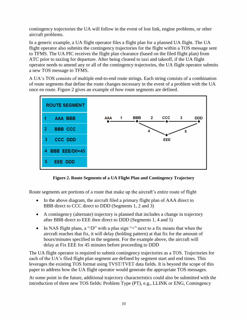
A UA’s TOS consists of multiple end-to-end route strings. Each string consists of a combination
of route segments that define the route changes necessary in the event of a problem with the UA
once en route. Figure 2 gives an example of how route segments are defined.
Figure 2. Route Segments of a UA Flight Plan and Contingency Trajectory
Route segments are portions of a route that make up the aircraft’s entire route of flight
In the above diagram, the aircraft filed a primary flight plan of AAA direct to
BBB direct to CCC direct to DDD (Segments 1, 2 and 3)
A contingency (alternate) trajectory is planned that includes a change in trajectory
after BBB direct to EEE then direct to DDD (Segments 1, 4 and 5)
In NAS flight plans, a “/D” with a plus sign “+” next to a fix means that when the
aircraft reaches that fix, it will delay (holding pattern) at that fix for the amount of
hours/minutes specified in the segment. For the example above, the aircraft will
delay at Fix EEE for 45 minutes before proceeding to DDD
The UA flight operator is required to submit contingency trajectories as a TOS. Trajectories for
each of the UA’s filed flight plan segment are defined by segment start and end times. This
leverages the existing TOS format using TVST/TVET data fields. It is beyond the scope of this
paper to address how the UA flight operator would generate the appropriate TOS messages.
At some point in the future, additional trajectory characteristics could also be submitted with the
introduction of three new TOS fields: Problem Type (PT), e.g., LLINK or ENG, Contingency

11
Activation Time (CAT), and MRT. Figure 3 shows an example of a filed flight plan as well as
associated TOSs associated with the filed flight plan (the new required fields are outlined in red).
Figure 3. Example of UA Filed Flight Plan and Contingency Trajectories
The UA flight operator can submit an updated TOS to TFMS to update the TVST and TVET for
each flight segment to reflect any changes due to revised estimates due to departing later than
proposed, winds aloft different from forecast, or ATC-issued clearances. Changing the TVST
and TVET to reflect the actual departure time could be an automated process for UA aircraft
types, by adjusting these values by actual departure time minus the proposed time of departure.
Figure 4 shows the updated TOS TVST/TVET times based on the UA departing 7 minutes after
proposed time of departure.
Figure 4. TVST and TVET Updated to Reflect Actual Departure Time
When a UA senses C2 link is lost with the PIC or other contingency situation requiring the
execution of a contingency trajectory, the UA could set its transponder to a special-purpose
beacon code.7 The lost link beacon code would cause a prominent indication in the UA data
block on the controller display,8 informing ATC of the contingency situation. Other special-
purpose emergency beacon codes could also be defined or the UA might be able to make use of
the three existing emergency beacon codes, so UAs could inform ATC of other problem types.
When an en route controller notices a lost link or other problem beacon code in a UA datablock,
the controller notifies the front line manager (FLM) of the UA contingency situation.
7 Today unmanned aircraft would squawk 7600, the special purpose beacon code signifying a loss of ATC communications. It is
expected that a new special purpose emergency beacon code will be defined to specifically indicate a loss of a UAS command
and C2 link. The beacon code of 7400 is being explored. If an unmanned aircraft is experiencing a contingency other than a
loss of a command and C2 link it would most likely squawk either 7600 or 7700 (emergency). 8 This would require additional ERAM modifications.

12
The FLM then notifies a traffic management coordinator (TMC) or looks up the UA flight plan
in TFMS to read the TOS. The FLM or TMC identifies appropriate trajectory option from the
UA’s current TOS in TFMS by matching the current time with the TVST/TVET and the PT.
Figure 5 shows the correct contingency option that the FLM or TMC would select, based on the
current time being 1938 at the time of the lost link.
Figure 5. Applicable Contingency Trajectory for Current Time of 1938
Next, the FLM or TMC enters selected trajectory option (current contingency trajectory) into the
TFMS ABRR Route Amendment dialog box and sends the contingency trajectory to the
controller through TFMS to ERAM ABRR reroute functionality. Figure 6 gives a notional view
of the TFMS route amendment dialog box with the FLM/TMC inserted selected contingency
route.
Figure 6. Notional TFMS Route Amendment Dialog Box (Modified from [5])
When the controller receives the UA contingency route amendment in ERAM, the route is not
yet incorporated into the ERAM flight plan route of flight. The controller can trial-plan (see
Section 2.2.2.2) the UA contingency trajectory route and altitude for potential conflicts and then

13
enter the amended route and altitude into the ERAM flight plan. After that, the controller
monitors the actual UA track for future conflicts (aircraft-to-aircraft and SAA probe) and to
ensure it follows the pre-coordinated, expected contingency trajectory. Figure 7 shows a notional
example of what the en route controller’s D-side Graphic Plan Display (GPD) and plans display
may look like when no conflict is detected.
Figure 7. Notional ERAM Controller GPD without Conflict Detected (Modified from [5])
When the controller is notified by the UA PIC (via air-ground or ground-ground communication)
that the contingency situation is resolved, the controller can receive the updated route request
directly from UA flight operator. Alternatively, the UA PIC can coordinate with the controller
that the PIC is updating the TOS to reflect the new, revised, route with the route start time. If the
UA flight operator has updated the TOS with this new nominal route, the controller informs the
FLM, the FLM either advises the TMC or retrieves the new, revised, nominal route from UA
updated TOS. The FLM or the TMC enters the selected trajectory option (revised nominal
trajectory) into the TFMS ABRR reroute dialog box. The FLM or TMC then sends new nominal
trajectory to ATCS through TFMS to ERAM ABRR reroute functionality. The controller
observes the UA contingency route amendment received in ERAM from TFMS, selects the
received contingency route to amend UA flight plan, and trial-plans the UA contingency route
for conflicts. If ground to ground PIC/ATC communications are available or when 2-way voice
communications are re-established, if there is a conflict, the controller has the option to revise
the UA’s trajectory to resolve the conflict. The controller then issues the UA PIC an ATC
clearance for the new route, enters the amended route into the UA’s ERAM flight plan and
monitors the actual UA track the same as with other flights.
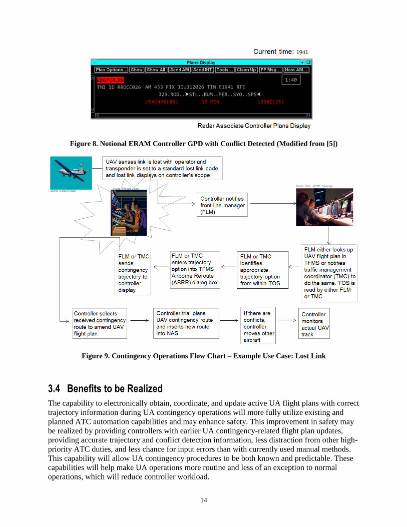
In the case where there is a conflict detected, when the en route controller conducts a trial-plan of
the UA PIC’s requested new nominal route, the controller would observe that the reroute
problem status indicates the conflict. For example, if this is due to a predicted aircraft-to-aircraft
problem, the controller may choose to either amend the UA clearance or adjust the trajectory
(clearance) of the other aircraft. Figure 8 shows a notional example of what the en route
controller’s plans display may look like when there is a conflict detected. Figure 9 is a flow chart
of the entire process once the UA encounters a problem and will be flying a contingency route.
14
Figure 8. Notional ERAM Controller GPD with Conflict Detected (Modified from [5])
Figure 9. Contingency Operations Flow Chart – Example Use Case: Lost Link
3.4 Benefits to be Realized
The capability to electronically obtain, coordinate, and update active UA flight plans with correct
trajectory information during UA contingency operations will more fully utilize existing and
planned ATC automation capabilities and may enhance safety. This improvement in safety may
be realized by providing controllers with earlier UA contingency-related flight plan updates,
providing accurate trajectory and conflict detection information, less distraction from other high-
priority ATC duties, and less chance for input errors than with currently used manual methods.
This capability will allow UA contingency procedures to be both known and predictable. These
capabilities will help make UA operations more routine and less of an exception to normal
operations, which will reduce controller workload.

15
4 Summary of Impacts
4.1 Operational Impacts
The capability to electronically obtain, coordinate, and update active UA flight plans with correct
trajectory information during UA contingency operations may enhance safety. This improvement
in safety may be realized by providing controllers with earlier UA contingency-related flight
plan updates, providing accurate trajectory and conflict detection information, less distraction
from other high-priority ATC duties, and less chance for input errors than with currently used
manual methods. This capability will allow UA contingency procedures to be both known and
predictable.
There will also be a sharing of tactical, operational responsibility between the controller, FLM
and TMC whereas prior to this capability, most or all of the tactical operational responsibility
belongs to the controller. There will also be a change of responsibility of UA flight operators to
file and update TOSs to reflect current contingency trajectories whereas prior to the capability,
UA flight operators relied on more manual methods of coordinating contingency trajectories with
ATC as defined in UA flight operators’ FAA-approved COAs.
Finally, while this paper presents a detailed concept of operations and speculates on the potential
operational benefits from ATM perspectives, analysis was not conducted on how these benefits
might impact UAS operators in terms of relaxation of operational limitations, flexibility in COA
approvals, etc.
4.2 System Impacts
The capability described in this concept of operations could be realized with limited or no
changes to TFMS, ERAM, or other FAA automation systems. This assessment is based on the
included references for FAA automation [2] [3] [4] [5] and the assumptions previously outlined.
This concept will need to be reviewed as more detailed FAA automation plans are developed.
Additionally, if three additional fields could be added to the definition of the TOS (as optional
fields), more refined information could be available to provide ATC with trajectory
characteristics regarding: PT, e.g., LLINK or ENG, CAT, and MRT. These three additional
fields are not necessary to achieve the majority of the capabilities described in this concept of
operations.
A potential negative impact is that if a UA with contingency trajectories in its TOS became
subject to a TMI, which was using TOSs to assign reroutes and EDCTs, the UA could potentially
be assigned a reroute or EDCT, when the trajectories in the TOS were not designed for this
purpose. This potentially negative impact could be mitigated through procedures that require UA
flight operators to be aware of and avoid locations in the NAS where TMIs using TOSs are
occurring or are expected to occur. A second potential mitigation option could be to introduce
requirements for TFMS automation to ignore the TOS in UAs when analyzing and computing
these types of TMIs and instead assign UAs reroutes and/or EDCTs that are not generated from
use of the UA TOS. A third potential mitigation strategy for precluding the use of UA TOSs for
TMI-related purposes would be to filter out UAs out of FEAs and FCAs upon which TOS-
related TMIs are based. To avoid being issued a reroute by CTOP, UA operators could also
submit TOS with the maximum RTC allowable for each contingency route. This would
significantly decrease the likelihood that CTOP assigns a submitted contingency route as a
reroute.

16
Finally, as previously mentioned, UAS operators will likely need to develop automation changes
in order to generate contingency TOS messages from the stored contingency routes in mission
planning and other flight control systems. Analysis of the automation changes required was
beyond the scope of this research, but will likely be critical to this concept.

17
5 References [1] FAA, Integration of Unmanned Aircraft Systems into the National Airspace System
Concept of Operations, V2.0, September 28, 2012.
[2] Traffic Flow Management-Modernization (TFM-M) Program, Traffic Flow Management
System (TFMS) Collaborative Trajectory Options Program (CTOP) Interface Control
Document (ICD) for the Traffic Flow Management-Modernization (TFM-M) Program,
Version 3.0, November 2012.
[3] CSC, Collaborative Trajectory Options Program (CTOP) Interface Control Document
(ICD) for the Traffic Flow Management System (TFMS), Version 2.3, October 18, 2011,
Prepared for U.S. Federal Aviation Administration by CSC, North American Public
Sector – Civil Group, Rockville, MD.
[4] Volpe, CACR Industry Day Technical Briefing, CTOP Assignment Algorithm and
Substitutions, Cambridge, MA, November 2011.
[5] Bowen, K. C. et al., Concept of Operations for Executing Initial TFM-Initiated Airborne
Reroutes in the 2014 Timeframe, MTR110155R3, McLean, VA, September 2012.

A-1
Appendix A Glossary
Acronym Definition
ABRR Airborne Reroutes
ARTCC Air Route Traffic Control Center
ATC Air Traffic Control
ATCS Air Traffic Control Specialist
ATM Air Traffic Management
C2 Command and Control
CAT Category
CATMT Collaborative Air Traffic Management Technologies
COA Certificate of Authorization
EDCT Expect Departure Clearance Time
ERAM En Route Automation Modernization
ERIDS En Route Information Display System
FAA Federal Aviation Administration
FCA Flow Constrained Area
FEA Flow Evaluation Area
FL Flight Level
FLM Front Line Manager
FSM Flight Schedule Monitor
GPD Graphic Plan Display
IFR Instrument Flight Rules
MRT Manual Restore Time
NAVAID Navigational Aid
NextGen NextGen Air Transportation System
NTML National Traffic Management Log
PIC Pilot in Command
PT Problem Type
RMNT Required Minimum Notification Time
RTC Relative Trajectory Cost
SAC-EC Special Airworthiness Certificates – Experimental Category
TFM Traffic Flow Management
TFMS Traffic Flow Management System

A-2
Acronym Definition
TMC Traffic Management Coordinator
TMI Traffic Management Initiative
TOS Trajectory Option Set
TSD The Traffic Situation Display
TVET Trajectory Valid End Time
TVST Trajectory Valid Start Time
UA Unmanned Aircraft
UAS Unmanned Aircraft System
URET User Request Evaluation Tool
WP Work Package

Disclaimer
Approved for Public Release. Distribution Unlimited. Case Number 13-3449.
The contents of this material reflect the views of the author and/or the Director of the Center for
Advanced Aviation System Development (CAASD), and do not necessarily reflect the views of
the Federal Aviation Administration (FAA) or the Department of Transportation (DOT). Neither
the FAA nor the DOT makes any warranty or guarantee, or promise, expressed or implied,
concerning the content or accuracy of the views expressed herein.
.
©2013 The MITRE Corporation. All Rights Reserved. The Government retains a nonexclusive,
royalty-free right to publish or reproduce this document, or to allow others to do so, for
“Government Purposes Only.” For further information, please contact The MITRE Corporation,
Contract Office, 7515 Colshire Drive, McLean, VA 22102 (703) 983-6000.