FLIGHT ASSESSMENT OF A LARGE SUPERSONIC ... sale by the National Technical Information Service,...
58
NASA TECHNICAL MEMORANDU M CM CO NASA TM X-3259 IS* FLIGHT ASSESSMENT OF A LARGE SUPERSONIC DRONE AIRCRAFT FOR RESEARCH USE Clinton V. Eckstrom and Ellwood L. Peele Langley Research Center Hampton, Va. 23665 NATIONAL AERONAUTICS AND SPACE ADMINISTRATION • WASHINGTON, D. C. • DECEMBER 1975 https://ntrs.nasa.gov/search.jsp?R=19760004954 2018-06-19T09:07:44+00:00Z
Transcript of FLIGHT ASSESSMENT OF A LARGE SUPERSONIC ... sale by the National Technical Information Service,...

N A S A TECHNICAL
MEMORANDU M
CMCO
NASA TM X-3259
IS*
FLIGHT ASSESSMENT OF A LARGE SUPERSONIC
DRONE AIRCRAFT FOR RESEARCH USE
Clinton V. Eckstrom and Ellwood L. Peele
Langley Research Center
Hampton, Va. 23665
NATIONAL AERONAUTICS AND SPACE ADMINISTRATION • WASHINGTON, D. C. • DECEMBER 1975
https://ntrs.nasa.gov/search.jsp?R=19760004954 2018-06-19T09:07:44+00:00Z

1 Report No.
NASA TM X-32592. Government Accession No. 3. Recipient's Catalog No.
4. Title and Subtitle
FLIGHT ASSESSMENT OF A LARGE SUPERSONICDRONE AIRCRAFT FOR RESEARCH USE
5. Report Date
December 19756. Performing Organization Code
7. Author(s)
Clinton V. Eckstrom and Ellwood L. Peele8. Performing Organization Report No.
L-10333
9. Performing Organization Name and Address
NASA Langley Research CenterHampton, Va. 23665
10. Work Unit No.
505-02-22-0111. Contract or Grant No.
12. Sponsoring Agency Name and Address
National Aeronautics and Space AdministrationWashington, D.C. 20546
13. Type of Report and Period Covered
Technical Memorandum14. Sponsoring Agency Code
15. Supplementary Notes
16. Abstract
An assessment is made of the capabilities of the BQM-34E supersonic drone
aircraft as a test bed research vehicle. This assessment is made based on a flight
conducted for the purpose of obtaining flight-test measurements of wing loads at
various maneuver flight conditions. Flight plan preparation, flight simulation, andconduct of the flight test are discussed along with a presentation of the test data
obtained and an evaluation of how closely the flight test followed the test plan.
17. Key Words (Suggested by Author(s)|
DronesFlight operations
18. Distribution Statement
Unclassified — Unlimited
Subject Category 0519. Security Classif. (of this report)
Unclassified20. Security Classif. (of this page)
Unclassified21. No. of Pages
5522. Price"
$4.25
For sale by the National Technical Information Service, Springfield, Virginia 22161

FLIGHT ASSESSMENT OF A LARGE SUPERSONIC
DRONE AIRCRAFT FOR RESEARCH USE
Clinton V. Eckstrom and Ellwood L. Peele
Langley Research Center
SUMMARY
Drone-type aircraft are being used by NASA as free-flight research vehicles for the
measurement of steady and unsteady loads on aircraft structures and/or active control systems.A flight test was conducted using a BQM-34E supersonic drone aircraft to measure wing loadsat various flight-test conditions. This report presents information related to the preparationof a flight plan for and the conduct of such a research flight test in order to evaluate theuse of a drone aircraft as a research flight-test vehicle. The flight-test data obtained are dis-
cussed along with an evaluation of how closely the flight test followed the flight plan.
INTRODUCTION
Aircraft aerodynamic and structural test data have been obtained over the years through
many different techniques, the principal1 ones being scale-model wind-tunnel tests and full-scale
piloted aircraft tests. Recent advances in unmanned, drone-type aircraft offer an additional
method of testing with several potential advantages. Specifically, a supersonic target drone-
type aircraft is being used by NASA as a free-flight research vehicle for technology advance-
ment, such as the measurement of steady and unsteady loads on experimental aircraft struc-
tures and/or active control systems. Of primary consideration is the flight evaluation of
different wing planforms and new wing designs as discussed in reference 1. Flight tests ofnew systems on the drone-type aircraft are an intermediate step between tests of scaled wind-
tunnel models and tests on full-scale piloted aircraft. The use of such aircraft is warranted
where there is a high risk potential or where lowered costs would result. Many of the initialresearch efforts planned are focused on the transonic speed range since wind-tunnel testing is
especially difficult in this region.
It is anticipated that the primary data to be acquired during the flight tests would be
measurements of pressure distributions, local accelerations, and structural loads imposed on theexperimental wing and/or control surfaces at specified flight-test conditions. It was desirable
therefore to gain experience in conducting such experiments aboard a drone aircraft and to
establish the type and quality of data that would be attained from such a flight test.

The drone flight test discussed herein was conducted at the Naval Missile Center, Point
Mugu, California. The test vehicle was a standard Navy BQM-34E drone aircraft (supersonic
Firebee II) on which NASA had installed four strain gage bridges on the left wing. The
purposes of the flight test were: (1) to obtain measurements from the strain gage bridgesat several flight loading conditions (vertical load factors ranging from Ig to 5g) from which
wing structural loads were to be determined, and (2) to evaluate the capabilities of a drone-
aircraft operation (i.e., that it can be utilized to meet the requirements of a prepared flight
plan).
The specific flight plan was developed primarily for later use with a standard dronewing instrumented to measure differential pressure distribution on the right wing semispan
and structural loads from strain-gage-bridge outputs on the left semispan. For this reason the
flight plan included several straight and level steady flight conditions in addition to quasi-
steady maneuvers which were used to attain the higher g loading conditions. The straightand level flight runs were for specific Mach number and angle-of-attack conditions. The
maneuvers consisted of pull-ups following dives and sustained high g turns. The maneuverswere conducted over a wide range of altitude and angle-of-attack conditions.
The purpose of this report is to document the results of a drone-type flight operation
performed for research-flight-testing purposes and to provide an indication of the type and
extent of the data obtainable from such a flight test. An evaluation of the experiment to
measure wing structural loads is presented in reference 2.
SYMBOLS
Values are given in both SI and U.S. Customary Units. The measurements and calcu-
lations were made in U.S. Customary Units.
c; wing mean aerodynamic chord, 1.195 m (3.92 ft)
CL lift coefficient
CT lift coefficient due to rate of change of pitch angle, per degree per secondLq
CT lift coefficient due to angle of attack, per degreeLa
Cf lift coefficient due to angle of attack including effects of aircraft elasticity,a Aper degree
CT lift coefficient due to the rate of change of angle of attack, per degree per second

CL lift coefficient due to elevon deflection, per degree
C^j normal-force coefficient
g acceleration due to gravity, 980 m/sec^ (32.2 ft/sec^}
M Mach number
nz normal load factor
q pitch rate, deg/sec
5 wing gross planform area, m (,ft j
t flight time, sec, min, or min:sec
T thrust, N (Ibf)
V velocity, m/sec (ft/sec)
W total aircraft weight, N (Ibf)
X,Y Cartesian axes (see fig. 4)
a. angle of attack, deg
«o angle of attack at zero lift, deg
a rate of change of angle of attack, deg/sec
6 elevon deflection, deg
p atmospheric density, g/irr (slugs/ft-*)
0C AFCS commanded aircraft roll angle, deg

FLIGHT-TEST EQUIPMENT
Drone Vehicle
The BQM-34E drone is a turbojet-powered, supersonic, recoverable aircraft developed asa target vehicle for the U.S. Navy. A three-view drawing of the aircraft is shown in figure 1
and an inboard profile is presented as figure 2. The aircraft is capable of flight at a wide
range of Mach numbers up to M = 1.8 at near maximum altitude and to M = 1.1 at
sea level as shown in the flight envelope of figure 3. The fuselage-mounted external fuel
tank must be jettisoned before beginning supersonic flight.
Instrumented Wing
The left wing of the Navy BQM-34E drone was instrumented with strain gage bridges
at four locations as shown in figure 4. A loads calibration was performed where the elec-
trical output of the strain gage bridges was measured for various conditions of shear, bending
moment, and torsion loads imposed by the calibrate weights which were applied to various
locations on the wing. Load coefficients were then derived by means of a regression analysis
for use with measured strain-gage-bridge outputs. It was anticipated that shear, bending
moment, and torsion loads in the wing structure could be determined using the load coeffi-cients and the strain-gage-bridge outputs measured during the flight test. Additional informa-
tion concerning the strain-gage-bridge installations, the loads calibrations, and the derivation
of loads equations is presented in reference 2.
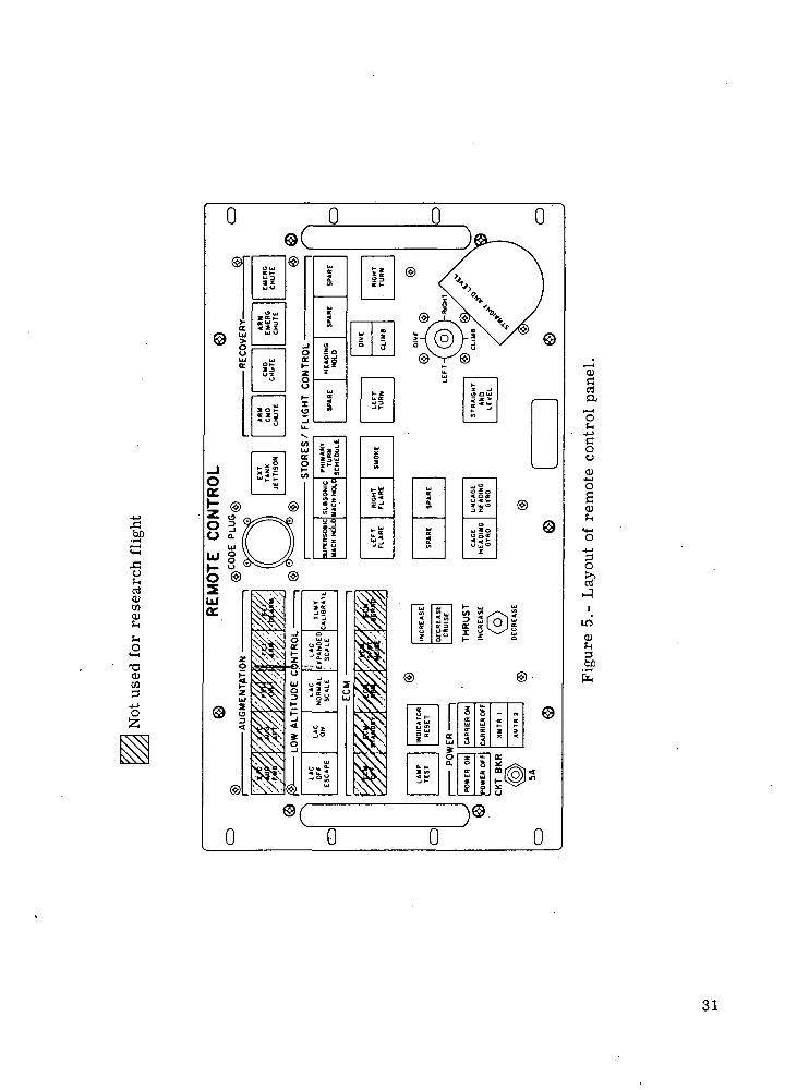
Remote Control. System
The BQM-34E drone aircraft is controlled during flight from a control center by means
of discrete radio command signals sent to an onboard automatic flight control system (AFCS).The AFCS stabilizes the aircraft about the pitch, yaw, and roll axes and provides attitudeand flight-path control. A layout of the flight control panel used by the remote control
operator (RCO) at the control center is presented as figure 5 which shows the flight control
commands available to the RCO. The responses of the drone to the commands of the RCOare generally time-rate controlled by the AFCS; for example, the thrust increases or decreases
corresponding to a rate of change of engine speed (rpm) of 1 percent for each second of
command time, and the dive and climb commands result in a rate of change of pitch attitude
of 1.8° per second of command time. The AFCS also has a minimum allowable engine
speed (rpm setting) and maximum allowable dive and climb angles beyond which the vehicle
cannot be commanded. To aid in control, the RCO has available radar-track information pre-
sented on plotboards and performance data received by telemetry from the drone on strip
charts and on a remote indicator panel such as shown in figure 6. A photograph of a
typical control center is presented as figure 7.

FLIGHT SIMULATION PROGRAMS
Two different flight simulation programs were used in preparation for the drone-aircraft
flight test discussed herein. The first of these was the six-degree-of-freedom digital computerprogram established by the Naval Missile Center (NMC) and the second was an analog pro-
gram developed and used by the aircraft manufacturer as a real-time simulator for training
purposes.
Digital Flight Simulation Program
The NMC six-degree-of-freedom digital computer jprogram1 was used to assist in estab-lishing details of the flight plan as will be discussed later. A generalized block diagram of
the simulation program is given in figure 8. Note that the flight control system, the aero-
dynamic forces and moments, the vehicle physical characteristics, and power plant thrust and
fuel flow are programed as separate subroutines. Thus, if a new wing and/or control systemwas used on the drone, the required modifications to the simulation program could be maderelatively easily.
The computer simulation program uses each of the flight control commands available
to the RCO as command inputs to the simulation program. The program also requires
information on the initial flight conditions, the initial vehicle configuration parameters, and
the initial control position settings for any given run in addition to several miscellaneous
inputs to assure proper processing and presentation of the calculated data.
Analog Flight Simulation Program
The analog simulation program was used to train the RCO for the specific requirements
of this flight test using real-time inputs from a flight control panel as was shown in figure 5.Flight information determined by the simulation program was displayed both on strip charts
and on a remote indicator panel (fig. 6).
FLIGHT-PLAN PREPARATION
The flight plan selected for this flight test was one which was prepared for flight test-
ing a new drone wing being instrumented by NASA for measurement of differential pressures
between the upper and lower wing surface and with strain gage bridges calibrated to provideloads measurements.
1 Programed in FORTRAN for IBM 7090/7094 Direct Coupled System with a conver-sion for use with CDC 6600 computer system.

For flight testing the new wing, measurements are required at two types of flight condi-tion. One would be a straight and level steady-state flight condition with Mach number and
angle of attack as varying parameters. The other type flight condition would be quasi-steady
maneuvers to provide a variation of aircraft loading conditions. Although the drone wingflown on the flight test reported herein did not have differential-pressure measuring instru-
ments, a purpose of the flight was to evaluate the capability to achieve each of the flight
conditions specified.
For the straight and level steady-state test conditions, the RCO controls the drone
flight Mach number by changing the engine speed and therefore the thrust level; however, the
angle of attack at which the drone will fly is set by the onboard AFCS as required to main-
tain level flight. The digital simulation program was used to determine at what altitude the
drone would fly at the desired angle of attack for the test condition. An angle of attack
of 2° had been selected for the various runs. Priority had been set on attaining test condi-
tions in the transonic speed range and thus Mach numbers of 0.80, 0.85, 0.90, 0.95, 1.06,
and 1.10 were selected. The drone aircraft was to cruise for 2 min at an angle of attack
of 2° at each of these Mach numbers.
The standard quasi-steady maneuver for attaining symmetrical aircraft loadings with
piloted aircraft has been to perform a pull-up maneuver from a diving flight condition. The
drone aircraft, however, has safeguards built into the AFCS to prevent abrupt changes inpitch attitude. Therefore the highest loading attainable with a standard AFCS from a pull-upmaneuver is on the order of 2g even when the pull-up is initiated from a diving flight
condition. Higher loads can be achieved, however, during turning maneuvers. Specifically, ifturns are performed below a 4.57-km (15 000-ft) altitude with the AFCS in the "primary-turn" and "altitude-hold" modes, the drone will perform a constant-altitude g-controlled
turn at 3g with the external fuel tank on and at 5g with the external fuel tank off.
Sustained accelerations of lesser magnitude will result from turns at other flight conditions.
Because the wings have no control surfaces (control is by means of elevens) and the turns
are "coordinated" (i.e., performed at a constant bank angle and flight altitude - pitch
variation is the primary method of altitude control), it was considered that the loading on
both wings would be essentially symmetrical and equal to, and therefore similar to, the loads
encountered during a pull-up maneuver. Turn maneuvers were therefore included in the flight
plan in addition to pull-up maneuvers to achieve the desired range of symmetrical aircraft
loading conditions.
Once the test conditions to be included in the flight plan had been established, a
rough outline of the test plan was drawn up. The various steps of the flight plan were then
simulated using the six-degree-of-freedom digital program mentioned earlier. The digital
simulation program was used to assure that the following conditions could be met:

1. That the proposed flight plan allowed sufficient time and fuel for accomplishing the
desired flight maneuvers.
2. That the drone-aircraft flight angle of attack would be within 2° ± 0.2° for each
of the six cruise conditions.
3. That the proper relationship between flight conditions could be established so that
turns could be accomplished to keep the flight within test-range boundaries and that the
flight would terminate within the normal recovery area.
4. That most efficient use was made of fuel available in the external fuel tank since itis necessary that the external fuel tank be jettisoned before beginning supersonic flight.
A listing of the flight plan based on the results of the six-degree-of-freedom digital
simulation program is presented in table I and a plan view of the proposed flight is presented
in figure 9. Using this proposed flight plan, the remote control operators practiced flying
the mission in "real time" on an analog simulator to assure that they would be capable of
accomplishing the required control tasks within the time, distance, and fuel allotments estab-
lished. Note that the flight plan listed in table I does not include details associated with
the dive and pull-up maneuvers (flight segments 15 to 21). An additional purpose of the•
RCO practice on the analog simulator was to work out the best sequence for the perfor-
mance of these maneuvers.
After the successful completion of the practice flights on the analog simulator, the final
flight-test-plan document was prepared. This document contained flight-plan listings (including
the dive and pull-up maneuvers) and plan views of the proposed flight both for a ground
launch of the drone and for an air launch from a P-2V aircraft. These flight-plan listings
and plan views are presented as tables II and III and figures 10 and 11, respectively. Themost significant difference between the initial flight plan prepared for a ground launch and
the final ground-launch flight plan was changing two of the right turns (heading changesof 35° and 90°) to left turns (heading changes of 325° and 270°, respectively) and theaddition of a full 360° right turn near the end of the flight. The right turns were changed
to left turns to increase the interval of time in the turn during which the aircraft wouldbe in a g-controlled, constant-altitude condition during which symmetrical wing loading wouldbe encountered. The 360° right turn at the end of the flight was added to give at least
one turn maneuver that would produce a 5g aircraft loading.
The flight plan developed for the air-launch condition varied somewhat from the
ground-launch flight plan primarily because of the different starting point and flight azimuth
selected. The longer duration turns came at the second and third turns rather than at the
first and second turns as was the case for the ground-launch flight plan. The air-launch
flight plan was the one actually used for this flight test.

FLIGHT TEST
The drone vehicle was air launched at a 2.44-km (8000-ft) altitude from a P-2V air-
craft. The drone is shown, prior to flight, suspended from the left wing of the P-2V aircraft
in figure 12. The drone was launched at 21:25:06.0 GMT and the flight lasted a total
of 31 min.
A comparison of the actual flight plan view with the one originally prepared for an
air-launch flight test is shown in figure 13. The major differences are the changes in azimuthheading which occurred on the first leg of the flight plan and the downward and outward
shifting of the last two legs of the flight plan. The flight-path azimuth change that occurred
on the first leg near the end of flight segment number 2 was to avoid aircraft which
appeared to be intruding the airspace allotted for the drone flight test. An additional azimuth
change was then necessary as the drone approached San Nicolas Island since no drone flights
are allowed over any of the inhabited islands in the test range. The shifting of the last two
legs of the flight plan was done in an attempt to provide a slightly better position for the
final recovery of the drone at the completion of the flight test.
The external fuel pod was jettisoned at 15 min:36.3 sec into the flighto test with only
60 N (13.4 Ibf) of fuel remaining or 3.35 percent of its capacity. The flight plan had
called for the external tank to be released about 1 min later (t = 16 min:35 sec) with
about 138 N (31 Ibf) of fuel remaining or slightly less than 8 percent of the capacity.
The normal drone recovery sequence was initiated after 30 min:59.2 sec of flight
(within 41 sec of when called for in the test plan) when the drone aircraft was at an alti-
tude of 4.1 km (13 500 ft) and a Mach number of 0.92. There were 285 N (64.1 Ibf)of fuel remaining in the main fuel tank when the recovery sequence was initiated as com-pared to the estimate of 111 N (25 Ibf) of fuel remaining per the flight plan. (The main
fuel tank has a capacity of 1170 N (263 Ibf) of fuel.) Initiation of the recovery sequenceautomatically shut down the engine by cutting off the fuel supply. Because the drone wasbelow a 4.57-km (15 000-ft) altitude and the Mach number was less than 0.94, the AFCS
initiated a 16° pitch-up maneuver which resulted in a climb to an altitude of nearly
5.79 km (19 000 ft). The "emergency-chute" command signal was also sent as listed intable IV at 31 min:44.2 sec (45 sec after the "command chute" signal was sent) as a
routine backup procedure (no malfunction of the primary chute command was noted). Thedrag parachute deployed at approximately 31 min:52 sec and the main parachute deployed
at approximately 32 min: 15 sec for a normal recovery operation. After water impact, a
salt-water switch initiated firing of explosive bolts to release the parachute. The recovery
helicopter, which was stationed in the recovery area, then picked up the drone and returnedit to NMC.

Except for the minor changes mentioned, the flight test was accomplished essentially asplanned. A complete listing of all commands sent by the RCO, the time of the commands,
and the duration of the commands is presented in table IV.
TEST DATA
Telemetered drone performance data were received on a continuous basis during the
flight test. This information was displayed on the RCO display panel (shown in.fig. 6) andalso recorded on strip charts and magnetic tape. Continuous telemetry data were
also received from the four strain gage bridges located on the drone wing. Two FPS-16
radar sets were used to beacon-track the drone aircraft during the flight test. One of these
radars was located at Point Mugu and the other was located downrange on San Nicolas
Island. Altitude and range-position data from both radars were displayed at the control center
during the flight test. The data package provided by the test range included: (1) a digital
listing of all the drone performance and strain-gage-bridge measurements telemetered from thedrone aircraft, (2) a listing of atmospheric data as measured by a rawinsonde launched
1 hr:35 min after initiation of the drone flight test, and (3) a digital listing of altitude,
Mach number, velocity, acceleration, flight-path angle, impact pressure, and dynamic pressureas determined from the FPS-16 radar-track data used in conjunction with the measured atmo-spheric data.
Mach Number and Altitude Data
A comparison of the Mach number and altitude data as determined by the FPS-16
tracking radar with measurements made onboard the drone aircraft is presented as a functionof flight time in figure 14. As can be seen from the figure there is close agreement between
the onboard and radar measurements for the entire flight with the exception of three intervals.These are: (1) from 1 to 3 sec flight time when the drone was flying at less than a
1.2-km (4000-ft) altitude, (2) when the drone was flying at or near transonic velocity
(0.98 < M < 1.05), and (3) near the end of the flight test where the radar-determined Mach
number appears to be in error for about 14 sec at the start of the last dive and pull-up
maneuver and again for about 50 sec during the 360° 5g right-turn maneuver.
It was noted in the test-range data package that radar tracking data for altitudes below1.2 km (4000 ft) are extremely unreliable because of the low or negative elevation angles
from the tracking radar to the drone target. Therefore during the interval from 1 to 3 sec
flight time, when the drone was at less than the referenced altitude, the radar-track data
were not considered useful for analysis purposes (at one point during this interval the radar-
track data indicated a negative flight altitude). However, when the drone was flying at tran-
sonic velocities (0.98 < M < 1.05) it is the onboard measurements which are considered tobe in error because of the inability of the onboard computer to determine adequately either

Mach number or altitude from pitot-static tube measurements because of shock-wave interfer-
ence effects. Step changes in the onboard measurements of Mach number and altitude oc-
curred at t = 16 min:30 sec, 17 min:00 sec, 17 min:25 sec, 18 min:20 sec, 18 min:40 sec,
23 min:05 sec, and 23 min:17 sec. No immediate explanation is available for the apparent
error in Mach number as determined from radar-track measurements for the intervals from
t = 28 min:34 sec to 28 min:48 sec and from t = 29 min:45 sec to 30 min:35 sec.
The altitude measurements as determined by the radar data during these intervals are in close
agreement with the measurements from onboard the drone aircraft even when the altitude
was changing rapidly during the first interval. It is apparent however, that the radar measure-
ments of Mach number are in error and therefore should be excluded from the data analysis
during these two time intervals.
Steady-State Cruise Conditions
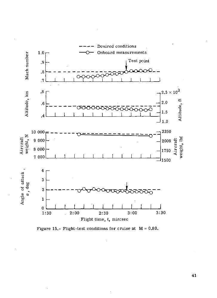
Figures 15 to 20 present the onboard measurements of flight Mach number and altitude,
the drone-aircraft weight as determined from the preflight gross-weight measurement and the
onboard measurement of the weight of fuel used, and the onboard measurement of vehicle
angle of attack for each of the six straight and level steady-state cruise portions of the flighttest. The desired conditions are indicated by the dashed lines and the test points selected
for data analysis (table V and ref. 2) are noted by the arrows in each figure.
The first straight and level test run or cruise at M = 0.80 (fig. 15) was delayedwhile the RCO performed a left-turn maneuver to avoid piloted aircraft intruding into thetest range. The desired Mach number was achieved during the second minute of the 2-min
interval and the resultant vehicle angle of attack was on the low side, but within the desired
angle-of-attack range (a. - 2° ± 0.2°). Near the end of this first cruise interval the RCO
initiated a second turn to avoid overflying San' Nicolas Island and to bring the flight back
onto the originally planned areas of the test range.
The second straight and level test run at M = 0.85 (fig. 16) was delayed because
of the second unplanned turn just mentioned. The desired flight altitude was achieved at
about 50 sec into the test interval. The flight Mach number reached and exceeded the
desired value shortly after the flight altitude was achieved and was thereafter slightly higher
than planned. The vehicle weight was close to that predicted (within 2 percent) and the
resultant angle of attack was at times at the lower boundary (1.8°) of the desired angle-of-
attack range. The first planned right turn was initiated at t = 5 min:25 sec, which cut
short this second cruise interval. The turn was initiated at this time to maintain proper
location on the test range as shown in figure 13.
For the third straight and level test run M = 0.90 (fig. 17) the flight altitude was
held constant at about 2.13 km (7000 ft) while the Mach number was increased to the
desired value. Even though the flight altitude was slightly lower than planned, and the
10

vehicle weight was less than anticipated, the resultant angle of attack held steady at 1.8°
(the lower edge of the desired range) for about 15 sec (t = 8 min:5 sec to 8 min:20 sec).
The increase in altitude at the end of the interval resulted from a climb command initiatedto set up for the next test condition.
For the fourth straight and level test run at M = 0.95 (fig. 18) the flight altitudewas held at about 4.7 km (15 400 ft) while the Mach number was increased from 0.90up to a maximum of 0.94 for about 10 sec after which the Mach number dropped back
to 0.92. Even though the drone-aircraft weight was less than predicted during this intervaland the drone was flying higher and slower than planned, the resultant angle of attack was
generally lower than 2° and was only 1.6° to, 1.7° (less than the desired lower limit of 1.8°)when the Mach number approached the desired value at t = 10 min:40 sec.
The fifth test run or cruise at M = 1.06 (fig. 19) was performed after the external
fuel tank had been released to allow supersonic flight. However during most of the testinterval the flight Mach number was in the transonic range (0.98 < M < 1.05) where (1) the
onboard measurements of Mach number and altitude are known to be in error and (2) the
onboard automatic flight control system (AFCS) operates in the transonic mode. When the
AFCS is operating in the transonic mode, the drone will fly straight and with the wings level
but it will not maintain a constant altitude (i.e., altitude-hold mode is inactive). In this
instance the drone aircraft continued to climb slowly throughout the test interval reaching
the desired flight altitude at t = 17 min:55 sec based on radar tracking data. Radar-track
altitude and Mach number data have been included in figure 19 because of the known inac-
curacies in the onboard measurements in the transonic range already mentioned. From
about t = 17 min:30 sec to 18 min:15 sec both the onboard and radar measurements of
Mach number indicate that the Mach number was close to the desired value. Even though
the flight-test conditions of Mach number, altitude, and vehicle weight were very close to thevalues selected based on the digital drone flight-simulation program, the resulting angle of
attack was less than the desired lower limit of 1.8°.
The sixth and last straight and level test run at M = 1.10 (fig. 20) was performedat an altitude about 5 percent higher than planned. In this case the vehicle weight was
almost exactly as anticipated and the desired Mach number of 1.10 was achieved at aboutt = 21 min:30 sec. Even so, the resultant vehicle angle of attack was less (1.4° to 1.7°)than the expected range (2° ± 0.2°) based on the preflight digital simulation program.
Controlled Turn Maneuvers
Figures 21 to 24 present the onboard measurements of flight Mach number, altitude,
pitch attitude, roll attitude, angle of attack, and g loading (normal load factor) for each
of the four g-controlled turn maneuvers performed during the flight test. A g-controlled
turn is performed when the AFCS is in both the altitude-hold and primary-turn-control
11

modes and the RGO commands either a right or left turn. The drone-aircraft roll angles com-
manded for both the primary- and secondary-turn schedules are presented in figure 25. Note
that the primary-turn schedule is also a function of the drone- aircraft configuration (i.e., ex-
ternal fuel tank on or off). When a g-controlled turn is performed the resultant aircraft
loading is
cos 0C
where 0C is the commanded roll from figure 25. For altitudes below 4.57 km (15 000 ft)
the g-controlled turns are performed at a 3g level when the external fuel tank is on and at
a 5g load level when the external fuel tank is off.
The first of the four g-controlled turns (fig. 21) was a right turn initiated at
t = 5 min:25.3 sec. The right-turn command was followed immediately by a primary-turn-
schedule command. Because the AFCS was in the altitude-hold mode and the flight altitude
was less than 4.57 km (15 000 ft), the turn was a g-controlled turn performed at the 3glevel (the external fuel tank was on at this time). As can be seen from figure 21 the rightturn was performed at essentially the 3g level. During the turn the drone-aircraft roll angle
changed from 68° to a maximum of about 82° back to a minimum of 64°. The primaryright turn resulted in a larger change of direction than was desired so it was followed immedi-
ately by a left-turn command. The left turn for azimuth correction was performed accordingto the secondary- turn schedule which, at this flight altitude calls for a roll angle of 45° (see
fig. 25). From t = 5 min:55 sec to 6 min:10 sec (fig. 21) the drone aircraft did main-
tain a nearly constant roll angle of -45° while the aircraft g loading varied from 1.5gto 1.2g. The AFCS was in the altitude-hold mode during these turns (required for a
g-controlled turn) and only slight variations in altitude occurred.
The second of the four g-controlled turns (fig. 22) was a left turn followed by two
right turns to the secondary- turn schedule for azimuth correction. The flight altitude was
just slightly higher than 4.57 km (15 000 ft), therefore, the g-controlled turn was performedat about the 3g aircraft loading level. The roll angle remained fairly constant at about -75°.
Note that as the flight Mach number decreased the angle of attack was increased to maintain
the 3g loading.
The third g-controlled turn (fig. 23) was a left turn performed at supersonic velocities
(M > 1.05) after the external fuel tank had been jettisoned. As can be seen from the roll-
position curve of figure 23 the AFCS did not latch on to the turn command until the
fourth set of left-turn primary-turn-schedule commands was sent. This occurred because the
drone aircraft was initially operating in the transonic speed range (0.96 < M < 1.05) wherein
the AFCS will accept turn commands only for the duration of the command. After thesecond set of turn commands had been sent the RCO sent a straight and level command
12

(see table IV at a flight time of 19 min:00.4 sec). This command was accepted by the
AFCS because the flight Mach number was now greater than M = 1.05. The AFCS auto-
matically engages the altitude-hold mode 5 sec after the straight and level command is
received and then turn commands will latch on when received. The third turn command
was sent and released before the 5-sec interval had elapsed and therefore remained in effect
only for the duration the command was sent. When the fourth turn command was sent a
continuous g-controlled turn was performed at a nearly constant aircraft loading level of
1.9g to 2.0g while the aircraft roll angle varied from -54° to -69°. In this instance the
g-controlled portion of the turn was terminated too quickly and an additional left turn at
the secondary-turn schedule was necessary to achieve the desired azimuth heading. Note
that during this later turn the aircraft roll angle held steady at about -46° while the aircraftloading varied from 1.2g to 1.5g. During the portion of the turn performed at the secondary-
turn schedule the flight altitude held fairly constant. This was not the case during theprimary-turn-schedule portion of the turn wherein there appears to be some correlationbetween the aircraft roll angle and the altitude changes.
The fourth and last g-controlled turn (fig. 24) was a full 360° right turn performedspecifically to attain aircraft loadings at the 5g level. This turn was performed at a flight
altitude of less than 4.57 km (15 000 ft) after the external fuel tank was jettisoned. Ascan be seen from figure 24 the AFCS was unable to maintain a constant 5g aircraft loading
during the turn interval although it is obvious that the aircraft roll angle and angle of attack
were being varied in an attempt to maintain both a level flight altitude and a constant 5gaircraft loading condition. The right turn ended at slightly more than a 360° change in
heading so a left turn was initiated immediately following the right turn to provide the
desired azimuth heading. This left turn was performed to the secondary-turn schedule at
an aircraft roll angle of -45°. The flight altitude remained fairly level during both partsof the turn.
Pull-Up Maneuvers
Figure 26 presents the onboard measurements of pitch attitude, angle of attack, and
aircraft g loading during the five pull-up maneuvers performed during the flight test whichresulted in loads of about 2g.
The flight times in figure 26 can be correlated with those in figure 14 to determinethe flight-altitude and Mach number changes which occurred with each of the pull-up maneu-
vers. The first of the pull-up maneuvers occurred very near the beginning of the flight test
when the drone was diving to the first straight and level flight altitude of 0.56 km (1850 ft)from the release altitude of near 2.4 km (8000 ft). The peak loading of 1.9g came as thedrone pitched up from a nose-down attitude to a nose-up attitude. Note that it was also atthis instant that the maximum angle of attack occurred.
13

The second pull-up maneuver occurred at about three-fourths of the way through theflight test at the end of a dive from about an 11-km (36 000-ft) altitude down to an alti-
tude of a little over 3.66 km (12 000 ft). During the dive the drone aircraft was flying
at a pitch-down position of about 25°. Immediately following the climb command sent at
t = 24 min:00.9 sec the pitch attitude decreased at a nearly constant rate. It was in this
interval that the maximum loading of 2.1g occurred. This dive maneuver was also followed
by a straight and level flight interval so the maximum positive pitch angle reached wasabout 2.5°.
The first two pull-ups resulted from commands given to achieve other flight conditions
whereas the third, fourth, and fifth pull-up maneuvers were performed specifically for the
purpose of getting pull-up-maneuver loads. These last pull-ups were therefore performed in
nearly the same manner. The test plan called for these dives to be initiated from an alti-
tude of about 3.66 km (12 000 ft), a Mach number of 0.78 to 0.85, and at an engine
throttle setting of 83 to 86 percent of full throttle. The dive command was to be held
until the Mach number reached a value of 0.93 at which time the dive command was to
be released and a climb command initiated. As can be seen from figure 14, the flightMach number during these dives reached a maximum value of 0.94 for dive 3, 0.95 for
dive 4, and 0.94 for dive 5 (based on onboard measurements). Maximum aircraft loadings
of 2.0g were experienced on dives 3 and 4 and 1.9g on dive 5.
The wing strain-gage-bridge measurements were evaluated, as reported in reference 2,at 18 points of time during the flight test. The type flight maneuvers being performedat these times and the number of such maneuvers involved in the evaluation were as follows:
steady-state straight and level cruise, six
g-controlled turns, four
pull-ups, five
steady climb, one
dives, two
A listing of the flight times and the relevant telemetered data at these times is presented
in table V.
Comparisons of Vertical Force Equilibrium
For each of the test times listed in table V an evaluation was made to determine if
the forces along the aircraft body axes were in agreement as defined by the following
equation:
Wnz - T sin 8.33° =
14

where
CN = CLa(« - Oo) + CL55 + 2v(CL^ + CI
The vehicle weight W was determined from the initial vehicle weight and the onboard
measurement of the fuel used. Onboard measurements of the normal load factor nz were
available. The thrust T was determined based on the onboard measurements of engine
speed (rpm), Mach number, and flight altitude. Onboard measurements of the vehicle angle
of attack were also available. Onboard measurements of altitude and Mach number were used
in conjunction with temperature and density measurements from an atmospheric sounding
to calculate dynamic pressure. The reference area S for the standard BQM-34E drone-
aircraft configuration is 2.97 rrr- (32 ft^).
Evaluation of the normal-force coefficient C^ was based on the assumption that theaircraft angle of attack would be small and that C^ would therefore be equal to Cj^.
The lift-slope data C-^ (for a rigid aircraft) were determined based on onboard measure-ments of flight Mach number. The angle-of-attack data came from onboard measurements as
mentioned earlier but the zero-lift angles aQ were determined based on onboard measure-
ments of flight Mach number and the vehicle configuration (i.e., external fuel tank on or off).Unfortunately no flight-test measurements of 5, a, and q were available to evaluatethe remaining terms of the C^ equation. An evaluation was made of the possible relativemagnitudes of each of the remaining terms using data obtained from the digital flight-simulationprogram during preparation of the flight-test plan. From this evaluation it was concludedthat Cjs^ was primarily a function of the first term of the equation or
/"" — C*LN ~ CL
The comparison of forces based on the above data and assumptions is presented in
figure 27. As can be seen most of the data falls close to the line of agreement except for
three data points which are for the 3g and 5g turns. A review of the digital flight-
simulation program data for these turns revealed that the eleven deflections 6 were slightly
negative. Therefore if similar eleven deflections were assumed for the flight test and
the CT 6 term was included in the evaluation, then slightly better agreement would beo
attained. The contribution of the Cj^.a and Cj^ q terms, however, appeared to remainnegligible.
A rather extensive evaluation was conducted to determine what factors could account
for the discrepancy in the data for the high g turns. Because the vane-type angle-of-attack
sensor was located on an extended nose boom, consideration was given to the possibility offuselage deflection at the higher aircraft loadings. Such possible deflection would, however,
15

be in the nose-down direction which would decrease the measured angle of attack rather
than increase it as would be necessary to bring the data closer to the line of agreement.
Information was available on the effects of elasticity on the lift performance C? for botha
a trimmed and untrimmed aircraft configuration. Results using these data are presented in
figures 28 and 29. Forces measured during the high g turns are much closer to the line
of agreement but the remaining data have shifted away from the line of agreement.
It is concluded that for straight and level flight and for maneuvers resulting in aircraftload factors of 2g or less, the lift-slope data for an untrimmed rigid aircraft most adequately
describe the test data. For the high g turns the lift-slope data for an untrimmed elastic
aircraft best describe the test data.
CONCLUDING REMARKS
A flight test was conducted using a supersonic drone aircraft to measure loads atvarious flight-test conditions and to evaluate the capabilities of such aircraft as research
vehicles. The flight profile flown compared quite well with the plan originally preparedexcept for deviations required and intentionally made during the flight test. Two-minute
intervals included for attaining steady-state cruise conditions proved to be extremely useful
in that they allowed the remote control operator (RCO) time to recover from unexpected
circumstances and still achieve the test conditions. Also in some instances the RCO had
time to make necessary corrections during the test interval.
Errors did occur at times in both the radar-track and onboard measurements of flight
conditions but an evaluation of both sets of data allowed the more valid measurement to be
determined with reasonable confidence.
The automatic flight control system restraints preclude achieving aircraft load factors of
greater than 2g during pull-up maneuvers; however, load factors of up to 5g can be achieved
during symmetrical turn maneuvers.
Simulation programs were useful in defining the command sequences for the various
flight maneuvers and in determining the time,, fuel, and range requirements. However, theangles of attack achieved during the straight and level cruise portions of the flight test werelower than those predicted by the flight-simulation program particularly at the higher Machnumbers.
For straight and level flight and for maneuvers resulting in aircraft load factors of 2gor less, the lift-slope data for an untrimmed rigid aircraft most adequately describe the test
16

data. For turns where the aircraft load factors were equal to or greater than 3g, the lift-slope data for an untrimmed elastic aircraft best describe the test data.
Langley Research CenterNational Aeronautics and Space AdministrationHampton, Va. 23665August 26, 1975
REFERENCES
1. James, H. A.: Feasibility Study of Modifications to BQM-34E Drone for NASA ResearchApplications. NASA CR-112323, 1972.
2. Peele, Ellwood L.; and Eckstrom, Clinton V.: Strain-Gage Bridge Calibration and FlightLoads Measurements on a Low-Aspect-Ratio Thin Wing. NASA TN D-7979, 1975.
17

If^ Z **"> —' d ^f GO d m — m vb — oo in d vo 01
O N O N O N O N O N O N o o o o o o o o o o r - r - r - r - r -
^r —- o m o \ t - - — — C N r o r - - v . p » n r - J — oo
"i '3U, F '
nj -^ O r ^ - o o — r - r o ^ o o o o o p i r o O o o r ^ - r - G - ,
ri r-i 01 r-i 01 oJ — — — — -- — —
g - 01 r-• p- 01 oo p O r-; rn CN
Hc
' C N O J O N C N O N O J ^ O ^ O I — — 01 o oo— •— •— 01 n r-i m m m
£ . ^ o o r ^ O p Q O p O O — .- - -
r 5 o > • ' i n r - - -3 - — . . . . _£ c • — r i o) 01 01
Eo p 06 oo
% £
oi fM — — o o o o c \ O N O O r - r - r - r — r~
z
Qzo
Ou.
tua:
a.t-O
O O C-) O r-i o r-l o O 01 r-i o ("•) o
ao.= no•o i>C3 "O<u
oOv
OC X 3 O N
O O
OCA
o
tu-JCO
o o o o o o oO O O O O O O
* - r -r-O
8 8o o
8 8 s
* - *OO O O
8 ° § ° S ° §O O O O O Oif — 01 — D — (N
o o o oooO
o
c - » -aX .S <U
0 O 0o o o
or - iO C N
0 — 01 I01 01 01 '
18

U
Q
iO
06
£Qtu06
Xo
U-Jm
L
<
"a
U.
~
U.
1
n
Q
c
EID£
H
3
•
(UT3a
^
Per
cent
XQ
U
aa.
CD
00
£e
T3
3H
C0>E
r
«: cuo -o>
- S
" cS 3
£
< .1
ig" (U
conditi
on
0 o
2i
<_~;z
t«—z
E
, c
E
•p
e
F
H
C
1
3
e
E
•o
1
201
00
oo
in
r-
00
r-00
1
1
I
1
:
•1
S
.o
1 1rj
ombo
o
o
3
Laun
ch
00a*0.
r~
n
s
—
£
£
Cvm
2—
•*
00
o
o00oo
oCO
o
1
2
o
g
x>
-
ON1/1
r-i
•*
,»
^
m
n
P
K
^
!;
Sm
•3-
01
oooo
1
VO
°
oo
'i(N
— m TT v"i — r ~ f i < j \ V ) O O r ~ o o — o o o o o m ^ o o o — oo
CM M CM M N r-l _ S f _
o o m i n r - O o o r - r - i t N ^ o — • ON ON oo *n r- — • — in in O in TJ-
^ o o r - o o ^ - O o r - i m o o o o i n v O G N V o v o o o - m o o o O N r n
in .j- ^ r m m m 01 r-i CM CM 01 CM
ON oo m — — o ^" O — -• r~- o ^ i "i — oo oo CN in m o oo ^ ^o o\
• j- — Tf r-i — m ^r — — r-i fN r-i r^i r-i — —
CN Ol — ' tN ' — — — „_
o o o o o o o i r - i i i i i r-'d-T j - ' ^ r v i v o m ' r i i X b o d . ^ ^ m ' c N ' b b ^ ' X - b v o o d ^
— — ^_ _ — _ — CM r-i r-i CN r-i fN r-i 01 r-i
S 5 S - S - S S 5 2 2 S § S £ ^ S S K S S £ £
^ , 0 0 0 . o i ^ ^ o o o ^ m O T f - ^ ^ o o o o o ^ r -01 CM r-i — r-i — CM —
S S S o S S ^ ^ ^ o ^ o - ^ ^ o l S ^ S ^ S r ? r t- v o - r - r - i - r - - ^ < N - ^ o m - ^ m - o i - r i - o -
O 01 O 01 — O 01 r-i O O 01 O O r-i r-i O — O O O O O
O O O O m n-i
b b' b b — — b b b b b b bO o o O O N O N O o ^ O O ^ O N O o O O — O O O O O O O o \
0 O O O O O — — — O |
OO OO ON ON ON O — OO ON f- ON r- ON !b b b b b — — b b b b b b !
o o o o o o o o o oO O i n o O O O O O O O Om o r - O O O Q O O
— — — r- r- o *- *- " o ^ ^ o 0 * " 0 0
o o * " — O r o m m m m O r * - j O O * ' o * J o * J ^t n m O m O O O O O O O Oo o — O r - O O O o o— ^ r - p ' l O r - i o c M O
r - r s m -^- — m — in — u->— . m m
\^
(-v) ro oo ^ ,—1 . in *«o *ft *& 10 ^o^ J p . ; m ' 2 2 ^ — m — m — m
2 2 S ^~ " 1 2 ^ ^ 5 ^
OO 00 OO °°
o \o ^o •oo oo oo r-i
n u 3 1 § • - § § • 8
C - — C - — « r f C - — C ^ j _ i 3 ^ - — J ^ C - — a j g j C a j C ~ S " C ^
1 2l 5 "o i S 1 "g "5 B 2 § 1 2 • § . Ill 111"
n T T m v o r - o o o s O - c N m ^ m v o i ^ o o O N O - M m ' *r-t rs (N (N OJ
19

oD
a:oU.
QUJa.
UJoi
H
O
_J33
c^CJ
<
"ft
U.
_
3U.
—1)>C5
U
cn
Q
acE
i>
P
c:
c
' 3
jc•
t»•o
<
Pe
rce
nt
LL
au
•S5s
ofic'=sce
3
"«
O
Ca>FO>
CJn
l£
= 01
IJ
115 3C
Ue S
e0)
co
nd
itio
n
D 2
j=
2
JD
xi
n
v
_:b
c
E
"g
n
E
"a
[-1
'cd>
£oc
)
4=
F^£
-a01Un.
l o r ^ O N Q O r n r ^ — o ^ a s r ^ r N r o r i O O s r ^ v o ^ r n o i — a \ o o o o v o t n > 3 - r - i — O O N
0011*1 — a s ^ - o — o * m ^ r - r - \ o — — o o o ^ O ' ^ O ' O m ^ — r - O N m < N m o \ r J OO O s r - r ^ T } - ^ - ^ - — ^ - o o r ^ i n — — o c \ o o o o t ~ - - r - v o \ o i n i n ^ - r o f * " > r n r - j — '~ - —
l O v O t ^ C ^ ^ r ^ r ^ r ^ ^ ^ o o ^ r n r n o m r ^ T r ^ O r N ^ - ^ t r - C ^ o ^ T r i n v - i C v i n— a \ t r > T f o o N o o r - i — O f ^ c r \ ^ o t ^ i r n < N o c ^ t s - ^ o | o ^ r r s — o a\ °o r- m ^r 01 <N\ O * ^ ' ^ * ^ l ^ * 3 ' 1 ^ ' ^ l ' ^ J F r * ^ r ^ r ^ ( N r - ) n r ^ c N — — — ^- — — . — —
v n o t D t ^ Om i n r ^ ^ j - r J C \ T j - o ) ^ o r ^ o o r - r N ( N C \ c \ ^ D ' O — r ^ ^ » o n o o o \ o o J ^ j - O o i —r ^ - O ' * i * f ~ ' i — — o \ o o ^ O m m — — i O O \ o o o o r - r - \ o v o > ^ m i ^ ' ^ j ' n ^ r ^ r - j r - i — —r) c 4 ri n n n ri
O C \ c ^ o o o o o o — CT\^ F ^J - r - ^ r — o< " * i r - — r * * r * ) . r - i Q o o o o \ r ~ - o o & \ a o o o G \ & \ c > T f
r ^ i ^ o m v o r o v D ^ o o r ^ O — i r i o o w » r - i — m i O Q O r * i \ o o o o r s i i ' " ) « / i i / - ) O i ^ - u " i — oo
ro — r-J r i r - i — — — —
1 O w ^ o o o o r ^ i ^ r - w ^ m m o o o o o o o o o v ^ O N ^ t i o o \ ' ^ t ^ j ' O \ T r ^ r ^ ' ^ " — —, "o r ~ - ~ r - * v ~ t — • * f O ' < 3 ' * J r G \ m i ^ o m c \ ^ ( ^ J O \ v i r ^ T j - O o i c \ t n r ^ ^ - o > n, ~ r i m u i v i s c i o o c N — r-iro ^ j - v o r - c o o o o n o i m f ^ ^ - u ^ « n m v £ ) ^ o p * o o o o
i t n c o m c \ ' O v i i s r i « ^ O O N 1 o • ^ • • ^ • ^ D r ^ o o o o ^ - r i — — O N r ^ i o o r - O N ^ o ^ r ^ ol O r ^ ^ - O r - v o r - o a v O O - d - • ^ J - u i O \ O O O C ? \ C ^ O O O » ^ i ^ - r ^ i O O O O \ C i v O r n a \
, o w"i *o oo r-i r-1 fS f» oo oo O W ^ O O O ' — o o * o O w ^ w » O w ^ l ^ O l ' i i n r - o' O t ^ - m — < ^ i \ O f ^ 1 O " ^ ( ^ l ' r ) ^ o o * o i y - i i ^ o n ^ ' s O 1 - O ( ^ i \ O ^ O r i O \ o o i v O t ' i m• __ — p,) (^| f^j — (>i — (-.4 —
. * n r ^ r ~ ^ j - r - o \ o o r o » n c N r - o o o r - i r - i r » o \ o o o o o O o o r ^ v o o x o i r - o o r n r o, o r o O i O v o o o o c N r - ) a \ w ^ CN — i^ i«nr ) — CT\o\t3or-c\oor-c\oor-CNr^-u-i
O O O * O i ^ m r ^ w ^ O O O u n O O O O ^ ^ O O O * 0 ( ^ i O » ^ r o O w ^ r o m oO f i r o i o — m — f ^ 1 ^ — — 01 O O r ^ O o i o i ^ r - i O — O ^ r u ^ ^ J - r - i r o o i O ^ tO — r o r o \ o ^ o r ^ - c \ o r o * 3 ' ^ o r - ^ C v — — m ' ^ f m ' O v o r - r ^ - r ^ o o O N ^ O — —
, O O u o O O Q O r ^ u i O O i ^ ^ o o o o u ^ O i o O o i o c o r ^ - u - j o o r - i j o o o r - J i ^
1 — 01 O r-i O O o) — fN — r^ O r i O — Ori — O o O O O O O O O O O O
O ^O m O O O
— CN m X)
O */•} O m o ^ ON O >^ moo 1000 IDO 'OO O O O C N O * - C N O O — O O O \ t - - C > . r - C \ O % O Od o d o d — : — — d d d d d d d d
i n O i ^ w " > O l o i ' i O ^ O C \ O < n . 0 0 o o O Or f > O o o O o o ' y 3 O o \ o c r \ a \ O Q \ o c > o c ) O ~ ~ O o o O O r ~ o o r - O O f ^ a \ od ^ d ^ d d * - d " J d d * " d * - — * ' — * " — * ' d " " " d " f c ' d * - * " d d * J
v ^ O t o o t / i ! ^ v O ( ^ O o n * ^ > o o t n o o v i oro oo oo o> ^ c\o o — ' oo CT\ r - o \ r - c \ cvd o d o d o — — — d o d o d o d
o o oo o o o o o o o o o
o o o o o o o o o o o o oi ^ ^ - t o r - o o o o o o0 0 = p M O o R o O O O o S o - o ^ r i O ^ r - i O ^ r i O O O
§ 0 0 0 o — o o o o o o o o o o — o o — o o — o o oQ t n o w n v n o O r - ^ r - Q O O O O O o O o O * - O ^ - O — • O O O
o * - o o * - — — *- r-- o *~ *- *- o o O5o — ** ^t r- — ri 01 r-i m m -m r^ rr ri O *- 01 O ~ ri O — n n oi
8 g S o ^ - g ^ ^ ^ ^ ^ S ^ g - g o - S o - B oo o o — o r - o o o o ooo — ^r r- oi o ri o r-* o
r- r-) m^r — in — m — in— ri ro
\ O V O t o r - ) 5 r o ^ 5 r i \ O r - i > O r i \ C )* n r - J m o o . ~ Q ' V m \ £ i » o o i n O
S . 0 o ^ ^ J o S o £ £ ^ § S o o o 0 ^ 2 S o ^ § o ^ £ o ^ S S So i " " d - - ' ^ o i " ^ ^ ~ o o o o o ~ o ^ ~ ~ ^ " " ^ - - ^ - ^ ^
• ^ j - ^ o o u - ) .^ o ;x vo n vo r-i \o ri• ^ f i o CM m ^Q O- : o <^> *o «^i o "^o J d — o i ^ 0 ° . ^ — r ^ — I r n — •
^ - s ^ O O r - r - i o o o — m O O r — r ^ i f o O r - O r o r ^ - i o ^ O v o ' O ^ o v o O m r - i On O O O O O C N O O O O ^ C s O O O O C N C ? s O ' X * O O O O C O O O C O O O O O CO" OO O CO CS OO
r~ O. CL d. d. >
1 E 1 6 II 1 I ' l l^ ' - J " - g - = - 2 - - 2 M 3 ^ ^ l 3 ^ o ' - - £ ^ - | ^ ~ | ^ ^ | ^ £ i - § - S ^ ; " S '
= • > 5 .§ '§ a> .= a .5 H ? •= X ^ 5 u ? -= " = > " = > •= '= > •- "= .> -5 1 *«> "5J o u u o 5 u o u o j u ^ < o < j u u 5 c j 5 u u 5 u u ! 5 u u £ ( j
— o i r * ^ ' d - t n i o r - - o o c \ o — r - i m - ^ r w ^ s O r - o o c N O — n r n ^ - * n ^ t - - c o c \ oo r-i r- 01 oi ot o n 01 m
ditio
ns.
0)
"u
>> E-° «
1 °0.s >o
5 'B
1 sy (rt
"S "5> ^r] .£>
20

TABLE IV.- REMOTE CONTROL OPERATOR COMMAND RECORD
Flight time,min:sec
0:06.3
0:10.4
0:20.5
0:33.9
0:41.40:45.5
0:52.60:57.7
1:02.71:14.11:17.31:23.51:27.2
1:41.12:01.42:12.0
2:31.3
3:04.0
3:06.13:20.7
3:55.9
4:00.5
4:03.7
4:05.7
4:08.6
4:11.84:15.2
4:22.04:27.5
4:32.04:43.0
4:58.6
Command
Time share (sideslip)
Time share(impact pressure)
Right turn
Dive
DiveRight turnClimbStraight and level
Cruise/decrease thrustCruise/decrease thrustCruise/decrease thrustIncrease thrust
Strain gage calibrate
Right turnStraight and level
Increase thrustIncrease thrust
Cruise/decrease thrust
Cruise/decrease thrust
Left turn
Straight and levelRight turn
Straight and level
Increase thrust
Climb
Increase thrust
ClimbClimb
DiveLeft turnStraight and level
Cruise/decrease thrust
Commandduration,
sec
0.7
1.9
2.31.5
3.9
5.53.3
2.74.1
1.41.31.12.2
17.9
1.11.41.2
.4
.4
1.0
2.5-
1.5
1.1
2.0
1.2
1.0
1.61.81.2
5.03.0
.4
Flight time,min:sec
5:13.9
5:19.5
5:25.35:26.4
5:39.0
5:49.95:52.9
5:55.06:01.56:08.7
6:10.66:16.46:24.4
6:25.4
6:27.36:28.7
6:33.2
6:49.0
6:52.9
7:00.3
7:17.87:24.1
7:25.7
7:27.1
7:31.6
7:41.07:42.9
7:48.8
7:55.6
8:29.58:34.1
Command
Time share (sideslip)
Time share(impact pressure)
Right turn
Primary-turn scheduleIncrease thrust
Straight and levelLeft turn
Cruise/decrease thrust
Left turnStraight and levelCruise/decrease thrustCruise/decrease thrustClimbIncrease thrust
Climb
Increase thrust
Climb
Dive
Dive
Straight and level
Cruise/decrease thrust
Increase thrust
Increase thrust
Increase thrust
Increase thrust
Left turn
Straight and level
Time share (sideslip)Time share (impact
pressure)ClimbIncrease thrust
Commandduration,
sec
1.8
.3
.61.3
.4
1.8.8
1.4
.21.51.8.4.5
1.9
1.1.8
1.4
2.2
• .7
2.7
2.9
.9
.81.7
.9
1.11.11.3
1.1
4.21.9
21

TABLE IV.- Continued
Flight time,min:sec
8:39.08:41.4
8:55.4
9:00.1
9:03.5
9:09.8
9:11.9
9:19.49:22.3
9:27.79:31.99:44.4
9:47.3
9:53.79:55.4
10:01.110:03.410:07.1
10:13.510:20.310:30.1
10:45.4
10:5-2.4
10:54.3
11:36.0
11:40.5
11:45.2
11:46.5
11:47.9
11:49.0
11:58.4
Command
Increase thrust
Cruise/decrease thrust
Time share
(oil pressure)
Time share (EGT)
Cruise/decrease thrust
Cruise/decrease thrust
Dive
Climb
Climb
Straight and level
Straight and level
Cruise/decrease thrust
Cruise/decrease thrustIncrease thrustIncrease thrustIncrease thrustIncrease thrustIncrease thrust
Increase thrust
Cruise/decrease thrust
Cruise/decrease thrustCruise/decrease thrust
Cruise/decrease thrust
Increase thrust
Time share
(impact pressure)
Strain gage calibrateTelemetry calibrate
Telemetry calibrate
Telemetry calibrate
Telemetry calibrate
Left turn
Commandduration,
sec
1.5
.5
1.3
1.9
1.6
.7
4.5
1.8
3.11.8
1.3
2.5.5
.8
.8
.41.0
.6
.9
.61.0
.5
.5
.5
1.3
3.4
.6
.5
.5
.5
.5
Flight time,min:sec
11:59.3
12:02.612:04.4
12:53.6
12:56.1
13:00.6
13:13.8
13:07.0
13:12.8
13:16.3
13:32.513:45.913:47.4
13:48.513:53.213:55.2
13:58.9
14:01.914:15.4
14:28.514:38.514:42.2
14:49.4
14:59.1
15:05.6
15:07.815:20.4
15:25.0
15:30.5
15:36.3
15:39.4
15:40.515:41.6
Command
Primary turn
Increase thrust
Increase thrust
Straight and level
Cruise/decrease thrustStraight and level
Cruise/decrease thrust
Right turn
Straight and level
Right turnStraight and level
Increase thrust
Subsonic Mach holdIncrease thrust
Increase thrust
Increase thrustCruise/decrease thrustCruise/decrease thrustCruise/decrease thrustIncrease thrust
ClimbClimb
Cruise/decrease thrust
Dive
Dive
Dive
Straight and level
Cruise/decrease thrust
Cruise/decrease thrust
External tank jettison
Cruise/decrease thrust
Climb
Cruise/decrease thrust
Commandduration,
sec
0.9
1.51.1
2.2
2.3
1.9
1.1
.9
1.4
3.3
3.7
1.3
1.0
4.4
1.5.9
2.1
1.0
1.91.33.4
2.11.7
2.0
.91.9
2.8
5.0
2.3
2.6
.5
.7
.8
22

TABLE IV.- Continued
Flight time,min:sec
15:42.915:50.715:55.7
16:02.216:09.7
16:13.8
16:16.2
16:21.2
16:27.8
16:31.3
16:35.4
16:36.516:41.1
16:42.6
16:44.816:47.4
16:50.8
16:55.016:58.4
17:00.017:13.517:19.217:23.517:26.017:28.3
17:33.9
17:35.2
17:46.5
17:48.2
17:51.2
17:53.6
18:24.2
18:34.0
Command
Cruise/decrease thrustIncrease thrustIncrease thrust
Increase thrustDive
Dive
Dive
Right turn
Increase thrust
Cruise/decrease thrust
Cruise/decrease thrust
Straight and level
Cruise/decrease thrust
Cruise/decrease thrust
Cruise/decrease thrustCruise/decrease thrust
Increase thrust
Cruise/decrease thrustIncrease thrustIncrease thrustIncrease thrustIncrease thrustIncrease thrustIncrease thrust
Cruise/decrease thrustCruise/decrease thrust
Cruise/decrease thrust
Cruise/decrease thrust
Cruise/decrease thrust
Cruise/decrease thrust
Increase thrust
Increase thrust
Increase thrust
Commandduration,,
sec
2.03.2
•5.21.72.8
.7
1.34.9
2.83.4
1.0
2.5
1.1
1.2
1.0.4
.6
.6
.4
1.24.53.81.12.1
4.51.0
1.9
1.0
1.0
.8
1.3
2.7
2.3
Flight time,min:sec
18:36.9
18:49.318:52.018:55.8
18:57.019:00.4
19:01.3
19:05.7
19:06.5
19:13.4
19:17.5
19:27.219:30.7
19:32.2
19:35.3
19:36.619:41.1
19:43.9
19:54.520:00.2
20:02.520:05.820:23.7
20:31.620:37.7
20:46.9
20:52.9
20:58.1
21:02.521:07.4
21:13.0
21:18.4
Command
Increase thrust
Left turnPrimary-turn schedule
Left turnPrimary-turn schedule
Straight and level
Left turnPrimary-turn schedule
Left turnPrimary-turn schedule
Increase thrust
Cruise/decrease thrust
Cruise/decrease thrust
Cruise/decrease thrust
Increase thrustIncrease thrust
Increase thrust
Increase thrustIncrease thrust
Time share (impactpressure)
Increase thrust
Time share (EGT)Straight and levelIncrease thrust
Increase thrust
Cruise/decrease thrust
Left turn
Cruise/decrease thrust
Cruise/decrease thrust
Straight and level
Cruise/decrease thrustCruise/decrease thrust
Commandduration,
sec
2.9
1.33.2
1.0
1.0
.6
2.61.4
4.5
2.1
1.1
3.2
1.0.7
.9
.7
.81.8
.8
1.8
2.0.7
2.8
2.8
.8
4.4
.5
2.1
1.5
2.6
2.2
.8
23

TABLE IV.- Continued
Flight time,min:sec
21:23.521:30.021:32.021:54.522:10.622:16.2
22:36.622:39.022:40.222:41.122:42.1
22:49.022:51.423:05.623:11.023:17.223:19.923:33.524:00.924:17.024:22.424:29.624:34.624:39.224:40.124:45.024:48.325:11.6
25:12.9
Command
Cruise/decrease thrustIncrease thrustIncrease thrustIncrease thrustTime share (sideslip)Time share (impact
pressure)Increase thrustIncrease thrustCruise/decrease thrustCruise/decrease thrustTime share (oil
pressure)Cruise/decrease thrustCruise/decrease thrustDiveHigh diveDiveDiveDiveClimbStraight and levelStraight and levelDiveStraight and levelIncrease thrustCruise/decrease thrustCruise/decrease thrustCruise/decrease thrustTime share (impact
pressure)Time share (oil
pressure)
Commandduration,
sec
2.2.4
1.01.21.81.0
1.4.5.8.4
1.0
2.311.05.3
49.91.8.6
1.37.73.71.61.83.9
.44.83.11.0.7
.6
1Flight time,
min:sec
25:18.125:22.525:49.026:05.326:12.226:19.726:21.826:36.1
.26:40.426:55.927:00.427:19.127:25.0 .27:44.028:01.4
! 28:08.528:19.128:23.228:29.528:47.6
! 28:59.329:02.329:04.029:09.629:18.529:22.029:28.829:41.429:45.329:49.029:51.429:57.230:12.1
Command
DiveHigh diveClimbIncrease thrustCruise/decrease thrustSubsonic Mach holdIncrease thrustClimbStraight and levelDiveHigh diveIncrease thrustClimbSubsonic Mach holdClimbStraight and levelDiveHigh diveHigh diveClimbClimbClimbSubsonic Mach holdRight turnRight turnStraight and levelIncrease thrustRight turnPrimary-turn scheduleCruise/decrease thrustCruise/decrease thrustCruise/decrease thrustCruise/decrease thrust
Commandduration,
sec
4.226.5
7.r5.74.62.01.73.52.64.1
24.1.4
8.31.23.62.93;86T2
17.99.51.6.9
1.95.32.16.1
12.61.32.02.22.51.01.4
24

TABLE IV.- Concluded
Flight time,min:sec
30:17.1
30:24.530:29.2
30:32.830:37.1
30:42.2 .
30:57.4
30:59.2
31:16.0
31:23.831:34.7
31:36.031:36.731:39.231:44.2
Command
Increase thrust
Increase thrust
Straight and level
Left turnCruise/decrease thrust
Cruise/decrease thrust
Arm command chute
Command chuteArm emergency chute
Time share (sideslip)Time share (impact pressure)
Time share (EGT)Time share (oil pressure)
Strain gage calibrateEmergency chute
Commandduration,
sec
1.9
2.2
2.6
.34.9
13.5
1.64.0
2.2.4.5
.5
.7
3.22.3
25

IEO
tin
>'
(|> O 60i_i CQ <L>5P ii -o
I |
Q »
(Neiw".0
CN
z
•-S « 2 M
I°J> «"
S .»^ (L>
•S5
-^ . °J3 « «- s ^
u.<u
«10) 0)
H g
c
< N — i — . • T f — ^
O u - i m O i n i n O O O i o O i n O O O O i o i nO C T \ < N C N i / i m r ^ i r - ) O O T l - ' — C N O N O t ^ O m O N
CO (N •— ' ( N C N C N ^ ^ I O
<N (N (N (N <N
— ' ( N - r J - C N — « CN
roo
X
O B I
CN (N (N CN (N (N CO
o+1
CN+1
+1
OfN
+1
O
+1
10+1
roO
X
o+1
0+1
0+1
ed
accu
raci
esCOo
. XVOC) <No 6+1 +1
O
3O
03 03
o
W03
26

toua;-i_>a>s.3utnaJ
01evag,
<u"o
CU
01->
<MO
01O)i-,J3EHi
rH
OJ!H3
27

28

o*
<M
(HCD
I
Ort
inOJ
ooo
CDQ.O
*l—(
ICD
CD73
rti
T3CDCDQ<W
0)1—(
O
O>
T3
rtT5
aWi
CO
CD
Csl
CDT3
29

(a) Bending momentand torsion bridge
installations.
40-percent chord line
(b) Circuit diagramfor bridge
installations.
Forward torsionbridgeBending momentbridgeRear torsion bridge
Shear bridge
(c) Shear bridge installation.
Figure 4.- Location of strain gage bridges. (Dimensions are in meters (in.).)
30
0 0
W)
J5O!Hrt01CO
g;-,o
«4H
T30)CD3
-u>O55
OJ
ooo>
-UJo
d)
3O
a
QJ!H
0 0 0
31

ohrto>COo>
730)CO3-uO55
©
© ©
©
©
©
©
O
%O
0>
"oscuKi
CO
O)
3
32

IEl
£a
CD
CDU
oo
o.a>>— -rt
I--O
fiQJJH
bi
33

r
•oc
fiSo
CJ
<
"occu
-*~>
XW
j
>>
R
cugf•grtu,rtrt
T3
S o S*^ ^ ^•^^ "0 i—1 i *"^ C W£ o >,^ CJ CO
L_ ! _.1
?!*
;
r~ii g
1 ? E2r ^*" ,»j ^H
1 u> rt1 0 •£
1
1 ' •
1
' rt
IT3 rtiS
1 £.31
Aero
dynam
icta
ble
s
tO
-i-H _^
S c «rt rt j->> w S£ g a2 " §V 0 S<~
-r
in BS^JO^s
i
_o-)_>
o "c*•• rtiO)
1
rio
N
3o
-*->_0
v S /
o• i-H
"ww 'rj<u SC -4-1
7^ CJ3 rto ^!-( ™
w -s ^. 7d ^n ?!
a *•; M^ -o & o -2 £
' " H o " -^ s« ' ^ -S fl^ ^ S - S g -3 ^^ 5*^^ J^ rt **^ ^3 Q) Q&
a-g H- •« |
CO
-- J ^
" • aSo
e}Bp uorauioo oo>
^J. _ , on 0
i sc ' $>o w e 1 . 3^3 C O 1 T3
-*-> *'"' / "~^o M. "^ H CJh 3 ^ S '5to a1 «w PS ^3'3 H ° «H TJ8 s 1S. 3
rtC ^
•^ CD
c ' £i cn ^ 2 <U.3 « o& T! ibD ,2 ^
1 s 2HH | &
J ^
"3
^ ... | . O^_i
34

o<n
oCO
ot-
oCO
OO
oco
oco
oo
oCM
Oco
O— in
\ -1'
§ S tort .;; a)
cot-,0)
§1o
o00<M
rt^Ma-4->
O
^
IO50)^
35

COi-,QJ Oa o
ooc-a
ocDrti—i•a3OS-,fcuo
>c
oJ—t<u
oirj
Oo
36

oCO
oin
M
0)"OJ O
s°
ooCvl
O
0 «\
& 1CM\
CMCM
oCM
SP c
G-oO 0)
-*-> -4_>
^.20) —"
•« 2 -^-t ™
sfg•|s«
CO
-M-
ffaC/!lcrjw
o
c
t-,'rt(HO
o
&
Crt
OLO
oo
oin
37

"ISH
03
CO
O
O
Ii — i
CM
.1-1£0>
6o
13OJ
•aO)aCC
H't1COI
szHi
CM'i— i
O)!H
bO
38

oin
CO0)
i-H• I—I
ssi
—10
•of-,
o"E
cn^o>
-4^
0)
o
0*-bJ
be
IM->COO>
-4_>
-1
rt
ICOi-H
01
Oin in
c-
39

roOX U ^P^WIV
l D c \ j O O ^ - O ' ( O c M / v %ro ro CM CM CM ^ ^ oo j- . c. — •§-, , , — — ,— jj — i i i i
1 - nn \i
V "!^ Vk
"• -- /
""vxu jV '<\l
/ \f 'a
/ 1.ifTj
! -5;T
i! ni riv 'ij
": 'ij
I i->" -i \- -z'i VII t:
[ I
*•* *— — •. *!
\ OJ V
"H £ .1~O ii — j2 * £ «
6 J d i'(c / c ft
"o 9 -5 !Jo u a 'I^ '» ^ " > . ! ] '-2 k ^ i_ \
L_ J . « \^~~-sl / £ ii
!:/ a> j .
i;" ^ ]
-"; < ^^A--_~~' ~~ - C^
v\\"\ !•J
/ J>\ / "'/" rn ^S^Vv- J
P ,\ - ~\
/ p \';
^ -^ //'^- < ^
t i l l ! ~* - .
^J- CM O CO CD <3- CM
~~ Jaqainu LJODIAJ
roOx U °P''i!tlV
1C CM CO ^ O ,oho ro ro CM CM CM ^
.••:x
11 v
in y-""1""\J>.
si /!j -'*%' .^ji?
ro /
'"—-•*-
CM _,x'
(r
"IV
— "%
^,r
0 /'^b^-
1::/i y
00 1 ^^-^^^~£_ -.f "^
^r^u /"^v! S1" i if
{I 0 "?• ' ^
ii — E /|^l f i/I.S-J *~*. V. u•!i — \ °t- ! ^ V. ^>j i J i 'i 1
* ^^^ ,(/Ti /a /!
10 i I\ \ 'i -~ —A !/
CM \j $
j": \!
S X" •-i U
~ J f
£ \\V , XV ,
O ^- CM O CO
J9qoinu
CM 00 M- 0cxJ1 ^-•'•- ro
_^_~t-"*^
\ -ro.:J
'f
i o.//:
^•^
^"S -OT
-• s f '
' •^ ft^^
^^ r^-<l I "^^ "^^-K
' ^
H .CD,rf-^ CM
*»•*"•?
5i m•I ' °° c
\ 'E.
CM.!
0>
fMd
CMCM
>^
~zE CMQJ
02• Z-
6 jqc CM( —
Oo
i -CT>1
-GO
"-
.(0to r CM o~
ipoiAi
CO ID CM O O CO O) CM
40
nu
mb
er
rt
1.0
.9
.8
.7
0)733
ort^_)-i->rt be
0)
o
4
3
2
1
01:30
Desired conditionsOnboard measurements
Test point
2.5 x 10
2.0
1.5
1.0
0)T33
£rt;*o?H
.F-4<;
£-t_>JSbto
'<!)•
10
9
8
7
000
000
000
000
•0 _ Q
I I 1 1 1 1 1 1 1 1 11 1 1 1 1 1 1 1 1 1—
2250
2000
1750
1500
-4_>«*-(rte .M
O
!H*^H
<
<*-<
5
9«
-yJ2&c0)^
2:00 2:30 3:00 3:30Flight time, t, min:sec
Figure 15.- Flight-test conditions for cruise at M = 0.80.
41

Desired conditionsOnboard measurements
J3s§.eOetf
fi
<U
1 >• fH-4-><J
s*2 -^£§< H
-ort
"p "O
"bD
1.0
.9
.8
.7
1.4
1.2
1 0
Test point
L"? ^L ^S^*X^^N_J \ f \ f <_I^VCj^
O-O - - - - - - ^"^
1 1 1 1 1
—
— Cj
I I 1 AT 11 1 /I 1
t10 000
9 000
8 000
7 000
u
1 1 1 1 1
4 r
3
2
1
o
i
^ xsr^
I i i i i4:00 5:
^t-\J^vi
VO-T^L/V
^•v--
00
-vOOO^f**~s \— / ^x
1
~W^ww^w^>^-n^r(-rL/^
1
~°
1
>^R>o"-/ \-^\_^
1
1 1
—
—
1
—
— 1
-
1 1
4.5 x 10³
454.0 ^
3.5 |
3.0 <
2250
2000 |
1750 % .SP<J 0)
1500
• 1 16:00
Flight time, t, minrsec
Figure 16.- Flight-test conditions for cruise at M = 0.85.
42

(-1CD
ort
1.0
.9
.8
.7
Desired conditionsOnboard measurements
Test point
I I
10 OOOr-£^ 9 000H
a 8 000£
7 000
•- — o -
1 1 1 1 1 1 1 1 1 1 1—
22504
2000
1750 ;
1500
ort
be
7:00
I I I8:00
Flight time, t, minrsec
9:00
Figure 17.- Flight-test conditions for cruise at M = 0.90.
43

Test pointDesired conditionsOnboard measurements
o>
1c
ort
axoT•a:§-Ui—4
<
10-^ 55
'S *•* 9
H "§>M .rt o• - H O ) O< ^
7
->ortrt br>
t*-i <U0 •«QJ 53"
C
43
J. *U if
.9
.8
7
I
_£>CK>^>^):OO:a* ^
—
1 1 1 1 1 I 1 I 1 1 1
4.8 r-
4.6<
4.0
3.8
^ ^rx>ryO<X_jr>OL_ rT"^^O~O* v iJO^vOKDr^i' 5^^O' >^w^^ ^^C/^^^^O^"^
— "" _S
1 1 1 1 1 1 1 1 1 1 1 -
15,500JJ
15,000 "^> -o13,000 |
^jj
12,500
000 1— -)2250
000
000
000
l O ' r\~\
— •
1 1 1 I 1 1 1 1 1 1 1— ^
-*-* r>2000 "3 -1
• y_( ^
1750^ .SP<! <u
1500
4 |-
3
2
1
o
.-__
1w
_ o<xv--^ — ' x^ooo -K^ocpO^Ky^^^CH-S3>O<>O-C>i -r^ ^
—
1 1 1 ! I 1 1 1 1 1 110:00 11:00 12:00
Flight time, t, min:sec
Figure 18.- Flight-test conditions for cruise at M = 0.95.
44

f-lO>^2
S
C
JSort
1.2
1.1
1.0
.9
Desired conditionsOnboard measurements
Test point
10.4
A
\ 10.23)
< 10-°
9.8
•c3
Data source:O TelemetryD Radar
J I
« * 9S •*->"U -^ QS bJ3 o
ort->
-4->
rt
0)
bD
000
000
000
4
3
017:00
I
2000 ^"S
1750 §
1500
18:00 19:00
Flight time, t, min:sec
Figure 19.- Flight-test conditions for cruise at M = 1.06.
45

SH0>fia3
Ort
1.2
1.1
1.0
•— Desired conditionsOnboard measurements
Test point
11.0
a 10.8CD•o10 10.6
10.4
10.2 i i i i i
36.Ox 10
35.5-i-H-
35.0
34.5
33.5
•o
9 000
8 000
7 000 1 1 1 I 1 1 1 1 1 i 1
ort
bflO)
O „
bfi
21:00
-.2000
1750 oF-I
-•1500
22:00
Flight time, t, min:sec
•'Figure 20.- Flight-test conditions for cruise at M = 1.10.
23:00
46

0).Q
3
.Co
1.0
.9
.8
Test point
5.0 x 10³ aO)•a3
5:00 7:006:00
Flight time, t, minrsec
Figure 21.- Flight-test conditions during the first g-controlled turn.
47

3
ort
I
oTT33
4.94.84.74.6 ' K>V<^<?<*?^^
i6.o xI C C15.5
is.o
73
12:00 14:0013:00Flight time, t, min:sec
Figure 22.- Flight-test conditions during the second g-controlled turn.
48

S3C
Ort
1.2
1.1
1.0 |
.9
11.0
oT 10.873
33 10.6
OJT3
o;"3)
OSH
T3
W
•S-Sfan
-
10.4
20
0
-20
-40
-60
-80
6
4
2
0
3
2
1
o 0
I I
I I I I I I
-Pitch angle
Test point
18:40 19:00
I I I
21:0020:00
Flight time, t, minrsec
Figure 23.- Flight-test conditions during the third g-controlled turn.
49

29:00 30:00Flight time, t, min:sec
31:00
Figure 24.- Flight-test conditions during the fourth g-controlled turn.
50
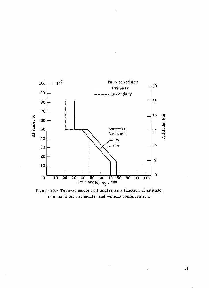
£•I
0)T3.2<~4
100
90
80
70
60
50
40
30
20
10
v 1fl3 Turn schedule :~ Pf- Qt- ~I3°
~ Secondary
II
I- II
L
—
—
X IX ~~~"V\ fuel tank
XX ^OnI \\ /^\ VVVoffi XXI \\\\ -I I III I I I I I I I I I
25
20
15
10
5
0
£•^oT2i— (
^
10 20 30 40 50 60 70 80 90 100 110Roll angle, 4>c , deg
Figure 25.- Turn-schedule roll angles as a function of altitude,command turn schedule, and vehicle configuration.
51

§o>N
OS(M0in• •
coON
oo<MOin
O (M
(M0
00• •t-
ONN• •
t-<M .n
CDin No
o<D
I I I I I I I I I I I I I I IIft o
r-lI
o mN N
TH O
J
O
s sS -
^ SfcJD
NO £N fe* •
•*O N.-14f<No
O
•ONinCONON
0O
Oin• •
o
Sap 'Sap 'o
jos^tun S
COt-,cu>3
Q.
0.
«COCO
•ooo
-(->CO0)
.a>
0)tl
En
52

40 i-
30
oCOco00
c'to
a
20
10
O
Based on CT for a rigid aircraft (untrimmed)a
10 20 30
. kN
40 50
Figure 27.- Comparison of normal forces based on CL for a rigid aircraft.
53

40 r-
30
ooocoooC35
I
20
10
O
Based on CT for an elasticLa
aircraft, untrimmed
10 20 30 40
Figure 28.- Comparison of normal forces based on Cf for an'-'a
untrimmed elastic aircraft.
54

Based on C? for an elastic aircraft, trimmed
10 20, e i.. .. \ i . ,T2C
30
a( « - o o ) P V 2 S , k No
Figure 29.- Comparison of normal forces based on C
trimmed elastic aircraft.
40
for a
NASA-Langley, 1975 L-10333 55

NATIONAL AERONAUTICS AND SPACE ADMINISTRATION
WASHINGTON, D.C. 2O546
OFFICIAL BUSINESS
PENALTY FOR PRIVATE USE S3OO SPECIAL FOURTH-CLASS RATEBOOK
POSTAGE AND FEES PAIDNATIONAL AERONAUTICS AND
SPACE ADMINISTRATION451
POSTMASTER : If Undeliverable (Section 158Postal Manual) Do Not Return
"The aeronautical and space activities of the United States shall beconducted so as to contribute . . . to the expansion of human knowl-edge of phenomena in the atmosphere and space. The Administrationshall provide for the widest practicable and appropriate disseminationof information concerning its activities and the results thereof."
—NATIONAL AERONAUTICS AND SPACE ACT OF 1958
NASA SCIENTIFIC AND TECHNICAL PUBLICATIONSTECHNICAL REPORTS: Scientific andtechnical information considered important,complete, and a lasting contribution to existingknowledge.
TECHNICAL NOTES: Information less broadin scope but nevertheless of importance as acontribution to existing knowledge.
TECHNICAL MEMORANDUMS:Information receiving limited distributionbecause of preliminary data, security classifica-tion, or other reasons. Also includes conferenceproceedings with either limited or unlimiteddistribution.
CONTRACTOR REPORTS: Scientific andtechnical information generated under a NASAcontract or grant and considered an importantcontribution to existing knowledge.
TECHNICAL TRANSLATIONS: Informationpublished in a foreign language consideredto merit NASA distribution in English.
SPECIAL PUBLICATIONS: Informationderived from or of value to NASA activities.Publications include final reports of majorprojects, monographs, data compilations,handbooks, sourcebooks, and specialbibliographies.
TECHNOLOGY UTILIZATIONPUBLICATIONS: Information on technologyused by NASA that may be of particularinterest in commercial and other non-aerospaceapplications. Publications include Tech Briefs,Technology Utilization Reports andTechnology Surveys.
Details on the availability of these publications may be obtained from:
SCIENTIFIC AND TECHNICAL INFORMATION OFFICE
N A T I O N A L A E R O N A U T I C S A N D S P A C E A D M I N I S T R A T I O NWashington, D.C. 20546