Flexural Strength of Prestressed Concrete Sections by ...
23
Flexural Strength of Prestressed Concrete Sections by Programmable Calculator Alan H. Mattock Professor of Civil Engineering University of Washington Seattle, Washington ' t has always been recognized that the approximate Eq. (18-3) in ACI 318-77' for the stress in bonded pre- stressing steel at flexural ultimate, f,,, was in general conservative. A more precise value for f, and hence for the flexural strength, can be obtained by solving the equations of equilibrium of forces and of compatibility of strains across the section, making use of the actual stress-strain relationship for the prestressing steel. Until the advent of the computer and the pro- grammable calculator, this was a time-consuming process and hence was little used. In a 1977 paper, Naaman 2 discussed the more precise approach. He showed how more accurate values of flexural strength could readily be ob- tained using a computer to solve the equations of equilibrium and com- patibility, if the stress-strain curve for the prestressing steel were expressed algebraically. Since the time of Naaman's studies, there has been an explosion in the availability and the capabilities of small programmable electronic cal- culators. These machines now make it feasible and economic for any en- gineer to use the more precise method of calculation for flexural strength, with consequent economic advan- tages. Prestressing Steel, Stress-Strain Curve The stress-strain curve for pre- stressing steel typically consists of a linear part (corresponding to the re- gion of elastic behavior), a sharply curved part in the vicinity of the nominal yield point stress, and an al- 32
Transcript of Flexural Strength of Prestressed Concrete Sections by ...

Flexural Strength ofPrestressed Concrete Sectionsby Programmable Calculator
Alan H. MattockProfessor of Civil EngineeringUniversity of WashingtonSeattle, Washington
't has always been recognized thatthe approximate Eq. (18-3) in ACI
318-77' for the stress in bonded pre-stressing steel at flexural ultimate, f,,,was in general conservative. A moreprecise value for f, and hence for theflexural strength, can be obtained bysolving the equations of equilibriumof forces and of compatibility ofstrains across the section, making useof the actual stress-strain relationshipfor the prestressing steel. Until theadvent of the computer and the pro-grammable calculator, this was atime-consuming process and hencewas little used.
In a 1977 paper, Naaman2 discussedthe more precise approach. Heshowed how more accurate values offlexural strength could readily be ob-tained using a computer to solve theequations of equilibrium and com-patibility, if the stress-strain curve for
the prestressing steel were expressedalgebraically.
Since the time of Naaman's studies,there has been an explosion in theavailability and the capabilities ofsmall programmable electronic cal-culators. These machines now make itfeasible and economic for any en-gineer to use the more precise methodof calculation for flexural strength,with consequent economic advan-tages.
Prestressing Steel,Stress-Strain Curve
The stress-strain curve for pre-stressing steel typically consists of alinear part (corresponding to the re-gion of elastic behavior), a sharplycurved part in the vicinity of thenominal yield point stress, and an al-
32
2 3 4E* = E/Ea
Fig. 1. Curve corresponding to Eq. (1).
0
most linear, slightly strain-hardeningpart reaching to failure.
Naaman represented the stress-strain curve by three separate equa-tions, corresponding to the three partsof the curve identified above. He usedtwo different linear equations for thefirst and third parts, and a fourth de-gree polynomial for strains between0.006 and 0.014. The eight coefficientsof these equations were determinedusing the computer, so as to give thebest fit.
This approach to algebraic repre-sentation of the steel stress-straincurve does not lend itself to use with asmall calculator. Other possibilitieswere therefore investigated.
It has been found possible to rep-resent the stress-strain curve of pre-stressing steel very closely using a'single equation of the form:
fs = ( I — Q) E x ) + QE* (1)1/R(I +E
where fs = fs/fso and E * = E /Eo
In the above, fS is the stress at astrain E, f8° and E a are a referencestress and its corresponding strain.
This form of equation was used byMenegotto and Pinto 3 to represent the
stress-strain relationship for reinforc-ing bars subjected to cyclic loadingbeyond their yield point. The curverepresented by Eq. (1) is shown inFig. 1. The first part of the curve islinear with a slope of unity; the sec-ond part is curved, the radius of cur-vature becoming larger as the coeffi-cientR decreases; and the third part islinear with a slope equal to the coeffi-cientQ.
This form of curve has been adaptedto represent the stress-strain curve ofprestressing steel by making:
fso = Kf and E. = KfpylE
PCI JOURNAL/January-February 1979 33

fs
K fpy
0.01 E CPU
Fig. 2. Typical stress -strain curve forprestressing steel as representedby Eq. (2).
whereK = a coefficient
f= specified yield strength ofprestressing steel
E = modulus of elasticity of pre-stressing steel
The equation then becomes:
f =EE Q+ ( 1–Q \
j1+(
€ERl1JRKf^ l J J (2)
where
Q= (fzu –K.f1,EPUE - K.ff3,
The coefficient R is determined bysolving Eq. (2) for the conditionfg = fp, when E = 0.010. The values f„uand E pu are the specified tensilestrength and the strain at tensile fail-ure of the prestressing steel, respec-tively.
The curve corresponding to Eq. (2)is shown in Fig. 2. The initial slope isequal to the modulus of elasticity, thecurve passes through the nominalyield point and the final slope corre-sponds to the measured strain-hard-ening behavior of the steel.
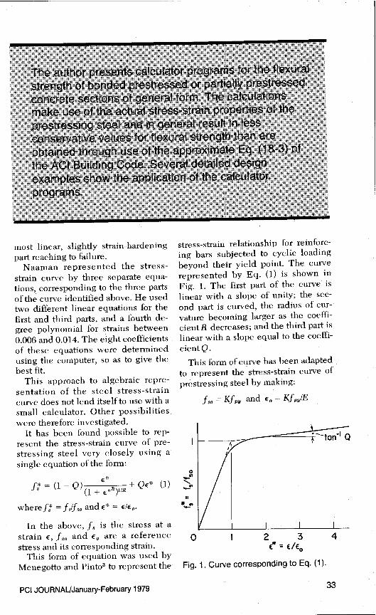
Eq. (2) can be made to correspondvery closely to actual stress-strain
curves, as shown in Fig. 3, by use ofappropriate values for the coefficientsK, Q, and R. Using Eq. (2) it has beenfound possible to calculate the stresscorresponding to a given strain towithin 1 percent or less, for a numberof actual stress-strain curves.
If the complete stress-strain curvefor the steel is available, K is deter-mined as follows:
Produce the two linear parts of thestress-strain curves until they meet.The stress corresponding to the pointof intersection is Kf. Hence, obtainK. If the complete steel stress-straincurve is not available, a reasonablevalue to assume for K in the case ofseven-wire strand is 1.04.
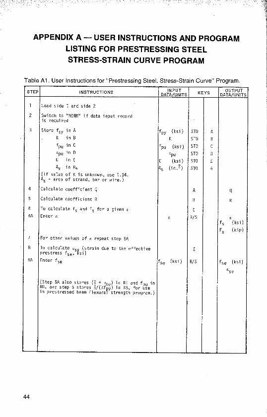
In Appendix A are given the userinstructions and the listing of a pro-gram for the Hewlett Packard HP-67/97 programmable calculators,which will:
1. Determine the values of Q and Rfor the stress-strain curve for aparticular steel, given fps, f , E,
and K.2. Calculate the stress and the force
in a tendon of cross section A8,for any given strain E. (Agree-ment between the calculated andexperimental stress-strain re-lationships can therefore bechecked readily.)
3. Calculate the strain E 8e corre-sponding to the effective pre-stress fSe in a particular pre-stressed beam, and store asneeded for a subsequent flexuralstrength calculation.
The solution of Eq. (2) to obtain R iscarried out using an adaptation ofNewton's method. 4 This involves aniterative procedure and typically takesabout 45 seconds. For this program towork, Kf must be less than f,. andgreater than about 0.75 fem . This cov-ers the characteristics of prestressingsteels meeting the relevant ASTMspecifications.
34
P•e
Calculated values, (4 = 1.06,Q=0.0105, R= 7.447)
Seven wire strand stress-strain curve,200 (f 274.0 ksi, fpy= 239.2 ksi)
N
Calculated values, (K=1.02,Q=0.0043, R 4.190)
100 1%8 in. 0 prestressing bar stress-strain curve,( f= 156.6 ksi, fpy = 148.0 ksi)
0 0.01 0.02 0.03 0.04 0.05 0.06 0.07 0.08Strain , e
Fig. 3. Comparison of calculated values off s and a with experimental stress-strain curves.
equations developed and the cal-Calculation of culator program based on them are
Flexural Strength
applicable to a variety of beam sec-tions, as shown later.
The calculation of flexural strength Use is made of the equivalent rec-is based on Section 10.2—Design As- tangular stress distribution defined insumptions, of ACI 318-77; except that Section 10.2.7 of ACI 318-77 whenthe stress in the reinforcement is as- calculating the resultant compressionsumed to be related to the strain in force in the concrete at ultimate, andaccordance with Eq. (2) above. Both its center of action.* The width of thethe prestressed and the non-pre- section at the bottom edge of thestressed reinforcement is assumed to equivalent rectangular stress distribu-have the same stress-strain curve. tion is designated as b', i.e., at dis-Such a situation arises when seven- tance "a" from the maximum com-wire strand is used as both prestressed pression fiber.and non-prestressed reinforcement. The resultant concrete compression
The stress and strain conditions in a force C for various possible locations
bonded prestressed concrete beam are of the neutral axis is given by:shown in Fig. 4. A single-tee sectionwith a tapering flange and fillets at the
The applicability of the equivalent rectangular stressdistribution to non-rectangular sections has been ver-
web-flange junction is shown, but the iaedexperirnentallY5•s
PCI JOURNAUJanuary-February 1979 35

B t t 0.003
b }^̂ - r_ 7 tz
a At
dP I Ultimated bw At ^^y
• • Prestress Ii
• • Aps ecp I EI
A8
0.85f
c C ac
C
Aps.fp= APVf
A..fe A5. f5
Cross- Section Concrete Actual AssumedStrains Stresses at Ultimate
Fig. 4. Stress and strain conditions in a prestressed single-tee.
(a) a _- t; C = 0.85 ff Ba (3)
(b) t<a<t 1 ; C=0.85f4Ai+(a–t {B– ()(t)] (4)2 tl—t
(c) tr <a< tz; C = 0.85ff Az + (a – tr)j` b –
a– l-t(b bw
(5)l / \ t2—tl l
(d) t 2 < a; C = 0.85 f4A 3 + (a – t2 )b w1 (6)
whereA 1 = Bt andA 2 = A 1 +^B + b^
(tl–t)2
andA3=A2+ (b+bw)(tt)
Since the reinforcement is bondedto the concrete, the change in strain inthe reinforcement can be assumedequal to the change in strain in theadjacent concrete. The strain in theprestressed reinforcement at flexuralultimate e,,, is therefore given by:
E py = E Se + E cp + E1
E ps = E Se + E cp + 0.003(dp — c) /C (7where
E Se = strain in reinforcementA 13 dueto effective prestress fSe
andE Cp = compressive strain in concrete
adjacent to A„ 8 , due to pre-stress
The strain E,p is very small com-pared to E3e and E 1i and for simplicitymay be neglected. Hence we maywrite:
E ps = E 8e + 0.003(d p – c)IC (8)
The strain in the unprestressedreinforcement at flexural ultimate Es,
is given by:
e S = 0.003(d – c)/c (9;
The stresses f1, and f3 in the pre-stressed and unprestressed reinforce-ment at flexural ultimate, can be ob-tained by substituting the strains EP8
and E g in Eq. (2). The total tensile
36
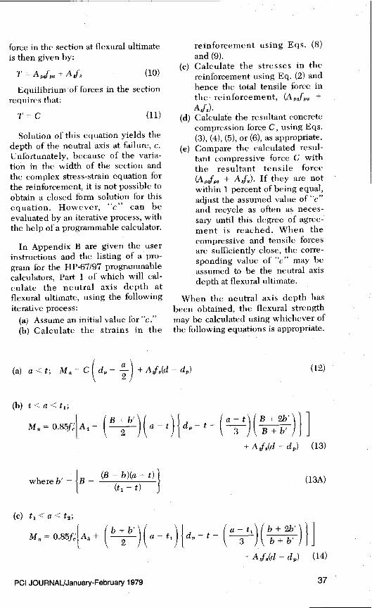
force in the section at flexural ultimateis then given by:
T = Ajj8 +A/B (10)
Equilibrium of forces in the sectionrequires that:
T=C (11)
Solution of this equation yields thedepth of the neutral axis at failure, c.Unfortunately, because of the varia-tion in the width of the section andthe complex stress-strain equation forthe reinforcement, it is not possible toobtain a closed form solution for thisequation. However, "c" can beevaluated by an iterative process, withthe help of a programmable calculator.
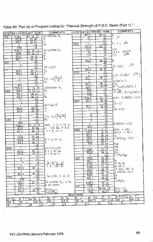
In Appendix B are given the userinstructions and the listing of a pro-gram for the HP-67/97 programmablecalculators, Part 1 of which will cal-culate the neutral axis depth atflexural ultimate, using the followingiterative process:
(a) Assume an initial value for "c."(b) Calculate the strains in the
reinforcement using Eqs. (8)and (9).
(c) Calculate the stresses in thereinforcement using Eq. (2) andhence the total tensile force inthe reinforcement, (A PJ 3 +
Asf3)•(d) Calculate the resultant concrete
compression force C, using Eqs.(3), (4), (5), or (6), as appropriate.
(e) Compare the calculated resul-tant compressive force C- withthe resultant tensile force(A p$f 3 + A J, ). If they are notwithin 1 percent of being equal,adjust the assumed value of "c"and recycle as often as neces-sary until this degree of agree-ment is reached. When thecompressive and tensile forcesare sufficiently close, the corre-sponding value of "c" may beassumed to be the neutral axisdepth at flexural ultimate.
When the neutral axis depth hasbeen obtained, the flexural strengthmay be calculated using whichever ofthe following equations is appropriate.
(a) a<t; M.=C(dp— 2)+Ae8(d_d)
(12)
(b) t < a < t,;
M„= 0.85f [A 4+
(B+b \f
2 l\ a - t l^ d-- t– \ a 3 t l\ B+ b l^ J
+ A sf8(d – d p) (13)
where b' = {B – (B – b)(a – t)
l (t 1 – t) (13A)
(c) t, < a < t2;
M n = 0.85f^LA 5 + I b 2 b )(a_ti)d–t
\ a 3t1/( b+b' )I]+ A /8(d – d,,) (14)
PCI JOURNAL/January-February 1979 37

1 f`_ 8 I b B bt I r B -'1 t t'
- t
h b" _hJ ^f wr—
Jblf JbL(a) (b) w (c) w (d)
Br`
h,(e) h J
Lb
b-1 t rb ti-1 hi
(f) w bw
—B —I
(g) -- -i
Dimension to be Entered
b) T- (c)Dbl-Tee (d) I(I)
(e)lnv: Tee (f) Box A^^ (g) Box(2)Vit B B B B B B
b w 2b* bw b 2b (B-0.3D)b 2bw bw b 2bw (B-D)3H t h t t t hi t (h1-O.5D)
3J ti t t ti h^ t (h i - 0.5D)3K t2 h h h^ h ti (h1-0.2D)
No entry (I) a) h 1 (2) Very nearly , a 1 I.2 hi
Fig. 5. Use of program for various sections.
where b' _ Jb — (b — b.W )(a — tl) J (14A)
(t2-ti)
(d) t2 < a;
M n = 0.85f^1 A 6 + (a — t2)(bw)fdp — (t2 2 a) } ] + A/g(d — d
P) (15)
where A 4 = L (Bt)(d,, — t/2) (16)
A 5 =A4 + ^ B 2b l^t1—t)jd,—t— (t^
3 t)(B+b)1 (17)
A 6 =A5+ (b±bw)(tt){dt ( t2t1)()} (18)
38

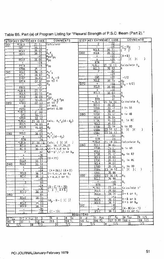
Part 2 of the calculator programgiven in Appendix B calculates thenominal flexural strength M. and thedesign flexural strength OM,,, usingwhichever of the above equations isappropriate. The program also printsout the reinforcement stresses atflexural ultimate and indicateswhether the prestressed reinforce-ment has yielded. This corresponds tochecking whether (o , (w + wP) or
(w,,, + w) is less than 0.30, as re-quired by ACI 318-77.
Although the program was writteninitially for the single-tee sectionshown in Fig. 4, it can also be used fora variety of other sections, such asthose shown in Fig. 5. All that isnecessary is to make the substitutionsshown in Fig. 5 when entering thesection dimensions in User Instruc-tion Steps 3E through 3K (Table B1).
Examples of Use of the Programs
In the following examples, the calculator "print out" is shown initalics.
Example 1Calculate the coefficients of the stress-strain curve equation, and E Se cor-
responding to fse = 160 ksi, given:= 270 ksi f,, = 240 ksi
K = 1.04 E = 28,000 ksiE,.. = 0.05 A$ = 0.153 in. 2 ( 1/2-in. (P strand)
1. Load "Prestressing Steel, Stress-Strain Curve" program.2. Switch at "MAN,"—No input data record.3. Store data using keystrokes:
240 STO[]A , STO ®, 270 STO ® ,
0.05 EiIO U , 28,000 E1J®, 0.153 1I .4. Press ® —p 0.0177 (coefficientQ)
5. Press ® — 7.9694 (coefficientR)
6. Check stress at E = 0.01 (i.e., fp ), using keystrokes
© 0.01 ®-0.0100 . (E)
240.0 (fg, ksi) O.K.36.72 (F 8 , kip)
7. For any other strain "E," use keystrokes:
E I2S — E
fS (ksi)F 8 (kip)
8. Calculate E for f^ = 160 ksi, using keystrokes:
qE 160 I7I1 — 160.0 (f^, ksi)
0.0057 (ESe)
PCI JOURNAL/January-February 1979 39
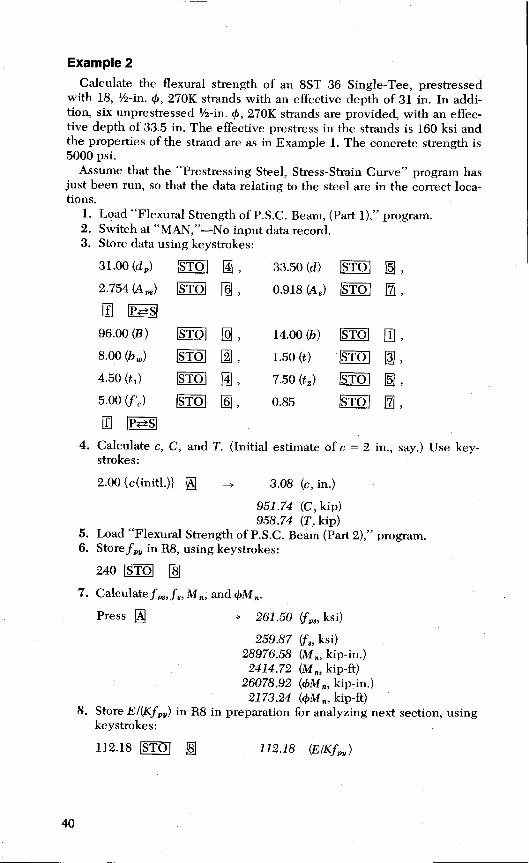
Example 2Calculate the flexural strength of an 8ST 36 Single-Tee, prestressed
with 18, ½-in. 0, 270K strands with an effective depth of 31 in. In addi-tion, six unprestressed' -in. 0, 270K strands are provided, with an effec-tive depth of 33.5 in. The effective prestress in the strands is 160 ksi andthe properties of the strand are as in Example 1. The concrete strength is5000 psi.
Assume that the "Prestressing Steel, Stress-Strain Curve" program hasjust been run, so that the data relating to the steel are in the correct loca-tions.
1. Load "Flexural Strength of P.S.C. Beam, (Part 1)," program.2. Switch at "MAN,"-No input data record.3. Store data using keystrokes:
31.00 (dr) Ej ® , 33.50 (d) STO []5 ,
2.754 (A m) E1I©, 0.918 (A $) EJJ 07 ,qf PAS
96.00 (B) , 14.00 (b) STO [1 ,8.00 (b)STO []2 , 1.50 (t) IIJ!J,4.50 (t 1 ) STO ®, 7.50 (t 2 ) ,
5.00 (f'c ) STO ©, 0.85 tJ 07 ,
qf PES
4. Calculate c, C, and T. (Initial estimate of c = 2 in., say.) Use key-strokes:
2.00 {c(initl.)} ® -* 3.08 (c, in.)
951.74 (C, kip)958.74 (T, kip)
5. Load "Flexural Strength of P.S.C. Beam (Part 2)," program.6. Store f ,, in R8, using keystrokes:
240 STO
7. Calculate f ,3 , f8 , M., and 4)M..
Press ® - 261.50 (fz,,, ksi)
259.87 (f$, ksi)28976.58 (M R , kip-in.)2414.72 (M„, kip-ft)
26078.92 (4)M, kip-in.)2173.24 (4)M,,, kip-ft)
8. Store E/(Kff,) in R8 in preparation for analyzing next section, usingkeystrokes:
112.18 fJ ® 112.18 (ElKfp^ )
40
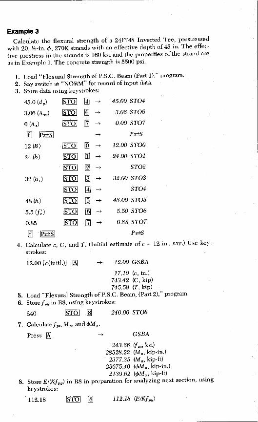
Example 3Calculate the flexural strength of a 24IT48 Inverted Tee, prestressed
with 20, 1/2-in. 0, 270K strands with an effective depth of 45 in. The effec-tive prestress in the strands is 160 ksi and the properties of the strand areas in Example 1. The concrete strength is 5500 psi.
1. Load "Flcxural Strength of P.S.C. Beam (Part 1)," program.2. Say switch at "NORM" for record of input data.3. Store data using keystrokes:
45.0 (d r) Ii1 ® , 45.00 STO4
3.06 (A,) STO © , 3.06 STO6
0(A8) - 0.00 STO7
Iii S - P #S
12 (B) STO - 12.00 STOO
24 (b) STO j1 24.00 STO1
STO [2 STO2
32(h 1 ) STO 03 - 32.00 STO3
STO ® -+ STO4
48 (h) STO n5 - 48.00 STO5
5.5 (f,) STO © -+ 5.50 ST06
0.85 []7 - 0.85 STO7
1S PAS
4. Calculate c, C, and T. (Initial estimate of c = 12 in., say.) Use key-strokes:
12.00 {c(initl.)} ® -^ 12.00 GSBA
17.10 (c, in.)743.42 (C, kip)745.59 (T, kip)
5. Load"Flexural Strength of P.S.C. Beam, (Part 2)," program.6. Store fr,, in R8, using keystrokes:
240 STO ® 240.00 STO8
7. Calculate fp8 , M., and (AM.
Press ® -+ GSBA
243.66 f98 , ksi)28528.22 (M., kip-in.)
2377.35 (M., kip-ft)25675.40 (4)M n,, kip-in.)
2139.62 (4)M,z , kip-ft)8. Store El(Kfp81 ) in R8 in preparation for analyzing next section, using
keystrokes:
112.18 STO ® 112.18 (ElKfpy)

Example 4Calculate the flexural strength of an 8DT32B Double Tee, prestressed
with 28, '/2-in. 0, 270K strands with an effective depth of 28.5 in. Theeffective prestress in the strands is 160 ksi and the properties of the strandare as in Example 1. The concrete strength is 6000 psi.
1. Load "Flexural Strength of P.S.C. Beam (Part 1)," program.2. Say switch at "NORM" for record of input data.3. Store data using keystrokes:
28.5 (d9 ) 1IjJ ® , 28.50 STO4
4.28 (A P,) STO © -* 4.28 STO6
0(A 3 ) -3 0.00 STO7
O J PAS
96 (B) STO ® -^ 96.00 STOO
19.50 (2b,) Lijj []1 - 19.50 STO1
12.00 (2h) STO © -* 12.00 STO2
2.00 (t) fIi1 [3i - 2.00 STO3
STO ® - STO4
32.00 (h) E1O []5 - 32.00 STO5
6.00(f) EiIJ ® - 6.00 STO6
0.85 []7 - 0.85 STO7
qf PES PAS4. Calculate c, C, and T. (Initial estimate of c = 3 in., say.) Use key-
strokes:
3.00 {c(initl.)} 3.00 GSBA
4.14 (c, in.)1088.66 (C, kip)1098.88 (T, kip)
5. Load "Flexural Strength of P.S.C. Beam, (Part 2)," program:6. Store f 1, in R8, using keystrokes:
240 fiIJ® 240.00 STO8
7. Calculate f,,3, M,,, and OM,
Press ® GSBA
256.75 (f„g, ksi)29768.16 (Ma, kip-in.)2480.68 (M a, kip-ft)
26791.35 (4,M,,, kip-in.)2232.61 (4M n, kip-ft)
42
Concluding RemarksCalculator programs for determining
the flexural strength of bonded pre-stressed concrete beams, and theequations on which they are based,have been presented. The programsare applicable to most beam crosssections in current use. They makeuse of the actual stress-strain curve ofthe prestressing steel and hence inmany cases yield a less conservativevalue of flexural strength than is ob-tained when use is made of Eq. (18-3)of ACI 318-77. Although the programsapply specifically to the HewlettPackard, HP-67/97 calculators, theycould readily be adapted to othertypes of programmable calculators.
References
1. ACI Committee 318, "Building CodeRequirements for Reinforced Concrete(ACI 318-77)," American Concrete In-stitute, Detroit, Michigan, 1977, P. 70.
2. Naaman, A. E., "Ultimate Analysis ofPrestressed and Partially PrestressedSections by Strain Compatibility," PCIJOURNAL, V. 22, No. 1, January-Feb-ruary 1977, pp. 32-51..
3. Menegotto, M., and Pinto, P. E.,"Method of Analysis for CyclicallyLoaded R.C. Plane Frames, IncludingChanges in Geometry and Non-ElasticBehavior of Elements Under CombinedNormal Force and Bending," Interna-tional Association for Bridge andStructural Engineering, PreliminaryReport for Symposium on Resistanceand Ultimate Deformability of Struc-tures Acted on by Well-Defined Re-peated Loads, Lisbon, 1973, pp. 15-22.
4. Wheeler, W., "Fast Programming onSmall Calculators," Civil Engineering-ASCE, April 1977, pp. 58-60.
5. Mattock, A. H., and Kriz, L. B., "Ulti-mate Strength of Structural ConcreteMembers with Nonrectangular Com-pression Zones," ACI Journal, Pro-ceedings V. 57, No. 7, January 1961, pp.737-766.
6. Mattock, A. H., Kriz, L. B., and Hog-nestad, E., "Rectangular ConcreteStress Distribution in Ultimate StrengthDesign," ACI Journal, Proceedings V.57, No. 8, February 1961, pp. 875-928.
PCI JOURNAUJanuary-February 1979 43


APPENDIX C-SUMMARY OF FEATURESOF THE HP67/97 CALCULATORS
The Hewlett Packard 67/97 cal-culators employ Reverse Polish Nota-tion. They have 16 primary (direct)storage registers 0 through 9, Athrough E and I, as well as 10 secon-dary registers which are exchangedwith the primary registers 0 through 9by use of the P > S key.
Conditional tests such as X % Y? orX < Y? execute the next step in mem-ory if the conditional expression istrue, or skip one step before resumingexecution if the conditional is false.
Other special functions which areavailable on other calculators or mayeasily be implemented are the fol-lowing:
R/S Run/Stop. Stops programexecution for data entry.When key is pressed, be-gins execution from currentstep in program.
LBLA Defines beginning of aroutine (here labeled A).When label key (i.e., A inthis example) is pressed,execution of program com-mences at this step.
GTOA Causes calculator to stopexecution and searchdownwards through pro-gram to first designated
label, and resume executionthere, (i.e., directs branch-ing of program).
GSBA As GTOA, but at end ofsubroutine control is re-turned to next step afterGSBA.
RTN If at end of subroutine, re-turns control to next stepafter GSB instruction;otherwise stops executionand returns control tokeyboard.
ST– 3 Subtracts the current valuefrom memory register 3 andthe result is stored in mem-ory 3. Likewise, ST + 9would add current value tomemory register 9.
DSP4 Fixes the display so that 4digits are displayed to rightof decimal point.
FRC Obtains fractional part of anumber.
CHS Changes sign of currentvalue.
PRTX Prints the current value.SPC Advances the print paper
one space.The above summary is provided to
assist in the translation of the pro-grams given in this paper to a formsuitable for other calculators.
PCI JOURNAL/January-February 1979 53

APPENDIX D-NOTATION
a = depth of equivalent rectangu-lar stress block as defined inSection 10.2.7 of ACI 318-77,'in.
AP, = area of prestressed tensionreinforcement, in.2
A, = area of non-prestressed tensionreinforcement, in.2
b = width of section at top of fillet(see Fig. 4), in.
b' = width of section at distance"a" from extreme compressionfiber, in.
bw = width of web or stem of sec-tion, in.
B = width of flange at extremecompression fiber, in.
C = distance from extreme compression fiber to neutral axis,in.
C = resultant concrete compressionforce, kips
d = distance from extreme com-pression fiber to centroid ofunprestressed tension rein-forcement, in.
d, = distance from extreme com-pression fiber to centroid ofprestressed tension reinforce-ment, in.
E = modulus of elasticity of rein-forcement, ksi
f, = compressive strength of con-crete (measured on 6 x 12-in.cylinders), ksi
fps = stress in prestressed rein-forcement at nominal strength,ksi
fnu = specified tensile strength ofprestressing steel, ksi
J py = specified yield strength of pre-stressing steel, ksi
J s = stress in unprestressed rein-forcement at nominal strength,ksi or, stress in reinforcementat strain c
J8 = fl/f80fse = effective prestress in pre-
stressed reinforcement, ksifso = a reference stress (see Fig. 1)
54
F, = force in a single strand at strainE, kips
K = a coefficientM„ = nominal flexural strength of
section, in.-lb or ft-lb
Q = CPU – Kf9.) /(E PUE – Kf95)R = a coefficientt = thickness of uniform width
part of flange (see Fig. 4)t l = depth to top of fillets (see Fig.
4)t 2 = depth to bottom of fillets (see
Fig. 4)T = resultant tensile force in rein-
forcement, kips/3 1 = a/c, factor defined in Section
10.2.7 of ACI 318-77E = strainE* = E/Eo
E o = a reference strain (see Fig. 1)E 1 = change in strain in prestressed
reinforcement due to loadingto nominal flexural strength
E, = strain in concrete at level ofprestressed reinforcement dueto prestress
E p, = strain in prestressed rein-forcement at nominal flexuralstrength
E S = strain in unprestressed rein-forcement at nominal flexuralstrength
E se = strain in prestressed rein-forcement due to effective pre-stress f8Q
E. = strain in prestressing steel atstress f9u
= strength reduction factor as perChapter 9 of ACI 318-77
= (A3/Bd)fb /f,'W p = (A,9/Bd)f93(fe
COw
= reinforcement indices forflanged sections computed asfor w and co p, except replace Bby b w, and reinforcement areais that required to developcompressive strength of theweb only.