FLEXOP: Integrated Modelling Approach for Flexible … · · 2017-10-24• Unsteady Aerodynamics:...
41
> Flexop > Integrated Flexible Aircraft Modelling > T.Kier > DLR-SR > 19.09.2017 DLR.de • Chart 1 FLEXOP: Integrated Modelling Approach for Flexible Aircraft Dynamics International Workshop on Robust Modelling, Design & Analysis 18 th and 19 th September 2017, Bristol, UK Thiemo Kier Manuel Pusch, Matthias Wüstenhagen, Martin Leitner DLR Oberpfaffenhofen Institute of System Dynamics & Control
Transcript of FLEXOP: Integrated Modelling Approach for Flexible … · · 2017-10-24• Unsteady Aerodynamics:...

> Flexop > Integrated Flexible Aircraft Modelling > T.Kier > DLR-SR > 19.09.2017DLR.de • Chart 1
FLEXOP: Integrated Modelling Approach for Flexible Aircraft DynamicsInternational Workshop on Robust Modelling, Design & Analysis18th and 19th September 2017, Bristol, UK
Thiemo Kier Manuel Pusch, Matthias Wüstenhagen, Martin Leitner
DLR OberpfaffenhofenInstitute of System Dynamics & Control

Overview
> Flexop > Integrated Flexible Aircraft Modelling > T.Kier > DLR-SR > 19.09.2017DLR.de • Chart 2
Aeroelastic model integration:
• Aeroelastic Model Building: The Aero-Servo-Elastic Tetrahedron
• Dynamic Aircraft Model Integration Process: DAMIP
• FEM concepts: Stiffness Model, Guyan reduction, Modal Analysis, EOM
• Aerodynamics: Potential Flow, Vortex Lattice Method, Aerodynamic InfluenceCoefficients, boundary conditions
• Unsteady Aerodynamics: Kelvin Thompson Theorem, Wagner Function, DoubletLattice Method, Rational Function Approximation
FLEXOP:
• Data sources and Preprocessing steps for the FLEXOP demonstrator
• Flutter Analysis Methods: PK, P and Eigenvalues of the integrated model
• Mass Sensitivity of Flutter Results
• CFD corrected AICs and interpolation of nonlinear effects
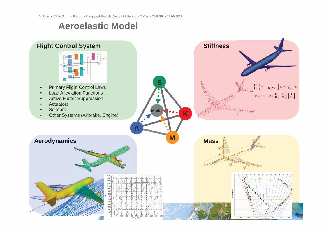
Aeroelastic Model
Model
AM
S
K
Aerodynamics Mass
StiffnessFlight Control System
Aerodynamicss
Stiffness
• Primary Flight Control Laws• Load Alleviation Functions• Active Flutter Suppression• Actuators• Sensors• Other Systems (Airbrake, Engine)
> Flexop > Integrated Flexible Aircraft Modelling > T.Kier > DLR-SR > 19.09.2017DLR.de • Chart 3

Different Models with Different Requirements forDifferent Purposes (but based on the same Data)
• Flight Mechanics• Control Design for Primary flight control laws (Baseline Controller)• Real time capable model for pilot training
• Structural Dynamics / Flutter / Loads• Flutter Analysis• Control Design for Active Flutter Suppression• Loads Analysis• Control Design for Loads Alleviation
• Hardware in the Loop Simulations• Seperate (Sub-)Models for each component (e.g. aero forces for test
bed)
• Validation Models• Not necessarily real time capable• Include „everything“ in nonlinear ODE based model
> Flexop > Integrated Flexible Aircraft Modelling > T.Kier > DLR-SR > 19.09.2017DLR.de • Chart 4

DLR Dynamic Aircraft Model Integration Process
Data Sourcesaircraft geometry
Aerodynamic databases
CFD data
Mass, weight & balance
Stiffness model
Systems architecture
Model IntegrationSelection of modelequations:
Nonlinear modelequations
Linear, frequency domainequations
Linear state space models
PreprocessingModal analysis
Potential Flow Aero (AICs)
Rational function approx.
Data correction, inter-polation and transformation
Selection of environmental model
Model ApplicationLoads Analysis
Flutter Analysis
Flight Dyn. Simulation
Flight control law design
Real-time Simulation
Model Implementation
Object-Oriented (Modelica)
Block Diagram (Simulink)
Software Algorithms (Fortran, Matlab)
> Flexop > Integrated Flexible Aircraft Modelling > T.Kier > DLR-SR > 19.09.2017DLR.de • Chart 5

> Flexop > Integrated Flexible Aircraft Modelling > T.Kier > DLR-SR > 19.09.2017
Partitioning the System Matrices (reference nodes remain in a-set):Assume no load on omitted grid points:
Neglecting inertial terms, yields the following transfromation:
This results in the overall reduced stiffness matrix, where we apply theaeroloads and put the masses
Stiffness and Mass Model PreparationGuyan Reduction
1. Global FEM Assembly
2. Static condensation to Condensation points on Load Reference Axes Kgg
3. Lump structural and nonstructural masses (OWE + Payload + Fuel) to those grid points Mgg
4. Kgg and Mgg are used for modal analysis
5. Rigidly connect rib end points for splining of Aero
6. Cut Load Integration points (between condensationpoints)
DLR.de • Chart 6

Normal Modes Analysis
> Flexop > Integrated Flexible Aircraft Modelling > T.Kier > DLR-SR > 19.09.2017DLR.de • Chart 7
Equation of motion:
Generalized Eigenvalue Problem:
Eigenvalues and Eigenvectors:
Generalized Mass and Stiffness:
Modeshapes and frequenciesare then compared to GVT data

Equations of Motion
• Linear (frequency domain)
• Non-linear (time domain)
• External Loads mainly from Propulsion and Aerodynamics
> Flexop > Integrated Flexible Aircraft Modelling > T.Kier > DLR-SR > 19.09.2017DLR.de • Chart 8

Aerodynamic Governing Equations
inviscid
Navier-StokesConservation of mass
momentum energy
Euler
Full Potential
irrotationalisentropic
cancel time derivatives
Prandtl Glauert
Laplace
Strip Theorystripwise multiplication with an empirical gradient coefficient
empirical
linearizedLinear Methods
Doublet Lattice Method(unsteady)Mean Lifting Surface Grid
Vortex Lattice Method(steady)Mean Lifting Surface Grid
3D Panel Methods(steady, unsteady)Surface Grid
Note: Steady Compressibility accountedfor by Prandtl – Glauert –GöthertTransformation
no boundary layerno turbulence
no strong shocks
no transonic effects
NonlinearMethods
Finite DifferenceFinite Volume Finite ElementVolume Grid
also:Field Panel MethodSurface grid + cartesianfield overset
steady compr. ORunsteady incompr.
no interactionSmall y and z disturbances no blunt bodies
TSD
> Flexop > Integrated Flexible Aircraft Modelling > T.Kier > DLR-SR > 19.09.2017DLR.de • Chart 9

• Linear relationship between local angle of attack at the control point and thesurface pressure distribution
• Accounting for roll/yaw/pitch rate as well as structural deformation isstraight forward
Vortex/Doublet Lattice Methods for aeroelastic applications
> Flexop > Integrated Flexible Aircraft Modelling > T.Kier > DLR-SR > 19.09.2017DLR.de • Chart 10
Aerodynamic Influence Coefficient MatrixAIC

AIC matrix explained:Vortex Lattice Methodsteady: Q0
jj
Biot-Savart-Law
Kutta-Joukowsky
AIC Matrix
Aerodynamic load point (1/4 - chord)
Aerodynamic control point (3/4 chord)
bj
cjaj
> Flexop > Integrated Flexible Aircraft Modelling > T.Kier > DLR-SR > 19.09.2017DLR.de • Chart 11

Aerodynamic boundary conditions
Torsional deformation:
Heaving motion:
> Flexop > Integrated Flexible Aircraft Modelling > T.Kier > DLR-SR > 19.09.2017DLR.de • Chart 12

Unsteady Aerodynamicsexample: starting vortex
0dtd
Kelvin-Thompson Theorem:
> Flexop > Integrated Flexible Aircraft Modelling > T.Kier > DLR-SR > 19.09.2017DLR.de • Chart 13

Indicial Functions: Wagner and Küssner Fcn.Change of normal velocity at the
control point
Change of bound vortex circulation
Free vortex of same strength but opposite sign is shed at trailing edge
Free vortex also induces velocity at control point
Free vortex loses influence as it is washed downstream with freestream velocity
> Flexop > Integrated Flexible Aircraft Modelling > T.Kier > DLR-SR > 19.09.2017DLR.de • Chart 14

• Theodorsen and Sears are frequency domain equivalents of the Wagner andKüssner Function
Theodorsen and Sears Function> Flexop > Integrated Flexible Aircraft Modelling > T.Kier > DLR-SR > 19.09.2017DLR.de • Chart 15

• Same mean lifting surface grid as VLM• Doublet Line • Acceleration (pressure) potential • No Wake Model needed• Harmonic solution of lin. potential equations• at discrete reduced frequencies
• Equivalent to VLM at k = 0
Frequency Dependent AIC MatrixDoublet Lattice Methodunsteady: Qjj(k)
Doublet Line (1/4 -chord)
Aerodynamic control point (3/4 chord)
bj
cjaj
> Flexop > Integrated Flexible Aircraft Modelling > T.Kier > DLR-SR > 19.09.2017DLR.de • Chart 16

Folie 17 > IFASD 2007 > T. Kier
DLM Formulas
with
> Flexop > Integrated Flexible Aircraft Modelling > T.Kier > DLR-SR > 19.09.2017DLR.de • Chart 17

Rational Function ApproximationRoger‘s Method
• AIC matrices have to be transformed from frequency into time domain• Approximated as rational functions with Roger‘s Method (Least Squares Fit)
Generalized Aerodynamic Forces:
> Flexop > Integrated Flexible Aircraft Modelling > T.Kier > DLR-SR > 19.09.2017DLR.de • Chart 18

Equations of Motion
• Linear (frequency domain)
• Non-linear (time domain)
• External Loads mainly from Propulsion and Aerodynamics
> Flexop > Integrated Flexible Aircraft Modelling > T.Kier > DLR-SR > 19.09.2017DLR.de • Chart 19

Ma=0.78, h=37000ft, WVE at = 10 deg, = 486 m2/s
> Flexop > Integrated Flexible Aircraft Modelling > T.Kier > DLR-SR > 19.09.2017DLR.de • Chart 20

FLEXOP Model Preprocessing
> Flexop > Integrated Flexible Aircraft Modelling > T.Kier > DLR-SR > 19.09.2017DLR.de • Chart 21

Uncondensed FEM
> Flexop > Integrated Flexible Aircraft Modelling > T.Kier > DLR-SR > 19.09.2017DLR.de • Chart 22

Loads Reference Axes (Condensation Points)
> Flexop > Integrated Flexible Aircraft Modelling > T.Kier > DLR-SR > 19.09.2017DLR.de • Chart 23
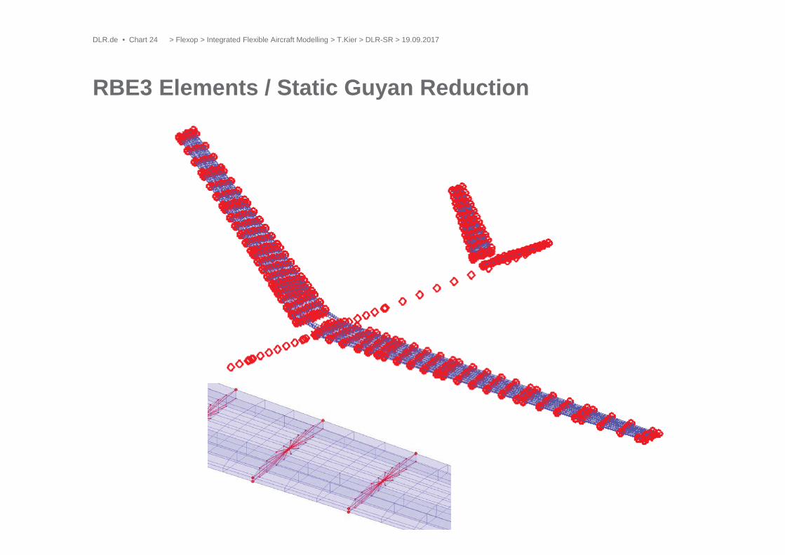
RBE3 Elements / Static Guyan Reduction
> Flexop > Integrated Flexible Aircraft Modelling > T.Kier > DLR-SR > 19.09.2017DLR.de • Chart 24

Aero Interpolation Grid (Rigid Elements in Rib Direction)
> Flexop > Integrated Flexible Aircraft Modelling > T.Kier > DLR-SR > 19.09.2017DLR.de • Chart 25
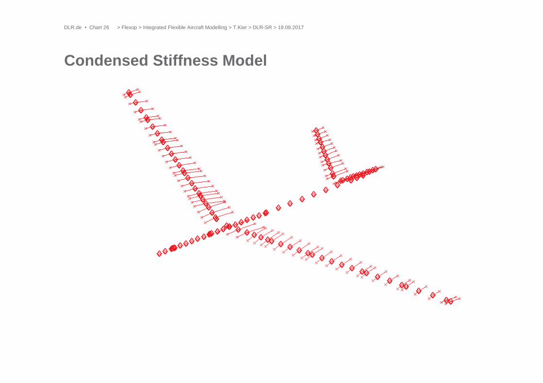
Condensed Stiffness Model
> Flexop > Integrated Flexible Aircraft Modelling > T.Kier > DLR-SR > 19.09.2017DLR.de • Chart 26

Aerodynamic Model: Doublet Lattice Panels
> Flexop > Integrated Flexible Aircraft Modelling > T.Kier > DLR-SR > 19.09.2017DLR.de • Chart 27

Lumped Masses
> Flexop > Integrated Flexible Aircraft Modelling > T.Kier > DLR-SR > 19.09.2017DLR.de • Chart 28

> Flexop > Integrated Flexible Aircraft Modelling > T.Kier > DLR-SR > 19.09.2017DLR.de • Chart 29 > Flexop > Integrated Flexible Aircraft Modelling > T.Kier > DLR-SR > 19.09.2017DLR.de • Chart 29

PK-Method Flutter Analysis(Rodden et al., NASTRAN)
> Flexop > Integrated Flexible Aircraft Modelling > T.Kier > DLR-SR > 19.09.2017DLR.de • Chart 30
The GAF are expanded linearly along the imaginary axis and therefore include aerodynamic damping
+ 14 Im + 12 Re = 0• The eigenvalues become = = 1 +• The damping is recovered by = 2• The converged eigenvalues are determined iteratively until <• Flutter points are found by determining zero crossings of converged damping
wrt. the flight state
-> Not only the flutter points are exact, but the evolution of damping and frequency is approximately physical and can be used to e.g. assess how
quickly a flutter point approaches

• Instead of iterating k and for the tabulated GAFs, a Rational FunctionApproximation of the tabulated GAFs is used directly in the equations.
• The system matrix A then reads
with
• The eigenvalues can be determined directly
P-Method Flutter Analysis
> Flexop > Integrated Flexible Aircraft Modelling > T.Kier > DLR-SR > 19.09.2017DLR.de • Chart 31

• Instead of assembling the system matrix symbolically, the integrated model isnumerically linearized
• Additional effects (nonlinear EOM, nonlinear (control) systems, nonlinearsensor equations, flight state, etc) can be easily considered.
• The integrated model is set up as nonlinear state space system
• The aircraft is trimmed for horizontal flight and linearized about this state• The Eigenvalues are determined for increasing speeds until flutter occurs
Integrated Model P-Method Flutter Analysis
> Flexop > Integrated Flexible Aircraft Modelling > T.Kier > DLR-SR > 19.09.2017DLR.de • Chart 32
),(),(
uxgyuxfx
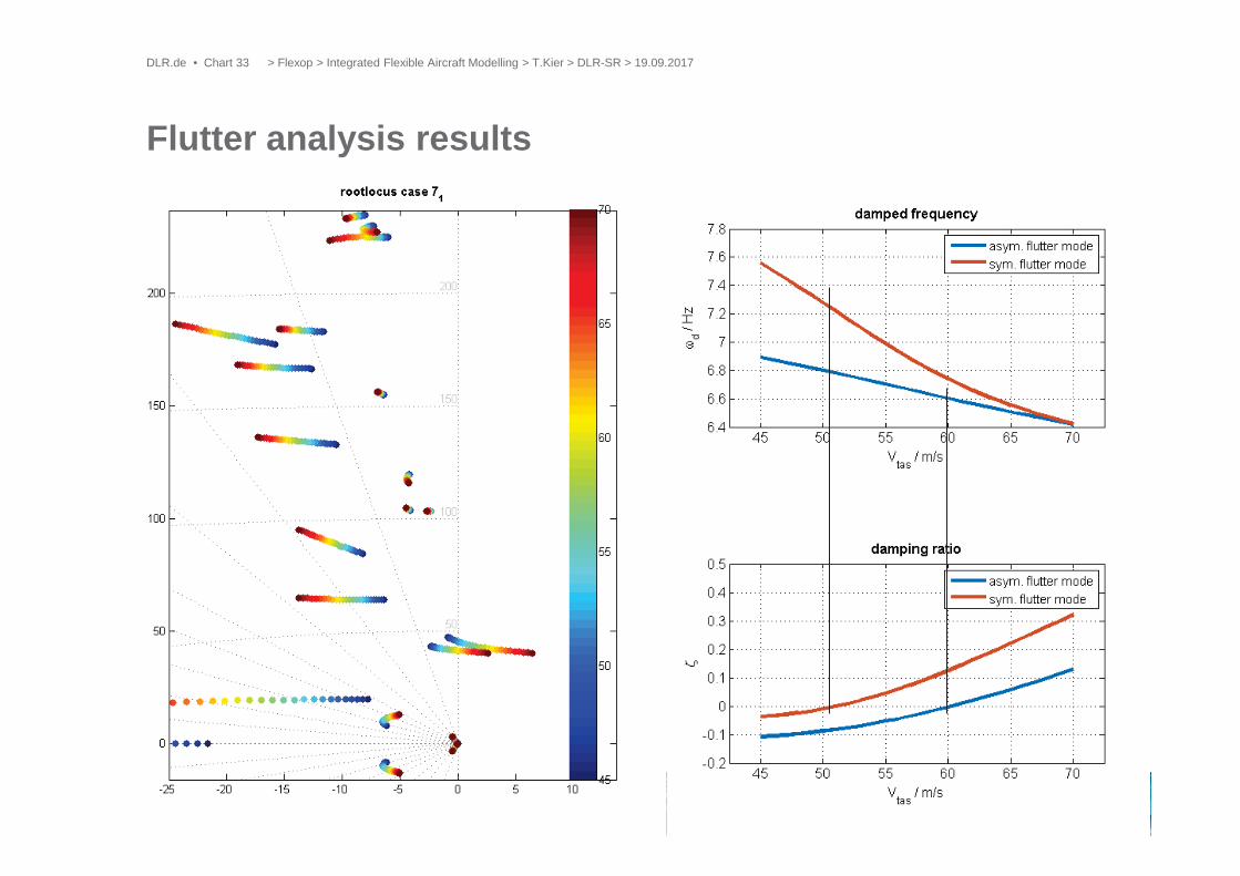
Flutter analysis results
> Flexop > Integrated Flexible Aircraft Modelling > T.Kier > DLR-SR > 19.09.2017DLR.de • Chart 33

• The actuator mass increased significantly to ~0.9 kg• Where should we place it and how does that affect flutter speeds and
mechanisms• 15 candidate positions were examined
Mass Sensitivity of Flutter
> Flexop > Integrated Flexible Aircraft Modelling > T.Kier > DLR-SR > 19.09.2017DLR.de • Chart 34
1
2
3
4
5
6
7
8
9
10
11
12
13
14
15

Symmetrical Flutter Mechanism
> Flexop > Integrated Flexible Aircraft Modelling > T.Kier > DLR-SR > 19.09.2017DLR.de • Chart 35
- -
flutter mass/no actuator
no flutter mass/no actuator

Antisymmetrical flutter
> Flexop > Integrated Flexible Aircraft Modelling > T.Kier > DLR-SR > 19.09.2017DLR.de • Chart 36
- -
a
a
a
a
a
a
a
a
a
flutter mass/no actuatora
no flutter mass/no actuatora

Correction of AICs with CFD data (steady)
> Flexop > Integrated Flexible Aircraft Modelling > T.Kier > DLR-SR > 19.09.2017DLR.de • Chart 37
Correction of AICs with CFD d t (steady)with CFD data (

AIC Correction and AIC-ROM
• Aerodynamic Influence Coefficients (AIC-Matrix)relates local AoA at control points to panel pressures
• I.e. AIC Matrices contain linearized gradientinformation and therefore can easily account forfexibility of the structure
• Mapping of CFD mesh onto VLM/DLM/Panel MethodGrid
• AIC Correction of gradients and offsets with CFD data
• This is repeated for multiple linearization points(different AoA, flight shapes) resulting in multiple AIC-matrices
• POD of AIC-matrices allows nonlinear interpolation
• Advantage over POD of CFD pressures:
Correct only for AoA get flexibility, roll rates, etc. for free ===
DLM CFD
> Flexop > Integrated Flexible Aircraft Modelling > T.Kier > DLR-SR > 19.09.2017DLR.de • Chart 38

Evaluation of AIC-ROM(LANN wing example)
> Flexop > Integrated Flexible Aircraft Modelling > T.Kier > DLR-SR > 19.09.2017DLR.de • Chart 39

> Flexop > Integrated Flexible Aircraft Modelling > T.Kier > DLR-SR > 19.09.2017DLR.de • Chart 40

Thank you for yourattention !
Questions ?
> Flexop > Integrated Flexible Aircraft Modelling > T.Kier > DLR-SR > 19.09.2017DLR.de • Chart 41