Flexim FLUXUS G608 Portable Ultrasonic Flow Measurement of Gas in Hazardous Areas - Datasheet Manual
30
Technical Specification FLUXUS® G608 TSFLUXUS_G608V1-4-1EN_Leu, 2011-03-11 1 FLUXUS G608 supported by handle Measurement with transducers mounted by the portable Variofix VP Measurement with the flow transmitter fixed to the pipe by the QuickFix pipe mounting fixture FLUXUS G608 FLUXUS G608 Portable Ultrasonic Flow Measurement of Gas in Hazardous Areas Portable instrument for non-invasive, quick ultrasonic flow measurement with clamp-on technology for all types of piping Features • Precise bi-directional and highly dynamic flow mea- surement with the non-intrusive clamp-on technology • High precision at fast and slow flow rates, no tempera- ture and zero drift • Portable, easy-to-use flow transmitter with 2 flow chan- nels, multiple inputs/outputs, an integrated data logger with a serial interface • Extremely resistant carbon fiber housing • Covered by ATEX zone 2 certification ( II3G), IP65 protection - No hot work permit required for hazardous areas • Compact and very lightweight, allowing the measuring system to be easily carried as personal luggage, e.g. for offshore visits • Water and dust-tight (IP65); resistant against oil, many liquids and dirt • Li-Ion battery provides up to 14 hours of measurement operation • Automatic loading of calibration data and transducer detection for a fast and easy set-up (less than 5 min), providing precise and long-term stable results • User-friendly design • Transducers available for a wide range of inner pipe di- ameters ( ) and fluid temperatures ( ) • Rugged transducers (ATEX-Zone 1 und 2, resistant to rough environments, dust and humidity) • Robust, water-tight (IP67) transport case with compre- hensive accessories • QuickFix for fast mounting of the flow transmitter in dif- ficult conditions Applications Designed for the following industries: • Upstream (on- and offshore) • Midstream and downstream (pipelines and refineries) • Chemical industry • Energy sector (e.g. HVAC, geothermal, power plants) 7...1600 mm -40...+200 °C
-
Upload
angus-sankaran -
Category
Devices & Hardware
-
view
125 -
download
8
Transcript of Flexim FLUXUS G608 Portable Ultrasonic Flow Measurement of Gas in Hazardous Areas - Datasheet Manual

Technical Specification
FLUXUS® G608
TSFLUXUS_G608V1-4-1EN_Leu, 2011-03-11 1
FLUXUS G608 supported by handle
Measurement with transducers mounted by the portable Variofix VP
Measurement with the flow transmitter fixed to the pipe by the QuickFix pipe mounting fixture
FLUXUS G608
FLUXUS G608
Portable Ultrasonic Flow Measurement of Gas in Hazardous Areas
Portable instrument for non-invasive, quick ultrasonic flow measurement with clamp-on technology for alltypes of piping
Features
• Precise bi-directional and highly dynamic flow mea-surement with the non-intrusive clamp-on technology
• High precision at fast and slow flow rates, no tempera-ture and zero drift
• Portable, easy-to-use flow transmitter with 2 flow chan-nels, multiple inputs/outputs, an integrated data logger with a serial interface
• Extremely resistant carbon fiber housing
• Covered by ATEX zone 2 certification ( II3G), IP65 protection - No hot work permit required for hazardous areas
• Compact and very lightweight, allowing the measuring system to be easily carried as personal luggage, e.g. for offshore visits
• Water and dust-tight (IP65); resistant against oil, many liquids and dirt
• Li-Ion battery provides up to 14 hours of measurement operation
• Automatic loading of calibration data and transducer detection for a fast and easy set-up (less than 5 min), providing precise and long-term stable results
• User-friendly design
• Transducers available for a wide range of inner pipe di-ameters ( ) and fluid temperatures ( )
• Rugged transducers (ATEX-Zone 1 und 2, resistant to rough environments, dust and humidity)
• Robust, water-tight (IP67) transport case with compre-hensive accessories
• QuickFix for fast mounting of the flow transmitter in dif-ficult conditions
ApplicationsDesigned for the following industries:
• Upstream (on- and offshore)
• Midstream and downstream (pipelines and refineries)
• Chemical industry
• Energy sector (e.g. HVAC, geothermal, power plants)
7...1600 mm-40...+200 °C

FLUXUS® G608 Technical Specification
Table of Contents
TSFLUXUS_G608V1-4-1EN_Leu, 2011-03-112
Function ........................................................................................................................................................... 3
Measurement Principle ..................................................................................................................................... 3
Calculation of Volumetric Flow Rate ................................................................................................................. 3
Number of Sound Paths.................................................................................................................................... 4
Typical Measurement Setup ............................................................................................................................. 5
Standard Volumetric Flow Rate ........................................................................................................................ 6
Flow Transmitter ............................................................................................................................................. 7
Technical Data .................................................................................................................................................. 7
Dimensions ....................................................................................................................................................... 9
Standard Scope of Supply ................................................................................................................................ 9
Adapters (optional).......................................................................................................................................... 10
Transducers................................................................................................................................................... 12
Transducer Selection ...................................................................................................................................... 12
Transducer Order Code .................................................................................................................................. 15
Technical Data ................................................................................................................................................ 16
Transducer Mounting Fixture ...................................................................................................................... 25
Coupling Materials for Transducers............................................................................................................ 26
Connection Systems..................................................................................................................................... 27
Transducer Cable............................................................................................................................................ 27
Damping Mats (optional) .............................................................................................................................. 28
Clamp-on Temperature Probe (optional) .................................................................................................... 29

TSFLUXUS_G608V1-4-1EN_Leu, 2011-03-11 3
Technical Specification FLUXUS® G608
Function
Measurement Principle
In order to measure the flow of a medium in a pipe, ultrasonic signals are used, employing the transit time dif-ference principle. Ultrasonic signals are emitted by a transducer installed on the pipe and received by a sec-ond transducer. These signals are emitted alternately in the flow direction and against it.
As the medium in which the signals propagate is flowing, the transit time of the ultrasonic signals in the flowdirection is shorter than against the flow direction.
The transit time difference, Δt, is measured and allows the flowmeter to determine the average flow velocityalong the propagation path of the ultrasonic signals. A flow profile correction is then performed in order to ob-tain the area averaged flow velocity, which is proportional to the volumetric flow rate.
Two integrated microprocessors control the entire measuring process. This allows the flowmeter to removedisturbance signals, and to check each received ultrasonic wave for its validity which reduces noise.
Calculation of Volumetric Flow Rate
Q = kRe . A . ka . Δt/(2 . tfl)
where:
Path of the ultrasonic signal Transit time difference Δt
Q - volumetric flow ratekRe - fluid mechanics calibration factorA - cross-sectional pipe areaka - acoustical calibration factorΔt - transit time differencetfl - transit time in the medium

4 TSFLUXUS_G608V1-4-1EN_Leu, 2011-03-11
FLUXUS® G608 Technical Specification
Number of Sound Paths
The number of sound paths is the number of transits of the ultrasonic signal through the medium in the pipe.Depending on the number of sound paths, the following methods of installation exist:
• reflection modeThe number of sound paths is even. Both of the transducers are mounted on the same side of the pipe. Correct positioning of the transducers is easier.
• diagonal modeThe number of sound paths is odd. Both of the transducers are mounted on opposite sides of the pipe. In the case of a high signal attenuation by the medium, pipe and coatings, diagonal mode with 1 sound path will be used.
The preferred method of installation depends on the application. While increasing the number of sound pathsincreases the accuracy of the measurement, signal attenuation increases as well. The optimum number ofsound paths for the parameters of the application will be determined automatically by the transmitter.
As the transducers can be mounted with the transducer mounting fixture in reflection mode or diagonal mode,the number of sound paths can be adjusted optimally for the application..
a - transducer distance
Reflection mode, number of sound paths: 2
Diagonal mode, number of sound paths: 3
Diagonal mode, number of sound paths: 1 Diagonal mode, number of sound paths: 1,negative transducer distance
a
a
a > 0 a < 0

TSFLUXUS_G608V1-4-1EN_Leu, 2011-03-11 5
Technical Specification FLUXUS® G608
Typical Measurement Setup
ATEX zone 2
ATEX zone 2/ATEX zone 1
!
" # " $ %
transmitter
analog/binary outputs
ATEX zone 2
damping mat
outside of explosive atmosphere
output adapter
(power adapter)
transducers
!
" # " $ %
ATEX zone 2 ATEX zone 1
transducers
transmitter
analog/binary outputs
damping mat
outside of explosive atmosphere
(power adapter)
output adapter

6 TSFLUXUS_G608V1-4-1EN_Leu, 2011-03-11
FLUXUS® G608 Technical Specification
Standard Volumetric Flow Rate
The standard volumetric flow rate can be selected as physical quantity to be measured. It will be calculated in-ternally by:
QN = Q. p/pN . TN/T . 1/K
where:
The operational pressure p and the operational temperature T of the medium will be entered directly as fixedvalues into the transmitter.
The gas compressibility factor K will be entered in the transmitter:
• as fixed value or
• as approximation according to e.g. AGA8 or GERG
QN - standard volumetric flow rateQ - operating volumetric flow ratepN - standard pressure (absolute value)p - operating pressure (absolute value)TN - standard temperature in KT - operating temperature in KK - gas compressibility factor

TSFLUXUS_G608V1-4-1EN_Leu, 2011-03-11 7
Technical Specification FLUXUS® G608
Flow Transmitter
Technical Data
FLUXUS G608**-A2design portable, ATEX zone 2
measurementmeasurement principle transit time difference correlation principleflow velocity 0.01...35 m/s, depending on pipe diameterrepeatability 0.15 % of reading ±0.01 m/smedium all acoustically conductive gases,
e.g. nitrogen, air, oxygen, hydrogen, argon, helium, ethylene, propanetemperature compensation corresponding to the recommendations in ANSI/ASME MFC-5M-1985
accuracy- volumetric flow rate ± 1...3 % of reading ±0.01 m/s depending on application
± 0.5 % of reading ±0.01 m/s with field calibrationflow transmitterpower supply 100...240 V/50...60 Hz (power supply unit, outside of explosive atmosphere),
10.5...15 V DC (socket at transmitter, with power adapter (optional)), Um = 16 V,integrated battery
battery Li-Ion, 7.2 V/4.5 Ahoperating time (without outputs, inputs and backlight): > 14 h
power consumption < 6 Wnumber of flow measuring channels
2
signal attenuation 0...100 s, adjustablemeasuring cycle (1 channel) 100...1000 Hzresponse time 1 s (1 channel), option: 70 mshousing material PA, TPS, PC, Polyester, stainless steeldegree of protection accord-ing to IEC/EN 60529
IP65
dimensions see dimensional drawingweight 1.9 kgfixation QuickFix pipe mounting fixtureoperating temperature -10...+60 °Cdisplay 2 x 16 characters, dot matrix, backlightmenu language English, German, French, Dutch, Spanishexplosion protection
ATEX
categoryEPLzone
gas: 3G dust: 2D Gc Db 2 21
marking 0637 II3G Ex nA nC ic IIC (T6)T4 GcII2D Ex tb IIIC T 100 °C DbTa -10...+(50)60 °C
certification IBExU10ATEX1067type of protection gas: non sparking
dust: protection by enclosure

8 TSFLUXUS_G608V1-4-1EN_Leu, 2011-03-11
FLUXUS® G608 Technical Specification
measuring functionsphysical quantities operating volumetric flow rate, standard volumetric flow rate, mass flow rate, flow velocitytotalizer volume, masscalculation functions average, difference, sumdiagnostic functions sound speed, signal amplitude, SNR, SCNR, standard deviation of amplitudes and transit timesdata loggerloggable values all physical quantities, totalized values and diagnostic valuescapacity > 100 000 measured valuescommunicationinterface RS232/USBserial data kitsoftware (all Windows™ ver-sions)
- FluxData: download of measurement data, graphical presentation,conversion to other formats (e.g. for Excel™)
- FluxKoef: creating medium data setsсable RS232adapter RS232 - USBtransport casedimensions 500 x 400 x 190 mmoutputs
The outputs are galvanically isolated from the transmitter.number see standard scope of supply on page 9accessories output adapter (optional)
current outputrange 0/4...20 mAaccuracy 0.1 % of reading ±15 μApassive output Uext = 4...9 V, depending on Rext
Rext < 200 Ωbinary output
optorelay 26 V/100 mAbinary output as alarm output- functions limit, change of flow direction or errorbinary output as pulse output- pulse value 0.01...1000 units- pulse width 1...1000 ms
FLUXUS G608**-A2

TSFLUXUS_G608V1-4-1EN_Leu, 2011-03-11 9
Technical Specification FLUXUS® G608
Dimensions
Standard Scope of Supply
in mm
G608 Standardorder code FLUXUS G608**-A22-3N-NN-2D-II-NN-NNapplication all flow measurements on gasoutputspassive current output 2binary output 2inputstemperature input -accessoriestransport case xpower supply unit, mains cable
x
battery xQuickFix pipe mounting fixture for transmitter
x
serial data kit xmeasuring tape xuser manual,safety instructions,Quick Start Guide
x
connector board at the upper side of the transmitter
!
" # " $ %
226
5921
3
! $ ! "
& ' ( & '
! !

10 TSFLUXUS_G608V1-4-1EN_Leu, 2011-03-11
FLUXUS® G608 Technical Specification
Adapters (optional)
Technical Data
output adapter power adaptertechnical type OA608A2 PA608A2dimensions see dimensional drawingweight kg 0.36 0.29materialhousing polyestergasket siliconedegree of protection according to IEC/EN 60529
IP66
operating temperaturemin. °C -20max. °C +90explosion protection
ATEX
zone 2marking
II3G Ex nA II T6 GcTa -20...+60 °C
type of protection non sparking
! $
& ' ( & '
! !
! "
output adapter
transducersmeasuring channel A
RS232 outputs
transducersmeasuring channel B
power supply unit/battery charging unit
power adapter

TSFLUXUS_G608V1-4-1EN_Leu, 2011-03-11 11
Technical Specification FLUXUS® G608
Dimensions
Terminal Assignment
output adapter power adapter
in mm
output adapter power adapter
110 55
75
55
75
80

12 TSFLUXUS_G608V1-4-1EN_Leu, 2011-04-29
FLUXUS® G608 Technical Specification
Transducers
Transducer Selection
Step 1a
Select a Lamb wave transducer:
Step 1b
If the pipe wall thickness is not in the range of the Lamb wave transducers, select a shear wave transducer:
Step 2
inner pipe diameter d dependent on the flow velocity v of the medium in the pipe
The transducers are selected from the characteristics (see next page). Lamb wave transducers are selectedfrom the left column, shear wave transducers from the right column.
Lamb wave transducers: If the values d and v are not in the range, diagonal mode with 1 sound path may beused, i.e. the same characteristics can be used with doubling the inner pipe diameter. If the values are still notin the range, shear waves transducers regarding the pipe wall thickness have to be selected in step 1b.
transducer order code
GLG 11 23
GLH 7 15
GLK 4 9
GLM 2 5
GLP 1...3
GLQ 0.5...1
5 10 15 20 25pipe wall thickness [mm]
transducer order code
GSG 14 23
GSK 5 9
GSM 2.5 5
GSP 1.5 3
5 10 15 20 25pipe wall thickness [mm]
recommended possible

TSFLUXUS_G608V1-4-1EN_Leu, 2011-03-11 13
Technical Specification FLUXUS® G608
Lamb wave transducer1 shear wave transducer1
GLG GSG
GLH
GLK GSK
GLM GSM
GLP
GSP
GLQ
1 inner pipe diameter and max. flow velocity for a typical application with natural gas, nitrogen, oxygen in reflection mode with 2 soundpaths (Lamb wave transducers)/1 sound path (shear wave transducers)
0 5 10 15 20 25 30 35vms
200
400
600
800
1000
1200Dmm
0 5 10 15 20 25 30 35vms
200
400
600
800
1000
1200Dmm
0 5 10 15 20 25 30 35vms
200
400
600
800
1000
1200Dmm
0 5 10 15 20 25 30 35vms
200
400
600
800
1000
1200Dmm
0 5 10 15 20 25 30 35vms
200
400
600
800
1000
1200Dmm
0 5 10 15 20 25 30 35vms
20
40
60
80
100
120
140
Dmm
0 5 10 15 20 25 30 35vms
20
40
60
80
100
120
140
Dmm
0 5 10 15 20 25 30 35vms
20
40
60
80
100
120
140
Dmm
0 5 10 15 20 25 30 35vms
20
40
60
80
100
120
140
DmmGDP
0 5 10 15 20 25 30 35vms
20
40
60
80
100
120
140
Dmm

14 TSFLUXUS_G608V1-4-1EN_Leu, 2011-03-11
FLUXUS® G608 Technical Specification
Step 3
min. medium pressure
Example
Step 4
for the characters 4...11 of the transducer order code (operating temperature, explosion protection, connectionsystem, extension cable) see page 15
Step 5
for the technical data of the selected transducer see page 16 et seqq.
Lamb wave transducer shear wave transducertransducer order code
medium pressure1 [bar] transducer order code
medium pressure1 [bar]metal pipe plastic pipe metal pipe plastic pipe
min. min. extended min. min. min. extended min.GLG 15 10 1 GSG 30 20 1
GLH 15 10 1 GSK 30 20 1
GLK 15 (d > 120 mm)10 (d < 120 mm)
10 (d > 120 mm)5 (d < 120 mm)
1 GSM 30 20 1
GLM 10 (d > 60 mm)5 (d < 60 mm)
- 1 GSP 30 20 1
GLP 10 (d > 35 mm)5 (d < 35 mm)
- 1
GLQ 10 (d > 15 mm)5 (d < 15 mm)
- 1
1 depending on application, typical absolute value for natural gas, nitrogen, compressed air
d - inner pipe diameter
step1 pipe wall thickness mm 12 12 12 30
selected transducer GLG or GLH GLG or GLH GLG or GLH GS2 inner pipe diameter mm 800 600 800 300
max. flow velocity m/s 15 15 30 15selected transducer GLG GLG or GLH values not in the range
of the characteristics, but by using diagonal mode with 1 sound path, the inner pipe diameter in the cha-racteristics is doubled:GLG
GSK
3 min. medium pressure bar 17 17 17 35selected transducer GLG GLG or GLH
influence of acoustic noise is reduced with increased transducer frequency, thus recommended:GLH
GLG GSK
TSFLUXUS_G608V1-4-1EN_Leu, 2011-03-11 15
Technical Specification FLUXUS® G608
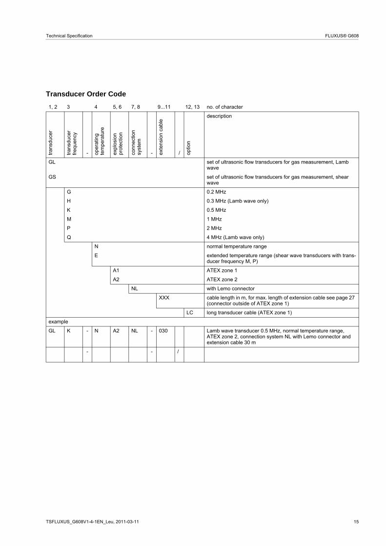
Transducer Order Code
1, 2 3 4 5, 6 7, 8 9...11 12, 13 no. of character
tra
nsdu
cer
tra
nsdu
cer
fre
quen
cy
- oper
atin
g te
mpe
ratu
re
expl
osi
onpr
otec
tion
conn
ectio
nsy
stem
- exte
nsio
n ca
ble
/ optio
n
description
GL set of ultrasonic flow transducers for gas measurement, Lamb wave
GS set of ultrasonic flow transducers for gas measurement, shear wave
G 0.2 MHz
H 0.3 MHz (Lamb wave only)
K 0.5 MHz
M 1 MHz
P 2 MHz
Q 4 MHz (Lamb wave only)
N normal temperature range
E extended temperature range (shear wave transducers with trans-ducer frequency M, P)
A1 ATEX zone 1
A2 ATEX zone 2
NL with Lemo connector
XXX cable length in m, for max. length of extension cable see page 27 (connector outside of ATEX zone 1)
LC long transducer cable (ATEX zone 1)
example
GL K - N A2 NL - 030 Lamb wave transducer 0.5 MHz, normal temperature range, ATEX zone 2, connection system NL with Lemo connector and extension cable 30 m
- - /

16 TSFLUXUS_G608V1-4-1EN_Leu, 2011-03-11
FLUXUS® G608 Technical Specification
Technical Data
Shear Wave Transducers (zone 1)
technical type GDG1NW1 GLG1NW1 GDK1NW1 GLK1NW1 GDM2NW1 GLM2NW1order code GSG-NA1NL GSG-NA1NL/LC GSK-NA1NL GSK-NA1NL/LC GSM-NA1NL GSM-NA1NL/LCtransducer frequency MHz 0.2 0.5 1
medium pressure1
min. extended bar metal pipe: 20 metal pipe: 20 metal pipe: 20min. bar metal pipe: 30
plastic pipe: 1metal pipe: 30plastic pipe: 1
metal pipe: 30plastic pipe: 1
inner pipe diameter d2
min. extended mm 250 70 30min. recommended mm 380 80 40max. recommended mm 810 500 80max. extended mm 1100 720 120pipe wall thicknessmin. mm 14 5 2.5max. mm - - -materialhousing PEEK with stainless steel cap and
transducer shoe 304 (1.4301)PEEK with stainless steel cap and
transducer shoe 304 (1.4301)PEEK with stainless steel cap and
transducer shoe 304 (1.4301)contact surface PEEK PEEK PEEKdegree of protection according to IEC/EN 60529
IP65 IP65 IP65
transducer cabletype 1699 1699 1699 1699 1699 1699length m 5 9 5 9 4 9dimensionslength l mm 136.5 136.5 84width b mm 59 59 40height h mm 90.5 90.5 59dimensional drawing
operating temperaturemin. °C -40 -40 -40max. °C +130 +130 +130temperaturecompensation
x x x
explosion protection
ATEX
transducer GSG-NA1NL GSG-NA1NL/LC GSK-NA1NL GSK-NA1NL/LC GSM-NA1NL GSM-NA1NL/LCcategoryEPLzone
gas: 2/3G dust: 2D Gb/Gc Db 1/2 21
gas: 2/3G dust: 2D Gb/Gc Db 1/2 21
gas: 2/3G dust: 2D Gb/Gc Db 1/2 21
explosion protection temperature (pipe surface)min. °C -55 -55 -55max. °C +180 +180 +180marking 0637
II2/3G Ex q nA IIC T6...T2 Gb/GcII2D Ex tb IIIC TX
0637 II2/3G Ex q nA IIC T6...T2 Gb/Gc
II2D Ex tb IIIC TX
0637 II2/3G Ex q nA IIC T6...T2 Gb/Gc
II2D Ex tb IIIC TXcertification IBExU10ATEX1162 X IBExU10ATEX1162 X IBExU10ATEX1162 Xtype of protection gas: powder filling,
non sparkingdust: protection by enclosure
gas: powder filling,non sparking
dust: protection by enclosure
gas: powder filling,non sparking
dust: protection by enclosurenecessary trans-ducer mountingfixture
- - -
1 depending on application, typical absolute value for natural gas, nitrogen, compressed air2 shear wave transducer:
typical values for natural gas, nitrogen, oxygen, pipe diameters for other gases on requestpipe diameter min. recommended/max. recommended/max. extended: in diagonal mode and for a flow velocity of 15 m/s
l
hb
l
hb
l
hb

TSFLUXUS_G608V1-4-1EN_Leu, 2011-03-11 17
Technical Specification FLUXUS® G608
Shear Wave Transducers (zone 1)
technical type GDP2NW1 GLP2NW1order code GSP-NA1NL GSP-NA1NL/LCtransducer frequency MHz 2
medium pressure1
min. extended bar metal pipe: 20min. bar metal pipe: 30
plastic pipe: 1
inner pipe diameter d2
min. extended mm 15min. recommended mm 20max. recommended mm 40max. extended mm 60pipe wall thicknessmin. mm 1.5max. mm -materialhousing PEEK with stainless steel cap and
transducer shoe 304 (1.4301)contact surface PEEKdegree of protection according to IEC/EN 60529
IP65
transducer cabletype 1699 1699length m 4 9dimensionslength l mm 84width b mm 40height h mm 59dimensional drawing
operating temperaturemin. °C -40max. °C +130temperaturecompensation
x
explosion protection
ATEX
transducer GSP-NA1NL GSP-NA1NL/LCcategoryEPLzone
gas: 2/3G dust: 2D Gb/Gc Db 1/2 21
explosion protection temperature (pipe surface)min. °C -55max. °C +180marking 0637
II2/3G Ex q nA IIC T6...T2 Gb/GcII2D Ex tb IIIC TX
certification IBExU10ATEX1162 Xtype of protection gas: powder filling,
non sparkingdust: protection by enclosure
necessary trans-ducer mountingfixture
-
1 depending on application, typical absolute value for natural gas, nitrogen, compressed air2 shear wave transducer:
typical values for natural gas, nitrogen, oxygen, pipe diameters for other gases on requestpipe diameter min. recommended/max. recommended/max. extended: in diagonal mode and for a flow velocity of 15 m/s
l
hb

18 TSFLUXUS_G608V1-4-1EN_Leu, 2011-03-11
FLUXUS® G608 Technical Specification
Shear Wave Transducers (zone 1, extended temperature range)
technical type GDM2EW5 GLM2EW5 GDP2EW5 GLP2EW5order code GSM-EA1NL GSM-EA1NL/LC GSP-EA1NL GSP-EA1NL/LCtransducer frequency MHz 1 2
medium pressure1
min. extended bar metal pipe: 20 metal pipe: 20min. bar metal pipe: 30
plastic pipe: 1metal pipe: 30plastic pipe: 1
inner pipe diameter d2
min. extended mm 30 15min. recommended mm 40 20max. recommended mm 80 40max. extended mm 120 60pipe wall thicknessmin. mm 2.5 1.5max. mm - -materialhousing PI with stainless steel cap and
transducer shoe 304 (1.4301)PI with stainless steel cap and transducer shoe 304 (1.4301)
contact surface PI PIdegree of protection according to IEC/EN 60529
IP56 IP56
transducer cabletype 6111 6111 6111 6111length m 4 9 4 9dimensionslength l mm 84 84width b mm 40 40height h mm 59 59dimensional drawing
operating temperaturemin. °C -30 -30max. °C +200 +200temperaturecompensation
x x
explosion protection
ATEX
transducer GSM-EA1NL GSM-EA1NL/LC GSP-EA1NL GSP-EA1NL/LCcategoryEPLzone
gas :2/3G dust: 2D Gb/Gc Db 1/2 21
gas: 2/3G dust: 2D Gb/Gc Db 1/2 21
explosion protection temperature (pipe surface)min. °C -45 -45max. °C +225 +225marking 0637
II2/3G Ex q nA IIC T6...T2 Gb/GcII2D Ex tb IIIA TX
0637 II2/3G Ex q nA IIC T6...T2 Gb/Gc
II2D Ex tb IIIA TXcertification IBExU10ATEX1162 X IBExU10ATEX1162 Xtype of protection gas: powder filling,
non sparkingdust: protection by enclosure
gas: powder filling,non sparking
dust: protection by enclosurenecessary trans-ducer mountingfixture
- -
1 depending on application, typical absolute value for natural gas, nitrogen, compressed air2 shear wave transducer:
typical values for natural gas, nitrogen, oxygen, pipe diameters for other gases on requestpipe diameter min. recommended/max. recommended/max. extended: in diagonal mode and for a flow velocity of 15 m/s
l
hb
l
hb

TSFLUXUS_G608V1-4-1EN_Leu, 2011-03-11 19
Technical Specification FLUXUS® G608
Shear Wave Transducers (zone 2)
technical type GDG1NH1 GDK1NH1 GDM2NH1 GDP2NH1order code GSG-NA2NL GSK-NA2NL GSM-NA2NL GSP-NA2NLtransducer frequency MHz 0.2 0.5 1 2
medium pressure1
min. extended bar metal pipe: 20 metal pipe: 20 metal pipe: 20 metal pipe: 20min. bar metal pipe: 30
plastic pipe: 1metal pipe: 30plastic pipe: 1
metal pipe: 30plastic pipe: 1
metal pipe: 30plastic pipe: 1
inner pipe diameter d2
min. extended mm 250 70 30 15min. recommended mm 380 80 40 20max. recommended mm 810 500 80 40max. extended mm 1100 720 120 60pipe wall thicknessmin. mm 14 5 2.5 1.5max. mm - - - -materialhousing PEEK with stainless steel
cap and transducer shoe 304 (1.4301)
PEEK with stainless steel cap and transducer shoe 304 (1.4301)
PEEK with stainless steel cap and transducer shoe 304 (1.4301)
PEEK with stainless steel cap and transducer shoe 304 (1.4301)
contact surface PEEK PEEK PEEK PEEKdegree of protection according to IEC/EN 60529
IP65 IP65 IP65 IP65
transducer cabletype 1699 1699 1699 1699length m 5 5 4 4dimensionslength l mm 136.5 136.5 84 84width b mm 59 59 40 40height h mm 90.5 90.5 59 59dimensional drawing
operating temperaturemin. °C -40 -40 -40 -40max. °C +130 +130 +130 +130temperaturecompensation
x x x x
explosion protection
ATEX
transducer GSG-NA2NL GSK-NA2NL GSM-NA2NL GSP-NA2NLcategoryEPLzone
gas: 3G dust: 2D Gc Db 2 21
gas: 3G dust: 2D Gc Db 2 21
gas: 3G dust: 2D Gc Db 2 21
gas: 3G dust: 2D Gc Db 2 21
explosion protection temperature (pipe surface)min. °C -55 -55 -55 -55max. °C +190 +190 +190 +190marking 0637
II3G Ex nA IIC T6...T2 Gc XII2D Ex tb IIIC TX Db
0637 II3G Ex nA IIC T6...T2 Gc XII2D Ex tb IIIC TX Db
0637 II3G Ex nA IIC T6...T2 Gc XII2D Ex tb IIIC TX Db
0637 II3G Ex nA IIC T6...T2 Gc XII2D Ex tb IIIC TX Db
certification IBExU10ATEX1163 X IBExU10ATEX1163 X IBExU10ATEX1163 X IBExU10ATEX1163 Xtype of protection gas: non sparking
dust: protection by enclo-sure
gas: non sparkingdust: protection by enclo-sure
gas: non sparkingdust: protection by enclo-sure
gas: non sparkingdust: protection by enclo-sure
necessary trans-ducer mountingfixture
- - - -
1 depending on application, typical absolute value for natural gas, nitrogen, compressed air2 shear wave transducer:
typical values for natural gas, nitrogen, oxygen, pipe diameters for other gases on requestpipe diameter min. recommended/max. recommended/max. extended: in diagonal mode and for a flow velocity of 15 m/s
l
hb
l
hb
l
hb
l
hb

20 TSFLUXUS_G608V1-4-1EN_Leu, 2011-03-11
FLUXUS® G608 Technical Specification
Shear Wave Transducers (zone 2, extended temperature range)
technical type GDM2EH5 GDP2EH5order code GSM-EA2NL GSP-EA2NLtransducer frequency MHz 1 2
medium pressure1
min. extended bar metal pipe: 20 metal pipe: 20min. bar metal pipe: 30
plastic pipe: 1metal pipe: 30plastic pipe: 1
inner pipe diameter d2
min. extended mm 30 15min. recommended mm 40 20max. recommended mm 80 40max. extended mm 120 60pipe wall thicknessmin. mm 2.5 1.5max. mm - -materialhousing PI with stainless steel cap
and transducer shoe 304 (1.4301)
PI with stainless steel cap and transducer shoe 304 (1.4301)
contact surface PI PIdegree of protection according to IEC/EN 60529
IP56 IP56
transducer cabletype 6111 6111length m 4 4dimensionslength l mm 84 84width b mm 40 40height h mm 59 59dimensional drawing
operating temperaturemin. °C -30 -30max. °C +200 +200temperaturecompensation
x x
explosion protection
ATEX
transducer GSM-EA2NL GSP-EA2NLcategoryEPLzone
gas: 3G dust: 2DGc Db 2 21
gas: 3G dust: 2D Gc Db 2 21
explosion protection temperature (pipe surface)min. °C -45 -45max. °C +235 +235marking 0637
II3G Ex nA IIC T6...T2 Gc XII2D Ex tb IIIA TX Db
0637 II3G Ex nA IIC T6...T2 Gc XII2D Ex tb IIIA TX Db
certification IBExU10ATEX1163 X IBExU10ATEX1163 Xtype of protection gas: non sparking
dust: protection by enclo-sure
gas: non sparkingdust: protection by enclo-sure
necessary trans-ducer mountingfixture
- -
1 depending on application, typical absolute value for natural gas, nitrogen, compressed air2 shear wave transducer:
typical values for natural gas, nitrogen, oxygen, pipe diameters for other gases on requestpipe diameter min. recommended/max. recommended/max. extended: in diagonal mode and for a flow velocity of 15 m/s
l
hb
l
hb

TSFLUXUS_G608V1-4-1EN_Leu, 2011-03-11 21
Technical Specification FLUXUS® G608
Lamb Wave Transducers (zone 1)
technical type GRG1NW3 GTG1NW3 GRH1NW3 GTH1NW3 GRK1NW3 GTK1NW3order code GLG-NA1NL GLG-NA1NL/LC GLH-NA1NL GLH-NA1NL/LC GLK-NA1NL GLK-NA1NL/LCtransducer frequency MHz 0.2 0.3 0.5
medium pressure1
min. extended bar metal pipe: 10 metal pipe: 10 metal pipe:10 (d > 120 mm), 5 (d < 120 mm)
min. bar metal pipe: 15plastic pipe: 1
metal pipe: 15plastic pipe: 1
metal pipe:15 (d > 120 mm), 10 (d < 120 mm)
plastic pipe: 1
inner pipe diameter d2
min. extended mm 190 120 60min. recommended mm 220 140 80max. recommended mm 900 600 300max. extended mm 1600 1000 500pipe wall thicknessmin. mm 11 7 4max. mm 23 15 9materialhousing PPSU with stainless steel cap and
transducer shoe 304 (1.4301)PPSU with stainless steel cap and
transducer shoe 304 (1.4301)PPSU with stainless steel cap and
transducer shoe 304 (1.4301)contact surface PPSU PPSU PPSUdegree of protection according to IEC/EN 60529
IP65 IP65 IP65
transducer cabletype 1699 1699 1699 1699 1699 1699length m 5 9 5 9 5 9dimensionslength l mm 136.5 136.5 136.5width b mm 59 59 59height h mm 90.5 90.5 90.5dimensional drawing
operating temperaturemin. °C -40 -40 -40max. °C +170 +170 +170temperaturecompensation
x x x
explosion protection
ATEX
transducer GLG-NA1NL GLG-NA1NL/LC GLH-NA1NL GLH-NA1NL/LC GLK-NA1NL GLK-NA1NL/LCcategoryEPLzone
gas: 2/3G dust: 2D Gb/Gc Db 1/2 21
gas: 2/3G dust: 2D Gb/Gc Db 1/2 21
gas: 2/3G dust: 2D Gb/Gc Db 1/2 21
explosion protection temperature (pipe surface)min. °C -55 -55 -55max. °C +140 +140 +140marking 0637
II2/3G Ex q nA IIC T6...T2 Gb/GcII2D Ex tb IIIC TX
0637 II2/3G Ex q nA IIC T6...T2 Gb/Gc
II2D Ex tb IIIC TX
0637 II2/3G Ex q nA IIC T6...T2 Gb/Gc
II2D Ex tb IIIC TXcertification IBExU10ATEX1162 X IBExU10ATEX1162 X IBExU10ATEX1162 Xtype of protection gas: powder filling,
non sparkingdust: protection by enclosure
gas: powder filling,non sparking
dust: protection by enclosure
gas: powder filling,non sparking
dust: protection by enclosurenecessary trans-ducer mountingfixture
- - -
1 depending on application, typical absolute value for natural gas, nitrogen, compressed air2 Lamb wave transducer:
typical values for natural gas, nitrogen, oxygen, pipe diameters for other gases on requestpipe diameter min. recommended/max. recommended: in reflection mode and for a flow velocity of 15 m/spipe diameter max. extended: in diagonal mode and for a flow velocity of 25 m/s
l
hb
l
hb
l
hb

22 TSFLUXUS_G608V1-4-1EN_Leu, 2011-03-11
FLUXUS® G608 Technical Specification
Lamb Wave Transducers (zone 1)
technical type GRM1NW3 GTM1NW3 GRP1NW3 GTP1NW3 GRQ1NW3 GTQ1NW3order code GLM-NA1NL GLM-NA1NL/LC GLP-NA1NL GLP-NA1NL/LC GLQ-NA1NL GLQ-NA1NL/LCtransducer frequency MHz 1 2 4
medium pressure1
min. extended bar - - -min. bar metal pipe:
10 (d > 60 mm), 5 (d < 60 mm)plastic pipe: 1
metal pipe:10 (d > 35 mm), 5 (d < 35 mm)
plastic pipe: 1
metal pipe:10 (d > 15 mm), 5 (d < 15 mm)
plastic pipe: 1
inner pipe diameter d2
min. extended mm 30 15 7min. recommended mm 40 20 10max. recommended mm 90 50 22max. extended mm 150 70 35pipe wall thicknessmin. mm 2 1 0.5max. mm 5 3 1materialhousing PPSU with stainless steel cap and
transducer shoe 304 (1.4301)PPSU with stainless steel cap and
transducer shoe 304 (1.4301)PPSU with stainless steel cap and
transducer shoe 304 (1.4301)contact surface PPSU PPSU PPSUdegree of protection according to IEC/EN 60529
IP65 IP65 IP65
transducer cabletype 1699 1699 1699 1699 1699 1699length m 4 9 4 9 4 9dimensionslength l mm 84 84 70width b mm 40 40 30height h mm 59 59 47.5dimensional drawing
operating temperaturemin. °C -40 -40 -40max. °C +170 +170 +170temperaturecompensation
x x x
explosion protection
ATEX
transducer GLM-NA1NL GLM-NA1NL/LC GLP-NA1NL GLP-NA1NL/LC GLQ-NA1NL GLQ-NA1NL/LCcategoryEPLzone
gas: 2/3G dust: 2D Gb/Gc Db 1/2 21
gas: 2/3G dust: 2D Gb/Gc Db 1/2 21
gas: 2/3G dust: 2D Gb/Gc Db 1/2 21
explosion protection temperature (pipe surface)min. °C -55 -55 -55max. °C +140 +140 +140marking 0637
II2/3G Ex q nA IIC T6...T2 Gb/GcII2D Ex tb IIIC TX
0637 II2/3G Ex q nA IIC T6...T2 Gb/Gc
II2D Ex tb IIIC TX
0637 II2/3G Ex q nA IIC T6...T2 Gb/Gc
II2D Ex tb IIIC TXcertification IBExU10ATEX1162 X IBExU10ATEX1162 X IBExU10ATEX1162 Xtype of protection gas: powder filling,
non sparkingdust: protection by enclosure
gas: powder filling,non sparking
dust: protection by enclosure
gas: powder filling,non sparking
dust: protection by enclosurenecessary trans-ducer mountingfixture
- - -
remark on request1 depending on application, typical absolute value for natural gas, nitrogen, compressed air2 Lamb wave transducer:
typical values for natural gas, nitrogen, oxygen, pipe diameters for other gases on requestpipe diameter min. recommended/max. recommended: in reflection mode and for a flow velocity of 15 m/spipe diameter max. extended: in diagonal mode and for a flow velocity of 25 m/s
l
hb
l
hb
lh
b

TSFLUXUS_G608V1-4-1EN_Leu, 2011-03-11 23
Technical Specification FLUXUS® G608
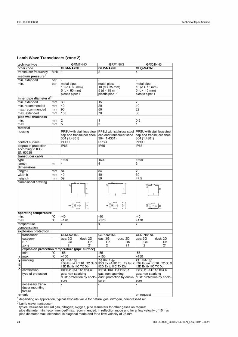
Lamb Wave Transducers (zone 2)technical type GRG1NH3 GRH1NH3 GRK1NH3order code GLG-NA2NL GLH-NA2NL GLK-NA2NLtransducer frequency MHz 0.2 0.3 0.5medium pressure1
min. extended bar metal pipe: 10 metal pipe: 10 metal pipe:10 (d > 120 mm)5 (d < 120 mm)
min. bar metal pipe: 15plastic pipe: 1
metal pipe: 15plastic pipe: 1
metal pipe:15 (d > 120 mm)10 (d < 120 mm)plastic pipe: 1
inner pipe diameter d2
min. extended mm 190 120 60min. recommended mm 220 140 80max. recommended mm 900 600 300max. extended mm 1600 1000 500pipe wall thicknessmin. mm 11 7 4max. mm 23 15 9materialhousing PPSU with stainless steel
cap and transducer shoe 304 (1.4301)
PPSU with stainless steel cap and transducer shoe 304 (1.4301)
PPSU with stainless steel cap and transducer shoe 304 (1.4301)
contact surface PPSU PPSU PPSUdegree of protection according to IEC/EN 60529
IP65 IP65 IP65
transducer cabletype 1699 1699 1699length m 5 5 5dimensionslength l mm 136.5 136.5 136.5width b mm 59 59 59height h mm 90.5 90.5 90.5dimensional drawing
operating temperaturemin. °C -40 -40 -40max. °C +170 +170 +170temperaturecompensation
x x x
explosion protection
ATEX
transducer GLG-NA2NL GLH-NA2NL GLK-NA2NLcategoryEPLzone
gas: 3G dust: 2D Gc Db 2 21
gas: 3G dust: 2D Gc Db 2 21
gas: 3G dust: 2D Gc Db 2 21
explosion protection temperature (pipe surface)min. °C -55 -55 -55max. °C +150 +150 +150marking 0637
II3G Ex nA IIC T6...T2 Gc XII2D Ex tb IIIC TX Db
0637 II3G Ex nA IIC T6...T2 Gc XII2D Ex tb IIIC TX Db
0637 II3G Ex nA IIC T6...T2 Gc XII2D Ex tb IIIC TX Db
certification IBExU10ATEX1163 X IBExU10ATEX1163 X IBExU10ATEX1163 Xtype of protection gas: non sparking
dust: protection by enclo-sure
gas: non sparkingdust: protection by enclo-sure
gas: non sparkingdust: protection by enclo-sure
necessary trans-ducer mountingfixture
- - -
1 depending on application, typical absolute value for natural gas, nitrogen, compressed air2 Lamb wave transducer:
typical values for natural gas, nitrogen, oxygen, pipe diameters for other gases on requestpipe diameter min. recommended/max. recommended: in reflection mode and for a flow velocity of 15 m/spipe diameter max. extended: in diagonal mode and for a flow velocity of 25 m/s
l
hb
l
hb
l
hb
24 TSFLUXUS_G608V1-4-1EN_Leu, 2011-03-11
FLUXUS® G608 Technical Specification
Lamb Wave Transducers (zone 2)
technical type GRM1NH3 GRP1NH3 GRQ1NH3order code GLM-NA2NL GLP-NA2NL GLQ-NA2NLtransducer frequency MHz 1 2 4
medium pressure1
min. extended bar - - -min. bar metal pipe:
10 (d > 60 mm)5 (d < 60 mm)plastic pipe: 1
metal pipe:10 (d > 35 mm)5 (d < 35 mm)plastic pipe: 1
metal pipe:10 (d > 15 mm)5 (d < 15 mm)plastic pipe: 1
inner pipe diameter d2
min. extended mm 30 15 7min. recommended mm 40 20 10max. recommended mm 90 50 22max. extended mm 150 70 35pipe wall thicknessmin. mm 2 1 0.5max. mm 5 3 1materialhousing PPSU with stainless steel
cap and transducer shoe 304 (1.4301)
PPSU with stainless steel cap and transducer shoe 304 (1.4301)
PPSU with stainless steel cap and transducer shoe 304 (1.4301)
contact surface PPSU PPSU PPSUdegree of protection according to IEC/EN 60529
IP65 IP65 IP65
transducer cabletype 1699 1699 1699length m 4 4 3dimensionslength l mm 84 84 70width b mm 40 40 30height h mm 59 59 47.5dimensional drawing
operating temperaturemin. °C -40 -40 -40max. °C +170 +170 +170temperaturecompensation
x x x
explosion protection
ATEX
transducer GLM-NA1NL GLP-NA1NL GLQ-NA1NLcategoryEPLzone
gas: 3G dust: 2DGc Db2 21
gas: 3G dust: 2D Gc Db 2 21
gas: 3G dust: 2D Gc Db 2 21
explosion protection temperature (pipe surface)min. °C -55 -55 -55max. °C +150 +150 +150marking 0637
II3G Ex nA IIC T6...T2 Gc XII2D Ex tb IIIC TX Db
0637 II3G Ex nA IIC T6...T2 Gc XII2D Ex tb IIIC TX Db
0637 II3G Ex nA IIC T6...T2 Gc XII2D Ex tb IIIC TX Db
certification IBExU10ATEX1163 X IBExU10ATEX1163 X IBExU10ATEX1163 Xtype of protection gas: non sparking
dust: protection by enclo-sure
gas: non sparkingdust: protection by enclo-sure
gas: non sparkingdust: protection by enclo-sure
necessary trans-ducer mountingfixture
- - -
remark on request1 depending on application, typical absolute value for natural gas, nitrogen, compressed air2 Lamb wave transducer:
typical values for natural gas, nitrogen, oxygen, pipe diameters for other gases on requestpipe diameter min. recommended/max. recommended: in reflection mode and for a flow velocity of 15 m/spipe diameter max. extended: in diagonal mode and for a flow velocity of 25 m/s
l
hb
l
hb
l
hb

TSFLUXUS_G608V1-4-1EN_Leu, 2011-03-11 25
Technical Specification FLUXUS® G608
Transducer Mounting Fixture
Order Code
1, 2 3 4 5 6 7...9 no. of character
tra
nsdu
cer
mou
ntin
g fix
ture
tra
nsdu
cer
- mea
surin
g m
ode
size
- fixat
ion
oute
r pi
pe
dia
me-
ter
description
VP portable Variofix
A all transducers
D reflection mode or diagonal mode
R reflection mode
M medium
C chains
N without fixation
055 10...550 mm
example
VP A - D M - C 055 portable Variofix and chains
- -
portable Variofix VP and chains
material: stainless steel 304 (1.4301), 301 (1.4310), 303 (1.4305)
dimensions:414 x 94 x 76 mm
chain length: 2 m

26 TSFLUXUS_G608V1-4-1EN_Leu, 2011-03-11
FLUXUS® G608 Technical Specification
Coupling Materials for Transducers
Technical Data
normal temperature range(4th character oftransducer order code = N)
normal temperature range(4th character oftransducer order code = E)
< 100 °C 100...170 °C < 150 °C 150...200 °C< 2 h coupling compound
type Ncoupling compoundtype E
coupling compoundtype E
coupling compoundtype E or H
< 24 h coupling compoundtype N
coupling compoundtype E
coupling compoundtype E
coupling foiltype VT
type Order Code operating temperature
material remark
°Ccoupling compound type N
990739-1 -30...+130 mineral grease paste
coupling compound type E
990739-2 -30...+200 silicone paste
coupling compound type H
990739-3 -30...+250 fluoropolymer paste
coupling foil type VT 990739-0 -10...+150,short-time peak max. 200
fluoroelastomer for transducers with transducer frequency G, H, K
990739-6 for shear wave transducers with transducer frequency M, P
990739-14 for shear wave transducers IP68 and Lambwave transducers with transducer frequency M, P
990739-15 for shear wave transducers with transducer frequency Q
990739-5 for Lambwave transducers with transducer frequency Q

TSFLUXUS_G608V1-4-1EN_Leu, 2011-03-11 27
Technical Specification FLUXUS® G608
Connection Systems
x, y - transducer cable length
l - max. length of extension cable
Transducer Cable
Technical Data
connection system NL
transducer frequency(3d character of
transducer order code)
G, H, K M, P Q S
NL
x y l x y l x y l x y lcable length m 2 3 ≤ 10 2 2 ≤ 10 2 1 ≤ 10 1 1 ≤ 10
cable length (option LC) m 2 7 ≤ 10 7 2 ≤ 10 8 1 ≤ 10 - - -
transducer cable extension cabletype 1699 6111 1750standard length m see table above see table above 5
10operating temperature °C -55...+200 -100...+225 < 80sheathmaterial stainless steel 304 (1.4301) stainless steel 304 (1.4301) stainless steel 304 (1.4301)outer diameter mm 8 8 9cable jacketmaterial PTFE PFA PEouter diameter mm 2.9 2.7 6thickness mm 0.3 0.5 0.5color brown white blackshield x x x
tran
smitt
er
l x y

28 TSFLUXUS_G608V1-4-1EN_Leu, 2011-03-11
FLUXUS® G608 Technical Specification
Damping Mats (optional)Damping mats will be used for the gas measurement to reduce acoustic noise influences on the measure-ment.
Transducer damping mats will be installed below the transducers.
Pipe damping mats will be installed at reflection points, e.g. flange, weld.
Selection of Damping Mats
type description outer pipe diameter
dimensionsl x b x h
transducer fre-quency
techni-cal type
operating temperature
remark
mm mm G H K M P °Ctransducer damping matD for temporary installation
(multiple use), fixed with coupling compound
< 80 450 x 115 x 0.5 - - - x x D20S3 -25...+60≥ 80 900 x 230 x 0.5 - - x x - D20S2
900 x 230 x 1.3 x x - - - D50S2pipe damping matA for temporary installation
(multiple use), fixed with coupling compound
< 300 300 x 115 x 0.5 x x x x x A20S4 -25...+60 for quantity see table below
B self-adhesive ≥ 300 l x 100 x 0.9 x x x x x B35R2 -35...+50 l - see table below
Quantity for Pipe Damping Mat - type A(depending on the outer pipe diameter)
outer pipe diameter D transducer frequencymm G, H K, M, P
100 12 6200 24 12300 32 16
Length of Pipe Damping Mat - type B(length l depending on transducer frequency and outer pipe diameter)
outer pipe diameter D transducer frequencyG, H K, M, P
mm mm mm300 12 6500 32 161000 126 63
b
lD
transducer damping mat pipe damping mat
reflection modediagonal mode
D - outer pipe diameter
reflection point

TSFLUXUS_G608V1-4-1EN_Leu, 2011-03-11 29
Technical Specification FLUXUS® G608
Clamp-on Temperature Probe (optional)
Technical Data
Connection
Temperature Probe
Connector
Cable
order code 670415-1 670414-1 670415-2 670414-2design short response timetype Pt100 Pt100 matched according
to DIN 1434-1Pt100 Pt100 matched according
to DIN 1434-1connection 4-wire 4-wiremeasuring range °C -30...+250 -50...+250
accuracy T ±(0.15 °C + 2 . 10-3 . T [°C]), class A ±(0.15 °C + 2 . 10-3 . T [°C]), class Aaccuracy ΔT - ≤ 0.1 K
(3K < ΔT < 6 K), more corresponding to EN 1434-1
- ≤ 0.1 K(3K < ΔT < 6 K), more corresponding to EN 1434-1
response time s 50 8housing aluminum PEEK, stainless steel 304 (1.4301), copperdegree of protection according to IEC/EN 60529
IP66 IP66
weight (without con-nector)
kg 0.25 0.5 0.32 0.64
fixation clamp-on clamp-onaccessories - plastic protection plate,
insulation foamdimensionslength l mm 15 14width b mm 15 30height h mm 20 27dimensional drawing A A B
pin cable of temperature probe extension cable1 white/blue blue2 red/blue gray3, 4, 5 not connected6 red red7 white white8 not connected
cable of temperature probe extension cable
type 4 x 0.25 mm2 black or white LIYCY 8 x 0.14 mm2 graystandard length m 3 5/10max. length m - on requestcable jacket PTFE PVC
h
l
extension cable
h
l
A
B
red/blue red white/blue white

30 TSFLUXUS_G608V1-4-1EN_Leu, 2011-03-11
FLUXUS® G608 Technical Specification
FLEXIM GmbH
Wolfener Str. 36
12681 Berlin
Germany
Tel.: +49 (30) 93 66 76 60
Fax: +49 (30) 93 66 76 80
internet: www.flexim.com
e-mail: [email protected]
Subject to change without notification. Errors excepted.
FLUXUS® is a registered trademark of FLEXIM GmbH.