Flexible Process Notations for Cross-organizational … University of Copenhagen Ph.D. Dissertation...
276
IT University of Copenhagen Ph.D. Dissertation Flexible Process Notations for Cross-organizational Case Management Systems Author: Tijs Slaats Supervisor: Dr. Thomas T. Hildebrandt Co-supervisor: Dr. Marco Carbone Evaluation Committee: Dr. Wil van der Aalst Eindhoven University of Technology, The Netherlands Dr. Hagen V¨olzer IBM Research - Zurich, Switzerland Dr. Andrzej Wasowski IT University of Copenhagen, Denmark January 2015
-
Upload
truongnhan -
Category
Documents
-
view
220 -
download
0
Transcript of Flexible Process Notations for Cross-organizational … University of Copenhagen Ph.D. Dissertation...
IT University of Copenhagen
Ph.D. Dissertation
Flexible Process Notationsfor Cross-organizational
Case Management Systems
Author:Tijs Slaats
Supervisor:Dr. Thomas T. Hildebrandt
Co-supervisor:Dr. Marco Carbone
Evaluation Committee:
Dr. Wil van der Aalst Eindhoven University of Technology,The Netherlands
Dr. Hagen Volzer IBM Research - Zurich, SwitzerlandDr. Andrzej Wasowski IT University of Copenhagen, Denmark
January 2015
Abstract
In recent times western economies have become increasingly focussed on knowl-edge work. Knowledge work processes depend heavily on the expert knowledgeof workers and therefore tend to require more flexibility then the processes seenin traditional production work. Over-constrained processes cause frustrationand inefficiency because they do not allow workers to use their expert experi-ence to make the best judgements on how to solve the unique challenges they arefaced with. However some structuring of their work is still required to ensurethat laws and business rules are being followed.
IT Systems for process control have a large role to play in structuring andorganizing such processes, however most of these systems have been developedwith a focus on production work and fail to support the more flexible processesrequired by knowledge workers. The problem arises at the core of these systems:the notations in which the processes are defined. Traditional process notationsare flow-based: control of the process flows from one activity to the next. Thisparadigm inherently encourages modellers to think in terms of strict orderingsinstead of supporting flexibility. Flow-based models that do try to capture alarge degree of flexibility tend to turn into so-called ”spaghetti models”, becauseall possible paths through the process need to be modelled explicitly. Over thelast decade new, more flexible, process notations have been researched by usinga constraint-based paradigm, where one directly models the rules of a process.
Dynamic Condition Response (DCR) Graphs, which have been developed atthe process and systems models group at IT University of Copenhagen (ITU),are one such notation. They stand apart from other constraint-based notationsby having a small set of 4 basic constraints, yet offering the full formal expres-siveness of both regular and ω-regular languages. They also offer an operationalsemantics based on transformations of markings, which means that the notationcan represent a process at both design- and runtime, facilitating easy reasoningabout the execution of the process and techniques for runtime adaptation.
This dissertation reports on the results of the Technologies for Flexible Cross-organizational Case Management Systems (FLExCMS) research project whichwas started in cooperation between ITU and the company Exformatics A/S. Thegoals of the project were to strengthen the industrial adoption of constraint-based notations and techniques by further developing DCR Graphs to be in-dustrially applicable, with a particular focus on guaranteeing safety for cross-organizational processes. We will show how DCR Graphs have been extendedwith new dimensions such as time, data and hierarchy and we will report on thedevelopment of techniques for the safe distribution and run-time adaptation ofcross-organizational processes based on DCR Graphs. We brought this researchinto practice at Exformatics by developing tools for modelling and executingDCR Graphs and applying these tools within customer projects, we report on anumber of case studies based on these projects. Finally we report on a new an-gle of research within the Business Process Management field tentatively calledHybrid BPM Technologies, which aims to combine the advantages of both theflow- and constraint-based paradigms.
1

Acknowledgements
Some people appear to be under the impression that pursuing a PhD is a ratherlonely affair, but this has not been my personal experience. Many people haveto a greater or lesser extend contributed to the work I will present in thisdissertation and without them I would not have been where I am today.
I’d like to start by thanking my supervisor Thomas Hildebrandt, withoutwhom I might never have started out on my path as researcher: Thomas believedin my ability to work in academia long before I had much faith in myself and hasbeen a driving factor in helping me apply for funding. Throughout my projecthe has been an excellent mentor, pushing my limits on all fronts.
Morten Marquard, as the founder and proprietor of Exformatics, has per-sonally played a large part in getting my PhD project funded. In addition hehas been a great company supervisor during the project and had a large handin successfully applying the research in practice.
Raghava Rao Mukkamala has been my most prominent co-author and hasalways been a pleasure to work and attend conferences with. I hope we will getto work and travel together again in the future.
Soren Debois comes in as a close second, while we only started cooperatingin the last year of my PhD our work together has been extremely rewarding andhe made a great addition to Thomas in helping me fully understand some ofthe more foundational topics we worked on, such as process algebra and sessiontypes. In addition, his sharp wit always makes for entertaining discussions.
Michael Westergaard has been an excellent host during my stay abroad atthe Architecture of Information Systems group of Eindhoven University of Tech-nology. Working together with Michael was an interesting experience and I wassad to learn that he moved to industry.
During my stay in Eindhoven I met with Hajo Reijers and we discovered acommon interested in declarative and hybrid process technologies. I’ve stronglyenjoyed working together with Hajo and hope that we will continue our coop-eration in the near future.
Additional thanks go out to Fabrizio Maria Maggi, Marco Carbone, NobukoYoshida, Christian Stahl and Francesco Zanitti, who have also all been great towork with.
I would also like to thank Wil van der Aalst, Hagen Volzer and AndrzejWasowski for joining the assessment committee for this dissertation and takethe time to come to Copenhagen for my PhD defence.
Last, but certainly not least, my girlfriend Merete has had the patience of asaint while I worked on my PhD and I consider it a small miracle that I havenot been forbidden from further pursuing a career in academia.
Finally I would like to thank all the people that were not mentioned by name,but have been great colleagues regardless during my time at the IT University,Exformatics and my stay abroad in Eindhoven.
2

Contents
1 Introduction 51.1 Dynamic Condition Response (DCR) Graphs . . . . . . . . . . . 91.2 The Technologies for Flexible Cross-organizational Case Manage-
ment Systems Research Project . . . . . . . . . . . . . . . . . . . 141.3 Related Work . . . . . . . . . . . . . . . . . . . . . . . . . . . . . 16
2 Structure of the Dissertation 21
3 Conclusion 253.1 Industrial Results . . . . . . . . . . . . . . . . . . . . . . . . . . . 263.2 Future Work . . . . . . . . . . . . . . . . . . . . . . . . . . . . . 28
List of Publications 30
References 32
4 Hierarchical Dynamic Condition Response Graphs 394.1 Nested Dynamic Condition Response Graphs . . . . . . . . . . . 404.2 Designing a Cross-organizational Case Management System using
Dynamic Condition Response Graphs . . . . . . . . . . . . . . . 484.3 Hierarchical Declarative Modelling with Refinement and Sub-
processes . . . . . . . . . . . . . . . . . . . . . . . . . . . . . . . 584.4 A Case for Declarative Process Modelling: Agile Development of
a Grant Application System . . . . . . . . . . . . . . . . . . . . . 74
5 Dynamic Condition Response Graphs with Time and Data 825.1 Contracts for Cross-organizational Workflows as Timed Dynamic
Condition Response Graphs . . . . . . . . . . . . . . . . . . . . . 835.2 Exformatics Declarative Case Management Workflows as DCR
Graphs . . . . . . . . . . . . . . . . . . . . . . . . . . . . . . . . . 132
6 Safe Cross-Organizational Flexible Processes 1486.1 Safe Distribution of Declarative Processes . . . . . . . . . . . . . 1496.2 Declarative Modelling and Safe Distribution of Healthcare Work-
flows . . . . . . . . . . . . . . . . . . . . . . . . . . . . . . . . . . 1656.3 Live Sessions with Responses . . . . . . . . . . . . . . . . . . . . 1836.4 Type Checking Liveness for Collaborative Processes with Bounded
and Unbounded Recursion . . . . . . . . . . . . . . . . . . . . . . 186
7 Safe Runtime Adaptation of Flexible Processes 2017.1 Towards Trustworthy Adaptive Case Management with Dynamic
Condition Response Graphs . . . . . . . . . . . . . . . . . . . . . 2027.2 Modular Context-Sensitive and Aspect-Oriented Processes with
Dynamic Condition Response Graphs . . . . . . . . . . . . . . . 212
3

7.3 Towards a Foundation for Modular Run-time Adaptable Process-Aware Information Systems? . . . . . . . . . . . . . . . . . . . . 218
8 Hybrid BPM Technologies 2438.1 Declarative Modeling – An Academic Dream or the Future for
BPM? . . . . . . . . . . . . . . . . . . . . . . . . . . . . . . . . . 2448.2 Mixing Paradigms for More Comprehensible Models . . . . . . . 2608.3 The Automated Discovery of Hybrid Processes . . . . . . . . . . 268
4

1 Introduction
Over the last few decades the focus of western economies has steadily shiftedfrom production work to so-called knowledge work [10, 5]. Production worktends to be highly structured, take for example a car manufacturing factory: thework is typically done along an assembly line and while there may be a certainamount of variability (the colour of the cars, materials used in the interior,additional features, etc), these variations in the production process tend to bewell-defined. Processes in knowledge industries on the other hand tend to bemuch less rigid: for example legal cases may often share similarities but arerarely exactly the same and the lawyers handling such cases typically have thefreedom to make their own decisions in how to handle the various challengeseach case presents. Knowledge workers therefore require a new level of flexibilityin their work processes [44, 62, 36]: they have strong insights into what the bestsolution to a problem is and are not helped by being constrained to a standardsolution aimed at a generic version of the problem which does not take intoaccount the unique challenges for the specific case they are working on. At thesame time some structuring of their work is still required: there may be (legalor business) rules that need to be followed in all cases and these can constrainthe ways they are allowed to approach their work.
Within the field of computer science we can employ formal methods to en-sure that the software systems developed for process support strictly follow therules specified for them. This is achieved by modelling both the behaviour ofthese systems and the rules as mathematical constructs and then using verifica-tion techniques such as state-space exploration and syntax checking to ensurethat they follow the rules and do not contain any errors (bugs). If a soundmapping exists from the notations used to describe the processes and rules tosuch mathematical constructs then verification of the models can be automatedwithout the risk of human translation error. Additionally, if the models of theprocess are directly executable by the workflow system then the running pro-cesses can be guaranteed to be correct (assuming that no mistakes were madein the specification of the rules).
Most state-of-the-art process and workflow systems have been developedwith a focus on production work and fail to support the more flexible workprocesses that knowledge workers require. The problem arises at the core ofthese systems: the notations in which processes and workflows are defined.Traditional workflow notations are grounded in the concept of flow: controlof the process progresses from one activity to the next. For example in thecase of the car manufacturing factory, the main process will describe in discretesteps how the components of a car are put together along the assembly line.Depending on the features selected for the specific car some of the steps may beskipped, or a choice between different optional components may be made, butthe overall process will always follow the same ordering in which the componentsare put together.
One such flow-based workflow notation is the Business Process Model andNotation (BPMN) [39, 61] which is considered the industry standard within
5
the field of Business Process Management [64, 54] and being maintained bythe Object Management Group. We will exemplify what a BPMN model lookslike by using the process of writing this dissertation as a running example. Werecognize that this is mostly a toy example, but found it useful for illustratingthese concepts succinctly. For more realistic examples taken from industry werefer to the papers within this dissertation, in particular 4.2, 4.4 and 6.2.
Many of the main concepts underlying BPMN are shared with other nota-tions such as flowcharts and UML activity diagrams [12] and therefore most ofthe observations made in the following paragraphs can be generalized to theseother flow-based notations.
Start
Select Papers
WriteIntroductionand Related
Work
WriteConlcusion and
Future WorkWrite Abstract
End
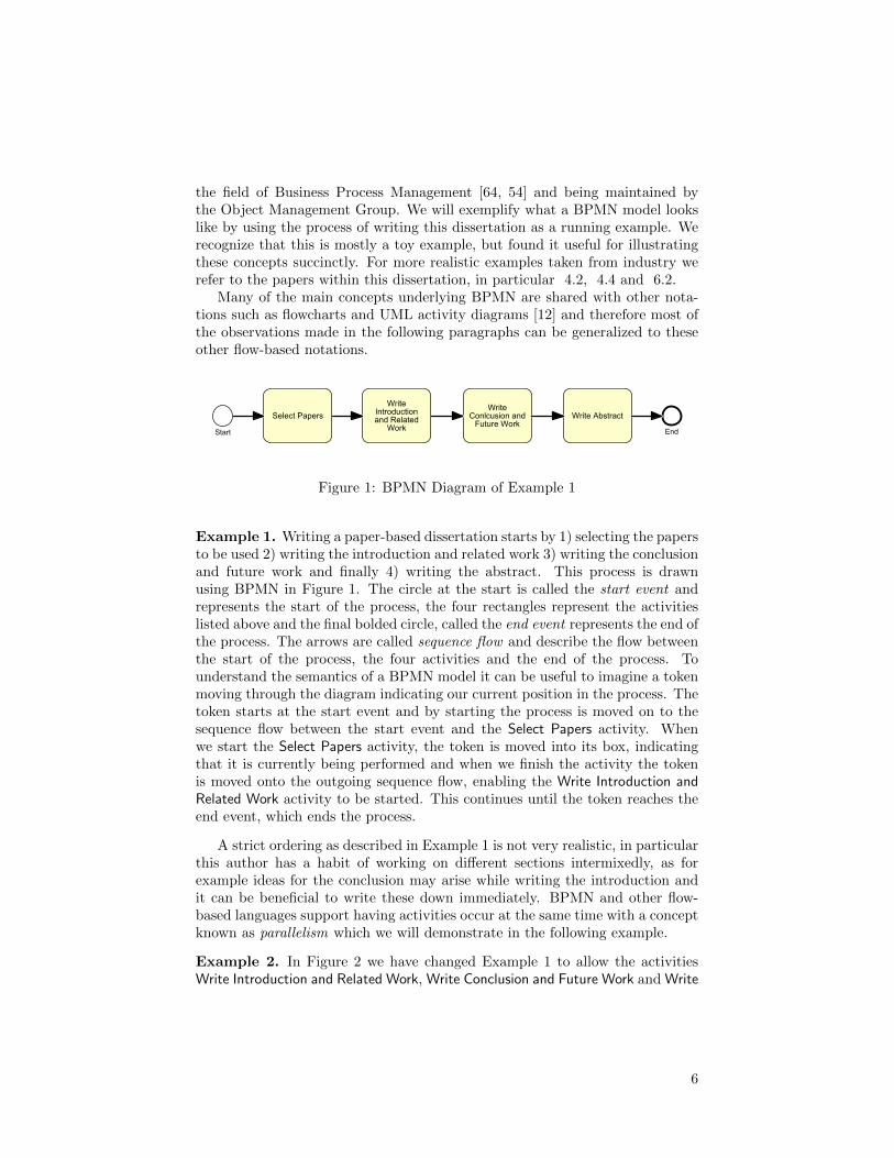
Figure 1: BPMN Diagram of Example 1
Example 1. Writing a paper-based dissertation starts by 1) selecting the papersto be used 2) writing the introduction and related work 3) writing the conclusionand future work and finally 4) writing the abstract. This process is drawnusing BPMN in Figure 1. The circle at the start is called the start event andrepresents the start of the process, the four rectangles represent the activitieslisted above and the final bolded circle, called the end event represents the end ofthe process. The arrows are called sequence flow and describe the flow betweenthe start of the process, the four activities and the end of the process. Tounderstand the semantics of a BPMN model it can be useful to imagine a tokenmoving through the diagram indicating our current position in the process. Thetoken starts at the start event and by starting the process is moved on to thesequence flow between the start event and the Select Papers activity. Whenwe start the Select Papers activity, the token is moved into its box, indicatingthat it is currently being performed and when we finish the activity the tokenis moved onto the outgoing sequence flow, enabling the Write Introduction andRelated Work activity to be started. This continues until the token reaches theend event, which ends the process.
A strict ordering as described in Example 1 is not very realistic, in particularthis author has a habit of working on different sections intermixedly, as forexample ideas for the conclusion may arise while writing the introduction andit can be beneficial to write these down immediately. BPMN and other flow-based languages support having activities occur at the same time with a conceptknown as parallelism which we will demonstrate in the following example.
Example 2. In Figure 2 we have changed Example 1 to allow the activitiesWrite Introduction and Related Work, Write Conclusion and Future Work and Write
6

Start
Select Papers
WriteIntroductionand Related
Work
WriteConlcusion and
Future Work
Write Abstract
End
Figure 2: BPMN Diagram of Example 2
Abstract to occur at the same time. To do so we use the parallel split gateway,drawn as a diamond with a plus sign inside which, using the token-based seman-tics introduced in the previous example, takes a token on the incoming sequenceflow and places an outgoing token on every outgoing sequence flow, enabling allthree activities at the same time. We can now move any of the three createdtokens as we see fit, doing these activities in any order (or even truly concurrentby doing them at the same time). All the activities lead into a parallel joingateway, which takes a token on each incoming sequence flow and places a to-ken on the single outgoing sequence flow, thereby guaranteeing that the processcan not end before all activities have completed. Note that the split and joingateways use the same symbol but can be distinguished by the fact that thesplit gateway has one incoming and multiple outgoing sequence flows, whereasthe join gateway has multiple incoming and only one outgoing sequence flow.
While the preceding example gives a good abstract view of the process, itmakes a somewhat unrealistic assumption that we know exactly when we aredone writing each section of the dissertation. If one was to directly implementthe process in an IT system then each activity could occur only once and whenit was closed, it could not be reopened. This would force users to be very care-ful about closing an activity, ie, if the author of this dissertation first finishedwriting the introduction and closed that activity, then did more work on theconclusion and realised some possible improvements on the introduction, theprocess as given above would not allow him to make these changes. A real userof such a system would likely learn this limitation and always choose to leaveactivities open until all can be closed together, but this would be a work-aroundfor a flaw in the process description and instead it is preferable to extend theprocess model to allow for repetition of these activities. This can be accom-plished in flow-based languages by using decision points and loops as we will
7

demonstrate in the following example.
Start
Select Papers
WriteIntroductionand Related
Work
WriteConlcusion and
Future Work
Write Abstract
End
repeat?
repeat?
repeat?
Decide toRepeat or Finish
Decide toRepeat or Finish
Decide toRepeat or Finish
no
no
no
yes
yes
yes
Figure 3: BPMN Diagram of Example 3
Example 3. In Figure 3 We extend Example 2 and allow the activities WriteIntroduction and Related Work, Write Conclusion and Future Work and Write Ab-stract to be repeated by using the exclusive (XOR) gateway construct. Exclusivegateways are similar to parallel gateways in that they denote a point where thecontrol splits into different paths and a join where different control paths mergeback together, however, whereas in the case of the parallel gateway control con-tinues on each path, in the case of the exclusive gate way control continues onlyon one of the possible paths. Which path is taken is based on a condition at-tached to the gateway. Within BPMN these conditions must be data-based, soif one wants to model a split based on a user decisions then making that decisionmust be modelled explicitly as an activity before the gateway. In the case ofFigure 3 this means for example that when we end the activity Write Introduc-tion and Related Work, we first have an additional activity where we decide if wewant to work more on the introduction or finish the dissertation. Typically onewill leave this activity open as long as one has not decided to either repeat orfinish. After the new activity the token moves into an exclusive gateway withthe condition ”repeat?”, it is assumed that the data necessary to evaluate thecondition is provided by the preceding activities. If we chose ”yes” the tokenmoves back to exclusive join gateway before the Write Introduction and RelatedWork activity and we can repeat it, if we choose ”no”, the token moves on tothe parallel join gateway and once all tokens arrive here we can end the process.
As we illustrated in Example 1-3, flow-based notations such as BPMN arenot particularly well-suited for describing more flexible processes. The firstproblem we encountered was that because these notations inherently require one
8

to think in terms of a strict ordering enforced by a notion of flow, a process willoften be modelled more rigidly then is required in reality. Secondly, when we doremember to make a flexible model, as in Example 3, we can see that the requirednumber of visual elements in the model starts to grow disproportional to thesimple process we are trying to describe. This happens because all the possiblepaths need to be modelled explicitly. While the example process is relativelysmall and still understandable, for larger flexible processes this often means thatthe model turns into a so-called spaghetti model and becomes unreadable.
Over the last decade there have been a number of research initiatives todevelop notations to support such flexible processes[40, 47, 17, 38, 20], usu-ally by grounding the work in a constraint- instead of flow-based paradigm.In a constraint-based notation one does not model flow, but instead directlydescribes the rules of the process such as ”we need to select papers before wecan perform other activities” and ”every activity needs to be performed at leastonce”. It is then up to the workflow system to determine all possible actionsfor the user and allow him the freedom to make his own decisions as long asthey fall within the rules (optionally suggesting best-practice solutions, but notenforcing them). Within academia constraint-based notations are commonlycalled declarative notations, whereas flow-based notations are often referred toas imperative or procedural notations, a practice stemming from an originalcomparison to declarative (functional) and imperative (procedural) program-ming languages. Within the papers of this dissertation we primarily use theterms declarative and imperative to refer to respectively constraint-based andflow-based notations.
1.1 Dynamic Condition Response (DCR) Graphs
One such declarative notation called Dynamic Condition Response (DCR) Graphs[17, 35] was developed at the IT University of Copenhagen by Thomas T. Hilde-brandt and Raghava Rao Mukkamala as a part of the TrustCare project1 andthe latter’s dissertation [34]. DCR Graphs are a generalization of Event Struc-tures [37, 65, 66, 67, 59] and consist of events (which can be used to model bothactivities and BPMN events such as timers), a marking over the events andfour possible relations between these events. When not constrained (throughrelations or the marking) events can be executed at any time and any numberof times.
The marking of a DCR Graph keeps track of 1) which events have beenexecuted (at least once), 2) which events are still required to be done (oftenreferred to as being pending) and 3) which events are currently included. Eventscan only be executed if they are included and are also only considered relevantto the process while they are included, this in particular means that while anevent is excluded (not included), we can disregard if it is required. This tiesinto the accepting condition of a DCR Graph which determines when exactly a
1Trustworthy Pervasive Healthcare Processes (TrustCare) Research Project - http://www.trustcare.dk/
9

process is allowed to end: we can finish executing a DCR Graph whenever thereare no events that are both included and required. There is no default initialmarking for a DCR Graph, this means that it is for example possible to havecertain events be initially required, in essence modelling a to-do list at the startof the process.
The relations describe how events constrain each other and effect the mark-ing: the condition relation states than one event can not be executed beforeanother event is executed (unless the latter event is excluded), the response re-lation states that doing one event makes another event required (i.e. doing oneactivity adds another activity to the list of things that need to be done before wecan end our process) and finally the dynamic exclusion and dynamic inclusionrelations respectively remove and add events back into the workflow. We willnow show how the process from Example 3 can be modelled as a DCR Graph.
Figure 4: DCR Graph of the process in Example 3
Example 4. The DCR Graph in Figure 4 represents the same process as inFigure 3. Similar to BPMN, the boxes represent events(activities). The ear ofthe box is reserved for adding roles to the activities, but these are not used in thecurrent example. The relations are drawn as arrows between the events. Thered arrow with a percentage sign at the end denotes the exclude relation, in this
10
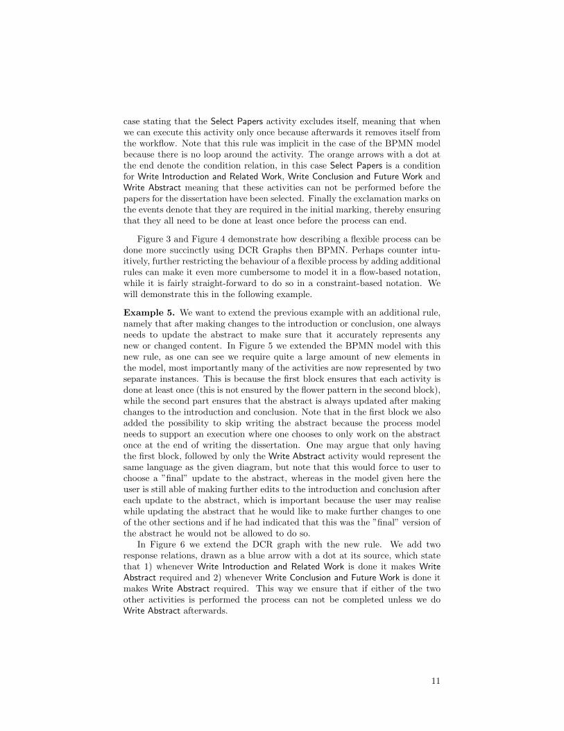
case stating that the Select Papers activity excludes itself, meaning that whenwe can execute this activity only once because afterwards it removes itself fromthe workflow. Note that this rule was implicit in the case of the BPMN modelbecause there is no loop around the activity. The orange arrows with a dot atthe end denote the condition relation, in this case Select Papers is a conditionfor Write Introduction and Related Work, Write Conclusion and Future Work andWrite Abstract meaning that these activities can not be performed before thepapers for the dissertation have been selected. Finally the exclamation marks onthe events denote that they are required in the initial marking, thereby ensuringthat they all need to be done at least once before the process can end.
Figure 3 and Figure 4 demonstrate how describing a flexible process can bedone more succinctly using DCR Graphs then BPMN. Perhaps counter intu-itively, further restricting the behaviour of a flexible process by adding additionalrules can make it even more cumbersome to model it in a flow-based notation,while it is fairly straight-forward to do so in a constraint-based notation. Wewill demonstrate this in the following example.
Example 5. We want to extend the previous example with an additional rule,namely that after making changes to the introduction or conclusion, one alwaysneeds to update the abstract to make sure that it accurately represents anynew or changed content. In Figure 5 we extended the BPMN model with thisnew rule, as one can see we require quite a large amount of new elements inthe model, most importantly many of the activities are now represented by twoseparate instances. This is because the first block ensures that each activity isdone at least once (this is not ensured by the flower pattern in the second block),while the second part ensures that the abstract is always updated after makingchanges to the introduction and conclusion. Note that in the first block we alsoadded the possibility to skip writing the abstract because the process modelneeds to support an execution where one chooses to only work on the abstractonce at the end of writing the dissertation. One may argue that only havingthe first block, followed by only the Write Abstract activity would represent thesame language as the given diagram, but note that this would force to user tochoose a ”final” update to the abstract, whereas in the model given here theuser is still able of making further edits to the introduction and conclusion aftereach update to the abstract, which is important because the user may realisewhile updating the abstract that he would like to make further changes to oneof the other sections and if he had indicated that this was the ”final” version ofthe abstract he would not be allowed to do so.
In Figure 6 we extend the DCR graph with the new rule. We add tworesponse relations, drawn as a blue arrow with a dot at its source, which statethat 1) whenever Write Introduction and Related Work is done it makes WriteAbstract required and 2) whenever Write Conclusion and Future Work is done itmakes Write Abstract required. This way we ensure that if either of the twoother activities is performed the process can not be completed unless we doWrite Abstract afterwards.
11

Start
SelectyPapers
WriteIntroductionandyRelated
Work
WriteConlcusionyand
FutureyWork
WriteyAbstract
End
repeat?
repeat?
repeat?Skip?
WriteIntroductionandyRelated
Work
WriteConlcusionyand
FutureyWork
Workyon?
WriteyAbstract
Finish?
DecideytoRepeatyoryFinish
DecideytoRepeatyoryFinish
DecideytoRepeatyoryFinish
DecideytoySkipWriting
Abstract
DecideyonynextActivity
DecideytoFinishyorContinue
no
no
yes
yes
yes
no no
yes
conclusion
intr
oduc
tion
abstract
yes
no
Figure 5: BPMN Diagram of the process in Example 5
12
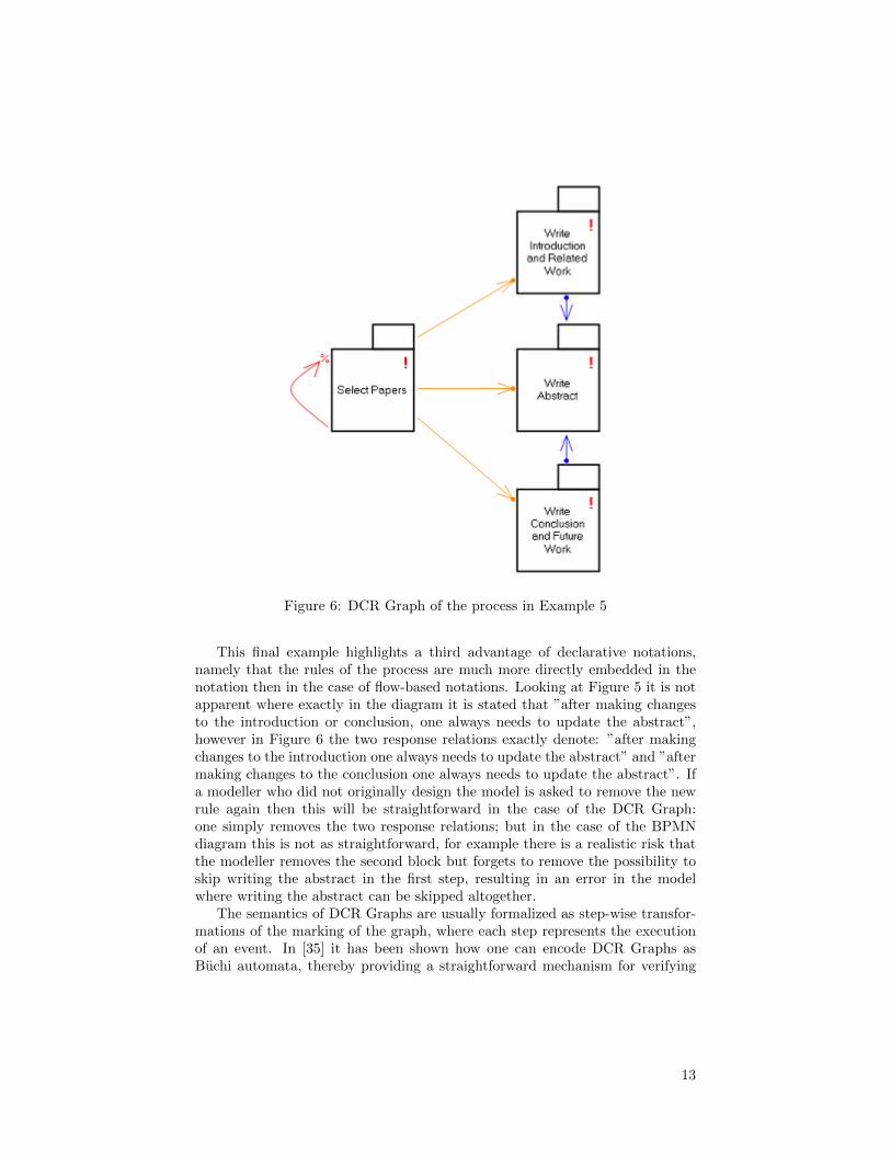
Figure 6: DCR Graph of the process in Example 5
This final example highlights a third advantage of declarative notations,namely that the rules of the process are much more directly embedded in thenotation then in the case of flow-based notations. Looking at Figure 5 it is notapparent where exactly in the diagram it is stated that ”after making changesto the introduction or conclusion, one always needs to update the abstract”,however in Figure 6 the two response relations exactly denote: ”after makingchanges to the introduction one always needs to update the abstract” and ”aftermaking changes to the conclusion one always needs to update the abstract”. Ifa modeller who did not originally design the model is asked to remove the newrule again then this will be straightforward in the case of the DCR Graph:one simply removes the two response relations; but in the case of the BPMNdiagram this is not as straightforward, for example there is a realistic risk thatthe modeller removes the second block but forgets to remove the possibility toskip writing the abstract in the first step, resulting in an error in the modelwhere writing the abstract can be skipped altogether.
The semantics of DCR Graphs are usually formalized as step-wise transfor-mations of the marking of the graph, where each step represents the executionof an event. In [35] it has been shown how one can encode DCR Graphs asBuchi automata, thereby providing a straightforward mechanism for verifying
13

them for deadlock, livelock and non-emptiness of their language. In [34] theauthor expanded on this work by proposing a new verification technique em-ploying the SPIN model checker. In addition it has been shown [34] that theformal expressive power of DCR Graphs is exactly that of the union of regularand omega-regular languages.
1.2 The Technologies for Flexible Cross-organizational CaseManagement Systems Research Project
While a number of declarative notations and techniques have been developedwithin academia, this research has not really been adopted by industry yet. Dif-ferent reasons for this have been suggested [14, 69], in particular the paradigmchange from flow- to constraint-based notations not only requires modellers tolearn new notations, but also change the way they think about modelling pro-cesses. Instead of describing possible process flows as they are used to, they needto learn to specify the constraints and rules of their processes. Secondly declar-ative notations and techniques are still relatively immature when compared toimperative notations and techniques, for example research on extensions such ashierarchy, time and data is abundant in the imperative world but rather sparsein the declarative community.
In 2011 we began to cooperate with Exformatics A/S, a Danish softwaredeveloper providing Electronic Case Management (ECM) [58, 46] Systems toknowledge-intensive businesses and organizations in the public and private sec-tor. Exformatics shared our vision that flow-based notations did not offer ad-equate flexibility for modern ECM systems and together we carried out a casestudy with one of their customers where we used DCR Graphs to model theirprocesses (reported on in paper 4.2). Exformatics was pleased with the resultsof the case study and interested in developing tools based on DCR Graphs whilecontinuing the research cooperation in the form of an industrial PhD project.We therefore initiated the Technologies for Flexible Cross-organizational CaseManagement Systems (FLExCMS) project with the overall goal of strengthen-ing and encouraging industrial adaptation of declarative process notations andtechniques.
The research goals of the project focussed on further developing the DCRGraphs notation to be industrially applicable, with a particular focus on guaran-teeing safety for cross-organizational processes [25, 8, 15, 63]. By guaranteeingsafety we both mean ensuring that processes follow the rules, but also that therules do not give rise to classical problems such as deadlock (getting stuck in aprocess, i.e. one is able to make bad decisions after which it is impossible tomove on) or livelock (a situation in which one is still able to move in the process,but the available steps do not provide progress towards its goals). By focussingon cross-organizational processes we brought a new dimension to the work thathas not been explored for flexible processes notations before and for which theissue of safety is of particular relevance: problems such as deadlock and livelockare prevalent in distributed settings where for example it can happen that twoparties are unable to progress in their work because each party is waiting for
14

input from the other (deadlock), or two parties continually ”pass the ball” toeach other, satisfying their own local rules that require them to pass on theirwork, but never satisfying the global goal of the process (livelock).
The industrial goals of the project were to develop tools, based on the ex-tended notation and new techniques and methods, for modelling and executingflexible processes and to carry out a number of case studies with customers ofExformatics where we applied these tools and methodologies. These case studiesin turn providing feedback for the research activities.
In addition to the original project goals we investigated two more areas ofinterest. First of all we researched techniques for the safe runtime adaptationof flexible processes. Runtime adaptation of processes is particularly relevantfor long-running processes, for example the handling of mortgages by a creditinstitution, where rules and regulations can change during the lifetime of aprocess. In such cases running processes need to be adapted to the changes inthe regulations without introducing errors to the process. Different approachescan be used to ensure that adaptations are made safely, one can check for eachprocess individually if the adapted process contains the possibility for errors suchas deadlock and livelock, but one can also check formally that certain classes ofadaptations can always be made without introducing unforeseen issues.
Finally we participated in starting up a new research area within the BPMfield which we tentatively call Hybrid BPM Technologies. This new research areais founded on the observation that in reality few domains contain exclusivelystructured or flexible processes and in many cases even a single process cancontain both distinctly structured and flexible parts. For example in hospitalsthe processes handling patient care may contain both very rigid treatment plans(because they deal with potentially dangerous medicine) and much more flexibletreatment plans which leaves a lot of the decision making to the doctor so thathe may fine-tune the treatment to specific patients. There has been some workon the overlap and combination of the flow- and constraint-based paradigms [45,56] in the past, but only more recently (paper 8.1) has it been proposed thatinvestigating such hybrid approaches is a worthwhile field of research on its ownwith many open research questions.
Based on the original research goals and the new angles of work that aroseduring the project, this dissertation addresses four primary hypotheses:
1. The declarative DCR Graph model can be extended to cover all therequired aspects of flexible workflow, in particular hierarchy, deadlines(time) and data.
2. We can support safe cross-organizational flexible process models by de-veloping distribution techniques for the declarative DCR Graph notation.
3. We can support safe runtime adaptation of flexible process models bydeveloping adaptation techniques for the declarative DCR Graph notation.
15

4. Creating a bridge between the traditional imperative and new declarativenotations will allow for a) more straightforward adoption of the latterand 2) more concise and understandable hybrid models that combine thestrengths of the two paradigms.
1.3 Related Work
There is a significant overlap between this dissertation and the work presentedby Raghava Rao Mukkamala in his dissertation [34] resulting from our projectspartially running concurrently and a large degree of cooperation as we bothworked on similar topics. However, whereas Mukkamala’s main contributionwas to introduce DCR Graphs as a formal model for Declarative processes, thisdissertation’s main contribution is to extend the notation and techniques tomake them industrially applicable. In particular completely new contributionsin this dissertation (which will be introduced in more detail further on) are thework on live session types, hierarchical DCR Graphs and hybrid notations andtechniques.
Select Papers
1
Write Abstract
1..*
Write Introduction and Related Work
1..*
Write Conclusion and Future Work
1..*
Figure 7: Declare model of the process in Example 3
Declare
Declare [55, 40, 50] was the first large-scale effort within the BPM communityto create a declarative notation for business processes. In essence Declare isa template language: it consists of a fairly large number of predefined con-straints between activities which are formalized as Linear Temporal Logic(LTL)
16

formulae. The semantics of a declare model is defined as the conjunction ofthe formulae of all the constraints in the model. More recent papers have pro-posed formalizing Declare in other languages such as coloured automata [31] andSCIFF [33, 32]. Declare has gained traction in the academic BPM communityand is a commonly used notation when investigating declarative techniques [70],for example common in process mining [29], however to our knowledge there isvery little documented usage of Declare in industry. There are a number of fac-tors that set DCR Graphs apart from declare: first of all formal expressivenessresults show that DCR Graphs, using only the four basic relations, can expressexactly the union of regular and ω-regular languages. To our knowledge thereare no published results on the formal expressiveness of Declare. It is sometimesargued that one can always just add new constraint templates and therefore theexpressiveness of Declare is that of the underlying language chosen, howeverthis assumes that it is possible to add an infinite number of constraints andrequires that the modellers are able of modelling in terms of the underlyinglanguage and not just Declare. Secondly the runtime semantics of DCR Graphsare given in terms of DCR Graphs (i.e. as transformations of the marking),this benefits reasoning about DCR Graphs at runtime, allowing for reusing thedesign-time graphical notation to also visualize run-time models and easing thedevelopment of run-time adaptation techniques. The third difference is that be-cause declare models are defined as the conjunction of their constraints, addingadditional constraints to a declare model always limits the possible behaviours.This is not the case for DCR Graphs, where relations can affect each otherin ways where adding an additional relation to the model actually allows newbehaviours, which may be unexpected for inexperienced modellers and meantthat we had to develop a theory of refinement for DCR Graphs as discussed inpaper 6.4.
Figure 7 shows how example 3 can be modelled using Declare. It lookssomewhat similar to the DCR Graph, the main difference being that Declarehas cardinality constraints that can be used to state that Select Papers shouldhappen exactly once (denoted by the 1 over the activity) and that the otheractivties should happen at least once (denoted by the 1..∗ over the activity).The arrow that looks like the condition relation from DCR Graphs has a similarsemantics in Declare, but is named the precedence constraint.
Petri nets
Petri nets [41] are a graph-based formal model particularly well-suited to de-scribing distributed and concurrent systems [24] which have become a popularchoice within academia for modelling workflows [52, 57, 11]. A Petri net isa bipartite graph that consists of transitions and places, connected by directedarcs. Places represent the presence of resources (which can be for example data,documents and human resources, but also simply the fact that some activity hasbeen performed previously), whereas transitions represent activities and events.The resources themselves are represented as tokens which occupy a place whenthey are present. To fire (execute) a transition at least one token needs to be
17

Select Papers
Write Introduction and Related Work
Write Abstract
Write Conclusion and Future Work
1`()
Finish Dissertation
Figure 8: Petri net of the process in Example 3
present on each place connected to it by an incoming arc. When the transitionfires these tokens are consumed and removed from their places, in their place anew token is created in each place that is connected through an outgoing arcwith the transition. There are many variations of Petri nets, some based onlimiting the original notation to make certain decision problems easier to anal-yse [13] such as WorkFlow nets (WF-nets) [52, 1], which are aimed specificallyat modelling business processes, while others provide extensions to make themmore expressive such as Coloured Petri nets (CPN) [23, 22, 43] which add typesand values to places and tokens and guards to arcs and transitions, allowing forthe modelling of traditional data structures and value-based constraints.
Figure 8 shows how example 3 can be modelled as a Petri net. On theleft is an initial place with a single token in it (denoted by the 1‘()), executingSelect Papers removes this token and places a token in each of the followingthree places. We can now no longer execute Select Papers because there is notoken in the initial place, but we can execute all the other activities. Each ofthe other three activities will take a token from their preceding place and putit back after executing, thereby ensuring that they can be executed again anynumber of times. They will also place a token in an additional place to theirright, which counts the number of executions for each activity. To signal whenwe are done with the dissertation we added a Finish Dissertation activity. Itwill only be enabled when all activities have been done at least once and whenfiring will remove the three tokens that enable the writing activities, therebydisabling all activities and ending the process. One could do without the FinishDissertation activity if one defines an acceptance criteria for the Petri net whereany marking in which each of the three counting places on the outer right hasat least one token in it is accepting.
18

Process Mining
Process mining [53] is an emerging topic within the BPM field with the aim”to discover, monitor and improve real processes (i.e., not assumed processes)by extracting knowledge from event logs readily available in today’s (informa-tion) systems” [49]. As such it can be seen as a specialization of data miningand machine learning and indeed many process mining approaches make use ofexisting data mining and machine learning techniques, such as association rulemining [28] and inductive logic programming[4, 26]. Supported by strong inter-est from industry, where process mining techniques can be used to get insightsinto the way companies actually do their work in practice and thereby improveprocess efficiency, the topic has received increased attention in the business pro-cess management community, leading to the creation of an special task force onthe subject2. One particular area of interest in the process mining community isprocess discovery [48, 2], which concerns itself with developing algorithms thatbased on event logs attempt to build a models of the underlying processes thatcould have generated the logs. In the last few years many different process dis-covery techniques have been proposed both for flow-based models, in particularPetri nets [51, 27] and declarative models [28, 4, 26, 9, 30].
Session Types
Session types [18, 68, 60] are a behavioural typing system, meaning that theirfocus is not on typing data but instead the behaviour of processes. The goalis therefore not to guarantee type-compatibility of variables and expressions,but instead behavioural compatibility of interacting π-calculi processes. Thesession type specifies the protocol that process interactions should adhere to,usually referred to as session fidelity. Session types have the additional benefitthat well-typed processes are guaranteed to be deadlock free, which providesa means of verifying safety of processes by syntax checking instead of state-space exploration. Session types have seen many extensions, for example tomulti-party session types [19] which allow the specification of protocols withmore then two parties. It has also been proposed that session types can beused to provide a behavioural typing system for BPMN processes which involvecommunication between distributed actors modelled as choreographies [7].
Guard-Stage-Milestone model
The Guard-Stage-Milestone (GSM) model [21] developed at IBM Research isbased on the earlier work on artifact-centric business processes [3]. A GSMmodel is divided into stages which contain the atomic tasks of the model. Astage can have guards which need to be satisfied before the stage becomes activeand its tasks can be executed. A stage can also contain milestones which can beseen as the acceptance criteria of the stage, through performing the tasks of thestage the milestones can become satisfied, which can in turn be part of satisfying
2IEEE CIS Task Force on Process Mining - http://www.win.tue.nl/ieeetfpm/
19

the guards of other stages. While GSM has a distinct declarative flavour it ismainly a data-centric model. The GSM model has had a strong influence onthe development of the Case Management Model And Notation (CMMN) [38],which is a new standard notation developed by the Object Management Groupaimed in particular at case management.
20
2 Structure of the Dissertation
The body of this dissertation consists of the papers that resulted from theFlexCMS project, separated into the following five areas of interest:
Hierarchical Dynamic Condition Response Graphs
In section 4 we present four publications that deal with adding different formsof hierarchy to DCR Graphs. The papers focus on validating the first part ofhypothesis 1, by showing that indeed DCR Graphs can be successfully extendedwith a notion of hierarchy.
In Nested Dynamic Condition Response Graphs we introduce an extensionto DCR Graphs that allows for the nesting of events. Nesting in this case ismainly cosmetic: only atomic events are executable, while higher-level eventsare used to group sets of events together and relations to and from super-eventsapply to all their atomic sub-events. This can be used to make process diagramsmore succinct, for example if a process contains two phases and doing all theactivities in the first phase is a prerequisite for the activities in the secondphase, then we can use two super-events to represent the phases and draw asingle condition relation between them (instead of n × m condition relationsfor each pairing of events between the first and second phase). Another maincontribution of the paper is the milestone relation which inherently captures theaccepting condition of DCR Graphs, namely that for one event to be executableanother event needs to either not be required or be excluded. Using this relationtogether with nesting means that one can disable a phase as long as all therequired tasks in a previous phase have not been performed yet.
In the second paper, Designing a Cross-organizational Case ManagementSystem using Dynamic Condition Response Graphs, we report on a case studyperformed together with Exformatics and Landsorganisationen i Danmark (LO),an umbrella organization for trade unions in Denmark. During the case studywe used nested DCR Graphs to model the main process underlying the cross-organizational case management system aimed at handling conflicts betweenemployees and their employers that Exformatics was developing for LO.
In Hierarchical Declarative Modelling with Refinement and Sub-processes weintroduce Hierarchical Dynamic Condition Response (Hi-DCR) Graphs, whichadd a notion of dynamically spawned sub-processes to DCR Graphs. A sub-process is in itself a Hi-DCR Graph that is spawned as a side-effect to executingan event. In the sub-process we distinguish between interface and local events:interface events are merged with equally named events in the parent process,whereas local events are always copied into the main process with a new uniquename, allowing one to define multi-instance sub-processes. The spawning of asub-process is formally defined through the composition of the main graph withthe sub-process graph and the paper also identifies a class of compositions thatguarantee language-refinement, which is investigated further in paper 7.3.
The final paper A Case for Declarative Process Modelling: Agile Develop-ment of a Grant Application System reports on the development of a case man-
21
agement system for a Danish funding agency by Exformatics. The processesfor handling funding requests were modelled as DCR Graphs and these modelswere used directly as executable code within the implementation of the casemanagement system for workflow enactment. The paper has been includedin this section because the project demonstrated a clear need for support formulti-instance sub-processes and (an abstracted version of) one of the processesidentified during the case study has been used in the previous paper as a runningexample.
Dynamic Condition Response Graphs with Time and Data
In section 5 we present two publications that deal with adding time and datadimensions to DCR Graphs. The papers primarily focus on validating the secondpart of hypothesis 1, by showing how DCR Graphs can be successfully extendedwith a notion of time and data.
The first paper, Contracts for Cross-organizational Workflows as Timed Dy-namic Condition Response Graphs, is a journal publication in which we extendDCR Graphs to support discrete time deadlines. We also provide a technique forverifying safety and liveness properties through a mapping to finite state tran-sition systems. We also prove that the general technique for safe distributionof DCR Graphs provided in Paper 6.1 can be extended to timed DCR Graphs.We exemplify the use of timed DCR Graphs and the distribution technique inpractice on a timed extension of the process from paper 4.2.
In the second paper, Exformatics Declarative Case Management Workflowsas DCR Graphs, we give an informal presentation of an extension to DCRGraphs with data, show how DCR Graphs are used by Exformatics to modelworkflows through a case study of an invoice workflow and give an overviewof the tools that have been developed by Exformatics to support working withDCR Graphs. We report on the use of these tools both in commercial projectsand in a bachelor level course at ITU.
Safe Cross-Organizational Flexible Processes
In section 6 we present four publications that deal with different techniquesaimed at supporting cross-organizational processes. The papers focus on vali-dating hypothesis 2 by developing distribution techniques for DCR Graphs andlaying the foundations for bridging the work on DCR Graphs to the highlyrelevant work on session types.
In Safe Distribution of Declarative Processes we present a technique that,given a declarative global description of a process and a separation of the activ-ities of the process over collaborating actors, projects a local declarative processfor each actor that only describes the parts of the process that are relevantfor them. We show how these local processes can be safely executed in a syn-chronous distributed setting by only communicating the execution of activitiesor events, all the while adhering to the original global specification. We exem-plify the distribution technique on the process identified in the case study that
22
we reported on in paper 4.2.In Declarative Modelling and Safe Distribution of Healthcare Workflows we
present a case study based on an oncology treatment process from a Danishhospital that applies the techniques developed in the previous paper. We alsoextend the techniques from the previous paper to cover nesting and the milestonerelation as defined in paper 4.1.
In the third publication, RSVP: Live Sessions with Responses we proposeextending session types to allow for specifying liveness properties. Concretelywe do so by introducing sessions with responses, where branching and selec-tion labels can be annotated with the expected responses given in conjunctivenormal form (without negation). A process is considered live when whenever alabel is selected, one of the labels in each of the disjunctive responses is even-tually selected, similar to the response semantics of DCR Graphs. The typingsystem for guaranteeing that well-typed processes are live in this sense is giveninformally.
The fourth paper Type Checking Liveness for Collaborative Processes withBounded and Unbounded Recursion continues the work initiated in the previouspaper. Unlike the other paper we define responses as a single set of labels,however we give a formally proven sound typing system guaranteeing request-response liveness of well-typed processes and prove that the extended types arestrictly more expressive than standard session types. We apply the new typesto a process calculus similar to collaborative BPMN processes and exemplifythe use of the calculus and type system on a concrete example.
Safe Runtime Adaptation of Flexible Processes
In section 7 we present three publications that deal with different techniquesaimed at runtime adaptation of flexible processes. The papers mainly focus onvalidating hypothesis 3 by developing several approaches that can be used forthe run-time adaptation of DCR Graphs.
In Towards Trustworthy Adaptive Case Management with Dynamic Con-dition Response Graphs we discuss techniques for safe run-time adaptation ofDCR Graphs. We introduce three basic operations that can be used for adapt-ing DCR Graphs: compose, change and discard. Composition allows one toadd new events and relations to a DCR Graph by composing it with a processfragment defined as a second DCR Graph that contains exactly the events andrelations one wants to add. The change operator allows one to change the namesof events and labels. The discard operation allows one to remove events andrelations from the Graph. The composition and discard operations can also beused to modify the run-time marking of a DCR Graph. To ensure safety ofadapted DCR Graphs we show how they can be verified for deadlock freedomand liveness after adaptation.
In Modular Context-Sensitive and Aspect-Oriented Processes with DynamicCondition Response Graphs we show how DCR Graphs, supported by the tech-niques introduced in the previous paper, can be used as a formal foundation forthe modular design and implementation of context-sensitive and aspect-oriented
23
processes. We exemplify the approach with a context-sensitive authorizationprocess.
The final paper in this section Towards a Foundation for Modular Run-time Adaptable Process-Aware Information Systems? is the only draft paperin this dissertation. It is an extension of the work started in paper 4.3, buthere we instead focus on the refinement of processes through composition byintroducing the DCR Process Language, a calculus-based representation of DCRGraphs providing easier reasoning about the composition of processes. We showhow run-time adaptation can be achieved through composition and when suchadaptations can be considered safe refinements. The paper also contains formalproofs for the expressiveness results of both regular DCR Graphs and Hi-DCRGraphs.
Hybrid BPM Technologies
In section 8 we present three publications that investigate hybrid process nota-tions and techniques. The papers lay the foundations for validating hypothesis 4by 1) documenting an industrial interest in hybrid process notations, 2) propos-ing such a notation and 3) initiating work on developing relevant technologiesthat use hybrid notations.
In Declarative Modeling - An Academic Dream or the Future for BPM? wepresent a study performed at a Dutch developer of ECM software on whatpractitioners think of declarative modelling. We conclude that the practitionersinvolved in the study are receptive to the idea of a hybrid approach combiningimperative and declarative techniques, rather than making a full shift from theimperative to the declarative paradigm. Moreover, we report on requirements,use cases, limitations, and tool support of such a hybrid approach. Based onthe gained insight, we propose a research agenda for the development of thisnovel modelling approach.
In Mixing Paradigms for More Comprehensible Models we propose an ap-proach to modelling workflows that combines colored Petri nets with the declar-ative languages Declare and DCR Graphs. The combined approach makes itpossible to use both imperative and declarative constructs in a single languageand allows one to model data in both Declare and DCR Graphs. We provideconsiderations necessary for enactment and describe how the approach has beenimplemented in CPN Tools 4.
In The Automated Discovery of Hybrid Processes we introduce an algorithmfor mining hybrid process models. The approach first identifies structured andflexible parts of the log and then mines these parts separately using respectivelya declarative or flow-based miner. This results in a number of declarative and/orflow-based sub-processes which are then combined in a root process that is itselfmodelled either declarative or flow-based. The approach can be used iterativelyto generate a multi-level sub-processes hierarchy. In our implementation we useDeclare as a declarative notation and Petri nets as a flow-based notation, butthe approach does not prescribe the use of specific miners and other notationscould be used. We evaluated the approach on the BPI 2012 challenge log.
24
3 Conclusion
Overall we believe that we brought the FlexCMS project to a very success-ful conclusion. The two initial hypotheses of the project were validated by 1)developing notions of hierarchy, time and data for DCR Graphs and 2) devel-oping techniques for the safe distribution of such declarative models. The thirdhypothesis, which arose during the project, was successfully validated by de-veloping two distinct approaches for the run-time adaptation of DCR Graphs.Finally we laid a clear foundation for further investigating the usability andfeasibility of hybrid process notations. Further experimental research is neededto verify the final hypothesis, but this is not surprising as it arose closer to theend of the project and was not a part of the initial goals. More precisely weproduced valuable research results in the following areas:
We investigated two different methods for adding hierarchy to DCR Graphs,the first being Nested DCR Graphs, an extension aimed at representing complexdiagrams with fewer visual elements and thereby improving understandability ofthe models. As a part of this work we also introduced the additional milestonerelation, which has proven to be useful for modelling acceptance criteria inprocesses. While it can be proven that the relation does not make the notationformally more expressive, it is also not readily apparent how the relation canbe modelled as a pattern using only the other basic relations. The secondmethod, Hierarchical DCR (Hi-DCR) Graphs, offers a semantic extension thatadds support for multiple instance sub-processes to DCR Graphs which wasseen as an important feature by the industrial partner to model the processesthat they were encountering in practice. We believe that these two extensionstogether greatly improve the usability of DCR Graphs.
We also developed extensions for time and data, respectively supportingthe modelling of deadlines and delays/durations and the modelling of globalvariables that can be used as guards on both events and relations, satisfyingtwo more needs from industry for modelling real-life processes.
To support cross-organizational processes we researched a technique forsafely projecting a DCR Graph over sets of events. The projection techniqueensures that the projected graphs can be executed on separate platforms as longas communication between them is performed synchronously. A strong benefitof this approach is that given a global view of how the entire process shouldwork one can generate local views for the participating parties that only showthe activities that directly relate to their work, allowing for a distribution of con-cerns where the collaborators in a process do not necessarily need to be awareof the details of the other parties role in the process. We also extended thistechnique to work on Timed DCR Graphs. In addition we worked on extendingthe theory of session types with the ability of checking for liveness constraints,which enables verification of processes for safety and liveness properties basedon syntax checking instead of state space exploration. Making the mappingbetween DCR Graphs and session types is left for future work, once this hasbeen completed the approach will also allow for DCR Graphs to be combinedwith processes specified in other notations as long as their shared interfaces are
25
defined using session types.We developed two methods for run-time adaptation. The first method de-
fines a number of operators that can be used for making both incremental anddecremental changes to DCR Graphs and provides techniques for checking theadapted graphs for deadlock and livelock. The second method allows only in-cremental updates to a DCR Graph through composition, but also identifies asafe subset of adaptations that guarantee refinement of the original model. Notethat the terms incremental and decremental here are used in terms of the ele-ments (events, relations, etc.) of the DCR Graph and not the behaviour of theDCR Graph. In fact, incremental updates to a DCR Graph can both decreaseand increase the possible behaviours: one can add a new event, enabling anactivity that was not present before, or one can add an unsatisfiable conditionto an existing event, disabling an activity that was enabled before.
We also reported on a number of case studies: we showed how nested DCRGraphs have been used to model the case management system of a Danishumbrella organization of trade unions, how the projection technique can beused to safely distribute the responsibilities of different actors in the oncologyworkflow of a Danish hospital and how DCR Graphs were used by Exformatics todesign and develop a case management system to support the grant applicationprocess of a Danish foundation.
Finally we participated in opening up a new research area in the BPM fieldfocussing on Hybrid Process Technologies, which make use of both imperativeand declarative notations and techniques. In particular we set out a researchagenda for the new field, proposed how specific imperative and declarative nota-tions could be combined and investigated process discovery of hybrid processes.
We feel that these research results have made a significant contribution tothe field of declarative process modelling. To our knowledge we were the first toinvestigate techniques for supporting cross-organizational declarative processesand by extending DCR with time, data and hierarchy we enabled declarativenotations to be used for modelling more complex real-life processes. Being ableof supporting run-time adaptation has also shown to be a vital property for theindustrial partner, who regularly encounters situations where running processesneed to be adapted to the changing needs of customers. The work on hybridprocess notations and techniques arose during the project and was not plannedin advance but appears to be well received by the community with several otherresearch groups showing interest in such notations and the interplay betweendeclarative and imperative notations in general [6, 16, 42].
This dissertation has been primarily focussed on presenting the academicresults of the authors PhD project, however in the next subsection we willshortly touch upon the industrial results of the project as well. Afterwards wewill discuss opportunities for future work.
3.1 Industrial Results
Paper 5.2 reports on the tool development that was taking place at Exformaticsaround the mid-way point of the project, which included a webservice-based
26
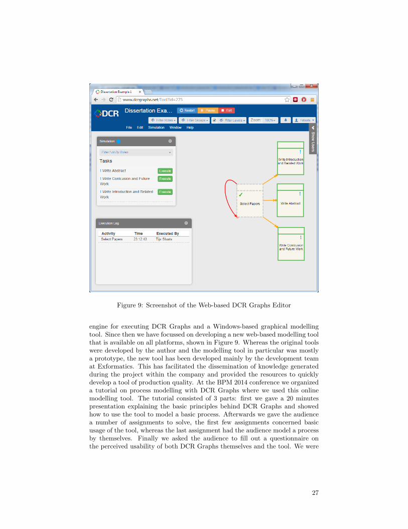
Figure 9: Screenshot of the Web-based DCR Graphs Editor
engine for executing DCR Graphs and a Windows-based graphical modellingtool. Since then we have focussed on developing a new web-based modelling toolthat is available on all platforms, shown in Figure 9. Whereas the original toolswere developed by the author and the modelling tool in particular was mostlya prototype, the new tool has been developed mainly by the development teamat Exformatics. This has facilitated the dissemination of knowledge generatedduring the project within the company and provided the resources to quicklydevelop a tool of production quality. At the BPM 2014 conference we organizeda tutorial on process modelling with DCR Graphs where we used this onlinemodelling tool. The tutorial consisted of 3 parts: first we gave a 20 minutespresentation explaining the basic principles behind DCR Graphs and showedhow to use the tool to model a basic process. Afterwards we gave the audiencea number of assignments to solve, the first few assignments concerned basicusage of the tool, whereas the last assignment had the audience model a processby themselves. Finally we asked the audience to fill out a questionnaire onthe perceived usability of both DCR Graphs themselves and the tool. We were
27

pleasantly surprised by the reactions given in the questionnaire, overall both thetool and DCR Graphs themselves scored significantly above average in regardsto understandability and usability. In all fairness the tutorial was done with anacademic audience, which may not be a fair representation of the actual usersof DCR Graphs. The near future we plan to do a number of similar workshopswith regular business users and publish the results.
During the project the attitude towards DCR Graphs within Exformaticschanged, originally the intention was mainly to use DCR Graphs as a workflowlanguage within their proprietary Electronic Case Management System, butduring the project and especially after the development of the online modellingtool the company is now considering also offering more consultancy-orientedservices, where DCR Graphs are used to model and analyse customers processesand where the tools are offered as a product of their own without needing tobe embedded within the ECM system. We believe that this development showsthat there is a strong confidence within Exformatics that DCR Graphs are auseful tool for modelling and developing flexible processes.
3.2 Future Work
During the project we worked on formally mapping DCR Graphs to other nota-tions such as Petri nets, Declare and the Guard-Stage-Milestone model. Becauseof other angles taking priority none of these initiatives were finalized and pub-lished, but we still believe they hold merit and it would be useful to continuethe work as time allows. In the case of mapping to Petri nets, the work wouldalso tie in nicely with the work on Hybrid Process Technologies, as being ableof formally mapping between DCR Graphs and Petri nets would facilitate usingthem together in a hybrid approach.
The long-term goal of adding liveness constraints to session types is to beable of combining the work on session types and DCR Graphs and thereby beable of specifying the interfaces of declarative processes as behavioural types.Introducing a calculus representation of DCR Graphs is another step in thisdirection, but a true mapping that would allow session types to be used togetherwith DCR Graphs still needs to be researched.
Paper 8.1 made a first step towards empirically testing the perceived under-standability and usability of DCR Graphs by actual practitioners. At BPM 2013we followed up on this initial effort by organising a hands-on tutorial sessionon DCR Graphs, including a questionnaire to be filled out by the participantsaimed at gauging the understandability of the notation. We believe this workhas a lot of merit and it would be good to continue investigating the usabilityof DCR Graphs (and declarative notations in general) in the future, both as away to improve upon the notations by identifying their weak points and buildtrust in their actual applicability.
One area of future work that is of particular interest to the author is thatof hybrid BPM technologies as we believe there are many open research oppor-tunities in this field. In terms of notations it would be interesting to look atcombining declarative notations with BPMN. Because it is the flow-based no-
28

tation most widely adopted by industry a combined approach that supports itwould have the best chance of reaching practitioners, with the additional benefitof making practitioners more aware of declarative approaches.
We also believe that it would be worthwhile to investigate existing notationsand evaluate to what extend they already fall within the hybrid paradigm.Petri nets are a good example of a notation that we believe has both flow-and constraint-based aspects to it: while the tokens moving around in a Petrinet have a strong sense of flow to them, arcs blocking transitions from firinghave a strong resemblance to constraints. Of particular note is that transitionsthat do not have any incoming arcs are allowed to fire at any time and anynumber of times, similar to how unconstrained activities can fire at any time inDCR Graphs and Declare, something that is often considered a main propertyof declarative notations. As we noted in paper 8.2 this property makes Petrinets particularly well-suited to combining with the more traditional declarativenotations.
In terms of hybrid process mining the approach we developed in paper 8.3still has ample room for improvements, in particular it is not very good atdistinguishing parallelism from flexibility and only allows activities to occur ina single sub-process.
We are also interested in other hybrid approaches, for example the possibilityof using flow-based and declarative notations together, but not necessarily in-termixed within a single model, for specifying different properties of a process.For example one could use declarative notations for the initial requirementsspecifications of a system and then derive (guided by user input) one or moreflow-based models that implement the desired processes from these rules, whichcould be used to implement the actual running processes. In this case it wouldbe up to the modeller that derives the flow-based models from the constraint-based specification to decide how much flexibility should be maintained in theactual implementation. By logging the derivation steps taken it would also bepossible to relate the flow-based implementation back to the constraint-basedspecification that gave rise to it.
29
List of Publications
Journal publications
1. Contracts for Cross-organizational Workflows as Timed Dynamic Condi-tion Response Graphs, Thomas Hildebrandt, Raghava Rao Mukkamala,Tijs Slaats and Francesco Zanitti, In Journal of Logic and Algebraic Pro-gramming Special issue on Contract Oriented Software.
Conference publications
1. Hierarchical Declarative Modelling with Refinement and Sub-processes, SorenDebois, Thomas Hildebrandt and Tijs Slaats, 12th International Confer-ence on Business Process Management (BPM 2014).
2. The Automated Discovery of Hybrid Processes, Fabrizio Maria Maggi, TijsSlaats and Hajo A. Reijers, 12th International Conference on BusinessProcess Management (BPM 2014).
3. A Case for Declarative Process Modelling: Agile Development of a GrantApplication System, Sren Debois, Thomas Hildebrandt, Morten Marquardand Tijs Slaats, 3rd International Workshop on Adaptive Case Manage-ment and other non-workflow approaches to BPM (AdaptiveCM 2014).
4. Type Checking Liveness for Collaborative Processes with Bounded andUnbounded Recursion, Soren Debois, Thomas Hildebrandt, Tijs Slaatsand Nobuko Yoshida, Accepted for 34th IFIP International Conferenceon Formal Techniques for Distributed Objects, Components and Systems(FORTE 2014).
5. Dynamic Condition Response Graphs for Trustworthy Adaptive Case Man-agement, Thomas Hildebrandt, Raghava Rao Mukkamala, Tijs Slaats andMorten Marquard, In Proceedings of International Workshop on AdaptiveCase Management and other non-workflow approaches to BPM (Adap-tiveCM 2013).
6. Towards Trustworthy Adaptive Case Management with Dynamic Condi-tion Response Graphs, Raghava Rao Mukkamala, Thomas Hildebrandtand Tijs Slaats, In Proceedings of The Enterprise Computing Conference(EDOC 2013).
7. Exformatics Declarative Case Management Workflows as DCR Graphs,Thomas Hildebrandt, Morten Marquard, Raghava Rao Mukkamala andTijs Slaats, In Proceedings of International Conference on Business Pro-cess Management (BPM 2013).
8. Declarative ModelingAn Academic Dream or the Future for BPM?, HajoA. Reijers, Tijs Slaats and Christian Stahl, In Proceedings of InternationalConference on Business Process Management (BPM 2013).
30
9. Mixing Paradigms for More Comprehensible Models, Michael Westergaardand Tijs Slaats, In Proceedings of International Conference on BusinessProcess Management (BPM 2013).
10. Rsvp: Live sessions with responses, Thomas Hildebrandt, Marco Car-bone, and Tijs Slaats, In Proceedings of 1st International Workshop onBehavioural Types (BEAT13).
11. Modular Context-Sensitive and Aspect-Oriented Processes with DynamicCondition Response Graphs, Thomas Hildebrandt, Raghava Rao Mukka-mala, Tijs Slaats and Francesco Zanitti, In Proceedings of Foundations ofAspect-Oriented Languages workshop (FOAL 2013).
12. Safe Distribution of Declarative Processes, Thomas Hildebrandt, RaghavaRao Mukkamala and Tijs Slaats, In Proceedings of 9th International Con-ference on Software Engineering and Formal Methods (SEFM’11).
13. Designing a Cross-organizational Case Management System using Dy-namic Condition Response Graphs, Thomas Hildebrandt, Raghava RaoMukkamala and Tijs Slaats, In Proceedings of Fifteenth IEEE Interna-tional EDOC Conference (EDOC’11).
14. Declarative Modelling and Safe Distribution of Healthcare Workflows, ThomasHildebrandt, Raghava Rao Mukkamala and Tijs Slaats. In Proceedingsof 1st International Symposium on Foundations of Health InformationEngineering and Systems (FHIES’11).
15. Nested Dynamic Condition Response Graphs, Thomas Hildebrandt, RaghavaRao Mukkamala and Tijs Slaats, In Proceedings of 4th International Con-ference on Fundamentals of Software Engineering (FSEN’11).
31
References
[1] Wil M. P. van der Aalst. Verification of workflow nets. In Proceedings ofthe 18th International Conference on Application and Theory of Petri Nets,ICATPN ’97, pages 407–426, London, UK, UK, 1997. Springer-Verlag.
[2] Rakesh Agrawal, Dimitrios Gunopulos, and Frank Leymann. Mining pro-cess models from workflow logs. In Proceedings of the 6th International Con-ference on Extending Database Technology: Advances in Database Technol-ogy, EDBT ’98, pages 469–483, London, UK, UK, 1998. Springer-Verlag.
[3] Kamal Bhattacharya, Cagdas Gerede, Richard Hull, Rong Liu, and JianwenSu. Towards formal analysis of artifact-centric business process models. InIn preparation, pages 288–304, 2007.
[4] Federico Chesani, E. Lamma, Paola Mello, M. Montali, F. Riguzzi, andS. Storari. Exploiting Inductive Logic Programming Techniques for Declar-ative Process Mining. Transactions on Petri Nets and Other Models ofConcurrency (ToPNoC), Special Issue on Concurrency in Process-AwareInformation Systems, 5460:278–295, 2009.
[5] Thomas H Davenport, Sirkka L Jarvenpaa, and Michael C Beers. Improvingknowledge work processes. Sloan management review, 1996.
[6] Johannes De Smedt, Jochen De Weerdt, and Jan Vanthienen. Multi-paradigm process mining: Retrieving better models by combining rules andsequences. In Robert Meersman, Herv Panetto, Tharam Dillon, MicheleMissikoff, Lin Liu, Oscar Pastor, Alfredo Cuzzocrea, and Timos Sellis, ed-itors, On the Move to Meaningful Internet Systems: OTM 2014 Confer-ences, volume 8841 of Lecture Notes in Computer Science, pages 446–453.Springer Berlin Heidelberg, 2014.
[7] Pierre-Malo Denielou and Nobuko Yoshida. Multiparty session types meetcommunicating automata. In ESOP, pages 194–213, 2012.
[8] Nirmit Desai, Amit K. Chopra, and Munindar P. Singh. Amoeba: Amethodology for modeling and evolving cross-organizational business pro-cesses. ACM Trans. Softw. Eng. Methodol., 19(2):6:1–6:45, October 2009.
[9] C. Di Ciccio and M. Mecella. Mining constraints for artful processes. InBIS, 2012.
[10] Peter F. Drucker. Management Challenges for the 21st Century. Harper-Business, 2001.
[11] Rik Eshuis and Juliane Dehnert. Reactive petri nets for workflow modeling.In Applications and Theory of Petri Nets 2003, pages 296–315. Springer,2003.
32
[12] Rik Eshuis and Roel Wieringa. A formal semantics for uml activitydiagrams-formalising workflow models. 2001.
[13] J. Esparza and M. Nielsen. Decidability Issues for Petri Nets - a Survey.Bulletin of the European Association for Theoretical Computer Science,52:245–262, 1994.
[14] Dirk Fahland, Daniel Lbke, Jan Mendling, Hajo Reijers, Barbara Weber,Matthias Weidlich, and Stefan Zugal. Declarative versus imperative pro-cess modeling languages: The issue of understandability. In Terry Halpin,John Krogstie, Selmin Nurcan, Erik Proper, Rainer Schmidt, Pnina Soffer,and Roland Ukor, editors, Enterprise, Business-Process and InformationSystems Modeling, volume 29 of Lecture Notes in Business InformationProcessing, pages 353–366. Springer Berlin Heidelberg, 2009.
[15] Paul Grefen, Karl Aberer, Heiko Ludwig, and Yigal Hoffner. Crossflow:Cross-organizational workflow management for service outsourcing in dy-namic virtual enterprises. Bulletin of the Technical Committee on DataEngineering, 24(1):52–57, 2001.
[16] Vivian C.T. Hermans. A hybrid process modelingapproach. Master’s thesis,Eindhoven University of Technology, the Netherlands, 2014.
[17] Thomas Hildebrandt and Raghava Rao Mukkamala. Declarative event-based workflow as distributed dynamic condition response graphs. In Post-proceedings of PLACES 2010, 2010.
[18] Kohei Honda, Vasco Vasconcelos, and Makoto Kubo. Language primitivesand type discipline for structured communication-based programming. InESOP, pages 122–138, 1998.
[19] Kohei Honda, Nobuko Yoshida, and Marco Carbone. Multiparty asyn-chronous session types. In POPL, pages 273–284, 2008.
[20] Richard Hull, Elio Damaggio, Riccardo De Masellis, Fabiana Fournier,Manmohan Gupta, Fenno Terry Heath, III, Stacy Hobson, Mark Linehan,Sridhar Maradugu, Anil Nigam, Piwadee Noi Sukaviriya, and Roman Va-culin. Business artifacts with guard-stage-milestone lifecycles: managingartifact interactions with conditions and events. In Proc. of DEBS ’11,pages 51–62, New York, NY, USA, 2011. ACM.
[21] Richard Hull, Elio Damaggio, Fabiana Fournier, Manmohan Gupta,Fenno Terry Heath, III, Stacy Hobson, Mark Linehan, Sridhar Maradugu,Anil Nigam, Piyawadee Sukaviriya, and Roman Vaculin. Introducing theguard-stage-milestone approach for specifying business entity lifecycles. InProc. of WS-FM’10, pages 1–24, Berlin, Heidelberg, 2011. Springer-Verlag.
[22] K. Jensen and L.M. Kristensen. Coloured Petri Nets – Modelling and Val-idation of Concurrent Systems. Springer, 2009.
33
[23] Kurt Jensen. Coloured petri nets. Springer, 1987.
[24] Ekkart Kindler, Wolfgang Reisig, Hagen Vlzer, and Rolf Walter. Petri netbased verification of distributed algorithms: An example. Formal Aspectsof Computing, 9, 1996.
[25] Marjanca Koetsier, Paul Grefen, and Jochem Vonk. Contracts for cross-organizational workflow management. In Kurt Bauknecht, SanjayKumarMadria, and Gnther Pernul, editors, Electronic Commerce and Web Tech-nologies, volume 1875 of Lecture Notes in Computer Science, pages 110–121. Springer Berlin Heidelberg, 2000.
[26] E. Lamma, P. Mello, F. Riguzzi, and S. Storari. Applying inductive logicprogramming to process mining. In Inductive Logic Programming, volume4894. 2008.
[27] Sander J. J. Leemans, Dirk Fahland, and Wil M. P. van der Aalst. Dis-covering block-structured process models from event logs - a constructiveapproach. In Jos Manuel Colom and Jrg Desel, editors, Petri Nets, volume7927 of Lecture Notes in Computer Science, pages 311–329. Springer, 2013.
[28] F.M. Maggi, R.P.J.C. Bose, and W.M.P. van der Aalst. Efficient discoveryof understandable declarative models from event Logs. In CAiSE, pages270–285, 2012.
[29] F.M. Maggi, A.J. Mooij, and W.M.P. van der Aalst. User-Guided Discoveryof Declarative Process Models. In 2011 IEEE Symposium on ComputationalIntelligence and Data Mining. IEEE, 2011.
[30] F.M. Maggi, A.J. Mooij, and W.M.P. van der Aalst. User-guided discoveryof declarative process models. In CIDM, pages 192–199, 2011.
[31] Fabrizio Maria Maggi, Marco Montali, Michael Westergaard, and Wil M. P.van der Aalst. Monitoring business constraints with linear temporal logic:An approach based on colored automata. In Business Process Management(BPM) 2011, volume 6896 of Lecture Notes in Computer Science, pages 32–147, 2011.
[32] Marco Montali. Specification and Verification of Declarative Open Inter-action Models: a Logic-Based Approach, volume 56 of Lecture Notes inBusiness Information Processing. Springer, 2010.
[33] Marco Montali, Maja Pesic, Wil MP van der Aalst, Federico Chesani, PaolaMello, and Sergio Storari. Declarative specification and verification of ser-vice choreographiess. ACM Transactions on the Web (TWEB), 4(1):3,2010.
[34] Raghava Rao Mukkamala. A Formal Model For Declarative Workflows -Dynamic Condition Response Graphs. PhD thesis, IT University of Copen-hagen, March 2012.
34

[35] R.R. Mukkamala and T.T. Hildebrandt. From dynamic condition responsestructures to buchi automata. In Theoretical Aspects of Software Engineer-ing (TASE), 2010 4th IEEE International Symposium on, pages 187 –190,aug. 2010.
[36] N. A. Mulyar, M. H. Schonenberg, Mans, and van der Aalst. Towards aTaxonomy of Process Flexibility (Extended Version). 2007.
[37] Mogens Nielsen, Gordon Plotkin, and Glynn Winskel. Petri nets, eventstructures and domains. In Gilles Kahn, editor, Semantics of ConcurrentComputation, volume 70 of Lecture Notes in Computer Science, pages 266–284. Springer Berlin / Heidelberg, 1979. 10.1007/BFb0022474.
[38] Object Management Group. Case Management Model and Notation, ver-sion 1.0. Webpage, may 2014. http://www.omg.org/spec/CMMN/1.0/PDF.
[39] Object Management Group BPMN Technical Committee. Business ProcessModel and Notation, version 2.0. Webpage, january 2011. http://www.
omg.org/spec/BPMN/2.0/PDF.
[40] M. Pesic, H. Schonenberg, and W.M.P. van der Aalst. DECLARE: FullSupport for Loosely-Structured Processes. In Proceedings of the 11th IEEEInternational Enterprise Distributed Object Computing Conference, pages287–. IEEE Computer Society, Washington, DC, USA, 2007.
[41] Carl Adam Petri. Kommunikation mit Automaten. PhD thesis, UniversittHamburg, 1962.
[42] Johannes Prescher, Claudio Di Ciccio, and Jan Mendling. From declar-ative processes to imperative models. In Proceedings of the 4th Interna-tional Symposium on Data-driven Process Discovery and Analysis (SIM-PDA 2014), Milan, Italy, November 19-21, 2014., pages 162–173, 2014.
[43] Anne Vinter Ratzer, Lisa Wells, Henry Michael Lassen, Mads Laursen, Ja-cob Frank Qvortrup, Martin Stig Stissing, Michael Westergaard, SørenChristensen, and Kurt Jensen. Cpn tools for editing, simulating, andanalysing coloured petri nets. In Applications and Theory of Petri Nets2003, pages 450–462. Springer, 2003.
[44] Manfred Reichert and Barbara Weber. Enabling Flexibility in Process-Aware Information Systems: Challenges, Methods, Technologies. Springer,Berlin-Heidelberg, 2012.
[45] Shazia Sadiq, Wasim Sadiq, and Maria Orlowska. Pockets of flexibilityin workflow specification. In Hideko S.Kunii, Sushil Jajodia, and ArneSlvberg, editors, Conceptual Modeling ER 2001, volume 2224 of LectureNotes in Computer Science, pages 513–526. Springer Berlin Heidelberg,2001.
35

[46] Keith D. Swenson. Mastering the Unpredictable: How Adaptive Case Man-agement Will Revolutionize the Way That Knowledge Workers Get ThingsDone. Meghan-Kiffer Press, 2010.
[47] W. M. P. van der Aalst, M. Pesic, and H. Schonenberg. Declarative work-flows: Balancing between flexibility and support. Computer Science - R&D,23(2):99–113, 2009.
[48] W. M. P. van der Aalst, B. F. van Dongen, J. Herbst, L. Maruster,G. Schimm, and A. J. M. M. Weijters. Workflow mining: A survey ofissues and approaches. Data Knowl. Eng., 47(2):237–267, November 2003.
[49] Wil van der Aalst, Arya Adriansyah, Ana Karla Alves de Medeiros, FrancoArcieri, Thomas Baier, Tobias Blickle, Jagadeesh Chandra Bose, Petervan den Brand, Ronald Brandtjen, Joos Buijs, Andrea Burattin, JosepCarmona, Malu Castellanos, Jan Claes, Jonathan Cook, Nicola Costantini,Francisco Curbera, Ernesto Damiani, Massimiliano de Leoni, Pavlos Delias,Boudewijn van Dongen, Marlon Dumas, Schahram Dustdar, Dirk Fahland,Diogo R. Ferreira, Walid Gaaloul, Frank van Geffen, Sukriti Goel, Chris-tian Gunther, Antonella Guzzo, Paul Harmon, Arthur ter Hofstede, JohnHoogland, Jon Espen Ingvaldsen, Koki Kato, Rudolf Kuhn, Akhil Kumar,Marcello La Rosa, Fabrizio Maggi, Donato Malerba, Ronny Mans, AlbertoManuel, Martin McCreesh, Paola Mello, Jan Mendling, Marco Montali,Hamid Motahari Nezhad, Michael zur Muehlen, Jorge Munoz-Gama, LuigiPontieri, Joel Ribeiro, Anne Rozinat, Hugo Seguel Perez, Ricardo SeguelPerez, Marcos Sepulveda, Jim Sinur, Pnina Soffer, Minseok Song, Alessan-dro Sperduti, Giovanni Stilo, Casper Stoel, Keith Swenson, Maurizio Ta-lamo, Wei Tan, Chris Turner, Jan Vanthienen, George Varvaressos, EricVerbeek, Marc Verdonk, Roberto Vigo, Jianmin Wang, Barbara Weber,Matthias Weidlich, Ton Weijters, Lijie Wen, Michael Westergaard, andMoe Wynn. Process mining manifesto. In F Daniel, K Barkaoui, andS Dustdar, editors, Lecture Notes in Business Information Processing, vol-ume 99, pages 169–194. Springer, 2012.
[50] Wil van der Aalst, Maja Pesic, Helen Schonenberg, Michael Westergaard,and Fabrizio M. Maggi. Declare. Webpage, 2010. http://www.win.tue.
nl/declare/.
[51] Wil van der Aalst, Ton Weijters, and Laura Maruster. Workflow mining:Discovering process models from event logs. IEEE Trans. on Knowl. andData Eng., 16(9):1128–1142, September 2004.
[52] Wil M. P. van der Aalst. The application of petri nets to workflow man-agement. Journal of Circuits, Systems, and Computers, 8(1):21–66, 1998.
[53] Wil M. P. van der Aalst. Process Mining: Discovery, Conformance andEnhancement of Business Processes. Springer Publishing Company, Incor-porated, 1st edition, 2011.
36
[54] Wil M. P. Van Der Aalst, Arthur H. M. Ter Hofstede, and Mathias Weske.Business process management: A survey. In Proceedings of the 2003 In-ternational Conference on Business Process Management, BPM’03, pages1–12, Berlin, Heidelberg, 2003. Springer-Verlag.
[55] Wil M.P van der Aalst and Maja Pesic. DecSerFlow: Towards a trulydeclarative service flow language. In M. Bravetti, M. Nunez, and GianluigiZavattaro, editors, Proceedings of Web Services and Formal Methods (WS-FM 2006), volume 4184 of LNCS, pages 1–23. Springer Verlag, 2006.
[56] W.M.P. van der Aalst, M. Adams, A.H.M. ter Hofstede, M. Pesic, andH. Schonenberg. Flexibility as a service. In Lei Chen, Chengfei Liu, QingLiu, and Ke Deng, editors, Database Systems for Advanced Applications,volume 5667 of Lecture Notes in Computer Science, pages 319–333. SpringerBerlin Heidelberg, 2009.
[57] Wil van van der Aalst and Christian Stahl. Modeling Business Processes:A Petri Net-Oriented Approach. The MIT Press, 2011.
[58] W Vanderaalst, M Weske, and D Grunbauer. Case handling: a newparadigm for business process support. Data & Knowledge Engineering,53(2):129–162, 2005.
[59] Daniele Varacca, Hagen Vlzer, and Glynn Winskel. Probabilistic eventstructures and domains. Theoretical Computer Science, 358(23):173 – 199,2006. Concurrency Theory (CONCUR 2004) 15th International Conferenceon Concurrency Theory 2004.
[60] Vasco Vasconcelos. Fundamentals of session types. I&C, 217:52–70, 2012.
[61] Hagen Vlzer. An overview of bpmn 2.0 and its potential use. In JanMendling, Matthias Weidlich, and Mathias Weske, editors, Business Pro-cess Modeling Notation, volume 67 of Lecture Notes in Business Informa-tion Processing, pages 14–15. Springer Berlin Heidelberg, 2010.
[62] Barbara Weber, Manfred Reichert, and Stefanie Rinderle-Ma. Change pat-terns and change support features - enhancing flexibility in process-awareinformation systems. Data and Knowledge Engineering, 66(3):438–466,September 2008.
[63] Hans Weigand and Willem-Jan van den Heuvel. Cross-organizational work-flow integration using contracts. Decis. Support Syst., 33(3):247–265, July2002.
[64] Mathias Weske. Business Process Management: Concepts, Languages, Ar-chitectures. Springer-Verlag New York, Inc., Secaucus, NJ, USA, 2007.
[65] Glynn Winskel. Events in Computation. PhD thesis, Edinburgh University,1980.
37
[66] Glynn Winskel. Event structures. In Wilfried Brauer, Wolfgang Reisig,and Grzegorz (Eds.) Rozenberg, editors, Advances in Petri Nets, volumeVol. 255 of Lecture Notes in Computer Science,, pages 325–392. Springer,1986.
[67] Glynn Winskel. Events, causality and symmetry. The Computer Journal,54(1):42–57, 2011.
[68] Nobuko Yoshida and Vasco Thudichum Vasconcelos. Language primitivesand type discipline for structured communication-based programming re-visited: Two systems for higher-order session communication. ENTCS,171(4):73–93, 2007.
[69] Stefan Zugal, Pnina Soffer, Cornelia Haisjackl, Jakob Pinggera, ManfredReichert, and Barbara Weber. Investigating expressiveness and understand-ability of hierarchy in declarative business process models. Software &Systems Modeling, June 2014.
[70] Stefan Zugal, Pnina Soffer, Jakob Pinggera, and Barbara Weber. Expres-siveness and understandability considerations of hierarchy in declarativebusiness process models. In BMMDS/EMMSAD, volume 113 of LectureNotes in Business Information Processing, pages 167–181. Springer, 2012.
38

4 Hierarchical Dynamic Condition Response Graphs
39
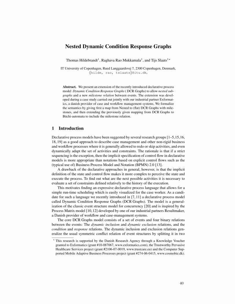
Nested Dynamic Condition Response Graphs
Thomas Hildebrandt1, Raghava Rao Mukkamala1, and Tijs Slaats1?
IT University of Copenhagen, Rued Langgaardsvej 7, 2300 Copenhagen, Denmark,{hilde, rao, tslaats}@itu.dk,
Abstract. We present an extension of the recently introduced declarative processmodel Dynamic Condition Response Graphs ( DCR Graphs) to allow nested sub-graphs and a new milestone relation between events. The extension was devel-oped during a case study carried out jointly with our industrial partner Exformat-ics, a danish provider of case and workflow management systems. We formalizethe semantics by giving first a map from Nested to (flat) DCR Graphs with mile-stones, and then extending the previously given mapping from DCR Graphs toBuchi-automata to include the milestone relation.
1 Introduction
Declarative process models have been suggested by several research groups [1–5,15,16,18, 19] as a good approach to describe case management and other non-rigid businessand workflow processes where it is generally allowed to redo or skip activities, and evendynamically adapt the set of activities and constraints. The rationale is that if a strictsequencing is the exception, then the implicit specification of control flow in declarativemodels is more appropriate than notations based on explicit control flows such as the(typical use of) Business Process Model and Notation (BPMN) 2.0 [13].
A drawback of the declarative approaches in general, however, is that the implicitdefinition of the state and control flow makes it more complex to perceive the state andexecute the process. To find out what are the next possible activities it is necessary toevaluate a set of constraints defined relatively to the history of the execution.
This motivates finding an expressive declarative process language that allows for asimple run-time scheduling which is easily visualized for the case worker. As a candi-date for such a language we recently introduced in [7, 11] a declarative process modelcalled Dynamic Condition Response Graphs (DCR Graphs). The model is a general-ization of the classic event structure model for concurrency [20] and is inspired by theProcess Matrix model [10,12] developed by one of our industrial partners Resultmaker,a Danish provider of workflow and case-management systems.
The core DCR Graphs model consists of a set of events and four binary relationsbetween the events: The dynamic inclusion and dynamic exclusion relations, and thecondition and response relations. The dynamic inclusion and exclusion relations gen-eralize the usual symmetric conflict relation of event structures by splitting it in two? This research is supported by the Danish Research Agency through a Knowledge Voucher
granted to Exformatics (grant #10-087067, www.exformatics.com), the Trustworthy PervasiveHealthcare Services project (grant #2106-07-0019, www.trustcare.eu) and the Computer Sup-ported Mobile Adaptive Business Processes project (grant #274-06-0415, www.cosmobiz.dk).
40
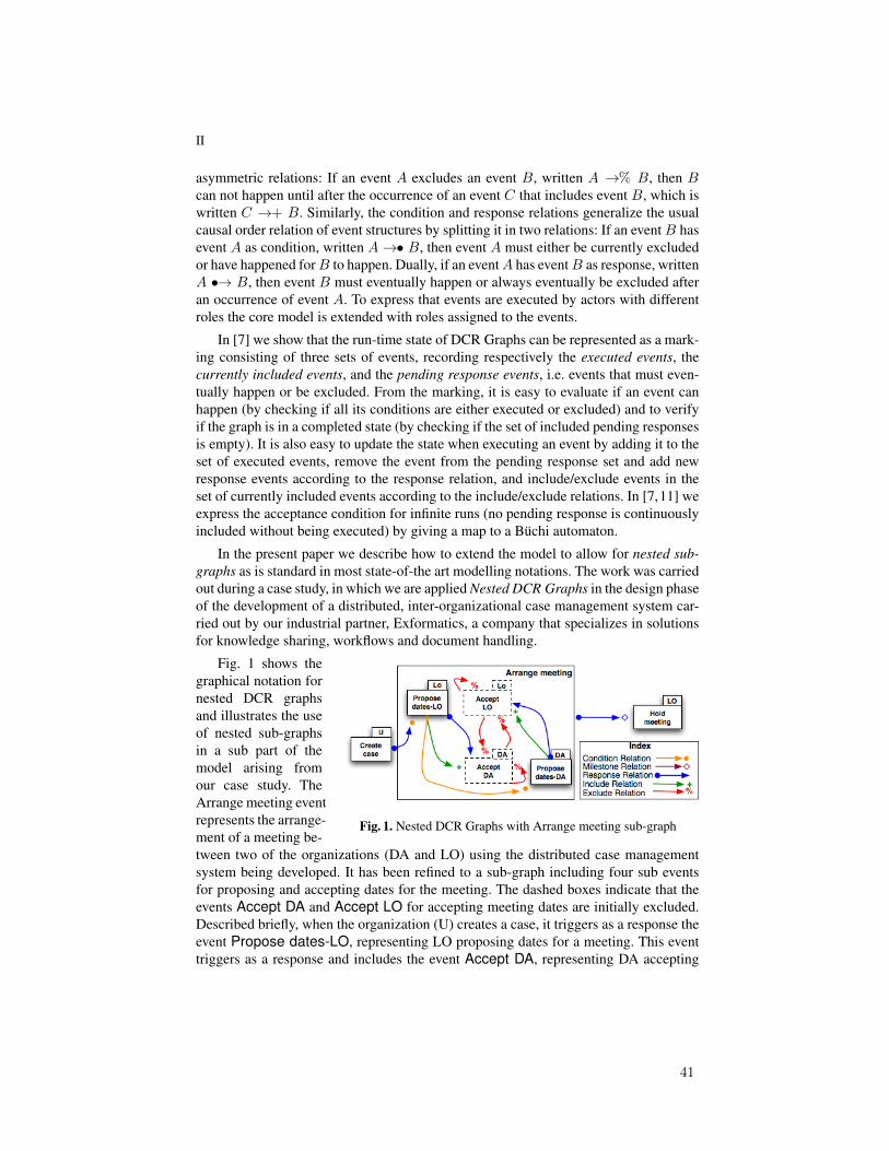
II
asymmetric relations: If an event A excludes an event B, written A →% B, then Bcan not happen until after the occurrence of an event C that includes event B, which iswritten C →+ B. Similarly, the condition and response relations generalize the usualcausal order relation of event structures by splitting it in two relations: If an eventB hasevent A as condition, written A→• B, then event A must either be currently excludedor have happened forB to happen. Dually, if an eventA has eventB as response, writtenA •→ B, then event B must eventually happen or always eventually be excluded afteran occurrence of event A. To express that events are executed by actors with differentroles the core model is extended with roles assigned to the events.
In [7] we show that the run-time state of DCR Graphs can be represented as a mark-ing consisting of three sets of events, recording respectively the executed events, thecurrently included events, and the pending response events, i.e. events that must even-tually happen or be excluded. From the marking, it is easy to evaluate if an event canhappen (by checking if all its conditions are either executed or excluded) and to verifyif the graph is in a completed state (by checking if the set of included pending responsesis empty). It is also easy to update the state when executing an event by adding it to theset of executed events, remove the event from the pending response set and add newresponse events according to the response relation, and include/exclude events in theset of currently included events according to the include/exclude relations. In [7,11] weexpress the acceptance condition for infinite runs (no pending response is continuouslyincluded without being executed) by giving a map to a Buchi automaton.
In the present paper we describe how to extend the model to allow for nested sub-graphs as is standard in most state-of-the art modelling notations. The work was carriedout during a case study, in which we are applied Nested DCR Graphs in the design phaseof the development of a distributed, inter-organizational case management system car-ried out by our industrial partner, Exformatics, a company that specializes in solutionsfor knowledge sharing, workflows and document handling.
Fig. 1. Nested DCR Graphs with Arrange meeting sub-graph
Fig. 1 shows thegraphical notation fornested DCR graphsand illustrates the useof nested sub-graphsin a sub part of themodel arising fromour case study. TheArrange meeting eventrepresents the arrange-ment of a meeting be-tween two of the organizations (DA and LO) using the distributed case managementsystem being developed. It has been refined to a sub-graph including four sub eventsfor proposing and accepting dates for the meeting. The dashed boxes indicate that theevents Accept DA and Accept LO for accepting meeting dates are initially excluded.Described briefly, when the organization (U) creates a case, it triggers as a response theevent Propose dates-LO, representing LO proposing dates for a meeting. This eventtriggers as a response and includes the event Accept DA, representing DA accepting
41
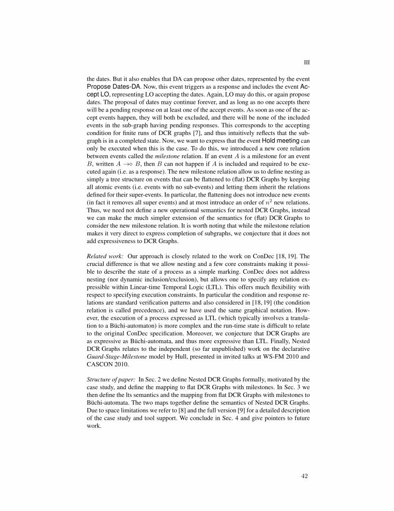
III
the dates. But it also enables that DA can propose other dates, represented by the eventPropose Dates-DA. Now, this event triggers as a response and includes the event Ac-cept LO, representing LO accepting the dates. Again, LO may do this, or again proposedates. The proposal of dates may continue forever, and as long as no one accepts therewill be a pending response on at least one of the accept events. As soon as one of the ac-cept events happen, they will both be excluded, and there will be none of the includedevents in the sub-graph having pending responses. This corresponds to the acceptingcondition for finite runs of DCR graphs [7], and thus intuitively reflects that the sub-graph is in a completed state. Now, we want to express that the event Hold meeting canonly be executed when this is the case. To do this, we introduced a new core relationbetween events called the milestone relation. If an event A is a milestone for an eventB, written A →� B, then B can not happen if A is included and required to be exe-cuted again (i.e. as a response). The new milestone relation allow us to define nesting assimply a tree structure on events that can be flattened to (flat) DCR Graphs by keepingall atomic events (i.e. events with no sub-events) and letting them inherit the relationsdefined for their super-events. In particular, the flattening does not introduce new events(in fact it removes all super events) and at most introduce an order of n2 new relations.Thus, we need not define a new operational semantics for nested DCR Graphs, insteadwe can make the much simpler extension of the semantics for (flat) DCR Graphs toconsider the new milestone relation. It is worth noting that while the milestone relationmakes it very direct to express completion of subgraphs, we conjecture that it does notadd expressiveness to DCR Graphs.
Related work: Our approach is closely related to the work on ConDec [18, 19]. Thecrucial difference is that we allow nesting and a few core constraints making it possi-ble to describe the state of a process as a simple marking. ConDec does not addressnesting (nor dynamic inclusion/exclusion), but allows one to specify any relation ex-pressible within Linear-time Temporal Logic (LTL). This offers much flexibility withrespect to specifying execution constraints. In particular the condition and response re-lations are standard verification patterns and also considered in [18, 19] (the conditionrelation is called precedence), and we have used the same graphical notation. How-ever, the execution of a process expressed as LTL (which typically involves a transla-tion to a Buchi-automaton) is more complex and the run-time state is difficult to relateto the original ConDec specification. Moreover, we conjecture that DCR Graphs areas expressive as Buchi-automata, and thus more expressive than LTL. Finally, NestedDCR Graphs relates to the independent (so far unpublished) work on the declarativeGuard-Stage-Milestone model by Hull, presented in invited talks at WS-FM 2010 andCASCON 2010.
Structure of paper: In Sec. 2 we define Nested DCR Graphs formally, motivated by thecase study, and define the mapping to flat DCR Graphs with milestones. In Sec. 3 wethen define the lts semantics and the mapping from flat DCR Graphs with milestones toBuchi-automata. The two maps together define the semantics of Nested DCR Graphs.Due to space limitations we refer to [8] and the full version [9] for a detailed descriptionof the case study and tool support. We conclude in Sec. 4 and give pointers to futurework.
42

IV
2 Nested DCR Graphs and Milestones
We now give the formal definition of the Nested DCR Graph model described infor-mally above, which extends the model in our previous work [7] with nesting and thenew milestone relation→� between events.
Definition 1. A Nested Distributed dynamic condition response graph with milestonesis a tuple (E,B,M,→•, •→,→�,±,Act, l,R,P, as), where
(i) E is the set of events(ii) B : E ⇀ E is a partial function mapping an event to its super-event (if defined),
and we also write eBe′ if e′ = Bk(e) for 0 < k, referred to as the nesting relation(iii) M = (E,R, I) ⊆ atoms(E) × atoms(E) × atoms(E) is the marking, contain-
ing sets of currently executed events (E), currently pending responses (R), andcurrently included events (I).
(iv) →•⊆ E× E is the condition relation(v) •→⊆ E× E is the response relation
(vi) →�⊆ E× E is the milestone relation(vii) ± : E × E ⇀ {+,%} is a partial function defining the dynamic inclusion and
exclusion relations by e→+ e′ if ±(e, e′) = + and e→% e′ if ±(e, e′) = %(viii) Act is the set of actions
(ix) l : E→ Act is a labeling function mapping events to actions.(x) R is a set of roles,
(xi) P is a set of principals (e.g. persons or processors) and(xii) as ⊆ (P ∪ Act)× R is the role assignment relation to principals and actions.
where atoms(E) = {e | ∀e′ ∈ E.B (e′) 6= e} is the set of atomic events.We require that the nesting relation B ⊂ E × E is acyclic and that there are no
infinite sequence of events e1 B e2 B . . .. We will write e D e′ if e B e′ or e = e′, andeEe′ if e′Be or e = e′. We require that the nesting relation is consistent with respect todynamic inclusion/exclusion in the following sense: If eBe′ or e′Be then±(e, e′′) = +implies ±(e′, e′′) 6= % and ±(e, e′′) = % implies ±(e′, e′′) 6= +.
The new elements are the nesting relation B ⊂ E × E and the milestone rela-tion→�⊆ E× E. The consistency between the nesting relation and the dynamic inclu-sion/exclusion is to ensure that when we map a nested DCR Graph to the correspondingflat DCR Graph as defined in Def. 2 below, no atomic event both includes and excludesanother event. That is, if an event e includes (excludes) another event e′′, then any of itssuper or sub events e′ can not exclude (include) the event e′′.
The new elements conservatively extend the DCR Graphs defined in [7] in the sensethat given a Nested dynamic condition response graph as defined in Def. 1, the tu-ple (atoms(E),M,→•, •→,±,Act, l,R,P, as) is a (Distributed) dynamic condition re-sponse graph as defined in [7]. In particular, the semantics will be identical if both theB map and the milestone relation are empty.
A nested distributed dynamic condition response graph can be mapped to a flatdistributed dynamic condition response graph with at most the same number of events.Essentially, all relations are extended to sub events, and then only the atomic events
43

V
are preserved. The labelling function is extended by labelling an atomic event e bythe sequence of labels labelling the chain of super events starting by the event itself:eB e1 . . . ek 6 B. The role assignment is extended to sequences of actions by taking theunion of roles assigned to the actions.
Definition 2. For a Nested DCR GraphG = (E,B,M,→•, •→,→�,±,Act, l,R,P, as)define the underlying flat DCR Graph as
G[ = (atoms(E),M,→•[, •→[,→�[,±[,Act+, l[,R,P, as[),
where rel[ = DrelE for some relation rel ∈ {→•, •→,→�} and±(e, e′)[ = ±(es, e′s)if ±(es, e′s) is defined and eD es and e′ E e′s and l[(e0) = a0.a1.a2 . . . ak if e0 B e1 Be2 . . .B ek and l(ei) = aifor 0 ≤ i ≤ k and as[(a0.a1.a2 . . . ak) = {as(ai) | 0 ≤ i ≤k} and as[(p) = p for p ∈ P.
It is easy to see that the size of the relations may increased by an order of at mostn2 where n is the number of atomic events.
3 Semantics
Below we define the semantics of DCR Graphs with milestones by giving a labelledtransition semantics and a mapping to Buchi-automata.Notation: For a set A we write P(A) for the power set of A. For a binary relation→⊆ A×A and a subset ξ ⊆ A ofA we write→ ξ and ξ → for the set {a ∈ A | (∃a′ ∈ξ | a→ a′)} and the set {a ∈ A | (∃a′ ∈ ξ | a′ → a)} respectively.
Definition 3. For a dynamic condition response graph with milestonesG = (E,M,→•, •→,→�,±, l,Act,R,P, as), we define the corresponding labelled transition systemsT (G) to be the tuple (S,M,→⊆ S ×Act×S) where S = P(E)×P(E)×P(E) is theset of markings of G and M = (R, I,E) ∈ S is the initial marking,→⊆ S × E× (P×Act× R)× S is the transition relation given by M′ (e,(p,a,r))−−−−−−→ M′′ where
(i) M′ = (E′, R′, I ′) is the marking before transition(ii) M′′ = (E′ ∪ {e}, R′′, I ′′) is the marking after transition
(iii) e ∈ I , l(e) = a, p as r, and a as r,(iv) →•e ∩I ′ ⊆ E′,(v) →�e ∩I ′ ∩R′ = ∅,
(vi) I ′′ = (I ′ ∪ e→+) \ e→%,(vii) R′′ = (R′ \ {e}) ∪ e•→,
(viii) E′′ = E′ ∪ {e}
We define a run (e0, (p0, a0, r0)), (e1, (p1, a1, r1)), . . . of the transition system to be a
sequence of labels of a sequence of transitions Mi(ei,(pi,ai,ri))−−−−−−−−−→ Mi+1 starting from
the initial marking. We define a run to be accepting if ∀i ≥ 0, e ∈ Ri.∃j ≥ i.(e =ej ∨ e 6∈ Ij). In words, a run is accepting if no response event is included and pendingforever, i.e. it must either happen at some later state or become excluded.
44
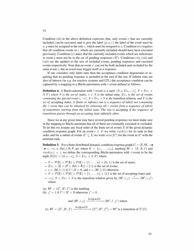
VI
Condition (iii) in the above definition expresses that, only events e that are currentlyincluded, can be executed, and to give the label (p, a, r) the label of the event must bea, p must be assigned to the role r, which must be assigned to a. Condition (iv) requiresthat all condition events to e which are currently included should have been executedpreviously. Condition (v) states that the currently included events which are milestonesto event e must not be in the set of pending responses (R′). Conditions (vi), (vii) and(viii) are the updates to the sets of included events, pending responses and executedevents respectively. Note that an event e′ can not be both included and excluded by thesame event e, but an event may trigger itself as a response.
If one considers only finite runs then the acceptance condition degenerates to re-quiring that no pending response is included at the end of the run. If infinite runs arealso of interest (as e.g. for reactive systems and LTL) the acceptance condition can becaptured by a mapping to a Buchi-automaton with τ -event defined as follows.
Definition 4. A Buchi-automaton with τ -event is a tuple (S, s, Evτ ,→⊆ S × Evτ ×S, F ) where S is the set of states, s ∈ S is the initial state, Evτ is the set of eventscontaining the special event τ ,→⊆ S×Evτ ×S is the transition relation, and F is theset of accepting states. A (finite or infinite) run is a sequence of labels not containingthe τ event that can be obtained by removing all τ events from a sequence of labelsof transitions starting from the initial state. The run is accepting if the sequence oftransitions passes through an accepting state infinitely often.
Since we at any given time may have several pending responses we must make surein the mapping to Buchi-automata that all of them are eventually executed or excluded.To do this we assume any fixed order of the finite set of events E of the given dynamiccondition response graph. For an event e ∈ E we write rank(e) for its rank in thatorder and for a subset of events E′ ⊆ E we write min(E′) for the event in E′ with theminimal rank.
Definition 5. For a finite distributed dynamic condition response graphG = (E,M,→•, •→,→�,±,Act, l,R,P, as) where E = {e1, . . . , en}, marking M = (E,R, I) andrank(ei) = i, we define the corresponding Buchi-automaton with τ -event to be thetuple B(G) = (S, s,→⊆ S × Evτ × S, F ) where
– S = P(E)× P(E)× P(E)× {1, . . . , n} × {0, 1} is the set of states,– Evτ = (E× (P× Act× R)) ∪ {τ} is the set of events,– s = (M, 1, 1) if I ∩R = ∅, and s = (M, 1, 0) otherwise– F = P(E)× P(E)× P(E)× {1, . . . , n} × {1} is the set of accepting states and– →⊆ S × Evτ × S is the transition relation given by (M′, i, j)
τ−−−→ (M′, i, j′)where
(a) M′ = (E′, R′, I ′) is the marking(b) j′ = 1 if I ′ ∩R′ = ∅ otherwise j′ = 0.
and (M′, i, j)(e,(p,a,r))−−−−−−−−−→ (M′′, i′, j′) where
(i) M′ = (E′, R′, I ′)(e,(p,a,r))−−−−−−−−−→ (E′′, R′′, I ′′) = M′′ is a transition of T (D).
45

VII
(ii) For M = {e ∈ I ′ ∩R′ | rank(e) 〉 i} let j′ = 1 if(a) I ′′ ∩R′′ = ∅ or(b) min(M) ∈ (I ′ ∩R′\(I ′′ ∩R′′)) ∪ {e} or(c) M = ∅ and min(I ′ ∩R′) ∈ (I ′ ∩R′\(I ′′ ∩R′′)) ∪ {e}otherwise j′ = 0.
(iii) i′ = rank(min(M)) if min(M) ∈ (I ′ ∩R′\(I ′′ ∩R′′)) ∪ {e} or else(iv) i′ = rank(min(I ′∩R′)) ifM = ∅ andmin(I ′∩R′) ∈ (I ′∩R′\(I ′′∩R′′))∪{e}
or else(v) i′ = i otherwise.
We prove that the mapping from the labelled transition semantics to Buchi-automata issound and complete in the full version of the paper [9].
The formal semantics of DCR graphs mapped to Buchi-automata enabled us to per-form model checking and formal verification of processes specified in DCR graphs. Theprototype implementation allows us to perform verification of both safety and livenessproperties using the SPIN [17] model checker and only verification of safety propertiesusing the ZING [14] model checker. The prototype has also been extended to supportruntime verification, for monitoring of properties specified using Property Patterns [6].
4 Conclusion and Future Work
We have given a conservative extension of the declarative process model DistributedDCR Graphs [7] to allow for nested sub-graphs motivated and guided by a case studycarried out jointly with our industrial partner. A detailed description of the case studyand tool support for DCR Graphs can be found in [8]. The main technical challengewas to formalize the execution and in particular completion of sub-graphs. We do thisby introducing a new milestone relation A→� B, which blocks the event B as long asthere are events inA required to be executed (i.e. required responses). We believe this isthe right notion of completeness of nested sub-graphs. First of all, it coincides with thedefinition of acceptance of finite runs in DCR Graphs [7] recalled in Sec. 3 above. Sec-ondly, its formalization is a simple extension of the labelled transition semantics givenin [7, 11] since it is a condition on the set of pending responses already included in thestates. Finally, it allows for a nested sub-graph to alternate between being completedand not completed, as is often the case in ad hoc case management. This is not possiblein the related ad-hoc sub-process activity in BPMN 2.0. Future work within the Trust-Care and CosmoBiz projects, which are the context of the work, includes exploring theexpressiveness of DCR Graphs, extending the theory and tools for analysis, verificationand model-driven engineering, extending the model to be able to express other relevantfeatures such as multi-instance sub-graphs, time, exceptions, data, types and run-timeadaption, i.e. dynamic changes of the model.
References
1. Kamal Bhattacharya, Cagdas Gerede, Richard Hull, Rong Liu, and Jianwen Su. Towardsformal analysis of artifact-centric business process models. In LNCS, volume 4714, pages288–304, 2007.
46
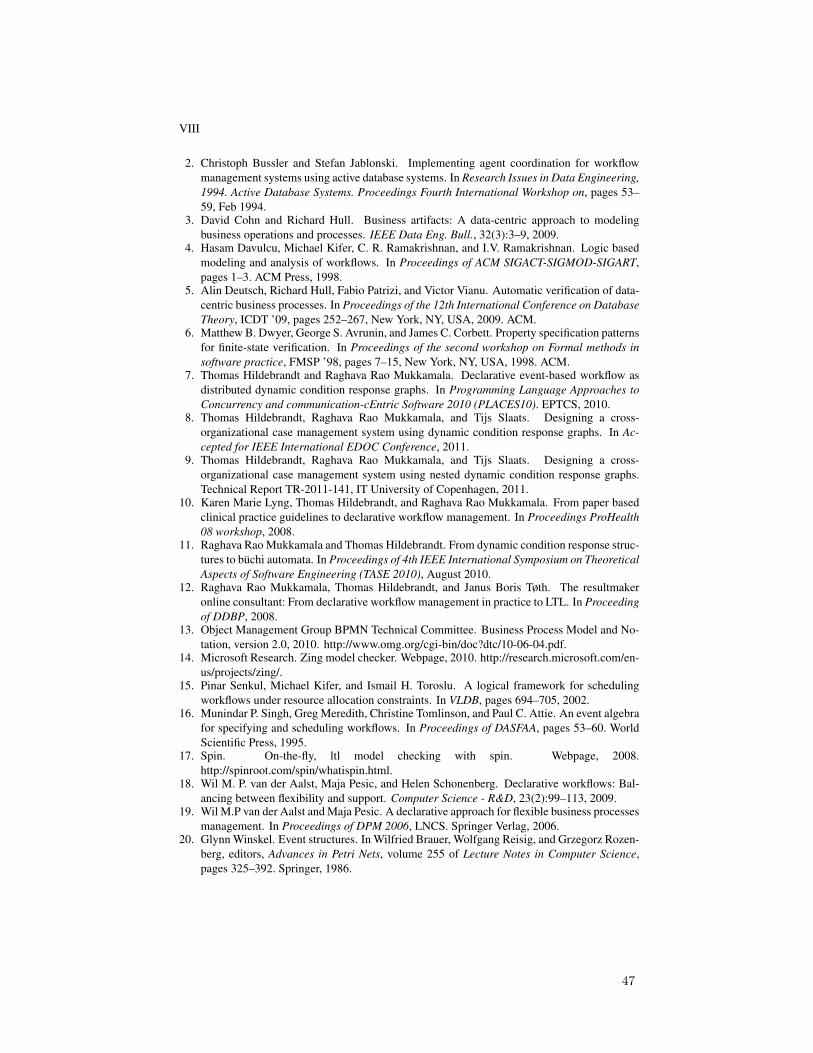
VIII
2. Christoph Bussler and Stefan Jablonski. Implementing agent coordination for workflowmanagement systems using active database systems. In Research Issues in Data Engineering,1994. Active Database Systems. Proceedings Fourth International Workshop on, pages 53–59, Feb 1994.
3. David Cohn and Richard Hull. Business artifacts: A data-centric approach to modelingbusiness operations and processes. IEEE Data Eng. Bull., 32(3):3–9, 2009.
4. Hasam Davulcu, Michael Kifer, C. R. Ramakrishnan, and I.V. Ramakrishnan. Logic basedmodeling and analysis of workflows. In Proceedings of ACM SIGACT-SIGMOD-SIGART,pages 1–3. ACM Press, 1998.
5. Alin Deutsch, Richard Hull, Fabio Patrizi, and Victor Vianu. Automatic verification of data-centric business processes. In Proceedings of the 12th International Conference on DatabaseTheory, ICDT ’09, pages 252–267, New York, NY, USA, 2009. ACM.
6. Matthew B. Dwyer, George S. Avrunin, and James C. Corbett. Property specification patternsfor finite-state verification. In Proceedings of the second workshop on Formal methods insoftware practice, FMSP ’98, pages 7–15, New York, NY, USA, 1998. ACM.
7. Thomas Hildebrandt and Raghava Rao Mukkamala. Declarative event-based workflow asdistributed dynamic condition response graphs. In Programming Language Approaches toConcurrency and communication-cEntric Software 2010 (PLACES10). EPTCS, 2010.
8. Thomas Hildebrandt, Raghava Rao Mukkamala, and Tijs Slaats. Designing a cross-organizational case management system using dynamic condition response graphs. In Ac-cepted for IEEE International EDOC Conference, 2011.
9. Thomas Hildebrandt, Raghava Rao Mukkamala, and Tijs Slaats. Designing a cross-organizational case management system using nested dynamic condition response graphs.Technical Report TR-2011-141, IT University of Copenhagen, 2011.
10. Karen Marie Lyng, Thomas Hildebrandt, and Raghava Rao Mukkamala. From paper basedclinical practice guidelines to declarative workflow management. In Proceedings ProHealth08 workshop, 2008.
11. Raghava Rao Mukkamala and Thomas Hildebrandt. From dynamic condition response struc-tures to buchi automata. In Proceedings of 4th IEEE International Symposium on TheoreticalAspects of Software Engineering (TASE 2010), August 2010.
12. Raghava Rao Mukkamala, Thomas Hildebrandt, and Janus Boris Tøth. The resultmakeronline consultant: From declarative workflow management in practice to LTL. In Proceedingof DDBP, 2008.
13. Object Management Group BPMN Technical Committee. Business Process Model and No-tation, version 2.0, 2010. http://www.omg.org/cgi-bin/doc?dtc/10-06-04.pdf.
14. Microsoft Research. Zing model checker. Webpage, 2010. http://research.microsoft.com/en-us/projects/zing/.
15. Pinar Senkul, Michael Kifer, and Ismail H. Toroslu. A logical framework for schedulingworkflows under resource allocation constraints. In VLDB, pages 694–705, 2002.
16. Munindar P. Singh, Greg Meredith, Christine Tomlinson, and Paul C. Attie. An event algebrafor specifying and scheduling workflows. In Proceedings of DASFAA, pages 53–60. WorldScientific Press, 1995.
17. Spin. On-the-fly, ltl model checking with spin. Webpage, 2008.http://spinroot.com/spin/whatispin.html.
18. Wil M. P. van der Aalst, Maja Pesic, and Helen Schonenberg. Declarative workflows: Bal-ancing between flexibility and support. Computer Science - R&D, 23(2):99–113, 2009.
19. Wil M.P van der Aalst and Maja Pesic. A declarative approach for flexible business processesmanagement. In Proceedings of DPM 2006, LNCS. Springer Verlag, 2006.
20. Glynn Winskel. Event structures. In Wilfried Brauer, Wolfgang Reisig, and Grzegorz Rozen-berg, editors, Advances in Petri Nets, volume 255 of Lecture Notes in Computer Science,pages 325–392. Springer, 1986.
47
Designing a Cross-organizational Case ManagementSystem using Dynamic Condition Response Graphs
Thomas HildebrandtIT University of Copenhagen
Rued Langgaardsvej 72300 Copenhagen, Denmark
Raghava Rao MukkamalaIT University of Copenhagen
Rued Langgaardsvej 72300 Copenhagen, Denmark
Tijs SlaatsIT University of Copenhagen and
Exformatics A/S2100 Copenhagen, Denmark
Abstract—We present a case study of the use of Dynamic Con-dition Response (DCR) Graphs, a recently introduced declarativebusiness process model, in the design of a cross-organizationalcase management system being developed by Exformatics A/S,a Danish provider of knowledge and workflow managementsystems. We show how DCR Graphs allow to capture directlyboth the behavioral constraints identified during meetings withthe customer and the operational execution as markings of thegraph. In comparison, imperative models such as BPMN, PetriNet, UML Sequence or Activity diagrams are only good atdescribing the operational way to fulfill the constraints, leavingthe constraints implicit. In particular, we point out that theBPMN ad-hoc sub process activity, intended to support moreloosely structured goal driven ad-hoc processes, is inconsistentlydescribed in the final version of the BPMN 2.0 standard. Thecase study motivated an extension of the DCR Graphs modelto nested graphs and the development of graphical design andsimulation tools to increase the understanding of the models. Thestudy also revealed a number of challenges for future researchin techniques for model-driven design of cross-organizationalprocess-aware information systems combining declarative andimperative models.
Index Terms—Case Study, Declarative Workflow, Model-drivenDesign
I. INTRODUCTION
The purpose of a Case Management System as used in forinstance Human Resource (HR) departments, hospitals, finan-cial, and governmental institutions, is to guide case workers toperform the right tasks and to record the history of the case.
Since the initial work on office automation and workflowsystems [9], [10], [32] it has been advocated to base theimplementation of such systems, subsequently referred to asprocess-aware information systems [8], on explicit process de-scriptions described in some high-level process notation suchas Petri Net or UML activity diagrams. The key motivationsfor using explicit process models are to allow the system to bemore easily adapted to different work processes and to makethe rules governing the system more visible to the users.
Authors listed alphabetically. This research is supported by the DanishResearch Agency through a Knowledge Voucher granted to Exformatics (grant#10-087067, www.exformatics.com), the Trustworthy Pervasive HealthcareServices project (grant #2106-07-0019, www.trustcare.eu) and the ComputerSupported Mobile Adaptive Business Processes project (grant #274-06-0415,www.cosmobiz.dk).
The rise of web service standards such as SOAP, WSDLand WS-BPEL has given new momentum to process-awareinformation systems. SOAP and WSDL standardize how toaccess external IT systems as web services in a serviceoriented architecture and WS-BPEL provides a standard high-level programming language for combining individual servicecalls into process flows, also referred to as a process or-chestration. Following WS-BPEL, the BPEL4People [1] andWS-HumanTask [20] specifications were the first attempt tostandardize the inclusion of human tasks into BPEL to encom-pass workflows. Moreover, W3C started in 2004 developingthe Web Services Choreography Description Language (WS-CDL) [29] which can be used to provide a global view ofthe intended interactions between different actors of a system,similar to the view of interactions provided by UML sequencediagrams. Within the last 5 years focus has moved from WS-BPEL and BPEL4People to the development of Business Pro-cess Model and Notation (BPMN) [19] which standardizes thegraphical notation used for business processes, encompassingboth human and automated tasks, and including both notationsfor orchestrations and choreographies.
However, as pointed out in e.g. [10], [27], the imperativeprocess notations with explicit control and message flowsunderlying all of the above models describe the operational-ization of business process goals and constraints, and not thegoals and constraints themselves. Consequently, the notationsare best suited for well-defined, rigid and repeatable workflowsfollowing a predefined sequence of service invocations andhuman tasks and one need to use ad hoc annotations to recordthe constraints and goals of the process. Moreover, it hasproven to be non-trivial to support changes of the processeson-the-fly [26]. This does not match well the typical more ad-hoc nature of case work where it is often needed to redo andskip tasks and possibly adapt the set of tasks and their mutualconstraints dynamically [25].
An alternative approach studied by several research groupsis the use of declarative process models [3], [6], [22], [23],[27], [28], which describes the temporal constraints on processflows, not how to fulfill them. As part of the PhD project ofthe second author within the Trustworthy Pervasive HealthcareServices (TrustCare) research project [11] we have developeda declarative process model called Dynamic Condition Re-
48
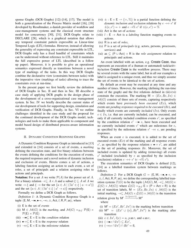
sponse Graphs (DCR Graphs) [12]–[14], [17]. The model isboth a generalization of the Process Matrix model [16], [18]developed by Resultmaker, a danish provider of workflow andcase-management systems and the classical event structuremodel for concurrency [30], [31]. DCR Graphs relate toDECLARE [28], which is a graphical notation that allowsany temporal constraint pattern expressible as Linear-timeTemporal Logic (LTL) formulas. However, instead of allowingthe generality of expressing any constraint expressible in LTL,DCR Graphs only has a fixed handful of constraints whichcan be understood without reference to LTL. Still it maintainsthe full expressive power of LTL (described in a followup paper). Moreover, it is possible to give an operationalsemantics expressed directly as transitions between a noveltype of markings of the tasks. In this way DCR Graphscombine the declarative view (constraints between tasks) withthe imperative view (markings of tasks) allowing to trace theconstraints even at run-time.
In the present paper we first briefly review the definitionof DCR Graphs in Sec. II and then in Sec. III describe acase study of applying DCR graphs in the design phase ofthe development of a cross-organizational case managementsystem. In Sec. IV we briefly describe the current status ofour development of tools for supporting design, simulation andverification of DCR Graphs. Finally, in Sec. VI we outlinechallenges identified in the case study and the proposal forthe continued development of the DCR Graphs model, tech-nologies and tools to make them applicable to component andmodel based design of distributed process-aware informationsystems.
II. DYNAMIC CONDITION RESPONSE GRAPHS
A Dynamic Condition Response Graph as introduced in [13]and extended in [14] consists of a set of events, a markingdefining the execution state, and five binary relations betweenthe events defining the conditions for the execution of events,the required responses and a novel notion of dynamic inclusionand exclusion of events. Hereto comes a set of actions, alabeling function assigning an action to each event, a set ofroles, a set of principals and a relation assigning roles toactions and principals.Notation: For a set A we write P(A) for the power set of A.For a binary relation →⊆ A×A and a subset ξ ⊆ A of A wewrite → ξ and ξ → for the set {a ∈ A | (∃a′ ∈ ξ | a→ a′)}and the set {a ∈ A | (∃a′ ∈ ξ | a′ → a)} respectively.
Formally we define a DCR Graph as follows.Definition 1: A Dynamic Condition Response Graph is a
tuple (E,M,→•, •→,→�,±,Act, l,R,P, as), where
(i) E is the set of events(ii) M ∈ M(G) is the marking, and M(G) =def P(E) ×P(E)× P(E)
(iii) →•⊆ E× E is the condition relation(iv) •→⊆ E× E is the response relation(v) →�⊆ E× E is the milestone relation
(vi) ± : E × E ⇀ {+,%} is a partial function defining thedynamic inclusion and exclusion relations by e→+ e′ if±(e, e′) = + and e→% e′ if ±(e, e′) = %
(vii) Act is the set of actions(viii) l : E → Act is a labeling function mapping events to
actions.(ix) R is a set of roles,(x) P is a set of principals (e.g. actors, persons, processors,
services) and(xi) as ⊆ (P ∪ Act) × R is the role assignment relation to
principals and actions.An event labelled with an action, e.g. Create Case, thus
represents an execution of a (human or automated) task/activ-ity/action Create Case in the workflow process. There maybe several events with the same label, but in all our examples alabel is assigned to a unique event, and thus we simply assumethe set of events to be identical to the set of actions.
By default an event may be executed at any time and anynumber of times. However, the marking (defining the run-timestate of the graph) and the five relations defined in (iii)-(vi)constrain the execution. The marking M = (Ex,Re, In) ∈M(G) consists of three sets of events, capturing respectivelywhich events have previously been executed (Ex), whichevents are pending responses required to be executed (Re), andfinally which events are currently included (In). Only eventse ∈ In, i.e. that are currently included, can be executed, andonly if all currently included condition events e′, as specifiedby the condition relation e′ →• e, have been executed andno currently included events e′ which are milestones for e,as specified by the milestone relation e′ →� e, are pendingresponses.
When an event e is executed, it is added to the set ofexecuted events (Ex) of the marking and all response eventse′, as specified by the response relation e •→ e′, are addedto the set of pending responses Re. Moreover, the set ofincluded events is updated by adding (removing) all eventse′ included (excluded) by e as specified by the inclusion(exclusion) relation e→+ e′ (e→% e′).
The execution semantics of DCR Graphs is defined [12],[14] as a labelled transition system between markings asfollows.
Definition 2: For a DCR Graph G = (E,M,→•, •→,→�,±, l,Act,R,P, as), we define the corresponding labelled tran-sition systems T (G) to be the tuple (M(G),M,→⊆M(G)×L(G)×M(G)) where L(G) =def E× (P× Act× R) is theset of transition labels, M = (Ex,Re, In) ∈ M(G) is theinitial marking, →⊆M(G)×L(G)×M(G) is the transition
relation given by M′(e,(p,a,r))−−−−−−→ M′′
where(i) M′ = (Ex′, Re′, In′) is the marking before transition
(ii) M′′ = (Ex′ ∪ {e}, Re′′, In′′) is the marking aftertransition
(iii) e ∈ In′, l(e) = a, p as r, and a as r,(iv) (→•e ∩In′) ⊆ Ex′,(v) (→�e ∩In′) ∩Re′ = ∅,
49

(vi) In′′ = (In′ ∪ e→+) \ e→%,(vii) Re′′ = (Re′ \ {e}) ∪ e•→,We define a run (e0, (p0, a0, r0)), (e1, (p1, a1, r1)), . . . of thetransition system to be a sequence of labels of a sequenceof transitions Mi
(ei,(pi,ai,ri))−−−−−−−−−→ Mi+1 starting from the initialmarking. We define a run to be accepting if ∀i ≥ 0, e ∈Rei.∃j ≥ i.(e = ej ∨e 6∈ Inj+1). In words, a run is acceptingif no response event is pending forever, i.e. it must eitherhappen at some later state or become excluded.Condition (iii) in the above definition expresses that, onlyevents e that are currently included, can be executed, and togive the label (p, a, r) the label of the event must be a, pmust be assigned to the role r, which must be assigned toa. Condition (iv) requires that all condition events to e whichare currently included should have been executed previously.Condition (v) states that the currently included events whichare milestones to event e must not be in the set of pendingresponses (Re′). Condition (vi) and (vii) are the updates tothe sets of included events and pending responses respectively.Note that an event e′ can not be both included and excluded bythe same event e, but an event may trigger itself as a response.
In this paper we only consider finite runs. In this case, theacceptance condition degenerates to requiring that no pendingresponse is included at the end of the run. This correspondsto defining all states where Re ∩ In = ∅ to be acceptingstates and define the accepting runs to be those ending inan accepting state. Infinite runs are also of interest especiallyin the context of reactive systems and the LTL logic. Theexecution semantics and acceptance condition for infinite runsare captured by mapping to a Buchi-automaton with τ -eventas formalized in [12], [17].
During the case study (Sec. III), we realized the need toextend our model with nested sub-graphs to allow for modelingof hierarchical sub structures. To address this need, so-calledNested DCR Graphs were introduced in [14]. It can be definedas an incremental extension to DCR Graph given in Def. 1above as follows.
Definition 3: A Nested dynamic condition response graphis a tuple (E,B,M,→•, •→,→�,±,Act, l,R,P, as), whereB : E⇀ E is a partial function mapping an event to its super-event (if defined) and (E,M,→•, •→,→�,±,Act, l,R,P, as)is a DCR Graph, subject to the condition that the markingM = (Ex,Re, In) ⊆ atoms(E)×atoms(E)×atoms(E) whereatoms(E) = {e | ∀e′ ∈ E. B (e′) 6= e} is the set of atomicevents.A nested DCR Graph can be mapped to a flat DCR Graphby extending all relations to the sub events and by preservingonly the atomic events. This flattening of a nested DCR Graphinto a DCR Graph is defined formally in [14]. In particular, thesemantics of a Nested DCR Graph is given as the labelled tran-sition semantics for its corresponding flattened DCR Graph.
III. CASE STUDY: A CROSS-ORGANIZATIONAL CASEMANAGEMENT SYSTEM
In this section we demonstrate how we have applied DCRGraphs in practice within a project that our industrial partner
Exformatics carried out for one of their customers. In theprocess, we acted as consultants, applying DCR Graphs inmeetings with Exformatics and the customer to capture therequirements in a declarative way, accompanying the usualUML sequence diagrams and prototype mock-ups. Sequencediagrams typically only describe examples of runs, and evenif they are extended with loops and conditional flows they donot capture the constraints explicitly.
The customer of the system is Landsorganisationen i Dan-mark (LO), which is the overarching organization for most ofthe trade unions in Denmark. Their counterpart is Dansk Ar-bejdsgiverforening (DA), which is an overarching organizationfor most of the Danish employers organizations.
At the top level, the workflow to be supported is that acase worker at the trade union must be able to create a case,e.g. triggered by a complaint by a member of the trade unionagainst her employer. This must be followed up by a meetingarranged by LO and subsequently held between case workersat the trade union, LO and DA. After being created, thecase can at any time be managed, e.g. adding or retrievingdocuments, by case workers at any of the organizations.
Fig. 1 shows the graphical representation of a simple DCRGraph capturing these top level requirements of our case study.
Figure 1. Top level requirements as a DCR Graph
Four top-level events were identified, shown as boxes inthe graph labelled Create case, Manage case, Arrangemeeting and Hold meeting. For the top-level events weidentified the following requirements:
1) A case is created by a union case worker, and only once.2) The case can be managed at the union, LO and DA after
it has been created.3) After a case is created, LO can and must arrange a
meeting between the union case worker, the LO caseworker and the DA case worker.
4) After a meeting is arranged it must be held (organizedby LO).
The requirements translate to the following DCR Graph roleassignments (shown as ”ears” on the event boxes) and relationsshown as different types of arrows between the events in Fig.1:
50
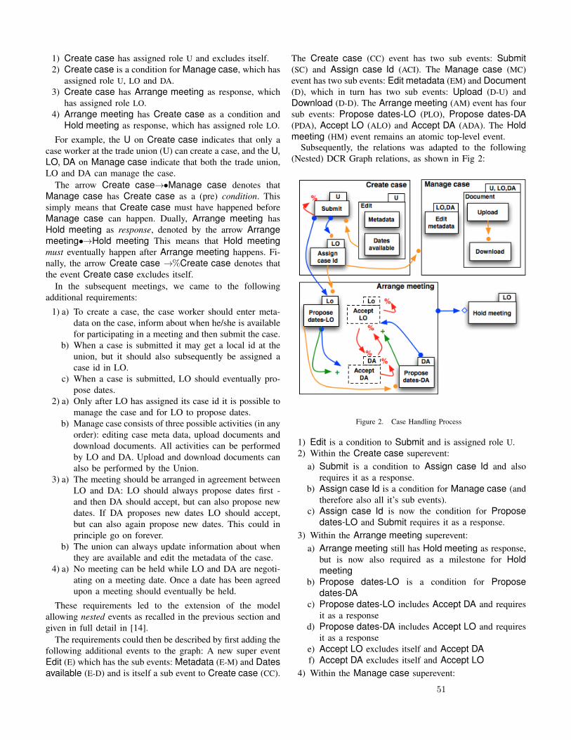
1) Create case has assigned role U and excludes itself.2) Create case is a condition for Manage case, which has
assigned role U, LO and DA.3) Create case has Arrange meeting as response, which
has assigned role LO.4) Arrange meeting has Create case as a condition and
Hold meeting as response, which has assigned role LO.
For example, the U on Create case indicates that only acase worker at the trade union (U) can create a case, and the U,LO, DA on Manage case indicate that both the trade union,LO and DA can manage the case.
The arrow Create case→•Manage case denotes thatManage case has Create case as a (pre) condition. Thissimply means that Create case must have happened beforeManage case can happen. Dually, Arrange meeting hasHold meeting as response, denoted by the arrow Arrangemeeting•→Hold meeting This means that Hold meetingmust eventually happen after Arrange meeting happens. Fi-nally, the arrow Create case →%Create case denotes thatthe event Create case excludes itself.
In the subsequent meetings, we came to the followingadditional requirements:
1) a) To create a case, the case worker should enter meta-data on the case, inform about when he/she is availablefor participating in a meeting and then submit the case.
b) When a case is submitted it may get a local id at theunion, but it should also subsequently be assigned acase id in LO.
c) When a case is submitted, LO should eventually pro-pose dates.
2) a) Only after LO has assigned its case id it is possible tomanage the case and for LO to propose dates.
b) Manage case consists of three possible activities (in anyorder): editing case meta data, upload documents anddownload documents. All activities can be performedby LO and DA. Upload and download documents canalso be performed by the Union.
3) a) The meeting should be arranged in agreement betweenLO and DA: LO should always propose dates first -and then DA should accept, but can also propose newdates. If DA proposes new dates LO should accept,but can also again propose new dates. This could inprinciple go on forever.
b) The union can always update information about whenthey are available and edit the metadata of the case.
4) a) No meeting can be held while LO and DA are negoti-ating on a meeting date. Once a date has been agreedupon a meeting should eventually be held.
These requirements led to the extension of the modelallowing nested events as recalled in the previous section andgiven in full detail in [14].
The requirements could then be described by first adding thefollowing additional events to the graph: A new super eventEdit (E) which has the sub events: Metadata (E-M) and Datesavailable (E-D) and is itself a sub event to Create case (CC).
The Create case (CC) event has two sub events: Submit(SC) and Assign case Id (ACI). The Manage case (MC)event has two sub events: Edit metadata (EM) and Document(D), which in turn has two sub events: Upload (D-U) andDownload (D-D). The Arrange meeting (AM) event has foursub events: Propose dates-LO (PLO), Propose dates-DA(PDA), Accept LO (ALO) and Accept DA (ADA). The Holdmeeting (HM) event remains an atomic top-level event.
Subsequently, the relations was adapted to the following(Nested) DCR Graph relations, as shown in Fig 2:
Figure 2. Case Handling Process
1) Edit is a condition to Submit and is assigned role U.2) Within the Create case superevent:
a) Submit is a condition to Assign case Id and alsorequires it as a response.
b) Assign case Id is a condition for Manage case (andtherefore also all it’s sub events).
c) Assign case Id is now the condition for Proposedates-LO and Submit requires it as a response.
3) Within the Arrange meeting superevent:a) Arrange meeting still has Hold meeting as response,
but is now also required as a milestone for Holdmeeting
b) Propose dates-LO is a condition for Proposedates-DA
c) Propose dates-LO includes Accept DA and requiresit as a response
d) Propose dates-DA includes Accept LO and requiresit as a response
e) Accept LO excludes itself and Accept DAf) Accept DA excludes itself and Accept LO
4) Within the Manage case superevent:
51
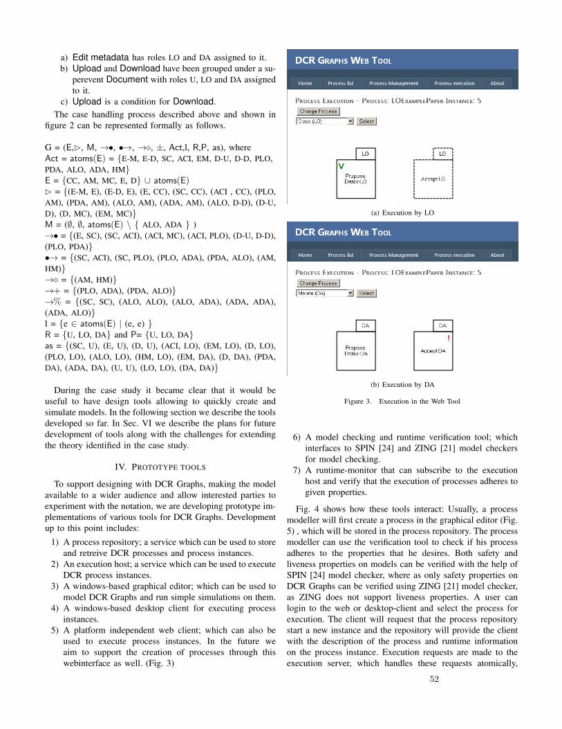
a) Edit metadata has roles LO and DA assigned to it.b) Upload and Download have been grouped under a su-
perevent Document with roles U, LO and DA assignedto it.
c) Upload is a condition for Download.The case handling process described above and shown in
figure 2 can be represented formally as follows.
G = (E,B, M, →•, •→, →�, ±, Act,l, R,P, as), whereAct = atoms(E) = {E-M, E-D, SC, ACI, EM, D-U, D-D, PLO,PDA, ALO, ADA, HM}E = {CC, AM, MC, E, D} ∪ atoms(E)B = {(E-M, E), (E-D, E), (E, CC), (SC, CC), (ACI , CC), (PLO,AM), (PDA, AM), (ALO, AM), (ADA, AM), (ALO, D-D), (D-U,D), (D, MC), (EM, MC)}M = (∅, ∅, atoms(E) \ { ALO, ADA } )→• = {(E, SC), (SC, ACI), (ACI, MC), (ACI, PLO), (D-U, D-D),(PLO, PDA)}•→ = {(SC, ACI), (SC, PLO), (PLO, ADA), (PDA, ALO), (AM,HM)}→� = {(AM, HM)}→+ = {(PLO, ADA), (PDA, ALO)}→% = {(SC, SC), (ALO, ALO), (ALO, ADA), (ADA, ADA),(ADA, ALO)}l = {e ∈ atoms(E) | (e, e) }R = {U, LO, DA} and P= {U, LO, DA}as = {(SC, U), (E, U), (D, U), (ACI, LO), (EM, LO), (D, LO),(PLO, LO), (ALO, LO), (HM, LO), (EM, DA), (D, DA), (PDA,DA), (ADA, DA), (U, U), (LO, LO), (DA, DA)}
During the case study it became clear that it would beuseful to have design tools allowing to quickly create andsimulate models. In the following section we describe the toolsdeveloped so far. In Sec. VI we describe the plans for futuredevelopment of tools along with the challenges for extendingthe theory identified in the case study.
IV. PROTOTYPE TOOLS
To support designing with DCR Graphs, making the modelavailable to a wider audience and allow interested parties toexperiment with the notation, we are developing prototype im-plementations of various tools for DCR Graphs. Developmentup to this point includes:
1) A process repository; a service which can be used to storeand retreive DCR processes and process instances.
2) An execution host; a service which can be used to executeDCR process instances.
3) A windows-based graphical editor; which can be used tomodel DCR Graphs and run simple simulations on them.
4) A windows-based desktop client for executing processinstances.
5) A platform independent web client; which can also beused to execute process instances. In the future weaim to support the creation of processes through thiswebinterface as well. (Fig. 3)
(a) Execution by LO
(b) Execution by DA
Figure 3. Execution in the Web Tool
6) A model checking and runtime verification tool; whichinterfaces to SPIN [24] and ZING [21] model checkersfor model checking.
7) A runtime-monitor that can subscribe to the executionhost and verify that the execution of processes adheres togiven properties.
Fig. 4 shows how these tools interact: Usually, a processmodeller will first create a process in the graphical editor (Fig.5) , which will be stored in the process repository. The processmodeller can use the verification tool to check if his processadheres to the properties that he desires. Both safety andliveness properties on models can be verified with the help ofSPIN [24] model checker, where as only safety properties onDCR Graphs can be verified using ZING [21] model checker,as ZING does not support liveness properties. A user canlogin to the web or desktop-client and select the process forexecution. The client will request that the process repositorystart a new instance and the repository will provide the clientwith the description of the process and runtime informationon the process instance. Execution requests are made to theexecution server, which handles these requests atomically,
52
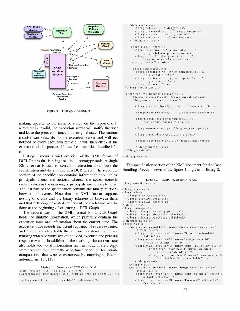
Figure 4. Protoype Architecture
making updates to the instance stored on the repository. Ifa request is invalid, the execution server will notify the userand leave the process instance in its original state. The runtimemonitor can subscribe to the execution server and will getnotified of every execution request. It will then check if theexecution of the process follows the properties described forit.
Listing 1 shows a brief overview of the XML format ofDCR Graphs that is being used in all prototype tools. A singleXML format is used to contain information about both thespecification and the runtime of a DCR Graph. The resourcessection of the specification contains information about roles,principals, events and actions, whereas the access controlssection contains the mapping of principals and actions to roles.The last part of the specification contains the binary relationsbetween the events. Note that the XML format supportsnesting of events and the binary relations in between themand that flattening of nested events and their relations will bedone at the beginning of executing a DCR Graph.
The second part of the XML format for a DCR Graphholds the runtime information, which primarily contains theexecution trace and information about the current state. Theexecution trace records the actual sequence of events executedand the current state holds the information about the currentmarking which contains sets of included, executed and pendingresponse events. In addition to the marking, the current statealso holds additional information such as index of state copy,state accepted to support the acceptance condition for infinitecomputations that were characterized by mapping to Buchi-automata in [12], [17].
Listing 1. Overview of DCR Graph Xml<? xml v e r s i o n =” 1 . 0 ” e n c o d i n g =” u t f−8” ?><d c r g : p r o c e s s x m l n s : d c r g =” h t t p : / / i t u . dk / t r u s t c a r e / d c r / 2 0 1 1 / ”>
<d c r g : s p e c i f i c a t i o n p r o c e s s I d =” ” modelName=” ”>
<d c r g : r e s o u r c e s><d c r g : r o l e s> . . . . .</ d c r g : r o l e s><d c r g : p r i n c i p a l s> . . . . .</ d c r g : p r i n c i p a l s><d c r g : e v e n t s> . . . . .</ d c r g : e v e n t s><d c r g : a c t i o n s> . . . . .</ d c r g : a c t i o n s>
</ d c r g : r e s o u r c e s>
<d c r g : a c c e s s C o n t r o l s><d c r g : r o l e P r i n c i p a l A s s i g n m e n t s> . . . . .</
d c r g : r o l e P r i n c i p a l A s s i g n m e n t s><d c r g : a c t i o n R o l e A s s i g n m e n t s> . . . . .</
d c r g : a c t i o n R o l e A s s i g n m e n t s></ d c r g : a c c e s s C o n t r o l s>
<d c r g : c o n s t r a i n t S e t s><d c r g : c o n s t r a i n t S e t t y p e =” c o n d i t i o n ”> . . .</
d c r g : c o n s t r a i n t S e t><d c r g : c o n s t r a i n t S e t t y p e =” r e s p o n s e ”> . . .</
d c r g : c o n s t r a i n t S e t> . . . . .</ d c r g : c o n s t r a i n t S e t s>
</ d c r g : s p e c i f i c a t i o n>
<d c r g : r u n t i m e p r o c e s s I n s t a n c e I d =” ”><d c r g : e x e c u t i o n T r a c e> </ d c r g : e x e c u t i o n T r a c e><d c r g : c u r r e n t S t a t e s t a t e I d =” ”>
<d c r g : e v e n t s I n c l u d e d> . . . . .</ d c r g : e v e n t s I n c l u d e d>
<d c r g : e v e n t s E x e c u t e d> . . . . .</ d c r g : e v e n t s E x e c u t e d>
<d c r g : e v e n t s P e n d i n g R e s p o n s e s> . . . . .</d c r g : e v e n t s P e n d i n g R e s p o n s e s>
<d c r g : s t a t e A c c e p t i n g> </ d c r g : s t a t e A c c e p t i n g>
<d c r g : s t a t e I n d e x> </ d c r g : s t a t e I n d e x>
<d c r g : e v e n t s E n a b l e d> . . . . .</ d c r g : e v e n t s E n a b l e d>
</ d c r g : c u r r e n t S t a t e></ d c r g : r u n t i m e>
</ d c r g : p r o c e s s>
The specification section of the XML document for the CaseHandling Process shown in the figure 2 is given in listing 2.
Listing 2. DCRG specification in Xml<d c r g : s p e c i f i c a t i o n>
<d c r g : r e s o u r c e s><d c r g : r o l e s>
<d c r g : r o l e>U</ d c r g : r o l e><d c r g : r o l e>LO</ d c r g : r o l e><d c r g : r o l e>DA</ d c r g : r o l e>
</ d c r g : r o l e s><d c r g : p r i n c i p a l s>
<d c r g : p r i n c i p a l>u</ d c r g : p r i n c i p a l><d c r g : p r i n c i p a l>l o</ d c r g : p r i n c i p a l><d c r g : p r i n c i p a l>da</ d c r g : p r i n c i p a l>
</ d c r g : p r i n c i p a l s><d c r g : e v e n t s>
<d c r g : e v e n t e v e n t I d =” 0 ” name=” C r e a t e c a s e ” a c t i o n I d =”C r e a t e c a s e ”>
<d c r g : e v e n t e v e n t I d =” 1 ” name=” Submit ” a c t i o n I d =”Submit ” />
<d c r g : e v e n t e v e n t I d =” 2 ” name=” Ass ign c a s e Id ”a c t i o n I d =” Ass ign c a s e Id ” />
<d c r g : e v e n t e v e n t I d =” 3 ” name=” E d i t ” a c t i o n I d =” E d i t ”><d c r g : e v e n t e v e n t I d =” 4 ” name=” Metada ta ”
a c t i o n I d =” Metada ta ” /><d c r g : e v e n t e v e n t I d =” 5 ” name=” Dates a v a i l a b l e
” a c t i o n I d =” Da tes a v a i l a b l e ” /></ d c r g : e v e n t>
</ d c r g : e v e n t><d c r g : e v e n t e v e n t I d =” 6 ” name=” Manage c a s e ” a c t i o n I d =”
Manage c a s e ”><d c r g : e v e n t e v e n t I d =” 7 ” name=” E d i t m e t a d a t a ” a c t i o n I d
=” E d i t m e t a d a t a ” /><d c r g : e v e n t e v e n t I d =” 8 ” name=” Document ” a c t i o n I d =”
Document ”>
53

<d c r g : e v e n t e v e n t I d =” 9 ” name=” Upload ”a c t i o n I d =” Upload ” />
<d c r g : e v e n t e v e n t I d =” 10 ” name=” Download ”a c t i o n I d =” Download ” />
</ d c r g : e v e n t></ d c r g : e v e n t><d c r g : e v e n t e v e n t I d =” 11 ” name=” Arrange Meet ing ” a c t i o n I d
=” Submit ”><d c r g : e v e n t e v e n t I d =” 12 ” name=” Propose d a t e s−LO”
a c t i o n I d =” Propose d a t e s−LO” /><d c r g : e v e n t e v e n t I d =” 13 ” name=” Accept LO” a c t i o n I d =”
Accept LO” /><d c r g : e v e n t e v e n t I d =” 14 ” name=” Accept DA” a c t i o n I d =”
Accept DA” /><d c r g : e v e n t e v e n t I d =” 15 ” name=” Propose d a t e s−DA”
a c t i o n I d =” Propose d a t e s−DA” /></ d c r g : e v e n t><d c r g : e v e n t e v e n t I d =” 16 ” name=” Hold mee t ing ” a c t i o n I d =”
Hold mee t ing ” /></ d c r g : e v e n t s><d c r g : a c t i o n s>
<d c r g : a c t i o n a c t i o n I d =” C r e a t e c a s e ” /><d c r g : a c t i o n a c t i o n I d =” Submit ” /><d c r g : a c t i o n a c t i o n I d =” E d i t ” /><d c r g : a c t i o n a c t i o n I d =” Metada ta ” /><d c r g : a c t i o n a c t i o n I d =” Da tes a v a i l a b l e ” /> . . . .
</ d c r g : a c t i o n s></ d c r g : r e s o u r c e s><d c r g : a c c e s s C o n t r o l s>
<d c r g : r o l e P r i n c i p a l A s s i g n m e n t s><d c r g : r o l e P r i n c i p a l A s s i g n m e n t r o l e−name=”U”>
<p r i n c i p a l>u</ p r i n c i p a l></ d c r g : r o l e P r i n c i p a l A s s i g n m e n t><d c r g : r o l e P r i n c i p a l A s s i g n m e n t r o l e−name=”LO”>
<p r i n c i p a l>l o</ p r i n c i p a l></ d c r g : r o l e P r i n c i p a l A s s i g n m e n t>
</ d c r g : r o l e P r i n c i p a l A s s i g n m e n t s><d c r g : a c t i o n R o l e A s s i g n m e n t s>
<d c r g : a c t i o n R o l e A s s i g n m e n t a c t i o n I d =” Submit ”><d c r g : r o l e>U</ d c r g : r o l e>
</ d c r g : a c t i o n R o l e A s s i g n m e n t><d c r g : a c t i o n R o l e A s s i g n m e n t a c t i o n I d =” Document ”>
<d c r g : r o l e>U</ d c r g : r o l e><d c r g : r o l e>LO</ d c r g : r o l e><d c r g : r o l e>DA</ d c r g : r o l e>
</ d c r g : a c t i o n R o l e A s s i g n m e n t> . . . .</ d c r g : a c t i o n R o l e A s s i g n m e n t s>
</ d c r g : a c c e s s C o n t r o l s><d c r g : c o n s t r a i n t S e t s>
<d c r g : c o n s t r a i n t S e t t y p e =” c o n d i t i o n ”><d c r g : c o n s t r a i n t s o u r c e =” 1 ” t a r g e t =” 2 ” /><d c r g : c o n s t r a i n t s o u r c e =” 3 ” t a r g e t =” 1 ” /> . . . . .
</ d c r g : c o n s t r a i n t S e t><d c r g : c o n s t r a i n t S e t t y p e =” r e s p o n s e ”>
<d c r g : c o n s t r a i n t s o u r c e =” 1 ” t a r g e t =” 2 ” /> . . . . .</ d c r g : c o n s t r a i n t S e t> . . . . .
</ d c r g : c o n s t r a i n t S e t s>
</ d c r g : s p e c i f i c a t i o n>
All the prototype tools support the basic DCR Graphnotation containing condition, response, include and excluderelations. We are currently working on extending the prototypeto support milestone relations and nested events. In Fig. 6, 7, 8,we have illustrated how the execution state of the case-handling process may be visualized in the simulator in thefuture.
The graph in the figure. 6 shows the state after a run wherethe union started by creating a case: they edited meta-data,indicated the dates they were available and submitted. WhenLO received the case they assigned their own case ID to it.Some time later LO proposed possible dates for a meetingto DA. DA did not agree with these dates and responded byproposing some of their own. In the graph both Accept LOand Accept DA are included and have a pending responsebecause both LO and DA have proposed dates. Because of
Figure 5. The Graphical Editor
Figure 6. Case Handling Process Runtime
these pending responses Hold meeting is disabled. Becauseno files have been uploaded to the document yet, Downloadis also disabled. The listing 3 shows the runtime informationfor the case handling process from the figure 6.
Listing 3. DCRG Runtime in Xml<d c r g : r u n t i m e p r o c e s s I n s t a n c e I d =” ”>
<d c r g : e x e c u t i o n T r a c e>4 , 5 , 4 , 1 , 2 , 1 2 , 1 5</d c r g : e x e c u t i o n T r a c e>
<d c r g : c u r r e n t S t a t e s t a t e I d =” S6 ”>
54

<d c r g : e v e n t s I n c l u d e d>2 , 4 , 5 , 7 , 9 , 1 0 , 1 2 , 1 3 , 1 4 , 1 5 , 1 6</d c r g : e v e n t s I n c l u d e d>
<d c r g : e v e n t s E x e c u t e d>1 , 2 , 4 , 5 , 1 2 , 1 5</d c r g : e v e n t s E x e c u t e d>
<d c r g : e v e n t s P e n d i n g R e s p o n s e s>13 ,14 ,16</d c r g : e v e n t s P e n d i n g R e s p o n s e s>
<d c r g : s t a t e A c c e p t i n g>0</ d c r g : s t a t e A c c e p t i n g><d c r g : s t a t e I n d e x>0</ d c r g : s t a t e I n d e x><d c r g : e v e n t s E n a b l e d>1 , 2 , 4 , 5 , 7 , 8 , 1 2 , 1 3 , 1 4 , 1 5</
d c r g : e v e n t s E n a b l e d></ d c r g : c u r r e n t S t a t e>
</ d c r g : r u n t i m e>
The graph in the figure. 7 shows the runtime state after theunion has uploaded an agenda for the meetings. Note that,since the union has uploaded a file to the case, Download isnow enabled. But at the same time, Accept LO and AcceptDA still remain the same as the previous graph, as the proposeddates have not been accepted yet by either LO or DA.
Figure 7. Case Handling Process Runtime After Upload Document
Figure 8 shows the graph representing the state after LOhas accepted one of the dates proposed by DA. Note that bothAccept LO and Accept DA are excluded due to the mutualexclude relation between them. Even though there is a pendingresponse on Accept DA, it is not considered relevant as it isexcluded and Hold meeting has become pending because ofthe response relation. Continuing by executing Hold meetingas LO will cause the graph to reach an accepting state, as therewill be no included pending responses.
V. COMPARISON TO OTHER APPROACHES
As already mentioned in the introduction, our approach isclosely related to the work on DECLARE [27], [28]. In partic-ular the condition and response relations are also consideredin [27], [28], and we have used the same graphical notationas loc. cit. The crucial difference is that we focus on a fewcore constraints allowing to describe the state and operationalsemantics of processes as a labelled transitions between simple
Figure 8. Case Handling Process Runtime After Accept Dates
markings consisting of three sets of respectively executed,included and required events. As also pointed out in [27], [28],the generality of LTL offers much flexibility with respect tospecifying execution constraints but makes it more complexto execute processes given in DECLARE and to describeand understand their run-time state. It typically requires atranslation of the constraints to LTL and subsequent using thestandard mapping of an LTL formula to a Buchi-automaton.In particular, there is no obvious way to trace the graphicalconstraints in DECLARE to the states of the Buchi-automaton.Moreover, we show in a follow up paper that every set oftraces expressible in LTL (and thus DECLARE) can also beexpressed using DCR Graphs.
We have shown in [18] it is possible, but much morecomplex to represent in LTL the interplay between dynamicinclusion/exclusion and the other relations. Neither this novelnotion of dynamic inclusion/exclusion relations nor nesting areconsidered in [27], [28].
The DCR Graphs model also relates to the independentwork on the Guard-Stage-Milestone model [15] by Hull etal presented as an invited talk at the WS-FM 2010 workshopand part of the work on artifact-centric business processes [2],[5], [7].
Finally, BPMN 2.0 includes the ad-hoc sub-process activitywhich allows one to group a set of activities that can becarried out in an ad-hoc way. Fig. 9 below shows how onemay attempt to describe the top level requirements describedin Fig. 1 as a BPMN 2.0 ad-hoc sub-acitivity. According to theinformal description of BPMN 2.0 ad-hoc sub-process activityin the current BPMN 2.0 specification ( [19]) Create case isa condition for Manage case since the latter cannot startwithout the data object case as input, which is produced
55

Figure 9. BPMN 2.0 ad-hoc sub-process activity
by the former. Moreover, quoting from the specification, thesequence flow between Create case and Arrange meeting(and similarly between Arrange meeting and Hold meeting):”creates a dependency where the performance of the firstTask MUST be followed by a performance of the secondTask. This does not mean that the second Task is to beperformed immediately, but there MUST be a performanceof the second task after the performance of the first Task.”.This seems exactly to correspond to the response relation inDCR Graphs. However, when reading the semantics sectionof the specification ( [19], Sec.13.2.5, 445-446) it appearsthat the sequence flow introduces just a standard precondition.Thus, the specification is not consistent in the description ofsequence flows within ad-hoc sub-activities. Also, it is notclear how to specify roles on actions (swim lanes seem not tobe allowed within ad-hoc sub-activities) nor how to specifythat an activity within an ad-hoc sub activity only can beexecuted once. In particular, Create case can be executedany number of times in the above process.
VI. CONCLUSIONS AND FUTURE WORK
Our case study showed that the DCR Graphs model is wellsuited to give a global description of the temporal constraintsbetween the individual tasks which is helpful in capturing therequirements of the overall system.
However, there are still many points for future develop-ments.
First of all there is the need to extend the expressivenessof DCR Graphs. In the ongoing PhD project of the secondauthor we intend to extend the DCR Graphs model to beable to express relevant features such as multi-instance sub-graphs (allowing the dynamic creation of sub-graphs repre-senting dynamic sub process instantiation), time, exceptionsand data. Along with this we intend to continue developingthe technology for model checking and run time verificationand apply it within case studies.
Second, our industrial partner Resultmaker who alreadyuse a declarative process model based on the primitives inthe DCR Graphs model expects to investigate the use of theformalization to support safe dynamic changes to the processconstraints at run time.
Thirdly, the DCR Graphs model presently describe a globalview of the process. Through our discussions with Exformaticsduring the case study we identified the wish to be able toautomatically synthesize distributed views of the process. Inparticular, they wanted to be able to derive descriptions ofcommunication protocols and message exchange between theindividual local components in a distributed implementationof the system.
Derivations of descriptions of communication protocolsbetween local components from a global model is been re-searched for the imperative choreography language WS-CDLin the work on structured communication-centred program-ming for web services by Carbone, Honda and Yoshida [4].Put briefly, the work formalizes the core of WS-CDL as theglobal process calculus and define a formal theory of end pointprojections projecting the global process calculus to abstractdescriptions of the behavior of each of the local ”end-points”given as pi-calculus processes typed with session types.
We are currently working on the challenge of synthesizinga distributed view of a DCR Graph as a set of interactingDCR Graphs, thus providing a declarative notion of end-pointprojections. As a challenge for future work we propose toprovide a formal map between DCR Graphs and imperativechoreographies formalized in the global process calculus [4].
REFERENCES
[1] Active Endpoints, Adobe Systems, BEA Systems, IBM, Oracle,SAP. Ws-bpel extension for people (bpel4people) version 1.0,2007. http://www.adobe.us/content/dam/Adobe/en/devnet/livecycle/pdfs/bpel4people spec.pdf.
[2] Kamal Bhattacharya, Cagdas Gerede, Richard Hull, Rong Liu, andJianwen Su. Towards formal analysis of artifact-centric business processmodels. In In preparation, pages 288–304, 2007.
[3] Christoph Bussler and Stefan Jablonski. Implementing agent coordina-tion for workflow management systems using active database systems.In Research Issues in Data Engineering, 1994. Active Database Systems.Proceedings Fourth International Workshop on, pages 53–59, Feb 1994.
[4] Marco Carbone, Kohei Honda, and Nobuko Yoshida. StructuredCommunication-Centred Programming for Web Services. In 16thEuropean Symposium on Programming (ESOP’07), LNCS, pages 2–17.Springer, 2007.
[5] David Cohn and Richard Hull. Business artifacts: A data-centricapproach to modeling business operations and processes. IEEE DataEng. Bull., 32(3):3–9, 2009.
[6] Hasam Davulcu, Michael Kifer, C. R. Ramakrishnan, and I.V. Ramakr-ishnan. Logic based modeling and analysis of workflows. In Proceedingsof ACM SIGACT-SIGMOD-SIGART, pages 1–3. ACM Press, 1998.
[7] Alin Deutsch, Richard Hull, Fabio Patrizi, and Victor Vianu. Automaticverification of data-centric business processes. In Proceedings of the12th International Conference on Database Theory, ICDT ’09, pages252–267, New York, NY, USA, 2009. ACM.
[8] Marlon Dumas, Wil M. van der Aalst, and Arthur H. ter Hofstede.Process Aware Information Systems: Bridging People and SoftwareThrough Process Technology. Wiley-Interscience, 2005.
[9] Clarence A. Ellis and Gary J. Nutt. Office information systems andcomputer science. ACM Comput. Surv., 12:27–60, March 1980.
[10] Clarence A. Ellis and Gary J. Nutt. Workflow: The Process Spectrum.In Amit Sheth, editor, Proceedings of the NSF Workshop on Workflowand Process Automation in Information Systems, pages 140–145, May1996.
[11] Thomas Hildebrandt. Trustworthy pervasive healthcare processes (Trust-Care) research project. Webpage, 2008. http://www.trustcare.dk/.
[12] Thomas Hildebrandt and Raghava Rao Mukkamala. Declarative event-based workflow as distributed dynamic condition response graphs. InPost-proceedings of PLACES 2010, 2010.
56
[13] Thomas Hildebrandt and Raghava Rao Mukkamala. Distributed dynamiccondition response structures. In Pre-proceedings of InternationalWorkshop on Programming Language Approaches to Concurrency andCommunication-cEntric Software (PLACES 10), March 2010.
[14] Thomas Hildebrandt, Raghava Rao Mukkamala, and Tijs Slaats. Nesteddynamic condition response graphs. In Fundamentals of SoftwareEngineering Confereence 2011 (to appear), April 2011.
[15] Richard Hull. Formal study of business entities with lifecycles: Usecases, abstract models, and results. In Proceedings of 7th InternationalWorkshop on Web Services and Formal Methods, volume 6551 of LectureNotes in Computer Science, 2010.
[16] Karen Marie Lyng, Thomas Hildebrandt, and Raghava Rao Mukkamala.From paper based clinical practice guidelines to declarative workflowmanagement. In Proceedings ProHealth 08 workshop, 2008.
[17] Raghava Rao Mukkamala and Thomas Hildebrandt. From dynamiccondition response structures to buchi automata. In Proceedings of4th IEEE International Symposium on Theoretical Aspects of SoftwareEngineering (TASE 2010), August 2010.
[18] Raghava Rao Mukkamala, Thomas Hildebrandt, and Janus Boris Tøth.The resultmaker online consultant: From declarative workflow manage-ment in practice to LTL. In Proceeding of DDBP, 2008.
[19] Object Management Group BPMN Technical Committee. BusinessProcess Model and Notation, version 2.0, 2010. http://www.omg.org/spec/BPMN/2.0/.
[20] Organization for the Advancement of Structured Information Standards(OASIS). Web services human task (ws-humantask) specification, ver-sion 1.1, 2009. http://docs.oasis-open.org/bpel4people/ws-humantask-1.1-spec-cd-06.pdf.
[21] Microsoft Research. Zing model checker. Webpage, 2010. http://research.microsoft.com/en-us/projects/zing/.
[22] Pinar Senkul, Michael Kifer, and Ismail H. Toroslu. A logical frameworkfor scheduling workflows under resource allocation constraints. In InVLDB, pages 694–705, 2002.
[23] Munindar P. Singh, Greg Meredith, Christine Tomlinson, and Paul C.Attie. An event algebra for specifying and scheduling workflows. InProceedings of DASFAA, pages 53–60. World Scientific Press, 1995.
[24] Spin. On-the-fly, ltl model checking with spin. Webpage, 2008. http://spinroot.com/spin/whatispin.html.
[25] Keith D. Swenson. Mastering the Unpredictable: How Adaptive CaseManagement Will Revolutionize the Way That Knowledge Workers GetThings Done. Meghan-Kiffer Press, 2010.
[26] Wil M. P. van der Aalst and S Jablonski. Dealing with workflow change:Identification of issues and solutions. International Journal of ComputerSystems, Science, and Engineering, 15(5):267–276, 2000.
[27] Wil M. P. van der Aalst, Maja Pesic, and Helen Schonenberg. Declarativeworkflows: Balancing between flexibility and support. Computer Science- R&D, 23(2):99–113, 2009.
[28] Wil M.P van der Aalst and Maja Pesic. A declarative approach forflexible business processes management. In Proceedings DPM 2006,LNCS. Springer Verlag, 2006.
[29] W3C. Web services choreography description language, version 1.0,2005. http://www.w3.org/TR/ws-cdl-10/.
[30] Glynn Winskel. Event structures. In Wilfried Brauer, Wolfgang Reisig,and Grzegorz Rozenberg, editors, Advances in Petri Nets, volume 255of Lecture Notes in Computer Science, pages 325–392. Springer, 1986.
[31] Glynn Winskel and Mogens Nielsen. Models for concurrency. pages1–148, 1995.
[32] M. D. Zisman. Representation, Specification and Automation of OfficeProcedures. Philadelphia, Pa.: University of Pennsylvania, WhartonSchool, Department of Decision Sciences, Ph.D. Thesis, Sep, 1977.
57
Hierarchical Declarative Modelling withRefinement and Sub-processes
Søren Debois1, Thomas Hildebrandt1, and Tijs Slaats1,2
1 IT University of Copenhagen, Rued Langgaardsvej 7, 2300 Copenhagen, Denmark{debois,hilde,tslaats}@itu.dk
2 Exformatics A/S, Lautrupsgade 13, 2100 Copenhagen, Denmark
Abstract. We present a new declarative model with composition andhierarchical definition of processes, featuring (a) incremental refinement,(b) adaptation of processes, and (c) dynamic creation of sub-processes.The approach is motivated and exemplified by a recent case manage-ment solution delivered by our industry partner Exformatics A/S. Theapproach is achieved by extending the Dynamic Condition Response(DCR) graph model with interfaces and composition along those inter-faces. Both refinement and sub-processes are then constructed in terms ofthat composition. Sub-processes take the form of hierarchical (complex)events, which dynamically instantiate sub-processes. The extensions arerealised and supported by a prototype simulation tool.
1 Introduction
Business process design technologies today are predominantly based on flow-oriented process notations such as the Business Process Model and Notation(BPMN) standard [18], which imperatively describes how a process should pro-ceed from start to end. Often, business processes are required to be compliantwith regulations and constraints given by busines polices, standards and laws.E.g., a customer must be informed about alternatives and risks before getting aloan in a bank, or a decision on a grant application cannot be made before thedeadline for submissions of applications has been reached.
Since the flow-oriented notations only captures how to fulfill the compliancerules, the description and verification of compliance rules require other notationsand techniques. This leaves the process designers with three modelling tasks:To describe the compliance rules, to describe the process, and to verify thatthe process is compliant to the rules. Typically, compliance rules are describeddeclaratively using a variant of temporal logic such as Linear-time TemporalLogic (LTL) [21]. Compliance can then be verified during execution using run-time verification techniques [12] and, if the flow-diagrams are based on a formalmodel, also at design time [6]. In most industrial design tools, the flow-diagramsare however not based on a formal model, and consequently, design time verifi-cation is not supported. This means that the process designers have to figure outmanually how to interpret the constraints, and compliance is then subsequently
58
verified informally and approved by, e.g., a lawyer. At best, a formal run-timeor post-execution verification is performed against the execution log.
In these situations there is a high risk that processes become either non-compliant or over-constrained by design, to faciliate manual verification. Over-constrained processes, however, rarely fits reality or are simply not suitable forknowledge-intensive processes. A way to avoid these problems is to use the declar-ative approach (also) for the process design. Several declarative process mod-elling notations and techniques have been proposed in the last decade, includ-ing DECLARE [2,1], CLIMB [13], GSM [11] and Dynamic Condition Response(DCR) graphs [8,14]. However, sometimes the declarative approach makes it lessclear from the end-user, how a process will proceed from start to end. Evenwith a graphical notation (as in DECLARE, GSM and DCR graphs), it may bedifficult to comprehend the interactions between different constraints.
The DCR graph process modelling notation stands out by supporting a sim-ple and efficient run-time execution, which mitigates the complexity of com-prehending the constraints and allows for run-time adaptation [15], while stillbeing more expressive than (propositional) LTL (and thus DECLARE), in thatit allows to describe every union of a regular and an ω-regular language [3,16,14].
DCR Graphs were conceived as both a generalization of event structures [22]and a formalization and generalization of the Process Matrix [17] invented byDanish company Resultmaker. Since its inception, the DCR Graph notationand theory have been developed further in collaboration with Exformatics A/S,a Danish provider of case, document and knowledge management systems. A ver-sion of DCR graphs with a simple notion of nesting [9], an additional milestonerelation, and support for data now forms the core their workflow engine [20,7].However, DCR graph models as currently implemented become difficult to com-prehend and present at a certain size. They seem to lack encapsulation, mod-ularity and hierarchy; the key techniques to make large models comprehensiblein both imperative [19] and declarative settings [23]. Also, practical modellingefforts by Exformatics A/S has revealed that DCR graphs emphatically needs anotion of “dynamically created” or “instantiated” sub-process.
In the present paper, we seek to remedy these shortcomings of DCR graphs.Our contributions are as follows.
1. We introduce refinement-by-composition for DCR graphs.
2. We add to DCR graphs a notion of dynamically spawned sub-process, definingHi-DCR graphs.
3. We demonstrate the use of both incremental process design using an exampleexctracted from a recent case management solution delivered by ExformaticsA/S to a Danish funding agency.
4. We provide a publicly available Hi-DCR graph tool.
The tool allows simulation, model-checking of the finite fragment, automaticvisualisation and more. The compositions and refinements presented in exampleswere not made by hand, they were executed by the tool; all DCR diagrams inthis paper has been generated by it, and all examples are fully executable by it.
59
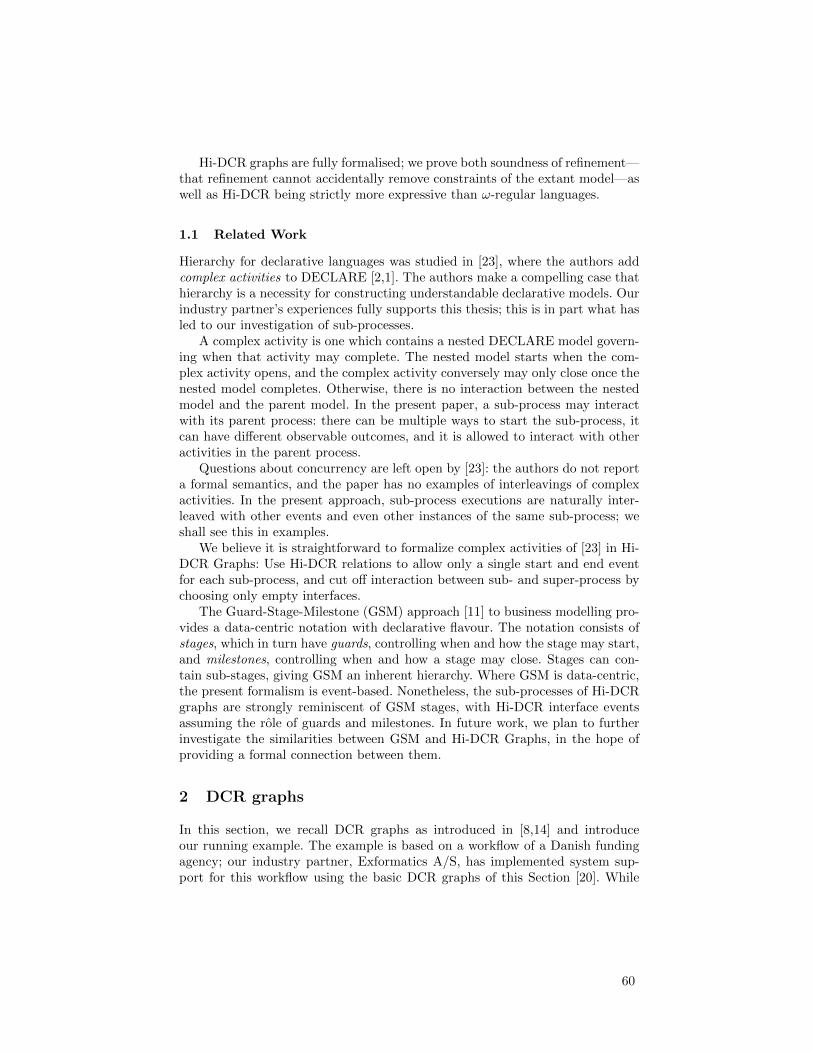
Hi-DCR graphs are fully formalised; we prove both soundness of refinement—that refinement cannot accidentally remove constraints of the extant model—aswell as Hi-DCR being strictly more expressive than ω-regular languages.
1.1 Related Work
Hierarchy for declarative languages was studied in [23], where the authors addcomplex activities to DECLARE [2,1]. The authors make a compelling case thathierarchy is a necessity for constructing understandable declarative models. Ourindustry partner’s experiences fully supports this thesis; this is in part what hasled to our investigation of sub-processes.
A complex activity is one which contains a nested DECLARE model govern-ing when that activity may complete. The nested model starts when the com-plex activity opens, and the complex activity conversely may only close once thenested model completes. Otherwise, there is no interaction between the nestedmodel and the parent model. In the present paper, a sub-process may interactwith its parent process: there can be multiple ways to start the sub-process, itcan have different observable outcomes, and it is allowed to interact with otheractivities in the parent process.
Questions about concurrency are left open by [23]: the authors do not reporta formal semantics, and the paper has no examples of interleavings of complexactivities. In the present approach, sub-process executions are naturally inter-leaved with other events and even other instances of the same sub-process; weshall see this in examples.
We believe it is straightforward to formalize complex activities of [23] in Hi-DCR Graphs: Use Hi-DCR relations to allow only a single start and end eventfor each sub-process, and cut off interaction between sub- and super-process bychoosing only empty interfaces.
The Guard-Stage-Milestone (GSM) approach [11] to business modelling pro-vides a data-centric notation with declarative flavour. The notation consists ofstages, which in turn have guards, controlling when and how the stage may start,and milestones, controlling when and how a stage may close. Stages can con-tain sub-stages, giving GSM an inherent hierarchy. Where GSM is data-centric,the present formalism is event-based. Nonetheless, the sub-processes of Hi-DCRgraphs are strongly reminiscent of GSM stages, with Hi-DCR interface eventsassuming the role of guards and milestones. In future work, we plan to furtherinvestigate the similarities between GSM and Hi-DCR Graphs, in the hope ofproviding a formal connection between them.
2 DCR graphs
In this section, we recall DCR graphs as introduced in [8,14] and introduceour running example. The example is based on a workflow of a Danish fundingagency; our industry partner, Exformatics A/S, has implemented system sup-port for this workflow using the basic DCR graphs of this Section [20]. While
60
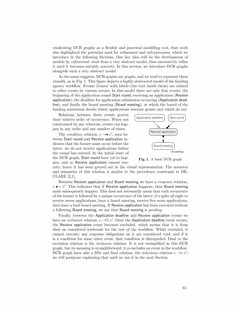
vindicating DCR graphs as a flexible and practical modelling tool, that workalso highlighted the potential need for refinement and sub-processes, which weintroduce in the following Sections. One key idea will be the development ofmodels by refinement : start from a very abstract model, then successively refineit until it becomes suitably concrete. In this section, we introduce DCR graphsalongside such a very abstract model.
As the name suggests, DCR graphs are graphs, and we tend to represent themvisually, as in Fig. 1. This figure depicts a highly abstracted model of the fundingagency workflow. Events (boxes) with labels (the text inside them) are relatedto other events by various arrows. In this model there are only four events: thebeginning of the application round Start round; receiving an application (Receiveapplication); the deadline for application submission occurring (Application dead-line); and finally the board meeting (Board meeting), at which the board of thefunding institution decide which applications warrant grants and which do not.
(Accepting)
Application deadline
Receive application
%
Board meeting
Start round
Fig. 1. A basic DCR graph
Relations between these events governtheir relative order of occurrence. When notconstrained by any relations, events can hap-pen in any order and any number of times.
The condition relation, e →• e′, seen be-tween Start round and Receive application in-dicates that the former must occur before thelatter: we do not receive applications beforethe round has started. In the initial state ofthe DCR graph, Start round have yet to hap-pen, and so Receive application cannot exe-cute; hence it has been greyed out in the visual representation. The notationand semantics of this relation is similar to the precedence constraint in DE-CLARE [2,1].
Between Receive application and Board meeting we have a response relation,e •→ e′. This indicates that if Receive application happens, then Board meetingmust subsequently happen. This does not necessarily mean that each occurrenceof the former is followed by a unique occurrence of the latter; it’s quite all right toreceive seven applications, have a board meeting, receive five more applications,then have a final board meeting. If Receive application has been executed withouta following Board meeting, we say that Board meeting is pending.
Finally, between the Application deadline and Receive application events wehave an exclusion relation, e→% e′. Once the Application deadline event occurs,the Receive application event becomes excluded, which means that it is fromthen on considered irrelevant for the rest of the workflow. While excluded, itcannot execute; any response obligations on it are considered void; and if itis a condition for some other event, that condition is disregarded. Dual to theexclusion relation is the inclusion relation. It is not exemplified in this DCRgraph, but its meaning is straightforward: it re-includes an event in the workflow.DCR graph have also a fifth and final relation, the milestone relation e →� e′;we will postpone explaining that until we use it in the next Section.
61

A key advantage of DCR graphs is that the graph directly represents thestate of execution. There is no distinction between design-time and run-time.We will illustrate this by example: in Fig. 2 we have a finite execution of Fig. 1.In the upper-left corner, (1) is the initial state, the DCR graph presented in
(Accepting)
Application deadline
Receive application
%
Board meeting
Start round
(Accepting)
Application deadline
Receive application
%
Board meeting
Start round ✓
(Not accepting)
Application deadline
Receive application ✓
%
Board meeting !
Start round ✓
1. Initial state. 2. After executing Startround.
3. . . .Receive application.
(Not accepting)
Application deadline
Receive application ✓
%
Board meeting !
Start round ✓
(Not accepting)
Application deadline ✓
Receive application ✓
%
Board meeting !
Start round ✓
(Accepting)
Application deadline ✓
Receive application ✓
%
Board meeting ✓
Start round ✓
4. . . .Receive application(again)
5. . . .Application deadline 6. . . .Board meeting
Fig. 2. Execution of the DCR graph of Fig. 1.
Fig. 1. The Start round event executes, taking us to (2). We can observe eventshaving been executed in the state of the graph: executed events have little check-marks next to them, so in (2), Start round has such a check-mark. Also, withStart round executed, the condition for Receive application is fulfilled; it is nowexecutable and thus no longer greyed out. We execute it to get to (3). Becausethere is a response from Receive application to Board meeting, that execution putsa pending response on Board meeting. This is indicated in (3) by the red textand the exclamation mark.
We execute Receive application to get to (4). This execution brings no changeto the graph, which already had Receive application marked as previously exe-cuted, and already had a response on Board meeting. So we execute Applicationdeadline, getting to (5). Because of the exclusion relation from that to Receiveapplication, the latter becomes excluded, indicated by its box being dotted in (5).Even though excluded events cannot be executed, we do not grey them out; thedotted box is enough. Finally, we execute Board meeting to get to (6). This ofcourse fulfils the pending response, which disappears: the text of Board meetinggoes back to black, and the exclamation mark disappears.
A DCR graph is accepting if it has no included pending responses. (An infiniterun is accepting if every incurred response is eventually executed or excluded.)The acceptance state of the graph is indicated in the lower-right corner of each
62
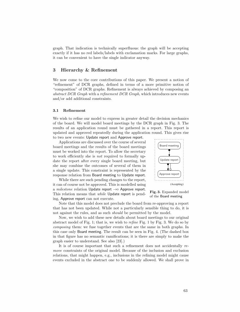
graph. That indication is technically superfluous: the graph will be acceptingexactly if it has no red labels/labels with exclamation marks. For large graphs,it can be convenient to have the single indicator anyway.
3 Hierarchy & Refinement
We now come to the core contributions of this paper. We present a notion of“refinement” of DCR graphs, defined in terms of a more primitive notion of“composition” of DCR graphs. Refinement is always achieved by composing anabstract DCR Graph with a refinement DCR Graph, which introduces new eventsand/or add additional constraints.
3.1 Refinement
We wish to refine our model to express in greater detail the decision mechanicsof the board. We will model board meetings by the DCR graph in Fig. 3. Theresults of an application round must be gathered in a report. This report isupdated and approved repeatedly during the application round. This gives riseto two new events: Update report and Approve report.
(Accepting)
Approve report
Board meeting
Update report
Fig. 3. Expanded modelof the Board meeting
Applications are discussed over the course of severalboard meetings and the results of the board meetingsmust be worked into the report. To allow the secretaryto work efficiently she is not required to formally up-date the report after every single board meeting, butshe may combine the outcomes of several of them ina single update. This constraint is represented by theresponse relation from Board meeting to Update report.
While there are such pending changes to the report,it can of course not be approved. This is modelled usinga milestone relation Update report →� Approve report.This relation means that while Update report is pend-ing, Approve report can not execute.
Note that this model does not preclude the board from re-approving a reportthat has not been updated. While not a particularly sensible thing to do, it isnot against the rules, and as such should be permitted by the model.
Now, we wish to add these new details about board meetings to our originalabstract model of Fig. 1; that is, we wish to refine Fig. 1 by Fig. 3. We do so bycomposing them: we fuse together events that are the same in both graphs. Inthis case only Board meeting. The result can be seen in Fig. 4. (The dashed boxin that figure has no semantic ramifications; it is there are simply to make thegraph easier to understand. See also [23].)
It is of course important that such a refinement does not accidentally re-move constraints of the original model. Because of the inclusion and exclusionrelations, that might happen, e.g., inclusions in the refining model might causeevents excluded in the abstract one to be suddenly allowed. We shall prove in
63

Theorem 4.10 that, roughly, when the two models agree on when fused eventsare included or excluded, the composition will not admit new behaviour; in thiscase we call it a refinement. In the present case, the only fused event is Boardmeeting, which has no inclusions or exclusions going into it in either model, sothis composition is really a refinement.
(Accepting)
Approve report
Board meeting
Update report
Application deadline
Receive application
%
Start round
Fig. 4. Refinement of Fig. 1 by Fig.3.
Refinement-as-composition in con-junction with DCR graphs havingno distinction between design-timeand run-time means that we canrefine a running model. Suppose,for instance, that we have deployedour initial abstract model of Fig. 1,and have reached state (5) in Fig. 2when it is decided that compli-ance with the board meeting re-port procedure of Fig. 3 must beenforced. We may add in these newconstraints by refining the runningmodel (Fig. 2, part 5) with the newconstraints (Fig. 3). Doing so yieldsthe new DCR graph seen in Fig. 5.Note how the pending state of thefused Board meeting event is pre-
served. And again, by virtue of the refinement Theorem 4.10, we can be assuredthat all constraints on execution of the original model is still preserved in thisnew refined one.
3.2 Subprocesses
Refinement gives us a disciplined method for extending models with new com-ponents; thus it gives us a hierarchical notion of process design. However, itdoes not fully capture the notion of sub-processes in traditional business mod-elling notations. Here, a sub-processes is a complex activity in the model thathas underlying behaviour which is instantiated when the sub-process is startedand closed when the sub-process ends. Such sub-processes can both be single-instance, meaning that only one instance of the sub-process will be active at anytime, or multi-instance, meaning that multiple instances of the sub-processes canexecute concurrently.
To enable modelling such sub-processes we extend DCR graphs to Hi-DCRgraphs. In these, we may associate with an event an entire other Hi-DCR graphwhich, when the event fires, is composed onto the current graph. We exemplifyHi-DCR Graphs by adding to our funding agency model a more detailed de-scription of the process for an individual application. As many applications maybe received and evaluated at the same time, we need a notion of sub-processes(and in particular multi-instance sub-processes) to fully capture this behaviour.
64
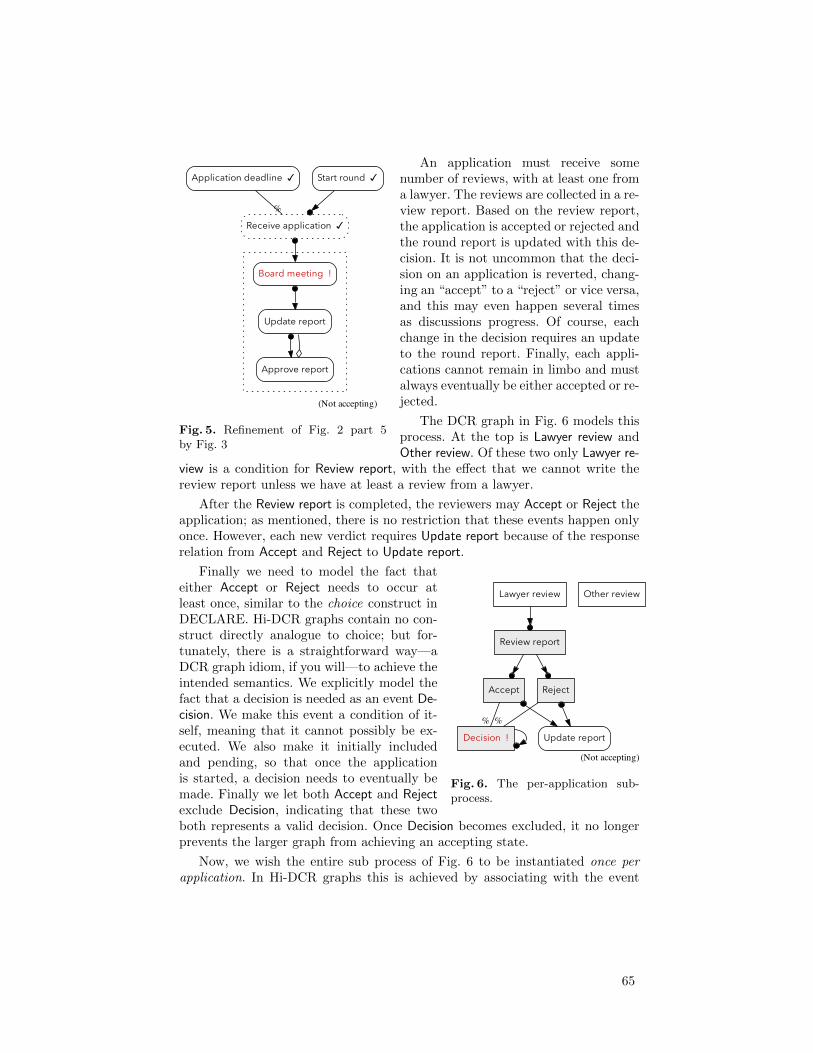
(Not accepting)
Approve report
Board meeting !
Update report
Application deadline ✓
Receive application ✓
%
Start round ✓
Fig. 5. Refinement of Fig. 2 part 5by Fig. 3
An application must receive somenumber of reviews, with at least one froma lawyer. The reviews are collected in a re-view report. Based on the review report,the application is accepted or rejected andthe round report is updated with this de-cision. It is not uncommon that the deci-sion on an application is reverted, chang-ing an “accept” to a “reject” or vice versa,and this may even happen several timesas discussions progress. Of course, eachchange in the decision requires an updateto the round report. Finally, each appli-cations cannot remain in limbo and mustalways eventually be either accepted or re-jected.
The DCR graph in Fig. 6 models thisprocess. At the top is Lawyer review andOther review. Of these two only Lawyer re-
view is a condition for Review report, with the effect that we cannot write thereview report unless we have at least a review from a lawyer.
After the Review report is completed, the reviewers may Accept or Reject theapplication; as mentioned, there is no restriction that these events happen onlyonce. However, each new verdict requires Update report because of the responserelation from Accept and Reject to Update report.
(Not accepting)
Accept
Decision !
%
Update report
Lawyer review
Review report
Other review
Reject
%
Fig. 6. The per-application sub-process.
Finally we need to model the fact thateither Accept or Reject needs to occur atleast once, similar to the choice construct inDECLARE. Hi-DCR graphs contain no con-struct directly analogue to choice; but for-tunately, there is a straightforward way—aDCR graph idiom, if you will—to achieve theintended semantics. We explicitly model thefact that a decision is needed as an event De-cision. We make this event a condition of it-self, meaning that it cannot possibly be ex-ecuted. We also make it initially includedand pending, so that once the applicationis started, a decision needs to eventually bemade. Finally we let both Accept and Rejectexclude Decision, indicating that these twoboth represents a valid decision. Once Decision becomes excluded, it no longerprevents the larger graph from achieving an accepting state.
Now, we wish the entire sub process of Fig. 6 to be instantiated once perapplication. In Hi-DCR graphs this is achieved by associating with the event
65
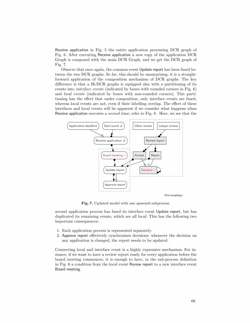
Receive application in Fig. 5 the entire application processing DCR graph ofFig. 6. After executing Receive application a new copy of the application DCRGraph is composed with the main DCR Graph, and we get the DCR graph ofFig. 7.
Observe that once again, the common event Update report has been fused be-tween the two DCR graphs. So far, this should be unsurprising: it is a straight-forward application of the composition mechanism of DCR graphs. The keydifference is that a Hi-DCR graphs is equipped also with a partitioning of itsevents into interface events (indicated by boxes with rounded corners in Fig. 6)and local events (indicated by boxes with non-rounded corners). This parti-tioning has the effect that under composition, only interface events are fused,whereas local events are not, even if their labelling overlap. The effect of theseinterfaces and local events will be apparent if we consider what happens whenReceive application executes a second time; refer to Fig. 8. Here, we see that the
(Not accepting)
Accept
Decision !
%
Update report
Lawyer review
Review report
Other review
Reject
%
Approve report
Board meeting !
Application deadline
Receive application ✓
%
Start round ✓
Fig. 7. Updated model with one spawned subprocess.
second application process has fused its interface event Update report, but hasduplicated its remaining events, which are all local. This has the following twoimportant consequences:
1. Each application process is represented separately.2. Approve report effectively synchronises decisions: whenever the decision on
any application is changed, the report needs to be updated.
Connecting local and interface event is a highly expressive mechanism. For in-stance, if we want to have a review report ready for every application before theboard meeting commences, it is enough to have, in the sub-process definitionin Fig. 6 a condition from the local event Review report to a new interface eventBoard meeting.
66

(Not accepting)
Accept
Decision !
%
Update report
Lawyer review
Review report
Other review
Reject
%
Accept
Decision !
%
Lawyer review
Review report
Other review
Reject
%
Approve report
Board meeting !
Application deadline
Receive application ✓
%
Start round ✓
Fig. 8. After spawning a second subprocess in Fig. 7.
4 Foundations
In this section, we review the formal theory of DCR graphs, then formally in-troduce their refinement and their generalisation to Hi-DCR graphs.
We distinguish between events and labels. In a single workflow, the samelabel may occur multiple times. For instance, the label “Review report” occurstwice in Fig. 8. We accommodate such multiplicity by considering events (theboxes), as distinct from their label (the text in the boxes). When the distinctionbetween events and labels does not matter, we use the words interchangeably.For instance, in Fig. 1 and 3 we speak of “the event Board meeting”, since thelabel Board meeting uniquely identifies an event. To simplify the presentation wewill let the labelling of events remain implicit in the formal definitions.
Definition 4.1 (DCR Graph [8]). A DCR graph is a tuple (E,R,M) where
– E is a finite set of (labelled) events, the nodes of the graph.– R is the edges of the graph. Edges are partioned into five kinds, named and
drawn as follows: The conditions (→•), responses (•→), milestones (→�),inclusions (→+), and exclusions (→%).
– M is the marking of the graph. This is a triple (Ex,Re, In) of sets of events,respectively the previously executed (Ex), the currently pending (Re), and thecurrently included (In) events.
When G is a DCR graph, we write, e.g., E(G) for the set of events of G, as wellas, e.g., Ex(G) for the executed events in the marking of G.
Notation. For a binary relation → ⊆ X × Y we write “→ Z” for the set{x ∈ X | ∃z ∈ Z. x → z}, and similarly for “Z→”. For singletons we usuallyomit the curly braces, writing →e rather than →{e}.
67

With the definition of DCR graphs and notation in place, we define thedynamic semantics of a DCR graph. First, the notion of an event being enabled,ready to execute.
Definition 4.2 (Enabled events). Let G = (E,R,M) be a DCR graph, withmarking M = (Ex,Re, In). We say that an event e ∈ E is enabled and writee ∈ enabled(G) iff (a) e ∈ In, (b) In ∩ (→•e) ⊆ Ex, and (c) In ∩ (→�e) ⊆ E\Re.That is, enabled events (a) are included, (b) their included conditions alreadyexecuted, and (c) have no included milestones with an unfulfilled responses.
Definition 4.3 (Execution). Let G = (E,R,M) be a DCR graph with markingM = (Ex,Re, In). Suppose e ∈ enabled(G). We may execute e obtaining theresulting DCR graph (E,R,M′) with M′ = (Ex′,Re′, In′) defined as follows.
1. Ex′ = Ex ∪ e2. Re′ = (Re \ e) ∪ (e•→)3. In′ = (In \ (e→%)) ∪ (e→+)
That is, to execute an event e one must: (1) add e to the set Ex of executedevents. (2) Update the currently required responses Re by first removing e, thenadding any responses required by e. (3) Update the currently included events byfirst removing all those excluded by e, then adding all those included by e.
Definition 4.4 (Transitions, runs, traces). Let G be a DCR graph. If e ∈enabled(G) and executing e in G yields H, we say that G has transition on e toH and write G −→e H. A run of G is a (finite or infinite) sequence of DCRgraphs Gi and events ei such that: G = G0 −→e0 G1 −→e1 . . .A trace of G is a sequence of labels of events ei associated with a run of G. Wewrite runs(G) and traces(G) for the set of runs and traces of G, respectively
Not every run or trace represents an acceptable execution of the graph: We needalso that every response requested is eventually fulfilled or excluded.
Definition 4.5 (Acceptance). A run G0 −→e0 G1 −→e1 . . . is accepting ifffor all n with e ∈ In(Gn) ∩ Re(Gn) there exists m ≥ n s.t. either em = e, ore 6∈ In(Gm). A trace is accepting iff it has an underlying run which is.
Acceptance tells us which workflows a DCR graph accepts, its language.
Definition 4.6 (Language). The language of a DCR graph G is the set of itsaccepting traces. We write lang(G) for the language of G.
We now know enough to formalise the first DCR graph we saw.
Example 4.7. The DCR graph of Fig. 1 and 2 has events a, s, r, b labelled Ap-plication deadline (a), Start round (s), Receive application (r), and Board meet-ing (b). It has relation R given by →%= {(a, r)}, →+= ∅, →•= {s, r}, •→={r, b} and →�= ∅. We can find a run of this DCR graph in Fig. 2: B1 −→s
B2 −→r B3 −→r B4 −→a B5 −→b B6
Here, B1, B2 are accepting, whereas B3–B5 have b pending and so are not.
68
4.1 Composition & interfaces
Composition of DCR graphs was originally introduced in [10].
Definition 4.8 (Composition of DCR graphs). The composition G | H ofDCR graphs G and H is defined by taking the union of all components.Formally: G | H = (E ∪ E′,R ∪ R′, (Ex ∪ Ex′,Re ∪ Re′, In ∪ In′))The empty or zero DCR graph, 0, is the unique DCR graph with no events.
Composition does not in itself give “refinement” in the classical sense: inDCR graphs, even if G,H share events and labels, the language of G | H mightactually be larger than either G or H. The following definition helps narrowdown what are “good” compositions.
Notation. The projection of a sequence σ to a set E is obtained by removingevery element of σ not in E. For instance, the projection of σ = AABCABC toE = {A,C} is σ|E = AACAC. We lift projection to sets of sequences pointwise.
Definition 4.9 (Refinement). H refines G iff(lang(G | H)
)|E(G) ⊆ lang(G).
To help establish refinements, we have the following theorem, which statesthat a DCR graph G is refined by a DCR-graph H if they have no shared eventwhich may be included or excluded unilaterally by H.
Theorem 4.10. H refines G if in H shared labels are associated only withshared events, and for all f ∈ E(G) ∩ E(H) and e ∈ E(H) we have that:
1. If e→%H f then also e→%G f, 3. Ex(H) ∩ E(G) ⊆ Ex(G),
2. if e→+H f then also e→+G f, 4. In(H) ∩ E(G) ⊆ In(G).
Conditions (1) and (2) mean that H cannot unilaterally include or excludeshared events; conditions (3) and (4) that the marking of H does not change theinclusion- or execution-state of shared events.
Example 4.11. As an example, taking G to be the DCR graphs of Fig. 1 and Hto be the one of Fig. 3, then both G,H fulfil the criteria of Theorem 4.10. Thus,we can be sure that when we compose them to obtain G | H in Fig. 4, theirlocal behaviour is preserved: the valid execution orders of Application deadline,Start round, Receive application, and Board meeting in Fig. 4 are all also validaccording to Fig. 1.
4.2 Hi-DCR graphs
Towards DCR-graphs with sub-processes, we need first DCR graphs with inter-faces, i-DCR graphs.
Definition 4.12 (i-DCR graph). An i-DCR graph is a tuple G = (E,R,M, I)such that (E,R,M) is a DCR graph and I ⊆ E. Events L = E \ I are local events.An i-DCR graph inherits notions of enabled events, execution, and zero from itsunderlying DCR-graph.
69
We note that once we can speak of execution, we have using Definitions 4.4, 4.5,and 4.6 also definitions of transistions, runs, traces, acceptance, and language.
The point of the interface I is to allow us to choose which events should fusewith similar events in composition, and which should be considered private. Toavoid fusing of private events, we must sometimes employ renamings.
Definition 4.13 (Freshness, compatibility). If G,H are i-DCR graphs wesay an that G is fresh for H iff L(G)∩E(H) = ∅. We say that they are compatibleiff they are both fresh for the other. We say that G,H are equivalent if they arestructurally identical up to the choice of local events.
The composition of i-DCR graphs guarantees that local events of compatiblegraphs do not overlap.
Definition 4.14 (i-DCR composition). The composition G | H of i-DCRgraphs G,H is defined as for DCR graphs, taking interfaces of the combinedgraph to be I(G) \ L(H) ∪ I(H) \ L(G).
For compatible i-DCR graphs, this definition is equivalent to taking simply I∪ I′.
Definition 4.15 (Hi-DCR). A Hi-DCR graph is a tuple G = (E,R,M, I,S)where S is a map taking events to Hi-DCR graphs and (E,R,M, I) is the under-lying i-DCR graph G|ι of G. An event e of G is enabled in G iff it is in G|ι.
Note that if one wants an event e to not spawn any sub-process, one simplymaps it to sub-process definition to zero, i.e., takes S(e) = 0.
Definition 4.16 (Hi-DCR execution). Suppose e is an event of the Hi-DCRgraph G, that e ∈ enabled(G) and that S(e) = H. Then to execute e in G:
1. Pick some H ′ equivalent to H but fresh for G.2. Execute e in G | H ′ (considered a DCR graph) to obtain H.
That is, if G | H ′ = (E,R,M, I,S), we execute e in (E,R,M) obtaining (E,R,M′),then declare the execution of e in G | H ′ to be (E,R,M′, I,S).
Example 4.17. The notion of i-DCR graph and the definition of Hi-DCR graphexecution explains formally why the event Approve decisions is not duplicatedwhen a subprocess is spawned between Fig. 7 and 8: it is an interface event, andso is fused in the composition that happens when new sub-processes are spawned.The event Review report in the sub-process, on the other hand, is duplicated: Itis local, and because execution of Hi-DCR graphs choose fresh names for localevents during spawning, it is duplicated.
Theorem 4.18. Hi-DCR graphs are strictly more expressive then DCR Graphsand therefore also strictly more expressive then ω-regular languages.
Proof. Hi-DCR graphs conservatively extend DCR graphs, which are known toexpress exactly ω-regular languages [14]. But in Fig. 8, every time we executeReceive application we are will execute at least one Accept or Reject. This requirescounting Receive application which is impossible for ω-regular languages.
70

5 Implementation
For experimentation, we have implemented a prototype tool for working withHi-DCR graphs. This tool features a simulation engine capable of executingtransitions, and of dynamic re-configuration using both unconstrained composi-tion (Definition 4.8) and refinement (Definition 4.9). For finite-state graphs, thetool can do also basic model-checking tasks, such as finding a path to dead-lock,termination, acceptance, or some event being enabled. Whereas in the other sec-tions of this paper, we represented DCR graphs graphically, as figures producedby the tool, the tool inputs a textual representation. As an example of that rep-resentation, consider again Fig. 6. Its equivalent textual representation is below.
"Other review" 1
"Lawyer review" 2
-->* "Review report" 3
-->* ("Accept" "Reject") 4
-->% !"Decision" 5
"Decision" -->* "Decision" 6
("Accept" "Reject") -->% "Decision" 7
("Accept" "Reject") 8
*--> "Update report" 9
10
/("Other review" "Lawyer review" 11
"Review report" 12
"Accept" "Reject" "Decision") 13
All events are interface events bydefault; local events are specifiedby prefixing them with a slash‘/’ (line 11-13). Events can alsobe prefixed ‘+’, ‘%’, and ‘!’, (line5) indicating that they are ini-tially included, excluded, respec-tively pending. For convenience,the language allows both chainingof events and relations (line 2–5)as well as relating multiple things(line 7).
The tool uses Graphviz [5] toautomatically produce diagrams.The diagrams in the present paper were all so generated. The tool is imple-mented in F# and runs on the major platforms. The executable and source codecan be found at [4].
6 Conclusion
In this paper we first demonstrated how DCR Graphs can be used for incremen-tal, declarative design of processes, by introducing a notion of compositional re-finement that guarantees language inclusion (with respect to the labels of eventspresent in the original process) and thus preserves compliance for acceptingexecutions. We then used these techniques to introduce Hi-DCR Graphs, a con-servative extension of DCR graphs, which allows events to spawn sub-processes.The extensions have been presented and motivated using as an example an ab-straction of a real-world case supplied by our industry partner, ExformaticsA/S. We provided a formal semantics for Hi-DCR Graphs and demonstratedby example that they are more expressive then ω-regular languages. Finally wereported on a prototype implementation of Hi-DCR Graphs which supports aprogramming-like syntax, automatic visualisation, simulation, and rudimentarymodel-checking.
71
6.1 Future Work
While the notion of refinement introduced in the present paper preserves com-pliance for accepting executions, it may in fact introduce errors such as livelocksand deadlocks. The simplest example would be to refine a process with a DCRgraph containing a single, included (local) event having itself as condition andbeing initiatlly required as response. In [15] it is shown how adaptations canbe verified for safety and liveness, by relying on the map from DCR Graphsto Buchi-automata [16], which is further mapped to Promela and verified in theSPIN model-checker. However, as demonstrated in [15], this approach is not veryefficient. We are therefore currently investigating techniques for more efficientverification of DCR Graphs in the presense of adaptations.
As was mentioned in the related work section the development of Hi-DCRGraphs brings us closer to the GSM notation, and we plan to use this work in thefuture as a basis for formal mappings between GSM and DCR Graphs models.
The question of the precise expressive power of Hi-DCR graph remains open.We conjecture that they are Turing-equivalent. This points to another relevantquestion, namely how to constrain Hi-DCR graphs to allow safety and livenessguarantees. An obvious possible constraint would be to bound the number timeseach sub-process can be spawned by a constant. Because of the formalization ofspawning based on composition, it follows that this constrains the model to theexpressiveness of standard DCR Graphs, that is, to Buchi-automata.
Formal expressive power aside, in practice many idiomatic constructs, likethe “disjunctive responses” used in Fig. 8 could be formalised as derived con-structs in their own right, potentially making them more accessible to end-users,much like DECLARE is formalised in terms of LTL. Similarly, other questionsregarding the usability of the approach will be investigated in future studiesthrough empirical investigations undertaken in cooperation with our industrialpartners and end-users.
Acknowledgments. We gratefully acknowledge fruitful discussions with Rik Es-huis. The work is supported by grant VELUX 33295, 2014-2017 and the DanishAgency for Science, Technology and Innovation.
References
1. van der Aalst, W., Pesic, M., Schonenberg, H., Westergaard, M., Maggi, F.M.:Declare. Webpage (2010), http://www.win.tue.nl/declare/
2. van der Aalst, W.M., Pesic, M.: DecSerFlow: Towards a truly declarative serviceflow language. In: WS-FM 2006. LNCS, vol. 4184, pp. 1–23. Springer (2006)
3. Carbone, M., Hildebrandt, T.T., Perrone, G., Wasowski, A.: Refinement for tran-sition systems with responses. In: FIT. EPTCS, vol. 87, pp. 48–55 (2012)
4. Debois, S.: DCR exploration tool v.6. IT University of Copenhagen (2014), http://www.itu.dk/research/models/wiki/index.php/DCR_Exploration_Tool
5. Ellson, J., Gansner, E., Koutsofios, L., North, S., Woodhull, G.: Graphviz— opensource graph drawing tools. In: Graph Drawing, LNCS, vol. 2265, pp. 483–484.Springer (2002), http://dx.doi.org/10.1007/3-540-45848-4_57
72

6. Groefsema, H., Bucur, D.: A survey of formal business process verification: Fromsoundness to variability. In: Proceedings of the Third International Symposium onBusiness Modeling and Software Design. p. 198–203 (2013), http://www.cs.rug.nl/ds/uploads/pubs/groefsema-bmsd.pdf
7. Hildebrandt, T.T., Marquard, M., Mukkamala, R.R., Slaats, T.: Dynamic conditionresponse graphs for trustworthy adaptive case management. In: OTM Workshops.LNCS, vol. 8186, pp. 166–171. Springer (2013)
8. Hildebrandt, T.T., Mukkamala, R.R.: Declarative event-based workflow as dis-tributed dynamic condition response graphs. In: PLACES. EPTCS, vol. 69, pp.59–73 (2010)
9. Hildebrandt, T.T., Mukkamala, R.R., Slaats, T.: Nested dynamic condition re-sponse graphs. In: FSEN. LNCS, vol. 7141, pp. 343–350. Springer (2011)
10. Hildebrandt, T.T., Mukkamala, R.R., Slaats, T.: Safe distribution of declarativeprocesses. In: SEFM. LNCS, vol. 7041, pp. 237–252. Springer (2011)
11. Hull, R., Damaggio, E., Fournier, F., Gupta, M., Heath, F.T., Hobson, S., Line-han, M.H., Maradugu, S., Nigam, A., Sukaviriya, P., Vaculın, R.: Introducing theguard-stage-milestone approach for specifying business entity lifecycles. In: WS-FM. LNCS, vol. 6551, pp. 1–24. Springer (2010)
12. Maggi, F.M., Westergaard, M., Montali, M., van der Aalst, W.M.P.: Runtime ver-ification of ltl-based declarative process models. In: Khurshid, S., Sen, K. (eds.)RV. Lecture Notes in Computer Science, vol. 7186, pp. 131–146. Springer (2011)
13. Montali, M.: Specification and Verification of Declarative Open Interaction Models- A Logic-Based Approach, Lecture Notes in Business Information Processing,vol. 56. Springer (2010)
14. Mukkamala, R.R.: A Formal Model For Declarative Workflows: Dynamic ConditionResponse Graphs. Ph.D. thesis, IT University of Copenhagen (June 2012)
15. Mukkamala, R.R., Hildebrandt, T., Slaats, T.: Towards trustworthy adaptive casemanagement with dynamic condition response graphs. In: EDOC. pp. 127–136.IEEE (2013)
16. Mukkamala, R.R., Hildebrandt, T.T.: From dynamic condition response structuresto buchi automata. In: TASE. pp. 187–190. IEEE Computer Society (2010)
17. Mukkamala, R.R., Hildebrandt, T.T., Tøth, J.B.: The resultmaker online consul-tant: From declarative workflow management in practice to ltl. In: EDOCW. pp.135–142. IEEE Computer Society (2008)
18. Object Management Group BPMN Technical Committee: Business Process Modeland Notation, version 2.0, http://www.omg.org/spec/BPMN/2.0/PDF
19. Reijers, H., Mendling, J., Dijkman, R.: On the usefulness of subprocesses in busi-ness process models. BPM Reports 1003, Eindhoven (2010)
20. Slaats, T., Mukkamala, R.R., Hildebrandt, T.T., Marquard, M.: Exformaticsdeclarative case management workflows as DCR graphs. In: BPM. LNCS, vol.8094, pp. 339–354. Springer (2013)
21. Vardi, M.Y.: An automata-theoretic approach to linear temporal logic. In: Moller,F., Birtwistle, G.M. (eds.) Banff Higher Order Workshop. Lecture Notes in Com-puter Science, vol. 1043, pp. 238–266. Springer (1995)
22. Winskel, G.: Event structures. In: Brauer, W., Reisig, W., Rozenberg, G. (eds.)Advances in Petri Nets. LNCS, vol. 255, pp. 325–392. Springer (1986)
23. Zugal, S., Soffer, P., Pinggera, J., Weber, B.: Expressiveness and understandabil-ity considerations of hierarchy in declarative business process models. In: BM-MDS/EMMSAD. Lecture Notes in Business Information Processing, vol. 113, pp.167–181. Springer (2012)
73

A Case for Declarative Process Modelling:Agile Development of a Grant Application System
Søren Debois, Thomas Hildebrandt andTijs Slaats
IT University of CopenhagenRued Langgaardsvej 7
2300 Copenhagen, DenmarkEmail: {debois,hilde,tslaats}@itu.dk
Morten Marquard andTijs Slaats
Exformatics A/SCopenhagen, Denmarkwww.exformatics.com
Email: {mmq,ts}@exformatics.com
Abstract—We report on a recent industrial project carried outby Exformatics A/S in which the company used the declarativeDCR Graphs notation to model and implement the grant appli-cation process of a Danish foundation. We present the processand discuss the advantages of the approach and challenges facedboth while modelling and implementing the process. Finally, wediscuss current work on extensions to the DCR Graphs notationaiming to address the challenges raised by the case study and tosupport the declarative, agile approach.
I. INTRODUCTION
In the private as well as public sector, front-end customerservices and their corresponding back-end processes and work-flows are increasingly being digitalised by so-called ProcessAware Information Systems (PAIS) [1]. The technology ispushed forward by promises of more usable, efficient and agilebusiness processes, ensured to be compliant with business rulesand the law.
Traditionally, functionality and user-experience of softwaresystems have been described in a requirement specificationbefore implementation. The requirements for functionalitymay be supported by semi-formal models such as e.g. UMLsequence and activity diagrams and requirements for user-experience may be supported by use cases, user-interfacedescriptions and scenarios.
The new generation of PAIS are based on explicit, graphicaland executable process models such BPMN [2], which sup-ports a more agile development process, in which developersjointly with domain-experts during implementation, can designand simulate business processes and evaluate user-experiences.
However, the need for changes and adaptation to a PAISdoes not end, when the system is being delivered to thecustomer. It is more the rule than the exception that theprocesses need to be adapted after the system has been put intouse, either because the requirements where wrong or the needschanged before the final delivery. Indeed, often adaptations dueto changes in business processes will be needed repeatedlythroughout the entire lifetime of the system.
Moreover, it has been recognised in research, that imper-ative process descriptions such as BPMN that are based onexplicit process flows tend to capture processes too rigidly,introducing un-justified dependencies and order between ac-
tivities [1], [3], thereby increasing the need for adaptations toprocesses, even during execution of a process.
An explanation for this is, that the explicit flow graphsdescribe how a process is to be carried out, not why. Byanalogy to a way-finding service, it corresponds to describing asingle route through a city, perhaps remembering to take a fewpossible exceptions into account. However, if the goal or maplater changes, or the route is questioned regarding a potentialimprovement the flow-graph does not contain the informationneeded to derive a new route.
As an alternative, declarative process descriptions havebeen proposed by several research groups [3], [4], [5], [6],[7] as a way to achieve more flexible PAIS, by having processmodels that capture the why and not the how. The declarativeapproach has not seen wide-spread industrial adaptation yetand tool support has generally been limited to academicprototypes, which had led to the question if practitioners seeactual opportunities to use declarative techniques. This has ledto a study investigating what process modelling practitionersthink of declarative modelling [8], which showed that theaudience was receptive to the underlying concepts of thedeclarative modelling paradigm and the Declare [3], [4] andDCR Graphs notations, but also discovered that they hadsome difficulty getting used to the new paradigm and that thegraphical notations used by the current notations were foundto not always be intuitive, which made them relatively difficultto work with.
Exformatics A/S have during the past three years jointlywith researchers at IT University of Copenhagen been devel-oping, applying and implementing the declarative DCR graphsmodel [5], [6] in their standard Adaptive Case Mangementsystem. A key feature of DCR graphs is that they do not relyon a transformation before execution: The graphs describe boththe initial state and the intermediate states, and thus supportprocess adaptation during execution.
In the present paper we report on a recent industrialproject in which Exformatics used the declarative DCR Graphsnotation to model and implement the grant application processof a Danish foundation, the Dreyer foundation.
In Sec. II we first present the background for introducing aPAIS at the Dreyer foundation, and then in Sec. III we describethe key process(es) to be supported. In Sec. IV we first give the
74
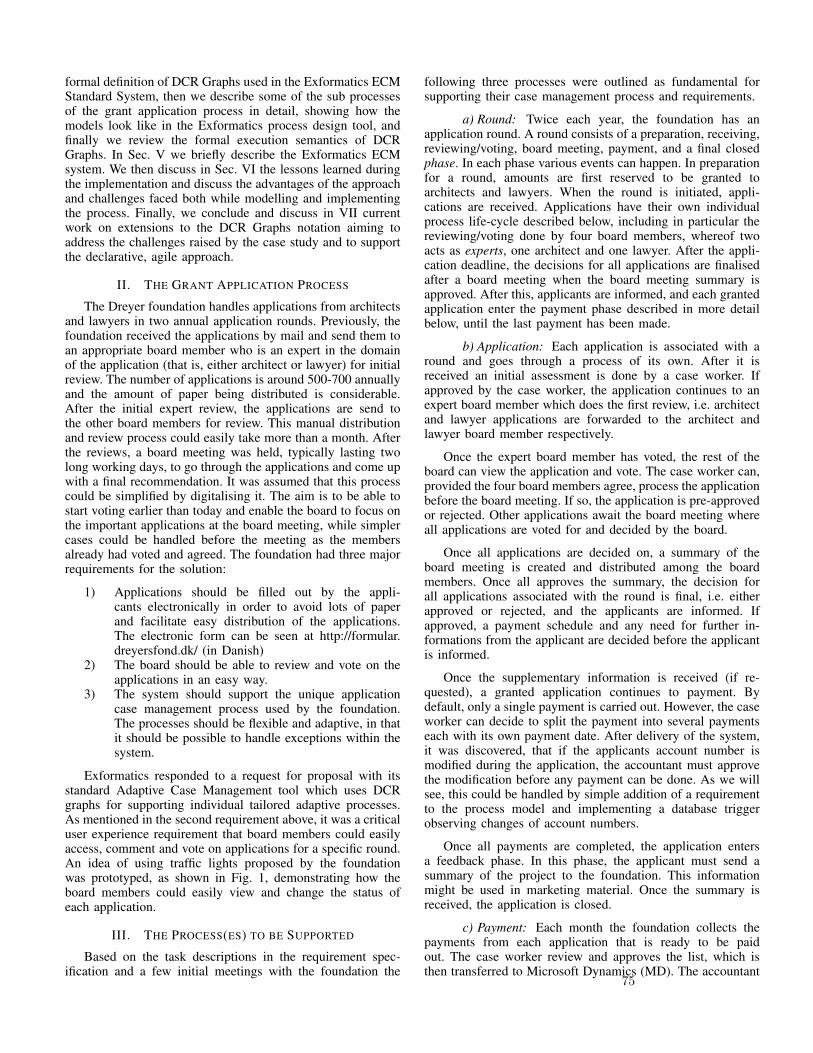
formal definition of DCR Graphs used in the Exformatics ECMStandard System, then we describe some of the sub processesof the grant application process in detail, showing how themodels look like in the Exformatics process design tool, andfinally we review the formal execution semantics of DCRGraphs. In Sec. V we briefly describe the Exformatics ECMsystem. We then discuss in Sec. VI the lessons learned duringthe implementation and discuss the advantages of the approachand challenges faced both while modelling and implementingthe process. Finally, we conclude and discuss in VII currentwork on extensions to the DCR Graphs notation aiming toaddress the challenges raised by the case study and to supportthe declarative, agile approach.
II. THE GRANT APPLICATION PROCESS
The Dreyer foundation handles applications from architectsand lawyers in two annual application rounds. Previously, thefoundation received the applications by mail and send them toan appropriate board member who is an expert in the domainof the application (that is, either architect or lawyer) for initialreview. The number of applications is around 500-700 annuallyand the amount of paper being distributed is considerable.After the initial expert review, the applications are send tothe other board members for review. This manual distributionand review process could easily take more than a month. Afterthe reviews, a board meeting was held, typically lasting twolong working days, to go through the applications and come upwith a final recommendation. It was assumed that this processcould be simplified by digitalising it. The aim is to be able tostart voting earlier than today and enable the board to focus onthe important applications at the board meeting, while simplercases could be handled before the meeting as the membersalready had voted and agreed. The foundation had three majorrequirements for the solution:
1) Applications should be filled out by the appli-cants electronically in order to avoid lots of paperand facilitate easy distribution of the applications.The electronic form can be seen at http://formular.dreyersfond.dk/ (in Danish)
2) The board should be able to review and vote on theapplications in an easy way.
3) The system should support the unique applicationcase management process used by the foundation.The processes should be flexible and adaptive, in thatit should be possible to handle exceptions within thesystem.
Exformatics responded to a request for proposal with itsstandard Adaptive Case Management tool which uses DCRgraphs for supporting individual tailored adaptive processes.As mentioned in the second requirement above, it was a criticaluser experience requirement that board members could easilyaccess, comment and vote on applications for a specific round.An idea of using traffic lights proposed by the foundationwas prototyped, as shown in Fig. 1, demonstrating how theboard members could easily view and change the status ofeach application.
III. THE PROCESS(ES) TO BE SUPPORTED
Based on the task descriptions in the requirement spec-ification and a few initial meetings with the foundation the
following three processes were outlined as fundamental forsupporting their case management process and requirements.
a) Round: Twice each year, the foundation has anapplication round. A round consists of a preparation, receiving,reviewing/voting, board meeting, payment, and a final closedphase. In each phase various events can happen. In preparationfor a round, amounts are first reserved to be granted toarchitects and lawyers. When the round is initiated, appli-cations are received. Applications have their own individualprocess life-cycle described below, including in particular thereviewing/voting done by four board members, whereof twoacts as experts, one architect and one lawyer. After the appli-cation deadline, the decisions for all applications are finalisedafter a board meeting when the board meeting summary isapproved. After this, applicants are informed, and each grantedapplication enter the payment phase described in more detailbelow, until the last payment has been made.
b) Application: Each application is associated with around and goes through a process of its own. After it isreceived an initial assessment is done by a case worker. Ifapproved by the case worker, the application continues to anexpert board member which does the first review, i.e. architectand lawyer applications are forwarded to the architect andlawyer board member respectively.
Once the expert board member has voted, the rest of theboard can view the application and vote. The case worker can,provided the four board members agree, process the applicationbefore the board meeting. If so, the application is pre-approvedor rejected. Other applications await the board meeting whereall applications are voted for and decided by the board.
Once all applications are decided on, a summary of theboard meeting is created and distributed among the boardmembers. Once all approves the summary, the decision forall applications associated with the round is final, i.e. eitherapproved or rejected, and the applicants are informed. Ifapproved, a payment schedule and any need for further in-formations from the applicant are decided before the applicantis informed.
Once the supplementary information is received (if re-quested), a granted application continues to payment. Bydefault, only a single payment is carried out. However, the caseworker can decide to split the payment into several paymentseach with its own payment date. After delivery of the system,it was discovered, that if the applicants account number ismodified during the application, the accountant must approvethe modification before any payment can be done. As we willsee, this could be handled by simple addition of a requirementto the process model and implementing a database triggerobserving changes of account numbers.
Once all payments are completed, the application entersa feedback phase. In this phase, the applicant must send asummary of the project to the foundation. This informationmight be used in marketing material. Once the summary isreceived, the application is closed.
c) Payment: Each month the foundation collects thepayments from each application that is ready to be paidout. The case worker review and approves the list, which isthen transferred to Microsoft Dynamics (MD). The accountant
75

is then asked to post the list and prepare and approve thepayouts. After the accountant has done her work, the caseworker is asked to approve the payouts. Once done the payoutsare automatically transferred to the applicant through theintegrated banking solution. Further, the case worker retrievestax information about the applicants which is uploaded to theDanish tax authorities. Once all steps are done all paymentsare marked as completed. Any errors during the payout, e.g.invalid account numbers, are handled simply by manuallyremoving the payment event from MD and modifying theaccount number.
IV. THE DCR GRAPH PROCESS MODEL
In this section, we first recall DCR graphs introducedin [5], [6] and further developed (e.g. by adding data) andimplemented in the Exformatics ECM [9], [10], [11]. Wethen show how some of the sub processes in the Dreyer casemanagement process described above where modelled as DCRGraphs.
Definition 1 (DCR Graph and DCR Graph with Data):A DCR Graph is a tuple (E, l,R,M) where
• E is a finite set of events (the nodes of the graph).
• l is a labelling function, assigning a label to each event
• R is a finite set of relations between events (the edgesof the graph). The relations are partioned into fivekinds, the conditions (→•), responses (•→), mile-stones (→�), inclusions (→+), and exclusions (→%).
• M is the marking of the graph. A marking representthe state of the process and is a triple (Ex,Re, In)of sets of events, respectively the executed (Ex), thepending (Re), and the included (In) events.
A DCR Graph with data is a tuple (E, l,R,Md, g,V) where Vis a set of data variables, Md = (M, ev), (E, l,R,M) is a DCRGraph, ev is an evaluation function mapping data variables to
values, and g is a (partial) relation guard mapping from (someof) the relations to boolean expressions over variables.
Events are atomic and may represent the beginning or end ofan activity, e.g. ”start application round” or ”review done”.An event may also represent a decision being made (e.g.”vote reject”) or indeed an atomic event, e.g. account numberchanged. In the ECM implementation, data variables of DCRGraphs with data are mapped to entries in the case database,and events can be triggered from the case management user-interface, by the system itself or by triggers set up in thedatabase. The database may be changed by events externallyto the model. This provides a very flexible implementation,but also somewhat limits what can be verified formally.
Before giving the formal semantics, we will give someexample models of parts of the Dreyer process.
A. The review sub-process
As the name suggests, DCR graphs are graphs. They arerepresented visually in the DCRGraph editor [12] as in Fig. 2illustrating the review sub process for an application.
Events (boxes) with labels (the text inside them) are related toother events by various arrows. If two events have the samelabel, the event ID is shown in italics in the bottom right corner.Otherwise, the editor chooses by default the event ID to be thesame as the label and then it is not shown. In review processthere are only four events, representing the four (submissionof) review events by the four board members. The labels areLawyer Review, Architect Review, Review, and Review.Note also that each box has an ”ear” with the role assignment.
Relations between the events govern their relative order ofoccurrence. When not constrained by any relations, events canhappen in any order and any number of times. The reviewsub process only uses guarded condition relations. The guardexpressions are referring to the variable R which indicates if
Fig. 1. Board overview: Clicking on the round circles, grey, yellow, red or green, the board members can cast their vote and give a public and private comment.76

Fig. 2. A DCR graph for the review sub-process
this is an application for Lawyer projects (R = 1) or Architectprojects (R = 2). The meaning of the guarded relation is thatit is only present if the guard is true. The figure shows thestate if R = 2, and the ”stop signs” indicate that LawyerReview, Review, and Review are disabled because the guardon the condition from Lawyer Review, evaluates to true, whileArchitect Review is enabled because its constraint on the con-dition relation from Architect Review evaluates to false. Thenotation and semantics of the (unguarded) condition relationis similar to the precedence constraint in DECLARE [3], [4].
A key advantage of DCR graphs is that the graph directlyrepresents the state of execution. There is no distinction be-tween design-time and run-time. After executing the Architectreview event, all events are possible. (Also Architect review,thereby allowing a new review to be submitted). The markingis visualised in the editor and simulation tool by adding acheck mark to the Architect Review event indicating that ithas been executed, as shown in Fig. 3.
B. The payment sub-process
A more complex example illustrating the use of all fivekinds of relations is provided by the payment sub process inFig. 7.
Changes of account numbers happen outside the casemanagement system, but account numbers are registered inthe database. By implementing a trigger that monitors accountnumbers in the database, any change can execute an eventAccount number changed in the case management process.Once this event is executed, the approve account numberis made a required response by the (blue) response relation
Fig. 3. A DCR graph for the review sub-process after the architect review
Fig. 4. A DCR graph for the payment sub-process
77

Fig. 5. A DCR graph for the payment sub-process after change of accountnumber.
with a bullet at the tail. In the marking, this is recorded byadding Approve Account Number to the set Re of pendingresponses. In the editor, it is visualised graphically by adding a(red) exclamation mark to the event, as shown in Fig. 5. As theapprove account number event is a milestone, indicated bythe (purple) relation with diamond at the head, for the paymentphase, any payment event will be blocked until the approveaccount number has been executed, e.g. completed by theaccountant.
The event First payment has role DBAutomatic, whichmeans that it is carried out by the system and not a use(technically, it is scheduled for a date). Once it is executedit excludes itself, since it is related by the (red) exclusionrelation with a % at the end to itself. This in turns enablesa new event Undo payment allowing the case worker to undoa payment. If the Undo payment is executed, it includesthe payment again, due to the (green) inclusion relation witha + at the end, and makes it a required response, becauseof the (blue) response relation. Note that once the paymenthas been registered as completed (notified by the Paymentcomplete database trigger, Undo payment is excluded andthus the payment can no longer be undone. The idea of thisprocesses is, that if an error occurred in the payment (i.e. it isnot completed) the error can be fixed by manually executingthe Undo paymentevent, but once the payments is send tothe bank without any errors the caseworker cannot redo thepayment anymore by marking the payment as having an error.
C. Dynamic addition of sub processes
If the case worker adds one more payment to the applica-tion, the graph is dynamically modified resulting in the graph
Fig. 6. A DCR graph for the payment sub-process with two payouts
shown in Fig. IV-C
Notice that adding a payment result in three new events, apattern of events, which has the same structure as the initialpayment event. The pattern is added dynamically to the DCRgraph modifying the logic. Notice also that Approve accountnumber is a milestone for all the nested events in the Payoutphase. Doing so simplifies the logic as any change to accountnumber will block any payment event.
D. Cross-process synchronization
In the example of payment sub-processes above, dynamicaddition of processes was handled by directly modifyingthe graph at runtime, and there were no relations connecteddirectly to the payment sub-processes.
We can also add sub processes by starting new instances ofprocesses, and synchronise execution through database triggers(i.e. events with role DBtrigger) and auto-execution events (i.e.events with role DBautomatic).
Such synchronization exists allowing applications to bepre-approved before handled formally at the board meeting, ifthe board cast 4 equal votes, or the board simply informs thecase worker to pre-approve the application and start payment.At a certain point, such pre-approval cannot happen anymore,but must await board meeting summary approval, i.e. approvalfrom all four board members that the meeting summary hasbeen approved. The round therefore has an event Block Further
78
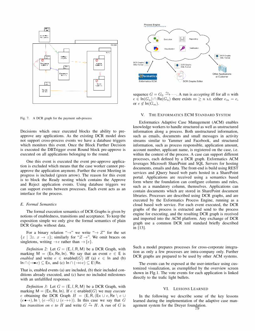
Fig. 7. A DCR graph for the payment sub-process
Decisions which once executed blocks the ability to pre-approve any applications. As the existing DCR model doesnot support cross-process events we have a database triggerswhich monitors this event. Once the Block Further Decisionis executed the DBTrigger event Round block pre-approve isexecuted on all applications belonging to the round.
One this event is executed the event pre-approve applica-tion is excluded which means that the case worker cannot pre-approve the application anymore. Further the event Meeting inprogress is included (green arrow). The reason for this eventis to block the Ready nesting which contains the Approveand Reject application events. Using database triggers wecan support events between processes. Each event acts as aninterface for the process.
E. Formal Semantics
The formal execution semantics of DCR Graphs is given bynotions of enabledness, transitions and acceptance. To keep theexposition simple we only give the formal semantics of plainDCR Graphs without data.
For a binary relation “→” we write “→ Z” for the set{x | ∃z. x → z}; similarly for “Z →”. We omit braces onsingletons, writing →e rather than →{e}.
Definition 2: Let G = (E, l,R,M) be a DCR Graph, withmarking M = (Ex,Re, In). We say that an event e ∈ E isenabled and write e ∈ enabled(G) iff (a) e ∈ In and (b)In ∩ (→•e) ⊆ Ex, and (c) In ∩ (→�e) ⊆ E\Re.
That is, enabled events (a) are included, (b) their included con-ditions already executed, and (c) have no included milestoneswith an unfulfilled responses.
Definition 3: Let G = (E, l,R,M) be a DCR Graph, withmarking M = (Ex,Re, In). If e ∈ enabled(G) we may executee obtaining the DCR Graph H = (E,R, (Ex ∪ e,Re \ e ∪(e•→), In \ (e→%) ∪ (e→+)). In this case we say that Ghas transition on e to H and write G e−→ H . A run of G is
sequence G = G0e0−→ · · ·. A run is accepting iff for all n with
e ∈ In(Gn) ∩ Re(Gn) there exists m ≥ n s.t. either em = e,or e 6∈ In(Gm).
V. THE EXFORMATICS ECM STANDARD SYSTEM
Exformatics Adaptive Case Management (ACM) enablesknowledge workers to handle structured as well as unstructuredinformation along a process. Both unstructured information,such as emails, documents and small messages in activitystreams similar to Yammer and Facebook, and structuredinformation, such as process responsible, application amount,account number, applicant name, is registered on the case, i.e.within the context of the process. A case can support differentprocesses, each defined by a DCR graph. Exformatics ACMleverages Microsoft SharePoint and SQL Servers for hostingdocuments, emails and data. The front-end is build using RESTservices and jQuery based web parts hosted in a SharePointportal. Applications are received using a semantics basedform where the foundation can configure columns and rules,such as a mandatory column, themselves. Applications cancontain documents which are stored in SharePoint documentlibraries. Processes are described using DCR graphs, and areexecuted by the Exformatics Process Engine, running as acloud based web service. For each event executed, the DCRgraphs of the process is extracted and send to the processengine for executing, and the resulting DCR graph is receivedand imported into the ACM platform. Any exchange of DCRgraph use a common DCR xml standard briefly describedin [13].
Such a model prepares processes for cross-corporate integra-tion as only a few processes are intra-company only. FurtherDCR graphs are prepared to be used by other ACM systems.
The events can be exposed at the user-interface using cus-tomized visualization, as exemplified by the overview screenshown in Flg.1. The vote events for each application is linkeddirectly to the trafic light bullets.
VI. LESSONS LEARNED
In the following we describe some of the key lessonslearned during the implementation of the adaptive case man-agement system for the Dreyer foundation.
79

A. On-the-fly Process adaptation and creation of sub pro-cesses
Since the run-time-state is simply a marking of the graph,processes can be modified on-the-fly simply by changing theDCR graph. We benefited from this to allow for payment sub-processes to be dynamically added. Initially, support for onepayment is included, which consist of the pattern of threeevents described above and shown in Fig. IV-C, which can dealwith payment errors, e.g. due to errors in Microsoft Dynamicsor the banking integration. End-users can, while the process isbeing executed, add more payments, which triggers adding apattern of events as outlined above.
Since this is an expected adaptation, it could be have beengood to have a way to model in the graph that sub-processesare dynamically added when an event, e.g. Add payment,is executed. Simliarly, each individual applications can beconsidered a sub-process of a round.
As the current DCR model does not support sub-processes,we had to implement synchronization between the round andthe set of applications using database triggers. An exampledatabase trigger can be the Round Approved, which occurson the application once the Round has been approved, whichhappens once the board meeting summary has been approved.Using a database trigger we fire this event for all applicationsof a given round once the round is approved. Creating suchdatabase triggers are not easy as we have to handle the conceptof a sub-process outside the DCR logic. The ability to describerelations between a process and its subprocesses as formalizedin the submitted paper [14] simplifies this logic, and the abilityto describe a sub-process within the context of a process wouldease the description and implementation.
A possible challenge when dealing with sub-processesidentified in the present case study, is how to handle andformalize moving an application from one round to another.This sometimes happens if the board cannot decide what to doand postpone decision to the next board meeting. This wouldlikely require formalizing passing identifies of events betweenprocesses, similar to the passing of names in the π-calculus.
This is not possible in the version of DCR Graphs im-plemented in the Exformatics tool. However, the theoreti-cal extension of dynamic creation of sub processes calledHierarchical DCR Graphs has been described in a recentlysubmitted paper [14] and implemented in a prototype, web-based simulation tool for DCR Graphs to be found at [15].
To handle un-expected additions to the process, we needsupport for end-users to define such patterns and add them to arunning process, which in the simplest case would ammount toadding (or removing) a single event or relations to a graph. Asdescribed in [13], such run-time adaptations could in principlebenefit from the formal verification supported by DCR Graphs,guaranteeing that adaptations are roboust, e.g. they do notintroduce deadlocks, livelocks or other violations of specifiedproperties. However, in practice this would require betterverification techniques than what is currently implemented.Also, if extended with dynamic creation of sub processes, DCRGraphs becomes Turing-expressive [16] which in makes ageneral verification covering all possible processes impossible.
B. Iterative, agile process design
Defining and configuring the processes in DCR graphs wasdone in several phases where more and more details wereadded. During this process the process, e.g. the application,could be simulated in the DCR drawing tool, as well as in thesystem itself. This helped end-user understand the process andfacilitated discussions on how the process should work and notwork.
Despite a detailed analysis and many end user reviews, it(of course) turned out, that a requirement was still lackingin the designed and implemented process after delivery. Therequirement that any modification to an account number re-quires accountant approval before payouts can be done wassimply missing. Adding this requirement to the graph turnedwas very easy, as we just needed to adjust the DCR graphby adding the database trigger event event Account changedwith a response relation to the approve account event, addlogic to the customer object in the database to monitor changesto account numbers, and firing the Account changed if thisoccurs. Database triggers are simple to create and understandfor such requirements and avoiding having the treatment ofaccount numbers in the graph itself.
C. Understandability
DCR graphs as supported in the current editor are hard toread and edit. Support for compositional models and zoomingin and out in details are needed for end users. Also, betterdescriptions of the DCR primitives and a modelling method-ology is needed. The condition relation is easily understood,and the required response relation is also explainable. For thepresent case, milestones, inclusion and exclusions and also thenesting of events in phases were experienced as hard to explainand understand. Some other graphical representation for many-to-many relations than the nesting is likely needed. We alsobelieve that it would be very useful if the system supportedtypical (happy) paths through the process, analalogous to anavigation system suggesting possible routes to a driver. Thesystem should be able of adjusting the proposed paths tochanging needs of the user, similar to how a navigation systemcan adapt to when a driver wants to make a detour to a gasstation.
VII. CONCLUSION AND FUTURE WORK
We have described an industrial project delivering anadaptive case management solution based on the Exformaticsstandard system and processes described as DCR Graphs.
DCR graphs have been a very valuable component toensure Exformatics ACM can support the unique processesrequired by the foundation as well as run-time modifications tothe processes as outlined in the payment event pattern. Ratherthan creating custom code the DCR graph describe the businessrules and dependencies which enables us to support uniquebusiness requirements using a standard solution. As a productcompany this is important, as managing several code baseswith unique customer requirements is too expensive.
The entire delivery was made in less than 4 months, fromthe first presentation of the requirement specification to the sys-tem as described in the present paper. The successful delivery
80
demonstrated some of the claimed benefits of DCR Graphsin practice, in particular: 1) They support agile, rule basedmodelling that can be easily adapted when new requirementsare discovered during and after delivery, 2) they support run-time addition of sub-processes which can be utilised for e.g.customised payment schemes, and 3) the resulting processesare allow maximal flexibility at run-time since they do notconstrain the flow unnecessary - if some constraints are foundunnecessary, they can simply be removed. The case studyalso demonstrated areas for future work and improvement, inparticular: 1) support for dynamic creation of sub-processesshould be part of the formal model, 2) if sub-processes areincluded in the model, formal verification of processes wouldme more likely to be possible, but we need to deal withthe fact that the model becomes Turing-expressive, 3) themodelling notation, its graphical visualisation and design toolsneed to be improved to make the models more comprehensibleand ultimately allow the business users to adapt processesthemselves in a robust way. Enabling business users to takeownership of their processes, enables businesses to developwithout changing the IT systems supporting the processes. Asbusiness processes evolves all the time we need to supportsuch changes. Having to await a new product version from avendor often does not suit the business requirement. Customerdevelopment does support the requirements either, as theirrequire IT people for development and maintenance, is verytime consuming and expensive.
ACKNOWLEDGMENT
This work was supported in part by the ComputationalArtifacts project (VELUX 33295, 2014-2017), by the DanishAgency for Science, Technology and Innovation, by Exformat-ics A/S, and by the IT University of Copenhagen. The authorswould like to thank VisualIT for their contribution to the initialrequirement elucidation.
REFERENCES
[1] M. Reichert and B. Weber, Enabling Flexibility in Process-AwareInformation Systems: Challenges, Methods, Technologies. Springer,2012.
[2] Object Management Group BPMN Technical Committee, “BusinessProcess Model and Notation, version 2.0,” http://www.omg.org/spec/BPMN/2.0/PDF.
[3] W. M. van der Aalst and M. Pesic, “DecSerFlow: Towards a trulydeclarative service flow language,” in WS-FM 2006, ser. LNCS, vol.4184. Springer, 2006, pp. 1–23.
[4] W. van der Aalst, M. Pesic, H. Schonenberg, M. Westergaard, and F. M.Maggi, “Declare,” Webpage, 2010, http://www.win.tue.nl/declare/.
[5] T. T. Hildebrandt and R. R. Mukkamala, “Declarative event-based work-flow as distributed dynamic condition response graphs,” in PLACES, ser.EPTCS, vol. 69, 2010, pp. 59–73.
[6] R. R. Mukkamala, “A formal model for declarative workflows: Dy-namic condition response graphs,” Ph.D. dissertation, IT University ofCopenhagen, June 2012.
[7] R. Hull, E. Damaggio, F. Fournier, M. Gupta, F. T. Heath, S. Hobson,M. H. Linehan, S. Maradugu, A. Nigam, P. Sukaviriya, and R. Vaculın,“Introducing the guard-stage-milestone approach for specifying businessentity lifecycles,” in WS-FM, ser. LNCS, vol. 6551. Springer, 2010,pp. 1–24.
[8] H. A. Reijers, T. Slaats, and C. Stahl, “Declarative modeling-anacademic dream or the future for bpm?” in Proceedings of 11th In-ternational Conference on Business Process Management (BPM 2013),2013, pp. 307–322.
[9] T. T. Hildebrandt, R. R. Mukkamala, and T. Slaats, “Safe distributionof declarative processes,” in SEFM, ser. LNCS, vol. 7041. Springer,2011, pp. 237–252.
[10] T. Slaats, R. R. Mukkamala, T. T. Hildebrandt, and M. Marquard,“Exformatics declarative case management workflows as DCR graphs,”in BPM, ser. LNCS, vol. 8094. Springer, 2013, pp. 339–354.
[11] T. T. Hildebrandt, M. Marquard, R. R. Mukkamala, and T. Slaats,“Dynamic condition response graphs for trustworthy adaptive casemanagement,” in OTM Workshops, ser. LNCS, vol. 8186. Springer,2013, pp. 166–171.
[12] T. Slaats, “DCR graph editor,” 2013, http://www.itu.dk/research/models/wiki/index.php/DCR Graphs Editor.
[13] R. R. Mukkamala, T. Hildebrandt, and T. Slaats, “Towards trustworthyadaptive case management with dynamic condition response graphs,”in EDOC. IEEE, 2013, pp. 127–136.
[14] S. Debois, T. Hildebrandt, and T. Slaats, “Hierarchical declarative mod-elling with refinement and sub-processes,” Submitted for publication,2014.
[15] S. Debois, “DCR exploration tool v.6,” IT University of Copen-hagen, 2014, http://www.itu.dk/research/models/wiki/index.php/DCRExploration Tool.
[16] S. Debois, T. Hildebrandt, and T. Slaats, “Dynamic conditions, restlessevents and reproduction: ω-regular languages and beyond,” Submittedfor publication, 2014.
81
5 Dynamic Condition Response Graphs with Timeand Data
82
Contracts for Cross-organizational Workflows as TimedDynamic Condition Response Graphs
Thomas Hildebrandta,1, Raghava Rao Mukkamalaa, Tijs Slaatsa,b, FrancescoZanittia
aIT University of Copenhagen, Rued Langgaardsvej 7, 2300 Copenhagen, DenmarkbExformatics A/S, 2100 Copenhagen, Denmark
Abstract
We conservatively extend the declarative Dynamic Condition Response (DCR)Graph process model, introduced in the PhD thesis of the second author, to allowfor discrete time deadlines. We prove that safety and liveness properties can beverified by mapping finite timed DCR Graphs to finite state transition systems.We exemplify how deadlines can introduce time-locks and deadlocks and violateliveness. We then prove that the general technique for safe distribution of DCRGraphs provided in previous work can be extended to timed DCR Graphs. Weexemplify the use of timed DCR Graphs and the distribution technique in praxison a timed extension of a cross-organizational case management process arisingfrom a previous case study. The example shows how a timed DCR Graph can beused to describe the global contract for a timed workflow process involving severalorganizations, which can then be distributed as a network of communicating timedDCR Graphs describing the local contract for each organization.
Key words: Time, Contracts, Declarative process models, Cross-organizationalworkflow, Safety, Liveness
Email addresses: [email protected] (Thomas Hildebrandt), [email protected] (Raghava RaoMukkamala ), [email protected] ( Tijs Slaats), [email protected] (Francesco Zanitti)
1Authors listed alphabetically. This research is supported by the Danish ResearchAgency through the Trustworthy Pervasive Healthcare Services project (grant #2106-07-0019,www.trustcare.eu), an Industrial PhD grant, and the Genie Project (grant # 2106-080046)
Preprint submitted to Logic and Algebraic Programming November 13, 2012
83
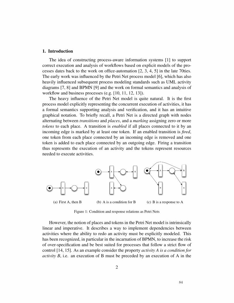
1. Introduction
The idea of constructing process-aware information systems [1] to supportcorrect execution and analysis of workflows based on explicit models of the pro-cesses dates back to the work on office-automation [2, 3, 4, 5] in the late 70ties.The early work was influenced by the Petri Net process model [6], which has alsoheavily influenced subsequent process modeling standards such as UML activitydiagrams [7, 8] and BPMN [9] and the work on formal semantics and analysis ofworkflow and business processes (e.g. [10, 11, 12, 13]).
The heavy influence of the Petri Net model is quite natural. It is the firstprocess model explicitly representing the concurrent execution of activities, it hasa formal semantics supporting analysis and verification, and it has an intuitivegraphical notation. To briefly recall, a Petri Net is a directed graph with nodesalternating between transitions and places, and a marking assigning zero or moretokens to each place. A transition is enabled if all places connected to it by anincoming edge is marked by at least one token. If an enabled transition is fired,one token from each place connected by an incoming edge is removed and onetoken is added to each place connected by an outgoing edge. Firing a transitionthus represents the execution of an activity and the tokens represent resourcesneeded to execute activities.
(a) First A, then B (b) A is a condition for B (c) B is a response to A
Figure 1: Condition and response relations as Petri Nets
However, the notion of places and tokens in the Petri Net model is intrinsicallylinear and imperative. It describes a way to implement dependencies betweenactivities where the ability to redo an activity must be explicitly modeled. Thishas been recognized, in particular in the incarnation of BPMN, to increase the riskof over-specification and be best suited for processes that follow a strict flow ofcontrol [14, 15]. As an example consider the property activity A is a condition foractivity B, i.e. an execution of B must be preceded by an execution of A in the
2
84
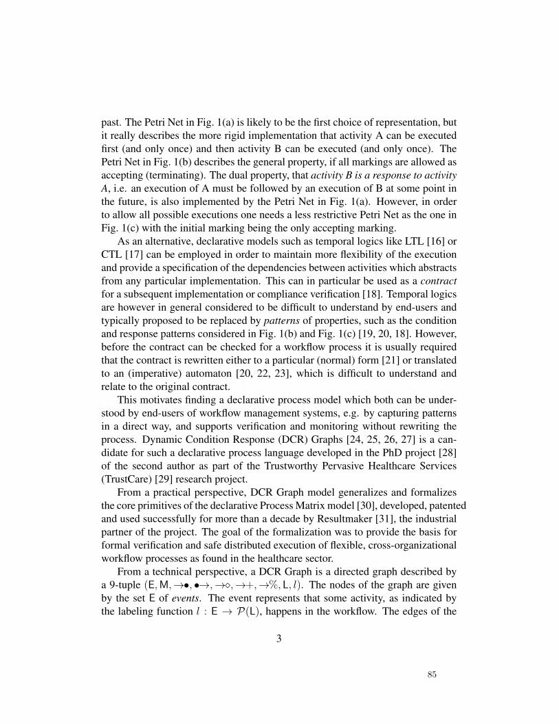
past. The Petri Net in Fig. 1(a) is likely to be the first choice of representation, butit really describes the more rigid implementation that activity A can be executedfirst (and only once) and then activity B can be executed (and only once). ThePetri Net in Fig. 1(b) describes the general property, if all markings are allowed asaccepting (terminating). The dual property, that activity B is a response to activityA, i.e. an execution of A must be followed by an execution of B at some point inthe future, is also implemented by the Petri Net in Fig. 1(a). However, in orderto allow all possible executions one needs a less restrictive Petri Net as the one inFig. 1(c) with the initial marking being the only accepting marking.
As an alternative, declarative models such as temporal logics like LTL [16] orCTL [17] can be employed in order to maintain more flexibility of the executionand provide a specification of the dependencies between activities which abstractsfrom any particular implementation. This can in particular be used as a contractfor a subsequent implementation or compliance verification [18]. Temporal logicsare however in general considered to be difficult to understand by end-users andtypically proposed to be replaced by patterns of properties, such as the conditionand response patterns considered in Fig. 1(b) and Fig. 1(c) [19, 20, 18]. However,before the contract can be checked for a workflow process it is usually requiredthat the contract is rewritten either to a particular (normal) form [21] or translatedto an (imperative) automaton [20, 22, 23], which is difficult to understand andrelate to the original contract.
This motivates finding a declarative process model which both can be under-stood by end-users of workflow management systems, e.g. by capturing patternsin a direct way, and supports verification and monitoring without rewriting theprocess. Dynamic Condition Response (DCR) Graphs [24, 25, 26, 27] is a can-didate for such a declarative process language developed in the PhD project [28]of the second author as part of the Trustworthy Pervasive Healthcare Services(TrustCare) [29] research project.
From a practical perspective, DCR Graph model generalizes and formalizesthe core primitives of the declarative Process Matrix model [30], developed, patentedand used successfully for more than a decade by Resultmaker [31], the industrialpartner of the project. The goal of the formalization was to provide the basis forformal verification and safe distributed execution of flexible, cross-organizationalworkflow processes as found in the healthcare sector.
From a technical perspective, a DCR Graph is a directed graph described bya 9-tuple (E,M,→•, •→,→�,→+,→%, L, l). The nodes of the graph are givenby the set E of events. The event represents that some activity, as indicated bythe labeling function l : E → P(L), happens in the workflow. The edges of the
3
85
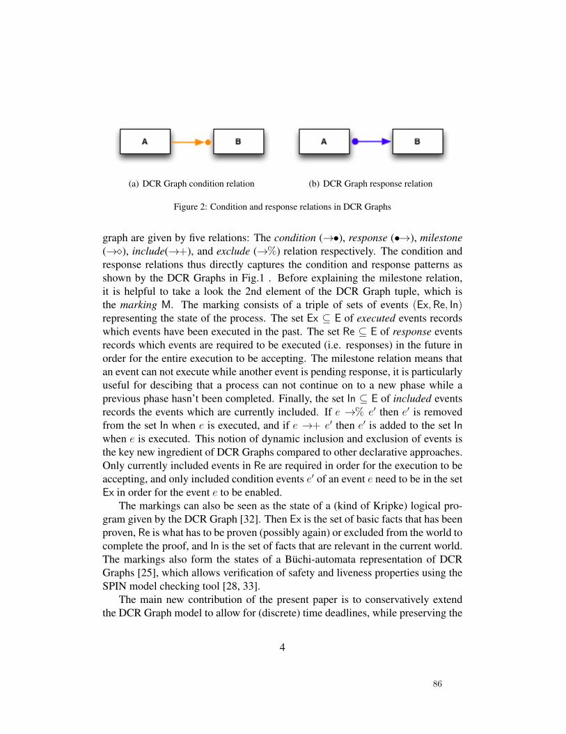
(a) DCR Graph condition relation (b) DCR Graph response relation
Figure 2: Condition and response relations in DCR Graphs
graph are given by five relations: The condition (→•), response (•→), milestone(→�), include(→+), and exclude (→%) relation respectively. The condition andresponse relations thus directly captures the condition and response patterns asshown by the DCR Graphs in Fig.1 . Before explaining the milestone relation,it is helpful to take a look the 2nd element of the DCR Graph tuple, which isthe marking M. The marking consists of a triple of sets of events (Ex,Re, In)representing the state of the process. The set Ex ⊆ E of executed events recordswhich events have been executed in the past. The set Re ⊆ E of response eventsrecords which events are required to be executed (i.e. responses) in the future inorder for the entire execution to be accepting. The milestone relation means thatan event can not execute while another event is pending response, it is particularlyuseful for descibing that a process can not continue on to a new phase while aprevious phase hasn’t been completed. Finally, the set In ⊆ E of included eventsrecords the events which are currently included. If e →% e′ then e′ is removedfrom the set In when e is executed, and if e →+ e′ then e′ is added to the set Inwhen e is executed. This notion of dynamic inclusion and exclusion of events isthe key new ingredient of DCR Graphs compared to other declarative approaches.Only currently included events in Re are required in order for the execution to beaccepting, and only included condition events e′ of an event e need to be in the setEx in order for the event e to be enabled.
The markings can also be seen as the state of a (kind of Kripke) logical pro-gram given by the DCR Graph [32]. Then Ex is the set of basic facts that has beenproven, Re is what has to be proven (possibly again) or excluded from the world tocomplete the proof, and In is the set of facts that are relevant in the current world.The markings also form the states of a Buchi-automata representation of DCRGraphs [25], which allows verification of safety and liveness properties using theSPIN model checking tool [28, 33].
The main new contribution of the present paper is to conservatively extendthe DCR Graph model to allow for (discrete) time deadlines, while preserving the
4
86

Propose
dates-LOAccept
LO
Lo
Propose
dates-DA
Accept
DA
Lo
DA DA+
+
%
%
Hold
meeting
LOOpen
case
U
3
3
3
14
ω
ω
Extend
Deadline
LO
14
14
%
%
%
Close
case
U+
Update
Case
U+
%
Figure 3: A timed DCR graph describing the global contract for a cross-organizational case man-agement system.
simple operational semantics and that safety and liveness properties of the mod-els can be formally verified by mapping the graphs to finite state Buchi-automata.Fig. 3 shows an example of a timed DCR Graph which we will use as exam-ple in the paper. The graph extends an untimed DCR Graph from a case studydescribed in [34] which captures the global requirements of a distributed, cross-organizational case management system being developed by Exformatics A/S.The system spans three different types of organizations. The first is the unionsfor employees in Denmark, which creates, closes and updates cases on behalf oftheir members (represented by the events labelled with the U and respectivelyOpen case, Close case and Update Case. The two other organizations arerespectively the umbrella organization for the unions (LandsOrganisationen, LO)and the umbrella organization for the employers (Dansk Arbejdsgiverforening,DA). When a case is created by a union, LO and DA must agree on a date for ameeting and hold the meeting within 14 days from when the case was created.The deadline is expressed by the number 14 attached to the response relation fromOpen case to Hold meeting. If the meeting is not ready to be held after 14days however, the deadline can be extended by LO by executing the event ExtendDeadline. However, this event only becomes enabled 14 days after the case hasbeen created, which is represented by the number 14 attached to the conditionrelation from Open case and Extend Deadline.
As described in [27], the DCR Graphs model admits a very general techniquefor distributing a graph describing a global contract for e.g. a cross-organizationalprocess, as a network of synchronously communicating graphs describing the con-
5
87
tracts for each local organization, and which combined describe the same processas the global contract. Another new contribution of the present paper is to extendthis technique to timed DCR Graphs and provide a detailed proof of the correct-ness of the distribution technique. It is the first step of the further developmentof the DCR Graph model and its use for specification and safe execution of dis-tributed, cross-organizational workflow processes to be carried out in the recentlyinitiated industrial PhD project of the third author.
The rest of the paper is structured as follows. In Sec. 2 below we briefly surveyrelated work. In Sec. 3 we first recall the formal definition of DCR Graphs andtheir semantics, and then proceed to define the extension to timed DCR Graphs.We then in Sec. 4 define and exemplify timed notions of safety and liveness fortimed DCR Graphs. In Sec. 5 we exemplify and provide the technique for dis-tributing a global timed DCR Graph, extending the technique for un-timed DCRGraphs given in [27]. Finally we conclude and comment on future work in Sec. 6.
2. Related Work
The DCR Graph model and graphical representation is similar to the Declareworkflow language [35, 20]. Indeed the graphical representation of events andcondition and response relations are the same in DCR Graphs and Declare. How-ever, the two approaches differ in a crucial way. While the Declare model includesa fairly rich set of patterns as relations between events based on the patterns iden-tified in [19], the DCR Graph model in addition to the condition and responserelations only allows the milestone relation and the dynamic inclusion and ex-clusion relations. Still, the DCR Graphs model is more expressive: It allows toexpress all ω-regular languages [28], while Declare only allow expressing prop-erties covered by finitary LTL. Moreover, Declare models are translated to eitherLTL or a new notion of colored automata [36] before they are verified or executed.The DCR Graph model directly supports execution of the process model based onthe simple notion of markings of the graph.
There are many researchers [10, 11, 37, 12, 13, 38, 39] who have explicitlyfocussed on the problem of verifying the correctness of inter-organizational work-flows based on variants of Petri nets. In [10], message sequence charts are usedto model the interaction between local workflows modeled as Petri nets. In [11]Kindler et. al. follows a similar approach, using a set of scenarios given as se-quence diagrams to specify the interactions. Criteria of local soundness guaranteethe global soundness of an inter-organizational workflow. In [37], so-called QueryNets based on predicate/transition Petri nets are used to guarantee global termina-
6
88
tion. Besides the use of Petri nets, a key difference between the present paper andthe work in [10, 11, 37] is that while we take a top down approach and synthesizemodels of the local workflows from a model of the global workflow, the latterwork take a bottom up approach, assuming that the models of the local workflowsare given.
A top down approach is taken in [13, 38], where a shared public view of aninter-organizational workflow given as a workflow net is partioned among the par-ticipating entities. A notion of projection inheritance is used to generate a privateview that is a subclass to the relevant public view and guarantee deadlock andlive-lock freedom. A more liberal and weaker notion than projection inheritanceis used in [12] to guarantee weak termination in multiparty contracts based onopen nets.
Modeling global behavior as a set of conversations among participating ser-vices has been studied by many researchers [40, 41, 42, 43, 44, 45] in the areabusiness processes. An approach based on guarded automata studied in [40], forthe realizability analysis of conversation protocols, whereas the authors in [41]used colored petri nets to capture the complex conversations. Similarly, but usingprocess calculus to model service contracts, Bravetti-Zavattaro proposed confor-mance notion for service composition in [44] and further enhanced their correct-ness criteria in [45] by the notion of strong service compliance. The synthesis oflocal components from a global model has also been researched for process calcu-lus formalizations of the imperative choreography language WS-CDL in the workon structured communication-centred programming for web services by Carbone,Honda and Yoshida [46]. To put it briefly, the work formalizes the core of WS-CDL as the global process calculus and defines a formal theory of end-point pro-jections projecting the global process calculus to abstract descriptions of the be-havior of each of the local ”end-points” given as pi-calculus processes typed withsession types.
Also researchers [47, 48, 49, 50] in the web services community have beenworking on web service composition and decentralized process execution usingBPEL [51] and other related technologies to model web services. A techniqueto partition a composite web service using program analysis is studied in [48]and [49] explore decomposition of a business process modeled in BPEL. Usinga formal approach based on I/O automata representing the services, the authorsin [50] study the problem of synthesizing a decentralized choreography strategy,that will have optimal overhead of service composition in terms of costs asso-ciated with each interaction. In [52, 53, 54] foundational work is presented onsynthesizing distributed transition systems from global specification for the mod-
7
89

els of synchronous product and asynchronous automata[55]. In [54] structural andbehavioral characterizations of the synthesis problem for synchronous and looselycooperating communication systems are given, based on three different notions ofequivalence: state space, language and bisimulation equivalence. Further Castel-lani et. al. [52] characterizes when an an arbitrary transition system is isomorphicto its product transition systems with a specified distribution of actions and theyhave shown that for finite state specifications, a finite state distributed implemen-tation can be synthesized. Complexity results for distributed synthesis problemsfor the three notions of equivalences were studied in [53].
A methodology for deriving process descriptions from a business contract for-malized in a formal contract language is studied in [56], while in [57] is proposedan approach to extract a distributed process model from collaborative businessprocess. In [58, 47] is proposed a technique for flexible decentralization of aprocess specification with necessary synchronization between the processing en-tities using dependency tables, whereas the authors in [59] present a frameworkfor optimizing the physical distribution of workflow schemas based on families ofcommunicating flow charts.
Common to all the approaches discussed above are that they are confined toimperative process models such as Petri nets, workflow/open nets and automata.To the best of our knowledge, there exists very few works [60, 61] that have stud-ied the synthesis problem in declarative modeling languages and none where boththe global and local processes are given declaratively. Fahland [60] studies topdown synthesis of Petri Net workflows from a limited subset of the declarativeDeclare/DecSerFlow [20] model, while Montali [61] studies the bottom-up com-position of Declare [35] models with respect to conformance with a given chore-ography.
None of the work above study synthesis or conformance of cross-organizationalworkflow with time constraints. [62] provides a good overview of various tem-poral logics that have been used for specification of real-time systems. Similar tothe extension to DCR Graph proposed in the present paper, Time Petri nets [63]extend regular Petri nets by allowing transitions to be labelled with time bounds0 ≤ a ≤ b∧a 6=∞, such that a transition can only fire after a delay of a time stepsafter it has been enabled last and must either fire or be disabled before b time haspassed. Time Petri nets have been studied as a formalism to model and verify timedependent concurrent systems in [64]. In [65, 66] the properties of reachability,boundedness and liveness for time Petri nets are studied, while [67] defines thesemantics of time Petri nets in terms of timed automata. Time Workflow nets, asubclass of time Petri nets, have been introduced in [68] as a method for modeling
8
90
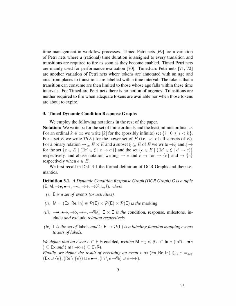
time management in workflow processes. Timed Petri nets [69] are a variationof Petri nets where a (rational) time duration is assigned to every transition andtransitions are required to fire as soon as they become enabled. Timed Petri netsare mainly used for performance evaluation [70]. Timed-arc Petri nets [71, 72]are another variation of Petri nets where tokens are annotated with an age andarcs from places to transitions are labelled with a time interval. The tokens that atransition can consume are then limited to those whose age falls within these timeintervals. For Timed-arc Petri nets there is no notion of urgency. Transitions areneither required to fire when adequate tokens are available nor when those tokensare about to expire.
3. Timed Dynamic Condition Response Graphs
We employ the following notations in the rest of the paper.Notation: We write∞ for the set of finite ordinals and the least infinite ordinal ω.For an ordinal k ∈ ∞ we write [k] for the (possibly infinite) set {i | 0 ≤ i < k}.For a set E we write P(E) for the power set of E (i.e. set of all subsets of E).For a binary relation→⊆ E × E and a subset ξ ⊆ E of E we write→ξ and ξ→for the set {e ∈ E | (∃e′ ∈ ξ | e→ e′)} and the set {e ∈ E | (∃e′ ∈ ξ | e′ → e)}respectively, and abuse notation writing → e and e → for → {e} and → {e}respectively when e ∈ E.
We first recall in Def. 3.1 the formal definition of DCR Graphs and their se-mantics.
Definition 3.1. A Dynamic Condition Response Graph (DCR Graph) G is a tuple(E,M,→•, •→,→�,→+,→%, L, l), where
(i) E is a set of events (or activities),
(ii) M = (Ex,Re, In) ∈ P(E)× P(E)× P(E) is the marking
(iii) →•, •→,→�,→+,→%⊆ E × E is the condition, response, milestone, in-clude and exclude relation respectively.
(iv) L is the set of labels and l : E→ P(L) is a labeling function mapping eventsto sets of labels.
We define that an event e ∈ E is enabled, written M `G e, if e ∈ In ∧ (In∩ →•e) ⊆ Ex and (In∩ →�e) ⊆ E\Re.Finally, we define the result of executing an event e as (Ex,Re, In) ⊕G e =def(Ex ∪ {e}, (Re \ {e}) ∪ e•→, (In \ e→%) ∪ e→+
).
9
91
Intuitively, the marking of a DCR Graph records the state. An event is then eis enabled in a marking, if it is included and every event which is a condition fore is either excluded or executed or, and every event which is a milestone for e iseither excluded or not required as a response, i.e. it is in a completed state. Belowwe give a simple example of a DCR Graph and execution of an event based on thegraph in Fig. 3.
Example 3.1. As an example consider the underlying (untimed) DCR Graph Gof the timed DCR Graph Gt in Fig. 3: the initial marking of G is M = (∅, ∅,E \{Accept LO,Accept DA,Close Case,Update Case}). The only enabled eventis Open case, all other events are either blocked through the condition relation,or not in the set of included events. After executing Open case, the new markingM′ ofG becomes: M′ = M⊕GOpen case = ({Open case}, {Propose dates-LO,Hold meeting,Close Case},E \ {Accept LO,Accept DA}). Open case isadded to the set of executed events, Close Case, Propose dates-LO and Holdmeeting are responses to Open case and therefore added to the set of pendingresponses and finally Close case and Update Case are added to the set of in-cluded events through the include relation from Open case. The enabled eventsfor M′ are Extend Deadline, Propose dates-LO, Update Case and Closecase. Note that the event Open case is not enabled because there is a milestonerelation from Close case, and Close case is in the response set. In other words,the case has to be closed by the union before it can be opened again.
We now proceed to define the conservative extension of DCR Graphs to allow(discrete) time constraints. The aim is to allow modeling interesting timed systemswhile preserving that finite DCR Graphs have tractable finite state semantics andthe technique for distribution of DCR Graphs still applies. The basic idea is toannotate response relations with discrete (possibly infinite) time constraint k ∈ ∞and condition relations with a finite time constraint j ∈ ω. A response relation
ek•→ e′ then specifies that the response event e′ must happen within k time steps
after the last time e happened. The condition relation ej→• e′ specifies that the
last time the condition event e happened must be at least j time steps before e′
can happen. That is, the time constraint eω•→ e′ means that the event e′ should
happen eventually after e happens, and the time constraint e0→• e′ means that
event e should have happened before e′ can happen, corresponding to respectivelythe response and condition constraints in un-timed DCR Graphs. For this reasonwe often write e •→ e′ for e
ω•→ e′ and e→• e′ for e0→• e′.
10
92

To be able to evaluate the timed constraints we extend markings to includetwo functions, a function tex : Ex→ ω recording the time since the event was lastexecuted, and tre : Re→∞ recording the time deadline of the pending responses.
If there exists a maximal condition deadline, which is always the case if thetimed DCR Graph is finite, we say that it is bounded. For bounded timed DCRGraphs we only need to record the time since last execution if it is below the max-imal time constraint and otherwise record it as the maximal condition deadline.
Definition 3.2. A Timed Dynamic Condition Response Graph (Timed DCR Graph)G is a tuple (E,Mt,→•, tc, •→, tr,→�,→+,→%, L, l), where
(i) Mt = (M, tex, tre) ∈ M(G) is the timed marking, forM(G) =def (P(E)×P(E)× P(E))× Ex→ ω × Re→∞ if M = (Ex,Re, In),
(ii) (E,M,→•, •→,→�,→+,→%, L, l) is a DCR Graph, referred to as the un-derlying DCR Graph,
(iii) tex : Ex→ ω is the time since the event happened,
(iv) tre : Re→∞ is the maximal time deadline of the required response,
(v) tc : (→•)→ ω is the (minimal) required time delay since the condition eventhappened,
(vi) tr : (•→)→∞ is the maximal time deadline of the response event.
We write ek•→ e′ for e •→ e′ and tr(e, e′) = k and similarly write e
k→• e′ fore→• e′ and tc(e, e′) = k. We define the maximal condition delay as maxcG =def
sup{k | ∃e, e′ ∈ E.ek→• e′} and the minimal included response deadline by
minrG = min{tre(e) | ∃e ∈ Re ∩ In}.
Notation: We introduce the following shorthand notation for annotating the eventsin the executed and response sets with the their timestamp according to respec-tively tex and tre: For a marking Mt = (({e1, e2}, {e2, e3}, In), tex, tre) we write({e1 : tex(e1), e2 : tex(e2)}, {e2 : tre(e2), e3 : tre(e3)}, In).
In Def. 3.3 below we formalize when events are enabled and the result ofexecuting an event in a timed DCR Graph. An event e is enabled in a timed DCRGraph if it is enabled in the underlying un-timed DCR Graph and for all condition
events e′k→• e the time tex(e′) since the last execution of e′ is greater or equal than
11
93
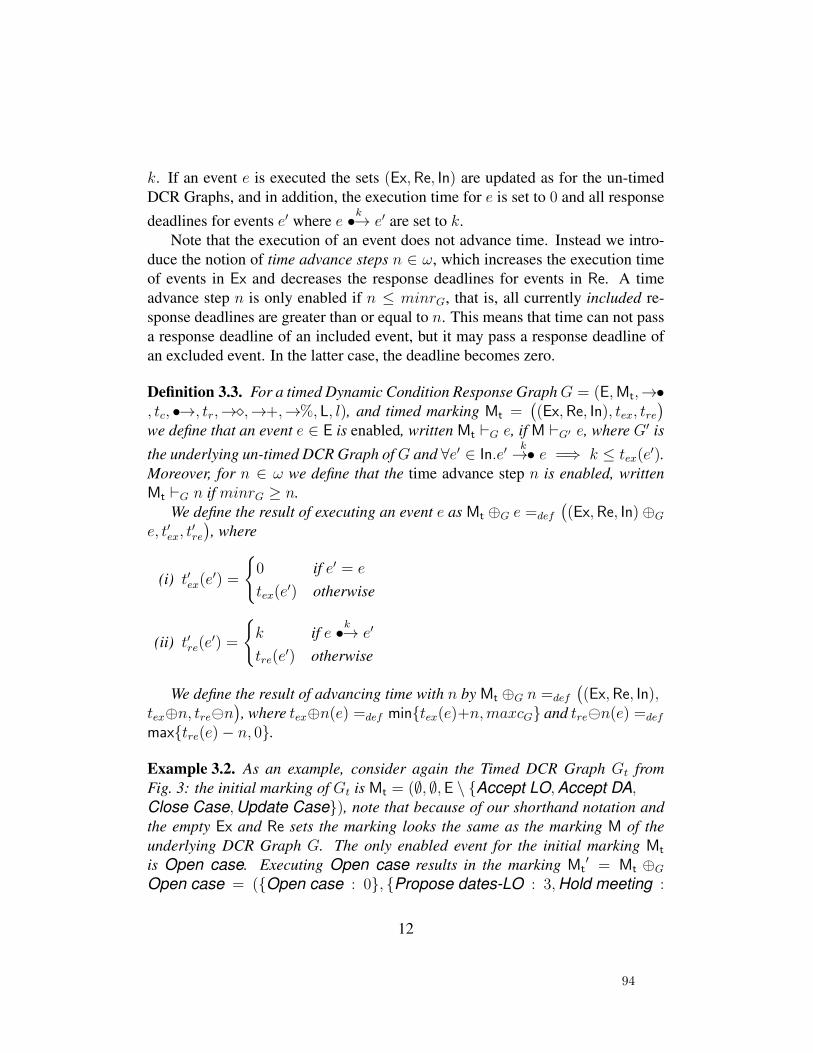
k. If an event e is executed the sets (Ex,Re, In) are updated as for the un-timedDCR Graphs, and in addition, the execution time for e is set to 0 and all response
deadlines for events e′ where ek•→ e′ are set to k.
Note that the execution of an event does not advance time. Instead we intro-duce the notion of time advance steps n ∈ ω, which increases the execution timeof events in Ex and decreases the response deadlines for events in Re. A timeadvance step n is only enabled if n ≤ minrG, that is, all currently included re-sponse deadlines are greater than or equal to n. This means that time can not passa response deadline of an included event, but it may pass a response deadline ofan excluded event. In the latter case, the deadline becomes zero.
Definition 3.3. For a timed Dynamic Condition Response GraphG = (E,Mt,→•, tc, •→, tr,→�,→+,→%, L, l), and timed marking Mt =
((Ex,Re, In), tex, tre
)
we define that an event e ∈ E is enabled, written Mt `G e, if M `G′ e, where G′ is
the underlying un-timed DCR Graph ofG and ∀e′ ∈ In.e′k→• e =⇒ k ≤ tex(e
′).Moreover, for n ∈ ω we define that the time advance step n is enabled, writtenMt `G n if minrG ≥ n.
We define the result of executing an event e as Mt ⊕G e =def
((Ex,Re, In)⊕G
e, t′ex, t′re
), where
(i) t′ex(e′) =
{0 if e′ = e
tex(e′) otherwise
(ii) t′re(e′) =
{k if e
k•→ e′
tre(e′) otherwise
We define the result of advancing time with n by Mt ⊕G n =def
((Ex,Re, In),
tex⊕n, tren), where tex⊕n(e) =def min{tex(e)+n,maxcG} and tren(e) =def
max{tre(e)− n, 0}.
Example 3.2. As an example, consider again the Timed DCR Graph Gt fromFig. 3: the initial marking of Gt is Mt = (∅, ∅,E \ {Accept LO,Accept DA,Close Case,Update Case}), note that because of our shorthand notation andthe empty Ex and Re sets the marking looks the same as the marking M of theunderlying DCR Graph G. The only enabled event for the initial marking Mt
is Open case. Executing Open case results in the marking Mt′ = Mt ⊕G
Open case = ({Open case : 0}, {Propose dates-LO : 3,Hold meeting :
12
94

14,Close Case : ω},E \ {Accept LO,Accept DA}). Except for the timed partMt’ is the same as M’ that resulted from executing Open case on the underlyingDCR Graph G. In the timed marking we also record the time that has passedsince Open case was executed and the deadlines for which the responses onPropose dates-LO, Hold meeting and Close case need to be satisfied. Notethat unlike the untimed example Extend Deadline is not enabled because of thetime constraint on the condition.
The timed response on Propose dates-LO limits the time to advance from themarking Mt’ to a maximum of 3 steps. Doing a time advance step of size 3 resultsin the new marking Mt
′′ = Mt′⊕G3 = ({Open case : 3}, {Propose dates-LO :
0,Hold meeting : 11,Close Case : ω},E \ {Accept LO,Accept DA}). Wecan now no longer advance time before Propose dates-LO has been executed orexcluded.
It follows directly from the definition above that if an event is enabled in atimed DCR Graph then it is also enabled in the underlying (un-timed) DCR Graph.Moreover, the result on the sets (Ex,Re, In) in the marking when executing anevent in a timed DCR Graph is the same as when it is executed in the underlyingDCR Graph and time advance steps do not change the marking of the underlyingDCR Graph. Conversely, a DCR Graph G can be regarded as a timed DCR GraphGt havingG as the underlying DCR Graph and all condition delays (and executiontimes in the marking) 0 and all response deadlines (in the graph and the marking)ω. It then holds that, if an event is enabled in the DCR Graph G, then it is alsoenabled in the corresponding timed DCR Graph Gt. Moreover, the executiontimes and response deadlines in the marking will always be 0 and ω respectively.
We define in Def. 3.4 timed (must) executions and the corresponding labelledtransition system for timed DCR Graphs as for un-timed DCR Graphs, except thatexecutions can now also contain time advance steps. Moreover, for an executionto be accepting it is required that it is accepting in the underlying DCR Graphand moreover contains infinitely many time advance steps. Thus, an acceptingexecution may contain only finitely many events, but then it will after the lastevent contain an infinite sequence of time advance steps. It follows directly that(accepting) executions in a timed DCR Graph correspond to (accepting) execu-tions in the underlying DCR Graph (where the time advance steps are removed).Moreover, an (accepting) execution in a DCR Graph G will have infinitely manycorresponding (accepting) executions in the corresponding timed DCR Graph Gt
obtained by interleaving the untimed execution with any infinite sequence of timeadvance steps.
13
95
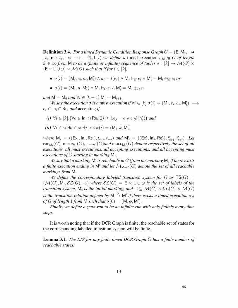
Definition 3.4. For a timed Dynamic Condition Response GraphG = (E,Mt,→•, tc, •→, tr,→�,→+,→%, L, l) we define a timed execution σM of G of lengthk ∈ ∞ from M to be a (finite or infinite) sequence of tuples σ : [k] → M(G) ×(E× L ∪ ω)×M(G) such that if for i ∈ [k],
• σ(i) = (Mi, ei, ai,M′i) ∧ ai = l(ei) ∧Mi `G ei ∧M′i = Mi ⊕G ei or
• σ(i) = (Mi, n,M′i) ∧Mi `G n ∧M′i = Mi ⊕G n
and M = M0 and ∀i ∈ [k − 1].M′i = Mi+1.We say the execution σ is a must execution if ∀i ∈ [k].σ(i) = (Mi, ei, ai,M
′i) =⇒
ei ∈ Ini ∩ Rei and accepting if
(i) ∀i ∈ [k].(∀e ∈ Ini ∩ Rei.∃j ≥ i.ej = e ∨ e 6∈ In′j)
)and
(ii) ∀i ∈ ω.∃k ∈ ω.∃j > i.σ(i) = (Mi, k,M′i)
where Mi = ((Exi, Ini,Rei), texi, trei) and M′j = ((Ex′j, In′j,Re′j), t
′exj, t
′rej). Let
exeMt(G), mexeMt(G), accMt(G)and maccMt(G) denote respectively the set of allexecutions, all must executions, all accepting executions, and all accepting mustexecutions of G starting in marking Mt.
We say that a marking M′ is reachable inG (from the marking M) if there existsa finite execution ending in M′ and letMM→∗(G) denote the set of all reachablemarkings from M.
We define the corresponding labeled transition system for G as TS(G) =(M(G),Mt, EL(G),→) where EL(G) = E × L ∪ ω is the set of labels of thetransition system, Mt is the initial marking, and→⊆ M(G) × EL(G) ×M(G)
is the transition relation defined by Mφ−→ M′ if there exists a timed execution σM
of G of length 1 from M such that σ(0) = (M, φ,M′).Finally we define a zeno-run to be an infinite run with only finitely many time
steps.
It is worth noting that if the DCR Graph is finite, the reachable set of states forthe corresponding labelled transition system will be finite.
Lemma 3.1. The LTS for any finite timed DCR Graph G has a finite number ofreachable states.
14
96
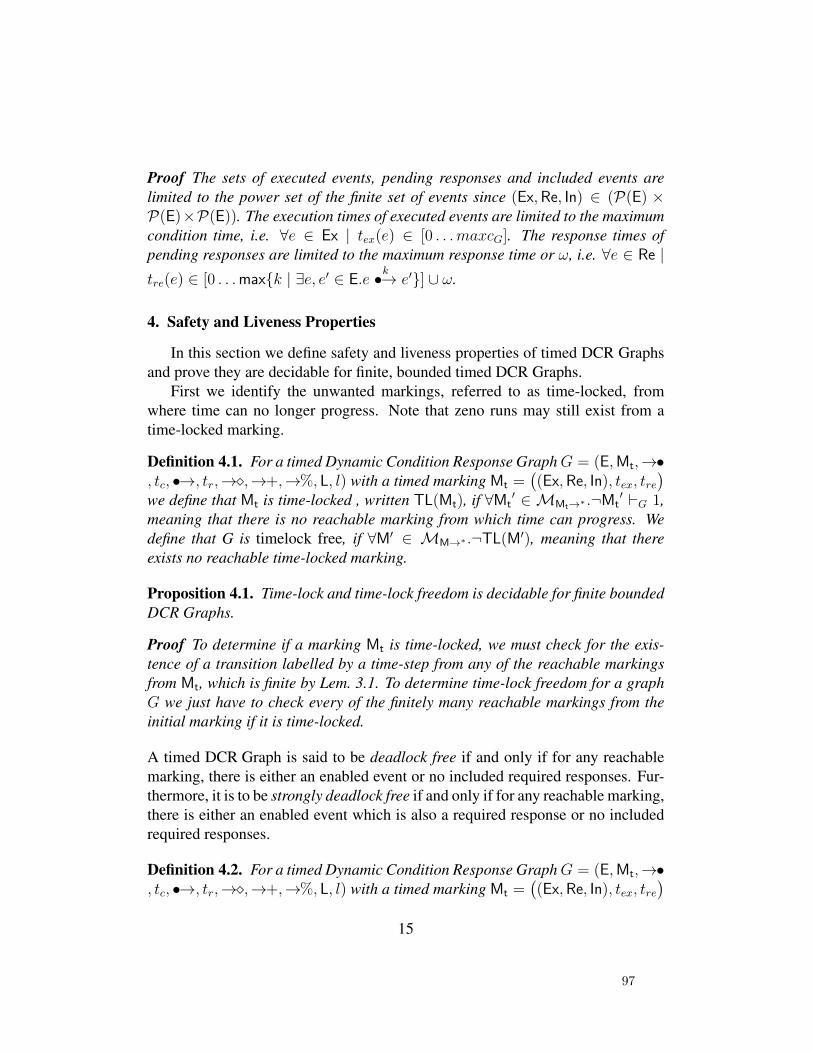
Proof The sets of executed events, pending responses and included events arelimited to the power set of the finite set of events since (Ex,Re, In) ∈ (P(E) ×P(E)×P(E)). The execution times of executed events are limited to the maximumcondition time, i.e. ∀e ∈ Ex | tex(e) ∈ [0 . . .maxcG]. The response times ofpending responses are limited to the maximum response time or ω, i.e. ∀e ∈ Re |tre(e) ∈ [0 . . .max{k | ∃e, e′ ∈ E.e
k•→ e′}] ∪ ω.
4. Safety and Liveness Properties
In this section we define safety and liveness properties of timed DCR Graphsand prove they are decidable for finite, bounded timed DCR Graphs.
First we identify the unwanted markings, referred to as time-locked, fromwhere time can no longer progress. Note that zeno runs may still exist from atime-locked marking.
Definition 4.1. For a timed Dynamic Condition Response GraphG = (E,Mt,→•, tc, •→, tr,→�,→+,→%, L, l) with a timed marking Mt =
((Ex,Re, In), tex, tre
)
we define that Mt is time-locked , written TL(Mt), if ∀Mt′ ∈ MMt→∗ .¬Mt
′ `G 1,meaning that there is no reachable marking from which time can progress. Wedefine that G is timelock free, if ∀M′ ∈ MM→∗ .¬TL(M′), meaning that thereexists no reachable time-locked marking.
Proposition 4.1. Time-lock and time-lock freedom is decidable for finite boundedDCR Graphs.
Proof To determine if a marking Mt is time-locked, we must check for the exis-tence of a transition labelled by a time-step from any of the reachable markingsfrom Mt, which is finite by Lem. 3.1. To determine time-lock freedom for a graphG we just have to check every of the finitely many reachable markings from theinitial marking if it is time-locked.
A timed DCR Graph is said to be deadlock free if and only if for any reachablemarking, there is either an enabled event or no included required responses. Fur-thermore, it is to be strongly deadlock free if and only if for any reachable marking,there is either an enabled event which is also a required response or no includedrequired responses.
Definition 4.2. For a timed Dynamic Condition Response GraphG = (E,Mt,→•, tc, •→, tr,→�,→+,→%, L, l) with a timed marking Mt =
((Ex,Re, In), tex, tre
)
15
97
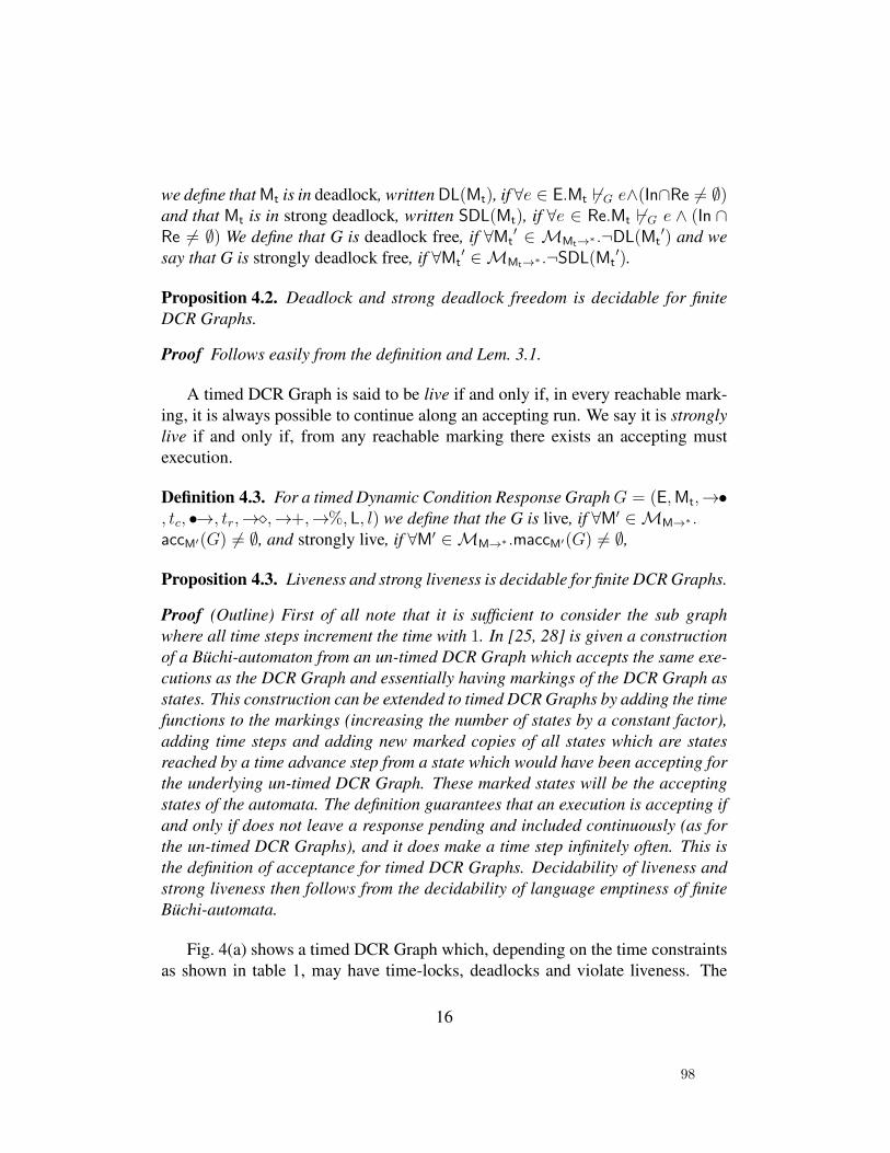
we define that Mt is in deadlock, written DL(Mt), if ∀e ∈ E.Mt 6`G e∧(In∩Re 6= ∅)and that Mt is in strong deadlock, written SDL(Mt), if ∀e ∈ Re.Mt 6`G e ∧ (In ∩Re 6= ∅) We define that G is deadlock free, if ∀Mt
′ ∈ MMt→∗ .¬DL(Mt′) and we
say that G is strongly deadlock free, if ∀Mt′ ∈MMt→∗ .¬SDL(Mt
′).
Proposition 4.2. Deadlock and strong deadlock freedom is decidable for finiteDCR Graphs.
Proof Follows easily from the definition and Lem. 3.1.
A timed DCR Graph is said to be live if and only if, in every reachable mark-ing, it is always possible to continue along an accepting run. We say it is stronglylive if and only if, from any reachable marking there exists an accepting mustexecution.
Definition 4.3. For a timed Dynamic Condition Response GraphG = (E,Mt,→•, tc, •→, tr,→�,→+,→%, L, l) we define that the G is live, if ∀M′ ∈MM→∗ .accM′(G) 6= ∅, and strongly live, if ∀M′ ∈MM→∗ .maccM′(G) 6= ∅,
Proposition 4.3. Liveness and strong liveness is decidable for finite DCR Graphs.
Proof (Outline) First of all note that it is sufficient to consider the sub graphwhere all time steps increment the time with 1. In [25, 28] is given a constructionof a Buchi-automaton from an un-timed DCR Graph which accepts the same exe-cutions as the DCR Graph and essentially having markings of the DCR Graph asstates. This construction can be extended to timed DCR Graphs by adding the timefunctions to the markings (increasing the number of states by a constant factor),adding time steps and adding new marked copies of all states which are statesreached by a time advance step from a state which would have been accepting forthe underlying un-timed DCR Graph. These marked states will be the acceptingstates of the automata. The definition guarantees that an execution is accepting ifand only if does not leave a response pending and included continuously (as forthe un-timed DCR Graphs), and it does make a time step infinitely often. This isthe definition of acceptance for timed DCR Graphs. Decidability of liveness andstrong liveness then follows from the decidability of language emptiness of finiteBuchi-automata.
Fig. 4(a) shows a timed DCR Graph which, depending on the time constraintsas shown in table 1, may have time-locks, deadlocks and violate liveness. The
16
98
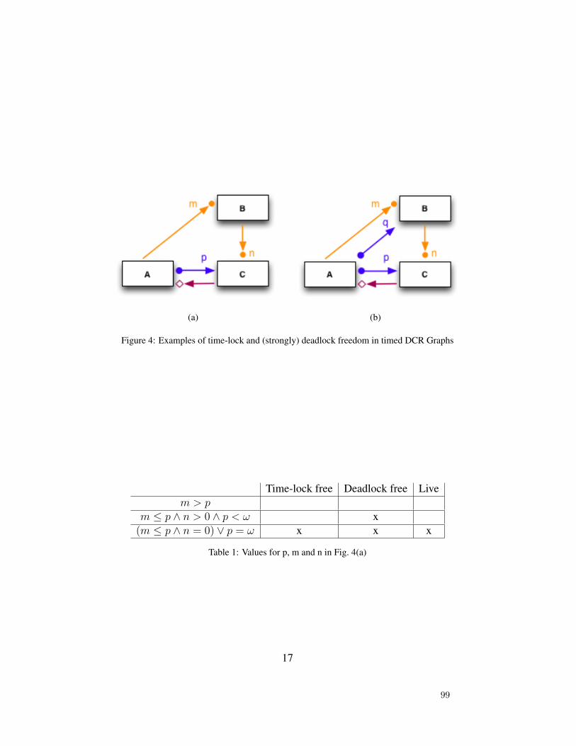
(a) (b)
Figure 4: Examples of time-lock and (strongly) deadlock freedom in timed DCR Graphs
Time-lock free Deadlock free Livem > p
m ≤ p ∧ n > 0 ∧ p < ω x(m ≤ p ∧ n = 0) ∨ p = ω x x x
Table 1: Values for p, m and n in Fig. 4(a)
17
99
graph consist of three events: A, B, and C. The event A is a condition for B, andthe time deadline requires that the last execution of Amust have happenedm timesteps before B can happen. Similarly, the B is a condition for C, and the timedeadline requires that the last execution of B must have happened n time stepsbefore B can happen. The event C is a response to the event A, and the deadlinerequires that it must happen within p time steps after the last execution of A. Themilestone relation from C to A is a kind of alternation pattern, it enforces that Acan not happen as long as C is required as a response, i.e. two As can not happenwithout at least one C in between.
Now, if m > p then the graph enters both a marking which is both time-locked and deadlocked if A happens and time advances with p steps. Since B isa condition for C it must be executed before C can be executed, but this is notpossible since the delay constraint m is greater than p. The event A can not beexecuted before C has been executed due to the milestone relation, thus we havea deadlock. And since C is required urgently, i.e. within deadline 0, time can notprogress either, i.e. we have a time-lock.
This deadlock can be resolved if m ≤ p. Then B can be executed before thedeadline p expires, and we can repeat doingB infinitely often. However, the graphmay still contain a time-lock, and thus also violate liveness: If n > 0 and p < ωand we do B exactly p time steps after A, then we can not do C since it requiresa delay of n > 0 after the execution of B, and time can not progress because Cis required urgently, i.e. within deadline 0. The time-lock is resolved if n = 0 orp = ω, since then we can either do C just after B (without advancing time) or thedeadline on C will never expire and lead to time-lock.
The graph in Fig. 4(a) is neither strongly deadlock free nor strongly live forany of the parameters. If A is executed it is not possible to execute C if onlyrequired events are executed. This can be resolved by making B a response to Aas shown in Fig. 4(b). Strongly deadlock and live DCR Graphs may be needed ifthe process is distributed between different roles as considered in the next section.If A and B are carried out by role N , and C by role M , then role N may believethat it is not necessary to do more after doing A. However, role M will then bestuck with a required action C which is blocked because B has not been executed.
5. Timed DCR Graphs as Global Contracts
The DCR Graphs model admits a very general technique for distributing agraph describing a global contract for e.g. a cross-organizational process, as a net-work of synchronously communicating graphs describing the contracts for each
18
100
local organization [27]. The technique is based on a notion of projection, restrict-ing the graph to a subset of the events and labels. The projection introduces anotion of interface events, that can be regarded as a subscription to executions ofevents in other components.
In Fig. 5 it is shown how the technique can be used to project the global graphin Fig. 3 to three local graphs, representing the part of the process to be carried outby respectively the unions (U), the umbrella organization for the unions (LandsOr-ganisationen, LO) and the umbrella organization for the employers (Dansk Arbe-jdsgiverforening, DA). The Open case event with the double border in the LOlocal graph indicate that it needs to subscribe to the event Open case in order toknow when it can and must propose dates and hold a meeting. The unions on theother hand need not subscribe to any external events, they only need to considertheir own events Open case, Close case and Update case.
5.1. ProjectionFirst we define how to project a DCR Graph G with respect to a projection
parameter δ = (δE, δL) where δE ⊆ E is a subset of the events of G and δL ⊆ L isa subset of the labels.
Intuitively, the projection G|δ contains only those events and relations that arerelevant for the execution of events in δE and the labeling is restricted to the setδL. This includes both the events in δE and any other event that can affect themarking, or the ability to execute an event in δE. The technical difficulty is toinfer the events and relations not in δE, referred to as external events below, thatshould be included in the projection because they influence the execution of theworkflow restricted to the events in δE. The external events are never executed bythe local component but can be executed by other components, in which case thelocal component must be notified so that it can update its marking accordingly.
Definition 5.1. If G = (E,Mt,→•, tc, •→, tr,→�,→+,→%, L, l) then G|δ =(E|δ,Mt|δ,→•|δ, tc|δ, •→|δ, tr|δ,→�|δ,→+|δ,→%|δ, δL, l|δ) is the projection of Gwith respect to δ = (δE, δL), δE ⊆ E and δL ⊆ L where:
(i) E|δ =→ δE, for →=⋃
c∈Cc, and C = {id, →•, •→, →�, →+, →%, •→→�,
→+→•,→%→•,→+→�,→%→�}
(ii) l|δ(e) =
{l(e) ∩ δL if e ∈ δE
∅ otherwise
19
101

(iii) Mt|δ = ((Ex|δ,Re|δ, In|δ), tex|δ, tre|δ) where:
(a) Ex|δ = Ex ∩ E|δ
(b) Re|δ = Re ∩ (δE∪ →� δE)
(c) In|δ = In ∩ (δE∪ →• δE∪ →� δE)
(d) tex|δ (e) = tex (e) if e ∈ Ex|δ
(e) tre|δ (e) = tre (e) if e ∈ Re|δ
(iv) →•|δ=→• ∩((→• δE)× δE)
(v) tc|δ : (→•|δ)→ ωtc|δ (e, e′) = tc (e, e′)
(vi) •→|δ=•→ ∩((•→→� δE)× (→� δE)) ∪ ((•→ δE)× δE))
(vii) tr|δ : (•→|δ)→∞tr|δ (e, e′) = tr (e, e′)
(viii) →�|δ=→� ∩((→� δE)× δE)
(ix) →+|δ=→+ ∩((
(→+ δE) × δE
)∪((→+→• δE) × (→• δE
)∪((→+→�
δE)× (→� δE
))
(x) →%|δ=→% ∩((
(→% δE) × δE
)∪((→%→• δE) × (→• δE
)∪((→%→�
δE)× (→� δE
))
In (i) we define the set of events as the union of the set δE of events that weproject over, any event that has a direct relation towards an event in δE and eventsthat exclude or include an event which is either a condition or a milestone foran event in δE. The additional events will be included in the projection withoutlabels, as can be seen from the definition of the labeling function in (??). Thismeans that the events can not be executed locally. However, when composed in anetwork containing other processes that can execute these events, their executionwill be communicated to the process. For this reason we refer to these events asthe (additional) external events of the projection. As proven in Prop. A.1-A.3 thecommunication of the execution of this set of external events in addition to the
20
102
local events shared by others ensures that the local state of the projection staysconsistent with the global state.
Further (iii) defines the projection of the marking: The executed events remainthe same, but are limited to the events in E|δ. The responses are restricted to eventsin δE and events that have a milestone relation to an event in δE because these arethe only responses that will affect the local execution of the projected graph. Notethat these events will by definition be events in E|δ but may be external events. Incase of set of included events, we take the actual included status of the events inprojection parameter along with the events that are conditions and milestones tothe events in projection parameter, as the include status of those events will havean influence on the execution of events in local graph. All other external events ofthe projected graph are not included in the projected marking regardless of theirincluded status in the marking of the global graph, because their include/excludestatus will have no influence on the execution of events in local graph.
Finally, (iv), (vi), (viii), (ix) and (x) state which relations should be includedin the projection. For the events in δE all incoming relations should be included.Additionally inclusion and exclusion relations to events that are either a conditionor a milestone for an event in δE are included as well.
Fig. 5 shows how the case management example from fig. 3 can be pro-jected over the three roles. The projection parameters for these projections are:δU = ({Open case,Update Case}, {(Open case,U), (Update Case,U)}),δLO = ({Propose Dates - LO,Accept LO,Extend Deadline,Hold Meeting},{(Propose Dates - LO,LO), (Accept LO,LO), (Extend Deadline,LO),(Hold Meeting,LO)}) and δDA = ({Propose Dates - DA,Accept DA},{(Propose Dates - DA,DA), (Accept DA,DA)}). From the figure one can seethat the union needs to know nothing about the global contract. It can only open,close and update the case and because these events are not depending on any ofthe events of LO and DA, the union does not have to be aware of any other events.LO on the other hand needs to know about most of the events and relations in thecontract because many of its internal events depend directly on events of the unionor DA. This reflects the role of LO as an intermediary between the union and DA,which gives it a central role in the process. DA is only involved in arranging ameeting and needs to be aware of a few of the events of LO to properly play itsrole in this, but all other events that do not directly affect the meeting arrange-ment part of the contract are not relevant for DA and therefore do not have to beprojected to the local graph for DA.
Prop. 5.1 below states the key correspondence between global execution ofevents and the local execution of events in a projection. We have provided the
21
103
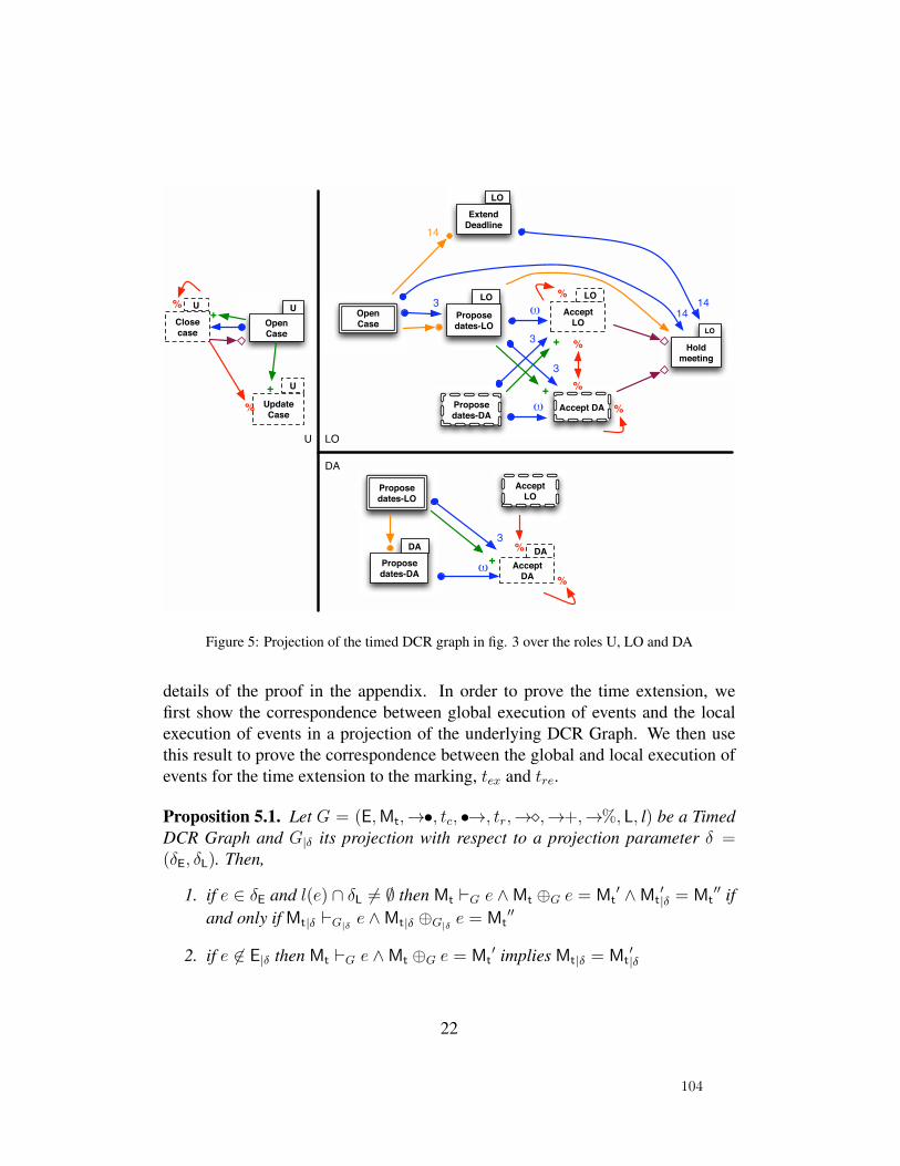
Hold
meeting
LOOpen
Case
U
Update
Case
U
Propose
dates-LO
Accept
LO
LO
Propose
dates-DA
LO
Open
Case
+
+
LOU
3
%
%
Accept DA
ω
Extend
Deadline
LO
14
14
14
3
3
ω
%
%
+
3
ω
%
%
Propose
dates-LO
Accept
LO
Propose
dates-DA
DA
Accept
DA
DA
DA
%
Close
case
U+
+
%
Figure 5: Projection of the timed DCR graph in fig. 3 over the roles U, LO and DA
details of the proof in the appendix. In order to prove the time extension, wefirst show the correspondence between global execution of events and the localexecution of events in a projection of the underlying DCR Graph. We then usethis result to prove the correspondence between the global and local execution ofevents for the time extension to the marking, tex and tre.
Proposition 5.1. Let G = (E,Mt,→•, tc, •→, tr,→�,→+,→%, L, l) be a TimedDCR Graph and G|δ its projection with respect to a projection parameter δ =(δE, δL). Then,
1. if e ∈ δE and l(e) ∩ δL 6= ∅ then Mt `G e ∧Mt ⊕G e = Mt′ ∧Mt
′|δ = Mt
′′ ifand only if Mt|δ `G|δ e ∧Mt|δ ⊕G|δ e = Mt
′′
2. if e 6∈ E|δ then Mt `G e ∧Mt ⊕G e = Mt′ implies Mt|δ = Mt
′|δ
22
104
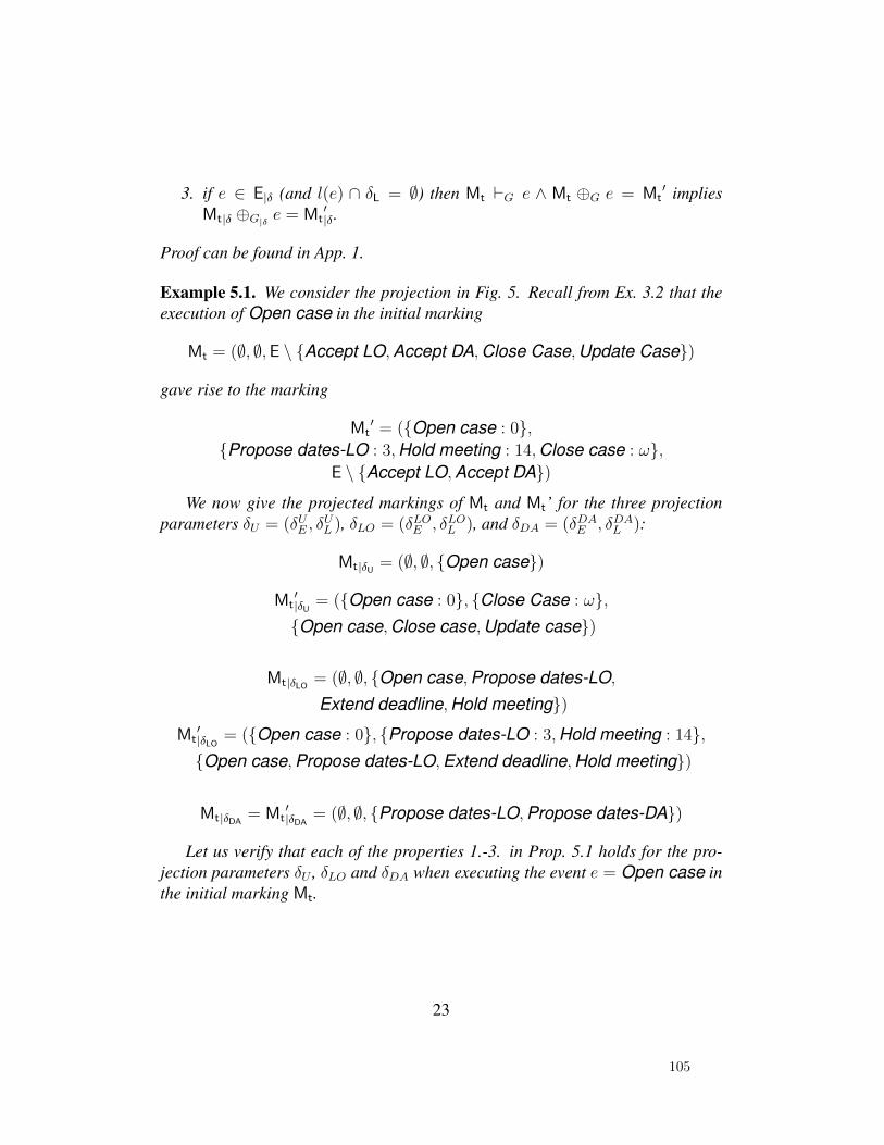
3. if e ∈ E|δ (and l(e) ∩ δL = ∅) then Mt `G e ∧ Mt ⊕G e = Mt′ implies
Mt|δ ⊕G|δ e = Mt′|δ.
Proof can be found in App. 1.
Example 5.1. We consider the projection in Fig. 5. Recall from Ex. 3.2 that theexecution of Open case in the initial marking
Mt = (∅, ∅,E \ {Accept LO,Accept DA,Close Case,Update Case})
gave rise to the marking
Mt′ = ({Open case : 0},
{Propose dates-LO : 3,Hold meeting : 14,Close case : ω},E \ {Accept LO,Accept DA})
We now give the projected markings of Mt and Mt’ for the three projectionparameters δU = (δUE , δ
UL ), δLO = (δLOE , δLOL ), and δDA = (δDAE , δDAL ):
Mt|δU= (∅, ∅, {Open case})
Mt′|δU
= ({Open case : 0}, {Close Case : ω},{Open case,Close case,Update case})
Mt|δLO= (∅, ∅, {Open case,Propose dates-LO,Extend deadline,Hold meeting})
Mt′|δLO
= ({Open case : 0}, {Propose dates-LO : 3,Hold meeting : 14},{Open case,Propose dates-LO,Extend deadline,Hold meeting})
Mt|δDA= Mt
′|δDA
= (∅, ∅, {Propose dates-LO,Propose dates-DA})
Let us verify that each of the properties 1.-3. in Prop. 5.1 holds for the pro-jection parameters δU , δLO and δDA when executing the event e = Open case inthe initial marking Mt.
23
105
1. This property applies to the projection over the union because e ∈ δUE and
l(e) ∩ δUL 6= ∅. First of all the property requires us to verify that e is only
enabled in the global graph if and only if it is enabled in the local graph.This is the case because both Mt `G e and Mt|δU
`G e. Secondly theproperty requires us to verify that the result of executing e on the globalgraph and then projecting the resulting marking over δU is the same asexecuting e on the projected graph. This is the case because: Mt|δU
⊕G|δUe =
Mt′|δU
.
2. This property applies to the projection over DA because e 6∈ E|δDA. It re-
quires us to verify that if e does not occur in the events of the projectedgraph G|δDA
, then the marking projected over δDA will be the same beforeand after the execution of e. This is the case because Mt|δDA
= Mt′|δDA
.
3. This property applies to the projection over LO because e ∈ E|δLOand
l(e) ∩ δLOL = ∅. It requires us to show that if e is an external event in
the projected graph G|δLO, then it must be the case that if we execute e on
G|δLO, the resulting marking must be the same as if we had first executed
e on G and then projected the result over δLO. This is the case becauseMt|δLO
⊕G|δLOe = Mt
′|δLO
.
5.2. CompositionNow we define the binary composition of two DCR Graphs. The composition
of G1 and G2 is simply the component-wise union of the respective components.
Definition 5.2. G1 ∪ G2 = (E1 ∪ E2,Mt,→•1 ∪ →•2, tc1 ∪ tc2, •→1 ∪ •→2
, tr1 ∪ tr2,→�1 ∪ →�2,→+1 ∪ →+2,→%1 ∪ →%2, L1 ∪ L2, l1 ∪ l2), whereMt = ((Ex1 ∪ Ex2,Re1 ∪ Re2, In1 ∪ In2), tex1 ∪ tex2, tre1 ∪ tre2)
Definition 5.3. The composition G1 ∪ G2 is well-defined when:
(i) ∀(e ∈ E1 ∩ E2 | (e ∈ Ex1 ⇔ e ∈ Ex2))
(ii) ∀(e ∈ (Ei1∪ →•Ei
1∪ →�Ei1) ∩ (Ei
2∪ →•Ei2∪ →�Ei
2) | (e ∈ In1 ⇔ e ∈ In2)
(iii) ∀(e ∈ (Ei1∪ →�Ei
1) ∩ (Ei2∪ →�Ei
2) | (e ∈ Re1 ⇔ e ∈ Re2)
(iv) ∀(e ∈ Ex1 ∩ Ex2 | (tc1 e = tc2 e))
(v) ∀(e ∈ Re1 ∩ Re2 | (tr1 e = tr2 e))
24
106
(vi) ∀(e, e′ ∈→•1 ∩ →•2| tc1(e, e′) = tc2(e, e′))
(vii) ∀(e, e′ ∈•→1 ∩ •→2| tr1(e, e′) = tr2(e, e′))
Where: Eii = {e ∈ Ei | l(e) 6= ∅} for i ∈ {1, 2}
(i) ensures that those events that will be glued together have the same exe-cution marking. (ii) ensures that events that will be glued together and in bothDCR Graphs belong to either the set of internal events or the set of events thathave a condition/milestone relation towards an internal event, have the same in-clusion marking. (iii) ensures that events that will be glued together and in bothDCR Graphs belong to the set of internal events have the same pending responsemarking. (iv) ensures that executed events that will be glued together have thesame timed execution marking. (v) ensures that responses on events that will beglued together have the same deadline. (vi) ensures that shared conditions havethe same required time delay. (vii) ensures that shared responses have the samemaximal deadline. If G1 ∪ G2 is well-defined, then we also say that G1 and G2
are composable with respect to each other.
Lemma 5.1. The composition operator ∪ is commutative and associative.
Proof According to definition 5.2, elements of the tuple defining the graph G =G1 ∪ G2 are constructed from the union of the same elements in G1 and G2.Composition is therefore commutative and associative, because the union operatoris commutative and associative.
Definition 5.4. We call a vector ∆ = δ1 . . . δk of projection parameters coveringfor some DCR Graph G = (E,Mt,→•, tc, •→, tr,→�,→+,→%, L, l) if:
1.⋃
i∈[k]δEi = E and
2. (∀a ∈ L.∀e ∈ E.a ∈ l(e)⇒ (∃i ∈ [k].e ∈ δEi ∧ a ∈ δLi)
Proposition 5.2. If some vector ∆ = δ1 . . . δk of projection parameters is cover-ing for some DCR Graph G then:
⋃
i∈[k]G|δi = G
Proof Since the vector of projection parameters is covering, every event and la-bel is covered in at least one of the projections. Moreover the definition of com-position 5.2, is defined over union of individual components. Hence when allprojections are composed, we will get the same graph and hence
⋃
i∈[k]G|δi = G.
25
107
5.3. Safe Distributed Synchronous Execution of Timed DCR GraphsNetworks of timed DCR Graphs are defined exactly as networks of un-timed
DCR Graphs introduced in [27].
Definition 5.5. A network of timed DCR Graphs is a finite vector of timedDCR Graphs G sometimes written as Πi∈[n]Gi or G0‖G2‖ . . . ‖Gn−1. Assum-ing Gi = (Ei,Mi,→•i, tci, •→i, tri,→�i,→+i,→%i, Li, li), we define the set ofevents of the network by E(Πi∈[n]Gi) = ∪i∈[n]Ei and the set of labels of thenetwork by L(Πi∈[n]Gi) = ∪i∈[n]Li and we write the network marking as M =Πi∈[n]Mi. Finally, letM(G) denote the set of network markings of G.
We define when an event is locally enabled in one of the components and theresult of executing an event locally as for un-timed DCR Graphs, except that weinstead use the definition of timed enabled and timed update of the marking. Thatis, an event can be executed if it is locally enabled, and the result of executingit is that it is synchronously executed in all components of the network sharingthe event. A time advance event is however defined to be enabled only if it isenabled in all components and the result of advancing the time is to advance it inall components. This ensures that time advances globally in the network.
Definition 5.6. For a network of timed DCR Graphs G = Πi∈[n]Gi where Gi =(Ei,Mi,→•i, tci, •→i, tri,→�i,→+i,→%i, Li, li), an event e ∈ E(Πi∈[n]Gi) is en-abled at a location i in the distributed marking M = Πi∈[n]Mi, written M `G,i e,if e ∈ Ei ∧Mi `Gi e, i.e. it is locally enabled in the ith timed dynamic conditionresponse graph. The result of executing an event e ∈ E(Πi∈[n]Gi) in a markingM = Πi∈[n]Mi is the new marking M ⊕Gi e = Πi∈[n]M′i where M′i = Mi ⊕G e ife ∈ Ei and M′i = Mi otherwise. For a network marking M = Πi∈[n]Mi we definethat the time advance event n is enabled, written M `G n, if Mi `Gi n for alli ∈ [n] and the result of advancing time with n by M⊕G n = Πi∈[n]Mi ⊕Gi n.
We define executions of networks as follows. As for un-timed DCR Graphs, anevent can be executed if it is locally enabled in a component where it has assignedat least one label. Time can be advanced globally if the time advance event isenabled as defined above.
Definition 5.7. For a network of timed DCR Graphs G = Πi∈[n]Gi where li is thelabeling function of Gi, we define a timed execution σM of G of length k ∈ ∞from marking M to be a (finite or infinite) sequence of tuples σ : [k] →M(G)×([n]× E(Πi∈[n]Gi)× L(Πi∈[n]Gi) ∪ ω)×M(G) such that for i ∈ [k]
26
108

• σ(i) = (Mi, hi, ei, ai,M′i) ∧ ai ∈ lhi(ei) ∧Mi `G,hi ei ∧M
′i = Mi ⊕G ei or
• σ(i) = (Mi, n,M′i) ∧Mi `G n ∧M
′i = M⊕G n
and M0 = M and ∀i ∈ [k − 1].M′i = Mi+1.
We say the execution is accepting if
(i) ∀i ∈ [k], h ∈ [n].(∀e ∈ Inh,i ∩ Reh,i.∃j ≥ i.ej = e ∨ e 6∈ In′h,j)
), where
Mi = Πh∈[n](Exh,i, Inh,i,Reh,i) and M′j = Πh∈[n](Ex′h,j, In
′h,j,Re′h,j)
(ii) ∀i ∈ ω.∃h ∈ ω.∃j > i.σ(i) = (Mi, h,M′i)
We define the global transition system for a network of timed DCR Graphs asfollows.
Definition 5.8. For a network of timed DCR Graphs G = Πi∈[n]Gi where Gi =
(Ei,Mi,→•i, tci, •→i, tri,→�i,→+i,→%i, Li, li) and M = Πi∈[n]Mi, we definethe corresponding global transition system TS(G) to be the tuple
(M(G),M, EL(G),→N)
where EL(G) = (E(Πi∈[n]Gi)× L(Πi∈[n]Gi)) ∪ ω is the set of labels of the tran-sition system, M is the initial marking, and →N⊆ M(G) × EL(G) × M(G)
is the transition relation defined by M′ (e,a)−−→N M
′′if there is a timed execution
σM′ from M
′of length 1 such that σ
M′(0) = (M
′, i, e, a,M
′′) for some i ∈ [n]
and M′ h−→N M
′′if there is a timed execution σ
M′ from M
′of length 1 such that
σM′(0) = (M
′, h,M
′′). (Accepting) executions of length k of the transition system
is defined as sequences transitions obtained similarly from (accepting) executionsσ of length k of the graph.
We are now ready to state the main theorem which follows from Def 3.4,Def. 5.8 and Prop. 5.1.
Theorem 5.1. For a timed DCR Graph G, a covering vector of projection pa-rameters ∆ = δ1 . . . δn and G∆ = Πi∈[n]G|δi it holds that the relation R =
{(M,M∆) | M ∈ M(G) and M∆ = Πi∈[n]M|δi} is a bisimulation between TS(G)
and TS(G∆) such that an execution is accepting in TS(G) if and only if the bisim-ilar execution is accepting in TS(G∆).
27
109
Proof (outline) In order to prove bisimilarity, we show (1) ∃M(e,a)−−→ M′ in TS(G)
if and only if ∃M∆(e,a)−−→ M′∆ in TS(G∆) and (2) ∃M
h−→ M′ in TS(G) if and onlyif ∃M∆
h−→ M′∆ in TS(G∆).
1. According to Def 3.4, M(e,a)−−→ M′ in TS(G) implies M
(e,a)−−→ M ⊕G e,M `G e and a ∈ l(e). From Prop. 5.1 it then follows that M∆
(e,a)−−→ M′∆.
Similarly, if M∆(e,a)−−→ M′∆ in TS(G∆) then again using Prop. 5.1, there
exists in TS(G) a transition M(e,a)−−→ M′.
2. Since the time advances globally and synchronously in the network, it easilyfollows that time advance steps can be mutually simulated and result inconsistent updates of the deadlines in the markings.
Now we have to prove that a timed execution in TS(G) is accepting if and only ifthe corresponding execution is accepting in TS(G∆). If an execution in TS(G∆)is accepting, then
1. according to Def. 5.8, in the network of projected graphs, ∀i ∈ [k], h ∈[n].(∀e ∈ In|δh,i ∩ Re|δh,i .∃j ≥ i.ej = e ∨ e 6∈ In′|δh,i)
), where M∆i
=
Πh∈[n](Ex|δh,i , In|δh,i ,Re|δh,i) and M′∆j
= Πh∈[n](Ex′|δh,i , In′|δh,i ,Re′|δh,i). Ac-
cording to proposition 5.1 and since TS(G) ∼ TS(G∆), if there exists anexecution where an included response is eventually executed or excluded inTS(G∆), then we will also have the corresponding execution satisfying thatan included response is eventually executed or excluded in TS(G).
2. As the time advances globally in the network, ∀i ∈ ω.∃h ∈ ω.∃j >
i.σ(i) = (Mi, h,M′i) in TS(G∆) implies that ∀i ∈ ω.∃h ∈ ω.∃j > i.σ(i) =
(Mi, h,M′i) in TS(G).
Therefore, if a timed execution is accepting in TS(G∆) then it is also accepting inTS(G). On the similar lines, it trivially follows that if a timed execution in TS(G)is accepting the corresponding execution in TS(G∆) is also accepting.
6. Conclusion
We have conservatively extended the declarative Dynamic Condition Response(DCR) Graph process model introduced in the PhD thesis of the second author [24,
28
110

28] to allow for (discrete) time deadlines. In particular, the simple operationalsemantics of DCR Graphs is conservatively extended with time steps, preserv-ing that safety and liveness properties of the models can be formally verified bymapping bounded timed DCR Graphs to finite state automata. We proceeded toextend to timed DCR Graphs the general technique provided in [27] for safe dis-tribution of a global DCR Graph as a network of communicating DCR Graphswhich has the same behavior as the global DCR Graph. We have exemplifiedtimed DCR Graphs and the distribution technique on a timed extension of thecross-organizational case management process studied in [34, 27]. The exam-ple shows how a timed DCR Graph can be used to describe the global contractfor a timed workflow process involving several organizations, which can then bedistributed as a network of communicating timed DCR Graphs, having a graphdescribing the local contract for each organization. Finally we have exemplifiedhow the time deadlines may introduce both deadlocks and so-called time-lockswhere time cannot proceed in the model.
We plan for future work to study the application of the techniques in thepresent paper for contract-oriented programming of distributed event-based sys-tems and context-sensitive services. In particular, we are currently developing anevent-based programming language based on an extension of DCR Graphs withdata and sub processes. We will also study the formal relation between timedDCR Graphs and other timed process models, in particular timed LTL [21], vari-ants of Petri Net with time [63, 68, 71, 72] and timed automata [], and exploreverification of timed DCR Graphs using existing tools for these models. Finallywe intend to investigate the relation to the work on structured communication-centred programming for web services by Carbone, Honda and Yoshida [46].
References
[1] M. Dumas, W. M. van der Aalst, A. H. ter Hofstede, Process Aware Informa-tion Systems: Bridging People and Software Through Process Technology,Wiley-Interscience, 2005.
[2] M. D. Zisman, Representation, Specification and Automation of Office Pro-cedures, Ph.D. thesis, Wharton School, University of Pennsylvania, 1977.
[3] J. C. BURNS, The evolution of office information systems, Datamation vol.23,no. 4 (1977) 60–64.
29
111
[4] C. A. Ellis, Information control nets: A mathematical model of office in-formation flow, Proceedings of the Conference on Simulation, Measure-ment and Modeling of Computer Systems, ACM SIGMETRICS Perfor-mance Evaluation Review 8 (1979) 225–240.
[5] C. A. Ellis, G. J. Nutt, Office information systems and computer science,ACM Comput. Surv. 12 (1980) 27–60.
[6] C. A. Petri, Kommunikation mit Automaten, Ph.D. thesis, Universitet Ham-burg, 1962.
[7] H. Eshuis, Semantics and Verification of UML Activity Diagrams for Work-flow Modelling, Ph.D. thesis, Univ. of Twente, 2002. CTIT Ph.D.-thesis se-ries No. 02-44.
[8] R. Eshuis, R. Wieringa, Tool support for verifying uml activity diagrams,Software Engineering, IEEE Transactions on 30 (2004) 437 – 447.
[9] Object Management Group BPMN Technical Committee, Business ProcessModel and Notation, version 2.0, Webpage, 2011. http://www.omg.org/spec/BPMN/2.0/PDF.
[10] W. M. P. van der Aalst, Interorganizational workflows: An approach basedon message sequence charts and petri nets., Systems Analysis - Modelling -Simulation 34 (1999) 335–367.
[11] E. Kindler, A. Martens, W. Reisig, Inter-operability of workflow applica-tions: Local criteria for global soundness, in: Business Process Manage-ment, Models, Techniques, and Empirical Studies, Springer-Verlag, London,UK, 2000, pp. 235–253.
[12] W. M. P. van der Aalst, N. Lohmann, P. Massuthe, C. Stahl, K. Wolf, Multi-party Contracts: Agreeing and Implementing Interorganizational Processes,The Computer Journal 53 (2010) 90–106.
[13] W. M. P. v. d. Aalst, M. Weske, The p2p approach to interorganizationalworkflows, in: Proceedings of the 13th International Conference on Ad-vanced Information Systems Engineering, CAiSE ’01, pp. 140–156.
[14] W. Vanderaalst, M. Weske, D. Grunbauer, Case handling: a new paradigmfor business process support, Data & Knowledge Engineering 53 (2005)129–162.
30
112
[15] M. Pesic, M. H. Schonenberg, N. Sidorova, W. M. P. Van Der Aalst,Constraint-based workflow models: change made easy, in: Proceedingsof the 2007 OTM Confederated international conference on On the moveto meaningful internet systems: CoopIS, DOA, ODBASE, GADA, and IS- Volume Part I, OTM’07, Springer-Verlag, Berlin, Heidelberg, 2007, pp.77–94.
[16] A. Pnueli, The temporal logic of programs, in: Proceedings of 18th IEEEFOCS, pp. 46–57.
[17] E. M.Clarke, O. Grumberg, D. A.Peled, Model Checking, MIT Press, 1999.
[18] M. Papazoglou, Making business processes compliant to standards and reg-ulations, in: Enterprise Distributed Object Computing Conference (EDOC),2011 15th IEEE International, pp. 3 –13.
[19] M. Dwyer, G. Avrunin, J. Corbett, Patterns in property specifications forfinite-state verification, in: Software Engineering, 1999. Proceedings of the1999 International Conference on, pp. 411 –420.
[20] W. M. van der Aalst, M. Pesic, DecSerFlow: Towards a truly declarative ser-vice flow language, in: M. Bravetti, M. Nunez, G. Zavattaro (Eds.), Proceed-ings of Web Services and Formal Methods (WS-FM 2006), volume 4184 ofLNCS, Springer Verlag, 2006, pp. 1–23.
[21] K. J. Kristoffersen, C. Pedersen, H. R. Andersen, Runtime verification oftimed ltl using disjunctive normalized equation systems, Electronic Notes inTheoretical Computer Science 89 (2003) 210 – 225.
[22] G. J. Holzmann, The model checker spin, IEEE Trans. Softw. Eng. 23 (1997)279–295.
[23] M. Y. Vardi, An automata-theoretic approach to linear temporal logic, in:Logics for Concurrency: Structure versus Automata, volume 1043 of Lec-ture Notes in Computer Science, Springer-Verlag, 1996, pp. 238–266.
[24] T. T. Hildebrandt, R. R. Mukkamala, Declarative event-based workflow asdistributed dynamic condition response graphs, in: K. Honda, A. Mycroft(Eds.), PLACES, volume 69 of EPTCS, pp. 59–73.
31
113

[25] R. Mukkamala, T. Hildebrandt, From dynamic condition response structuresto buchi automata, in: Theoretical Aspects of Software Engineering (TASE),2010 4th IEEE International Symposium on, pp. 187 –190.
[26] T. Hildebrandt, R. R. Mukkamala, T. Slaats, Nested dynamic condition re-sponse graphs, in: Proceedings of Fundamentals of Software Engineering(FSEN).
[27] T. Hildebrandt, R. R. Mukkamala, T. Slaats, Safe distribution of declarativeprocesses, in: Proceedings of the 9th international conference on Softwareengineering and formal methods, SEFM’11, Springer-Verlag, Berlin, Hei-delberg, 2011, pp. 237–252.
[28] R. R. Mukkamala, A Formal Model For Declarative Workflows - DynamicCondition Response Graphs, Ph.D. thesis, IT University of Copenhagen,2012. Forthcomming.
[29] T. Hildebrandt, Trustworthy pervasive healthcare processes (TrustCare) re-search project, Webpage, 2008. http://www.trustcare.dk/.
[30] R. R. Mukkamala, T. Hildebrandt, J. B. Tøth, The resultmaker online consul-tant: From declarative workflow management in practice to ltl, in: Proceed-ings of the 2008 12th Enterprise Distributed Object Computing ConferenceWorkshops, EDOCW ’08, IEEE Computer Society, Washington, DC, USA,2008, pp. 135–142.
[31] Resultmaker, 2008. http://www.resultmaker.com/.
[32] T. Hildebrandt, Dynamic condition response graphs - a dynamic temporallogic for event-based processes, in: 8th Scandinavian Logic Symposium,pp. 52–54.
[33] T. Hildebrandt, R. R. Mukkamala, T. Slaats, Verifying liveness and safety fordeclarative event-based workflows in spin, 2012. Sumitted for publication.
[34] T. Hildebrandt, R. Mukkamala, T. Slaats, Designing a cross-organizationalcase management system using dynamic condition response graphs, in:Enterprise Distributed Object Computing Conference (EDOC), 2011 15thIEEE International, pp. 161 –170.
32
114

[35] M. Pesic, W. M. P. van der Aalst, A declarative approach for flexible businessprocesses management, in: Proceedings of the 2006 international conferenceon Business Process Management Workshops, BPM’06, Springer-Verlag,Berlin, Heidelberg, 2006, pp. 169–180.
[36] F. Maria Maggi, M. Montali, M. Westergaard, W. M. P. van der Aalst, Moni-toring business constraints with linear temporal logic: An approach based oncolored automata, in: Business Process Management (BPM) 2011, volume6896 of Lecture Notes in Computer Science, pp. 32–147.
[37] A. ter Hofstede, R. van Glabbeek, D. Stork, Query nets: Interacting work-flow modules that ensure global termination, in: Business Process Manage-ment, Springer Berlin / Heidelberg, 2003, pp. 184–199.
[38] W. van der Aalst, Inheritance of interorganizational workflows: How toagree to disagree without loosing control?, Information Technology andManagement 4 (2003) 345–389.
[39] A. Martens, Analyzing web service based business processes, in: Proceed-ings of the 8th international conference, held as part of the joint EuropeanConference on Theory and Practice of Software conference on Fundamen-tal Approaches to Software Engineering, FASE’05, Springer-Verlag, Berlin,Heidelberg, 2005, pp. 19–33.
[40] X. Fu, T. Bultan, J. Su, Realizability of conversation protocols with messagecontents, in: Proceedings of the IEEE International Conference on WebServices, ICWS ’04, IEEE Computer Society, Washington, DC, USA, 2004,pp. 96–.
[41] X. Yi, K. Kochut, Process composition of web services with complex con-versation protocols., in: Design, Analysis, and Simulation of DistributedSystems Symposium at Adavanced Simulation Technology.
[42] S. Rinderle, A. Wombacher, M. Reichert, Evolution of process choreogra-phies in dychor, in: On the Move to Meaningful Internet Systems 2006:CoopIS, DOA, GADA, and ODBASE, volume 4275 of LNCS, Springer,2006, pp. 273–290.
[43] D. Wodtke, G. Weikum, A formal foundation for distributed workflow exe-cution based on state charts, in: Proceedings of the 6th International Confer-ence on Database Theory, Springer-Verlag, London, UK, 1997, pp. 230–246.
33
115
[44] M. Bravetti, G. Zavattaro, Contract based multi-party service composi-tion, in: International Symposium on Fundamentals of Software Engineer-ing (FSEN), volume 4767, Springer, 2007, pp. 207–222.
[45] M. Bravetti, G. Zavattaro, A theory of contracts for strong service compli-ance, Mathematical. Structures in Comp. Sci. 19 (2009) 601–638.
[46] M. Carbone, K. Honda, N. Yoshida, Structured Communication-CentredProgramming for Web Services, in: 16th European Symposium on Pro-gramming (ESOP’07), LNCS, Springer, 2007, pp. 2–17.
[47] W. Fdhila, C. Godart, Toward synchronization between decentralized or-chestrations of composite web services., in: CollaborateCom’09, pp. 1–10.
[48] M. G. Nanda, S. Chandra, V. Sarkar, Decentralizing execution of compositeweb services, SIGPLAN Not. 39 (2004) 170–187.
[49] R. Khalaf, F. Leymann, Role-based decomposition of business processesusing BPEL, in: Web Services, 2006. ICWS ’06. International Conferenceon, pp. 770 –780.
[50] S. Mitra, R. Kumar, S. Basu, Optimum decentralized choreography for webservices composition, in: Proceedings of the 2008 IEEE International Con-ference on Services Computing - Volume 2, pp. 395 –402.
[51] OASIS WSBPEL Technical Committee, Web Services Business ProcessExecution Language, version 2.0, 2007. http://docs.oasis-open.org/wsbpel/2.0/OS/wsbpel-v2.0-OS.pdf.
[52] I. Castellani, M. Mukund, P. Thiagarajan, Synthesizing distributed transitionsystems from global specifications, in: Foundations of Software Technologyand Theoretical Computer Science, volume 1738, Springer Berlin / Heidel-berg, 1999, pp. 219–231.
[53] K. Heljanko, A. Stefanescu, Complexity results for checking distributedimplementability, in: Proceedings of the Fifth International Conference onApplication of Concurrency to System Design, pp. 78–87.
[54] M. Mukund, From global specifications to distributed implementations, in:Synthesis and Control of Discrete Event Systems, Springer, 2002, pp. 19–35.
34
116
[55] W. Zielonka, Notes on finite asynchronous automata., InformatiqueTheorique et Applications 21(2) (1987) 99–135.
[56] Z. Milosevic, S. Sadiq, M. Orlowska, Towards a methodology for derivingcontract-compliant business processes, in: Business Process Management,volume 4102 of Lecture Notes in Computer Science, Springer Berlin / Hei-delberg, 2006, pp. 395–400.
[57] W. Sadiq, S. Sadiq, K. Schulz, Model driven distribution of collaborativebusiness processes, in: Services Computing, 2006. SCC ’06. IEEE Interna-tional Conference on, pp. 281 –284.
[58] W. Fdhila, U. Yildiz, C. Godart, A flexible approach for automatic processdecentralization using dependency tables, International Conference on WebServices (2009).
[59] G. Dong, R. Hull, B. Kumar, J. Su, G. Zhou, A framework for optimizingdistributed workflow executions, in: Revised Papers from the 7th Interna-tional Workshop on Database Programming Languages: Research Issues inStructured and Semistructured Database Programming, DBPL ’99, Springer-Verlag, London, UK, 2000, pp. 152–167.
[60] D. Fahland, Towards analyzing declarative workflows, in: J. Koehler, M. Pi-store, A. P. Sheth, P. Traverso, M. Wirsing (Eds.), Autonomous and Adap-tive Web Services, volume 07061 of Dagstuhl Seminar Proceedings, In-ternationales Begegnungs- und Forschungszentrum fuer Informatik (IBFI),Schloss Dagstuhl, Germany, 2007, p. 6.
[61] M. Montali, Specification and Verification of Declarative Open InteractionModels: A Logic-Based Approach, volume 56 of Lecture Notes in BusinessInformation Processing, Springer, 2010.
[62] P. Bellini, R. Mattolini, P. Nesi, Temporal logics for real-time system speci-fication, ACM Comput. Surv. 32 (2000) 12–42.
[63] P. M. Merlin, A study of the recoverability of computing systems., Ph.D.thesis, University of California, Irvine, 1974. AAI7511026.
[64] B. Berthomieu, M. Diaz, Modeling and verification of time dependent sys-tems using time petri nets, Software Engineering, IEEE Transactions on 17(1991) 259 –273.
35
117
[65] L. Popova-Zeugmann, On time petri nets, Elektronische Informationsverar-beitung und Kybernetik 27 (1991) 227–244.
[66] L. Popova-Zeugmann, D. Schlatter, Analyzing paths in time petri nets, Fun-dam. Inform. 37 (1999) 311–327.
[67] F. Cassez, O. H. Roux, Structural translation from time petri nets to timedautomata, Electr. Notes Theor. Comput. Sci. 128 (2005) 145–160.
[68] S. Ling, H. Schmidt, Time petri nets for workflow modelling and analysis,in: Systems, Man, and Cybernetics, 2000 IEEE International Conference on,volume 4, pp. 3039 –3044 vol.4.
[69] C. Ramchandani, Analysis of asynchronous concurrent systems by timedpetri nets, Ph.D. thesis, Massachusetts Institute of Technology, Cambridge,MA, USA, 1974.
[70] W. M. Zuberek, Timed petri nets and preliminary performance evaluation,in: Proceedings of the 7th annual symposium on Computer Architecture,ISCA ’80, ACM, New York, NY, USA, 1980, pp. 88–96.
[71] B. Walter, Timed petri-nets for modelling and alalyzing protocols with real-time characteristics, in: Protocol Specification, Testing, and Verification, pp.149–159.
[72] H.-M. Hanisch, Analysis of place/transition nets with timed arcs and its ap-plication to batch process control, in: M. Ajmone Marsan (Ed.), Applicationand Theory of Petri Nets 1993, volume 691 of Lecture Notes in ComputerScience, Springer Berlin / Heidelberg, 1993, pp. 282–299.
A. Proofs to propositions in Sec. 5
Lemma A.1. e•→|δ= {e′ | e •→ e′ ∧ e′ ∈ (δE∪ →� δE)}Proof According to def 5.1-vi, the response relation in projected graph is•→|δ=•→ ∩((•→→� δE)× (→� δE)) ∪ ((•→ δE)× δE)).Informally it contains relations which can cause a response on an event whichis either included in the set of events in the project parameter (δE) or in a set ofevents which are milestones to events in project parameter (→� δE).•→|δ= {(e′′, e′) | e′′ •→ e′ ∧ e′ ∈ (δE∪ →� δE)} and hencee•→|δ= {e′ | e •→ e′ ∧ e′ ∈ (δE∪ →� δE)}
36
118

Lemma A.2. e→+|δ=e→+ ∩(δE∪ →• δE∪ →� δE)
Proof According to def 5.1-ix, the include relation in projected graph is→+|δ=→+ ∩
(((→+ δE)×δE
)∪((→+→• δE)×(→• δE
)∪((→+→� δE)×(→�
δE
))
→+|δ= {(e′′, e′) | e′′ →+ e′ ∧ e′ ∈ (δE∪ →• δE∪ →� δE)}e→+|δ= {e′ | e→+ e′ ∧ e′ ∈ (δE∪ →• δE∪ →� δE)}e→+|δ=e→+ ∩(δE∪ →• δE∪ →� δE)
Lemma A.3. e→%|δ=e→% ∩(δE∪ →• δE∪ →� δE)
Proof According to def 5.1-x, the exclude relation in projected graph is→%|δ=→% ∩
(((→% δE)×δE
)∪((→%→• δE)×(→• δE
)∪((→%→� δE)×(→�
δE
))
→%|δ= {(e′′, e′) | e′′ →% e′ ∧ e′ ∈ (δE∪ →• δE∪ →� δE)}e→%|δ= {e′ | e→% e′ ∧ e′ ∈ (δE∪ →• δE∪ →� δE)}e→%|δ=e→% ∩(δE∪ →• δE∪ →� δE)
Proposition A.1. Let G = (E,M,→•, •→,→�,→+,→%, L, l) be a DCR Graphand G|δ its projection with respect to a projection parameter δ = (δE, δL). Then,for e ∈ δE and a ∈ δL it holds that M `G e ∧M ⊕G e = M′ ∧M′|δ = M′′ if andonly if M|δ `G|δ e ∧M|δ ⊕G|δ e = M′′.
Proof In order to prove the proposition, we have to show that the proposition inboth directions.
(G→P) for e ∈ δE and a ∈ δL. M `G e ∧ M ⊕G e = M′ ∧ M′|δ = M′′ =⇒M|δ `G|δ e ∧M|δ ⊕G|δ e = M′′.We will split the proof into 2 steps:
(A) M `G e =⇒ M|δ `G|δ eFrom def 3.1, we have M `G e =⇒ e ∈ In ∧ (In∩ →• e) ⊆ Ex and(In∩ →�e) ⊆ E\Re.In order to prove that M|δ `G|δ e, we have to show thate ∈ In|δ ∧ (In|δ∩ →•|δ e) ⊆ Ex|δ ∧ (In|δ∩ →�|δ e) ⊆ E|δ\Re|δ. We willprove each part individually as follows,
37
119
(i) To prove: e ∈ In|δ.From def 5.1-iiic we have,In|δ = In ∩ (δE∪ →• δE∪ →� δE) thereforee ∈ In ∧ e ∈ δE =⇒ e ∈ In|δ.
(ii) To prove: (In|δ∩ →•|δ e) ⊆ Ex|δ.∀e′ ∈ (In|δ∩ →•|δ e),(a) e′ ∈ In|δ =⇒ e′ ∈ In
(b) e′ ∈→•|δ e =⇒ e′ ∈→•e from def 5.1-ivUsing above 2 statements and from M `G e∀e′.e′ ∈ (In|δ∩ →•|δ e) =⇒ e′ ∈ (In∩ →•e) =⇒ e′ ∈ Ex,Further, (In|δ∩ →•|δ e) ⊆ Ex|δ, from def 5.1-iiia
(iii) To prove: (In|δ∩ →�|δ e) ⊆ E|δ\Re|δ∀e′ ∈ (In|δ∩ →�|δ e)(a) e′ ∈ In|δ =⇒ e′ ∈ In
(b) e′ ∈→�|δ e =⇒ e′ ∈→�e, from def 5.1-viii
Using above 2 statements and from M `G ee′ ∈ (In|δ∩ →�|δ e) =⇒ e′ ∈ (In∩ →� e) =⇒ e′ ∈ E\Re =⇒e′ 6∈ Re,According to def 5.1 iiib, we have Re|δ = Re ∩ (δE∪ →� δE). andso e′ 6∈ Re =⇒ e′ 6∈ Re|δ.Further, e′ ∈ E|δ ∧ e′ 6∈ Re|δ =⇒ e′ ∈ E|δ \ Re|δ.Hence we can conclude that (In|δ∩ →�|δ e) ⊆ E|δ\Re|δ
From (G→P)-A-i, (G→P)-A-ii and (G→P)-A-iii, we have proved thate ∈ In|δ ∧ (In|δ∩ →•|δ e) ⊆ Ex|δ ∧ (In|δ∩ →�|δ e) ⊆ E|δ\Re|δ is valid.Therefore we can conclude that M `G e =⇒ M|δ `G|δ e.
(B) To prove: M⊕G e = M′ ∧M′|δ = M′′ =⇒ M|δ ⊕G|δ e = M′′.We have M⊕G e = M′ where M = (Ex,Re, In) and M′ = (Ex′,Re′, In′)and from the def 3.1, we can infer Ex′ = Ex ∪ {e},Re′ = (Re \{e})∪ e•→, and In′ = (In ∪ e→+)\ e→%.In projected graph, we have M|δ = (Ex|δ,Re|δ, In|δ), M′′ = (Ex′′|δ,Re′′|δ, In
′′|δ)
and from above result we know that M|δ `G|δ e. Hence we can in-fer that Ex′′|δ = Ex|δ ∪ {e},Re′′|δ = (Re|δ \ {e})∪ e•→|δ, and In′′|δ =(In|δ∪ e→+|δ)\ e→%|δ.We have to prove that M′|δ = M′′. In order to prove this equivalence,
38
120

we will show that Ex′|δ = Ex′′|δ, Re′|δ = Re′′|δ and In′|δ = In′′|δ individuallyas follows,
(i) To prove: Ex′|δ = Ex′′|δ.Ex′|δ = (Ex ∪ {e}) ∩ E|δ from def 5.1-iiia
= (Ex ∩ E|δ) ∪ ({e} ∩ E|δ) distributive law of sets= Ex|δ ∪ {e} according to def 5.1-iiia and e ∈ δE ⊆ E|δ.= Ex′′|δ.Hence we can conclude that Ex′|δ = Ex′′|δ.
(ii) To prove: Re′|δ = Re′′|δ.Re′|δ =
((Re \ {e})∪ e•→
)∩ (δE∪ →� δE) from def 5.1-iiib
=((Re\{e})∩ (δE∪ →� δE)
)∪(e•→ ∩(δE∪ →� δE)
)distribu-
tive law=(Re∩(δE∪ →� δE)\({e}∩(δE∪ →� δE)
)∪(e•→ ∩(δE∪ →�
δE))
set intersection distributes over set difference= (Re|δ \ {e}) ∪
(e•→ ∩(δE∪ →� δE)
)
= (Re|δ \ {e}) ∪ {e′ | e •→ e′ ∧ e′ ∈ (δE∪ →� δE)}= (Re|δ \ {e})∪ e•→|δ using lemma A.1= Re′′|δHence we can conclude that Re′|δ = Re′′|δ.
(iii) To prove: In′|δ = In′′|δIn′|δ = In′ ∩ (δE∪ →• δE∪ →� δE), from def 5.1-iiic
But we know that In′ = (In ∪ e→+)\ e→%In′|δ =
((In ∪ e→+)\ e→%
)∩ (δE∪ →• δE∪ →� δE)
In′|δ =((In∪ e→+)∩(δE∪ →• δE∪ →� δE)
)\(e→% ∩(δE∪ →•
δE∪ →� δE))
set intersection distributes over set differenceIn′|δ =
((In ∩ (δE∪ →• δE∪ →� δE)
)∪(e→+ ∩(δE∪ →•
δE∪ →� δE))\(e→% ∩(δE∪ →• δE∪ →� δE)
)distributive law
In′|δ =((
In ∩ (δE∪ →• δE∪ →� δE))∪ e→+|δ
)\ e→%|δ using
lemmas A.2 and A.3But we know that the marking in projected graph before executingevent e is In|δ = In ∩ (δE∪ →• δE∪ →� δE). Using this fact, wecan rewrite the above statement as follows,In′|δ = (In|δ∪ e→+|δ)\ e→%|δIn′|δ = In′′|δ
39
121

Hence we can conclude that In′|δ = In′′|δ.
From (G→P)-B-i, (G→P)-B-ii and (G→P)-B-iii, we have proved thatEx′|δ = Ex′′|δ, Re′|δ = Re′′|δ and In′|δ = In′′|δ. and there by we can concludethat M′|δ = M′′.
Since we have proved both parts: ( (G→P)-A and (G→P)-B ), the proposi-tion M⊕G e = M′ ∧M′|δ = M′′ =⇒ M|δ ⊕G|δ e = M′′ holds.
(P→G) for e ∈ δE and a ∈ δL. M|δ `G|δ e ∧ M|δ ⊕G|δ e = M′′ =⇒ M `Ge ∧M⊕G e = M′ ∧M′|δ = M′′
Again, we will split the proof into 2 parts.
(A) M|δ `G|δ e =⇒ M `G eFrom def 3.1, we have M|δ `G|δ e =⇒ e ∈ In|δ ∧ (In|δ∩ →•|δ e) ⊆Ex|δ ∧ (In|δ∩ →�|δ e) ⊆ E|δ\Re|δIn order to prove that M `G e, we have to show thate ∈ In ∧ (In∩ →•e) ⊆ Ex and (In∩ →�e) ⊆ E\Re
(i) To prove: e ∈ InFrom def 5.1-iiic we have: In|δ = In ∩ (δE∪ →• δE∪ →� δE)e ∈ In|δ ∧
(In|δ = In ∩ (δE∪ →• δE∪ →� δE)
)=⇒ e ∈ In.
(ii) To prove: (In∩ →•e) ⊆ ExFrom def 5.1-iv, we have→•|δ=→• ∩((→• δE)× δE)∀e′.e′ ∈→•|δ e =⇒ (e′, e) ∈→•|δ =⇒ (e′, e) ∈→• =⇒e′ ∈→•e and therefore→•|δ e =→•e.∀e′.e′ ∈ (In|δ∩ →•|δ e) =⇒ (e′ ∈ In|δ) ∩ (e′ ∈→•|δ e) =⇒(e′ ∈ In) ∩ (e′ ∈→•e) =⇒ e′ ∈ (In∩ →•e), and hence(In|δ∩ →•|δ e) = (In∩ →•e).(In|δ∩ →•|δ e) ⊆ Ex|δ =⇒ (In∩ →•e) ⊆ Ex|δ.according to def 5.1-iiia : Ex|δ = Ex ∩ E|δ.Hence (In∩ →•e) ⊆ Ex|δ =⇒ (In∩ →•e) ⊆ Ex
(iii) To prove: (In∩ →�e) ⊆ E\ReFrom def 5.1-viii, we have→�|δ=→� ∩((→� δE)× δE),∀e′.e′ ∈→�|δ e =⇒ (e′, e) ∈→�|δ =⇒ (e′, e) ∈→� =⇒e′ ∈→�e and therefore→�|δ e =→�e.∀e′.e′ ∈ (In|δ∩ →�|δ e) =⇒ (e′ ∈ In|δ) ∩ (e′ ∈→�|δ e) =⇒(e′ ∈ In) ∩ (e′ ∈→�e) =⇒ e′ ∈ (In∩ →�e), and hence(In|δ∩ →�|δ e) = (In∩ →�e).
40
122
(In|δ∩ →�|δ e) ⊆ E|δ\Re|δ =⇒ (In∩ →� e) ⊆ E|δ\Re|δ =⇒∀e′ ∈ (In∩ →�e).e′ 6∈ Re|δ.according to def 5.1-iiib : Re|δ = Re ∩ (δE∪ →� δE),∀e′ ∈ (In∩ →� e).e′ 6∈ Re|δ =⇒ e′ 6∈ (Re ∩ (δE∪ →� δE)).Further, as e′ →� e, we know that e′ ∈ (δE∪ →� δE). The onlyway e′ 6∈ (Re ∩ (δE∪ →� δE)) becomes true is when e′ 6∈ Re.Hence (In|δ∩ →�|δ e) ⊆ E|δ\Re|δ =⇒ (In∩ →�e) ⊆ E\Re.
Form (P→G)-A-(i), (P→G)-A-(ii) and (P→G)-A-(iii), we can con-clude that M|δ `G|δ e =⇒ M `G e .
(B) M|δ ⊕G|δ e = M′′ =⇒ M⊕G e = M′ ∧M′|δ = M′′
We have M|δ⊕G|δe = M′′ in the local graph where M|δ = (Ex|δ,Re|δ, In|δ),M′′ = (Ex′′|δ,Re′′|δ, In
′′|δ) and from the def 3.1, we can infer
Ex′′|δ = Ex|δ∪{e},Re′′|δ = (Re|δ\{e})∪ e•→|δ, and In′′|δ = (In|δ∪ e→+|δ)\ e→%|δ.In main graph, we know M `G e where M = (Ex,Re, In) and hencewe can workout the new marking as M ⊕G e = M′ where M′ =(Ex′,Re′, In′) with Ex′ = Ex ∪ {e},Re′ = (Re \ {e})∪ e•→, andIn′ = (In ∪ e→+)\ e→%.We have to prove that M′′ = M′|δ.
(i) To prove: Ex′′|δ = Ex′|δLet us start with Ex′′|δEx′′|δ = Ex|δ ∪ {e}= (Ex ∩ E|δ) ∪ {e} from def 5.1-iiia= (Ex ∪ {e}) ∩ (E|δ ∪ {e})= Ex′ ∩ E|δ= Ex′|δHence we can conclude that Ex′′|δ = Ex′|δ.
(ii) To prove: Re′′|δ = Re′|δLet us start with Re′′|δ
Re′′|δ = (Re|δ \ {e})∪ e•→|δ=((Re ∩ (δE∪ →� δE)) \ {e}
)∪ e•→|δ from def 5.1-iiib
=((Re\{e})∩(δE∪ →� δE)
)∪ e•→|δ (set relative complements)
=((Re \ {e}) ∩ (δE∪ →� δE)
)∪ (e•→ ∩(δE∪ →� δE)) using
lemma A.1=((Re \ {e})∪ e•→
)∩ (δE∪ →� δE)
= Re′ ∩ (δE∪ →� δE)
41
123

= Re′|δ according to def 5.1-iiib.Hence we can conclude that Re′′|δ = Re′|δ.
(iii) To prove: In′′|δ = In′|δ
Let us starts with In′′|δ and show that it will be equal to the projec-tion over included set from global graph (In′|δ).In′′|δ = (In|δ∪ e→+|δ)\ e→%|δIn′′|δ =
((In ∩ (δE∪ →• δE∪ →� δE))∪ e→+|δ
)\ e→%|δ, from
def 5.1-iiic.In′′|δ =
((In∩(δE∪ →• δE∪ →� δE))∪(e→+ ∩(δE∪ →• δE∪ →�
δE)))\(e→% ∩(δE∪ →• δE∪ →� δE)) using lemmas A.2 and A.3
In′′|δ =((In∪ e→+)∩ (δE∪ →• δE∪ →� δE)
)\ (e→% ∩(δE∪ →•
δE∪ →� δE)).In′′|δ =
((In∪ e→+)\ e→%
)∩ (δE∪ →• δE∪ →� δE).
In′′|δ = (In′) ∩ (δE∪ →• δE∪ →� δE).In′′|δ = In′|δ.Hence we can conclude that In′′|δ = In′|δ.
From (P→G)-B-i, (P→G)-B-ii and (P→G)-B-iii, we have proved thatEx′′|δ = Ex′|δ, Re′′|δ = Re′|δ and In′′|δ = In′|δ and there by we can concludethat M′′ = M′|δ.
Since we have proved both parts: ( (P→G)-A and (P→G)-B ), the propo-sition for e ∈ δE and a ∈ δL. M|δ `G|δ e ∧ M|δ ⊕G|δ e = M′′ =⇒M `G e ∧M⊕G e = M′ ∧M′|δ = M′′ holds.
Finally, we have proved the proposition in both ways((G→P) and (P→G)
), there-
fore the proposition: for e ∈ δE and a ∈ δL it holds that M `G e ∧ M ⊕G e =M′ ∧M′|δ = M′′ if and only if M|δ `G|δ e ∧M|δ ⊕G|δ e = M′′ holds.
Proposition A.2. Let G = (E,M,→•, •→,→�,→+,→%, L, l) be a DCR Graphand G|δ its projection with respect to a projection parameter δ = (δE, δL). Then,for e 6∈ E|δ it holds that M `G e ∧M⊕G e = M′ implies M|δ = M′|δ.
Proof According to projection definition 5.1, e 6∈ E|δ =⇒ e 6∈ G|δ, thereforethere will not be any change in the marking. Hence M|δ = M′|δ.
42
124

Proposition A.3. Let G = (E,M,→•, •→,→�,→+,→%, L, l) be a DCR GraphandG|δ its projection with respect to a projection parameter δ = (δE, δL). Then fore ∈ E|δ (and a 6∈ δL) it holds that M `G e∧M⊕Ge = M′ implies M|δ⊕G|δ e = M′|δ.
Proof The proof for this proposition is more or less similar to proof in the part(P→G)-(B) of proposition A.1 with minor changes.
We have M ⊕G e = M′ where M = (Ex,Re, In) and M′ = (Ex′,Re′, In′) andfrom the def 3.1, we can infer Ex′ = Ex ∪ {e},Re′ = (Re \ {e})∪ e•→, andIn′ = (In ∪ e→+)\ e→%.In projected graph, we have marking projected from global graph, according todef 5.1 as M|δ = (Ex|δ,Re|δ, In|δ). The result of executing event e in projectedgraph will be a marking, let us say M′′|δ = M|δ ⊕G|δ e, then we have to prove thatM′′|δ = M′|δ.Let us say that M′′|δ = (Ex′′|δ,Re′′|δ, In
′′|δ), and since in the projected graph we have
M′′|δ = M|δ ⊕G|δ e, we can infer from the def 3.1, Ex′′|δ = Ex|δ ∪ {e},Re′′|δ =
(Re|δ \ {e})∪ e•→|δ, and In′′|δ = (In|δ ∪ e→+|δ)\ e→%|δ.In order to prove this equivalence of M′′|δ = M′|δ, we will show that Ex′′|δ = Ex′|δ,Re′′|δ = Re′|δ and In′′|δ = In′|δ individually as follows,
(i) To prove: Ex′′|δ = Ex′|δLet us start with Ex′′|δEx′′|δ = Ex|δ ∪ {e}= (Ex ∩ E|δ) ∪ {e} from def 5.1-iiia= (Ex ∪ {e}) ∩ (E|δ ∪ {e})= Ex′ ∩ E|δ= Ex′|δHence we can conclude that Ex′′|δ = Ex′|δ.
(ii) To prove: Re′′|δ = Re′|δLet us start with Re′′|δ
Re′′|δ = (Re|δ \ {e})∪ e•→|δ=((Re ∩ (δE∪ →� δE)) \ {e}
)∪ e•→|δ from def 5.1-iiib
=((Re \ {e}) ∩ (δE∪ →� δE)
)∪ e•→|δ (set relative complements)
=((Re \ {e}) ∩ (δE∪ →� δE)
)∪ (e•→ ∩(δE∪ →� δE)) using lemma A.1
=((Re \ {e})∪ e•→
)∩ (δE∪ →� δE)
= Re′ ∩ (δE∪ →� δE)
43
125

= Re′|δ according to def 5.1-iiib.Hence we can conclude that Re′′|δ = Re′|δ.
(iii) To prove: In′′|δ = In′|δLet us starts with In′′|δ and show that it will be equal to the projection over
included set from global graph (In′|δ).In′′|δ = (In|δ∪ e→+|δ)\ e→%|δIn′′|δ =
((In ∩ (δE∪ →• δE∪ →� δE))∪ e→+|δ
)\ e→%|δ from def 5.1-iiic.
In′′|δ =((In ∩ (δE∪ →• δE∪ →� δE)) ∪ (e→+ ∩(δE∪ →• δE∪ →� δE))
)\
(e→% ∩(δE∪ →• δE∪ →� δE)) using lemmas A.2 and A.3In′′|δ =
((In∪ e→+) ∩ (δE∪ →• δE∪ →� δE)
)\ (e→% ∩(δE∪ →• δE∪ →�
δE)).In′′|δ =
((In∪ e→+)\ e→%
)∩ (δE∪ →• δE∪ →� δE).
In′′|δ = (In′) ∩ (δE∪ →• δE∪ →� δE).In′′|δ = In′|δ.Hence we can conclude that In′′|δ = In′|δ.
From (i), (ii) and (iii), we have proved that Ex′′|δ = Ex′|δ, Re′′|δ = Re′|δ and In′′|δ = In′|δand there by we can conclude that M′′ = M′|δ.Therefore the proposition: for e ∈ E|δ (and a 6∈ δL) it holds that M `G e∧M⊕Ge =M′ implies M|δ ⊕G|δ e = M′|δ is proved.
Proof of Proposition 5.1.1. Let G = (E,Mt,→•, tc, •→, tr,→�,→+,→%, L, l)be a Timed DCR Graph and G|δ its projection with respect to a projection param-eter δ = (δE, δL). Then, for e ∈ δE and a ∈ δL it holds that Mt `G e ∧Mt ⊕G e =Mt′ ∧Mt
′|δ = Mt
′′ if and only if Mt|δ `G|δ e ∧Mt|δ ⊕G|δ e = Mt′′.
In order to prove the proposition, we have to show that the proposition in bothdirections.
(G→P) for e ∈ δE and a ∈ δL. Mt `G e ∧ Mt ⊕G e = Mt′ ∧ Mt
′|δ = Mt
′′ =⇒Mt|δ `G|δ e ∧Mt|δ ⊕G|δ e = Mt
′′.We will split the proof into 2 steps:
(A) Mt `G e =⇒ Mt|δ `G|δ eFrom def 3.3, we haveMt `G e =⇒ M `G′ e ∧ ∀e′ ∈ In.e′
k→• e =⇒ k ≤ tex(e′).
M `G′ e has been proved in the (G→P)(A) part of the proof of propo-
sition A.1, therefore we have to show that ∀e′ ∈ In.e′k→• e =⇒ k ≤
44
126
tex(e′) implies that ∀e′ ∈ In|δ.e′
k→•|δ e =⇒ k ≤ tex|δ(e′), where
e′k→•|δ e =def e
′ →•|δ e and tc|δ(e, e′) = k.
∀e′ ∈ In.e′k→• e =⇒ k ≤ tex(e
′)
= ∀e′ ∈ In.e′k→•|δ e =⇒ k ≤ tex(e
′), from def 5.1-iv
= ∀e′ ∈ In|δ.e′k→•|δ e =⇒ k ≤ tex(e
′), from def 5.1-iiic
= ∀e′ ∈ In|δ.e′k→•|δ e =⇒ k ≤ (tex(e
′) if e′ ∈ Ex), by definition oftex
= ∀e′ ∈ In|δ.e′k→•|δ e =⇒ k ≤ (tex(e
′) if e′ ∈ Ex ∩ δE), sinceM|δ `G′ e ∧ e′ ∈ In|δ, it preserves the tex behavior
= ∀e′ ∈ In|δ.e′k→•|δ e =⇒ k ≤ (tex(e
′) if e′ ∈ Ex|δ), from def 5.1-iiia= ∀e′ ∈ In|δ.e′
k→•|δ e =⇒ k ≤ tex|δ(e′) from def 5.1-iiid.Hence proved.
(B) To prove: Mt ⊕G e = Mt′ ∧Mt
′|δ = Mt
′′ =⇒ Mt|δ ⊕G|δ e = Mt′′
From def. 3.3 we have Mt⊕Ge =def
((Ex,Re, In)⊕Ge, t′ex, t′re
), where
(i) t′ex(e′) =
{0 if e′ = e
tex(e′) otherwise
(ii) t′re(e′) =
{k if e
k•→ e′
tre(e′) otherwise
We proved the (Ex,Re, In)⊕G e part in the (G→P)(B) part of the proofof proposition A.1. We then need to show that (tex
′)|δ =⇒ tex′′ and
that (tre′)|δ =⇒ tre
′′
(tex′)|δ(e′)
= t′ex(e′) if e′ ∈ Ex′|δ, according to def 5.1-iiid
=
({0 if e′ = e
tex(e′) otherwise
)if e′ ∈ (Ex ∪ {e}) ∩ E|δ, according to
def 3.3, and def 5.1-iiia
=
{0 if e′ = e ∧ e′ ∈ (Ex ∪ {e}) ∩ E|δtex(e
′) if e′ ∈ (Ex ∪ {e}) ∩ E|δ, by moving the projec-
tion inward
45
127

But we know that if e′ = e, trivially e ∈ Ex ∪ {e} and e ∈ E|δ, bydef 5.1-i. Moreover, the second branch will be used only if e′ 6= e,therefore
=
{0 if e′ = e
tex(e′) if e′ ∈ (Ex ∩ E|δ)
= tex′′(e′), according to def 5.1-iiia, and def 3.3
(tre′)|δ(e′)
= t′re(e′) if e′ ∈ Re′|δ, according to def 5.1-iiie
=
({k if e
k•→ e′
tre(e′) otherwise
)if e′ ∈ Re′|δ, according to def 3.3
=
{k if e
k•→|δ e′ ∧ e′ ∈ Re′|δtre(e
′) if e′ ∈ Re′|δ, according to def 5.1-vi and mov-
ing the projection inward
=
{k if e
k•→|δ e′ ∧ e′ ∈ ((Re \ {e}) ∪ e•→) ∩ (δE∪ →� δE)
tre(e′) if e′ ∈ ((Re \ {e}) ∪ e•→) ∩ (δE∪ →� δE)
,
according to def 5.1-iiib and def 3.1
But we know that if ek•→|δ e′, trivially e′ ∈ e •→, and also that the
second branch will be used only if (e, e′) 6∈•→|δ, therefore
=
{k if e
k•→|δ e′tre(e
′) if e′ ∈ Re ∩ (δE∪ →� δE)
=
{k if e
k•→|δ e′tre|δ(e′) otherwise
, by def 5.1-vi, and def 5.1-iiie
= tre′′(e′), according to def 3.3
Since we have proved both parts: ( (G→P)-A and (G→P)-B ), the proposi-tion Mt ⊕G e = Mt
′ ∧Mt′|δ = Mt
′′ =⇒ Mt|δ ⊕G|δ e = Mt′′ holds.
(P→G) for e ∈ δE and a ∈ δL. Mt|δ `G|δ e ∧ Mt|δ ⊕G|δ e = Mt′′ =⇒ Mt `G
e ∧Mt ⊕G e = Mt′ ∧Mt
′|δ = Mt
′′
Again, we will split the proof into 2 parts.
(A) Mt|δ `G|δ e =⇒ Mt `G e
46
128
From def 3.3, we haveMt `G e =⇒ M `G′ e ∧ ∀e′ ∈ In.e′
k→• e =⇒ k ≤ tex(e′).
M|δ `G′ e has been proved in the (P→G)(A) part of the proof of propo-
sition A.1, therefore we have to show that ∀e′ ∈ In|δ.e′k→•|δ e =⇒
k ≤ tex|δ(e′) implies that ∀e′ ∈ In.e′k→• e =⇒ k ≤ tex(e
′), where
e′k→• e =def e
′ →• e and tc(e, e′) = k.
∀e′ ∈ In|δ.e′k→•|δ e =⇒ k ≤ tex|δ(e′)
= ∀e′ ∈ In.e′k→•|δ e =⇒ k ≤ tex|δ(e′) from A.1-i
= ∀e′ ∈ In.e′k→• e =⇒ k ≤ tex|δ(e′) from A.1-ii
= ∀e′ ∈ In.e′k→• e =⇒ k ≤ (tex(e
′) if e′ ∈ Ex|δ), according todef 5.1-iiid= ∀e′ ∈ In.e′
k→• e =⇒ k ≤ tex(e′) since M `G′ e∧e′ ∈→• e∧e′ ∈
In =⇒ e′ ∈ Ex|δ.Hence proved.
(B) Mt|δ ⊕G|δ e = Mt′′ =⇒ Mt ⊕G e = Mt
′ ∧Mt′|δ = Mt
′′
From def. 3.3 we haveMt ⊕G e =def
((Ex,Re, In)⊕G e, t′ex, t′re
), where
(i) t′ex(e′) =
{0 if e′ = e
tex(e′) otherwise
(ii) t′re(e′) =
{k if e
k•→ e′
tre(e′) otherwise
We proved the (Ex,Re, In)⊕G e part in the (P→G)(B) part of the proofof proposition A.1. We then need to show that tex′′ =⇒ (tex
′)|δ andthat tre′′ =⇒ (tre
′)|δ
tex′′(e′)
=
{0 if e′ = e
tex|δ(e′) otherwise, according to def 3.3 and considering that if
e′ 6= e, the underlying tex behaves exactly like tex|δ
=
{0 if e′ = e
tex(e′) if e′ ∈ Ex|δ
, according to def 5.1-iiid
47
129

=
({0 if e′ = e
tex(e′) otherwise
)if e′ ∈ (Ex|δ)∪{e}, since the overall func-
tion will continue to behave the same= t′ex(e
′) if e′ ∈ (Ex∩ δE)∪ {e}, according to def 3.1, and def 5.1-iiia= t′ex(e
′) if e′ ∈ (Ex ∪ {e}) ∩ (δE ∪ {e})= t′ex(e
′) if e′ ∈ Ex′|δ, according to def 3.1, and def 5.1-iiia= (tex
′)|δ(e′), according to def 3.3
tre′′(e′)
=
{k if e
k•→|δ e′tre|δ(e′) otherwise
, according to def 3.3 and considering that
if (e, e′) 6∈•→|δ, the underlying tre behaves exactly like tre|δ
=
{k if e
k•→|δ e′tre(e
′) if e′ ∈ Re|δ, according to def 5.1-iiie
({k if e
k•→ e′
tre(e′) otherwise
)if e′ ∈ (Re|δ \ {e}) ∪ e •→|δ, according to
def 5.1-vi, and since the overall function will continue to behave thesame= tre
′(e′) if e′ ∈ (Re|δ \ {e}) ∪ e•→|δ, according to def 3.3= tre
′(e′) if e′ ∈ ((Re ∩ (δE∪ →� δE) \ {e}) ∪ e •→|δ), according todef 5.1-iiib= tre
′(e′) if e′ ∈ ((Re \ {e}) ∪ e•→|δ) ∩ (δE∪ →� δE)= tre
′(e′) if e′ ∈ Re′|δ, according to def 3.1, and def 5.1-vi= (tre
′)|δ(e′), according to def 5.1-iiie
Since we have proved both parts: ( (P→G)-A and (P→G)-B ), the propo-sition for e ∈ δE and a ∈ δL. Mt|δ `G|δ e ∧ Mt|δ ⊕G|δ e = Mt
′′ =⇒Mt `G e ∧Mt ⊕G e = Mt
′ ∧Mt′|δ = Mt
′′ holds.
Finally, we have proved the proposition in both ways((G→P) and (P→G)
),
therefore the proposition: for e ∈ δE and a ∈ δL it holds that Mt `G e∧Mt⊕G e =Mt′ ∧Mt
′|δ = Mt
′′ if and only if Mt|δ `G|δ e ∧Mt|δ ⊕G|δ e = Mt′′ holds.
Proof of Proposition 5.1.2. Follows trivially from result of proposition A.2.
48
130

Proof of Proposition 5.1.3. Considering the result of proposition A.3, since themarking of the underlying DCR Graph is the same, this proposition is proved bythe result from the part (P→G)-(B) of proposition 1.
49
131

Exformatics Declarative Case Management Workflowsas DCR Graphs
Tijs Slaats1,2, Raghava Rao Mukkamala1, Thomas Hildebrandt1, and MortenMarquard2 ?
1 IT University of CopenhagenRued Langgaardsvej 7, 2300 Copenhagen, Denmark
{hilde, rao, tslaats}@itu.dk, http://www.itu.dk2 Exformatics A/S
Lautrupsgade 13, 2100 Copenhagen, Denmark{mmq, ts}@exformatics.com, http://www.exformatics.com
Abstract. Declarative workflow languages have been a growing research subjectover the past ten years, but applications of the declarative approach in industry arestill uncommon. Over the past two years Exformatics A/S, a Danish provider ofElectronic Case Management systems, has been cooperating with researchers atIT University of Copenhagen (ITU) to create tools for the declarative workflowlanguage Dynamic Condition Response Graphs (DCR Graphs) and incorporatethem into their products and in teaching at ITU. In this paper we give a statusreport over the work. We start with an informal introduction to DCR Graphs. Wethen show how DCR Graphs are being used by Exformatics to model workflowsthrough a case study of an invoice workflow. Finally we give an overview of thetools that have been developed by Exformatics to support working with DCRGraphs and evaluate their use in capturing requirements of workflows and in abachelor level course at ITU.
Keywords: workflows, declarative specifications, tools, teaching, case study
1 Introduction
Declarative workflow modelling [8,9,16] is an emerging field in both academia and in-dustry which offers a new paradigm that supports flexibility and adaptability in businessprocesses. Traditional imperative workflow languages describe how a process is carriedout as a procedure with explicit control flow. This often leads to rigid and overspecifiedprocess descriptions, that fails to capture why the activities must be done in the givenorder. Declarative workflow languages on the other hand specify processes by the con-straints describing why activities can or must be executed in a particular order, and nothow the the process is to be executed, i.e. activities can be executed in any order andany number of times, as long as not prohibited by a constraint [15, 19]. This may leadto under specified process descriptions and make it difficult to perceive the path from
? This research is supported by the Danish Research Agency through an industrial PhD Grant.
132
2 T. Slaats, R. R. Mukkamala, T. Hildebrandt, M. Marquard
start to end, but captures the reason for the ordering of activities and leaves flexibilityin execution.
An example a constraint between activities is the response constraint [4, 16] (e.g.A •! B), which requires that an execution of one task (A) is eventually followed byan execution of another task (B), but it does not put any further limits on the numberof times and order in which the tasks are executed. For example, it would be perfectlyvalid if the second task occurs first, as long as it also occurs after the first task. In otherwords, B, AB, BAB, AAB, ... are all valid runs, where as A, BA, BBA, ... are notvalid runs, as they fail to satisfy the constraint by having an occurence of A that is notfollowed by an occurence of B.
Examples of processes that require more flexibility are commonly found in thehealthcare [5] and case management [1] domains. In those processes, the work is be-ing carried out by knowledge workers who typically have the experience and expertiseneeded to deal with the complexity of a process whose requirements may vary fromcase to case. For this reason, knowledge-intensive processes require flexible workflowsystems that support the users in their work (instead of dictating them what to do) andallow them to make their own choices as long as they do not break those constraintsthat do need to be strictly followed in all cases (e.g. laws or organizational policies).
Over the last decade, several declarative languages for business processes have beenproposed in academic literature. The first of these languages is Declare [15, 19] whichgave a number of common workflow constraints formalized in Linear-time TemporalLogic (LTL). More recently, DCR Graphs [4] have been developed as a generalizationof event structures [21], where processes are described as a graph of events relatedby only 4 basic constraints. A simple operational semantics based on markings of theprocess graph makes it possible to clearly visualize the runtime state. Furthermore,the Guard-Stage-Milestone [10] has been developed, which is a data-centric workflowmodel with declarative elements for modeling life cycles of business artifacts.
Even though by now these techniques have become well known in academia, theirapplication in the industry is relatively uncommon. Over the last two years Exformat-ics A/S, a Danish provider of Electronic Case Management(ECM) systems, has beencollaborating with researchers of IT University of Copenhagen (ITU), to develop toolsfor the declarative workflow language DCR Graphs with the aim to apply and evaluatethe use of DCR Graphs on real world scenarios in the case management domain and inteaching at ITU.
The goal of the present paper is to give a status report, presenting and evaluatingthe tools developed so far. As the first step, the core DCR Graphs model were usedby Exformatics A/S in a case study to capture some of the requirements in the designphase of a cross-organizational case management system [1]. The case study led tothe further development of the DCR Graphs model by adding support for hierarchicalmodelling using nested events and a (milestone) constraint [6], making it possible toconcisly specify that some event(s) must not be pending in order for some event tohappen. It also encouraged developing a graphical design, simulation and verificationtool [18] which is being used successfully in further case studies with industry and inteaching at ITU.
133

Exformatics Declarative Case Management Workflows as DCR Graphs 3
In the remainder of this paper we will first introduce DCR Graphs informally inSec. 2, in Sec. 3 we will explain how they are used as the underlying formalism forworkflows within the Exformatics ECM system and in Sec. 4 we will give an overviewof the tools for managing DCR Graphs that have been developed by Exformatics. Weevaluate and describe related work in Sec. 5 and conclusions and future work in Sec. 7.
2 DCR Graphs by Example
This section describes DCR Graphs informally by giving an overview of the declarativenature of the language and its graphical modeling notation. (All figures shown are pro-duced in the developed graphical editor and simulation tool [18]). The formal semanticsof DCR Graphs are given in [4, 6, 12].
A DCR Graph specifies a process as a set of events, typically representing the (pos-sibly repeated) execution of activities in the workflow process, changes to a dataset ortimer events. The events are represented graphically as rectangular boxes with zero ormore roles in a small box on top of the event as depicted in Fig. 1, showing an excerptof an invoice workflow with three events: Recieve Invoice, Enter Invoice Data andResponsible Approval and two roles: Administration (Adm), representing the admin-istration office of a company and Responsible (Res), the person responsible for theinvoice. The administation office has access to the tasks Recieve Invoice and EnterInvoice Data and the responsible has access to the task Responsible Approval.
Fig. 1. DCR Graphs: Tasks and Roles
The concrete principals/actors (either human or automated) are typically not shownin the graphical notation, but will at runtime be assigned one or more of the roles andcan then execute any of the events that are assigned to one of these roles.
The events in a DCR Graph can happen any number of times and in any order, unlessprevented by a constraint relation. The graph in Fig. 1 has no constraints, so it would bevalid to e.g. just receive an invoice and do nothing else, or to receive an invoice and thenapprove the invoice twice. Constraints are defined using five different kinds of relationsbetween the events, named the condition, response, milestone, inclusion and exclusionrelation respectively.
Fig. 2(a) gives an example of a condition relation (depicted graphically as !•)between Recieve Invoice and Enter Invoice Data, which states that before Enter In-voice Data can happen, the event Recieve Invoice must first have happened. In otherwords, we have to receive an invoice before we can enter the details of the invoice into
134
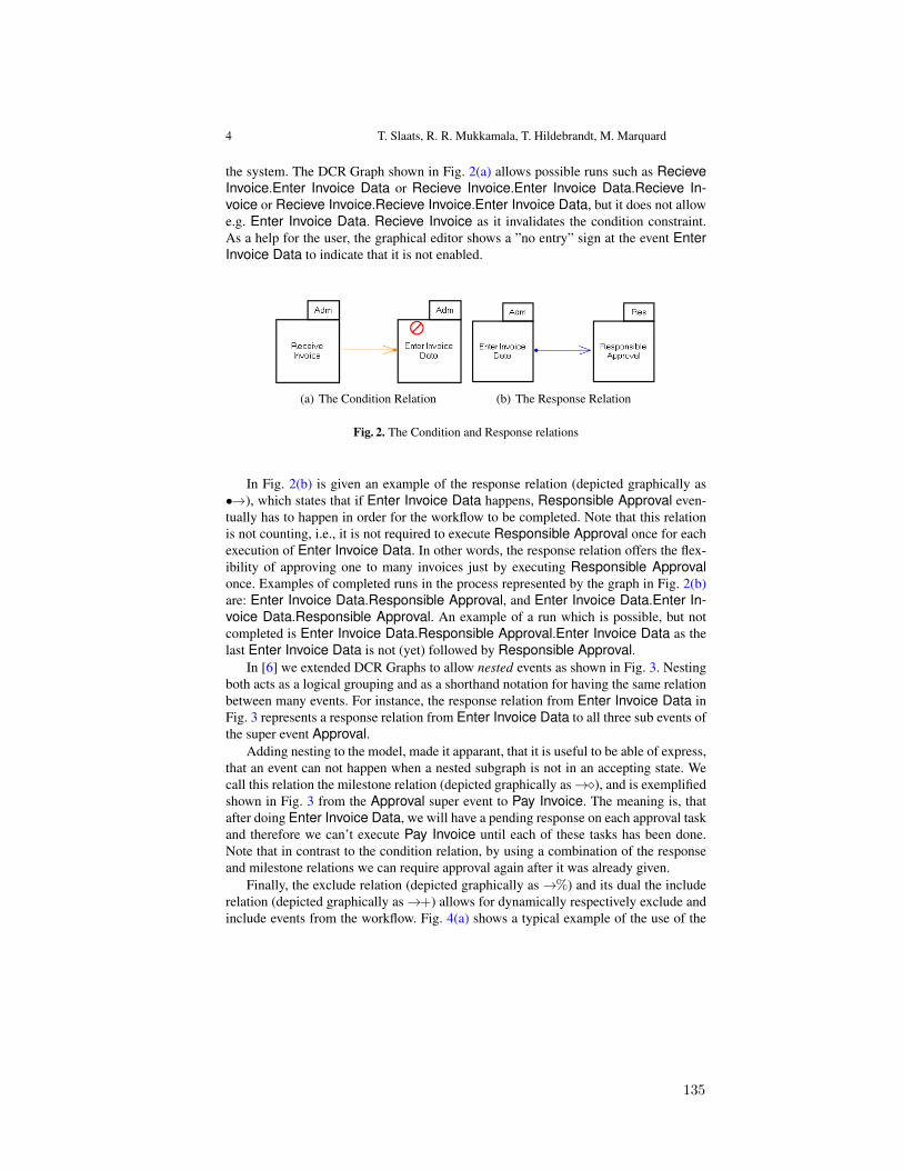
4 T. Slaats, R. R. Mukkamala, T. Hildebrandt, M. Marquard
the system. The DCR Graph shown in Fig. 2(a) allows possible runs such as RecieveInvoice.Enter Invoice Data or Recieve Invoice.Enter Invoice Data.Recieve In-voice or Recieve Invoice.Recieve Invoice.Enter Invoice Data, but it does not allowe.g. Enter Invoice Data. Recieve Invoice as it invalidates the condition constraint.As a help for the user, the graphical editor shows a ”no entry” sign at the event EnterInvoice Data to indicate that it is not enabled.
(a) The Condition Relation (b) The Response Relation
Fig. 2. The Condition and Response relations
In Fig. 2(b) is given an example of the response relation (depicted graphically as•!), which states that if Enter Invoice Data happens, Responsible Approval even-tually has to happen in order for the workflow to be completed. Note that this relationis not counting, i.e., it is not required to execute Responsible Approval once for eachexecution of Enter Invoice Data. In other words, the response relation offers the flex-ibility of approving one to many invoices just by executing Responsible Approvalonce. Examples of completed runs in the process represented by the graph in Fig. 2(b)are: Enter Invoice Data.Responsible Approval, and Enter Invoice Data.Enter In-voice Data.Responsible Approval. An example of a run which is possible, but notcompleted is Enter Invoice Data.Responsible Approval.Enter Invoice Data as thelast Enter Invoice Data is not (yet) followed by Responsible Approval.
In [6] we extended DCR Graphs to allow nested events as shown in Fig. 3. Nestingboth acts as a logical grouping and as a shorthand notation for having the same relationbetween many events. For instance, the response relation from Enter Invoice Data inFig. 3 represents a response relation from Enter Invoice Data to all three sub events ofthe super event Approval.
Adding nesting to the model, made it apparant, that it is useful to be able of express,that an event can not happen when a nested subgraph is not in an accepting state. Wecall this relation the milestone relation (depicted graphically as!⇧), and is exemplifiedshown in Fig. 3 from the Approval super event to Pay Invoice. The meaning is, thatafter doing Enter Invoice Data, we will have a pending response on each approval taskand therefore we can’t execute Pay Invoice until each of these tasks has been done.Note that in contrast to the condition relation, by using a combination of the responseand milestone relations we can require approval again after it was already given.
Finally, the exclude relation (depicted graphically as!%) and its dual the includerelation (depicted graphically as!+) allows for dynamically respectively exclude andinclude events from the workflow. Fig. 4(a) shows a typical example of the use of the
135
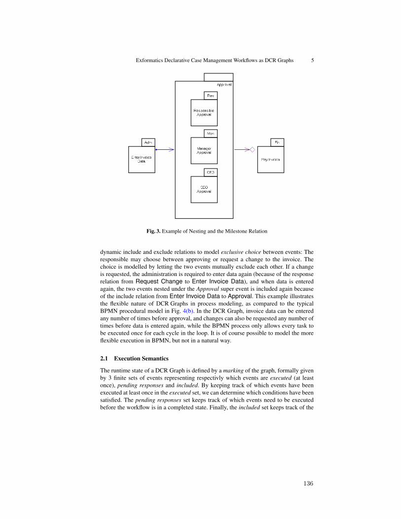
Exformatics Declarative Case Management Workflows as DCR Graphs 5
Fig. 3. Example of Nesting and the Milestone Relation
dynamic include and exclude relations to model exclusive choice between events: Theresponsible may choose between approving or request a change to the invoice. Thechoice is modelled by letting the two events mutually exclude each other. If a changeis requested, the administration is required to enter data again (because of the responserelation from Request Change to Enter Invoice Data), and when data is enteredagain, the two events nested under the Approval super event is included again becauseof the include relation from Enter Invoice Data to Approval. This example illustratesthe flexible nature of DCR Graphs in process modeling, as compared to the typicalBPMN procedural model in Fig. 4(b). In the DCR Graph, invoice data can be enteredany number of times before approval, and changes can also be requested any number oftimes before data is entered again, while the BPMN process only allows every task tobe executed once for each cycle in the loop. It is of course possible to model the moreflexible execution in BPMN, but not in a natural way.
2.1 Execution Semantics
The runtime state of a DCR Graph is defined by a marking of the graph, formally givenby 3 finite sets of events representing respectivly which events are executed (at leastonce), pending responses and included. By keeping track of which events have beenexecuted at least once in the executed set, we can determine which conditions have beensatisfied. The pending responses set keeps track of which events need to be executedbefore the workflow is in a completed state. Finally, the included set keeps track of the
136
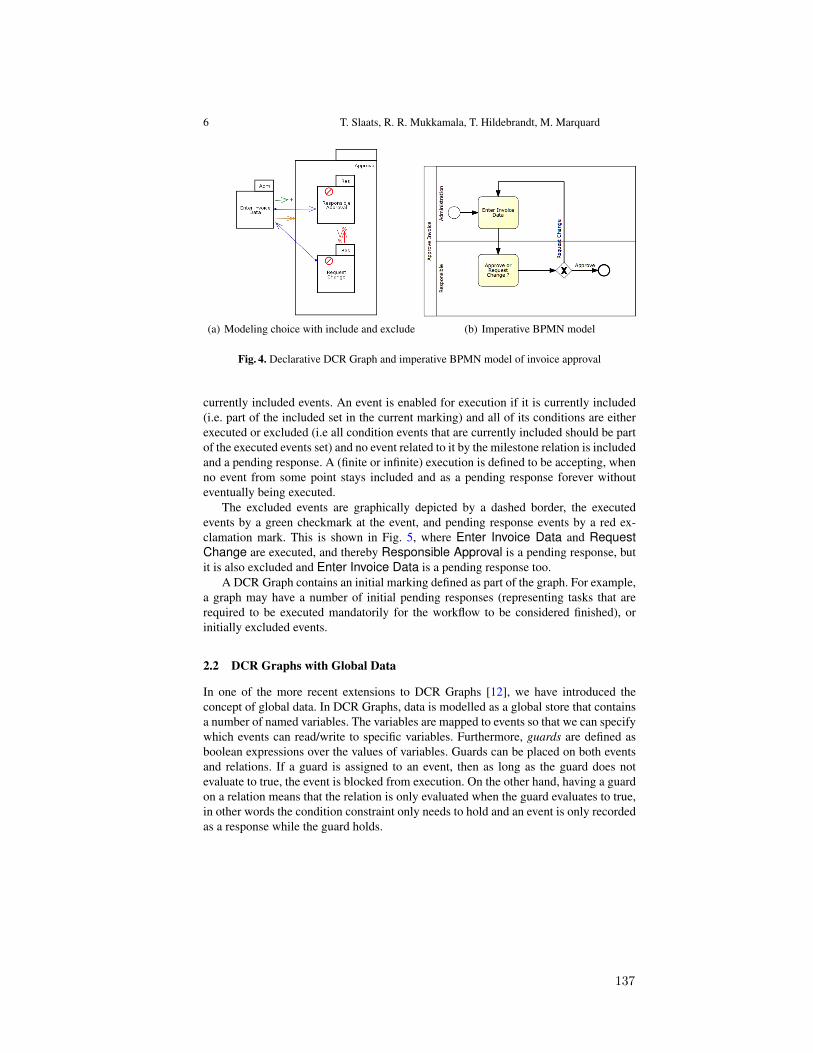
6 T. Slaats, R. R. Mukkamala, T. Hildebrandt, M. Marquard
(a) Modeling choice with include and exclude (b) Imperative BPMN model
Fig. 4. Declarative DCR Graph and imperative BPMN model of invoice approval
currently included events. An event is enabled for execution if it is currently included(i.e. part of the included set in the current marking) and all of its conditions are eitherexecuted or excluded (i.e all condition events that are currently included should be partof the executed events set) and no event related to it by the milestone relation is includedand a pending response. A (finite or infinite) execution is defined to be accepting, whenno event from some point stays included and as a pending response forever withouteventually being executed.
The excluded events are graphically depicted by a dashed border, the executedevents by a green checkmark at the event, and pending response events by a red ex-clamation mark. This is shown in Fig. 5, where Enter Invoice Data and RequestChange are executed, and thereby Responsible Approval is a pending response, butit is also excluded and Enter Invoice Data is a pending response too.
A DCR Graph contains an initial marking defined as part of the graph. For example,a graph may have a number of initial pending responses (representing tasks that arerequired to be executed mandatorily for the workflow to be considered finished), orinitially excluded events.
2.2 DCR Graphs with Global Data
In one of the more recent extensions to DCR Graphs [12], we have introduced theconcept of global data. In DCR Graphs, data is modelled as a global store that containsa number of named variables. The variables are mapped to events so that we can specifywhich events can read/write to specific variables. Furthermore, guards are defined asboolean expressions over the values of variables. Guards can be placed on both eventsand relations. If a guard is assigned to an event, then as long as the guard does notevaluate to true, the event is blocked from execution. On the other hand, having a guardon a relation means that the relation is only evaluated when the guard evaluates to true,in other words the condition constraint only needs to hold and an event is only recordedas a response while the guard holds.
137

Exformatics Declarative Case Management Workflows as DCR Graphs 7
Fig. 5. Example marking after executing Enter Invoice Data followed by Request Change
For example, the response between Enter Invoice Data and Manager Approvalin Fig 6 is only recorded when the amount of the invoice is equal or larger than 1000euro, if the amount is lower than 1000 euros, executing Enter Invoice Data will notmake Manager Approval a pending response.
3 Exformatics Workflows as DCR Graphs
Before the introduction of (Nested) DCR Graphs, the Exformatics workflow modelconsisted of tasks grouped under phases. There was always one active phase, whichcould be changed manually by the user, tasks belonging to that phase were then enabled.When introducing DCR Graphs we chose to map tasks to events and to maintain thephase model, mapping it to a single-level nesting structure. We removed the practicethat tasks were enabled when their phase was active and allowed the active phase tobe changed automatically through the execution of certain tasks. In the new model, theactive phase no longer controls the workflow but instead just gives a general indicationof the state that the case is in. We introduced all five relations of DCR Graphs as ways ofconstraining the flow of tasks. One distinction from the traditional DCR Graph approachis that tasks in the Exformatics system are normally only done once. As a result, whena task is executed, it is not shown in the list of tasks that need to be done anymore.However, unless it is exlicitely excluded through the exclude relation it remains possibleto open the task again manually and do it again, so the execution semantics remainsfaithful to the DCR Graphs semantics.
138
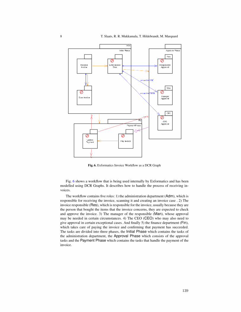
8 T. Slaats, R. R. Mukkamala, T. Hildebrandt, M. Marquard
Fig. 6. Exformatics Invoice Workflow as a DCR Graph
Fig. 6 shows a workflow that is being used internally by Exformatics and has beenmodelled using DCR Graphs. It describes how to handle the process of receiving in-voices.
The workflow contains five roles: 1) the administration department (Adm), which isresponsible for receiving the invoice, scanning it and creating an invoice case . 2) Theinvoice responsible (Res), which is responsible for the invoice, usually because they arethe person that bought the items that the invoice concerns, they are expected to checkand approve the invoice. 3) The manager of the responsible (Man), whose approvalmay be needed in certain circumstances. 4) The CEO (CEO) who may also need togive approval in certain exceptional cases. And finally 5) the finance department (Fin),which takes care of paying the invoice and confirming that payment has succeeded.The tasks are divided into three phases, the Initial Phase which contains the tasks ofthe administration department, the Approval Phase which consists of the approvaltasks and the Payment Phase which contains the tasks that handle the payment of theinvoice.
139

Exformatics Declarative Case Management Workflows as DCR Graphs 9
The process starts when an invoice is received by the administration department,because Exformatics wants to keep all their documents in an electronic format it is re-quired (through the response relation from Receive Invoice to Scan Invoice) that theinvoice is scanned. The administration department is also required to decide if the in-voice should be entered into the system (sometimes fake or wrong invoices are receivedwhich can be easily filtered out at first sight, for example because they are addressed toa non-existent employee). If they decide that the invoice appears legit then they enter allrelevant data into the system, in particular the amount the invoice is for, which is usedby the workflow system to determine whose approval is needed for the invoice. The re-sponsible for the invoice should always approve the invoice (modelled by an unguardedresponse relation), if the amount of the invoice is higher then 1000 euros, approval fromthe responsible’s manager is required as well (modelled by a response relation with theguard amount � 1000). In special cases where the amount is higher then 20000 euros,approval from the CEO of the company is required as well.
It is possible that data is entered again, for example because a mistake was madeby the administration department, or because a correction on the invoice was received,in this case new approvals will be required. When all necessary approvals have beenreceived the invoice can be paid, this is modelled through the milestone relation fromthe Approval Phase to the task Pay Invoice, which means that Pay Invoice can notbe done while there are pending responses in the Approval Phase. Once payment isconfirmed, the invoice case should be closed, modelled through an exclusion relationfrom Confirm Payment to all three phases. There are five conditions in the workflow:first of all, Receive Invoice is required before the administration department can exe-cute Enter Invoice Data or Scan Invoice. Enter Invoice Data is required before anyapproval can be given and all of the tasks in the Initial Phase should be done beforeany of the tasks in the Payment Phase can be done. Finaly, we have to pay the invoicebefore we can confirm payment.
4 Tool support
Several tools have been developed at Exformatics to design and execute DCR Graphsinternally or externally when presenting DCR Graphs at seminars or when interactingwith customers. First of all, to facilitate the exchange of process descriptions betweenthe tools developed by Exformatics and the tools being developed at IT University ofCopenhagen, we defined a common XML format, which we will show in the first sub-section. Secondly we developed a set of webservices that provide functionality for theexecution, verification, storage and visualization of DCR Graphs, we named this set ofservices the Process Engine. Finally, as already mentioned above, we developed a stand-alone graphical editor to support the visual modelling and simulation of DCR Graphs,called the DCR Graphs Editor, which has also been used for teaching at a bachelor levelcourse on Business Processes and IT at the IT University of Copenhagen.
Fig. 7 gives an overview of these tools and how they interact with eachother andthe Exformatics ECM. The Process Engine is central to our tools and is used by theECM to execute, verify and visualize workflows. The DCR Graphs Editor allows forexecution of single steps by itself, but also uses the Process Engine for verification
140

10 T. Slaats, R. R. Mukkamala, T. Hildebrandt, M. Marquard
Process Enginehttp://processengine.exformatics.net
Execution Repository
Visualization Verification
Other Applications at Customer
Exformatics ECM
DCR GraphsXML Format
DCR GraphsXML Format
DCR GraphsXML Format
DCR Graphs Editor
Fig. 7. Overview of the Exformatics DCR Graphs Tools
of DCR Graphs. Finally the purpose of the Process Engine is to be easily plugged into other case management solutions as well, so that we may provide only workflowfunctionalities such as execution, verification, visualization and storage to customerswithout them being required to adopt the full Exformatics ECM package.
4.1 DCR Graphs XML Format
In listing 1 we give an example of the XML format for describing DCR Graphs.The xml file consists of two main parts: the specification of the DCR Graph and the
runtime state of the DCR Graph. The specification is split up into a section decribingresources and section describing constraints. The resource section contains subsectionsfor events (possibly nested), labels, a mapping from labels to events, variables, expres-sions and variable acccess rights. The constraint section contains five subsections forthe DCR Graph relations. The runtime section contains a subsection for the marking,containing the set of executed events, pending responses and included events, and asubsection for the state of the globalstore, which contains the values assigned to thevariables in the current state.
Listing 1. Overview of DCR Graph XML Format<? xml v e r s i o n = ” 1 . 0 ” e n c o d i n g = ” u t f 8 ” ?><d c r g r a p h>
<s p e c i f i c a t i o n><r e s o u r c e s>
<e v e n t s><e v e n t i d =” I n i t i a l Phase ”>
<e v e n t i d =” E n t e r I n v o i c e Data ” />. . .
</ e v e n t>
141

Exformatics Declarative Case Management Workflows as DCR Graphs 11
. . .</ e v e n t s>< l a b e l s>
<l a b e l i d =”CEO Approva l ” />. . .
</ l a b e l s><l a b e l M a p p i n g s>
<l a b e l M a p p i n g e v e n t I d =”CEO Approva l ” l a b e l I d =”CEO Approva l ” />. . .
</ l a b e l M a p p i n g s><v a r i a b l e s>
<v a r i a b l e i d =” amount ” v a l u e =” 0 ” /></ v a r i a b l e s><e x p r e s s i o n s>
<e x p r e s s i o n i d =” g te1000 ” v a l u e =” amount >= 1000 ” />. . .
</ e x p r e s s i o n s><v a r i a b l e A c c e s s e s>
<r e a d A c c e s s e s><r e a d A c c e s s e v e n t I d =” E n t e r I n v o i c e Data ” v a r i a b l e I d =” amount ” />. . .
</ r e a d A c c e s s e s><w r i t e A c c e s s e s>
<w r i t e A c c e s s e v e n t I d =” E n t e r I n v o i c e Data ” v a r i a b l e I d =” amount ” /></ w r i t e A c c e s s e s>
</ v a r i a b l e A c c e s s e s></ r e s o u r c e s><c o n s t r a i n t s>
<c o n d i t i o n s><c o n d i t i o n s o u r c e I d =” Rece ive I n v o i c e ” t a r g e t I d =” Scan I n v o i c e ” />. . .
</ c o n d i t i o n s><r e s p o n s e s>
<r e s p o n s e s o u r c e I d =” E n t e r I n v o i c e Data ” t a r g e t I d =” Manager Approva l ”e x p r e s s i o n I d =” g te1000 ” />
. . .</ r e s p o n s e s><e x c l u d e s>
<e x c l u d e s o u r c e I d =” Confirm Payment ” t a r g e t I d =” Approva l Phase ” />. . .
</ e x c l u d e s><i n c l u d e s /><m i l e s t o n e s>
<m i l e s t o n e s o u r c e I d =” Approva l Phase ” t a r g e t I d =” Pay I n v o i c e ” /></ m i l e s t o n e s>
</ c o n s t r a i n t s></ s p e c i f i c a t i o n><r u n t i m e>
<marking><e x e c u t e d /><i n c l u d e d>
<e v e n t i d =” Approva l Phase ” />. . .
</ i n c l u d e d><p e n d i n g R e s p o n s e s />
</ marking><g l o b a l S t o r e>
<v a r i a b l e i d =” amount ” v a l u e =” 0 ” /></ g l o b a l S t o r e>
</ r u n t i m e></ d c r g r a p h>
Next to the standard elements described above, it is possible to insert custom ele-ments at all nodes of the XML tree. This allows one to add additional data for specifictools that is not required for the formal definition of a DCR Graph. Examples of theseare the roles (they are not a part of the formal model as they are not necesairily interest-
142
12 T. Slaats, R. R. Mukkamala, T. Hildebrandt, M. Marquard
ing for applications in other domains than BPM) and the location of events when drawnin the visual editor as shown in listing 2.
Listing 2. Example of how custom data can be insterted into the XML format.<? xml v e r s i o n =” 1 . 0 ” e n c o d i n g =” u t f 8 ” ?><e v e n t i d =”CEO Approva l ”>
<custom><v i s u a l i z a t i o n>
<l o c a t i o n xLoc=” 449 ” yLoc=” 123 ” /></ v i s u a l i z a t i o n>
<r o l e s><r o l e>CEO</ r o l e>
</ r o l e s></ custom>
</ e v e n t>
4.2 Process Engine
Currently the Process Engine consists of three main webservices: the first for execution,the second for storage of DCR Graphs and the third for visualization of DCR Graphs.The execution service contains methods for executing and verifying DCR Graphs. Theexecution methods support the global data model, verification consists of checking fordeadlock and livelock, but only for standard DCR Graphs without data. In the futurewe plan to extend the verification aspect and move it to its own service. The repositoryservice for storage of DCR Graphs is currently very limited and mainly a proof ofconcept, it is planned to extend this in the future so it can be used to support sharingof workflows between cooperating organizations. The visualization service can be usedto automatically layout and draw DCR Graphs, currently limited to the basic modelwithout guards on data. All of these services are used by the Exformatics ECM formodelling and executing workflows.
4.3 DCR Graphs Editor
The DCR Graphs Editor is a graphical editor for modelling and simulating DCR Graphs.There are two main screens in the tool: in the Process Model screen one can design DCRGraphs by drawing events, changing the name, label and initial marking, adding rolesand adding relations between events. In he Process Simulation Screen one can simulateDCR Graphs by clicking on the events that one wants to execute, the tool will givefeedback on the current trace of executed events, which events can be executed and ifthe DCR Graph is in an accepting state. The tool can also interact with the verifica-tion methods of the Process Engine to check DCR Graphs for deadlock and livelock.It currently supports nested DCR Graphs including the milestone relation and work isunderway to also add support for the global data model. All the images of DCR Graphsin this paper come directly from the editor.
5 Related Work
As mentioned in the introduction Declare [15, 19] was the first serious attempt at cre-ating a declarative notation for describing business processes. Tool support for Declare
143
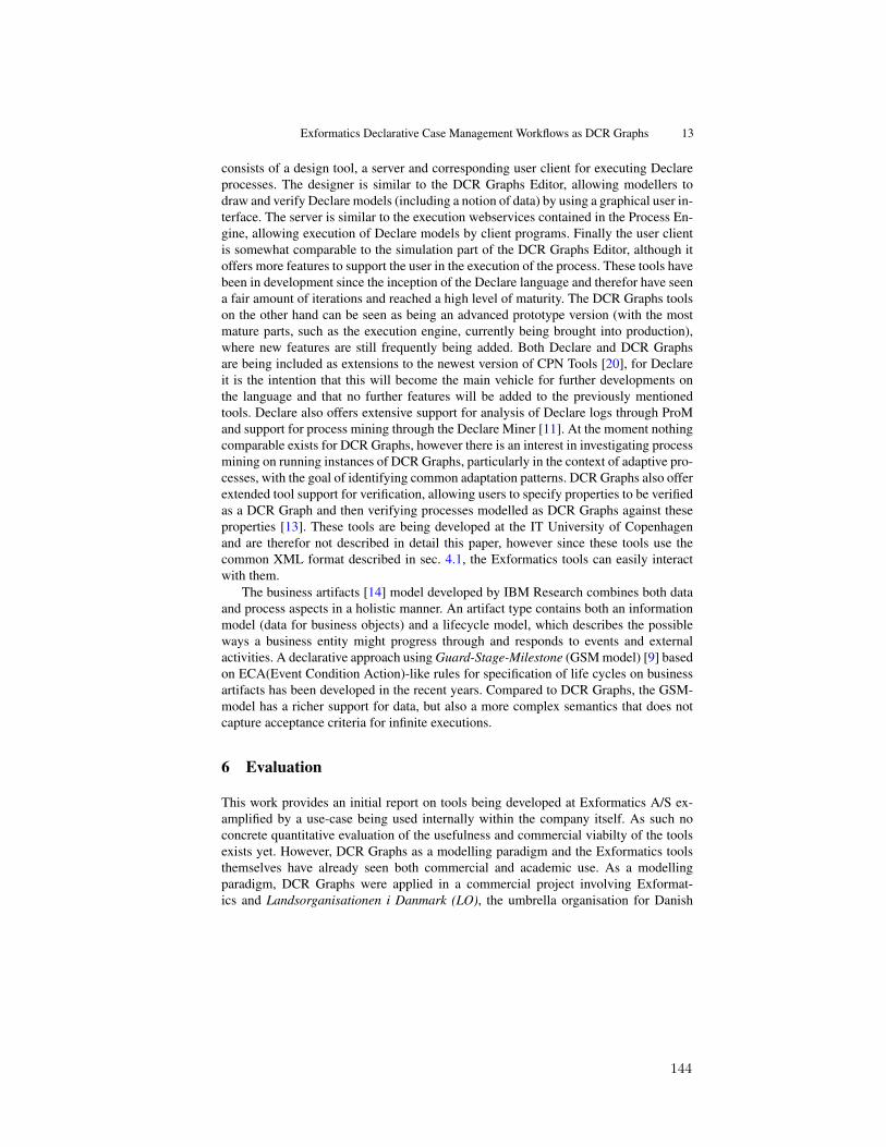
Exformatics Declarative Case Management Workflows as DCR Graphs 13
consists of a design tool, a server and corresponding user client for executing Declareprocesses. The designer is similar to the DCR Graphs Editor, allowing modellers todraw and verify Declare models (including a notion of data) by using a graphical user in-terface. The server is similar to the execution webservices contained in the Process En-gine, allowing execution of Declare models by client programs. Finally the user clientis somewhat comparable to the simulation part of the DCR Graphs Editor, although itoffers more features to support the user in the execution of the process. These tools havebeen in development since the inception of the Declare language and therefor have seena fair amount of iterations and reached a high level of maturity. The DCR Graphs toolson the other hand can be seen as being an advanced prototype version (with the mostmature parts, such as the execution engine, currently being brought into production),where new features are still frequently being added. Both Declare and DCR Graphsare being included as extensions to the newest version of CPN Tools [20], for Declareit is the intention that this will become the main vehicle for further developments onthe language and that no further features will be added to the previously mentionedtools. Declare also offers extensive support for analysis of Declare logs through ProMand support for process mining through the Declare Miner [11]. At the moment nothingcomparable exists for DCR Graphs, however there is an interest in investigating processmining on running instances of DCR Graphs, particularly in the context of adaptive pro-cesses, with the goal of identifying common adaptation patterns. DCR Graphs also offerextended tool support for verification, allowing users to specify properties to be verifiedas a DCR Graph and then verifying processes modelled as DCR Graphs against theseproperties [13]. These tools are being developed at the IT University of Copenhagenand are therefor not described in detail this paper, however since these tools use thecommon XML format described in sec. 4.1, the Exformatics tools can easily interactwith them.
The business artifacts [14] model developed by IBM Research combines both dataand process aspects in a holistic manner. An artifact type contains both an informationmodel (data for business objects) and a lifecycle model, which describes the possibleways a business entity might progress through and responds to events and externalactivities. A declarative approach using Guard-Stage-Milestone (GSM model) [9] basedon ECA(Event Condition Action)-like rules for specification of life cycles on businessartifacts has been developed in the recent years. Compared to DCR Graphs, the GSM-model has a richer support for data, but also a more complex semantics that does notcapture acceptance criteria for infinite executions.
6 Evaluation
This work provides an initial report on tools being developed at Exformatics A/S ex-amplified by a use-case being used internally within the company itself. As such noconcrete quantitative evaluation of the usefulness and commercial viabilty of the toolsexists yet. However, DCR Graphs as a modelling paradigm and the Exformatics toolsthemselves have already seen both commercial and academic use. As a modellingparadigm, DCR Graphs were applied in a commercial project involving Exformat-ics and Landsorganisationen i Danmark (LO), the umbrella organisation for Danish
144
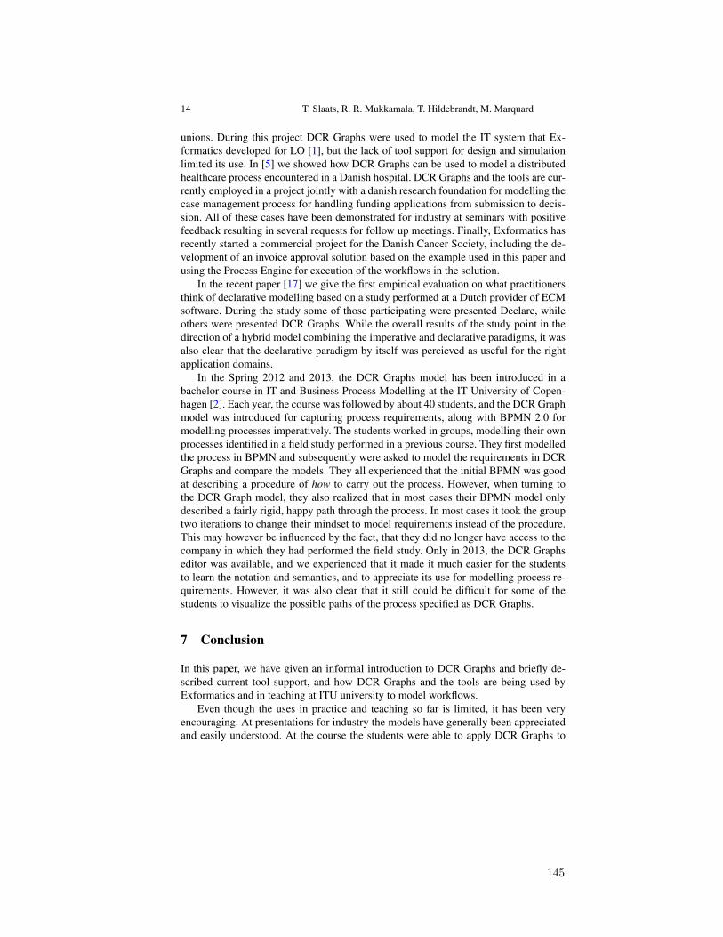
14 T. Slaats, R. R. Mukkamala, T. Hildebrandt, M. Marquard
unions. During this project DCR Graphs were used to model the IT system that Ex-formatics developed for LO [1], but the lack of tool support for design and simulationlimited its use. In [5] we showed how DCR Graphs can be used to model a distributedhealthcare process encountered in a Danish hospital. DCR Graphs and the tools are cur-rently employed in a project jointly with a danish research foundation for modelling thecase management process for handling funding applications from submission to decis-sion. All of these cases have been demonstrated for industry at seminars with positivefeedback resulting in several requests for follow up meetings. Finally, Exformatics hasrecently started a commercial project for the Danish Cancer Society, including the de-velopment of an invoice approval solution based on the example used in this paper andusing the Process Engine for execution of the workflows in the solution.
In the recent paper [17] we give the first empirical evaluation on what practitionersthink of declarative modelling based on a study performed at a Dutch provider of ECMsoftware. During the study some of those participating were presented Declare, whileothers were presented DCR Graphs. While the overall results of the study point in thedirection of a hybrid model combining the imperative and declarative paradigms, it wasalso clear that the declarative paradigm by itself was percieved as useful for the rightapplication domains.
In the Spring 2012 and 2013, the DCR Graphs model has been introduced in abachelor course in IT and Business Process Modelling at the IT University of Copen-hagen [2]. Each year, the course was followed by about 40 students, and the DCR Graphmodel was introduced for capturing process requirements, along with BPMN 2.0 formodelling processes imperatively. The students worked in groups, modelling their ownprocesses identified in a field study performed in a previous course. They first modelledthe process in BPMN and subsequently were asked to model the requirements in DCRGraphs and compare the models. They all experienced that the initial BPMN was goodat describing a procedure of how to carry out the process. However, when turning tothe DCR Graph model, they also realized that in most cases their BPMN model onlydescribed a fairly rigid, happy path through the process. In most cases it took the grouptwo iterations to change their mindset to model requirements instead of the procedure.This may however be influenced by the fact, that they did no longer have access to thecompany in which they had performed the field study. Only in 2013, the DCR Graphseditor was available, and we experienced that it made it much easier for the studentsto learn the notation and semantics, and to appreciate its use for modelling process re-quirements. However, it was also clear that it still could be difficult for some of thestudents to visualize the possible paths of the process specified as DCR Graphs.
7 Conclusion
In this paper, we have given an informal introduction to DCR Graphs and briefly de-scribed current tool support, and how DCR Graphs and the tools are being used byExformatics and in teaching at ITU university to model workflows.
Even though the uses in practice and teaching so far is limited, it has been veryencouraging. At presentations for industry the models have generally been appreciatedand easily understood. At the course the students were able to apply DCR Graphs to
145
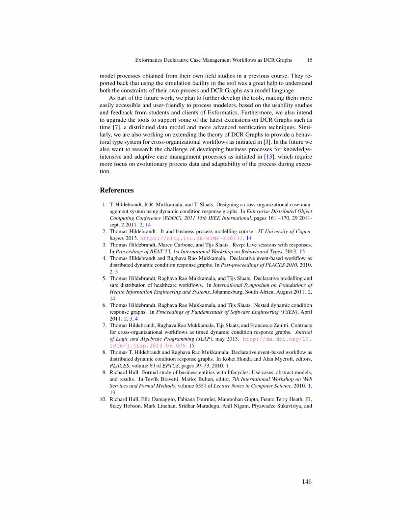
Exformatics Declarative Case Management Workflows as DCR Graphs 15
model processes obtained from their own field studies in a previous course. They re-ported back that using the simulation facility in the tool was a great help to understandboth the constraints of their own process and DCR Graphs as a model language.
As part of the future work, we plan to further develop the tools, making them moreeasily accessible and user-friendly to process modelers, based on the usability studiesand feedback from students and clients of Exformatics. Furthermore, we also intendto upgrade the tools to support some of the latest extensions on DCR Graphs such astime [7], a distributed data model and more advanced verification techniques. Simi-larly, we are also working on extending the theory of DCR Graphs to provide a behav-ioral type system for cross-organizational workflows as initiated in [3]. In the future wealso want to research the challenge of developing business processes for knowledge-intensive and adaptive case management processes as initiated in [13], which requiremore focus on evolutionary process data and adaptability of the process during execu-tion.
References
1. T. Hildebrandt, R.R. Mukkamala, and T. Slaats. Designing a cross-organizational case man-agement system using dynamic condition response graphs. In Enterprise Distributed ObjectComputing Conference (EDOC), 2011 15th IEEE International, pages 161 –170, 29 2011-sept. 2 2011. 2, 14
2. Thomas Hildebrandt. It and business process modelling course. IT University of Copen-hagen, 2013. https://blog.itu.dk/BIMF-F2013/. 14
3. Thomas Hildebrandt, Marco Carbone, and Tijs Slaats. Rsvp: Live sessions with responses.In Proceedings of BEAT’13, 1st International Workshop on Behavioural Types, 2013. 15
4. Thomas Hildebrandt and Raghava Rao Mukkamala. Declarative event-based workflow asdistributed dynamic condition response graphs. In Post-proceedings of PLACES 2010, 2010.2, 3
5. Thomas Hildebrandt, Raghava Rao Mukkamala, and Tijs Slaats. Declarative modelling andsafe distribution of healthcare workflows. In International Symposium on Foundations ofHealth Information Engineering and Systems, Johannesburg, South Africa, August 2011. 2,14
6. Thomas Hildebrandt, Raghava Rao Mukkamala, and Tijs Slaats. Nested dynamic conditionresponse graphs. In Proceedings of Fundamentals of Software Engineering (FSEN), April2011. 2, 3, 4
7. Thomas Hildebrandt, Raghava Rao Mukkamala, Tijs Slaats, and Francesco Zanitti. Contractsfor cross-organizational workflows as timed dynamic condition response graphs. Journalof Logic and Algebraic Programming (JLAP), may 2013. http://dx.doi.org/10.1016/j.jlap.2013.05.005. 15
8. Thomas T. Hildebrandt and Raghava Rao Mukkamala. Declarative event-based workflow asdistributed dynamic condition response graphs. In Kohei Honda and Alan Mycroft, editors,PLACES, volume 69 of EPTCS, pages 59–73, 2010. 1
9. Richard Hull. Formal study of business entities with lifecycles: Use cases, abstract models,and results. In Tevfik Bravetti, Mario; Bultan, editor, 7th International Workshop on WebServices and Formal Methods, volume 6551 of Lecture Notes in Computer Science, 2010. 1,13
10. Richard Hull, Elio Damaggio, Fabiana Fournier, Manmohan Gupta, Fenno Terry Heath, III,Stacy Hobson, Mark Linehan, Sridhar Maradugu, Anil Nigam, Piyawadee Sukaviriya, and
146
16 T. Slaats, R. R. Mukkamala, T. Hildebrandt, M. Marquard
Roman Vaculin. Introducing the guard-stage-milestone approach for specifying businessentity lifecycles. In Proc. of WS-FM’10, pages 1–24, Berlin, Heidelberg, 2011. Springer-Verlag. 2
11. F.M. Maggi, A.J. Mooij, and W.M.P. van der Aalst. User-Guided Discovery of DeclarativeProcess Models. In 2011 IEEE Symposium on Computational Intelligence and Data Mining.IEEE, 2011. 13
12. Raghava Rao Mukkamala. A Formal Model For Declarative Workflows - Dynamic ConditionResponse Graphs. PhD thesis, IT University of Copenhagen, March 2012. Forthcomming.3, 6
13. Raghava Rao Mukkamala, Thomas Hildebrandt, and Tijs Slaats. Towards trustworthy adap-tive case management with dynamic condition response graphs. In Proceedings of the 17thIEEE International EDOC Conference, EDOC 2013, 2013. 13, 15
14. A. Nigam and N. S. Caswell. Business artifacts: An approach to operational specification.IBM Syst. J., 42:428–445, July 2003. 13
15. M. Pesic, M. H. Schonenberg, N. Sidorova, and W. M. P. Van Der Aalst. Constraint-basedworkflow models: change made easy. In Proceedings of the 2007 OTM Confederated interna-tional conference on On the move to meaningful internet systems: CoopIS, DOA, ODBASE,GADA, and IS - Volume Part I, OTM’07, pages 77–94, Berlin, Heidelberg, 2007. Springer-Verlag. 1, 2, 12
16. M. Pesic and W. M. P. van der Aalst. A declarative approach for flexible business processesmanagement. In Proc. of the 2006 international conference on Business Process Manage-ment Workshops, BPM’06, pages 169–180. Springer-Verlag, 2006. 1, 2
17. Hajo A. Reijers, Tijs Slaats, and Christian Stahl. Declarative Modeling—An AcademicDream or the Future for BPM? . Accepted for BPM 2013. 14
18. Tijs Slaats. Dcr graphs wiki. IT University of Copenhagen, 2013. http://www.itu.dk/research/models/wiki/index.php/DCR_Graphs_Editor. 2, 3
19. W. M. P. van der Aalst, M. Pesic, and H. Schonenberg. Declarative workflows: Balancingbetween flexibility and support. Computer Science - R&D, 23(2):99–113, 2009. 1, 2, 12
20. M. Westergaard and T. Slaats. Mixing Paradigms for More Comprehensible Models. Ac-cepted for BPM 2013. 13
21. Glynn Winskel. Events in Computation. PhD thesis, Edinburgh University, 1980. 2
147

6 Safe Cross-Organizational Flexible Processes
148

Safe Distribution of Declarative Processes
Thomas Hildebrandt1, Raghava Rao Mukkamala1, and Tijs Slaats1,2 ?
1 IT University of CopenhagenRued Langgaardsvej 7, 2300 Copenhagen, Denmark{hilde, rao, tslaats}@itu.dk, http://www.itu.dk
2 Exformatics A/S, 2100 Copenhagen, Denmark
Abstract. We give a general technique for safe distribution of a declarative (global)process as a network of (local) synchronously communicating declarative pro-cesses. Both the global and local processes are given as Dynamic Condition Re-sponse (DCR) Graphs. DCR Graphs is a recently introduced declarative processmodel generalizing labelled prime event structures to a systems model able tofinitely represent ω-regular languages. An operational semantics given as a tran-sition semantics between markings of the graph allows DCR Graphs to be conve-niently used as both specification and execution model. The technique for distri-bution is based on a new general notion of projection of DCR Graphs relative to asubset of labels and events identifying the set of external events that must be com-municated from the other processes in the network in order for the distribution tobe safe. We prove that for any vector of projections that covers a DCR Graph thatthe network of synchronously communicating DCR Graphs given by the projec-tions is bisimilar to the original global process graph. We exemplify the distribu-tion technique on a process identified in a case study of an cross-organizationalcase management system carried out jointly with Exformatics A/S.
1 Introduction
A model-driven software engineering approach to distributed information systems typi-cally include both global models describing the collective behavior of the system beingdeveloped and local models describing the behavior of the individual peers or compo-nents.
The global and local descriptions should be consistent. If the modeling languageshave formal semantics and the local model language support composition of individualprocesses, the consistency can be formally established, which we will refer to as theconsistency problem: Given a global model and a set of local models, is the behavior ofthe composition of the local models consistent with the global model? In order to sup-port ”top-down” model-driven engineering starting from the global model, one shouldaddress the more challenging distributed synthesis problem: Given a global model and
? Authors listed alphabetically. This research is supported by the Danish ResearchAgency through a Knowledge Voucher granted to Exformatics (grant #10-087067,www.exformatics.com), the Trustworthy Pervasive Healthcare Services project (grant #2106-07-0019, www.trustcare.eu) and the Computer Supported Mobile Adaptive Business Processesproject (grant #274-06-0415, www.cosmobiz.dk).
149
2 Hildebrandt, Mukkamala, Slaats
some formal description of how the model should be distributed, can we synthesize aset of local processes with respect to this distribution which are consistent to the theglobal model?
In past work, briefly surveyed below, the result of the distributed synthesis have beena network of local processes described in an imperative process model, e.g. as a networkof typed pi-calculus processes or a product automaton. The global process descriptionhas either been given declaratively, e.g. in some temporal logic, or imperatively, e.g. asa choreography or more generally a transition system.
In the present paper we address the distributed synthesis problem in a setting whereboth the global and the local processes are described declaratively as Dynamic Con-dition Response Graphs (DCR Graphs). DCR Graphs is a declarative workflow modelintroduced previously in [14, 15] as a generalization of the classical event structuremodel [47] allowing finite specification of infinite behavior (by allowing events to beexecuted more than once and replacing the symmetric conflict relation by asymmet-ric exclusion and (re-)inclusion relations) and specification of progress conditions (byreplacing the causal order relation of event structures with two relations, respectivelydefining the conditions for and required responses to the execution of an event).
The motivation for introducing the DCR Graph model is to give, as part of theTrustworthy Pervasive Healthcare Services [13] project, a declarative model that can beused both as specification language and execution language for flexible workflow andbusiness process. Indeed, the DCR Graphs model is inspired by and formalizes the coreprimitives of the process model employed by the industrial partner (Resultmaker) in theTrustCare project and is now being implemented in the workflow engine developed atExformatics. As identified in e.g. [6,43] declarative process languages make it easier tospecify loosely constrained systems. Also, we believe the declarative approach is morepromising when it comes to composition, and (dynamic) changes of processes which isone of the main objectives of the TrustCare project.
To safely distribute a DCR Graph we first define (Def. 3, Sec. 3.1) a new generalnotion of projection of DCR Graphs relative to a subset of labels and events. The keypoint is to identify the set of events that must be communicated from other processesin the network in order for the state of the local process to stay consistent with theglobal specification (Prop. 1, Sec. 3). To also enable the reverse operation, buildingglobal graphs from local graphs, we then define the composition of two DCR Graphs,essentially by gluing joint events. As a sanity check we prove (Prop. 2, Sec. 3.2) that ifwe have a collection of projections of a DCR Graph that cover the original graph (Def. 7,Sec. 3.2) then the composition yields back the same graph. We then finally proceed tothe main technical result, defining networks of synchronously communicating DCRGraphs and stating (in Thm. 1, Sec. 3.3) the correspondence between a global processand a network of communicating DCR Graphs obtained from a covering projection(relying on Prop. 1). Throughout the paper we exemplify the distribution technique ona simple cross-organizational process identified within a case study carried out jointlywith Exformatics A/S using DCR Graphs for model-driven design and engineering ofan inter-organizational case management system. We conclude in Sec. 4 and providepointers to future work.
150
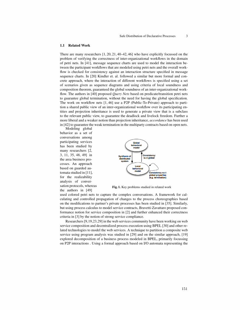
Safe Distribution of Declarative Processes 3
1.1 Related Work
There are many researchers [1, 20, 21, 40–42, 46] who have explicitly focussed on theproblem of verifying the correctness of inter-organizational workflows in the domainof petri nets. In [41], message sequence charts are used to model the interaction be-tween the participant workflows that are modeled using petri nets and the overall work-flow is checked for consistency against an interaction structure specified in messagesequence charts. In [20] Kindler et. al. followed a similar but more formal and con-crete approach, where the interaction of different workflows is specified using a setof scenarios given as sequence diagrams and using criteria of local soundness andcomposition theorem, guaranteed the global soundness of an inter-organizational work-flow. The authors in [40] proposed Query Nets based on predicate/transition petri netsto guarantee global termination, without the need for having the global specification.The work on workflow nets [1, 46] use a P2P (Public-To-Private) approach to parti-tion a shared public view of an inter-organizational workflow over its participating en-tities and projection inheritance is used to generate a private view that is a subclassto the relevant public view, to guarantee the deadlock and livelock freedom. Further amore liberal and a weaker notion than projection inheritance, accordance has been usedin [42] to guarantee the weak termination in the multiparty contracts based on open nets.
Fig. 1. Key problems studied in related work
Modeling globalbehavior as a set ofconversations amongparticipating serviceshas been studied bymany researchers [2,3, 11, 35, 48, 49] inthe area business pro-cesses. An approachbased on guarded au-tomata studied in [11],for the realizabilityanalysis of conver-sation protocols, whereasthe authors in [49]used colored petri nets to capture the complex conversations. A framework for cal-culating and controlled propagation of changes to the process choreographies basedon the modifications to partner’s private processes has been studied in [35]. Similarly,but using process calculus to model service contracts, Bravetti-Zavattaro proposed con-formance notion for service composition in [2] and further enhanced their correctnesscriteria in [3] by the notion of strong service compliance.
Researchers [9,19,23,29] in the web services community have been working on webservice composition and decentralized process execution using BPEL [30] and other re-lated technologies to model the web services. A technique to partition a composite webservice using program analysis was studied in [29] and on the similar approach, [19]explored decomposition of a business process modeled in BPEL, primarily focussingon P2P interactions . Using a formal approach based on I/O automata representing the
151

4 Hildebrandt, Mukkamala, Slaats
services, the authors in [23] have studied the problem of synthesizing a decentralizedchoreography strategy, that will have optimal overhead of service composition in termsof costs associated with each interaction.
The derivation of descriptions of local components from a global model has beenresearched for the imperative choreography language WS-CDL in the work on struc-tured communication-centred programming for web services by Carbone, Honda andYoshida [4]. To put it briefly, the work formalizes the core of WS-CDL as the globalprocess calculus and defines a formal theory of end-point projections projecting theglobal process calculus to abstract descriptions of the behavior of each of the local”end-points” given as pi-calculus processes typed with session types.
A methodology for deriving process descriptions from a business contract formal-ized in a formal contract language was studied in [22], while [36] proposes an approachto extract a distributed process model from collaborative business process. In [9, 10],the authors have proposed a technique for the flexible decentralization of a processspecification with necessary synchronization between the processing entities using de-pendency tables.
In [5, 12, 27] foundational work has been made on synthesizing distributed transi-tion systems from global specification for the models of synchronous product and asyn-chronous automata [50]. In [27] Mukund categorized structural and behavioral charac-terizations of the synthesis problem for synchronous and loosely cooperating commu-nication systems based on three different notions of equivalence: state space, languageand bisimulation equivalence. Further Castellani et. al. [5] characterized when an an ar-bitrary transition system is isomorphic to its product transition systems with a specifieddistribution of actions and they have shown that for finite state specifications, a finitestate distributed implementation can be synthesized. Complexity results for distributedsynthesis problems for the three notions of equivalences were studied in [12].
Many commercial and research workflow management systems also support dis-tributed workflow execution and some of them even support ad-hoc changes as well.ADEPT [34], Exotica [24], ORBWork [7], Rainman [31] and Newcastle-Nortel [39]are some of the distributed workflow management systems. A good overview and dis-cussion about distributed workflow management systems can be found in [32, 33].
So far the formalisms discussed above are more or less confined to imperative mod-eling languages such as Petri nets, workflow/open nets and automata based languages.To the best of our knowledge, there exists very few works [8, 25] that have studied thesynthesis problem in declarative modeling languages and none where both the globaland local processes are given declaratively. In [8], Fahland has studied synthesizingdeclarative workflows expressed in DecSerFlow [45] by translating to Petri nets. Onlya predefined set of DecSerFlow constraints are used in the mapping to the Petri netspatterns, so this approach has a limitation with regards to the extensibility of the Dec-SerFlow language. On the other hand, in [25] Montali has studied the composition ofConDec [44] models with respect to conformance with a given choreography, based onthe compatibility of the local ConDec models. But his study was limited to only com-position, whereas the problem of synthesizing local models from a global model hasnot been studied.
152

Safe Distribution of Declarative Processes 5
2 Dynamic Condition Response Graphs
Dynamic Condition Response (DCR) Graphs has recently been introduced [15] as adeclarative process model generalizing labelled event structures [47] to allow finite rep-resentations of infinite behavior (i.e. a systems model [37, 38]) and representation ofprogress properties.
A DCR Graph consists of a set of labelled events, a marking defining the executedevents, pending response events and included events, and four binary relations betweenthe events, defining the temporal constraints between events and dynamic inclusion andexclusion of events.
We employ the following notations in the rest of the paper.Notation: For a set A we write P(A) for the power set of A. For a binary relation→⊆ A × A and a subset ξ ⊆ A of A we write → ξ and ξ → for the set {a ∈ A |(∃a′ ∈ ξ | a → a′)} and the set {a ∈ A | (∃a′ ∈ ξ | a′ → a)} respectively. Also, wewrite→−1 for the inverse relation. Finally, for a natural number k we write [k] for theset {1, 2, . . . , k}.
We then formally define a DCR Graph as follows.
Definition 1. A Dynamic Condition Response Graph G is a tuple (EG,MG,→•, •→,±, LG, lG), where
(i) EG is the set of events(ii) MG = (ExG,ReG, InG) ∈ P(EG)× P(EG)× P(EG) is the marking,
(iii) →•⊆ EG × EG is the condition relation(iv) •→⊆ EG × EG is the response relation(v) ± : EG × EG ⇀ {+,%} is a partial function defining the dynamic inclusion and
exclusion relations by e→+ e′ if ±(e, e′) = + and e→% e′ if ±(e, e′) = %(vi) LG is the set of labels
(vii) lG : EG → P(LG) is a labeling function mapping events to sets of labels.
We writeM(G) for the set P(EG)× P(EG)× P(EG) of markings of G.
The marking MG = (ExG,ReG, InG) is a tuple of three sets defining respectively thepreviously executed events (ExG), the set of required responses (ReG), and the currentlyincluded events (InG). The set of required responses are the events that must eventu-ally be executed (or excluded) in order to accept the execution, also referred to as thepending responses. The set of included events are the events that currently are relevantfor conditions and may be executed (if their conditions are met). The condition relation→• defines which (of the currently included) events must have been executed before anevent can be executed. That is, for an event e to be executed, it must be included, i.e.e ∈ InG and the included conditions must be executed: (→• e) ∩ InG ⊆ ExG. The re-sponse relation •→ defines which responses are required after executing an event. Thatis, if the event e is executed, the events e •→ are added to the set of required responsesin the marking. The dynamic inclusion and exclusion relations define how the set ofincluded events changes by executing an event: If the event e is executed, the eventse →+ are added to the set of included events in the marking and the events e →%are removed. Finally, an event is labelled by zero or more labels. (This is slightly more
153
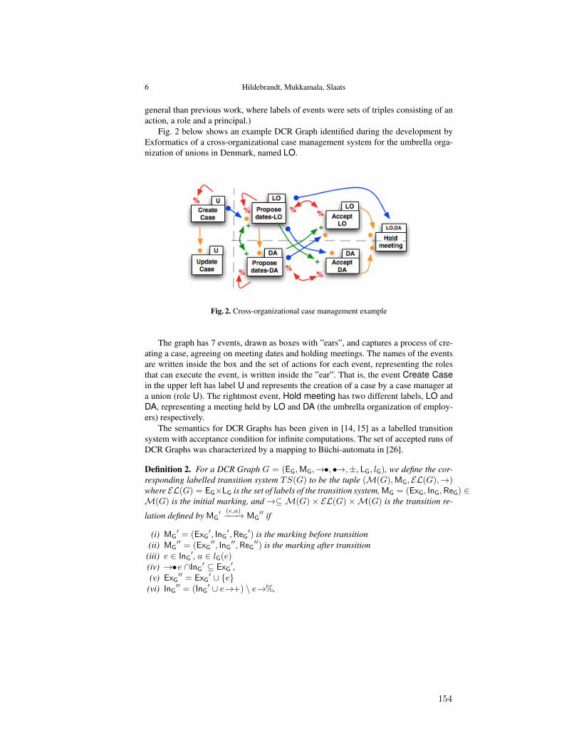
6 Hildebrandt, Mukkamala, Slaats
general than previous work, where labels of events were sets of triples consisting of anaction, a role and a principal.)
Fig. 2 below shows an example DCR Graph identified during the development byExformatics of a cross-organizational case management system for the umbrella orga-nization of unions in Denmark, named LO.
Fig. 2. Cross-organizational case management example
The graph has 7 events, drawn as boxes with ”ears”, and captures a process of cre-ating a case, agreeing on meeting dates and holding meetings. The names of the eventsare written inside the box and the set of actions for each event, representing the rolesthat can execute the event, is written inside the ”ear”. That is, the event Create Casein the upper left has label U and represents the creation of a case by a case manager ata union (role U). The rightmost event, Hold meeting has two different labels, LO andDA, representing a meeting held by LO and DA (the umbrella organization of employ-ers) respectively.
The semantics for DCR Graphs has been given in [14, 15] as a labelled transitionsystem with acceptance condition for infinite computations. The set of accepted runs ofDCR Graphs was characterized by a mapping to Buchi-automata in [26].
Definition 2. For a DCR Graph G = (EG,MG,→•, •→,±, LG, lG), we define the cor-responding labelled transition system TS(G) to be the tuple (M(G),MG, EL(G),→)where EL(G) = EG×LG is the set of labels of the transition system, MG = (ExG, InG,ReG) ∈M(G) is the initial marking, and→⊆ M(G) × EL(G) ×M(G) is the transition re-
lation defined by MG′ (e,a)−−−→ MG
′′ if
(i) MG′ = (ExG
′, InG′,ReG
′) is the marking before transition(ii) MG
′′ = (ExG′′, InG
′′,ReG′′) is the marking after transition
(iii) e ∈ InG′, a ∈ lG(e)
(iv) →•e ∩InG′ ⊆ ExG
′,(v) ExG
′′ = ExG′ ∪ {e}
(vi) InG′′ = (InG
′ ∪ e→+) \ e→%,
154
Safe Distribution of Declarative Processes 7
(vii) ReG′′ = (ReG
′ \ {e}) ∪ e•→,
We define a run a0, a1, . . . of the transition system to be a sequence of labels of a
sequence of transitions MGi(ei,ai)−−−−→ MGi+1 starting from the initial marking. We define
a run to be accepting if for the underlying sequence of transitions it holds that ∀i ≥0, e ∈ ReGi.∃j ≥ i.(e = ej ∨ e 6∈ InGj+1). In words, a run is accepting if everyresponse event either happen at some later state or become excluded.
Condition (iii) in the above definition expresses that, only events that are currently in-cluded and mapped to the labels in LG can be executed, Condition (iv) requires thatall condition events to e which are currently included should have been executed previ-ously. Condition (v), (vi) and (vii) are the updates to the sets of executed, included eventsand required responses respectively. Note that an event e′ can not be both included andexcluded by the same event e, but an event may trigger itself as a response.
To ease keeping track of transition systems of different DCR Graphs we extend the
transition system to transitions between graphs in the obvious way, writing G(e,a)−−−→ G′
ifG = (EG,MG,→•, •→,±, LG, lG), MG(e,a)−−−→ MG
′ in TS(G) andG′ = (EG,MG′,→•
, •→,±, LG, lG).
3 Projection and Composition
In this section we define projections and compositions of dynamic condition responsegraphs.
3.1 Projection
First we define how to project a DCR Graph G with respect to a projection parameterδ = (Eδ, Lδ), where Eδ ⊆ EG is a subset of the events of G and Lδ ⊆ LG is a subset ofthe labels.
Intuitivly, the projection G|δ contains only those events and relations that are rele-vant for the execution of events in Eδ and the labeling is restricted to the set Lδ . Thisincludes both the events in Eδ and any other event that can affect the marking, or abilityto execute of an event in Eδ through one or more relations.
Definition 3. If G = (EG,MG,→•, •→,±, LG, l) then G|δ = (EG|δ,MG|δ,→•|δ, •→|δ,±|δ, Lδ, l|δ) is the projection of G with respect to δ ⊆ EG where:
(i) EG|δ =→Eδ , for→=⋃
c∈Cc, and C = {id,→•, •→,→+,→%,→+→•,→%→•}
(ii) l|δ(e) =
{lG(e) ∩ Lδ if e ∈ Eδ
∅ if e ∈ EG|δ\Eδ(iii) MG|δ = (ExG|δ,ReG|δ, InG|δ) where:
(a) ExG|δ = ExG ∩ EG|δ(b) ReG|δ = ReG ∩ Eδ(c) InG|δ = (InG ∩ ((id∪ →•)Eδ)) ∪ (EG|δ \ ((id∪ →•)Eδ))
155

8 Hildebrandt, Mukkamala, Slaats
(a) Projection OverRole U
(b) Projection Over Role DA
(c) Projection Over Role LO
Fig. 3. Projecting of Arrange Meeting Example Over Roles
(iv) →•|δ=→• ∩((→• Eδ)× Eδ)(v) •→|δ=•→ ∩((•→ Eδ)× Eδ)
(vi) →+|δ=→+ ∩(((→+→• Eδ)× (→• Eδ)) ∪ ((→+ Eδ)× Eδ))(vii) →%|δ=→% ∩(((→%→• Eδ)× (→• Eδ)) ∪ ((→% Eδ)× Eδ))
(i) defines the set of events as the union of the set Eδ of events that we project over,any event that has a direct relation towards an event in Eδ and events that exclude orinclude an event which is a condition for an event in Eδ . The additional events will beincluded in the projection without labels, as can be seen from the definition of the la-beling function in (ii). This means that the events can not be executed locally. However,when composed in a network containing other processes that can execute these events,their execution will be communicated to the process. For this reason we refer to theseevents as the (additional) external events of the projection. As proven in Prop. 1 thecommunication of the execution of this set of external events in addition to the localevents shared by others ensure that the local state of the projection stay consistent withthe global state. (iii) defines the projection of the marking: The executed events remain
156

Safe Distribution of Declarative Processes 9
the same, but are limited to the events in EG|δ . The responses are limited to events in Eδbecause these are the only responses that will affect the local execution of the projectedgraph. The set of included events remains the same for events in Eδ or Eδ
→•, becausethese can affect which events are enabled in the projected graph. All other externalevents of the projected graph are included regardless of their state in the marking of theglobal graph. This is because in the local process is only notified of the execution ofthese events, not their in- or exclusion. Finally, (iv), (v), (vi) and (vii) state which rela-tions should be included in the projection. For the events in Eδ all incoming relationsshould be included. Additionally inclusion and exclusion relations to events that are acondition for an event in Eδ are included as well.
To define networks of communicating DCR Graphs and their semantics we use thefollowing extension of a DCR Graph allowing any event to be executed with a specialinput label. These transitions will only be used for the communication in a network andthus not be visible as user events.
Definition 4. For a DCR GraphG = (EG,MG,→•, •→,±, LG, l) defineG[ = (EG,MG,→•, •→,±, LG ∪ {[}, l[), where l[ = l(e) ∪ {[} (assuming that [ 6∈ LG).
We are now ready to state the key correspondence between global execution ofevents and the local execution of events in a projection.
Proposition 1. Let G = (EG,MG,→•, •→,±, LG, l) be a DCR Graph and G|δ its pro-jection with respect to a projection parameter δ = (Eδ, Lδ). Then
1. for e ∈ Eδ it holds that G(e,a)−−−→ G′ if and only if G|δ
(e,a)−−−→ G′|δ ,
2. for e 6∈ EG|δ it holds that G(e,a)−−−→ G′ implies G|δ = G′|δ ,
3. for e ∈ EG|δ it holds that G(e,a)−−−→ G′ implies (G|δ)[
(e,[)−−−→ (G′|δ)[,
3.2 Composition
Now we define the binary composition of two DCR Graphs. Intuitively, the compositionof G1 and G2 glues together the events that are both in G1 and G2.
Definition 5. Formally, the composite G1 ⊕ G2 = (EG,MG,→•, •→,±, LG, l), whereGi = (EGi,MGi,→•i, •→i,±i, LGi, li), MGi = (ExGi,ReGi, InGi) and:
(i) EG = (EG1 ∪ EG2)(ii) MG = (ExG,ReG, InG), where:
(a) ExG = ExG1 ∪ ExG2
(b) InG = (InG1 ∪ InG2) \ (((EGi1∪ →•EG
i1) \ InG1) ∪ ((EG
i2∪ →•EG
i2) \ InG2))
(c) ReG = ReG1 ∪ ReG2
for EGij = {e ∈ EGj | lj(e) 6= ∅}
(iii) →=→1 ∪ →2 for each→∈ {→•, •→,→+,→%}(iv) l(e) = l1(e) ∪ l2(e)(v) LG = LG1 ∪ LG2
157
10 Hildebrandt, Mukkamala, Slaats
(iib) states that events are included, if they’re either included in G1 or G2, unlessthey are events that are either internal or have a condition towards an internal eventand are excluded in G1 or G2. The intuition here is that if an event is internal or has acondition towards an internal event, then it affects the enabled events of the graph, soit’s inclusion status should be the same in the composed graph. The inclusion/exclusionstatus of other external events however may simply not have been updated because thegraph is not aware of all relations towards these events. This is not unsafe becausethe inclusion of these events does not affect the execution of the graph. Therefor thedefinition states that if an event is internal or has a condition towards an internal eventin G1 or G2, then it’s inclusion status should be the same in the composed graph, andin any other case the event is included if it was included in G1 or G2. (iic) states thatthe events with pending responses are those events that have a pending response in G1
or G2.
Definition 6. The composition G1 ⊕ G2 is well-defined when:
(i) ∀(e ∈ EG1 ∩ EG2 | (e ∈ ExG1 ⇔ e ∈ ExG2)(ii) ∀(e ∈ (EG
i1∪ →•EG
i1) ∩ (EG
i2∪ →•EG
i2) | (e ∈ InG1 ⇔ e ∈ InG2)
(iii) ∀(e ∈ EGi1 ∩ EG
i2 | (e ∈ ReG1 ⇔ e ∈ ReG2)
(iv) ∀(e, e′ ∈ EG1 ∩ EG2 | ¬((e→+1 e′ ∧ e→%2 e
′) ∨ (e→%1 e′ ∧ e→+2 e
′)))
(i) ensures that those events that will be glued together have the same executionmarking. (ii) ensures that events that will be glued together and in both DCR Graphsbelong to either the set of internal events or the set of events that have a conditionalrelation towards an internal event, have the same inclusion marking. (iii) ensures thatevents that will be glued together and in both DCR Graphs belong to the set of internalevents have the same pending response marking. (iv) ensures that by composing thetwo DCR Graphs no event both includes and excludes the same event. If G1 ⊕ G2 iswell-defined, then we also say thatG1 andG2 are composable with respect to eachother.
Lemma 1. The composition operator ⊕ is commutative and associative.
Definition 7. We call a vector ∆ = δ1 . . . δk of projection parameters covering forsome DCR Graph G = (EG,MG,→•, •→,±, LG, lG) if:
1.⋃
i∈[k]Eδi = EG and
2. (∀a ∈ LG.∀e ∈ EG.a ∈ lG(e)⇒ (∃i ∈ [k].e ∈ Eδi ∧ a ∈ Lδi)
Proposition 2. If some vector ∆ = δ1 . . . δk of projection parameters is covering forsome DCR Graph G then:
⊕
i∈[k]G|δi = G
3.3 Safe Distributed Synchronous Execution
In this section we define networks of synchronously communicating DCR Graphs andprove the main technical theorem of the paper stating that a network of synchronouslycommunicating DCR Graphs obtained by projecting a DCR Graph G with respect to acovering set of projection parameters has the same behavior as the original graph G.
158
Safe Distribution of Declarative Processes 11
Definition 8. We define a network of synchronously communicating DCR Graphs Nby the grammar
N := G | N‖Nand let NE×L be the set of all networks with events in E and labels in L.
We write Πi∈[n]Gi for G1‖G2‖ . . . ‖Gn. We define the set of events of a networkof graphs inductively by E(G) = EG and E(N1‖N2) = E(N1) ∪ E(N2). Similarly,we define the set of labels of a network of graphs inductively by L(G) = LG andL(N1‖N2) = L(N1) ∪ L(N2).
Definition 9. The semantics of networks of buffered DCR Graphs are given by the fol-lowing inference rules:
inputG[1
(e,[)−−−→ G[2
G1Be G2
sync inputN1
Be N ′1 N2Be N ′2
N1‖N2Be N ′1‖N ′2
local inputNi
Be N ′i e /∈ E(N1−i)
N0‖N1Be N ′0‖N1
N1−i = N ′1−i, i ∈ {0, 1}
sync stepNi
(e,a)−−−→ N ′i N1−iBe N ′1−i
N0‖N1(e,a)−−−→ N ′0‖N ′1
i ∈ {0, 1}
local stepNi
(e,a)−−−→ N ′i e /∈ E(Ni−1)
N0‖N1(e,a)−−−→ N ′0‖N1
N1−i = N ′1−i, i ∈ {0, 1}
For a network of synchronously communicating DCR GraphsN we define the corre-sponding transition system TS(N) by (NEL(N), N, EL(N),→⊆ NEL(N) ×EL(N)×NEL(N)) where EL(N) = E(N) × L(N) and the transition relation→⊆ NEL(N) ×EL(N)×NEL(N) is defined by the inference rules above.
We define a run a0, a1, . . . of the transition system to be a sequence of labels of a
sequence of transitions Ni(ei,ai)−−−−→ Ni+1 starting from the initial network. We define
a run for a network N = Πi∈[n]Gi to be accepting if for the underlying sequence oftransitions it holds that ∀j ∈ [n],∀i ≥ 0, e ∈ ReGj,i.∃k ≥ i.(e = ek ∨ e 6∈ InGj,k+1),where ReGj,i is the set of required responses in the jth DCR Graph in the network inthe ith step of the run. In words, a run is accepting if every response event in a localDCR Graph in the network either happen at some later state or become excluded.
We are now ready to give the main theorem of the paper, stating the correspondencebetween a global DCR Graph and the network of synchronously communicating DCRGraph obtained from a covering projection.
159
12 Hildebrandt, Mukkamala, Slaats
Theorem 1. For a Dynamic Condition Response Graph G and a covering vector ofprojection parameters ∆ = δ1 . . . δn it holds that TS(G) is bisimilar to TS(G∆),where G∆ = Πi∈[n]G|δi . Moreover, a run is accepting in TS(G) if and only if thebisimilar run is accepting in TS(G∆).
3.4 Example
In this section, we will use the arrange meeting example from Sec. 1 and show howevents are executed in distributed setting. We assume the arrange meeting example isprojected to a network G1
u || G1da || G1
lo of three DCR Graphs as shown in the Fig. 3and described in Sec. 3 and abbreviate the names for the events.
1. Using sync step, local input, and input we get the transitionG1u || G1
da || G1lo
(Cc,U)−−−−→G2u || G1
da || G2lo capturing the local execution of the event Cc labelled with U in
G1u which is communicated synchronously to G1
lo. This updates the markings byadding the event Cc to the set of executed events in both G1
u and G1lo. But since
Cc has an exclude relation to itself in both G1u and G1
lo (see Fig. 3(a) and 3(c)), theevent is also excluded from the set of included events in both markings. Finally,because of the response relation to the event PdLO in G1
lo (see Fig. 3(c)), the eventPdLO is added to the set of required responses in the resulting marking G2
lo.2. We can now execute the event PdLO in the DCR graph G2
lo concurrently with theevent Uc in DCR graph G2
u.As the event Uc is only local to G2
u we get by using local step the transition G2u ||
G1da || G2
lo
(Uc,U)−−−−→ G3u || G1
da || G2lo that only updates the marking of G2
u.In addition to being local to G2
lo, the event PdLO is also external event in graphG1da, so as in the first step by using sync step local input, and input we get the
transition G3u || G1
da || G2lo
(PdLO,LO)−−−−−−→ G3u || G2
da || G3lo, where the event PdLO has
been added to the executed event set of both the marking of G1da and G2
lo. Again,because of the self-exclusion relations, the event PdLO is also excluded from thesets of included events in the two markings, and because of the response relations,the events ADA and Hm are added to the set of pending responses in G1
da and theevent Hm is added to the set of pending responses in G2
lo.3. In response to the dates proposed by LO, the DA may choose to propose new dates
by executing the event PdDA in the graph graph G2da.
G3u || G2
da || G3lo
(PdDA,DA)−−−−−−→ G3u || G3
da || G4lo This triggers the exclusion of
the events PdDA and ADA and the inclusion of the events PdLO and ALO in themarkings of both G2
da and G3lo. It will also include the event ALO in the required
response set in the resulting marking G4lo.
4. Now LOmay choose to accept the new dates proposed by DA by executing the eventALO in the graph graph G4
lo, giving the transition
G3u || G3
da || G4lo
(ALO,LO))−−−−−−→ G3u || G4
da || G5lo. This records the event ALO as
executed in markings of both G4da and G5
lo and excludes PdLO in both markings(i.e. it is not possible to propose new dates after acceptance).
160
Safe Distribution of Declarative Processes 13
5. Since the event ALO is recorded as executed in markings of both G4da and G5
lo
and the event ADA is excluded, the hold meeting event Hm will be enabled in bothgraphs G5
lo and G4da. The LO may choose to hold the meeting, giving the transition
G3u | BG4
da || G5lo
(Hm,LO)−−−−→ G3u || G5
da || G6lo
Note that this event is also communicated to DA, added to the set of executed eventsand removed from the set of pending responses. Since there are no pending re-sponses in any of the local graphs the finite run is in an accepting state.
4 Conclusion
We have given a general technique for distributing a declarative (global) process as anetwork of synchronously communicating (local) declarative processes and proven theglobal and distributed execution to be equivalent.
The global and local processes are given as Dynamic Condition Response (DCR)Graphs, a recently introduced declarative process model generalizing labelled primeevent structures to a systems model able to finitely represent ω-regular languages. TheDCR Graph model has the advantage that it is on the one hand declarative and compo-sitional, and on the other hand it has a simple and intuitive operational semantics givenas a transition semantics between markings of the graph. This allows the model to beused both as specification and execution model.
As briefly surveyed in Sec. 1.1 there have been a lot of related work on synthesis ofdistributed systems and proving consistency with respect to a global model or property.We believe this is the first treatment where both the local and global models are givendeclaratively in the same model. This maintains the flexibility of a declarative modelfor the local processes, and allows local processes to be further distributed if necessary.
We exemplified the safe distribution technique on a process identified in a case studyof an inter-organizational case management system carried out jointly with ExformaticsA/S.
We leave for future work to study the harder problem of asynchronously commu-nicating distributed processes. This may benefit from researching the true concurrencysemantics inherent in the model and extend the transition semantics to include con-currency, e.g. like in [18, 28]. We also plan to study behavioral types describing theinterfaces between communicating DCR Graphs, extending the work on session typesin [4] to a declarative setting. Moreover, we intend to address extension of the DCRGraph model with time, data and dynamic instantiation of sub processes (also referredto multiple instances) to be able to model more realistic workflow processes. A firststep is taken in [17] extending DCR Graphs to allow nested sub graphs. This exten-sion introduced an additional relation between events, the milestone relation, makingit possible to express the acceptance of a sub graph succinctly. We believe the resultsin the present paper can be extended to nested DCR Graphs and the milestone relation,although it will complicate the definition of projections.
Finally, we plan to continue the ongoing implementation of tools for DCR Graphs,and in particular to implement the safe distribution technique in the current prototypedesign and simulation tools briefly described in [16].
161
14 Hildebrandt, Mukkamala, Slaats
References
1. Wil M. P. van der Aalst and Mathias Weske. The p2p approach to interorganizational work-flows. In Proceedings of the 13th International Conference on Advanced Information Sys-tems Engineering, CAiSE ’01, pages 140–156, 2001.
2. Mario Bravetti and Gianluigi Zavattaro. Contract based multi-party service composition. InInternational Symposium on Fundamentals of Software Engineering (FSEN), volume 4767,pages 207–222. Springer, 2007.
3. Mario Bravetti and Gianluigi Zavattaro. A theory of contracts for strong service compliance.Mathematical. Structures in Comp. Sci., 19:601–638, June 2009.
4. Marco Carbone, Kohei Honda, and Nobuko Yoshida. Structured Communication-CentredProgramming for Web Services. In 16th European Symposium on Programming (ESOP’07),LNCS, pages 2–17. Springer, 2007.
5. Ilaria Castellani, Madhavan Mukund, and P. Thiagarajan. Synthesizing distributed transitionsystems from global specifications. In Foundations of Software Technology and TheoreticalComputer Science, volume 1738, pages 219–231. Springer Berlin / Heidelberg, 1999.
6. David Cohn and Richard Hull. Business artifacts: A data-centric approach to modelingbusiness operations and processes. IEEE Data Eng. Bull., 32(3):3–9, 2009.
7. S. Das, K. Kochut, J. Miller, A. Sheth, and D. Worah. Orbwork: A reliable distributed corba-based workflow enactment system for meteor2. Technical report, The University of Georgia,1996.
8. Dirk Fahland. Towards analyzing declarative workflows. In Autonomous and Adaptive WebServices, 2007.
9. Walid Fdhila and Claude Godart. Toward synchronization between decentralized orchestra-tions of composite web services. In CollaborateCom’09, pages 1–10, 2009.
10. Walid Fdhila, Ustun Yildiz, and Claude Godart. A flexible approach for automatic processdecentralization using dependency tables. International Conference on Web Services, 2009.
11. Xiang Fu, Tevfik Bultan, and Jianwen Su. Realizability of conversation protocols with mes-sage contents. In Proceedings of the IEEE International Conference on Web Services, ICWS’04, pages 96–, Washington, DC, USA, 2004. IEEE Computer Society.
12. Keijo Heljanko and Alin Stefanescu. Complexity results for checking distributed imple-mentability. In Proceedings of the Fifth International Conference on Application of Concur-rency to System Design, pages 78–87, 2005.
13. Thomas Hildebrandt. Trustworthy pervasive healthcare processes (TrustCare) researchproject. Webpage, 2008. http://www.trustcare.dk/.
14. Thomas Hildebrandt and Raghava Rao Mukkamala. Declarative event-based workflow asdistributed dynamic condition response graphs. In Post-proceedings of PLACES 2010, 2010.
15. Thomas Hildebrandt and Raghava Rao Mukkamala. Distributed dynamic condition responsestructures. In Pre-proceedings of International Workshop on Programming Language Ap-proaches to Concurrency and Communication-cEntric Software (PLACES 10), March 2010.
16. Thomas Hildebrandt, Raghava Rao Mukkamala, and Tijs Slaats. Designing a cross-organizational case management system using dynamic condition response graphs. In Pro-ceedings of IEEE International EDOC Conference, 2011. (to appear) http://www.itu.dk/people/rao/pubs_accepted/dcrscasestudy-edoc11.pdf.
17. Thomas Hildebrandt, Raghava Rao Mukkamala, and Tijs Slaats. Nested dynamic conditionresponse graphs. In Proceedings of Fundamentals of Software Engineering (FSEN), April2011. to appear.
18. Thomas Hildebrandt and Vladimiro Sassone. Comparing transition systems with indepen-dence and asynchronous transition systems. In Ugo Montanari and Vladimiro Sassone,editors, CONCUR ’96: Concurrency Theory, volume 1119 of Lecture Notes in ComputerScience, pages 84–97. Springer Berlin / Heidelberg, 1996.
162

Safe Distribution of Declarative Processes 15
19. R. Khalaf and F. Leymann. Role-based decomposition of business processes using BPEL.In Web Services, 2006. ICWS ’06. International Conference on, pages 770 –780, sept. 2006.
20. Ekkart Kindler, Axel Martens, and Wolfgang Reisig. Inter-operability of workflow appli-cations: Local criteria for global soundness. In Business Process Management, Models,Techniques, and Empirical Studies, pages 235–253, London, UK, 2000. Springer-Verlag.
21. Axel Martens. Analyzing web service based business processes. In Fundamental Approachesto Software Engineering. Springer Berlin / Heidelberg, 2005.
22. Zoran Milosevic, Shazia Sadiq, and Maria Orlowska. Towards a methodology for derivingcontract-compliant business processes. In Business Process Management, volume 4102 ofLecture Notes in Computer Science, pages 395–400. Springer Berlin / Heidelberg, 2006.
23. Saayan Mitra, Ratnesh Kumar, and Samik Basu. Optimum decentralized choreography forweb services composition. In Proceedings of the 2008 IEEE International Conference onServices Computing - Volume 2, 2008.
24. C. Mohan, D. Agrawal, G. Alonso, A. El Abbadi, R. Guenthoer, and M. Kamath. Exotica: aproject on advanced transaction management and workflow systems. SIGOIS Bull., 16:45–50, August 1995.
25. Marco Montali. Specification and Verification of Declarative Open Interaction Models: ALogic-Based Approach, volume 56 of Lecture Notes in Business Information Processing.Springer, 2010.
26. Raghava Rao Mukkamala and Thomas Hildebrandt. From dynamic condition response struc-tures to buchi automata. In Proceedings of 4th IEEE International Symposium on TheoreticalAspects of Software Engineering (TASE 2010), August 2010.
27. M. Mukund. From global specifications to distributed implementations. In Synthesis andControl of Discrete Event Systems. Springer, 2002.
28. Madhavan Mukund and Mogens Nielsen. Ccs, locations and asynchronous transition sys-tems. In Rudrapatna Shyamasundar, editor, Foundations of Software Technology and The-oretical Computer Science, volume 652 of Lecture Notes in Computer Science, pages 328–341. Springer Berlin / Heidelberg, 1992.
29. Mangala Gowri Nanda, Satish Chandra, and Vivek Sarkar. Decentralizing execution of com-posite web services. SIGPLAN Not., 39:170–187, October 2004.
30. OASIS WSBPEL Technical Committee. Web Services Business Process Execution Lan-guage, version 2.0, 2007. http://docs.oasis-open.org/wsbpel/2.0/OS/wsbpel-v2.0-OS.pdf.
31. Santanu Paul, Edwin Park, and Jarir Chaar. Rainman: a workflow system for the internet. InProceedings of the USENIX Symposium on Internet Technologies and Systems on USENIXSymposium on Internet Technologies and Systems, 1997.
32. F. Ranno and S. K. Shrivastava. A review of distributed workflow management systems.In Proceedings of the international joint conference on Work activities coordination andcollaboration, 1999.
33. M. U. Reichert, T. Bauer, and P. Dadam. Flexibility for distributed workflows. In Hand-book of Research on Complex Dynamic Process Management: Techniques for Adaptabilityin Turbulent Environments, pages 137–171. IGI Global, Hershey, PA, 2009.
34. Manfred Reichert and Thomas Bauer. Supporting ad-hoc changes in distributed workflowmanagement systems. In Robert Meersman and Zahir Tari, editors, On the Move to Meaning-ful Internet Systems 2007: CoopIS, DOA, ODBASE, GADA, and IS, volume 4803 of LectureNotes in Computer Science, pages 150–168. Springer Berlin / Heidelberg, 2007.
35. Stefanie Rinderle, Andreas Wombacher, and Manfred Reichert. Evolution of process chore-ographies in dychor. In On the Move to Meaningful Internet Systems 2006: CoopIS, DOA,GADA, and ODBASE, volume 4275 of LNCS, pages 273–290. Springer, 2006.
163

16 Hildebrandt, Mukkamala, Slaats
36. W. Sadiq, S. Sadiq, and K. Schulz. Model driven distribution of collaborative business pro-cesses. In Services Computing, 2006. SCC ’06. IEEE International Conference on, pages281 –284, sept. 2006.
37. V. Sassone, M. Nielsen, and G. Winskel. A classification of models for concurrency. In 4thInternational Conference on Concurrency Theory, CONCUR ’93., volume Lectur of LNCS,pages 82–96. Springer, 1993.
38. Vladimiro Sassone, Mogens Nielsen, and Glynn Winskel. Models for concurrency: Towardsa classification. Theoretical Computer Science, 170:297–348, 1996.
39. Wheater Shrivastava, S. M. Wheater, S. K. Shrivastava, and F. Ranno. A corba complianttransactional workflow system for internet applications. In Proc. Of IFIP Intl. Conferenceon Distributed Systems Platforms and Open Distributed Processing, Middleware 98, pages1–85233. Springer-Verlag, 1998.
40. Arthur ter Hofstede, Rob van Glabbeek, and David Stork. Query nets: Interacting workflowmodules that ensure global termination. In Business Process Management. Springer Berlin /Heidelberg, 2003.
41. W. M. P. van der Aalst. Interorganizational workflows: An approach based on messagesequence charts and petri nets. Systems Analysis - Modelling - Simulation, 34(3):335–367,1999.
42. Wil M. P. van der Aalst, Niels Lohmann, Peter Massuthe, Christian Stahl, and Karsten Wolf.Multiparty Contracts: Agreeing and Implementing Interorganizational Processes. The Com-puter Journal, 53(1):90–106, January 2010.
43. Wil M. P. van der Aalst, Maja Pesic, and Helen Schonenberg. Declarative workflows: Bal-ancing between flexibility and support. Computer Science - R&D, 23(2):99–113, 2009.
44. Wil M.P van der Aalst and Maja Pesic. A declarative approach for flexible business processesmanagement. In Proceedings DPM 2006, LNCS. Springer Verlag, 2006.
45. Wil M.P van der Aalst and Maja Pesic. DecSerFlow: Towards a truly declarative service flowlanguage. In M. Bravetti, M. Nunez, and Gianluigi Zavattaro, editors, Proceedings of WebServices and Formal Methods (WS-FM 2006), volume 4184 of LNCS, pages 1–23. SpringerVerlag, 2006.
46. W.M.P. van der Aalst. Inheritance of interorganizational workflows: How to agree to disagreewithout loosing control? Information Technology and Management, 4:345–389, 2003.
47. Glynn Winskel. Event structures. In Wilfried Brauer, Wolfgang Reisig, and Grzegorz Rozen-berg, editors, Advances in Petri Nets, volume 255 of Lecture Notes in Computer Science,pages 325–392. Springer, 1986.
48. Dirk Wodtke and Gerhard Weikum. A formal foundation for distributed workflow execu-tion based on state charts. In Proceedings of the 6th International Conference on DatabaseTheory, pages 230–246, London, UK, 1997. Springer-Verlag.
49. X. Yi and K.J Kochut. Process composition of web services with complex conversation pro-tocols. In Design, Analysis, and Simulation of Distributed Systems Symposium at AdavancedSimulation Technology, 2004.
50. W. Zielonka. Notes on finite asynchronous automata. Informatique Thorique et Applications,21(2):99–135, 1987.
164
Declarative Modelling and Safe Distribution ofHealthcare Workflows
Thomas Hildebrandt1, Raghava Rao Mukkamala1, and Tijs Slaats1,2 ?
1 IT University of CopenhagenRued Langgaardsvej 7, 2300 Copenhagen, Denmark{hilde, rao, tslaats}@itu.dk, http://www.itu.dk
2 Exformatics A/S, 2100 Copenhagen, Denmark
Abstract. We present a formal technique for safe distribution of workflow pro-cesses described declaratively as nested Dynamic Condition Response (DCR)Graphs and apply the technique to a distributed healthcare workflow. Concretely,we provide a method to synthesize from a nested DCR Graph and any distribu-tion of its atomic events a set of local process graphs communicating by sharedevents, such that the distributed execution of the local processes is equivalentto executing the original process. The technique extends our recent work on safedistribution of non-nested DCR Graphs applied to cross-organizational case man-agement. The main contributions of the present paper is to adapt the technique toallow for nested processes and milestones and to apply it to a healthcare work-flow identified in a previous field study at danish hospitals. We also provide anew formalization of the semantics of DCR Graphs which highlights its declara-tive nature.
1 Introduction
The overall goal of the interdisciplinary Trustworthy Pervasive Healthcare Services(TrustCare) project [16] is to develop a foundation for trustworthy it-supported health-care workflows. Healthcare workflows involve coordination of a heterogeneous set ofprofessionals, patients, organizations and sectors, and must be able to adapt to inevitablechanges of treatment processes and organization of the work [23, 40]. This challengestraditional workflow management systems using an imperative process modeling lan-guage such as Business Process Model and Notation (BPMN) [35] in which the controlflow is modeled explicitly. Typically a flow diagram will only cover the normal flowand a few possible exceptionally flows, leading to rigid and inflexible, over-specifiedworkflows. Declarative process languages, allowing any flow that fulfill the specifiedconstraints, have been suggested by a number of researchers as being more appropriatefor representing workflow processes requiring a high degree of flexibility [8–10,33,43].
The TrustCare project combines research in pervasive user-interfaces [2,3] with re-search in formal logic and domain specific process languages, taking as starting point [31]? Authors listed alphabetically. This research is supported by the Danish Research Agency
through the Trustworthy Pervasive Healthcare Services project (grant #2106-07-0019,www.trustcare.eu) and the Computer Supported Mobile Adaptive Business Processes project(grant #274-06-0415, www.cosmobiz.dk).
165

2 Hildebrandt, Mukkamala, Slaats
the declarative workflow process language developed and used by Resultmaker, the in-dustrial partner of the project.
The present paper focus on and extends our work on formal process languages, inparticular the development of a basic formal declarative workflow language called Dy-namic Condition Response Graphs (DCR Graphs) introduced in [17] and extended toallow nested (i.e. hierarchical) process definitions in [19, 20] and a new milestone rela-tion between activities. In [21] we have shown how, given a (non-nested) DCR Graphdescribing a global, collaborative process and any distribution of the activities, to derivea set of local DCR Graphs corresponding to the activity distribution and achieving thesame global behavior by synchronously communicating the relevant events between thelocal processes. The main new contributions of the present paper is to adapt the distribu-tion technique given in [21] to allow for nested processes and the new milestone relationbetween activities as introduced in [20] and demonstrate the use of the technique on anoncology healthcare workflow previously identified during a field study at danish hos-pitals [26]. The workflow was described loc. cit. using an early formalization of theResultmaker workflow process language. Another contribution of the present paper isto formalize the workflow process as a nested DCR Graphs. Finally, we also provide anew presentation of the formal semantics of DCR Graphs that highlights the declarativenature. The present paper extends the results presented in the pre-proceedings of FHIES2011 [22] which omitted the primitives of DCR Graphs for dynamically changing theset of included activities in the workflow.
The intention of the oncology healthcare workflow is to illustrate two importantkinds of flexibility appearing in healthcare workflows: 1) The need for reconsideringa previous activity if its validity at a later stage is questioned by a co-worker and 2)The need for distribution of collaborative tasks and ability to tailor this distribution tolocal conditions (e.g. the size and organization of work within a hospital). These needshave also been identified during field studies of case management processes [19] andappears to be generally relevant for knowledge work processes and not only healthcareworkflows.
The rest of the paper is structured as follows. In Sec. 1.1 ending the introduction webriefly discuss related work. We present the oncology workflow example in Sec. 2 asa nested Dynamic Condition Response (DCR) Graph, describing the semantics infor-mally. In Sec. 3 we recall the formal definition of nested DCR Graphs and provide a newpresentation of their semantics. We then in Sec. 4 formalize the distribution techniqueand exemplify it on the oncology workflow. Finally we conclude in Sec. 5.
1.1 Related Work
The problem of verifying the correctness of cross-organizational workflows describedas variants of Petri nets has been studied in [1, 25, 27, 39, 41, 42, 46] and models ofglobal behavior based on conversations among participating services have been studiedin [4, 5, 14, 36, 48, 49]. A technique to partition a composite web service using programanalysis was studied in [34] and using a similar approach, [24] explored decompositionof a business process modeled in BPEL, primarily focussing on P2P interactions . Usinga formal approach based on I/O automata representing the services, the authors in [29]have studied the problem of synthesizing a decentralized choreography strategy, that
166
Declarative Modelling and Safe Distribution of Healthcare Workflows 3
will have optimal overhead of service composition in terms of costs associated witheach interaction.
The derivation of descriptions of local components from a global model has alsobeen researched in the work on structured communication-centred programming forweb services by Carbone, Honda and Yoshida [6]. The work formalizes the core of WS-CDL as the global process calculus and defines a formal theory of end-point projectionsprojecting the global process calculus to abstract descriptions of the behavior of eachof the local ”end-points” given as pi-calculus processes typed with session types.
A methodology for deriving process descriptions from a business contract formal-ized in a formal contract language was studied in [28], while [38] proposes an approachto extract a distributed process model from collaborative business process. In [12, 13],the authors have proposed a technique for the flexible decentralization of a process spec-ification with necessary synchronization between the processing entities using depen-dency tables. In [7,15,32] foundational work has been made on synthesizing distributedtransition systems from global specification for the models of synchronous product andasynchronous automata [50].
The formalisms discussed above are all confined to imperative modeling languagessuch as Petri nets, workflow/open nets and automata based languages. To the best ofour knowledge, there exists very few works on distributed cross-organizational work-flows which consider declarative modeling languages and none where both the globaland local processes are given declaratively using the same formalism. In [11], Fahlandhas studied synthesizing declarative workflows expressed in DecSerFlow [45] by trans-lating to Petri nets. Only a predefined set of DecSerFlow constraints are used in themapping to the Petri nets patterns, so this approach has a limitation with regards to theextensibility of the DecSerFlow language. On the other hand, in [30] Montali has stud-ied the composition of ConDec [44] models with respect to conformance with a givenchoreography, based on the compatibility of the local ConDec models. But his studywas limited to only composition of local models, whereas the problem of splitting aglobal model in local models has not been studied.
2 Distributed Declarative Healthcare Workflows by Example
In Fig. 1 below we show the graphical representation of the nested Dynamic ConditionResponse Graph formalizing a variant of the oncology workflow studied in [26]. In thissection we informally describe the formalism and the distribution technique formalizedin the rest of the paper using the example workflow. For details of the field study andthe workflow we refer the reader to [26].
The boxes denote activities (also referred to as events in the following sections).Administer medicine is a nested activity having sub activities give medicine andtrust. Give medicine is an atomic activity, i.e. it has no sub activities. Trust is again anested activity having sub activities sign nurse 1 and sign nurse 2. Finally, medicinepreparation is a nested activity having seven sub activities dealing with the preparationof medicine. An activity may be either included or excluded, the latter are drawn as adashed box as e.g. the edit and cancel activities.
167
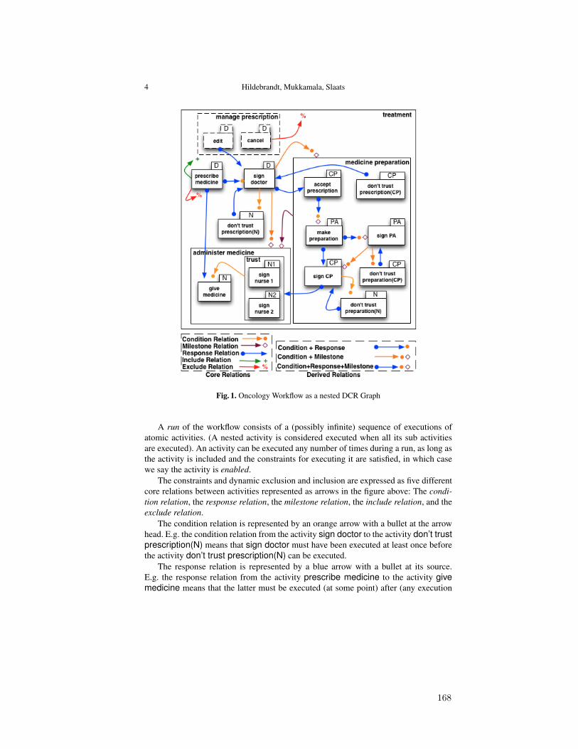
4 Hildebrandt, Mukkamala, Slaats
Fig. 1. Oncology Workflow as a nested DCR Graph
A run of the workflow consists of a (possibly infinite) sequence of executions ofatomic activities. (A nested activity is considered executed when all its sub activitiesare executed). An activity can be executed any number of times during a run, as long asthe activity is included and the constraints for executing it are satisfied, in which casewe say the activity is enabled.
The constraints and dynamic exclusion and inclusion are expressed as five differentcore relations between activities represented as arrows in the figure above: The condi-tion relation, the response relation, the milestone relation, the include relation, and theexclude relation.
The condition relation is represented by an orange arrow with a bullet at the arrowhead. E.g. the condition relation from the activity sign doctor to the activity don’t trustprescription(N) means that sign doctor must have been executed at least once beforethe activity don’t trust prescription(N) can be executed.
The response relation is represented by a blue arrow with a bullet at its source.E.g. the response relation from the activity prescribe medicine to the activity givemedicine means that the latter must be executed (at some point) after (any execution
168
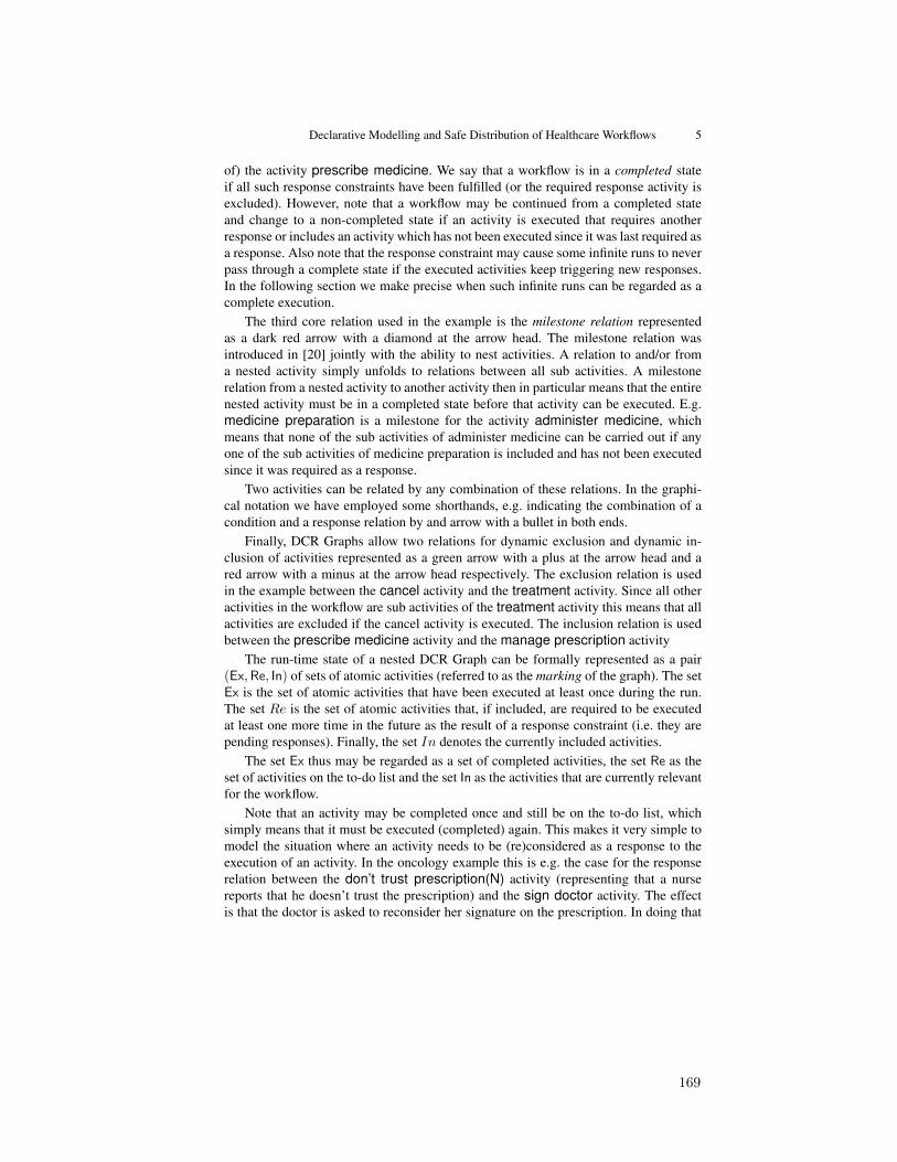
Declarative Modelling and Safe Distribution of Healthcare Workflows 5
of) the activity prescribe medicine. We say that a workflow is in a completed stateif all such response constraints have been fulfilled (or the required response activity isexcluded). However, note that a workflow may be continued from a completed stateand change to a non-completed state if an activity is executed that requires anotherresponse or includes an activity which has not been executed since it was last required asa response. Also note that the response constraint may cause some infinite runs to neverpass through a complete state if the executed activities keep triggering new responses.In the following section we make precise when such infinite runs can be regarded as acomplete execution.
The third core relation used in the example is the milestone relation representedas a dark red arrow with a diamond at the arrow head. The milestone relation wasintroduced in [20] jointly with the ability to nest activities. A relation to and/or froma nested activity simply unfolds to relations between all sub activities. A milestonerelation from a nested activity to another activity then in particular means that the entirenested activity must be in a completed state before that activity can be executed. E.g.medicine preparation is a milestone for the activity administer medicine, whichmeans that none of the sub activities of administer medicine can be carried out if anyone of the sub activities of medicine preparation is included and has not been executedsince it was required as a response.
Two activities can be related by any combination of these relations. In the graphi-cal notation we have employed some shorthands, e.g. indicating the combination of acondition and a response relation by and arrow with a bullet in both ends.
Finally, DCR Graphs allow two relations for dynamic exclusion and dynamic in-clusion of activities represented as a green arrow with a plus at the arrow head and ared arrow with a minus at the arrow head respectively. The exclusion relation is usedin the example between the cancel activity and the treatment activity. Since all otheractivities in the workflow are sub activities of the treatment activity this means that allactivities are excluded if the cancel activity is executed. The inclusion relation is usedbetween the prescribe medicine activity and the manage prescription activity
The run-time state of a nested DCR Graph can be formally represented as a pair(Ex,Re, In) of sets of atomic activities (referred to as the marking of the graph). The setEx is the set of atomic activities that have been executed at least once during the run.The set Re is the set of atomic activities that, if included, are required to be executedat least one more time in the future as the result of a response constraint (i.e. they arepending responses). Finally, the set In denotes the currently included activities.
The set Ex thus may be regarded as a set of completed activities, the set Re as theset of activities on the to-do list and the set In as the activities that are currently relevantfor the workflow.
Note that an activity may be completed once and still be on the to-do list, whichsimply means that it must be executed (completed) again. This makes it very simple tomodel the situation where an activity needs to be (re)considered as a response to theexecution of an activity. In the oncology example this is e.g. the case for the responserelation between the don’t trust prescription(N) activity (representing that a nursereports that he doesn’t trust the prescription) and the sign doctor activity. The effectis that the doctor is asked to reconsider her signature on the prescription. In doing that
169
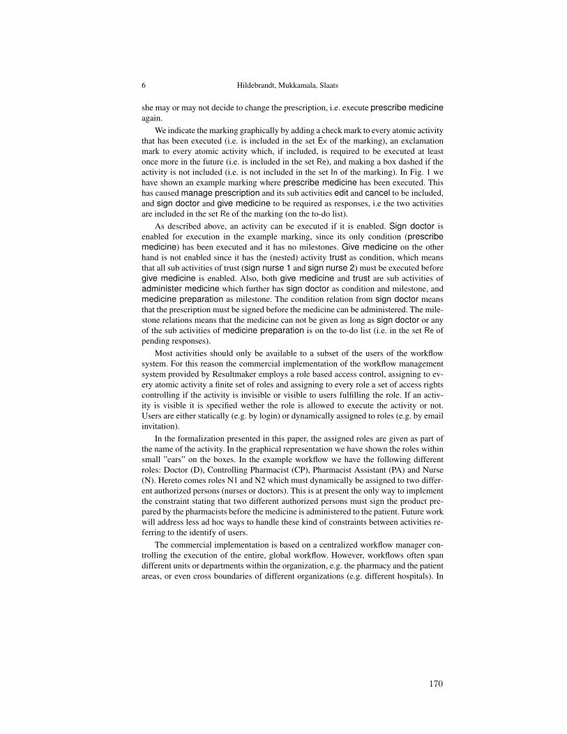
6 Hildebrandt, Mukkamala, Slaats
she may or may not decide to change the prescription, i.e. execute prescribe medicineagain.
We indicate the marking graphically by adding a check mark to every atomic activitythat has been executed (i.e. is included in the set Ex of the marking), an exclamationmark to every atomic activity which, if included, is required to be executed at leastonce more in the future (i.e. is included in the set Re), and making a box dashed if theactivity is not included (i.e. is not included in the set In of the marking). In Fig. 1 wehave shown an example marking where prescribe medicine has been executed. Thishas caused manage prescription and its sub activities edit and cancel to be included,and sign doctor and give medicine to be required as responses, i.e the two activitiesare included in the set Re of the marking (on the to-do list).
As described above, an activity can be executed if it is enabled. Sign doctor isenabled for execution in the example marking, since its only condition (prescribemedicine) has been executed and it has no milestones. Give medicine on the otherhand is not enabled since it has the (nested) activity trust as condition, which meansthat all sub activities of trust (sign nurse 1 and sign nurse 2) must be executed beforegive medicine is enabled. Also, both give medicine and trust are sub activities ofadminister medicine which further has sign doctor as condition and milestone, andmedicine preparation as milestone. The condition relation from sign doctor meansthat the prescription must be signed before the medicine can be administered. The mile-stone relations means that the medicine can not be given as long as sign doctor or anyof the sub activities of medicine preparation is on the to-do list (i.e. in the set Re ofpending responses).
Most activities should only be available to a subset of the users of the workflowsystem. For this reason the commercial implementation of the workflow managementsystem provided by Resultmaker employs a role based access control, assigning to ev-ery atomic activity a finite set of roles and assigning to every role a set of access rightscontrolling if the activity is invisible or visible to users fulfilling the role. If an activ-ity is visible it is specified wether the role is allowed to execute the activity or not.Users are either statically (e.g. by login) or dynamically assigned to roles (e.g. by emailinvitation).
In the formalization presented in this paper, the assigned roles are given as part ofthe name of the activity. In the graphical representation we have shown the roles withinsmall ”ears” on the boxes. In the example workflow we have the following differentroles: Doctor (D), Controlling Pharmacist (CP), Pharmacist Assistant (PA) and Nurse(N). Hereto comes roles N1 and N2 which must dynamically be assigned to two differ-ent authorized persons (nurses or doctors). This is at present the only way to implementthe constraint stating that two different authorized persons must sign the product pre-pared by the pharmacists before the medicine is administered to the patient. Future workwill address less ad hoc ways to handle these kind of constraints between activities re-ferring to the identify of users.
The commercial implementation is based on a centralized workflow manager con-trolling the execution of the entire, global workflow. However, workflows often spandifferent units or departments within the organization, e.g. the pharmacy and the patientareas, or even cross boundaries of different organizations (e.g. different hospitals). In
170

Declarative Modelling and Safe Distribution of Healthcare Workflows 7
some situations it may be very relevant to execute the local parts of the workflow on alocal (e.g. mobile) device without permanent access to a network, e.g. during prepara-tion of the medicine in the pharmacy. Also, different organizations may want to keepcontrol of their own parts of the workflow and not delegate the management to a cen-tral service. This motivates the ability to split the workflow in separate components,each only referring to the activities relevant for the local unit and being manageableindependently of the other components.
The technique for distributing DCR Graphs introduced in [21] and extended in thepresent paper is a first step towards supporting this kind of splitting of workflow def-initions. Given any division of activities on local units (assigning every activity to atleast one unit) it describes how to derive a set of graphs, one for each unit, describingthe local part of the workflow. Such a local process, referred to as a projection is againa DCR Graph. It includes the activities assigned to the unit but also the relevant exter-nal activities executed within other units for which an event must be send to the localprocess when they are executed. An example of a projection relative to the activitiesassigned the doctor role (D) is given in Fig. 2(a) in Sec. 4. The diagram shows thatthe projection also includes the two external activities (indicated as double line boxes)don’t trust prescription (N) and don’t trust prescription (CP). These two activities,representing respectively a nurse and a controlling pharmacist reporting that the pre-scription is not trusted, are the only external activities that may influence the workflowof the doctor by requiring sign doctor as a response. Similarly, Fig. 2(b),2(c), and 2(d)shows projections corresponding to the nurse, controlling pharmacist, and pharmacistassistant roles. However, if for instance the roles of the controlling pharmacist and thepharmacist assistant are always assigned to the same persons one may instead chooseto keep all these activities together in a unit. This can be obtained by simply projectingon all activities assigned either the CP or the PA role.
3 Nested Dynamic Condition Response Graphs
Dynamic Condition Response Graphs (DCR Graphs) [17] is both a generalization oflabelled event structures [47] and the Process Matrix workflow model developed byResultmaker, our industrial partner in the TrustCare research project. The DCR Graphswere extended in [20] to Nested DCR Graphs, supporting sub graphs and a new mile-stone relation, motivated by a case study of cross-organizational case management [19].Further in [21], we have considered safe distribution of DCR Graphs without milestonerelation where as in [18], we have defined projection and distribution for a restrictednested model Condition Response Graphs, simplified by not allowing the dynamic in-clusion and exclusion. In the present paper, we will consider full version of Nested DCRGraphs with both milestone and dynamic inclusion/exclusion relations and provide dis-tribution of nested DCR Graphs. We employ the following notations in the paper.Notation: For a set A we write P(A) for the power set of A. For a binary relation→⊆ A×A and a subset ξ ⊆ A of A we write→ξ and ξ→ for the set {a ∈ A | (∃a′ ∈ξ | a → a′)} and the set {a ∈ A | (∃a′ ∈ ξ | a′ → a)} respectively. Also, we write→−1 for the inverse relation. Finally, for a natural number k we write [k] for the set{1, 2, . . . , k}.
171

8 Hildebrandt, Mukkamala, Slaats
We then formally define nested dynamic condition response graph as follows.
Definition 1. A Dynamic Condition Response Graph (DCR Graph) G is a tuple (E,M,→•, •→,→�,→+,→%, L, l), where
(i) E is the set of events (or activities),(ii) M = (Ex,Re, In) ∈M(G) is the marking, forM(G) =def P(E)×P(E)×P(E),
(iii) →•⊆ E× E is the condition relation,(iv) •→⊆ E× E is the response relation,(v) →�⊆ E× E is the milestone relation,
(vi) →+,→%⊆ E×E is the dynamic include relation and exclude relation, satisfyingthat ∀e ∈ E.e→+ ∩e→%= ∅,
(vii) L is the set of labels,(viii) l : E→ P(L) is a labeling function mapping events to sets of labels.
A Nested Dynamic Condition Response Graph (Nested DCR Graph) G is a tuple (E,B,M,→•, •→,→�,→+,→%, L, l), where
(i) (E,M,→•, •→,→�,→+,→%, L, l) is a DCR Graph,(ii) B : E ⇀ E is a partial function mapping an event to its super-event (if defined),
(iii) M ∈ P(atoms(E)) × P(atoms(E)) × P(atoms(E)), where atoms(E) = E\{e ∈E | ∃e′ ∈ E.B (e′) = e} is the set of atomic events.
We write eB e′ if e′ = Bk(e) for 0 < k and write eD e′ if eB e′ or e = e′, and eE e′if e′ B e or e = e′. We require that the resulting relation,D ⊂ E ×E, referred to as thenesting relation, is a well founded partial order. We also require that the nesting relationis consistent with respect to dynamic inclusion/exclusion in the following sense: If eBe′or e′ B e then e→+ ∩e′ →%= ∅.
We already introduced the graphical notation for Nested DCR Graphs by example inthe previous section. We will not write out the complete formal specification. The eventsare all boxes, e.g. E = {treatment,manage prescription, prescribe medicine, ...}, thenesting relation captures the inclusion of boxes, e.g.B(e) = administer medicine, if e ∈{give medicine, trust} andB(e) = trust, if e ∈ {sign nurse1, sign nurse2} and so forth.The inital marking is the triple M = (∅, ∅,E\{manage prescription, edit, cancel}),meaning no events have been executed, no events are initially required as responses andall events except the events {manage prescription, edit, cancel} are included. The con-dition relation includes e.g. the pairs sign doctor →• don′t trust prescription(N) andtrust→• give medicine, the response relation includes e.g. the pairs prescribe medicine •→sign doctor and edit •→ sign doctor, the milestone relation includes e.g. the pairssign doctor →� administer medicine and sign PA →� sign CP, the dynamic inclusionrelation includes the single pair prescribe medicine →+ manage prescription and thedynamic exclusion includes exactly the two pairs prescribe medicine→% prescribe medicineand cancel →% treatment. We take as labels pairs of action names and roles, i.e. theset of labels L includes e.g. the pairs (edit,D), (cancel,D), (give medicine,N), and(sign PA,PA). Super events with no role assigned such as manage prescription are as-signed the empty set of labels.
Note that the labels of events consist of the name of the event and a role whichdefines who can execute that event. In our implementation every event can be assigned
172
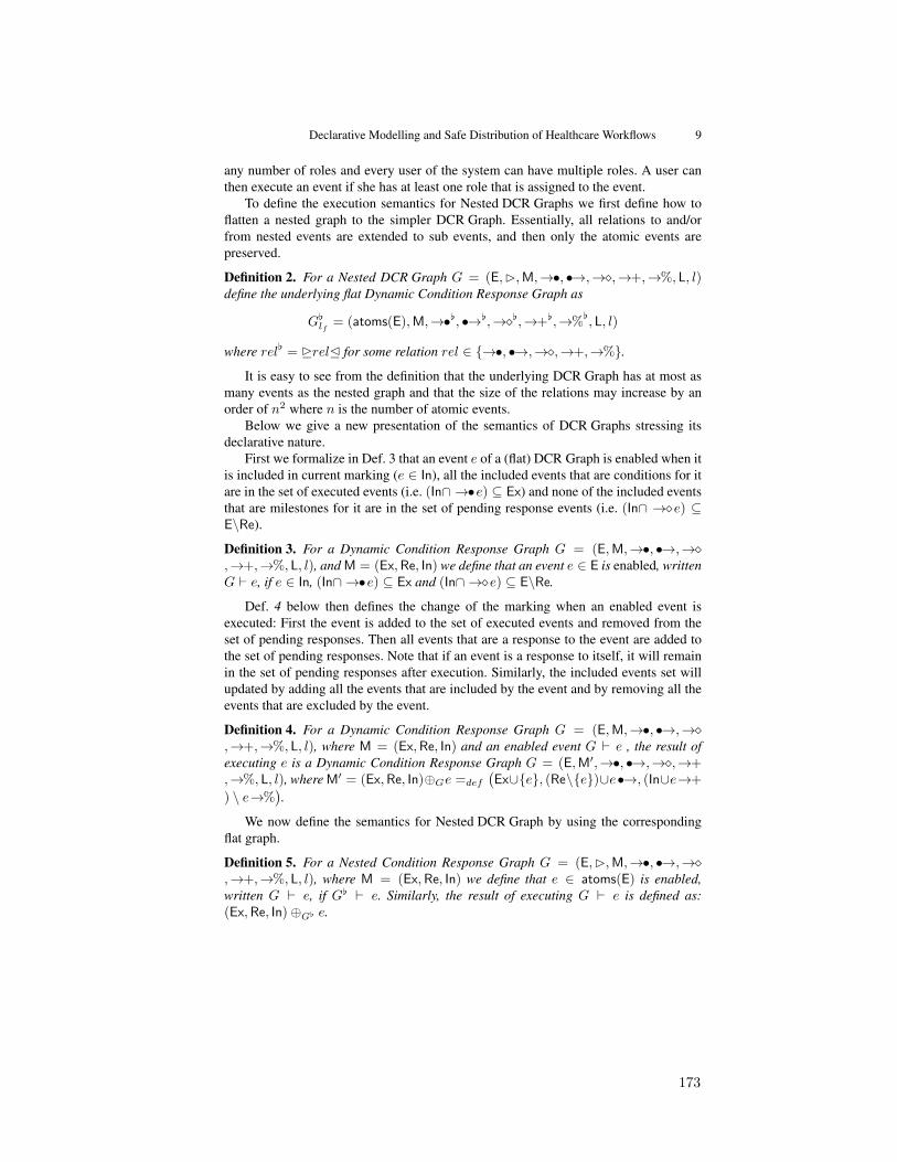
Declarative Modelling and Safe Distribution of Healthcare Workflows 9
any number of roles and every user of the system can have multiple roles. A user canthen execute an event if she has at least one role that is assigned to the event.
To define the execution semantics for Nested DCR Graphs we first define how toflatten a nested graph to the simpler DCR Graph. Essentially, all relations to and/orfrom nested events are extended to sub events, and then only the atomic events arepreserved.
Definition 2. For a Nested DCR Graph G = (E,B,M,→•, •→,→�,→+,→%, L, l)define the underlying flat Dynamic Condition Response Graph as
G[lf = (atoms(E),M,→•[, •→[,→�[,→+[,→%[, L, l)
where rel[ = DrelE for some relation rel ∈ {→•, •→,→�,→+,→%}.It is easy to see from the definition that the underlying DCR Graph has at most as
many events as the nested graph and that the size of the relations may increase by anorder of n2 where n is the number of atomic events.
Below we give a new presentation of the semantics of DCR Graphs stressing itsdeclarative nature.
First we formalize in Def. 3 that an event e of a (flat) DCR Graph is enabled when itis included in current marking (e ∈ In), all the included events that are conditions for itare in the set of executed events (i.e. (In∩ →•e) ⊆ Ex) and none of the included eventsthat are milestones for it are in the set of pending response events (i.e. (In∩ →�e) ⊆E\Re).
Definition 3. For a Dynamic Condition Response Graph G = (E,M,→•, •→,→�,→+,→%, L, l), and M = (Ex,Re, In) we define that an event e ∈ E is enabled, writtenG ` e, if e ∈ In, (In∩ →•e) ⊆ Ex and (In∩ →�e) ⊆ E\Re.
Def. 4 below then defines the change of the marking when an enabled event isexecuted: First the event is added to the set of executed events and removed from theset of pending responses. Then all events that are a response to the event are added tothe set of pending responses. Note that if an event is a response to itself, it will remainin the set of pending responses after execution. Similarly, the included events set willupdated by adding all the events that are included by the event and by removing all theevents that are excluded by the event.
Definition 4. For a Dynamic Condition Response Graph G = (E,M,→•, •→,→�,→+,→%, L, l), where M = (Ex,Re, In) and an enabled event G ` e , the result ofexecuting e is a Dynamic Condition Response Graph G = (E,M′,→•, •→,→�,→+,→%, L, l), where M′ = (Ex,Re, In)⊕Ge =def
(Ex∪{e}, (Re\{e})∪e•→, (In∪e→+
) \ e→%).
We now define the semantics for Nested DCR Graph by using the correspondingflat graph.
Definition 5. For a Nested Condition Response Graph G = (E,B,M,→•, •→,→�,→+,→%, L, l), where M = (Ex,Re, In) we define that e ∈ atoms(E) is enabled,written G ` e, if G[ ` e. Similarly, the result of executing G ` e is defined as:(Ex,Re, In)⊕G[ e.
173
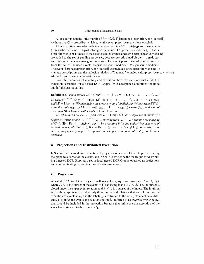
10 Hildebrandt, Mukkamala, Slaats
As an example, in the intial markingM = (∅, ∅,E\{manage prescription, edit, cancel})we have that G ` prescribe medicine, i.e. the event prescribe medicine is enabled.
After executing prescribe medicine the new markingM ′ =M⊕Gprescribe medicine =({prescribe medicine}, {sign doctor, give medicine},E\{prescribe medicine}). That is,prescribe medicine is added to the set of executed events, and sign doctor and give medicineare added to the set of pending responses, because prescribe medicine •→ sign doctorand prescribe medicine •→ give medicine}. The event prescribe medicine is removedfrom the set of included events because prescribe medicine →% prescribe medicine.The events {manage prescription, edit, cancel} are included since prescribe medicine→+manage prescription, and the inclusion relation is ”flattened” to include also prescribe medicine→+edit and prescribe medicine→+ cancel.
From the definition of enabling and execution above we can construct a labelledtransition semantics for a nested DCR Graphs, with acceptance conditions for finiteand infinite computations.
Definition 6. For a nested DCR Graph G = (E,B,M,→•, •→,→�,→+,→%, L, l)
we write G(e,a)−−−→ G′ if G′ = (E,B,M′,→•, •→,→�,→+,→%, L, l), G ` e, a ∈ l(e),
and M′ = M⊕G[ e. We then define the corresponding labelled transition system TS(G)to be the tuple (GE×L, G,E× L,→⊆ GE×L × E× L × GE×L) where GE×L is the set ofall nested DCR Graphs with events in E and labels in L.
We define a run a0, a1, . . . of a nested DCR Graph G to be a sequence of labels of a
sequence of transitionsGi(ei,ai)−−−−→ Gi+1. starting fromG0 = G. Assuming the marking
of Gi is (Exi,Rei, Ini), define a run to be accepting if for the underlying sequence oftransitions it holds that ∀i ≥ 0, e ∈ Rei.∃j ≥ i.(e = ej ∨ e 6∈ Inj). In words, a runis accepting if every required response event happens at some later stage or becomeexcluded.
4 Projections and Distributed Execution
In Sec. 4.1 below we define the notion of projection of a nested DCR Graphs, restrictingthe graph to a subset of the events, and in Sec. 4.2 we define the technique for distribut-ing a nested DCR Graph as a set of local nested DCR Graphs obtained as projectionsand communicating by notifications of event executions.
4.1 Projections
A nested DCR GraphG is projected with respect to a projection parameter δ = (δE, δL),where δE ⊆ E is a subset of the events ofG satisfying thatB(δE) ⊆ δE, i.e. the subset isclosed under the super event relation, and δL ⊆ L is a subset of the labels. The intuitionis that the graph is restricted to only those events and relations that are relevant for theexecution of events in δE and the labeling is restricted to the set δL. The technical diffi-culty is to infer the events and relations not in δE, referred to as external events below,that should be included in the projection because they influence the execution of theworkflow restricted to the events in δE.
174

Declarative Modelling and Safe Distribution of Healthcare Workflows 11
(a) Projection over D (b) Projection over N and N1
(c) Projection over CP (d) Projection over PA
Fig. 2. Oncology workflow projected with respect to different roles
Fig. 2 shows examples of projections of the oncology workflow with respect todifferent roles. For instance, Fig. 2(a) shows the projection with respect to the pro-jection parameter (δE, δL) where δE={manage prescription, edit, cancel, prescribemedicine, sign doctor} and δL={(edit, D), (cancel, D), (prescribe medicine, D),(sign doctor, D)}. The two events don’t trust prescription (N) and don’t trust pre-scription (CP) shown with double line borders are external events included in the pro-jected graph even though they don’t appear in the projection parameter. It is interestingto note that the doctor only needs to be aware of these two activities carried out byother participants. In comparison, the projection over the roles for nurses (N and N1)contains all the events since they may influence (because of the milestone relations) theexecution of the events with roles N and N1. In other words, the doctors can carry outworkflows highly independent of the other activities while the nurses are dependent onany event carried out by the other roles.
175
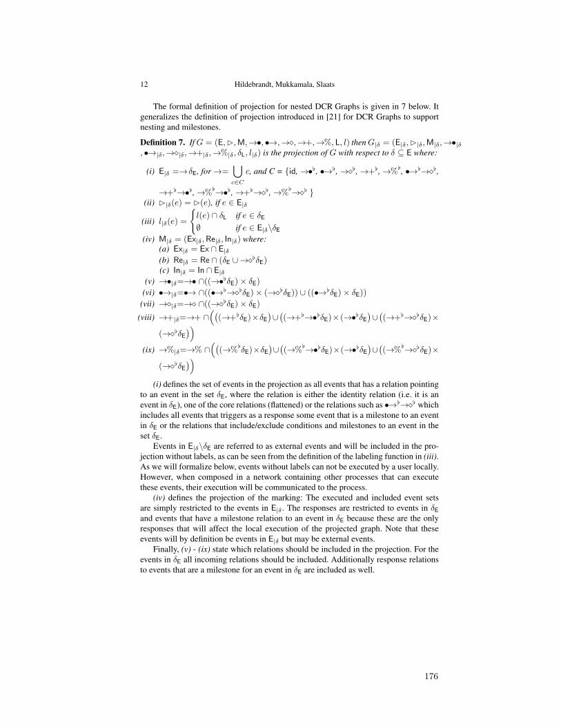
12 Hildebrandt, Mukkamala, Slaats
The formal definition of projection for nested DCR Graphs is given in 7 below. Itgeneralizes the definition of projection introduced in [21] for DCR Graphs to supportnesting and milestones.
Definition 7. IfG = (E,B,M,→•, •→,→�,→+,→%, L, l) thenG|δ = (E|δ,B|δ,M|δ,→•|δ, •→|δ,→�|δ,→+|δ,→%|δ, δL, l|δ) is the projection of G with respect to δ ⊆ E where:
(i) E|δ =→δE, for→=⋃
c∈Cc, and C = {id,→•[, •→[,→�[,→+[,→%
[, •→[→�[,
→+[→•[,→%[→•[,→+[→�[,→%
[→�[ }(ii) B|δ(e) = B(e), if e ∈ E|δ
(iii) l|δ(e) =
{l(e) ∩ δL if e ∈ δE
∅ if e ∈ E|δ\δE
(iv) M|δ = (Ex|δ,Re|δ, In|δ) where:(a) Ex|δ = Ex ∩ E|δ(b) Re|δ = Re ∩ (δE ∪→�[δE)(c) In|δ = In ∩ E|δ
(v) →•|δ=→• ∩((→•[δE)× δE)
(vi) •→|δ=•→ ∩((•→[→�[δE)× (→�[δE)) ∪ ((•→[δE)× δE))
(vii) →�|δ=→� ∩((→�[δE)× δE)
(viii) →+|δ=→+ ∩((
(→+[δE)×δE
)∪((→+[→•[δE)×(→•[δE
)∪((→+[→�[δE)×
(→�[δE
))
(ix) →%|δ=→% ∩((
(→%[δE)×δE
)∪((→%
[→•[δE)×(→•[δE
)∪((→%
[→�[δE)×(→�[δE
))
(i) defines the set of events in the projection as all events that has a relation pointingto an event in the set δE, where the relation is either the identity relation (i.e. it is anevent in δE), one of the core relations (flattened) or the relations such as •→[→�[ whichincludes all events that triggers as a response some event that is a milestone to an eventin δE or the relations that include/exclude conditions and milestones to an event in theset δE.
Events in E|δ\δE are referred to as external events and will be included in the pro-jection without labels, as can be seen from the definition of the labeling function in (iii).As we will formalize below, events without labels can not be executed by a user locally.However, when composed in a network containing other processes that can executethese events, their execution will be communicated to the process.
(iv) defines the projection of the marking: The executed and included event setsare simply restricted to the events in E|δ . The responses are restricted to events in δE
and events that have a milestone relation to an event in δE because these are the onlyresponses that will affect the local execution of the projected graph. Note that theseevents will by definition be events in E|δ but may be external events.
Finally, (v) - (ix) state which relations should be included in the projection. For theevents in δE all incoming relations should be included. Additionally response relationsto events that are a milestone for an event in δE are included as well.
176
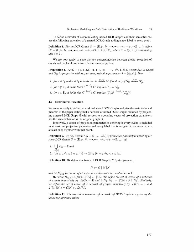
Declarative Modelling and Safe Distribution of Healthcare Workflows 13
To define networks of communicating nested DCR Graphs and their semantics weuse the following extension of a nested DCR Graph adding a new label to every event.
Definition 8. For an DCR Graph G = (E,B,M,→•, •→,→�,→+,→%, L, l) defineGε = (E,B,M,→•, •→,→�,→+,→%, L∪{ε}, lε), where lε = l(e)∪{ε} (assumingthat ε 6∈ L).
We are now ready to state the key correspondence between global execution ofevents and the local execution of events in a projection.
Proposition 1. LetG = (E,B,M,→•, •→,→�,→+,→%, L, l) be a nested DCR Graphand G|δ its projection with respect to a projection parameter δ = (δE, δL). Then
1. for e ∈ δE and a ∈ δL it holds that G(e,a)−−−→ G′ if and only if G|δ
(e,a)−−−→ G′|δ ,
2. for e 6∈ E|δ it holds that G(e,a)−−−→ G′ implies G|δ = G′|δ ,
3. for e ∈ E|δ it holds that G(e,a)−−−→ G′ implies (G|δ)ε
(e,ε)−−−→ (G′|δ)ε,
4.2 Distributed Execution
We are now ready to define networks of nested DCR Graphs and give the main technicaltheorem of the paper stating that a network of nested DCR Graphs obtained by project-ing a nested DCR Graph G with respect to a covering vector of projection parametershas the same behavior as the original graph G.
Intuitively, a vector of projection parameters is covering if every event is includedin at least one projection parameter and every label that is assigned to an event occursat least once together with that event.
Definition 9. We call a vector ∆ = (δ1, . . . , δk) of projection parameters covering forsome DCR Graph G = (E,B,M,→•, •→,→�,→+,→%, L, l) if:
1.⋃
i∈[k]δEi = E and
2. (∀a ∈ L.∀e ∈ E.a ∈ l(e)⇒ (∃i ∈ [k].e ∈ δEi ∧ a ∈ δLi)
Definition 10. We define a network of DCR Graphs N by the grammar
N := G | N‖Nand let NE×L be the set of all networks with events in E and labels in L.
We write Πi∈[n]Gi for G1‖G2‖ . . . ‖Gn. We define the set of events of a networkof graphs inductively by E(G) = E and E(N1‖N2) = E(N1) ∪ E(N2). Similarly,we define the set of labels of a network of graphs inductively by L(G) = L andL(N1‖N2) = L(N1) ∪ L(N2).
Definition 11. The transition semantics of networks of DCR Graphs are given by thefollowing inference rules:
177
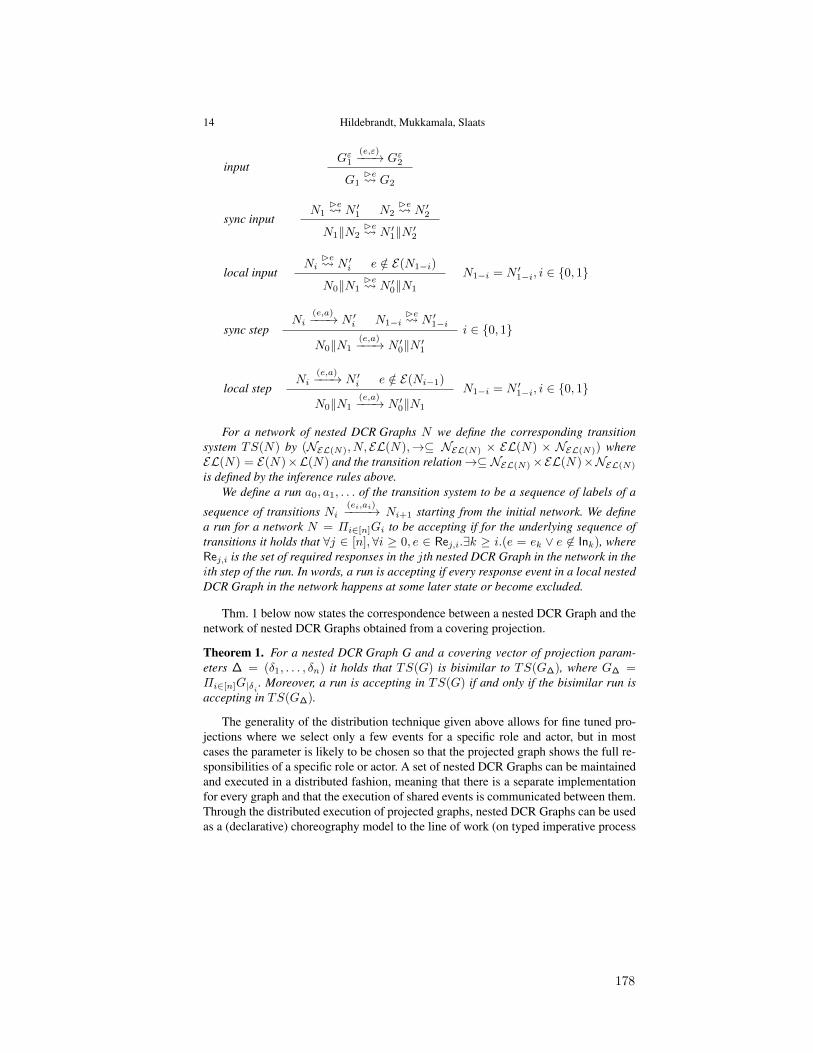
14 Hildebrandt, Mukkamala, Slaats
inputGε1
(e,ε)−−−→ Gε2
G1Be G2
sync inputN1
Be N ′1 N2Be N ′2
N1‖N2Be N ′1‖N ′2
local inputNi
Be N ′i e /∈ E(N1−i)
N0‖N1Be N ′0‖N1
N1−i = N ′1−i, i ∈ {0, 1}
sync stepNi
(e,a)−−−→ N ′i N1−iBe N ′1−i
N0‖N1(e,a)−−−→ N ′0‖N ′1
i ∈ {0, 1}
local stepNi
(e,a)−−−→ N ′i e /∈ E(Ni−1)
N0‖N1(e,a)−−−→ N ′0‖N1
N1−i = N ′1−i, i ∈ {0, 1}
For a network of nested DCR Graphs N we define the corresponding transitionsystem TS(N) by (NEL(N), N, EL(N),→⊆ NEL(N) × EL(N) × NEL(N)) whereEL(N) = E(N)×L(N) and the transition relation→⊆ NEL(N)×EL(N)×NEL(N)
is defined by the inference rules above.We define a run a0, a1, . . . of the transition system to be a sequence of labels of a
sequence of transitions Ni(ei,ai)−−−−→ Ni+1 starting from the initial network. We define
a run for a network N = Πi∈[n]Gi to be accepting if for the underlying sequence oftransitions it holds that ∀j ∈ [n],∀i ≥ 0, e ∈ Rej,i.∃k ≥ i.(e = ek ∨ e 6∈ Ink), whereRej,i is the set of required responses in the jth nested DCR Graph in the network in theith step of the run. In words, a run is accepting if every response event in a local nestedDCR Graph in the network happens at some later state or become excluded.
Thm. 1 below now states the correspondence between a nested DCR Graph and thenetwork of nested DCR Graphs obtained from a covering projection.
Theorem 1. For a nested DCR Graph G and a covering vector of projection param-eters ∆ = (δ1, . . . , δn) it holds that TS(G) is bisimilar to TS(G∆), where G∆ =Πi∈[n]G|δi . Moreover, a run is accepting in TS(G) if and only if the bisimilar run isaccepting in TS(G∆).
The generality of the distribution technique given above allows for fine tuned pro-jections where we select only a few events for a specific role and actor, but in mostcases the parameter is likely to be chosen so that the projected graph shows the full re-sponsibilities of a specific role or actor. A set of nested DCR Graphs can be maintainedand executed in a distributed fashion, meaning that there is a separate implementationfor every graph and that the execution of shared events is communicated between them.Through the distributed execution of projected graphs, nested DCR Graphs can be usedas a (declarative) choreography model to the line of work (on typed imperative process
178
Declarative Modelling and Safe Distribution of Healthcare Workflows 15
models) in [6]: The original graph can be seen as the choreography, describing howthe system as a whole should function, from which we project multiple end-points forindividual roles or actors that can be implemented independently.
5 Conclusion and Future Work
We have presented a formal technique for safe distribution of collaborative, cross-organizational workflows modeled declaratively in the model of Nested Dynamic Con-dition Response (Nested DCR) Graphs [17,20]. The key difference between the presentwork and the related work surveyed in Sec. 1.1 is that Nested DCR Graphs is a declar-ative model while most previous work has focussed on imperative models. We haveargued for the use of a declarative approach for flexible workflows of knowledge work-ers and exemplified the techniques on a small workflow identified during a previousfield study at danish hospitals [26]. The example is not supposed to demonstrate com-pleteness of the technique but to capture two common examples of flexibility, namelythe need to reconsider previous activities and the flexibility to distribute the executionof a workflow across different units within or across organizations.
The distribution technique presented is an extension of a method developed recentlyfor flat DCR Graphs [21] to allow for nesting of events and the co-called milestonerelations. This again allows us to apply the technique to the oncology workflow whichwe believe is an important new contribution in order to communicate the ideas better topeople working within the healthcare domain.
A number of interesting questions are left for future work. We have implemented aprototype tool for design, simulation and verification (model checking via the SPIN andZING model checkers) of DCR Graphs as reported on in [19]. These tools should be ex-tended to nested graphs and the distribution technique should be implemented. This thenleads to considering what can be achieved by performing verification of local compo-nents individually. We also aim to investigate how to support dynamic changes to localcomponents, using the underlying idea of the distribution technique to determine whatshould be changed in other components when a local component is changed. Finallywe are working on extending the model to allow for data and time to be representedand developing a prototype implementation integrated with the work on pervasive userinterfaces carried out in the other track of the TrustCare project. This would allow usto carry out a larger demonstration project jointly with a hospital evaluating both theworkflow modeling and the pervasive user interfaces. Along the same lines, it would beinteresting to relate our work to the approach in the OpenKnowledge and Safe & Soundprojects based on the Lightweight Coordination Calculus (LCC) [37].Acknowledgements: We are grateful to the anonymous reviewers for valuable feed-back.
References
1. Wil M. P. van der Aalst and Mathias Weske. The p2p approach to interorganizational work-flows. In Proceedings of the 13th International Conference on Advanced Information Sys-tems Engineering, CAiSE ’01, pages 140–156, 2001.
179

16 Hildebrandt, Mukkamala, Slaats
2. Jakob E. Bardram, Jonathan Bunde-Pedersen, Afsaneh Doryab, and Steffen Sorensen. Clin-ical surfaces: Activity-based computing support for distributed multi-display environmentsinside hospitals. In INTERACT 2009: 12th IFIP TC13 Conference in Human-Computer In-teraction, Uppsala, Sweden, 2009.
3. Jakob E. Bardram, Jonathan Bunde-Pedersen, and Mads Soegaard. Support for activity-based computing in a personal computing operating system. In CHI ’06: Proceedings of theSIGCHI conference on Human Factors in computing systems, pages 211–220, New York,NY, USA, 2006. ACM Press.
4. Mario Bravetti and Gianluigi Zavattaro. Contract based multi-party service composition. InInternational Symposium on Fundamentals of Software Engineering (FSEN), volume 4767,pages 207–222. Springer, 2007.
5. Mario Bravetti and Gianluigi Zavattaro. A theory of contracts for strong service compliance.Mathematical. Structures in Comp. Sci., 19:601–638, June 2009.
6. Marco Carbone, Kohei Honda, and Nobuko Yoshida. Structured Communication-CentredProgramming for Web Services. In 16th European Symposium on Programming (ESOP’07),LNCS, pages 2–17. Springer, 2007.
7. Ilaria Castellani, Madhavan Mukund, and P. Thiagarajan. Synthesizing distributed transitionsystems from global specifications. In Foundations of Software Technology and TheoreticalComputer Science, volume 1738, pages 219–231. Springer Berlin / Heidelberg, 1999.
8. Federico Chesani, Pietro De Matteis, Paola Mello, Marco Montali, and Sergio Storari. Aframework for defining and verifying clinical guidelines: A case study on cancer screening.In Floriana Esposito, Zbigniew Ras, Donato Malerba, and Giovanni Semeraro, editors, Foun-dations of Intelligent Systems, volume 4203 of Lecture Notes in Computer Science, pages338–343. Springer Berlin / Heidelberg, 2006.
9. Federico Chesani, E. Lamma, P. Mello, M. Montali, S. Storari, P. Baldazzi, and M. Man-fredi. Compliance Checking of Cancer-Screening Careflows: an Approach Based on Com-putational Logic, chapter Computer- Based Medical Guidelines and Protocols: a Primer andCurrent Trends. IOS Press, 2008.
10. Federico Chesani, Paola Mello, Marco Montali, and Sergio Storari. Testing careflow pro-cess execution conformance by translating a graphical language to computational logic. InRiccardo Bellazzi, Ameen Abu-Hanna, and Jim Hunter, editors, Artificial Intelligence inMedicine, volume 4594 of Lecture Notes in Computer Science, pages 479–488. SpringerBerlin / Heidelberg, 2007.
11. Dirk Fahland. Towards analyzing declarative workflows. In Autonomous and Adaptive WebServices, 2007.
12. Walid Fdhila and Claude Godart. Toward synchronization between decentralized orchestra-tions of composite web services. In CollaborateCom’09, pages 1–10, 2009.
13. Walid Fdhila, Ustun Yildiz, and Claude Godart. A flexible approach for automatic processdecentralization using dependency tables. International Conference on Web Services, 2009.
14. Xiang Fu, Tevfik Bultan, and Jianwen Su. Realizability of conversation protocols with mes-sage contents. In Proceedings of the IEEE International Conference on Web Services, ICWS’04, pages 96–, Washington, DC, USA, 2004. IEEE Computer Society.
15. Keijo Heljanko and Alin Stefanescu. Complexity results for checking distributed imple-mentability. In Proceedings of the Fifth International Conference on Application of Concur-rency to System Design, pages 78–87, 2005.
16. Thomas Hildebrandt. Trustworthy pervasive healthcare processes (TrustCare) researchproject. Webpage, 2008. http://www.trustcare.dk/.
17. Thomas Hildebrandt and Raghava Rao Mukkamala. Declarative event-based workflow asdistributed dynamic condition response graphs. In Post proceedings of International Work-shop on Programming Language Approaches to Concurrency and Communication-cEntricSoftware (PLACES 10), 2011.
180
Declarative Modelling and Safe Distribution of Healthcare Workflows 17
18. Thomas Hildebrandt, Raghava Rao Mukkamala, and Tijs Slaats. Declarative modelling andsafe distribution of healthcare workflows. In International Symposium on Foundations ofHealth Information Engineering and Systems, Johannesburg, South Africa, August 2011.
19. Thomas Hildebrandt, Raghava Rao Mukkamala, and Tijs Slaats. Designing a cross-organizational case management system using dynamic condition response graphs. In Pro-ceedings of IEEE International EDOC Conference, 2011. to appear.
20. Thomas Hildebrandt, Raghava Rao Mukkamala, and Tijs Slaats. Nested dynamic conditionresponse graphs. In Proceedings of Fundamentals of Software Engineering (FSEN), April2011. to appear.
21. Thomas Hildebrandt, Raghava Rao Mukkamala, and Tijs Slaats. Safe distribution of declar-ative processes. In 9th International Conference on Software Engineering and Formal Meth-ods (SEFM) 2011, 2011. to appear.
22. International symposium on foundations of health information engineering and systems, Au-gust 2011.
23. Ali Rahmanzadeh John Fox, Nicky Johns. Disseminating medical knowledge: the proformaapproach. Artificial intelligence in medicine, 14:157–182, September 1998.
24. R. Khalaf and F. Leymann. Role-based decomposition of business processes using BPEL.In Web Services, 2006. ICWS ’06. International Conference on, pages 770 –780, sept. 2006.
25. Ekkart Kindler, Axel Martens, and Wolfgang Reisig. Inter-operability of workflow appli-cations: Local criteria for global soundness. In Business Process Management, Models,Techniques, and Empirical Studies, pages 235–253, London, UK, 2000. Springer-Verlag.
26. Karen Marie Lyng, Thomas Hildebrandt, and Raghava Rao Mukkamala. From paper basedclinical practice guidelines to declarative workflow management. In Proceedings of 2ndInternational Workshop on Process-oriented information systems in healthcare (ProHealth08), pages 36–43, Milan, Italy, 2008. BPM 2008 Workshops.
27. Axel Martens. Analyzing web service based business processes. In Fundamental Approachesto Software Engineering. Springer Berlin / Heidelberg, 2005.
28. Zoran Milosevic, Shazia Sadiq, and Maria Orlowska. Towards a methodology for derivingcontract-compliant business processes. In Business Process Management, volume 4102 ofLecture Notes in Computer Science, pages 395–400. Springer Berlin / Heidelberg, 2006.
29. Saayan Mitra, Ratnesh Kumar, and Samik Basu. Optimum decentralized choreography forweb services composition. In Proceedings of the 2008 IEEE International Conference onServices Computing - Volume 2, 2008.
30. Marco Montali. Specification and Verification of Declarative Open Interaction Models: ALogic-Based Approach, volume 56 of Lecture Notes in Business Information Processing.Springer, 2010.
31. Raghava Rao Mukkamala, Thomas Hildebrandt, and Janus Boris Tøth. The resultmakeronline consultant: From declarative workflow management in practice to LTL. In Proceedingof DDBP, 2008.
32. M. Mukund. From global specifications to distributed implementations. In Synthesis andControl of Discrete Event Systems. Springer, 2002.
33. Nataliya Mulyar, Maja Pesic, Wil M. P. Van Der Aalst, and Mor Peleg. Declarative and pro-cedural approaches for modelling clinical guidelines: addressing flexibility issues. In Pro-ceedings of the 2007 international conference on Business process management, BPM’07,pages 335–346, Berlin, Heidelberg, 2008. Springer-Verlag.
34. Mangala Gowri Nanda, Satish Chandra, and Vivek Sarkar. Decentralizing execution of com-posite web services. SIGPLAN Not., 39:170–187, October 2004.
35. Object Management Group BPMN Technical Committee. Business Process Model and No-tation, version 2.0. Webpage, january 2011. http://www.omg.org/spec/BPMN/2.0/PDF.
181
18 Hildebrandt, Mukkamala, Slaats
36. Stefanie Rinderle, Andreas Wombacher, and Manfred Reichert. Evolution of process chore-ographies in dychor. In On the Move to Meaningful Internet Systems 2006: CoopIS, DOA,GADA, and ODBASE, volume 4275 of LNCS, pages 273–290. Springer, 2006.
37. David Robertson. A lightweight coordination calculus for agent systems. In In DeclarativeAgent Languages and Technologies, pages 183–197, 2004.
38. W. Sadiq, S. Sadiq, and K. Schulz. Model driven distribution of collaborative business pro-cesses. In Services Computing, 2006. SCC ’06. IEEE International Conference on, pages281 –284, sept. 2006.
39. Arthur ter Hofstede, Rob van Glabbeek, and David Stork. Query nets: Interacting workflowmodules that ensure global termination. In Business Process Management. Springer Berlin /Heidelberg, 2003.
40. P Terenziani, S Montani, A Bottrighi, M Torchio, G Molino, and G. Correndo. The glareapproach to clinical guideline: Main features. Symposium on Computerized Guidelines andProtocols, 101:62–6, April 2004.
41. W. M. P. van der Aalst. Interorganizational workflows: An approach based on messagesequence charts and petri nets. Systems Analysis - Modelling - Simulation, 34(3):335–367,1999.
42. Wil M. P. van der Aalst, Niels Lohmann, Peter Massuthe, Christian Stahl, and Karsten Wolf.Multiparty Contracts: Agreeing and Implementing Interorganizational Processes. The Com-puter Journal, 53(1):90–106, January 2010.
43. Wil M. P. van der Aalst, Maja Pesic, and Helen Schonenberg. Declarative workflows: Bal-ancing between flexibility and support. Computer Science - R&D, 23(2):99–113, 2009.
44. Wil M.P van der Aalst and Maja Pesic. A declarative approach for flexible business processesmanagement. In Proceedings DPM 2006, LNCS. Springer Verlag, 2006.
45. Wil M.P van der Aalst and Maja Pesic. DecSerFlow: Towards a truly declarative service flowlanguage. In M. Bravetti, M. Nunez, and Gianluigi Zavattaro, editors, Proceedings of WebServices and Formal Methods (WS-FM 2006), volume 4184 of LNCS, pages 1–23. SpringerVerlag, 2006.
46. W.M.P. van der Aalst. Inheritance of interorganizational workflows: How to agree to disagreewithout loosing control? Information Technology and Management, 4:345–389, 2003.
47. Glynn Winskel. Event structures. In Wilfried Brauer, Wolfgang Reisig, and Grzegorz (Eds.)Rozenberg, editors, Advances in Petri Nets, volume Vol. 255 of Lecture Notes in ComputerScience,, pages 325–392. Springer, 1986.
48. Dirk Wodtke and Gerhard Weikum. A formal foundation for distributed workflow execu-tion based on state charts. In Proceedings of the 6th International Conference on DatabaseTheory, pages 230–246, London, UK, 1997. Springer-Verlag.
49. X. Yi and K.J Kochut. Process composition of web services with complex conversation pro-tocols. In Design, Analysis, and Simulation of Distributed Systems Symposium at AdavancedSimulation Technology, 2004.
50. W. Zielonka. Notes on finite asynchronous automata. Informatique Thorique et Applications,21(2):99–135, 1987.
182
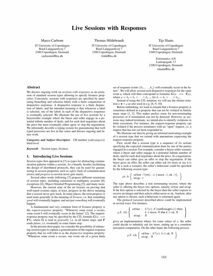
Live Sessions with Responses
Marco CarboneIT University of Copenhagen
Rued Langgaardsvej 72300 Copenhagen, Denmark
Thomas HildebrandtIT University of Copenhagen
Rued Langgaardsvej 72300 Copenhagen, Denmark
Tijs SlaatsIT University of Copenhagen
Rued Langgaardsvej 72300 Copenhagen, Denmark
Exformatics A/SLautrupsgade 13
2100 Copenhagen, [email protected]
AbstractWe discuss ongoing work on sessions with responses as an exten-sion of standard session types allowing to specify liveness prop-erties. Concretely, sessions with responses are specified by anno-tating branching and selection labels with a finite conjunction ofdisjunctive responses. A disjunctive response is a finite disjunc-tion of labels, and the intended meaning is that whenever a labelis selected, one of the labels in each of the disjunctive responsesis eventually selected. We illustrate the use of live sessions by abuyer/seller example where the buyer and seller engage in a po-tential infinite number of deals, and for each deal negotiates aboutthe price but must eventually either agree or stop the negotiation.We informally describe a typing system for guaranteeing that welltyped processes are live in this sense and discuss ongoing and fu-ture work.
Categories and Subject Descriptors CR-number [subcategory]:third-level
Keywords Session types, liveness
1. Introducing Live SessionsSession types first appeared in [7] as types for abstracting commu-nication patterns within a session. As a benefit, besides facilitatingthe design of distributed protocols, they can be used for guaran-teeing in-session properties such as safety (lack of communicationerrors) and progress (a session never gets stuck).
Several other works following [7] propose different extensionsof session types, including extensions to multiparty sessions [8],exceptions [4], Object-Oriented Programming [5], and many more.
However, the current state of the art focuses on proving thatwell-typed systems enjoy, at least, progress in the above meaningthat a session never gets stuck. In many places, the term progress isused more generally in the meaning of liveness, i.e. that somethinggood will eventually happen, and not just something will eventuallyhappen.
A fundamental and very common form of liveness property isthe request-response property: ”Whenever some event a occurs,some event b will eventually occur in the future” [2]. The request-response property may be specified by the LTL formula G(a =⇒Fb), where G is read as generally, i.e. in all future steps, and Freads future, i.e. eventually in some future step.
In the present short paper, we consider the possibility of enhanc-ing session types to capture a generalization of the request-responseproperty that we will refer to as the disjunctive response property:”Whenever some event a occurs, one event out of a given finite
set of response events {b1, . . . , bn} will eventually occur in the fu-ture”. We will allow several such disjunctive responses for the sameevent a, which will then correspond to formulas G(a =⇒ Fρ),where ρ = δ0 ∧ δ1 ∧ . . . ∧ δn−1 for δi = b1 ∨ . . . ∨ bmi .
Instead of using the LTL notation, we will use the shorter nota-tion a •→ ρ as also used in e.g. [6, 9, 10].
Before embarking, we want to remark that a liveness property issometimes defined as a property that can not be violated in finitelymany steps [1, 2]. This makes perfect sense for non-terminatingprocesses or if termination can not be detected. However, as ses-sions may indeed terminate, we intend also to identify violations infinite executions. For instance, the request-response property canbe violated if the process terminates with an ”open” request, i.e. arequest that has not yet been responded to.
We illustrate our idea by giving an informal motivating exampleof a session type that we extend with annotations expressing therequest-response property.
First, recall that a session type is a sequence of i/o actionsspecifying the expected communication done by one of the partiesengaged in a session. For example, consider a buyer-seller scenariowhere a buyer and seller engage in a potential infinite number ofdeals, and for each deal negotiates about the price. In a negotiation,the buyer can either give an offer or stop the negotiation. If thebuyer gives an offer, the seller can either ask for more or say it isok. In a such a scenario, the seller’s behaviour could be specifiedby the following session type:
µt. &
{offer :?(int). ⊕ { more : t, ok : t},stop : t
}
The type above describes a non terminating session, where theseller is offering the buyer two options, namely offer and stop.If the first option is selected by the buyer then the seller expects toreceive an integer and then selects either more or ok. Anyhow, afterany option is chosen, such a behaviour is reiterated again.
The protocol (session) described above could be implementedin several ways. For instance,
µX. k&
offer : k?(x). if (notEnough(x)) thenk ⊕ more. X else k ⊕ ok. X
stop : X
gives an implementation where, for some values of x, the sellercould decide to infinitely ask for more, ending up in a somehowunwanted computation. On the other hand, the following process
µX. k&
{offer : k?(x). k ⊕ ok. Xstop : X
}
183
still implements the session described by our type, but satisfyingthe liveness property that if an offer is made, this deal is eventuallyended.
The example illustrates, that it would be relevant to constrainthe session protocol further to require request-response livenessproperties, where the usual in-session selection of branches can beused in the specification as request and response events.
We suggest that such properties could be intuitively expressedby allowing branching and selection labels to be annotated with a(conjunction of) disjunctive response requirements.
For instance, if we wanted to require that the ok or stop branchmust eventually be selected if an offer is made, we could add thefollowing annotation to the type above.
µt. &
{offer[ok ∨ stop] :?(int). ⊕ { more : t, ok : t},stop : t
}
The first process above should then not be well-typed, while thesecond should pass the type check.
2. Session Calculus and the Liveness PropertyAs session calculus we may use a variant of the π-calculus withsessions [7, 11] which outlaws restriction on public channels, andallows replicated behaviour only for services. This choice is notcrucial for the definition of live-sessions.
Semantics As semantics we use the standard reduction seman-tics→ [7] except selection reduction steps are annotated with theselected label. This allows us to define the trace language for a pro-cess and the liveness properties our type system will enforce. LetTr(P) refer to the set of finite and infinite traces of labels of theprocess P.
Liveness We can now define the liveness property proposed inour introduction.
DEFINITION 1 (Liveness). Assume a disjunctive response ρ =δ0 ∧ δ1 ∧ . . .∧ δn−1 for δi = li,1 ∨ . . .∨ li,mi . A trace σ ∈ Tr(P)of a process P then satisfies the request-response liveness propertyl •→ ρ if for all k < |σ|, if σk = l then for all i ∈ {0, . . . , n− 1}there exists j ∈ {1, . . . ,mi} such that there exists k′ > k forwhich σk′ = li,j .
We say that a process P has the liveness property wrt a set ofresponse liveness propertiesP whenever each trace σ of P satisfiesevery property in P .
The intuitive meaning of the liveness property is as stated in theprevious section, that a trace satisfy the property l •→ δ forδ = l1 ∨ . . . lm if any occurrence of the label l is eventuallyfollowed by a label li for some i ∈ {0, . . . ,m}, and in general,a trace satisfies the property l •→ ρ for ρ = δ0 ∧ . . . δn−1 if itsatisfies l •→ δj for all j ∈ {0, . . . , n− 1}.
3. Live Session TypingSession Types with Responses. The generalization of sessiontypes to session types with responses is given by the followinggrammar:
α ::= ?(θ). α | !(θ). α | &{li[ρi] : αi} | ⊕{li[ρi] : αi} |end | µt. α | t
θ ::= S | α S ::= basic | 〈α〉ρ ::= > | δ | ρ ∧ ρ δ ::= l | δ ∨ δ
Here, ?(θ). α and !(θ). α denote in-session input and outputfollowed by the communications in α. The type θ abstracts whatis communicated: a basic value (basic denotes basic types, e.g., int
or bool), a service channel of type 〈α〉, or a session channel of typeα. Finally, &{li[ρi] : αi} and ⊕{li[ρi] : αi} denote branchingand selection types, and end is the inactive session. Branchingand selection have been enhanced with disjunctive responses (ρ) asintroduced in the previous section. The response> (true) representsthe empty response, and thus we will usually write l for l[>].
4. Conclusions, Ongoing and Future WorkAbove we have suggested extending session types to allow ex-pressing liveness properties. As a starting point, we consideredliveness properties stated as a generalisation of the fundamentalrequest-response pattern. We proposed that these properties couldbe expressed in session types by annotating labels in selections andbranchings with disjunctive responses.
This is ongoing work. We believe we have a sound and completeset of live session type rules conservatively generalising standardsession types. Soundness means in this setting, that every well-typed process satisfy the liveness property expressed by the re-sponse annotations as defined in Def. 1 and is well-typed accordingto the underlying (standard) session type. Completeness means thateach process which is well-typed according to the underlying ses-sion type and satisfy the liveness property expressed as responseannotations will be well-typed according to the live session typerules.The general idea of the typing rules are to keep track of accu-mulated response requirements for each session, and also for eachloop within sessions, and check fulfilment of responses at recursionpoints and when sessions end.
Note that a consequence of the response annotations, for a givenlive session type there may be no well-typed processes if a requiredresponse is not allowed by the underlying session type, e.g. if noneof the requested responses are possible future labels.
The response annotations relate to the recent work on transitionsystems with responses in [3] and also the work on DCR Graphsin [6, 9] and declarative process models in [10].
For future work we consider generalising the liveness proper-ties to also allow session start as a request event, and session-endas a response event. This would e.g. allow expressing the generalproperty that if a particular session is started, it must be ended. Asliveness constraints are often verified under some fairness assump-tions of the process, it would also be relevant to consider extensionswhere fairness, or even more general liveness assumptions, can alsobe expressed for the processes. For instance, a fair parallel, or fairbranching operators could be introduced in the session calculus.This should then be taken into account when type checking againstthe live session types.
References[1] B. Alpern and F. Schneider. Defining liveness. Information Processing
Letters, 21(4):181–185, 1987.
[2] Christel Baier and Joost-Pieter Katoen. Principles of Model Checking.MIT Press, 2008.
[3] Marco Carbone, Thomas T. Hildebrandt, Gian Perrone, and AndrzejWasowski. Refinement for transition systems with responses. In FIT,pages 48–55, 2012.
[4] Marco Carbone, Kohei Honda, and Nobuko Yoshida. Structuredinteractional exceptions for session types. In 19th Int’l Conference onConcurrency Theory (Concur’08), LNCS, pages 402–417. Springer,2008.
[5] Simon J. Gay, Vasco Thudichum Vasconcelos, Antonio Ravara, NilsGesbert, and Alexandre Z. Caldeira. Modular session types for dis-tributed object-oriented programming. In POPL, pages 299–312,2010.
[6] Thomas T. Hildebrandt and Raghava Rao Mukkamala. Declara-tive event-based workflow as distributed dynamic condition response
2
184
graphs. In Kohei Honda and Alan Mycroft, editors, PLACES, vol-ume 69 of EPTCS, pages 59–73, 2010.
[7] Kohei Honda, Vasco T. Vasconcelos, and Makoto Kubo. Lan-guage Primitives and Type Disciplines for Structured Communication-based Programming. In 7th European Symposium on Programming(ESOP’98), volume 1381 of LNCS, pages 22–138. Springer-Verlag,1998.
[8] Kohei Honda, Nobuko Yoshida, and Marco Carbone. Multipartyasynchronous session types. In 35th Symposium on Principles ofProgramming Languages (POPL’08), pages 273–284. ACM, 2008.
[9] Raghava Rao Mukkamala. A Formal Model For Declarative Work-flows - Dynamic Condition Response Graphs. PhD thesis, IT Univer-sity of Copenhagen, March 2012.
[10] M. Pesic and W. M. P. van der Aalst. A declarative approach for flex-ible business processes management. In Proceedings of the 2006 in-ternational conference on Business Process Management Workshops,BPM’06, pages 169–180, Berlin, Heidelberg, 2006. Springer-Verlag.
[11] Kaku Takeuchi, Kohei Honda, and Makoto Kubo. An Interaction-based Language and its Typing System. In PARLE’94, volume 817 ofLNCS, pages 398–413. Springer-Verlag, 1994.
3
185
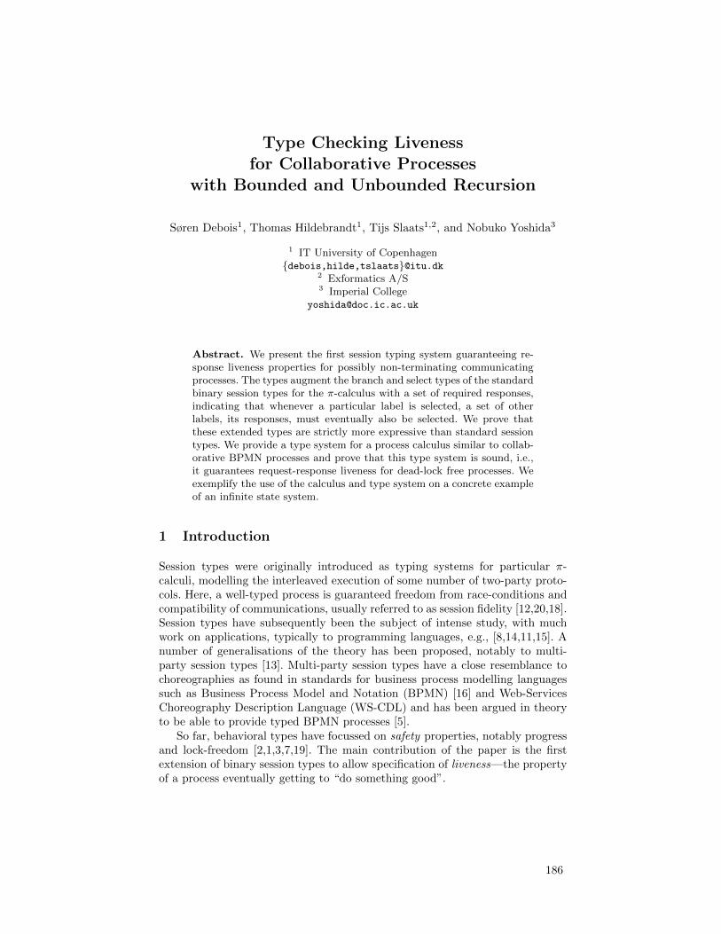
Type Checking Livenessfor Collaborative Processes
with Bounded and Unbounded Recursion
Søren Debois1, Thomas Hildebrandt1, Tijs Slaats1,2, and Nobuko Yoshida3
1 IT University of Copenhagen{debois,hilde,tslaats}@itu.dk
2 Exformatics A/S3 Imperial College
Abstract. We present the first session typing system guaranteeing re-sponse liveness properties for possibly non-terminating communicatingprocesses. The types augment the branch and select types of the standardbinary session types for the π-calculus with a set of required responses,indicating that whenever a particular label is selected, a set of otherlabels, its responses, must eventually also be selected. We prove thatthese extended types are strictly more expressive than standard sessiontypes. We provide a type system for a process calculus similar to collab-orative BPMN processes and prove that this type system is sound, i.e.,it guarantees request-response liveness for dead-lock free processes. Weexemplify the use of the calculus and type system on a concrete exampleof an infinite state system.
1 Introduction
Session types were originally introduced as typing systems for particular π-calculi, modelling the interleaved execution of some number of two-party proto-cols. Here, a well-typed process is guaranteed freedom from race-conditions andcompatibility of communications, usually referred to as session fidelity [12,20,18].Session types have subsequently been the subject of intense study, with muchwork on applications, typically to programming languages, e.g., [8,14,11,15]. Anumber of generalisations of the theory has been proposed, notably to multi-party session types [13]. Multi-party session types have a close resemblance tochoreographies as found in standards for business process modelling languagessuch as Business Process Model and Notation (BPMN) [16] and Web-ServicesChoreography Description Language (WS-CDL) and has been argued in theoryto be able to provide typed BPMN processes [5].
So far, behavioral types have focussed on safety properties, notably progressand lock-freedom [2,1,3,7,19]. The main contribution of the paper is the firstextension of binary session types to allow specification of liveness—the propertyof a process eventually getting to “do something good”.
186

Liveness properties have normally been dealt with by resorting to model-checking techniques (typically requiring a state-space exploration) or dependenttypes explicitly representing bounds of iterations. In the present paper we showthat a common and fundamental class of liveness properties, so-called request-response properties, can be dealt with statically in the type rules, that is, withoutresorting to statespace exploration or the detail (and complexity) of dependenttypes. This means in particular, that we can deal with infinite state systems aswe will exemplify below. Other benefits of the session type-checking approachare that it allows to specify properties as types that can be understood and usedas interface specifications and for compositional reasoning.
We develop the theory in the setting of a process calculus with value pass-ing, conditional branching, external branching and selection, and bounded andunbounded recursion. This calculus corresponds to a core subset of collaborativeBPMN processes with structured loops and bounded iteration, in which both liveand non-live infinite state space BPMN processes can be defined. As a runningexample we use the collaborative shopping cart process shown in Fig. A.
Fig.A. A Potentially Non-live Shopping Cart BPMN Process
The diagram contains two pools: The Buyer and the ShoppingCart. Only thelatter contains a specified process, which consists of two parts: Ordering andDelivery. Ordering is a loop that starts with an event-based gateway, branch-ing according to the message (AddItem, Checkout, RemoveItem) sent by thecustomer: AddItem and RemoveItem messages respectively provides an item tobe added or removed from the order after which the loop repeats. A Checkoutmessage provides delivery details of the order, exits the loop and proceeds to theDelivery part. Delivery is again a loop, delivering the ordered items and thensending the invoice.
A buyer who wants to communicate safely with the Shopping Cart, mustfollow the protocol described above, and in particular be able to receive anunbounded number of items before receiving the invoice. Writing AI,RI,CO,DI,and SI for the actions “Add Items”, ”Remove Items”, “Checkout”, “Deliver
2
187

Items” and “Send Invoice”; we can describe this protocol with a session type:
µt.&{AI.?.t,RI.?.t,CO.?.µt′.⊕ {DI.!.t′,SI.!.end}}
This session type can be regarded as a behavioral interface, specifying that theprocess first expects to receive either an AI (AddItem), RI (RemoveItem) ora CO (CheckOut) event. The two first events must be followed by a message(indicated by ?), which in the implementation provides the item to be addedor removed, after which the protocol returns to the initial state. The checkoutevent is followed by a message (again indicated by a ?) after which the protocolenters a new loop, either sending a DI (DeliverItem) event followed by a message(indicated by a !) and repeating, or sending an SI (SendInvoice) event followedby a message (the invoice) and ending.
However, standard session types can not specify the very relevant livenessproperty, that a CheckOut event is eventually followed by an invoice event. Thisis an example of a so-called response property: an action (the request) must befollowed by a particular response. Thus, we conservatively extend binary sessiontypes to specify such response properties, and we show that this extension isstrictly more expressive than standard session types. We do so by annotatingthe checkout selection in the type with the required response:
µt.&{AI.?.t,RI.?.t,CO[{SI}].?.µt′.⊕ {DI.!.t′,SI.!.end}} .
Intuitively: “if CO is selected, then subsequently also SI must be selected.”
Fig. B. Live delivery with MI Sub-Process
It is not possible to determinefrom the flow graph alone, if this re-sponse property is guaranteed. Thesecond loop may not terminate, e.g.,if the Order is not updated prop-erly when items are sent or the Item-sToSend condition is defined wrongly.However, we can remove this depen-dency on the data if we replace thedelivery loop with a looping primitivewhich is guaranteed to be finite. In BPMN this can be achieved with e.g. theSequential Multiple Instance Sub-process, which sequentially executes a finitenumber (determined by an expression computed at run-time) of instances of asub-process. This allows us to re-define the Delivery as shown in Fig. B, yield-ing a re-defined Shopping Cart process, for which it can be inferred from thestructure of the process that it satisfies the response property. In general, wewant also to be able to check processes where responses are requested within(potentially) infinite loops. The type system we present gives such guarantees,essentially by collecting all requested responses in a forward analysis, exploit-ing that potentially infinite loops can guarantee a particular response only ifevery path through the loop can; and that order (request-response vs response-request) is in this case irrelevant. We prove that, if the system is lock free, then
3
188
the typing system indeed guarantees that all requested responses are eventuallyfulfilled. Lock-freedom is needed because as is well known, collaborative processeswith interleaved sessions may introduce dependency locks. Lock-freedom is well-studied for binary session types [2,1,3,7,19], or may alternatively be achieved byresorting to global types [13], the combination with which we leave for futurework. In summary, our contributions are as follows.
– We extend binary session types with a notion of required response. Thisallows types to express that whenever a particular pattern of communicationis chosen (a label selected in branch/select), that choice must subsequentlybe followed by a particular other choice, its required response.
– We prove that this extension induces a strictly more expressive languageclass than standard session types.
– We give a typing system conservatively extending standard binary sessiontypes which gives the further guarantee that a lock-free well-typed processwill, in any execution, provide all its required responses.
– We exemplify the use of these extended types to guarantee both safety andliveness properties for a non-trivial, infinite state collaborative process, whichexhibits both possibly infinite looping and bounded iteration.
Overview of this paper. In Sec. 2 we define our calculus and introduce a shop-ping cart process which will serve as a running example; in Sec. 3 we give anLTS-semantics for the calculus. In Sec. 4 extend binary session types to allowspecification of response liveness properties, give a transition semantics for thetypes, and sketch a proof that these extended types induce a strictly larger classof languages than does standard binary session types. In Sec. 5 we define ex-actly how our extended session types induce a notion of liveness on processes.In Sec. 6 we give our extended typing rules for sessions with responses and stateits subject reduction result. In Sec. 7 we prove that the extended typing rulesguarantees liveness for lock-free processes. Finally, in Sec. 8 we conclude. Forwant of space, this paper omits details and proofs; for these, refer to [4].
2 Process Terms
Processes communicate only via named communication (session) channels bysynchronizing send and receive actions or synchronizing select and branch events(as in standard session typed π-calculus). The session typing rules presented inthe next session guarantees that there is always at most one active send andreceive action for a given channel. To distinguish dual ends of communicationchannels, we employ polarised names [10,20]: If c is a channel name, c+ and c−
are the dual ends of the channel c. We call these polarised channel names, with“+” and “-” polarities. If k is a polarised channel name, we write k for its dual,e.g., c+ = c−. In general c ranges or channel names; p over polarities +,−; k, hover polarised channel names; x over data variables; i over recursion variables(explained below); v over data values including numbers, strings and booleans;
4
189
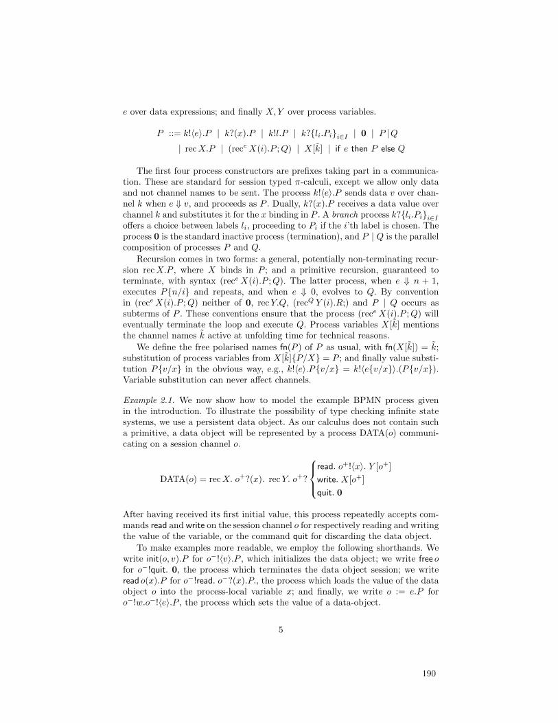
e over data expressions; and finally X,Y over process variables.
P ::= k!〈e〉.P | k?(x).P | k!l.P | k?{li.Pi}i∈I | 0 | P |Q| recX.P | (receX(i).P ;Q) | X[k] | if e then P else Q
The first four process constructors are prefixes taking part in a communica-tion. These are standard for session typed π-calculi, except we allow only dataand not channel names to be sent. The process k!〈e〉.P sends data v over chan-nel k when e ⇓ v, and proceeds as P . Dually, k?(x).P receives a data value overchannel k and substitutes it for the x binding in P . A branch process k?{li.Pi}i∈Ioffers a choice between labels li, proceeding to Pi if the i’th label is chosen. Theprocess 0 is the standard inactive process (termination), and P | Q is the parallelcomposition of processes P and Q.
Recursion comes in two forms: a general, potentially non-terminating recur-sion recX.P , where X binds in P ; and a primitive recursion, guaranteed toterminate, with syntax (receX(i).P ;Q). The latter process, when e ⇓ n + 1,executes P{n/i} and repeats, and when e ⇓ 0, evolves to Q. By conventionin (receX(i).P ;Q) neither of 0, recY.Q, (recQ Y (i).R;) and P | Q occurs assubterms of P . These conventions ensure that the process (receX(i).P ;Q) willeventually terminate the loop and execute Q. Process variables X[k] mentionsthe channel names k active at unfolding time for technical reasons.
We define the free polarised names fn(P ) of P as usual, with fn(X[k]) = k;substitution of process variables from X[k]{P/X} = P ; and finally value substi-tution P{v/x} in the obvious way, e.g., k!〈e〉.P{v/x} = k!〈e{v/x}〉.(P{v/x}).Variable substitution can never affect channels.
Example 2.1. We now show how to model the example BPMN process givenin the introduction. To illustrate the possibility of type checking infinite statesystems, we use a persistent data object. As our calculus does not contain sucha primitive, a data object will be represented by a process DATA(o) communi-cating on a session channel o.
DATA(o) = recX. o+?(x). recY. o+?
read. o+!〈x〉. Y [o+]
write. X[o+]
quit. 0
After having received its first initial value, this process repeatedly accepts com-mands read and write on the session channel o for respectively reading and writingthe value of the variable, or the command quit for discarding the data object.
To make examples more readable, we employ the following shorthands. Wewrite init(o, v).P for o−!〈v〉.P , which initializes the data object; we write free ofor o−!quit. 0, the process which terminates the data object session; we writeread o(x).P for o−!read. o−?(x).P., the process which loads the value of the dataobject o into the process-local variable x; and finally, we write o := e.P foro−!w.o−!〈e〉.P , the process which sets the value of a data-object.
5
190

The shopping cart process can then be modelled as
P (Q) = DATA(o) | init(o, ε). recX.k
AI. k?(x). read o(y). o := add(y, x). X[ko−]
RI. k?(x). read o(y). o := rem(y, x). X[ko−]
CO. k?(x). read o(y). o := add(y, x). Q
.
Here k is the session channel for communicating with the customer and o is thesession channel for communicating with the data object modelling order data.We assume our expression language has suitable operators “add” and “rem”,adding an removing items from the order. Finally, the process Q is a stand-infor either the (non live) delivery part of the BPMN process in Fig. A or the livedelivery part shown in Fig. B.
The non-live delivery loop can be represented by the process
D0 = recY. read o(y). if n(y) > 0
{then k!DI. k!〈next(y)〉. o := update(y). Y [ko−]
else k!SI. k!〈inv(y)〉. free o
where n(y) is the integer expression computing from the order y the numberof items to send, next(y), update(y) and inv(y) are, respectively, the the nextitem(s) to be sent; an update of the order to mark that these items have indeedbeen sent; and the invoice from the order. Note that whether or not this processterminates is entirely dependent on the data operations.
The live delivery with the bounded iteration can be represented by a processusing the bounded recursion
D = read o(y). (recn(y) Y (i).
k!DI.read o(y). k!〈pickitem(y, i)〉.Y [ko−];
k!SI. read o(y). k!〈inv(y)〉. free o)
(The second line is the body of the loop; the third line is the continuation.) Herepickitem(y, i) is the expression extracting the ith item from the order y. ut
3 Transition Semantics
We give a labelled transition semantics in Figure C. We assume a total evaluationrelation e ⇓ v. Note the absence of a structural congruence. Transition labels areλ ::= k!v | k?v | k⊕l | k&l | τ | τ : l. We assume τ is neither a channel nora polarised channel, define subj(k!v) = subj(k?v) = subj(k&l) = subj(k ⊕ l) = kand subj(τ) = subj(τ : l) = τ , and τ = τ . We use these rules along withsymmetric rules for [C-ParL] and [C-Com1/2]. Compared to standard CCS orπ semantics, there are two significant changes: (1) In the [C-ParL], a transition λof P is not preserved by parallel if the co-channel of the subject of λ is in P ′; and(2) in prefix rules, the co-name of the subject cannot appear in the continuation.We impose (1) because if the co-channel of the subject of λ is in P ′, then P | P ′
6
191
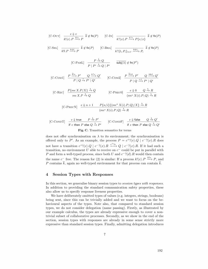
[C-Out]e ⇓ v
k!〈e〉.P k!v−−→ Pk 6∈ fn(P ) [C-In]
k?(x).Pk?v−−→ P{v/x}
k 6∈ fn(P )
[C-Sel]k!l.P
k⊕l−−→ Pk 6∈ fn(P ) [C-Bra]
k?{li.Pi}i∈I k&li−−−→ Pik 6∈ fn(P )
[C-ParL]P
λ−→ Q
P | P ′ λ−→ Q | P ′subj(λ) 6∈ fn(P ′)
[C-Com1]P
k!v−−→ P ′ Qk?v−−→ Q′
P | Q τ−→ P ′ | Q′[C-Com2]
Pk⊕l−−→ P ′ Q
k&l−−→ Q′
P | Q τ :l−−→ P ′ | Q′
[C-Rec]P{recX.P/X} λ−→ Q
recX.Pλ−→ Q
[C-Prec0]e ⇓ 0 Q
λ−→ R
(receX(i).P ;Q)λ−→ R
[C-PrecN]e ⇓ n+ 1 P{n/i}{(recnX(i).P ;Q)/X} λ−→ R
(receX(i).P ;Q)λ−→ R
[C-CondT]e ⇓ true P
λ−→ P ′
if e then P else Qλ−→ P ′
[C-CondF]e ⇓ false Q
λ−→ Q′
if e then P else Qλ−→ Q′
Fig. C. Transition semantics for terms
does not offer synchronisation on λ to its environment; the synchronisation isoffered only to P ′. As an example, the process P = c+!〈v〉.Q | c−?(x).R does
not have a transition c+!〈v〉.Q | c−?(x).Rc+!v−−−→ Q | c−?(x).R. If it had such a
transition, no environment U able to receive on c− could be put in parallel withP and form a well-typed process, since both U and c−?(d).R would then contain
the name c− free. The reason for (2) is similar: If a process k!〈e〉.P k!v−−→ P , andP contains k, again no well-typed environment for that process can contain k.
4 Session Types with Responses
In this section, we generalise binary session types to session types with responses.In addition to providing the standard communication safety properties, thesealso allow us to specify response liveness properties.
We have deliberately omitted types of values (e.g. integers, strings, booleans)being sent, since this can be trivially added and we want to focus on the be-havioural aspects of the types. Note also, that compared to standard sessiontypes, we do not consider delegation (name passing). Firstly, as illustrated byour example calculus, the types are already expressive enough to cover a non-trivial subset of collaborative processes. Secondly, as we show in the end of thesection, session types with responses are already in some sense strictly moreexpressive than standard session types. Finally, admitting delegation introduces
7
192

some non-trivial challenges and choices with respect to how to define and guar-antee liveness, which we have left for future work.
We first define request/response liveness in the abstract. In general, we shalltake it to be the property that “a request is eventually followed by a response”.
Definition 4.1. A request/response structure is a tuple (A,R, req, res) where Ais a set of actions, R is a set of responses, and req : A→ R and res : A→ R aremaps defining the set of responses requested respectively performed by an action.
Notation. We write ε for the empty string, we let φ, ψ range over finite strings,and we let α, β, γ range over finite or infinite sequences. We write sequenceconcatenation by juxtaposition, i.e., φα.
Definition 4.2. Suppose (A,R, req, res) is a request/response structure and α asequence over A. Then the responses res(α) of α is defined by res(α) = ∪{res(a) |∃ϕ, β. α = ϕaβ}. Moreover, α is live iff α = φaβ =⇒ req(a) ⊆ res(β).
Definition 4.3 (LTS with requests/responses). Let (S,L,−→) be an LTS.When the set of labels L is the set of actions of a request/response structure,we say that (S,L,−→) is an LTS with requests/responses, and that a transitionsequence of this LTS is live when its underlying sequence of labels is.
Next, the syntax of session types with responses. Let l range over labels and Lsets of labels.
S, T ::= &{li[Li].Ti}i∈I | ⊕{li[Li].Ti}i∈I | !.T | ?.T | µt.T | t | end
By convention, the li in each &{li[Li].Ti}i∈I resp. ⊕{li[Li].Ti}i∈I are distinct.A session type is a (possibly infinite) tree of actions permitted for one partner
of a two-party communication. The type &{li[Li].Ti}i∈I , called branch, is thetype of offering a choice between different continuations. If the partner choosesthe label li, the session proceeds as Ti. Compared to standard session types,making the choice li also requests a subsequent response on every label mentionedin the set of labels Li; we formalise this in the notion of responsive trace below.Dual to branch is select ⊕{li[Li].Ti}i∈I : the type of making a choice betweendifferent continuations. Like branch, making a choice li requests every labelin Li as future responses. The type !.T and ?.T are the types of sending andreceiving data values. Note that unlike standard session types, channels cannotbe communicated. Finally, session types with responses include recursive types.We take the equi-recursive view, identifying a type T and its unfolding into apotentially infinite tree. We define the central notion of duality between typesas the symmetric relation induced coinductively by the following rules.
end ./ end
T ./ T ′
!.T ./ ?.T ′Ti ./ T
′i J ⊆ I
&{li[Li].Ti}i∈I ./ ⊕{lj [L′j ].T ′j}j∈J(1)
The first rule says that the dual processes agree on when communication stops.The second says that if a process sends a message its dual must receive. Finally,
8
193
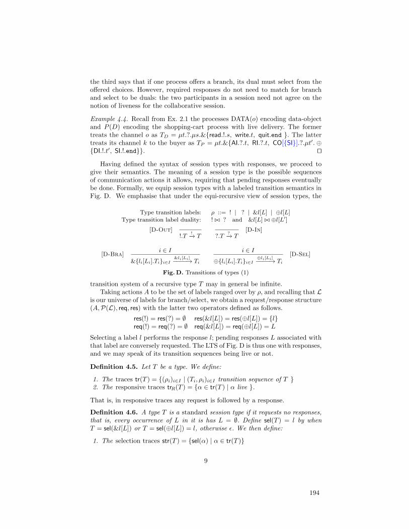
the third says that if one process offers a branch, its dual must select from theoffered choices. However, required responses do not need to match for branchand select to be duals: the two participants in a session need not agree on thenotion of liveness for the collaborative session.
Example 4.4. Recall from Ex. 2.1 the processes DATA(o) encoding data-objectand P (D) encoding the shopping-cart process with live delivery. The formertreats the channel o as TD = µt.?.µs.&{read.!.s, write.t, quit.end }. The lattertreats its channel k to the buyer as TP = µt.&{AI.?.t, RI.?.t, CO[{SI}].?.µt′. ⊕{DI.!.t′, SI.!.end}}. ut
Having defined the syntax of session types with responses, we proceed togive their semantics. The meaning of a session type is the possible sequencesof communication actions it allows, requiring that pending responses eventuallybe done. Formally, we equip session types with a labeled transition semantics inFig. D. We emphasise that under the equi-recursive view of session types, the
Type transition labels: ρ ::= ! | ? | &l[L] | ⊕l[L]Type transition label duality: ! ./ ? and &l[L] ./ ⊕l[L′]
[D-Out]!.T
!−→ T ?.T?−→ T
[D-In]
[D-Bra]i ∈ I
&{li[Li].Ti}i∈I &li[Li]−−−−→ Ti
i ∈ I⊕{li[Li].Ti}i∈I ⊕li[Li]−−−−→ Ti
[D-Sel]
Fig.D. Transitions of types (1)
transition system of a recursive type T may in general be infinite.Taking actions A to be the set of labels ranged over by ρ, and recalling that L
is our universe of labels for branch/select, we obtain a request/response structure(A,P(L), req, res) with the latter two operators defined as follows.
res(!) = res(?) = ∅ res(&l[L]) = res(⊕l[L]) = {l}req(!) = req(?) = ∅ req(&l[L]) = req(⊕l[L]) = L
Selecting a label l performs the response l; pending responses L associated withthat label are conversely requested. The LTS of Fig. D is thus one with responses,and we may speak of its transition sequences being live or not.
Definition 4.5. Let T be a type. We define:
1. The traces tr(T ) = {(ρi)i∈I | (Ti, ρi)i∈I transition sequence of T }2. The responsive traces trR(T ) = {α ∈ tr(T ) | α live }.
That is, in responsive traces any request is followed by a response.
Definition 4.6. A type T is a standard session type if it requests no responses,that is, every occurrence of L in it is has L = ∅. Define sel(T ) = l by whenT = sel(&l[L]) or T = sel(⊕l[L]) = l, otherwise ε. We then define:
1. The selection traces str(T ) = {sel(α) | α ∈ tr(T )}
9
194
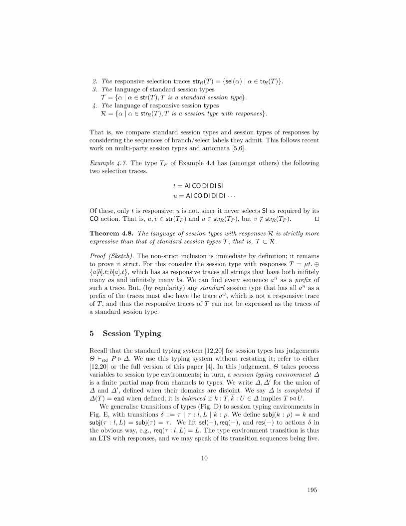
2. The responsive selection traces strR(T ) = {sel(α) | α ∈ trR(T )}.3. The language of standard session typesT = {α | α ∈ str(T ), T is a standard session type}.
4. The language of responsive session typesR = {α | α ∈ strR(T ), T is a session type with responses}.
That is, we compare standard session types and session types of responses byconsidering the sequences of branch/select labels they admit. This follows recentwork on multi-party session types and automata [5,6].
Example 4.7. The type TP of Example 4.4 has (amongst others) the followingtwo selection traces.
t = AI CODIDI SI
u = AI CODIDIDI · · ·
Of these, only t is responsive; u is not, since it never selects SI as required by itsCO action. That is, u, v ∈ str(TP ) and u ∈ strR(TP ), but v 6∈ strR(TP ). ut
Theorem 4.8. The language of session types with responses R is strictly moreexpressive than that of standard session types T ; that is, T ⊂ R.
Proof (Sketch). The non-strict inclusion is immediate by definition; it remainsto prove it strict. For this consider the session type with responses T = µt. ⊕{a[b].t; b[a].t}, which has as responsive traces all strings that have both inifitelymany as and infinitely many bs. We can find every sequence an as a prefix ofsuch a trace. But, (by regularity) any standard session type that has all an as aprefix of the traces must also have the trace aω, which is not a responsive traceof T , and thus the responsive traces of T can not be expressed as the traces ofa standard session type.
5 Session Typing
Recall that the standard typing system [12,20] for session types has judgementsΘ `std P . ∆. We use this typing system without restating it; refer to either[12,20] or the full version of this paper [4]. In this judgement, Θ takes processvariables to session type environments; in turn, a session typing environment ∆is a finite partial map from channels to types. We write ∆,∆′ for the union of∆ and ∆′, defined when their domains are disjoint. We say ∆ is completed if∆(T ) = end when defined; it is balanced if k : T, k : U ∈ ∆ implies T ./ U .
We generalise transitions of types (Fig. D) to session typing environments inFig. E, with transitions δ ::= τ | τ : l, L | k : ρ. We define subj(k : ρ) = k andsubj(τ : l, L) = subj(τ) = τ . We lift sel(−), req(−), and res(−) to actions δ inthe obvious way, e.g., req(τ : l, L) = L. The type environment transition is thusan LTS with responses, and we may speak of its transition sequences being live.
10
195

[E-Lift]T
ρ−→ T ′
k : Tk:ρ−−→ k : T ′
[E-Par]∆
δ−→ ∆′
∆,∆′′δ−→ ∆′,∆′′
[E-Com1]∆1
k:!−→ ∆′1 ∆2k:?−−→ ∆′2
∆1,∆2τ−→ ∆′1,∆
′2
[E-Com2]∆1
k:⊕l[L]−−−−→ ∆′1 ∆2k:&l[L′]−−−−−→ ∆′2
∆1,∆2τ :l,L∪L′−−−−−→ ∆′1,∆
′2
Fig. E. Transitions of types (2)
Definition 5.1. We define a binary relation on type transition labels δ andtransition labels λ, written δ ' λ, as follows.
τ ' τ k : &l[L] ' k&l k : ! ' k!v
τ : l, L ' τ : l k : ⊕l[L] ' k ⊕ l k : ? ' k?x
Theorem 5.2. If Γ `std P .∆ and Pλ−→ Q, then there exists δ ' λ s.t. ∆
δ−→ ∆′
and Γ `std Q . ∆′.
Definition 5.3. The typed transition system is the transition system which has
states Γ `std P . ∆ and transitions Γ `std P . ∆λ,δ−−→ Γ `std P ′ . ∆′ whenever
there exist transitions Pλ−→ P ′ and ∆
δ−→ ∆′ with δ ' λ.
We can now say what it means for a process to be live.
Definition 5.4 (Live process). A well-typed process Θ `std P .∆ is live wrt.Θ,∆ iff for any maximal transition sequence (Pi, λi)i of P there exists a livetype transition sequence (∆i, δi)i of ∆ s.t. ((Pi, ∆i), (λi, δi))i is a typed transitionsequence of Θ `std P . ∆.
Example 5.5. Wrt. the standard session typing system, both of the processesP (D0) and P (D) of Example 2.1 are typable wrt. the types we postulated forthem in Example 4.4. Specifically, we have · `std P (D0) . k : TP , o
+ : TD, o− :
TD and similarly P (D). The judgement means that the process P (D) treats kaccording to TP and the (two ends of) the data object according to TD andits dual TD. The standard session typing system of course does not act on ourliveness annotations, and so does not care that P (D0) is not live.
6 Typing system for liveness
We now give our extended typing system for session types with responses. Thecentral judgement will be Γ ;L ` P . ∆, with the intended meaning that “withprocess variables Γ and pending responses L, the process P conforms to ∆.”We shall see in the next section that a well-typed lock-free P is live and willeventually perform every response in in L. We need:
1. Session typing environments ∆ defined at the start of Section 5.2. Response environments L are simply sets of branch/select labels.
11
196

3. Process variable environments Γ are finite partial maps from process vari-ables X to tuples (L,L,∆) or (L,∆). We write these (A, I,∆) for (A)ccumu-lated selections and request (I)nvariant. We define (Γ+L)(X) = (A∪L, I,∆)when Γ (X) = (A, I,∆) and Γ (X) otherwise, writing Γ+l instead of Γ+{l}.
The liveness-guaranteeing type systems is in Fig. F. We explain the rules; first,
[F-Out]Γ ;L ` P . ∆, k : T
Γ ;L ` k!〈e〉.P . ∆, k : !.T[F-In]
Γ ;L ` P . ∆, k : T
Γ ;L ` k?(x).P . ∆, k : ?.T
[F-Bra]∀i ∈ I : Γ + li; (L \ li) ∪ Li ` Pi . ∆, k : TiΓ ;L ` k?{li.Pi}i∈I . ∆, k : &{li[Li].Ti}i∈I
[F-Sel]Γ + lj ; (L \ lj) ∪ Lj ` P . ∆, k : TjΓ ;L ` k!lj .P . ∆, k : ⊕{li[Li].Ti}i∈I
(j ∈ I)
[F-Par]Γ ;L1 ` P1 . ∆1 Γ ;L2 ` P2 . ∆2
Γ ;L1 ∪ L2 ` P1 | P2 . ∆1,∆2[F-Inact]
∆ completed
Γ ; ∅ ` 0 . ∆
[F-Var]L ⊆ I ⊆ A dom(∆) = k
Γ,X : (A, I,∆);L ` X[k] . ∆[F-VarP]
L ⊆ L′ dom(∆) = k
Γ,X : (L′,∆);L ` X[k] . ∆
[F-RecP]Γ,X : (L′,∆);L′ ` P . ∆ Γ ;L′ ` Q . ∆ L ⊆ L′
Γ ;L ` (receX(i).P ;Q) . ∆
[F-Rec]Γ,X : (∅, I,∆); I ` P . ∆ L ⊆ I
Γ ;L ` recX.P . ∆[F-Cond]
Γ ;L ` P . ∆ Γ ;L ` Q . ∆
Γ ;L ` if e then P else Q . ∆Fig. F. Typing System
branch/select, rules [F-Bra]/[F-Sel]. To type k!l.P wrt. k : ⊕l[L′].T , we mustverify that P performs every response in L′. We maintain an environment Lof currently pending responses for this. In the hypothesis, when typing P , weadd the new pending responses L′. But selecting l performs the response l, soaltogether, to support pending responses L in the conclusion, we must havepending responses L \ {l} ∪ L′ in the hypothesis. Branching is similar.
For finite processes, if the inactive process must be typed with the emptyrequest environment, liveness is ensured. Hence in the rule 0, the pending re-sponses environment is required to be empty. For infinite processes there is noparticular point at which we can insist there is no pending responses. ConsiderrecX.k ⊕ a. k ⊕ b. X[k] typeable under k : µt.⊕ {a[b].t; b[a].t}. This process has
the single transition sequence Pk⊕a−−−→ k ⊕ b. P k⊕b−−→ P
k⊕a−−−→ · · ·. At each statebut the initial one, the process has a pending response: in states P it needs torespond b; in states k ⊕ b. P it needs to respond a. Yet the process is live: anyresponse requested in the body of the recursion is also discharged in the body,although not necessarily in the proper order. In general, infinite behaviour arises
12
197

because of unfolding of recursion, so if the body of every recursion dischargesthe requests of that body, even if not in the proper order, responses are ensured.
For general recursion, [F-Rec] and [F-Var], we need to check that thereexists an invariant, a set of responses, such that the body of a recursion requestsat most that set, and reponds with at least that set. In the process variableenvironment Γ we record this response invariant for each variable, along with atally of the responses performed since the start of the recursion. That tally isthen updated by the rules [F-Sel]/[F-Bra] for select and branch. The rule forprocess variable [F-Var] typing then check that the tally includes the invariant,and that the invariant includes every currently pending response.
Definition 6.1. We define the standard process variable environment std(Γ )associated with a process variable environment Γ std(Γ )(X) = ∆ when Γ (X) =(A, I,∆) or Γ (X) = ∆.
Theorem 6.2. If Γ ;L ` P . ∆ then also std(Γ ) `std P . ∆.
Theorem 6.3 (Subject reduction). Suppose that ·;L ` P .∆ with and Pλ−→
Q. Then there exists a type transition ∆δ−→ ∆′ with δ ' λ, such that ·; (L \
res(δ)) ∪ req(δ) ` Q . ∆′. Moreover, if ∆ balanced then also ∆′ balanced.
Example 6.4. Wrt. the typing system of Figure F, the process P (D) is typablewrt. the types we postulated for it in Example 4.4. The process P (D0) on theother hand is not. That is, we have ·; ∅ ` P (D) . k : TP , o
+ : TD, o− : TD, but
the same does not hold for P (D0).We also exemplify a typing judgment with non-trivial guaranteed responses.
The process D, the order-fulfillment part of P (D), can in fact be typed
·; {SI} ` D . k : µt′.⊕{DI.!.t′,SI.!.end}, o− : TD
The interesting bit is the left-most {SI}, indicating intuitively that this processwill eventually select SI in any execution. If you look back at the actual processD in Example 2.1, you will see that D has this property precisely because itimplements a bounded recursion.
7 Liveness
We prove that a lock-free process well-typed under our liveness typing systemis indeed live under fair executions. For defining lock-freedom and fairness, wemust track occurrences of prefixes across transitions. This is straightforward inthe absence of a structural congruence; refer to [9] for a formal treatment.
Definition 7.1. A prefix M is a process on one of the forms k!〈e〉.P , k?(x).P ,k?{li.Pi}, or k!l.P . An occurence of a prefix M in a process P is a path in theabstract syntax tree of P to a subterm on the form M (see [9] for details). An
occurrence of a prefix P in M where Pλ−→ Q is preserved by the latter if M has
the same occurrence in Q; executed otherwise. It is enabled if it is executed bysome transition, and top-level if it is not nested in another prefix.
13
198
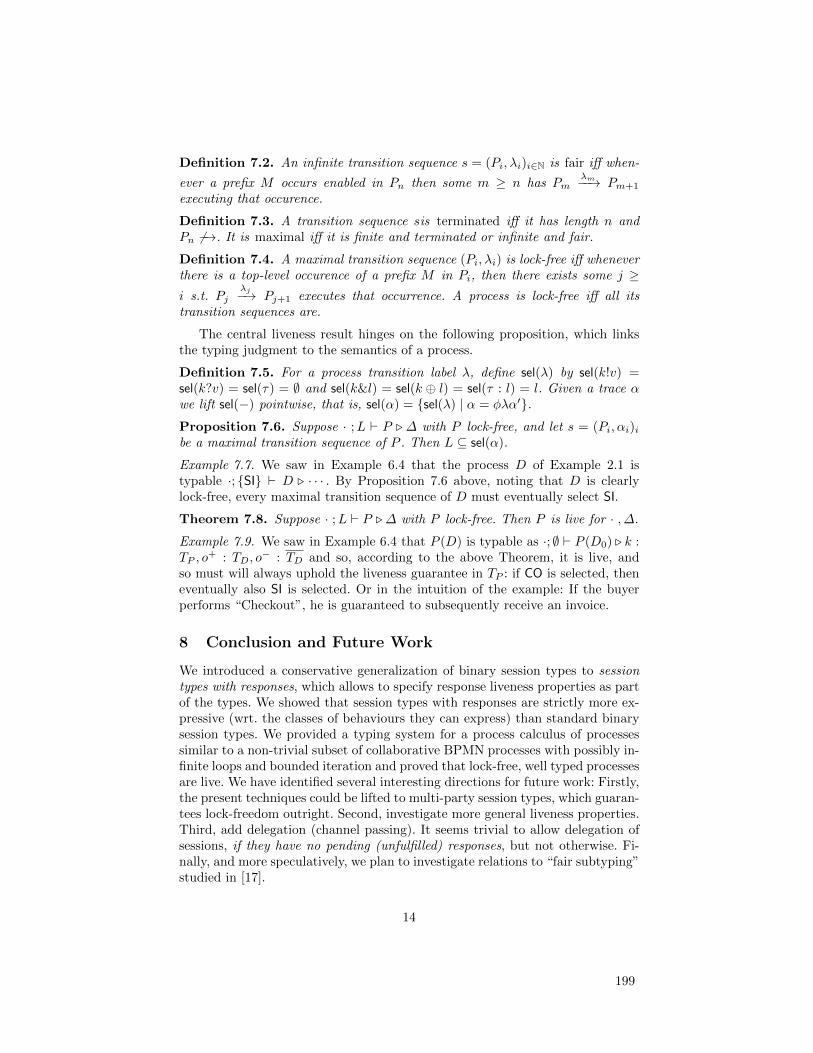
Definition 7.2. An infinite transition sequence s = (Pi, λi)i∈N is fair iff when-
ever a prefix M occurs enabled in Pn then some m ≥ n has Pmλm−−→ Pm+1
executing that occurence.
Definition 7.3. A transition sequence sis terminated iff it has length n andPn 6−→. It is maximal iff it is finite and terminated or infinite and fair.
Definition 7.4. A maximal transition sequence (Pi, λi) is lock-free iff wheneverthere is a top-level occurence of a prefix M in Pi, then there exists some j ≥i s.t. Pj
λj−→ Pj+1 executes that occurrence. A process is lock-free iff all itstransition sequences are.
The central liveness result hinges on the following proposition, which linksthe typing judgment to the semantics of a process.
Definition 7.5. For a process transition label λ, define sel(λ) by sel(k!v) =sel(k?v) = sel(τ) = ∅ and sel(k&l) = sel(k ⊕ l) = sel(τ : l) = l. Given a trace αwe lift sel(−) pointwise, that is, sel(α) = {sel(λ) | α = φλα′}.Proposition 7.6. Suppose · ;L ` P . ∆ with P lock-free, and let s = (Pi, αi)ibe a maximal transition sequence of P . Then L ⊆ sel(α).
Example 7.7. We saw in Example 6.4 that the process D of Example 2.1 istypable ·; {SI} ` D . · · · . By Proposition 7.6 above, noting that D is clearlylock-free, every maximal transition sequence of D must eventually select SI.
Theorem 7.8. Suppose · ;L ` P . ∆ with P lock-free. Then P is live for · , ∆.
Example 7.9. We saw in Example 6.4 that P (D) is typable as ·; ∅ ` P (D0) . k :TP , o
+ : TD, o− : TD and so, according to the above Theorem, it is live, and
so must will always uphold the liveness guarantee in TP : if CO is selected, theneventually also SI is selected. Or in the intuition of the example: If the buyerperforms “Checkout”, he is guaranteed to subsequently receive an invoice.
8 Conclusion and Future Work
We introduced a conservative generalization of binary session types to sessiontypes with responses, which allows to specify response liveness properties as partof the types. We showed that session types with responses are strictly more ex-pressive (wrt. the classes of behaviours they can express) than standard binarysession types. We provided a typing system for a process calculus of processessimilar to a non-trivial subset of collaborative BPMN processes with possibly in-finite loops and bounded iteration and proved that lock-free, well typed processesare live. We have identified several interesting directions for future work: Firstly,the present techniques could be lifted to multi-party session types, which guaran-tees lock-freedom outright. Second, investigate more general liveness properties.Third, add delegation (channel passing). It seems trivial to allow delegation ofsessions, if they have no pending (unfulfilled) responses, but not otherwise. Fi-nally, and more speculatively, we plan to investigate relations to “fair subtyping”studied in [17].
14
199
References
1. Bettini, L., M. Coppo, L. D’Antoni, M. D. Luca, M. Dezani-Ciancaglini andN. Yoshida, Global progress in dynamically interleaved multiparty sessions, in:CONCUR, 2008, pp. 418–433.
2. Carbone, M. and S. Debois, A graphical approach to progress for structured com-munication in web services, in: ICE, 2010, pp. 13–27.
3. Coppo, M., M. Dezani-Ciancaglini, L. Padovani and N. Yoshida, Inference of globalprogress properties for dynamically interleaved multiparty sessions, in: COORDI-NATION, 2013, pp. 45–59.
4. Debois, S., T. Hildebrandt, T. Slaats and N. Yoshida, Type checking liveness forcollaborative processes with bounded and unbounded recursion (full version).URL http://www.itu.dk/~hilde/liveness-full.pdf
5. Denielou, P.-M. and N. Yoshida, Multiparty session types meet communicating au-tomata, in: ESOP, 2012, pp. 194–213.
6. Denielou, P.-M. and N. Yoshida, Multiparty compatibility in communicating au-tomata: Characterisation and synthesis of global session types, in: ICALP (2), 2013,pp. 174–186.
7. Dezani-Ciancaglini, M., U. de’Liguoro and N. Yoshida, On progress for structuredcommunications, in: TGC, 2007, pp. 257–275.
8. Dezani-Ciancaglini, M., S. Drossopoulou, D. Mostrous and N. Yoshida, Objects andsession types, Inf. Comput. 207 (2009), pp. 595–641.
9. Fossati, L., K. Honda and N. Yoshida, Intensional and extensional characterisationof global progress in the π-calculus, in: CONCUR, 2012, pp. 287–301.
10. Gay, S. J. and M. Hole, Subtyping for session types in the pi calculus, Acta Inf. 42(2005), pp. 191–225.
11. Honda, K., A. Mukhamedov, G. Brown, T.-C. Chen and N. Yoshida, Scribblinginteractions with a formal foundation, in: ICDCIT, 2011, pp. 55–75.
12. Honda, K., V. Vasconcelos and M. Kubo, Language primitives and type disciplinefor structured communication-based programming, in: ESOP, 1998, pp. 122–138.
13. Honda, K., N. Yoshida and M. Carbone, Multiparty asynchronous session types,in: POPL, 2008, pp. 273–284.
14. Hu, R., N. Yoshida and K. Honda, Session-based distributed programming in Java,in: J. Vitek, editor, ECOOP ’08, LNCS 5142, 2008 pp. 516–541.
15. Mostrous, D. and V. T. Vasconcelos, Session typing for a featherweight Erlang, in:COORDINATION, 2011, pp. 95–109.
16. Object Management Group BPMN Technical Committee, Business Process Modeland Notation, v2.0, Webpage (2011), http://www.omg.org/spec/BPMN/2.0/PDF.
17. Padovani, L., Fair subtyping for open session types, in: ICALP (2), 2013, pp. 373–384.
18. Vasconcelos, V., Fundamentals of session types, I&C 217 (2012), pp. 52–70.19. Vieira, H. T. and V. T. Vasconcelos, Typing progress in communication-centred
systems, in: COORDINATION, 2013, pp. 236–250.20. Yoshida, N. and V. T. Vasconcelos, Language primitives and type discipline for
structured communication-based programming revisited: Two systems for higher-order session communication, ENTCS 171 (2007), pp. 73–93.
15
200

7 Safe Runtime Adaptation of Flexible Processes
201
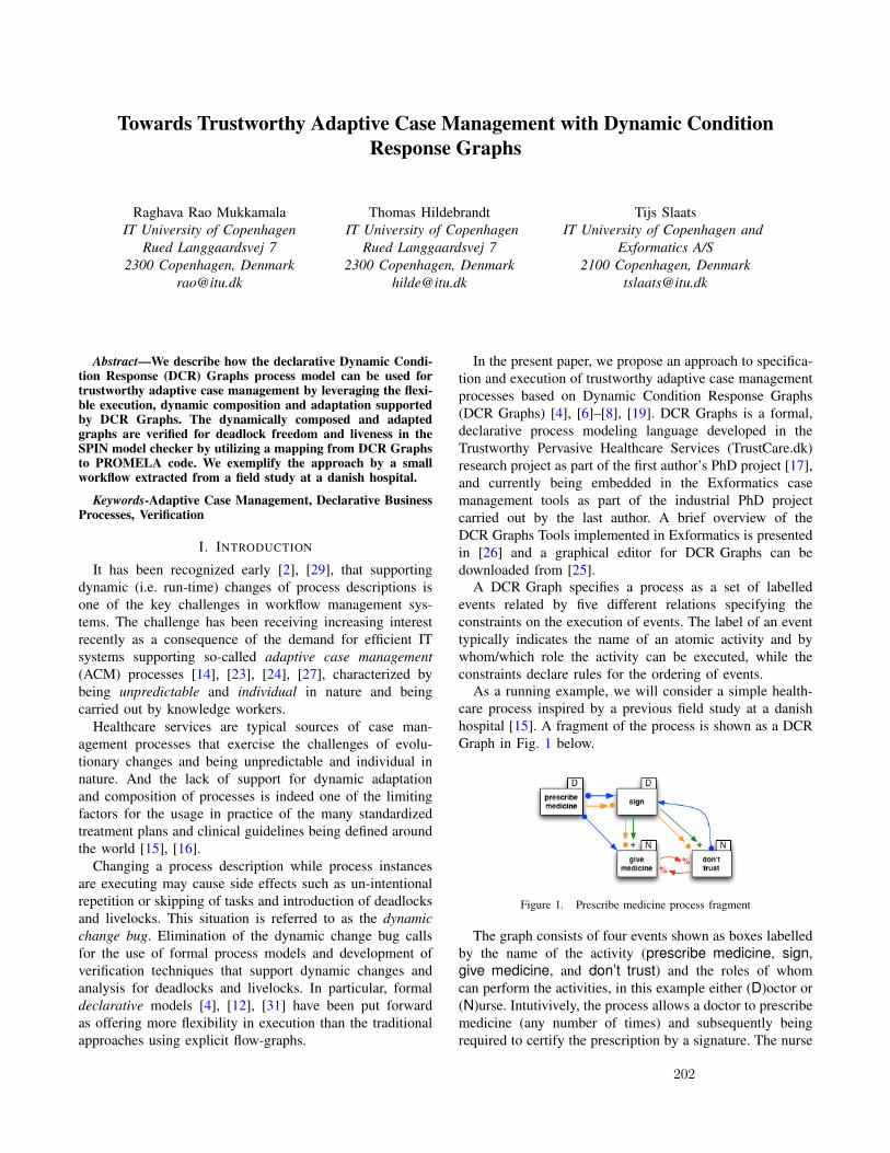
Towards Trustworthy Adaptive Case Management with Dynamic ConditionResponse Graphs
Raghava Rao MukkamalaIT University of Copenhagen
Rued Langgaardsvej 72300 Copenhagen, Denmark
Thomas HildebrandtIT University of Copenhagen
Rued Langgaardsvej 72300 Copenhagen, Denmark
Tijs SlaatsIT University of Copenhagen and
Exformatics A/S2100 Copenhagen, Denmark
Abstract—We describe how the declarative Dynamic Condi-tion Response (DCR) Graphs process model can be used fortrustworthy adaptive case management by leveraging the flexi-ble execution, dynamic composition and adaptation supportedby DCR Graphs. The dynamically composed and adaptedgraphs are verified for deadlock freedom and liveness in theSPIN model checker by utilizing a mapping from DCR Graphsto PROMELA code. We exemplify the approach by a smallworkflow extracted from a field study at a danish hospital.
Keywords-Adaptive Case Management, Declarative BusinessProcesses, Verification
I. INTRODUCTION
It has been recognized early [2], [29], that supportingdynamic (i.e. run-time) changes of process descriptions isone of the key challenges in workflow management sys-tems. The challenge has been receiving increasing interestrecently as a consequence of the demand for efficient ITsystems supporting so-called adaptive case management(ACM) processes [14], [23], [24], [27], characterized bybeing unpredictable and individual in nature and beingcarried out by knowledge workers.
Healthcare services are typical sources of case man-agement processes that exercise the challenges of evolu-tionary changes and being unpredictable and individual innature. And the lack of support for dynamic adaptationand composition of processes is indeed one of the limitingfactors for the usage in practice of the many standardizedtreatment plans and clinical guidelines being defined aroundthe world [15], [16].
Changing a process description while process instancesare executing may cause side effects such as un-intentionalrepetition or skipping of tasks and introduction of deadlocksand livelocks. This situation is referred to as the dynamicchange bug. Elimination of the dynamic change bug callsfor the use of formal process models and development ofverification techniques that support dynamic changes andanalysis for deadlocks and livelocks. In particular, formaldeclarative models [4], [12], [31] have been put forwardas offering more flexibility in execution than the traditionalapproaches using explicit flow-graphs.
In the present paper, we propose an approach to specifica-tion and execution of trustworthy adaptive case managementprocesses based on Dynamic Condition Response Graphs(DCR Graphs) [4], [6]–[8], [19]. DCR Graphs is a formal,declarative process modeling language developed in theTrustworthy Pervasive Healthcare Services (TrustCare.dk)research project as part of the first author’s PhD project [17],and currently being embedded in the Exformatics casemanagement tools as part of the industrial PhD projectcarried out by the last author. A brief overview of theDCR Graphs Tools implemented in Exformatics is presentedin [26] and a graphical editor for DCR Graphs can bedownloaded from [25].
A DCR Graph specifies a process as a set of labelledevents related by five different relations specifying theconstraints on the execution of events. The label of an eventtypically indicates the name of an atomic activity and bywhom/which role the activity can be executed, while theconstraints declare rules for the ordering of events.
As a running example, we will consider a simple health-care process inspired by a previous field study at a danishhospital [15]. A fragment of the process is shown as a DCRGraph in Fig. 1 below.
Figure 1. Prescribe medicine process fragment
The graph consists of four events shown as boxes labelledby the name of the activity (prescribe medicine, sign,give medicine, and don’t trust) and the roles of whomcan perform the activities, in this example either (D)octor or(N)urse. Intutivively, the process allows a doctor to prescribemedicine (any number of times) and subsequently beingrequired to certify the prescription by a signature. The nurse
202
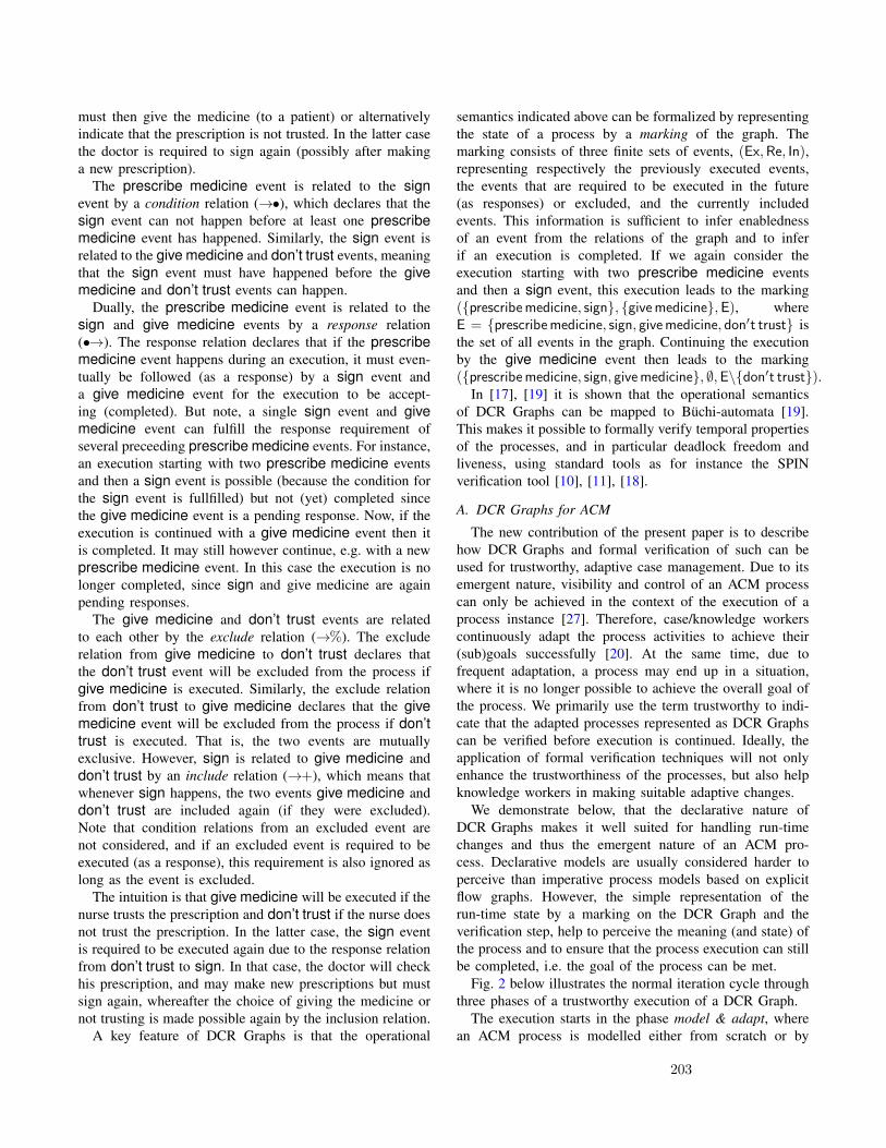
must then give the medicine (to a patient) or alternativelyindicate that the prescription is not trusted. In the latter casethe doctor is required to sign again (possibly after makinga new prescription).
The prescribe medicine event is related to the signevent by a condition relation (→•), which declares that thesign event can not happen before at least one prescribemedicine event has happened. Similarly, the sign event isrelated to the give medicine and don’t trust events, meaningthat the sign event must have happened before the givemedicine and don’t trust events can happen.
Dually, the prescribe medicine event is related to thesign and give medicine events by a response relation(•→). The response relation declares that if the prescribemedicine event happens during an execution, it must even-tually be followed (as a response) by a sign event anda give medicine event for the execution to be accept-ing (completed). But note, a single sign event and givemedicine event can fulfill the response requirement ofseveral preceeding prescribe medicine events. For instance,an execution starting with two prescribe medicine eventsand then a sign event is possible (because the condition forthe sign event is fullfilled) but not (yet) completed sincethe give medicine event is a pending response. Now, if theexecution is continued with a give medicine event then itis completed. It may still however continue, e.g. with a newprescribe medicine event. In this case the execution is nolonger completed, since sign and give medicine are againpending responses.
The give medicine and don’t trust events are relatedto each other by the exclude relation (→%). The excluderelation from give medicine to don’t trust declares thatthe don’t trust event will be excluded from the process ifgive medicine is executed. Similarly, the exclude relationfrom don’t trust to give medicine declares that the givemedicine event will be excluded from the process if don’ttrust is executed. That is, the two events are mutuallyexclusive. However, sign is related to give medicine anddon’t trust by an include relation (→+), which means thatwhenever sign happens, the two events give medicine anddon’t trust are included again (if they were excluded).Note that condition relations from an excluded event arenot considered, and if an excluded event is required to beexecuted (as a response), this requirement is also ignored aslong as the event is excluded.
The intuition is that give medicine will be executed if thenurse trusts the prescription and don’t trust if the nurse doesnot trust the prescription. In the latter case, the sign eventis required to be executed again due to the response relationfrom don’t trust to sign. In that case, the doctor will checkhis prescription, and may make new prescriptions but mustsign again, whereafter the choice of giving the medicine ornot trusting is made possible again by the inclusion relation.
A key feature of DCR Graphs is that the operational
semantics indicated above can be formalized by representingthe state of a process by a marking of the graph. Themarking consists of three finite sets of events, (Ex,Re, In),representing respectively the previously executed events,the events that are required to be executed in the future(as responses) or excluded, and the currently includedevents. This information is sufficient to infer enablednessof an event from the relations of the graph and to inferif an execution is completed. If we again consider theexecution starting with two prescribe medicine eventsand then a sign event, this execution leads to the marking({prescribemedicine, sign}, {givemedicine},E), whereE = {prescribemedicine, sign, givemedicine, don′t trust} isthe set of all events in the graph. Continuing the executionby the give medicine event then leads to the marking({prescribemedicine, sign, givemedicine}, ∅,E\{don′t trust}).
In [17], [19] it is shown that the operational semanticsof DCR Graphs can be mapped to Buchi-automata [19].This makes it possible to formally verify temporal propertiesof the processes, and in particular deadlock freedom andliveness, using standard tools as for instance the SPINverification tool [10], [11], [18].
A. DCR Graphs for ACM
The new contribution of the present paper is to describehow DCR Graphs and formal verification of such can beused for trustworthy, adaptive case management. Due to itsemergent nature, visibility and control of an ACM processcan only be achieved in the context of the execution of aprocess instance [27]. Therefore, case/knowledge workerscontinuously adapt the process activities to achieve their(sub)goals successfully [20]. At the same time, due tofrequent adaptation, a process may end up in a situation,where it is no longer possible to achieve the overall goal ofthe process. We primarily use the term trustworthy to indi-cate that the adapted processes represented as DCR Graphscan be verified before execution is continued. Ideally, theapplication of formal verification techniques will not onlyenhance the trustworthiness of the processes, but also helpknowledge workers in making suitable adaptive changes.
We demonstrate below, that the declarative nature ofDCR Graphs makes it well suited for handling run-timechanges and thus the emergent nature of an ACM pro-cess. Declarative models are usually considered harder toperceive than imperative process models based on explicitflow graphs. However, the simple representation of therun-time state by a marking on the DCR Graph and theverification step, help to perceive the meaning (and state) ofthe process and to ensure that the process execution can stillbe completed, i.e. the goal of the process can be met.
Fig. 2 below illustrates the normal iteration cycle throughthree phases of a trustworthy execution of a DCR Graph.
The execution starts in the phase model & adapt, wherean ACM process is modelled either from scratch or by
203

Figure 2. Execution phases of a DCR Graph for ACM
selecting one or more DCR Graphs process fragments (e.g.provided in repositories) which are composed and adapted.In dynamic environments, process knowledge can be localand fragmentary, confined to a certain situation or context.Process Fragments [1] represent a notion of partial andlocal knowledge, which can be integrated or composeddynamically at design time or run-time. Adopting the notionof process fragments, DCR Graphs can be used as processfragments to represent a partial perspective of a complexprocess, which can be combined through dynamic compo-sition. Formally speaking, there is no difference between anormal DCR Graph and a DCR Graph representing a pro-cess fragment, except that the fragment DCR Graph mightrepresent a subgoal or partial functionality like reusable tem-plates. Fig 3 shows two such fragments for our healthcareexample, to be explained in Sec. IV.
(a) prescribe medicine (b) order tests
Figure 3. DCR Graph fragments
In the next phase, verify, formal verification techniqueswill be applied to the process. For instance, one could verifythat the process does not allow deadlocks, always allowsprogress and to achieve the overall goal, i.e. completion by(continued) execution or exclusion of all pending responseevents.
After successful verification of the process, the executioncan proceed to the next phase, partial execution, where theprocess can be executed further until it reaches a point where
further adaptation is required and the execution moves tothe model & adapt phase, starting a new iteration. However,note that (in the spirit of ACM) it should also be possibleto go back to the modelling phase after verification, to skipverification after the modelling phase, or go back to theverify phase after the partial execution.
In this way, an ACM process represented as DCR Graphscan be modelled, verified and executed iteratively, wherethe emergence of new knowledge can be used by the caseworkers to adapt the processes at run-time.
However, one may ask why the proposed approach can notsimply prevent adoptions that will lead to dead/livelocks. Webelieve that the general approach allowing to compose/adaptand have intermediate models containing potential deadlock-s/livelocks would be valuable as it gives more flexibilityin the modeling and adaptation phase. It can be seen asanalogous to be able to write a program that does not typecheck, and then correct the errors, as opposed to only beable to add code parts that lead to a well-typed program.
B. Structure of paper
The rest of the paper is structured as follows. We discussrelated work in Sec. II whereas in Sec. III we furtherelaborate the idea of using DCR Graphs for ACM by ourhealthcare example. In Sec. IV we then formally define theadaptation operations on DCR Graphs, after recalling theformal definition of DCR Graphs and their execution. InSec. V we then formally define what it means for a DCRGraph to be deadlocked and live, introducing new notions ofstrongly deadlock free and live processes which guaranteeprogress even if only events that are required as responsesare executed. This is in particular relevant if the executionof the DCR Graphs is distributed on different peers (e.g.according to the different roles) as considered in [7]. InSec. VI we then describe how to verify safety and livenessproperties on DCR Graphs (as defined in Sec. V) usingthe SPIN model checking tool and based on the mappingof DCR Graphs to Buchi-automata [19]. Finally, Sec. VIIconcludes the paper.
II. RELATED WORK
The issue of dynamic change [2] in workflow systemshas been investigated thoroughly for Petri net and graphbased models. In [29] Van der Aalst described an approachto find change regions in WorkFlow nets, which representthe parts of a model that are effected by a change. Healso proved that a change can be safely applied to a partoutside the change region, simultaneously preserving thesoundness of a workflow instance. In [22] Reichert et al.presented a framework for the support of adaptive changesin the graph-based workflow model ADEPT. They developeda complete and minimal set of change operations that willallow for modifying an ADEPT workflow at run-time, whilestill preserving its consistency and correctness.
204

The previous work often take as a correctness criteriain previous approaches [2], [22], [29], that the state of theinstance after applying the change, could have been reachedfrom the initial state by replaying the past run. We findthat only allowing changes that are consistent with the pasthistory too strong for ACM. Instead we advocate recordingthe change as part of the execution sequence.
Recent studies [24], [28] have indicated that BPMN-likelanguages are not suitable for ACM. One reason is that theprocesses are described as procedures. Procedures tend toover-specify the processes, and also, the changes one can ap-ply must be formulated as changes to the procedure. On theother hand, declarative workflow models [4], [12], [23], [31],including DCR Graphs, have been proposed as a alternativeto traditional workflow models to handle unpredictabilityand emergent nature of ACM processes. Here process aredescribed by declaring the constraints and goals, whichusually under-specify the process and supports changes tothe constraints and goals. Declare [30] is a constraint-based declarative workflow model formalized using lineartime logic (LTL). Similar to DCR Graphs, Declare alsosupports adaptive changes such as add/remove constraintsand activities, however, since they can not be interpreted inan immediate state, it is required that the trace of the pastexecution satisfies the LTL formulae corresponding to thechange. That is, as discussed above, only changes that areconsistent with the run so far are allowed.
A declarative approach using Guard-Stage-Milestone [12]based on ECA-like rules for specification of life cycleson Business artifacts was proposed in the recent years. Tothe best of our knowledge, no work on adaptive changesfor the GSM model has been published yet. However, ithas been advocated as a model for ACM due to its richdata-centric approach and declarative nature and forms thebasis for the recent Case Management Model And Notation(CMMN) [21] proposed by OMG, which includes supportfor dynamic changes. Also the IBM case manger [3] in-cludes some support for dynamic changes. Furthermore,a modeling approach based on Declarative ConfigurableProcess Specifications [24] is being developed for automatedsupport of case management processes. Using declarativemodeling, their model supports process adaptability by usingconfigurable data objects and context based configurationrules, but does not support process run-time adaptation whencompared to DCR Graphs.
The use of SPIN for verification of business processes wasstudied earlier. In [13], authors used SPIN to verify businessprocesses by translating an imperative process specificationinto state machine description in Promela. In this paper, wetranslated a declarative process specification in DCR Graphsto Promela by mapping it to Buchi-automata [19].
Finally, we have recently proposed a join operator [8]for modular composition and refinement of DCR Graphsand to use it as a formal basis for modular implementation
of context sensitive and aspect oriented processes. Thecompose and change operations can be derived from thejoin operator, however, in this paper we have chosen todefine the adaptation operations directly to make them morestraightforward and easier to understand.
III. DCR GRAPHS FOR ACM BY EXAMPLE
In this section, we will discuss the adaptation opera-tions for DCR Graphs and exemplify the adaptiveness ofDCR Graphs for ACM using the healthcare example.
As adaptation operations we consider the operations ofadding/removing an event, adding/removing a constraintbetween two events, changing an event, relabelling an event,adapting the marking and forcing execution of a non-enabledevent. The operations of adding events (to the graph orthe marking) and constraints are facilitated by a generalcompositition operation, which simply takes the union oftwo graphs as described formally in the next section.
As an example of an ACM process, consider a healthcareworkflow where a doctor during the initial consultationrealizes that some medical tests are needed before givingthe medicine to a patient. In the initial modelling phase, thedoctor thus selects in a repository the prescribe medicineDCR Graph fragment in Fig. 3(a) and the order tests processfragment in Fig. 3(b) and compose them. The doctor thenproceeds to execute the order test event resulting in theDCR Graph instance shown in Fig. 4.
Figure 4. Composed prescribe medicine example with live lock.
The tick mark in the green circle on order tests representsthat order tests has been executed, i.e. it is in the executedevents set of the marking. Additionally, due to the responserelation from order tests to the examine tests and signevents, they have a pending response, i.e. they are in theresponse events set of the marking. This is indicated byred circle with an exclamation mark. Now, the arrow fromexamine tests to prescribe medicine having a diamond atits head is the last constraint that we have not yet explained,called the milestone constraint. The milestone constraintdisables the target event (in this case prescribe medicine)if the source event has a pending response and is included,as it is the case in Fig. 4. The intuition is that the sourceevent must be in a completed state (the milestone reached)
205

before the target event can be executed. Disabled events areindicated with red stop signs. Note that the sign, examinetests and give medicine events are also not enabled becauseof the condition constraints from prescribe medicine, dotests and sign respectively.
Looking carefully at the DCR Graph in Fig. 4, one maynotice that, in order to sign for ordering the tests, theprescribe medicine event must have been done first, whichrequires the examine tests has been done first (to removethe pending response), which then requires that do testsevent has to be done first, because of the condition relationfrom do tests to examine tests. Alas, the do tests event isblocked by the sign step. In other words, we have a cycle ofevents blocking each other, in which two of the events areactually required to be executed to complete the workflow.The DCR Graph is not deadlocked, since the order testsevent can be repeatedly executed, but this will not changethe marking and thus not allow the doctor to make furtherprogress. Hence, the DCR Graph is live locked as explainedin Def. 9, as it will never be able to execute or exclude thepending response events (sign and examine tests).
The process instance can be adapted in many ways toremove the live-lock. One way to solve the problem is toforce execution of the disabled sign event. However, infact, the live lock happens because of a modeling error.The doctor should have two separate sign events, one forprescribe medicine and one for order tests. This can againbe achieved in many ways. A simple way is to renamethe sign events to fresh event names before composing thegraphs, which would result in the DCR Graphs in 5 (againafter the execution of order tests). Verification of this graphshows that it is deadlock and livelock free.
Figure 5. Adapted prescribe medicine example
IV. ADAPTIVE DCR GRAPHS FORMALLY
In this section we first recall from [17] the formal defi-nitions of DCR Graphs and then give the formal definitionsof the new adaptation operations. We employ the followingnotation: We assume infinite sets E and L for events andlabels respectively. For a set E we write P(E) for thepower set of E (i.e. set of all subsets of E). For a binary
relation →⊆ E × E and a subset ξ ⊆ E we write → ξand ξ → for the set {e ∈ E | (∃e′ ∈ ξ | e → e′)} andthe set {e ∈ E | (∃e′ ∈ ξ | e′ → e)} respectively, andabuse notation writing → e and e→ for →{e} and {e}→respectively when e ∈ E.
A. Basic Definitions
Formally, a DCR Graph is defined as follows.Definition 1: A Dynamic Condition Response Graph
(DCR Graph) G is a tuple (E,M,→•, •→,→�,→+,→%, L, l), where
(i) E ⊂ E is a finite set of events,(ii) M ∈ P(E)× P(E)× P(E) is the marking,
(iii) →•, •→,→�,→+,→%⊆ E × E is the condition, re-sponse, milestone, include and exclude relation respec-tively.
(iv) L ⊂ L is the finite set of labels and l : E→ P(L) is alabeling function mapping events to sets of labels.
As explained in the introduction, the marking (ii) representsthe state of the DCR Graph and the five binary relationsover the events (iii) define the constraints on the eventsand dynamic inclusion and exclusion. Finally, each eventis mapped to a set of labels (iv). In our running examplesimply assign a singleton set containing a pair consisting ofthe name of the activity and the role able to perform theactivity.
In Def. 2 we formally define when an event e of aDCR Graph is enabled for a marking M = (Ex,Re, In),written M `G e. To be enabled, the event e must be included,i.e. e ∈ In, all the included events that are conditions for itmust be in the set of executed events, i.e. (In∩ →•e) ⊆ Ex,and none of the included events that are milestones forit can be in the set of scheduled response events, i.e.(In∩ →�e) ⊆ E\Re.
We then further define the new marking M′ =(Ex′,Re′, In′), resulting from executing an event e in themarking M. Firstly, the event e is added to the set ofexecuted events, i.e. Ex′ = (Ex ∪ {e}). Secondly, the evente is removed from the set of scheduled responses and allevents that are a response to the event e are added, i.e.Re′ = ((Re\{e})∪e•→). Note that if an event is a responseto itself, it will be removed and immediately added again,and thus remain in the set of scheduled responses after itsexecution. Finally, all the events that are excluded by e areremoved from the included events set, and all the events thatare included by e are added, i.e. In′ = (In \ e→%)∪ e→+.
Definition 2: For a Dynamic Condition Response GraphG = (E,M,→•, •→,→�,→+,→%, L, l), and M =(Ex,Re, In), we define that an event e ∈ E is enabled, writtenM `G e, if e ∈ In∧ (In∩ →•e) ⊆ Ex∧ (In∩ →�e) ⊆ E\Re.The result of executing the event e in the marking M ofa DCR Graph G is the marking (Ex,Re, In) ⊕G e =def(Ex ∪ {e}, (Re \ {e}) ∪ e•→, (In \ e→%) ∪ e→+
).
206

Having defined when events are enabled for executionand the effect of executing an event we define in Def. 3 thenotion of finite and infinite executions and when they areaccepting (or completed). Intuitively, an execution is accept-ing if any required, included response in any intermediatemarking is eventually executed or excluded in a subsequentmarking during the execution.
We further define the subset of executions in which onlyevents that are required as responses are executed, whichwe refer to as must executions. The reason for consideringmust executions is that if a process is deadlock and livelockfree even when restricted to must executions, then we areguaranteed progress, even if the participants in any step onlyperform activities that are required as responses.
Definition 3: For a Dynamic Condition Response GraphG = (E,M,→•, •→,→�,→+,→%, L, l) we define an ex-ecution of G to be a (finite or infinite) sequence of pairsof events and labels: e = (e0, a0), (e1, a0), . . . such thatai ∈ l(ei) and Mi `G ei for M0 = M, Mi+1 = Mi ⊕G ei.
Assuming Mi = (Exi, Ini,Rei) we say the execution e isa must execution if for all (ei, ai) ∈ e, ei ∈ Rei and anaccepting (or completed) execution if for all (ei, ai) ∈ e,∀e ∈ Ini ∩ Rei.∃j ≥ i.ej = e ∨ ej →% e. Let exeM(G),mexeM(G), accM(G)and maccM(G) denote respectively theset of all executions, all must executions, all acceptingexecutions, and all accepting must executions of G startingin marking M.
B. Adaptation Operations on DCR Graphs
In order to support adaptive changes for case manage-ment, we define three operations on DCR Graphs: compose,change and discard.
The first operation compose is a binary composition oftwo DCR Graphs, where we glue together (take the unionof) the events, constraints, labels and markings of both theDCR Graphs as formally defined in Def. 4. Note that thecompose operation also glues the markings of DCR Graphs,therefore it really defines composition of process instances.
Definition 4: Let Gi = (Ei,Mi,→•i, •→i,→�i,→+i
,→%i, Li, li), Mi = (Exi,Rei, Ini) for i ∈ {1, 2}. ThenG1 ⊕ G2 = (E,M,→•, •→,→�,→+,→%, L, l), where
(i) E = (E1 ∪ E2)(ii) M = (Ex1 ∪ Ex2,Re1 ∪ Re2, In1 ∪ In2),
(iii) →=→1 ∪ →2 for each→∈ {→•, •→,→�,→+,→%}
(iv) l(e) = l1(e) ∪ l2(e) and L = L1 ∪ L2In Def. 5 we define event substitution operation on DCR
Graphs, which is used for renaming of events. We use theshorthand e′′[e 7→ e′] to refer to the event e′ if e′′ = e ande′′ otherwise. First, the new event is substituted in the setof events (i) and labeling function is updated accordingly(ii). Further, all the constraints sets (iii) and the sets inthe marking (iv) are updated accordingly for the eventsubstitution. Note that there are no restrictions on the new
name for the event, therefore if the new name alreadyexists in the DCR Graph, then substitution operation allowsmerging of events.
Definition 5: Let G = (E,M,→•, •→,→�,→+,→%, L, l), M = (Ex,Re, In) and e ∈ E, e′ ∈ E. The event sub-stitution operation is defined as G[e 7→ e′] = (E′,M′,→•′, •→′,→�′,→+′,→%
′, L, l′) where
(i) E′ = E\{e} ∪ {e′}(ii) (e′′[e 7→ e′], a) ∈ l′ if (e′′, a) ∈ l
(iii) ∀ →∈ {→•, •→,→�,→+,→%}.e1[e 7→ e′] →′
e2[e 7→ e′] if e1 → e2(iv) M′ = (Ex′,Re′, In′) and ∀R ∈ {Ex,Re, In}.e′′[e 7→
e′] ∈ R′ if e′′ ∈ RThe change operation can be used for renaming labels
as formally defined in Def. 6. First, an event substitutionoperation is applied (i) and then new labels are added to theset of labels. Finally, the labeling function is updated (ii) forthe new labels.
Definition 6: Let G = (E,M,→•, •→,→�,→+,→%, L, l), M = (Ex,Re, In) and e ∈ E, e′ ∈ E, A ⊂ L. Thechange event operation is defined as G[e 7→ (e′, A)] =(E′,M′,→•′, •→′,→�′,→+′,→%
′, L ∪A, l′′) where
(i) G[e 7→ e′] = (E′,M′,→•′, •→′,→�′,→+′,→%′, L, l′)
(ii) l′′(e′′) =
{A if e′′ = el′(e′′) otherwise
In the Def. 7, we introduce three overloaded versions ofthe discard operation to delete: an event from a DCR Graph(a), a constraint from a DCR Graph (b) and an event froma marking (c). Discarding an event from a DCR Graphwill delete it from the set of events along with its labelmapping from the labeling function (ai), additionally, it willalso be removed from all the sets in the marking (aii) andfinally all the constraints from and to the event will also bedeleted from the respective constraints sets (aiii). Similarly,discarding a constraint from a DCR Graph will delete itfrom the respective constraint set (b), where as discarding anevent from a set in the marking of a DCR Graph is simplyremoving that event from the set (c).
Definition 7: Let G = (E,M,→•, •→,→�,→+,→%, L, l) with M = (Ex,Re, In). We define three discardoperations by
(a) Ge = (E′,M′,→•′, •→′,→�′,→+′,→%′, L, l′) where
(i) E′ = E \ {e}, l′ = l \ {(e, l(e))}(ii) ∀R ∈ {Ex,Re, In}.R′ = R \ {e}
(iii) ∀ →∈ {→•, •→,→�,→+,→%}.→′=→ \{(e, e′), (e′, e), (e, e) | e′ ∈ E}
(b) G (e →c e′) = (E,M,→•′, •→′,→�′,→+′,→%′
, L, l′) where → ∈ {→•, •→,→�,→+,→%}, and
→′={→ \{(e, e′)} if → c =→→ otherwise
207
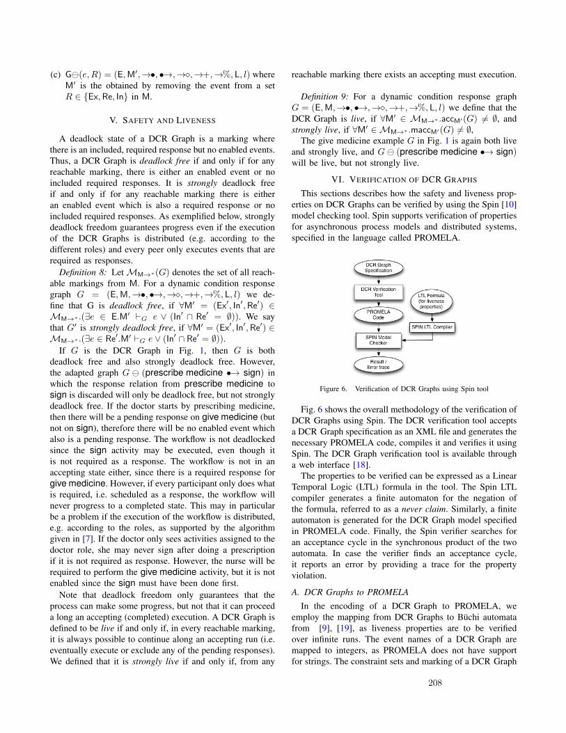
(c) G(e,R) = (E,M′,→•, •→,→�,→+,→%, L, l) whereM′ is the obtained by removing the event from a setR ∈ {Ex,Re, In} in M.
V. SAFETY AND LIVENESS
A deadlock state of a DCR Graph is a marking wherethere is an included, required response but no enabled events.Thus, a DCR Graph is deadlock free if and only if for anyreachable marking, there is either an enabled event or noincluded required responses. It is strongly deadlock freeif and only if for any reachable marking there is eitheran enabled event which is also a required response or noincluded required responses. As exemplified below, stronglydeadlock freedom guarantees progress even if the executionof the DCR Graphs is distributed (e.g. according to thedifferent roles) and every peer only executes events that arerequired as responses.
Definition 8: LetMM→∗(G) denotes the set of all reach-able markings from M. For a dynamic condition responsegraph G = (E,M,→•, •→,→�,→+,→%, L, l) we de-fine that G is deadlock free, if ∀M′ = (Ex′, In′,Re′) ∈MM→∗ .(∃e ∈ E.M′ `G e ∨ (In′ ∩ Re′ = ∅)). We saythat G′ is strongly deadlock free, if ∀M′ = (Ex′, In′,Re′) ∈MM→∗ .(∃e ∈ Re′.M′ `G e ∨ (In′ ∩ Re′ = ∅)).
If G is the DCR Graph in Fig. 1, then G is bothdeadlock free and also strongly deadlock free. However,the adapted graph G (prescribe medicine •→ sign) inwhich the response relation from prescribe medicine tosign is discarded will only be deadlock free, but not stronglydeadlock free. If the doctor starts by prescribing medicine,then there will be a pending response on give medicine (butnot on sign), therefore there will be no enabled event whichalso is a pending response. The workflow is not deadlockedsince the sign activity may be executed, even though itis not required as a response. The workflow is not in anaccepting state either, since there is a required response forgive medicine. However, if every participant only does whatis required, i.e. scheduled as a response, the workflow willnever progress to a completed state. This may in particularbe a problem if the execution of the workflow is distributed,e.g. according to the roles, as supported by the algorithmgiven in [7]. If the doctor only sees activities assigned to thedoctor role, she may never sign after doing a prescriptionif it is not required as response. However, the nurse will berequired to perform the give medicine activity, but it is notenabled since the sign must have been done first.
Note that deadlock freedom only guarantees that theprocess can make some progress, but not that it can proceeda long an accepting (completed) execution. A DCR Graph isdefined to be live if and only if, in every reachable marking,it is always possible to continue along an accepting run (i.e.eventually execute or exclude any of the pending responses).We defined that it is strongly live if and only if, from any
reachable marking there exists an accepting must execution.
Definition 9: For a dynamic condition response graphG = (E,M,→•, •→,→�,→+,→%, L, l) we define that theDCR Graph is live, if ∀M′ ∈ MM→∗ .accM′(G) 6= ∅, andstrongly live, if ∀M′ ∈MM→∗ .maccM′(G) 6= ∅,
The give medicine example G in Fig. 1 is again both liveand strongly live, and G (prescribe medicine •→ sign)will be live, but not strongly live.
VI. VERIFICATION OF DCR GRAPHS
This sections describes how the safety and liveness prop-erties on DCR Graphs can be verified by using the Spin [10]model checking tool. Spin supports verification of propertiesfor asynchronous process models and distributed systems,specified in the language called PROMELA.
Figure 6. Verification of DCR Graphs using Spin tool
Fig. 6 shows the overall methodology of the verification ofDCR Graphs using Spin. The DCR verification tool acceptsa DCR Graph specification as an XML file and generates thenecessary PROMELA code, compiles it and verifies it usingSpin. The DCR Graph verification tool is available througha web interface [18].
The properties to be verified can be expressed as a LinearTemporal Logic (LTL) formula in the tool. The Spin LTLcompiler generates a finite automaton for the negation ofthe formula, referred to as a never claim. Similarly, a finiteautomaton is generated for the DCR Graph model specifiedin PROMELA code. Finally, the Spin verifier searches foran acceptance cycle in the synchronous product of the twoautomata. In case the verifier finds an acceptance cycle,it reports an error by providing a trace for the propertyviolation.
A. DCR Graphs to PROMELA
In the encoding of a DCR Graph to PROMELA, weemploy the mapping from DCR Graphs to Buchi automatafrom [9], [19], as liveness properties are to be verifiedover infinite runs. The event names of a DCR Graph aremapped to integers, as PROMELA does not have supportfor strings. The constraint sets and marking of a DCR Graph
208
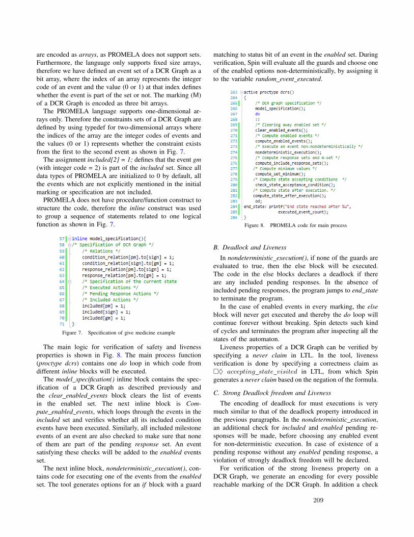
are encoded as arrays, as PROMELA does not support sets.Furthermore, the language only supports fixed size arrays,therefore we have defined an event set of a DCR Graph as abit array, where the index of an array represents the integercode of an event and the value (0 or 1) at that index defineswhether the event is part of the set or not. The marking (M)of a DCR Graph is encoded as three bit arrays.
The PROMELA language supports one-dimensional ar-rays only. Therefore the constraints sets of a DCR Graph aredefined by using typedef for two-dimensional arrays wherethe indices of the array are the integer codes of events andthe values (0 or 1) represents whether the constraint existsfrom the first to the second event as shown in Fig. 7.
The assignment included[2] = 1; defines that the event gm(with integer code = 2) is part of the included set. Since alldata types of PROMELA are initialized to 0 by default, allthe events which are not explicitly mentioned in the initialmarking or specification are not included.
PROMELA does not have procedure/function construct tostructure the code, therefore the inline construct was usedto group a sequence of statements related to one logicalfunction as shown in Fig. 7.
Figure 7. Specification of give medicine example
The main logic for verification of safety and livenessproperties is shown in Fig. 8. The main process function(proctype dcrs) contains one do loop in which code fromdifferent inline blocks will be executed.
The model specification() inline block contains the spec-ification of a DCR Graph as described previously andthe clear enabled events block clears the list of eventsin the enabled set. The next inline block is Com-pute enabled events, which loops through the events in theincluded set and verifies whether all its included conditionevents have been executed. Similarly, all included milestoneevents of an event are also checked to make sure that noneof them are part of the pending response set. An eventsatisfying these checks will be added to the enabled eventsset.
The next inline block, nondeterministic execution(), con-tains code for executing one of the events from the enabledset. The tool generates options for an if block with a guard
matching to status bit of an event in the enabled set. Duringverification, Spin will evaluate all the guards and choose oneof the enabled options non-deterministically, by assigning itto the variable random event executed.
Figure 8. PROMELA code for main process
B. Deadlock and Liveness
In nondeterministic execution(), if none of the guards areevaluated to true, then the else block will be executed.The code in the else blocks declares a deadlock if thereare any included pending responses. In the absence ofincluded pending responses, the program jumps to end stateto terminate the program.
In the case of enabled events in every marking, the elseblock will never get executed and thereby the do loop willcontinue forever without breaking. Spin detects such kindof cycles and terminates the program after inspecting all thestates of the automaton.
Liveness properties of a DCR Graph can be verified byspecifying a never claim in LTL. In the tool, livenessverification is done by specifying a correctness claim as�♦ accepting state visited in LTL, from which Spingenerates a never claim based on the negation of the formula.
C. Strong Deadlock freedom and Liveness
The encoding of deadlock for must executions is verymuch similar to that of the deadlock property introduced inthe previous paragraphs. In the nondeterministic execution,an additional check for included and enabled pending re-sponses will be made, before choosing any enabled eventfor non-deterministic execution. In case of existence of apending response without any enabled pending response, aviolation of strongly deadlock freedom will be declared.
For verification of the strong liveness property on aDCR Graph, we generate an encoding for every possiblereachable marking of the DCR Graph. In addition a check
209

will be made in the non-deterministic execution of events,to make sure that the enabled events are also pendingresponses.
D. Evaluation of Spin VerificationTable. I shows statistics for the Spin verification of the
healthcare workflow from the previous sections. The secondand third columns represent the number of events andconstraints in the DCR Graph. The number of reachablemarkings in the DCR Graph is shown in column 4. The lastthree columns display the statistics from Spin verification:the number of Spin program states, time taken in secondsand memory usage in megabytes respectively.
DCR Graph Spin statistics
Model E → states programstates
timesec.
memoryMB.
prescribemedicine 3 4 13 14,741 0.04 613.04
order tests 5 7 72 231,731 0.60 759.70prescribe+ order 6 11 116 602,289 1.67 775.20
adaptedprescribe+ order
7 11 460 3,267,596 9.37 880.70
createcase [5] 17 28 1386 15,614,513 63.1 1432.5
Table ISPIN VERIFICATION STATISTICS
Even though Spin verification on DCR Graphs is quiteuseful, we have noticed certain drawbacks. First of all, thenumber of Spin program states grows exponentially withthe number of events in a DCR Graph. For example, theadapted prescribe medicine example from Fig. 5 contains7 events and 11 constraints. But as shown in Table. I, theSpin program states are more than three million, even thoughthere are only 460 unique reachable markings in the buchiautomaton for the DCR Graph. The automata construction isinherently exponential, however, a further blow-up of Spinprogram states is caused by the lack of good data structuresin PROMELA for encoding sets and other complex types.This means that the event sets of a DCR Graphs have tobe encoded as fixed size arrays and these arrays have tobe iterated many times to calculate the updated markings.Moreover, every value change of a variable (e.g. loop index)is considered as unique program state in Spin. Additionally,the increase of Spin memory usage (last column) is also analarming issue, which could be problematic in verificationof larger models.
In addition to the above limitations, the output generatedby Spin is also not user friendly. Especially, it is difficult formodellers to figure out the counter example from the Spinerror trails. Therefore, we strongly believe that by perform-ing the verification directly on the reachable markings of aDCR Graph, it is possible to verify much larger models andprovide intuitive validation results.
VII. CONCLUSION
We have presented an approach to adaptive case manage-ment based on the recently introduced declarative processmodel Dynamic Condition Response (DCR) Graphs. Ourwork leverages three key features of DCR Graphs: 1) Itsdeclarative nature with implicit definition of states allow forsimple definitions of process composition and change, 2) itssimple operational semantics based on markings of the graphallowed us to extend the definitions of process compositionand change to running instances, and 3) the mapping ofDCR Graphs to the SPIN model checking tool allowed usto formally verify deadlock freedom and liveness for thedynamically changed adapted models.
The definition of deadlocks for DCR Graphs is new,and exploited that the markings of DCR Graphs allow todistinguish between which events may happen now (theenabled events), and which events must eventually happen(the required future responses). This allowed us to definea deadlock as a state where some event must eventuallyhappen, but no events may happen now. Moreover, we in-troduced a new notion of strongly deadlock freedom, whichintuitively means that even in a situation where every actoronly perform required actions there will be no deadlocks. Wealso introduced the notion of liveness and strong liveness forDCR Graphs
We found that the PROMELA language and its ability toverify both safety and liveness properties made SPIN easyto use as back-end verification tool for DCR Graphs andbenchmarked the verification on a small set of examples.However, the benchmarks also show that the resulting SPINmodels reach a quite large number of states for even smallDCR Graphs, which indicate that there may be an advantageto implement the verification algorithms directly for DCRGraphs. This could potentially explore the partial orderinformation of DCR Graphs and avoid constructing theinterleaved transition system model.
In future work we plan to investigate a native implemen-tation of model checking for DCR Graphs. We also plan toextend the approach to ACM presented in the present paperto DCR Graphs extended with data and nested sub graphsas defined in [17] and relate and compare our work to theGSM-approach [12].
REFERENCES
[1] Hanna Eberle, Tobias Unger, and Frank Leymann. Processfragments. In OTM ’09, pages 398–405. Springer-Verlag,2009. 3
[2] Clarence Ellis, Karim Keddara, and Grzegorz Rozenberg.Dynamic change within workflow systems. In Proceedingsof conference on Organizational computing systems, COCS’95, pages 10–21, New York, NY, USA, 1995. ACM. 1, 3, 4
[3] Wei-Dong Zhu et. al. Advanced Case Management with IBMCase Manager. IBM Redbooks, 2013. http://www.redbooks.ibm.com/redbooks/pdfs/sg247929.pdf. 4
210

[4] Thomas Hildebrandt and Raghava Rao Mukkamala. Declar-ative event-based workflow as distributed dynamic conditionresponse graphs. In PLACES, volume 69 of EPTCS, pages59–73, 2011. 1, 4
[5] Thomas Hildebrandt, Raghava Rao Mukkamala, and TijsSlaats. Designing a cross-organizational case managementsystem using dynamic condition response graphs. In Pro-ceedings of IEEE International EDOC Conference, 2011. 9
[6] Thomas Hildebrandt, Raghava Rao Mukkamala, and TijsSlaats. Nested dynamic condition response graphs. In Pro-ceedings of Fundamentals of Software Engineering (FSEN),April 2011. 1
[7] Thomas Hildebrandt, Raghava Rao Mukkamala, and TijsSlaats. Safe distribution of declarative processes. In 9th In-ternational Conference on Software Engineering and FormalMethods (SEFM) 2011, 2011. 1, 3, 7
[8] Thomas Hildebrandt, Raghava Rao Mukkamala, Tijs Slaats,and Francesco Zanitti. Modular context-sensitive and aspect-oriented processes with dynamic condition response graphs.In Foundations of Aspect-Oriented Languages 2013, 2013. 1,4
[9] Thomas T. Hildebrandt and Raghava Rao Mukkamala.Declarative event-based workflow as distributed dynamic con-dition response graphs. In PLACES, pages 59–73, 2010. 7
[10] Gerard J. Holzmann. The model checker spin. IEEE Trans.Softw. Eng., 23:279–295, May 1997. 2, 7
[11] Gerard J. Holzmann. SPIN Model Checker, The: Primer andReference Manual. Addison-Wesley Professional, 2004. 2
[12] Richard Hull. Formal study of business entities with life-cycles: Use cases, abstract models, and results. In TevfikBravetti, Mario; Bultan, editor, 7th International Workshop onWeb Services and Formal Methods, volume 6551 of LectureNotes in Computer Science, 2010. 1, 4, 9
[13] Wil Janssen, Radu Mateescu, Sjouke Mauw, and Jan Spring-intveld. Verifying business processes using spin. In Proceed-ings of the 4th International SPIN Workshop, pages 21–36,1998. 4
[14] Jana Koehler, Joerg Hofstetter, and Roland Woodtly. Capabil-ities and levels of maturity in it-based case management. InBusiness Process Mangement (BPM), LNCS. Springer Verlag,2012. 1
[15] Karen Marie Lyng, Thomas Hildebrandt, and Raghava RaoMukkamala. From paper based clinical practice guidelinesto declarative workflow management. In Process-orientedinformation systems in healthcare (ProHealth 08), pages 36–43. BPM 2008 Workshops, 2008. 1
[16] K.M. Lyng. Clinical guidelines in everyday praxis, implica-tions for computerization. Journal of Systems and InformationTechnology, 2009. 1
[17] Raghava Rao Mukkamala. A Formal Model For DeclarativeWorkflows: Dynamic Condition Response Graphs. PhD thesis,IT University of Copenhagen, June 2012. http://www.itu.dk/people/rao/phd-thesis/DCRGraphs-rao-PhD-thesis.pdf. 1, 2,5, 9
[18] Raghava Rao Mukkamala. Formal verification of dcr graphsusing spin. http://trustcare.itu.dk/dcrgraphs-verification/verificationWebUI.aspx, 2012. 2, 7
[19] Raghava Rao Mukkamala and Thomas Hildebrandt. Fromdynamic condition response structures to buchi automata.In Proceedings of 4th IEEE International Symposium onTheoretical Aspects of Software Engineering (TASE 2010),August 2010. 1, 2, 3, 4, 7
[20] Nicolas Mundbrod, Jens Kolb, and Manfred Reichert. To-wards a system support of collaborative knowledge work. In1st Int’l Workshop on Adaptive Case Management (ACM’12),BPM’12 Workshops, LNBIP. Springer, September 2012. 2
[21] Object Management Group (OMG). Case management modeland notation (cmmn). http://www.omg.org/spec/CMMN/,January 2013. 4
[22] Manfred Reichert and Peter Dadam. A framework fordynamic changes in workflow management systems. InConference on Database and Expert Systems Applications,1997. 3, 4
[23] I. Rychkova and S. Nurcan. Towards adaptability and con-trol for knowledge-intensive business processes: Declarativeconfigurable process specifications. In Hawaii InternationalConference on System Sciences, 2011. 1, 4
[24] Irina Rychkova. Towards automated support for case manage-ment processes with declarative configurable specifications.In BPM Workshops. Springer Berlin Heidelberg, 2013. 1, 4
[25] Tijs Slaats. Dcr graphs editor. http://www.itu.dk/research/models/wiki/index.php/DCR Graphs Editor, February 2013.1
[26] Tijs Slaats, Raghava Rao Mukkamala, Thomas Hildebrandt,and Morten Marquard. Exformatics declarative case manage-ment workflows as dcr graphs. In International Conferenceon Business Process Management (BPM2013), 2013. 1
[27] Keith D. Swenson. Mastering the Unpredictable: HowAdaptive Case Management Will Revolutionize the Way ThatKnowledge Workers Get Things Done. Meghan-Kiffer Press,2010. 1, 2
[28] KeithD. Swenson. Position: Bpmn is incompatible with acm.In Marcello Rosa and Pnina Soffer, editors, BPM Workshops,volume 132 of Lecture Notes in Business Information Pro-cessing, pages 55–58. Springer Berlin Heidelberg, 2013. 4
[29] W. M. P. Van Der Aalst. Exterminating the dynamic changebug: A concrete approach to support workflow change. In-formation Systems Frontiers, 3(3):297–317, September 2001.1, 3, 4
[30] Wil M. P. van der Aalst, Maja Pesic, and Helen Schonenberg.Declarative workflows: Balancing between flexibility andsupport. Computer Science - R&D, 23(2):99–113, 2009. 4
[31] Wil M.P van der Aalst and Maja Pesic. A declarativeapproach for flexible business processes management. InProceedings DPM 2006, LNCS. Springer Verlag, 2006. 1,4
211

Modular Context-Sensitive and Aspect-Oriented Processeswith Dynamic Condition Response Graphs
Thomas Hildebrandt1 Raghava Rao Mukkamala1 Tijs Slaats1,2 Francesco Zanitti11 IT University of Copenhagen, Rued Langgaardsvej 7, 2300 Copenhagen, Denmark
2 Exformatics A/S, Lautrupsgade 13, 2100 Copenhagen, Denmark{rao, hilde, tslaats, zanitti}@itu.dk
AbstractWe propose the recently introduced declarative and event-basedDynamic Condition Response (DCR) Graphs process model as aformal basis for modular implementation of context-sensitive andaspect-oriented processes. The proposal is supported by a new joinoperator allowing modular composition and refinement of DCRGraphs. We give small illustrative examples of DCR Graphs defin-ing context-sensitive processes where context-events dynamicallyenable and disable the need for authentication and the join opera-tor is used to add authentication to a process. Finally, we discussthe use of formal verification to ensure that processes satisfy safetyand liveness properties, and define two liveness properties (dead-lock freedom and liveness) that can be verified directly on the stategraph for DCR Graphs.
Categories and Subject Descriptors D.3.1 [Programming Lan-guages]: Formal Definitions and Theory - Semantics, Syntax
General Terms Design, Languages, Reliability, Verification
1. IntroductionThe terms context-sensitivity, context-awareness and context-dependencyare generally used to describe systems that adapt their behavior ac-cording to changes in their context. Changes in the context are nat-urally described as events, either provided by sensors, user inputsor messages from other programs. This suggests the application ofevent-driven programming to implement context-aware systems.Event-driven systems are normally based on the publish-subscribepattern. That is, at any time the system subscribes to specific (pat-terns of) events. Whenever a pattern has been detected, the systemreacts by performing a block of code, possibly publishing newevents.
In the present paper we propose to use the recently introducedevent-based declarative process model, Dynamic Condition Re-sponse Graphs (DCR Graphs) [3, 6, 7, 13], as a formal basis formodular and aspect-oriented construction of context-sensitive sys-tems. The modular and aspect-oriented construction is facilitatedby a new, general join operator. We give small examples that il-lustrate how the join operator can be used to merge processes, and
Permission to make digital or hard copies of all or part of this work for personal orclassroom use is granted without fee provided that copies are not made or distributedfor profit or commercial advantage and that copies bear this notice and the full citationon the first page. To copy otherwise, to republish, to post on servers or to redistributeto lists, requires prior specific permission and/or a fee.FOAL’13, March 26, 2013, Fukuoka, Japan.Copyright c© 2013 ACM 978-1-4503-1865-5/13/03. . . $15.00
discuss how merging is similar to adding advices and weaving ofaspects in AOP. The examples also show how the join operator canbe used to refine and more generally adapt behavior of a process,i.e. by replacing an event or a complete sub process with a newprocess.
It should be stressed that the proposal in the present paper isvery initial work. The DCR Graph model was developed with an-other application area in mind as a foundation for flexible work-flow languages as part of the second author’s PhD project [12].It has then subsequently been continued in the (ongoing) PhDprojects of the third and fourth authors focussing on respectivelydeveloping a formal foundation for the implementation of flexi-ble, cross-organizational workflow systems [5] and developing aprocess-oriented event-based programming language (PEPL) [4]for context-sensitive services based on DCR Graphs.
In Fig. 1 below we give a concrete example of a context-sensitive authorization process that we will use as running example.The example is inspired by a concrete case study of an oncologyworkflow process at a danish hospital [11].
The graph consists of five events (shown as boxes). Each eventcorresponds to the (possibly repeated) execution of an activity,which is indicated by a label assigned to the event and shown insidethe box. The activities in the example are thus action, authorize,reauthorize, normal and emergency.
Figure 1. Context-sensitive authorization process as DCR Graph.
One way to think of a DCR Graph is as an event-driven reactiveprogram, where the code-blocks usually executed when an eventpattern is detected have been replaced by specifications of responseevents, specifying activities that must eventually be executed (bythe process or the environment) whenever possible. That is, theoccurrence of an event schedules other events that must be executedin the future in order for the process to progress. The responseevents are specified in the graph by the response relation, indicated
212

graphically by the arrow with a bullet at the source and colouredblue to make it more easily visible. In the example we thus have aresponse relation from the reauthorize to the authorize event.
Moreover, every event can have a list of condition events andmilestone events. In order for an event to be enabled, i.e. its activityto be executable, its condition events must have been executed atleast once in the past and its milestone events must not currently bescheduled for execution. In the example, the authorize event is acondition for the reauthorize event and a milestone for the actionevent. The condition relation means in this example that reautho-rize can not be executed if authorize has not been executed at leastonce in the past. The milestone relation means that the action eventis blocked if an authorize event is scheduled for execution.
Finally, in addition to the specification of response, conditionand milestone events, a novel idea of DCR Graphs is the specifica-tion of events that are excluded and included when an event hap-pen. Exclusion and inclusion of events have a cross-cutting effecton the system similar to turning aspects on and off in aspect ori-ented programming: An excluded event is ignored as condition andmilestone of events and even if it is currently scheduled it will notbe required to be executed unless it is included again.
In the example, the event emergency excludes the authorizeand reauthorize events and the event normal includes the twoevents. Note we use the nested DCR Graphs notation introducedin [6], a relation to a box around events is simply a short hand forhaving the relation to all the sub events. Now, if an emergencyevent happens (e.g. representing that the condition of the patientbecomes critical), then the events authorize and reauthorize areexcluded. This means that even if authorize is scheduled for exe-cution and a milestone for action, then it is not disabling the actionevent. However, if the normal event happens, then authorize andreauthorize are again included.
The five relations (condition, response, milestone, include andexclude) completely describe the dynamic behavior of the process.Moreover, the state of a running process can be described by a tripleof finite sets of events, (Ex,Re, In) similar to markings of PetriNets [15, 16]. The set Ex records the previously executed events,the set Re describes the events scheduled for execution, and the setIn denotes the currently included events. The set Re thus containsevents schedules as responses to events that have been executed,but we also allow to define that some events are scheduled in theinitial marking of the graph.
We graphically visualize a marking (Ex,Re, In) by adding a(green) checkmark to every box for events in the Ex set, a (red)exclamation mark to every box for events in the Re set, and makingthe border dashed of boxes for events which are not in the In set.A run of a DCR Graph is then a (possibly infinite) sequence ofmarkings, where the (n + 1)th marking is obtained by executingone of the enabled events in the nth marking (adding it to the setEx) and updating the Re and In sets according to the relations.
An example run of the process in Fig. 1 is shown in Fig. 2. In theinitial marking (at the top), nothing has been executed, the eventsaction and authorize are scheduled, and every event is included.This state is described by the marking (∅, {action, authorize},E),where E is the set of all five events. In this state, only the eventsauthorize, normal and emergency are enabled. The event actionis blocked because it has authorize as milestone and authorizeis scheduled for execution. The event reauthorize is blocked be-cause it has authorize as condition, and this event has never beenexecuted.
Now, if the emergency event is executed then the state changesto the marking ({emergency}, {action, authorize},E\{authorize,reauthorize}), shown at the graph in the middle of Fig. 2. That is,emergency is recorded as executed, whereas action and autho-rize are still scheduled, but authorize and reauthorize are ex-
cluded. This implies that authorize is not longer considered asmilestone for action, which therefore is enabled. The markingshown at the bottom of Fig. 2 shows the state if the event actionis executed.
Figure 2. An example run of the authorization process.
Note that action can be executed several times. However, ifnormal is now executed, i.e. if the patient condition is no longercritical, then system moves to the marking shown in Fig. 3, whereauthorize and reauthorize are included again.
Figure 3. If the normal event is executed, then authorize is againrequired before action can be executed.
Since authorize is still scheduled in the marking in Fig. 3,the event action is not enabled and can not be executed unless
213

authorize is executed or excluded because the event emergencyis executed again.
Runs may be finite or infinite. We say that a run is acceptingif whenever an event is scheduled, it eventually gets excluded orexecuted. As shown in [12, 13], DCR Graphs can be mapped tothe standard Buchi-automata model, characterizing all runs as wellas fair runs as the accepting runs, and subsequently verified forsafety and liveness properties using the SPIN model checker [9].However, it can also be represented directly (and more compactly)as a so-called transition system with responses [2], which is simplya labelled transition system where each state is annotated by a setof labels, referred to as the response actions. The accepting runsof a transition system with responses is then the finite or infiniteruns where whenever a label is included in the response set of anintermediate state in the run, it will be excluded from the responseset in a subsequent state or executed.
It is worth stressing that there is no explicit sequencing of com-mands in the DCR Graphs process model. This makes it possible toweave, refine and adapt processes by the general join operator in-troduced in Sec. 3. If a new event is joined as a milestone for someexisting events in a process, and such that this new event is sched-uled whenever the existing events are scheduled as responses, thenthe new event must be executed before the existing events becomeenabled. Thus, the new event is similar to an advice in AOP, thatmust be executed before the targetted set of existing events whichcorrespond to join points.
After briefly recalling the formal definition of DCR Graphsin Sec. 2, we exemplify this aspect-oriented modularity in Sec. 3where the DCR Graph shown in Fig. 1 is joined with a anotherprocess describing a context-sensitive request/reply process shownin Fig. 4
We end by briefly summarizing the techniques for formal ver-ification and distribution of DCR Graphs developed so-far in theabove mentioned research projects and briefly touch on relatedwork.
2. DCR GraphsIn this section we give the formal definitions of DCR Graphs. Weemploy the following notation.Notation: For a setE we writeP(E) for the power set ofE (i.e. setof all subsets of E). For a binary relation→⊆ E ×E and a subsetξ ⊆ E we write → ξ and ξ→ for the set {e ∈ E | (∃e′ ∈ ξ |e → e′)} and the set {e ∈ E | (∃e′ ∈ ξ | e′ → e)} respectively,and abuse notation writing → e and e→ for → {e} and {e} →respectively when e ∈ E.
Formally, a DCR Graph is defined as follows.
DEFINITION 1. A Dynamic Condition Response Graph (DCR Graph)G is a tuple (E,M,→•, •→,→�,→+,→%, L, l), where
(i) E is a set of events,(ii) M ∈ isthemarking,P(E)× P(E)× P(E),
(iii) →•, •→,→�,→+,→%⊆ E × E is the condition, response,milestone, include and exclude relation respectively.
(iv) L is the set of labels and l : E → P(L) is a labeling functionmapping events to labels.
As explained in the introduction, the marking (ii) represents thestate of the DCR Graph and the five binary relations over the events(iii) define the constraints on the events and dynamic inclusion andexclusion. Finally, each event is mapped to a set of labels (iv).
In Def. 2 we formally define that an event e of a DCR Graphwith marking M = (Ex,Re, In) is enabled, written G ` e, when eis included in the current marking, i.e. e ∈ In, and all the includedevents that are conditions for it are in the set of executed events,i.e. (In∩ →• e) ⊆ Ex, and none of the included events that are
milestones for it are in the set of scheduled response events, i.e.(In∩ →�e) ⊆ E\Re. We then further define the change of themarking when an enabled event e is executed: Firstly, the evente is added to the set of executed events (Ex ∪ {e}). Secondly,the event is removed from the set of scheduled responses and allevents that are a response to the event e are added to the set ofscheduled responses ((Re \ {e}) ∪ e •→). Note that if an event isa response to itself, it will remain in the set of scheduled responsesafter its execution. Finally, the included events set is updated to theset (In\e→%)∪e→+, i.e. all the events that are excluded by e areremoved, and then all the events that are included by e are added.
DEFINITION 2. For a Dynamic Condition Response Graph G =(E,M,→•, •→,→�,→+,→%, L, l), and M = (Ex,Re, In) wedefine that an event e ∈ E is enabled, written G ` e, if e ∈In ∧ (In∩ →•e) ⊆ Ex and (In∩ →�e) ⊆ E\Re. We furtherdefine the result of executing the event e as (Ex,Re, In)⊕G e =def(Ex ∪ {e}, (Re \ {e}) ∪ e•→, (In \ e→%) ∪ e→+
).
Having defined when events are enabled for execution and theeffect of executing an event we define in Def. 3 the notion of finiteand infinite executions and when they are accepting. Intuitively, anexecution is accepting if any event which is scheduled and includedin any intermediate marking, is eventually executed or excluded.
DEFINITION 3. For a Dynamic Condition Response Graph G =(E,M,→•, •→,→�,→+,→%, L, l) we define an execution of Gto be a (finite or infinite) sequence of tuples {(Mi, ei, ai,M
′i)}i∈[k]
each consisting of a marking, an event, a label and another marking(the result of executing the event) such that M = M0 and ∀i ∈[k].ai ∈ l(ei)∧Gi ` ei∧M′i = Mi⊕G ei and ∀i ∈ [k−1].M′i =Mi+1, where Gi = (E,Mi,→•, •→,→�,→+,→%, L, l). We saythe execution is accepting if ∀i ∈ [k].
(∀e ∈ Ini ∩ Rei.∃j ≥
i.ej = e ∨ e 6∈ In′j)), where Mi = (Exi, Ini,Rei) and M′j =
(Ex′j , In′j ,Re
′j). Let exeM(G) and accM(G) denote respectively the
set of all executions and all accepting executions of G starting inmarking M. Finally we say that a marking M′ is reachable in G(from the marking M) if there exists a finite execution ending in M′
and letMM→∗(G) denote the set of all reachable markings fromM.
A marking in a DCR Graph is accepting, if there are no includedscheduled events that required as responses. Thus, a deadlock statecan be defined as a state where there is an included scheduledevent, but without any enabled events. We say that a DCR Graphis deadlock free if and only if there is no reachable deadlock state.
DEFINITION 4. For a dynamic condition response graph G =(E,M,→•, •→,→�,→+,→%, L, l) we define that G is deadlockfree, if ∀M′ = (Ex′, In′,Re′) ∈ MM→∗ .(∃e ∈ E.G′ ` e ∨ (In′ ∩Re′ = ∅)), for G′ = (E,M′,→•, •→,→�,→+,→%, L, l).
A DCR Graph is defined to be live if and only if, in every reach-able marking, it is always possible to continue along an acceptingrun.
DEFINITION 5. For a dynamic condition response graph G =(E,M,→•, •→,→�,→+,→%, L, l) we define that the DCR Graphis live, if ∀M′ ∈MM→∗ .accM′(G) 6= ∅.
3. Process CompositionIn this section we define a new general join operation on DCRGraphs which supports modular, aspect-oriented composition andrefinement of DCR Graphs. The join operation is defined relativeto two join relations C and B, which specify which events in theleft (right) graph are replaced by events in the right (left) graph.
214

In particular the join operation allows in special cases for basicunion of graphs and refinement of events, that is, substituting anevent by an entire new sub graph.
Before giving the formal definition, we will give an example ofhow to join a process graph with another, where one event in theformer graph is refined by two events in the latter process.
The DCR Graph Grr in Fig. 4 below shows a process for acontext-sensitive request/reply pattern.
Figure 4. A context-sensitive request/reply process
If a request event happens, the reply is scheduled as response.The reply event is excluded if it is executed, or a cancel event sub-sequently happens. However, it will be included (and scheduled)again if a new request event happens. As for the example given inthe introduction, the cancel event may be triggered by some changeof conditions in the context of the process.
We can now use the join operation to define a context-sensitiverequest/reply process where the reply needs (context-sensitive) au-thorization as defined in the DCR Graph Gauth given in Fig. 1 inthe introduction.
The intention is to merge the two process graphs, but suchthat the reply event in Grr is replaced by the authorizeand action events in Gauth. The result is the graph shown inFig. 5 and formally defined as Grrauth = Grr CB Gauth forC= {(reply, {authorize, action})} and B= ∅.
Figure 5. Joining context-sensitive request/reply and authorizationprocesses
Informally, the two event sets have been joined, replacing thereply event in the graph Grr with the two events authorizeand action in the Gauth graph, while inheriting all relationsbetween the replaced event and other events in Grr . Recall, thatrelations to the box around authorize and action is merely
a convinient way to represent relations to both authorize andaction.
To ease readability we may adopt a programming languagenotation for the join operation, writing the above join as follows.
Listing 1. Using Join to Authorize a ReplyCSRequestReplyAuth =j o i n CSRequestReply and C S A u t h o r i z a t i o nwhere r e p l y < { a u t h o r i z e , a c t i o n }
Below we give the formal definition of the join operator.
DEFINITION 6. Assume DCR Graphs Gi = (Ei,Mi,→•i, •→i
,→�i,→+i,→%i, Li, li) where Mi = (Exi,Rei, Ini) for i ∈{1, 2} and join relations C: E1 ⇀ P(E2) and B: E2 ⇀ P(E1).The join of G1 and G2 relative to C and B is defined as G1 CBG2 = (E,M,→•, •→,→�,→+,→%, L, l), where
(i) ∀e ∈ dom(C). C (e) ∩ dom(B) = ∅ and ∀e ∈ dom(B). B(e) ∩ dom(C) = ∅
(ii) E = E′1 ∪ E′2 for E′1 = E1\dom(C) and E′2 = E2\dom(B)(iii) M = (Ex,Re, In), where: Ex = Ex1 ∩ E′1 ∪ Ex2 ∩ E′2,
In = In1 ∩ E′1 ∪ In2 ∩ E′2 and Re = Re1 ∩ E′1 ∪ Re2 ∩ E′2,(iv) →=E−1→1 ∪ →1E ∪ D−1→2 ∪ →2D for each→∈ {→•
, •→,→�,→+,→%} and E= {(e, e′) | e ∈ E1 ∧ e′ ∈C(e) ∪ {e}} and D= {(e, e′) | e ∈ E2 ∧ e′ ∈B(e) ∪ {e}}
(v) L = L1 ∪ L2
(vi) l(e) =
l1(e) ∪ l2(e) if e ∈ E′1 ∩ E′2l1(e) if e ∈ E′1\E′2l2(e) if e ∈ E′2\E′1
The first condition, (i), guarantees that there are no circular refine-ments. That is, an event in G1 can not be refined by an event in G2
which is also refined by an event in G1 and vice versa. The sec-ond condition, (ii), states that the set of events in the joined graphconsists of all the events of the two graphs, that have not been re-fined by events in the other graph. The third condition, (iii), definesthe join of the markings of the graphs. It simply inherits the mark-ings from the two graphs. Note that the fact that markings are alsojoined means that we can also apply the join operator on computingprocesses. Condition (iv) defines the extension of the relations tothe refining events. The relationE is the reflexive closure of the leftjoinC relation, i.e. e E e′ if and only if e C e′ or e = e′. Similarly,D is the reflexive closure of B. The relation E−1→1 is then the re-lational composition ofE−1 (the inverse ofE) and the relation→1,and similarly the relation→1E is the relational composition of→1
and E. That is, e(E−1→1 ∪ →1E)e′ if
• e→1 e′, or
• e→1 e′′′ and e′′′ C e′, or
• e′′ C e and e′′ →1 e′.
Considering our example in Fig. 5, this definition implies that e.g.cancel will exclude both action and authorize. But notethat the self-exclude relation on reply, enforcing the ”linearity”constraint that only one reply can only be carried out for eachrequest, is not kept. This is because relations between events thatare replaced, and thus in particular self-relations are not kept. Therationale for not keeping these relations are that a join shouldallow for removing constraints on the refined events. To keep theproperty that the action can only be carried out once for eachrequest, the refining graph Gauth should have an exclude relationfrom action to itself.
Finally, conditions (v) and (vi) define the label set as the unionof the two label sets, and the labeling of events by the original la-bel for events that are not shared and the union of the label set
215

for shared events. Since we have not used the label function in thepresent paper it can safely be ignored. For the curious reader, the la-beling function allows to have distinct events with the same ”exter-nal” label, which is useful for some practical applications, as wellas for proving that every Buchi-automaton can be represented by aDCR Graph. This means in particular that the DCR Graphsmodelis more expressive that LTL.
As indicated in the beginning of the section, we may deriveoperations G\e, G[e C G′] and G∪G′ for respectively discardingan event e, refining an event e by G′ and taking the union of twographs G and G′ as special cases of the join operator.
DEFINITION 7. For a DCR Graph G = (E1,Mi,→•i, •→i,→�i,→+i,→%i, Li, li) for i ∈ {1, 2} and e ∈ E1 define
• (Discard) G1\e = G1 CB G∅ where C= (e, ∅) and G∅ is theempty DCR Graph, i.e. the DCR Graph with no events,• (Refine) G1[e C G2] = G1 CB G2 where C= (e, E2) andB= ∅,• (Union) G1 ∪G2 = G1 CB G2 where C= ∅ and B= ∅.
As an example of the discard operation, we may remove theability to cancel requests in the graphGrrauth in Fig. 5 by discard-ing the cancel event, taking the graph Grrauth\cancel.
As an example of the refine operation, we may add the ”linear-ity” constraint to action in Grrauth, i.e. that it can be executedat most once for every request. This is done with a refine operationGrrauth[action C Glinact], where Glinact is the DCR Graph({action}, (∅, ∅, ∅), ∅, ∅, ∅, ∅, (action, action), ∅, ∅), i.e. thegraph with an empty marking and a single event action relatedto itself by the exclude relation, and no other relations.
3.1 Aspect Oriented and Modular DCR GraphsIn an aspect oriented language based on DCR Graphs, we proposeusing the join operator to define an operator for adding ”before”advices for a subset of events (the joincut). This could for instancebe done by refining every event e in the joincut by a DCR Graphthat adds an advice sub process as a milestone before the evente, ad e.g. the authorize event before the action event inFig. 1. Then, every time an event e in the join cut is scheduledfor execution, every event in the advice sub process will also bescheduled for execution, and must be executed before executing edue to the milestone relation.
Dually, an ”after” advice may be added to an event e by joininga graph that has a response, condition and include relation from e tothe advice sub process, like for the request and reply eventsin the Grr graph in Fig. 4. This ensures that the advice must becarried out once after the event e. These two operations can then becombined to have both ”before” and ”after” advices.
Toggling of advices, e.g. as a result of context-events, can beachieved by joining in events that include and exclude the advicesub processes, e.g. like the normal and emergency events inFig. 1. One can further constrain when an advice can be toggled asin Fig. 4, where the reply action can be cancelled, but only after therequest has happened.
Finally, the join operator can also be considered as a generalway of allowing modular definition of DCR Graphs. However, itshould be stressed, that the join operator provide no guarantees forpreserving safety and liveness properties. Indeed, it is easy to joingraphs and achieve a circular condition dependency between eventsthat may lead to a deadlock state if one of the events are requiredas response (and can not be excluded). Similarly, the join operatormay introduce the possibility of a life lock, i.e. a DCR Graph withan infinite run that is not accepting and has no way of breaking outof the loop.
It is possible to verify safety and liveness properties of the com-posed DCR Graphs, e.g. by mapping the DCR Graph to a Buchi-automaton and verify the properties using the SPIN model checkeras shown in [12]. This is however time consuming when the size ofthe processes grow. A more efficient verification currently exploredis to carry out the verification on the corresponding transition sys-tems with responses. Finally, an even more efficient guarantee ofwell-behaved modular composition, which we are currently inves-tigating, is to define a notion of behavioral type for DCR Graphsbased on the work on session types, which then guarantee that 1)well-typed graphs are safe and live, and 2) if compatible, well-typed DCR Graphs are joined, then the resulting graph is againwell-typed.
4. ConclusionWe have proposed the declarative, event-based DCR Graphs modelas a foundation for modular construction of context-sensitive,aspect-oriented processes. Concretely, we showed how the dynamicexclusion and inclusion primitives of DCR Graphs allow to turn therelevance of events as conditions/milestones and responses for anyother event in the model on and off. It was exemplified by a simpleauthorization process fragment, where the need for authorizationcan be toggled by events signaling wether the context situation isan emergency or normal. Another example was a request/reply pro-cess fragment, where the reply can be cancelled by a cancel event inthe context. Moreover, we presented a new join operator for DCRGraphs, allowing both modular composition and refinement, exem-plified by joining the request/reply process and the authorizationprocess, by which the reply was refined into two events, an actionevent (i.e. representing the reply) and an authorization event, andthe remaining events and relations for authorization were inherited.
A key point is that aspects are not turned on and off whenprocesses are initiated, but asynchronously at any point duringthe execution of the process. Another key point is that the formalsemantics allows us to verify if the defined process, e.g. obtainedby joining processes, have safety or liveness problems. As shownin [12, 13], DCR Graphs can be mapped to Buchi-automata. In [12]an implementation of this mapping and its application to verifysafety and liveness properties of DCR Graphs using the SPINmodel-checker are described. Recently we have developed a modelchecker that allows to verify properties directly on DCR Graphs. Itavoids the translation to Buchi-automata and seems more efficient,however this is still work in progress. In [7] we have developed atechnique for distributing DCR Graphs, which is somehow reverseto the composition operator. It allows to divide a DCR Graph in acollection of (not necessarily disjoint) sub graphs, which can thenbe executed at different locations. Finally, the fourth author hasdeveloped a prototype implemenation of PEPL [4] where eventsare extended with data, and the third author has implemented aworkflow engine at Exformatics A/S based on DCR Graphs withdata.
Related work: It goes beyond the scope of the present paper togive a comprehensive overview of related work. Context-orientedprogramming (e.g. [8, 18]) introduces the notion of layers in nor-mal object-oriented, block structured programming languages suchas Java, allowing features (aspects) to be activated or deactivateddepending on the current context. The selection of active layersare typically done using the with primitive when methods are in-voked. In [10], the event-driven and context-oriented approachesare combined, allowing events triggered in other threads to activateand de-activate layers somewhat similar to the include and excludeprimitives of DCR Graphs.
The use of declarative primitives for the description of pro-cesses, and workflow processes in particular, is also treated in thework on Declare [19, 20]. Declare is similar to DCR Graphs in
216

that processes are specified by temporal relations between events,indeed, the condition and responses relations are specified usingthe same graphical notation. Another related approac would beto specify processes using a temporal logic like LTL [14, 17]or CTL [1]. In [14] is shown that primitives similar to thoseused in DCR Graphs can indeed be represented in LTL. How-ever, neither Declare, LTL nor CTL have explicit operators forthe inclusion and exclusion of events as in DCR Graphs. Con-sequently, toggling of aspects can not simply be added by join-ing additional constraints. It is instead necessary to rewrite thelogical formula (or Declare process) in a non trivial way. As anexample, consider the request-reply-cancel pattern in Fig. 4. Therequest-reply pattern alone would typically be expressed in LTL bya formula like G(request =⇒ Freply) ∧ (Freply =⇒¬replyUrequest) ∧ G(reply =⇒ N(Freply =⇒¬replyUrequest)), where G reads Generally, F reads Future,U reads Until and N is the Next operator. That is, 1) it is gen-erally the case that if a request happens, then a reply happensin the future, 2) if a reply happens, then that reply can not hap-pen before at least one request has happened, and 3) if a replyhappens, then if another reply happens some time in the future,it will not happen before a new request has happened. Now, toadd the cancel option, it is ncecessary to rewrite the formula, it isnot possible simply to add new constraints e.g. as a conjunction.This is because 1) a reply is not required if a cancel event hap-pens, i.e. one must change the first conjunct to G(request =⇒F (reply ∨ cancel)), 2) after a cancel event, a reply shouldnot occur until we have seen a new request, i.e. the third con-junct becomes G(reply ∨ cancel =⇒ N(Freply =⇒¬replyUrequest)) and 3) a cancel event should not occur be-fore the first request has happened, i.e. we should add an additionalconjunct (Fcancel =⇒ ¬cancelUrequest). In general, ifthe LTL formula does not have this specific form as given by DCRGraphs, we claim that it would be non-trivial to define how for-mulas should be changed to toggle aspects on and off, and at leastnot as simple as the join operator of DCR Graphs proposed in thepresent paper.
AcknowledgmentsThis research is supported by IT University of Copenhagen, Ex-formatics A/S, an Industrial PhD grant and the Danish Council forStrategic Research through the Jingling Genies project, grant no.:2106-080046. We would like to thank the anonymous reviewers forcareful reviews and suggestions.
References[1] M. Ben-Ari, Z. Manna, and A. Pnueli. The temporal logic of branching
time. In J. White, R. J. Lipton, and P. C. Goldberg, editors, POPL,pages 164–176. ACM Press, 1981. ISBN 0-89791-029-X. 6
[2] M. Carbone, T. T. Hildebrandt, G. Perrone, and A. Wasowski. Refine-ment for transition systems with responses. In S. S. Bauer and J.-B.Raclet, editors, FIT, volume 87 of EPTCS, pages 48–55, 2012. 3
[3] T. Hildebrandt and R. R. Mukkamala. Declarative event-based workflow as distributed dynamic condition responsegraphs. In PLACES, volume 69 of EPTCS, pages 59–73, 2011.URL http://www.itu.dk/people/rao/rao_files/dcrsplacescamredver.pdf. 1
[4] T. Hildebrandt and F. Zanitti. A process-oriented event-based pro-gramming language. In F. Bry, A. Paschke, P. T. Eugster, C. Fetzer,and A. Behrend, editors, DEBS, pages 377–378. ACM, 2012. ISBN978-1-4503-1315-5. 1, 5
[5] T. Hildebrandt, R. R. Mukkamala, and T. Slaats. Designing a cross-organizational case management system using dynamic condition re-sponse graphs. In Proceedings of IEEE International EDOC Confer-
ence, 2011. URL http://www.itu.dk/people/rao/pubs_accepted/dcrscasestudy-edoc11.pdf. 1
[6] T. Hildebrandt, R. R. Mukkamala, and T. Slaats. Nested dynamic con-dition response graphs. In Proceedings of Fundamentals of SoftwareEngineering (FSEN), April 2011. URL http://www.itu.dk/people/rao/pubs_accepted/fsenpaper.pdf. 1, 2
[7] T. Hildebrandt, R. R. Mukkamala, and T. Slaats. Safe distribution ofdeclarative processes. In 9th International Conference on SoftwareEngineering and Formal Methods (SEFM) 2011, 2011. 1, 5
[8] R. Hirschfeld, P. Costanza, and O. Nierstrasz. Context-oriented pro-gramming. Journal of Object Technology, 7(3):125151, March Aprile2008. 5
[9] G. J. Holzmann. SPIN Model Checker, The: Primer and ReferenceManual. Addison-Wesley Professional, 2004. 3
[10] T. Kamina, T. Aotani, and H. Masuhara. Eventcj: a context-orientedprogramming language with declarative event-based context tran-sition. In Proceedings of the tenth international conference onAspect-oriented software development, AOSD ’11, pages 253–264,New York, NY, USA, 2011. ACM. ISBN 978-1-4503-0605-8. doi:10.1145/1960275.1960305. URL http://doi.acm.org/10.1145/1960275.1960305. 5
[11] K. M. Lyng, T. Hildebrandt, and R. R. Mukkamala. From paper basedclinical practice guidelines to declarative workflow management. InProcess-oriented information systems in healthcare (ProHealth 08),pages 36–43. BPM 2008 Workshops, 2008. URL http://www.itu.dk/people/hilde/Papers/ProHealth08.pdf. 1
[12] R. R. Mukkamala. A Formal Model For Declarative Workflows:Dynamic Condition Response Graphs. PhD thesis, IT University ofCopenhagen, June 2012. http://www.itu.dk/people/rao/phd-thesis/DCRGraphs-rao-PhD-thesis.pdf. 1, 3, 5
[13] R. R. Mukkamala and T. Hildebrandt. From dynamic con-dition response structures to buchi automata. In Proceed-ings of 4th IEEE International Symposium on TheoreticalAspects of Software Engineering (TASE 2010), August 2010.URL http://www.itu.dk/people/rao/rao_files/dcrsextendedabstractTase2010.pdf. 1, 3, 5
[14] R. R. Mukkamala, T. Hildebrandt, and J. B. Tøth. The resultmakeronline consultant: From declarative workflow management in practiceto LTL. In Proceeding of DDBP, 2008. 6
[15] J. L. Peterson. Petri Net Theory and the Modeling of Systems. PrenticeHall PTR, Upper Saddle River, NJ, USA, 1981. ISBN 0136619835. 2
[16] C. A. Petri. Kommunikation mit Automaten. PhD thesis, UniversitetHamburg, 1962. 2
[17] A. Pnueli. The temporal logic of programs. In FOCS, pages 46–57.IEEE Computer Society, 1977. 6
[18] G. Salvaneschi, C. Ghezzi, and M. Pradella. Context-oriented pro-gramming: A programming paradigm for autonomic systems. CoRR,abs/1105.0069, 2011. 5
[19] W. van der Aalst, M. Pesic, H. Schonenberg, M. Westergaard, andF. M. Maggi. Declare. Webpage, 2010. http://www.win.tue.nl/declare/. 5
[20] W. M. van der Aalst and M. Pesic. A declarative approach for flexiblebusiness processes management. In Proceedings DPM 2006, LNCS.Springer Verlag, 2006. ISBN 978-3-540-38444-1. 5
217
Towards a Foundation for Modular Run-timeAdaptable Process-Aware Information Systems?
Søren Debois1, Thomas Hildebrandt1, and Tijs Slaats1,2
1 IT University of Copenhagendebois,hilde,[email protected]
2 Exformatics A/[email protected]
Abstract. We present the DCR∗ process language as a first step towardsa foundation for modular process-aware information systems allowingdynamic creation of sub-processes with independent life-cycles and safe,run-time adaptation. The DCR∗ process language is a constraint-basedprocess language generalising event structures. As the first main technicalresult we formalise when an adaptation is conservative, i.e. preserves theconstraints of the adapted process and provide a decidable approxima-tion to conservative adaptation referred to as non-intrusive adaptations.Such approximation is crucial, since we as the second main technicalcontribution prove that the DCR∗ language is Turing complete. Thisis in contrast to the sub-language of DCR processes, without dynamicsub-processes. This language corresponds to the model of DCR graphsintroduced in previous work and known to charatise exactly languagesthat are the union of a regular and an ω-regular language. The devel-opments throughout the paper is exemplified with a running exampleinspired by a process-aware information system for handling grant ap-plications, for which our industrial partner has recently provided a DCRgraph based implementation. Also, an online prototype implementationof the DCR∗ language can be found at http://tiger.itu.dk:8018/.
1 Introduction
Software systems today control increasingly complex processes operating in un-predictable contexts. At the same time, it is becoming more and more criticalthat the software behaves correctly, e.g. that it is compliant with safety, securityand legal regulations. The combination of complexity, unpredictability and needfor compliancy has lead to a general understanding that a foundation for theimplementation of modular, run-time adaptable and formally verifiable softwaresystems is needed. This is not least the case in the fields of Process-Aware In-formation Systems (PAIS) [34] and Business Process Management (BPM) [3],which constitute the context of the present work. The fields deal with systemsdriven by explicit process designs for the enactment and management of busi-ness processes and human workflows, and the study of formalisms for describing
? supported by the Velux foundation (grant 33295) and Innovation Fund Denmark.
218
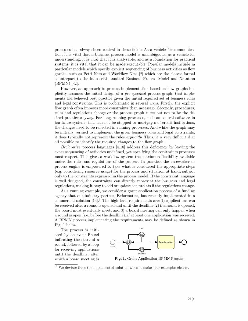
processes has always been central in these fields: As a vehicle for communica-tion, it is vital that a business process model is unambiguous; as a vehicle forunderstanding, it is vital that it is analysable; and as a foundation for practicalsystems, it is vital that it can be made executable. Popular models include inparticular models which specify explicit sequencing of business activities as flowgraphs, such as Petri Nets and Workflow Nets [2] which are the closest formalcounterpart to the industrial standard Business Process Model and Notation(BPMN) [32].
However, an approach to process implementation based on flow graphs im-plicitly assumes the initial design of a pre-specified process graph, that imple-ments the believed best practice given the initial required set of business rulesand legal constraints. This is problematic in several ways: Firstly, the explicitflow graph often imposes more constraints than necessary. Secondly, procedures,rules and regulations change or the process graph turns out not to be the de-sired practice anyway. For long running processes, such as control software inhardware systems that can not be stopped or mortgages of credit institutions,the changes need to be reflected in running processes. And while the graph maybe initially verified to implement the given business rules and legal constraints,it does typically not represent the rules explicitly. Thus, it is very difficult if atall possible to identify the required changes to the flow graph.
Declarative process languages [4,18] address this deficiency by leaving theexact sequencing of activities undefined, yet specifying the constraints processesmust respect. This gives a workflow system the maximum flexibility availableunder the rules and regulations of the process. In practice, the caseworker orprocess engine is empowered to take what is considered the appropriate steps(e.g. considering resource usage) for the process and situation at hand, subjectonly to the constraints expressed in the process model. If the constraint languageis well designed, the constraints can directly represent the business and legalregulations, making it easy to add or update constraints if the regulations change.
As a running example, we consider a grant application process of a fundingagency that our industry partner, Exformatics, has recently implemented in acommercial solution [14].3 The high-level requirements are: 1) applications canbe received after a round is opened and until the deadline, 2) if a round is opened,the board must eventually meet, and 3) a board meeting can only happen whena round is open (i.e. before the deadline), if at least one application was received.A BPMN process implementing the requirements may be defined as shown inFig. 1 below.
����������� ��
� ���
�������
����
� �����������
Fig. 1. Grant Application BPMN Process
The process is initi-ated by an event Roundindicating the start of around, followed by a loopfor receiving applicationsuntil the deadline, afterwhich a board meeting is
3 We deviate from the implemented solution when it makes our examples clearer.
219

held. However, the requirements are not explicitly represented in the processdiagram, and moreover, the process introduces unnecessary, or at least unspeci-fied constraints. For instance, no board meeting can be held before the deadline,even if applications are received, and it is not possible to reopen the round, e.g. ifinsufficiently many good applications were received. Of course, these possibilitiesmay be modelled, but with the cost of making the process graph more complex.
Our industry partner Exformatics employs a declarative, graphical processnotation, Dynamic Condition Response (DCR) Graphs, introduced in [18,30] anddeveloped further in [19,7,31,20,12]. As exemplified in Fig. 2 below (producedwith the tool at http://tiger.itu.dk:8018/), the DCR Graphs notation al-lows to specify the process by the four events (Receive, Deadline, Round, BoardMeeting) and four relations between the events.
Fig. 2. Grant ApplicationDCR Graph Process
The Receive event is dashed, representing thatit is initially excluded from the process. The linefrom Round to Receive with a + sign at the endis an include relation, meaning that Receive is dy-namically included if the event Round (the start ofa round) happens. Dually, the line from Deadline toReceive with a % sign is an exclude relation, mean-ing that Receive is dynamically excluded if the eventDeadline happens. Together, these two relations rep-resent the first requirement. The arrow from Roundto Board Meeting with a bullet at the start repre-sents that Board Meeting is a response to (i.e. musthappen eventually after) the Round event, as statedin the second requirement. Dually, the arrow fromReceive to Board Meeting with a bullet at the endrepresents that Receive is a condition for Board Meeting, meaning that if Receiveis included, i.e. a round is open, it must have happened before Board Meetingcan happen, as stated in the third requirement.
The operational semantics of a DCR Graph is defined in terms of a markingassigning a triple of booleans (h, i, r) to each event, indicating whether or notthe event previously (h)appened, is currently (i)ncluded, and/or is (r)estless.An event may be excluded in the initial marking and be dynamically includedand excluded if it is related to other events by include and exclude relations,as illustrated by the Receive event above. Similarly, an event may be restless inthe initial marking or become restless because it is a response to an event thathappened as for the Board Meeting event above. Finite or infinite executions arethen defined to be accepting only if every restless event is executed or excludedat a later point in the execution. As described in [18,30], (labelled) DCR Graphsis a conservative generalisation of (labelled) prime event structures, allowingfinite representations of infinite behaviour and to express liveness properties.The former is achieved by allowing an event to happen more than once andchange dynamically between being in conflict (excluded) and being consistent
220
(included) with the current state. The latter is achieved via the notion of restlessevents and the acceptance criteria described above.
Recently, an extension of DCR Graphs to so-called hierarchical DCR Graphs,supporting dynamic creation of sub-processes with (local) events and indepen-dent life cycles has been presented [12]. This extension was motivated in practiceby the funding agency process above, e.g. to allow each received application tohave its own approval events and decision life cycle, and thereby recording thedecision made for each application. However, although the graphical notationof DCR Graphs has been adopted by industry, it does not scale well to largerand more complex processes due to lack of compositionality. Also, the expressivepower of hierarchical DCR Graphs was left open by [12].
The central contribution of the present paper is to provide the DCR∗ processlanguage, a core constraint-based process language for modular process-awareinformation systems with dynamic creation of sub-processes with independentlife-cycles, based on the primitives introduced in (hierarchical) DCR Graphs,but equipped with a compositional operational semantics. The compositionalsemantics provides means for modular definition of and reasoning for DCR∗ pro-cesses. As an application, we show that the DCR∗ language supports run-timeadaptation by composition. We formalise when an adaptation is conservative,i.e. preserve requirements of the adapted process and provide as our first techni-cal contribution a syntactic, and thus decidable, approximation to conservativeadaptation referred to as non-intrusive adaptations. Such approximation is cru-cial, since we as a second technical contribution prove by an encoding of Minskymachines, that the DCR∗ language is in fact Turing complete. This is in con-trast to the sub-language of DCR processes corresponding to DCR Graphs, i.e.without dynamic sub-processes and local events, that can be shown to charatiseexactly languages that are the union of a regular and an ω-regular language(sketched in [30] and proven in the full version of the paper).
Overview of the paper: In Sec. 2 we provide the DCR process language andits compositional semantics. We then extend the language in Sec. 3 to DCR∗ sup-porting dynamic creation of interacting sub-processes with fresh (local) events.We address run-time adaptation by composition in Sec. 4, formalise when andadaptation is conservative and provide the syntactic, non-invasiveness approxi-mation to conservative adaptation. In Sec. 5 we prove that the DCR∗ language isTuring complete. Finally, we conclude and outline in Sec. 6 related, current andfuture directions of work exploiting the results in the present paper. An online, re-search prototype implementation of the process languages presented in the paper,with a mapping to DCR Graphs, can be found at http://tiger.itu.dk:8018/.
2 Dynamic Condition Response (DCR) Processes
Below we introduce the Dynamic Condition Response (DCR) process language.As already informally described in the introduction, it is based on the notionsof dynamic inclusion and exclusion of labelled events, related by conditions andresponse relations introduced in DCR Graphs [30,18].
221
We assume fixed universes of events E and labels L; each event e ∈ E has anassociated label `(e) ∈ L. A DCR process [M ] T comprises a marking M and aterm T . The syntax of both are given in Fig. 3 below.
T,U ::= f →• e condition
| f ←• e response
| f +← e inclusion
| f %← e exclusion
| T | U parallel
| 0 unit
φ ::= t | f boolean value
Φ ::= (φ, φ, φ) event state
M,N ::= M, e : Φ marking
P,Q ::= [M ] T process
Fig. 3. DCR Processes Syntax.
A term is a parallel composition of relations between events. We recall fromthe introduction how the relations regulate what behaviour the term may exhibit:
1. A condition f →• e imposes the constraint that for event e to happen, theevent f must either previously have happened or currently be excluded.
2. A response f ←• e imposes the effect that when e happens, f becomesrestless and must eventually happen or be excluded.
3. An exclusion f %← e imposes the effect that when e happens, it excludes f .An excluded event cannot happen; it is ignored as a condition; and it neednot happen if restless, unless it is re-included by the final relation:
4. An inclusion f +← e imposes the effect that when the event e happens, itre-includes the event f .
All four relations refer to a marking M , a finite map from events to triples ofbooleans (h, i, r), referred to as the event state and indicating whether or notthe event previously (h)appened, is currently (i)ncluded, and/or is (r)estless. Arestless event represents an unfulfilled obligation: once it happens, it ceases tobe restless. As commonly done for environments, we write markings as finitelists of pairs of events and event states, e.g. e1 : Φ1, . . . , ek : Φk but treat themas maps, writing dom(M) and M(e), and understand M, e : Φ to be undefinedwhen e ∈ dom(M). The free events fe(T ) of a term T is (for now) simply the setof events appearing in it. (This changes when we introduce local events in Sec. 3below.) We require of a process P = [M ] T that fe(T ) ⊆ dom(M), and so definefe(P ) = dom(M). The alphabet alph(P ) is the set of labels of its free events.
Example 1 (Grant process term). The example of fig. 2 can be mapped to thefollowing term:
T0 = recv %← deadline | recv +← round | bm←• round | recv→• bmInitially, no event has happened, no event is restless, and every event but recv isincluded, giving us the marking:
M0 = round : (f, t, f), deadline : (f, t, f), recv : (f, f, f), bm : (f, t, f) .
222
ut
Example 2 (Event structures). A labelled prime event structure [38] can be de-fined as a tuple E = (E,≤,#, `, L) where E is a set of events, ≤ is a partial orderon events defining the causal dependency relation (satisfying an axiom of finitecause), # is the binary, symmetric and irreflexive conflict relation (satisfying anaxiom of hereditary conflict) and ` is a labelling function assigning every eventto a label. A finite event structure E can be represented as the DCR term
TE =∏
e<e′
e→• e′ |∏
e#e′∨e=e′e %← e′
A state of an event structures is referred to as a configuration, defined as a finite,downwards closed and conflict free set C ⊆ E of events. Define C# = {e | ∃e′ ∈C.e#e′}. A configuration for finite event structures can then be represented bythe marking ME defined by ME(e) = (t, f, f) for e ∈ C, ME(e) = (f, f, f) fore ∈ C# and ME(e) = (f, t, f) for e 6∈ C ∪ C#. The DCR process [ME] TE thenrepresent a pair of a configuration and an event structure, which indeed willhave the same behaviour as the event structure. An event structure with a setR ⊆ E of restless events as considered in [37] is then defined in the same way,except that the events in R will initially be restless in the marking representingthe configuration, i.e. the third component of the event state will be t. ut
We give semantics to DCR processes incrementally. First, the notion of anevent being enabled and what effects it has. The judgement [M ] T ` e : E, I,R,defined in Fig. 4, should be read: “in the marking M , the term T allows theevent e to happen, with the effects of excluding events E, including events I,and making events R restless.”
[M, f : (h, i, ), e : ( , t, )] f →• e ` e : ∅, ∅, ∅ (when i⇒ h)
[M, e : ( , t, )] f ←• e ` e : ∅, ∅, {f}[M, e : ( , t, )] f +← e ` e : ∅, {f}, ∅[M, e : ( , t, )] f %← e ` e : {f}, ∅, ∅
[M, e : ( , t, )] 0 ` e : ∅, ∅, ∅[M, e : ( , t, )] f ′ R f ` e : ∅, ∅, ∅ (when e 6= f)
Fig. 4. Enabling & effects. We write “ ” for “don’t care”, i.e., either true t or false f,and write R for any of the relations →•,←•, +←,%←.
The first rule says that if f is a condition for e, then e can happen only if (1)it is itself included, and (2) if f is included, then f previously happened. Thesecond rule says that if f is a response to e and e is included, then e can happenwith the effect of making f restless. The third (fourth) rule says that if f isincluded (excluded) by e and e is included, then e can happen with the effect of
223

including (excluding) f . The fifth rule says that the completely unconstrainedprocess 0, an event e can happen if it is currently included. The last rule saysthat a relation allows any included event e to happen without effects when e isnot the relation’s right-hand–side event.
Given enabling and effects of events, we define the action of respectively anevent e and an effect δ = (E, I,R) on a marking M pointwise by the action onindividual event states f : (h, i, r) as follows.
(Event action) e ·(f : (h, i, r))
) def= f :
(h ∨ (f=e)︸ ︷︷ ︸happened?
, i, r∧(f 6=e)︸ ︷︷ ︸restless?
)
(Effect action) δ ·(f : (h, i, r)
) def= f :
(h, (i ∧ f 6∈E) ∨ f ∈I︸ ︷︷ ︸
included?
, r ∨ f ∈R︸ ︷︷ ︸restless?
)
That is, for the event action, if f = e, the event is marked “happened” (firstcomponent becomes t) and it ceases to be restless (last component becomes f).For the effect action, the event only stays included (second component) if f 6∈ E(it is not excluded) or f ∈ I (it is included). This also means that if an event isboth excluded and included by the effect, inclusion takes precedence. Finally, fis marked restless (third component) if either it was already restless or it becamerestless (f ∈ R). We then define the combined action of an event and effect by(e : δ) ·M = δ · (e ·M).
In defining the compositional semantics, we need to merge parallel markingsand effects. Merge on markings is partial, since it is only defined on markingsthat agree on their overlap:
(M1, e : m)⊕ (M2, e : m) = (M1 ⊕M2), e : m
(M1, e : m)⊕M2 = (M1 ⊕M2), e : m when e 6∈ dom(M2)
The merge of effects δ is always defined; it is simply the pointwise union:
(E1, I1, R1)⊕ (E2, I2, R2) = (E1 ∪ E2, I1 ∪ I2, R1 ∪R2)
With these mechanics in place, we give transition semantics of processes in Fig. 5.
[M ] T ` e : δ
[M ] Te:δ−−→ T
[intro][M ] T1
e:δ1−−→ T ′1 [M ] T2e:δ2−−→ T ′2
[M ] T1 | T2e:δ1⊕δ2−−−−−→ T ′1 | T ′2
[par]
[M ] Te:δ−−→ T ′
[M ] Te−→ [e : δ ·M ] T ′
[effect]
Fig. 5. Basic transition semantics.
We use two form of transitions: the effect transition [M ] Te:δ−−→ T ′ says that
[M ] T may exhibit event e with effect δ, in the process updating the term T
224

to become T ′. (At this stage we will always have T = T ′; we will need updatesonly when we extend the calculus in Section 3 below.) The process transition
[M ] Te−→ [N ] U takes a process to another process, applying the effect of e to
the marking M , and thus only exhibiting the event e. The [intro] rule elevatesan enabled event with an effect to an effect transition. The [par] rule combineseffect transitions from the two sides of a parallel when they have compatiblemarkings. The [effect] rule lifts an effect transition to a process transition byapplying the effect to the marking. Process transitions gives rise to an LTS, whichwe equip with a notion of acceptance defined formally below, corresponding tothat for DCR Graphs [10]: a run is accepting if every restless event eventuallyeither happens or is excluded.
Definition 1. A DCR process defines an LTS with states [M ] T and (process)
transitions [M ] Te−→ [N ] U . A run of [M ] T is a finite or infinite sequence of
transitions [M ] T = [M0] T0e0−→ · · · . A run is accepting iff for every state
[Mi] Ti, when Mi(e) = ( , t, t) then there exists j ≥ i s.t. either Mj(e) = ( , f, )
or [Mj ] Tje:δ−−→ [Mj+1] Tj+1. A trace of a process [M ] T is a possibly infinite
string s = (si)i∈I s.t. [M ] T has an accepting run [Mi] Tiei−→ [Mi+1] Ti+1 with
si = `(ei).
Example 3 (Grant process transitions). As transitions change only marking, notterms, we show a run by showing changes in the marking. In the table below, rowsindicate changes to the marking as the event on the left happens. Columns “h,i,r”indicate whether an event is marked (h)appened, (i)ncluded, and/or (r)estless.The column “Accepts?” indicates whether the current marking is accepting ornot and the final column “Enabled” indicates which events are enabled afterexecuting the event on the left.
Event round deadline recv bm Accepts? Enabledhappening h i r h i r h i r h i r(none) f t f f t f f f f f t f t {round, deadline, bm}round t t t f {round, deadline, recv}deadline t f f {round, deadline, bm}bm t f t {round, deadline, bm}round t t t f {round, deadline, recv}recv t f {round, deadline, recv, bm}bm f t {round, deadline, recv, bm}
After the first round event, bm cannot happen because of recv →• bm. Whendeadline happens, it excludes recv because of bm %← recv, and exclusion of recvvoids the condition recv→• bm; so after deadline, bm may again happen. Whenround subsequently re-includes recv, bm is again disabled. Acceptance of the pro-cesses changes throughout. Because of bm←• round, whenever round executes itmakes bm restless, preventing the process from accepting until bm later happens,ceasing to be restless. In our examples, we identify events and labels, so the abovetable indicates an accepting trace 〈round, deadline, bm, round, recv, bm〉. ut
225
We conclude by noting that DCR processes as presented here correspondexactly to DCR graphs [30,36,12].
Theorem 1. There exists a language-preserving map from DCR processes toDCR graphs; and vice versa.
3 DCR∗ Processes: Local events and Reproduction
As stated in the introduction, through our cooperation with industrial partnerswe identified a need for instantiating sub-processes dynamically [12]. We there-fore extend the DCR process language by adding local events and reproductiveevents, giving rise to the DCR∗ process language.
T,U ::= . . .| (νe : Φ) T local event| e{T} reproductive event
Fig. 6. DCR∗ syntax.
The extended syntax is givenin Fig. 6 to the right. We as-sume that for each label l ∈L, there exists infinitely manyevents e with that label, thatis, with `(e) = l.
The local event (νe : Φ) T asserts that e is local to the term T . This con-struct is binding, and we take terms up to label preserving α-conversion, i.e.,(νe : Φ) T = (νf : Φ) T [f/e] iff `(e) = `(f) and f not free in T . As usual, weassume the Barendrecht-convention and may thus assume binders are distinct.A reproductive event e{T} unfolds a copy of T whenever it happens.
We define free events and alphabet for DCR∗ processes.
Definition 2. The free events fe(T ) of a term T is defined recursively as follows.
fe(e R f) = {e, f}fe(T | U) = fe(T ) ∪ fe(U)
fe(0) = ∅fe((νe : Φ) T ) = fe(T ) \ {e}
fe(e{T}) = {e} ∪ fe(T )
The free events of a process fe([M ] T ) is simply fe([M ] T ) = dom(M); we main-tain the requirement that a process [M ] T has fe(T ) ⊆ dom(M). The alphabetalph(P ) of a process is the set of labels associated with its events, defined recur-sively as follows.
alph(e R f) = {`(e), `(f)}alph(T | U) = alph(T ) ∪ alph(U)
alph(0) = ∅alph((νe : Φ) T ) = {`(e)} ∪ alph(T )
alph(e{T}) = {`(e)} ∪ alph(T )
The following Lemma states that transitions preserve free events and alphabet.
226

Lemma 1. Transitions [M ] Tλ−→ T ′ and [M ] T
γ−→ [M ′] T ′ preserve free eventsand alphabet, that is fe(M) = fe(M ′), fe(T ) = fe(T ′), alph(T ) = alph(T ′), andalph(M) = alph(M ′).
Proof. Preservation of free events and alphabet of terms for effect transitionsfollows by easy induction on the derivation of the transition. For preservationfor process transitions, observe that by cases on the rules admitting a transition
[M ] Tγ−→ [M ′] T ′, we must have dom(M) = dom(M ′) by definition of the action
operator − ·M ; the desiderata now follows.
The transition rules for the new constructs are given in Fig. 7. Only termsand transition rules are extended; markings are the same.
[M, f : Φ] Te:δ−−→ T ′ f : Φ′ = (e : δ) · (f : Φ) γ = νe if e = f , o.w. γ = e
[M ] (νf : Φ) Tγ:(δ\f)−−−−−→ (νf : Φ′) T ′
[local]
[M ] Tνe:δ−−→ T ′
[M ] T | U νe:δ−−→ T ′ | U[par-2]
[M ] Te:δ−−→ T ′
[M ] e{T} e:δ−−→ e{T} | T ′[rep]
[M ] Tνe:δ−−→ T ′
[M ] Tνe−→ [δ ·M ] T ′
[effect-2]
Here δ\f = (E\{f}, I\{f}, R\{f}). We omit the obvious rule symmetric to [Par-2].
Fig. 7. Transition semantics for local and reproductive events.
Rule [local] gives semantics to events happening in the scope of a localevent binder. An effect on the local event is recorded in the marking in thebinder of that event. The event might have effects on non-local events, e.g., in(νf : M) e +← f , the local f has effects on the non-local e. Thus the effectsare preserved in the conclusion, except that part of the effect which pertainonly to f . Rule [par-2] propagates a local effect through a parallel composition.It’s possible that the effect δ mentions events in U ; however, it cannot mentionevents local to U . So the effects of δ on U are fully expressed in the (eventual)effect of δ on M . Rule [effect-2] lifts effect transitions with local events toprocess transitions. Finally, the rule [rep] implements reproductive events: Ifthe guarding event e happening would update the body T to become T ′, then ecan unfold to such a T ′.
To define accepting runs we need to track local restless events across tran-sitions. Fortunately, DCR∗ is simple enough that we can simply assume thatα-conversion happens only during replication (i.e., local events duplicated by[rep] are chosen globally fresh).
227
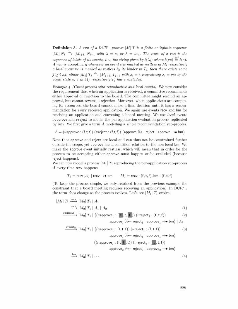
Definition 3. A run of a DCR∗ process [M ] T is a finite or infinite sequence
[Mi] Niλi−→ [Mi+1] Ni+1 with λ = ei or λ = νei. The trace of a run is the
sequence of labels of its events, i.e., the string given by `(λi) where `(νe)def= `(e).
A run is accepting if whenever an event e is marked as restless in Mi respectivelya local event νe is marked as restless by its binder in Ti, then there exists some
j ≥ i s.t. either [Mj ] Tjλi−→ [Mj+1] Tj+1 with λi = e respectively λi = νe; or the
event state of e in Mj respectively Tj has e excluded.
Example 4 (Grant process with reproductive and local events). We now considerthe requirement that when an application is received, a committee recommendseither approval or rejection to the board. The committee might rescind an ap-proval, but cannot reverse a rejection. Moreover, when applications are compet-ing for resources, the board cannot make a final decision until it has a recom-mendation for every received application. We again use events recv and bm forreceiving an application and convening a board meeting. We use local eventsνapprove and νreject to model the per-application evaluation process replicatedby recv. We first give a term A modelling a single recommendation sub-process.
A = (νapprove : (f,t, t)) (νreject : (f,t, f))(approve %← reject | approve→• bm
)
Note that approve and reject are local and can thus not be constrained furtheroutside the scope, yet approve has a condition relation to the non-local bm. Wemake the approve event initially restless, which will mean that in order for theprocess to be accepting either approve must happen or be excluded (becausereject happens).We can now model a process [M1] T1 reproducing the per-application sub-processA every time recv happens
T1 = recv{A} | recv→• bm M1 = recv : (f, t, f), bm : (f, t, f)
(To keep the process simple, we only retained from the previous example theconstraint that a board meeting requires receiving an application). In DCR∗ ,the term does change as the process evolves. Let’s see [M1] T1 evolve:
[M1] T1recv−−→ [M2] T1 | A1
recv−−→ [M2] T1 | A1 | A2 (1)νapprove1−−−−−−→ [M2] T1 |
((νapprove1 : ( t , t, f )) (νreject1 : (f, t, f)) (2)
approve1 %← reject1 | approve1 →• bm)| A2
νreject2−−−−→ [M2] T1 |((νapprove1 : (t, t, f)) (νreject1 : (f, t, f)) (3)
approve1 %← reject1 | approve1 →• bm)
((νapprove2 : (f, f , t)) (νreject2 : ( t , t, f))
approve2 %← reject2 | approve2 →• bm)
bm−−→ [M3] T1 | · · · (4)
228

Here M2 = recv : ( t , t, f), bm : (f, t, f) and M3 = recv : (t, t, f), bm : ( t , t, f).At (1), the processes A1 and A2 are copies of A where the local events approve
and reject have been α-converted to approve1, approve2 and reject1, reject2 respec-tively, following the convention of unique local names. Moreover, because theyhave not happened in the local markings under the binders, bm cannot happen.To see this, observe that by the [par]-rule, for the whole process to exhibit bm,every part of it must also exhibit bm. But (νapprove1 : (f, t, t)) . . . approve1 →•bm cannot: the hypothesis of rule [Local], that bm could happen if approve1 isconsidered global with marking (f, t, t), cannot be established.
When a local approvei event happens, its local marking changes to reflect thatthe event happened and is no longer restless, as indicated with grey backgroundin (2). However, approve1 happening is not enough to enable bm; it is still disabledby the other copy. Also, the entire process is not in an accepting state, sinceapprove2 is still restless and included. Once reject happens in the second copy(3), excluding approve in that copy, bm is enabled and the process is in anaccepting state: of the two local approve events bm is conditional upon, one hashappened (and thus also no longer restless), and the other is excluded (and thusalso no longer required for acceptance).
ut
4 Run-time adaptation by composition
In this section, we consider run-time adaptation by dynamic composition. Thesection ends with the first main technical result of the paper (Theorem 2), thatwe can find a (practically useful and) decidable approximation to adaptationsthat preserve compliancy with existing requirements.
Definition 4. Given DCR∗ processes [M ] T and [N ] S their merge is definedwhen M ⊕N is, in which case it is [M ] T ⊕ [N ] S = [M ⊕N ] T | S. When themerge of two processes is defined, we say that they are marking compatible.
Example 5. Suppose now as the grant process runs, a new requirement comesup: For regulatory reasons, a board meeting must eventually be followed by anaudition. We easily model this constraint using restlessness and a new event,audit. However, as we are introducing a new event, we must also introduce ad-ditional marking. The following process R1 embodies the adaptation we wish toachieve.
R1 = [bm : (f, t, f), audit(f, t, f)] audit←• bm
We can now adapt the process P = [M1] T1 of Example 4 with respect to R1:
P1 = P ⊕R1 = [M1, audit : (f, t, f)] T1 | audit←• bm
Note that adaptation is not restricted to apply only to the initial process. As asecond example, suppose further that it is also decreed that during an audit, no
229
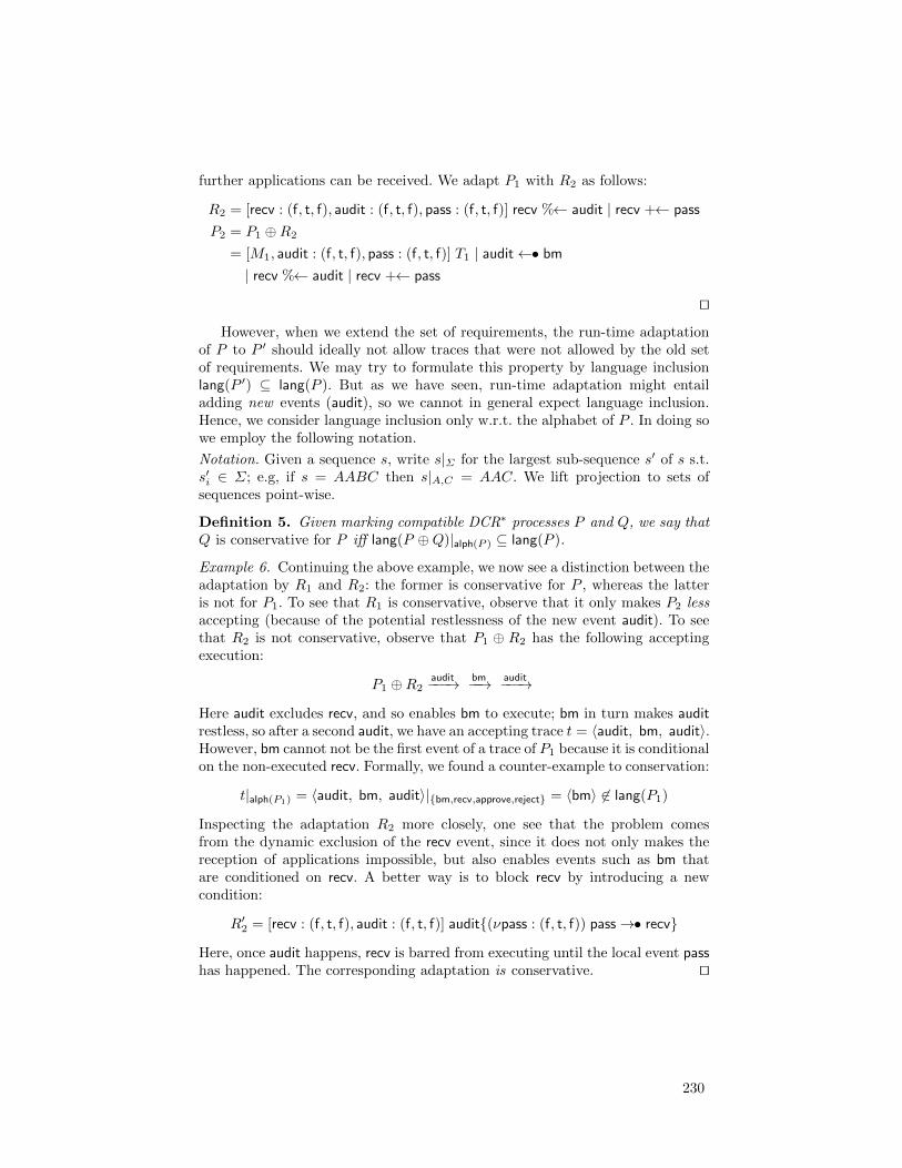
further applications can be received. We adapt P1 with R2 as follows:
R2 = [recv : (f, t, f), audit : (f, t, f), pass : (f, t, f)] recv %← audit | recv +← pass
P2 = P1 ⊕R2
= [M1, audit : (f, t, f), pass : (f, t, f)] T1 | audit←• bm| recv %← audit | recv +← pass
utHowever, when we extend the set of requirements, the run-time adaptation
of P to P ′ should ideally not allow traces that were not allowed by the old setof requirements. We may try to formulate this property by language inclusionlang(P ′) ⊆ lang(P ). But as we have seen, run-time adaptation might entailadding new events (audit), so we cannot in general expect language inclusion.Hence, we consider language inclusion only w.r.t. the alphabet of P . In doing sowe employ the following notation.
Notation. Given a sequence s, write s|Σ for the largest sub-sequence s′ of s s.t.s′i ∈ Σ; e.g, if s = AABC then s|A,C = AAC. We lift projection to sets ofsequences point-wise.
Definition 5. Given marking compatible DCR∗ processes P and Q, we say thatQ is conservative for P iff lang(P ⊕Q)|alph(P ) ⊆ lang(P ).
Example 6. Continuing the above example, we now see a distinction between theadaptation by R1 and R2: the former is conservative for P , whereas the latteris not for P1. To see that R1 is conservative, observe that it only makes P2 lessaccepting (because of the potential restlessness of the new event audit). To seethat R2 is not conservative, observe that P1 ⊕ R2 has the following acceptingexecution:
P1 ⊕R2audit−−−→ bm−−→ audit−−−→
Here audit excludes recv, and so enables bm to execute; bm in turn makes auditrestless, so after a second audit, we have an accepting trace t = 〈audit, bm, audit〉.However, bm cannot not be the first event of a trace of P1 because it is conditionalon the non-executed recv. Formally, we found a counter-example to conservation:
t|alph(P1) = 〈audit, bm, audit〉|{bm,recv,approve,reject} = 〈bm〉 6∈ lang(P1)
Inspecting the adaptation R2 more closely, one see that the problem comesfrom the dynamic exclusion of the recv event, since it does not only makes thereception of applications impossible, but also enables events such as bm thatare conditioned on recv. A better way is to block recv by introducing a newcondition:
R′2 = [recv : (f, t, f), audit : (f, t, f)] audit{(νpass : (f, t, f)) pass→• recv}
Here, once audit happens, recv is barred from executing until the local event passhas happened. The corresponding adaptation is conservative. ut
230
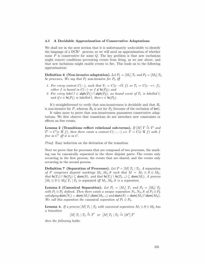
4.1 A Decidable Approximation of Conservative Adaptations
We shall see in the next section that it is unfortunately undecidable to identifythe language of a DCR∗ process, so we will need an approximation of whethersome P is conservative for some Q. The key problem is that new exclusionsmight remove conditions preventing events from firing, as we saw above, andthat new inclusions might enable events to fire. This leads us to the followingapproximation:
Definition 6 (Non-invasive adaptation). Let P1 = [M1] T1 and P2 = [M2] T2be processes. We say that P1 non-invasive for P2 iff
1. For every context C(−), such that T1 = C(e →% f) or T1 = C(e →+ f),either f is bound in C(−) or f 6∈ fe(P2); and
2. For every label l ∈ alph(P1) ∩ alph(P2), no bound event of T1 is labelled l,and if e ∈ fe(P1) is labelled l, then e ∈ fe(P2).
It’s straightforward to verify that non-invasiveness is decidable and that R1
is non-invasive for P , whereas R2 is not for P2 (because of the exclusion of bm).It takes more to prove that non-invasiveness guarantees conservative adap-
tations. We first observe that transitions do not introduce new constraints oreffects on free events.
Lemma 2 (Transitions reflect relational sub-terms). If [M ] Tλ−→ T ′ and
T ′ = C ′(e R f), then there exists a context C(−,−) s.t. T = C(e R f) with ffree in C ′ iff it is in C.
Proof. Easy induction on the derivation of the transition.
Next we prove that for processes that are composed of two processes, the mark-ing can be canonically separated in the three disjoint parts: The events onlyoccurring in the first process, the events that are shared, and the events onlyoccurring in the second process.
Definition 7 (Separation of Processes). Let P = [M ] T1 | T2. A separationof P comprises disjoint markings M1,M2, S such that M = M1 ⊕ S ⊕ M2,that fe(T1) ∩ fe(T2) ⊆ dom(S), and that fe(Ti) \ fe(T3−i) ⊆ dom(Mi). A process[M1 ⊕ S ⊕M2] T1 | T2 is separated iff M1,M2, S is a separation.
Lemma 3 (Canonical Separation). Let P1 = [M1] T1 and P2 = [M2] T2with P1⊕P2 defined. Then there exists a unique separation N1, N2, S of P1⊕P2
satisfying dom(Ni) = dom(Mi)\dom(M3−i) and dom(S) = dom(M1)∩dom(M2).We call this separation the canonical separation of P1 ⊕ P2.
Lemma 4. If a process [M ] T1 | T2 with canonical separation M1⊕S ⊕M2 hasa transition
[M ] T1 | T2 λ−→ T ′ or [M ] T1 | T2 γ−→ [M ′] T ′
then the following holds:
231

1. For some T ′1, T′2 we have T ′ = T ′1 | T ′2.
2. There exists a unique separation M ′1,M′2, S′ of M ′ with dom(Mi) = dom(M ′i)
and dom(S) = dom(S′).3. This separation satisfies alph([Mi ⊕ S] Ti) = alph([M ′i ⊕ S′] T ′i )4. If the original separation was canonical for P1 = [M1 ⊕ S] T1 and P2 =
[S ⊕M2] T2, then so is M ′1,M′2, S′ for P ′1 = [M ′1 ⊕ S′] T ′1 and P ′2 = [S′ ⊕M ′2] T ′2.
5. If P non-invasive for Q, then also P ′ non-invasive for Q′.
Proof. Note that only the rules [par] and [par-2] allows term transitions for aterm on the form T1 | T2; part 1 is then immediate by inspection of these rules;and part 2 and 3 follows from Lemma 1. Part 4 is then immediate from parts 2and 3. Part 5 follows (1) by Lemma 2 and (2) by parts (2–4) and Lemma 1.
We will need the following auxiliary ordering on markings with identicaldomains: Smaller markings have more restless events.
Definition 8. We order states (h, i, r) v (h′, i′, r′) iff h = h′, i = i′ and r′ = timplies r = t. We order markings M v N point-wise when dom(M) = dom(N).
Lemma 5. If M v N and both [M ] T and [N ] T are processes, then:
1. [M ] T ` e : δ iff [N ] T ` e : δ;
2. [M ] Tλ−→ T ′ iff [N ] T
λ−→ T ′; and
3. For every process transition [M ] Tγ−→ [M ′] T ′, there exists a unique N ′
s.t. [N ] Tγ−→ [N ′] T ′. This N ′ satisfies M ′ v N ′.
Proof. Part 1 is immediate by Definition of “`”. Part 2 then follows by inductionon the derivation of the term transition, using part 1 in the base case [Intro].Part 3 follows by cases on the process transition rules [Effect] and [Effect-2],observing that for any M v N and any event or effect x, x ·M v x ·N .
Lemma 6. Both term and process transitions are unique in the following sense:
1. If [M ] Tγ:δ−−→ T ′ and [M ] T
γ:δ′−−→ T ′′ then δ = δ′ and T ′ = T ′′.2. If P
γ−→ Q and Pγ−→ Q′ then Q = Q′.
Proof. (1) By induction on the derivation of the transition. For the base case,[intro], by assumption we have
[M ⊕N ] Te:δ−−→ T and [M ′ ⊕N ′] T e:δ′−−→ T ,
with M ⊕N = M ′ ⊕N ′ and [M ] T ` e : δ and [M ′] T ` e : δ′. We now find bycases on T and inspection of the rules in Figure 4 that M = M ′ and δ = δ′.
The cases [par], [par-2], and [rep] cases are straightforward; we exemplify
with [par-2]. Suppose [M ] T | U νe:δ1−−−→ T1 and [M ] T | U νe:δ2−−−→ T2. By [par-2]
we must have T1 = T ′1 | U and T2 = T ′2 | U , and moreover [M ] Tνe:δ1−−−→ T ′1 and
[M ] Tνe:δ2−−−→ T ′2. But then by IH δ1 = δ2 and T ′1 = T ′2 whence T1 = T2.
232
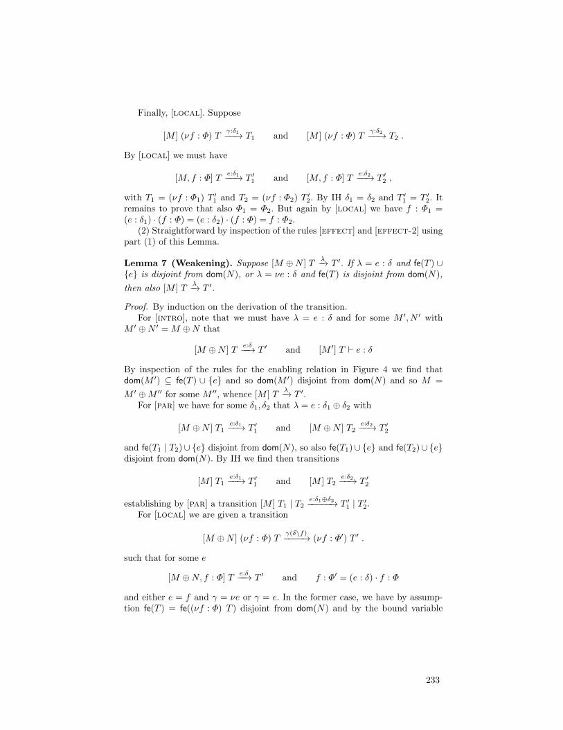
Finally, [local]. Suppose
[M ] (νf : Φ) Tγ:δ1−−→ T1 and [M ] (νf : Φ) T
γ:δ2−−→ T2 .
By [local] we must have
[M,f : Φ] Te:δ1−−→ T ′1 and [M,f : Φ] T
e:δ2−−→ T ′2 ,
with T1 = (νf : Φ1) T ′1 and T2 = (νf : Φ2) T ′2. By IH δ1 = δ2 and T ′1 = T ′2. Itremains to prove that also Φ1 = Φ2. But again by [local] we have f : Φ1 =(e : δ1) · (f : Φ) = (e : δ2) · (f : Φ) = f : Φ2.
(2) Straightforward by inspection of the rules [effect] and [effect-2] usingpart (1) of this Lemma.
Lemma 7 (Weakening). Suppose [M ⊕N ] Tλ−→ T ′. If λ = e : δ and fe(T ) ∪
{e} is disjoint from dom(N), or λ = νe : δ and fe(T ) is disjoint from dom(N),
then also [M ] Tλ−→ T ′.
Proof. By induction on the derivation of the transition.For [intro], note that we must have λ = e : δ and for some M ′, N ′ with
M ′ ⊕N ′ = M ⊕N that
[M ⊕N ] Te:δ−−→ T ′ and [M ′] T ` e : δ
By inspection of the rules for the enabling relation in Figure 4 we find thatdom(M ′) ⊆ fe(T ) ∪ {e} and so dom(M ′) disjoint from dom(N) and so M =
M ′ ⊕M ′′ for some M ′′, whence [M ] Tλ−→ T ′.
For [par] we have for some δ1, δ2 that λ = e : δ1 ⊕ δ2 with
[M ⊕N ] T1e:δ1−−→ T ′1 and [M ⊕N ] T2
e:δ2−−→ T ′2
and fe(T1 | T2)∪ {e} disjoint from dom(N), so also fe(T1)∪ {e} and fe(T2)∪ {e}disjoint from dom(N). By IH we find then transitions
[M ] T1e:δ1−−→ T ′1 and [M ] T2
e:δ2−−→ T ′2
establishing by [par] a transition [M ] T1 | T2 e:δ1⊕δ2−−−−−→ T ′1 | T ′2.For [local] we are given a transition
[M ⊕N ] (νf : Φ) Tγ(δ\f)−−−−→ (νf : Φ′) T ′ .
such that for some e
[M ⊕N, f : Φ] Te:δ−−→ T ′ and f : Φ′ = (e : δ) · f : Φ
and either e = f and γ = νe or γ = e. In the former case, we have by assump-tion fe(T ) = fe((νf : Φ) T ) disjoint from dom(N) and by the bound variable
233
convention we may assume e = f also not in the domain of dom(N). Hence
fe(T ) ∪ {e = f} also disjoint from N and by IH we have [M,f : Φ] Te:δ−−→ T ′
which by [local] yields the requisite transition. In the latter case, we have be-cause γ = e that fe(T ) ∪ {e} = fe(f{Φ}T ) ∪ {e} disjoint from N and again byIH we find the requisite transition.
Finally, the cases [rep] and [par-2] are straightforward applications of IH,noting for the former that fe(T ) = fe(e{T}) and for the latter that fe(T ) ⊆fe(T | U) and so in both cases disjointness with N is preserved as we move tothe hypothesis.
Lemma 8. If [M ] Tγ:δ−−→ T ′ with δ = (X, I,R) then e ∈ X resp. e ∈ I implies
T = C(f →% e) resp. T = C(f →+ e) with e not bound in C(−).
Proof. Easy induction on the derivation of the transition.
Lemma 9. Let P be non-invasive for Q, and suppose M1, S,M2 is the canonical
separation of P ⊕Q = [M1 ⊕ S ⊕M2] T1 | T2. If also [M1 ⊕ S ⊕M2] T1γ:δ−−→ T ′1
with δ = (X, I,R), then X, I are both disjoint from fe(Q).
Proof. Immediate from the Definition of non-invasiveness and Lemma 8.
Lemma 10. Let P be non-invasive for Q, and suppose M1, S,M2 is the canoni-
cal separation of P⊕Q = [M1 ⊕ S ⊕M2] T1 | T2. If also [M1 ⊕ S ⊕M2] T1 | T2 γ:δ−−→T ′1 | T ′2 then the following are true.
1. If `(γ) ∈ alph(Q) then for some δ′ we have [S ⊕M2] T2γ:δ′−−→ T ′2 and (γ : δ) ·
(S ⊕M2) v (γ : δ′) · (S ⊕M2).2. If `(γ) 6∈ alph(Q) then (γ : δ) · (S ⊕M2) v S ⊕M2.
Proof. We proceed by cases on γ; suppose first γ = νe. If νe is a binder ofT2, we must have `(γ) ∈ alph(Q) and the transition must arise by (the rulesymmetric to) [par-2]. By definition of canonical separation we have fe(T2) dis-
joint from dom(M1) and so by Lemma 7 we find a transition [S ⊕M2] T2νe:δ−−→
T ′2, altogether establishing (1). If instead νe is a binder of T1, we must have`(γ) 6∈ alph(Q) lest non-invasiveness be contradicted. In that case we must havea transition
[M1 ⊕ S ⊕M2] T1νe:δ−−→ T ′1
by Lemma 9 we find (γ : δ) · (S ⊕M2) v S ⊕M2.Suppose instead γ = e. In this case the transition must be derived by [par],
and so by Lemma 6 there exists unique δ1, δ2 such that
[M1 ⊕ S ⊕M2] T1e:δ1−−→ T ′1 and [M1 ⊕ S ⊕M2] T2
e:δ2−−→ T ′2
Suppose for (1) that `(e) ∈ alph(Q). By non-invasiveness and canonicity of sepa-ration we then have that e 6∈ dom(M1) and that fe(T2) is disjoint from dom(M1),and so by Lemma 7 we have a transition
[S ⊕M2] T2e:δ2−−→ T ′2
234
By Lemma 9 it now follows that (e : δ1 ⊕ δ2) · (S ⊕M2) v (e : δ2) · (S ⊕M2).Suppose instead for (2) that `(e) 6∈ alph(Q). It follows that e 6∈ fe(T2), and soδ2 = (∅, ∅, ∅). We now find (γ : δ) · (S ⊕M2) v S ⊕M2 by Lemmas 7 and 9.
Lemma 11. Let P be non-invasive for Q, and suppose M1, S,M2 is the canoni-
cal separation for P⊕Q = [M1 ⊕ S ⊕M2] T1 | T2. If also [M1 ⊕ S ⊕M2] T1 | T2 γ−→[M ′1 ⊕ S′ ⊕M ′2] T ′1 | T ′2 = R where the latter is also a canonical separated thenthe following are true.
1. If `(γ) ∈ alph(Q) then [S ⊕M2] T2γ−→ [N ] T ′2 where S′ ⊕M ′2 v N .
2. If `(γ) 6∈ alph(Q) then S′ ⊕M ′2 v S ⊕M2.
Proof. Immediate from the preceding Lemma and rules [effect] and [effect-2].
We are now finally ready for the first main technical result of the paper: Thatthe syntactically decidable non-invasiveness property implies conservation.
Theorem 2. If P is non-invasive for Q then P is conservative for Q.
Proof. Let M = M1⊕S⊕M2 be the canonical separation of P ⊕Q, and considera finite or infinite run of R0 = P ⊕Q = [M ] T1 | T2:
R0γ0−→ R1
γ1−→ . . .
By induction on i using Lemma 4, we can write eachRi as a canonically separatedprocess
Ri = [M i1 ⊕ Si ⊕M i
2] T i1 | T i2 = ([M i1 ⊕ Si] T i1)⊕ ([M i
2 ⊕ Si] T i2)
where alph([M i1 ⊕ Si] T i1) = alph(P ) and alph([Si ⊕M i
2] T i2) = alph(Q), and[M i
1] T i1 is non-invasive for [M i2] T i2. We prove by induction that there exists
a sequence N i satisfying (a) N0 = S0 ⊕M02 , (b) Si ⊕M i
2 v N i, and (c)
N i+1 = N i when `(γi) 6∈ alph(Q)
[N i] T i2γi−→ [N i+1] T i+1
2 when `(γi) ∈ alph(Q)
The Theorem then follows. We have immediately N0, obtaining (a). For (b) and(c), consider some i > 0, and assume first `(γi) 6∈ alph(Q). By Lemma 11, Part2, we then have Si+1 ⊕Mi+1 v Si ⊕Mi v Ni = Ni+1, obtaining (b) and (c).Assume instead `(γi) ∈ alph(Q). Then take N i+1 = N where N is given byLemma 11, Part 1, immediately obtaining (b) and (c).
5 Turing completeness of DCR∗
In this section we show that DCR∗ has the full power of Turing machines byreduction from the Halting Problem for Minsky machines [28]. This is in contrastto the fact that the DCR process language of Section 2 can be shown (essentially
235

via encoding to and from Buchi-automata) to characterise exactly languages thatare the union of a regular and an ω-regular language.4
A Minsky machine m = (R1, R2, P, c) comprises two unbounded registersR1, R2; a program P , which is a list of pairs of addresses and instructions; anda program counter c, giving the address of the current instruction. It has thefollowing instruction set.
inc(i, a) Add 1 to the contents of register i. Proceed to a.
decjz(i, a, b) If register i is zero, proceed to a. Otherwise subtract 1 fromregister i and proceed to b.
halt Halt execution (wlog assumed to appear exactly once).
We construct, given a Minsky machine m, a term t(m) and a marking m(m).We model machine instructions as events. To maintain execution order, we modelprogram addresses explicitly as events a. These events serve only to constrainthe execution of other events; they should not themselves happen, and we pre-vent them from doing so with a condition a →• a for each a. By making eachinstruction event e conditional on its program point a, a →• e, we ensure thatonly if a is excluded may e happen. To move the program counter from a to b, were-include a and exclude b. We define a shorthand insn(e, a, b) for an instructionevent e at program point a proceeding to program point b as follows:
insn(e, a, b) = a→• e | a +← e | b %← e
Now, registers. We model each a : decjz(i, b, c) by two events: one, decjza,which can happen only when the register is zero, and a second, decjna, whichcan happen only when it is not. Then we model increments by making eachincrement reproductive, replicating a new copy of decjna for every decrementinstruction a : decjz(i, b, c) in P . The copies produced by a single incrementrepresents the opportunity for exactly one of these instructions to decrement.Thus, we make the copies in a single increment exclude each other. To makesure that decjza cannot happen if the register is non-zero, that is, if no decjna
is present, we make the latter a condition of the former: decjna →• decjza.Altogether, the term for one increment is constructed by the following function.(We write (Ni∈Ixi : M) for (νxi1 : M) . . . (νxin : M) when I = {i1, . . . , in}.)
one(i) =(
Na:decjz(i,c,d)
decjna : (f,t, f)) ∏
a:decjz(i,c,d)
(insn(decjna, a, d) |
decjna →• decjza |∏
a′:decjz(i,b′,c′)
decjna′
%← decjna)
Adding one to a register i is accomplished by making a new copy of one(i).
inc(a, i, b) = insn(inca, a, b) | inca{one(i)}4 This result is similar to the expressiveness result for DCR Graphs sketched in [30],
and can be found in the full version [11].
236

We put it all together and define t(m) for a Minsky machine m = (R1, R2, P, c).
t(m) =∏
a:inc(i,b)∈Pinc(a, i, b) |
∏
a:decjz(i,b,c)∈Pinsn(decjza, a, b)
|∏
a:halt∈Pa→• halt |
∏
a:I∈Pa→• a |
∏
i<R1
one(1) |∏
i<R2
one(2)
Finally, the marking m(m) is given below. (Recall that c is the program counter.)
c a when a 6= c decjza inca haltHappened f f f f f
Included f t t t tRestless f f f f t
Example 7. As an example, let us consider a Minsky machine adding the con-tents of register 2 to register 1. We’ll consider the machine (0, 1, P, 1), where Pis the program:
1 : decjz(2, 3, 2)2 : inc(1, 1)3 : halt
Applying the above construction, we get the following term (split out in atable for readability).
∏
a:inc(i,b)∈Pinc(a, i, b)
∏
a:decjz(i,b,c)∈Pinsn(decjza, a, b)
2→• inc2 1→• decjz12 %← inc2 1 +← decjz1
1 +← inc2 3 %← decjz1
inc2{0}∏
a:halt∈Pa→• halt
∏
a:I∈Pa→• a
∏
i<R1
one(1)∏
i<R2
one(2)
3→• halt 1→• 1 0 (νdecjn1 : (f,t, f))2→• 2 1→• decjn13→• 3 1 +← decjn1
2 %← decjn1
decjn1 →• decjz1decjn1 %← decjn1
We emphasise that in the column Πi<R2one(2), all instances of decjn1 are within
the scope of the binder and thus local. ut
Theorem 3. A Minsky machine m halts iff [m(m)] t(m) has an accepting run.
Proof. (Sketch) The proof is based on a bisimulation relation between finite ex-ecution traces of the Minsky machine m and reachable markings of the encoding[m(m)] t(m). First we observe that in every reachable marking of [m(m)] t(m)
237

exactly one of the program address events will be included and exactly one eventis enabled. The bisimulation relation will relate an execution trace of the Minskymachine ending in address j to a marking in which that event is excluded. Nextwe prove that for every pair, the machine can perform an instruction iff theencoding can execute the corresponding event, and that the form of the processt(m) is preserved as well as the global marking m(m), except that instructionevents are being recorded as executed (and excluded in the case of decjn) ispreserved by steps. It follows that the restless halt event can be eventuallyexecuted if and only if the machine can execute the halt command.
6 Conclusion, Related and Future Work
We first presented the constraint-based Dynamic Condition Response (DCR)language, which generalises event structures using the notions of dynamic in-clusion and exclusion of events, and conditions and responses introduced in ourwork on DCR Graphs. We provided a compositional semantics for the DCRlanguage and noted that it provides a term language for (modular definitionof) DCR Graphs. We then extended the DCR language to the DCR∗ language,allowing dynamic creation of sub processes with (fresh) local events. This exten-sion was inspired by the recent extension of DCR Graphs to hierarchical DCRGraphs [12], which is motivated in practice and exemplified in the paper by agrant application process, in which each grant application needs an independentdecision of accept or reject. As the next contribution we introduced a notionof run-time adaptation by composition for DCR∗ and formalised when an adap-tation is conservative, i.e. preserves the constraints of the adapted process. Asa key technical result, we provided a decidable approximation to conservativeadaptation referred to as non-intrusive adaptations. We illustrated that non-intrusive adaptation is useful in practice by showing examples, and also showinghow an intrusive adaptation could be replaced by a non-intrusive one. As thefinal technical contribution we proved that the DCR∗ language is Turing com-plete. This also means that the notion of conservative adaptation is undecidable,and thus establish the importance of the decidable approximation. The Turingcompleteness result should be seen in contrast to the fact that the DCR processlanguage corresponds to the DCR graphs model, which is known to characteriseexactly languages that are the union of a regular and an ω-regular language.
Related Work. As the DCR language is essentially a term language for DCRGraphs [30,36,18]; which in turn is a descendant of event structures that areclosely related to Petri Nets, DCR processes are also naturally related to PetriNets. Petri Nets have been extended to allow modular definition (e.g. via sharedtransitions [27]) and to represent infinite computations and ω-regular languages(e.g. Buchi Net [15]). However, as mentioned in the introduction, Petri net in-troduces the intentional construct of places marked with tokens, as opposed toevent structures and DCR∗ processes only relying on causal and conflict relationsbetween events. A number of variants of event structures with asymmetric con-flict relation related to the asymmetric exclude relation of DCR processes have
238

been proposed, including extended bundle event structures [25,17], dual eventstructures [24,26], asymmetric event structures [6], and precursor event struc-tures [16]. Automata based models like Event automata [33] and local eventstructures [21] also allows for asymmetric conflicts, but they introduce the no-tion of states explicitly and do not express the notion of causality and conflictsas relations between events. Besides the early work on restless events in [37], weare not aware of other published work generalising event-structures to be able toexpress liveness properties or to distinguish between events that may and eventsthat must eventually be executed. Reproductive events of the DCR∗ process lan-guage relate to replication in process calculi and higher-order Petri nets [23]. Weare not aware of other work combining such higher-order features and liveness.
Run-time adaptation is emerging as an important topic in many branches ofcomputer science. Much previous work dealt with imperative process notationssuch as Petri nets [35] and process calculi [5,8,9] requiring predefined adapta-tion points and often dealing with adaptations via higher-order primitives. Incontrast, adaptation in DCR∗ is dealt with by composition, which due to thedeclarative nature allow for cross-cutting adaptations without the need for pre-specified adaptation points.
Within the BPM community, interest in declarative languages arose with thework on Declare [4,1]. Declare is in essence a template language, consisting oftypical constraints encountered in business processes which are given a formalsemantics by mapping them to LTL formulae. In contrast to DCR Graphs, wherethere is a close connection between the design-time and run-time of a model, theexecution and analysis of Declare models relies on a mapping to LTL and then toautomata (in fact, Declare semantics only consider finite executions). Addition-ally Declare has a relatively large set of basic constraints, for which the formalexpressiveness is still an open question, but is clearly limited to at most thatof LTL, while DCR Graphs with only 4 basic constraints offers the full expres-siveness of regular and ω-regular languages. As another alternative [29] providesa mapping from Declare constraints to the CLIMB Computational Logic-basedlanguage, which allows the use of its reasoning techniques for support and veri-fication of Declare processes at design- and run-time.
More recently the Guard-Stage-Milestone (GSM) approach [22] has been de-veloped at IBM Research, which offers a data-centric business process modellingnotation. The notation consists of stages, which have guards controlling whenthe stage may start, and milestones controlling when and how a stage may close.While the guards and milestones give a declarative flavour to the notation, itis still mainly data-centric, whereas DCR is mainly focussed on describing theevents (or activities) of the system and the relations between them.
While imperative process models such as BPMN [32] have supported dy-namic sub-processes for some time now, they are only recently being studiedfor declarative languages [39]. In most cases, there is a tendency to emphasisesub-processes that do not have independent life cycles, that is, a sub processesis spawned, and must run to completion before the super process may resume;this includes [39]. Interestingly, it is noted in ibid. that extending the model with
239

sub-processes seems to increase its expressive power; we formally confirm thatsupposition here, finding DCR graphs with sub-processes to be Turing complete.
Future work. The work opens several interesting paths for future work. Firstly,the DCR∗ processes as defined only interact via shared events. We are currentlyworking on adding interaction between concurrent events, labelled with sendand receive labels as found e.g. in the π-calculus, thereby lifting the results ofthe present paper to π-like languages. In relation to that, we also work on ex-ploring independence model (also referred to as true-concurrency) semantics ofDCR∗ processes, which benefits from the explicit definition of events in DCR∗
processes. An independence model semantics could support partial order ver-ification techniques and refinement of events. We have also initiated work onexploiting the idea of responses and restless events in the domain of behaviouraltypes [13] and run-time monitoring [30], which provides an avenue for analysinginfinite-state systems. Along another path, we have in [10] initiated an explo-ration of branching simulations between transition systems with responses, ageneralisation of the LTS-with-acceptance of Def. 1, which we believe will gener-alise modal transition systems and refinement to models expressing more generalliveness properties. The next step from that exploration will be to investigatebranching bisimulation congruences. The DCR∗ process language should alsobe formally related to the hierarchical DCR Graphs introduced in [12] and therelation to modular [27] and higher-order Petri Nets [23] should be investigated.We conjecture that DCR∗ and hierarchical DCR Graphs are equivalent, butthe mapping is not as straightforward as the one between basic DCR processesand Graphs. Finally, time constraints and more general adaptations as initi-ated in [20,31], e.g. allowing to remove constraints and events should be furtherinvestigated.
Acknowledgments. We thank the anonymous reviewers for helpful comments.
References
1. van der Aalst, W., Pesic, M., Schonenberg, H., Westergaard, M., Maggi, F.M.:Declare. Webpage (2010), http://www.win.tue.nl/declare/
2. van der Aalst, W.M.P.: The application of petri nets to workflow management.Journal of Circuits, Systems, and Computers 8(1), 21–66 (1998)
3. van der Aalst, W.M.P., ter Hofstede, A.H.M., Weske, M.: Business process man-agement: A survey. In: van der Aalst, W.M.P., ter Hofstede, A.H.M., Weske, M.(eds.) Business Process Management, International Conference, BPM 2003, Eind-hoven, The Netherlands, June 26-27, 2003, Proceedings. Lecture Notes in Com-puter Science, vol. 2678, pp. 1–12. Springer (2003), http://dx.doi.org/10.1007/3-540-44895-0_1
4. van der Aalst, W.M., Pesic, M.: DecSerFlow: Towards a truly declarative serviceflow language. In: WS-FM 2006. LNCS, vol. 4184, pp. 1–23. Springer (2006)
5. Anderson, G., Rathke, J.: Dynamic software update for message passing programs.In: Jhala, R., Igarashi, A. (eds.) APLAS. Lecture Notes in Computer Science, vol.7705, pp. 207–222. Springer (2012)
6. Baldan, P., Corradini, A., Montanari, U.: Contextual petri nets, asymmetric eventstructures, and processes. Information and Computation 171, 1–49 (2001)
240

7. Barthe, G., Pardo, A., Schneider, G. (eds.): Software Engineering and FormalMethods - 9th International Conference, SEFM 2011, Montevideo, Uruguay,November 14-18, 2011. Proceedings, LNCS, vol. 7041. Springer (2011)
8. Bravetti, M., Di Giusto, C., Perez, J.A., Zavattaro, G.: Steps on the road tocomponent evolvability. In: Proceedings of the 7th International Conference onFormal Aspects of Component Software. pp. 295–299. FACS’10 (2012), http:
//dx.doi.org/10.1007/978-3-642-27269-1_19
9. Bravetti, M., Giusto, C.D., Perez, J.A., Zavattaro, G.: Adaptable processes. LogicalMethods in Computer Science 8(4) (2012)
10. Carbone, M., Hildebrandt, T.T., Perrone, G., Wasowski, A.: Refinement for tran-sition systems with responses. In: FIT. EPTCS, vol. 87, pp. 48–55 (2012)
11. Debois, S., Hildebrandt, T., Slaats, T.: Towards a foundation for modular run-timeadaptable process-aware information systems (full version), http://www.itu.dk/
~hilde/dcrpl-full.pdf
12. Debois, S., Hildebrandt, T.T., Slaats, T.: Hierarchical declarative modelling withrefinement and sub-processes. In: Business Process Management - 12th Inter-national Conference, BPM 2014, Haifa, Israel, September 7-11, 2014. Proceed-ings. Lecture Notes in Computer Science, vol. 8659, pp. 18–33. Springer (2014),http://dx.doi.org/10.1007/978-3-319-10172-9_2
13. Debois, S., Hildebrandt, T.T., Slaats, T., Yoshida, N.: Type checking liveness forcollaborative processes with bounded and unbounded recursion. In: FORTE. Lec-ture Notes in Computer Science, vol. 8461, pp. 1–16. Springer (2014)
14. Debois, S., Hildebrandt, T., Marquard, M., Slaats, T.: A case for declarative processmodelling: Agile development of a grant application system. In: 3nd InternationalWorkshop on Adaptive Case Management and other non-workflow approaches toBPM (AdaptiveCM 2014) (2014)
15. Esparza, J., Melzer, S.: Model checking ltl using constraint programming. In:Azema, P., Balbo, G. (eds.) Application and Theory of Petri Nets 1997, LectureNotes in Computer Science, vol. 1248, pp. 1–20. Springer Berlin Heidelberg (1997),http://dx.doi.org/10.1007/3-540-63139-9_26
16. Fecher, H., Majster-Cederbaum, M.: Event structures for arbitrary disruption. Fun-dam. Inf. 68(1-2), 103–130 (Apr 2005)
17. van Glabbeek, R., Vaandrager, F.: Bundle event structures and ccsp. In: Ama-dio, R., Lugiez, D. (eds.) CONCUR 2003 - Concurrency Theory, Lecture Notesin Computer Science, vol. 2761, pp. 57–71. Springer Berlin Heidelberg (2003),http://dx.doi.org/10.1007/978-3-540-45187-7_4
18. Hildebrandt, T.T., Mukkamala, R.R.: Declarative event-based workflow as dis-tributed dynamic condition response graphs. In: PLACES. EPTCS, vol. 69, pp.59–73 (2010)
19. Hildebrandt, T.T., Mukkamala, R.R., Slaats, T.: Nested dynamic condition re-sponse graphs. In: FSEN. LNCS, vol. 7141, pp. 343–350. Springer (2011)
20. Hildebrandt, T.T., Mukkamala, R.R., Slaats, T., Zanitti, F.: Contracts for cross-organizational workflows as timed dynamic condition response graphs. J. Log.Algebr. Program. 82(5-7), 164–185 (2013), http://dx.doi.org/10.1016/j.jlap.2013.05.005
21. Hoogers, P., Kleijn, H., Thiagarajan, P.: An event structure semantics for generalpetri nets. Theoretical Computer Science 153(1–2), 129 – 170 (1996), http://www.sciencedirect.com/science/article/pii/0304397595001204
22. Hull, R., Damaggio, E., Fournier, F., Gupta, M., Heath, F.T., Hobson, S., Line-han, M.H., Maradugu, S., Nigam, A., Sukaviriya, P., Vaculın, R.: Introducing the
241

guard-stage-milestone approach for specifying business entity lifecycles. In: WS-FM. LNCS, vol. 6551, pp. 1–24. Springer (2010)
23. Janneck, J.W., Esser, R.: Higher-order petri net modelling: Techniques and ap-plications. In: Proceedings of the Conference on Application and Theory of PetriNets: Formal Methods in Software Engineering and Defence Systems. pp. 17–25.CRPIT ’02 (2002), http://dl.acm.org/citation.cfm?id=846335.846338
24. Katoen, J.P.: Quantitative and qualitative extensions of event structures. Ph.D.thesis, University of Twente, Enschede (April 1996)
25. Langerak, R.: Transformations and Semantics for LOTOS. Universiteit Twente(1992), http://books.google.dk/books?id=qB4EAgAACAAJ
26. Langerak, R., Brinksma, E., Katoen, J.P.: Causal ambiguity and partial ordersin event structures. In: Mazurkiewicz, A., Winkowski, J. (eds.) CONCUR ’97:Concurrency Theory, Lecture Notes in Computer Science, vol. 1243, pp. 317–331.Springer Berlin Heidelberg (1997)
27. Latvala, T., Makela, M.: Ltl model checking for modular petri nets. In: Cortadella,J., Reisig, W. (eds.) Applications and Theory of Petri Nets 2004, Lecture Notesin Computer Science, vol. 3099, pp. 298–311. Springer Berlin Heidelberg (2004),http://dx.doi.org/10.1007/978-3-540-27793-4_17
28. Minsky, M.L.: Computation: Finite and Infinite Machines. Prentice-Hall (1967)29. Montali, M.: Specification and Verification of Declarative Open Interaction Models
- A Logic-Based Approach, Lecture Notes in Business Information Processing,vol. 56. Springer (2010)
30. Mukkamala, R.R.: A Formal Model For Declarative Workflows: Dynamic ConditionResponse Graphs. Ph.D. thesis, IT University of Copenhagen (June 2012)
31. Mukkamala, R.R., Hildebrandt, T., Slaats, T.: Towards trustworthy adaptive casemanagement with dynamic condition response graphs. In: EDOC. pp. 127–136.IEEE (2013)
32. Object Management Group BPMN Technical Committee: Business Process Modeland Notation, version 2.0, http://www.omg.org/spec/BPMN/2.0/PDF
33. Pinna, G., Poigne, A.: On the nature of events: another perspective in con-currency. Theoretical Computer Science 138(2), 425 – 454 (1995), http://www.
sciencedirect.com/science/article/pii/030439759400174H, meeting on themathematical foundation of programing semantics
34. Reichert, M., Weber, B.: Enabling Flexibility in Process-Aware Information Sys-tems - Challenges, Methods, Technologies. Springer (2012)
35. Sibertin-Blanc, C., Mauran, P., Padiou, G.: Safe Adaptation of Compo-nent Coordination. Proceedings of the Third International Workshop onCoordination and Adaption Techniques for Software Entities 189, 69–85 (juil-let 2007), http://www.sciencedirect.com/science?_ob=MImg&_imagekey=
B75H1-4P5RTKV-6-1&_cdi=13109&_user=4373277&_orig=browse&_coverDate=
07%252F17%252F2007&_sk=998109999&view=c&w36. Slaats, T., Mukkamala, R.R., Hildebrandt, T.T., Marquard, M.: Exformatics
declarative case management workflows as DCR graphs. In: BPM. LNCS, vol.8094, pp. 339–354. Springer (2013)
37. Winskel, G.: Events in Computation. Ph.D. thesis, University of Edinburgh (1980)38. Winskel, G.: Event structures. In: Advances in Petri Nets. LNCS, vol. 255, pp.
325–392. Springer (1986)39. Zugal, S., Soffer, P., Pinggera, J., Weber, B.: Expressiveness and understandabil-
ity considerations of hierarchy in declarative business process models. In: BM-MDS/EMMSAD. Lecture Notes in Business Information Processing, vol. 113, pp.167–181. Springer (2012)
242

8 Hybrid BPM Technologies
243
Declarative Modeling—An Academic Dream orthe Future for BPM?
Hajo A. Reijers1,2, Tijs Slaats3,4, and Christian Stahl1
1 Department of Mathematics and Computer Science, Technische UniversiteitEindhoven, P.O. Box 513, 5600 MB Eindhoven, The Netherlands
{H.A.Reijers, C.Stahl}@tue.nl2 Perceptive Software, Piet Joubertstraat 4, 7315 AV Apeldoorn, The Netherlands
3 IT University of Copenhagen, Rued Langgaardsvej 7, 2300 Copenhagen, [email protected]
4 Exformatics A/S, Lautrupsgade 13, 2100 Copenhagen, Denmark
Abstract. Declarative modeling has attracted much attention over thelast years, resulting in the development of several academic declarativemodeling techniques and tools. The absence of empirical evaluations ontheir use and usefulness, however, raises the question whether practi-tioners are attracted to using those techniques. In this paper, we presenta study on what practitioners think of declarative modeling. We showthat the practitioners we involved in this study are receptive to the ideaof a hybrid approach combining imperative and declarative techniques,rather than making a full shift from the imperative to the declarativeparadigm. Moreover, we report on requirements, use cases, limitations,and tool support of such a hybrid approach. Based on the gained insight,we propose a research agenda for the development of this novel modelingapproach.
1 Introduction
Imperative modeling is currently the most prominent modeling paradigm inBPM. Imperative modeling techniques are implemented in almost every model-ing tool, and many imperative modeling languages have been developed, mostprominently, Event-Driven Process Chains (EPCs) and Business Process Mod-eling Notation. Imperative models take an “inside-out” approach; that is, everypossible execution sequence must be modeled explicitly. As a consequence, im-perative modeling may lead to over-specification and lack of flexibility, makingit difficult to defer decisions at runtime and to change existing process mod-els [21,2].
To overcome these shortcomings, declarative modeling approaches have beenproposed [3]. In contrast to imperative approaches, declarative models take an“outside-in” approach. Instead of describing how the process has to work ex-actly, only the essential characteristics are described. To this end, constraintsare specified that restrict the possible execution of activities.
244

2
Research on declarative modeling has gained increasing interest over the lastyears. Declarative languages, such as Declare [3] (formerly known as DecSer-Flow), DCR Graphs [12] and SCIFF [14], have been developed. These languageshave been integrated in academic and industrial modeling tools [24].
Beside the development of declarative techniques, also empirical researchhas been conducted to study the relation between imperative and declarativeapproaches [8,9,22,20]. It is well understood how to specify properties of a busi-ness process, but it is still not clear how to define a business process modelinglanguages that is understandable [8] on the one hand, and enables maintainabil-ity [9], expressiveness and modeling comfort, on the other hand.
To the best of our knowledge, there does not exist any studies that reflecton the question whether declarative techniques can be used in practise from apractitioner’s standpoint. This raises a question, which has not been answeredyet: Do practitioners see opportunities to use declarative techniques?
The contribution of this paper is to present what practitioners think of declar-ative modeling. In that way, we close the gap between research on declarativetechniques and empirical investigations on declarative modeling. Our results arebased on a workshop on declarative modeling with ten professionals from in-dustry, including both consultants involved in modeling projects and developersof industrial modeling tools. During the workshop, we introduced declarativemodeling techniques, performed two modeling assignments, and discussed theprospects of a declarative approach. The evaluation, both qualitative and quan-titative, shows that practitioners see good opportunities for a hybrid approachcombining imperative and declarative techniques while they are skeptical regard-ing a purely declarative approach. With the gained insight from the discus-sion, we present requirements on such a hybrid approach, use cases, limitations,and requirements concerning tool support. Shifting the focus from imperativeand declarative modeling to a hybrid approach raises many research questions.Therefore, we propose a research agenda for the BPM community to make thehybrid approach work.
We continue with a brief introduction to Declare and DCR Graphs, twodeclarative approaches we used throughout the workshop. In Sect. 3, we de-scribe the outline of the workshop and our evaluation method. The quantitativeevaluation is described in Sect. 4, and Sect. 5 reports on the qualitative evalua-tion. In Sect. 6, we present our research agenda. We close with a conclusion anddirections for future work.
2 Declare and DCR Graphs by Example
In this section, we briefly introduce two declarative modeling approaches, De-clare [3,24] and DCR Graphs [12], using the following example of a documentmanagement system. To simplify the presentation, we restrict ourselves to thecontrol flow dimension and do not consider data or resources.
Example 1. Every case of the document management system is initially createdand eventually closed. For a created case, an arbitrary number of documents can
245
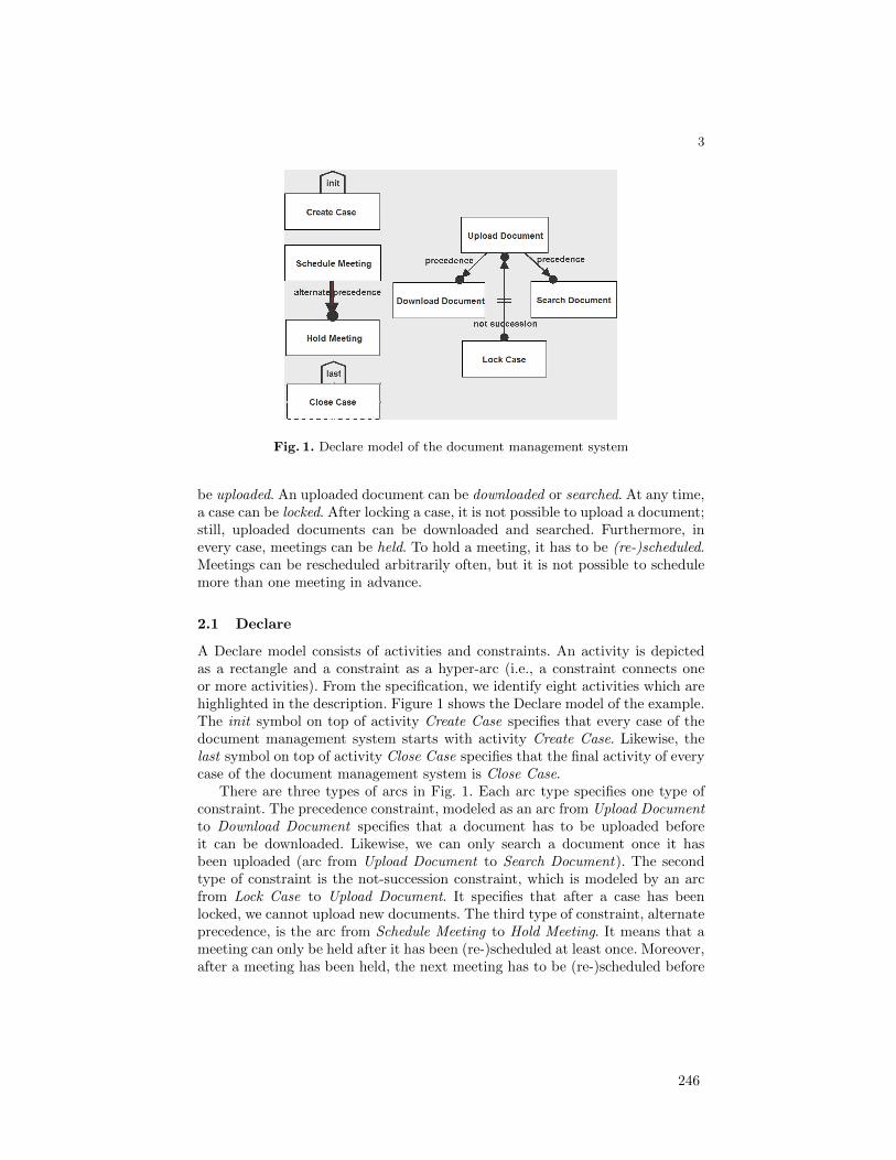
3
Fig. 1. Declare model of the document management system
be uploaded. An uploaded document can be downloaded or searched. At any time,a case can be locked. After locking a case, it is not possible to upload a document;still, uploaded documents can be downloaded and searched. Furthermore, inevery case, meetings can be held. To hold a meeting, it has to be (re-)scheduled.Meetings can be rescheduled arbitrarily often, but it is not possible to schedulemore than one meeting in advance.
2.1 Declare
A Declare model consists of activities and constraints. An activity is depictedas a rectangle and a constraint as a hyper-arc (i.e., a constraint connects oneor more activities). From the specification, we identify eight activities which arehighlighted in the description. Figure 1 shows the Declare model of the example.The init symbol on top of activity Create Case specifies that every case of thedocument management system starts with activity Create Case. Likewise, thelast symbol on top of activity Close Case specifies that the final activity of everycase of the document management system is Close Case.
There are three types of arcs in Fig. 1. Each arc type specifies one type ofconstraint. The precedence constraint, modeled as an arc from Upload Documentto Download Document specifies that a document has to be uploaded beforeit can be downloaded. Likewise, we can only search a document once it hasbeen uploaded (arc from Upload Document to Search Document). The secondtype of constraint is the not-succession constraint, which is modeled by an arcfrom Lock Case to Upload Document. It specifies that after a case has beenlocked, we cannot upload new documents. The third type of constraint, alternateprecedence, is the arc from Schedule Meeting to Hold Meeting. It means that ameeting can only be held after it has been (re-)scheduled at least once. Moreover,after a meeting has been held, the next meeting has to be (re-)scheduled before
246

4
Fig. 2. DCR Graph model of the document management system
it can be held (i.e., activity Hold Meeting has to be followed by Schedule Meetingbefore Hold Meeting can be executed again).
As mentioned in the introduction, a declarative model only describes theessential characteristics of a process rather than how the process has to workexactly. For example, holding and (re-)scheduling meetings is independent fromhandling documents. Therefore the respective activities are not connected byarcs; that is, no constraint restricts their interplay. To execute the model in Fig. 1,one has to determine which activities are enabled by evaluating all constraints.Initially, it is the start activity, Create Case. After this activity is executed,any of the activities Schedule Meeting, Upload Document, Lock Case and CloseCase can occur. A Declare model can be enacted and executed. The tool thencomputes the enabled transitions for every state [24].
2.2 DCR Graphs
A DCR Graph model consists of activities, relations, and a runtime marking.Activities are depicted as rectangles with an “ear” that can contain the roleswhich can execute the activity. Activities can be nested under super-activities,depicted by drawing an activity inside the rectangle of another activity, in whichcase any relation that applies to the super-activity, applies to all its sub-activities.Only the atomic activities (that do not contain any sub-activities of their own)are executable. The relations are drawn as arrows between activities.
Figure 2 shows the DCR model of the example. The first activity is CreateCase, which should occur before all other activities can occur. We model thisbehaviour by the yellow condition relation from Create Case to the super-activityManage Case, containing all other activities. The condition relation states thatthe second activity (in this case any sub-activity of Manage Case) can not occurbefore the first activity (in this case Create Case). We also require that Create
247

5
Case happens only once, which we model through the dynamic exclusion relationdrawn as a red arrow with a percentage sign at the end. Through this relationCreate Case excludes itself from the workflow when it is executed, meaning thatit can not be executed anymore afterward. The next two activities are ScheduleMeeting and Hold Meeting. We should always schedule a meeting before we canhold a meeting, but it might be the case that a meeting is rescheduled before itis held. We model this in the following way: Hold Meeting is initially excluded,meaning that at the start of the workflow it can not be executed before it isincluded. Hold Meeting is included by doing Schedule Meeting, modelled by thedynamic inclusion relation, drawn as a green arrow with a plus sign in the end.Hold Meeting excludes itself meaning that it can not be executed again beforethere has been a new occurrence of Schedule Meeting. The next three activitiesare Upload Document, Download Document, and Search Documents. We can notdownload or search documents before at least one document has been uploaded,therefore those activities are initially excluded and will be included by UploadDocument. The case can also be locked through the activity Lock Case, whichmakes it impossible to upload further documents, therefore Lock Case excludesUpload Document. Finally we can close the case by executing the activity CloseCase. We model this by having Close Case exclude the super-activity ManageCase. Because all activities are nested under Manage Case, Close Case willexclude all activities from the workflow.
The final two relations of DCR Graphs are not used in the example. Firstthere is the response relation which states that one activity requires anotheractivity to happen in the future, when this occurs we say that the second activityis a pending response and annotate it with an exclamation mark. A workflow is inan accepting state while there are no included pending responses, in case thereare included pending responses these should be executed before the workflowcan be closed. The second relation that is not shown is the milestone relation, itcaptures this accepting condition on the level of activities by stating that whilesome activity is a pending response, some other activity can not be executed.
We represent the runtime of a DCR Graph by showing which activities havebeen executed at least once before by drawing them with a green check-mark,showing which activities are pending responses by drawing them with a redexclamation mark and showing which activities are currently excluded by draw-ing them with a dashed line instead of a solid line. We call these three sets ofactivities the marking of the DCR Graph. Based on the marking we can deter-mine which activities are enabled: Activities which are excluded (drawn witha dashed line) are not enabled and activities that are blocked by a conditionand/or milestone relation are also not enabled. In the latter case, we show thisby drawing a red stop-mark on the activity. In Fig. 2, one can see that the onlyinitially enabled activity is Create Case. All other activities are either excluded(drawn with dashed lines) or blocked through the condition relation (drawn witha red stop-mark). We distinguish between being excluded and blocked by a con-dition/milestone relation because we consider these two as essentially differentstates of the activity: When it is blocked it is still a part of the workflow, but
248
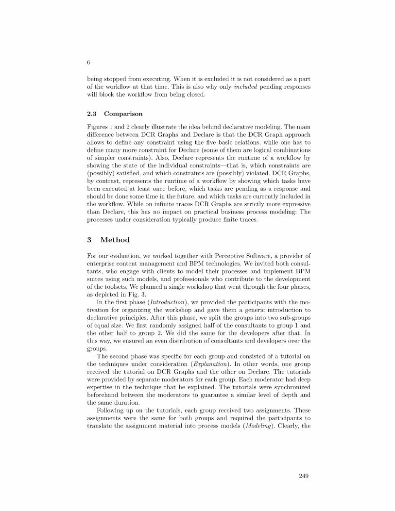
6
being stopped from executing. When it is excluded it is not considered as a partof the workflow at that time. This is also why only included pending responseswill block the workflow from being closed.
2.3 Comparison
Figures 1 and 2 clearly illustrate the idea behind declarative modeling. The maindifference between DCR Graphs and Declare is that the DCR Graph approachallows to define any constraint using the five basic relations, while one has todefine many more constraint for Declare (some of them are logical combinationsof simpler constraints). Also, Declare represents the runtime of a workflow byshowing the state of the individual constraints—that is, which constraints are(possibly) satisfied, and which constraints are (possibly) violated. DCR Graphs,by contrast, represents the runtime of a workflow by showing which tasks havebeen executed at least once before, which tasks are pending as a response andshould be done some time in the future, and which tasks are currently included inthe workflow. While on infinite traces DCR Graphs are strictly more expressivethan Declare, this has no impact on practical business process modeling: Theprocesses under consideration typically produce finite traces.
3 Method
For our evaluation, we worked together with Perceptive Software, a provider ofenterprise content management and BPM technologies. We invited both consul-tants, who engage with clients to model their processes and implement BPMsuites using such models, and professionals who contribute to the developmentof the toolsets. We planned a single workshop that went through the four phases,as depicted in Fig. 3.
In the first phase (Introduction), we provided the participants with the mo-tivation for organizing the workshop and gave them a generic introduction todeclarative principles. After this phase, we split the groups into two sub-groupsof equal size. We first randomly assigned half of the consultants to group 1 andthe other half to group 2. We did the same for the developers after that. Inthis way, we ensured an even distribution of consultants and developers over thegroups.
The second phase was specific for each group and consisted of a tutorial onthe techniques under consideration (Explanation). In other words, one groupreceived the tutorial on DCR Graphs and the other on Declare. The tutorialswere provided by separate moderators for each group. Each moderator had deepexpertise in the technique that he explained. The tutorials were synchronizedbeforehand between the moderators to guarantee a similar level of depth andthe same duration.
Following up on the tutorials, each group received two assignments. Theseassignments were the same for both groups and required the participants totranslate the assignment material into process models (Modeling). Clearly, the
249
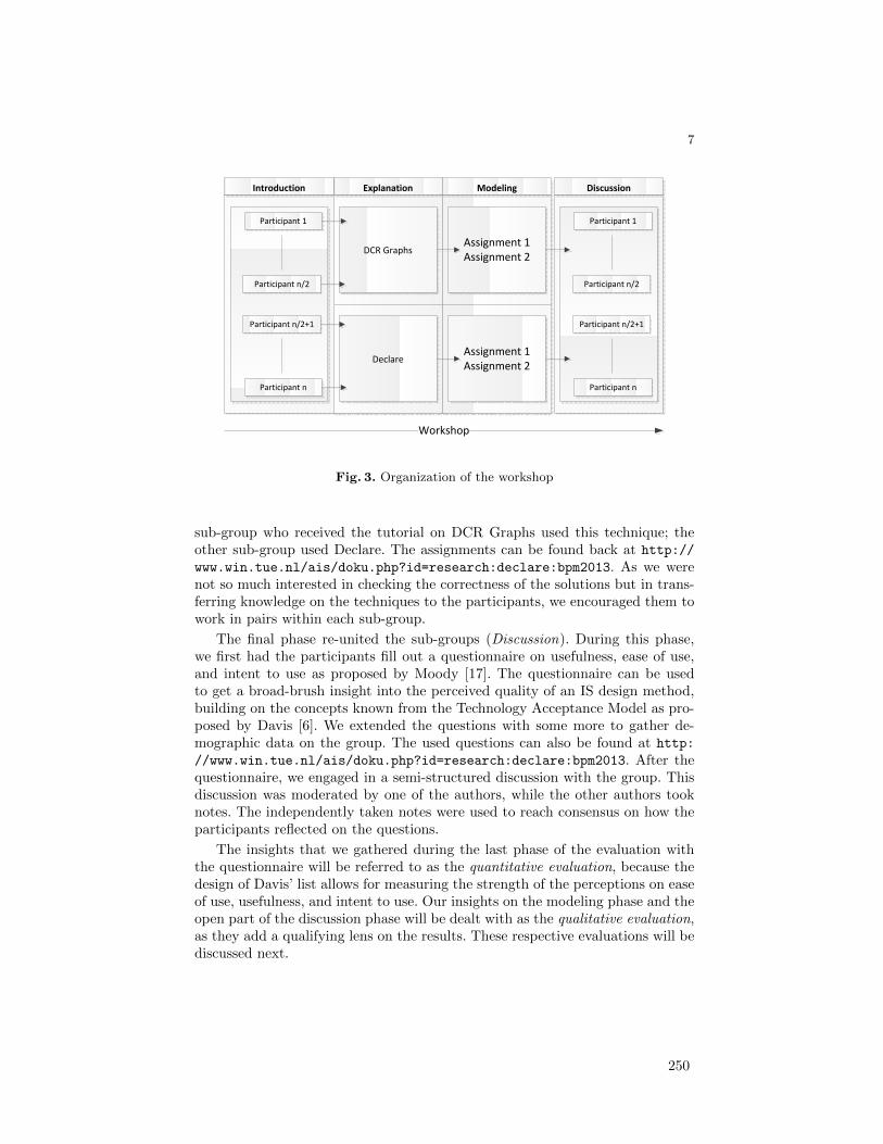
7
Explanation ModelingIntroduction
DCR Graphs
Declare
Assignment 1Assignment 2
Participant 1
Participant n
Assignment 1Assignment 2
Participant n/2
Participant n/2+1
Discussion
Participant 1
Participant n
Participant n/2
Participant n/2+1
Workshop
Fig. 3. Organization of the workshop
sub-group who received the tutorial on DCR Graphs used this technique; theother sub-group used Declare. The assignments can be found back at http://
www.win.tue.nl/ais/doku.php?id=research:declare:bpm2013. As we werenot so much interested in checking the correctness of the solutions but in trans-ferring knowledge on the techniques to the participants, we encouraged them towork in pairs within each sub-group.
The final phase re-united the sub-groups (Discussion). During this phase,we first had the participants fill out a questionnaire on usefulness, ease of use,and intent to use as proposed by Moody [17]. The questionnaire can be usedto get a broad-brush insight into the perceived quality of an IS design method,building on the concepts known from the Technology Acceptance Model as pro-posed by Davis [6]. We extended the questions with some more to gather de-mographic data on the group. The used questions can also be found at http:
//www.win.tue.nl/ais/doku.php?id=research:declare:bpm2013. After thequestionnaire, we engaged in a semi-structured discussion with the group. Thisdiscussion was moderated by one of the authors, while the other authors tooknotes. The independently taken notes were used to reach consensus on how theparticipants reflected on the questions.
The insights that we gathered during the last phase of the evaluation withthe questionnaire will be referred to as the quantitative evaluation, because thedesign of Davis’ list allows for measuring the strength of the perceptions on easeof use, usefulness, and intent to use. Our insights on the modeling phase and theopen part of the discussion phase will be dealt with as the qualitative evaluation,as they add a qualifying lens on the results. These respective evaluations will bediscussed next.
250
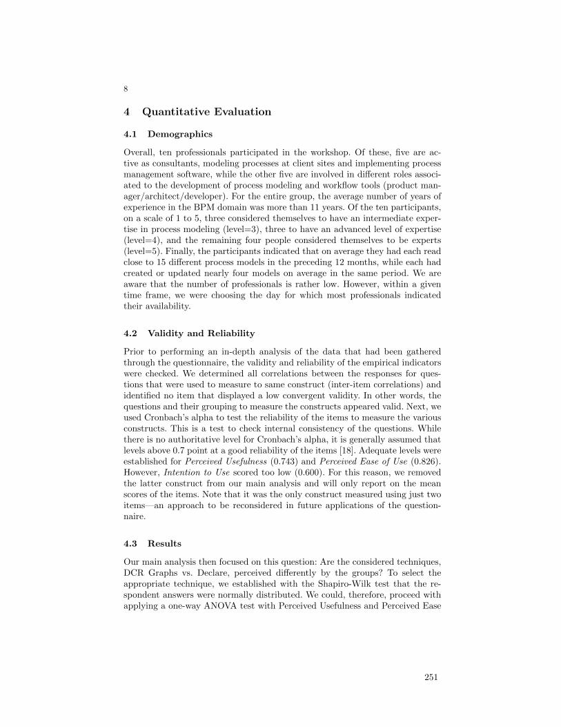
8
4 Quantitative Evaluation
4.1 Demographics
Overall, ten professionals participated in the workshop. Of these, five are ac-tive as consultants, modeling processes at client sites and implementing processmanagement software, while the other five are involved in different roles associ-ated to the development of process modeling and workflow tools (product man-ager/architect/developer). For the entire group, the average number of years ofexperience in the BPM domain was more than 11 years. Of the ten participants,on a scale of 1 to 5, three considered themselves to have an intermediate exper-tise in process modeling (level=3), three to have an advanced level of expertise(level=4), and the remaining four people considered themselves to be experts(level=5). Finally, the participants indicated that on average they had each readclose to 15 different process models in the preceding 12 months, while each hadcreated or updated nearly four models on average in the same period. We areaware that the number of professionals is rather low. However, within a giventime frame, we were choosing the day for which most professionals indicatedtheir availability.
4.2 Validity and Reliability
Prior to performing an in-depth analysis of the data that had been gatheredthrough the questionnaire, the validity and reliability of the empirical indicatorswere checked. We determined all correlations between the responses for ques-tions that were used to measure to same construct (inter-item correlations) andidentified no item that displayed a low convergent validity. In other words, thequestions and their grouping to measure the constructs appeared valid. Next, weused Cronbach’s alpha to test the reliability of the items to measure the variousconstructs. This is a test to check internal consistency of the questions. Whilethere is no authoritative level for Cronbach’s alpha, it is generally assumed thatlevels above 0.7 point at a good reliability of the items [18]. Adequate levels wereestablished for Perceived Usefulness (0.743) and Perceived Ease of Use (0.826).However, Intention to Use scored too low (0.600). For this reason, we removedthe latter construct from our main analysis and will only report on the meanscores of the items. Note that it was the only construct measured using just twoitems—an approach to be reconsidered in future applications of the question-naire.
4.3 Results
Our main analysis then focused on this question: Are the considered techniques,DCR Graphs vs. Declare, perceived differently by the groups? To select theappropriate technique, we established with the Shapiro-Wilk test that the re-spondent answers were normally distributed. We could, therefore, proceed withapplying a one-way ANOVA test with Perceived Usefulness and Perceived Ease
251
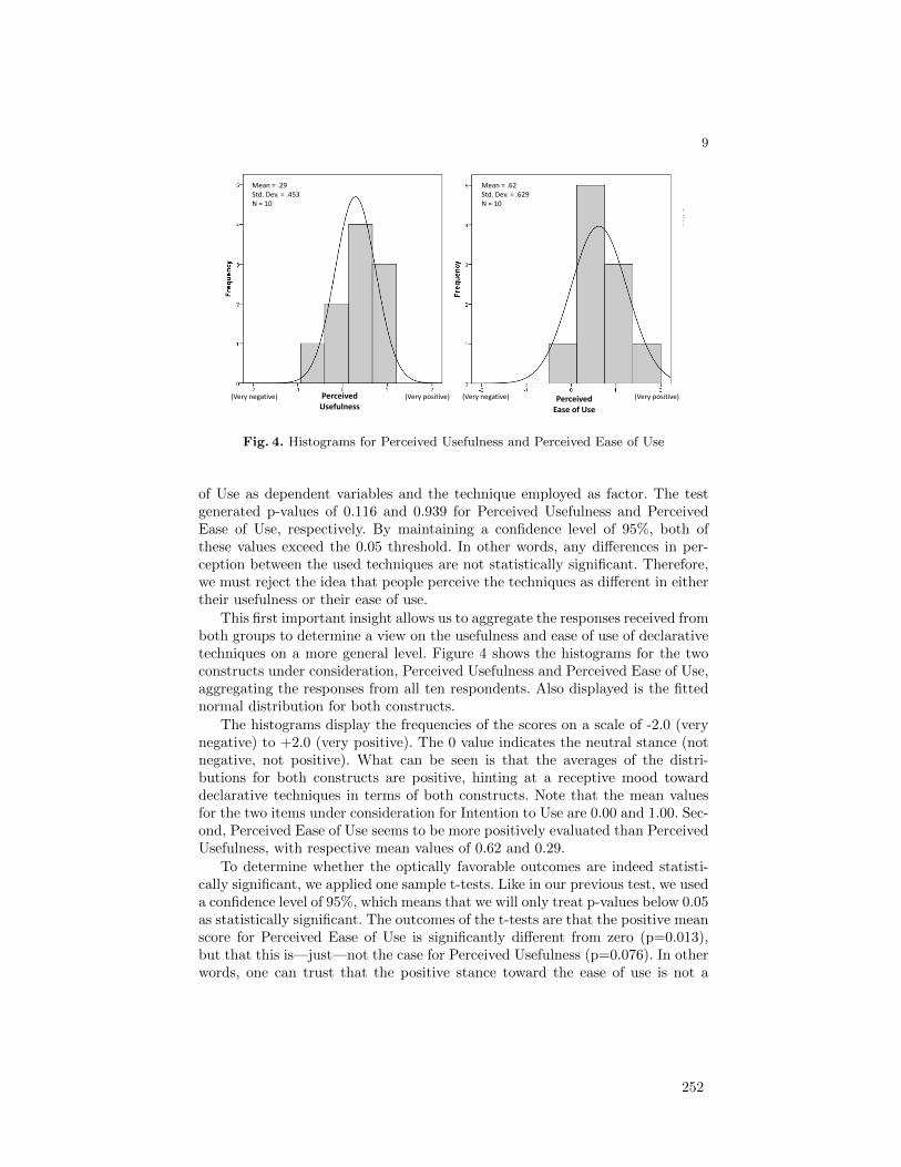
9
Perceived Usefulness
Mean = .29 Std. Dev. = .453 N = 10
Perceived Ease of Use
Mean = .62 Std. Dev. = .629 N = 10
(Very negative) (Very negative) (Very positive) (Very positive)
Fig. 4. Histograms for Perceived Usefulness and Perceived Ease of Use
of Use as dependent variables and the technique employed as factor. The testgenerated p-values of 0.116 and 0.939 for Perceived Usefulness and PerceivedEase of Use, respectively. By maintaining a confidence level of 95%, both ofthese values exceed the 0.05 threshold. In other words, any differences in per-ception between the used techniques are not statistically significant. Therefore,we must reject the idea that people perceive the techniques as different in eithertheir usefulness or their ease of use.
This first important insight allows us to aggregate the responses received fromboth groups to determine a view on the usefulness and ease of use of declarativetechniques on a more general level. Figure 4 shows the histograms for the twoconstructs under consideration, Perceived Usefulness and Perceived Ease of Use,aggregating the responses from all ten respondents. Also displayed is the fittednormal distribution for both constructs.
The histograms display the frequencies of the scores on a scale of -2.0 (verynegative) to +2.0 (very positive). The 0 value indicates the neutral stance (notnegative, not positive). What can be seen is that the averages of the distri-butions for both constructs are positive, hinting at a receptive mood towarddeclarative techniques in terms of both constructs. Note that the mean valuesfor the two items under consideration for Intention to Use are 0.00 and 1.00. Sec-ond, Perceived Ease of Use seems to be more positively evaluated than PerceivedUsefulness, with respective mean values of 0.62 and 0.29.
To determine whether the optically favorable outcomes are indeed statisti-cally significant, we applied one sample t-tests. Like in our previous test, we useda confidence level of 95%, which means that we will only treat p-values below 0.05as statistically significant. The outcomes of the t-tests are that the positive meanscore for Perceived Ease of Use is significantly different from zero (p=0.013),but that this is—just—not the case for Perceived Usefulness (p=0.076). In otherwords, one can trust that the positive stance toward the ease of use is not a
252
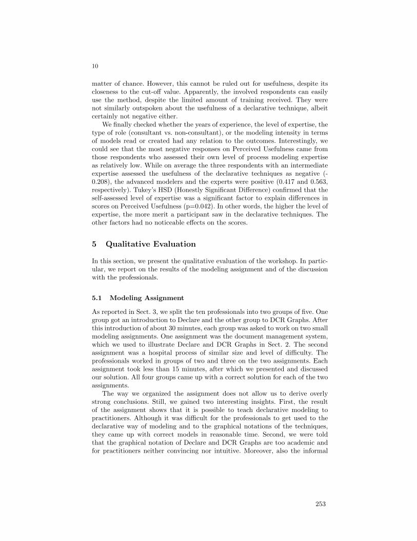
10
matter of chance. However, this cannot be ruled out for usefulness, despite itscloseness to the cut-off value. Apparently, the involved respondents can easilyuse the method, despite the limited amount of training received. They werenot similarly outspoken about the usefulness of a declarative technique, albeitcertainly not negative either.
We finally checked whether the years of experience, the level of expertise, thetype of role (consultant vs. non-consultant), or the modeling intensity in termsof models read or created had any relation to the outcomes. Interestingly, wecould see that the most negative responses on Perceived Usefulness came fromthose respondents who assessed their own level of process modeling expertiseas relatively low. While on average the three respondents with an intermediateexpertise assessed the usefulness of the declarative techniques as negative (-0.208), the advanced modelers and the experts were positive (0.417 and 0.563,respectively). Tukey’s HSD (Honestly Significant Difference) confirmed that theself-assessed level of expertise was a significant factor to explain differences inscores on Perceived Usefulness (p=0.042). In other words, the higher the level ofexpertise, the more merit a participant saw in the declarative techniques. Theother factors had no noticeable effects on the scores.
5 Qualitative Evaluation
In this section, we present the qualitative evaluation of the workshop. In partic-ular, we report on the results of the modeling assignment and of the discussionwith the professionals.
5.1 Modeling Assignment
As reported in Sect. 3, we split the ten professionals into two groups of five. Onegroup got an introduction to Declare and the other group to DCR Graphs. Afterthis introduction of about 30 minutes, each group was asked to work on two smallmodeling assignments. One assignment was the document management system,which we used to illustrate Declare and DCR Graphs in Sect. 2. The secondassignment was a hospital process of similar size and level of difficulty. Theprofessionals worked in groups of two and three on the two assignments. Eachassignment took less than 15 minutes, after which we presented and discussedour solution. All four groups came up with a correct solution for each of the twoassignments.
The way we organized the assignment does not allow us to derive overlystrong conclusions. Still, we gained two interesting insights. First, the resultof the assignment shows that it is possible to teach declarative modeling topractitioners. Although it was difficult for the professionals to get used to thedeclarative way of modeling and to the graphical notations of the techniques,they came up with correct models in reasonable time. Second, we were toldthat the graphical notation of Declare and DCR Graphs are too academic andfor practitioners neither convincing nor intuitive. Moreover, also the informal
253
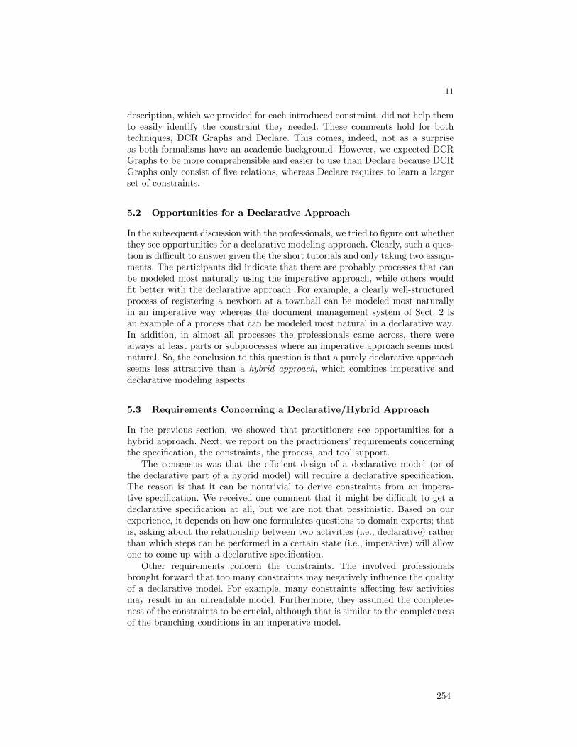
11
description, which we provided for each introduced constraint, did not help themto easily identify the constraint they needed. These comments hold for bothtechniques, DCR Graphs and Declare. This comes, indeed, not as a surpriseas both formalisms have an academic background. However, we expected DCRGraphs to be more comprehensible and easier to use than Declare because DCRGraphs only consist of five relations, whereas Declare requires to learn a largerset of constraints.
5.2 Opportunities for a Declarative Approach
In the subsequent discussion with the professionals, we tried to figure out whetherthey see opportunities for a declarative modeling approach. Clearly, such a ques-tion is difficult to answer given the the short tutorials and only taking two assign-ments. The participants did indicate that there are probably processes that canbe modeled most naturally using the imperative approach, while others wouldfit better with the declarative approach. For example, a clearly well-structuredprocess of registering a newborn at a townhall can be modeled most naturallyin an imperative way whereas the document management system of Sect. 2 isan example of a process that can be modeled most natural in a declarative way.In addition, in almost all processes the professionals came across, there werealways at least parts or subprocesses where an imperative approach seems mostnatural. So, the conclusion to this question is that a purely declarative approachseems less attractive than a hybrid approach, which combines imperative anddeclarative modeling aspects.
5.3 Requirements Concerning a Declarative/Hybrid Approach
In the previous section, we showed that practitioners see opportunities for ahybrid approach. Next, we report on the practitioners’ requirements concerningthe specification, the constraints, the process, and tool support.
The consensus was that the efficient design of a declarative model (or ofthe declarative part of a hybrid model) will require a declarative specification.The reason is that it can be nontrivial to derive constraints from an impera-tive specification. We received one comment that it might be difficult to get adeclarative specification at all, but we are not that pessimistic. Based on ourexperience, it depends on how one formulates questions to domain experts; thatis, asking about the relationship between two activities (i.e., declarative) ratherthan which steps can be performed in a certain state (i.e., imperative) will allowone to come up with a declarative specification.
Other requirements concern the constraints. The involved professionalsbrought forward that too many constraints may negatively influence the qualityof a declarative model. For example, many constraints affecting few activitiesmay result in an unreadable model. Furthermore, they assumed the complete-ness of the constraints to be crucial, although that is similar to the completenessof the branching conditions in an imperative model.
254
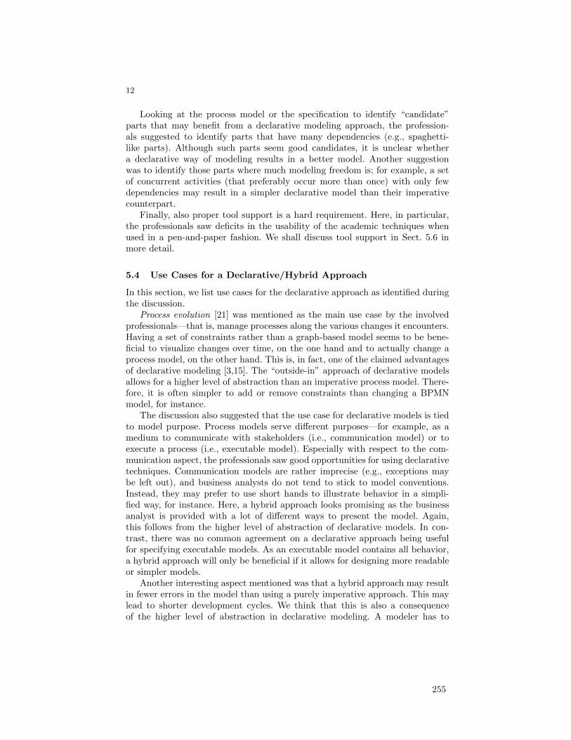
12
Looking at the process model or the specification to identify “candidate”parts that may benefit from a declarative modeling approach, the profession-als suggested to identify parts that have many dependencies (e.g., spaghetti-like parts). Although such parts seem good candidates, it is unclear whethera declarative way of modeling results in a better model. Another suggestionwas to identify those parts where much modeling freedom is; for example, a setof concurrent activities (that preferably occur more than once) with only fewdependencies may result in a simpler declarative model than their imperativecounterpart.
Finally, also proper tool support is a hard requirement. Here, in particular,the professionals saw deficits in the usability of the academic techniques whenused in a pen-and-paper fashion. We shall discuss tool support in Sect. 5.6 inmore detail.
5.4 Use Cases for a Declarative/Hybrid Approach
In this section, we list use cases for the declarative approach as identified duringthe discussion.
Process evolution [21] was mentioned as the main use case by the involvedprofessionals—that is, manage processes along the various changes it encounters.Having a set of constraints rather than a graph-based model seems to be bene-ficial to visualize changes over time, on the one hand and to actually change aprocess model, on the other hand. This is, in fact, one of the claimed advantagesof declarative modeling [3,15]. The “outside-in” approach of declarative modelsallows for a higher level of abstraction than an imperative process model. There-fore, it is often simpler to add or remove constraints than changing a BPMNmodel, for instance.
The discussion also suggested that the use case for declarative models is tiedto model purpose. Process models serve different purposes—for example, as amedium to communicate with stakeholders (i.e., communication model) or toexecute a process (i.e., executable model). Especially with respect to the com-munication aspect, the professionals saw good opportunities for using declarativetechniques. Communication models are rather imprecise (e.g., exceptions maybe left out), and business analysts do not tend to stick to model conventions.Instead, they may prefer to use short hands to illustrate behavior in a simpli-fied way, for instance. Here, a hybrid approach looks promising as the businessanalyst is provided with a lot of different ways to present the model. Again,this follows from the higher level of abstraction of declarative models. In con-trast, there was no common agreement on a declarative approach being usefulfor specifying executable models. As an executable model contains all behavior,a hybrid approach will only be beneficial if it allows for designing more readableor simpler models.
Another interesting aspect mentioned was that a hybrid approach may resultin fewer errors in the model than using a purely imperative approach. This maylead to shorter development cycles. We think that this is also a consequenceof the higher level of abstraction in declarative modeling. A modeler has to
255

13
identify the constraints rather than encode it in terms of control flow. However,no experience report or empirical results exist that confirm this assumption.
5.5 Limitations of a Declarative/Hybrid Approach
In this section, we report on limitations of a declarative/hybrid approach con-cerning the specification, the modeling paradigm, and the usability.
The main concern regarding the specification is that currently all specifica-tions are imperative (e.g., “we first do this, then that”), and it seems to be verydifficult to produce a declarative model for such a specification. As discussed inSect. 5.3, we think that it is possible to receive declarative specifications.
There has been a paradigm shift in system development from monolithicsystems to component-based systems that are distributed within and across or-ganizational boundaries. One prominent computing paradigm that implementsthis trend is service-oriented computing (SOC) [19]. We received concerns thatin this setting declarative modeling techniques may be less applicable comparedto imperative techniques. The reason for this concern lies in the fact that cer-tain constraints affect activities of an individual component, whereas other con-straints affect activities of different components. Declarative techniques have,however, been successfully applied in the service-oriented setting [14,15], andit has been studied how a declarative cross-organizational workflow containingglobal constraints can be projected to its individual localized components [11],so we are convinced that this concern is unsubstantiated.
Another limitation concerns the usability of existing techniques and tools.Current tool support is mainly academic by nature and seems, therefore, notoverly concerned with usability issues. Moreover, the declarative paradigm alsorequires a different way of thinking, making it perhaps difficult for practition-ers to understand declarative models. Here, more research is required to makedeclarative techniques more comprehensible.
5.6 Requirements Concerning Tool Support
In this section, we report on feedback we received concerning Declare and DCRGraphs and general requirements concerning tool support.
Several requirements on tools that were discussed deal with the specificationand visualization of constraints. As mentioned earlier in Sect. 5.1, the profes-sionals mentioned that working with constraints was relatively difficult for them.The graphical notations used in Declare and DCR Graphs were not always thatintuitive. Moreover, specifying constraints in plain English is not always help-ful either, because it is often nontrivial to identify the differences between twoconstraints. Therefore, the professionals proposed that constraints should be au-tomatically derived from an informal textual specification. This problem hasindeed been investigated in the field of computer-aided verification, for instance.Different approaches have been proposed, for example [7,5], but none of themcould solve the problem entirely.
256
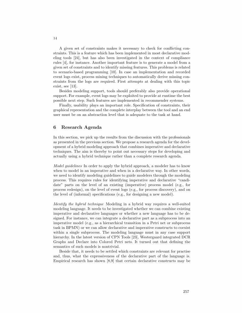
14
A given set of constraints makes it necessary to check for conflicting con-straints. This is a feature which has been implemented in most declarative mod-eling tools [24], but has also been investigated in the context of compliancerules [4], for instance. Another important feature is to generate a model from agiven set of constraints and to identify missing features. This problems is relatedto scenario-based programming [10]. In case an implementation and recordedevent logs exist, process mining techniques to automatically derive missing con-straints from the logs are required. First attempts at dealing with this topicexist, see [13].
Besides modeling support, tools should preferably also provide operationalsupport. For example, event logs may be exploited to provide at runtime the bestpossible next step. Such features are implemented in recommender systems.
Finally, usability plays an important role. Specification of constraints, theirgraphical representation and the complete interplay between the tool and an enduser must be on an abstraction level that is adequate to the task at hand.
6 Research Agenda
In this section, we pick up the results from the discussion with the professionalsas presented in the previous section. We propose a research agenda for the devel-opment of a hybrid modeling approach that combines imperative and declarativetechniques. The aim is thereby to point out necessary steps for developing andactually using a hybrid technique rather than a complete research agenda.
Model guidelines In order to apply the hybrid approach, a modeler has to knowwhen to model in an imperative and when in a declarative way. In other words,we need to identify modeling guidelines to guide modelers through the modelingprocess. This requires rules for identifying imperative and declarative “candi-date” parts on the level of an existing (imperative) process model (e.g., forprocess redesign), on the level of event logs (e.g., for process discovery), and onthe level of (informal) specifications (e.g., for designing a new model).
Identify the hybrid technique Modeling in a hybrid way requires a well-suitedmodeling language. It needs to be investigated whether we can combine existingimperative and declarative languages or whether a new language has to be de-signed. For instance, we can integrate a declarative part as a subprocess into animperative model (e.g., as a hierarchical transition in a Petri net or subprocesstask in BPMN) or we can allow declarative and imperative constructs to coexistwithin a single subprocess. The modeling language must in any case supporthierarchy. In the latest version of CPN Tools [23], Westergaard integrated DCRGraphs and Declare into Colored Petri nets. It turned out that defining thesemantics of such models is nontrivial.
Beside that, it needs to be settled which constraints are relevant for practiseand, thus, what the expressiveness of the declarative part of the language is.Empirical research has shown [8,9] that certain declarative constructs may be
257

15
more difficult to understand. Thus, we think the language should not containtoo many declarative constructs, but this needs further empirical investigation.
Also, the graphical representation of hybrid models must be investigated. Dif-ferent graphical notations exist, for example, compare DCR Graphs and Declare.Insights from [16] may aid the design of a hybrid notation.
Analysis of hybrid models The novel modeling approach needs analysis tech-niques including the verification of models, performance analysis, and property-preserving abstraction and refinement techniques. Also, process mining tech-niques [1] are needed—for example, checking the conformance of an event logand a hybrid model and discovering a hybrid model from a given event log.
Tool support To show the applicability of the hybrid modeling technique, toolsupport is a sine qua no. As reported in Sect. 5.6, research has to be performedto simplify the use of declarative techniques, for example, finding a way to deriveconstraints from informal specifications that can be used by business analystswithout requiring knowledge about temporal logics.
7 Conclusion
We reported on a workshop on declarative modeling given to professionals fromindustry. The goal of this workshop was to gain insight into what practitionersthink about declarative modeling and what opportunities they see to use thistechnique. Our quantitative evaluation showed that they were mostly positiveand open to this modeling paradigm. In particular, the techniques were rathereasy to learn. The qualitative evaluation showed that the practitioners did singleout the use of declarative techniques in the context of a hybrid approach, whichcombines imperative and declarative modeling. Although our study is only basedon a small group of practitioners, we are convinced that practise can benefit fromsuch a hybrid modeling approach. To arrive at such an approach, we proposeda research agenda for the development of a hybrid approach.
In our ongoing research, we plan to work on the development of model-ing guidelines. We will investigate techniques to identify “candidate” parts ofa model for which a declarative way of modeling seems most natural. Also, weplan to study event logs and process models and try to use the results to iden-tify constraints that frequently occur. In a second branch of research, we willinvestigate what a hybrid technique may look like, thereby using Declare, DCRGraphs and CPN Tools as starting points for our studies.
References
1. Aalst, W.M.P.v.d.: Process Mining: Discovery, Conformance and Enhancement ofBusiness Processes. Springer (2011)
2. Aalst, W.M.P.v.d.: Business process management: A comprehensive survey. ISRNSoftware Engineering 2013 (2013)
258

16
3. Aalst, W.M.P.v.d., Pesic, M., Schonenberg, H.: Declarative workflows: Balancingbetween flexibility and support. Computer Science - R&D 23(2), 99–113 (2009)
4. Awad, A., Weidlich, M., Weske, M.: Consistency checking of compliance rules. In:BIS 2010. LNBIP, vol. 47, pp. 106–118 (2010)
5. Cobleigh, R.L., Avrunin, G.S., Clarke, L.A.: User guidance for creating precise andaccessible property specifications. In: SIGSOFT FSE. pp. 208–218. ACM (2006)
6. Davis, F.D.: Perceived usefulness, perceived ease of use, and user acceptance ofinformation technology. MIS Q. 13(3), 319–340 (1989)
7. Dwyer, M.B., Avrunin, G.S., Corbett, J.C.: Patterns in property specifications forfinite-state verification. In: ICSE 1999. pp. 411–420. ACM (1999)
8. Fahland, D., Lubke, D., Mendling, J., Reijers, H.A., Weber, B., Weidlich, M.,Zugal, S.: Declarative versus imperative process modeling languages: The issue ofunderstandability. In: BMMDS. LNBIP, vol. 29, pp. 353–366. Springer (2009)
9. Fahland, D., Mendling, J., Reijers, H.A., Weber, B., Weidlich, M., Zugal, S.: Declar-ative versus imperative process modeling languages: The issue of maintainability.In: BPM Workshops. LNBIP, vol. 43, pp. 477–488. Springer (2010)
10. Harel, D.: Come, let’s play - scenario-based programming using LSCs and theplay-engine. Springer (2003)
11. Hildebrandt, T., Mukkamala, R.R., Slaats, T.: Safe distribution of declarative pro-cesses. In: SEFM 2011. pp. 237–252. Springer (2011)
12. Hildebrandt, T.T., Mukkamala, R.R.: Declarative event-based workflow as dis-tributed dynamic condition response graphs. In: PLACES 2010. EPTCS, vol. 69,pp. 59–73 (2010)
13. Maggi, F.M., Bose, R.P.J.C., Aalst, W.M.P.v.d.: Efficient discovery of understand-able declarative process models from event logs. In: CAiSE 2012. LNCS, vol. 7328,pp. 270–285. Springer (2012)
14. Montali, M.: Specification and Verification of Declarative Open Interaction Models- A Logic-Based Approach, LNBIP, vol. 56. Springer (2010)
15. Montali, M., Pesic, M., Aalst, W.M.P.v.d., Chesani, F., Mello, P., Storari, S.:Declarative specification and verification of service choreographiess. TWEB 4(1)(2010)
16. Moody, D.: The physics of notations: toward a scientific basis for constructingvisual notations in software engineering. Software Engineering, IEEE Transactionson 35(6), 756–779 (2009)
17. Moody, D.L.: The method evaluation model: a theoretical model for validatinginformation systems design methods. In: ECIS 2003. pp. 1327–1336 (2003)
18. Nunnally, J.: C.(1978). Psychometric theory. New York: McGraw-Hill (1978)19. Papazoglou, M.P.: Web Services - Principles and Technology. Prentice Hall (2008)20. Pichler, P., Weber, B., Zugal, S., Pinggera, J., Mendling, J., Reijers, H.A.: Impera-
tive versus declarative process modeling languages: An empirical investigation. In:BPM Workshops 2011, Part I. LNBIP, vol. 99, pp. 383–394. Springer (2012)
21. Reichert, M., Weber, B.: Enabling Flexibility in Process-Aware Information Sys-tems. Springer (2012)
22. Weber, B., Reijers, H.A., Zugal, S., Wild, W.: The declarative approach to businessprocess execution: An empirical test. In: CAiSE 2009. LNCS, vol. 5565, pp. 470–485. Springer (2009)
23. Westergaard, M.: CPN Tools 4: Multi-formalism and extensibility. In: Petri Nets2013. LNCS, Springer (2013), accepted for publication
24. Westergaard, M., Maggi, F.M.: Declare: A tool suite for declarative workflow mod-eling and enactment. In: BPM (Demos) 2011. CEUR Workshop Proceedings, vol.820. CEUR-WS.org (2011)
259

Mixing Paradigms
for More Comprehensible Models
Michael Westergaard1,2? and Tijs Slaats3,4
1 Department of Mathematics and Computer Science,Eindhoven University of Technology, The Netherlands
2 National Research University Higher School of Economics,Moscow, 101000, Russia
3 IT University of CopenhagenRued Langgaardsvej 7, 2300 Copenhagen, Denmark
4 Exformatics A/S, Lautrupsgade 13, 2100 Copenhagen, [email protected], [email protected]
Abstract. Petri nets e�ciently model both data- and control-�ow.Control-�ow is either modeled explicitly as �ow of a speci�c kind of data,or implicit based on the data-�ow. Explicit modeling of control-�ow isuseful for well-known and highly structured processes, but may makemodeling of abstract features of models, or processes which are highlydynamic, overly complex. Declarative modeling, such as is supported byDeclare and DCR graphs, focus on control-�ow, but does not specify itexplicitly; instead speci�cations come in the form of constraints on theorder or appearance of tasks. In this paper we propose a combination ofthe two, using colored Petri nets instead of plain Petri nets to providefull data support. The combined approach makes it possible to add afocus on data to declarative languages, and to remove focus from theexplicit control-�ow from Petri nets for dynamic or abstract processes.In addition to enriching both procedural processes in the form of Petrinets and declarative processes, we also support a �ow from modelingonly abstract data- and control-�ow of a model towards a more explicitcontrol-�ow model if so desired. We de�ne our combined approach, andprovide considerations necessary for enactment. Our approach has beenimplemented in CPN Tools 4.
1 Introduction
Petri nets provide a powerful formalism for specifying many real-life systems,including business processes. Petri nets excel by having a duality between dataand events, yielding a very powerful tool for specifying how data �ows though asystem. Control-�ow of a Petri net model is often modeled explicitly as �ow of aspeci�c kind of data, similar to a program counter in traditional programming.Alternatively, the control-�ow is not modeled at all, and just manifests as a con-sequence of the data-�ow. As such, we call a Petri net model a procedural model
? Support from the Basic Research Program of the National Research UniversityHigher School of Economics is gratefully acknowledged.
260
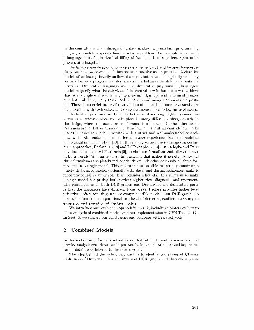
as the control-�ow when disregarding data is close to procedural programminglanguages: modelers specify how to solve a problem. An example where sucha language is useful, is classical �lling of forms, such as a patient registrationprocess at a hospital.
Declarative speci�cation of processes is an emerging trend for specifying espe-cially business processes, but it has not seen massive use in practice. Declarativemodels often focus primarily on �ow of control, but instead of explicitly modelingcontrol-�ow as a program counter, constraints between the di�erent events aredescribed. Declarative languages resemble declarative programming languages:modelers specify what the intention of the control-�ow is, but not how to achievethat. An example where such languages are useful, is a patient treatment processat a hospital; here, many tests need to be run and many treatments are possi-ble. There is no strict order of tests and treatments, but some treatments areincompatible with each other, and some treatments need follow-up treatments.
Declarative processes are typically better at describing highly dynamic en-vironments, where actions can take place in many di�erent orders, or early inthe design, where the exact order of events is unknown. On the other hand,Petri nets are far better at modeling data-�ow, and the strict control-�ow modelmakes it easier to model processes with a strict and well-understood control-�ow, which also makes it much easier to extract experiences from the model toan eventual implementation [10]. In this paper, we propose to merge two declar-ative approaches, Declare [15,19] and DCR graphs [7,13], with a high-level Petrinets formalism, colored Petri nets [9], to obtain a formalism that o�ers the bestof both worlds. We aim to do so in a manner that makes it possible to use allthree formalisms completely independently of each other or to mix all three for-malisms in a single model. This makes it also possible to initially construct apurely declarative model, optionally with data, and during re�nement make itmore procedural as applicable. If we consider a hospital, this allows us to makea single model comprising both patient registration, diagnosis, and treatment.The reason for using both DCR graphs and Declare for the declarative partsis that the languages have di�erent focus areas: Declare provides higher levelprimitives, often resulting in more comprehensible models, but DCR graphs donot su�er from the computational overhead of detecting con�icts necessary toensure correct execution of Declare models.
We introduce our combined approach in Sect. 2, including pointers on how toallow analysis of combined models and our implementation in CPN Tools 4 [17].In Sect. 3, we sum up our conclusions and compare with related work.
2 Combined Models
In this section we informally introduce our hybrid model and its semantics, andprovide analysis considerations important for implementation. Actual implemen-tation details are deferred to the next section.
The idea behind the hybrid approach is to identify transitions of CP-netswith tasks of Declare models and events of DCR graphs and then allow places
261
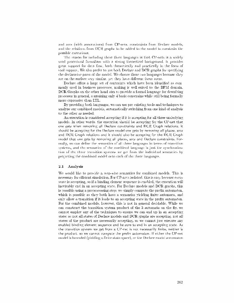
and arcs (with annotations) from CP-nets, constraints from Declare models,and the relations from DCR graphs to be added to the model to constrain thepossible executions.
The reason for including these three languages is that CP-nets is a widelyused procedural formalism with a strong theoretical background. It providesgreat support for data �ow, both theoretically and practically in the form oftool support. We also prefer to use both Declare and DCR graphs for specifyingthe declarative parts of the model. We choose these two languages because theyare on the surface very similar, yet they have di�erent focus areas.
Declare o�ers a large set of contraints which have been identi�ed as com-monly used in business processes, making it well-suited to the BPM domain.DCR Graphs on the other hand aim to provide a formal language for describingprocesses in general, containing only 4 basic constrains while still being formallymore expressive than LTL.
By providing both languages, we can use pre-existing tools and techniques toanalyze our combined models, automatically switching from one kind of analysisto the other as needed.
An execution is considered accepting if it is accepting for all three underlyingmodels. In other words, the execution should be accepting for the CP-net thatone gets when removing all Declare constraints and DCR Graph relations, itshould be accepting for the Declare model one gets by removing all places, arcsand DCR Graph relations and it should also be accepting for the DCR Graphmodel that one gets by removing all places, arcs and Declare constraints. For-mally, we can de�ne the semantics of all three languages in terms of transitionsystems, and the semantics of the combined language is just the synchroniza-tion of the three transition systems we get from the individual semantics byprojecting the combined model onto each of the three languages.
2.1 Analysis
We would like to provide a step-wise semantics for combined models. This isnecessary for e�cient simulation. For CP-nets isolated, this is easy because everystate is accepting, so if a binding element sequence is enabled, the execution willinevitably end in an accepting state. For Declare models and DCR graphs, thisis possible using a preprocessing step: we simply compute the pre�x automaton,which is possible as they both have a semantics yielding �nite automata, andonly allow a transition if it leads to an accepting state in the pre�x automaton.For the combined models, however, this is not in general decidable. While wecan construct the transition system product of the 3 automata on the �y, wecannot employ any of the techniques to ensure we can end up in an acceptingstate: as not all states of Declare models and DCR graphs are accepting, not allstates of the product are necessarily accepting, so we cannot just execute anyenabled binding element sequence and be sure to end in an accepting state. Asthe transition system we get from a CP-net is not necessarily �nite, neither isthe product, so we cannot compute the pre�x automaton. If either the CP-netmodel is bounded (yielding a �nite state space), or the Declare model automaton
262

and the DCR graph automaton only have accepting states, we can use the factthat these properties are preserved by transition system product and use theappropriate technique. Otherwise, we must settle for weaker guarantees.
When talking about runtime veri�cation of Declare models [12], each con-straint can be in not just the two states satis�ed and violated , but also in twoweaker states, where a constraint is only temporarily satis�ed or violated, butfuture execution may violate or satisfy it. Only when the execution is termi-nated, is it possible to collapse possible satis�ed/violated constraints into their(permanently) satis�ed/violated counterparts.
For DCR Graphs we do not keep track of the state of individual constraints,instead we have a current marking and on execution check that the executedevent is enabled and calculate the new marking. If a marking contains no pendingincluded responses, the DCR Graph is in an accepting state and the process canterminate. Feedback to the user consists of showing which events have occuredbefore, are enabled and need to occcur.
Simple simulation. As demonstrated in [18], even if Declare is decidable,constructing the automaton for the full system can be very time and memoryconsuming � it is exponential in the number of constraints. To avoid this over-head, we can instead create an automaton for each individual constraint. If wedo so, we can avoid ever violating individual constraints, while retaining fastsimulation (we can update the model in the initial state in constant time). CPNTools o�ers a mixed mode, where simulation and editing are interleaved. Thisis useful for testing and debugging, but requires that the simulation can resumevery quickly, so performing an operation that is exponential in the size of themodel may be undesirable (at least for large models). By constructing the indi-vidual automata, we can avoid ever (permanently) violating constraints, and forsome constraints, e.g., init, this is su�cient. For other constraints, this provides abest-e�ort but fast simulation mode (we can update the model in constant timein the initial state). We call this the simple simulation approach. The simplesimulation approach for DCR Graphs comes down to doing basic runtime veri�-cation as described previously: checking that an event is enabled in the currentmarking and calculating a new marking can be done in constant time.
Smart simulation. As shown in [11] some Declare constraints can be in acon�icted state: they are not violated, but also cannot all be (possibly) satis�edat the same time. We can only catch this if we construct the automaton for thefull Declare model. By making the product explicit, we can compute the pre�xautomaton. Unfortunately, the product of the pre�x automata is not su�cient.As demonstrated in [18], this can still be fairly fast for moderately-sized models(in the order of seconds for models with 30-50 constraints). We call this smart
simulation: we avoid executing any transition that would lead to a con�ictedstate. We can also do smart simulation of the DCR Graph constraints by build-ing the �nite automaton that corresponds to the graph and only allowing theexecution of events that can lead to an accepting state (i.e., the DCR Graph
263
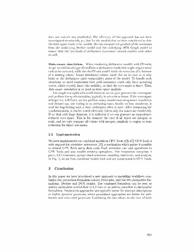
does not contain any deadlocks). The e�ciency of this approach has not beeninvestigated structurally yet, but for the models that we have considered to datethe state space tends to be modest. We can compute the product of the automatafrom the underlying Declare model and the underlying DCR Graph model toensure that the two kinds of declarative constraints cannot con�ict with otheras well.
Data-aware simulation. When combining declarative models with CP-nets,we get an additional type of con�icts: a declarative constraint might require sometask to be executed, while the the CP-net model blocks its execution (f.e. becauseof a missing token). Smart simulation cannot catch this on its own as it onlylooks at the declarative (and computable) parts of the model. To handle suchsituations we need constraints that yield automata which only have acceptingstates, which severely limits the usability, or that the state-space is �nite. Thus,data-aware simulation is as hard as state space analysis.
For simple examples with small domains, we can just generate the state-spaceand perform the synchronization, typically in minutes or hours. If the state-spaceis larger but still �nite, we can perform many simulations using smart simulationand discard any not ending in an accepting state, similar to how simulation isused for bug-�nding until a �nal veri�cation often is used. After computing thesynchronization, it can be stored e�ciently (often only few states are con�icted).If we deal with large domains, it is su�cient if we can generate an equivalence-reduced state-space. This is for example the case if all types are integers orreals, and we only compare all tokens with integers, similarly to region or zonereduction for timed automata.
2.2 Implementation
We have implemented our combined models in CPN Tools 4 [5,17]. CPN Tools 4adds support for simulator extensions [17], a mechanism which makes it possibleto extend CPN Tools using Java code. Each extension can add operations toCPN Tools and also modify existing operations. The integration comprises 4parts: GUI extension, syntax check extension, enabling restriction, and analysis.In Fig. 1, we see how combined models look and are constructed in CPN Tools.
3 Conclusion
In this paper we have introduced a new approach to modelling work�ows com-bining the procedural formalism colored Petri nets, and the two declarative for-malisms, Declare and DCR graphs. The combined formalism can be seen asadding declarative control-�ow to CP-nets or as adding data-�ow to declarativeformalisms. Declarative approaches are typically better for abstract descriptionsor highly dynamic processes, where procedural approaches are better for well-known and structured processes. Combining the two allows us the best of both
264
Fig. 1: Declare and DCR graphs in CPN Tools 4.
worlds and allows declarative processes to also deal with data. We have consid-ered what is needed to provide simulation that avoids future con�icts in e�cientways, and introduce three modes of simulation: simple, smart, and data-aware,where the simple mode only avoids individual con�icts, smart avoids con�ictsnot related to data, and data-aware makes sure that even in the presence ofdata, all executions can terminate successfully. We have brie�y introduced ourimplementation in CPN Tools.
3.1 Related Work
The Guard-Stage-Milestone (GSM) model [8] by Hull et al, which originatedfrom the work on artifact-centric business processes [3], takes an approach tomodelling business processes where a process consists of a number of (possiblynested) stages, which in turn contain a number of tasks. A stage also has guardsand milestones; it is activated by satisfying its guards and through perform-ing the tasks in the stage its milestones can become enabled, which can thenin turn satisfy the guards of other stages. We see the GSM model as a hybridmodel combining procedural and declarative structures in a single language,whereas our approach is based on combining existing procedural and declarativelanguages. In [14] the authors introduce a declarative version of the Computer-Interpretable Guidelines (CIG) language for modelling clinical guidelines, they
265

conclude that because both the procedural and declarative languages have theirdisadvantages it would be best to combine them into a single model, but leavethis for future work. In [16] the authors have examined the understanding ofprocedural and declarative process models by users. In their conclusions theynote that while it appears that procedural models are more comprehensible, itremains uncertain to what extent this is caused by participants being skewedtowards procedural models because of their general acceptance and availability.They do not consider a hybrid approach using both procedural and declarativeconcepts. In [6] Fahland bridges the gap between declarative and proceduralwork�ow approaches by proposing a general compositional mechanism for trans-lating declarative work�ow models to procedural work�ow models. He exem-pli�es the general approach by giving a translation from Declare to Petri nets.The main di�erence to our approach is that while in [6] a declarative model istranslated to a procedural version to facilitate using existing modeling, analysisand management techniques, we aim to combine the declarative and proceduralapproaches and provide tools and techniques for the hybrid approach.
3.2 Future Work
Here we have assumed that a user creates and re�nes a model. Another approachis to have the tool do that. For example, a precedence(A,B) constraint is triviallymodeled using a single place of type boolean, initially marked by false. ThenA changes the value indiscriminately to true and B checks that the value onthe place is true. not co-existence(A,B) can be implemented using a place withthree possible values: {A,B,UNDECIDED}. init(A) is less elegant, but can beimplemented using, e.g., inhibitor arcs. This will not catch con�icts, but we cando that (and translate all constraints in a uniform way) by constructing the �niteautomaton either just equate the states of the automaton with new places oruse a (not data-aware) process mining algorithm [1] or the theory of regions [4]to construct a Petri net for the control �ow. Future work includes investigatingthe best way to make such a translation (semi-)automatically.
The current approach works as long as we describe a single run of a singleprocess. That is, our example in the �gures handles one treatment of one patient.It would be interesting to investigate multiple instances, which would essentiallybe a folding of the current model. We could also have multiple processes com-municate, e.g., like Proclets [2], resulting in a more artifact-driven result. Usinga translation from declarative constraints would essentially result in process-partitioned CP-nets in the sense of [10], which means it would be possible toautomatically derive code from the resulting model. It would also be interest-ing to look into making a proper notion of a process in CP-net models, whereinstances cannot just terminate in any state. This would also include adding anotion of instances to the declarative languages.
266

References
1. van der Aalst, W.: Process Mining: Discovery, Conformance and Enhancement ofBusiness Processes. Springer (2011)
2. van der Aalst, W., Barthelmess, P., Ellis, C.A., Wainer, J.: Work�ow Modelingusing Proclets. In: Proc. of CoopIS'00. pp. 198�209. LNCS, Springer (2000)
3. Bhattacharya, K., Gerede, C., Hull, R., Liu, R., Su, J.: Towards formal analysis ofartifact-centric business process models. In: Proc. of BPM'07. pp. 288�304 (2007)
4. Carmona, J., Cortadella, J., Kishinevsky, M.: A Region-Based Algorithm for Dis-covering Petri Nets from Event Logs. In: Proc. of BPM. LNCS, Springer (2008)
5. CPN Tools webpage. Online: cpntools.org6. Fahland, D.: Towards analyzing declarative work�ows. In: Autonomous and Adap-
tive Web Services. Dagstuhl Seminar Proceedings, vol. 07061, p. 6. InternationalesBegegnungs- und Forschungszentrum fuer Informatik (IBFI) (2007)
7. Hildebrandt, T., Mukkamala, R.R.: Declarative event-based work�ow as dis-tributed dynamic condition response graphs. In: Post-proc.of PLACES 2010 (2010)
8. Hull, R., Damaggio, E., Fournier, F., Gupta, M., Heath, III, F.T., Hobson, S.,Linehan, M., Maradugu, S., Nigam, A., Sukaviriya, P., Vaculin, R.: Introducingthe guard-stage-milestone approach for specifying business entity lifecycles. In:Proc. of WS-FM'10. pp. 1�24. Springer-Verlag, Berlin, Heidelberg (2011)
9. Jensen, K., Kristensen, L.: Coloured Petri Nets � Modelling and Validation ofConcurrent Systems. Springer (2009)
10. Kristensen, L., Westergaard, M.: Automatic Structure-Based Code Generationfrom Coloured Petri Nets: A Proof of Concept. In: Proc. of FMICS. pp. 215�230.LNCS, Springer (2010)
11. Maggi, F., Montali, M., Westergaard, M., Montali, M., van der Aalst, W.: RuntimeVeri�cation of LTL-Based Declarative Process Models. In: Proc. of RV. LNCS, vol.7186, pp. 131�146. Springer (2011)
12. Maggi, F., Montali, M., Westergaard, M., van der Aalst, W.: Monitoring Busi-ness Constraints with Linear Temporal Logic: An Approach Based on ColoredAutomata. In: Proc. of BPM. LNCS, vol. 6896, pp. 132�147. Springer (2011)
13. Mukkamala, R.R.: A Formal Model For Declarative Work�ows - Dynamic Condi-tion Response Graphs. Ph.D. thesis, IT University of Copenhagen (March 2012)
14. Mulyar, N., Pesic, M., van der Aalst, W.M.P., Peleg, M.: Declarative and proce-dural approaches for modelling clinical guidelines: Addressing �exibility issues. In:Proc. of BPM'07. pp. 335�346 (2007)
15. Pesic, M.: Constraint-Based Work�ow Management Systems: Shifting Controls toUsers. Ph.D. thesis, Beta Research School for Operations Management and Logis-tics, Eindhoven (2008)
16. Pichler, P., Weber, B., Zugal, S., Pinggera, J., Mendling, J., Reijers, H.A.: Impera-tive versus declarative process modeling languages: An empirical investigation. In:Proc. of ER-BPM '11. pp. 383�394 (2011)
17. Westergaard, M.: CPN Tools 4: Multi-formalism and Extensibility. Submitted toPetri Nets 2013
18. Westergaard, M.: Better Algorithms for Analyzing and Enacting Declarative Work-�ow Languages Using LTL. In: Proc. of BPM. LNCS, vol. 6896, pp. 83�98. Springer(2011)
19. Westergaard, M., Maggi, F.: Declare: A Tool Suite for Declarative Work�ow Mod-eling and Enactment. In: Business Process Management Demonstration Track (BP-MDemos 2011). CEUR Workshop Proceedings, vol. 820. CEUR-WS.org (2011)
267
The Automated Discovery of Hybrid Processes
Fabrizio Maria Maggi1, Tijs Slaats2,3, and Hajo A. Reijers4,5
1 University of Tartu, Estonia2 IT University of Copenhagen, Denmark
3 Exformatics A/S, Lautrupsgade 13, 2100 Copenhagen, Denmark4 Eindhoven University of Technology, The Netherlands
5 Perceptive Software, The [email protected], [email protected], [email protected]
Abstract. The declarative-procedural dichotomy is highly relevant when choos-ing the most suitable process modeling language to represent a discovered pro-cess. Less-structured processes with a high level of variability can be described ina more compact way using a declarative language. By contrast, procedural pro-cess modeling languages seem more suitable to describe structured and stableprocesses. However, in various cases, a process may incorporate parts that arebetter captured in a declarative fashion, while other parts are more suitable tobe described procedurally. In this paper, we present a technique for discoveringfrom an event log a so-called hybrid process model. A hybrid process model ishierarchical, where each of its sub-processes may be specified in a declarativeor procedural fashion. We have implemented the proposed approach as a plug-inof the ProM platform. To evaluate the approach, we used our plug-in to mine areal-life log from a financial context.
1 Introduction
Process models are an important aid to capture how business operations are organized.One direction to simplify the tasks of creating, maintaining, and reading such mod-els involves the use of declarative techniques for process modeling. In contrast to theprocedural approach, which is dominant for modeling business processes, a declarativeapproach leaves implicit in what exact sequences activities must be carried out. Instead,the emphasis is on the constraints that must be respected in carrying out the process –any behavior that respects these goes. In contexts where activities can be executed inhighly different combinations, a declarative approach arguably produces simpler rep-resentations of the involved process logic. Examples of concrete declarative modelingtechniques are Declare, DCR Graphs [3], and SCIFF.
In [10], we reported that a hybrid process modeling technique was considered bypractitioners as more attractive than a completely declarative or procedural one. Hy-brid, in this context, refers to the potential use of both procedural and declarative modelelements in the same model. The rationale is that the two types of modeling paradigmsallow for a natural fit with different types of process behavior. In places where the pro-cess is highly flexible, a declarative modeling approach leads to a compact and simpledescription of such a “pocket of flexibility” [11]. Instead of describing all the differ-ent types of feasible behavior, the focus is then on ruling out what is not allowed (if
268

anything). By contrast, for parts of the process that are highly structured, a proceduraldescription may be the way to go: It is then simpler to describe what is allowed thanwhat is to be ruled out. For processes that both incorporate structured and unstructuredpockets, a hybrid model delivers a compact and simple description.
This paper should be seen as a direct follow-up to our earlier work. Specifically, wedeveloped a technique to automatically generate a hybrid model from an event log. Thisis a novel contribution, since existing techniques can only generate a process modelthat is either procedural or declarative. By contrast, our technique flexibly alternatesbetween employing a procedural or declarative mining approach in accordance with thenature of the traces it processes. By doing so we are able to avoid the “spaghetti”-likeprocess models that are commonly generated by traditional process mining techniques.
Against this background, the paper is structured as follows. In Section 2, we willoutline the notion of a hybrid model and pinpoint its semantics. Section 3 describesour core contribution, the discovery approach. We will will evaluate this approach inSection 4 on a real-life log. After a discussion of related work, we conclude this paperwith a reflection on the presented work and future steps in Section 6.
2 Semantics of a Hybrid Model
Our interest in this paper is with hybrid models where the procedural and declarativeparts are contained in separate sub-processes. In this sense, there is a resemblance withthe pockets of flexibility concept [11]. A hybrid process consists of a procedural ordeclarative top-level process, which may contain a number of atomic activities as wellas sub-processes. Each sub-process can be either procedural or declarative and maycontain sub-processes of its own. Our approach is applicable to any combination ofprocedural and declarative languages, but in this paper we will apply Petri nets forour procedural models and Declare [9] for our declarative models. Sub-processes areconsidered atomic, meaning that once a sub-processes is started the control is passedfrom the parent process to that sub-process. No other activities can be executed untilthe sub-process has completed. A sub-process can only complete while it is accepting.When exactly it is accepting depends on the language used. In the case of a Petri netthis means reaching a final marking, while for a Declare model it means having noviolated constraints. For the language of a hybrid model we consider the start and com-pletion of sub-processes as silent transitions, which means that there will be no start-and complete-events for the sub-processes in the log. This underlines the fact that thesub-processes are really just a tool for improving the understanding of the process andnot a part of the actual enactment of the process.
3 Discovering Hybrid Process Models
Fig. 1 gives an overview of our approach. In the following paragraphs we describe ourapproach step by step.
Distinguishing Structured and Unstructured Events. We start by separating the eventsof the log into two distinct sets: one containing those events that occur in a structured
269

Find (Un)structured
Events
Divide Log into (Un)structured
SequencesMine Top- level
ProcessCreate Hybrid Process Model
Find Declarative Sub-processes
Mine Procedural Sub-processes
Mine Declarative Sub-processes
Find Procedural Sub-processes
Fig. 1. Overview of our approach
context and one containing those events that occur in an unstructured context. To dis-tinguish structured from unstructured events we use a novel technique, which we referto as context analysis. Our first step is to determine for each event the number of uniquepredecessors and successors to that event. We then consider an event with a large num-ber of both predecessors and successors to be unstructured (according to a user-definedthreshold, in our experimentation we used 4), while an event with a small number ofpredecessors or a small number of successors is considered to be structured. The rea-soning behind these cases is as follows: if an event has a high number of predecessorsand a high number of successors, then there are few rules constraining when exactly theevent can occur. We then consider it likely to fit well into a declarative model. Similarly,if an event has only a small number of predecessors and a small number of successors,then it is probably more easily modeled procedurally, for example, as a sequence or achoice from a low number of options. In the case that an event has a small number ofpredecessors, but a large number of successors, we consider it likely that the event iseither the last element in a structured sequence, which is followed by an unstructuredsequence, or that the event is followed by a choice from a large number of options. Inboth cases it makes sense to consider this as a structured event and model it procedu-rally. Similarly, in the case that an event has a small number of successors, but a largenumber of predecessors we consider it likely that the event is either the first element inan structured sequence, which was preceded by an unstructured sequence, or that theevent joins a choice from a large number of options. In both cases it seems fitting toconsider this as a structured event and model it procedurally.
Dividing the Log into Structured and Unstructured Sequences. The context analysisgives us two sets: one that contains structured events and one that contains unstructuredevents. In the following step, we use these events to identify structured and unstructuredsequences by parsing the log and starting a new sequence whenever an event does notbelong to the same set as its preceding event. After this step, our approach splits into twobranches, one handling the structured sub-logs and the other handling the unstructuredsub-logs.
Finding and Mining procedural Sub-processes. By grouping together each structuredevent with all the direct successors and all the direct predecessors, we obtain a set ofdisjoint clusters of the structured sequences. We then mine procedural sub-processes for
270
each of these clusters. Finally, we abstract the main log by replacing each sequence withthe identifier of the sub-process that it belongs to. It should be noted that the clustersof procedural sequences that are discovered could be further split up using existingclustering techniques. This did not seem necessary on basis of the examples we used inour experimentation with the technique.
Finding and Mining Declarative Sub-processes. For finding declarative sub-processes,we first use an indirect association rule mining algorithm on the set of unstructuredsequences to find declarative patterns. Recall that an indirect association rule can beused to find events that rarely occur together, yet there are other “mediator events” withwhich they appear relatively frequently. We use this type of algorithms since it gives usthe opportunity to not only discover Declare constraints that express positive relations,but also constraints like, for example, not coexistence constraints, which are more likelyto be satisfied when the events involved do not occur together in the same trace. In asecond stage, we use a mining algorithm for standard association rules on the remainingsequences. These rules reflect relationships that exist between events that often co-occurin common transactions. For this reason, these rules allow us to group together eventsthat are very likely connected with each other through positive relations in Declare. Thepatterns are abstracted in the main log, and any remaining event that is at this point notidentified as belonging to a declarative pattern is left as an atomic event.
Mining the Top-level Process. When we are done finding (but not necessarily mining)procedural and declarative sub-processes and have all sub-processes abstracted in themain log, we can then either choose to apply the approach iteratively on the abstractedlog, starting from the first step where we distinguish structured and unstructured activ-ities based on their context, or we can choose to finalize the approach by mining themain log. In the latter case, we compute the average string edit distance for all traces inthe abstract main log and in case of a high similarity among the traces (>50%) we minethe log procedurally using a procedural miner. In case of a lower similarity, we mine itusing a declarative miner. The use of the string edit distance is a simple way to distin-guish between structured and unstructured logs. We validated this approach based onexperiments on synthetic logs. The results of these experiments have shown that tracesin structured logs are more similar to each other with respect to traces in an unstructuredlog. Of course, more sophisticated techniques can be used for discriminating betweenthem.
Creating a Hybrid Process Model. When all mining tasks have finished, we can com-bine the resulting process models into a single hybrid model, based on which abstractactivities in the top-level model correspond to which sub-process. The exact methodwill depend on the miners used and the languages that they use to generate models.In our implementation, we simply generated separate Petri nets and Declare models.However, to improve usability, a tool that supports the visualization and managementof such hybrid models would be needed (for example, to graphically represent a De-clare sub-process within a top-level Petri net model). At this point, this is left for futurework.
271

(a) Alpha Miner (b) Heuristic Miner
(c) ILP Miner
Fig. 2. Procedural Models
4 Evaluation
To evaluate our approach, we have implemented it as a plug-in of the process miningtool ProM.1 For the evaluation, we turned to the real-life event log, which was madeavailable as part of the BPI Challenge 2012.2 The process represented in the event logis an application process for a personal loan within a global financing organization. Thelog itself contains some 262.200 events in 13.087 cases.
Our evaluation took on the following form. We set out to compare a model thatwould result from a traditional mining approach on the selected log with a hybrid modelthat is generated as proposed in this paper. We will refer to these as the procedural andthe hybrid models. The aim then is to compare these models specifically with respectto the understandability of the generated models. We decided to create three proceduralmodels of the event log by using the Alpha, Heuristic, and ILP miner, respectively. Theresulting procedural models are shown in Fig. 2.
We created the hybrid model by using the Declare miner on the clusters of unstruc-tured sequences, while using the Heuristic miner on the clusters of structured sequences.Since the root model in this case also could be classified as structured, it was mined withthe Heuristic miner as well. The hybrid model can be seen in Fig. 3. In this figure, theprocedural root net is shown, as well as links to its sub-nets. Note that two sub-nets areof a declarative nature (D1.1 and D2.1); the other sub-nets are procedural.
To make sure that a comparison with respect to the simplicity of the various modelsis fair, we first reflect on their fitness [13]. This expresses how well the model is ableto “replay” the observed behavior in the log. The values are provided in Table 1. Ascan be seen, the fitness values for the procedural models range from 0.01 for the ILP
1 http://www.promtools.org/prom6/HybridMiner2 http://dx.doi.org/10.4121/uuid:3926db30-f712-4394-aebc-75976070e91f
272

Fig. 3. Hybrid Model
miner to 0.58 for the Alpha miner. For the hybrid model, the fitness values are providedfor each of the sub-nets. These values vary from 0.69 to 1.00 (perfect fitness). Withoutan integrated fitness measure available for hierarchical nets, we propose to take theminimum value as a conservative approximation for the fitness of the hybrid net. Onthis basis, the replay fitness of the hybrid net can be seen to be at least as good asthat of the procedural models. Also, it is not particularly “flower-like", which can be adrawback of aiming at a well-fitting model [13].
A visual inspection of the models seems to indicate that the hybrid model is vastlysimpler than the procedural models. All procedural models can be characterized as“spaghetti-like”. The hybrid model, by contrast, is composed of 9 different sub-nets,each of which having a fairly simple structure. Arguably the most difficult of thesesub-nets are P1.2 and D1.1, which are the largest procedural and declarative sub-nets,respectively. While the modularity of the hybrid model to some extent seems to help theunderstanding of the process, the overall lack of visual clutter is apparent. The proposed
Procedural HybridAlpha Heuristic ILP
Root P1.1 P1.2 P1.3 P1.4 P2.1 P2.2 D1.1 D1.20.58 0.40 0.01 1.00 0.84 0.73 0.69 0.81 1.00 0.86 1.00 1.00
Table 1. Fitness values for the generated models
273
approach, therefore, seems to have the potential to automatically generate behaviorallyaccurate process models that are simple to read.
5 Related Work
Several approaches in the literature focus on the discovery of declarative process mod-els [1,4,2,5,6,7,8]. The algorithms proposed in [4,2,6,8] are tailored to discover Declarespecifications. In particular, the technique proposed in [4,2] is based on a two-step ap-proach. First, the input event log is parsed to generate a knowledge base containing in-formation useful to discover a Declare model. Then, in a second phase, the knowledgebase is queried to find the set of constraints that hold on the input log. The work pro-posed in [6] is based on an Apriori algorithm for association rule mining and has beenused in this paper for the discovery of the declarative sub-processes of a hybrid model.The approaches proposed in [1,5] are more general and allow for the specification ofrules that go beyond the traditional Declare templates. However, these approaches canbe hardly used in real-life settings since they are based on supervised learning tech-niques thus requiring negative examples that are difficult to be derived from real data.In the work proposed in [7], a first-order variant of LTL is used to specify a set of data-aware patterns. Such extended patterns are used as the target language for a processdiscovery algorithm to produce data-aware Declare constraints from raw event logs.
A recent implementation of a hybrid process modeling technique is made availablein CPN Tools 4.0 [15]. Different than what is proposed in the paper at hand, a hybridCPN net allows for the use of procedural and declarative modeling elements within thesame sub-process. Already at an earlier stage, modeling approaches have been proposedthat embrace “pockets of flexibility”. Specifically, in [11] it is proposed to define atbuild-time in a workflow process pockets in a way that is highly similar to a declarativestyle to match their highly flexible behavior; at runtime one has to pick a specific pro-cedural instantiation of the workflow that fits the definition. Two other approaches thatcombine procedural and declarative elements worth noting are Flexibility-as-a-Service(FAAS) [14] and the Guard-Stage-Milestone model [12]. It should be noted that fornone of these approaches automated discovery techniques exist.
6 Conclusion
In this paper, we presented an automated discovery technique for hybrid process mod-els. By analyzing the traces that are available in an event log and clustering them to-gether according to their structure (or lack thereof), we are able to mine the structuredand less structured pockets within a process with procedural and declarative mining al-gorithms, respectively. The result is a hierarchical process model with both proceduraland declarative sub-processes. Our evaluation on a real-life event log suggests that theproposed technique is indeed capable of producing a much simpler representation of aprocess than traditional, purely procedural approaches can.
The proposed approach could be improved along theoretical, technical, and empiri-cal angles. On a theoretical side, there is a need to establish proper metrics that tie to theestablished quality dimensions of fitness, precision, generalization and simplicity [13]
274

for hybrid, hierarchical process models. At this point, it is not entirely clear how a qual-ity measure for a subprocess propagates to the quality of the overall model. Establishingthis will pave the way for a more thorough insight into the strengths and weaknessesof the proposed discovery technique. Technically, a step ahead would be to allow forduplicate events, i.e. the same event can be part of a procedural as well as a declarativesub-process. We did not allow for this at this point, but this could be done by identifying“recurrent" predecessors/successors even if these appear only in a certain percentage ofcases. From an empirical angle, end users need to be confronted with hybrid models fora thorough evaluation of their usefulness and ease of use.
As to stimulate the uptake of hybrid process models, a number of other develop-ments are called for as well. As we pointed out in our earlier work [10], modelingguidelines and tool support will be essential to allow for the manual creation and main-tenance of hybrid process models. We are currently experimenting with such guidelinesand our initial insights are that modelers with an intermediate experience with procedu-ral modeling approaches do not find the composition of hybrid models all that difficult.We hope to report on more substantial insights in the near future.
References1. F. Chesani, E. Lamma, P. Mello, M. Montali, F. Riguzzi, and S. Storari. Exploiting inductive
logic programming techniques for declarative process mining. ToPNoC, 2009.2. Claudio Di Ciccio and Massimo Mecella. A two-step fast algorithm for the automated dis-
covery of declarative workflows. In CIDM, 2013.3. Søren Debois, Thomas Hildebrandt, and Tijs Slaats. Hierarchical declarative modelling with
refinement and sub-processes. In BPM, 2014.4. C. Di Ciccio and M. Mecella. Mining constraints for artful processes. In BIS, 2012.5. E. Lamma, P. Mello, F. Riguzzi, and S. Storari. Applying inductive logic programming to
process mining. In Inductive Logic Programming, volume 4894. 2008.6. F.M. Maggi, R.P.J.C. Bose, and W.M.P. van der Aalst. Efficient discovery of understandable
declarative models from event Logs. In CAiSE, pages 270–285, 2012.7. F.M. Maggi, M. Dumas, L. García-Bañuelos, and M. Montali. Discovering data-aware
declarative process models from event logs. In BPM, pages 81–96, 2013.8. F.M. Maggi, A.J. Mooij, and W.M.P. van der Aalst. User-guided discovery of declarative
process models. In CIDM, pages 192–199, 2011.9. M. Pesic, H. Schonenberg, and W.M.P. van der Aalst. DECLARE: Full Support for Loosely-
Structured Processes. In EDOC 2007, pages 287–298, 2007.10. H.A. Reijers, T. Slaats, and C. Stahl. Declarative modeling – An academic dream or the
future for BPM? In BPM, pages 307–322, 2013.11. S.W. Sadiq, M.E. Orlowska, and W. Sadiq. Specification and validation of process constraints
for flexible workflows. Information Systems, 30(5):349–378, 2005.12. R. Vaculín, R. Hull, T. Heath, C. Cochran, A. Nigam, and P. Sukaviriya. Declarative business
artifact centric modeling of decision and knowledge intensive business processes. In EDOC,pages 151–160, 2011.
13. W.M.P. van der Aalst. Process Mining - Discovery, Conformance and Enhancement of Busi-ness Processes. Springer, 2011.
14. W.M.P. van der Aalst, M. Adams, A.H.M. ter Hofstede, M. Pesic, and H. Schonenberg.Flexibility as a service. In Database Systems for Advanced Applications, 2009.
15. M. Westergaard and T. Slaats. Mixing paradigms for more comprehensible models. InBusiness Process Management, pages 283–290. 2013.
275