Flexible area-color reflective displays based on electric ...
4
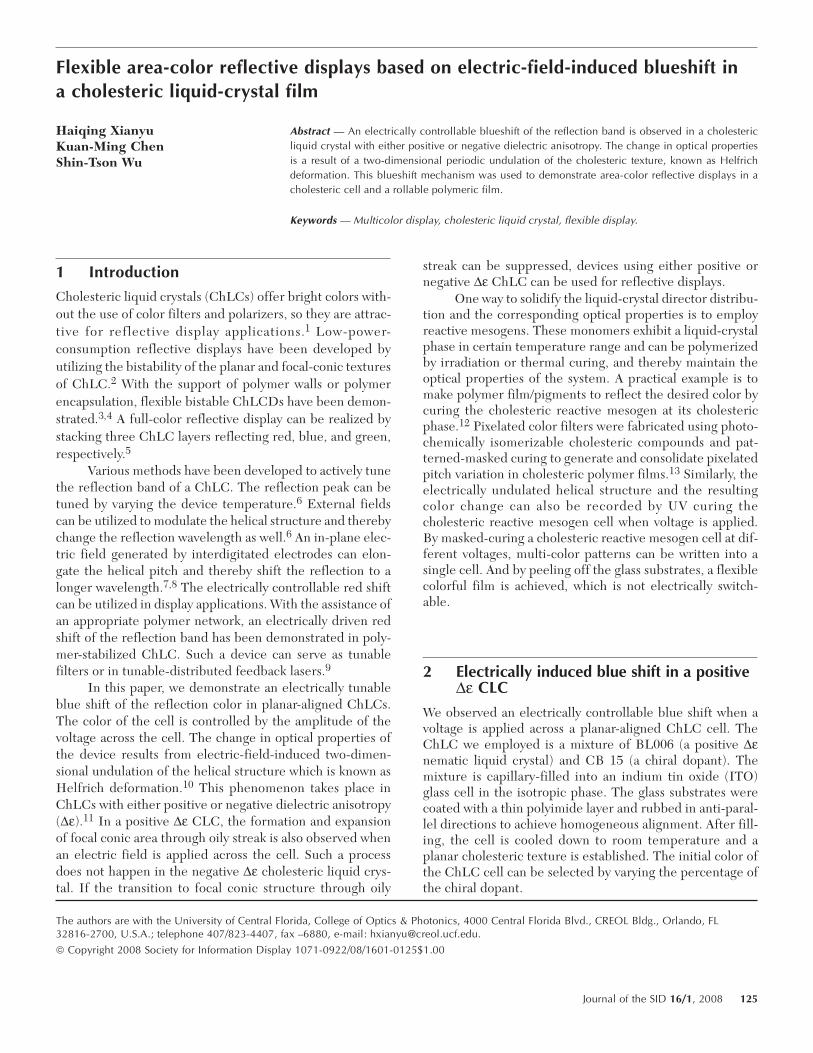
Flexible area-color reflective displays based on electric-field-induced blueshift in a cholesteric liquid-crystal film Haiqing Xianyu Kuan-Ming Chen Shin-Tson Wu Abstract — An electrically controllable blueshift of the reflection band is observed in a cholesteric liquid crystal with either positive or negative dielectric anisotropy. The change in optical properties is a result of a two-dimensional periodic undulation of the cholesteric texture, known as Helfrich deformation. This blueshift mechanism was used to demonstrate area-color reflective displays in a cholesteric cell and a rollable polymeric film. Keywords — Multicolor display, cholesteric liquid crystal, flexible display. 1 Introduction Cholesteric liquid crystals (ChLCs) offer bright colors with- out the use of color filters and polarizers, so they are attrac- tive for reflective display applications. 1 Low-power- consumption reflective displays have been developed by utilizing the bistability of the planar and focal-conic textures of ChLC. 2 With the support of polymer walls or polymer encapsulation, flexible bistable ChLCDs have been demon- strated. 3,4 A full-color reflective display can be realized by stacking three ChLC layers reflecting red, blue, and green, respectively. 5 Various methods have been developed to actively tune the reflection band of a ChLC. The reflection peak can be tuned by varying the device temperature. 6 External fields can be utilized to modulate the helical structure and thereby change the reflection wavelength as well. 6 An in-plane elec- tric field generated by interdigitated electrodes can elon- gate the helical pitch and thereby shift the reflection to a longer wavelength. 7,8 The electrically controllable red shift can be utilized in display applications. With the assistance of an appropriate polymer network, an electrically driven red shift of the reflection band has been demonstrated in poly- mer-stabilized ChLC. Such a device can serve as tunable filters or in tunable-distributed feedback lasers. 9 In this paper, we demonstrate an electrically tunable blue shift of the reflection color in planar-aligned ChLCs. The color of the cell is controlled by the amplitude of the voltage across the cell. The change in optical properties of the device results from electric-field-induced two-dimen- sional undulation of the helical structure which is known as Helfrich deformation. 10 This phenomenon takes place in ChLCs with either positive or negative dielectric anisotropy (∆ε). 11 In a positive ∆ε CLC, the formation and expansion of focal conic area through oily streak is also observed when an electric field is applied across the cell. Such a process does not happen in the negative ∆ε cholesteric liquid crys- tal. If the transition to focal conic structure through oily streak can be suppressed, devices using either positive or negative ∆ε ChLC can be used for reflective displays. One way to solidify the liquid-crystal director distribu- tion and the corresponding optical properties is to employ reactive mesogens. These monomers exhibit a liquid-crystal phase in certain temperature range and can be polymerized by irradiation or thermal curing, and thereby maintain the optical properties of the system. A practical example is to make polymer film/pigments to reflect the desired color by curing the cholesteric reactive mesogen at its cholesteric phase. 12 Pixelated color filters were fabricated using photo- chemically isomerizable cholesteric compounds and pat- terned-masked curing to generate and consolidate pixelated pitch variation in cholesteric polymer films. 13 Similarly, the electrically undulated helical structure and the resulting color change can also be recorded by UV curing the cholesteric reactive mesogen cell when voltage is applied. By masked-curing a cholesteric reactive mesogen cell at dif- ferent voltages, multi-color patterns can be written into a single cell. And by peeling off the glass substrates, a flexible colorful film is achieved, which is not electrically switch- able. 2 Electrically induced blue shift in a positive ∆ε CLC We observed an electrically controllable blue shift when a voltage is applied across a planar-aligned ChLC cell. The ChLC we employed is a mixture of BL006 (a positive ∆ε nematic liquid crystal) and CB 15 (a chiral dopant). The mixture is capillary-filled into an indium tin oxide (ITO) glass cell in the isotropic phase. The glass substrates were coated with a thin polyimide layer and rubbed in anti-paral- lel directions to achieve homogeneous alignment. After fill- ing, the cell is cooled down to room temperature and a planar cholesteric texture is established. The initial color of the ChLC cell can be selected by varying the percentage of the chiral dopant. The authors are with the University of Central Florida, College of Optics & Photonics, 4000 Central Florida Blvd., CREOL Bldg., Orlando, FL 32816-2700, U.S.A.; telephone 407/823-4407, fax –6880, e-mail: [email protected]. © Copyright 2008 Society for Information Display 1071-0922/08/1601-0125$1.00 Journal of the SID 16/1, 2008 125
Transcript of Flexible area-color reflective displays based on electric ...
Flexible area-color reflective displays based on electric-field-induced blueshift ina cholesteric liquid-crystal film
Haiqing XianyuKuan-Ming ChenShin-Tson Wu
Abstract — An electrically controllable blueshift of the reflection band is observed in a cholestericliquid crystal with either positive or negative dielectric anisotropy. The change in optical propertiesis a result of a two-dimensional periodic undulation of the cholesteric texture, known as Helfrichdeformation. This blueshift mechanism was used to demonstrate area-color reflective displays in acholesteric cell and a rollable polymeric film.
Keywords — Multicolor display, cholesteric liquid crystal, flexible display.
1 IntroductionCholesteric liquid crystals (ChLCs) offer bright colors with-out the use of color filters and polarizers, so they are attrac-tive for reflective display applications.1 Low-power-consumption reflective displays have been developed byutilizing the bistability of the planar and focal-conic texturesof ChLC.2 With the support of polymer walls or polymerencapsulation, flexible bistable ChLCDs have been demon-strated.3,4 A full-color reflective display can be realized bystacking three ChLC layers reflecting red, blue, and green,respectively.5
Various methods have been developed to actively tunethe reflection band of a ChLC. The reflection peak can betuned by varying the device temperature.6 External fieldscan be utilized to modulate the helical structure and therebychange the reflection wavelength as well.6 An in-plane elec-tric field generated by interdigitated electrodes can elon-gate the helical pitch and thereby shift the reflection to alonger wavelength.7,8 The electrically controllable red shiftcan be utilized in display applications. With the assistance ofan appropriate polymer network, an electrically driven redshift of the reflection band has been demonstrated in poly-mer-stabilized ChLC. Such a device can serve as tunablefilters or in tunable-distributed feedback lasers.9
In this paper, we demonstrate an electrically tunableblue shift of the reflection color in planar-aligned ChLCs.The color of the cell is controlled by the amplitude of thevoltage across the cell. The change in optical properties ofthe device results from electric-field-induced two-dimen-sional undulation of the helical structure which is known asHelfrich deformation.10 This phenomenon takes place inChLCs with either positive or negative dielectric anisotropy(∆ε).11 In a positive ∆ε CLC, the formation and expansionof focal conic area through oily streak is also observed whenan electric field is applied across the cell. Such a processdoes not happen in the negative ∆ε cholesteric liquid crys-tal. If the transition to focal conic structure through oily
streak can be suppressed, devices using either positive ornegative ∆ε ChLC can be used for reflective displays.
One way to solidify the liquid-crystal director distribu-tion and the corresponding optical properties is to employreactive mesogens. These monomers exhibit a liquid-crystalphase in certain temperature range and can be polymerizedby irradiation or thermal curing, and thereby maintain theoptical properties of the system. A practical example is tomake polymer film/pigments to reflect the desired color bycuring the cholesteric reactive mesogen at its cholestericphase.12 Pixelated color filters were fabricated using photo-chemically isomerizable cholesteric compounds and pat-terned-masked curing to generate and consolidate pixelatedpitch variation in cholesteric polymer films.13 Similarly, theelectrically undulated helical structure and the resultingcolor change can also be recorded by UV curing thecholesteric reactive mesogen cell when voltage is applied.By masked-curing a cholesteric reactive mesogen cell at dif-ferent voltages, multi-color patterns can be written into asingle cell. And by peeling off the glass substrates, a flexiblecolorful film is achieved, which is not electrically switch-able.
2 Electrically induced blue shift in a positive∆ε CLC
We observed an electrically controllable blue shift when avoltage is applied across a planar-aligned ChLC cell. TheChLC we employed is a mixture of BL006 (a positive ∆εnematic liquid crystal) and CB 15 (a chiral dopant). Themixture is capillary-filled into an indium tin oxide (ITO)glass cell in the isotropic phase. The glass substrates werecoated with a thin polyimide layer and rubbed in anti-paral-lel directions to achieve homogeneous alignment. After fill-ing, the cell is cooled down to room temperature and aplanar cholesteric texture is established. The initial color ofthe ChLC cell can be selected by varying the percentage ofthe chiral dopant.
The authors are with the University of Central Florida, College of Optics & Photonics, 4000 Central Florida Blvd., CREOL Bldg., Orlando, FL32816-2700, U.S.A.; telephone 407/823-4407, fax –6880, e-mail: [email protected].
© Copyright 2008 Society for Information Display 1071-0922/08/1601-0125$1.00
Journal of the SID 16/1, 2008 125

Figure 1 shows the reflection microscope photos andreflection spectra of a 5-µm cell at different voltages. Whenno voltage is applied, the liquid crystal has a perfect planartexture and shows a selective reflection to right-handed cir-cularly polarized light centered at ~650 nm, as shown inFig. 1(a). A 100-Hz ac voltage is utilized to address the cell.When the applied voltage is greater than ~10 Vrms, a two-dimensional periodic undulation of the helical structure takesplace, resulting in color change. At V = 13 Vrms, the cell colorturns to yellowish as shown in the left side of Fig. 1(b). Thereflection spectrum presented on the right side of Fig. 1(b)indicates that the reflection peak shifts toward a shorterwavelength, but its bandwidth is broadened and peak reflec-tance decreased. The color of the cell appears greenish, asFig. 1(c) shows, when the voltage is increased to 16.5 V, butits peak reflectance is further decreased. If we keep increas-ing the voltage across the cell, the ChLC will be turned intothe focal-conic state and then the homeotropic state, nei-ther of which exhibits selective reflection.
The two-dimensional periodic undulation is the elec-trically induced Helfrich deformation. Such a change in tex-ture happens when the voltage is higher than the thresholdvalue:1
(1)
where K22 and K33 are the twist and bend elastic constantsof the ChLC, h is the cell gap, and P0 is the pitch length atzero field. The spatial period of the undulation is10
(2)
In the first-order perturbation approximation, the undulatedpitch length is given by10
(3)
where P is the local pitch length, the z axis is the cell normaldirection, the x axis is parallel to the cell surface, and τ0 isthe perturbation amplitude which depends on the electricfield. The inhomogeneity of the helical pitch, as describedby Eq. (3), results in the broadening of the reflection peakand the decrease of peak reflectance. Once the voltage isremoved, the undulation will disappear and the cell will fallback to the original planar texture.
Another electrically induced change in cholesterictexture, the transition to focal-conic texture through oilystreak, also takes place when a voltage is applied. The darkarea in the upper right corner of Fig. 1(c) (left) is the oilystreak/focal-conic region. The threshold voltage of the oilystreak is lower than that of the Helfrich deformation due tothe defects in the planar texture. The formation of oilystreak is slower than the Helfrich deformation. However,the entire cell will turn into the focal-conic state through theformation of oily streak. To suppress the formation andexpansion of the focal conic region, the following factors arehelpful to avoid using cell spacers, to eliminate defects andinhomogeneity in alignment layers, to improve cell-gaphomogeneity, and to choose an appropriate ChLC. If thetransition to focal-conic texture through oily streak can becontrolled, this device would be useful for multi-color reflec-tive displays.
3 Electrically induced blue shift in anegative ∆ε ChLC
The electrically induced blue shift also occurs in planar-aligned ChLC with negative dielectric anisotropy, whichwas theoretically predicted and experimentally observed inthe 1970s.11,14 This phenomenon can also be used to realizecontrollable optical performance tuning. A mixture of ZLI-4788 (Merck, ∆n = 0.1647 at λ = 589 nm and ∆ε = –5.7 atf = 1 kHz) and S1011 (a chiral dopant) was capillary-filledinto a 5-µm ITO-glass homogeneous cell. As depicted inFig. 2(a) (left), the cell shows a perfect planar texture whenno external field is present. The reflection spectrum in theright side of Fig. 2(a) confirms this observation.
During experiments, we used a 100-Hz ac voltage todrive the cell. When the applied voltage exceeds ~25.5
VK K h
PHelfrich =4 2 22 33
1 2
0 0
p( ),
Dee
l = ( ) ( ) .2 33 221 4
01 2K K P h
21 1
00p t p p
lP Pz
hx-
FHG
IKJ = F
HGIKJ
FHG
IKJsin cos ,
FIGURE 1 — The reflective microscope photos (left) and reflectionspectra (right) of a 5-µm planar-aligned cell filled with a positive ∆ε ChLCat different voltages.
126 Xianyu et al. / Flexible area-color reflective displays based on electric-field-induced blueshift
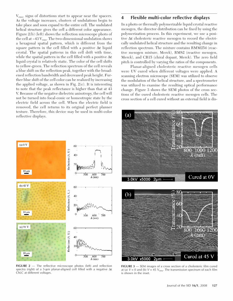
Vrms, signs of distortions start to appear near the spacers.As the voltage increases, clusters of undulations begin totake place and soon expand to the entire cell. The undulatedhelical structure gives the cell a different color appearance.Figure 2(b) (left) shows the reflection microscope photo ofthe cell at ~43 Vrms. The two-dimensional undulation showsa hexagonal spatial pattern, which is different from thesquare pattern in the cell filled with a positive ∆ε liquidcrystal. The spatial patterns in this cell drift with time,while the spatial pattern in the cell filled with a positive ∆εliquid crystal is relatively static. The color of the cell shiftsto yellow-green. The reflection spectrum of the cell revealsa blue shift on the reflection peak, together with the broad-ened reflection bandwidth and decreased peak height. Fur-ther blue shift of the cell color can be realized by increasingthe applied voltage, as shown in Fig. 2(c). It is interestingto note that the peak reflectance is higher than that at 43V. Because of the negative dielectric anisotropy, the cell willnot be turned into focal-conic or homeotropic state by theelectric field across the cell. When the electric field isremoved, the cell returns to its original perfect plannertexture. Therefore, this device may be used in multi-colorreflective displays.
4 Flexible multi-color reflective displaysIn a photo or thermally polymerizable liquid crystal reactivemesogen, the director distribution can be fixed by using thepolymerization process. In this experiment, we use a posi-tive ∆ε cholesteric reactive mesogen to record the electri-cally undulated helical structure and the resulting change inreflection spectrum. The mixture contains RMM254 (reac-tive mesogen mixture, Merck), RM82 (reactive mesogen,Merck), and CB15 (chiral dopant, Merck). The zero fieldpitch is controlled by varying the ratios of the components.
Planar-aligned cholesteric reactive mesogen cellswere UV cured when different voltages were applied. Ascanning electron microscope (SEM) was utilized to observethe modulation of the helical structure, and a spectrometerwas utilized to examine the resulting optical performancechange. Figure 3 shows the SEM photos of the cross sec-tions of the cured cholesteric reactive mesogen cells. Thecross section of a cell cured without an external field is dis-
FIGURE 2 — The reflective microscope photos (left) and reflectionspectra (right) of a 5-µm planar-aligned cell filled with a negative ∆εChLC at different voltages.
FIGURE 3 — SEM images of a cross section of a cholesteric film curedat (a) V = 0 and (b) V = 45 Vrms. The transmission spectrum of each filmis shown in the inset.
Journal of the SID 16/1, 2008 127

played in Fig. 3(a). The uniform layered structure indicatesa perfect planar texture with homogeneous pitch distribu-tion. The corresponding transmission spectrum, as shown inthe inset of Fig. 3(a), confirms this configuration. Figure3(b) shows an undulated structure when the cell was curedat 45 Vrms. The change in director distribution leads to thechange in transmission spectrum: the blue shift of the trans-mission notch and the expansion of notch width, as shown inthe inset of Fig. 3(b). The correlation between thecholesteric texture and optical properties is clearly estab-lished by this comparison.
The SEM image in Fig. 3(b) shows that the undulatedtexture does not exactly follow the first-order sinusoidalperturbation suggested by Helfrich. The variation incholesteric pitch and in the tilt angle of cholesteric layers isnot always minimized at cell substrates, which is indicatedby Eq. (3). A better theoretical model for understanding thedirector undulation mechanisms and their associated opti-cal-property change remain to be developed.
The electrically induced color change in cholestericreactive-mesogen cells can be permanently recordedthrough UV curing when the voltage is applied.15 An area-color pattern can be recorded into a single cell by maskedcuring each part when different voltages are applied. Thefilm thickness is controlled by the cell gap, which is 8 µm inour experiment. The glass substrates can be peeled off anda flexible film with area-color pattern is fabricated. Figure 4shows a polymer film with three characters “LCD” writtenin; with each character in a different color. This film can bebent and conformed to a curved surface, as exhibited inFig. 4(b). The above process can be applied to producefilms for decoration and to write security marks. However,once cured the displayed images cannot be switched by anelectric field.
5 ConclusionsWe have demonstrated electrically controllable blue shift ina planar-aligned ChLC with either positive or negative dielec-tric anisotropy. The optical performance change originatesfrom a two-dimensional periodic undulation of the planartexture. The device filled with a negative ∆ε ChLC can beused in reflective color display. If the transition to focal-conic texture through oily streak can be suppressed in pla-nar aligned cells filled with a positive ∆ε ChLC, such adevice can also be used in reflective displays. The electri-cally tuned color change can be solidified by curing thecholesteric reactive mesogen when the voltage is applied.By masked curing at different voltages, multiple color pat-terns can be recorded into a flexible polymer thin film,which can be used as a decoration film or security prints.
References1 S. T. Wu and D. K. Wu, Reflective Liquid Crystal Displays (Wiley, New
York, 2001).2 D. K. Yang, J. L. West, L. C. Chien, and J. W. Doane, J. Appl. Phys.
76, 1331 (1994).3 D. K. Yang, J. Display Technol. 2, 32 (2006).4 A. Kahn, T. Schneider, E. Montbach, D. J. Davis, N. Miller, D. Mar-
hefka, T. Ernst, and J. W. Doane, SID Symposium Digest Tech. Papers38, 54 (2007).
5 X. Y. Huang, A. A. Khan, D. J. Davis, G. M. Podojil, C. M. Jones, N.Miller, and J. W. Doane, Proc. SPIE 3635, 120 (1999).
6 P. G. de Gennes and J. Prost, The Physics of Liquid Crystals, 2nd ed.(Clarendon Press, Oxford, 1993), pp. 280–294.
7 Z. Li, P. Desai, R. B. Akins, G. Ventouris, and D. Voloschenko, Proc.SPIE 4658, 7 (2002).
8 H. Xianyu, S. Faris, and G. P. Crawford, Appl. Opt. 43, 5006 (2004).9 H. P. Yu, B. Y. Tang, J. H. Li, and L. Li, Opt. Express 13, 7243 (2005).
10 W. Helfrich, J. Chem. Phys. 55, 839 (1971).11 J. P. Hurault, J. Chem. Phys. 59, 2068 (1973).12 J. Lub, D. J. Broer, R. A. M. Hikmet and K. G. J. Nierop, Liq. Cryst.
18, 319 (1995).13 J. Lub, D. J. Broer, and P. van de Witte, Prog. Organic Coatings 45,
211 (2002).14 F. Rondelez, H. Arnould, and C. J. Gerritsma, Phy. Rev. Lett. 28, 735
(1972).15 H. Xianyu, T. H. Lin, and S. T. Wu, Appl. Phys. Lett. 89, 091124 (2006).
FIGURE 4 — A three-color rollable cholesteric polymer film: (a) beforebending and (b) when the film is attached to a cylindrical post holder.The “LCD” characters were exposed when different voltages wereapplied. The film thickness is 8 µm.
128 Xianyu et al. / Flexible area-color reflective displays based on electric-field-induced blueshift