FLEXA - SUBRACK SYSTEM
40
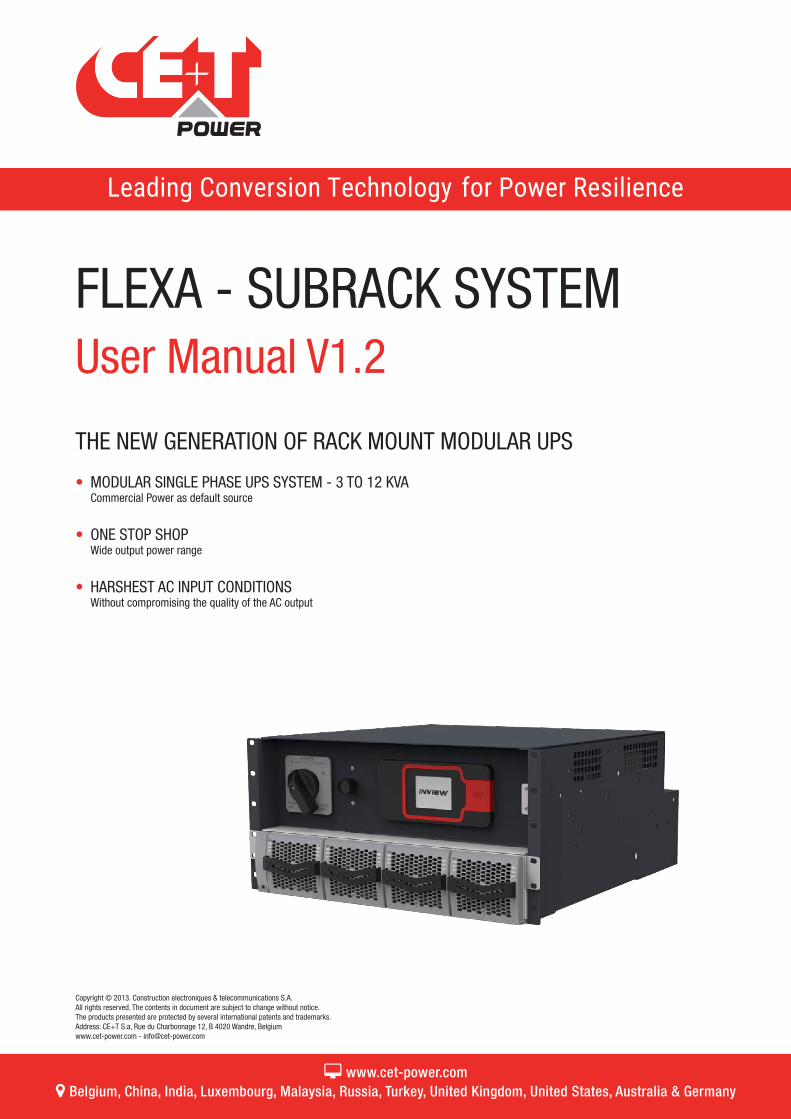
Copyright © 2013. Construction electroniques & telecommunications S.A. All rights reserved. The contents in document are subject to change without notice. The products presented are protected by several international patents and trademarks. Address: CE+T S.a, Rue du Charbonnage 12, B 4020 Wandre, Belgium www.cet-power.com - [email protected] FLEXA - SUBRACK SYSTEM User Manual V1.2 THE NEW GENERATION OF RACK MOUNT MODULAR UPS • MODULAR SINGLE PHASE UPS SYSTEM - 3 TO 12 KVA Commercial Power as default source • ONE STOP SHOP Wide output power range • HARSHEST AC INPUT CONDITIONS Without compromising the quality of the AC output www.cet-power.com Belgium, China, India, Luxembourg, Malaysia, Russia, Turkey, United Kingdom, United States, Australia & Germany
Transcript of FLEXA - SUBRACK SYSTEM
Copyright © 2013. Construction electroniques & telecommunications S.A. All rights reserved. The contents in document are subject to change without notice.The products presented are protected by several international patents and trademarks.Address: CE+T S.a, Rue du Charbonnage 12, B 4020 Wandre, Belgiumwww.cet-power.com - [email protected]
FLEXA - SUBRACK SYSTEMUser Manual V1.2
THE NEW GENERATION OF RACK MOUNT MODULAR UPS
• MODULAR SINGLE PHASE UPS SYSTEM - 3 TO 12 KVACommercial Power as default source
• ONE STOP SHOP Wide output power range
• HARSHEST AC INPUT CONDITIONSWithout compromising the quality of the AC output
www.cet-power.com Belgium, China, India, Luxembourg, Malaysia, Russia, Turkey, United Kingdom, United States, Australia & Germany
2 – Flexa – Subrack System – User Manual – v1.2
Table of content1. CE+T at a glance ................................................................................................................................... 5
2. Abbreviations ........................................................................................................................................ 6
3. Warranty and Safety Conditions ............................................................................................................. 73.1 Disclaimer ................................................................................................................................... 73.2 Technical care ............................................................................................................................. 73.3 Installation .................................................................................................................................. 8
3.3.1 Handling ......................................................................................................................... 83.3.2 Surge and transients ...................................................................................................... 93.3.3 Other .............................................................................................................................. 9
3.4 Maintenance .............................................................................................................................. 93.5 Replacement and Dismantling ..................................................................................................... 9
4. Flexa Module - Technology ..................................................................................................................... 10
5. Introduction ........................................................................................................................................... 115.1 Overview ..................................................................................................................................... 115.2 System Specifications ................................................................................................................. 125.3 System Description ..................................................................................................................... 13
6. Components .......................................................................................................................................... 156.1 Flexa Module ............................................................................................................................... 156.2 Controller - Inview S .................................................................................................................... 15
6.2.1 Inview S - Connections ................................................................................................... 166.3 Measure Box Battery ................................................................................................................... 166.4 Manual By-Pass .......................................................................................................................... 17
7. Installation ............................................................................................................................................. 187.1 Unpacking the system ................................................................................................................. 187.2 Installing the System into a Cabinet ............................................................................................. 187.3 Electrical Installation ................................................................................................................... 19
7.3.1 Pre-requisites ................................................................................................................. 197.3.2 Cable Routing and Fixation ............................................................................................. 197.3.3 Power Terminals ............................................................................................................. 197.3.4 Battery connection ......................................................................................................... 207.3.5 AC Input connection ....................................................................................................... 207.3.6 AC Output connection ..................................................................................................... 207.3.7 Grounding ...................................................................................................................... 207.3.8 Signalling ....................................................................................................................... 21
8. Operation ............................................................................................................................................... 228.1 Flexa module ............................................................................................................................... 228.2 Inview S - LCD Display ................................................................................................................ 23
8.2.1 LED indications .............................................................................................................. 238.2.2 Menu structure ............................................................................................................... 24
3 – Flexa – Subrack System – User Manual – v1.2
8.3 Inview S - Web Interface .............................................................................................................. 248.3.1 Login .............................................................................................................................. 248.3.2 Interface Areas ............................................................................................................... 25
9. System Start-up .................................................................................................................................... 279.1 Installation Check ........................................................................................................................ 279.2 Start-up ...................................................................................................................................... 27
10. Replacement procedures ...................................................................................................................... 3010.1 Flexa module ............................................................................................................................... 30
10.1.1 Removal ......................................................................................................................... 3010.1.2 Inserting ......................................................................................................................... 30
10.2 Fan replacement ......................................................................................................................... 3110.3 Inview S - Panel Mounting ........................................................................................................... 32
11. Manual By-Pass Operation ..................................................................................................................... 3311.1 Pre requisites .............................................................................................................................. 3311.2 Manual By-Pass Operation ......................................................................................................... 33
11.2.1 Normal to By-Pass, Engage MBP .................................................................................... 3311.2.2 By-Pass to Normal, Disengage MBP ............................................................................... 34
12. Commissioning ..................................................................................................................................... 35
13. Trouble Shooting and Defective Situations Resolution ............................................................................ 3613.1 Trouble Shooting ......................................................................................................................... 36
14. Service ................................................................................................................................................. 37
15. Maintenance Task ................................................................................................................................. 3815.1 Spare Parts ................................................................................................................................. 38
16. Annexe 1: Inview S and MBB wiring diagram ......................................................................................... 39
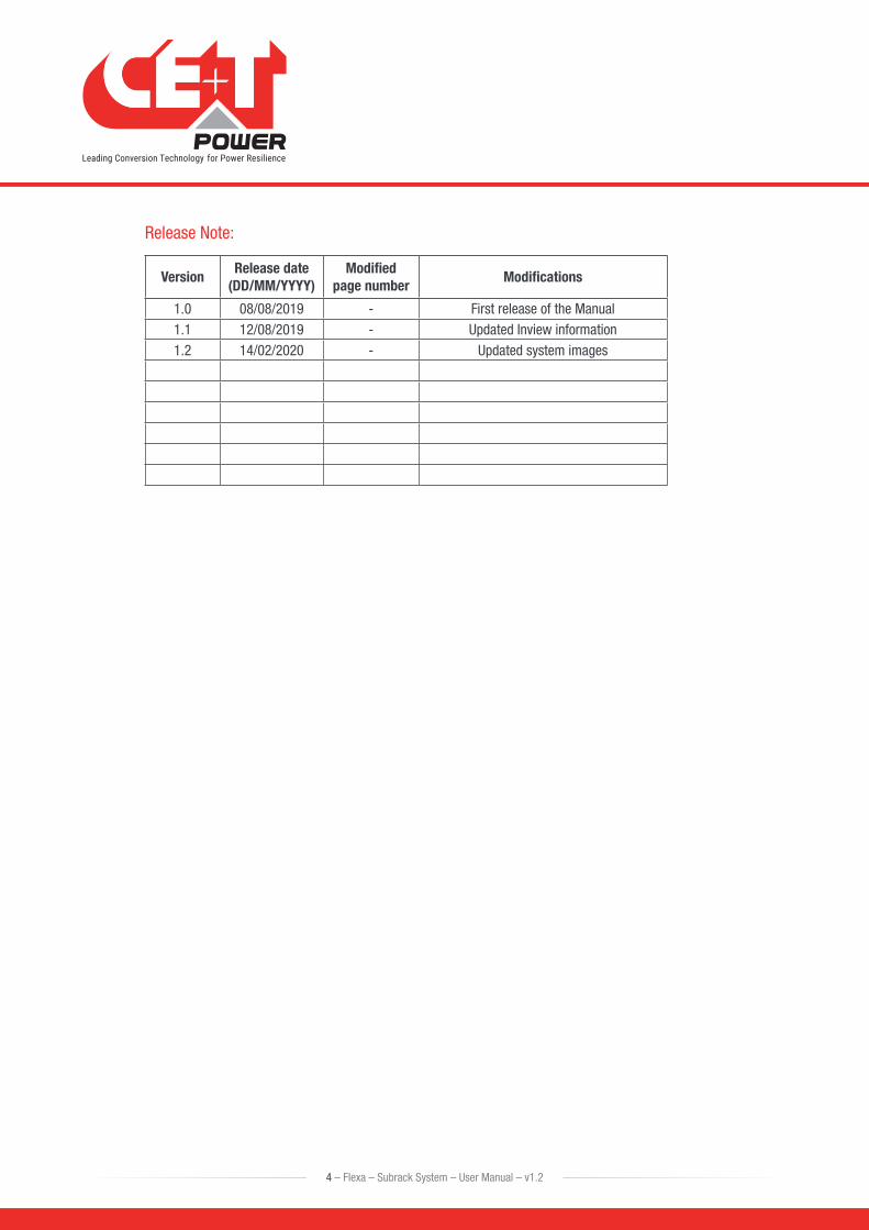
Release Note:
VersionRelease date
(DD/MM/YYYY)Modified
page numberModifications
1.0 08/08/2019 - First release of the Manual1.1 12/08/2019 - Updated Inview information1.2 14/02/2020 - Updated system images
4 – Flexa – Subrack System – User Manual – v1.2
1. CE+T at a glanceCE+T Power designs, manufactures and markets a range of products for industrial operators with mission critical applications, who are not satisfied with existing AC and DC backup systems performances, and related maintenance costs.
Our product is an innovative AC and DC backup solution that unlike most used UPS’s
• Maximizes the operator’s applications uptime;
• Operates with lowest OPEX;
• Provides best protection to disturbances;
• Optimizes footprint.
Our systems are:
• Modular
• Truly redundant
• Highly efficient
• Maintenance free
• Battery friendly
CE+T power puts 60+ years expertise in power conversion together with worldwide presence to provide customized solutions and extended service 24/7 - 365.
5 – Flexa – Subrack System – User Manual – v1.2
CE+T at a glance
2. Abbreviations ECI Enhanced Conversion Innovation
EPC Enhanced Power Conversion
REG Regular
DSP Digital Signal Processor
AC Alternating current
DC Direct current
PE Protective Earth (also called Main Protective Conductor)
N Neutral
PCB Printed Circuit Board
TRS True Redundant Structure
PWR Power
ESD Electro Static Discharge
MET Main Earth Terminal
MBP Manual By-pass
MBB Measure Box Battery
TCP/IP Transmission Control Protocol/Internet Protocol
USB Universal Serial Bus
LAN Local Access Network
ETH Ethernet
SNMP Simple Network Management Protocol
HTTP HyperText Transfer Protocol
HTTPS Secure HyperText Transfer Protocol
NTP Network Time Protocol
MIB Management Information Base
DHCP Dynamic Host Configuration Protocol
6 – Flexa – Subrack System – User Manual – v1.2
Abbreviations
3. Warranty and Safety Conditions*
WARNING:
The electronics in the power supply system are designed for an indoor, clean environment.
When installed in a dusty and/or corrosive environment, outdoor or indoor, it is important to:
• Install an appropriate filter on the enclosure door, or on the room’s air conditioning system.
• Keep the enclosure door closed during operation.
• Replace the filters on a regular basis.
Important Safety Instructions and Save These Instructions.
3.1 Disclaimer • The manufacturer declines all responsibilities if equipment is not installed, used or operated according to the
instructions herein by skilled technicians according to local regulations.
• Warranty does not apply if the product is not installed, used and handled according to the instructions in the manuals.
3.2 Technical care • This electric equipment can only be repaired or maintained by a “qualified employee” with adequate training.
Even personnel who are in charge of simple repairs or maintenance are required to have knowledge or experience related to electrical maintenance.
• Please follow the procedures contained in this Manual, and note all the “DANGER”, “WARNING” AND “NOTICE” marks contained in this manual. Warning labels must not be removed.
• Qualified employees are trained to recognize and avoid any dangers that might be present when working on or near exposed electrical parts.
• Qualified employees should know how to lock out and tag out machines, so the machines will not accidentally be turned on and injure employees working on them.
• Qualified employees also understand safety related work practices, including those by OSHA and NFPA, as well as knowing what personal protective equipment should be worn.
• All operators are to be trained to perform the emergency shut-down procedure.
• Operating ambient temperature is -20°C to 50°C.
• This unit is intended for installation in a temperature-regulated, indoor area that is relatively free of conductive contaminants.
• Never wear metallic objects such as rings, watches, or bracelets during installation, service or maintenance of the product.
• This product is suitable for use in a computer room.
* These instructions are valid for most CE+T Products/Systems. Some points might however not be valid for the product described in this manual
7 – Flexa – Subrack System – User Manual – v1.2
Warranty and Safety Conditions
• CAUTION – Risk of electric shock. Capacitors store hazardous energy. Do not remove cover until 5 minutes after disconnecting all sources of supply.
• CAUTION – Risk of electric shock. This Converter / UPS receives power from more than one source. Disconnection of the AC source and DC source is required to de-energize this unit before servicing.
• CAUTION - For continued protection against risk of fire, replace only with same type and rating of fuse.
• Insulated tools must be used at all times when working with live systems.
• When handling the system/units pay attention to sharp edges.
3.3 Installation • This product is intended to be installed only in a restricted access area as accordance with the National
Electrical Code ANSI/NFPA 70, or equivalent local agencies.
• The system may contain output over-current protection in the form of circuit breakers. In addition to these circuit breakers, the user must observe the recommended upstream and downstream circuit breaker requirements as defined in this manual.
• Please use extreme caution when accessing circuits that may be at hazardous voltages or energy levels.
• The system rack is a dual input power supply. The complete system shall be wired in a way that both input and output leads can be made powerfree in a single action.
• REG systems can be seen as independent power sources. To comply with local and international safety standards N (output) and PE shall be bonded.
• EPC system that have no AC input wired and connected to comply with local and international safety standards N (output) and PE shall be bonded. The bonded between N output and L must be removed once the AC input is being connected.
• When AC Mains is not connected, the output AC circuit is considered as a separately-derived source. If local codes require grounding of this circuit, use the identified terminal for bonding this circuit to the enclosure. Ground the enclosure to a suitable grounding electrode in accordance with local code requirements.
• Use 90°C copper wires / conductors only.
• AC and DC circuits shall be terminated with no voltage / power applied.
• The safety standard IEC/EN62040-1-1 requires that, in the event of an output short circuit, the converter must disconnect in 5 seconds. The parameter can be adjusted on onitoring ; however, if the parameter is set at a value > 5 seconds, an external protection must be provided so that the short circuit protection operates within 5 seconds. Default setting is 60 seconds.
• All illustrations in the manual are for general reference, Refer to the technical drawing which is received along with the system for exact information.
3.3.1 Handling
• The cabinet shall not be lifted using lifting eyes.
• Remove weight from the cabinet by unplugging the converters. Mark converters clearly with shelf and position for correct rebuild. This is especially important in dual or three phase configurations.
• Empty converter positions must not be left open. Replace either with module or dummy cover.
8 – Flexa – Subrack System – User Manual – v1.2
Warranty and Safety Conditions
3.3.2 Surge and transients
The mains (AC) supply of the modular converter system shall be fitted with Lightning surge suppression and Transient voltage surge suppression suitable for the application at hand. Manufacturer’s recommendations of installation shall be adhered to. Selecting a device with an alarm relay for function failure is advised.
Indoor sites are considered to have a working lightning surge suppression device in service.
• Indoor sites Min Class II.
• Outdoor sites Min Class I + Class II or combined Class I+II.
Note:
Choosing and installing surge arrestors must obey to precise technical rules. Distance to equipment to protect, cable gage and cable routing have significant influence on proper device service.
Some areas are more susceptible to be hit by electrical strikes, especially when altitude increases.
Good earthing is also crucial for surge arrestors to work properly.
CE+T declines any liability in regard to damaged caused to equipment not correctly or not sufficiently protected.
3.3.3 Other • Isolation test (Hi-Pot) must not be performed without instructions from the manufacturer.
3.4 Maintenance • The converter system/rack can reach hazardous leakage currents. Earthing must be carried out prior to
energizing the system. Earthing shall be made according to local regulations.
• Prior to any work conducted to a system/unit, make sure that AC input voltage and Battery are disconnected.
• Prior to accessing the system or modules, make sure all source of supply is disconnected. CAUTION – Risk of electric shock. Capacitors store hazardous energy. Do not remove cover until 5 minutes after disconnecting all sources of supply.
• Some components and terminals carry high voltage during operation. Contact may result in fatal injury.
3.5 Replacement and Dismantling • ESD Strap must be worn when handling PCB’s and open units.
• The converter system/rack is not supplied with internal disconnect devices on input nor output
• CE+T cannot be held responsible for disposal of the converter system and therefore the customer must segregate and dispose of the materials which are potentially harmful to the environment, in accordance with the local regulations in force in the country of installation.
• If the equipment is dismantled to dispose of its component products, you must comply with the local regulations in force in the country of destination and in any case avoid causing any kind of pollution.
To download the latest documentation and software, please visit our website at www.cet-power.com
9 – Flexa – Subrack System – User Manual – v1.2
Warranty and Safety Conditions
10 – Flexa – Subrack System – User Manual – v1.2
Flexa Module - Technology
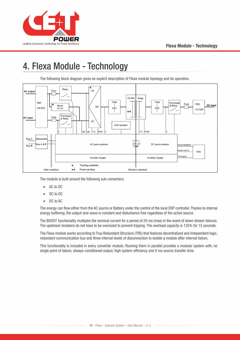
4. Flexa Module - TechnologyThe following block diagram gives an explicit description of Flexa module topology and its operation.
The module is built around the following sub-converters:
• AC to DC
• DC to DC
• DC to AC
The energy can flow either from the AC source or Battery under the control of the local DSP controller. Thanks to internal energy buffering, the output sine wave is constant and disturbance free regardless of the active source.
The BOOST functionality multiples the nominal current for a period of 20 ms (max) in the event of down stream failures. The upstream breakers do not have to be oversized to prevent tripping. The overload capacity is 125% for 15 seconds.
The Flexa module works according to True Redundant Structure (TRS) that features decentralized and independent logic, redundant communication bus and three internal levels of disconnection to isolate a module after internal failure.
This functionality is included in every converter module. Running them in parallel provides a modular system with, no single point of failure, always-conditioned output, high system efficiency and 0 ms source transfer time.
5. Introduction
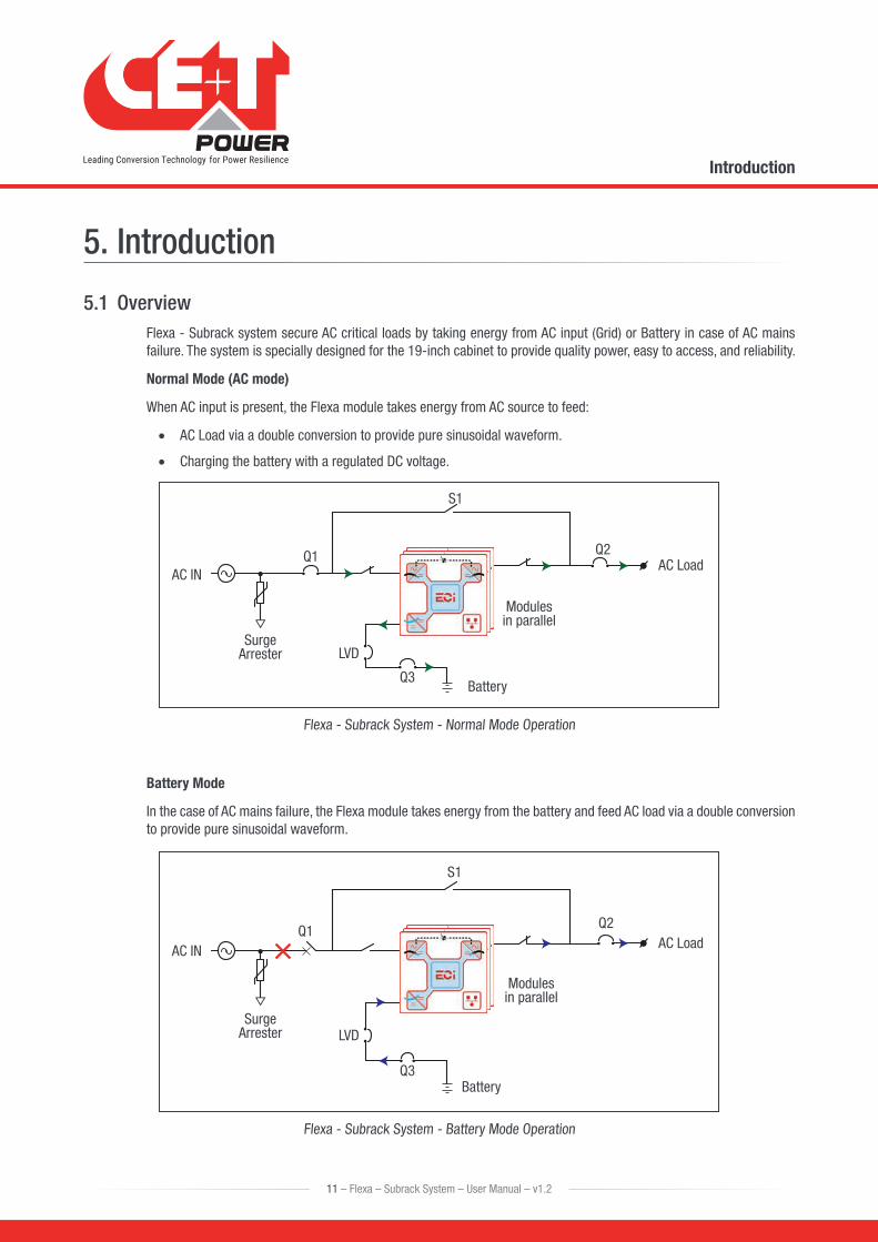
5.1 OverviewFlexa - Subrack system secure AC critical loads by taking energy from AC input (Grid) or Battery in case of AC mains failure. The system is specially designed for the 19-inch cabinet to provide quality power, easy to access, and reliability.
Normal Mode (AC mode)
When AC input is present, the Flexa module takes energy from AC source to feed:
• AC Load via a double conversion to provide pure sinusoidal waveform.
• Charging the battery with a regulated DC voltage.
AC INQ1
Q3
S1
Q2AC Load
Surge
Modules
LVD
Battery
Arrester
in parallel
Flexa - Subrack System - Normal Mode Operation
Battery Mode
In the case of AC mains failure, the Flexa module takes energy from the battery and feed AC load via a double conversion to provide pure sinusoidal waveform.
AC INQ1
Q3
S1
Q2AC Load
Surge
Modules
LVD
Battery
Arrester
in parallel
Flexa - Subrack System - Battery Mode Operation
11 – Flexa – Subrack System – User Manual – v1.2
Introduction
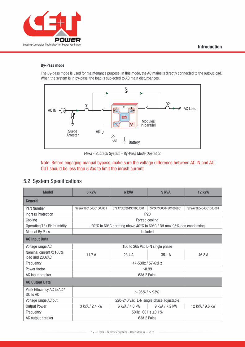
By-Pass mode
The By-pass mode is used for maintenance purpose; in this mode, the AC mains is directly connected to the output load. When the system is in by-pass, the load is subjected to AC main disturbances.
AC INQ1
Q3
S1
Q2AC Load
Surge
Modules
LVD
Battery
Arrester
in parallel
Flexa - Subrack System - By-Pass Mode Operation
Note: Before engaging manual bypass, make sure the voltage difference between AC IN and AC OUT should be less than 5 Vac to limit the inrush current.
5.2 System Specifications
Model 3 kVA 6 kVA 9 kVA 12 kVA
General
Part Number S72A73E0104SC100J001 S72A73E0204SC100J001 S72A73E0304SC100J001 S72A73E0404SC100J001
Ingress Protection IP20Cooling Forced coolingOperating T° / RH humidity -20°C to 60°C derating above 40°C to 60°C / RH max 95% non condensingManual By Pass Included
AC Input Data
Voltage range AC 150 to 265 Vac L-N single phaseNominal current @100% load and 230VAC
11.7 A 23.4 A 35.1 A 46.8 A
Frequency 47-53Hz / 57-63HzPower factor >0.99AC Input breaker 63A 2 Poles
AC Output Data
Peak Efficiency AC to AC / DC to AC
> 96% / > 93%
Voltage range AC out 220-240 Vac L-N single phase adjustableOutput Power 3 kVA / 2.4 kW 6 kVA / 4.8 kW 9 kVA / 7.2 kW 12 kVA / 9.6 kWFrequency 50Hz , 60 Hz ±0.1%AC output breaker 63A 2 Poles
12 – Flexa – Subrack System – User Manual – v1.2
Introduction
13 – Flexa – Subrack System – User Manual – v1.2
Introduction
Model 3 kVA 6 kVA 9 kVA 12 kVA
DC Data (Battery)
Peak Efficiency AC to DC > 93%Nominal voltage (range) 48 Vdc (40 - 60 Vdc)Battery breaker 300A for 1 stringRecharge time for 30 min backup @ 100% load
6 to 8 hours for 80% battery capacity
Signalling & Supervision
Display Synoptic LED on Modules and 2.8” touch screen in Inview S
Supervision Inview S
Communication ETH, SNMP, MODBUS over IPAlarm relay Form C dry contact Major + Minor + 6 relay configurable
System
Dimension: Width x Height x Depth
19 Inch x 5U x 520 mm
System weight without modules
23 kg
Safety & EMC
Safety EN/IEC 62040-1EMC EN/IEC 62040-2Performances EN/IEC62040-3
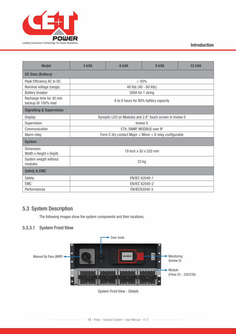
5.3 System DescriptionThe following images show the system components and their locations.
5.3.3.1 System Front View
Door knob
Manual By Pass (MBP) Monitoring(Inview S)
Module(Flexa 25 - 230/230)
System Front View - Details
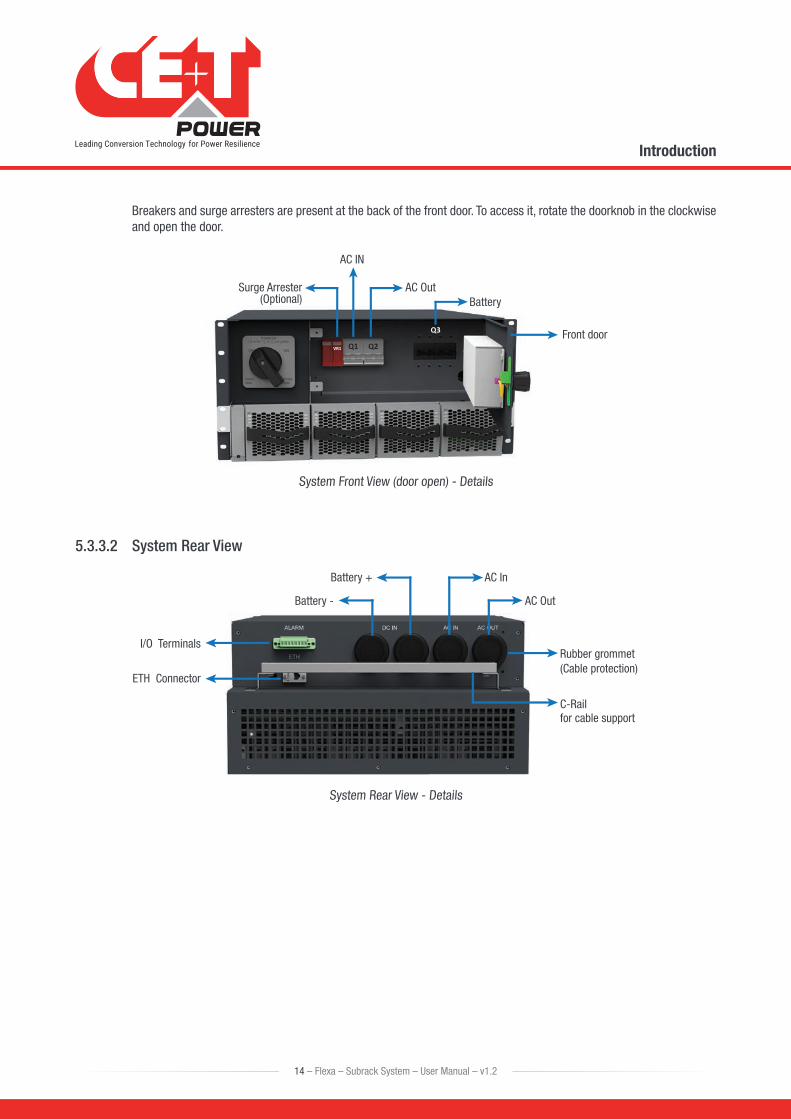
Breakers and surge arresters are present at the back of the front door. To access it, rotate the doorknob in the clockwise and open the door.
Q1VR1 Q2
Q3
AC OutBattery
AC IN
Surge Arrester(Optional)
Front door
System Front View (door open) - Details
5.3.3.2 System Rear View
Battery -
Battery + AC In
AC Out
I/O Terminals
ETH Connector
Rubber grommet (Cable protection)
C-Rail for cable support
System Rear View - Details
14 – Flexa – Subrack System – User Manual – v1.2
Introduction
6. Components
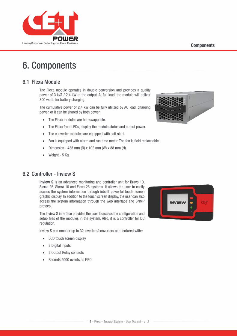
6.1 Flexa ModuleThe Flexa module operates in double conversion and provides a quality power of 3 kVA / 2.4 kW at the output. At full load, the module will deliver 300 watts for battery charging.
The cumulative power of 2.4 kW can be fully utilized by AC load, charging power, or it can be shared by both power.
• The Flexa modules are hot-swappable.
• The Flexa front LEDs, display the module status and output power.
• The converter modules are equipped with soft start.
• Fan is equipped with alarm and run time meter. The fan is field replaceable.
• Dimension - 435 mm (D) x 102 mm (W) x 88 mm (H).
• Weight - 5 Kg.
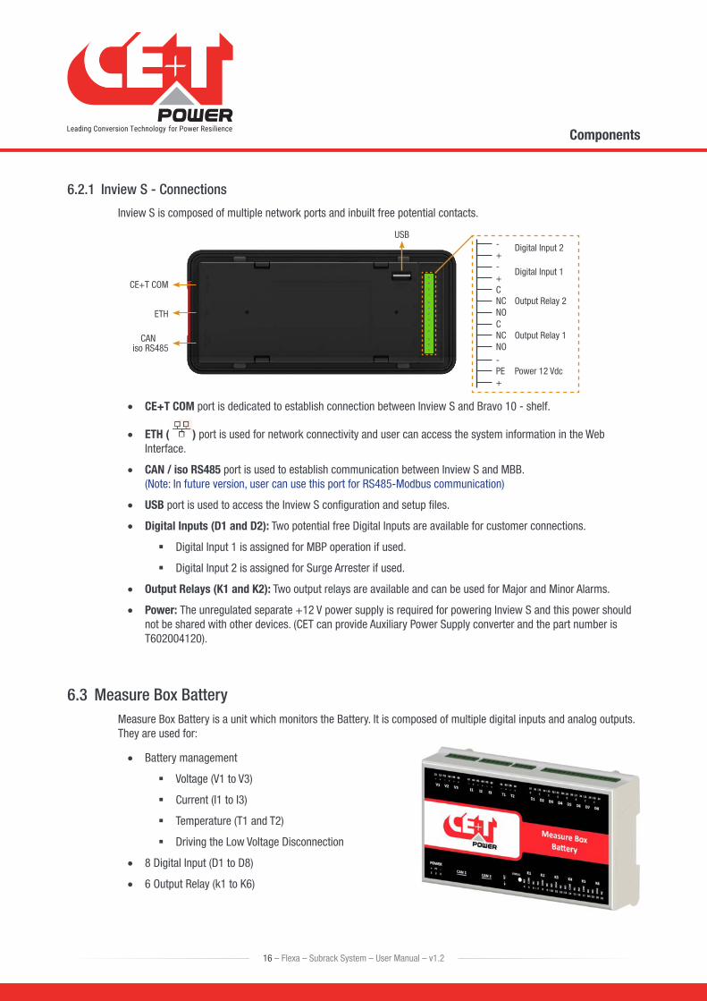
6.2 Controller - Inview SInview S is an advanced monitoring and controller unit for Bravo 10, Sierra 25, Sierra 10 and Flexa 25 systems. It allows the user to easily access the system information through inbuilt powerful touch screen graphic display. In addition to the touch screen display, the user can also access the system information through the web interface and SNMP protocol.
The Inview S interface provides the user to access the configuration and setup files of the modules in the system. Also, it is a controller for DC regulation.
Inview S can monitor up to 32 inverters/converters and featured with::
• LCD touch screen display
• 2 Digital Inputs
• 2 Output Relay contacts
• Records 5000 events as FIFO
15 – Flexa – Subrack System – User Manual – v1.2
Components
6.2.1 Inview S - Connections
Inview S is composed of multiple network ports and inbuilt free potential contacts.
C
-
C
+
-
NC
+Digital Input 2
Digital Input 1
Output Relay 2
Output Relay 1
Power 12 Vdc
NC
PE
NO
-
NO
+
CANiso RS485
ETH
USB
CE+T COM
• CE+T COM port is dedicated to establish connection between Inview S and Bravo 10 - shelf.
• ETH ( ) port is used for network connectivity and user can access the system information in the Web Interface.
• CAN / iso RS485 port is used to establish communication between Inview S and MBB. (Note: In future version, user can use this port for RS485-Modbus communication)
• USB port is used to access the Inview S configuration and setup files.
• Digital Inputs (D1 and D2): Two potential free Digital Inputs are available for customer connections.
� Digital Input 1 is assigned for MBP operation if used.
� Digital Input 2 is assigned for Surge Arrester if used.
• Output Relays (K1 and K2): Two output relays are available and can be used for Major and Minor Alarms.
• Power: The unregulated separate +12 V power supply is required for powering Inview S and this power should not be shared with other devices. (CET can provide Auxiliary Power Supply converter and the part number is T602004120).
6.3 Measure Box BatteryMeasure Box Battery is a unit which monitors the Battery. It is composed of multiple digital inputs and analog outputs. They are used for:
• Battery management
� Voltage (V1 to V3)
� Current (I1 to I3)
� Temperature (T1 and T2)
� Driving the Low Voltage Disconnection
• 8 Digital Input (D1 to D8)
• 6 Output Relay (k1 to K6)
16 – Flexa – Subrack System – User Manual – v1.2
Components
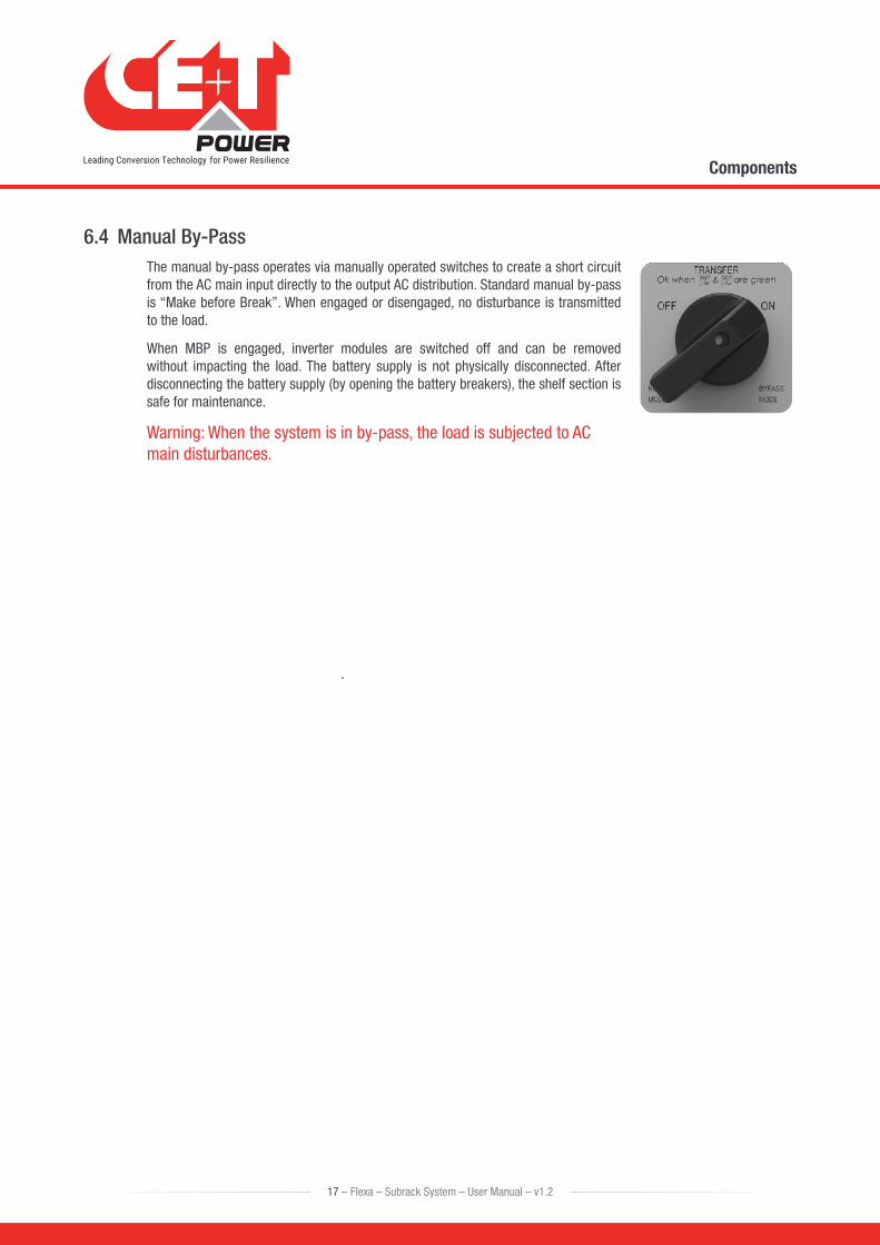
6.4 Manual By-PassThe manual by-pass operates via manually operated switches to create a short circuit from the AC main input directly to the output AC distribution. Standard manual by-pass is “Make before Break”. When engaged or disengaged, no disturbance is transmitted to the load.
When MBP is engaged, inverter modules are switched off and can be removed without impacting the load. The battery supply is not physically disconnected. After disconnecting the battery supply (by opening the battery breakers), the shelf section is safe for maintenance.
Warning: When the system is in by-pass, the load is subjected to AC main disturbances.
17 – Flexa – Subrack System – User Manual – v1.2
Components
7. Installation
7.1 Unpacking the systemModules are packed separately.
The packing material of the ECI system is recyclable.
7.2 Installing the System into a CabinetThis system is designed for 19-inch mounting applications.
• 19” – 600 mm depth cabinets.
• 19” – 800 mm depth cabinets.
Warning: Place the modules in the corresponding slot, only after the proper installation.
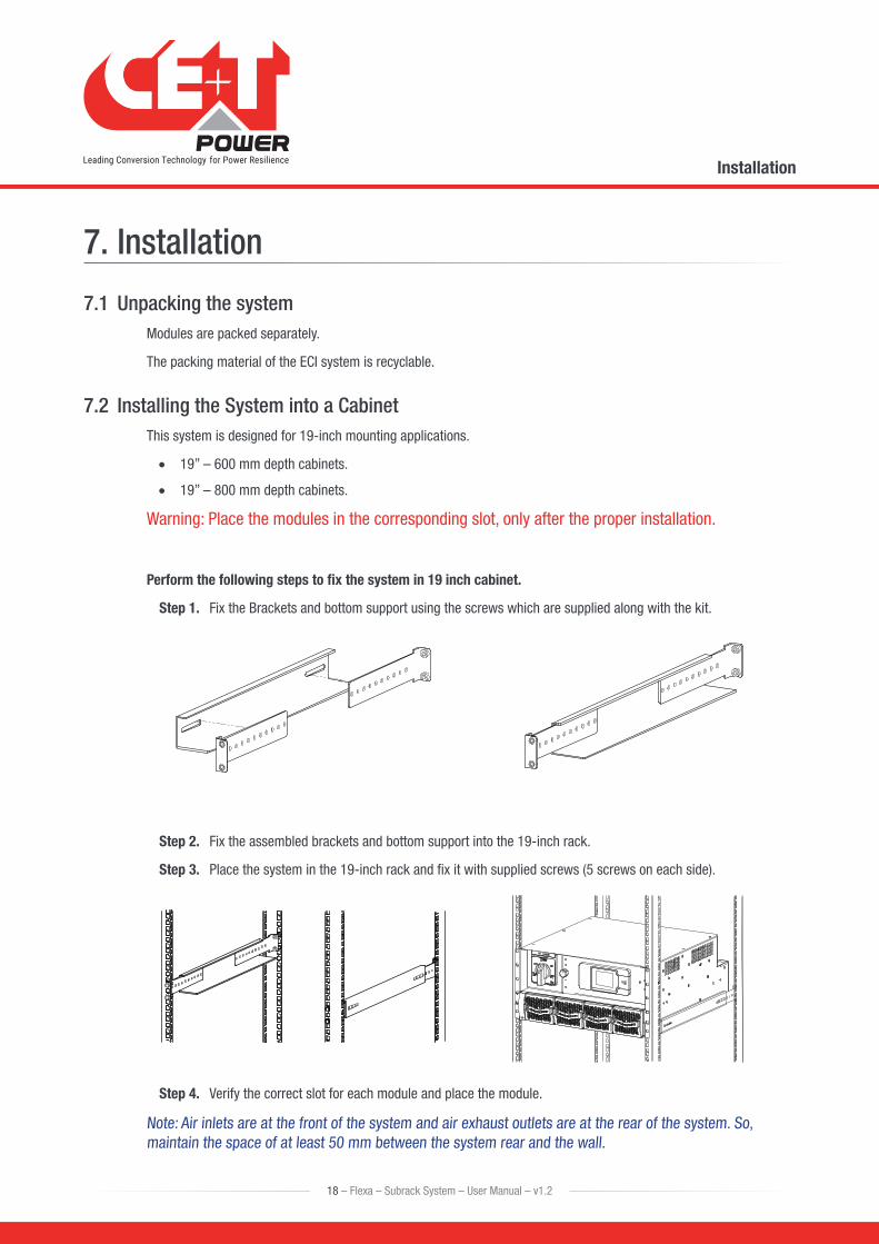
Perform the following steps to fix the system in 19 inch cabinet.
Step 1. Fix the Brackets and bottom support using the screws which are supplied along with the kit.
Step 2. Fix the assembled brackets and bottom support into the 19-inch rack.
Step 3. Place the system in the 19-inch rack and fix it with supplied screws (5 screws on each side).
Step 4. Verify the correct slot for each module and place the module.
Note: Air inlets are at the front of the system and air exhaust outlets are at the rear of the system. So, maintain the space of at least 50 mm between the system rear and the wall.
18 – Flexa – Subrack System – User Manual – v1.2
Installation
7.3 Electrical Installation
7.3.1 Pre-requisites
• The system have markings for all terminations.
• All cables shall be rated at min 90° C.
• Electrical terminations shall be tightened with 5 Nm.
• Battery Connections: Observe Polarity.
• AC Connections: Respect Phases.
• Wire all positions in the system as per markings.
• Input AC / Output AC / Battery / Signal cables shall be separated.
• Cable crossings shall be done at 90° angles.
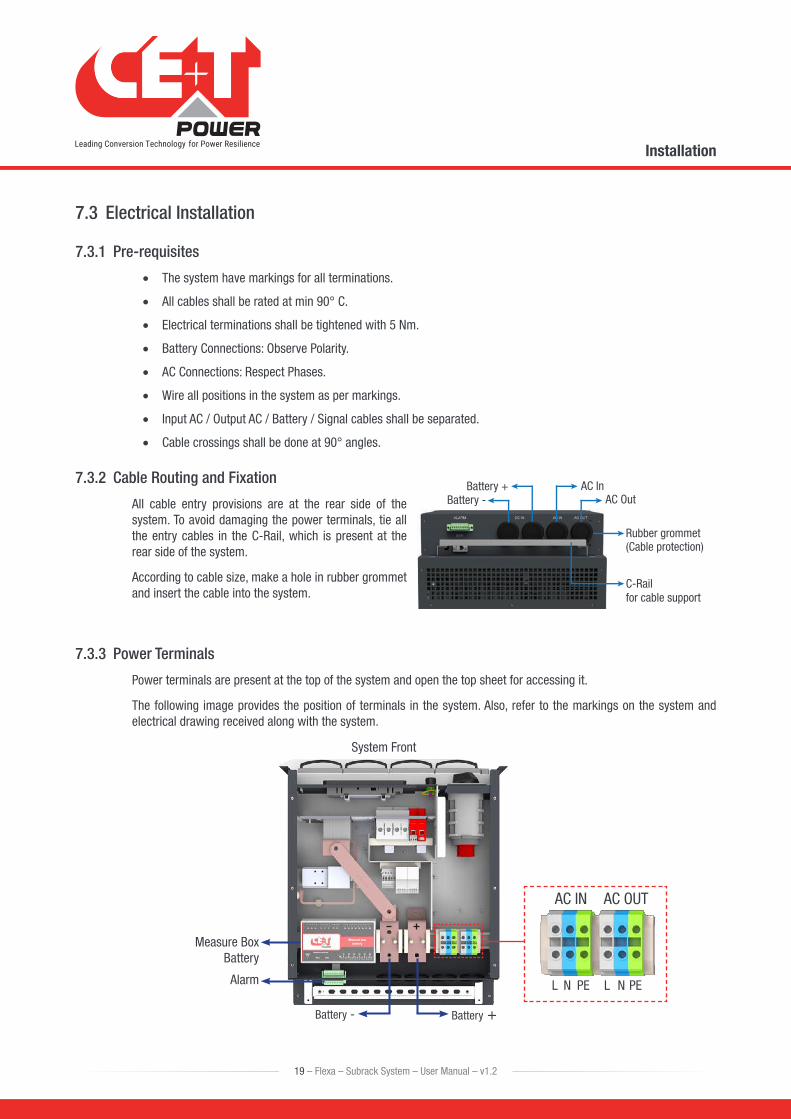
7.3.2 Cable Routing and Fixation
All cable entry provisions are at the rear side of the system. To avoid damaging the power terminals, tie all the entry cables in the C-Rail, which is present at the rear side of the system.
According to cable size, make a hole in rubber grommet and insert the cable into the system.
7.3.3 Power Terminals
Power terminals are present at the top of the system and open the top sheet for accessing it.
The following image provides the position of terminals in the system. Also, refer to the markings on the system and electrical drawing received along with the system.
AC IN
L LN NPE
Battery +
System Front
Battery -
Measure BoxBattery
Alarm PE
AC OUT
Battery -Battery + AC In
AC Out
Rubber grommet (Cable protection)
C-Rail for cable support
19 – Flexa – Subrack System – User Manual – v1.2
Installation
7.3.4 Battery connection
Model Internal ProtectionRecommended
CableLug
Flexa - Subrack4 Pole MCB
300 A95 mm2
Per poleInsulated U type
7.3.5 AC Input connection
Model Internal ProtectionRecommended
CableLug
Flexa - Subrack2 Pole MCB
63 A25 mm2 Insulated Pin type
It is recommended to install appropriate breaker at AC input and place a warning label near the breaker stating message as “ISOLATE UNINTERRUPTIBLE POWER SUPPLY (UPS) BEFORE WORKING ON THIS CIRCUIT”.
7.3.6 AC Output connection
Model Internal ProtectionRecommended
CableLug
Flexa - Subrack2 Pole MCB
63 A25 mm2 Insulated Pin type
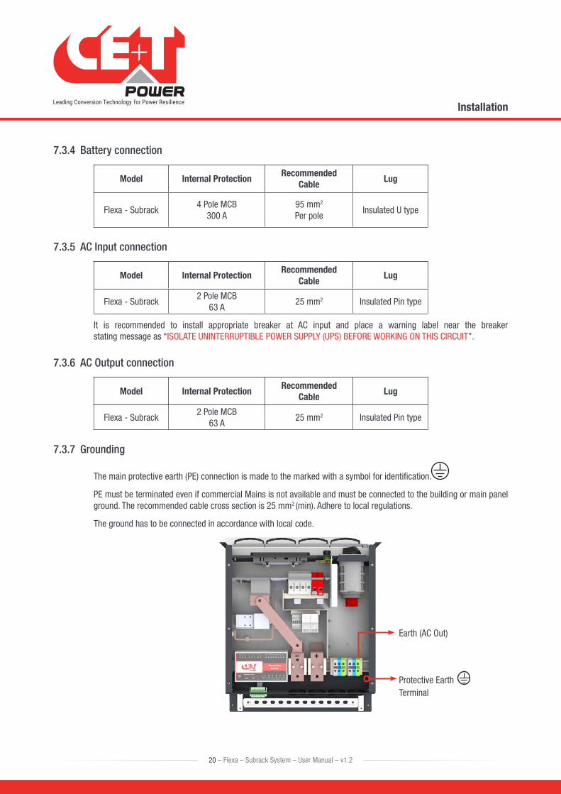
7.3.7 Grounding
The main protective earth (PE) connection is made to the marked with a symbol for identification.
PE must be terminated even if commercial Mains is not available and must be connected to the building or main panel ground. The recommended cable cross section is 25 mm2 (min). Adhere to local regulations.
The ground has to be connected in accordance with local code.
Protective EarthTerminal
Earth (AC Out)
20 – Flexa – Subrack System – User Manual – v1.2
Installation
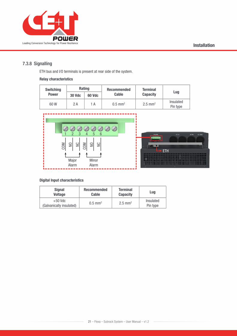
7.3.8 Signalling
ETH bus and I/O terminals is present at rear side of the system.
Relay characteristics
Switching Power
Rating Recommended Cable
Terminal Capacity
Lug30 Vdc 60 Vdc
60 W 2 A 1 A 0.5 mm2 2.5 mm2 Insulated Pin type
1
COM NO NC
COM NO NC
42
Major Alarm
Minor Alarm
53 6
ETH
Digital Input characteristics
Signal Voltage
Recommended Cable
Terminal Capacity
Lug
+50 Vdc (Galvanically insulated)
0.5 mm2 2.5 mm2 Insulated Pin type
21 – Flexa – Subrack System – User Manual – v1.2
Installation
8. Operation
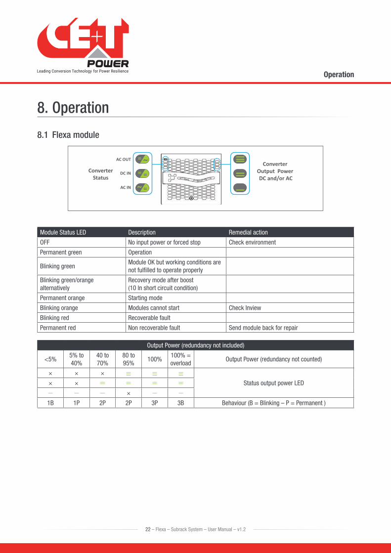
8.1 Flexa module
= ~= =
~ =
AC OUT
DC IN
AC IN
ConverterStatus
Converter Output Power DC and/or AC
Module Status LED Description Remedial action
OFF No input power or forced stop Check environment
Permanent green Operation
Blinking greenModule OK but working conditions are not fulfilled to operate properly
Blinking green/orange alternatively
Recovery mode after boost (10 In short circuit condition)
Permanent orange Starting mode
Blinking orange Modules cannot start Check Inview
Blinking red Recoverable fault
Permanent red Non recoverable fault Send module back for repair
Output Power (redundancy not included)
<5%5% to 40%
40 to 70%
80 to 95%
100%100% = overload
Output Power (redundancy not counted)
× × ×
Status output power LED× ×
×
1B 1P 2P 2P 3P 3B Behaviour (B = Blinking – P = Permanent )
22 – Flexa – Subrack System – User Manual – v1.2
Operation
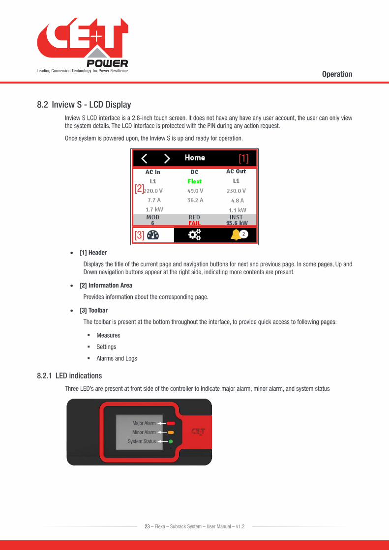
8.2 Inview S - LCD DisplayInview S LCD interface is a 2.8-inch touch screen. It does not have any have any user account, the user can only view the system details. The LCD interface is protected with the PIN during any action request.
Once system is powered upon, the Inview S is up and ready for operation.
[1]
[2]
[3]
• [1] Header
Displays the title of the current page and navigation buttons for next and previous page. In some pages, Up and Down navigation buttons appear at the right side, indicating more contents are present.
• [2] Information Area
Provides information about the corresponding page.
• [3] Toolbar
The toolbar is present at the bottom throughout the interface, to provide quick access to following pages:
� Measures
� Settings
� Alarms and Logs
8.2.1 LED indications
Three LED’s are present at front side of the controller to indicate major alarm, minor alarm, and system status
Major Alarm
Minor Alarm
System Status
23 – Flexa – Subrack System – User Manual – v1.2
Operation
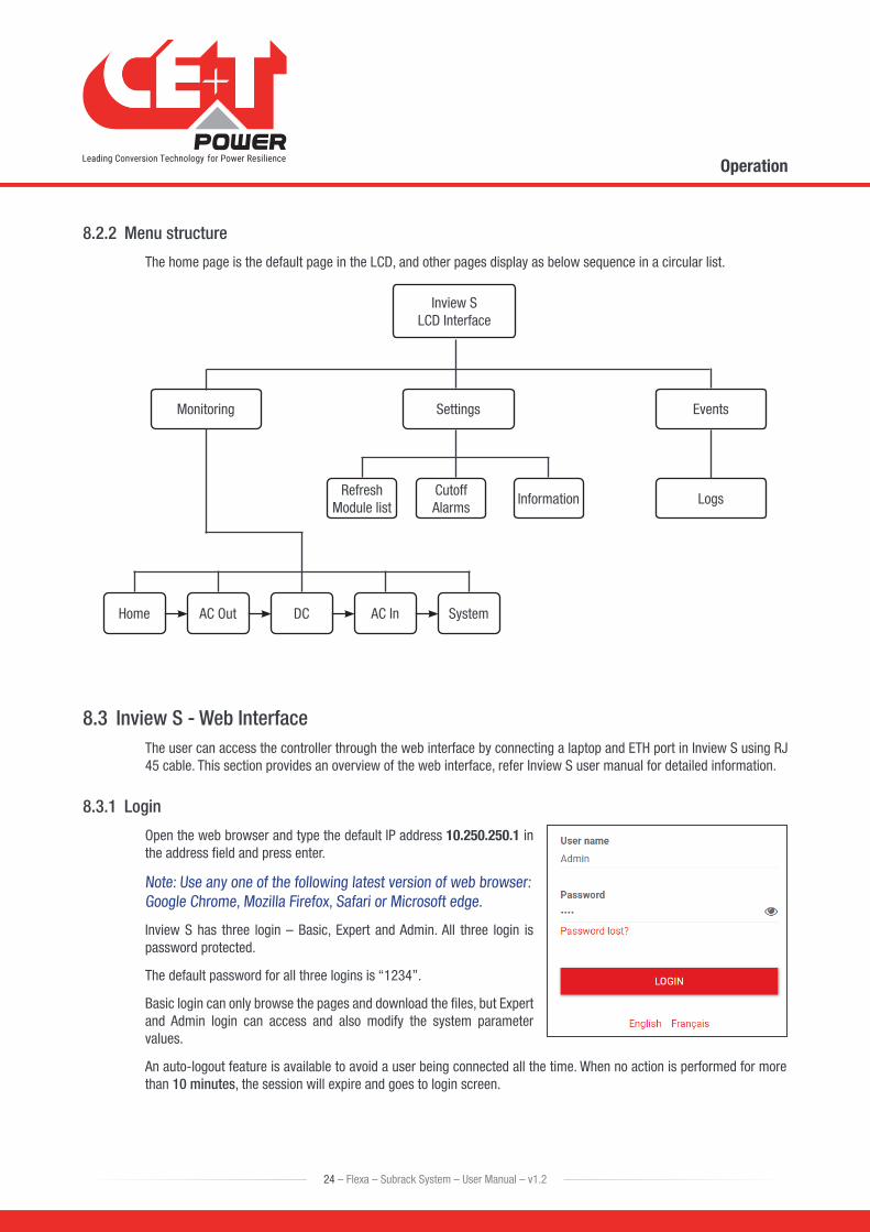
8.2.2 Menu structure
The home page is the default page in the LCD, and other pages display as below sequence in a circular list.
AC InHome SystemAC Out DC
Inview S LCD Interface
Monitoring Settings Events
LogsRefresh
Module listCutoff Alarms
Information
8.3 Inview S - Web InterfaceThe user can access the controller through the web interface by connecting a laptop and ETH port in Inview S using RJ 45 cable. This section provides an overview of the web interface, refer Inview S user manual for detailed information.
8.3.1 Login
Open the web browser and type the default IP address 10.250.250.1 in the address field and press enter.
Note: Use any one of the following latest version of web browser: Google Chrome, Mozilla Firefox, Safari or Microsoft edge.
Inview S has three login – Basic, Expert and Admin. All three login is password protected.
The default password for all three logins is “1234”.
Basic login can only browse the pages and download the files, but Expert and Admin login can access and also modify the system parameter values.
An auto-logout feature is available to avoid a user being connected all the time. When no action is performed for more than 10 minutes, the session will expire and goes to login screen.
24 – Flexa – Subrack System – User Manual – v1.2
Operation
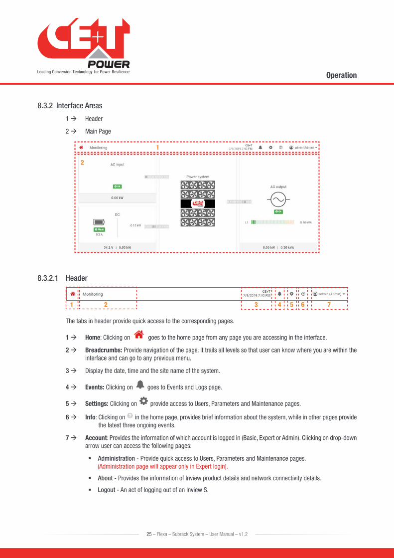
8.3.2 Interface Areas
1 Header
2 Main Page
1
2
8.3.2.1 Header
1 2 3 4 5 6 7
The tabs in header provide quick access to the corresponding pages.
1 Home: Clicking on goes to the home page from any page you are accessing in the interface.
2 Breadcrumbs: Provide navigation of the page. It trails all levels so that user can know where you are within the interface and can go to any previous menu.
3 Display the date, time and the site name of the system.
4 Events: Clicking on goes to Events and Logs page.
5 Settings: Clicking on provide access to Users, Parameters and Maintenance pages.
6 Info: Clicking on in the home page, provides brief information about the system, while in other pages provide the latest three ongoing events.
7 Account: Provides the information of which account is logged in (Basic, Expert or Admin). Clicking on drop-down arrow user can access the following pages:
� Administration - Provide quick access to Users, Parameters and Maintenance pages. (Administration page will appear only in Expert login).
� About - Provides the information of Inview product details and network connectivity details.
� Logout - An act of logging out of an Inview S.
25 – Flexa – Subrack System – User Manual – v1.2
Operation
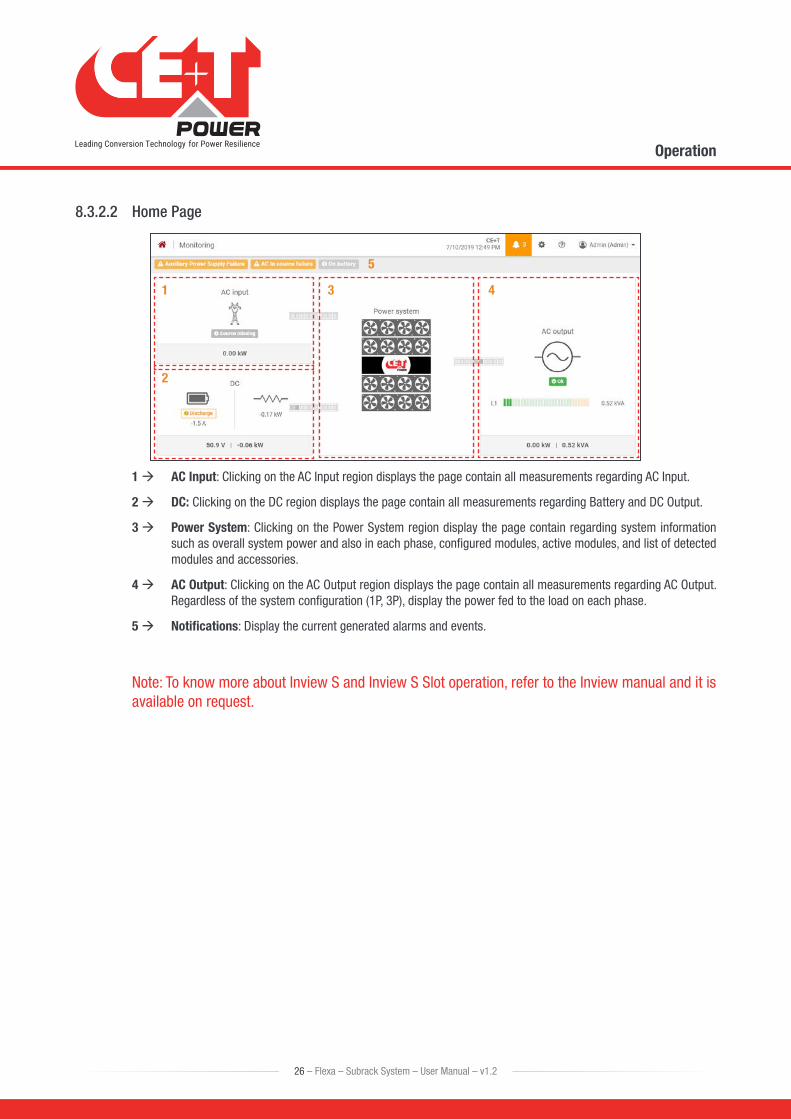
8.3.2.2 Home Page
1
2
3 4
5
1 AC Input: Clicking on the AC Input region displays the page contain all measurements regarding AC Input.
2 DC: Clicking on the DC region displays the page contain all measurements regarding Battery and DC Output.
3 Power System: Clicking on the Power System region display the page contain regarding system information such as overall system power and also in each phase, configured modules, active modules, and list of detected modules and accessories.
4 AC Output: Clicking on the AC Output region displays the page contain all measurements regarding AC Output. Regardless of the system configuration (1P, 3P), display the power fed to the load on each phase.
5 Notifications: Display the current generated alarms and events.
Note: To know more about Inview S and Inview S Slot operation, refer to the Inview manual and it is available on request.
26 – Flexa – Subrack System – User Manual – v1.2
Operation
9. System Start-up
9.1 Installation Check • Make sure that the system is properly mounted in the cabinet/floor in accordance to section 7.2, page 18 and
electrical connections are made accordance to section 7.3, page 19.
• Check AC wiring connection and battery polarity.
• Make sure that the earth is connected to system.
• Make sure that all AC Input and Battery breakers are switched OFF.
• Make sure that all cables comply with recommendations and local regulations.
• Make sure that all cables are strain relieved.
• Make sure that all external breakers are complied with recommendations and local regulations.
• Re-tighten all electrical terminations.
• Empty module positions shall be covered with dummy cover.
9.2 Start-up
1. AC Input
a) Insert only one module at first slot (left) in the system. (Before inserting any module into the system, make sure nothing is blocking the module such as objects and wires.)
b) Switch ON the AC power supply (Q1).
c) Inview S monitor start (~30s).
d) Module LED’s starts with fixed orange, then DC IN and AC IN LED’s will turn green. Finally, AC OUT LED will turn green.
2. Configure the system through Inview S
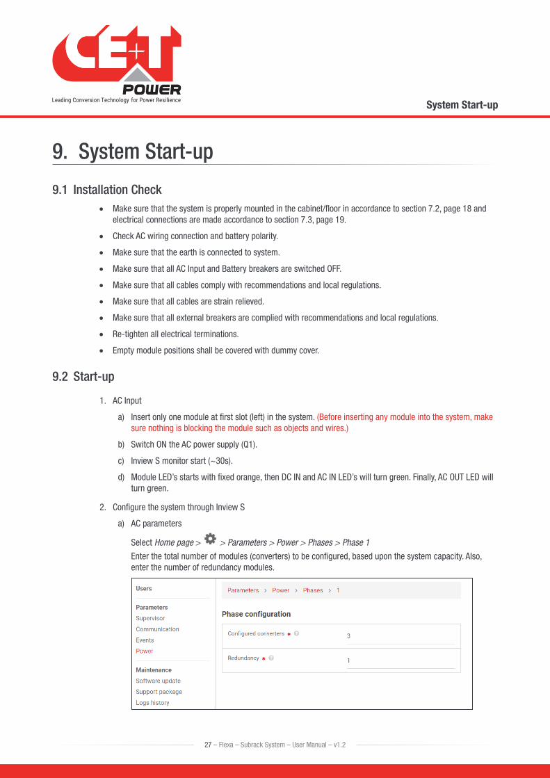
a) AC parameters
Select Home page > > Parameters > Power > Phases > Phase 1
Enter the total number of modules (converters) to be configured, based upon the system capacity. Also, enter the number of redundancy modules.
27 – Flexa – Subrack System – User Manual – v1.2
System Start-up
Note: Before engaging manual bypass, adjust the voltage of AC OUT with AC IN and the difference between two voltages should be less than 5 Vac to limit the inrush current.
To adjust the AC Out voltage, go to Home page > > Parameters > Power > Converters(modules) and modify the “Parameter 26”.
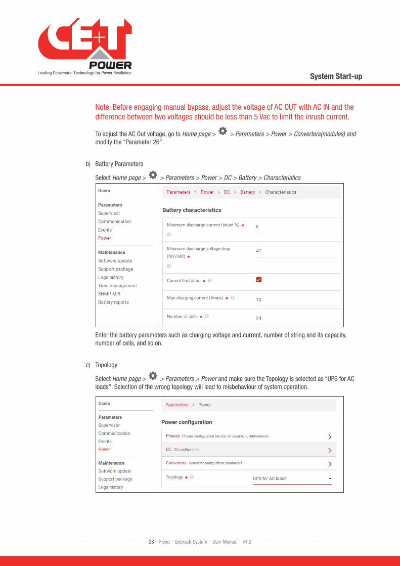
b) Battery Parameters
Select Home page > > Parameters > Power > DC > Battery > Characteristics
Enter the battery parameters such as charging voltage and current, number of string and its capacity, number of cells, and so on.
c) Topology
Select Home page > > Parameters > Power and make sure the Topology is selected as “UPS for AC loads”. Selection of the wrong topology will lead to misbehaviour of system operation.
28 – Flexa – Subrack System – User Manual – v1.2
System Start-up
d) Set the date and time.
Select Home page > > Parameters > Supervisor > Time
Note: To know more about configuration and parameters setting, refer Inview S user manual.
3. Battery Start up
a) Switch ON the Battery (Q3).
b) Inview S read the battery voltage from Measure Box Battery and also check the voltage through multimeter.
c) The system charges the battery (if it is not fully charged).
4. Insert remaining modules, one by one, in to the system.
a) Wait until all the modules status LED’s (left) turns GREEN.
b) Switch ON AC output breakers Q2.
c) System supply power to the load.
5. Save and clear the log file.
6. Download the configuration file and save it for future reference.
29 – Flexa – Subrack System – User Manual – v1.2
System Start-up
10. Replacement procedures
10.1 Flexa module • The Flexa module is hot swappable.
• When a new module is inserted in a live system it automatically takes the working set of parameters.
• When a new module is inserted in a live system it is automatically assigned to the next available address.
10.1.1 Removal
Notice: When one or several converter modules is/are removed access to live parts becomes possible. Replace module(s) with dummy cover without delay.
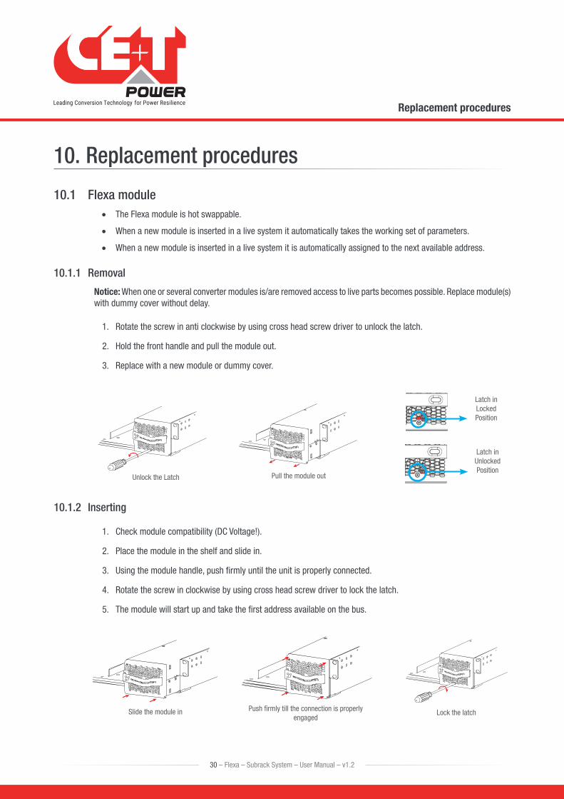
1. Rotate the screw in anti clockwise by using cross head screw driver to unlock the latch.
2. Hold the front handle and pull the module out.
3. Replace with a new module or dummy cover.
Unlock the Latch Pull the module out
Latch in Locked Position
Latch in Unlocked Position
10.1.2 Inserting
1. Check module compatibility (DC Voltage!).
2. Place the module in the shelf and slide in.
3. Using the module handle, push firmly until the unit is properly connected.
4. Rotate the screw in clockwise by using cross head screw driver to lock the latch.
5. The module will start up and take the first address available on the bus.
Push firmly till the connection is properly engaged
Lock the latchSlide the module in
30 – Flexa – Subrack System – User Manual – v1.2
Replacement procedures
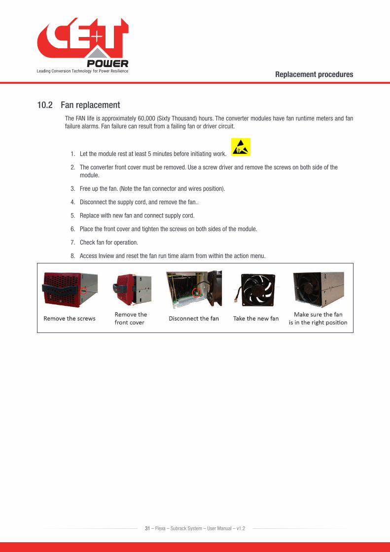
10.2 Fan replacementThe FAN life is approximately 60,000 (Sixty Thousand) hours. The converter modules have fan runtime meters and fan failure alarms. Fan failure can result from a failing fan or driver circuit.
1. Let the module rest at least 5 minutes before initiating work.
2. The converter front cover must be removed. Use a screw driver and remove the screws on both side of the module.
3. Free up the fan. (Note the fan connector and wires position).
4. Disconnect the supply cord, and remove the fan..
5. Replace with new fan and connect supply cord.
6. Place the front cover and tighten the screws on both sides of the module.
7. Check fan for operation.
8. Access Inview and reset the fan run time alarm from within the action menu.
31 – Flexa – Subrack System – User Manual – v1.2
Replacement procedures
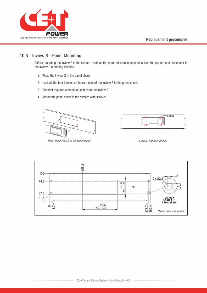
10.3 Inview S - Panel MountingBefore mounting the Inview S in the system, route all the required connection cables from the system and place near to the Inview S mounting location.
1. Place the Inview S in the panel sheet.
2. Lock all the four latches at the rear side of the Inview S in the panel sheet.
3. Connect required connection cables to the Inview S.
4. Mount the panel sheet in the system with screws.
Place the Inview S in the panel sheet Lock it with four latches
Latch
Dimensions are in mm
32 – Flexa – Subrack System – User Manual – v1.2
Replacement procedures
11. Manual By-Pass OperationManual By-Pass has to be operated by trained people only.
When the system is in manual by-pass, the load is subjected to mains AC voltage without active filtering.
An MBP Engaged output alarm will occur when the system is in the manual by-pass.
The Manual By-Pass is not possible to operate remotely.
11.1 Pre requisitesBefore engaging MBP, the following conditions have to be fulfilled and actively checked.
• Commercial AC must be present.
• Adjust the voltage of AC OUT with AC IN and the difference between two voltages should be less than 5 Vac.
• Module must be synchronized with commercial power.
• The upstream AC & Battery breaker must be correctly sized to accept possible overload, The inverter might be overloaded during MBP procedure, depending on voltage network and output inverter voltage setting and if the AC is supplied by a Gen-set, the minimal required power will be twice nominal power of the inverter.
11.2 Manual By-Pass OperationThe manual By-Pass operates via individual switch that creates a by-pass from mains input via output AC distribution. Inverter modules are by-passed and possible to disconnect without impacting the load.
Operation is “Make before Break”.
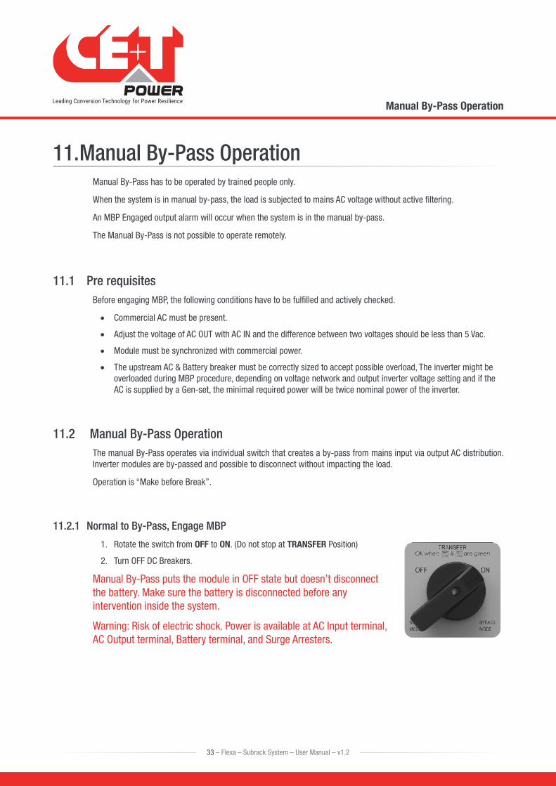
11.2.1 Normal to By-Pass, Engage MBP
1. Rotate the switch from OFF to ON. (Do not stop at TRANSFER Position)
2. Turn OFF DC Breakers.
Manual By-Pass puts the module in OFF state but doesn’t disconnect the battery. Make sure the battery is disconnected before any intervention inside the system.
Warning: Risk of electric shock. Power is available at AC Input terminal, AC Output terminal, Battery terminal, and Surge Arresters.
33 – Flexa – Subrack System – User Manual – v1.2
Manual By-Pass Operation
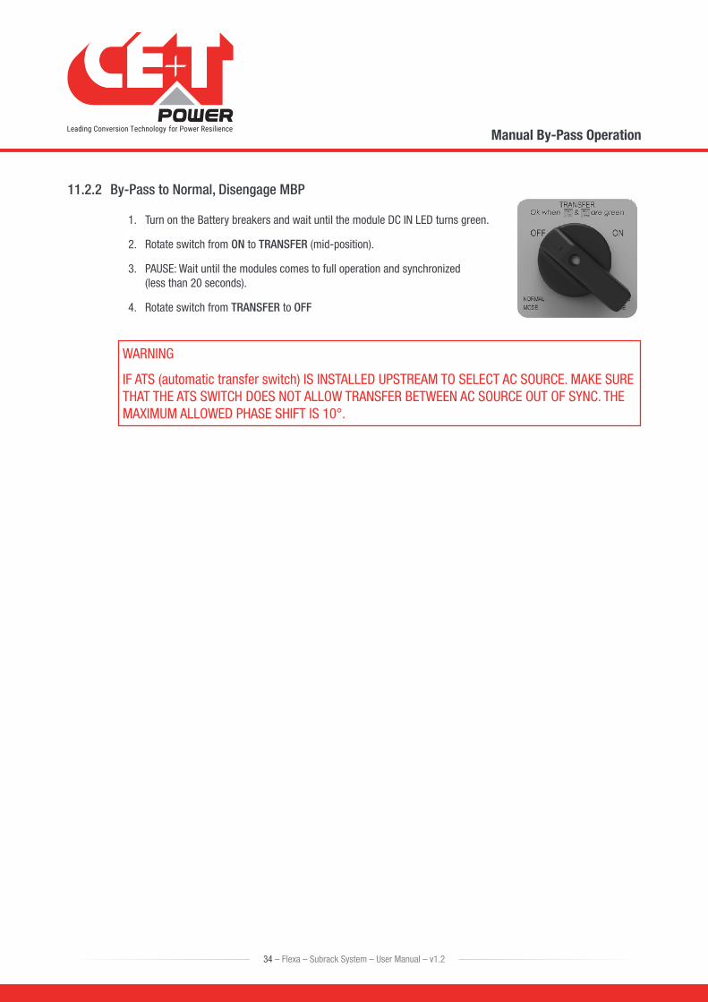
11.2.2 By-Pass to Normal, Disengage MBP
1. Turn on the Battery breakers and wait until the module DC IN LED turns green.
2. Rotate switch from ON to TRANSFER (mid-position).
3. PAUSE: Wait until the modules comes to full operation and synchronized (less than 20 seconds).
4. Rotate switch from TRANSFER to OFF
WARNING
IF ATS (automatic transfer switch) IS INSTALLED UPSTREAM TO SELECT AC SOURCE. MAKE SURE THAT THE ATS SWITCH DOES NOT ALLOW TRANSFER BETWEEN AC SOURCE OUT OF SYNC. THE MAXIMUM ALLOWED PHASE SHIFT IS 10°.
34 – Flexa – Subrack System – User Manual – v1.2
Manual By-Pass Operation
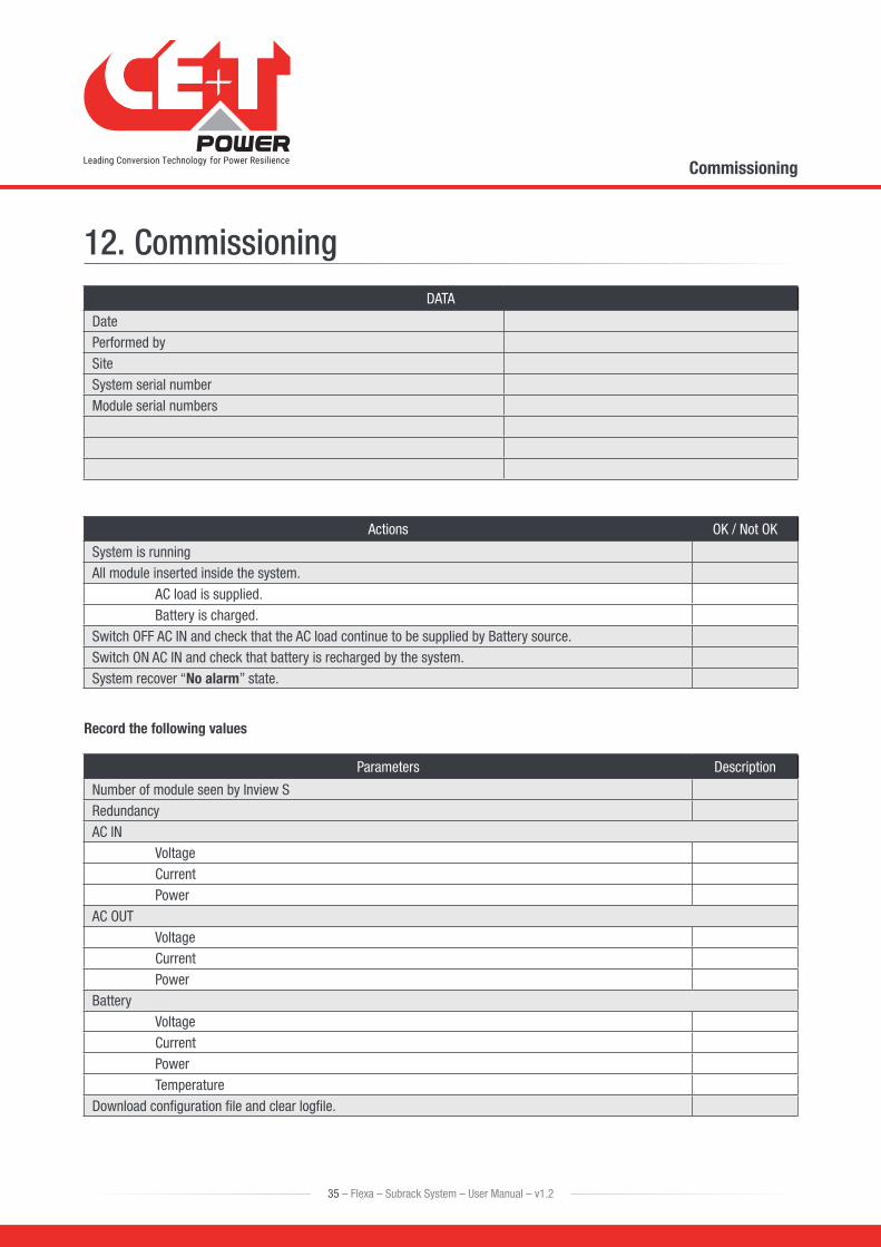
12. CommissioningDATA
DatePerformed bySiteSystem serial numberModule serial numbers
Actions OK / Not OK
System is runningAll module inserted inside the system.
AC load is supplied.Battery is charged.
Switch OFF AC IN and check that the AC load continue to be supplied by Battery source.Switch ON AC IN and check that battery is recharged by the system.System recover “No alarm” state.
Record the following values
Parameters Description
Number of module seen by Inview SRedundancyAC IN
Voltage CurrentPower
AC OUTVoltageCurrentPower
BatteryVoltageCurrentPowerTemperature
Download configuration file and clear logfile.
35 – Flexa – Subrack System – User Manual – v1.2
Commissioning
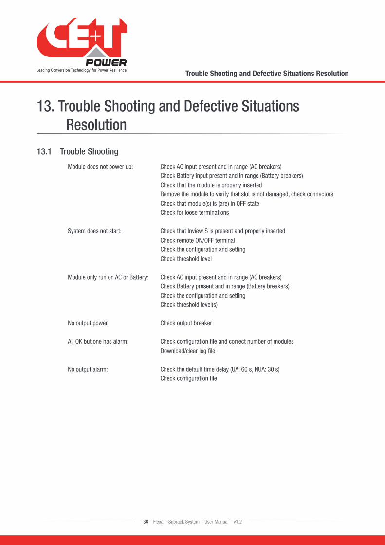
13. Trouble Shooting and Defective Situations Resolution
13.1 Trouble Shooting
Module does not power up: Check AC input present and in range (AC breakers)Check Battery input present and in range (Battery breakers) Check that the module is properly inserted Remove the module to verify that slot is not damaged, check connectorsCheck that module(s) is (are) in OFF stateCheck for loose terminations
System does not start: Check that Inview S is present and properly insertedCheck remote ON/OFF terminalCheck the configuration and setting Check threshold level
Module only run on AC or Battery: Check AC input present and in range (AC breakers)Check Battery present and in range (Battery breakers) Check the configuration and settingCheck threshold level(s)
No output power Check output breaker
All OK but one has alarm: Check configuration file and correct number of modulesDownload/clear log file
No output alarm: Check the default time delay (UA: 60 s, NUA: 30 s)Check configuration file
36 – Flexa – Subrack System – User Manual – v1.2
Trouble Shooting and Defective Situations Resolution
14. ServiceFor Service
• Check Service Level Agreement (SLA) of your vendor. Most of the time they provide assistance on call with integrated service. If such SLA is in place, you must call their assistance first.
• If your vendor doesn’t provide such assistance (*) you may contact CE+T through email: [email protected]
(*) CE+T will redirect your call to your vendor if he has such SLA in place.
37 – Flexa – Subrack System – User Manual – v1.2
Service
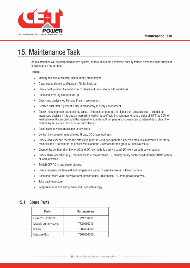
15. Maintenance TaskAs maintenance will be performed on live system, all task should be performed only by trained personnel with sufficient knowledge on ECI product.
Tasks:
• Identify the site, customer, rack number, product type.
• Download and save configuration file for back up.
• Check configuration file to be in accordance with operational site conditions.
• Read and save log file for back up.
• Check and analyse log file, and if alarm are present.
• Replace dust filter if present. Filter is mandatory in dusty environment.
• Check module temperature and log value. If internal temperature is higher then previous year, it should be interesting analyse if it is due an increasing load or dust effect. It is common to have a delta of 15°C by 30% of load between the ambient and the internal temperature. If temperature increase due to internal dust, clean the module by air suction blower or vacuum cleaner.
• Clean cabinet (vacuum cleaner or dry cloth).
• Control the converter mapping (AC Group, DC Group, Address).
• Check load level and record the rate value (print in word document the 4 screen modules information for the 32 modules, the 3 screen for the phases value and the 2 screens for the group AC and DC value).
• Change the configuration file for AC and DC mix mode to check that all ECI work on both power supply.
• Check alarm operation (e.g., redundancy lost, mains failure, DC failure) on dry contact and through SNMP system or web interface.
• Switch OFF AC IN and check alarms.
• Check temperature terminal and temperature wiring. If possible use an infrared camera.
• Read and record value as wave form, power factor, Crest factor, THD from power analyzer.
• Take cabinet picture.
• Keep track of report and provide end user with a copy.
15.1 Spare Parts
Parts Part numbers
Flexa 25 - 230/230 T721730211
Module dummy cover T721030010
Inview S T302004100
Measure Box T302006000
38 – Flexa – Subrack System – User Manual – v1.2
Maintenance Task
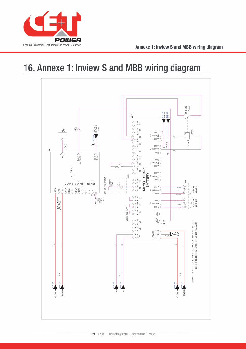
16. Annexe 1: Inview S and MBB wiring diagram
T1BAT
TER
YTE
MP
-+
-+
-+
-+
-+
-+
-+
-+
CA
N1
CAN
2
CC
CC
CC
CC
ME
AS
UR
EB
OX
BA
TTE
RY
12
34
56
78
910
1112
1314
1516
1718
1920
21
NO
COM
NC
NO
COM
NC
NO
COM
NC
NO
COM
NC
NO
COM
NC
NO
COM
NC
+P
E-
K1
K2
K3
K4
K5
K6
5352
5150
4947
4645
4448
4140
3942
3736
3534
3332
3130
2928
2726
2524
2322
3843
D5
I1D
7D
6V
2V
1V
3I2
I3T1
T2D
1D
2D
3D
4D
8
PO
WE
R
(0,5)
OU
TO
FTH
ES
YSTE
M
+12V
aux
0Vau
x
+12V
aux
0Vau
x
A3
(0,5
)
(0,5
)
A
X8
LAN
(0,5
)A
(0,5
)
V1+ V1-
19 2353 54 53 54
(0.5
Blk
)
(0.5
Blk
)
36
MA
JOR
ALA
RM
MIN
OR
ALA
RM
PINK
GREY
YELLOW
WHITE
REM
ARK
S:
X9
2-3
CLO
SE
INC
AS
EO
FM
AJO
RAL
ARM
X9
5-6
CLO
SE
INC
ASE
OF
MIN
OR
ALAR
M3
X9
71
72VR1
76
77
4
3
S1
74 75
AU
X3
1718
11
K1-
LVD
AU
X
79
78 + -
K1-
LVD
BLA
CK
RE
D
19
12
GREEN
45
BROWN
VBAT
-F
VB
AT+
80
8 8
INV
IEW
A2
DIGIN1-2
RELAY1
RELAY2
CAN
/is
oR
S48
5
CE
+TC
OM
LAN
12V
0VPE
NO
NC C NO
NC C + - -+
14
(NO
SHU
NT)
1FR
OM
EC
IRAC
KX
109
002-
20
003-
07
003-
09
003-
10
003-
11
002-
29
002-
31
F00
1-17
F00
1-28
F00
1-24
003-
04
002-
31
39 – Flexa – Subrack System – User Manual – v1.2
Annexe 1: Inview S and MBB wiring diagram