Flex-Line - ruegg-cheminee.com · Flex-Line User manual 5 2. Editorial The fire is part of the...
36
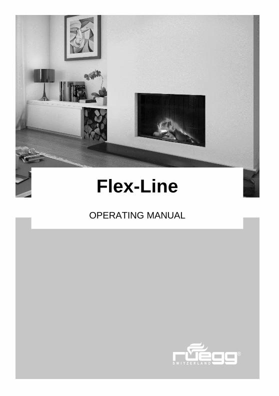
Flex-Line OPERATING MANUAL
Transcript of Flex-Line - ruegg-cheminee.com · Flex-Line User manual 5 2. Editorial The fire is part of the...
Flex-Line User manual
1
Flex-Line
OPERATING MANUAL

Flex-Line User manual
2
Flex-Line User manual
3
1. Table of contents
1. Table of contents ............................................................................................................................3
2. Editorial ..........................................................................................................................................5
2.1. Purpose of the manual ...........................................................................................................6
2.2. Keeping the manual ...............................................................................................................6
2.3. Other applicable documents ..................................................................................................6
2.4. Safety information ..................................................................................................................6
3. Information about the product .........................................................................................................8
3.1. Type test ................................................................................................................................8
3.2. Requirements for installation and operation ...........................................................................8
3.3. Intended use ..........................................................................................................................8
3.4. Temporary-burning fireplace ..................................................................................................8
3.5. Instruction by a specialist installer ..........................................................................................8
3.6. Multiple use of the flue gas system ........................................................................................9
3.7. Technical data .......................................................................................................................9
3.8. Firebox lining with Thermobrikk® ......................................................................................... 11
3.9. Type plate ............................................................................................................................ 12
3.10. Operating elements ............................................................................................................. 13
3.11. Fire door .............................................................................................................................. 14
3.12. Air regulator ......................................................................................................................... 15
3.13. Flue gas valve ..................................................................................................................... 15
3.14. Valves for combustion air/convection air .............................................................................. 16
3.15. Air grille ............................................................................................................................... 16
3.16. Fan ...................................................................................................................................... 17
4. Information about safety ............................................................................................................... 18
4.1. Safety spacing in the heat-radiation area ............................................................................. 18
4.2. Air grille ............................................................................................................................... 18
4.3. Precoat ................................................................................................................................ 18
4.4. Fire door .............................................................................................................................. 19
4.5. Combustion air..................................................................................................................... 19
4.6. Responsibility to inspect ...................................................................................................... 19
4.7. Damage to the system ......................................................................................................... 19
4.8. Changes to the system ........................................................................................................ 19

Flex-Line User manual
4
4.9. Care and maintenance ......................................................................................................... 19
4.10. Chimney fire ........................................................................................................................ 20
5. Fuel .............................................................................................................................................. 21
5.1. Forbidden fuels .................................................................................................................... 21
5.2. Flammable and explosive materials ..................................................................................... 21
5.3. Firewood sizes ..................................................................................................................... 21
6. Information about operation .......................................................................................................... 22
7. Commissioning ............................................................................................................................. 23
7.1. Complete combustion .......................................................................................................... 23
7.2. Reduce harmful substances ................................................................................................. 24
7.3. Firing module ....................................................................................................................... 24
7.4. Putting on wood ................................................................................................................... 25
7.5. Effect of weathering ............................................................................................................. 25
7.6. Preparing the system ........................................................................................................... 26
7.7. Fire ...................................................................................................................................... 26
7.8. Loading in fuel ..................................................................................................................... 26
7.9. Firing with full load ............................................................................................................... 27
7.10. Firing with a light load .......................................................................................................... 27
8. Closing down ................................................................................................................................ 28
8.1. Malfunctions ........................................................................................................................ 28
9. Information about care and maintenance ...................................................................................... 30
9.1. Cleaning .............................................................................................................................. 31
9.2. Checks ................................................................................................................................ 33
9.3. Maintenance ........................................................................................................................ 33
9.4. Repair .................................................................................................................................. 34
9.5. Spare parts .......................................................................................................................... 34
9.6. Warranty conditions ............................................................................................................. 34
Flex-Line User manual
5
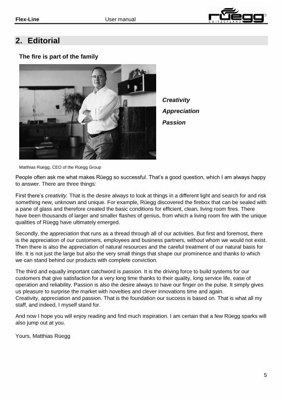
2. Editorial
The fire is part of the family
Creativity
Appreciation
Passion
Matthias Rüegg, CEO of the Rüegg Group
People often ask me what makes Rüegg so successful. That’s a good question, which I am always happy
to answer. There are three things:
First there’s creativity. That is the desire always to look at things in a different light and search for and risk
something new, unknown and unique. For example, Rüegg discovered the firebox that can be sealed with
a pane of glass and therefore created the basic conditions for efficient, clean, living room fires. There
have been thousands of larger and smaller flashes of genius, from which a living room fire with the unique
qualities of Rüegg have ultimately emerged.
Secondly, the appreciation that runs as a thread through all of our activities. But first and foremost, there
is the appreciation of our customers, employees and business partners, without whom we would not exist.
Then there is also the appreciation of natural resources and the careful treatment of our natural basis for
life. It is not just the large but also the very small things that shape our prominence and thanks to which
we can stand behind our products with complete conviction.
The third and equally important catchword is passion. It is the driving force to build systems for our
customers that give satisfaction for a very long time thanks to their quality, long service life, ease of
operation and reliability. Passion is also the desire always to have our finger on the pulse. It simply gives
us pleasure to surprise the market with novelties and clever innovations time and again.
Creativity, appreciation and passion. That is the foundation our success is based on. That is what all my
staff, and indeed, I myself stand for.
And now I hope you will enjoy reading and find much inspiration. I am certain that a few Rüegg sparks will
also jump out at you.
Yours, Matthias Rüegg

Flex-Line User manual
6
2.1. Purpose of the manual This manual is aimed at operators of a fireplace. It contains important information for safe and sustainable
operation, as well as for the care and maintenance of your fireplace.
Read this manual through carefully before starting the first fire. No special previous knowledge is
required.
2.2. Keeping the manual Keep this manual close to your fireplace. You can read through it at a later date, if necessary. Other
useful information and a copy of this manual can be found on the Internet at:
www.ruegg-cheminee.com
2.3. Other applicable documents Follow applicable documents for components of third-party manufacturers (e.g. fans, dampers etc.) that
are installed in your fireplace.
2.4. Safety information Carefully read the generally applicable safety information in Section 4.
The warnings embedded in the text will make you specifically aware of potential hazards when operating
and maintaining the fireplace. The warning information is clearly marked and divided into three steps:
Step 1 Indicates a potential hazard. Failure to observe or take remedial action may result in serious injury!
Example:
Example:
Risk of fire! Flammable materials may ignite when exposed to naked flames and hot surfaces.
▪ Do not store combustible materials close to the fireplace
▪ Keep a safe distance from the fireplace

Flex-Line User manual
7
Step 2 Indicates a potential hazard. Failure to observe or take remedial action may result in minor injury!
Example:
Hot surfaces! Contact with hot surfaces may result in severe burns.
▪ Do not touch hot surfaces
▪ Use safety gloves
▪ Always supervise children
Step 3 Indicates a potential hazard. Failure to observe or take remedial action may result in damage to the
product!
Example:
Ceramic glass
Unsuitable liquids and cleaning agents will damage the surface of the ceramic glass.
▪ Only use permitted liquids and cleaning agents
▪ Follow maintenance information
Flex-Line User manual
8
3. Information about the product 3.1. Type test Our products are checked for fire safety by an accredited test institute and for compliance with country-
specific flue gas emissions. The current versions of the following standards apply to the inspection:
Fireplaces → EN 13229
Room heaters → EN 13240
Ovens → EN 12815
3.2. Requirements for installation and operation Apply to the relevant authority for the necessary licences for installing and operating your system. Obtain
operating approval, if necessary, before initial use.
Have your system installed by a specially trained installer. They will ensure that all valid European,
national and local requirements and directives are met for the installation and operation.
3.3. Intended use Your system consists of a fireplace insert, a surround, an air supply and a flue gas system. The fireplace
insert is approved for burning solid mineral fuels, as described in Section 4.1. No other uses are permitted
and may result in damage to property or personal injury.
3.4. Temporary-burning fireplace The fireplace insert is tested as a temporary-burning fireplace. You may operate your system with the
permitted fuel and maximum permitted fuel quantities without the time restriction.
3.5. Instruction by a specialist installer Have your specialist installer explain your system to you in detail when it is first used. Always contact your
specialist installer in the first instance if you have any questions or problems with the system. They know
the system in detail and will be able to provide you with expert information.

Flex-Line User manual
9
3.6. Multiple use of the flue gas system Multiple use is where several fireplaces are connected to the same flue gas system. The fire doors of all
the fireplaces must be self-closing to ensure that the flue gases are safely removed.
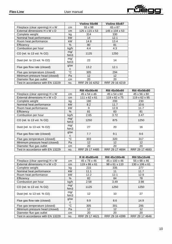
3.7. Technical data The values listed in the following tables either depend on the particular design or were established during
a type test in accordance with EN 13229.
Violino 45x60 Violino 45x80 Violino 55x73
Fireplace (clear opening) H x W cm 45 x 60 45 x 80 55 x 73
External dimensions H x W x D cm 111 x 77 x 53 111 x 97 x 53 125 x 89 x 53
Complete weight kg 220 280 280
Nominal heat performance kW 8.4 9.2 12.5
Room heat performance kW 9.2 10.1 13.7
Efficiency % 84 80 80
Combustion per hour kg/h 2.6 4.2
CO (rel. to 13 vol. % O2) mg/Nm3
1250 1125 1000
Dust (rel. to 13 vol. % O2) mg/Nm3
11 23 10
Flue gas flow rate (closed) g/se
c 7.9
10.6 12.9
Flue gas temperature (closed) °C 256 273 304
Minimum pressure head (closed) Pa 12 12 12
Diameter flue gas outlet cm 20 20 20
Test in accordance with EN 13229 no. RRF 29 15 4144 RRF 29 15 4184 RRF 29 16 4303
Flex-Line User manual
10
Violino 55x98 Violino 65x87
Fireplace (clear opening) H x W cm 55 x 98 65 x 87
External dimensions H x W x D cm 125 x 115 x 53 145 x 104 x 53
Complete weight kg 314 330
Nominal heat performance kW 14 12.1
Room heat performance kW 14.8 13.4
Efficiency % 80 81
Combustion per hour kg/h 4.4 4.3
CO (rel. to 13 vol. % O2) mg/Nm3
1125 1250
Dust (rel. to 13 vol. % O2) mg/Nm3
22 14
Flue gas flow rate (closed) g/se
c 13.2 12.1
Flue gas temperature (closed) °C 305 294
Minimum pressure head (closed) Pa 12 12
Diameter flue gas outlet cm 20 20
Test in accordance with EN 13229 no. RRF 29 16 4252 RRF 29 16 4219
RIII 45x56x46 RIII 45x56x60 RIII 45x56x80
Fireplace (clear opening) H x W cm 45 x 54 x 46 45 x 54 x 60 45 x 56 x 80
External dimensions H x W x D cm 111 x 62 x 61 119 x 62 x 75 119 x 62 x 95
Complete weight kg 180 200 230
Nominal heat performance kW 8.2 11.7 10.6
Room heat performance kW 9 12.9 11.7
Efficiency % 81 83 81
Combustion per hour kg/h 2.65 3.72 3.47
CO (rel. to 13 vol. % O2) mg/Nm3
1250 875 1250
Dust (rel. to 13 vol. % O2) mg/Nm3
27 20 16
Flue gas flow rate (closed) g/se
c 7.7 9.1 9.6
Flue gas temperature (closed) °C 303 320 317
Minimum pressure head (closed) Pa 12 12 12
Diameter flue gas outlet cm 20 20 20
Test in accordance with EN 13229 no. RRF 29 17 4485 RRF 29 17 4694 RRF 29 17 4693
R III 45x80x46 RIII 45x100x46 RIII 55x10x46
Fireplace (clear opening) H x W cm 45 x 78 x 46 45 x 100 x 46 55 x 98 x 46
External dimensions H x W x D cm 119 x 86 x 61 98 x 61 x 110 130 x 106 x 61
Complete weight kg 215 335 277
Nominal heat performance kW 11.1 11 11.7
Room heat performance kW 12.2 12.1 12.9
Efficiency % 82 84 78
Combustion per hour kg/h 2.58 3.49 3.98
CO (rel. to 13 vol. % O2) mg/Nm3
1125 1250 1250
Dust (rel. to 13 vol. % O2) mg/Nm3
12 10 27
Flue gas flow rate (closed) g/se
c 9.9 8.6 14.9
Flue gas temperature (closed) °C 305 301 295
Minimum pressure head (closed) Pa 12 12 12
Diameter flue gas outlet cm 20 20 20
Test in accordance with EN 13229 no. RRF 29 17 4621 RRF 29 16 4399 RRF 29 17 4646

Flex-Line User manual
11
3.8. Firebox lining with Thermobrikk® The firebox linings with Thermobrikk® consist of several wall- and floor components. The following images
apply to all shapes and sizes of Rüegg fireplaces fitted with Thermobrikk®.
Install the firebox lining in the specified order and dismantle the individual components in the reverse
order.
Set up the wall elements in the firebox. Start in the corner of the back and side wall.
Set up the wall elements in the firebox. Push behind the sheet metal tab in the area of the firebox opening. Always place the cut-to-size wall elements forwards in the area of the firebox opening!
Fill the back and side walls with wall elements. Push wall elements together without any gap.
Fasten the mounting bracket to the firebox wall with screws.
Place all floor elements carefully on the floor of the sheet metal. Evenly distribute any lateral play between the floor elements.

Flex-Line User manual
12
3.9. Type plate
Important performance data is captured on the type plate. The type
plate can be found on the right-hand side of the appliance on the
inside of the lining.
Lateral thermal insulation / Isolation latérale: XX cm mineral wool / Fibre minérale thermal insulation behind / Isolation arrière: XX cm ρ ≥ 100 kg/m³;λr ≤ 0.035 W/(mK); thermal insulation underneath / Isolation dessous: XX cm T ≥ 750° C Minimum safety spacing from combustible materials / Distance de sécurité minimale aux éléments inflammable: XXX cm
Nominal heat performance / Puissance nominale: XX.X kW thermal performance range / Plage de puissance: X.X - XX.X kW
CO (13% O2): X.X% / XXXX mg/Nm³ Dust / Poussière: XX.X mg/Nm³ Flue gas temperature / Température des fumées: XXX° C Efficiency / Rendement: XX.X%
from the test in accordance with EN 13229
Testing laboratory indicator / No. d'identification du lab. d'essai: 1625 Test standard / Essai suivant norme: EN 13229:2006, A1:2003, A2:2004 Heating element / Foyer: EN 13229-WA VKF no. / No. AEAI: XXXXX
Multiple connections permitted only with a self-closing door Le raccordement multiple n'est autorisé que pour des foyers à fermeture de porte automatique
May only be operated as a temporary-burning fireplace Foyer ne pouvant être utilisé qu'en feu intermittent (INT) Read
and follow the manual Lisez attentivement la notice d'utilisation
Sole recommended fuel: Natural wood Combustible agrée: Bois naturel
Rüegg Cheminée AG CH-8126 Zumikon www.ruegg-cheminee.com
Fireplace insert name
Manufacturer’s number Date of manufacture
No. de fabrication XXXXX Date de fabrication dd.mm.yyyy

Flex-Line User manual
13
3.10. Operating elements The overview shows a possible layout option for the operating elements. The number and the layout of
the operating elements may vary depending on the model. Not all the operating elements mentioned
need be present on your fireplace.
6 8
7 1. Air regulator
2. Fire door
3. Air grille ‒ Ambient air inlet
4. Valve flap for combustion air
5. Valve flap for convection air
6. Air grille ‒ Warm air outlet
7. Handle for flue gas flap
8. Regulator for fan
1 2 4
3 5

Flex-Line User manual
14
3.11. Fire door The fire door on your fireplace can either be pushed up or swivelled open (swing out). It is constructed
either as a single unit or in two parts, depending on the shape. The fire door consists of the following main
components:
▪ Gasket
▪ Frame
▪ Ceramic glass
▪ Handle
▪ Hinge
▪ Locking mechanism
Push up / push down
The fire door can easily be pushed up and down by hand. Always hold the fire door firmly by the handle
when pushing.
Disengage/swivel open (swing out)
Disengage the fire door as shown in the picture. Remove all objects from the swivel range and
swing/swivel the fire door carefully outwards.
Close (snap shut)/engage
Remove all objects from the swivel range and close/snap the fire door carefully shut. The fire door locks
automatically.
Violino:
View from the front Locking detail View from the side
RII, RIII:
View from the front Locking detail View from above

Flex-Line User manual
15
3.12. Air regulator The supply of combustion air to the firebox is regulated with the air regulator. Depending on the operating
condition, for ideal combustion more or less air must be supplied to the fire. The air regulator is variably
adjustable. The symbol in the glass indicates in what setting more or less air is supplied.
Move the air regulator manually to the desired position.
1. CLOSED
2. OPEN
1 2
3.13. Flue gas valve The flue gas discharge is regulated in the flue gas system using the flue gas valve. The flue gas valve
must always be open during the operation. The flue gas valve is variably adjustable. If there is a strong
draught in the flue gas system the flue gas valve can be closed slightly and the draught restricted in this
way. The symbol on the twist grip indicates the position the flue gas valve is in.
Move the grip to the desired position by hand.
1 2 1. CLOSED
2. OPEN
Flex-Line User manual
16
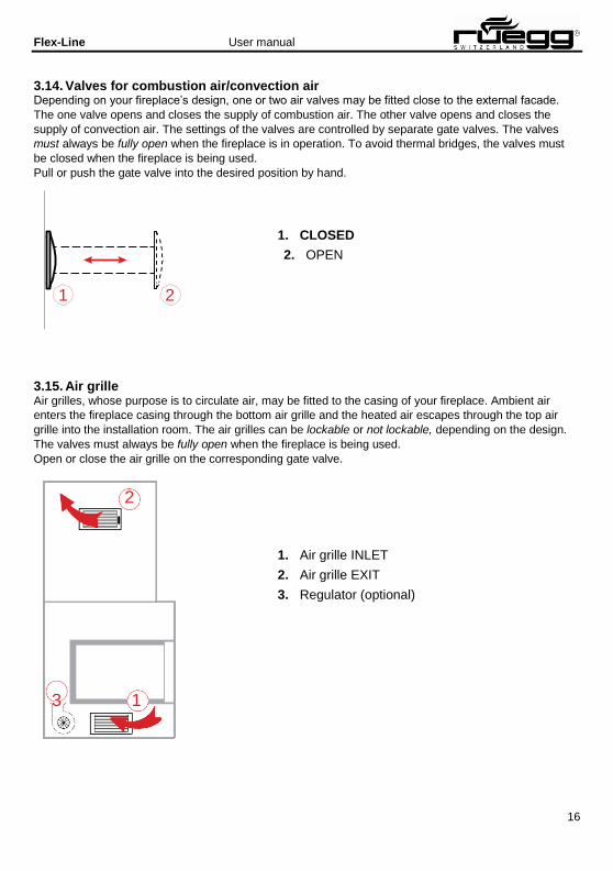
3.14. Valves for combustion air/convection air Depending on your fireplace’s design, one or two air valves may be fitted close to the external facade.
The one valve opens and closes the supply of combustion air. The other valve opens and closes the
supply of convection air. The settings of the valves are controlled by separate gate valves. The valves
must always be fully open when the fireplace is in operation. To avoid thermal bridges, the valves must
be closed when the fireplace is being used.
Pull or push the gate valve into the desired position by hand.
1. CLOSED
2. OPEN
1 2
3.15. Air grille Air grilles, whose purpose is to circulate air, may be fitted to the casing of your fireplace. Ambient air
enters the fireplace casing through the bottom air grille and the heated air escapes through the top air
grille into the installation room. The air grilles can be lockable or not lockable, depending on the design.
The valves must always be fully open when the fireplace is being used.
Open or close the air grille on the corresponding gate valve.
2
1. Air grille INLET
2. Air grille EXIT
3. Regulator (optional)
3 1

Flex-Line User manual
17
The air grilles are fixed into the casing with clamping plates. If necessary, you can remove the air grille by
pulling it out and fit it again by pushing it back in.
3.16. Fan Depending on the design, a fan can be fitted in the substructure to your fireplace or outside the casing.
The fan increases the system’s air flow and distributes the warmed air in the installation room by means
of the air grilles. The speed of the fan can be variably adjusted by hand using the rotary control. The fan
should always be switched on when the fireplace is being used.
Turn the regulator to the desired position by hand.
2 3 1. SWITCHED OFF
2. SWITCHED ON (large air flow)
3. SWITCHED ON (small air flow)
1

Flex-Line User manual
18
4. Information about safety
4.1. Safety spacing in the heat-radiation area Flammable materials in the heat-radiation area of the fire door can be ignited. To avoid fires, keep the
safety spacing of X [cm] between combustible materials and the fire door of your system.
Y Y Y
X X X
X
X X X
X
Appliance X
[cm] Y
[cm]
Violino 45x60 125 -
Violino 45x80 150 -
Violino 55x73 130 -
Violino 55x98 150 -
Violino 65x87 170 -
RIII 45x56x46 80 70
RIII 45x56x60 60 60
RIII 45x56x80 60 70
RIII 45x80x46 100 70
RIII 45x100x46 100 60
RIII 55x100x46 130 60
4.2. Air grille Air grilles can be fitted in the casing depending on the type and function of your system. The convention
air must be freely able to circulate through this air grille. Ensure that the air grilles are not closed or
covered by any objects.
4.3. Precoat Combustible floors must be protected around the fire doors by a non-combustible precoat. The precoat on
your fireplace may not be removed.
Flex-Line User manual
19
4.4. Fire door Your fire door is self-closing or not self-closing depending on the design. Self-closing fire doors have a
safety function combined with other combustion units that are connected to the same chimney.
No manipulation or changes to the fire door are permitted. Have the defective fire doors and gaskets
repaired by the specialist installer straight away.
4.5. Combustion air Depending on the type and function of your system the combustion air is fed into the system from the
installation room (dependent upon ambient air) or from the outside (separated from ambient air). Ensure
that sufficient ambient air can always flow in when several systems in a composite heating system are
working simultaneously. Appliances that extract ambient air (extractor hoods, ventilation systems, central
dust extraction units etc.) may not affect the operating safety of your system.
System dependent upon ambient air
Ensure that sufficient fresh air is always able to flow into the installation room.
System separate from ambient air
Ensure that the fresh air vent on the external facade or in the basement of the building is neither closed
nor covered by any objects.
4.6. Responsibility to inspect Small children and young people can sustain severe burns on the surfaces from the system when it is
hot.
Always supervise small children when the system is operating. Explain to young people the risk of burns
from the fireplace when it is in use.
4.7. Damage to the system Operating damaged or incomplete systems is not permitted!
Do not carry out repairs to your system yourself. Have the defective systems repaired immediately by the
specialist installer.
4.8. Changes to the system Unauthorised changes to your system or individual parts are not permitted.
The manufacturer must always authorise any changes to the fireplace insert. Have any changes to your
system carried out by the specialist installer.
4.9. Care and maintenance Support the long-standing and safe operation of your system with a little maintenance and care.
Clean your system regularly and have it checked periodically by a specialist.
Flex-Line User manual
20
4.10. Chimney fire In very rare cases, a chimney fire can occur. Do not try to extinguish it with water under any
circumstances! Quickly expanding steam caused by the heat may damage your system!
Possible causes of a chimney fire:
▪ Burning fuels that are not permitted
▪ Inadequate cleaning of the flue gas system
▪ System has been out of service for several years
How to recognise a chimney fire:
▪ Flames from the chimney mouth
▪ Significant flying sparks
▪ Strong smoke and odour pollution
▪ External surface of the chimney is hot
Take the following measures:
▪ Close all air feeds into the systems
▪ Evacuate people and animals from the building
▪ Alert the fire brigade
▪ Allow the chimney to burn out
▪ Have the chimney checked by a specialist
Flex-Line User manual
21
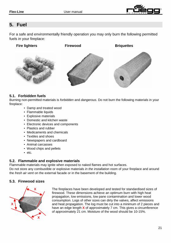
5. Fuel
For a safe and environmentally friendly operation you may only burn the following permitted
fuels in your fireplace:
Fire lighters Firewood Briquettes
5.1. Forbidden fuels Burning non-permitted materials is forbidden and dangerous. Do not burn the following materials in your
fireplace:
▪ Damp and treated wood
▪ Flammable liquids
▪ Explosive materials
▪ Domestic and kitchen waste
▪ Electronic devices and components
▪ Plastics and rubber
▪ Medicaments and chemicals
▪ Textiles and shoes
▪ Newspapers and cardboard
▪ Animal carcasses
▪ Wood chips and pellets
▪ etc.
5.2. Flammable and explosive materials Flammable materials may ignite when exposed to naked flames and hot surfaces.
Do not store any combustible or explosive materials in the installation room of your fireplace and around
the fresh air vent on the external facade or in the basement of the building.
5.3. Firewood sizes
The fireplaces have been developed and tested for standardised sizes of firewood. These dimensions achieve an optimum burn with high heat propagation, low emissions, low pane contamination and lower wood consumption. Logs of other sizes can dirty the valves, affect emissions and heat propagation. The log must be cut into a minimum of 2 pieces and have an edge length X of approximately 7 cm. This gives a circumference of approximately 21 cm. Moisture of the wood should be 10-15%.
X
X
X

Flex-Line User manual
22
6. Information about operation
Risk of fire!
Flammable materials may ignite when exposed to naked flames and hot surfaces.
▪ Do not store combustible materials close to the fireplace
▪ Maintain a safe distance from the system
Forbidden fuels!
The use of forbidden fuels may cause toxic flue gas emissions and damage to the
system.
▪ Use only the permitted fuels
▪ Do not exceed the maximum loading quantity
Flue gases!
Flue gases can escape into the installation room through an open or badly sealed
fire door.
▪ Always close fire door
▪ Have defective seals replaced straight away
Hot surfaces!
Contact with hot surfaces may result in severe burns.
▪ Constantly supervise small children
▪ Explain the dangers to young people
▪ Do not touch hot surfaces
▪ Use safety gloves

Flex-Line User manual
23
7. Commissioning Take your system into service for the first time in conjunction with a specialist installer. He will explain in
detail the functions and how to handle the operating elements. The materials of the casing must be
completely dry during initial commissioning. Increase the volume of fuel added to the maximum quantity
in three steps.
Foreign odours!
The colour of the fireplace insert must be fully baked in during the initial firings. This is why your system
may give off unpleasant odours.
▪ Open all windows in the installation area
▪ Close all doors in the installation area
Strange sounds!
Thermal expansion of the various materials on the fireplace insert may, in rare cases, result in cracking or
ticking sounds as it heats up or cools down. These sounds are not dangerous and do not affect the
operational safety and functionality of your system!
7.1. Complete combustion Only ash remains behind in the firebox after complete combustion. Complete combustion of firewood is
always divided into three phases.
Phase 1: Drying out
The residual humidity in the firewood evaporates at temperatures above 100°C.
Phase 2: Outgassing
The volatile elements of the firewood make up around 85% of the wood. These volatilise and ignite at
temperatures above 230°C.
Phase 3: Combustion
The burning charcoal equates to around 15% of the energy content and burns without any visible flame at
temperatures above 800°C.
Flex-Line User manual
24
7.2. Reduce harmful substances Make an active contribution to reducing harmful emissions with a little effort. The most important
measures here are:
▪ Fire with top-down combustion
▪ Use permitted fuels
▪ Keep to the maximum feed quantity
▪ Burn several smaller logs instead of one large log
▪ Adjust the operating elements to the particular operating state
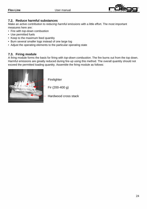
7.3. Firing module A firing module forms the basis for firing with top-down combustion. The fire burns out from the top down.
Harmful emissions are greatly reduced during fire-up using this method. The overall quantity should not
exceed the permitted loading quantity. Assemble the firing module as follows:
Firelighter
Fir (200-400 g)
Hardwood cross stack

Flex-Line User manual
25
7.4. Putting on wood Each appliance has a different firebox and therefore different flow relationships. To achieve the correct
combustion with good emissions the wood must be placed in the appliances in the following way.
Violino 45x80, 55x73, 55x98, 65x87 Violino 45x60
RIII 55x100x46, 45x100x46, 45x80x46 RIII 45x56x46, 45x56x60, 45x56x80
7.5. Effect of weathering In rare cases, external temperatures over 15°C can result in a blockage in the flue gas system. As the
temperature difference between the flue gas system and the external air is too low, too little discharge
pressure is built up in the flue gas channel. The flue gases are not dissipated. A so-called pilot fire, which
produces a great deal of heat in a short time, can under some circumstances clear the blockage.
Proceed as follows:
1. Fully open the flue gas valve
2. Loosely roll together 2 to 4 sheets of newspaper
3. Open fire door
4. Ignite newspaper and hold in the smoke outlet
If the blockage is not cleared despite several pilot fires, you should refrain from starting a fire in the
fireplace. In areas with frequent severe weather conditions, installing a flue gas fan can provide a remedy.

Flex-Line User manual
26
Flue gas valve (optional) x –
Combustion air valve (optional) x –
Convection air valve (optional) x –
Air grille (optional) x –
Air regulator x x
Fan (optional)
7.6. Preparing the system Proceed in the specified sequence when preparing your system.
1. Remove cold ash from the firebox (see Section 9)
2. Clean ceramic glass
3. Prepare the fuel
4. Set up firing module
5. Fully open combustion air valve
6. Fully open flue gas valve
7. Ensure there is a supply of combustion air
8. Fully open air grille on the casing
7.7. Fire Proceed in the above sequence when firing:
1. Check the correct setting of all operating elements (if available on your system).
2. Switch off any mechanisms that extract ambient air (extractor hoods, ventilation systems, central dust
evacuation units etc.).
3. Open the fire door.
4. Ignite the firelighter on the firing module with a match or a lighter.
5. Close the fire door.
Operating element open closed
– Off –
7.8. Loading in fuel Proceed in the following order when loading in fuel.
1. Check the correct setting of all operating elements (same setting as firing).
2. Open the fire door.
3. Load in the permitted quantity of fuel.
4. Close the fire door.
Flex-Line User manual
27
Flue gas valve (optional) 1/2 –
Combustion air valve (optional) x –
Convection air valve (optional) x –
Air grille (optional) x –
Air regulator 1/2 –
Fan (optional)
Flue gas valve (optional) – x
Combustion air valve (optional) – x
Convection air valve (optional) – x
Air grille (optional) x –
Air regulator – x
Fan (optional) – Off –
7.9. Firing with full load Set the operating elements as follows with full load when firing:
Operating element open closed
– On –
The settings may vary depending on the system and the weather. Contact our specialist installer for the optimal setting for your system.
7.10. Firing with a light load When firing with a light load the operating elements should be set in such a way that the glow in the
firebox is maintained for as long as possible. This allows the residual heat to be used in a sensible way as
far as energy is concerned. This operating state is generally produced at the end of a firing cycle before
the system is taken out of service.
Danger of muffled explosion! If the operating elements are set to light load too early, this can result in a lack of oxygen in the firebox. A
sudden inflow of air can cause a muffled explosion and damage the system.
▪ Adjust the operating elements only if no naked flames have been visible for more than five minutes.
▪ Do not open the fire door if you suspect a lack of oxygen.
▪ If you suspect a lack of oxygen open the air regulator slowly and in several stages.
Set the operating elements as follows with light load when firing:
Operating element open closed

Flex-Line User manual
28
Flue gas valve (optional) – x
Combustion air valve (optional) – x
Convection air valve (optional) – x
Air grille (optional) – x
Air regulator – x
Fan (optional)
8. Closing down
Danger of muffled explosion!
If the operating elements are set to light load too early, this can result in a lack of oxygen in the firebox. A
sudden inflow of air can cause a muffled explosion and damage the system.
▪ Adjust the operating elements only if no naked flames have been visible for more than five minutes.
▪ Do not open the fire door if you suspect a lack of oxygen.
▪ If you suspect a lack of oxygen open the air regulator slowly and in several stages.
Set the operating elements as follows on the system that has cooled down:
Operating element open closed
– Off –
8.1. Malfunctions Malfunctions may occur to your system in rare cases. The following table gives an overview of possible
causes and remedial action. Inform your specialist installer if the remedial action has been unsuccessful.
Fault: Flue gas is not diverted off properly through the chimney.
Possible causes:
▪ Is the flue gas valve closed?
▪ Too little combustion air?
▪ Negative pressure in the installation area?
Remedial action:
▪ Open flue gas valve
▪ Open air regulator
▪ Open combustion air valve ▪ Open or tilt windows
If unsuccessful
▪ Allow fire to go out
▪ Check cooled-down system
Fault: Even after several combustions the casing does not get really warm.
Possible causes:
▪ Is the fuel quantity correct? ▪ Combustion and flame pattern
correct?
▪ Is too much heat being lost through
the chimney?
Remedial action:
▪ Load in the right quantity of fuel
▪ Adjust air regulator
▪ Close the flue gas valve further
If unsuccessful
▪ Allow fire to go out
▪ Check cooled-down system
▪ Inform specialist installer
Flex-Line User manual
29
Fault: Fire burns out very quickly and uncontrolled.
Possible causes:
▪ Is the air regulator open?
▪ Is the flue gas valve fully open?
▪ Is the fire door open?
Remedial action:
▪ Reduce air regulator
▪ Reduce flue gas valve
▪ Close fire door
If unsuccessful
▪ Check cooled-down system
▪ Inform specialist installer
Fault: Fire burns poorly and smoulders
Possible causes:
▪ Too little combustion air?
▪ Is the flue gas valve closed?
▪ Wrong fuel?
▪ Is the fuel quantity correct?
▪ Are the logs too big? ▪ Is the wood too wet? ▪ Too little starter firewood?
Remedial action:
▪ Open air regulator
▪ Open flue gas valve
▪ Use permitted fuels
▪ Load on fuel in the permitted
quantity
▪ Load on several small logs
If unsuccessful
▪ Allow fire to go out
▪ Check cooled-down system
▪ Inform specialist installer
Fault: Ceramic glass on the fire door rusts over very quickly.
Possible causes:
▪ Too little combustion air?
▪ Is the flue gas valve closed?
▪ Wrong fuel?
▪ Is the fuel quantity correct?
▪ Are the logs too big?
Remedial action:
▪ Open air regulator
▪ Open flue gas valve
▪ Use permitted fuels
▪ Load on fuel in the permitted
quantity
▪ Load on several small logs
If unsuccessful
▪ Inform specialist installer
Fault: Unpleasant foreign odours in the installation room.
Possible causes:
▪ Are there any objects on the casing
or in the heat-radiation area?
▪ Is there any dust on the casing or in cavities? ▪ Have more than three firing intervals already been carried out?
Remedial action:
▪ Remove objects ▪ Clean casing and cavities
▪ Burn in paint at high temperature
If unsuccessful
▪ Allow fire to go out
▪ Check cooled-down system
▪ Inform specialist installer

Flex-Line User manual
30
9. Information about care and maintenance
Regular cleaning and maintenance of the components promotes operational safety and
increases your system’s service life.
Hot surfaces!
Contact with hot surfaces may result in severe burns.
▪ Carry out cleaning, inspection or maintenance work to the cooled-down system
Risk of fire!
Embers can remain in the ashes over several days and cause a fire.
▪ Allow ashes to cool completely
▪ Fill fireproof containers with ash
Ceramic glass
Unsuitable liquids and cleaning agents will damage the surface of ceramic glass.
▪ Use only permitted liquids and cleaning agents
▪ Follow maintenance information
Flex-Line User manual
31
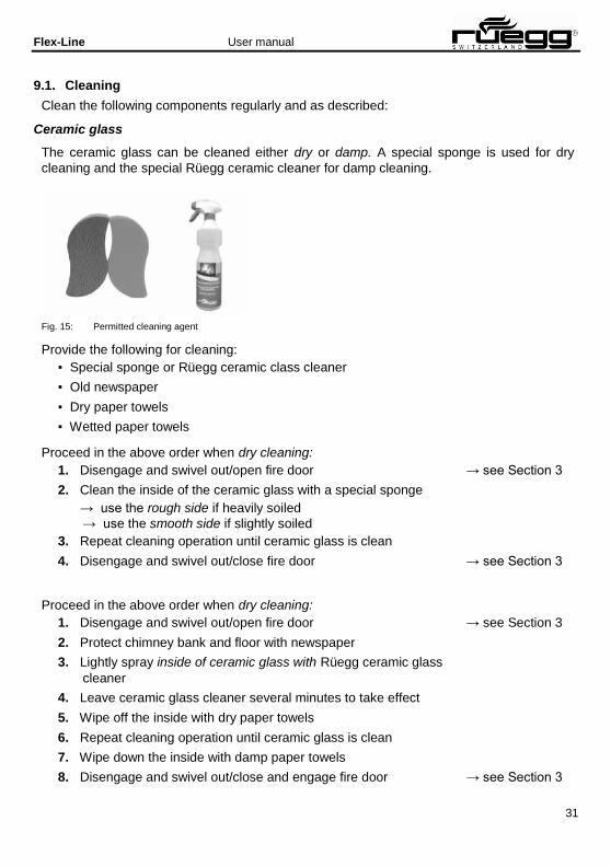
9.1. Cleaning
Clean the following components regularly and as described:
Ceramic glass
The ceramic glass can be cleaned either dry or damp. A special sponge is used for dry
cleaning and the special Rüegg ceramic cleaner for damp cleaning.
Fig. 15: Permitted cleaning agent
Provide the following for cleaning:
▪ Special sponge or Rüegg ceramic class cleaner
▪ Old newspaper
▪ Dry paper towels
▪ Wetted paper towels
Proceed in the above order when dry cleaning:
1. Disengage and swivel out/open fire door → see Section 3
2. Clean the inside of the ceramic glass with a special sponge
→ use the rough side if heavily soiled
→ use the smooth side if slightly soiled
3. Repeat cleaning operation until ceramic glass is clean
4. Disengage and swivel out/close fire door → see Section 3
Proceed in the above order when dry cleaning:
1. Disengage and swivel out/open fire door → see Section 3
2. Protect chimney bank and floor with newspaper
3. Lightly spray inside of ceramic glass with Rüegg ceramic glass
cleaner
4. Leave ceramic glass cleaner several minutes to take effect
5. Wipe off the inside with dry paper towels
6. Repeat cleaning operation until ceramic glass is clean
7. Wipe down the inside with damp paper towels
8. Disengage and swivel out/close and engage fire door → see Section 3

Flex-Line User manual
32
9. Lightly spray outside of ceramic glass with Rüegg ceramic glass
cleaner
10. Wipe down the inside with dry paper towels
11. Repeat cleaning operation until ceramic glass is clean
12. Wipe down the inside of ceramic glass with damp paper towels
13. Disengage and swivel out/close and engage fire door → see Section 3
Firebox
Remove the completely cooled ashes regularly from the firebox. To do this, either use a
conventional ash vacuum cleaner or a hand brush with metallic dustpan. Place the ashes
into a sealable, fireproof container and dispose of this, if necessary, together with your
household waste. Please follow the local regulations if you do.
Provide the following for cleaning:
▪ Sealable, fireproof container
▪ Ash vacuum cleaner or dustpan with hand brush
Proceed in the above order when cleaning:
1. Push up fire door → see Section 3
2. Remove ash from the fire floor
3. Close fire door → see Section 3
Air grille
Over time, dust can collect on the air grilles and in the cavities behind. The convection air
that circulates during the operation moves the dust in the installation area. Improve the indoor
climate in the installation area by regularly cleaning the air grille and cavities.
Provide the following for cleaning:
▪ Vacuum cleaner
Proceed in the above order when cleaning:
1. Remove air grille → see Section 3
2. Clean cavity with vacuum cleaner
3. Clean air grille with vacuum cleaner
4. Fit air grille → see Section 3
Caution: Do not allow any foreign bodies to get into the hot air chambers. They may ignite or
cause negative or harmful odours to develop over time. Have any objects removed by a
specialist before using the system.

Flex-Line User manual
33
Air fitting
In systems that are separated from ambient air, the air fitting for the combustion air and/or
convention air can either be fitted on the ceiling/wall of the room in the basement or on the
external facade of the building. To ensure the system works properly, the air fittings must
always be kept clean. Free any air fittings fitted to the external facade from any overgrowing
plants and regularly clean all air fittings.
Provide the following for cleaning:
▪ Garden shears
▪ Vacuum cleaner
Proceed in the above order when cleaning:
1. Cut back plants
2. Remove air grille → see Chapter 3
3. Clean pipe with vacuum cleaner
4. Clean air grille with vacuum cleaner
5. Fit air grille → see Section 3
Flue gas system
Soot and flue gas particles are deposited in the flue gas system. The flue gas system must
be cleaned regularly to ensure it works properly and safely. Cleaning the flue gas system
yourself is not permitted!
Always have the flue gas system cleaned by a specialist expert.
9.2. Checks
Regularly check the system when cold.
... check that the air grille and air fitting are clean and have an unobstructed cross section.
... check the seal on the swivelled open fire door to ensure that it is intact and shows no defects.
... check the draught (the air circulation) in the chimney, in particular after the system has
not been used for a while.
9.3. Maintenance
Your system is generally maintenance free. You can clean the system when cold with a clean
cloth and then carefully spray with WD40 multispray, if necessary.

Flex-Line User manual
34
9.4. Repair
Operating defective or incomplete systems is not permitted!
Replace defective wall and floor components of the firebox casing as described in Section
5.8. To supply the correct spare parts, we need the details about the device type and the
production date as shown on the type plate in Section 5.9.
Inform your specialist installer if....
... the flue gas valve is blocked.
... the air valve for combustion air is blocked.
... the air valve for convection air is blocked.
... the gasket on the fire door is defective or incomplete.
... the fire door is blocked.
... the locking mechanism to the fire door is defective.
... the fan for convection air is defective.
... you do not intend to replace wall or floor parts in the firebox casing yourself.
9.5. Spare parts
Moving parts and gaskets wear during use. How quickly a component is worn is determined
primarily by the frequency and intensity of use. The components in your fireplace insert are
designed for a long service life.
Please contact your specialist installer in the event of any damage. They will be happy to
advise you and help you further. Always use the recommended original spare parts. Other
parts may damage your system and impair operational safety.
9.6. Warranty conditions
Please contact your specialist installer in the event of any damage. They will examine any
potential warranty claim with us and arrange for any further action to be taken. A claim may
be made against the guarantee only if the Rüegg warranty certificate has been completed in
full and sent to the following address:
Rüegg Cheminée Schweiz AG
Studbachstrasse 7
8340 Hinwil
Switzerland

Flex-Line User manual
35

Flex-Line User manual
36