FLENDER couplings - Siemens / 24 BA 3601 en 06/2012 FLENDER RUPEX® Couplings Types RWN and RWS with...
24
FLENDER couplings FLENDER RUPEX® Couplings Types RWN and RWS with axial backlash limitation Operating instructions BA 3601 en 06/2012
Transcript of FLENDER couplings - Siemens / 24 BA 3601 en 06/2012 FLENDER RUPEX® Couplings Types RWN and RWS with...

FLENDER couplings
FLENDER RUPEX®Couplings
Types RWN and RWSwith axial backlash limitation
Operating instructionsBA 3601 en 06/2012

2 / 24BA 3601 en 06/2012
FLENDER RUPEX®Couplings
Types RWN and RWSwith axial backlash limitation
Operating instructions
Translation of the original operating instructions
Technical data
Stocking spare parts
Maintenanceand repair
Faults, causesand remedy
Start-upand operation
Fitting
Notes
1
7
6
5
4
3
2

3 / 24BA 3601 en 06/2012
Notes and symbols in these operating instructions
Note: The term "operating instructions" will in the following also be shortened to "instructions" or "manual".
Legal notes
Warning-note concept
This manual comprises notes which must be observed for your personal safety and for preventing material damage.Notes for your personal safety are marked with a warning triangle or an "Ex" symbol (when applyingDirective 94/9/EC), those only for preventing material damage with a "STOP" sign.
WARNING! Imminent explosion!
The notes indicated by this symbol are given to prevent explosion damage.Disregarding these notes may result in serious injury or death.
WARNING! Imminent personal injury!
The notes indicated by this symbol are given to prevent personal injury.Disregarding these notes may result in serious injury or death.
WARNING! Imminent damage to the product!
The notes indicated by this symbol are given to prevent damage to the product.Disregarding these notes may result in material damage.
NOTE!
The notes indicated by this symbol must be treated as general operating information.Disregarding these notes may result in undesirable results or conditions.
WARNING! Hot surfaces!
The notes indicated by this symbol are made to prevent risk of burns due to hot surfacesand must always be observed.Disregarding these notes may result in light or serious injury.
Where there is more than one hazard, the warning note for whichever hazard is the most serious is always used.If in a warning note a warning triangle is used to warn of possible personal injury, a warning of material damage maybe added to the same warning note.
Qualified personnel
The product or system to which these instructions relate may be handled only by persons qualified for the workconcerned and in accordance with the instructions relating to the work concerned, particularly the safety andwarning notes contained in those instructions. Qualified personnel must be specially trained and have theexperience necessary to recognise risks associated with these products or systems and to avoid possible hazards.

4 / 24BA 3601 en 06/2012
Intended use of Siemens products
Observe also the following:
Siemens products must be used only for the applications provided for in the catalogue and the relevanttechnical documentation. If products and components of other makes are used, they must berecommended or approved by Siemens. The faultfree, safe operation of the products calls for propertransport, proper storage, erection, assembly, installation, startup, operation and maintenance. Thepermissible ambient conditions must be adhered to. Notes in the relevant documentations must beobserved.
Trademarks
All designations indicated with the registered industrial property mark ® are registered trademarks of Siemens AG.Other designations used in these instructions may be trademarks the use of which by third parties for their ownpurposes may infringe holders’ rights.
Exclusion of liability
We have checked the content of the instructions for compliance with the hard and software described.Nevertheless, variances may occur, and so we can offer no warranty for complete agreement. The informationgiven in these instructions is regularly checked, and any necessary corrections are included in subsequent editions.
Note on the EC Machinery Directive 2006/42/EC
Siemens couplings in the "FLENDER couplings" product range must be treated as "components" in the senseof the EC Machinery Directive 2006/42/EC.Therefore, Siemens needs not issue a declaration of incorporation.Information on safe fitting, safe startup and safe operation can be found in this instructions manual; in additionthe "warningnote concept" therein must be observed.

5 / 24BA 3601 en 06/2012
Contents
1. Technical data 6. . . . . . . . . . . . . . . . . . . . . . . . . . . . . . . . . . . . . . . . . . . . . . . . . . . . .1.1 Buffer (5) 6. . . . . . . . . . . . . . . . . . . . . . . . . . . . . . . . . . . . . . . . . . . . . . . . . . . . . . . . . . . . . . . . . . . . . . . . . .
2. Notes 8. . . . . . . . . . . . . . . . . . . . . . . . . . . . . . . . . . . . . . . . . . . . . . . . . . . . . . . . . . . . .2.1 Safety instructions and general notes 8. . . . . . . . . . . . . . . . . . . . . . . . . . . . . . . . . . . . . . . . . . . . . . . . . .
3. Fitting 9. . . . . . . . . . . . . . . . . . . . . . . . . . . . . . . . . . . . . . . . . . . . . . . . . . . . . . . . . . . . .3.1 Machining the finished bore 9. . . . . . . . . . . . . . . . . . . . . . . . . . . . . . . . . . . . . . . . . . . . . . . . . . . . . . . . . .3.2 Insertion of the parallel keyway 9. . . . . . . . . . . . . . . . . . . . . . . . . . . . . . . . . . . . . . . . . . . . . . . . . . . . . . . .3.3 Axial fastening 10. . . . . . . . . . . . . . . . . . . . . . . . . . . . . . . . . . . . . . . . . . . . . . . . . . . . . . . . . . . . . . . . . . . . . .3.4 Balancing after machining the finished bore 10. . . . . . . . . . . . . . . . . . . . . . . . . . . . . . . . . . . . . . . . . . . . .3.5 Mounting of the coupling parts with cylindrical and tapered bore with parallel key 11. . . . . . . . . . . . .3.6 Fitting of coupling parts with a cylindrical and tapered interference fit set up
for removal by oil-hydraulic shrinking-off 11. . . . . . . . . . . . . . . . . . . . . . . . . . . . . . . . . . . . . . . . . . . . . . . .3.7 Installation of the coupling 12. . . . . . . . . . . . . . . . . . . . . . . . . . . . . . . . . . . . . . . . . . . . . . . . . . . . . . . . . . . .3.8 Possible misalignments 13. . . . . . . . . . . . . . . . . . . . . . . . . . . . . . . . . . . . . . . . . . . . . . . . . . . . . . . . . . . . . .3.8.1 Axial misalignment 13. . . . . . . . . . . . . . . . . . . . . . . . . . . . . . . . . . . . . . . . . . . . . . . . . . . . . . . . . . . . . . . . . .3.8.2 Angular misalignment 13. . . . . . . . . . . . . . . . . . . . . . . . . . . . . . . . . . . . . . . . . . . . . . . . . . . . . . . . . . . . . . . .3.8.3 Radial misalignment 13. . . . . . . . . . . . . . . . . . . . . . . . . . . . . . . . . . . . . . . . . . . . . . . . . . . . . . . . . . . . . . . . .3.9 Alignment 14. . . . . . . . . . . . . . . . . . . . . . . . . . . . . . . . . . . . . . . . . . . . . . . . . . . . . . . . . . . . . . . . . . . . . . . . . .3.10 Shaft-displacement values during operation 14. . . . . . . . . . . . . . . . . . . . . . . . . . . . . . . . . . . . . . . . . . . . .3.11 Setting the axial backlash 15. . . . . . . . . . . . . . . . . . . . . . . . . . . . . . . . . . . . . . . . . . . . . . . . . . . . . . . . . . . .3.12 Assignment of the tightening torques and widths across flats 16. . . . . . . . . . . . . . . . . . . . . . . . . . . . . .
4. Start-up and operation 16. . . . . . . . . . . . . . . . . . . . . . . . . . . . . . . . . . . . . . . . . . . . .
5. Faults, causes and remedy 17. . . . . . . . . . . . . . . . . . . . . . . . . . . . . . . . . . . . . . . . .5.1 Possible cause of fault 17. . . . . . . . . . . . . . . . . . . . . . . . . . . . . . . . . . . . . . . . . . . . . . . . . . . . . . . . . . . . . . .5.2 Incorrect use 17. . . . . . . . . . . . . . . . . . . . . . . . . . . . . . . . . . . . . . . . . . . . . . . . . . . . . . . . . . . . . . . . . . . . . . .5.2.1 Frequent faults when selecting the coupling and/or coupling size 17. . . . . . . . . . . . . . . . . . . . . . . . . . .5.2.2 Frequent faults when fitting the coupling 18. . . . . . . . . . . . . . . . . . . . . . . . . . . . . . . . . . . . . . . . . . . . . . . .5.2.3 Frequent faults in maintenance 18. . . . . . . . . . . . . . . . . . . . . . . . . . . . . . . . . . . . . . . . . . . . . . . . . . . . . . . .
6. Maintenance and repair 19. . . . . . . . . . . . . . . . . . . . . . . . . . . . . . . . . . . . . . . . . . . .6.1 Maintenance interval 19. . . . . . . . . . . . . . . . . . . . . . . . . . . . . . . . . . . . . . . . . . . . . . . . . . . . . . . . . . . . . . . .6.2 Replacement of wearing parts 19. . . . . . . . . . . . . . . . . . . . . . . . . . . . . . . . . . . . . . . . . . . . . . . . . . . . . . . .6.2.1 Extract bolts for coupling sizes 450 to 1250 using the demounting box 20. . . . . . . . . . . . . . . . . . . . . .6.2.2 Extract bolts for coupling sizes 450 to 1250 with grease 20. . . . . . . . . . . . . . . . . . . . . . . . . . . . . . . . . . .6.3 Demounting the coupling parts in case of shaft-hub connection with parallel key 20. . . . . . . . . . . . . .6.4 Demounting of coupling parts with a cylindrical and tapered interference fit set up
for removal by oil-hydraulic shrinking-off 21. . . . . . . . . . . . . . . . . . . . . . . . . . . . . . . . . . . . . . . . . . . . . . . .
7. Stocking spare parts 22. . . . . . . . . . . . . . . . . . . . . . . . . . . . . . . . . . . . . . . . . . . . . . .7.1 Spare parts 22. . . . . . . . . . . . . . . . . . . . . . . . . . . . . . . . . . . . . . . . . . . . . . . . . . . . . . . . . . . . . . . . . . . . . . . .
6 / 24BA 3601 en 06/2012
1. Technical data
The instructions describe the coupling in horizontal mounting position with shaft-to-hub connectionby cylindrical or tapered bore with parallel key or press-fit seat. If other shaft-to-hub connections are used(e. g. involute splines according to the standard "DIN 5480") or if the coupling is installed in a vertical ortilted alignment, Siemens must be consulted.
If a dimensioned drawing has been made out for the coupling, the data in this drawing must be givenpriority. The dimensioned drawing including any other documents should be made available to the userof the system.
Parts numbers and parts descriptions in the spare parts drawing can be found in section 7. "Stocking spareparts" or the dimensioned drawing.
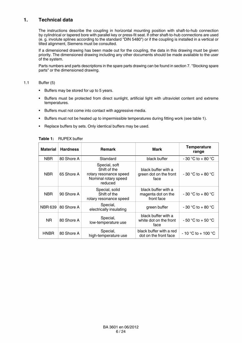
1.1 Buffer (5)
• Buffers may be stored for up to 5 years.
• Buffers must be protected from direct sunlight, artificial light with ultraviolet content and extremetemperatures.
• Buffers must not come into contact with aggressive media.
• Buffers must not be heated up to impermissible temperatures during fitting work (see table 1).
• Replace buffers by sets. Only identical buffers may be used.
Table 1: RUPEX buffer
Material Hardness Remark MarkTemperature
range
NBR 80 Shore A Standard black buffer - 30 °C to + 80 °C
NBR 65 Shore A
Special, softShift of the
rotary resonance speedNominal rotary speed
reduced
black buffer with agreen dot on the front
face- 30 °C to + 80 °C
NBR 90 Shore ASpecial, solid
Shift of therotary resonance speed
black buffer with amagenta dot on the
front face- 30 °C to + 80 °C
NBR 639 80 Shore ASpecial,
electrically insulatinggreen buffer - 30 °C to + 80 °C
NR 80 Shore ASpecial,
low-temperature use
black buffer with awhite dot on the front
face- 50 °C to + 50 °C
HNBR 80 Shore ASpecial,
high-temperature useblack buffer with a reddot on the front face
- 10 °C to + 100 °C

7 / 24BA 3601 en 06/2012
U2
∅D
1
S
P U1
∅N
D1
∅D
A
∅D
2
∅N
D2NL1 NL2
1 2
Fig. 1: Types RWN and RWS with axial backlash limitation
Table 2: Types RWN and RWS with axial backlash limitation
Size
Speed Maximum bore 1)
NL1NL2
Weight 2)
nmax. D1 D2 D1 D2 DA ND1 ND2 ND1 ND2 P S U1 U2 m m
RWN RWS RWN RWS RWN RWS RWN RWS
1/min 1/min mm mm mm mm mm mm mm mm mm mm mm mm mm mm kg kg
285 2650 3900 100 110 110 120 285 164 175 164 175 110 60 3 ... 6 32 30 45 45
320 2350 3500 110 120 125 130 320 180 192 180 192 125 60 3 ... 6 32 30 58 58
360 2100 3100 120 130 135 140 360 200 210 200 210 140 75 3 ... 6 42 42 85 85
400 2050 2800 140 140 150 150 400 230 230 230 230 160 75 3 ... 6 42 42 115 115
450 1800 2500 160 160 170 170 450 260 260 260 260 180 90 4 ... 7 52 52 165 170
500 1600 2200 180 180 190 190 500 290 290 290 290 200 90 4 ... 7 52 52 235 215
560 1450 2000140180200
140180200
165200210
165200210
560250300320
250300320
250300320
250300320
220 120 4 ... 8 68 68295310310
295315325
630 1280 1800140180220
140180220
165200235
165200235
630250300355
250300355
250300355
250300355
240 120 4 ... 8 68 68375395420
385405435
710 1150 1600160200240
160200240
190220250
190220250
710290330385
290330385
290330385
290330385
260 140 5 ... 9 80 80545535580
555570610
800 1000 1400180220260
180220260
210240280
210240280
800320360420
320360420
320360420
320360420
290 140 5 ... 9 80 80705715765
720740785
900 900 1250220260290
220260290
210240280310
210240280310
900360425465
360425465
320360425465
320360425465
320 160 5...10 90 90965
10301060
980101010701100
1000 810 1100240280320
240280320
230260300340
230260300340
1000395460515
395460515
355395460515
355395460515
350 160 5...10 90 90124013201390
1260130013801440
1120 700 1000
200250300350
200250300350
240270330370
240270330370
1120
360410495560
360410495560
360410495560
360410495560
380 180 6...11 100 100
1650164018001870
1700176018601960
1250 650 900
230280330380
230280330380
270300360400
270300360400
1250
410460540610
410460540610
410460540610
410460540610
420 180 6...11 100 100
2100215022802410
2210229024002560
1) Maximum bore with groove according to the standard "DIN 6885/1".
2) Weights are valid for maximum bores.

8 / 24BA 3601 en 06/2012
2. Notes
2.1 Safety instructions and general notes
All persons involved in the installation, operation, maintenance and repair of thecoupling or clutch must have read and understood these instructions and mustcomply with them at all times. Disregarding these instructions may cause damage tothe product and material and/or injury to persons. Damage caused by disregard ofthese instructions will result in exclusion of liability.
During transport, assembly, disassembly, operation and maintenance of the unit, the relevant safety andenvironmental regulations must be observed.
Lifting and load equipment for handling the components for transport must be suitablefor the weight of the coupling.
Store the coupling in a dry place. Apply adequate preservation.
Operators and users must not make any changes to the coupling themselves over and above the treatmentspecified in these instructions.
If there is any visible damage the coupling or clutch must not be fitted or put intooperation.
The coupling must not be operated unless housed in a suitable enclosure in accordance with the standardsapplying. This also applies to test runs and when checking the direction of rotation.
All work on the coupling must be carried out only when it is at a standstill. Secure the drive unit to preventunintentional switch-on. A notice should be attached to the ON switch stating clearly that work on thecoupling is in progress.
In addition to any generally prescribed personal safety equipment (such as safety shoes, safety clothing,helmet), handling the coupling requires wearing suitable safety gloves and suitable safety glasses!
Dispose or recycle the coupling according to the valid national regulations.
Only spare parts made by the manufacturer Siemens must be used.
Any enquiries should be addressed to:
Siemens AGSchlavenhorst 10046395 Bocholt
Tel.: +49 (0)2871 / 92-0Fax: +49 (0)2871 / 92-2596
9 / 24BA 3601 en 06/2012
3. Fitting
Coupling parts for oil-hydraulic shrinking are delivered in a finished machined state according to the order.
3.1 Machining the finished bore
Remove bolt (4) and buffer (5).
Depreserve and clean coupling parts (1; 2).
Clamp on surfaces marked with and align.
Insert finished bore. The maximum dimension of the bore according to section 1. "Technical data" mustbe observed.
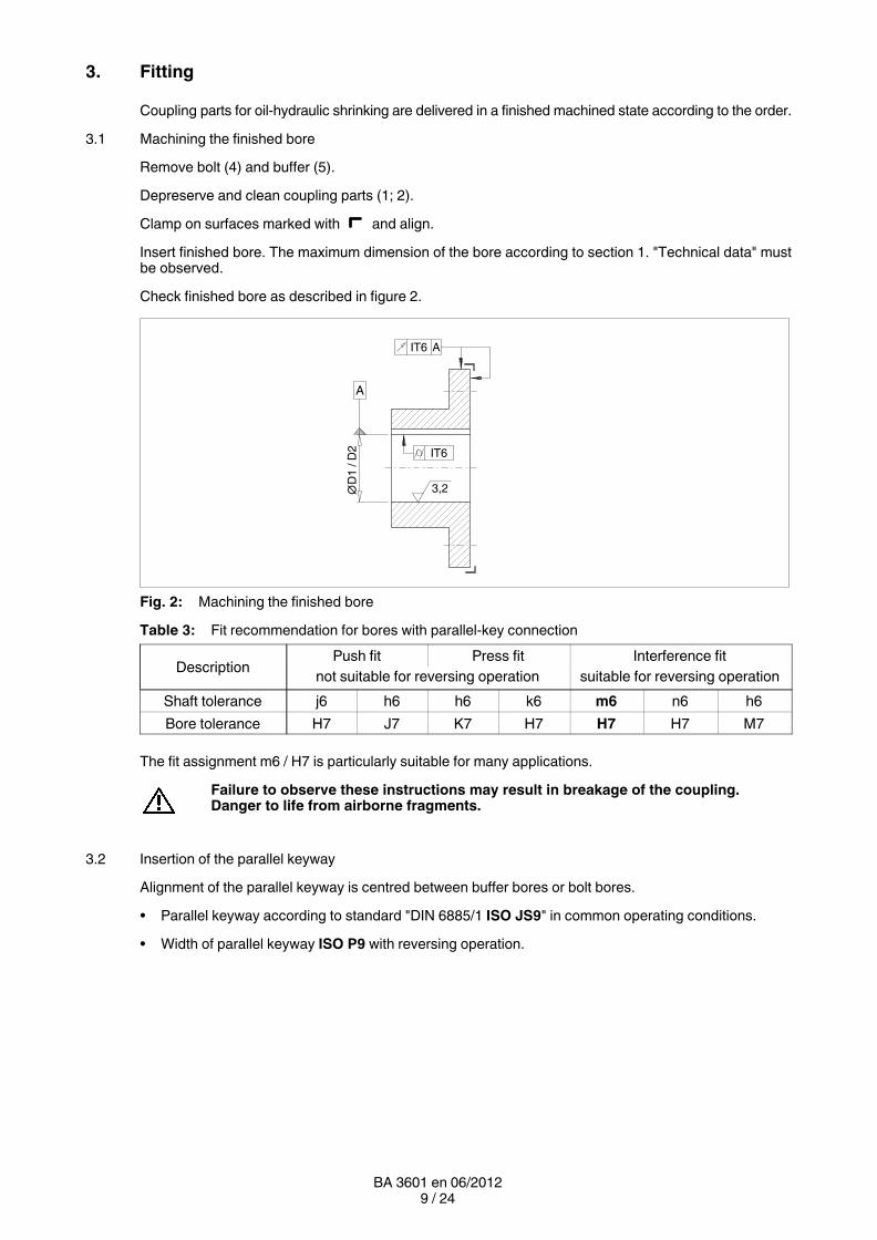
Check finished bore as described in figure 2.
A
IT6∅
D1
/ D
2A
IT6
3,2
Fig. 2: Machining the finished bore
Table 3: Fit recommendation for bores with parallel-key connection
DescriptionPush fit Press fit Interference fit
not suitable for reversing operation suitable for reversing operation
Shaft tolerance j6 h6 h6 k6 m6 n6 h6
Bore tolerance H7 J7 K7 H7 H7 H7 M7
The fit assignment m6 / H7 is particularly suitable for many applications.
Failure to observe these instructions may result in breakage of the coupling.Danger to life from airborne fragments.
3.2 Insertion of the parallel keyway
Alignment of the parallel keyway is centred between buffer bores or bolt bores.
• Parallel keyway according to standard "DIN 6885/1 ISO JS9" in common operating conditions.
• Width of parallel keyway ISO P9 with reversing operation.
10 / 24BA 3601 en 06/2012
3.3 Axial fastening
Arrange set screw on the parallel keyway.
Position of the set screw is about in the centre of the hub.
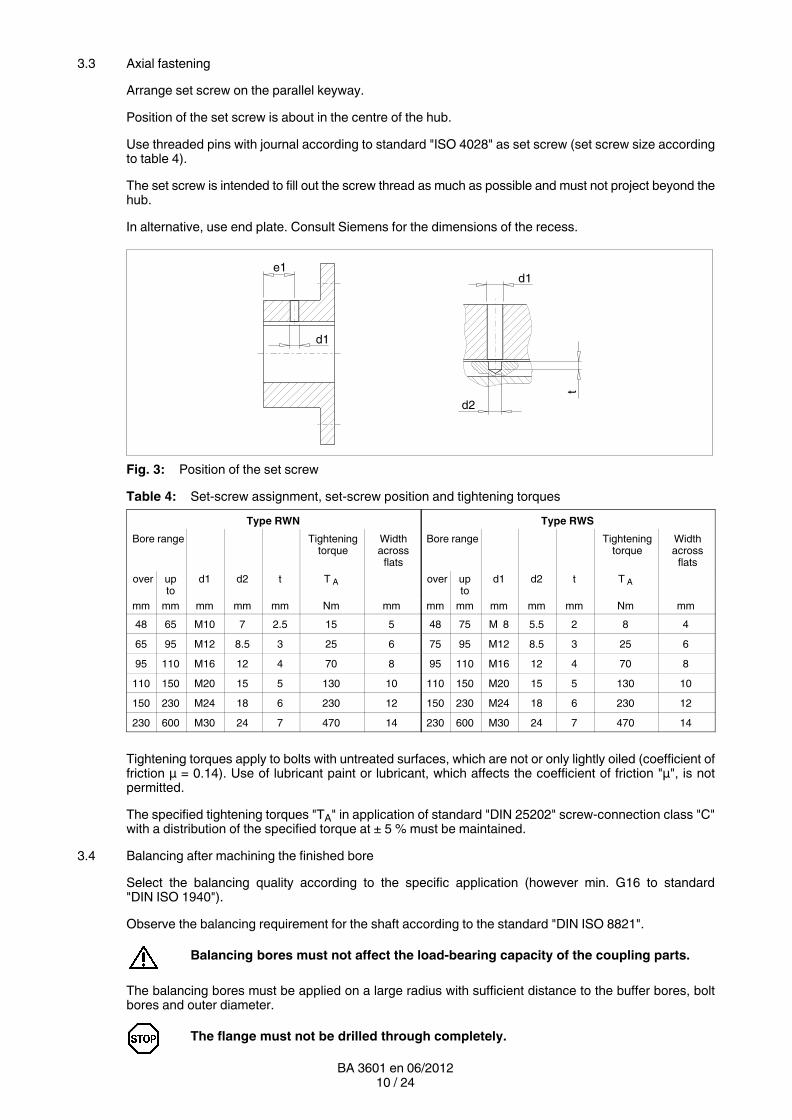
Use threaded pins with journal according to standard "ISO 4028" as set screw (set screw size accordingto table 4).
The set screw is intended to fill out the screw thread as much as possible and must not project beyond thehub.
In alternative, use end plate. Consult Siemens for the dimensions of the recess.
e1d1
d2
d1
t
Fig. 3: Position of the set screw
Table 4: Set-screw assignment, set-screw position and tightening torques
Type RWN Type RWS
Bore range Tighteningtorque
Widthacross
flats
Bore range Tighteningtorque
Widthacross
flats
over upto
d1 d2 t T A over upto
d1 d2 t T A
mm mm mm mm mm Nm mm mm mm mm mm mm Nm mm
48 65 M10 7 2.5 15 5 48 75 M 8 5.5 2 8 4
65 95 M12 8.5 3 25 6 75 95 M12 8.5 3 25 6
95 110 M16 12 4 70 8 95 110 M16 12 4 70 8
110 150 M20 15 5 130 10 110 150 M20 15 5 130 10
150 230 M24 18 6 230 12 150 230 M24 18 6 230 12
230 600 M30 24 7 470 14 230 600 M30 24 7 470 14
Tightening torques apply to bolts with untreated surfaces, which are not or only lightly oiled (coefficient offriction μ = 0.14). Use of lubricant paint or lubricant, which affects the coefficient of friction "μ", is notpermitted.
The specified tightening torques "TA" in application of standard "DIN 25202" screw-connection class "C"with a distribution of the specified torque at ± 5 % must be maintained.
3.4 Balancing after machining the finished bore
Select the balancing quality according to the specific application (however min. G16 to standard"DIN ISO 1940").
Observe the balancing requirement for the shaft according to the standard "DIN ISO 8821".
Balancing bores must not affect the load-bearing capacity of the coupling parts.
The balancing bores must be applied on a large radius with sufficient distance to the buffer bores, boltbores and outer diameter.
The flange must not be drilled through completely.
11 / 24BA 3601 en 06/2012
3.5 Mounting of the coupling parts with cylindrical and tapered bore with parallel key
Unscrew the set screw.
Clean the holes and shaft ends.
Coat the bores of the coupling parts (1; 2) and the shafts with MoS2 mounting paste (e. g. MicrogleitLP 405).
Coupling parts (1; 2) with tapered bore and parallel-key connection must be fitted incold condition and secured with suitable end plates without drawing the couplingparts (1; 2) further onto the taper (fitting dimension = 0).
Prior to fitting coupling part 1 onto the shaft, set the retaining ring (31) onto the hub of the coupling part 1.
Fit the coupling parts (1; 2) and with a cylindrical bore, heat up to maximally 150 °C if necessary. Whenheating up observe the temperature range of the buffer (5) (see table 1), if necessary demount the flexibleelements (5).
Allow coupling parts (1; 2) to cool down to approx. + 30 °C.
Axial securing is effected by means of the set screw or end plate.
When securing by set screw the shaft must not project or be set back from the inner sides of the hub. Startdrilling the parallel key in the motor shaft through the existing set screw bore as shown in item 3.3. Cleansoiling from coupling parts.
Fit the set screw or end plate (tightening torque of the set screw according to table 4).
Failure to observe these instructions may result in breakage of the coupling.Danger to life from airborne fragments.
3.6 Fitting of coupling parts with a cylindrical and tapered interference fit set up for removal by oil-hydraulicshrinking-off
The information specified in the dimensioned drawing must be observed with priority.
Unscrew screw plugs (101; 201) from the coupling parts (1; 2). Clean and dry holes and shaft ends. Theoil channels and oil-circulation grooves must also be free from dirt.
The machine shaft and the bore of the coupling part (1; 2) must be absolutely clean andfree of grease and oil.
Demount buffer (5).
Prior to fitting coupling part 1 onto the shaft, apply the retaining ring (31) onto the hub of the coupling part 1.
Protect seals of the input and output side from damage and heating to over + 80 °C.(Use heat shields to protect against radiant heat.)
The coupling parts (1; 2) must be fitted in warm condition and, depending on the shrink dimension, heatedto the temperature indicated on the dimensioned drawing.
Heating may be done inductively, in a stove or with a burner.
Prior to fitting the bore dimension of the heated coupling parts (1; 2), check e. g. with bore hole gauge.
The coupling parts (1; 2) should be fitted swiftly onto the shaft up to the position required by thespecifications of the dimensioned drawing.
The coupling parts (1; 2) must be held in position on the shaft by means of a suitableretaining device until they cool down and sit firmly.
12 / 24BA 3601 en 06/2012
For a tapered interference fit, the axial fastening is provided by means of an end plate if it is not aself-locking connection.
After the coupling parts (1; 2) have cooled down to ambient temperature, the oil channels must be filledwith clean forcing oil (e. g. ISO VG 150) and re-sealed with the screw plugs (101; 201) (rust protection).
3.7 Installation of the coupling
If necessary, install bolts (4) with a disk (6) and buffer (5) into the coupling part 1 and insert bolt (30) withdisk (6) and buffer (5) into the coupling part 2.
Bolts and tapered bore must be clean and free from grease!
Compose balancing sets according to their identification.
Tighten hexagon nuts (7) or screws (11) with torque wrench (tightening torques according to table 6) andtension to medium thread locking (e. g. Loctite 243). Apply just a small quantity of Loctite to the screw (11),otherwise there is a risk that the Loctite might seal the oil hole.
In order to determine the position of the machines to be coupled, identify the axial clearance of the electricalmotor. Half the measure of the actual clearance is the preliminary position of the motor shaft to the machineshaft and must be within the permissible deviation for the value "S" (see section 1. "Technical data").
Move the machines together that are to be coupled.
Pay attention to danger of squeezing.
Mount restraining ring (31) and bolt (30) with the screws (32).
Take note of the identification marking.
Secure screws (32) with a few drops of adhesive (e. g. Loctite type 242) (for tightening torques, seeitem 3.12).
Align the coupling as described in item 3.9.

13 / 24BA 3601 en 06/2012
3.8 Possible misalignments
Smin.
Smax.
Smin.
Smax.
1) 3)2)
ΔKa
ΔK
w
ΔK
r
Fig. 4: Possible misalignments
1) Axial misalignment (ΔKa)
2) Angular misalignment (ΔKw)
3) Radial misalignment (ΔKr)
3.8.1 Axial misalignment
The gab dimension ΔKa must be set within the permissible deviation for the value "S" (see section 1."Technical data").
3.8.2 Angular misalignment
The angular misalignment ΔKw can be measured as difference of the gap dimension (ΔS = Smax. - Smin.)ΔS perm. see table 5.
If required, the permissible angular misalignment ΔKw can be calculated as follows:
ΔKw perm. in RAD = ΔS perm. / DA ΔS perm. see table 5.
ΔKw perm. in DEGREES = ΔS perm. / DA x 180 / π "DA" in mm see section 1.
3.8.3 Radial misalignment
The permissible radial misalignment ΔKrperm. can be found in table 5 (depending on operating rotationspeed).
14 / 24BA 3601 en 06/2012
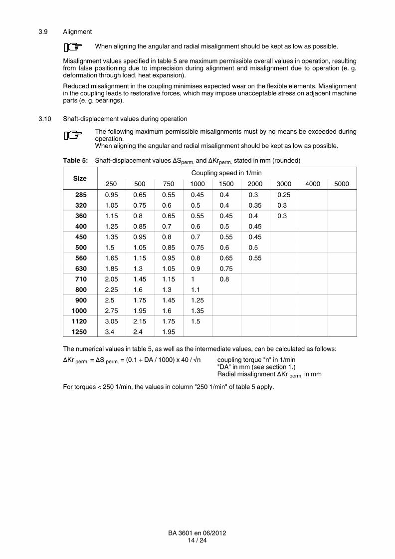
3.9 Alignment
When aligning the angular and radial misalignment should be kept as low as possible.
Misalignment values specified in table 5 are maximum permissible overall values in operation, resultingfrom false positioning due to imprecision during alignment and misalignment due to operation (e. g.deformation through load, heat expansion).
Reduced misalignment in the coupling minimises expected wear on the flexible elements. Misalignmentin the coupling leads to restorative forces, which may impose unacceptable stress on adjacent machineparts (e. g. bearings).
3.10 Shaft-displacement values during operation
The following maximum permissible misalignments must by no means be exceeded duringoperation.When aligning the angular and radial misalignment should be kept as low as possible.
Table 5: Shaft-displacement values ΔSperm. and ΔKrperm. stated in mm (rounded)
SizeCoupling speed in 1/min
250 500 750 1000 1500 2000 3000 4000 5000
285 0.95 0.65 0.55 0.45 0.4 0.3 0.25
320 1.05 0.75 0.6 0.5 0.4 0.35 0.3
360 1.15 0.8 0.65 0.55 0.45 0.4 0.3
400 1.25 0.85 0.7 0.6 0.5 0.45
450 1.35 0.95 0.8 0.7 0.55 0.45
500 1.5 1.05 0.85 0.75 0.6 0.5
560 1.65 1.15 0.95 0.8 0.65 0.55
630 1.85 1.3 1.05 0.9 0.75
710 2.05 1.45 1.15 1 0.8
800 2.25 1.6 1.3 1.1
900 2.5 1.75 1.45 1.25
1000 2.75 1.95 1.6 1.35
1120 3.05 2.15 1.75 1.5
1250 3.4 2.4 1.95
The numerical values in table 5, as well as the intermediate values, can be calculated as follows:
ΔKr perm. = ΔS perm. = (0.1 + DA / 1000) x 40 / √n coupling torque "n" in 1/min"DA" in mm (see section 1.)Radial misalignment ΔKr perm. in mm
For torques < 250 1/min, the values in column "250 1/min" of table 5 apply.

15 / 24BA 3601 en 06/2012
3.11 Setting the axial backlash
The axial backlash limitation on the RUPEX coupling must in every case be less than the determined axialbacklash of the electric motor.
Using the set screws (33; 34), set the axial backlash of the RUPEX coupling to about half the determinedmotor axial backlash. The coupling backlash must be within the permissible values for "S".
Example:
Axial backlash of the motor = 8 mm
Axial backlash of the coupling = 4 mm
Axial backlash to be set for each coupling part (dimension *) = 2 mm
As the mid-point of the rotor's axial backlash need not coincidewith the magnetic centre of the motor, many electric motors havea mark on the shaft. When this identification mark is aligned withthe outer surface of the bearing cover, the magnetic centre of therotor is obtained.The magnetic centre must be determined by means of a test runif the motors do not have this identification marking.
In this operating position the set axial backlash on the RUPEXcoupling (dimension *) must be identical on both sides to preventaxial forces affecting the machine bearings. After completedsetting, the lock nuts (35) must be tightened.
The set axial backlash must be sufficient to enable the RUPEX coupling to compensatefor the resulting angular deviation.
*
*
16 / 24BA 3601 en 06/2012
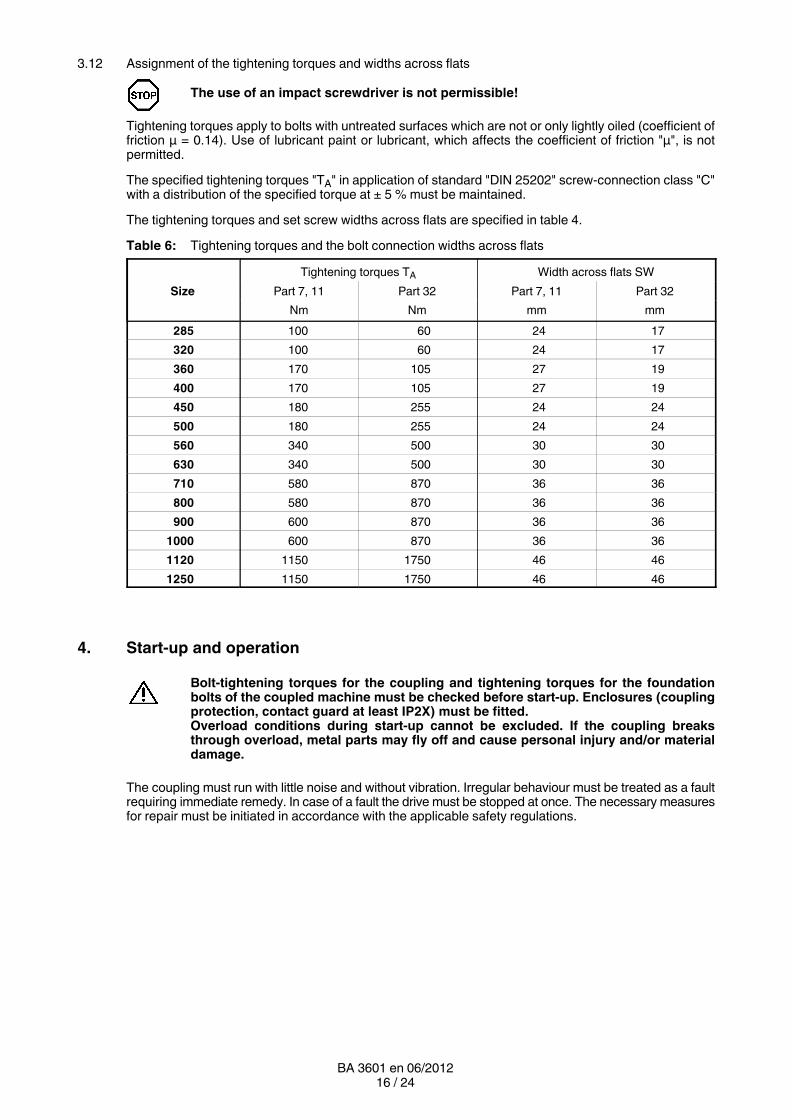
3.12 Assignment of the tightening torques and widths across flats
The use of an impact screwdriver is not permissible!
Tightening torques apply to bolts with untreated surfaces which are not or only lightly oiled (coefficient offriction μ = 0.14). Use of lubricant paint or lubricant, which affects the coefficient of friction "μ", is notpermitted.
The specified tightening torques "TA" in application of standard "DIN 25202" screw-connection class "C"with a distribution of the specified torque at ± 5 % must be maintained.
The tightening torques and set screw widths across flats are specified in table 4.
Table 6: Tightening torques and the bolt connection widths across flats
Size
Tightening torques TA Width across flats SW
Part 7, 11 Part 32 Part 7, 11 Part 32
Nm Nm mm mm
285 100 60 24 17
320 100 60 24 17
360 170 105 27 19
400 170 105 27 19
450 180 255 24 24
500 180 255 24 24
560 340 500 30 30
630 340 500 30 30
710 580 870 36 36
800 580 870 36 36
900 600 870 36 36
1000 600 870 36 36
1120 1150 1750 46 46
1250 1150 1750 46 46
4. Start-up and operation
Bolt-tightening torques for the coupling and tightening torques for the foundationbolts of the coupled machine must be checked before start-up. Enclosures (couplingprotection, contact guard at least IP2X) must be fitted.Overload conditions during start-up cannot be excluded. If the coupling breaksthrough overload, metal parts may fly off and cause personal injury and/or materialdamage.
The coupling must run with little noise and without vibration. Irregular behaviour must be treated as a faultrequiring immediate remedy. In case of a fault the drive must be stopped at once. The necessary measuresfor repair must be initiated in accordance with the applicable safety regulations.
17 / 24BA 3601 en 06/2012
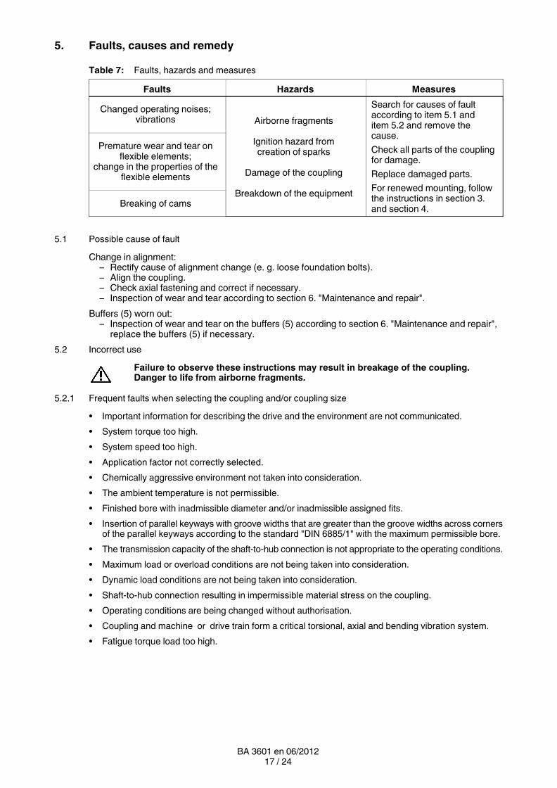
5. Faults, causes and remedy
Table 7: Faults, hazards and measures
Faults Hazards Measures
Changed operating noises;vibrations Airborne fragments
Ignition hazard fromcreation of sparks
Damage of the coupling
Breakdown of the equipment
Search for causes of faultaccording to item 5.1 anditem 5.2 and remove thecause.
Check all parts of the couplingfor damage.
Replace damaged parts.
For renewed mounting, followthe instructions in section 3.and section 4.
Premature wear and tear onflexible elements;
change in the properties of theflexible elements
Breaking of cams
5.1 Possible cause of fault
Change in alignment:– Rectify cause of alignment change (e. g. loose foundation bolts).– Align the coupling.– Check axial fastening and correct if necessary.– Inspection of wear and tear according to section 6. "Maintenance and repair".
Buffers (5) worn out:– Inspection of wear and tear on the buffers (5) according to section 6. "Maintenance and repair",
replace the buffers (5) if necessary.
5.2 Incorrect use
Failure to observe these instructions may result in breakage of the coupling.Danger to life from airborne fragments.
5.2.1 Frequent faults when selecting the coupling and/or coupling size
• Important information for describing the drive and the environment are not communicated.
• System torque too high.
• System speed too high.
• Application factor not correctly selected.
• Chemically aggressive environment not taken into consideration.
• The ambient temperature is not permissible.
• Finished bore with inadmissible diameter and/or inadmissible assigned fits.
• Insertion of parallel keyways with groove widths that are greater than the groove widths across cornersof the parallel keyways according to the standard "DIN 6885/1" with the maximum permissible bore.
• The transmission capacity of the shaft-to-hub connection is not appropriate to the operating conditions.
• Maximum load or overload conditions are not being taken into consideration.
• Dynamic load conditions are not being taken into consideration.
• Shaft-to-hub connection resulting in impermissible material stress on the coupling.
• Operating conditions are being changed without authorisation.
• Coupling and machine or drive train form a critical torsional, axial and bending vibration system.
• Fatigue torque load too high.
18 / 24BA 3601 en 06/2012
5.2.2 Frequent faults when fitting the coupling
• Components with transport or other damage are being fitted.
• When fitting coupling parts in a heated condition, already fitted RUPEX buffers (5) are beingexcessively heated.
• The shaft diameter is beyond the specified tolerance range.
• Coupling parts are mixed up, i. e. their attribution to the specified shaft is incorrect.
• Specified axial fastenings are not fitted.
• Specified tightening torques are not being adhered to.
• Bolts are fitted in dry or greased condition.
• Flange surfaces of screwed connections have not been cleaned.
• Alignment and/or shaft-misalignment values do not match the specifications in the instructions manual.
• The coupled machines are not correctly fastened to the foundation, so that a shifting of the machinese. g. due to loosening of the foundation-screw connection is causing excessive displacement of thecoupling parts.
• The coupled machines are not sufficiently earthed.
• RUPEX buffers are not fitted.
• The coupling guard used is not suitable.
• Markings of balancing groups are not observed.
5.2.3 Frequent faults in maintenance
• Maintenance intervals are not being adhered to.
• No genuine RUPEX spare parts are being used.
• Old or damaged RUPEX spare parts are being used.
• Different N-EUPEX buffers (5) are being used.
• Leakage in the vicinity of the coupling is not being identified and as a result chemically aggressivemedia are damaging the coupling.
• Fault indications (noise, vibrations, etc.) are not being observed.
• Specified tightening torques are not being adhered to.
• Alignment and/or shaft-misalignment values do not match the specifications in the instructions manual.

19 / 24BA 3601 en 06/2012
6. Maintenance and repair
6.1 Maintenance interval
The torsional backlash between the two coupling parts must be checked after threemonths, and thereafter at least once a year.
The buffers (5) must be replaced, when the torsional backlash exceeds the value stated in table 8.
Δ S
V
Fig. 5: Wear mark
Table 8: Wear mark for the torsional clearance
Size285 360 450 560 710 900 1120
320 400 500 630 800 1000 1250
Wear mark ΔSV inmm
6.0 7.0 8.5 10.0 12.0 13.5 15.0
Failure to observe these instructions may result in breakage of the coupling.Danger to life from airborne fragments.
6.2 Replacement of wearing parts
Remove screws (32) and place restraining ring (31) on the coupling part (1).
Deinstall bolts (4) with buffers (5) after loosening and removing the hexagon nuts (7) through the bufferbores (up to coupling size 400).
Deinstall bolts (4) with buffers (5) after loosening and removing the hexagon screws (11) and disks (8)through the buffer bores (starting from coupling size 450).
Deinstall buffers (5) after removing the circlip (12) and the disk (6) through the buffer bores (starting fromcoupling size 710 without deinstallation of the bolts).
Pull off the buffers (5) and carefully clean the bolts (4) and fitting holes.
Replace buffers (5) by sets. Only identical buffers (5) may be used.
After replacing the buffers (5), the assembly follows in reverse order. In the process, secure thescrews (11) with thread locking "medium firm" (e. g. Loctite 243). Replace the self-locking hexagonnuts (7) by new hexagon nuts (7) of same quality.
For renewed mounting, follow the instructions in section 3. "Fitting" and section 4. "Start-up and operation".

20 / 24BA 3601 en 06/2012
6.2.1 Extract bolts for coupling sizes 450 to 1250 using the demounting box
For demounting of the bolts, Siemens offers a hydraulic extracting device, which can be provided onrequest.
Observe instruction BA 3600.1 "Demounting box for extraction of RUPEX bolts".
6.2.2 Extract bolts for coupling sizes 450 to 1250 with grease
Separate the coupling halves (1; 2) or switch to no load. Starting from coupling size 710 upwards thelocking rings (12) and disks (6) can be removed and the buffers (5) pulled off the bolts (4) if a separationof the coupling halves (1; 2) is not possible.
Unscrew bolt (11) and remove disk (8). Completely remove Loctite residue from the tapped hole.
The thread bore of the RUPEX bolt must be filled to 90 % with common retail machine grease (e. g. FuchsRenolit H443-HD-88).
Wrap screw (11) in Teflon tape or Teflon sealing rope and screw in manually with the disk (8) setunderneath into the bolt (4) with 2-3 threads.
Wear protective glasses.
For axial fastening it is absolutely necessary to use a disk (8) underneath the screw(11).
Danger of being jammed in by the sudden movement of the screw (11), disk (8) andsudden release of the bolt (4).Sudden release of the bolt can be heard as a loud noise.
Slowly continue tightening the screw (11) into the thread using a screwdriver. In this way, the grease ispressed through the cross-bore between the bolt and bolt bore in the coupling part (1; 2). In order for thegrease to distribute evenly on the bolt (4), be sure to tighten slowly. If sufficient pressure cannot be builtup, use a longer screw (at least strength class 8.8) or refill grease if necessary.No grease may dissipate; otherwise the screw (11) must be newly sealed.
The extraction process is finished as soon as the bolt (4) is released from the bore.
Demount all the bolts (4) one after the other in this way.
When reusing the old bolts (4), clean them thoroughly. No grease or Loctite residues must be left in thethreaded bores/cross-bores of the bolts (4).
Apply just a small quantity of Loctite to the screw (11), otherwise there is a risk that the Loctite might sealthe cross-bore.
For renewed mounting, follow the instructions in section 3. "Fitting" and section 4. "Start-up and operation".
6.3 Demounting the coupling parts in case of shaft-hub connection with parallel key
Remove screws (32) and place restraining ring (31) onto the coupling part (1).
Move the coupled machines apart.
Remove the axial fastening (set screw, end plate). Mount suitable detaching device. Using a burner, heatcoupling part (1; 2) along its length and above the parallel keyway (max. + 80 °C). When heating upobserve the temperature range of the buffers (5) (see table 1), if necessary demount the buffers (5).
Pull off coupling part (1; 2). Examine the hub bore and the shaft for damage, and protect against rust.Replace damaged parts.
For renewed mounting, follow the instructions in section 3. "Fitting" and section 4. "Start-up and operation".
21 / 24BA 3601 en 06/2012
6.4 Demounting of coupling parts with a cylindrical and tapered interference fit set up for removal byoil-hydraulic shrinking-off
Remove screws (32) and place restraining ring (31) onto the coupling part (1). Pull the coupled machinesapart and demount the buffers (5).
For demounting the following tools are needed:
• For each oil channel (their total number can be found in the dimensioned drawing), one oil pump withpressure gauge (at least 2 500 bar) or a motor pump with equivalent number of connections to be closedindependently.For coupling parts (1; 2) with stepped bore, a motor-driven pump must be connected to the oil channellocated at the point of transition from the smaller to the larger bore, as a large quantity of oil per unit oftime is needed here.
• Suitable connections and pipes.
• 1 detaching device or retaining plate with retaining screws or threaded spindles with nuts (material ofscrews and spindles min. 10.9, material of nuts identical to that of the screws).
• 1 hydraulic cylinder with oil pump. Note displacement and pressure of the hydraulic cylinder (for axialforce, consult Siemens or refer to the dimensioned drawing).
Observe the manufacturer information for the handling of extraction or detachingdevices and pumps.
Mount the detaching device.
Secure coupling part (1; 2) and detaching device, using suitable lifting equipment.
Mount an axial restraint for coupling parts (1; 2) with tapered bore to prevent suddenrelease of the coupling part (1; 2).
Remove screw plugs (101; 201) from the oil channels. Ventilate one oil pump and connect it to the middleoil channel.
Then, pressurise the pump with the pressure specified in the dimensioned drawing until oil dissipates fromthe adjacent connections or the front faces.
The max. pressure specified on the dimensioned drawing must not be exceeded.During the entire operation the pressure must be maintained at a constant level on allthe oil channels to which pressure is applied.
Ventilate the next oil pump and connect it to the adjacent oil channel, and pressurise with the pressurespecified in the dimensioned drawing until oil dissipates from the adjacent connections or the front faces.
If oil dissipates to the extent that pressure cannot be maintained while pressure is being applied, a thickeroil must be provided.
Only pressurise the hydraulic cylinder when oil dissipates on both front faces as a closed oil ring, so thatthe coupling part (1; 2) can slide swiftly from the shaft.
The oil must be completely collected and disposed of in accordance with valid regulations.
Note stroke of hydraulic cylinder. If re-adjustment is necessary, the end face of thehydraulic cylinder must stop between 2 oil channels.
After detaching, the oil pumps and the detaching device must be demounted from the coupling part (1; 2).
Examine the hub bore and the shaft for damage, and protect against rust. Replace damaged parts.
For renewed mounting, follow the instructions in section 3. "Fitting" and section 4. "Start-up and operation".

22 / 24BA 3601 en 06/2012
7. Stocking spare parts
7.1 Spare parts
For ordering spare parts state the following data, as far as possible:
• Siemens order number and position
• Siemens drawing number
• Coupling type and coupling size
• Part number (see spare-parts list)
• Bore, bore tolerance, groove and balancing as well as particular characteristics, such asflange-connection dimensions, intermediate-shaft length, brake-drum dimensions.
• Any special details, e. g. temperature, electrically insulating.
Table 9: Spare-parts list
Partnumber
Designation
1 Coupling part 1
2 Coupling part 2
4 Bolt
5 Buffer
6 Washer
7 Hexagon nut, self-locking
8 Washer
11 Hexagon-head bolt
12 Locking ring
30 Bolt spec.
31 Retaining ring
32 Bolt
33 Set screw
34 Set screw
35 Nut
100 Set screw ISO 4028
101 Screw plug 1)
200 Set screw ISO 4028
201 Screw plug 1)
1) The plug screws (101; 201; see figure 6) are only used for the oil-hydraulic interference fit (seeitem 3.6).
101201
Fig. 6: Screw plug

23 / 24BA 3601 en 06/2012
5 114 86125 118645 76
2) 3) 4)
4
1)
35 33 34 35
1 32 31 30 2
Fig. 7: Spare-parts drawing
1) Types RWN and RWS with axial backlash limitation
2) Bolt connections for sizes 285 to 400
3) Bolt connections for sizes 450 to 630
4) Bolt connections for sizes 710 to 1250
Up to size 360 the buffers are arranged on one side in the coupling part 1. Starting from size 400the buffers are arranged alternately in coupling part 1 and 2.

Siemens AGIndustry SectorMechanical DrivesAlfred-Flender-Straße 7746395 BocholtGERMANY
www.siemens.com/drivetechnologies
Subject to modifications
© Siemens AG 2012
Further Information:
"FLENDER gear units" on the Internetwww.siemens.com/gearunits
"FLENDER couplings" on the Internetwww.siemens.com/couplings
Service & Support:http://support.automation.siemens.com/WW/view/en/10803928/133300
Lubricants:http://support.automation.siemens.com/WW/view/en/42961591/133000