Flatpack 2 Smartpack Monitoring
20
350003.013 User’s Guide Monitoring and Control Unit Flatpack2 DC Power Supply Systems
Transcript of Flatpack 2 Smartpack Monitoring

35
0003
.013
User’s Guide
Monitoring and Control Unit Flatpack2 DC Power Supply Systems

1 Welcome
2 User’s Guide Smartpack Monitoring & Ctrl Unit, Art. 350003.013, v2-2005-06
Information in this document is subject to change without notice and does not represent a commitment on the part of Eltek Energy. No part of this document may be reproduced or transmitted in any form or by any means — electronic or mechanical, including photocopying and recording — for any purpose without the explicit written permission of Eltek Energy.
Copyright ©: Eltek Energy, Norway 2005
Certificate no: 900005E Certificate no: 900005Q
Head Office: Eltek Energy P.O. Box 2340 Strømsø N-3003 DRAMMEN Norway
Phone: (+47) 32 20 32 00 Fax: (+47) 32 20 32 10 E-Mail: [email protected] Internet: http://www.eltekenergy.com
350003.013 Issue 2, 2005 Jun Published 2005-06-07 Mfm
1 Welcome
User’s Guide Smartpack Monitoring & Ctrl Unit, Art. 350003.013, v2-2005-06 3
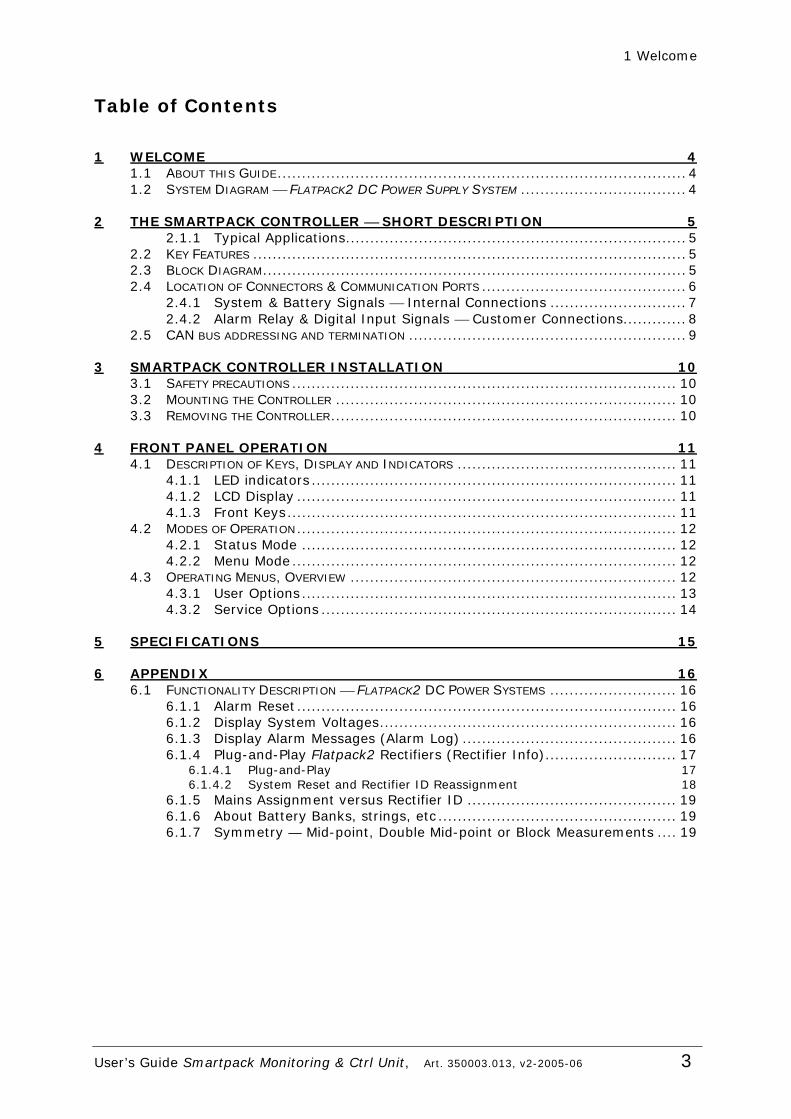
Table of Contents
1 WELCOME 4 1.1 ABOUT THIS GUIDE.................................................................................... 4 1.2 SYSTEM DIAGRAM ⎯ FLATPACK2 DC POWER SUPPLY SYSTEM .................................. 4
2 THE SMARTPACK CONTROLLER ⎯ SHORT DESCRIPTION 5 2.1.1 Typical Applications...................................................................... 5
2.2 KEY FEATURES ......................................................................................... 5 2.3 BLOCK DIAGRAM....................................................................................... 5 2.4 LOCATION OF CONNECTORS & COMMUNICATION PORTS .......................................... 6
2.4.1 System & Battery Signals ⎯ Internal Connections ............................ 7 2.4.2 Alarm Relay & Digital Input Signals ⎯ Customer Connections............. 8
2.5 CAN BUS ADDRESSING AND TERMINATION ......................................................... 9
3 SMARTPACK CONTROLLER INSTALLATION 10 3.1 SAFETY PRECAUTIONS ............................................................................... 10 3.2 MOUNTING THE CONTROLLER ...................................................................... 10 3.3 REMOVING THE CONTROLLER....................................................................... 10
4 FRONT PANEL OPERATION 11 4.1 DESCRIPTION OF KEYS, DISPLAY AND INDICATORS ............................................. 11
4.1.1 LED indicators ........................................................................... 11 4.1.2 LCD Display .............................................................................. 11 4.1.3 Front Keys................................................................................ 11
4.2 MODES OF OPERATION.............................................................................. 12 4.2.1 Status Mode ............................................................................. 12 4.2.2 Menu Mode............................................................................... 12
4.3 OPERATING MENUS, OVERVIEW ................................................................... 12 4.3.1 User Options............................................................................. 13 4.3.2 Service Options ......................................................................... 14
5 SPECIFICATIONS 15
6 APPENDIX 16 6.1 FUNCTIONALITY DESCRIPTION ⎯ FLATPACK2 DC POWER SYSTEMS .......................... 16
6.1.1 Alarm Reset.............................................................................. 16 6.1.2 Display System Voltages............................................................. 16 6.1.3 Display Alarm Messages (Alarm Log) ............................................ 16 6.1.4 Plug-and-Play Flatpack2 Rectifiers (Rectifier Info)........................... 17
6.1.4.1 Plug-and-Play 17 6.1.4.2 System Reset and Rectifier ID Reassignment 18
6.1.5 Mains Assignment versus Rectifier ID ........................................... 19 6.1.6 About Battery Banks, strings, etc ................................................. 19 6.1.7 Symmetry — Mid-point, Double Mid-point or Block Measurements .... 19
1 Welcome
4 User’s Guide Smartpack Monitoring & Ctrl Unit, Art. 350003.013, v2-2005-06
1 Welcome Congratulations on your purchase of the powerful Flatpack2 DC power supply system, which uses the new Smartpack controller ⎯ a powerful and cost-effective module developed for monitoring and controlling your DC power system.
1.1 About this Guide This booklet provides users of Flatpack2 DC power systems with the required information for operating the system using the Smartpack’s front panel. The booklet also describes the Smartpack controller’s building blocks, external connections and specifications. Take a look at the table of contents to familiarise yourself with this booklet. We have also emphasised the use of images and graphics to make the book easy and interesting to read. Read also the general and site specific documentation that was delivered with your Flatpack2 DC power system.
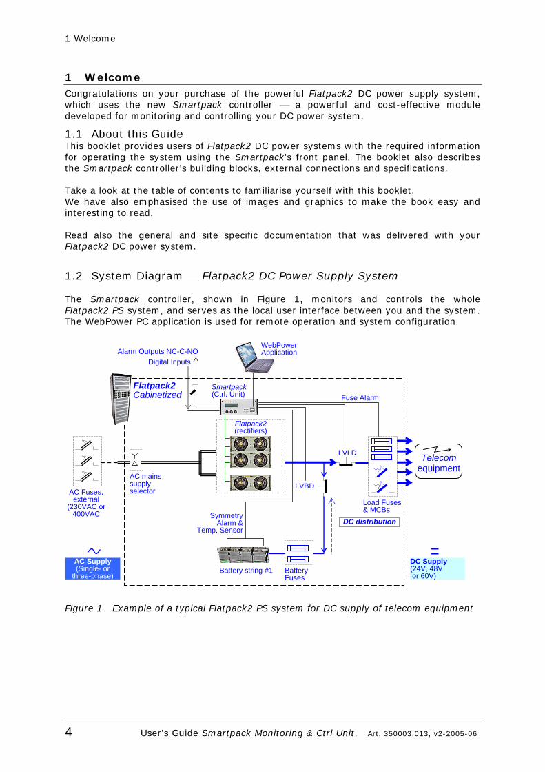
1.2 System Diagram ⎯ Flatpack2 DC Power Supply System
The Smartpack controller, shown in Figure 1, monitors and controls the whole Flatpack2 PS system, and serves as the local user interface between you and the system. The WebPower PC application is used for remote operation and system configuration.
Figure 1 Example of a typical Flatpack2 PS system for DC supply of telecom equipment
Flatpack2 Cabinetized
Battery string #1
AC mains supply selector
SymmetryAlarm &
Temp. Sensor
LVLD
LVBD
AC Supply (Single- or
three-phase)
Fuse Alarm
DC Supply (24V, 48V or 60V)
AC Fuses, external
(230VAC or 400VAC
Telecomequipment
Alarm Outputs NC-C-NO Digital Inputs
DC distribution
BatteryFuses
Load Fuses & MCBs
Smartpack (Ctrl. Unit)
Flatpack2(rectifiers)
WebPowerApplication
2 The Smartpack Controller ( Short Description
User’s Guide Smartpack Monitoring & Ctrl Unit, Art. 350003.013, v2-2005-06 5
2 The Smartpack Controller ⎯ Short Description The Smartpack module is a monitoring and control unit that serves as the vital nerve center of the Flatpack2 DC power plant, representing the main interface between you and the system. The module’s elegant front panel enables both local and remote system monitoring and control, using three front keys and
LCD-display, and USB- or RS-232 interface, as well as via modem, Ethernet, Web and SNMP. See also chapter “Specifications”, on page 15.
2.1.1 Typical Applications The Smartpack controller employs CAN bus communication with the Flatpack2 rectifiers ⎯ and other bus-connected Smartpack controllers in the system ⎯ thus enabling flexible expansion of system functionality and number of measuring points. System components can be set up and upgraded to meet the demand of any tailor-made power solution.
2.2 Key Features Front panel LCD and buttons for on-site service without PC. USB- or RS-232 interface for PC connection locally or remote monitoring and
control via modem, Ethernet, web or SNMP. 6 user programmable relay outputs for traditional remote monitoring 6 user programmable inputs for monitoring of other equipment on site Battery monitoring and testing without site attendance Temperature compensated charging for increased battery lifetime Battery lifetime indication Password protected operator access levels Alarm/event log with time and date Windows-based PC communication software
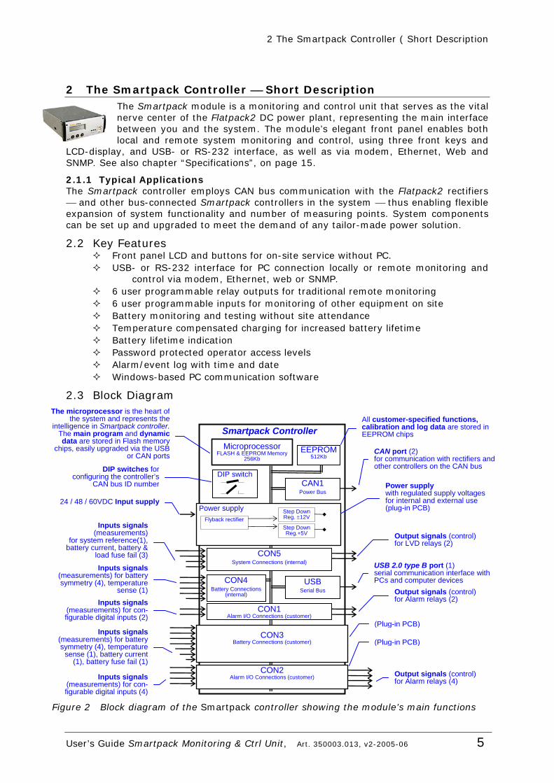
2.3 Block Diagram
Figure 2 Block diagram of the Smartpack controller showing the module’s main functions
Smartpack Controller Microprocessor
FLASH & EEPROM Memory 256Kb
EEPROM512Kb
CAN1 Power Bus
The microprocessor is the heart of the system and represents the
intelligence in Smartpack controller.The main program and dynamic data are stored in Flash memory
chips, easily upgraded via the USBor CAN ports CAN port (2)
for communication with rectifiers and other controllers on the CAN bus DIP switches for
configuring the controller’s CAN bus ID number
24 / 48 / 60VDC Input supply
Power supply with regulated supply voltages for internal and external use (plug-in PCB)
All customer-specified functions, calibration and log data are stored in EEPROM chips
DIP switch
Power supply Flyback rectifier
Step Down Reg.+5V
Step Down Reg. ±12V
CON5 System Connections (internal)
Inputs signals (measurements)
for system reference(1), battery current, battery &
load fuse fail (3)
Output signals (control)for LVD relays (2)
CON4 Battery Connections
(internal)
Inputs signals (measurements) for battery symmetry (4), temperature
sense (1)
CON1 Alarm I/O Connections (customer)
Inputs signals (measurements) for con-figurable digital inputs (2)
Output signals (control)for Alarm relays (2)
CON3 Battery Connections (customer)
Inputs signals (measurements) for battery symmetry (4), temperature
sense (1), battery current (1), battery fuse fail (1)
CON2 Alarm I/O Connections (customer) Output signals (control)
for Alarm relays (4)
(Plug-in PCB)
(Plug-in PCB)
Inputs signals (measurements) for con-figurable digital inputs (4)
USB Serial Bus
USB 2.0 type B port (1) serial communication interface with PCs and computer devices

2 The Smartpack Controller ( Short Description
6 User’s Guide Smartpack Monitoring & Ctrl Unit, Art. 350003.013, v2-2005-06
2.4 Location of Connectors & Communication Ports
You can easily connect the Smartpack controller to a PC, plugging a standard USB A-B cable to the USB port on the front of the controller and to any available USB port on the computer. The Smartpack controller is configured from factory ⎯ via DIP switched on the side ⎯ with an ID number for CAN bus communication. On the controller’s rear ⎯see Figure 4 ⎯ you find two identical RJ45 CAN ports (for incoming and outgoing CAT5 twisted-pair cables) to connect the controller to the CAN bus. See also chapter “CAN bus addressing and termination”, on page 9.
Figure 3 Front access USB port, and DIP switches for ID configuration on the side.
The Smartpack controller’s inputs and outputs ⎯ for monitoring and controlling the system, the batteries, alarm relays and configurable digital ⎯ are located in the rear the controller.
Figure 4 Rear plug connections on the Smartpack controller
USB 2.0 type B port(PC connection)
DIP switches (CAN ID number)
Alarm I/0 Connections ⎯ Extended D-sub, 26 pins, female (Customer)
CAN port (2)RJ45, 8 pins connector(Internal and customer)
Battery Connections ⎯ ExtendedD-sub, 15 pins, male (Internal)
Battery ConnectionsD-sub, 15 pins, male (Internal)
System ConnectionsD-sub, 15 pins, female (Internal)
Alarm I/0 Connections Mini power connector, 10 pins, male (Customer)
2 The Smartpack Controller ( Short Description
User’s Guide Smartpack Monitoring & Ctrl Unit, Art. 350003.013, v2-2005-06 7
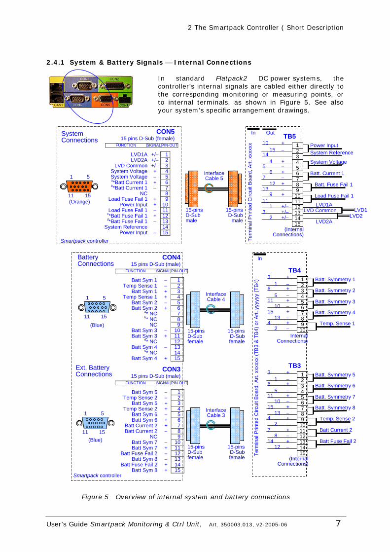
2.4.1 System & Battery Signals ⎯ Internal Connections
In standard Flatpack2 DC power systems, the controller’s internal signals are cabled either directly to the corresponding monitoring or measuring points, or to internal terminals, as shown in Figure 5. See also your system’s specific arrangement drawings.
Figure 5 Overview of internal system and battery connections
+
4 3 2 1
5
9 8 7 6
10
14 13 12 11
15
TB5 Power Input
− + − + − + − + − +/− +/− +/−
1015
144
56
712
139
111
32
Batt. Fuse Fail 1
Load Fuse Fail 1
System Voltage
System Reference
Batt. Current 1
(Internal Connections)
LVD1ALVD Common
LVD2A
LVD1LVD2
OutIn
Term
inal
Prin
ted
Circ
uit B
oard
, Art.
xxx
xxx
15-pinsD-Sub male
InterfaceCable 5
15-pinsD-Sub
male
System Connections
CON515 pins D-Sub (female)
LVD1A +/− 1LVD2A +/− 2
LVD Common +/− 3System Voltage + 4System Voltage − 5a*Batt Current 1 + 6b*Batt Current 1 − 7
NC 8Load Fuse Fail 1 + 9
Power Input + 10Load Fuse Fail 1 − 11
c*Batt Fuse Fail 1 + 12d*Batt Fuse Fail 1 − 13
System Reference 14Power Input − 15
FUNCTION SIGNAL PIN-OUT
Smartpack controller
1 5
11 15 (Orange)
15-pinsD-Sub female
InterfaceCable 3
15-pinsD-Subfemale
Smartpack controller
Ext. Battery Connections
CON315 pins D-Sub (male)
Batt Sym 5 − 1Temp Sense 2 − 2
Batt Sym 5 + 3 Temp Sense 2 + 4
Batt Sym 6 − 5 Batt Sym 6 + 6
Batt Current 2 + 7 Batt Current 2 − 8
NC 9 Batt Sym 7 − 10 Batt Sym 7 + 11
Batt Fuse Fail 2 − 12 Batt Sym 8 − 13
Batt Fuse Fail 2 + 14 Batt Sym 8 + 15
FUNCTION SIGNALPIN-OUT
(Blue)
1 5
11 15
FUNCTION SIGNALPIN-OUT
CON415 pins D-Sub (male)
Batt Sym 1 − 1Temp Sense 1 − 2
Batt Sym 1 + 3 Temp Sense 1 + 4
Batt Sym 2 − 5 Batt Sym 2 + 6
a* NC 7 b* NC 8
NC 9 Batt Sym 3 − 10 Batt Sym 3 + 11
d* NC 12 Batt Sym 4 − 13
c* NC 14 Batt Sym 4 + 15
Battery Connections
(Blue)
1 5
11 15
InTe
rmin
al P
rinte
d C
ircui
t Boa
rd, A
rt. x
xxxx
x (T
B3
& T
B4)
or A
rt. y
yyyy
y (T
B4)
+
4 3 2 1
5
9 8 7 6
10
14 13 12 11
15
TB3 Batt. Symmetry 5
− + − + − + − + − + − + −
31
65
1110
1513
42
78
1412
Temp. Sense 2
Batt Current 2
Batt Fuse Fail 2
Batt. Symmetry 7
Batt. Symmetry 6
Batt. Symmetry 8
(Internal Connections)
TB4 Batt. Symmetry 1
Temp. Sense 1
Batt. Symmetry 3
Batt. Symmetry 2
Batt. Symmetry 4
+
4 3 2 1
5
9 8 7 6
10
− + − + − + − + −
31
65
1110
1513
42
Internal Connections)
15-pinsD-Sub female
InterfaceCable 4
15-pinsD-Subfemale
2 The Smartpack Controller ( Short Description
8 User’s Guide Smartpack Monitoring & Ctrl Unit, Art. 350003.013, v2-2005-06
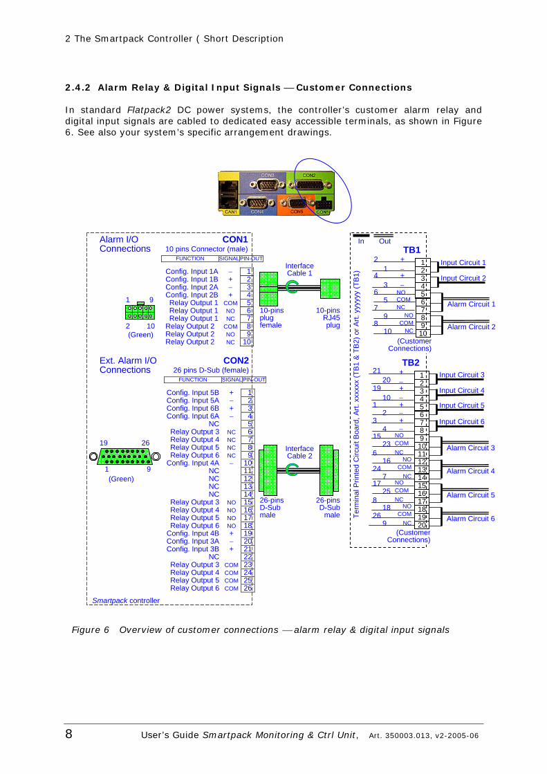
2.4.2 Alarm Relay & Digital Input Signals ⎯ Customer Connections
In standard Flatpack2 DC power systems, the controller’s customer alarm relay and digital input signals are cabled to dedicated easy accessible terminals, as shown in Figure 6. See also your system’s specific arrangement drawings.
Figure 6 Overview of customer connections ⎯ alarm relay & digital input signals
4 3 2 1
5
9 8 7 6
10
TB1
(Customer Connections)
Input Circuit 1
Input Circuit 2
Alarm Circuit 1
Alarm Circuit 2
Out In
+ − + −
NO
21
43
65
79
810
COM NC
NOCOM
NC
Term
inal
Prin
ted
Circ
uit B
oard
, Art.
xxx
xxx
(TB
1 &
TB
2) o
r Art.
yyy
yyy
(TB
1)
Input Circuit 3
Alarm Circuit 3
Input Circuit 4
Input Circuit 5
Input Circuit 6
Alarm Circuit 4
Alarm Circuit 5
Alarm Circuit 6
+
4 3 2 1
5
9 8 7 6
10
14 13 12 11
15
TB2
− + − + − + −
2120
1910
12
34
1523
616
247
(CustomerConnections)
16 17 18 19 20
NO COM NC
NO COM
NC 17
25 8
NO COM NC
18 26
9
NO COM
NC
10-pinsplug female
InterfaceCable 1
10-pinsRJ45plug
26-pinsD-Sub male
InterfaceCable 2
26-pinsD-Sub
male
Alarm I/O Connections
1 9
2 10 (Green)
Smartpack controller
Ext. Alarm I/O Connections
CON226 pins D-Sub (female)
Config. Input 5B + 1Config. Input 5A − 2Config. Input 6B + 3Config. Input 6A − 4
NC 5Relay Output 3 NC 6Relay Output 4 NC 7Relay Output 5 NC 8Relay Output 6 NC 9
Config. Input 4A − 10NC 11NC 12NC 13NC 14
Relay Output 3 NO 15Relay Output 4 NO 16Relay Output 5 NO 17Relay Output 6 NO 18
Config. Input 4B + 19Config. Input 3A − 20Config. Input 3B + 21
NC 22Relay Output 3 COM 23Relay Output 4 COM 24Relay Output 5 COM 25Relay Output 6 COM 26
FUNCTION SIGNALPIN-OUT
19 26
1 9 (Green)
CON110 pins Connector (male)
Config. Input 1A − 1Config. Input 1B + 2Config. Input 2A − 3Config. Input 2B + 4Relay Output 1 COM 5Relay Output 1 NO 6Relay Output 1 NC 7
Relay Output 2 COM 8Relay Output 2 NO 9Relay Output 2 NC 10
FUNCTION SIGNALPIN-OUT
2 The Smartpack Controller ( Short Description
User’s Guide Smartpack Monitoring & Ctrl Unit, Art. 350003.013, v2-2005-06 9
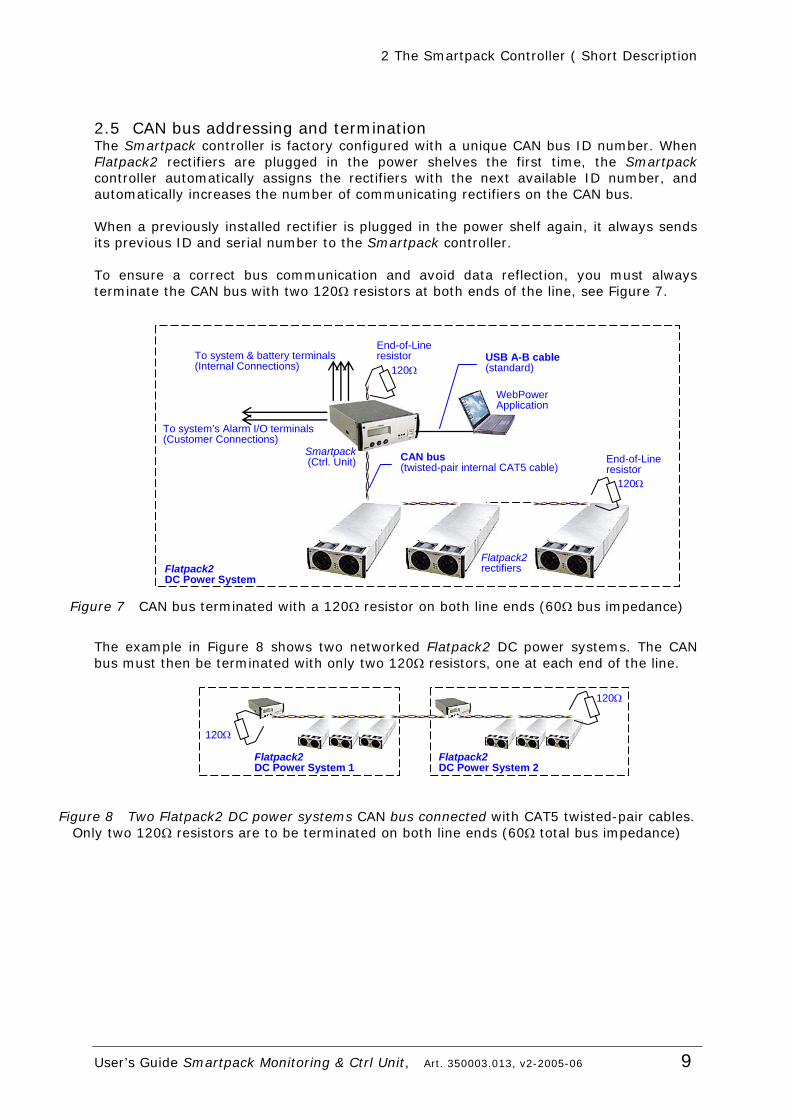
2.5 CAN bus addressing and termination The Smartpack controller is factory configured with a unique CAN bus ID number. When Flatpack2 rectifiers are plugged in the power shelves the first time, the Smartpack controller automatically assigns the rectifiers with the next available ID number, and automatically increases the number of communicating rectifiers on the CAN bus. When a previously installed rectifier is plugged in the power shelf again, it always sends its previous ID and serial number to the Smartpack controller. To ensure a correct bus communication and avoid data reflection, you must always terminate the CAN bus with two 120Ω resistors at both ends of the line, see Figure 7.
Figure 7 CAN bus terminated with a 120Ω resistor on both line ends (60Ω bus impedance)
The example in Figure 8 shows two networked Flatpack2 DC power systems. The CAN bus must then be terminated with only two 120Ω resistors, one at each end of the line.
Figure 8 Two Flatpack2 DC power systems CAN bus connected with CAT5 twisted-pair cables. Only two 120Ω resistors are to be terminated on both line ends (60Ω total bus impedance)
120Ω
Flatpack2DC Power System 2
120Ω
Flatpack2 DC Power System 1
WebPowerApplication
End-of-Lineresistor
Flatpack2rectifiers
To system’s Alarm I/O terminals (Customer Connections)
To system & battery terminals (Internal Connections)
USB A-B cable (standard)
CAN bus(twisted-pair internal CAT5 cable)
120Ω
120Ω
End-of-Lineresistor
Flatpack2 DC Power System
Smartpack (Ctrl. Unit)
3 Smartpack Controller Installation
10 User’s Guide Smartpack Monitoring & Ctrl Unit, Art. 350003.013, v2-2005-06
3 Smartpack Controller Installation
3.1 Safety precautions The equipment described in this manual must only be operated by Eltek
Energy personnel or by persons who have attended a suitable Eltek Energy training course
The equipment represents an energy hazard and failure to observe this could cause terminal injury and invalidate our warranty
There are hazardous voltages inside the power system. As the modules incorporate large charged capacitors, it is dangerous to work inside the system even if the mains supply is disconnected
Products into which our components are incorporated have to comply with a number of requirements. Installation is to be in accordance with the recommendations herein
Please read the manual carefully before using the equipment
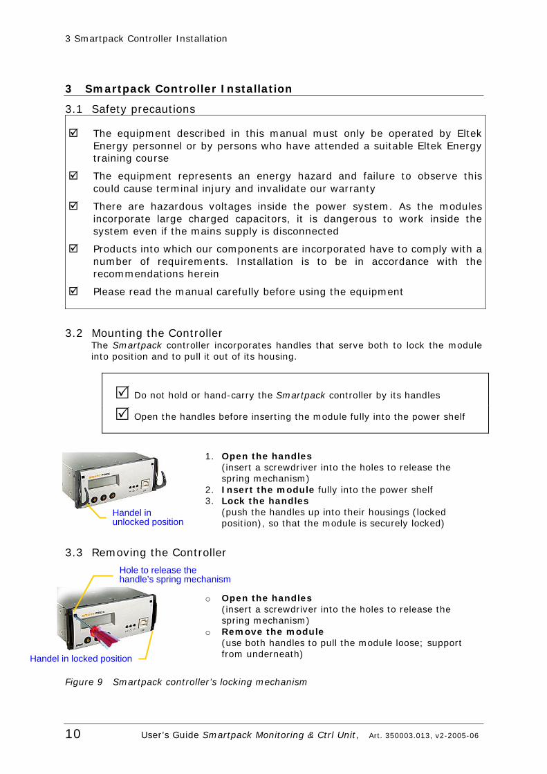
3.2 Mounting the Controller The Smartpack controller incorporates handles that serve both to lock the module into position and to pull it out of its housing.
Do not hold or hand-carry the Smartpack controller by its handles
Open the handles before inserting the module fully into the power shelf
1. Open the handles
(insert a screwdriver into the holes to release the spring mechanism)
2. Insert the module fully into the power shelf 3. Lock the handles
(push the handles up into their housings (locked position), so that the module is securely locked)
3.3 Removing the Controller
o Open the handles (insert a screwdriver into the holes to release the spring mechanism)
o Remove the module (use both handles to pull the module loose; support from underneath)
Figure 9 Smartpack controller’s locking mechanism
Handel in unlocked position
Handel in locked position
Hole to release the handle’s spring mechanism
4 Front Panel Operation
User’s Guide Smartpack Monitoring & Ctrl Unit, Art. 350003.013, v2-2005-06 11
4 Front Panel Operation This chapter describes the Smartpack controller’s keys and indicators, and how to operate the Flatpack2 DC power system from the controller’s front panel.
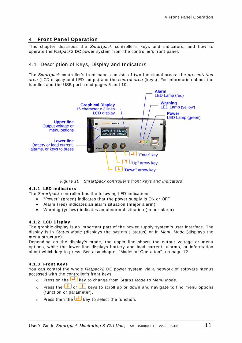
4.1 Description of Keys, Display and Indicators
The Smartpack controller’s front panel consists of two functional areas: the presentation area (LCD display and LED lamps) and the control area (keys). For information about the handles and the USB port, read pages 6 and 10.
Figure 10 Smartpack controller’s front keys and indicators
4.1.1 LED indicators The Smartpack controller has the following LED indications:
• “Power” (green) indicates that the power supply is ON or OFF • Alarm (red) indicates an alarm situation (major alarm) • Warning (yellow) indicates an abnormal situation (minor alarm)
4.1.2 LCD Display The graphic display is an important part of the power supply system’s user interface. The display is in Status Mode (displays the system’s status) or in Menu Mode (displays the menu structure). Depending on the display’s mode, the upper line shows the output voltage or menu options, while the lower line displays battery and load current, alarms, or information about which key to press. See also chapter “Modes of Operation”, on page 12.
4.1.3 Front Keys You can control the whole Flatpack2 DC power system via a network of software menus accessed with the controller’s front keys.
o Press on the key to change from Status Mode to Menu Mode.
o Press the or keys to scroll up or down and navigate to find menu options (function or parameter).
o Press then the key to select the function.
Power LED Lamp (green)
Warning LED Lamp (yellow)
AlarmLED Lamp (red)
Graphical Display 16 character x 2 lines
LCD display
”Up” arrow key
”Down” arrow key
”Enter” key
Upper lineOutput voltage or
menu options
Lower lineBattery or load current,
alarms, or keys to press

4 Front Panel Operation
12 User’s Guide Smartpack Monitoring & Ctrl Unit, Art. 350003.013, v2-2005-06
4.2 Modes of Operation The controller’s display is either in Status Mode or in Menu Mode.
4.2.1 Status Mode When the front keys are not in operation, the display is in Status Mode. The following information is then scrolled through the display: • The upper line continuously displays the battery voltage. • The lower line continuously scrolls the following information:
o Battery Current o Load Current o Active alarms o Other messages
4.2.2 Menu Mode When the front keys are in operation, the controller’s display switches to Menu Mode and the following information is scrolled through the display: • The upper line shows the name of the active menu or sub-menu. • The lower line indicates which key to press. Notice that if any of the keys are not pressed within 30 seconds, the display will switch from Menu Mode to back to the Status Mode.
4.3 Operating Menus, Overview The Flatpack2 DC power system’s functionality is accessed via a network of software menus and submenus, enabling you to configure and control the whole power system.
The functionality is divided in two different hierarchical menu structures: the User Options menus and the Service Options menus (password protected, only authorised personnel have access to them). Special not so frequently used options — such as calibration and adjustments — are included in the Service Options sub-menus.
Display in Status Mode
UserOption ServiceOption
4 Front Panel Operation
User’s Guide Smartpack Monitoring & Ctrl Unit, Art. 350003.013, v2-2005-06 13
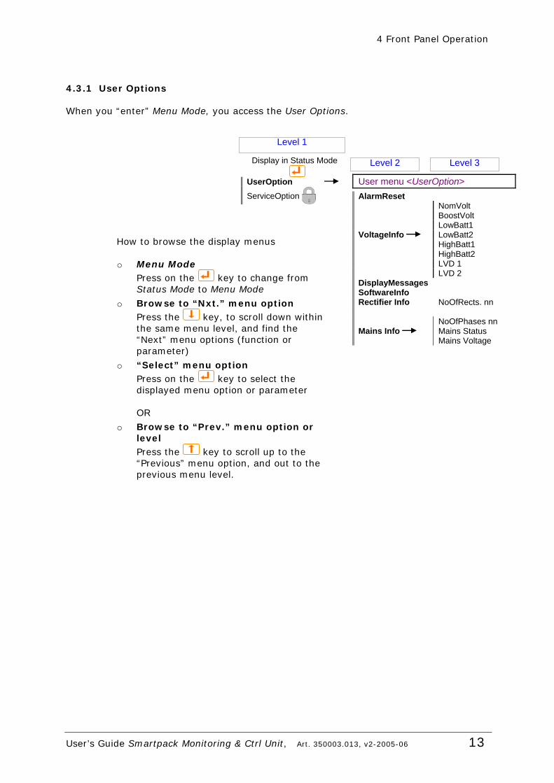
4.3.1 User Options
When you “enter” Menu Mode, you access the User Options.
How to browse the display menus o Menu Mode
Press on the key to change from Status Mode to Menu Mode
o Browse to “Nxt.” menu option Press the key, to scroll down within the same menu level, and find the “Next” menu options (function or parameter)
o “Select” menu option Press on the key to select the displayed menu option or parameter OR
o Browse to “Prev.” menu option or level Press the key to scroll up to the “Previous” menu option, and out to the previous menu level.
User menu <UserOption> AlarmReset NomVolt BoostVolt LowBatt1 VoltageInfo LowBatt2 HighBatt1 HighBatt2 LVD 1 LVD 2 DisplayMessages SoftwareInfo Rectifier Info NoOfRects. nn NoOfPhases nn Mains Info Mains Status Mains Voltage
Display in Status Mode
UserOption ServiceOption
Level 1
Level 2 Level 3
4 Front Panel Operation
14 User’s Guide Smartpack Monitoring & Ctrl Unit, Art. 350003.013, v2-2005-06
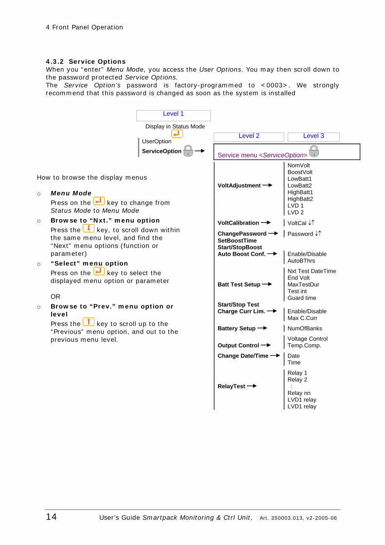
4.3.2 Service Options When you “enter” Menu Mode, you access the User Options. You may then scroll down to the password protected Service Options. The Service Option’s password is factory-programmed to <0003>. We strongly recommend that this password is changed as soon as the system is installed
How to browse the display menus o Menu Mode
Press on the key to change from Status Mode to Menu Mode
o Browse to “Nxt.” menu option Press the key, to scroll down within the same menu level, and find the “Next” menu options (function or parameter)
o “Select” menu option Press on the key to select the displayed menu option or parameter OR
o Browse to “Prev.” menu option or level Press the key to scroll up to the “Previous” menu option, and out to the previous menu level.
Display in Status Mode
UserOption
ServiceOption
Level 1
Level 2 Level 3
Service menu <ServiceOption> NomVolt BoostVolt LowBatt1 VoltAdjustment LowBatt2 HighBatt1 HighBatt2 LVD 1 LVD 2
VoltCalibration VoltCal ↓↑
ChangePassword Password ↓↑ SetBoostTime Start/StopBoost Auto Boost Conf. Enable/Disable AutoBThrs
Nxt Test DateTime End Volt Batt Test Setup MaxTestDur Test int Guard time Start/Stop Test Charge Curr Lim. Enable/Disable Max C.Curr
Battery Setup NumOfBanks
Voltage Control Output Control Temp.Comp.
Change Date/Time Date Time
Relay 1 Relay 2 RelayTest : Relay nn LVD1 relay LVD1 relay
5 Specifications
User’s Guide Smartpack Monitoring & Ctrl Unit, Art. 350003.013, v2-2005-06 15
5 Specifications
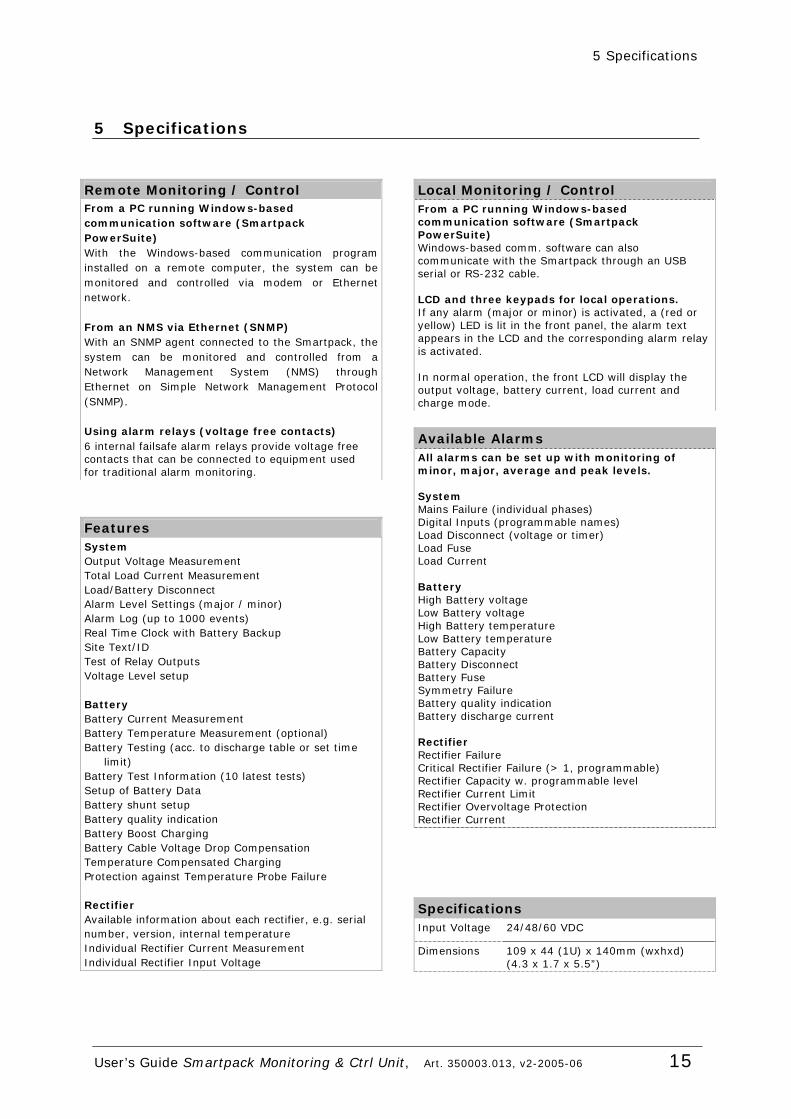
Remote Monitoring / Control From a PC running Windows-based communication software (Smartpack PowerSuite) With the Windows-based communication program installed on a remote computer, the system can be monitored and controlled via modem or Ethernet network. From an NMS via Ethernet (SNMP) With an SNMP agent connected to the Smartpack, the system can be monitored and controlled from a Network Management System (NMS) through Ethernet on Simple Network Management Protocol (SNMP). Using alarm relays (voltage free contacts) 6 internal failsafe alarm relays provide voltage free contacts that can be connected to equipment used for traditional alarm monitoring.
Features System Output Voltage Measurement Total Load Current Measurement Load/Battery Disconnect Alarm Level Settings (major / minor) Alarm Log (up to 1000 events) Real Time Clock with Battery Backup Site Text/ID Test of Relay Outputs Voltage Level setup Battery Battery Current Measurement Battery Temperature Measurement (optional) Battery Testing (acc. to discharge table or set time
limit) Battery Test Information (10 latest tests) Setup of Battery Data Battery shunt setup Battery quality indication Battery Boost Charging Battery Cable Voltage Drop Compensation Temperature Compensated Charging Protection against Temperature Probe Failure Rectifier Available information about each rectifier, e.g. serial number, version, internal temperature Individual Rectifier Current Measurement Individual Rectifier Input Voltage
Local Monitoring / Control From a PC running Windows-based communication software (Smartpack PowerSuite) Windows-based comm. software can also communicate with the Smartpack through an USB serial or RS-232 cable. LCD and three keypads for local operations. If any alarm (major or minor) is activated, a (red or yellow) LED is lit in the front panel, the alarm text appears in the LCD and the corresponding alarm relay is activated. In normal operation, the front LCD will display the output voltage, battery current, load current and charge mode.
Specifications Input Voltage 24/48/60 VDC
Dimensions 109 x 44 (1U) x 140mm (wxhxd) (4.3 x 1.7 x 5.5”)
Available Alarms All alarms can be set up with monitoring of minor, major, average and peak levels. System Mains Failure (individual phases) Digital Inputs (programmable names) Load Disconnect (voltage or timer) Load Fuse Load Current Battery High Battery voltage Low Battery voltage High Battery temperature Low Battery temperature Battery Capacity Battery Disconnect Battery Fuse Symmetry Failure Battery quality indication Battery discharge current Rectifier Rectifier Failure Critical Rectifier Failure (> 1, programmable) Rectifier Capacity w. programmable level Rectifier Current Limit Rectifier Overvoltage Protection Rectifier Current
6 Appendix
16 User’s Guide Smartpack Monitoring & Ctrl Unit, Art. 350003.013, v2-2005-06
6 Appendix
6.1 Functionality Description ⎯ Flatpack2 DC Power Systems In this chapter you can find helpful and more detailed descriptions of expressions, technical terms, functions, etc. used in Flatpack2 DC power supply systems.
6.1.1 Alarm Reset You can reset all active alarms with the Smartpack controller’s front keys (e.g. “UserOption>AlarmReset”). The controller will immediately report alarm conditions that are still active. The Flatpack2 DC power system can be configured with automatic or manual alarm reset. When Automatic Alarm Reset is enabled (default) ⎯ and the alarm condition no longer exists ⎯ the Smartpack controller will switch the alarm indicators and relays to indicate that normal operation is established. When Manual Alarm Reset is enabled ⎯ and the alarm condition no longer exists ⎯ the operator must reset the alarm manually.
6.1.2 Display System Voltages You can display important system voltages with the Smartpack controller’s front keys (e.g. “UserOption>VoltageInfo”), as listed below:
o NomVolt Nominal output voltage
o BoostVolt Battery boost-charging voltage
o LowBatt1 Voltage limit for Low Battery Alarm 1
o LowBatt2 Voltage limit for Low Battery Alarm 2
o HighBatt1 Voltage limit for High Battery Alarm 1
o HighBatt2 Voltage limit for High Battery Alarm 2
o LVD 1 Voltage limit for Low Voltage Disconnect unit 1
o LVD 2 Voltage limit for Low Voltage Disconnect unit 2
6.1.3 Display Alarm Messages (Alarm Log) You can browse through the stored alarm messages using the Smartpack controller’s front keys (e.g. “UserOption>DisplayMessages”). The Smartpack controller’s alarm log may store up to 1000 chronological events. Each log entry contains event text, event action, time and date. When the log is full, the oldest value is overwritten. The log is stored in EEPROM.
6 Appendix
User’s Guide Smartpack Monitoring & Ctrl Unit, Art. 350003.013, v2-2005-06 17
6.1.4 Plug-and-Play Flatpack2 Rectifiers (Rectifier Info) You can display the number of communicating Flatpack2 rectifiers in the system by using the Smartpack controller’s front keys (e.g. “UserOption>Rectifier Info”). The following rectifier information is available in the Smartpack controller:
o Number of rectifiers installed in the system. o Rectifier ID and serial number o Rectifier current o Rectifier input voltage o Rectifier temperature o Rectifier status
The green LED on the rectifier front panel will flash while the controller is accessing information from a specified rectifier. The Smartpack controller sends out status messages every 200ms to all the Flatpack2 rectifiers connected to the CAN bus, such as:
o The Smartpack controller’s status o Current Limit Reference o Measured Output Voltage o Reference Output Voltage o Over-voltage Protection Reference o Etc.
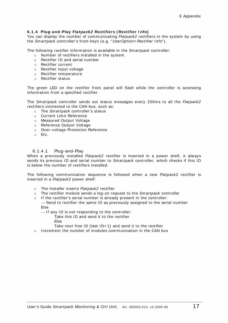
6.1.4.1 Plug-and-Play When a previously installed Flatpack2 rectifier is inserted in a power shelf, it always sends its previous ID and serial number to Smartpack controller, which checks if this ID is below the number of rectifiers installed. The following communication sequence is followed when a new Flatpack2 rectifier is inserted in a Flatpack2 power shelf:
o The installer inserts Flatpack2 rectifier o The rectifier module sends a log-on request to the Smartpack controller o If the rectifier’s serial number is already present in the controller:
⎯ Send to rectifier the same ID as previously assigned to the serial number Else ⎯ If any ID is not responding to the controller: Take this ID and send it to the rectifier Else Take next free ID (last ID+1) and send it to the rectifier
o Increment the number of modules communication in the CAN bus
6 Appendix
18 User’s Guide Smartpack Monitoring & Ctrl Unit, Art. 350003.013, v2-2005-06
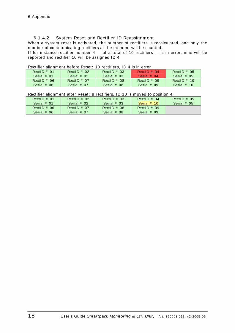
6.1.4.2 System Reset and Rectifier ID Reassignment When a system reset is activated, the number of rectifiers is recalculated, and only the number of communicating rectifiers at the moment will be counted. If for instance rectifier number 4 ⎯ of a total of 10 rectifiers ⎯ is in error, nine will be reported and rectifier 10 will be assigned ID 4. Rectifier alignment before Reset: 10 rectifiers, ID 4 is in error
RectID # 01 Serial # 01
RectID # 02 Serial # 02
RectID # 03 Serial # 03
RectID # 04 Serial # 04
RectID # 05 Serial # 05
RectID # 06 Serial # 06
RectID # 07 Serial # 07
RectID # 08 Serial # 08
RectID # 09 Serial # 09
RectID # 10 Serial # 10
Rectifier alignment after Reset: 9 rectifiers, ID 10 is moved to position 4
RectID # 01 Serial # 01
RectID # 02 Serial # 02
RectID # 03 Serial # 03
RectID # 04 Serial # 10
RectID # 05 Serial # 05
RectID # 06 Serial # 06
RectID # 07 Serial # 07
RectID # 08 Serial # 08
RectID # 09 Serial # 09
6 Appendix
User’s Guide Smartpack Monitoring & Ctrl Unit, Art. 350003.013, v2-2005-06 19
6.1.5 Mains Assignment versus Rectifier ID Normally, the rectifier ID number 1 is assigned to mains phase 1, the rectifier ID number 2 is assigned to mains phase 2 and rectifier ID number 3 is assigned to mains phase 3. If rectifiers with ID number 1, 2 and 3 fails, the rectifier with ID number 4, 5, and 6 will take their positions. An alarm monitor is used for the mains phases. In a three phase system, the alarm monitor can e.g. be configured to report a warning if one phase fails, and to report an alarm if two phases fail.
6.1.6 About Battery Banks, strings, etc
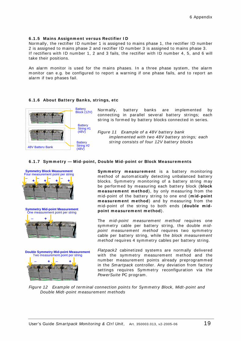
Normally, battery banks are implemented by connecting in parallel several battery strings; each string is formed by battery blocks connected in series.
Figure 11 Example of a 48V battery bank implemented with two 48V battery strings; each string consists of four 12V battery blocks
6.1.7 Symmetry — Mid-point, Double Mid-point or Block Measurements
Symmetry measurement is a battery monitoring method of automatically detecting unbalanced battery blocks. Symmetry monitoring of a battery string may be performed by measuring each battery block (block measurement method), by only measuring from the mid-point of the battery string to one end (mid-point measurement method) and by measuring from the mid-point of the string to both ends (double mid-point measurement method). The mid-point measurement method requires one symmetry cable per battery string, the double mid-point measurement method requires two symmetry cable per battery string, while the block measurement method requires 4 symmetry cables per battery string. Flatpack2 cabinetized systems are normally delivered with the symmetry measurement method and the number measurement points already preprogrammed in the Smartpack controller. Any deviation from factory settings requires Symmetry reconfiguration via the PowerSuite PC program.
Figure 12 Example of terminal connection points for Symmetry Block, Midt-point and Double Midt-point measurement methods
48V Battery Bank
Battery String #1 (48V)
Battery Block (12V)
Battery String #2 (48V)
Symmetry Block MeasurementFour measurement point per string
+ − + − + − + −
Symmetry Mid-point Measurement One measurement point per string
+ −
Double Symmetry Mid-point Measurement Two measurement point per string
+ − +−

www.eltekenergy.com
ELTEK Energy P-O- BOX 2340 StØmsØ N-3003 DRAMMEN NORWAY Phone: +47 32203200 Telefax: +47 32203210 Internet: http://www.eltekenergy.com e-mail: [email protected]
Location Company Telephone Fax Norway Eltek Energy AS +47 32 20 32 00 +47 32 20 32 10 Americas Eltek Energy, LLC +1 815 459 9100 +1 815 459 9118 Asia/Pacific Eltek Energy Pte Ltd. +65 6 7732326 +65 6 7753602 China Eltek Energy Ltd. +852 28982689 +852 28983189 Europe Eltek Energy UK Ltd. +44 1442 219355 +44 1442 245894 Middle East Eltek Middle East +971 4 887 1176 +971 4 887 1175