Flat Cables - 佳昭企業有限公司AXON’ offers flat cables with insulation tapes of different...
14
Flat Cables FFC-Flat Flexible Cables AXOJUMP ® 11 www.axon-cable.com - RELEASED APRIL 2009 © 2009/A - AXON’ CABLE - FLAT FLEXIBLE CABLES AND FLAT CABLE ASSEMBLIES SAME NUMBER OF CONDUCTORS BUT DECREASING PITCH 0.3 mm PITCH VERSUS 2.54 mm PITCH Standard Flat Flexible Cables Pitches The standard range of FFC-Flat Flexible Cables AXOJUMP ® consists of the following pitches: - 0.30 mm, - 0.50 mm, - 0.80 mm, - 1.00 mm, - 1.25 mm, - 1.27 mm, - 2.54 mm. Other pitches can be manufactured upon request.
Transcript of Flat Cables - 佳昭企業有限公司AXON’ offers flat cables with insulation tapes of different...

Flat Cables
FFC-Flat Flexible Cables AXOJUMP®
11
www.axon-cable.com - RELEASED APRIL 2009© 2009/A - AXON’ CABLE - FLAT FLEXIBLE CABLES AND FLAT CABLE ASSEMBLIES
SAME NUMBER OF CONDUCTORS BUT DECREASING PITCH
0.3 mm PITCH VERSUS 2.54 mm PITCH
Standard Flat Flexible Cables
Pitches
The standard range of FFC-Flat Flexible Cables AXOJUMP® consists of the following pitches:
- 0.30 mm,
- 0.50 mm,
- 0.80 mm,
- 1.00 mm,
- 1.25 mm,
- 1.27 mm,
- 2.54 mm.
Other pitches can be manufactured upon request.
12
RELEASED AUGUST 2009 - www.axon-cable.com© 2009/A - AXON’ CABLE - FLAT FLEXIBLE CABLES AND FLAT CABLE ASSEMBLIES
FLAT CABLES
FFC, TYPE B - STRIPPED VERSION
FFC, TYPE A
FFC, BUS BAR VERSION
Type A
Reinforcements F1 and F2 at both ends of the cable, on the same side.
Removable connection › (connector/connector)
- 2 Polyester reinforcements, standard or “easy-to-insert” version.
Solder connection › (solder/solder)
- 2 Polyimide reinforcements.
Mixed connection › (solder/connector)
- Soldering at one end: use of Polyimide reinforcement.- Removable at the other end (connector): use of a Polyester reinforcement,
standard or “easy-to-insert” version.
Type B
One single reinforcement F1 at one end / no reinforcement at the other end.
Mixed connection › (solder/connector)
- Soldering at one end: stripping or bus bar version.- Removable at the other end (connector): use of a Polyester reinforcement,
standard or “easy-to-insert” version.
Connection schemesSee identification code at the end of the brochure.
Each type of stripping has its own letter code: A, B, C or D.
For each end a strip length (S1, S2), a connection (see page 14) and a reinforcement length (F1, F2) is defined.

13axojump®
www.axon-cable.com - RELEASED AUGUST 2009© 2009/A - AXON’ CABLE - FLAT FLEXIBLE CABLES AND FLAT CABLE ASSEMBLIES
FFC, BUS BAR VERSION
FFC, TYPE C – STRIPPED VERSION
FFC, TYPE D
Type C
No reinforcement.
Solder connection (solder/solder) › - Stripping (without reinforcement) at both ends.
Note: the stripped conductors are unprotected and therefore fragile. They may be damaged during shipment and storage. AXON’ recommends the use of bus bar version to protect the conductors.
Type D
2 reinforcements F1 and F2 at the both ends on opposite sides.
Removable connection › (connector/connector)
- 2 Polyester reinforcements, standard or “easy-to-insert” version.
Solder connection › (solder/solder)
- 2 Polyimide reinforcements.
Mixed connection › (solder/connector)
- Soldering at one end: use of a Polyimide reinforcement.- Removable at the other end (connector): use of a Polyester reinforcement,
standard or “easy-to-insert” version.

14
RELEASED AUGUST 2009 - www.axon-cable.com© 2009/A - AXON’ CABLE - FLAT FLEXIBLE CABLES AND FLAT CABLE ASSEMBLIES
FLAT CABLES
FFC, VERSION R REINFORCEMENT
FFC, VERSION B REINFORCEMENT
FFC, VERSION T REINFORCEMENT
Connection with ZIF or LIF connectors
Polyester reinforcement version B, R, W, J, K
for termination to connectors.
› Version B: blue Polyester tape.
› Version R: red Polyester tape.
› Version W: white Polyester tape, mainly for 0.30 mm pitch FFC’s. The insulation tape remains between conductor and reinforcement tape.
Version J or K: › blue Polyester tape, mainly used for gold plated FFC.
See summary of reinforcement tapes page 16.
Connection with soldering
«Bus bar» reinforcement version T
Bus bar version: › the pitch between the conductors is maintained thanks to a blue tape at the end.
Connection definitionSee identification code at the end of the brochure.
15axojump®
www.axon-cable.com - RELEASED AUGUST 2009© 2009/A - AXON’ CABLE - FLAT FLEXIBLE CABLES AND FLAT CABLE ASSEMBLIES
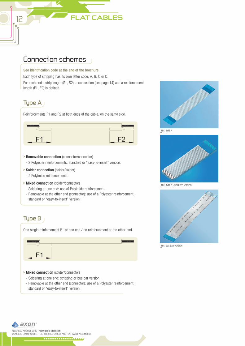
FFC, VERSION E REINFORCEMENT
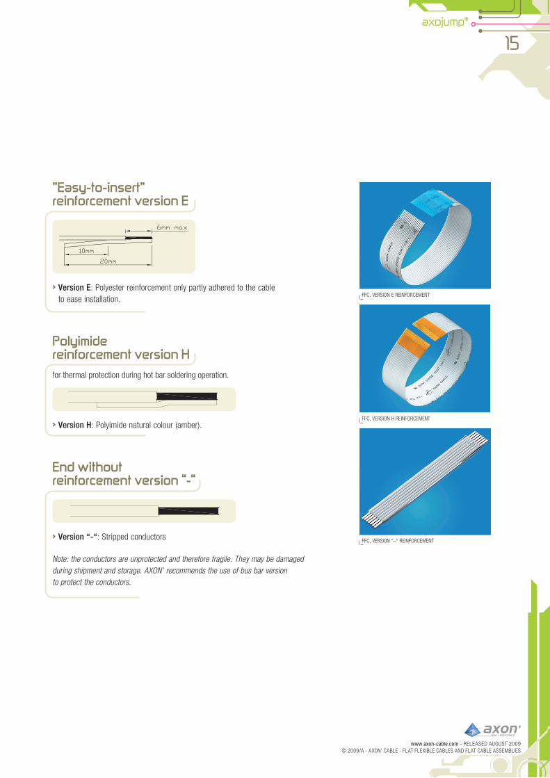
FFC, VERSION H REINFORCEMENT
FFC, VERSION “–“ REINFORCEMENT
”Easy-to-insert” reinforcement version E
Version E › : Polyester reinforcement only partly adhered to the cable to ease installation.
Polyimide reinforcement version Hfor thermal protection during hot bar soldering operation.
› Version H: Polyimide natural colour (amber).
End without reinforcement version “-“
Version “-“ › : Stripped conductors
Note: the conductors are unprotected and therefore fragile. They may be damaged during shipment and storage. AXON’ recommends the use of bus bar version to protect the conductors.
16
RELEASED AUGUST 2009 - www.axon-cable.com© 2009/A - AXON’ CABLE - FLAT FLEXIBLE CABLES AND FLAT CABLE ASSEMBLIES
FLAT CABLES
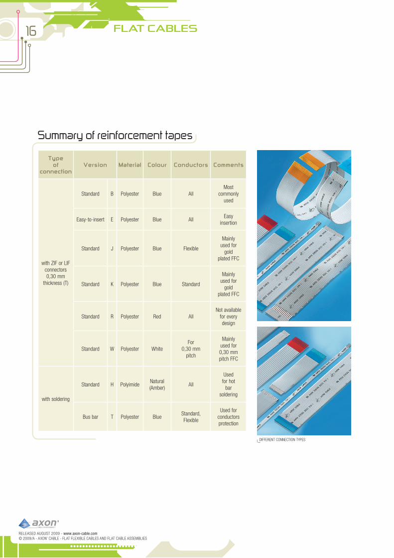
Summary of reinforcement tapes
DIFFERENT CONNECTION TYPES
Type of
connectionVersion Material Colour Conductors Comments
with ZIF or LIF connectors 0,30 mm
thickness (T)
Standard B Polyester Blue AllMost
commonly used
Easy-to-insert E Polyester Blue AllEasy
insertion
Standard J Polyester Blue Flexible
Mainly used for
gold plated FFC
Standard K Polyester Blue Standard
Mainly used for
gold plated FFC
Standard R Polyester Red AllNot available
for every design
Standard W Polyester WhiteFor
0,30 mm pitch
Mainly used for 0,30 mm pitch FFC
with soldering
Standard H PolyimideNatural (Amber)
All
Used for hot
bar soldering
Bus bar T Polyester BlueStandard, Flexible
Used for conductors protection

17axojump®
www.axon-cable.com - RELEASED AUGUST 2009© 2009/A - AXON’ CABLE - FLAT FLEXIBLE CABLES AND FLAT CABLE ASSEMBLIES
Insulation tapes
See identification code at the end of the brochure.
AXON’ offers flat cables with insulation tapes of different thicknesses according to the required flexibility, temperature resistance, colour and marking.
Type of tape Compatible pitches (mm) Material UL style
Maximum temperature
rating
Maximum voltage rating
Colour Conductors Comments
S Standard 0.30 to 2.54 Polyester 20706 105°C 60 Volts White Standard, Flexible
Tin or gold plated
conductors
E* Extra-flexible 0.50 to 1.27 Polyester 20706 105°C 60 Volts White Extra-flexible, ultra-flexible
Tin or gold plated
conductors
H 0.50 to 2.54 Polyester 2643 105°C 300 Volts White Standard, Flexible
Tin or gold plated
conductors
K 0.50 to 2.54 Polyester 2896 80°C 30 Volts White Flexible Tin
plated conductors
L** 0.50 to 2.54 Polyester 2896 80°C 30 Volts White Standard, flexible
Tin plated
conductors
X
Used for special designs, please
contact us
Polyimide 21039 125°C 60 Volts Amber Special conductors
Tin or gold plated
conductors
* Black insulation on request** UL marking on request
AXOJUMP® Flat Flexible Cables can be used at below freezing temperatures as low as -40°C.

18
RELEASED AUGUST 2009 - www.axon-cable.com© 2009/A - AXON’ CABLE - FLAT FLEXIBLE CABLES AND FLAT CABLE ASSEMBLIES
FLAT CABLES
Standard version S
Pitch (mm)
Width (mm)
Thickness (mm)
Resistance at 20° C Ω/ Km
0.50 0.30
0.10
730 max
0.80 0.50 400 max
1.00 0.70 280 max
1.25/1.27 0.80 250 max
2.54 1.57 0.076 194 nom
Marking
See identification code at the end of the brochure.
Version A: › both sides unmarked.
› Version B: one side marked with standard UL printing (if originally marked tape is available) and the other side unmarked. Specific markings can be studied upon request.
UL MARKING
POLYIMIDE INSULATION : UPPER TAPE OPAqUE/LOWER TAPE CLEAR ; INK-JET MARKING
INK-JET MARKING
ORIGINALLY MARKED TAPE UL STYLE AND AXON’ LOGO
ConductorsSee identification code at the end of the brochure.

19axojump®
www.axon-cable.com - RELEASED AUGUST 2009© 2009/A - AXON’ CABLE - FLAT FLEXIBLE CABLES AND FLAT CABLE ASSEMBLIES
FLAT TIN PLATED COPPER CONDUCTOR
CONDUCTOR MANUFACTURING
GOLD PLATING AT EXPOSED ENDS
Flexible version F
Pitch (mm)
Width (mm)
Thickness (mm)
Resistance at 20° C Ω/ Km
0.30 0.15
0.05
3164 max
0.50 0.30 1460 max
0.80 0.50 800 max
1.00 0.70 520 max
1.25/1.27 0.80 500 max
Extra flexible version E (E tape only)
Pitch (mm)
Width (mm)
Thickness (mm)
Resistance at 20° C Ω/ Km
0.50 0.30
0.035
1730 max
0.80 0.50 1030 max
1.00 0.70 720 max
1.25/1.27 0.80 643 max
Ultra flexible version U (E tape only)
Pitch (mm)
Width (mm)
Thickness (mm)
Resistance at 20° C Ω/ Km
1.00 0.600.025
1500 max
1.25/1.27 0.80 970 max
20
RELEASED AUGUST 2009 - www.axon-cable.com© 2009/A - AXON’ CABLE - FLAT FLEXIBLE CABLES AND FLAT CABLE ASSEMBLIES
FLAT CABLES
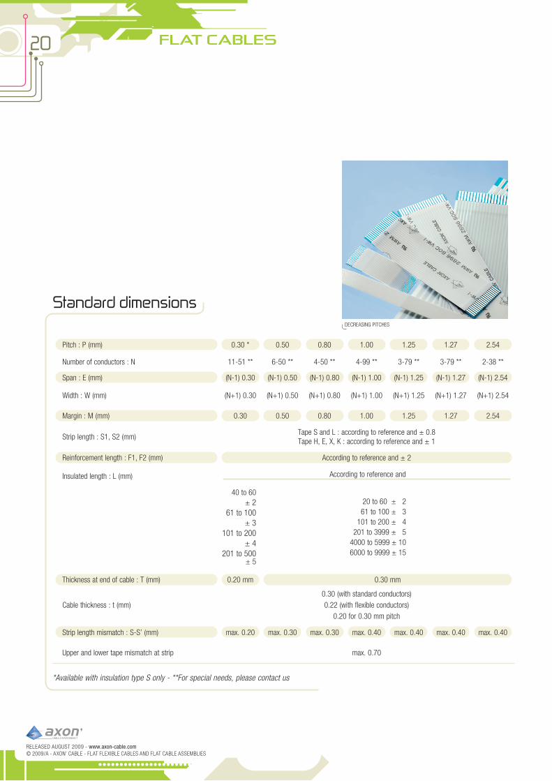
Standard dimensions
Pitch : P (mm) 0.30 * 0.50 0.80 1.00 1.25 1.27 2.54
Number of conductors : N 11-51 ** 6-50 ** 4-50 ** 4-99 ** 3-79 ** 3-79 ** 2-38 **
Span : E (mm) (N-1) 0.30 (N-1) 0.50 (N-1) 0.80 (N-1) 1.00 (N-1) 1.25 (N-1) 1.27 (N-1) 2.54
Width : W (mm) (N+1) 0.30 (N+1) 0.50 (N+1) 0.80 (N+1) 1.00 (N+1) 1.25 (N+1) 1.27 (N+1) 2.54
Margin : M (mm) 0.30 0.50 0.80 1.00 1.25 1.27 2.54
Strip length : S1, S2 (mm)Tape S and L : according to reference and ± 0.8Tape H, E, X, K : according to reference and ± 1
Reinforcement length : F1, F2 (mm) According to reference and ± 2
Insulated length : L (mm) According to reference and
40 to 60 ± 2
61 to 100 ± 3
101 to 200 ± 4
201 to 500 ± 5
20 to 60 ± 261 to 100 ± 3
101 to 200 ± 4201 to 3999 ± 5
4000 to 5999 ± 106000 to 9999 ± 15
Thickness at end of cable : T (mm) 0.20 mm 0.30 mm
Cable thickness : t (mm)0.30 (with standard conductors)0.22 (with flexible conductors)
0.20 for 0.30 mm pitch
Strip length mismatch : S-S’ (mm) max. 0.20 max. 0.30 max. 0.30 max. 0.40 max. 0.40 max. 0.40 max. 0.40
Upper and lower tape mismatch at strip max. 0.70
*Available with insulation type S only - **For special needs, please contact us
DECREASING PITCHES
21axojump®
www.axon-cable.com - RELEASED AUGUST 2009© 2009/A - AXON’ CABLE - FLAT FLEXIBLE CABLES AND FLAT CABLE ASSEMBLIES
ALUMINIUM ShIELDING
pAINTED ShIELD
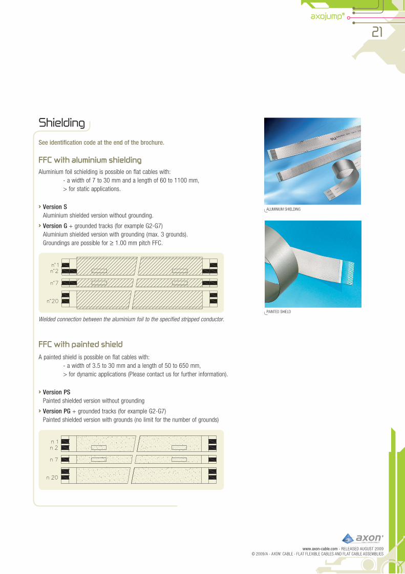
Shielding
See identification code at the end of the brochure.
FFC with aluminium shieldingAluminium foil schielding is possible on flat cables with: - a width of 7 to 30 mm and a length of 60 to 1100 mm, > for static applications.
› Version SAluminium shielded version without grounding.
› Version G + grounded tracks (for example G2-G7)Aluminium shielded version with grounding (max. 3 grounds).Groundings are possible for ≥ 1.00 mm pitch FFC.
Welded connection between the aluminium foil to the specified stripped conductor.
FFC with painted shield
A painted shield is possible on flat cables with: - a width of 3.5 to 30 mm and a length of 50 to 650 mm, > for dynamic applications (please contact us for further information).
› Version PSpainted shielded version without grounding
Version PG › + grounded tracks (for example G2-G7)painted shielded version with grounds (no limit for the number of grounds)

22
RELEASED AUGUST 2009 - www.axon-cable.com© 2009/A - AXON’ CABLE - FLAT FLEXIBLE CABLES AND FLAT CABLE ASSEMBLIES
FLAT CABLES
pUNChINGS FOLDED AND SOLDERED
INk jET MARkING / Fh 28 pUNChING
Special products
Responding to a growing demand for custom designed products, AXON’ has developed numerous special versions of flat cable:
folded versions, ›
non-standard or hybrid pitches, ›
special insulation tapes, ›
double sided adhesive pads, ›
crimped contacts, ›
punching, marking, slitting, stripping and ›special mounting/fastening.
AXON’ can quickly develop the necessary tooling required to manufacture customised cables. Our team of technical experts will offer you design assistance and the best cable solution suited to your needs.
Folding
- adapted to the equipment’s shape.- easy to install.
Punching
- facilitates positioning of the cable in the equipment.
- polarisation (pOkA YOkE).- cable retained in the connector.- improves the contact between
conductors and connector.

23axojump®
www.axon-cable.com - RELEASED AUGUST 2009© 2009/A - AXON’ CABLE - FLAT FLEXIBLE CABLES AND FLAT CABLE ASSEMBLIES
LINE MARkING ON ThE REINFORCEMENT SLITTINGS
ADDITIONAL REINFORCEMENT
SpECIFIC pOSITIONNING DEVICE
Slitting
- connection to multiple pCB’s at different heights or to different parts of the same pCB.
- facilitates positioning of the cable into the equipment.
- polarisation (pOkA YOkE).
Specific marking
- identification of the product.
- polarisation.
- marking of texts, lines, symbols.
Other custom options
Additional insulation layers:
- Increases abrasion resistance.
- Improves electrical insulation.
- Facilitates hot bar soldering.
Mounting brackets.
Strain relieving solder joints.
- Enhances cable/connector retention.
AXON’ is at your disposal for any special design.
We can adapt our products to your manufacturing process.
MOUNTING BRACkETS

Indentification code for AXOJUMP® Flat Flexible Cables
www.axon-cable.com - RELEASED AUGUST 2009© 2009 - AXON’ CABLE - FLAT FLEXIBLE CABLES AND FLAT CABLE ASSEMBLIES
General drawing
Reinforcement length F2
Insulated length L
Strip length S1 Strip length S2
Pitch P
Span E
Width w
Margin M
Reinforcement length F1
FFC 1.00 A 20/ 0075 S 5.0-5.0- 10.0-10.0 F A BB/ G 2-7
Option S: Aluminium shielding without grounding G: Grounded Aluminium shielding + n° of grounded conductors PS: Painted shielding without groundingPG: Painted shielding with grounding + n° of grounded conductorsAU: Gold plated contactsM: Ink-jet markingN: Notches, punchingsL: Adhesive labels on the cableF1: Foldings + n° of foldsR1: Marking of a line on the reinforcements + n° of markingsV1: Additional reinforcement tape + n° of additional reinforcements
UL marking of the insulation tapeA: tape without UL marking B: tape with UL marking
Type of conductor S: static F: flexible (50 µm)
E: extra-flexible (35 µm)U: ultra-flexible (25 µm)
Reinforcement length F1 and F2 in mm
Strip length S1 and S2 in mm
Type of insulation tape: S / E / L / H / K / X
Insulated length in mm
Number of conductors
Pitch in mm: 0.30 / 0.50 / 0.80 / 1.00 / 1.25 / 1.27 / 2.54
Flat Flexible Cable
Type of connection A: one reinforcement at each end on the same side of the FFCB: one single reinforcementC: no reinforcementD: one reinforcement at each end on opposite sides of the FFC
B, J, K: Blue PolyesterR: Red PolyesterW: White Polyester H: Polyimide
E: Polyester « Easy-to-insert » type “-”: No reinforcementT : « Bus bar » type
Definition of the connection F1 and F2