FlashStack Infrastructure as a Code (IaC) for Red Hat ...
109
FlashStack Infrastructure as a Code (IaC) for Red Hat OpenShift Container Platform 4.7 Bare Metal Bare Metal Installer Provisioned Infrastructure for Red Hat OpenShift Container Platform 4.7 with Cisco UCS, Cisco Nexus, Pure FlashArray//X R3 Family Storage, and Red Hat Ansible Published: May 2021 In partnership with:
Transcript of FlashStack Infrastructure as a Code (IaC) for Red Hat ...
FlashStack Infrastructure as a Code (IaC) for
Red Hat OpenShift Container Platform 4.7
Bare Metal Bare Metal Installer Provisioned Infrastructure for Red Hat
OpenShift Container Platform 4.7 with Cisco UCS, Cisco Nexus,
Pure FlashArray//X R3 Family Storage, and Red Hat Ansible
Published: May 2021
In partnership with:
About the Cisco Validated Design Program
The Cisco Validated Design (CVD) program consists of systems and solutions designed, tested, and document-
ed to facilitate faster, more reliable, and more predictable customer deployments. For more information, go to:
http://www.cisco.com/go/designzone.
ALL DESIGNS, SPECIFICATIONS, STATEMENTS, INFORMATION, AND RECOMMENDATIONS (COLLECTIVELY,
"DESIGNS") IN THIS MANUAL ARE PRESENTED "AS IS," WITH ALL FAULTS. CISCO AND ITS SUPPLIERS DIS-
CLAIM ALL WARRANTIES, INCLUDING, WITHOUT LIMITATION, THE WARRANTY OF MERCHANTABILITY, FIT-
NESS FOR A PARTICULAR PURPOSE AND NONINFRINGEMENT OR ARISING FROM A COURSE OF DEALING,
USAGE, OR TRADE PRACTICE. IN NO EVENT SHALL CISCO OR ITS SUPPLIERS BE LIABLE FOR ANY INDIRECT,
SPECIAL, CONSEQUENTIAL, OR INCIDENTAL DAMAGES, INCLUDING, WITHOUT LIMITATION, LOST PROFITS
OR LOSS OR DAMAGE TO DATA ARISING OUT OF THE USE OR INABILITY TO USE THE DESIGNS, EVEN IF CIS-
CO OR ITS SUPPLIERS HAVE BEEN ADVISED OF THE POSSIBILITY OF SUCH DAMAGES.
THE DESIGNS ARE SUBJECT TO CHANGE WITHOUT NOTICE. USERS ARE SOLELY RESPONSIBLE FOR THEIR
APPLICATION OF THE DESIGNS. THE DESIGNS DO NOT CONSTITUTE THE TECHNICAL OR OTHER PROFES-
SIONAL ADVICE OF CISCO, ITS SUPPLIERS OR PARTNERS. USERS SHOULD CONSULT THEIR OWN TECH-
NICAL ADVISORS BEFORE IMPLEMENTING THE DESIGNS. RESULTS MAY VARY DEPENDING ON FACTORS NOT
TESTED BY CISCO.
CCDE, CCENT, Cisco Eos, Cisco Lumin, Cisco Nexus, Cisco StadiumVision, Cisco TelePresence, Cisco WebEx,
the Cisco logo, DCE, and Welcome to the Human Network are trademarks; Changing the Way We Work, Live,
Play, and Learn and Cisco Store are service marks; and Access Registrar, Aironet, AsyncOS, Bringing the Meet-
ing To You, Catalyst, CCDA, CCDP, CCIE, CCIP, CCNA, CCNP, CCSP, CCVP, Cisco, the Cisco Certified Inter-
network Expert logo, Cisco IOS, Cisco Press, Cisco Systems, Cisco Systems Capital, the Cisco Systems logo,
Cisco Unified Computing System (Cisco UCS), Cisco UCS B-Series Blade Servers, Cisco UCS C-Series Rack
Servers, Cisco UCS S-Series Storage Servers, Cisco UCS Manager, Cisco UCS Management Software, Cisco
Unified Fabric, Cisco Application Centric Infrastructure, Cisco Nexus 9000 Series, Cisco Nexus 7000 Series.
Cisco Prime Data Center Network Manager, Cisco NX-OS Software, Cisco MDS Series, Cisco Unity, Collabora-
tion Without Limitation, EtherFast, EtherSwitch, Event Center, Fast Step, Follow Me Browsing, FormShare, Giga-
Drive, HomeLink, Internet Quotient, IOS, iPhone, iQuick Study, LightStream, Linksys, MediaTone, MeetingPlace,
MeetingPlace Chime Sound, MGX, Networkers, Networking Academy, Network Registrar, PCNow, PIX, Power-
Panels, ProConnect, ScriptShare, SenderBase, SMARTnet, Spectrum Expert, StackWise, The Fastest Way to In-
crease Your Internet Quotient, TransPath, WebEx, and the WebEx logo are registered trademarks of Cisco Sys-
tems, Inc. and/or its affiliates in the United States and certain other countries. (LDW_3).
All other trademarks mentioned in this document or website are the property of their respective owners. The use
of the word partner does not imply a partnership relationship between Cisco and any other company. (0809R)
© 2021 Cisco Systems, Inc. All rights reserved.
Executive Summary
To help organizations with their digital transformation and to enhance their cloud-native and application modern-
ization practices, Cisco and Pure have partnered to produce this Cisco Validated Design (CVD) for the
FlashStack™ for Red Hat OpenShift Container Platform bare metal solution delivered as Infrastructure as Code
(IaC).
FlashStack delivers an integrated architecture that incorporates compute, storage, and network design best
practices thereby minimizing IT risks by validating the integrated architecture to ensure compatibility between
various components. The solution also addresses IT pain points by providing documented design guidance, de-
ployment guidance and support that can be used in various stages (planning, designing and implementation) of a
deployment. FlashStack delivered as IaC further eliminates error-prone manual tasks, allowing quicker and more
consistent solution deployments.
Red Hat® OpenShift® is an enterprise-ready Kubernetes container platform with full-stack automated operations
to manage hybrid cloud and multi-cloud deployments. Red Hat OpenShift is optimized to improve developer
productivity and promote innovation. The Red Hat OpenShift Container Platform gives developers a self-service
platform on which to build and run containerized applications. With Red Hat OpenShift you can quickly start cre-
ating new cloud-native applications or cloud-enabling existing applications and spawning an environment for a
new microservice in minutes.
Combining Red Hat OpenShift with FlashStack solution can simplify the deployment and the management of the
container infrastructure. The Red Hat Ansible integration with FlashStack solution automates deployment of
FlashStack infrastructure along with the OpenShift Container platform installation enabling customers to take ad-
vantage of programming and automating the infrastructure at scale with agility, extending the benefits of auto-
mation to the entire stack.
This combined solution helps organizations achieve the speed, flexibility, security, and scale required for all their
application modernization and digital transformation initiatives.
Solution Overview
Introduction
The featured FlashStack for OpenShift Container platform solution delivered as IaC is a pre-designed, integrat-
ed, and validated architecture for the data center that combines Cisco UCS servers, the Cisco Nexus family of
switches, and Pure FlashArray//X R3 family storage into a single, flexible architecture. FlashStack is designed for
high availability (HA), with no single point of failure, while maintaining cost-effectiveness and flexibility in the de-
sign to support a wide variety of workloads. The FlashStack solution covered in this document is for Bare Metal
implementation of Red Hat OpenShift Container Platform (OCP) installer provisioned infrastructure (IPI), built on
Enterprise Kubernetes for an on-premises deployment.
Integration between OpenShift Container Platform and the storage and data management services occur at sev-
eral levels, all of which are captured in the design aspects of this document. The main storage integration is
based on Container Storage Interface (CSI) Driver for Pure block storage systems, which enables container or-
chestrators such as Kubernetes to manage the life cycle of persistent storage.
The OCP platform is installed as a Bare Metal cluster with the OCP nodes running Red Hat Enterprise Linux Co-
reOS (RHCOS) on Cisco UCS servers.
The following design and deployment aspects of the FlashStack for OCP solution are explained in this document:
● Red Hat OpenShift Container Platform 4.7
● Red Hat OpenShift Virtualization 2.6
● FlashStack converged infrastructure
● Pure Service Orchestrator – Dynamic storage provisioner for OpenShift
● Pure Service Orchestrator Explorer – Web based user interface for PSO
● Cisco UCS Manager 4.1.(3)
The document also covers key configurations based on the validated environment and best practices.
Audience
The intended audience of this document includes but is not limited to data scientists, IT architects, sales engi-
neers, field consultants, professional services, IT managers, partner engineering, DevOps, and Site Reliability
Engineers (SREs) and customers who want to take advantage of an infrastructure built to deliver IT efficiency and
enable IT innovation.
Purpose of This Document
The purpose of this design and deployment guide is to provide a reference architecture with specific examples
indicating how the solution was designed, deployed, and tested. In addition, the document provides several best
practices and recommendations that simplify your implementation of this solution.
What’s New in this Release?
The following elements distinguish this version of FlashStack from previously published solutions:
● Support for Red Hat OpenShift Container Platform 4.7.
● Support for Red Hat OpenShift Virtualization 2.6
● Support for Red Hat OCP Bare Metal Installer provisioned infrastructure implementation.
● Fully automated solution deployment covering FlashStack infrastructure and OCP installation.
● Support for the Cisco UCS release 4.1(3)
● Pure Service Orchestrator version 6.1.0
● Pure Service Orchestrator Explorer version 0.5.10
Solution Summary
This solution includes a hardware stack from Cisco and Pure, and OCP software platform and Ansible from Red
Hat, a set of domain managers and tools for integration and management.
The FlashStack solution for OpenShift Container Platform 4 Bare Metal is comprised of the following core com-
ponents:
● Compute and networking components from Cisco
● Storage Systems and CSI plugin from Pure
● OpenShift Container Platform software and Ansible from Red Hat
These components are integrated and validated, and the entire stack is automated so that customers can deploy
the solution quickly and economically while eliminating many of the risks associated with researching, designing,
building, and deploying similar solutions from the ground up.
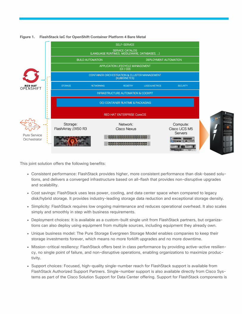
FlashStack IaC for OpenShift Container Platform 4 Bare Metal Figure 1.
This joint solution offers the following benefits:
● Consistent performance: FlashStack provides higher, more consistent performance than disk-based solu-
tions, and delivers a converged infrastructure based on all-flash that provides non-disruptive upgrades
and scalability.
● Cost savings: FlashStack uses less power, cooling, and data center space when compared to legacy
disk/hybrid storage. It provides industry-leading storage data reduction and exceptional storage density.
● Simplicity: FlashStack requires low ongoing maintenance and reduces operational overhead. It also scales
simply and smoothly in step with business requirements.
● Deployment choices: It is available as a custom-built single unit from FlashStack partners, but organiza-
tions can also deploy using equipment from multiple sources, including equipment they already own.
● Unique business model: The Pure Storage Evergreen Storage Model enables companies to keep their
storage investments forever, which means no more forklift upgrades and no more downtime.
● Mission-critical resiliency: FlashStack offers best in class performance by providing active-active resilien-
cy, no single point of failure, and non-disruptive operations, enabling organizations to maximize produc-
tivity.
● Support choices: Focused, high-quality single-number reach for FlashStack support is available from
FlashStack Authorized Support Partners. Single-number support is also available directly from Cisco Sys-
tems as part of the Cisco Solution Support for Data Center offering. Support for FlashStack components is

also available from Cisco, and Pure Storage individually and leverages TSANet for resolution of support
queries between vendors.
Like all other FlashStack solution designs, FlashStack for OCP 4 Bare Metal is configurable according to demand
and usage. Customers can purchase exactly the infrastructure they need for their current application require-
ments and can then scale-up by adding more resources to the FlashStack system or scale-out by adding more
FlashStack instances.
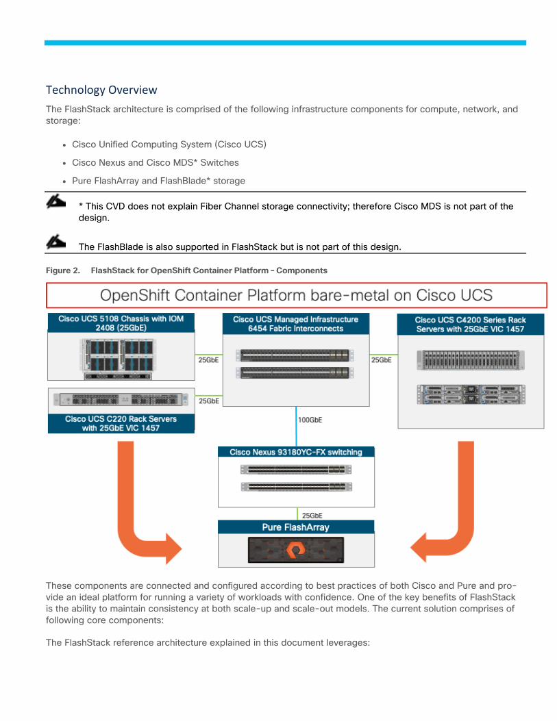
Technology Overview
The FlashStack architecture is comprised of the following infrastructure components for compute, network, and
storage:
● Cisco Unified Computing System (Cisco UCS)
● Cisco Nexus and Cisco MDS* Switches
● Pure FlashArray and FlashBlade* storage
* This CVD does not explain Fiber Channel storage connectivity; therefore Cisco MDS is not part of the
design.
The FlashBlade is also supported in FlashStack but is not part of this design.
FlashStack for OpenShift Container Platform – Components Figure 2.
These components are connected and configured according to best practices of both Cisco and Pure and pro-
vide an ideal platform for running a variety of workloads with confidence. One of the key benefits of FlashStack
is the ability to maintain consistency at both scale-up and scale-out models. The current solution comprises of
following core components:
The FlashStack reference architecture explained in this document leverages:

● Cisco UCS Manager on Cisco 4th generation 6454 Fabric Interconnects to support 10GbE, 25GbE and
100GbE connectivity from various components.
● Cisco UCS 5108 Chassis with Cisco UCS B200 M5 blade servers, Cisco UCS C220 M5 rack servers and
Cisco UCS C4200 chassis with Cisco UCS C125 M5 nodes to support Red Hat OCP 4 bare metal deploy-
ment.
● High-Speed Cisco NXOS based Nexus 93180YC-FX switching design to support up to 100GbE connec-
tivity.
● Pure FlashArray//X R3 ALL-NVMe storage with 25GbE connectivity to Cisco Nexus switching fabric.
● Red Hat OpenShift Container Platform (version 4.7)
● Pure Service Orchestrator 6.1.0
The key features and highlights for these FlashStack components are explained below.
Cisco Unified Computing System
Cisco Unified Computing System™ (Cisco UCS®) is an integrated computing infrastructure with intent-based
management to automate and accelerate deployment of all your applications, including virtualization and cloud
computing, scale-out and bare metal workloads, and in-memory analytics, as well as edge computing that sup-
ports remote and branch locations and massive amounts of data from the Internet of Things (IoT). The system is
flexible, agile, and adaptable, and the portfolio of products supported by Cisco UCS includes blade, rack, multi-
node, and storage-intensive servers; converged infrastructure; hyperconverged infrastructure (Cisco Hyper-
Flex™ systems); and solutions for the network edge such as Cisco UCS Mini and Cisco HyperFlex Edge. Cisco
UCS supports blade, rack, multinode, and storage servers in a single domain of up to 160 servers.
Cisco UCS C125 M5 Rack Servers in the Cisco UCS C4200 Series Rack Server Chassis
The Cisco UCS C125 M5 server shown in Figure 3, plugs into the Cisco UCS C4200 Rack Server Chassis.
Cisco UCS C125 M5 Rack Server Node Figure 3.
The Cisco UCS C4200 chassis extends the capabilities of the Cisco UCS portfolio in a 2-Rack-Unit (2RU) form
factor supporting up to four Cisco UCS C125 M5 Rack Server Nodes. The latest update includes support for
AMD EPYC 2 (Rome) 7002 processors validated in this design. The AMD EPYC 2 processors have higher core
density (up to 64 cores) and higher performance with an enhanced AMD Zen 2 core design. The AMD EPYC
7001 processors will continue to be offered for flexibility of customer choice. Both CPU types deliver significant
performance and efficiency gains in a compact form factor that will improve your application performance while
saving space. The Cisco UCS C4200 and the Cisco UCS C125 M5 nodes deliver outstanding levels of capability
and performance in a highly compact package, with:
● AMD EPYC 7002 (Rome) series processors, with up to 64 cores per socket, AMD EPYC 7001 (Na-
ples) series processors with up to 32 cores per socket.
● Up to 1 TB of DRAM using sixteen 64-GB DDR4 DIMMs for 2-socket CPU configuration (eight
DIMMs/memory channels per CPU).
SS
● 3200 MHz 16G/32G/64G DIMMs for AMD EPYC 7002 (Rome) CPUs and 2666 MHz 16G/32G/64G DIMMs
for AMD EPYC 7001 CPUs.
● Optional dual SD cards or M.2 modular storage for increased storage or boot drive capacity.
● Support for Cisco’s fourth-generation PCIe Virtual Interface Card (VIC) 1455 offering up to 100 Gbps of
I/O throughput with Cisco UCS 6454 FI.
For more information about the Cisco UCS C125 M5 Rack Server Nodes in the Cisco UCS C4200 Rack Server
Chassis, see: https://www.cisco.com/c/en/us/products/collateral/servers-unified-computing/ucs-c4200-
series-rack-server-chassis/datasheet-c78-740839.html.
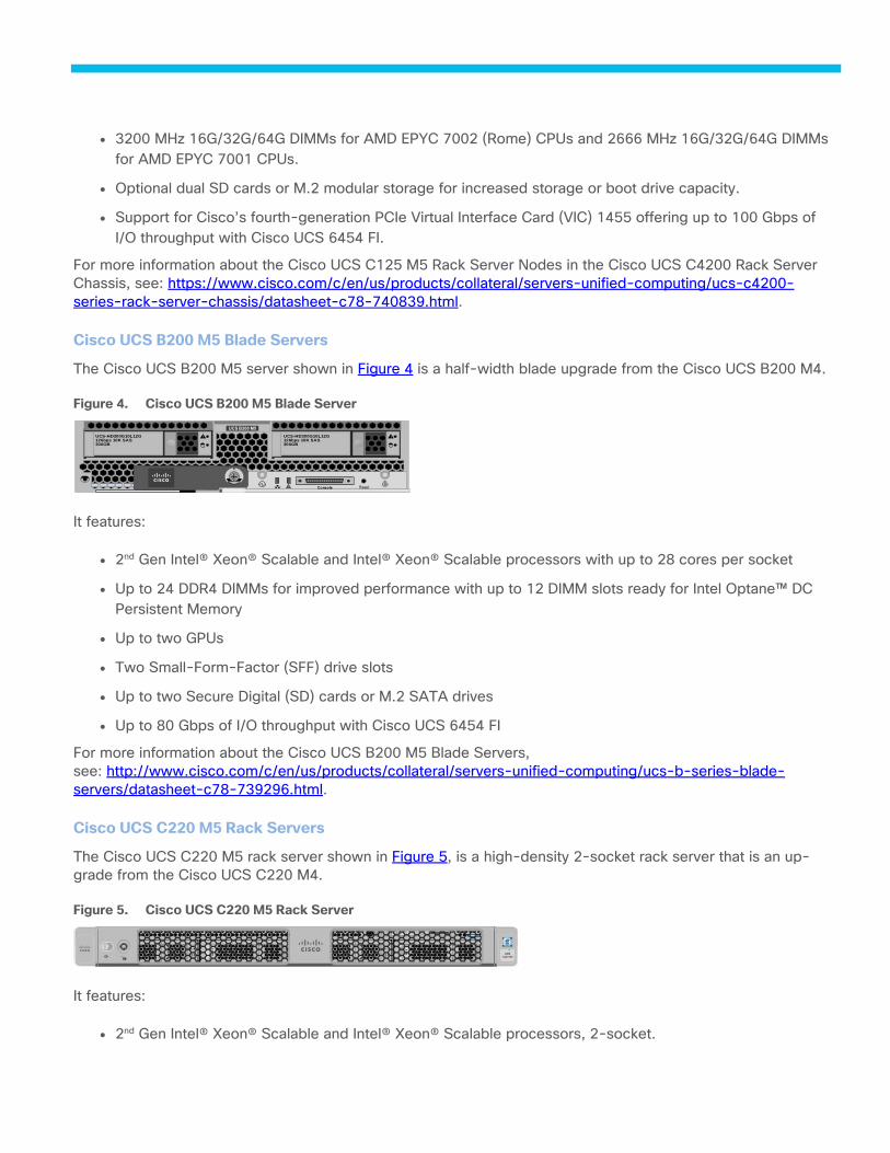
Cisco UCS B200 M5 Blade Servers
The Cisco UCS B200 M5 server shown in Figure 4 is a half-width blade upgrade from the Cisco UCS B200 M4.
Cisco UCS B200 M5 Blade Server Figure 4.
It features:
● 2nd Gen Intel® Xeon® Scalable and Intel® Xeon® Scalable processors with up to 28 cores per socket
● Up to 24 DDR4 DIMMs for improved performance with up to 12 DIMM slots ready for Intel Optane™ DC
Persistent Memory
● Up to two GPUs
● Two Small-Form-Factor (SFF) drive slots
● Up to two Secure Digital (SD) cards or M.2 SATA drives
● Up to 80 Gbps of I/O throughput with Cisco UCS 6454 FI
For more information about the Cisco UCS B200 M5 Blade Servers,
see: http://www.cisco.com/c/en/us/products/collateral/servers-unified-computing/ucs-b-series-blade-
servers/datasheet-c78-739296.html.
Cisco UCS C220 M5 Rack Servers
The Cisco UCS C220 M5 rack server shown in Figure 5, is a high-density 2-socket rack server that is an up-
grade from the Cisco UCS C220 M4.
Cisco UCS C220 M5 Rack Server Figure 5.
It features:
● 2nd Gen Intel® Xeon® Scalable and Intel® Xeon® Scalable processors, 2-socket.
! ResetConsole
UCS-HD300G10L12G126bps 10K SAS300GB
!
UCS B200 M5
UCS-HD300G10L12G126bps 10K SAS300GB
!
UCS
C220 M5
S321
2 T
BH
D2
T7
KL6
GN
SA
TA
HD
D
X2 T
BH
D2
T7
KL6
GN
SA
TA
HD
D
X3.2
TB
NV
ME
HY
H3
20
0
X 3.2
TB
NV
ME
HY
H3
20
0
X

● Up to 24 DDR4 DIMMs for improved performance with up to 12 DIMM slots ready for Intel Optane™ DC
Persistent Memory.
● Up to 10 Small-Form-Factor (SFF) 2.5-inch drives or 4 Large-Form-Factor (LFF) 3.5-inch drives (77 TB
storage capacity with all NVMe PCIe SSDs).
● Support for 12-Gbps SAS modular RAID controller in a dedicated slot, leaving the remaining PCIe Genera-
tion 3.0 slots available for other expansion cards.
● Modular LAN-On-Motherboard (mLOM) slot that can be used to install a Cisco UCS Virtual Interface Card
(VIC) without consuming a PCIe slot.
● Dual embedded Intel x550 10GBASE-T LAN-On-Motherboard (LOM) ports.
● Up to 100 Gbps of I/O throughput with Cisco UCS 6454 FI.
For more information about the Cisco UCS B200 M5 Blade Servers,
see: https://www.cisco.com/c/en/us/products/collateral/servers-unified-computing/ucs-c-series-rack-
servers/datasheet-c78-739281.html.
Cisco UCS 6400 series Fabric Interconnects
The Cisco UCS Fabric Interconnects (FIs) provide a single point for connectivity and management for the entire
Cisco UCS system. Typically deployed as an active-active pair, the system’s FIs integrate all components into a
single, highly available management domain controlled by the Cisco UCS Manager. Cisco UCS FIs provide a sin-
gle unified fabric for the system, with low-latency, lossless, cut-through switching that supports LAN, SAN and
management traffic using a single set of cables.
The Cisco UCS 6454 (Figure 6) deployed for this validation, provides the management and communication
backbone for the Cisco UCS B-Series Blade Servers, Cisco UCS 5108 B-Series Server Chassis and Cisco UCS
Managed C-Series Rack Servers. All servers attached to the Cisco UCS 6454 Fabric Interconnect become part
of a single, highly available management domain. In addition, by supporting a unified fabric, the Cisco UCS 6454
provides both the LAN and SAN connectivity for all servers within its domain. The Cisco UCS 6454 supports de-
terministic, low-latency, line-rate 10/25/40/100 Gigabit Ethernet ports, a switching capacity of 3.82 Tbps, and
320 Gbps bandwidth between FI 6454 and IOM 2208 per 5108 blade chassis, independent of packet size and
enabled services.
Cisco UCS 6400 Series Fabric Interconnect Figure 6.
Cisco UCS 2408 Fabric Extender
The Cisco UCS 2408 connects the I/O fabric between the Cisco UCS 6454 Fabric Interconnect and the Cisco
UCS 5100 Series Blade Server Chassis, enabling a lossless and deterministic converged fabric to connect all
blades and chassis together.
The Cisco UCS 2408 Fabric Extender has eight 25-Gigabit Ethernet, FCoE-capable, Small Form-Factor Plugga-
ble (SFP28) ports that connect the blade chassis to the fabric interconnect. Each Cisco UCS 2408 provides 10-
Gigabit Ethernet ports connected through the midplane to each half-width slot in the chassis, giving it a total 32
CISCO UCS-FI-6454
49 50 51 52 53 541 2 3 4 5 6 7 8 9 10 11 12 13 14 15 16
ENV
STS
BCN
17 18 19 20 21 22 23 24 25 26 27 28 29 30 31 32 33 34 35 36 37 38 39 40 41 42 43 44 45 46 47 48
10G interfaces to UCS blades. Typically configured in pairs for redundancy, two fabric extenders provide up to
400 Gbps of I/O from FI 6400's to 5108 chassis.
Cisco UCS 1400 Series Virtual Interface Cards (VICs)
Cisco VICs support Cisco SingleConnect technology, which provides an easy, intelligent, and efficient way to
connect and manage computing in your data center. Cisco SingleConnect unifies LAN, SAN, and systems man-
agement into one simplified link for rack servers and blade servers. This technology reduces the number of net-
work adapters, cables, and switches needed and radically simplifies the network, reducing complexity. Cisco
VICs can support 256 Express (PCIe) virtual devices, either virtual Network Interface Cards (vNICs) or virtual
Host Bus Adapters (vHBAs), with a high rate of I/O Operations Per Second (IOPS), support for lossless Ethernet,
and 10/25/40/100-Gbps connection to servers. The PCIe Generation 3 x16 interface helps ensure optimal
bandwidth to the host for network-intensive applications, with a redundant path to the fabric interconnect. Cisco
VICs support NIC teaming with fabric failover for increased reliability and availability. In addition, it provides a
policy-based, stateless, agile server infrastructure for your data center.
The Cisco VIC 1400 series is designed exclusively for the M5 generation of Cisco UCS B-Series Blade Servers
and Cisco UCS C-Series Rack Servers. The adapters are capable of supporting 10/25/40/100-Gigabit Ethernet
and Fibre Channel over Ethernet (FCoE). It incorporates Cisco’s next-generation Converged Network Adapter
(CNA) technology and offers a comprehensive feature set, providing investment protection for future feature
software releases.
Cisco UCS Management
While Cisco UCS is stateless, programmable infrastructure, the Cisco UCS unified API is how management tools
program it. This enables the tools to help guarantee consistent, error-free, policy-based alignment of server
personalities with workloads. Through automation, transforming the server and networking components of your
infrastructure into a complete solution is fast and error-free because programmability eliminates the error-prone
manual configuration of servers and integration into solutions. Server, network, and storage administrators are
now free to focus on strategic initiatives rather than spending their time performing tedious tasks.
Cisco UCS Manager
Cisco UCS® Manager (UCSM) provides unified, integrated management for all software and hardware compo-
nents in Cisco UCS manages a single domain through an intuitive HTML 5-based GUI. is embedded in each fab-
ric interconnect. Running in a redundant, high-availability configuration, it creates a single, self-aware, self-
integrating unified system that recognizes and integrates components as they are added to the system. It quickly
and accurately configures computing, network, storage, and storage-access resources to reduce the chance of
errors that can cause downtime. Its role and policy-based approach helps organizations more easily align poli-
cies and configurations with workloads. While Cisco UCS Manager requires an “always on” connection, our oth-
er tools are evolving to manage systems to which they are not continuously connected.
Cisco Intersight Software-as-a-Service Management
This platform has the broadest scope of the Cisco UCS management tools. It enables programming the infra-
structure by automating configuration and management, but it goes the farthest in integrating with outside ser-
vices and tools.
Accessed from the cloud or through an optional local management appliance, Intersight provides a single inter-
face from which you can undertake lifecycle management of your servers and Cisco Nexus® switches whether
they are in a core data center or at the network edge. New features are continually integrated, and you can keep
up to date on the most current enhancements by visiting cisco.com/go/intersight.
The Intersight platform enables you to configure the identity, personality, and connectivity of blade and rack
servers. It provides access to automated deployment for entities such as Cisco HyperFlex clusters, and it can
automate and support large-scale edge deployments. Intersight provides the following additional capabilities
that are complementary to the basic deployment and configuration features:
● Global dashboard and inventory - When you manage your infrastructure with Cisco Intersight, you can
view a global dashboard that gives you overall server status and enables you to drill down to view individ-
ual components (such as disk drives) With a global inventory of your devices, it’s easy to track the location
of each of your assets.
● Cisco TAC - With Intersight’s integration with Cisco TAC, you can quickly remediate problems because
expertise and information can flow seamlessly between Intersight and your Cisco support center. The sys-
tem can open cases and upload supporting documentation for fast resolution. It maintains the status of
your contracts and licenses so that you can administer them from the same interface.
● Recommendation engine - This feature gives you recommendations on configurations and help you im-
plement best practices. Intersight has insight into your operating system and driver versions. It can use
these to validate that your implementations are supported by Cisco’s Hardware Configuration List (HCL).
DevOps and Tool Support
The Cisco UCS unified API is of great benefit to developers and administrators who want to treat physical infra-
structure the way they treat other application services, using processes that automatically provision or change IT
resources. Similarly, your IT staff needs to provision, configure, and monitor physical and virtual resources; au-
tomate routine activities; and rapidly isolate and resolve problems. The Cisco UCS unified API integrates with
DevOps management tools and processes and enables you to easily adopt DevOps methodologies.
Pure Storage FlashArray with Intersight
The Cisco Intersight Premier edition offers private-cloud Infrastructure-as-a-Service (IaaS) orchestration across
Cisco UCS, HyperFlex, and third-party endpoints including VMWare vCenter and Pure Storage. This feature,
called Cisco Intersight Orchestrator, enables you to create and execute workflows in Cisco Intersight. For exam-
ple, provisioning a Pure Storage FlashArray or deploying a new virtual machine from a template could involve
multiple tasks, but with Cisco Intersight Orchestrator, the administrator has a workflow designer to visualize a
workflow definition and monitor the execution of that workflow on any infrastructure element.
Cisco Workload Optimization Manager
Cisco Workload Optimization Manager (CWOM) is a real-time decision engine that drives continuous health in
the IT environment. Its intelligent software constantly analyzes workload consumption, costs, and compliance
constraints. It assures application performance by giving workloads the resources they need when required.
CWOM provides specific real-time actions that ensure workloads get the resources they need for:
● Planning
● Placement
● Reports
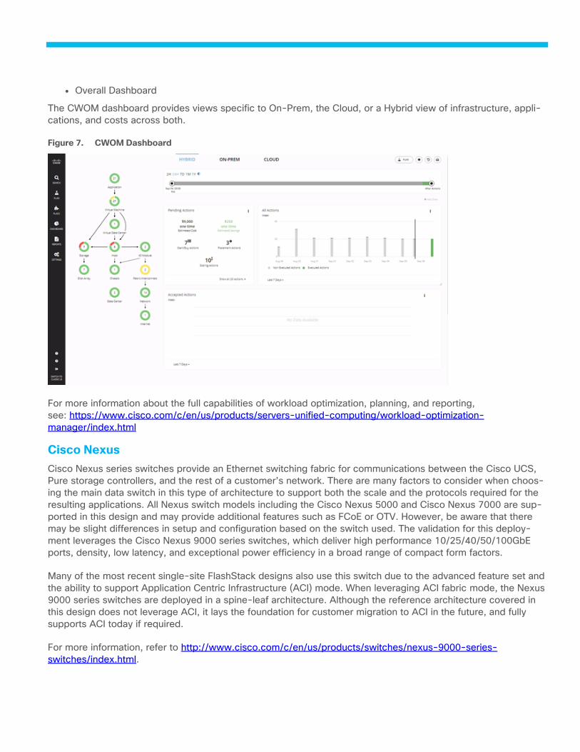
● Overall Dashboard
The CWOM dashboard provides views specific to On-Prem, the Cloud, or a Hybrid view of infrastructure, appli-
cations, and costs across both.
CWOM Dashboard Figure 7.
For more information about the full capabilities of workload optimization, planning, and reporting,
see: https://www.cisco.com/c/en/us/products/servers-unified-computing/workload-optimization-
manager/index.html
Cisco Nexus
Cisco Nexus series switches provide an Ethernet switching fabric for communications between the Cisco UCS,
Pure storage controllers, and the rest of a customer’s network. There are many factors to consider when choos-
ing the main data switch in this type of architecture to support both the scale and the protocols required for the
resulting applications. All Nexus switch models including the Cisco Nexus 5000 and Cisco Nexus 7000 are sup-
ported in this design and may provide additional features such as FCoE or OTV. However, be aware that there
may be slight differences in setup and configuration based on the switch used. The validation for this deploy-
ment leverages the Cisco Nexus 9000 series switches, which deliver high performance 10/25/40/50/100GbE
ports, density, low latency, and exceptional power efficiency in a broad range of compact form factors.
Many of the most recent single-site FlashStack designs also use this switch due to the advanced feature set and
the ability to support Application Centric Infrastructure (ACI) mode. When leveraging ACI fabric mode, the Nexus 9000 series switches are deployed in a spine-leaf architecture. Although the reference architecture covered in
this design does not leverage ACI, it lays the foundation for customer migration to ACI in the future, and fully
supports ACI today if required.
For more information, refer to http://www.cisco.com/c/en/us/products/switches/nexus-9000-series-
switches/index.html.

This FlashStack design deploys a single pair of Cisco Nexus 93180YC-FX top-of-rack switches (Figure 8) within
each placement, using the traditional standalone mode running NX-OS.
Cisco Nexus 93180YC-FX Figure 8.
Pure Storage FlashArray
The Pure Storage FlashArray family delivers purpose-built, software-defined all-flash power and reliability for
businesses of every size. FlashArray is all-flash enterprise storage that is up to 10X faster, more space and
power efficient, more reliable, and far simpler than other available solutions. Critically, FlashArray also costs less,
with a TCO that's typically 50% lower than traditional performance disk arrays.
At the top of the FlashArray line is FlashArray//X – the first mainstream, 100% NVMe, enterprise-class all-flash
array. //X represents a higher performance tier for mission-critical databases, top-of-rack flash deployments,
and Tier 1 application consolidation. //X, at 1PB in 3U, with hundred-microsecond range latency and GBs of
bandwidth, delivers an unprecedented level of performance density that makes possible previously unattainable
levels of consolidation.
FlashArray//X is ideal for cost-effective consolidation of everything on flash. Whether accelerating a single data-
base, scaling virtual desktop environments, or powering an all-flash cloud, there is an //X model that fits your
needs.
Pure Storage FlashArray//X R3 Figure 9.
Purity for FlashArray (Purity//FA 6)
At the heart of every FlashArray is Purity Operating Environment software. Purity//FA6 implements advanced da-
ta reduction, storage management, and flash management features, enabling organizations to enjoy Tier 1 data
services for all workloads, proven 99.9999% availability over two years (inclusive of maintenance and genera-
tional upgrades), completely non-disruptive operations, 2X better data reduction versus alternative all-flash so-
lutions, and – with FlashArray//X – the power and efficiency of DirectFlash™. Moreover, Purity includes enter-
prise-grade data security, comprehensive data protection options, and complete business continuity via Active-
Cluster multi-site stretch cluster. All these features are included with every array.
CISCO NEXUS N9K-C93180YC-EX
53 5451 5249 501 2 3 4 5 6 7 8 9 10 11 12 13 14 15 16 17 18 19 20 21 22 23 24 25 26 27 28 29 30 31 32 33 34 35 36 37 38 39 40 41 42 43 44 45 46 47 48
BCN
STS
ENV
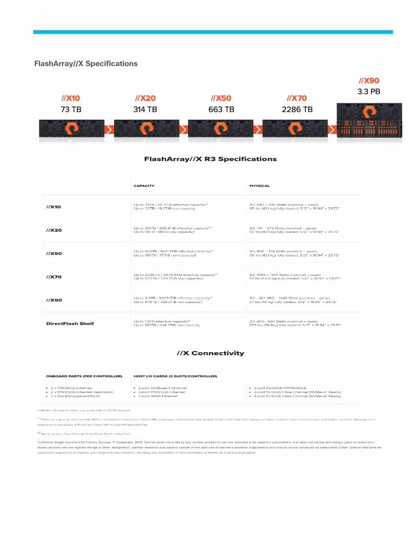
FlashArray//X Specifications
** Effective capacity assumes HA, RAID, and metadata overhead, GB-to-GiB conversion, and includes the bene-
fit of data reduction with always-on inline deduplication, compression, and pattern removal. Average data re-
duction is calculated at 5-to-1 and does not include thin provisioning or snapshots.
† Array accepts Pure Storage DirectFlash Shelf and/or Pure Storage SAS-based expansion shelf.
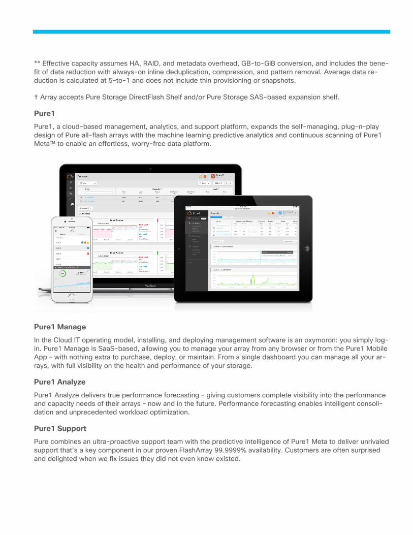
Pure1
Pure1, a cloud-based management, analytics, and support platform, expands the self-managing, plug-n-play
design of Pure all-flash arrays with the machine learning predictive analytics and continuous scanning of Pure1
Meta™ to enable an effortless, worry-free data platform.
Pure1 Manage
In the Cloud IT operating model, installing, and deploying management software is an oxymoron: you simply log-
in. Pure1 Manage is SaaS-based, allowing you to manage your array from any browser or from the Pure1 Mobile
App – with nothing extra to purchase, deploy, or maintain. From a single dashboard you can manage all your ar-
rays, with full visibility on the health and performance of your storage.
Pure1 Analyze
Pure1 Analyze delivers true performance forecasting – giving customers complete visibility into the performance
and capacity needs of their arrays – now and in the future. Performance forecasting enables intelligent consoli-
dation and unprecedented workload optimization.
Pure1 Support
Pure combines an ultra-proactive support team with the predictive intelligence of Pure1 Meta to deliver unrivaled
support that’s a key component in our proven FlashArray 99.9999% availability. Customers are often surprised
and delighted when we fix issues they did not even know existed.

Pure1 META
The foundation of Pure1 services, Pure1 Meta is global intelligence built from a massive collection of storage
array health and performance data. By continuously scanning call-home telemetry from Pure’s installed base,
Pure1 Meta uses machine learning predictive analytics to help resolve potential issues and optimize workloads.
The result is both a white glove customer support experience and breakthrough capabilities like accurate per-
formance forecasting.
Meta is always expanding and refining what it knows about array performance and health, moving the Data Plat-
form toward a future of self-driving storage.
Pure Service Orchestrator
Pure Service Orchestrator is designed to provide a similar experience to your developers that they expect they
can only get from the public cloud. For more information, go to: https://github.com/purestorage/pso-csi.
Service Orchestrator integrates seamlessly with the container orchestration frameworks (Kubernetes) and func-
tions as the control plane virtualization layer. This enables your containerized environment to move away from
consuming storage-as-a-device to consuming storage-as-a-service, as follows:
● Smart Policy Provisioning: Delivers storage on demand via policy. Service Orchestrator makes the best
provisioning decision for each storage request by assessing multiple factors such as performance load,
capacity utilization, and health of a given storage system in real-time. Building upon
the effortless foundation of Pure Storage, Service Orchestrator delivers an effortless experience and frees
the Container Admin from writing complex pod definitions. For example, the default storage requests to
Service Orchestrator are as simple as specifying the storage size. No size specified, no problem! Service
Orchestrator will service those requests too.
● Elastic Scaling: Scale’s container storage across multiple FlashArray, FlashBlade™ or mix of both systems,
supports mix of file and block, and delivers the flexibility to have varied configurations for each storage
system that is part of the service. With the astonishing ease of expanding your storage service with a sin-
gle command, you can start small and scale storage seamlessly and quickly as the needs of your contain-
erized environments grow.
● Transparent Recovery: Self-heals to ensure your services stay robust. For example, Service Orchestrator
prevents accidental data corruption by ensuring a storage volume is bound to a single persistent volume
claim at any given time. If Kubernetes master sends a request to attach the same volume to another Ku-
bernetes node, Service Orchestrator will disconnect the volume from the original Kubernetes node first
before attaching it to a new Kubernetes node. This behavior ensures that if a Kubernetes cluster “split-
brain” condition occurs (where the Kubernetes master and node become out of sync due to loss of com-
munication), simultaneous I/O to the same storage volume which can corrupt data is prevented.
For more information about Pure Service Orchestrator and to access the installation repository,
see: https://github.com/purestorage/pso-csi
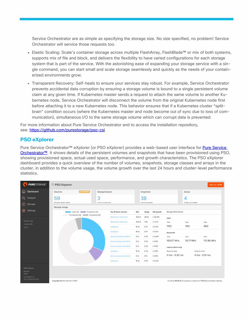
PSO eXplorer
Pure Service Orchestrator™ eXplorer (or PSO eXplorer) provides a web-based user interface for Pure Service
Orchestrator™. It shows details of the persistent volumes and snapshots that have been provisioned using PSO,
showing provisioned space, actual used space, performance, and growth characteristics. The PSO eXplorer
dashboard provides a quick overview of the number of volumes, snapshots, storage classes and arrays in the
cluster, in addition to the volume usage, the volume growth over the last 24 hours and cluster-level performance
statistics.
For more information about PSO eXplorer and to access the installation repository, go
to: https://github.com/PureStorage-OpenConnect/pso-explorer.
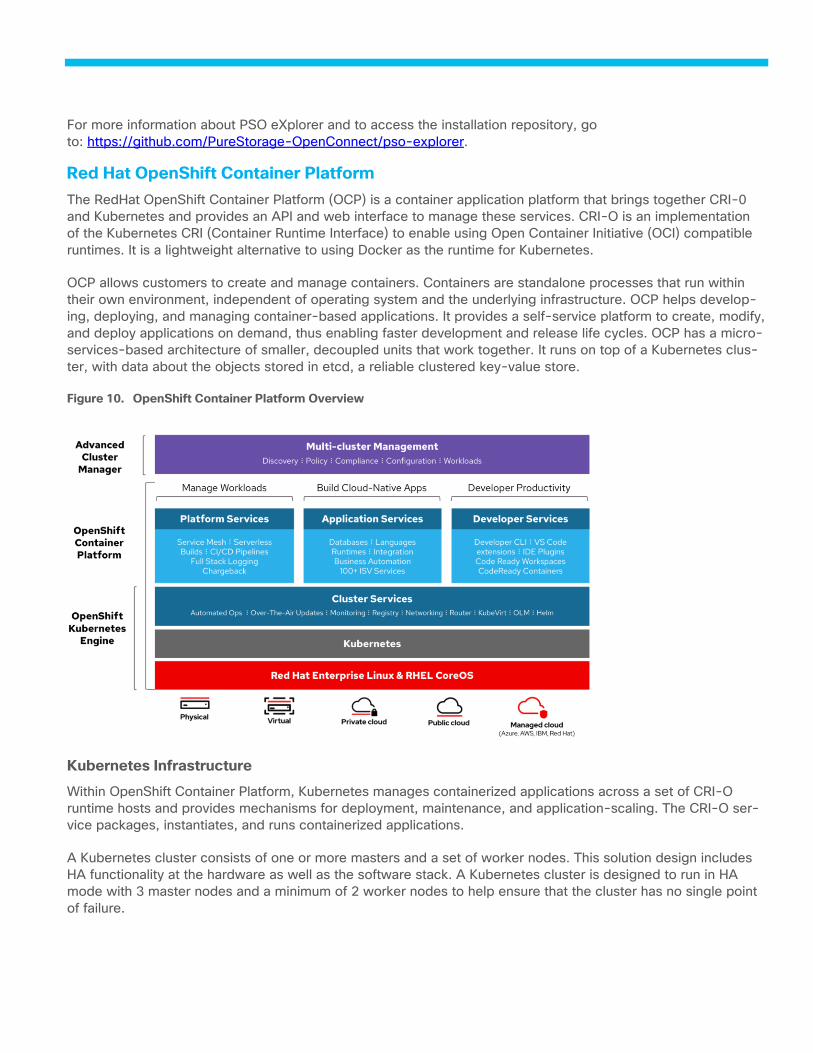
Red Hat OpenShift Container Platform
The RedHat OpenShift Container Platform (OCP) is a container application platform that brings together CRI-0
and Kubernetes and provides an API and web interface to manage these services. CRI-O is an implementation
of the Kubernetes CRI (Container Runtime Interface) to enable using Open Container Initiative (OCI) compatible
runtimes. It is a lightweight alternative to using Docker as the runtime for Kubernetes.
OCP allows customers to create and manage containers. Containers are standalone processes that run within
their own environment, independent of operating system and the underlying infrastructure. OCP helps develop-
ing, deploying, and managing container-based applications. It provides a self-service platform to create, modify,
and deploy applications on demand, thus enabling faster development and release life cycles. OCP has a micro-
services-based architecture of smaller, decoupled units that work together. It runs on top of a Kubernetes clus-
ter, with data about the objects stored in etcd, a reliable clustered key-value store.
OpenShift Container Platform Overview Figure 10.
Kubernetes Infrastructure
Within OpenShift Container Platform, Kubernetes manages containerized applications across a set of CRI-O
runtime hosts and provides mechanisms for deployment, maintenance, and application-scaling. The CRI-O ser-
vice packages, instantiates, and runs containerized applications.
A Kubernetes cluster consists of one or more masters and a set of worker nodes. This solution design includes
HA functionality at the hardware as well as the software stack. A Kubernetes cluster is designed to run in HA
mode with 3 master nodes and a minimum of 2 worker nodes to help ensure that the cluster has no single point
of failure.
Red Hat Core OS
OpenShift Container Platform uses Red Hat Enterprise Linux CoreOS (RHCOS), a container-oriented operating
system that combines some of the best features and functions of the CoreOS and Red Hat Atomic Host operat-
ing systems. RHCOS is specifically designed for running containerized applications from OpenShift Container
Platform and works with new tools to provide fast installation, Operator-based management, and simplified up-
grades.
RHCOS includes:
● Ignition, which OpenShift Container Platform uses as a first boot system configuration for initially bringing
up and configuring machines.
● CRI-O, a Kubernetes native container runtime implementation that integrates closely with the operating
system to deliver an efficient and optimized Kubernetes experience. CRI-O provides facilities for running,
stopping, and restarting containers. It fully replaces the Docker Container Engine, which was used in
OpenShift Container Platform 3.
● Kubelet, the primary node agent for Kubernetes that is responsible for launching and monitoring contain-
ers.
RHCOS was used on all control plane and worker nodes to support automated OCP 4 deployment.
Red Hat Ansible
Red Hat Ansible Automation helps Red Hat OpenShift Container Platform users create and run reusable infra-
structure code and automate provisioning tasks for infrastructure components.
Ansible is simple and powerful, allowing users to easily manage various physical devices within FlashStack- in-
cluding the provisioning of Cisco UCS bare metal servers, Cisco Nexus switches and Pure FlashArray storage.
Using Ansible’s Playbook-based automation is easy and integrates into your current provisioning infrastructure.
Finally, Ansible also provides robust container and native Kubernetes management, expanding to Red Hat
OpenShift Container Platform and other container technologies.

Solution Design
The FlashStack for Red Hat OpenShift Container Platform provides an end-to-end architecture with Cisco and
Pure technologies that demonstrate support for OCP workloads with high availability and server redundancy. The
architecture consists of OCP Bare Metal cluster deployed on Cisco UCS M5 servers within FlashStack infrastruc-
ture, with the Cisco UCS servers and Pure FlashArray storage attached to the Cisco Nexus 93180YC-FX switch-
es in NXOS mode.
Figure 11 illustrates a base design. Each of the components can be scaled easily to support specific business
requirements. For example, additional OCP nodes can be deployed to scale the OCP environment to increase
compute capacity, additional storage controllers or disk shelves can be deployed to improve I/O capability and
throughput.
The solution was validated using Cisco UCS B200 M5, C220 M5 and C125 servers to show the versatility
of the Cisco UCS platform. Customers can choose to deploy OCP on just the Cisco UCS B-Series serv-
ers, the Cisco UCS C-Series or Cisco UCS C125 servers depending on their requirements.
Figure 11 provides a high-level overview of the FlashStack for OCP cluster architecture.
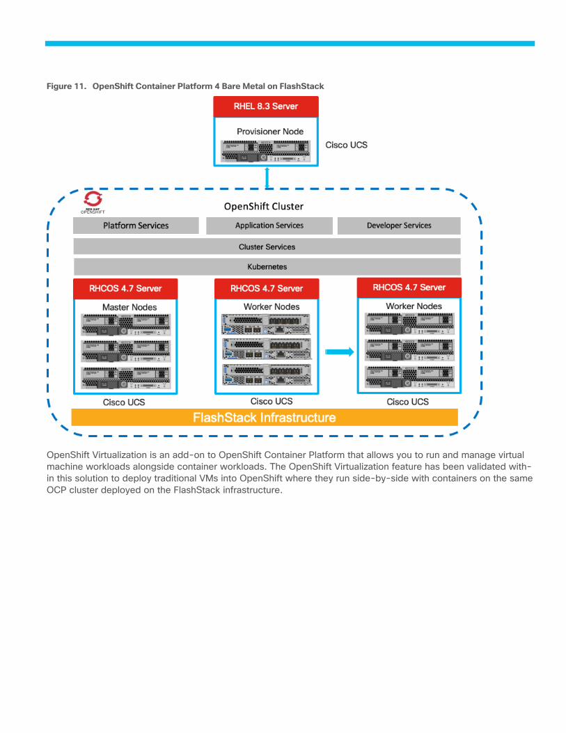
OpenShift Container Platform 4 Bare Metal on FlashStack Figure 11.
OpenShift Virtualization is an add-on to OpenShift Container Platform that allows you to run and manage virtual
machine workloads alongside container workloads. The OpenShift Virtualization feature has been validated with-
in this solution to deploy traditional VMs into OpenShift where they run side-by-side with containers on the same
OCP cluster deployed on the FlashStack infrastructure.
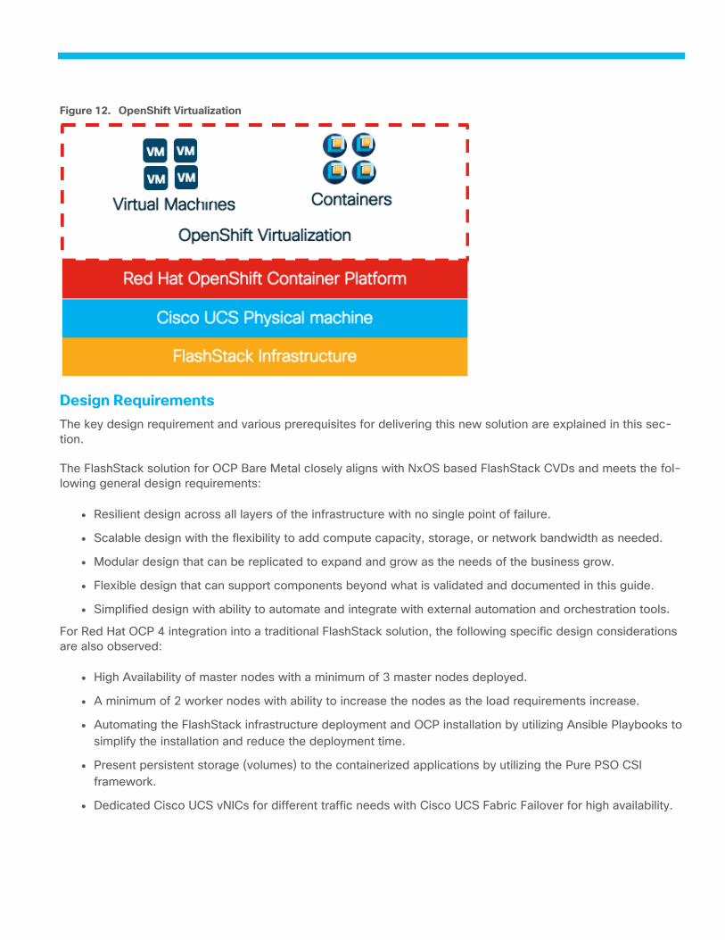
OpenShift Virtualization Figure 12.
Design Requirements
The key design requirement and various prerequisites for delivering this new solution are explained in this sec-
tion.
The FlashStack solution for OCP Bare Metal closely aligns with NxOS based FlashStack CVDs and meets the fol-
lowing general design requirements:
● Resilient design across all layers of the infrastructure with no single point of failure.
● Scalable design with the flexibility to add compute capacity, storage, or network bandwidth as needed.
● Modular design that can be replicated to expand and grow as the needs of the business grow.
● Flexible design that can support components beyond what is validated and documented in this guide.
● Simplified design with ability to automate and integrate with external automation and orchestration tools.
For Red Hat OCP 4 integration into a traditional FlashStack solution, the following specific design considerations
are also observed:
● High Availability of master nodes with a minimum of 3 master nodes deployed.
● A minimum of 2 worker nodes with ability to increase the nodes as the load requirements increase.
● Automating the FlashStack infrastructure deployment and OCP installation by utilizing Ansible Playbooks to
simplify the installation and reduce the deployment time.
● Present persistent storage (volumes) to the containerized applications by utilizing the Pure PSO CSI
framework.
● Dedicated Cisco UCS vNICs for different traffic needs with Cisco UCS Fabric Failover for high availability.
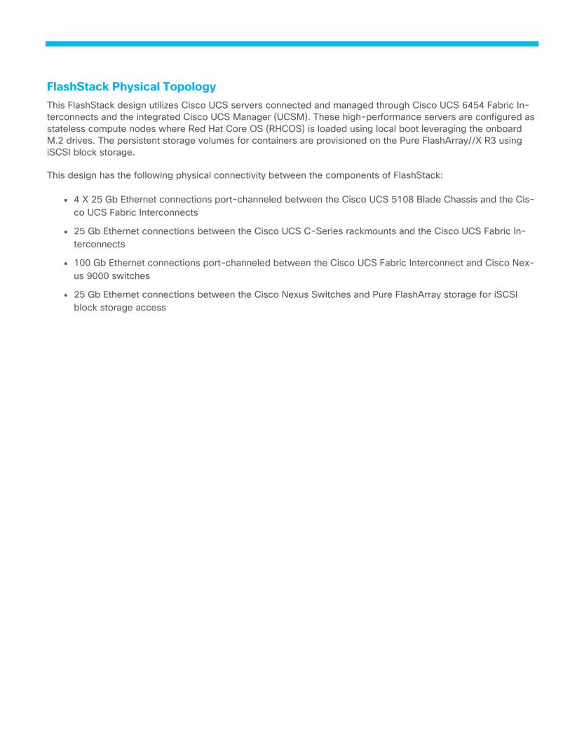
FlashStack Physical Topology
This FlashStack design utilizes Cisco UCS servers connected and managed through Cisco UCS 6454 Fabric In-
terconnects and the integrated Cisco UCS Manager (UCSM). These high-performance servers are configured as
stateless compute nodes where Red Hat Core OS (RHCOS) is loaded using local boot leveraging the onboard
M.2 drives. The persistent storage volumes for containers are provisioned on the Pure FlashArray//X R3 using
iSCSI block storage.
This design has the following physical connectivity between the components of FlashStack:
● 4 X 25 Gb Ethernet connections port-channeled between the Cisco UCS 5108 Blade Chassis and the Cis-
co UCS Fabric Interconnects
● 25 Gb Ethernet connections between the Cisco UCS C-Series rackmounts and the Cisco UCS Fabric In-
terconnects
● 100 Gb Ethernet connections port-channeled between the Cisco UCS Fabric Interconnect and Cisco Nex-
us 9000 switches
● 25 Gb Ethernet connections between the Cisco Nexus Switches and Pure FlashArray storage for iSCSI
block storage access
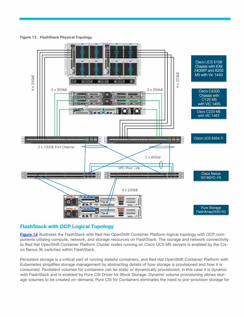
FlashStack Physical Topology Figure 13.
FlashStack with OCP Logical Topology
Figure 14 illustrates the FlashStack with Red Hat OpenShift Container Platform logical topology with OCP com-
ponents utilizing compute, network, and storage resources on FlashStack. The storage and network connectivity
to Red Hat OpenShift Container Platform Cluster nodes running on Cisco UCS M5 servers is enabled by the Cis-
co Nexus 9k switches within FlashStack.
Persistent storage is a critical part of running stateful containers, and Red Hat OpenShift Container Platform with
Kubernetes simplifies storage management by abstracting details of how storage is provisioned and how it is
consumed. Persistent volumes for containers can be static or dynamically provisioned, in this case it is dynamic
with FlashStack and is enabled by Pure CSI Driver for Block Storage. Dynamic volume provisioning allows stor-
age volumes to be created on-demand, Pure CSI for Containers eliminates the need to pre-provision storage for
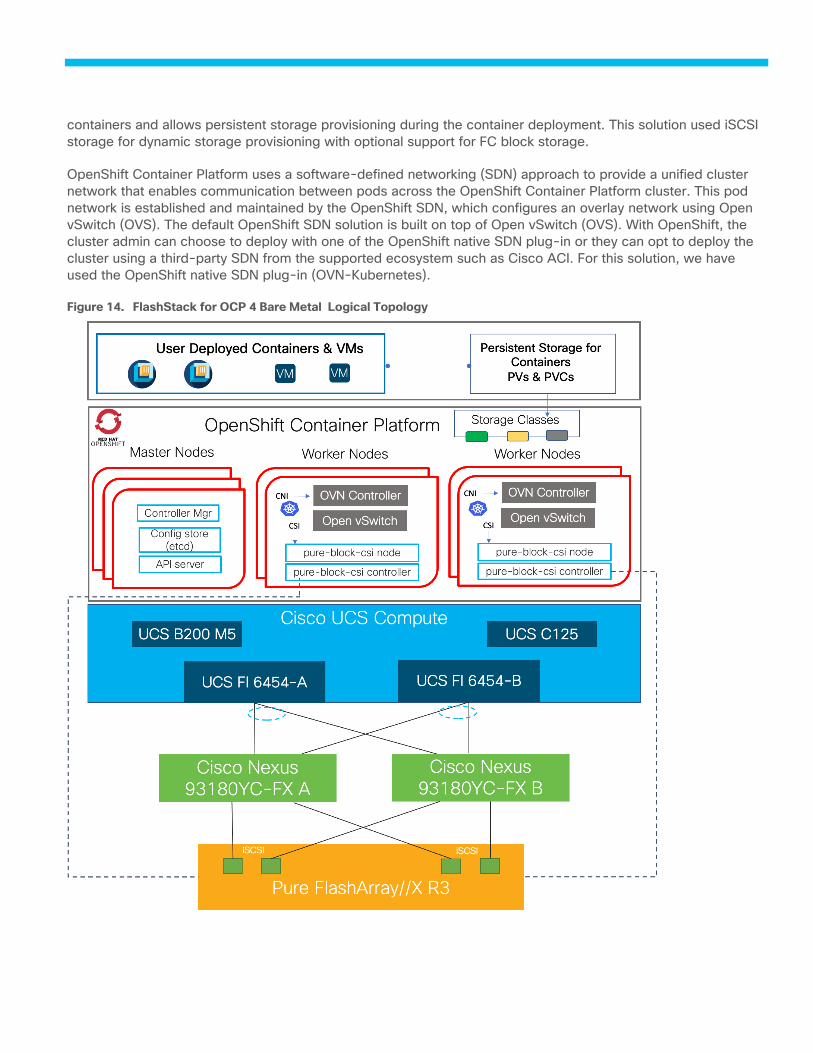
containers and allows persistent storage provisioning during the container deployment. This solution used iSCSI
storage for dynamic storage provisioning with optional support for FC block storage.
OpenShift Container Platform uses a software-defined networking (SDN) approach to provide a unified cluster
network that enables communication between pods across the OpenShift Container Platform cluster. This pod
network is established and maintained by the OpenShift SDN, which configures an overlay network using Open
vSwitch (OVS). The default OpenShift SDN solution is built on top of Open vSwitch (OVS). With OpenShift, the
cluster admin can choose to deploy with one of the OpenShift native SDN plug-in or they can opt to deploy the
cluster using a third-party SDN from the supported ecosystem such as Cisco ACI. For this solution, we have
used the OpenShift native SDN plug-in (OVN-Kubernetes).
FlashStack for OCP 4 Bare Metal Logical Topology Figure 14.

FlashStack Network Connectivity and Design
The Layer 2 network connection to each Fabric Interconnect is implemented as Virtual Port Channels (vPC) from
the upstream Nexus Switches. In the switching environment, the vPC provides the following benefits:
● Allows a single device to use a Port Channel across two upstream devices
● Eliminates Spanning Tree Protocol blocked ports and use all available uplink bandwidth
● Provides a loop-free topology
● Provides fast convergence if either one of the physical links or a device fails
● Helps ensure high availability of the network
The upstream network switches can connect to the Cisco UCS 6454 Fabric Interconnects using 10G, 25G, 40G,
or 100G port speeds. In this design, both the 25GB and 100G ports were tested for the virtual port channels. In
the iSCSI design, this would also transport the storage traffic between the UCS servers and the FlashArray//X
R3.
Network Connectivity – vPC Enabled Connections Figure 15.
FlashStack Compute Connectivity
The FlashStack compute design supports both Cisco UCS B-Series and C-Series deployments including the
Cisco UCS C125 server nodes. Cisco UCS supports the OpenShift environment by providing robust, highly avail-
able, and integrated compute resources centrally managed from Cisco UCS Manager in the Enterprise or from
Cisco Intersight Software as a Service (SaaS) in the cloud. In this validation effort, multiple Cisco UCS B-Series
and C-Series servers are booted from local M.2 SATA SSDs, these drives are configured in Raid 1 using the
Cisco Boot Optimized M.2 Raid Controller. The servers have access to iSCSI storage for persistent storage vol-
umes presented from the Pure FlashArray.
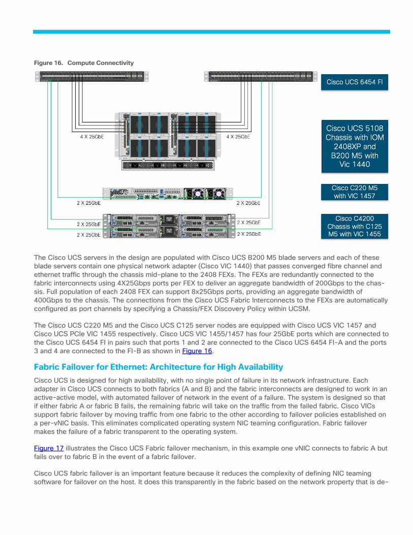
Compute Connectivity Figure 16.
The Cisco UCS servers in the design are populated with Cisco UCS B200 M5 blade servers and each of these
blade servers contain one physical network adapter (Cisco VIC 1440) that passes converged fibre channel and
ethernet traffic through the chassis mid-plane to the 2408 FEXs. The FEXs are redundantly connected to the
fabric interconnects using 4X25Gbps ports per FEX to deliver an aggregate bandwidth of 200Gbps to the chas-
sis. Full population of each 2408 FEX can support 8x25Gbps ports, providing an aggregate bandwidth of
400Gbps to the chassis. The connections from the Cisco UCS Fabric Interconnects to the FEXs are automatically
configured as port channels by specifying a Chassis/FEX Discovery Policy within UCSM.
The Cisco UCS C220 M5 and the Cisco UCS C125 server nodes are equipped with Cisco UCS VIC 1457 and
Cisco UCS PCIe VIC 1455 respectively. Cisco UCS VIC 1455/1457 has four 25GbE ports which are connected to
the Cisco UCS 6454 FI in pairs such that ports 1 and 2 are connected to the Cisco UCS 6454 FI-A and the ports
3 and 4 are connected to the FI-B as shown in Figure 16.
Fabric Failover for Ethernet: Architecture for High Availability
Cisco UCS is designed for high availability, with no single point of failure in its network infrastructure. Each
adapter in Cisco UCS connects to both fabrics (A and B) and the fabric interconnects are designed to work in an
active-active model, with automated failover of network in the event of a failure. The system is designed so that
if either fabric A or fabric B fails, the remaining fabric will take on the traffic from the failed fabric. Cisco VICs
support fabric failover by moving traffic from one fabric to the other according to failover policies established on
a per-vNIC basis. This eliminates complicated operating system NIC teaming configuration. Fabric failover
makes the failure of a fabric transparent to the operating system.
Figure 17 illustrates the Cisco UCS Fabric failover mechanism, in this example one vNIC connects to fabric A but
fails over to fabric B in the event of a fabric failover.
Cisco UCS fabric failover is an important feature because it reduces the complexity of defining NIC teaming
software for failover on the host. It does this transparently in the fabric based on the network property that is de-
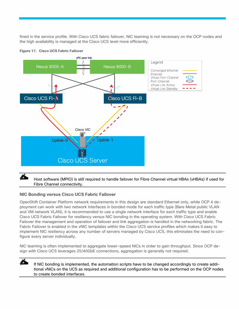
fined in the service profile. With Cisco UCS fabric failover, NIC teaming is not necessary on the OCP nodes and
the high availability is managed at the Cisco UCS level more efficiently.
Cisco UCS Fabric Failover Figure 17.
Host software (MPIO) is still required to handle failover for Fibre Channel virtual HBAs (vHBAs) if used for
Fibre Channel connectivity.
NIC Bonding versus Cisco UCS Fabric Failover
OpenShift Container Platform network requirements in this design are standard Ethernet only, while OCP 4 de-
ployment can work with two network interfaces in bonded mode for each traffic type (Bare Metal public VLAN
and VM network VLAN), it is recommended to use a single network interface for each traffic type and enable
Cisco UCS Fabric Failover for resiliency versus NIC bonding in the operating system. With Cisco UCS Fabric
Failover the management and operation of failover and link aggregation is handled in the networking fabric. The
Fabric Failover is enabled in the vNIC templates within the Cisco UCS service profiles which makes it easy to
implement NIC resiliency across any number of servers managed by Cisco UCS, this eliminates the need to con-
figure every server individually.
NIC teaming is often implemented to aggregate lower-speed NICs in order to gain throughput. Since OCP de-
sign with Cisco UCS leverages 25/40GbE connections, aggregation is generally not required.
If NIC bonding is implemented, the automation scripts have to be changed accordingly to create addi-
tional vNICs on the UCS as required and additional configuration has to be performed on the OCP nodes
to create bonded interfaces.
Service Profile Configuration
The Cisco UCS servers are stateless and are deployed using Cisco UCS Service Profiles (SP) that consists of
server identity information pulled from pools (WWPN, MAC, UUID, and so on) as well as policies covering con-
nectivity, firmware, and power control options, and so on. The service profiles are provisioned from the Cisco
UCS Service Profile Templates that allow rapid creation, as well as guaranteed consistency of the hosts at the
Cisco UCS hardware layer.
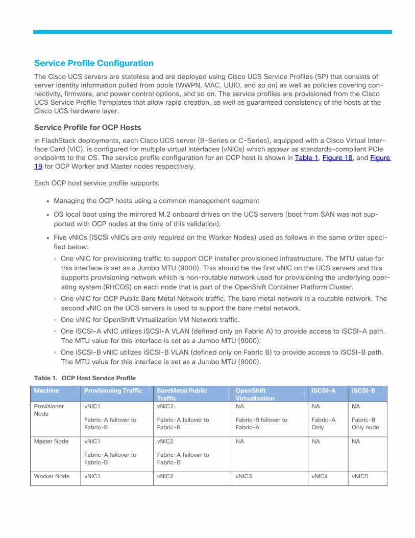
Service Profile for OCP Hosts
In FlashStack deployments, each Cisco UCS server (B-Series or C-Series), equipped with a Cisco Virtual Inter-
face Card (VIC), is configured for multiple virtual interfaces (vNICs) which appear as standards-compliant PCIe
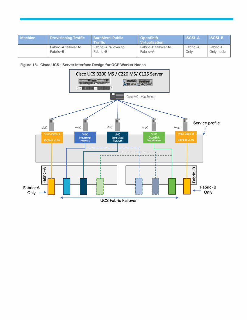
endpoints to the OS. The service profile configuration for an OCP host is shown in Table 1, Figure 18, and Figure
19 for OCP Worker and Master nodes respectively.
Each OCP host service profile supports:
● Managing the OCP hosts using a common management segment
● OS local boot using the mirrored M.2 onboard drives on the UCS servers (boot from SAN was not sup-
ported with OCP nodes at the time of this validation).
● Five vNICs (iSCSI vNICs are only required on the Worker Nodes) used as follows in the same order speci-
fied below:
◦ One vNIC for provisioning traffic to support OCP installer provisioned infrastructure. The MTU value for
this interface is set as a Jumbo MTU (9000). This should be the first vNIC on the UCS servers and this
supports provisioning network which is non-routable network used for provisioning the underlying oper-
ating system (RHCOS) on each node that is part of the OpenShift Container Platform Cluster.
◦ One vNIC for OCP Public Bare Metal Network traffic. The bare metal network is a routable network. The
second vNIC on the UCS servers is used to support the bare metal network.
◦ One vNIC for OpenShift Virtualization VM Network traffic.
◦ One iSCSI-A vNIC utilizes iSCSI-A VLAN (defined only on Fabric A) to provide access to iSCSI-A path.
The MTU value for this interface is set as a Jumbo MTU (9000).
◦ One iSCSI-B vNIC utilizes iSCSI-B VLAN (defined only on Fabric B) to provide access to iSCSI-B path.
The MTU value for this interface is set as a Jumbo MTU (9000).
Table 1. OCP Host Service Profile
Machine Provisioning Traffic BareMetal Public
Traffic
OpenShift
Virtualization
iSCSI-A iSCSI-B
Provisioner
Node
vNIC1
Fabric-A failover to
Fabric-B
vNIC2
Fabric-A failover to
Fabric-B
NA
Fabric-B failover to
Fabric-A
NA
Fabric-A
Only
NA
Fabric-B
Only node
Master Node vNIC1
Fabric-A failover to
Fabric-B
vNIC2
Fabric-A failover to
Fabric-B
NA
NA
NA
Worker Node vNIC1 vNIC2 vNIC3 vNIC4 vNIC5
Machine Provisioning Traffic BareMetal Public
Traffic
OpenShift
Virtualization
iSCSI-A iSCSI-B
Fabric-A failover to
Fabric-B
Fabric-A failover to
Fabric-B
Fabric-B failover to
Fabric-A
Fabric-A
Only
Fabric-B
Only node
Cisco UCS – Server Interface Design for OCP Worker Nodes Figure 18.
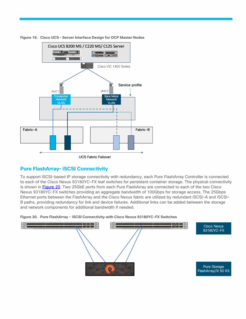
Cisco UCS – Server Interface Design for OCP Master Nodes Figure 19.
Pure FlashArray– iSCSI Connectivity
To support iSCSI-based IP storage connectivity with redundancy, each Pure FlashArray Controller is connected
to each of the Cisco Nexus 93180YC-FX leaf switches for persistent container storage. The physical connectivity
is shown in Figure 20. Two 25GbE ports from each Pure FlashArray are connected to each of the two Cisco
Nexus 93180YC-FX switches providing an aggregate bandwidth of 100Gbps for storage access. The 25Gbps
Ethernet ports between the FlashArray and the Cisco Nexus fabric are utilized by redundant iSCSI-A and iSCSI-
B paths, providing redundancy for link and device failures. Additional links can be added between the storage
and network components for additional bandwidth if needed.
Pure FlashArray - iSCSI Connectivity with Cisco Nexus 93180YC-FX Switches Figure 20.
FlashStack Storage Design for OCP
The FlashStack for OCP is based on Pure FlashArray storage system with Purity version 6.1.3. Pure CSI driver
(PSO) is an add-on component that needs to be installed on the OpenShift Container Platform cluster. PSO ena-
bles the integration between the storage and OCP cluster.
The block storage on the Pure FlashArray storage array support both fibre channel and iSCSI protocols. For the
purpose of this validated design, iSCSI was used for dynamic persistent storage for Containers and VMs.
Dynamic Storage Provisioning
OpenShift provides dynamic provisioning of storage for applications by utilizing the StorageClass resource. Us-
ing dynamic storage, you can select different types of back-end storage. The back-end storage is segregated
into different tiers depending on the needs of your application. When requesting storage, a user can specify a
PersistentVolumeClaim with an annotation that specifies the value of the StorageClass they prefer.
To order the storage, you must create a PVC. The PVC determines the specification for the storage that you
want to provision. After the PVC is created, the storage device and the PV are automatically created for you.
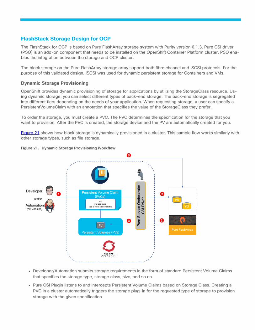
Figure 21 shows how block storage is dynamically provisioned in a cluster. This sample flow works similarly with
other storage types, such as file storage.
Dynamic Storage Provisioning Workflow Figure 21.
● Developer/Automation submits storage requirements in the form of standard Persistent Volume Claims
that specifies the storage type, storage class, size, and so on.
● Pure CSI Plugin listens to and intercepts Persistent Volume Claims based on Storage Class. Creating a
PVC in a cluster automatically triggers the storage plug-in for the requested type of storage to provision
storage with the given specification.
● Storage provisioning API call sent to Pure FlashArray and storage is provisioned.
● The storage plug-in automatically creates a persistent volume (PV) in the cluster, a virtual storage device
that points to the actual storage device on your Pure FlashArray.
● The PVC and PV are automatically connected to each other. The status of the PVC and the PV changes
to Bound and the PVC is used to mount persistent storage to your app. If you delete the PVC, the PV and
related storage instance are also deleted.
OCP Virtual Switching Architecture
The OpenShift Container Platform cluster uses a virtualized network for pod and service networks. The OVN-
Kubernetes Container Network Interface (CNI) plug-in is a network provider for the default cluster network. A
cluster that uses the OVN-Kubernetes network provider also runs Open vSwitch (OVS) on each node. OVN con-
figures OVS on each node to implement the declared network configuration.
The OVN-Kubernetes default Container Network Interface (CNI) network provider implements the following fea-
tures:
● Uses OVN (Open Virtual Network) to manage network traffic flows. OVN is a community developed, ven-
dor agnostic network virtualization solution.
● Implements Kubernetes network policy support, including ingress and egress rules.
● Uses the Geneve (Generic Network Virtualization Encapsulation) protocol rather than VXLAN to create an
overlay network between nodes.
Figure 22 shows the distribution of network interfaces on each OCP worker node with one Open vSwitch bridge,
for Pod-to-Pod communication and the other dedicated Linux bridge created for VM external network when
VMs are deployed leveraging OpenShift Virtualization feature. Each bridge has one NIC with in the OS providing
access to external networks. The other three network interfaces on the OCP nodes are used for communication
via provisioning network and access to iSCSI-A and iSCSI-B traffic via dedicated interfaces. Appropriate VLANs
are enabled at the Cisco UCS level to support different traffic types.
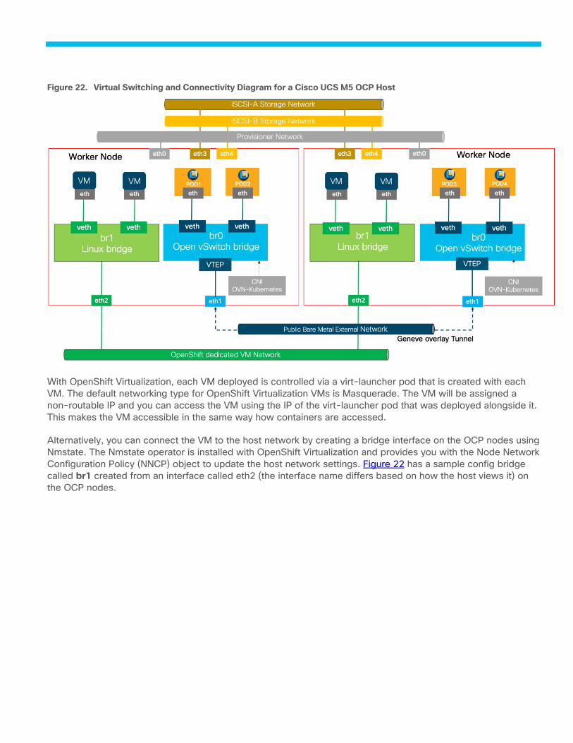
Virtual Switching and Connectivity Diagram for a Cisco UCS M5 OCP Host Figure 22.
With OpenShift Virtualization, each VM deployed is controlled via a virt-launcher pod that is created with each
VM. The default networking type for OpenShift Virtualization VMs is Masquerade. The VM will be assigned a
non-routable IP and you can access the VM using the IP of the virt-launcher pod that was deployed alongside it.
This makes the VM accessible in the same way how containers are accessed.
Alternatively, you can connect the VM to the host network by creating a bridge interface on the OCP nodes using
Nmstate. The Nmstate operator is installed with OpenShift Virtualization and provides you with the Node Network
Configuration Policy (NNCP) object to update the host network settings. Figure 22 has a sample config bridge
called br1 created from an interface called eth2 (the interface name differs based on how the host views it) on
the OCP nodes.
Solution Deployment
Deployment Hardware and Software
The deployment of hardware and software for FlashStack with OpenShift Container Platform is detailed in the
following sections.
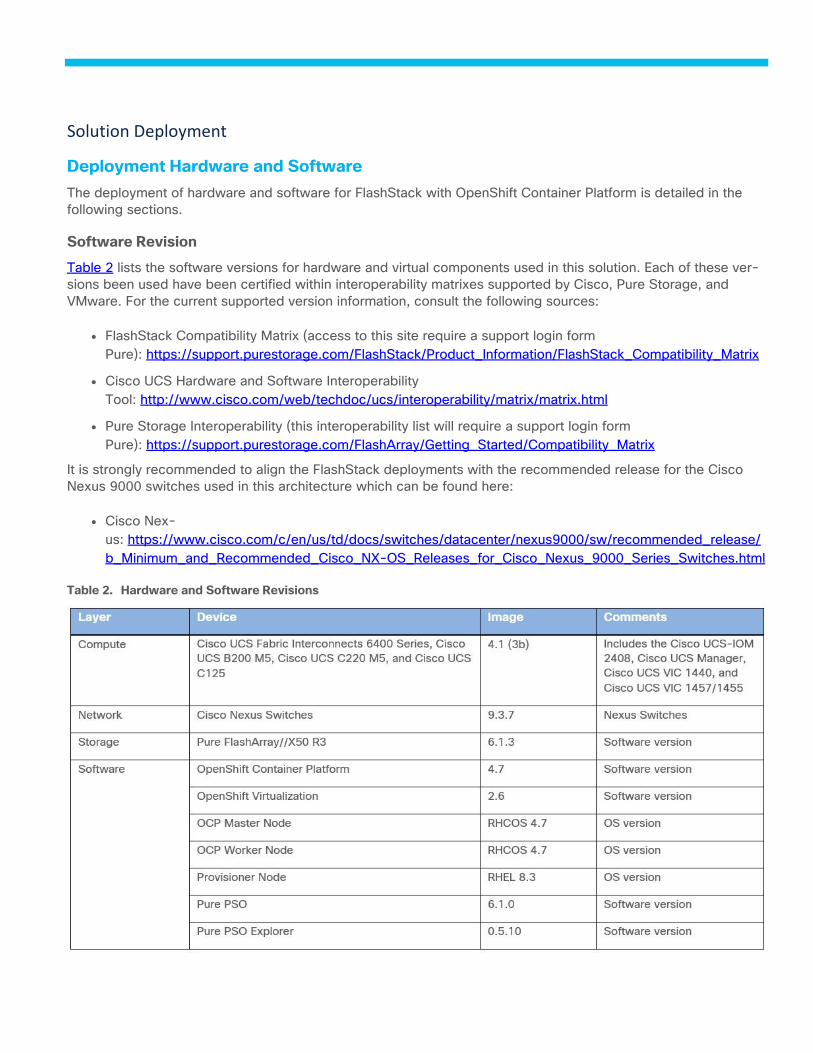
Software Revision
Table 2 lists the software versions for hardware and virtual components used in this solution. Each of these ver-
sions been used have been certified within interoperability matrixes supported by Cisco, Pure Storage, and
VMware. For the current supported version information, consult the following sources:
● FlashStack Compatibility Matrix (access to this site require a support login form
Pure): https://support.purestorage.com/FlashStack/Product_Information/FlashStack_Compatibility_Matrix
● Cisco UCS Hardware and Software Interoperability
Tool: http://www.cisco.com/web/techdoc/ucs/interoperability/matrix/matrix.html
● Pure Storage Interoperability (this interoperability list will require a support login form
Pure): https://support.purestorage.com/FlashArray/Getting_Started/Compatibility_Matrix
It is strongly recommended to align the FlashStack deployments with the recommended release for the Cisco
Nexus 9000 switches used in this architecture which can be found here:
● Cisco Nex-
us: https://www.cisco.com/c/en/us/td/docs/switches/datacenter/nexus9000/sw/recommended_release/
b_Minimum_and_Recommended_Cisco_NX-OS_Releases_for_Cisco_Nexus_9000_Series_Switches.html
Table 2. Hardware and Software Revisions

Physical Cabling for FlashStack with OCP Bare Metal
The information in this section is provided as a reference for cabling the physical equipment in a FlashStack en-
vironment. Customers can adjust the ports according to their individual setup but when done so the variables
have to be changed in the Ansible automation Playbooks. This document assumes that out-of-band manage-
ment ports are plugged into an existing management infrastructure at the deployment sites. The interfaces
shown in Figure 23 will be used in various configuration steps. Additional 1Gb management connections will be
needed for an out-of-band network switch that sits apart from the FlashStack infrastructure. Each Cisco UCS
fabric interconnect, Cisco Nexus switch and Pure FlashArray controller is connected to the out-of-band network
switch. Layer 3 network connectivity is required between the Out-of-Band (OOB) and In-Band (IB) Management
Subnets.
The deployment procedure in this document only explains the OCP cluster installation on Cisco UCS B-
Series for simplicity but has been also validated with the Cisco UCS C220 M5 server and the Cisco UCS
C125 server nodes. If you want to deploy the OCP cluster using Cisco UCS C-Series servers, please up-
date the automation scripts with the appropriate ports on the Cisco UCS 6454 FIs and change the BIOS
policy for the Cisco UCS C125 nodes if used. The interface names for the provisioning and bare metal
interfaces have to be also updated during the OCP installation; the required changes will be highlighted
when the appropriate sections are discussed in this document.
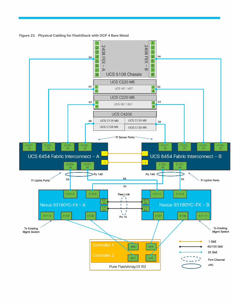
Physical Cabling for FlashStack with OCP 4 Bare Metal Figure 23.
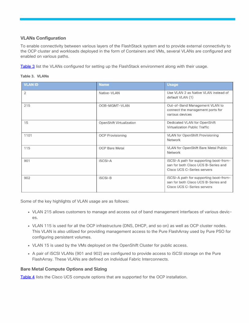
VLANs Configuration
To enable connectivity between various layers of the FlashStack system and to provide external connectivity to
the OCP cluster and workloads deployed in the form of Containers and VMs, several VLANs are configured and
enabled on various paths.
Table 3 list the VLANs configured for setting up the FlashStack environment along with their usage.
Table 3. VLANs
Some of the key highlights of VLAN usage are as follows:
● VLAN 215 allows customers to manage and access out of band management interfaces of various devic-
es.
● VLAN 115 is used for all the OCP infrastructure (DNS, DHCP, and so on) as well as OCP cluster nodes.
This VLAN is also utilized for providing management access to the Pure FlashArray used by Pure PSO for
configuring persistent volumes.
● VLAN 15 is used by the VMs deployed on the OpenShift Cluster for public access.
● A pair of iSCSI VLANs (901 and 902) are configured to provide access to iSCSI storage on the Pure
FlashArray. These VLANs are defined on individual Fabric Interconnects.
Bare Metal Compute Options and Sizing
Table 4 lists the Cisco UCS compute options that are supported for the OCP installation.
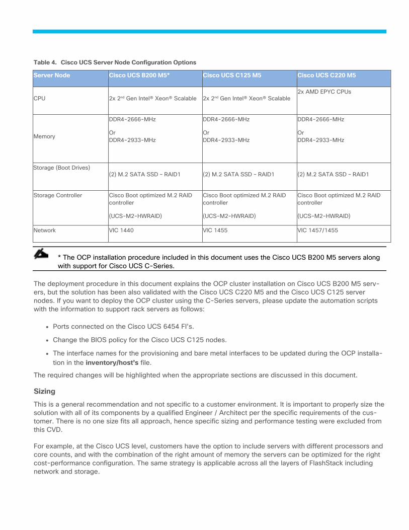
Table 4. Cisco UCS Server Node Configuration Options
Server Node Cisco UCS B200 M5* Cisco UCS C125 M5 Cisco UCS C220 M5
CPU 2x 2nd Gen Intel® Xeon® Scalable 2x 2nd Gen Intel® Xeon® Scalable 2x AMD EPYC CPUs
Memory
DDR4-2666-MHz
Or
DDR4-2933-MHz
DDR4-2666-MHz
Or
DDR4-2933-MHz
DDR4-2666-MHz
Or
DDR4-2933-MHz
Storage (Boot Drives)
(2) M.2 SATA SSD – RAID1 (2) M.2 SATA SSD – RAID1 (2) M.2 SATA SSD – RAID1
Storage Controller Cisco Boot optimized M.2 RAID
controller
(UCS-M2-HWRAID)
Cisco Boot optimized M.2 RAID
controller
(UCS-M2-HWRAID)
Cisco Boot optimized M.2 RAID
controller
(UCS-M2-HWRAID)
Network VIC 1440 VIC 1455 VIC 1457/1455
* The OCP installation procedure included in this document uses the Cisco UCS B200 M5 servers along
with support for Cisco UCS C-Series.
The deployment procedure in this document explains the OCP cluster installation on Cisco UCS B200 M5 serv-
ers, but the solution has been also validated with the Cisco UCS C220 M5 and the Cisco UCS C125 server
nodes. If you want to deploy the OCP cluster using the C-Series servers, please update the automation scripts
with the information to support rack servers as follows:
● Ports connected on the Cisco UCS 6454 FI’s.
● Change the BIOS policy for the Cisco UCS C125 nodes.
● The interface names for the provisioning and bare metal interfaces to be updated during the OCP installa-
tion in the inventory/host’s file.
The required changes will be highlighted when the appropriate sections are discussed in this document.
Sizing
This is a general recommendation and not specific to a customer environment. It is important to properly size the
solution with all of its components by a qualified Engineer / Architect per the specific requirements of the cus-
tomer. There is no one size fits all approach, hence specific sizing and performance testing were excluded from
this CVD.
For example, at the Cisco UCS level, customers have the option to include servers with different processors and
core counts, and with the combination of the right amount of memory the servers can be optimized for the right
cost-performance configuration. The same strategy is applicable across all the layers of FlashStack including
network and storage.

It is important to size the servers to meet the minimal requirements of the OCP platform, to account for failures
of servers and by that to make sure that OCP HA related rules can be followed upon server failure with enough
resources available for OCP to redistribute the workloads from the failing host or when performing upgrades and
other maintenance tasks.
Example Sizing Guidelines (Worker Nodes)
Determine how many nodes and pods are required for your OpenShift Container Platform cluster. Cluster scala-
bility correlates to the number of pods in a cluster environment. That number influences the other numbers in
your setup. See Cluster Limits for the latest limits for objects in OpenShift Container Platform.
Environment sizing can be done according to tested cluster maximums or according to your application require-
ments. While planning your environment, determine how many pods are expected to fit per node:
Required Pods per Cluster / Pods per Node = Total Number of Nodes Needed
If you want to scope your cluster at 2500 pods, assuming the 250 maximum pods per node, you will need at
least ten nodes:
2500 / 250 = 10
If you increase the number of nodes to 15, the pods per node distribution changes to 167 pods per node.
The current maximum number of pods per node is 250. However, the number of pods that fit on a node is de-
pendent on the application itself. Consider the application’s memory, CPU, and storage requirements.
Consider a sample application environment having the following components listed in Table 5.
Table 5. Sample Environment
Pod type Pod quantity Max memory CPU cores Persistent
storage
apache 100 500 MB 0.5 1 GB
node.js 200 1 GB 1 1 GB
postgresql 100 1 GB 2 10 GB
The overall resource requirements for this application are: 450 CPU cores, 350GB RAM, and 1.3TB stor-
age plus overhead required for OCP operations.
Ansible Automation Workflow and Solution Deployment
This FlashStack with OCP 4 Bare Metal solution uses a management workstation (control machine) to run Ansi-
ble playbooks to configure Cisco Nexus, Cisco UCS, Pure Storage and Install OCP Cluster.
Figure 24 illustrates the FlashStack with OCP 4 Bare Metal solution implementation workflow which is explained
in the following sections. The FlashStack infrastructure layers are first configured in the order illustrated in Figure
24 before installing the OCP on the Cisco UCS Bare Metal cluster.
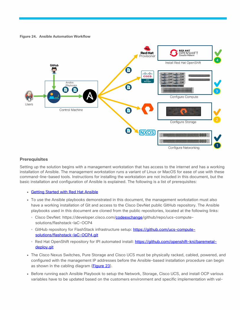
Ansible Automation Workflow Figure 24.
Prerequisites
Setting up the solution begins with a management workstation that has access to the internet and has a working
installation of Ansible. The management workstation runs a variant of Linux or MacOS for ease of use with these
command-line-based tools. Instructions for installing the workstation are not included in this document, but the
basic installation and configuration of Ansible is explained. The following is a list of prerequisites:
● Getting Started with Red Hat Ansible
● To use the Ansible playbooks demonstrated in this document, the management workstation must also
have a working installation of Git and access to the Cisco DevNet public GitHub repository. The Ansible
playbooks used in this document are cloned from the public repositories, located at the following links:
◦ Cisco DevNet: https://developer.cisco.com/codeexchange/github/repo/ucs-compute-
solutions/flashstack-IaC-OCP4
◦ GitHub repository for FlashStack infrastructure setup: https://github.com/ucs-compute-
solutions/flashstack-IaC-OCP4.git
◦ Red Hat OpenShift repository for IPI automated install: https://github.com/openshift-kni/baremetal-
deploy.git
● The Cisco Nexus Switches, Pure Storage and Cisco UCS must be physically racked, cabled, powered, and
configured with the management IP addresses before the Ansible-based installation procedure can begin
as shown in the cabling diagram (Figure 23).
● Before running each Ansible Playbook to setup the Network, Storage, Cisco UCS, and install OCP various
variables have to be updated based on the customers environment and specific implementation with val-
ues such as the VLANs, pools & ports on UCS, IP addresses for iSCSI interfaces and values needed for
the OCP installation.
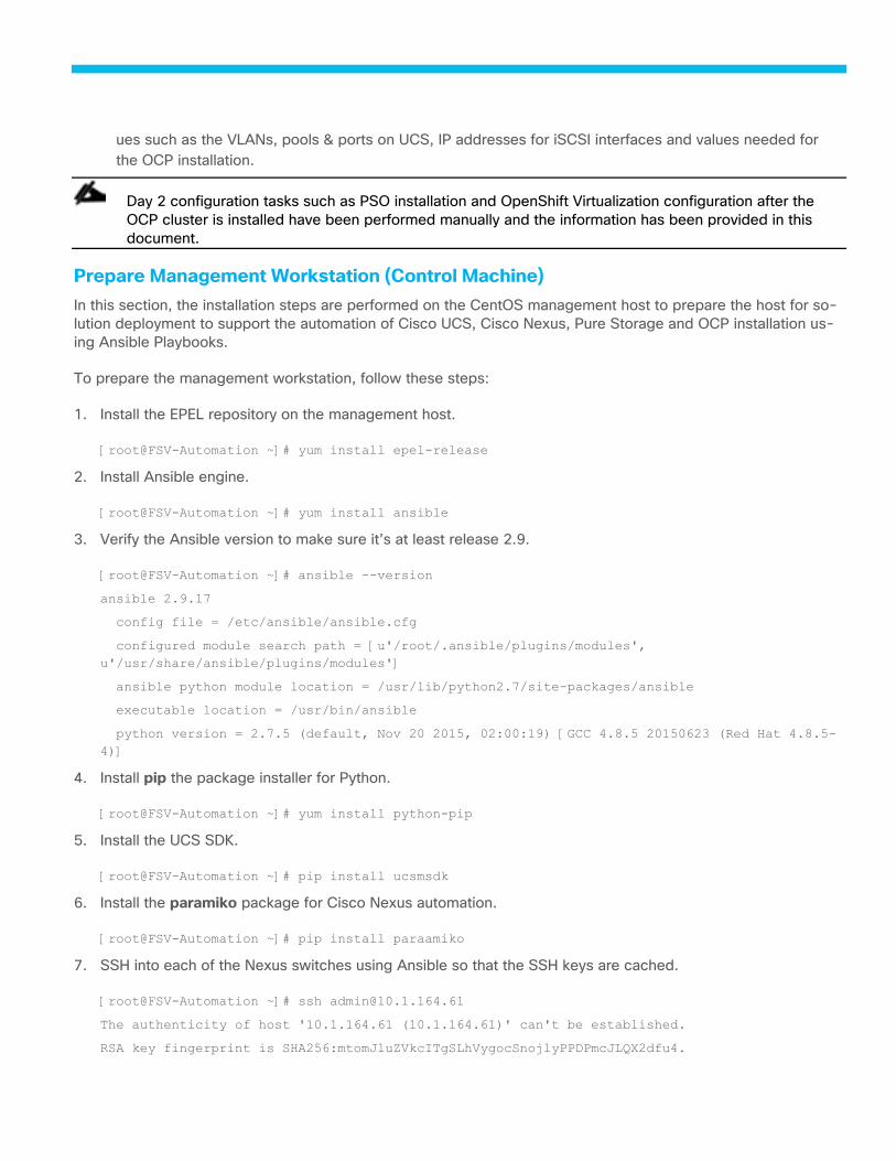
Day 2 configuration tasks such as PSO installation and OpenShift Virtualization configuration after the
OCP cluster is installed have been performed manually and the information has been provided in this
document.
Prepare Management Workstation (Control Machine)
In this section, the installation steps are performed on the CentOS management host to prepare the host for so-
lution deployment to support the automation of Cisco UCS, Cisco Nexus, Pure Storage and OCP installation us-
ing Ansible Playbooks.
To prepare the management workstation, follow these steps:
1. Install the EPEL repository on the management host.
[root@FSV-Automation ~]# yum install epel-release
2. Install Ansible engine.
[root@FSV-Automation ~]# yum install ansible
3. Verify the Ansible version to make sure it’s at least release 2.9.
[root@FSV-Automation ~]# ansible --version
ansible 2.9.17
config file = /etc/ansible/ansible.cfg
configured module search path = [u'/root/.ansible/plugins/modules',
u'/usr/share/ansible/plugins/modules']
ansible python module location = /usr/lib/python2.7/site-packages/ansible
executable location = /usr/bin/ansible
python version = 2.7.5 (default, Nov 20 2015, 02:00:19) [GCC 4.8.5 20150623 (Red Hat 4.8.5-
4)]
4. Install pip the package installer for Python.
[root@FSV-Automation ~]# yum install python-pip
5. Install the UCS SDK.
[root@FSV-Automation ~]# pip install ucsmsdk
6. Install the paramiko package for Cisco Nexus automation.
[root@FSV-Automation ~]# pip install paraamiko
7. SSH into each of the Nexus switches using Ansible so that the SSH keys are cached.
[root@FSV-Automation ~]# ssh [email protected]
The authenticity of host '10.1.164.61 (10.1.164.61)' can't be established.
RSA key fingerprint is SHA256:mtomJluZVkcITgSLhVygocSnojlyPPDPmcJLQX2dfu4.

RSA key fingerprint is MD5:b4:e3:86:97:99:58:df:0d:5d:20:b2:5b:d5:69:aa:23.
Are you sure you want to continue connecting (yes/no)? yes
Warning: Permanently added '10.1.164.61' (RSA) to the list of known hosts.
User Access Verification
Password:
8. Install the Pure Storage SDK.
[root@FSV-Automation ~]# pip install purestorage
9. Install ansible-galaxy collections for Cisco UCS, Cisco Nexus and Pure Storage Array as follows:
[root@FSV-Automation ~]# ansible-galaxy collection install cisco.nxos
[root@FSV-Automation ~]# ansible-galaxy collection install cisco.ucs
[root@FSV-Automation ~]# ansible-galaxy collection install purestorage.flasharray
10. Install the following python modules required for the OCP installation using Ansible.
● python-dns
● uri
[root@FSV-Automation ansible-ipi-install]# sudo yum install python-dns
[root@FSV-Automation ansible-ipi-install]# pip install uri
We validated the Ansible automation with both python 2.7.5 and python 3.6 as the python interpreter for
Ansible.
Clone GitHub Collection
You will use GitHub repos from two public locations; the first step in the process is to clone the GitHub collection
named flashstack-IaC-OCP4 (https://github.com/ucs-compute-solutions/flashstack-IaC-OCP4) and baremetal-
deploy (https://github.com/openshift-kni/baremetal-deploy) to the new empty folders on the management
workstation. Cloning the collections creates a local copy, which is then used to run the playbooks that have been
created for this solution. To clone the GitHub collection, follow these steps:
1. From the management workstation, create a new folder for the project. The GitHub collection will be cloned
in a new folder inside this one, named ocp4.
2. Open a command-line or console interface on the management workstation and change directories to the
new folder just created.
3. Clone the GitHub collection using the following command:
git clone https://github.com/ucs-compute-solutions/flashstack-IaC-OCP4.git
4. Change directories to the new folder named ocp4.
5. Change directories to the folder named Flashstack-IaC-OCP4.
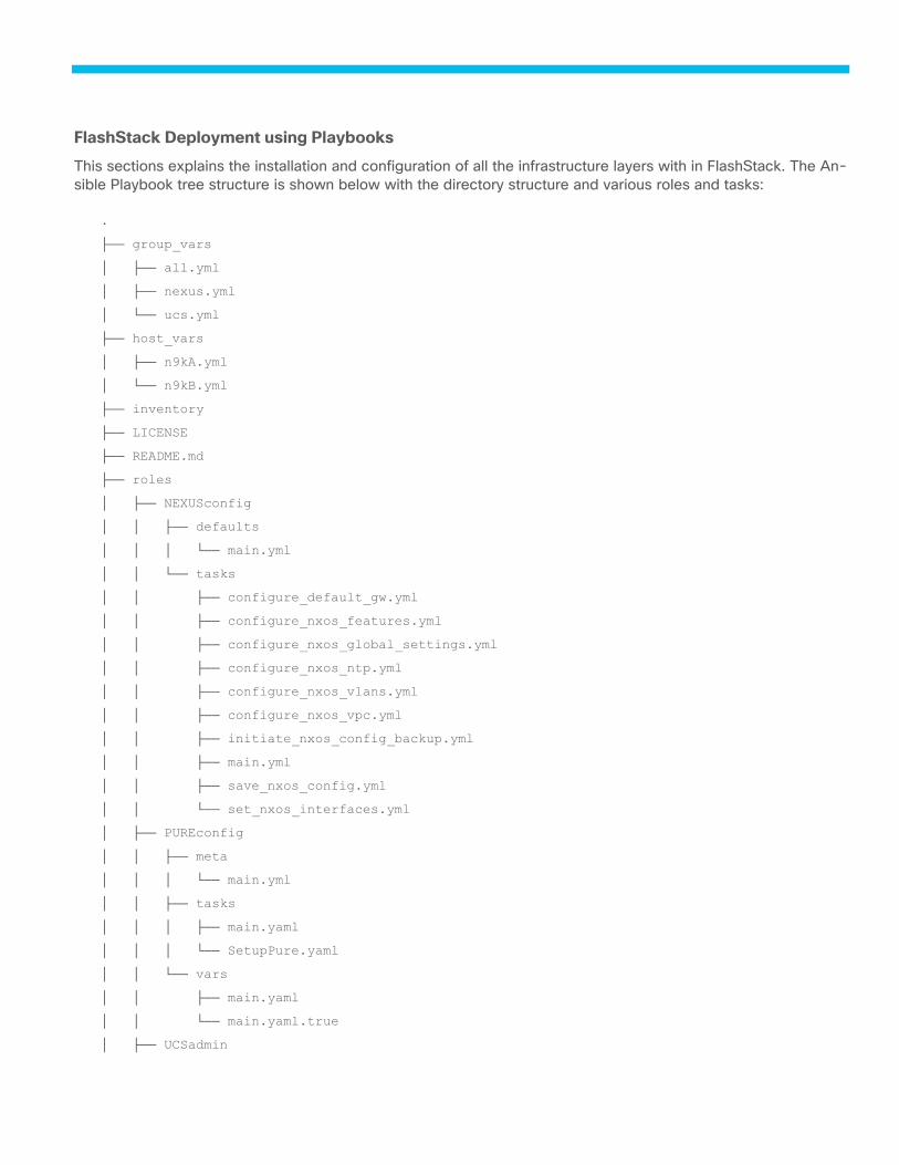
FlashStack Deployment using Playbooks
This sections explains the installation and configuration of all the infrastructure layers with in FlashStack. The An-
sible Playbook tree structure is shown below with the directory structure and various roles and tasks:
.
├── group_vars
│ ├── all.yml
│ ├── nexus.yml
│ └── ucs.yml
├── host_vars
│ ├── n9kA.yml
│ └── n9kB.yml
├── inventory
├── LICENSE
├── README.md
├── roles
│ ├── NEXUSconfig
│ │ ├── defaults
│ │ │ └── main.yml
│ │ └── tasks
│ │ ├── configure_default_gw.yml
│ │ ├── configure_nxos_features.yml
│ │ ├── configure_nxos_global_settings.yml
│ │ ├── configure_nxos_ntp.yml
│ │ ├── configure_nxos_vlans.yml
│ │ ├── configure_nxos_vpc.yml
│ │ ├── initiate_nxos_config_backup.yml
│ │ ├── main.yml
│ │ ├── save_nxos_config.yml
│ │ └── set_nxos_interfaces.yml
│ ├── PUREconfig
│ │ ├── meta
│ │ │ └── main.yml
│ │ ├── tasks
│ │ │ ├── main.yaml
│ │ │ └── SetupPure.yaml
│ │ └── vars
│ │ ├── main.yaml
│ │ └── main.yaml.true
│ ├── UCSadmin
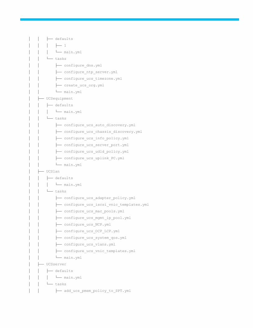
│ │ ├── defaults
│ │ │ ├── 1
│ │ │ └── main.yml
│ │ └── tasks
│ │ ├── configure_dns.yml
│ │ ├── configure_ntp_server.yml
│ │ ├── configure_ucs_timezone.yml
│ │ ├── create_ucs_org.yml
│ │ └── main.yml
│ ├── UCSequipment
│ │ ├── defaults
│ │ │ └── main.yml
│ │ └── tasks
│ │ ├── configure_ucs_auto_discovery.yml
│ │ ├── configure_ucs_chassis_discovery.yml
│ │ ├── configure_ucs_info_policy.yml
│ │ ├── configure_ucs_server_port.yml
│ │ ├── configure_ucs_udld_policy.yml
│ │ ├── configure_ucs_uplink_PC.yml
│ │ └── main.yml
│ ├── UCSlan
│ │ ├── defaults
│ │ │ └── main.yml
│ │ └── tasks
│ │ ├── configure_ucs_adapter_policy.yml
│ │ ├── configure_ucs_iscsi_vnic_templates.yml
│ │ ├── configure_ucs_mac_pools.yml
│ │ ├── configure_ucs_mgmt_ip_pool.yml
│ │ ├── configure_ucs_NCP.yml
│ │ ├── configure_ucs_OCP_LCP.yml
│ │ ├── configure_ucs_system_qos.yml
│ │ ├── configure_ucs_vlans.yml
│ │ ├── configure_ucs_vnic_templates.yml
│ │ └── main.yml
│ ├── UCSserver
│ │ ├── defaults
│ │ │ └── main.yml
│ │ └── tasks
│ │ ├── add_ucs_pmem_policy_to_SPT.yml
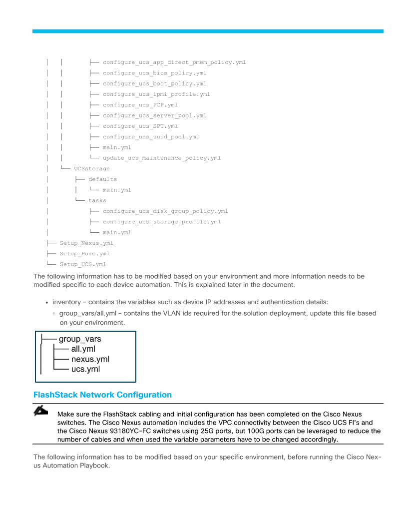
│ │ ├── configure_ucs_app_direct_pmem_policy.yml
│ │ ├── configure_ucs_bios_policy.yml
│ │ ├── configure_ucs_boot_policy.yml
│ │ ├── configure_ucs_ipmi_profile.yml
│ │ ├── configure_ucs_PCP.yml
│ │ ├── configure_ucs_server_pool.yml
│ │ ├── configure_ucs_SPT.yml
│ │ ├── configure_ucs_uuid_pool.yml
│ │ ├── main.yml
│ │ └── update_ucs_maintenance_policy.yml
│ └── UCSstorage
│ ├── defaults
│ │ └── main.yml
│ └── tasks
│ ├── configure_ucs_disk_group_policy.yml
│ ├── configure_ucs_storage_profile.yml
│ └── main.yml
├── Setup_Nexus.yml
├── Setup_Pure.yml
└── Setup_UCS.yml
The following information has to be modified based on your environment and more information needs to be
modified specific to each device automation. This is explained later in the document.
● inventory - contains the variables such as device IP addresses and authentication details:
◦ group_vars/all.yml – contains the VLAN ids required for the solution deployment, update this file based
on your environment.
FlashStack Network Configuration
Make sure the FlashStack cabling and initial configuration has been completed on the Cisco Nexus
switches. The Cisco Nexus automation includes the VPC connectivity between the Cisco UCS FI’s and
the Cisco Nexus 93180YC-FC switches using 25G ports, but 100G ports can be leveraged to reduce the
number of cables and when used the variable parameters have to be changed accordingly.
The following information has to be modified based on your specific environment, before running the Cisco Nex-
us Automation Playbook.
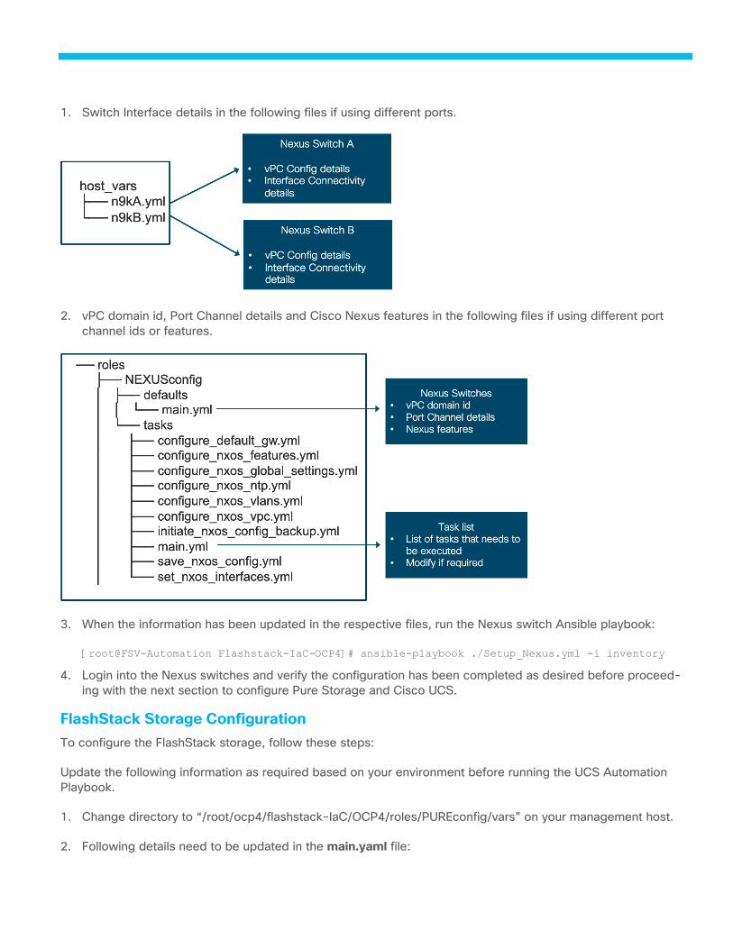
1. Switch Interface details in the following files if using different ports.
2. vPC domain id, Port Channel details and Cisco Nexus features in the following files if using different port
channel ids or features.
3. When the information has been updated in the respective files, run the Nexus switch Ansible playbook:
[root@FSV-Automation Flashstack-IaC-OCP4]# ansible-playbook ./Setup_Nexus.yml -i inventory
4. Login into the Nexus switches and verify the configuration has been completed as desired before proceed-
ing with the next section to configure Pure Storage and Cisco UCS.
FlashStack Storage Configuration
To configure the FlashStack storage, follow these steps:
Update the following information as required based on your environment before running the UCS Automation
Playbook.
1. Change directory to “/root/ocp4/flashstack-IaC/OCP4/roles/PUREconfig/vars” on your management host.
2. Following details need to be updated in the main.yaml file:
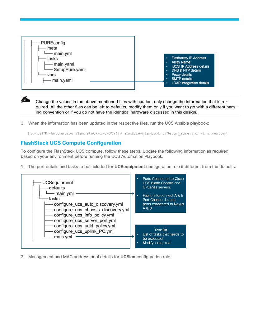
Change the values in the above mentioned files with caution, only change the information that is re-
quired. All the other files can be left to defaults, modify them only if you want to go with a different nam-
ing convention or if you do not have the identical hardware discussed in this design.
3. When the information has been updated in the respective files, run the UCS Ansible playbook:
[root@FSV-Automation Flashstack-IaC-OCP4]# ansible-playbook ./Setup_Pure.yml -i inventory
FlashStack UCS Compute Configuration
To configure the FlashStack UCS compute, follow these steps. Update the following information as required
based on your environment before running the UCS Automation Playbook.
1. The port details and tasks to be included for UCSequipment configuration role if different from the defaults.
2. Management and MAC address pool details for UCSlan configuration role.

3. UUID pool, UCS servers list and IPMI details for UCSServer configuration role.
Change the values in the mentioned files with caution; only change the information that is required. All
the other files can be left to defaults, modify them only if you want to go with a different naming conven-
tion or if you do not have the identical hardware discussed in this design.
Update “configure_ucs_bios_policy.yml” file if you are deploying OCP cluster on the Cisco UCS C125
servers to reflect the parameters required for AMD processors. Following document can be referred for
guidance https://www.cisco.com/c/en/us/products/collateral/servers-unified-computing/ucs-c-series-
rack-servers/performance-tuning-guide.html.
4. Once the information has been updated in the respective files, run the UCS Ansible playbook:
[root@FSV-Automation Flashstack-IaC-OCP4]# ansible-playbook ./Setup_UCS.yml -i inventory
5. Login into Cisco UCS Manager and verify the configuration has been completed as desired.
6. As part of the UCS Playbook, there are two Service Profile templates created, one for Master nodes and the
other for the worker nodes, we will use these service profile templates to create and assign Service Profiles
to the UCS servers. Either the master node or worker node service profile can be used for the provisioner
node.
Create UCS Service Profiles
To create service profiles from the service profile template, follow these steps:
1. Connect to the UCS 6454 Fabric Interconnect UCS Manager, click the Servers tab in the navigation pane.
2. Click Service Profile Templates > Sub-Organizations > OCP > Service Template OCP-Master.
3. Right-click OCP-Master and choose Create Service Profiles from Template.
4. Enter OCP-Master-0 for the service profile prefix.
5. Leave 1 as “Name Suffix Starting Number.”
6. Leave 3 for the “Number of Instances.”
7. Click OK to create the service profiles.
8. Click OK in the confirmation message to provision three FlashStack Service Profiles.
9. Click Service Profile Templates > Sub-Organizations > OCP > Service Template OCP-Worker.
10. Right-click OCP-Worker and choose Create Service Profiles from Template.
11. Enter OCP-Worker-0 for the service profile prefix.
12. Leave 1 as “Name Suffix Starting Number.”
13. Leave 2 for the “Number of Instances.”
14. Right-click OCP-Worker and choose Create Service Profiles from Template.
15. Enter Provisioner for the service profile prefix.
16. Leave 1 as “Name Suffix Starting Number.”
17. Leave 1 for the “Number of Instances.”
18. Click OK to create the service profiles.
19. Click OK in the confirmation message to provision three FlashStack Service Profiles
20. Wait for the Service Profile association to complete and proceed to the next steps details in the next section.
We will use one of the worker nodes service profile and use it as a provisioner node, the same can be
added as a worker node into the cluster later if desired without any changes, though a dedicated provi-
sioner node is recommended to simplify the expansion process that can be initiated from the provisioner
node. The validation team used a dedicated provisioner node and installed a cluster with two worker
nodes initially and expanded the cluster with one additional worker node.
OpenShift Container Platform Installation and Configuration
OCP 4.7 is deployed on the UCS infrastructure as Bare Metal servers. Three master nodes and two worker
nodes are deployed in the validation environment and additional worker nodes can easily be added to increase
the scalability of the solution. Figure 25. shows various OCP nodes used for deploying and managing a Red Hat
OCP cluster. This document will guide you through the process of using the Ansible playbooks to deploy a
Baremetal Installer Provisioned Infrastructure (IPI) of Red Hat OpenShift 4.7. For the manual deployment details
refer to Red Hat documentation at “https://docs.openshift.com/container-
platform/4.7/installing/installing_bare_metal_ipi/ipi-install-overview.html”.
OpenShift Container Platform – Installation Requirements
Installer-provisioned installation provides support for installing OpenShift Container Platform on bare metal
nodes. This guide provides a methodology to achieving a successful installation using Ansible.
During installer-provisioned installation on bare metal, the installer on the bare metal node labeled
as provisioner creates a bootstrap VM. The role of the bootstrap VM is to assist in the process of deploying an
OpenShift Container Platform cluster. The bootstrap VM connects to the baremetal network and to
the provisioning network, if present, via the network bridges. When the installation of OpenShift Container Plat-
form control plane nodes is complete and fully operational, the installer destroys the bootstrap VM automatically
and moves the virtual IP addresses (VIPs) to the appropriate nodes accordingly. The API VIP moves to the con-
trol plane nodes and the Ingress VIP moves to the worker nodes.
The installation of the OCP platform is a multi-step process that has to be carefully planned for each
customer environment. There are several prerequisites for preparing the infrastructure and the nodes for
the installation, and it is also important to recognize that the installation procedure may vary between the
different versions of OCP, the validation team tested installation of OCP 4.6 and 4.7 versions.
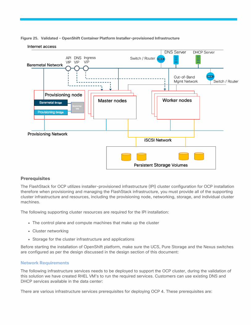
Validated - OpenShift Container Platform Installer-provisioned Infrastructure Figure 25.
Prerequisites
The FlashStack for OCP utilizes installer-provisioned infrastructure (IPI) cluster configuration for OCP installation
therefore when provisioning and managing the FlashStack infrastructure, you must provide all of the supporting
cluster infrastructure and resources, including the provisioning node, networking, storage, and individual cluster
machines.
The following supporting cluster resources are required for the IPI installation:
● The control plane and compute machines that make up the cluster
● Cluster networking
● Storage for the cluster infrastructure and applications
Before starting the installation of OpenShift platform, make sure the UCS, Pure Storage and the Nexus switches
are configured as per the design discussed in the design section of this document:
Network Requirements
The following infrastructure services needs to be deployed to support the OCP cluster, during the validation of
this solution we have created RHEL VM’s to run the required services. Customers can use existing DNS and
DHCP services available in the data center:
There are various infrastructure services prerequisites for deploying OCP 4. These prerequisites are:
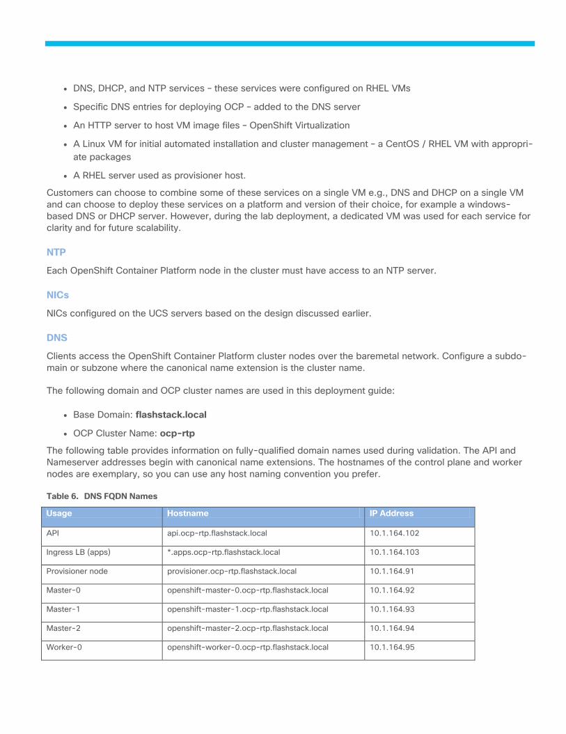
● DNS, DHCP, and NTP services – these services were configured on RHEL VMs
● Specific DNS entries for deploying OCP – added to the DNS server
● An HTTP server to host VM image files – OpenShift Virtualization
● A Linux VM for initial automated installation and cluster management – a CentOS / RHEL VM with appropri-
ate packages
● A RHEL server used as provisioner host.
Customers can choose to combine some of these services on a single VM e.g., DNS and DHCP on a single VM
and can choose to deploy these services on a platform and version of their choice, for example a windows-
based DNS or DHCP server. However, during the lab deployment, a dedicated VM was used for each service for
clarity and for future scalability.
NTP
Each OpenShift Container Platform node in the cluster must have access to an NTP server.
NICs
NICs configured on the UCS servers based on the design discussed earlier.
DNS
Clients access the OpenShift Container Platform cluster nodes over the baremetal network. Configure a subdo-
main or subzone where the canonical name extension is the cluster name.
The following domain and OCP cluster names are used in this deployment guide:
● Base Domain: flashstack.local
● OCP Cluster Name: ocp-rtp
The following table provides information on fully-qualified domain names used during validation. The API and
Nameserver addresses begin with canonical name extensions. The hostnames of the control plane and worker
nodes are exemplary, so you can use any host naming convention you prefer.
Table 6. DNS FQDN Names
Usage Hostname IP Address
API api.ocp-rtp.flashstack.local 10.1.164.102
Ingress LB (apps) *.apps.ocp-rtp.flashstack.local 10.1.164.103
Provisioner node provisioner.ocp-rtp.flashstack.local 10.1.164.91
Master-0 openshift-master-0.ocp-rtp.flashstack.local 10.1.164.92
Master-1 openshift-master-1.ocp-rtp.flashstack.local 10.1.164.93
Master-2 openshift-master-2.ocp-rtp.flashstack.local 10.1.164.94
Worker-0 openshift-worker-0.ocp-rtp.flashstack.local 10.1.164.95
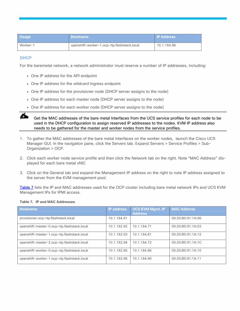
Usage Hostname IP Address
Worker-1 openshift-worker-1.ocp-rtp.flashstack.local 10.1.164.96
DHCP
For the baremetal network, a network administrator must reserve a number of IP addresses, including:
● One IP address for the API endpoint
● One IP address for the wildcard Ingress endpoint
● One IP address for the provisioner node (DHCP server assigns to the node)
● One IP address for each master node (DHCP server assigns to the node)
● One IP address for each worker node (DHCP server assigns to the node)
Get the MAC addresses of the bare metal Interfaces from the UCS service profiles for each node to be
used in the DHCP configuration to assign reserved IP addresses to the nodes. KVM IP address also
needs to be gathered for the master and worker nodes from the service profiles.
1. To gather the MAC addresses of the bare metal interfaces on the worker nodes, launch the Cisco UCS
Manager GUI. In the navigation pane, click the Servers tab. Expand Servers > Service Profiles > Sub-
Organization > OCP.
2. Click each worker node service profile and then click the Network tab on the right. Note “MAC Address” dis-
played for each bare metal vNIC
3. Click on the General tab and expand the Management IP address on the right to note IP address assigned to
the server from the KVM management pool.
Table 7 lists the IP and MAC addresses used for the OCP cluster including bare metal network IPs and UCS KVM
Management IPs for IPMI access.
Table 7. IP and MAC Addresses
Hostname IP address UCS KVM Mgmt. IP
Address
MAC Address
provisioner.ocp-rtp.flashstack.local 10.1.164.91 00:25:B5:91:1A:06
openshift-master-0.ocp-rtp.flashstack.local 10.1.162.92 10.1.164.71 00:25:B5:91:1A:03
openshift-master-1.ocp-rtp.flashstack.local 10.1.162.93 10.1.164.81 00:25:B5:91:1A:12
openshift-master-2.ocp-rtp.flashstack.local 10.1.162.94 10.1.164.72 00:25:B5:91:1A:1C
openshift-worker-0.ocp-rtp.flashstack.local 10.1.162.95 10.1.164.86 00:25:B5:91:1A:10
openshift-worker-1.ocp-rtp.flashstack.local 10.1.162.96 10.1.164.90 00:25:B5:91:1A:11
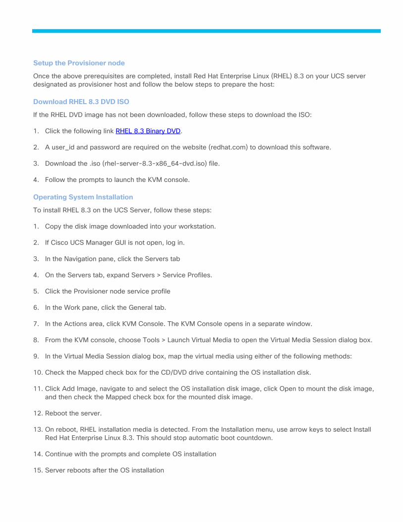
Setup the Provisioner node
Once the above prerequisites are completed, install Red Hat Enterprise Linux (RHEL) 8.3 on your UCS server
designated as provisioner host and follow the below steps to prepare the host:
Download RHEL 8.3 DVD ISO
If the RHEL DVD image has not been downloaded, follow these steps to download the ISO:
1. Click the following link RHEL 8.3 Binary DVD.
2. A user_id and password are required on the website (redhat.com) to download this software.
3. Download the .iso (rhel-server-8.3-x86_64-dvd.iso) file.
4. Follow the prompts to launch the KVM console.
Operating System Installation
To install RHEL 8.3 on the UCS Server, follow these steps:
1. Copy the disk image downloaded into your workstation.
2. If Cisco UCS Manager GUI is not open, log in.
3. In the Navigation pane, click the Servers tab
4. On the Servers tab, expand Servers > Service Profiles.
5. Click the Provisioner node service profile
6. In the Work pane, click the General tab.
7. In the Actions area, click KVM Console. The KVM Console opens in a separate window.
8. From the KVM console, choose Tools > Launch Virtual Media to open the Virtual Media Session dialog box.
9. In the Virtual Media Session dialog box, map the virtual media using either of the following methods:
10. Check the Mapped check box for the CD/DVD drive containing the OS installation disk.
11. Click Add Image, navigate to and select the OS installation disk image, click Open to mount the disk image,
and then check the Mapped check box for the mounted disk image.
12. Reboot the server.
13. On reboot, RHEL installation media is detected. From the Installation menu, use arrow keys to select Install
Red Hat Enterprise Linux 8.3. This should stop automatic boot countdown.
14. Continue with the prompts and complete OS installation
15. Server reboots after the OS installation
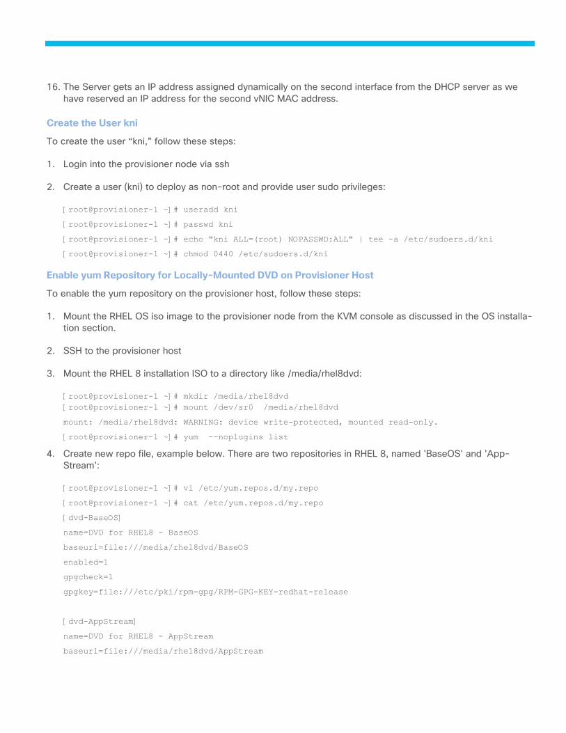
16. The Server gets an IP address assigned dynamically on the second interface from the DHCP server as we
have reserved an IP address for the second vNIC MAC address.
Create the User kni
To create the user “kni,” follow these steps:
1. Login into the provisioner node via ssh
2. Create a user (kni) to deploy as non-root and provide user sudo privileges:
[root@provisioner-1 ~]# useradd kni
[root@provisioner-1 ~]# passwd kni
[root@provisioner-1 ~]# echo "kni ALL=(root) NOPASSWD:ALL" | tee -a /etc/sudoers.d/kni
[root@provisioner-1 ~]# chmod 0440 /etc/sudoers.d/kni
Enable yum Repository for Locally-Mounted DVD on Provisioner Host
To enable the yum repository on the provisioner host, follow these steps:
1. Mount the RHEL OS iso image to the provisioner node from the KVM console as discussed in the OS installa-
tion section.
2. SSH to the provisioner host
3. Mount the RHEL 8 installation ISO to a directory like /media/rhel8dvd:
[root@provisioner-1 ~]# mkdir /media/rhel8dvd
[root@provisioner-1 ~]# mount /dev/sr0 /media/rhel8dvd
mount: /media/rhel8dvd: WARNING: device write-protected, mounted read-only.
[root@provisioner-1 ~]# yum --noplugins list
4. Create new repo file, example below. There are two repositories in RHEL 8, named 'BaseOS' and 'App-
Stream':
[root@provisioner-1 ~]# vi /etc/yum.repos.d/my.repo
[root@provisioner-1 ~]# cat /etc/yum.repos.d/my.repo
[dvd-BaseOS]
name=DVD for RHEL8 - BaseOS
baseurl=file:///media/rhel8dvd/BaseOS
enabled=1
gpgcheck=1
gpgkey=file:///etc/pki/rpm-gpg/RPM-GPG-KEY-redhat-release
[dvd-AppStream]
name=DVD for RHEL8 - AppStream
baseurl=file:///media/rhel8dvd/AppStream

enabled=1
gpgcheck=1
gpgkey=file:///etc/pki/rpm-gpg/RPM-GPG-KEY-redhat-release
5. Run the command yum clean all once:
[root@provisioner-1 ~]# yum clean all
[root@provisioner-1 ~]# yum --noplugins list
6. Check whether you can get the packages list from the DVD repositories.
[root@provisioner-1 ~]# yum --noplugins list
7. Manually install python3-crypto and python3-pyghmi packages on the provision host:
[root@provisioner-1 ~]# curl -o python3-crypto-2.6.1-18.el8ost.x86_64.rpm
https://trunk.rdoproject.org/rhel8-master/deps/latest/Packages/python3-crypto-2.6.1-
18.el8ost.x86_64.rpm
[root@provisioner-1 ~]# dnf -y install ./python3-crypto-2.6.1-18.el8ost.x86_64.rpm
[root@provisioner-1 ~]# curl -o python3-pyghmi-1.0.22-2.el8ost.noarch.rpm
https://trunk.rdoproject.org/rhel8-master/deps/latest/Packages/python3-pyghmi-1.0.22-
2.el8ost.noarch.rpm
[root@provisioner-1 ~]# dnf -y install ./python3-pyghmi-1.0.22-2.el8ost.noarch.rpm
Deploy IPI on Bare Metal using Ansible Playbook
The section provides detailed instructions to install OpenShift Container Platform 4.7 on UCS nodes using Ansi-
ble.
Run the Ansible Playbook to Install OCP Cluster
To run the Ansible Playbook, follow these steps:
1. Check whether you can get the packages list from the DVD repositories. The first step to using Ansible play-
book is to clone the baremetal-deploy repository.
2. Change directory to ocp4 and Clone the git repository:
[root@FS-Automation ocp4]# git clone https://github.com/openshift-kni/baremetal-deploy.git
Cloning into 'baremetal-deploy'...
remote: Enumerating objects: 33, done.
remote: Counting objects: 100% (33/33), done.
remote: Compressing objects: 100% (15/15), done.
remote: Total 6757 (delta 18), reused 33 (delta 18), pack-reused 6724
Receiving objects: 100% (6757/6757), 11.56 MiB | 0 bytes/s, done.
Resolving deltas: 100% (3546/3546), done.
The Ansible files tree structure is shown below:
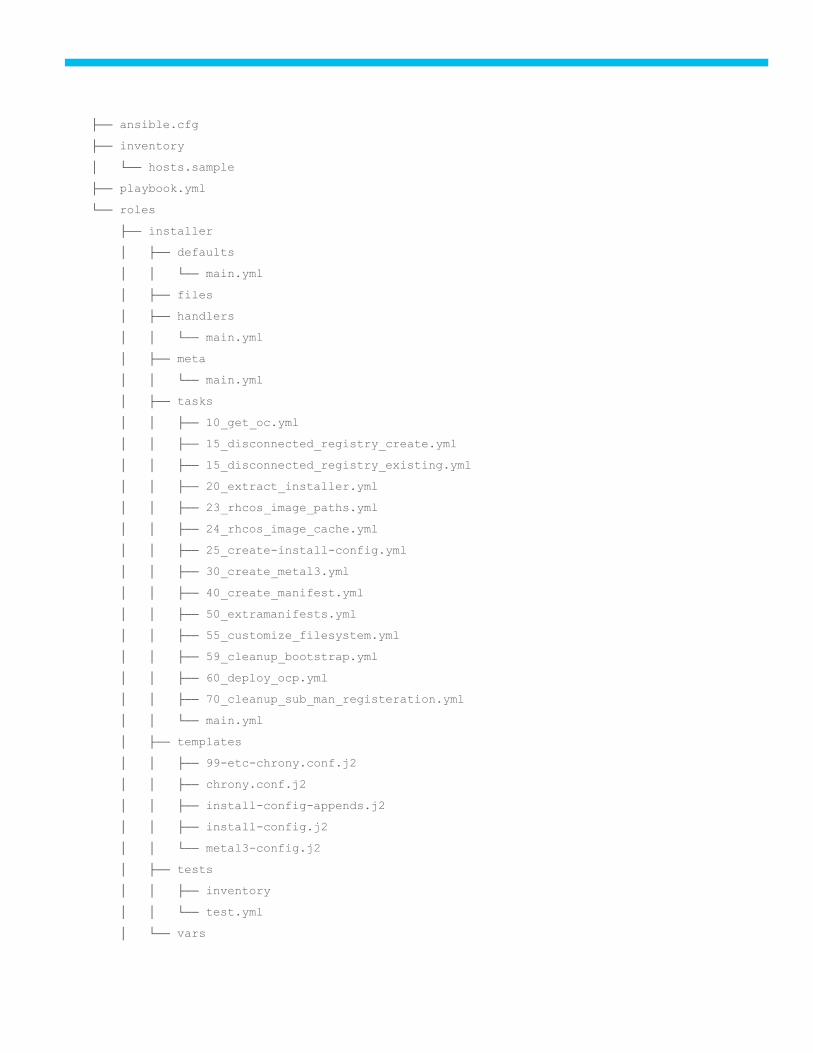
├── ansible.cfg
├── inventory
│ └── hosts.sample
├── playbook.yml
└── roles
├── installer
│ ├── defaults
│ │ └── main.yml
│ ├── files
│ ├── handlers
│ │ └── main.yml
│ ├── meta
│ │ └── main.yml
│ ├── tasks
│ │ ├── 10_get_oc.yml
│ │ ├── 15_disconnected_registry_create.yml
│ │ ├── 15_disconnected_registry_existing.yml
│ │ ├── 20_extract_installer.yml
│ │ ├── 23_rhcos_image_paths.yml
│ │ ├── 24_rhcos_image_cache.yml
│ │ ├── 25_create-install-config.yml
│ │ ├── 30_create_metal3.yml
│ │ ├── 40_create_manifest.yml
│ │ ├── 50_extramanifests.yml
│ │ ├── 55_customize_filesystem.yml
│ │ ├── 59_cleanup_bootstrap.yml
│ │ ├── 60_deploy_ocp.yml
│ │ ├── 70_cleanup_sub_man_registeration.yml
│ │ └── main.yml
│ ├── templates
│ │ ├── 99-etc-chrony.conf.j2
│ │ ├── chrony.conf.j2
│ │ ├── install-config-appends.j2
│ │ ├── install-config.j2
│ │ └── metal3-config.j2
│ ├── tests
│ │ ├── inventory
│ │ └── test.yml
│ └── vars
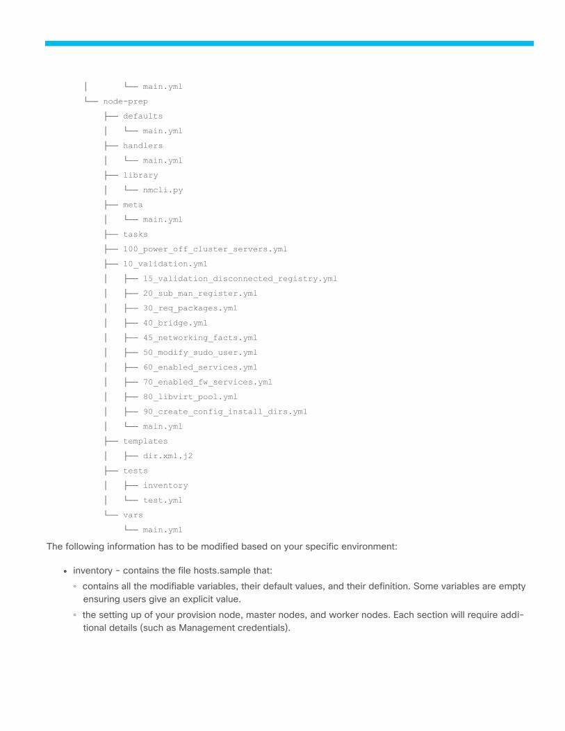
│ └── main.yml
└── node-prep
├── defaults
│ └── main.yml
├── handlers
│ └── main.yml
├── library
│ └── nmcli.py
├── meta
│ └── main.yml
├── tasks
├── 100_power_off_cluster_servers.yml
├── 10_validation.yml
│ ├── 15_validation_disconnected_registry.yml
│ ├── 20_sub_man_register.yml
│ ├── 30_req_packages.yml
│ ├── 40_bridge.yml
│ ├── 45_networking_facts.yml
│ ├── 50_modify_sudo_user.yml
│ ├── 60_enabled_services.yml
│ ├── 70_enabled_fw_services.yml
│ ├── 80_libvirt_pool.yml
│ ├── 90_create_config_install_dirs.yml
│ └── main.yml
├── templates
│ ├── dir.xml.j2
├── tests
│ ├── inventory
│ └── test.yml
└── vars
└── main.yml
The following information has to be modified based on your specific environment:
● inventory - contains the file hosts.sample that:
◦ contains all the modifiable variables, their default values, and their definition. Some variables are empty
ensuring users give an explicit value.
◦ the setting up of your provision node, master nodes, and worker nodes. Each section will require addi-
tional details (such as Management credentials).

● roles - contains two roles: node-prep and installer. node-prep handles all the prerequisites that the provi-
sioner node requires prior to running the installer. The installer role handles extracting the installer, setting
up the manifests, and running the Red Hat OpenShift installation.
3. Ensure that your environment is using Ansible 2.9 or greater. The following command can be used to verify:
[root@FSV-Automation ocp4]# ansible --version
4. Copy your public SSH key to your provisioner node using ssh-copy-id.
5. From the automation host, execute the following commands to copy the ssh key to provisioner host:
[root@FSV-Automation ocp4]# ssh-keygen
[root@FSV-Automation ocp4]# ssh-copy-id [email protected]
6. Modify the inventory/host’s file:
● The hosts file provides all the definable variables and provides a description of each variable. Some of the
variables are explicitly left empty and require user input for the playbook to run.
● The hosts file ensures all your nodes that will be used to deploy IPI on baremetal are setup. There are 4
groups: masters, workers, provisioner, and registry_host (optional). The masters and workers group col-
lects information about the host such as its name, role, user management (i.e., BMC) user, user manage-
ment (such as BMC) password, ipmi_address, ipmi_port to access the server and the provision mac ad-
dress (NIC1) that resides on the provisioning network.
● Below is a sample of the inventory/hosts file that has been used to install OCP cluster in the validation lab:
[root@FSV-Automation inventory]# cat hosts
[all:vars]
###############################################################################
# Required configuration variables for IPI on Baremetal Installations #
###############################################################################
# ansible_python_interpreter=/usr/bin/python3
# The provisioning NIC (NIC1) used on all baremetal nodes
prov_nic=ens5f0
# The public NIC (NIC2) used on all baremetal nodes
pub_nic=ens5f1
# (Optional) Set the provisioning bridge name. Default value is 'provisioning'.
#provisioning_bridge=provisioning
# (Optional) Set the baremetal bridge name. Default value is 'baremetal'.
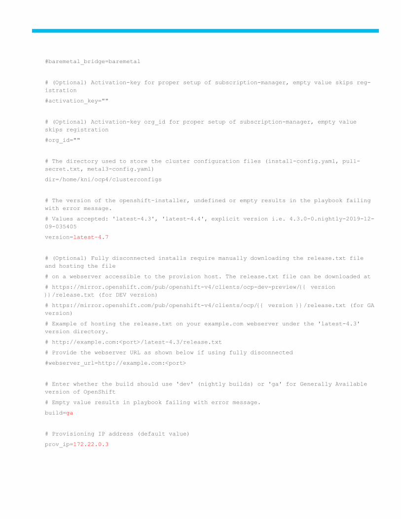
#baremetal_bridge=baremetal
# (Optional) Activation-key for proper setup of subscription-manager, empty value skips reg-
istration
#activation_key=""
# (Optional) Activation-key org_id for proper setup of subscription-manager, empty value
skips registration
#org_id=""
# The directory used to store the cluster configuration files (install-config.yaml, pull-
secret.txt, metal3-config.yaml)
dir=/home/kni/ocp4/clusterconfigs
# The version of the openshift-installer, undefined or empty results in the playbook failing
with error message.
# Values accepted: 'latest-4.3', 'latest-4.4', explicit version i.e. 4.3.0-0.nightly-2019-12-
09-035405
version=latest-4.7
# (Optional) Fully disconnected installs require manually downloading the release.txt file
and hosting the file
# on a webserver accessible to the provision host. The release.txt file can be downloaded at
# https://mirror.openshift.com/pub/openshift-v4/clients/ocp-dev-preview/{{ version
}}/release.txt (for DEV version)
# https://mirror.openshift.com/pub/openshift-v4/clients/ocp/{{ version }}/release.txt (for GA
version)
# Example of hosting the release.txt on your example.com webserver under the 'latest-4.3'
version directory.
# http://example.com:<port>/latest-4.3/release.txt
# Provide the webserver URL as shown below if using fully disconnected
#webserver_url=http://example.com:<port>
# Enter whether the build should use 'dev' (nightly builds) or 'ga' for Generally Available
version of OpenShift
# Empty value results in playbook failing with error message.
build=ga
# Provisioning IP address (default value)
prov_ip=172.22.0.3
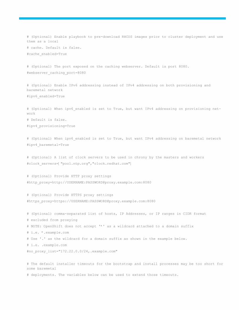
# (Optional) Enable playbook to pre-download RHCOS images prior to cluster deployment and use
them as a local
# cache. Default is false.
#cache_enabled=True
# (Optional) The port exposed on the caching webserver. Default is port 8080.
#webserver_caching_port=8080
# (Optional) Enable IPv6 addressing instead of IPv4 addressing on both provisioning and
baremetal network
#ipv6_enabled=True
# (Optional) When ipv6_enabled is set to True, but want IPv4 addressing on provisioning net-
work
# Default is false.
#ipv4_provisioning=True
# (Optional) When ipv6_enabled is set to True, but want IPv4 addressing on baremetal network
#ipv4_baremetal=True
# (Optional) A list of clock servers to be used in chrony by the masters and workers
#clock_servers=["pool.ntp.org","clock.redhat.com"]
# (Optional) Provide HTTP proxy settings
#http_proxy=http://USERNAME:[email protected]:8080
# (Optional) Provide HTTPS proxy settings
#https_proxy=https://USERNAME:[email protected]:8080
# (Optional) comma-separated list of hosts, IP Addresses, or IP ranges in CIDR format
# excluded from proxying
# NOTE: OpenShift does not accept '*' as a wildcard attached to a domain suffix
# i.e. *.example.com
# Use '.' as the wildcard for a domain suffix as shown in the example below.
# i.e. .example.com
#no_proxy_list="172.22.0.0/24,.example.com"
# The default installer timeouts for the bootstrap and install processes may be too short for
some baremetal
# deployments. The variables below can be used to extend those timeouts.
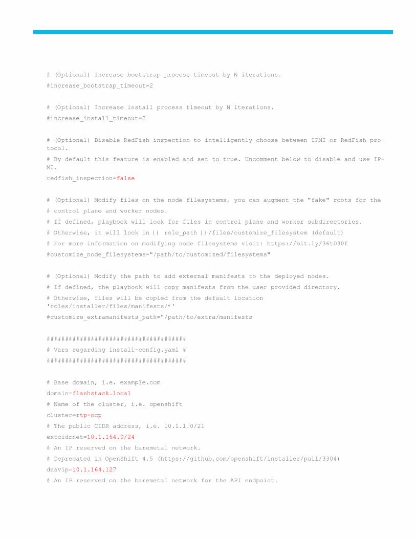
# (Optional) Increase bootstrap process timeout by N iterations.
#increase_bootstrap_timeout=2
# (Optional) Increase install process timeout by N iterations.
#increase_install_timeout=2
# (Optional) Disable RedFish inspection to intelligently choose between IPMI or RedFish pro-
tocol.
# By default this feature is enabled and set to true. Uncomment below to disable and use IP-
MI.
redfish_inspection=false
# (Optional) Modify files on the node filesystems, you can augment the "fake" roots for the
# control plane and worker nodes.
# If defined, playbook will look for files in control plane and worker subdirectories.
# Otherwise, it will look in {{ role_path }}/files/customize_filesystem (default)
# For more information on modifying node filesystems visit: https://bit.ly/36tD30f
#customize_node_filesystems="/path/to/customized/filesystems"
# (Optional) Modify the path to add external manifests to the deployed nodes.
# If defined, the playbook will copy manifests from the user provided directory.
# Otherwise, files will be copied from the default location
'roles/installer/files/manifests/*'
#customize_extramanifests_path="/path/to/extra/manifests
######################################
# Vars regarding install-config.yaml #
######################################
# Base domain, i.e. example.com
domain=flashstack.local
# Name of the cluster, i.e. openshift
cluster=rtp-ocp
# The public CIDR address, i.e. 10.1.1.0/21
extcidrnet=10.1.164.0/24
# An IP reserved on the baremetal network.
# Deprecated in OpenShift 4.5 (https://github.com/openshift/installer/pull/3304)
dnsvip=10.1.164.127
# An IP reserved on the baremetal network for the API endpoint.
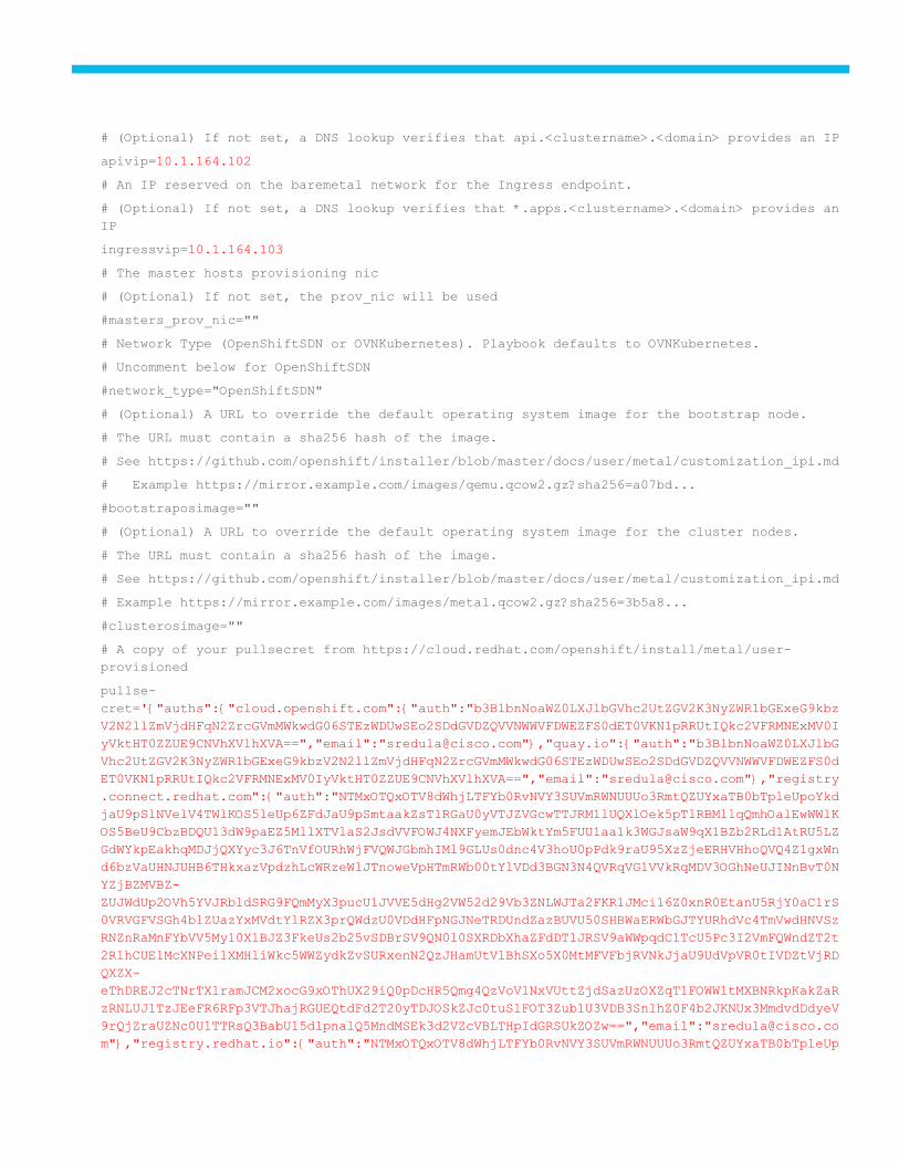
# (Optional) If not set, a DNS lookup verifies that api.<clustername>.<domain> provides an IP
apivip=10.1.164.102
# An IP reserved on the baremetal network for the Ingress endpoint.
# (Optional) If not set, a DNS lookup verifies that *.apps.<clustername>.<domain> provides an
IP
ingressvip=10.1.164.103
# The master hosts provisioning nic
# (Optional) If not set, the prov_nic will be used
#masters_prov_nic=""
# Network Type (OpenShiftSDN or OVNKubernetes). Playbook defaults to OVNKubernetes.
# Uncomment below for OpenShiftSDN
#network_type="OpenShiftSDN"
# (Optional) A URL to override the default operating system image for the bootstrap node.
# The URL must contain a sha256 hash of the image.
# See https://github.com/openshift/installer/blob/master/docs/user/metal/customization_ipi.md
# Example https://mirror.example.com/images/qemu.qcow2.gz?sha256=a07bd...
#bootstraposimage=""
# (Optional) A URL to override the default operating system image for the cluster nodes.
# The URL must contain a sha256 hash of the image.
# See https://github.com/openshift/installer/blob/master/docs/user/metal/customization_ipi.md
# Example https://mirror.example.com/images/metal.qcow2.gz?sha256=3b5a8...
#clusterosimage=""
# A copy of your pullsecret from https://cloud.redhat.com/openshift/install/metal/user-
provisioned
pullse-
cret='{"auths":{"cloud.openshift.com":{"auth":"b3BlbnNoaWZ0LXJlbGVhc2UtZGV2K3NyZWR1bGExeG9kbz
V2N2llZmVjdHFqN2ZrcGVmMWkwdG06STEzWDUwSEo2SDdGVDZQVVNWWVFDWEZFS0dET0VKN1pRRUtIQkc2VFRMNExMV0I
yVktHT0ZZUE9CNVhXVlhXVA==","email":"[email protected]"},"quay.io":{"auth":"b3BlbnNoaWZ0LXJlbG
Vhc2UtZGV2K3NyZWR1bGExeG9kbzV2N2llZmVjdHFqN2ZrcGVmMWkwdG06STEzWDUwSEo2SDdGVDZQVVNWWVFDWEZFS0d
ET0VKN1pRRUtIQkc2VFRMNExMV0IyVktHT0ZZUE9CNVhXVlhXVA==","email":"[email protected]"},"registry
.connect.redhat.com":{"auth":"NTMxOTQxOTV8dWhjLTFYb0RvNVY3SUVmRWNUUUo3RmtQZUYxaTB0bTpleUpoYkd
jaU9pSlNVelV4TWlKOS5leUp6ZFdJaU9pSmtaakZsT1RGaU0yVTJZVGcwTTJRM1lUQXlOek5pTlRBMllqQmhOalEwWWlK
OS5BeU9CbzBDQU13dW9paEZ5MllXTVlaS2JsdVVFOWJ4NXFyemJEbWktYm5FUU1aa1k3WGJsaW9qX1BZb2RLd1AtRU5LZ
GdWYkpEakhqMDJjQXYyc3J6TnVfOURhWjFVQWJGbmhIMl9GLUs0dnc4V3hoU0pPdk9raU95XzZjeERHVHhoQVQ4Z1gxWn
d6bzVaUHNJUHB6THkxazVpdzhLcWRzeWlJTnoweVpHTmRWb00tYlVDd3BGN3N4QVRqVG1VVkRqMDV3OGhNeUJINnBvT0N
YZjBZMVBZ-
ZUJWdUp2OVh5YVJRbldSRG9FQmMyX3pucU1JVVE5dHg2VW52d29Vb3ZNLWJTa2FKR1JMci16Z0xnR0EtanU5RjY0aC1rS
0VRVGFVSGh4blZUazYxMVdtYlRZX3prQWdzU0VDdHFpNGJNeTRDUndZazBUVU50SHBWaERWbGJTYURhdVc4TmVwdHNVSz
RNZnRaMnFYbVV5My10X1BJZ3FkeUs2b25vSDBrSV9QN0l0SXRDbXhaZFdDTlJRSV9aWWpqdC1TcU5Pc3I2VmFQWndZT2t
2R1hCUE1McXNPei1XMHliWkc5WWZydkZvSURxenN2QzJHamUtVlBhSXo5X0MtMFVFbjRVNkJjaU9UdVpVR0tIVDZtVjRD
QXZX-
eThDREJ2cTNrTXlramJCM2xocG9xOThUX29iQ0pDcHR5Qmg4QzVoV1NxVUttZjdSazUzOXZqT1FOWWltMXBNRkpKakZaR
zRNLUJ1TzJEeFR6RFp3VTJhajRGUEQtdFd2T20yTDJOSkZJc0tuSlFOT3Zub1U3VDB3SnlhZ0F4b2JKNUx3MmdvdDdyeV
9rQjZraUZNc0U1TTRsQ3BabU15dlpnalQ5MndMSEk3d2VZcVBLTHpIdGRSUkZOZw==","email":"[email protected]
m"},"registry.redhat.io":{"auth":"NTMxOTQxOTV8dWhjLTFYb0RvNVY3SUVmRWNUUUo3RmtQZUYxaTB0bTpleUp
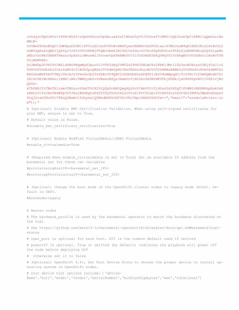
oYkdjaU9pSlNVelV4TWlKOS5leUp6ZFdJaU9pSmtaakZsT1RGaU0yVTJZVGcwTTJRM1lUQXlOek5pTlRBMllqQmhOalEw
WWlK-
OS5BeU9CbzBDQU13dW9paEZ5MllXTVlaS2JsdVVFOWJ4NXFyemJEbWktYm5FUU1aa1k3WGJsaW9qX1BZb2RLd1AtRU5LZ
GdWYkpEakhqMDJjQXYyc3J6TnVfOURhWjFVQWJGbmhIMl9GLUs0dnc4V3hoU0pPdk9raU95XzZjeERHVHhoQVQ4Z1gxWn
d6bzVaUHNJUHB6THkxazVpdzhLcWRzeWlJTnoweVpHTmRWb00tYlVDd3BGN3N4QVRqVG1VVkRqMDV3OGhNeUJINnBvT0N
YZjBZMVBZ-
ZUJWdUp2OVh5YVJRbldSRG9FQmMyX3pucU1JVVE5dHg2VW52d29Vb3ZNLWJTa2FKR1JMci16Z0xnR0EtanU5RjY0aC1rS
0VRVGFVSGh4blZUazYxMVdtYlRZX3prQWdzU0VDdHFpNGJNeTRDUndZazBUVU50SHBWaERWbGJTYURhdVc4TmVwdHNVSz
RNZnRaMnFYbVV5My10X1BJZ3FkeUs2b25vSDBrSV9QN0l0SXRDbXhaZFdDTlJRSV9aWWpqdC1TcU5Pc3I2VmFQWndZT2t
2R1hCUE1McXNPei1XMHliWkc5WWZydkZvSURxenN2QzJHamUtVlBhSXo5X0MtMFVFbjRVNkJjaU9UdVpVR0tIVDZtVjRD
QXZX-
eThDREJ2cTNrTXlramJCM2xocG9xOThUX29iQ0pDcHR5Qmg4QzVoV1NxVUttZjdSazUzOXZqT1FOWWltMXBNRkpKakZaR
zRNLUJ1TzJEeFR6RFp3VTJhajRGUEQtdFd2T20yTDJOSkZJc0tuSlFOT3Zub1U3VDB3SnlhZ0F4b2JKNUx3MmdvdDdyeV
9rQjZraUZNc0U1TTRsQ3BabU15dlpnalQ5MndMSEk3d2VZcVBLTHpIdGRSUkZOZw==","email":"[email protected]
m"}}}'
# (Optional) Disable BMC Certification Validation. When using self-signed certificates for
your BMC, ensure to set to True.
# Default value is False.
#disable_bmc_certificate_verification=True
# (Optional) Enable RedFish VirtualMedia/iDRAC VirtualMedia
#enable_virtualmedia=True
# (Required when enable_virtualmedia is set to True) Set an available IP address from the
baremetal net for these two variables
#provisioningHostIP=<baremetal_net_IP1>
#bootstrapProvisioningIP=<baremetal_net_IP2>
# (Optional) Change the boot mode of the OpenShift cluster nodes to legacy mode (BIOS). De-
fault is UEFI.
#bootmode=legacy
# Master nodes
# The hardware_profile is used by the baremetal operator to match the hardware discovered on
the host
# See https://github.com/metal3-io/baremetal-operator/blob/master/docs/api.md#baremetalhost-
status
# ipmi_port is optional for each host. 623 is the common default used if omitted
# poweroff is optional. True or omitted (by default) indicates the playbook will power off
the node before deploying OCP
# otherwise set it to false
# (Optional) OpenShift 4.6+, Set Root Device Hints to choose the proper device to install op-
erating system on OpenShift nodes.
# root device hint options include: ['device-
Name','hctl','model','vendor','serialNumber','minSizeGigabytes','wwn','rotational']
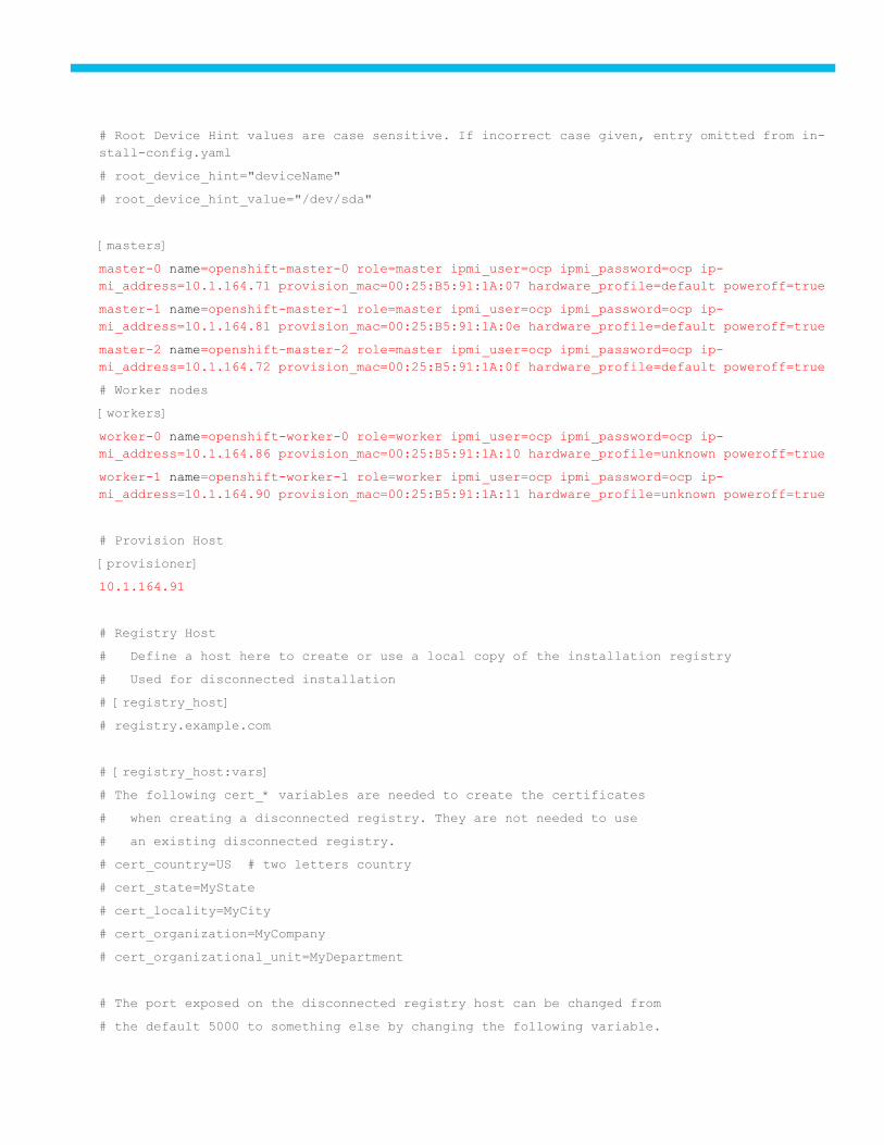
# Root Device Hint values are case sensitive. If incorrect case given, entry omitted from in-
stall-config.yaml
# root_device_hint="deviceName"
# root_device_hint_value="/dev/sda"
[masters]
master-0 name=openshift-master-0 role=master ipmi_user=ocp ipmi_password=ocp ip-
mi_address=10.1.164.71 provision_mac=00:25:B5:91:1A:07 hardware_profile=default poweroff=true
master-1 name=openshift-master-1 role=master ipmi_user=ocp ipmi_password=ocp ip-
mi_address=10.1.164.81 provision_mac=00:25:B5:91:1A:0e hardware_profile=default poweroff=true
master-2 name=openshift-master-2 role=master ipmi_user=ocp ipmi_password=ocp ip-
mi_address=10.1.164.72 provision_mac=00:25:B5:91:1A:0f hardware_profile=default poweroff=true
# Worker nodes
[workers]
worker-0 name=openshift-worker-0 role=worker ipmi_user=ocp ipmi_password=ocp ip-
mi_address=10.1.164.86 provision_mac=00:25:B5:91:1A:10 hardware_profile=unknown poweroff=true
worker-1 name=openshift-worker-1 role=worker ipmi_user=ocp ipmi_password=ocp ip-
mi_address=10.1.164.90 provision_mac=00:25:B5:91:1A:11 hardware_profile=unknown poweroff=true
# Provision Host
[provisioner]
10.1.164.91
# Registry Host
# Define a host here to create or use a local copy of the installation registry
# Used for disconnected installation
# [registry_host]
# registry.example.com
# [registry_host:vars]
# The following cert_* variables are needed to create the certificates
# when creating a disconnected registry. They are not needed to use
# an existing disconnected registry.
# cert_country=US # two letters country
# cert_state=MyState
# cert_locality=MyCity
# cert_organization=MyCompany
# cert_organizational_unit=MyDepartment
# The port exposed on the disconnected registry host can be changed from
# the default 5000 to something else by changing the following variable.
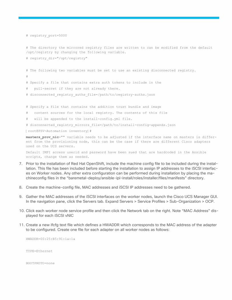
# registry_port=5000
# The directory the mirrored registry files are written to can be modified from the default
/opt/registry by changing the following variable.
# registry_dir="/opt/registry"
# The following two variables must be set to use an existing disconnected registry.
#
# Specify a file that contains extra auth tokens to include in the
# pull-secret if they are not already there.
# disconnected_registry_auths_file=/path/to/registry-auths.json
# Specify a file that contains the addition trust bundle and image
# content sources for the local registry. The contents of this file
# will be appended to the install-config.yml file.
# disconnected_registry_mirrors_file=/path/to/install-config-appends.json
[root@FSV-Automation inventory]#
masters_prov_nic="" variable needs to be adjusted if the interface name on masters is differ-
ent from the provisioning node, this can be the case if there are different Cisco adapters
used on the UCS servers.
Default IMPI access userid and password have been sued that are hardcoded in the Ansible
scripts, change them as needed.
7. Prior to the installation of Red Hat OpenShift, include the machine config file to be included during the instal-
lation. This file has been included before starting the installation to assign IP addresses to the iSCSI interfac-
es on Worker nodes. Any other extra configuration can be performed during installation by placing the ma-
chineconfig files in the “baremetal-deploy/ansible-ipi-install/roles/installer/files/manifests” directory.
8. Create the machine-config file, MAC addresses and iSCSI IP addresses need to be gathered.
9. Gather the MAC addresses of the iSCSI interfaces on the worker nodes, launch the Cisco UCS Manager GUI.
In the navigation pane, click the Servers tab. Expand Servers > Service Profiles > Sub-Organization > OCP.
10. Click each worker node service profile and then click the Network tab on the right. Note “MAC Address” dis-
played for each iSCSI vNIC
11. Create a new ifcfg text file which defines a HWADDR which corresponds to the MAC address of the adapter
to be configured. Create one file for each adapter on all worker nodes as follows:
HWADDR=00:25:B5:91:1a:1a
TYPE=Ethernet
BOOTPROTO=none
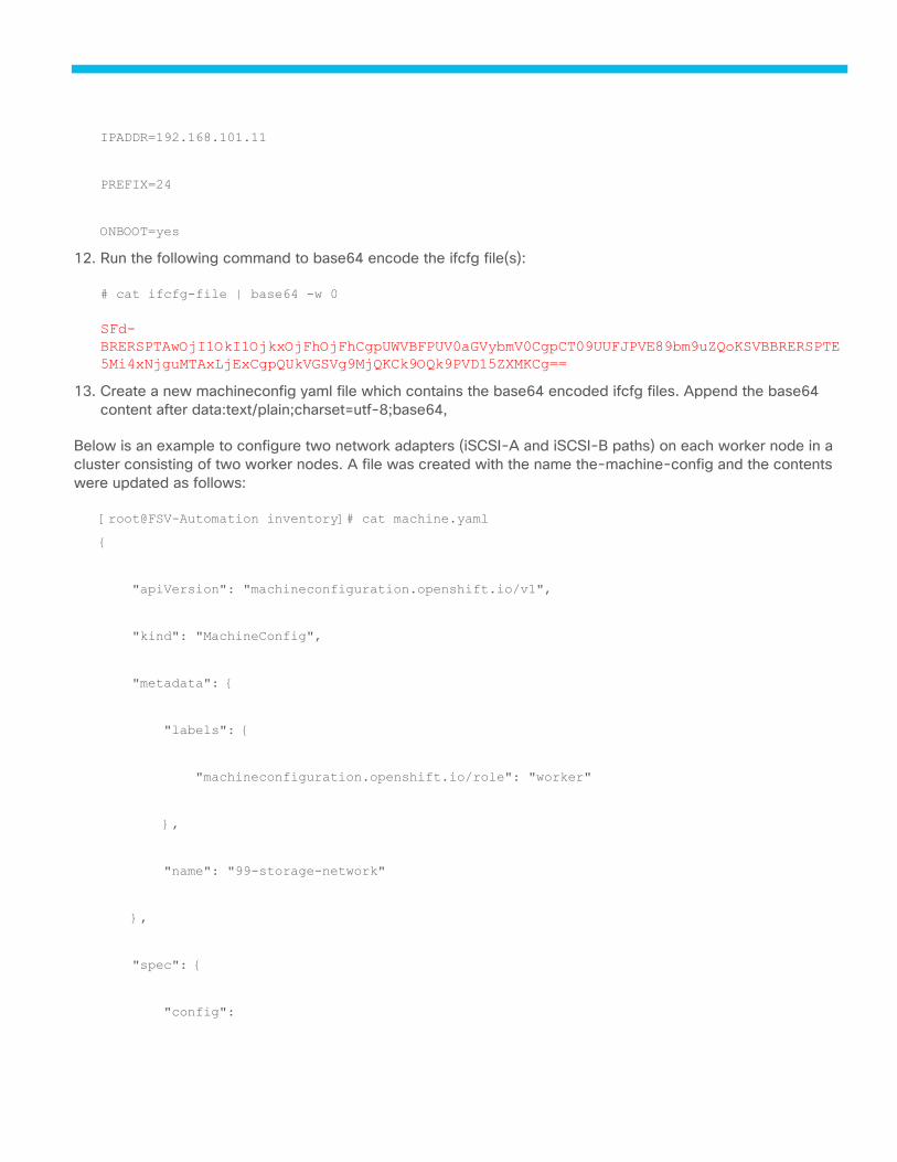
IPADDR=192.168.101.11
PREFIX=24
ONBOOT=yes
12. Run the following command to base64 encode the ifcfg file(s):
# cat ifcfg-file | base64 -w 0
SFd-
BRERSPTAwOjI1OkI1OjkxOjFhOjFhCgpUWVBFPUV0aGVybmV0CgpCT09UUFJPVE89bm9uZQoKSVBBRERSPTE
5Mi4xNjguMTAxLjExCgpQUkVGSVg9MjQKCk9OQk9PVD15ZXMKCg==
13. Create a new machineconfig yaml file which contains the base64 encoded ifcfg files. Append the base64
content after data:text/plain;charset=utf-8;base64,
Below is an example to configure two network adapters (iSCSI-A and iSCSI-B paths) on each worker node in a
cluster consisting of two worker nodes. A file was created with the name the-machine-config and the contents
were updated as follows:
[root@FSV-Automation inventory]# cat machine.yaml
{
"apiVersion": "machineconfiguration.openshift.io/v1",
"kind": "MachineConfig",
"metadata": {
"labels": {
"machineconfiguration.openshift.io/role": "worker"
},
"name": "99-storage-network"
},
"spec": {
"config":
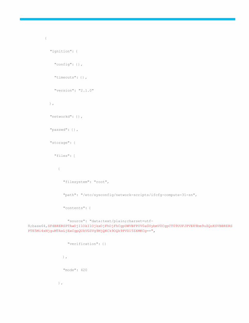
{
"ignition": {
"config": {},
"timeouts": {},
"version": "2.1.0"
},
"networkd": {},
"passwd": {},
"storage": {
"files": [
{
"filesystem": "root",
"path": "/etc/sysconfig/network-scripts/ifcfg-compute-31-sn",
"contents": {
"source": "data:text/plain;charset=utf-
8;base64,SFdBRERSPTAwOjI1OkI1OjkxOjFhOjFhCgpUWVBFPUV0aGVybmV0CgpCT09UUFJPVE89bm9uZQoKSVBBRERS
PTE5Mi4xNjguMTAxLjExCgpQUkVGSVg9MjQKCk9OQk9PVD15ZXMKCg==",
"verification": {}
},
"mode": 420
},
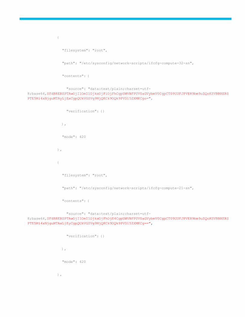
{
"filesystem": "root",
"path": "/etc/sysconfig/network-scripts/ifcfg-compute-32-sn",
"contents": {
"source": "data:text/plain;charset=utf-
8;base64,SFdBRERSPTAwOjI1OmI1OjkxOjFiOjFhCgpUWVBFPUV0aGVybmV0CgpCT09UUFJPVE89bm9uZQoKSVBBRERS
PTE5Mi4xNjguMTAyLjExCgpQUkVGSVg9MjQKCk9OQk9PVD15ZXMKCgo=",
"verification": {}
},
"mode": 420
},
{
"filesystem": "root",
"path": "/etc/sysconfig/network-scripts/ifcfg-compute-21-sn",
"contents": {
"source": "data:text/plain;charset=utf-
8;base64,SFdBRERSPTAwOjI1OmI1OjkxOjFhOjE4CgpUWVBFPUV0aGVybmV0CgpCT09UUFJPVE89bm9uZQoKSVBBRERS
PTE5Mi4xNjguMTAxLjEyCgpQUkVGSVg9MjQKCk9OQk9PVD15ZXMKCg==",
"verification": {}
},
"mode": 420
},
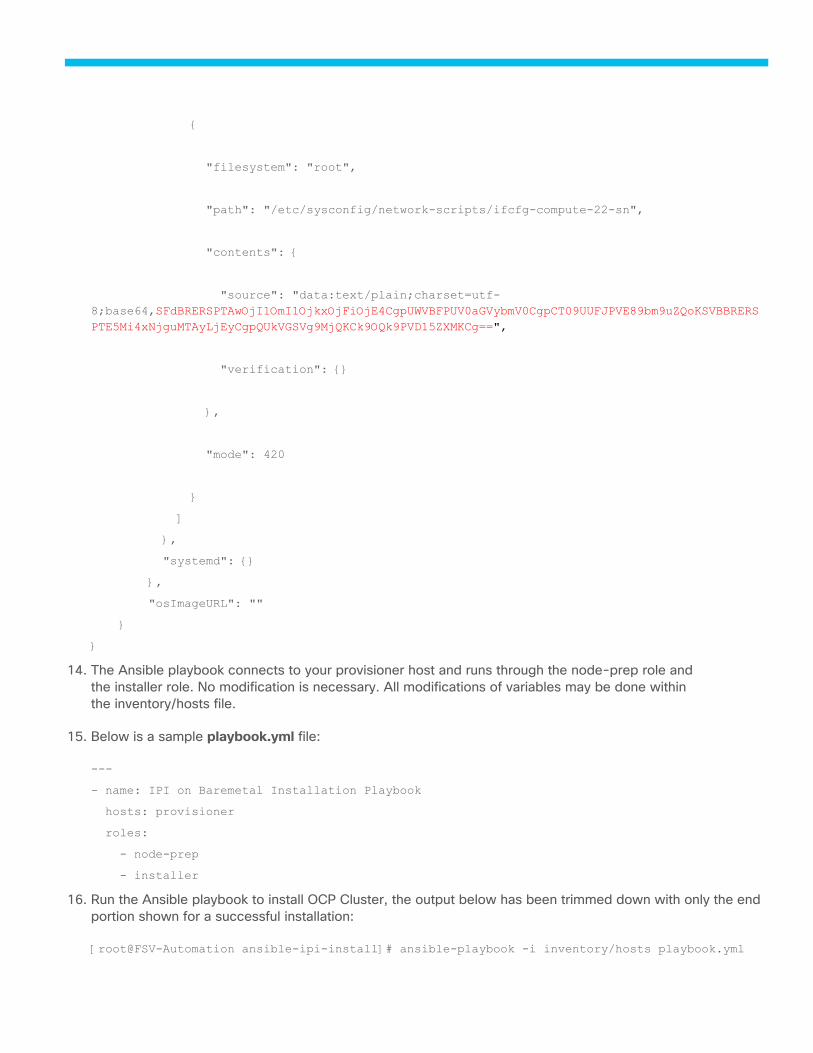
{
"filesystem": "root",
"path": "/etc/sysconfig/network-scripts/ifcfg-compute-22-sn",
"contents": {
"source": "data:text/plain;charset=utf-
8;base64,SFdBRERSPTAwOjI1OmI1OjkxOjFiOjE4CgpUWVBFPUV0aGVybmV0CgpCT09UUFJPVE89bm9uZQoKSVBBRERS
PTE5Mi4xNjguMTAyLjEyCgpQUkVGSVg9MjQKCk9OQk9PVD15ZXMKCg==",
"verification": {}
},
"mode": 420
}
]
},
"systemd": {}
},
"osImageURL": ""
}
}
14. The Ansible playbook connects to your provisioner host and runs through the node-prep role and
the installer role. No modification is necessary. All modifications of variables may be done within
the inventory/hosts file.
15. Below is a sample playbook.yml file:
---
- name: IPI on Baremetal Installation Playbook
hosts: provisioner
roles:
- node-prep
- installer
16. Run the Ansible playbook to install OCP Cluster, the output below has been trimmed down with only the end
portion shown for a successful installation:
[root@FSV-Automation ansible-ipi-install]# ansible-playbook -i inventory/hosts playbook.yml
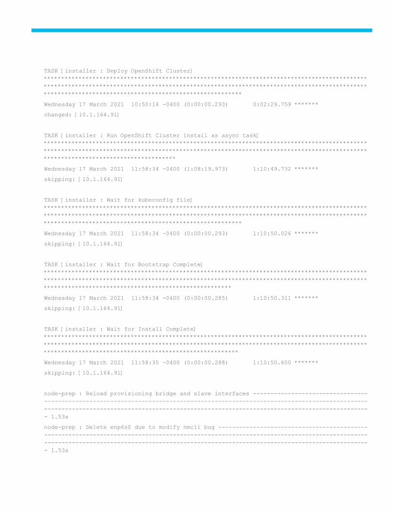
TASK [installer : Deploy OpenShift Cluster]
*********************************************************************************************
*********************************************************************************************
*********************************************************
Wednesday 17 March 2021 10:50:14 -0400 (0:00:00.293) 0:02:29.759 *******
changed: [10.1.164.91]
TASK [installer : Run OpenShift Cluster install as async task]
*********************************************************************************************
*********************************************************************************************
**************************************
Wednesday 17 March 2021 11:58:34 -0400 (1:08:19.973) 1:10:49.732 *******
skipping: [10.1.164.91]
TASK [installer : Wait for kubeconfig file]
*********************************************************************************************
*********************************************************************************************
*********************************************************
Wednesday 17 March 2021 11:58:34 -0400 (0:00:00.293) 1:10:50.026 *******
skipping: [10.1.164.91]
TASK [installer : Wait for Bootstrap Complete]
*********************************************************************************************
*********************************************************************************************
******************************************************
Wednesday 17 March 2021 11:58:34 -0400 (0:00:00.285) 1:10:50.311 *******
skipping: [10.1.164.91]
TASK [installer : Wait for Install Complete]
*********************************************************************************************
*********************************************************************************************
********************************************************
Wednesday 17 March 2021 11:58:35 -0400 (0:00:00.288) 1:10:50.600 *******
skipping: [10.1.164.91]
node-prep : Reload provisioning bridge and slave interfaces ---------------------------------
---------------------------------------------------------------------------------------------
---------------------------------------------------------------------------------------------
- 1.53s
node-prep : Delete enp6s0 due to modify nmcli bug -------------------------------------------
---------------------------------------------------------------------------------------------
---------------------------------------------------------------------------------------------
- 1.53s

installer : Generate install-config.yaml ----------------------------------------------------
---------------------------------------------------------------------------------------------
---------------------------------------------------------------------------------------------
- 1.50s
node-prep : Define Storage Pool for default -------------------------------------------------
---------------------------------------------------------------------------------------------
---------------------------------------------------------------------------------------------
- 1.45s
installer : Remove any existing /usr/local/bin OpenShift binaries ---------------------------
---------------------------------------------------------------------------------------------
---------------------------------------------------------------------------------------------
- 1.34s
installer : Ensure the manifests dir is owned by {{ ansible_user }} -------------------------
---------------------------------------------------------------------------------------------
---------------------------------------------------------------------------------------------
- 1.30s
[root@FSV-Automation ansible-ipi-install]#
17. Once the playbook has successfully completed, verify that your environment is up and running.
18. Log into the provisioner node:
[root@FSV-Automation]# ssh [email protected]
19. Export the kubeconfig file located in the ~/clusterconfigs/auth directory
[kni@provisioner ~]$ export KUBECONFIG=~/ocp4/clusterconfigs/auth/kubeconfig
20. Verify the nodes in the OpenShift Cluster:
[kni@provisioner ~]$ oc get nodes
NAME STATUS ROLES AGE VERSION
openshift-master-0 Ready master 27m v1.20.0+5fbfd19
openshift-master-1 Ready master 27m v1.20.0+5fbfd19
openshift-master-2 Ready master 27m v1.20.0+5fbfd19
openshift-worker-0 Ready worker 2m43s v1.20.0+5fbfd19
openshift-worker-1 Ready worker 2m30s v1.20.0+5fbfd19
21. Check the overall status by issuing the tail command to the .openshift_install.log log file in the install directo-
ry folder
[root@provisioner ~]# tail -f /home/kni/ocp4/clusterconfigs/.openshift_install.log
time="2021-03-17T11:58:33-04:00" level=debug msg="Cluster is initialized"
time="2021-03-17T11:58:33-04:00" level=info msg="Waiting up to 10m0s for the openshift-
console route to be created..."
time="2021-03-17T11:58:34-04:00" level=debug msg="Route found in openshift-console namespace:
console"
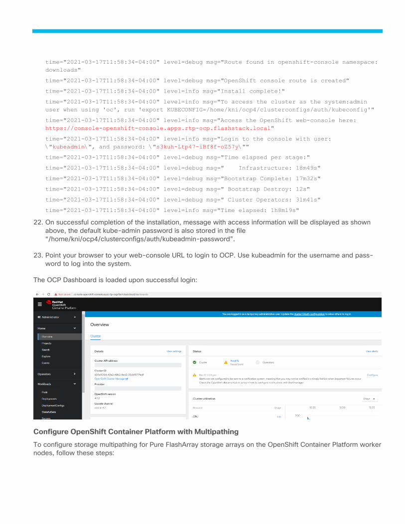
time="2021-03-17T11:58:34-04:00" level=debug msg="Route found in openshift-console namespace:
downloads"
time="2021-03-17T11:58:34-04:00" level=debug msg="OpenShift console route is created"
time="2021-03-17T11:58:34-04:00" level=info msg="Install complete!"
time="2021-03-17T11:58:34-04:00" level=info msg="To access the cluster as the system:admin
user when using 'oc', run 'export KUBECONFIG=/home/kni/ocp4/clusterconfigs/auth/kubeconfig'"
time="2021-03-17T11:58:34-04:00" level=info msg="Access the OpenShift web-console here:
https://console-openshift-console.apps.rtp-ocp.flashstack.local"
time="2021-03-17T11:58:34-04:00" level=info msg="Login to the console with user:
\"kubeadmin\", and password: \"s3kuh-Ltp47-iBf8f-oZ57y\""
time="2021-03-17T11:58:34-04:00" level=debug msg="Time elapsed per stage:"
time="2021-03-17T11:58:34-04:00" level=debug msg=" Infrastructure: 18m49s"
time="2021-03-17T11:58:34-04:00" level=debug msg="Bootstrap Complete: 17m32s"
time="2021-03-17T11:58:34-04:00" level=debug msg=" Bootstrap Destroy: 12s"
time="2021-03-17T11:58:34-04:00" level=debug msg=" Cluster Operators: 31m41s"
time="2021-03-17T11:58:34-04:00" level=info msg="Time elapsed: 1h8m19s"
22. On successful completion of the installation, message with access information will be displayed as shown
above, the default kube-admin password is also stored in the file
“/home/kni/ocp4/clusterconfigs/auth/kubeadmin-password”.
23. Point your browser to your web-console URL to login to OCP. Use kubeadmin for the username and pass-
word to log into the system.
The OCP Dashboard is loaded upon successful login:
Configure OpenShift Container Platform with Multipathing
To configure storage multipathing for Pure FlashArray storage arrays on the OpenShift Container Platform worker
nodes, follow these steps:

1. Download the 99-pure-storage-attach.yaml file, it is used to apply the configuration on the worker nodes
via machine config operator.
[kni@provisioner ~]$ sudo curl -O https://raw.githubusercontent.com/purestorage/pso-
csi/master/docs/99-pure-storage-attach.yaml
% Total % Received % Xferd Average Speed Time Time Time Current
Dload Upload Total Spent Left Speed
100 3946 100 3946 0 0 80530 0 --:--:-- --:--:-- --:--:-- 80530
The 99-pure-storage-attach.yaml file used below overrides any multipath configuration file that al-
ready exist on your systems. If a multipath configuration file already exists on your worker nodes, edit the
yaml file as noted.
2. Apply the YAML file.
[kni@provisioner ~]$ oc apply -f 99-pure-storage-attach.yaml
machineconfig.machineconfiguration.openshift.io/99-pure-storage-attach created
3. This creates a new machineconfiguration that the machine config operator detects and applies to all the
worker nodes. Wait for the worker nodes to reboot and for the configuration to take effect.
4. For each of the worker node verify the following:
[kni@provisioner ~]$ ssh core@openshift-worker-0
5. Ensure that multipath.conf file has been created and contains information for Pure Storage devices:
[core@openshift-worker-0 ~]$ cat /etc/multipath.conf
6. Ensure that the two udev rules files below have been created:
/etc/udev/rules.d/99-pure-storage.rules
/etc/udev/rules.d/90-scsi-ua.rules
7. Login to provisioner node and install Helm client
8. Install go tool-set on the provisioner node
[kni@provisioner ~]$ sudo yum module -y install go-toolset
9. Install Helm client as follows:
[kni@provisioner ~]$ sudo git clone https://github.com/helm/helm.git
[kni@provisioner ~]$ cd helm
[kni@provisioner helm]$ sudo make
Install Pure Service Orchestrator (PSO)
Install Pure Service Orchestrator from the provisioner node or from a node that has the OpenShift Command-line
interface installed. To install PSO, follow these steps:
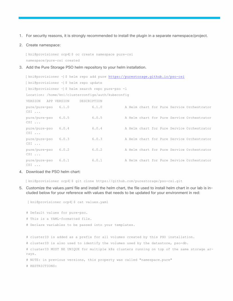
1. For security reasons, it is strongly recommended to install the plugin in a separate namespace/project.
2. Create namespace:
[kni@provisioner ocp4]$ oc create namespace pure-csi
namespace/pure-csi created
3. Add the Pure Storage PSO helm repository to your helm installation.
[kni@provisioner ~]$ helm repo add pure https://purestorage.github.io/pso-csi
[kni@provisioner ~]$ helm repo update
[kni@provisioner ~]$ helm search repo pure-pso -l
Location: /home/kni/clusterconfigs/auth/kubeconfig
VERSION APP VERSION DESCRIPTION
pure/pure-pso 6.1.0 6.1.0 A Helm chart for Pure Service Orchestrator
CSI ...
pure/pure-pso 6.0.5 6.0.5 A Helm chart for Pure Service Orchestrator
CSI ...
pure/pure-pso 6.0.4 6.0.4 A Helm chart for Pure Service Orchestrator
CSI ...
pure/pure-pso 6.0.3 6.0.3 A Helm chart for Pure Service Orchestrator
CSI ...
pure/pure-pso 6.0.2 6.0.2 A Helm chart for Pure Service Orchestrator
CSI ...
pure/pure-pso 6.0.1 6.0.1 A Helm chart for Pure Service Orchestrator
CSI ...
4. Download the PSO helm chart:
[kni@provisioner ocp4]$ git clone https://github.com/purestorage/pso-csi.git
5. Customize the values.yaml file and install the helm chart, the file used to install helm chart in our lab is in-
cluded below for your reference with values that needs to be updated for your environment in red:
[kni@provisioner ocp4]$ cat values.yaml
# Default values for pure-pso.
# This is a YAML-formatted file.
# Declare variables to be passed into your templates.
# clusterID is added as a prefix for all volumes created by this PSO installation.
# clusterID is also used to identify the volumes used by the datastore, pso-db.
# clusterID MUST BE UNIQUE for multiple k8s clusters running on top of the same storage ar-
rays.
# NOTE: in previous versions, this property was called "namespace.pure"
# RESTRICTIONS:
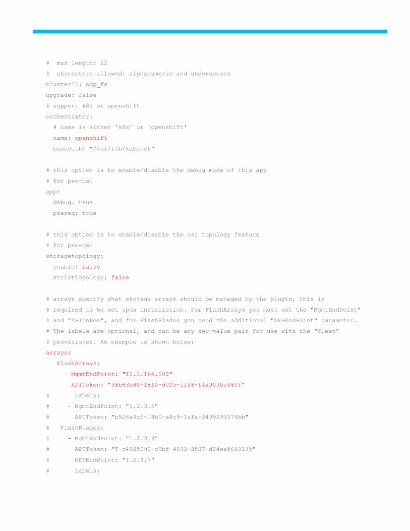
# max length: 22
# characters allowed: alphanumeric and underscores
clusterID: ocp_fs
upgrade: false
# support k8s or openshift
orchestrator:
# name is either 'k8s' or 'openshift'
name: openshift
basePath: "/var/lib/kubelet"
# this option is to enable/disable the debug mode of this app
# for pso-csi
app:
debug: true
prereq: true
# this option is to enable/disable the csi topology feature
# for pso-csi
storagetopology:
enable: false
strictTopology: false
# arrays specify what storage arrays should be managed by the plugin, this is
# required to be set upon installation. For FlashArrays you must set the "MgmtEndPoint"
# and "APIToken", and for FlashBlades you need the additional "NFSEndPoint" parameter.
# The labels are optional, and can be any key-value pair for use with the "fleet"
# provisioner. An example is shown below:
arrays:
FlashArrays:
- MgmtEndPoint: "10.2.164.100"
APIToken: "38b63b80-18f0-d025-1f28-f429030e482f"
# Labels:
# - MgmtEndPoint: "1.2.3.5"
# APIToken: "b526a4c6-18b0-a8c9-1afa-3499293574bb"
# FlashBlades:
# - MgmtEndPoint: "1.2.3.6"
# APIToken: "T-c4925090-c9bf-4033-8537-d24ee5669135"
# NFSEndPoint: "1.2.3.7"
# Labels:
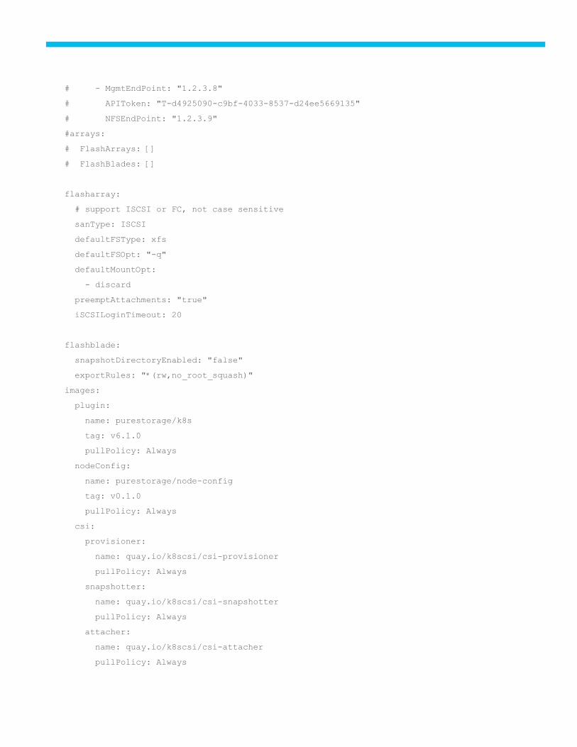
# - MgmtEndPoint: "1.2.3.8"
# APIToken: "T-d4925090-c9bf-4033-8537-d24ee5669135"
# NFSEndPoint: "1.2.3.9"
#arrays:
# FlashArrays: []
# FlashBlades: []
flasharray:
# support ISCSI or FC, not case sensitive
sanType: ISCSI
defaultFSType: xfs
defaultFSOpt: "-q"
defaultMountOpt:
- discard
preemptAttachments: "true"
iSCSILoginTimeout: 20
flashblade:
snapshotDirectoryEnabled: "false"
exportRules: "*(rw,no_root_squash)"
images:
plugin:
name: purestorage/k8s
tag: v6.1.0
pullPolicy: Always
nodeConfig:
name: purestorage/node-config
tag: v0.1.0
pullPolicy: Always
csi:
provisioner:
name: quay.io/k8scsi/csi-provisioner
pullPolicy: Always
snapshotter:
name: quay.io/k8scsi/csi-snapshotter
pullPolicy: Always
attacher:
name: quay.io/k8scsi/csi-attacher
pullPolicy: Always
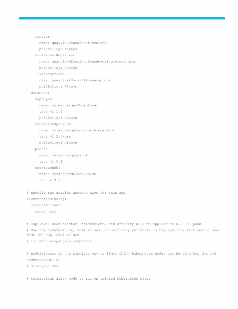
resizer:
name: quay.io/k8scsi/csi-resizer
pullPolicy: Always
nodeDriverRegistrar:
name: quay.io/k8scsi/csi-node-driver-registrar
pullPolicy: Always
livenessProbe:
name: quay.io/k8scsi/livenessprobe
pullPolicy: Always
database:
deployer:
name: purestorage/dbdeployer
tag: v1.1.0
pullPolicy: Always
cockroachOperator:
name: purestorage/cockroach-operator
tag: v1.2.0-pre
pullPolicy: Always
psctl:
name: purestorage/psctl
tag: v1.0.4
cockroachdb:
name: cockroachdb/cockroach
tag: v19.2.3
# specify the service account name for this app
clusterrolebinding:
serviceAccount:
name: pure
# Top-level nodeSelector, tolerations, and affinity will be applied to all PSO pods
# Use the nodeSelector, tolerations, and affinity variables in the specific sections to over-
ride the top-level values
# for each respective component
# nodeSelector is the simplest way to limit which kubernetes nodes can be used for the pod
nodeSelector: {}
# disktype: ssd
# tolerations allow pods to run on tainted kubernetes nodes
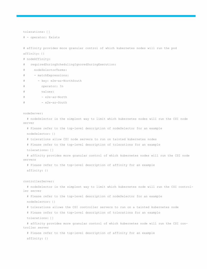
tolerations: []
# - operator: Exists
# affinity provides more granular control of which kubernetes nodes will run the pod
affinity: {}
# nodeAffinity:
# requiredDuringSchedulingIgnoredDuringExecution:
# nodeSelectorTerms:
# - matchExpressions:
# - key: e2e-az-NorthSouth
# operator: In
# values:
# - e2e-az-North
# - e2e-az-South
nodeServer:
# nodeSelector is the simplest way to limit which kubernetes nodes will run the CSI node
server
# Please refer to the top-level description of nodeSelector for an example
nodeSelector: {}
# tolerations allow CSI node servers to run on tainted kubernetes nodes
# Please refer to the top-level description of tolerations for an example
tolerations: []
# affinity provides more granular control of which kubernetes nodes will run the CSI node
servers
# Please refer to the top-level description of affinity for an example
affinity: {}
controllerServer:
# nodeSelector is the simplest way to limit which kubernetes node will run the CSI control-
ler server
# Please refer to the top-level description of nodeSelector for an example
nodeSelector: {}
# tolerations allows the CSI controller servers to run on a tainted kubernetes node
# Please refer to the top-level description of tolerations for an example
tolerations: []
# affinity provides more granular control of which kubernetes node will run the CSI con-
troller server
# Please refer to the top-level description of affinity for an example
affinity: {}

database:
# nodeSelector is the simplest way to limit which kubernetes nodes will run the database-
related pods
# Please refer to the top-level description of nodeSelector for an example
nodeSelector: {}
# tolerations allows the database-related pods to run on tainted kubernetes nodes
# Please refer to the top-level description of tolerations for an example
tolerations: []
# affinity provides more granular control of which kubernetes nodes will run the database-
related pods
# Please refer to the top-level description of affinity for an example
affinity: {}
# resources is used specifically for the database pods
# Change these to appropriate values for the hardware that you're running. You can see
# the amount of allocatable resources on each of your Kubernetes nodes by running:
# kubectl describe nodes
resources:
limits:
memory: "1Gi"
# cpu: "1"
# requests:
# memory: "1Gi"
# cpu: "1"
# The length of time a db node is considered Suspect before being marked as Down
# This value is recommended to be larger than Kubernetes liveness probe setting time in our
db pod,
# so K8S gets chance to restart the pod if it's unhealthy before we take it down.
# https://kubernetes.io/docs/tasks/configure-pod-container/configure-liveness-readiness-
startup-probes/#configure-probes
maxSuspectSeconds: 1800
# The length of time a db node is allowed to be in Startup before being suspect
maxStartupSeconds: 600
6. Dry run the installation to validate your values.yaml and check it is working correctly:
[kni@provisioner ~]$ helm install pure-pso pure/pure-pso --namespace pure-csi -f values.yaml
--dry-run –-debug
7. Once verified, run the install:
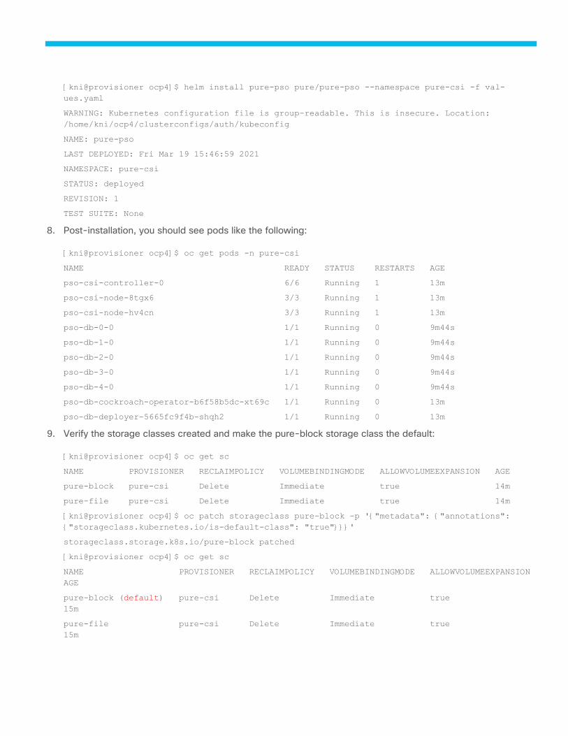
[kni@provisioner ocp4]$ helm install pure-pso pure/pure-pso --namespace pure-csi -f val-
ues.yaml
WARNING: Kubernetes configuration file is group-readable. This is insecure. Location:
/home/kni/ocp4/clusterconfigs/auth/kubeconfig
NAME: pure-pso
LAST DEPLOYED: Fri Mar 19 15:46:59 2021
NAMESPACE: pure-csi
STATUS: deployed
REVISION: 1
TEST SUITE: None
8. Post-installation, you should see pods like the following:
[kni@provisioner ocp4]$ oc get pods -n pure-csi
NAME READY STATUS RESTARTS AGE
pso-csi-controller-0 6/6 Running 1 13m
pso-csi-node-8tgx6 3/3 Running 1 13m
pso-csi-node-hv4cn 3/3 Running 1 13m
pso-db-0-0 1/1 Running 0 9m44s
pso-db-1-0 1/1 Running 0 9m44s
pso-db-2-0 1/1 Running 0 9m44s
pso-db-3-0 1/1 Running 0 9m44s
pso-db-4-0 1/1 Running 0 9m44s
pso-db-cockroach-operator-b6f58b5dc-xt69c 1/1 Running 0 13m
pso-db-deployer-5665fc9f4b-shqh2 1/1 Running 0 13m
9. Verify the storage classes created and make the pure-block storage class the default:
[kni@provisioner ocp4]$ oc get sc
NAME PROVISIONER RECLAIMPOLICY VOLUMEBINDINGMODE ALLOWVOLUMEEXPANSION AGE
pure-block pure-csi Delete Immediate true 14m
pure-file pure-csi Delete Immediate true 14m
[kni@provisioner ocp4]$ oc patch storageclass pure-block -p '{"metadata": {"annotations":
{"storageclass.kubernetes.io/is-default-class": "true"}}}'
storageclass.storage.k8s.io/pure-block patched
[kni@provisioner ocp4]$ oc get sc
NAME PROVISIONER RECLAIMPOLICY VOLUMEBINDINGMODE ALLOWVOLUMEEXPANSION
AGE
pure-block (default) pure-csi Delete Immediate true
15m
pure-file pure-csi Delete Immediate true
15m
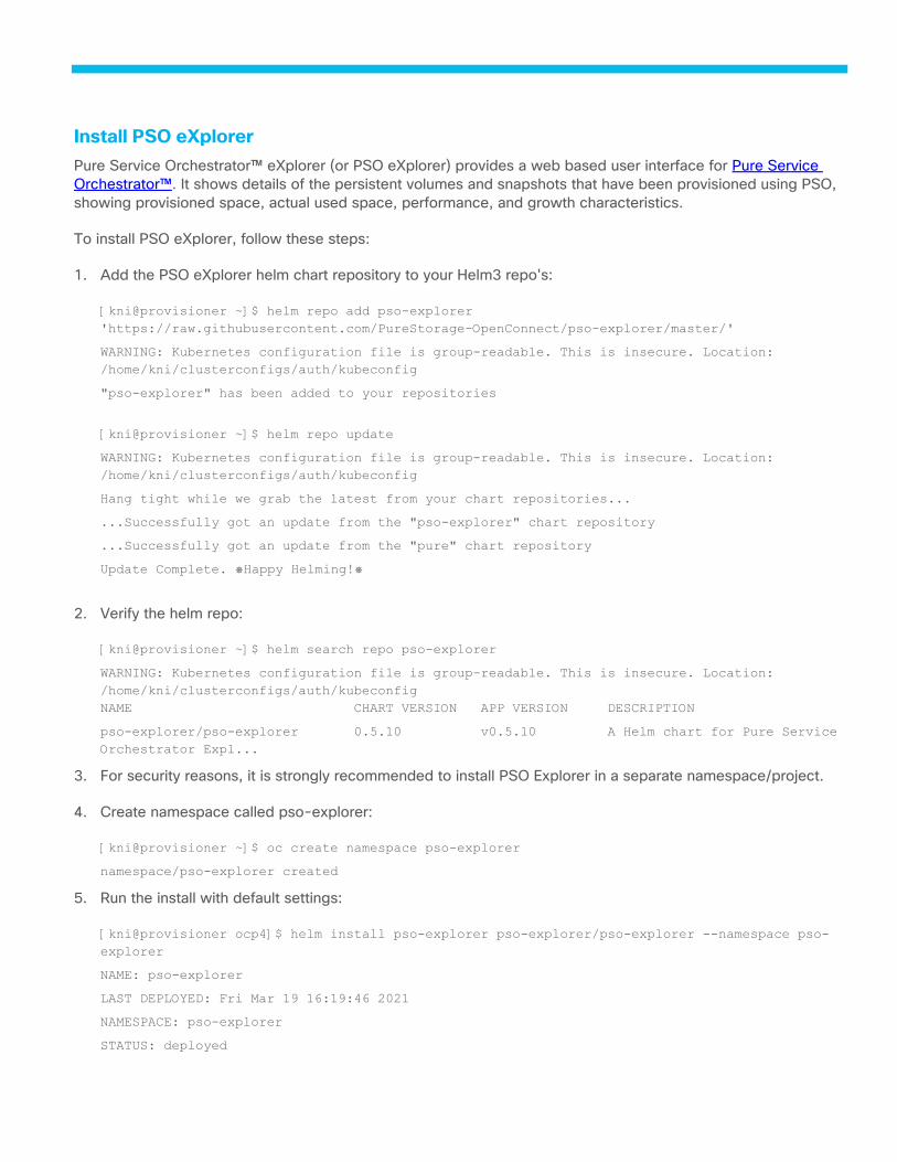
Install PSO eXplorer
Pure Service Orchestrator™ eXplorer (or PSO eXplorer) provides a web based user interface for Pure Service
Orchestrator™. It shows details of the persistent volumes and snapshots that have been provisioned using PSO,
showing provisioned space, actual used space, performance, and growth characteristics.
To install PSO eXplorer, follow these steps:
1. Add the PSO eXplorer helm chart repository to your Helm3 repo's:
[kni@provisioner ~]$ helm repo add pso-explorer
'https://raw.githubusercontent.com/PureStorage-OpenConnect/pso-explorer/master/'
WARNING: Kubernetes configuration file is group-readable. This is insecure. Location:
/home/kni/clusterconfigs/auth/kubeconfig
"pso-explorer" has been added to your repositories
[kni@provisioner ~]$ helm repo update
WARNING: Kubernetes configuration file is group-readable. This is insecure. Location:
/home/kni/clusterconfigs/auth/kubeconfig
Hang tight while we grab the latest from your chart repositories...
...Successfully got an update from the "pso-explorer" chart repository
...Successfully got an update from the "pure" chart repository
Update Complete. ⎈Happy Helming!⎈
2. Verify the helm repo:
[kni@provisioner ~]$ helm search repo pso-explorer
WARNING: Kubernetes configuration file is group-readable. This is insecure. Location:
/home/kni/clusterconfigs/auth/kubeconfig
NAME CHART VERSION APP VERSION DESCRIPTION
pso-explorer/pso-explorer 0.5.10 v0.5.10 A Helm chart for Pure Service
Orchestrator Expl...
3. For security reasons, it is strongly recommended to install PSO Explorer in a separate namespace/project.
4. Create namespace called pso-explorer:
[kni@provisioner ~]$ oc create namespace pso-explorer
namespace/pso-explorer created
5. Run the install with default settings:
[kni@provisioner ocp4]$ helm install pso-explorer pso-explorer/pso-explorer --namespace pso-
explorer
NAME: pso-explorer
LAST DEPLOYED: Fri Mar 19 16:19:46 2021
NAMESPACE: pso-explorer
STATUS: deployed
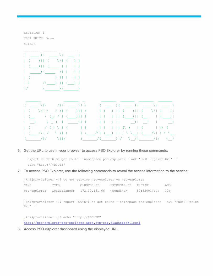
REVISION: 1
TEST SUITE: None
NOTES:
_______ _______ _______
( ____ )( ____ \( ___ )
| ( )|| ( \/| ( ) |
| (____)|| (_____ | | | |
| _____)(_____ )| | | |
| ( ) || | | |
| ) /\____) || (___) |
|/ \_______)(_______)
_______ _______ _ _______ _______ _______ _______
( ____ \|\ /|( ____ )( \ ( ___ )( ____ )( ____ \( ____ )
| ( \/( \ / )| ( )|| ( | ( ) || ( )|| ( \/| ( )|
| (__ \ (_) / | (____)|| | | | | || (____)|| (__ | (____)|
| __) ) _ ( | _____)| | | | | || __)| __) | __)
| ( / ( ) \ | ( | | | | | || (\ ( | ( | (\ (
| (____/\( / \ )| ) | (____/\| (___) || ) \ \__| (____/\| ) \ \__
(_______/|/ \||/ (_______/(_______)|/ \__/(_______/|/ \__/
6. Get the URL to use in your browser to access PSO Explorer by running these commands:
export ROUTE=$(oc get route --namespace pso-explorer | awk 'FNR>1 {print $2}' -)
echo "http://$ROUTE"
7. To access PSO Explorer, use the following commands to reveal the access information to the service:
[kni@provisioner ~]$ oc get service pso-explorer -n pso-explorer
NAME TYPE CLUSTER-IP EXTERNAL-IP PORT(S) AGE
pso-explorer LoadBalancer 172.30.131.66 <pending> 80:32001/TCP 33s
[kni@provisioner ~]$ export ROUTE=$(oc get route --namespace pso-explorer | awk 'FNR>1 {print
$2}' -)
[kni@provisioner ~]$ echo "http://$ROUTE"
http://pso-explorer-pso-explorer.apps.rtp-ocp.flashstack.local
8. Access PSO eXplorer dashboard using the displayed URL.
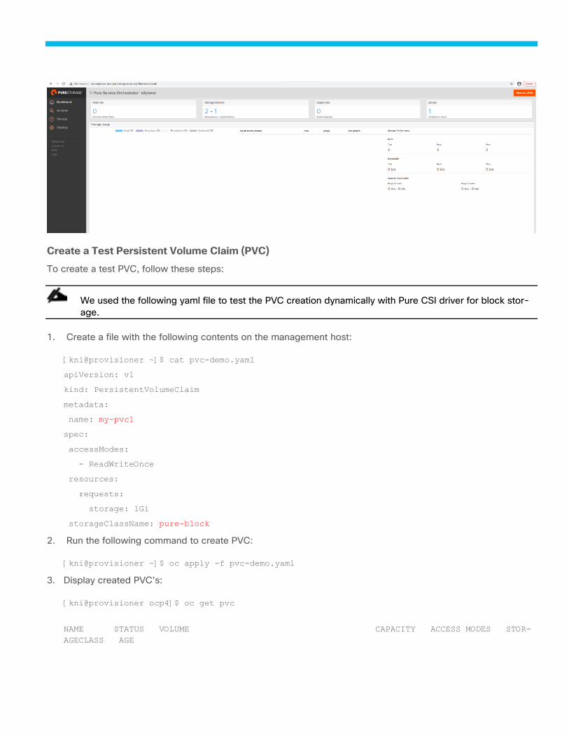
Create a Test Persistent Volume Claim (PVC)
To create a test PVC, follow these steps:
We used the following yaml file to test the PVC creation dynamically with Pure CSI driver for block stor-
age.
1. Create a file with the following contents on the management host:
[kni@provisioner ~]$ cat pvc-demo.yaml
apiVersion: v1
kind: PersistentVolumeClaim
metadata:
name: my-pvc1
spec:
accessModes:
- ReadWriteOnce
resources:
requests:
storage: 1Gi
storageClassName: pure-block
2. Run the following command to create PVC:
[kni@provisioner ~]$ oc apply -f pvc-demo.yaml
3. Display created PVC’s:
[kni@provisioner ocp4]$ oc get pvc
NAME STATUS VOLUME CAPACITY ACCESS MODES STOR-
AGECLASS AGE
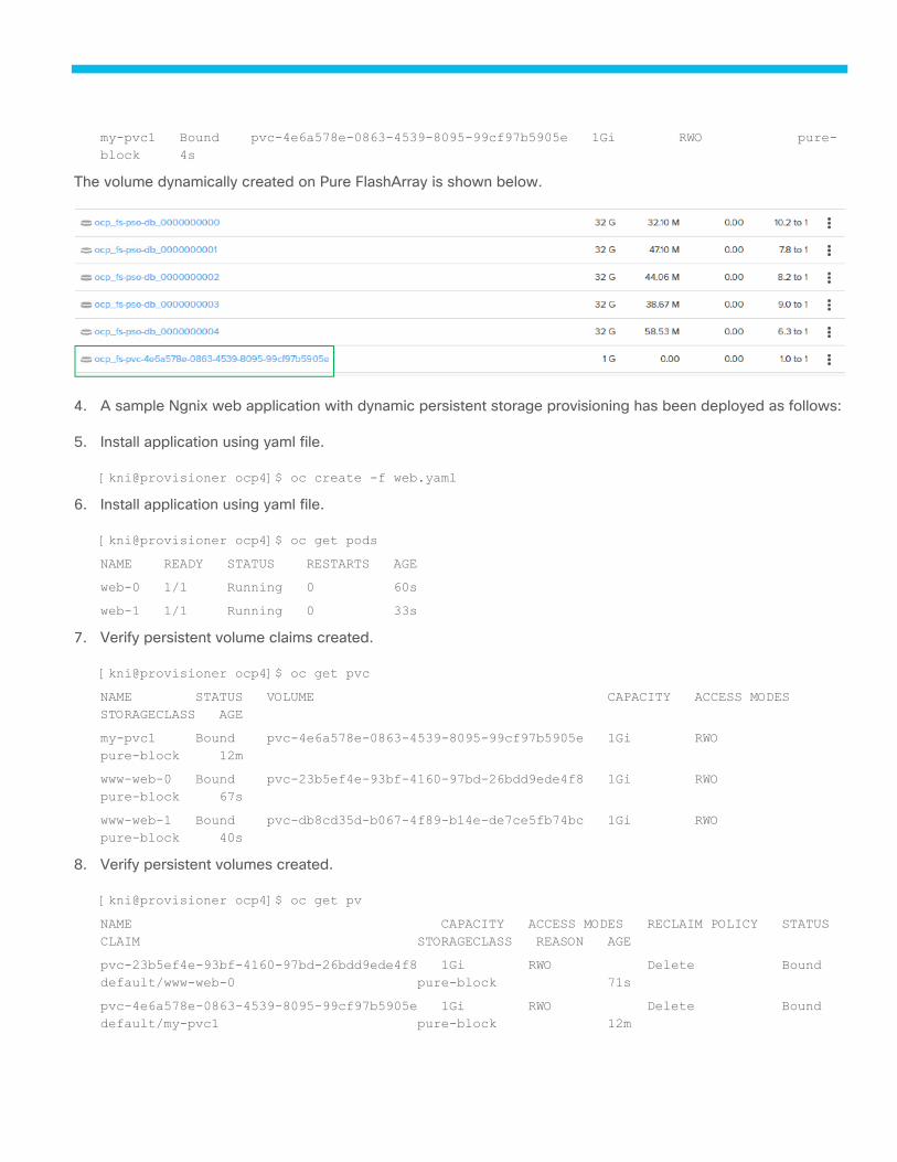
my-pvc1 Bound pvc-4e6a578e-0863-4539-8095-99cf97b5905e 1Gi RWO pure-
block 4s
The volume dynamically created on Pure FlashArray is shown below.
4. A sample Ngnix web application with dynamic persistent storage provisioning has been deployed as follows:
5. Install application using yaml file.
[kni@provisioner ocp4]$ oc create -f web.yaml
6. Install application using yaml file.
[kni@provisioner ocp4]$ oc get pods
NAME READY STATUS RESTARTS AGE
web-0 1/1 Running 0 60s
web-1 1/1 Running 0 33s
7. Verify persistent volume claims created.
[kni@provisioner ocp4]$ oc get pvc
NAME STATUS VOLUME CAPACITY ACCESS MODES
STORAGECLASS AGE
my-pvc1 Bound pvc-4e6a578e-0863-4539-8095-99cf97b5905e 1Gi RWO
pure-block 12m
www-web-0 Bound pvc-23b5ef4e-93bf-4160-97bd-26bdd9ede4f8 1Gi RWO
pure-block 67s
www-web-1 Bound pvc-db8cd35d-b067-4f89-b14e-de7ce5fb74bc 1Gi RWO
pure-block 40s
8. Verify persistent volumes created.
[kni@provisioner ocp4]$ oc get pv
NAME CAPACITY ACCESS MODES RECLAIM POLICY STATUS
CLAIM STORAGECLASS REASON AGE
pvc-23b5ef4e-93bf-4160-97bd-26bdd9ede4f8 1Gi RWO Delete Bound
default/www-web-0 pure-block 71s
pvc-4e6a578e-0863-4539-8095-99cf97b5905e 1Gi RWO Delete Bound
default/my-pvc1 pure-block 12m
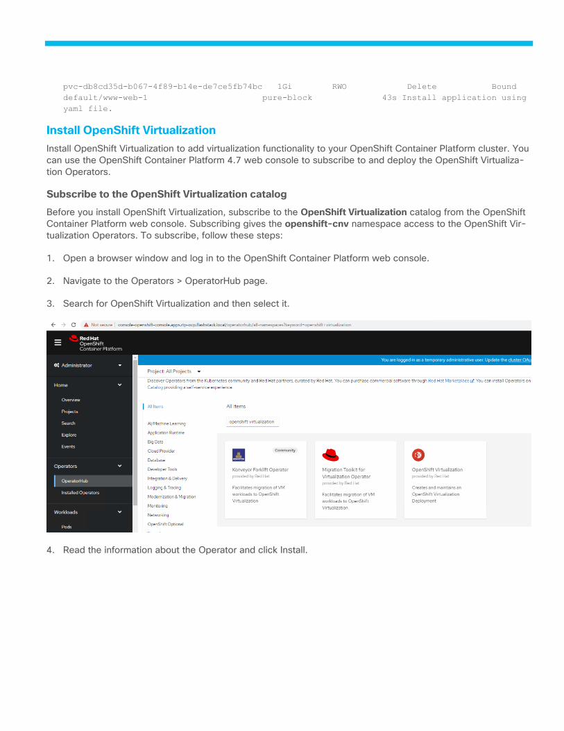
pvc-db8cd35d-b067-4f89-b14e-de7ce5fb74bc 1Gi RWO Delete Bound
default/www-web-1 pure-block 43s Install application using
yaml file.
Install OpenShift Virtualization
Install OpenShift Virtualization to add virtualization functionality to your OpenShift Container Platform cluster. You
can use the OpenShift Container Platform 4.7 web console to subscribe to and deploy the OpenShift Virtualiza-
tion Operators.
Subscribe to the OpenShift Virtualization catalog
Before you install OpenShift Virtualization, subscribe to the OpenShift Virtualization catalog from the OpenShift
Container Platform web console. Subscribing gives the openshift-cnv namespace access to the OpenShift Vir-
tualization Operators. To subscribe, follow these steps:
1. Open a browser window and log in to the OpenShift Container Platform web console.
2. Navigate to the Operators > OperatorHub page.
3. Search for OpenShift Virtualization and then select it.
4. Read the information about the Operator and click Install.
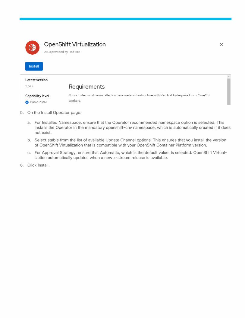
5. On the Install Operator page:
a. For Installed Namespace, ensure that the Operator recommended namespace option is selected. This
installs the Operator in the mandatory openshift-cnv namespace, which is automatically created if it does
not exist.
b. Select stable from the list of available Update Channel options. This ensures that you install the version
of OpenShift Virtualization that is compatible with your OpenShift Container Platform version.
c. For Approval Strategy, ensure that Automatic, which is the default value, is selected. OpenShift Virtual-
ization automatically updates when a new z-stream release is available.
6. Click Install.
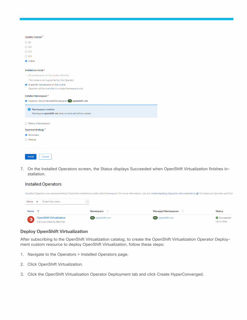
7. On the Installed Operators screen, the Status displays Succeeded when OpenShift Virtualization finishes in-
stallation.
Deploy OpenShift Virtualization
After subscribing to the OpenShift Virtualization catalog, to create the OpenShift Virtualization Operator Deploy-
ment custom resource to deploy OpenShift Virtualization, follow these steps:
1. Navigate to the Operators > Installed Operators page.
2. Click OpenShift Virtualization.
3. Click the OpenShift Virtualization Operator Deployment tab and click Create HyperConverged.
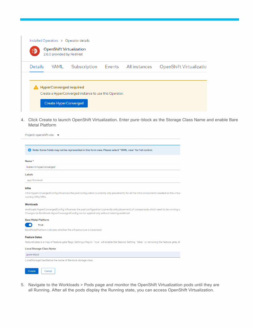
4. Click Create to launch OpenShift Virtualization. Enter pure-block as the Storage Class Name and enable Bare
Metal Platform
5. Navigate to the Workloads > Pods page and monitor the OpenShift Virtualization pods until they are
all Running. After all the pods display the Running state, you can access OpenShift Virtualization.
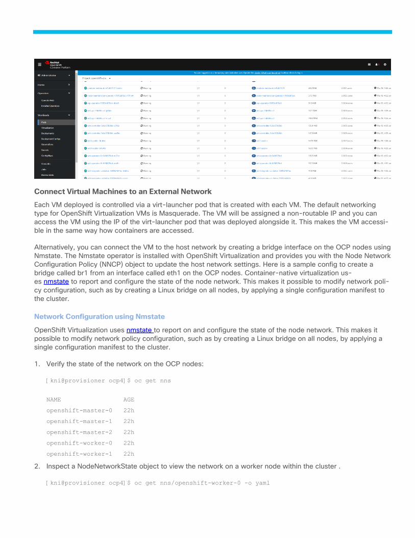
Connect Virtual Machines to an External Network
Each VM deployed is controlled via a virt-launcher pod that is created with each VM. The default networking
type for OpenShift Virtualization VMs is Masquerade. The VM will be assigned a non-routable IP and you can
access the VM using the IP of the virt-launcher pod that was deployed alongside it. This makes the VM accessi-
ble in the same way how containers are accessed.
Alternatively, you can connect the VM to the host network by creating a bridge interface on the OCP nodes using
Nmstate. The Nmstate operator is installed with OpenShift Virtualization and provides you with the Node Network
Configuration Policy (NNCP) object to update the host network settings. Here is a sample config to create a
bridge called br1 from an interface called eth1 on the OCP nodes. Container-native virtualization us-
es nmstate to report and configure the state of the node network. This makes it possible to modify network poli-
cy configuration, such as by creating a Linux bridge on all nodes, by applying a single configuration manifest to
the cluster.
Network Configuration using Nmstate
OpenShift Virtualization uses nmstate to report on and configure the state of the node network. This makes it
possible to modify network policy configuration, such as by creating a Linux bridge on all nodes, by applying a
single configuration manifest to the cluster.
1. Verify the state of the network on the OCP nodes:
[kni@provisioner ocp4]$ oc get nns
NAME AGE
openshift-master-0 22h
openshift-master-1 22h
openshift-master-2 22h
openshift-worker-0 22h
openshift-worker-1 22h
2. Inspect a NodeNetworkState object to view the network on a worker node within the cluster .
[kni@provisioner ocp4]$ oc get nns/openshift-worker-0 -o yaml

3. Create an interface on nodes in the cluster by applying a NodeNetworkConfigurationPolicy manifest to the
cluster. The manifest details the requested configuration for the interface. We will use the dedicated inter-
face we created on UCS for OpenShift virtualization.
By default, the manifest applies to all nodes in the cluster. To add the interface to specif-
ic nodes, add the spec: nodeSelector parameter and the appropriate <key>:<value> for your
node selector.
4. Create the NodeNetworkConfigurationPolicy manifest. The following example configures a new Linux bridge
on all worker nodes with one interface ens5f2 with no IP address assigned and name it br1:
[kni@provisioner ocp4]$ cat linux-bridge.yaml
apiVersion: nmstate.io/v1beta1
kind: NodeNetworkConfigurationPolicy
metadata:
name: worker-br1
spec:
nodeSelector:
kubernetes.io/worker: “”
desiredState:
interfaces:
- name: br1
description: Linux bridge with enp103s0f1 as a port
type: linux-bridge
state: up
ipv4:
dhcp: true
enabled: true
bridge:
options:
stp:
enabled: false
port:
- name: ens5f2
5. Create Linux bridge using nm state operator using the file created with contents shown in the previous step.
[kni@provisioner ocp4]$ oc apply -f linux-bridge.yaml
nodenetworkconfigurationpolicy.nmstate.io/worker-br1 created
6. Verify created node network policy using nnce:
[kni@provisioner ocp4]$ oc get nnce
NAME STATUS
openshift-master-0.worker-br1 NodeSelectorNotMatching
openshift-master-1.worker-br1 NodeSelectorNotMatching
openshift-master-2.worker-br1 NodeSelectorNotMatching
openshift-worker-0.worker-br1 SuccessfullyConfigured
openshift-worker-1.worker-br1 SuccessfullyConfigured
Create Network Attachment Definition
Create network attachment definition to allow VMs to be able to connect to external network using the dedicated
vNIC on the UCS.
1. In the OpenShift GUI console , click the Perspective switcher dropdown menu and select Administrator.
2. In the administrator view, from the side menu, click > Network Attachment Definitions. The Network Attach-
ment Definition screen lists your network attachment definitions.
3. Click Create Network Attachment Definition. The Create Network Attachment Definition page displays. Com-
plete the following fields based on the bridge configuration you created to connect to an external network.
4. Enter a Name for the network attachment definition.
5. Optionally, enter a Description of the network attachment definition.
6. From Network Type, select CNV Linux bridge.
7. Enter the Bridge name.
8. Optionally, enter the VLAN Tag Number.
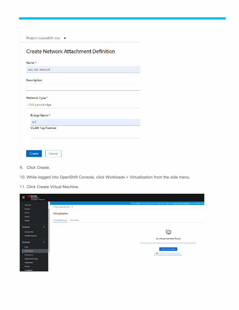
9. Click Create.
10. While logged into OpenShift Console, click Workloads > Virtualization from the side menu.
11. Click Create Virtual Machine.
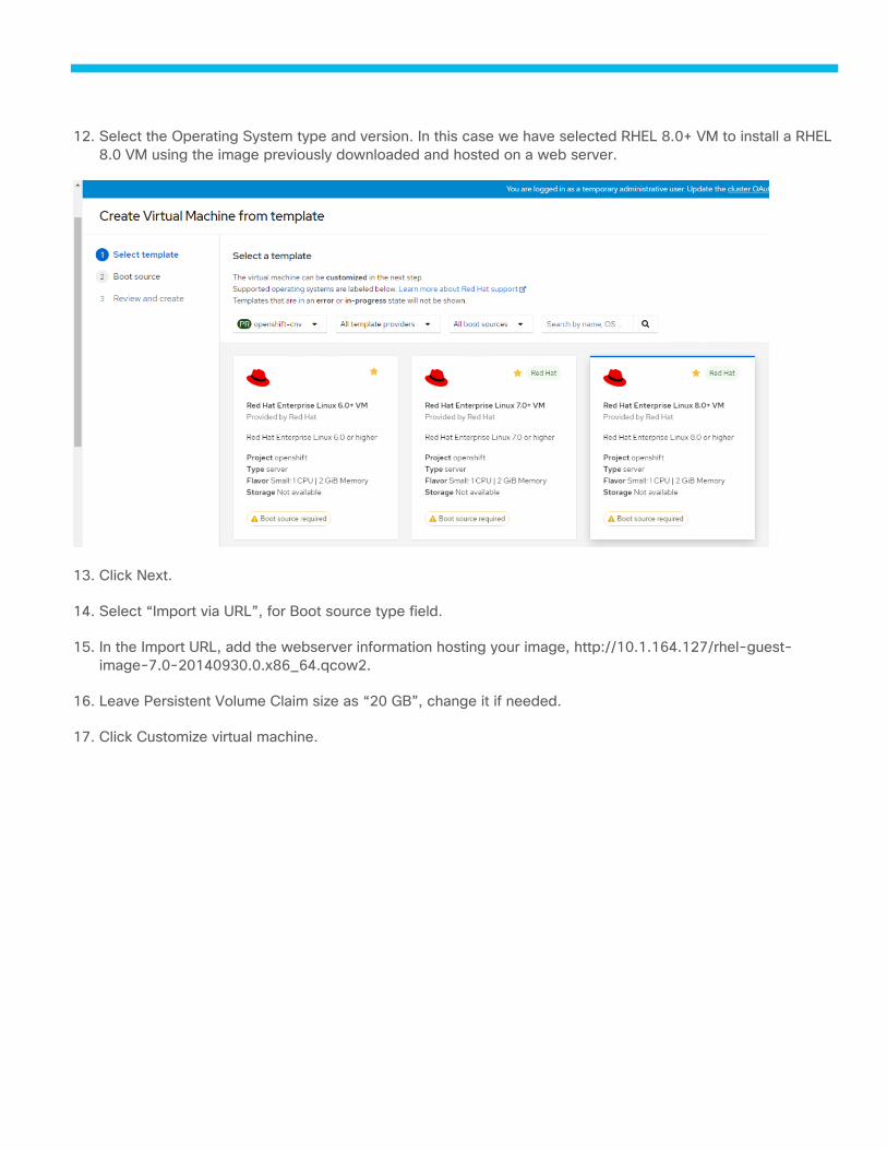
12. Select the Operating System type and version. In this case we have selected RHEL 8.0+ VM to install a RHEL
8.0 VM using the image previously downloaded and hosted on a web server.
13. Click Next.
14. Select “Import via URL”, for Boot source type field.
15. In the Import URL, add the webserver information hosting your image, http://10.1.164.127/rhel-guest-
image-7.0-20140930.0.x86_64.qcow2.
16. Leave Persistent Volume Claim size as “20 GB”, change it if needed.
17. Click Customize virtual machine.
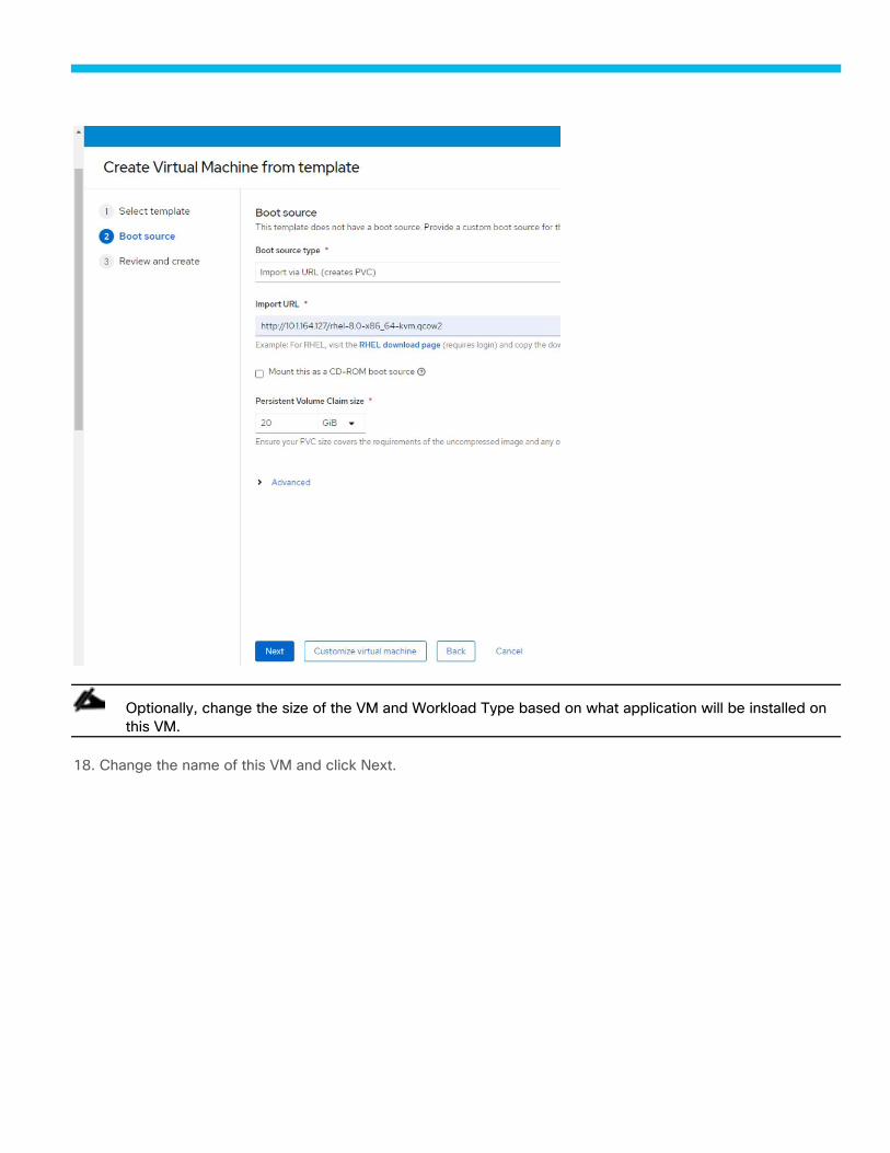
Optionally, change the size of the VM and Workload Type based on what application will be installed on
this VM.
18. Change the name of this VM and click Next.
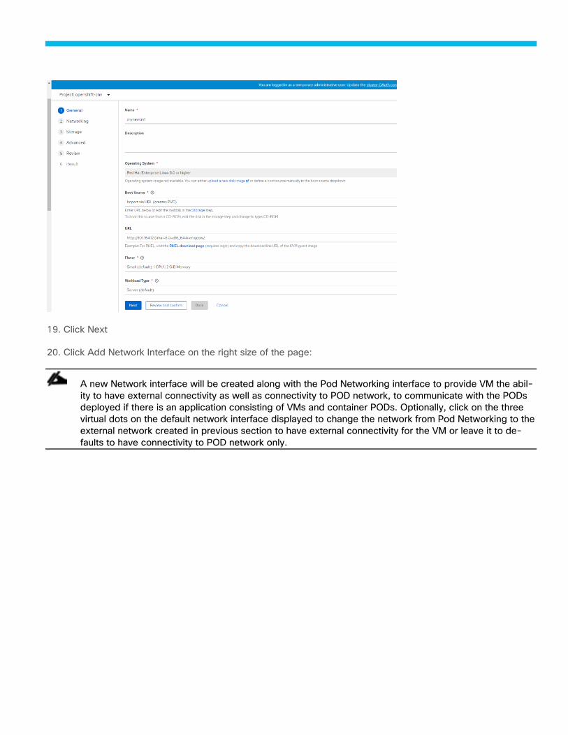
19. Click Next
20. Click Add Network Interface on the right size of the page:
A new Network interface will be created along with the Pod Networking interface to provide VM the abil-
ity to have external connectivity as well as connectivity to POD network, to communicate with the PODs
deployed if there is an application consisting of VMs and container PODs. Optionally, click on the three
virtual dots on the default network interface displayed to change the network from Pod Networking to the
external network created in previous section to have external connectivity for the VM or leave it to de-
faults to have connectivity to POD network only.
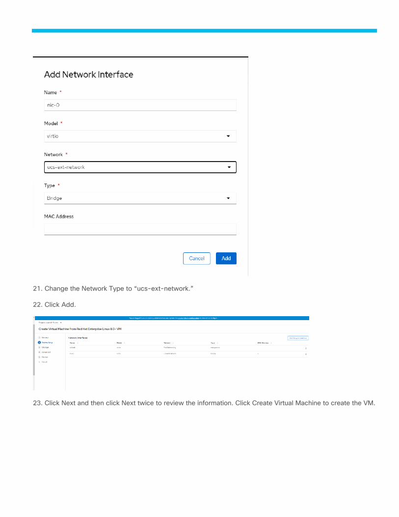
21. Change the Network Type to “ucs-ext-network.”
22. Click Add.
23. Click Next and then click Next twice to review the information. Click Create Virtual Machine to create the VM.
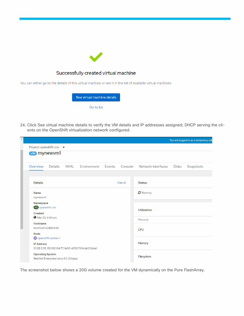
24. Click See virtual machine details to verify the VM details and IP addresses assigned; DHCP serving the cli-
ents on the OpenShift virtualization network configured.
The screenshot below shows a 20G volume created for the VM dynamically on the Pure FlashArray.
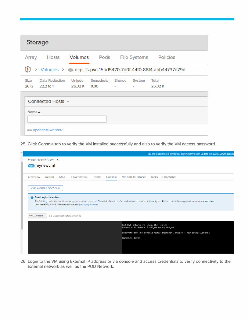
25. Click Console tab to verify the VM installed successfully and also to verify the VM access password.
26. Login to the VM using External IP address or via console and access credentials to verify connectivity to the
External network as well as the POD Network.
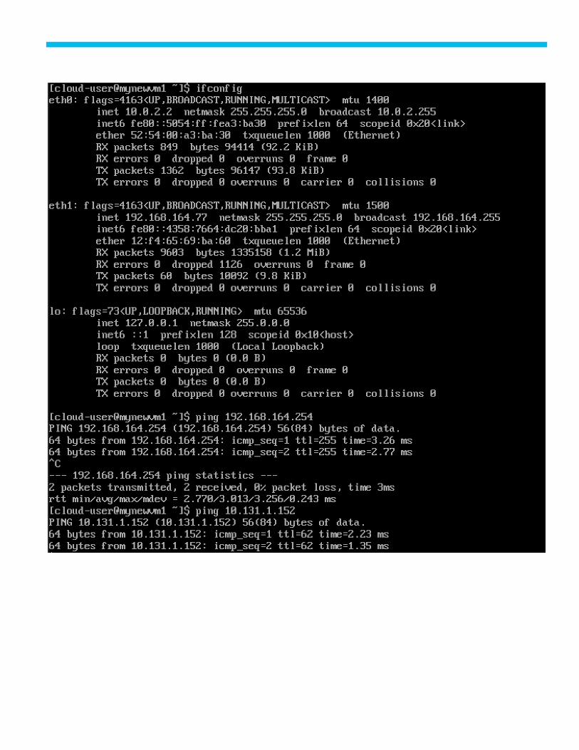
References
Products and Solutions
Cisco Unified Computing System:
http://www.cisco.com/en/US/products/ps10265/index.html
Cisco UCS 6400 Series Fabric Interconnects:
https://www.cisco.com/c/en/us/support/servers-unified-computing/ucs-6400-series-fabric-
interconnects/tsdproducts-support-series-home.html
Cisco UCS 5100 Series Blade Server Chassis:
http://www.isco.com/en/US/products/ps10279/index.html
Cisco UCS B-Series Blade Servers:
http://www.cisco.com/c/en/us/products/servers-unified-computing/ucs-b-series-blade-servers/index.html
Cisco UCS C-Series Rack Servers:
http://www.cisco.com/c/en/us/products/servers-unified-computing/ucs-c-series-rack-servers/index.html
Cisco UCS Adapters:
http://www.cisco.com/en/US/products/ps10277/prod_module_series_home.html
Cisco UCS Manager:
http://www.cisco.com/en/US/products/ps10281/index.html
Cisco Intersight:
https://www.cisco.com/c/en/us/products/servers-unified-computing/intersight/index.html
Cisco Nexus 9000 Series Switches:
http://www.cisco.com/c/en/us/support/switches/nexus-9000-series-switches/tsd-products-support-
serieshome.html
Pure FlashArray:
https://www.purestorage.com/products/nvme/flasharray-x.html
Pure PSO:
https://github.com/purestorage/pso-csi
Pure PSO explorer:

https://github.com/PureStorage-OpenConnect/pso-explorer
Red Hat OpenShift:
https://www.openshift.com/
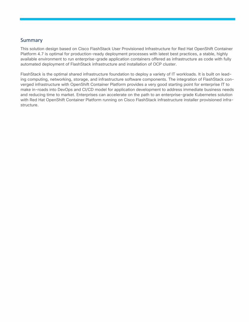
Summary
This solution design based on Cisco FlashStack User Provisioned Infrastructure for Red Hat OpenShift Container
Platform 4.7 is optimal for production-ready deployment processes with latest best practices, a stable, highly
available environment to run enterprise-grade application containers offered as infrastructure as code with fully
automated deployment of FlashStack infrastructure and installation of OCP cluster.
FlashStack is the optimal shared infrastructure foundation to deploy a variety of IT workloads. It is built on lead-
ing computing, networking, storage, and infrastructure software components. The integration of FlashStack con-
verged infrastructure with OpenShift Container Platform provides a very good starting point for enterprise IT to
make in-roads into DevOps and CI/CD model for application development to address immediate business needs
and reducing time to market. Enterprises can accelerate on the path to an enterprise-grade Kubernetes solution
with Red Hat OpenShift Container Platform running on Cisco FlashStack infrastructure installer provisioned infra-
structure.

About the Authors
Sreenivasa Edula, Technical Marketing Engineer, UCS Data Center Solutions Engineering, Cisco Systems, Inc.
Sreeni is a Technical Marketing Engineer in the Cisco UCS Data Center Solutions Engineering team focusing on
converged and hyper-converged infrastructure solutions, prior to that he worked as a Solutions Architect at EMC
Corporation. He has experience in Information Systems with expertise across Cisco Data Center technology
portfolio, including DC architecture design, virtualization, compute, network, storage, and cloud computing.
Simon Dodsley, Principal Field Solutions Architect, Pure Storage, Inc.
As Technical Director of New Stack, Simon is responsible for managing the direction of Pure Storage pertaining
to Open Source technologies including OpenStack, Containers, and associated orchestration and automation
toolsets. His responsibilities also include developing best practices, reference architectures and configuration
guides. With over 30 years of storage experience across all aspects of the discipline, from administration to ar-
chitectural design, Simon has worked with all major storage vendors’ technologies and organizations, large and
small, across Europe and the USA as both customer and service provider.
Acknowledgements
For their support and contribution to the design, validation, and creation of this Cisco Validated Design, the au-
thors would like to thank:
● John George, Technical Marketing Engineer, Cisco Systems, Inc.
● Haseeb Niazi, Technical Marketing Engineer, Cisco Systems, Inc.
● Craig Waters, Technical Director, Pure Storage, Inc.

Feedback
For comments and suggestions about this guide and related guides, join the discussion on Cisco Community at
https://cs.co/en-cvds.