
FLASH TECHNOLOGY FTM 190-3 · provided by equipment for external monitoring of alarm conditions....
45
Flash Technology, 332 Nichol Mill Lane, Franklin, TN 37067 www.flashtechnology.com (615) 261-2000 FLASH TECHNOLOGY FTM 190-3 Monitoring System Reference Manual Part Number F7911903 SERIAL NUMBER
Transcript of FLASH TECHNOLOGY FTM 190-3 · provided by equipment for external monitoring of alarm conditions....

Flash Technology, 332 Nichol Mill Lane, Franklin, TN 37067 www.flashtechnology.com
(615) 261-2000
FLASH TECHNOLOGY FTM 190-3
Monitoring System Reference Manual
Part Number F7911903
SERIAL NUMBER


i Revision 1 – 9/27/2017 FTM 190-3
Front Matter
Abstract
This manual contains information and instructions for installing, operating and maintaining
the FTM 190-3 Monitoring System.
Copyright
Copyright © 2017, Flash Technology®, Franklin, TN, 37067, U.S.A.
All rights reserved. Reproduction or use of any portion of this manual is prohibited without
express written permission from Flash Technology and/or its licenser.
Trademark Acknowledgements
Flash Technology® is a registered trademark name.
All trademarks and product names mentioned are properties of their respective companies,
and are recognized and acknowledged as such by Flash Technology.
Disclaimer
While every effort has been made to ensure that the information in this manual is complete,
accurate and up-to-date, Flash Technology assumes no liability for damages resulting from
any errors or omissions in this manual, or from the use of the information contained herein.
Flash Technology reserves the right to revise this manual without obligation to notify any
person or organization of the revision.
In no event will Flash Technology be liable for direct, indirect, special, incidental, or
consequential damages arising out of the use of or the inability to use this manual.
Warranty
Flash Technology warrants all components, under normal operating conditions, for 1 year.
Personnel Hazard Warning
Dangerous Voltages
Dangerous line voltages reside in certain locations in this equipment. Flash Technology has
incorporated every practical safety precaution, exercise extreme caution at all times when
you expose circuits and components, and when you operate, maintain, or service this
equipment.
Avoid Touching Live Circuits
Avoid touching any component or any part of the circuitry while the equipment is operating.
Do not change components or make adjustments inside the equipment with power on.
Disconnecting Power
When removing power from the equipment, ensure that the red wire to the battery is
disconnected first. Reconnect battery after work is completed.

ii Revision 1 – 9/27/2017 FTM 190-3
Table of Contents
Front Matter ............................................................................................................................... i Abstract .................................................................................................................................. i
Copyright ............................................................................................................................... i Trademark Acknowledgements ............................................................................................. i Disclaimer .............................................................................................................................. i Warranty ................................................................................................................................ i
Personnel Hazard Warning ........................................................................................................ i
Dangerous Voltages ............................................................................................................... i Avoid Touching Live Circuits ............................................................................................... i Disconnecting Power ............................................................................................................. i
Table of Contents ...................................................................................................................... ii
List of Figures .......................................................................................................................... iii List of Tables ........................................................................................................................... iii
Section 1 – Introduction ............................................................................................................ 1 Introduction ........................................................................................................................... 1 Description ............................................................................................................................ 1
Specifications ........................................................................................................................ 1 Section 2 – Mounting and Installation ...................................................................................... 2
Unpacking ............................................................................................................................. 2 Wireless Modem Service Verification .................................................................................. 2 Finding the Best Installation Location .................................................................................. 2
Installation............................................................................................................................. 4 Recommended Tools ........................................................................................................ 4
FTM 190-3 Access ............................................................................................................ 4
Mounting ........................................................................................................................... 4
AC Power Wiring ............................................................................................................. 4 Dry Contact Input Wiring ................................................................................................. 6
RS-485 Wiring .................................................................................................................. 6 Antenna Mounting Bracket ............................................................................................... 6 Grounding ......................................................................................................................... 6
Status Indicator LED’s .......................................................................................................... 8
Section 3 – Activation ............................................................................................................. 13 Monitoring .......................................................................................................................... 13
Section 4 – Web Interface ....................................................................................................... 14 Web Interface ...................................................................................................................... 14 Initial Setup ......................................................................................................................... 14
Configuration Menu ............................................................................................................ 15 Device ............................................................................................................................. 15
Monitoring ...................................................................................................................... 17 Network........................................................................................................................... 18 Cellular Modem .............................................................................................................. 18 SNMP Labels .................................................................................................................. 18 SNMP Settings ................................................................................................................ 19 Login Settings ................................................................................................................. 21
iii Revision 1 – 9/27/2017 FTM 190-3
System Settings ............................................................................................................... 21 36xx Web Interface ............................................................................................................. 22
PC Web Interface ................................................................................................................ 25 371 Web Interface ............................................................................................................... 26
Section 5 – Troubleshooting ................................................................................................... 29 Section 6 – Recommended Spare & Replaceable Parts .......................................................... 31
Customer Service ................................................................................................................ 31
Ordering Parts ..................................................................................................................... 31 Appendix A: FTM 190-3 (v1.5) SNMP V2c INFORM TRAPs ............................................ 34
RMA Policy ........................................................................................................................ 39
List of Figures
Figure 2-1 – FTM 190-3 Internal Wiring ................................................................................. 3
Figure 2-2 – Enclosure Mounting Footprint ............................................................................. 5
Figure 2-3 – Dry Contact Input Label....................................................................................... 7
Figure 2-4 – Antenna Mounting Options .................................................................................. 7 Figure 2-5 – PCB 1 Layout and External Wiring ..................................................................... 9 Figure 2-6 – RS-485 Installation with FTS 36XX .................................................................. 10
Figure 2-7 – RS-485 Installation with FTB 3XX (29038XX PCB) ....................................... 11 Figure 2-8 – RS-485 Installation with FTS 371...................................................................... 12
Figure 6-1 – Component Locations ........................................................................................ 32
List of Tables
Table 2-1 – PCB 1 LED’s ......................................................................................................... 8 Table 5-1 – Troubleshooting – Power .................................................................................... 29
Table 5-2 – Troubleshooting – Cellular Connection .............................................................. 30 Table 6-1 – Major Replaceable Parts ...................................................................................... 33 Table 6-2 – Optional Items ..................................................................................................... 33
Table A-1 – FTM 190-3 Critical INFORMs........................................................................... 35 Table A-2 – FTM 190-3 Warning INFORMs......................................................................... 35
Table A-3 – FTM 190-3 Informational INFORMs................................................................. 35 Table A-4 – 36xx Critical INFORMs ..................................................................................... 36 Table A-5 – 36xx Warning INFORMs ................................................................................... 37 Table A-6 – 36xx Informational INFORMs ........................................................................... 37 Table A-7 – FTS 371 Critical INFORMs ............................................................................... 38
Table A-8 – FTS 371 Informational INFORMs ..................................................................... 38


1 Revision 1 – 9/27/2017 FTM 190-3
Section 1 – Introduction
Introduction
The FTM 190-3 Monitoring Unit provides
Cellular Eagle 2.0 remote monitoring of
Flash Technology FTB 3XX medium
intensity strobe systems (29038XX PCB
required), FTS-371 smart systems and all
FLC series controllers via RS 485. The
FTM 190-3 can also monitor up to eight
dry contact inputs. The unit is equipped
with an internal battery back-up which
allows continued operation and alarm
reporting during power failures.
Dry contacts are typically alarm relays
provided by equipment for external
monitoring of alarm conditions. Each
input of the FTM 190-3 can be configured
by Flash Technology’s NOC (National
Operations Center) to alarm on either open
or closed status. Alarm on open is
preferred for fail safe monitoring.
All Cellular Eagle alarm and
communication monitoring is handled by
the NOC.
The FTM 190-3 can additionally perform
monitoring using an SNMP protocol.
Note: If the FTM 190-3 is equipped with a wireless modem, power-up the system on-site to ensure wireless service is available before permanently installing or wiring the system. Refer to Section 2 for detailed instructions.
Description
The internal wiring of the unit is shown in
Figure 2-1. A component location
diagram is shown in Figure 6-1. The dry
contact inputs are located on J6 and J7 of
PCB 1 (PN 2410000) as shown in Figure
2-5.
Specifications
Physical
Dimensions H x W x D (millimeters)
13.51” x 11.32” x 7.11”
(343.15 x 287.5 x 180.6)
Weight (kilograms)
10 lbs. (4.5)
Electrical
AC Voltage 120 VAC, 60 Hz
Power 10 VA
Battery Operation 2+ hrs
2 Revision 1 – 9/27/2017 FTM 190-3
Section 2 – Mounting and Installation
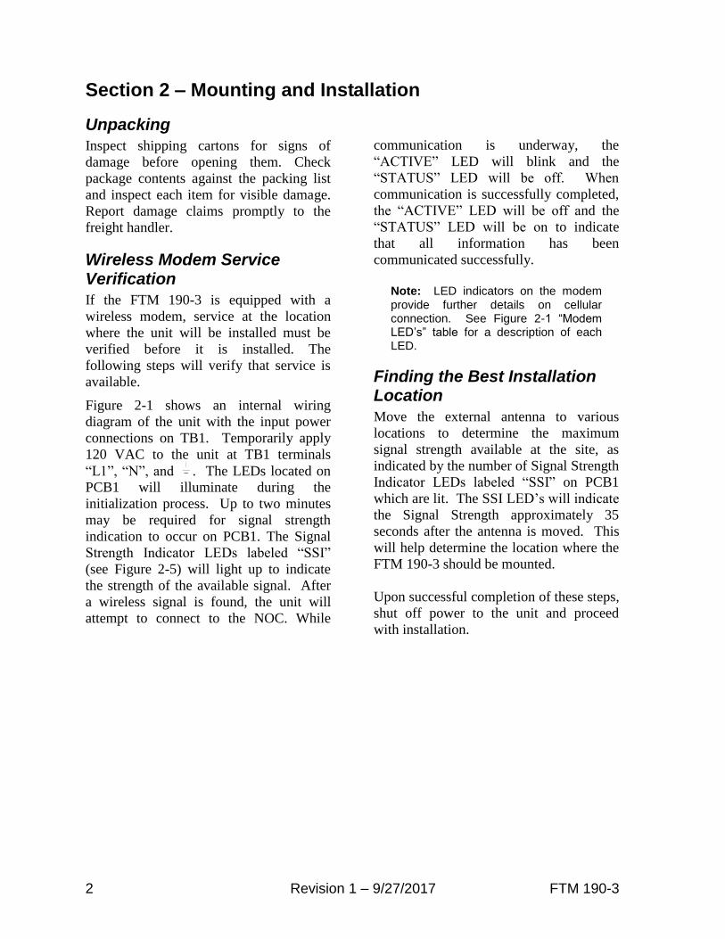
Unpacking
Inspect shipping cartons for signs of
damage before opening them. Check
package contents against the packing list
and inspect each item for visible damage.
Report damage claims promptly to the
freight handler.
Wireless Modem Service Verification
If the FTM 190-3 is equipped with a
wireless modem, service at the location
where the unit will be installed must be
verified before it is installed. The
following steps will verify that service is
available.
Figure 2-1 shows an internal wiring
diagram of the unit with the input power
connections on TB1. Temporarily apply
120 VAC to the unit at TB1 terminals
“L1”, “N”, and . The LEDs located on
PCB1 will illuminate during the
initialization process. Up to two minutes
may be required for signal strength
indication to occur on PCB1. The Signal
Strength Indicator LEDs labeled “SSI”
(see Figure 2-5) will light up to indicate
the strength of the available signal. After
a wireless signal is found, the unit will
attempt to connect to the NOC. While
communication is underway, the
“ACTIVE” LED will blink and the
“STATUS” LED will be off. When
communication is successfully completed,
the “ACTIVE” LED will be off and the
“STATUS” LED will be on to indicate
that all information has been
communicated successfully.
Note: LED indicators on the modem provide further details on cellular connection. See Figure 2-1 “Modem LED’s” table for a description of each LED.
Finding the Best Installation Location
Move the external antenna to various
locations to determine the maximum
signal strength available at the site, as
indicated by the number of Signal Strength
Indicator LEDs labeled “SSI” on PCB1
which are lit. The SSI LED’s will indicate
the Signal Strength approximately 35
seconds after the antenna is moved. This
will help determine the location where the
FTM 190-3 should be mounted.
Upon successful completion of these steps,
shut off power to the unit and proceed
with installation.

3 Revision 1 – 9/27/2017 FTM 190-3
OF
F O
N
Flash Technology
Figure 2-1 – FTM 190-3 Internal Wiring

4 Revision 1 – 9/27/2017 FTM 190-3
Installation
WARNING! Read the warning on Page i now.
Disconnect primary power before opening
enclosures.
Recommended Tools
Flash Technology recommends the
following tools for installation and
maintenance:
• Tools for securing mounting hardware
• 1/8” non-flared flat blade screw driver
• #2 Phillips® head screwdriver
• Long-nose pliers
• Wire Strippers
• Digital volt-ohm meter
• Level
• Cable Ties
• Camera (for documentation)
FTM 190-3 Access
The cover is hinged and secured with
latches. Release the latches and swing the
cover open for internal access.
Mounting
The FTM 190-3 enclosure mounting
outline and dimensions are shown in
Figure 2-2. Ensure that adequate space
exists around the equipment for access
during installation, maintenance and
servicing. Mounting hardware is not
provided unless it is ordered as part of an
installation kit.
AC Power Wiring
The AC line connections are made at
“L1”, “N”, and located on TB1 in the
lower left of the unit. Also located on
TB1 is a Metal Oxide Varistor (VR1) and
a fuse (F1). The incorporation of VR1 and
F1 on TB1 provides increased protection
against AC power transients. The F1 fuse
holder also acts as a power disconnect to
the unit. Grasp the fuse holder at the top
and pull down to disconnect power.
Connect 120 VAC power to terminal
block TB1 (L1, N, ) as shown in Figure
2-1.
Note: Leave power turned off until you are ready for activation (see Section 3).
The terminal block uses spring-cage
contacts to provide rugged, trouble-free
connections which are vibration-proof and
gas-tight, thus providing long-term
stability. The conductor contact force is
determined by the spring tension and so is
independent of the user tightening torque
as with screw type terminals.
To install a wire, follow these steps:
1. Strip the insulation, exposing 0.4
inch (10 mm) or more of
conductor.
2. Insert a standard 1/8” width
screwdriver into the rectangular
slot and push. This causes the
spring clip to open.
3. Insert the conductor fully into the
round terminal compartment and
then remove the screwdriver. The
conductor automatically makes
contact.
4. Check that contact is made to
conductor metal and not insulation.

5 Revision 1 – 9/27/2017 FTM 190-3
Figure 2-2 – Enclosure Mounting Footprint
13.32
(338.3)
11.32 (287.5)
0.406 (10.31) DIA HOLE THRU
(TYP OF 4)
3.17
(80.5)
3.94
(100.1)
12.75
(323.9)
8.00 (203.2)
A A A A
B B B B B

6 Revision 1 – 9/27/2017 FTM 190-3
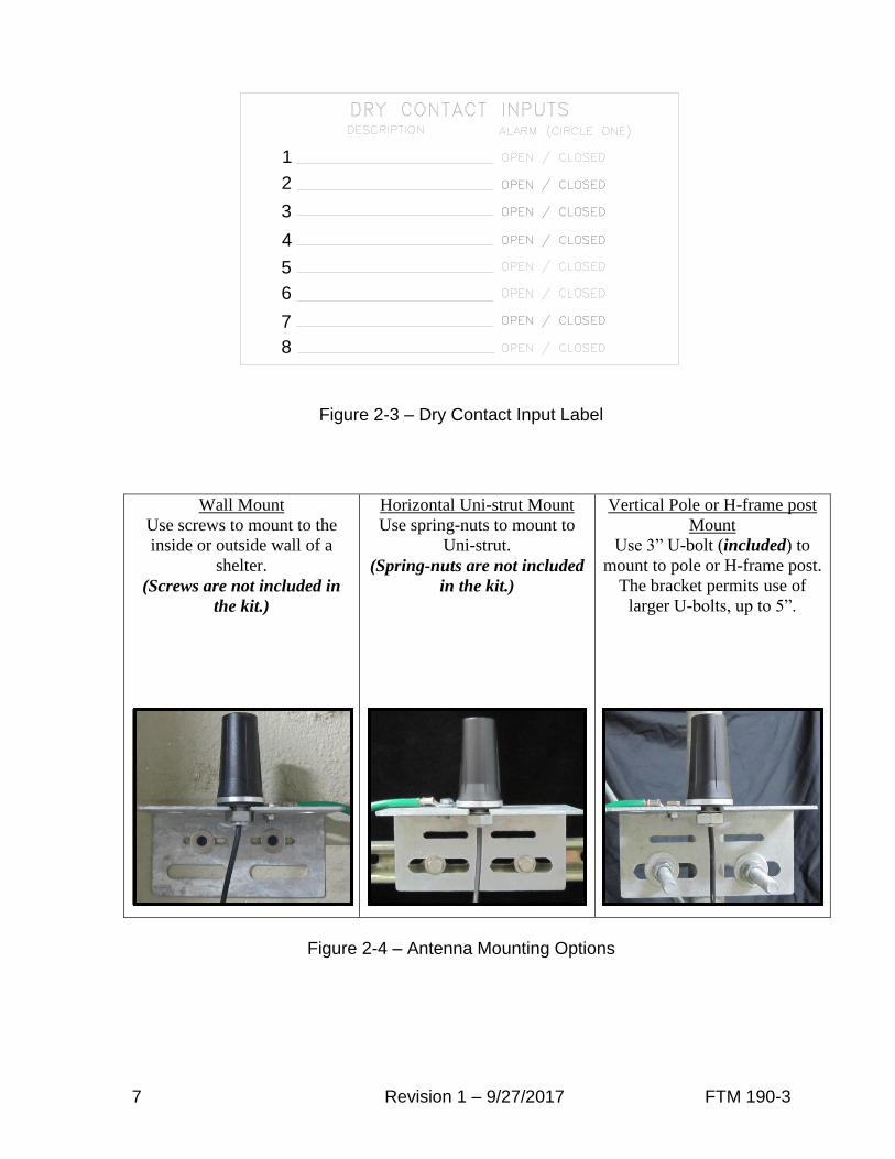
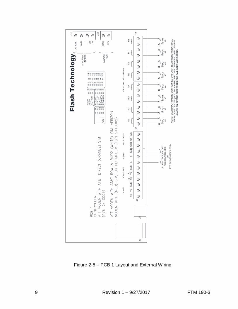
Dry Contact Input Wiring
Connect the equipment to be monitored
via dry contact inputs as shown in Figure
2-5. A label has been provided on the
inside cover of the unit to record each
input, up to eight (8), that is connected.
Figure 2-3 depicts the dry contact input
label.
Note: Each input can be configured by Flash Technology’s National Operations Center (NOC) to alarm on either open or closed status. Alarm on open is preferred for fail safe monitoring.
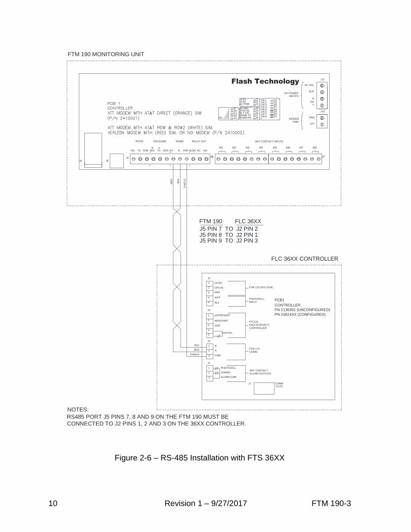
RS-485 Wiring
Connect the Flash Technology FLC
Controller or FTB 3XX medium intensity
strobe system (29038XX PCB required) to
be monitored via RS-485 as shown in
Figures 2-6 and 2-7. Figure 2-5 shows the
layout of PCB1 located in the FTM 190-3.
Antenna Mounting Bracket
The Flash Technology Antenna
Universal Mounting Bracket Kit (PN
1905355) is supplied with units equipped
with a wireless modem. As seen in Figure
2-4, it accommodates the body mount style
antenna and provides multiple mounting
options (wall, Uni-strut, or pole)
permitting antenna installation in the
optimum location for best signal strength
and reliable communication.
Important: The antenna bracket must be
grounded with a minimum AWG 14
Ground wire to the site Grounding System.
Observe proper Grounding procedures.
The FTM 190-3 is shipped with the
antenna preinstalled and the antenna
cable’s SMA connector torqued to
specification onto the modem antenna
connector for optimal performance. Do
not remove or disconnect unless replacing
the modem or antenna.
To install the bulkhead mount style
antenna, loosen the antenna mounting nut
and washer and slide the antenna mount
through the bracket’s center hole
slot. Tighten the hardware.
Important! For best communication performance and to minimize potential for surge damage to the modem radio module, it is very important that the supplied antenna mounting bracket be used for mounting the antenna and that the bracket be grounded with a minimum 14 AWG Ground wire connected to the site Grounding System. Also, if any excess antenna cable is coiled up, the coil diameter must not be less than 18 inches.
Grounding
To provide increased immunity from
lightning damage to the FTM 190-3, it is
essential that the Ground Lug located in
the lower left corner of the baseplate
(Figure 2-1) be properly connected by a
No. 2 AWG conductor to the site
Grounding System. Observe proper
grounding procedures.
7 Revision 1 – 9/27/2017 FTM 190-3
2
3
4
5
6
7
8
1
Figure 2-3 – Dry Contact Input Label
Wall Mount
Use screws to mount to the
inside or outside wall of a
shelter.
(Screws are not included in
the kit.)
Horizontal Uni-strut Mount
Use spring-nuts to mount to
Uni-strut.
(Spring-nuts are not included
in the kit.)
Vertical Pole or H-frame post
Mount
Use 3” U-bolt (included) to
mount to pole or H-frame post.
The bracket permits use of
larger U-bolts, up to 5”.
Figure 2-4 – Antenna Mounting Options
8 Revision 1 – 9/27/2017 FTM 190-3
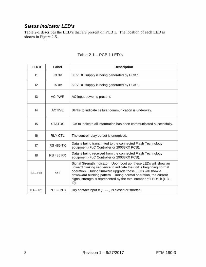
Status Indicator LED’s
Table 2-1 describes the LED’s that are present on PCB 1. The location of each LED is
shown in Figure 2-5.
Table 2-1 – PCB 1 LED’s
LED # Label Description
I1 +3.3V 3.3V DC supply is being generated by PCB 1.
I2 +5.0V 5.0V DC supply is being generated by PCB 1.
I3 AC PWR AC input power is present.
I4 ACTIVE Blinks to indicate cellular communication is underway.
I5 STATUS On to indicate all information has been communicated successfully.
I6 RLY CTL The control relay output is energized.
I7 RS 485 TX Data is being transmitted to the connected Flash Technology equipment (FLC Controller or 29038XX PCB).
I8 RS 485 RX Data is being received from the connected Flash Technology equipment (FLC Controller or 29038XX PCB).
I9 – I13 SSI
Signal Strength Indicator. Upon boot up, these LEDs will show an upward blinking sequence to indicate the unit is beginning normal operation. During firmware upgrade these LEDs will show a downward blinking pattern. During normal operation, the current signal strength is represented by the total number of LEDs lit (I13 – I9).
I14 – I21 IN 1 – IN 8 Dry contact input # (1 – 8) is closed or shorted.
9 Revision 1 – 9/27/2017 FTM 190-3
DC
AU
X
AC
FA
IL
J11
DC
PO
WE
RIN
PU
TS
MO
DE
M
PW
R
J10
12V
GN
D
Fla
sh
T
ec
hnology
J8
J9
I9 I10
I11
I12
I13
SS
I
I4 I5 I6 I7 I8
AC
TIV
ES
TA
TU
SR
LY
CT
LR
S48
5 T
XR
S48
5 R
X
I1 I2 I3
+3.3
V+
5.0
VA
C P
WR
I14
I15
I16
I17
IN 1
IN 2
IN 3
IN 4
I18
I19
IN 5
IN 6
IN 7
IN 8
I20
I21
+ --
RX
TX
GN
DB
AA
BG
ND
NC
NO
CO
M
DR
Y C
ON
TA
CT
IN
PU
TS
RE
LA
Y O
UT
RS
485
RS
232
/485
RS
232
J5
J6
J7
IN1
IN2
IN3
IN4
IN5
IN6
IN7
IN8
RX
TX
GN
D
INP
UT
#1
INP
UT
#2
INP
UT
#3
INP
UT
#4
INP
UT
#5
INP
UT
#6
INP
UT
#7
INP
UT
#8
FLA
SH
TE
CH
NO
LO
GY
FLC
CO
NT
RO
LLE
R
OR
FT
B 3
XX
(29
03
8X
X P
CB
)N
OT
E: E
AC
H IN
PU
T C
AN
BE
CO
NF
IGU
RE
D B
Y F
LA
SH
TE
CH
NO
LO
GY
'S N
AT
ION
AL
OP
ER
AT
ION
S C
EN
TE
R (
NO
C)
TO
AL
AR
M O
N E
ITH
ER
OP
EN
OR
CL
OS
ED
ST
AT
US
.
AL
AR
M O
N O
PE
N IS
PR
EF
ER
RE
D F
OR
FA
IL S
AF
E M
ON
ITO
RIN
G.
Figure 2-5 – PCB 1 Layout and External Wiring
10 Revision 1 – 9/27/2017 FTM 190-3
FTM 190 MONITORING UNIT
J5 PIN 7 TO J2 PIN 2J5 PIN 8 TO J2 PIN 1J5 PIN 9 TO J2 PIN 3
FTM 190 FLC 36XX
DC
AC FAIL
J11
DC POWERINPUTS
MODEM
PWR
J10
12V
GND
J8J9
I9I10I11I12I13SSI
I4I5I6I7I8
ACTIVESTATUSRLY CTLRS485 TXRS485 RX
I1I2I3
+3.3V+5.0VAC PWR
I14I15I16I17
IN 1IN 2IN 3IN 4
I18I19
IN 5IN 6IN 7IN 8
I20I21
+
--
RX TX GNDB A
A B GND NC NOCOM
DRY CONTACT INPUTSRELAY OUTRS485RS232/485RS232
J5 J6 J7
IN1 IN2 IN3 IN4 IN5 IN6 IN7 IN8
RX TX GND
BLK
RE
D
SH
IELD
3
2
4
5
J3
2
3
4
J2
5
J1
2
3
2
3
J4
1
1
1BLK
RED
SHIELD
1
PHOTOCELL
INPUT
CONTROLLER
PN 2136301 (UNCONFIGURED)
PN 23624XX (CONFIGURED)
DRY CONTACT
ALARM OUTPUTSPOWER
ALARM COM
PHOTOCELL
J7 COMM
TO PC
FTC121
HIGH INTENSITY
CONTROLLER
FTW 174
COMM
AOLFAIL
121PRESENT
BLK
REDSTART
B
GND
A
COM
PCB1
FLC 36XX CONTROLLER
FTW 170 GPS SYNC
12VDC
GND
GPS IN
WHT
CONNECTED TO J2 PINS 1, 2 AND 3 ON THE 36XX CONTROLLER.
RS485 PORT J5 PINS 7, 8 AND 9 ON THE FTM 190 MUST BE
NOTES:
AUX
Flash Technology
Figure 2-6 – RS-485 Installation with FTS 36XX

11 Revision 1 – 9/27/2017 FTM 190-3
FT
M 1
90
MO
NIT
OR
ING
UN
IT
J5 P
IN 7
T
O J8 P
IN 2
J5 P
IN 8
T
O J8 P
IN 1
J5 P
IN 9
T
O J8 P
IN 3
FT
M 1
90
2
9038X
X P
CB
DC
AC
FA
IL
J1
1
DC
PO
WE
R
INP
UT
S
MO
DE
M
PW
R
J1
0
12
V
GN
D
J8
J9
I9 I10
I11
I12
I13
SS
I
I4 I5 I6 I7 I8
AC
TIV
ES
TA
TU
SR
LY
CT
LR
S4
85
TX
RS
48
5 R
X
I1 I2 I3
+3
.3V
+5
.0V
AC
PW
R
I14
I15
I16
I17
IN 1
IN 2
IN 3
IN 4
I18
I19
IN 5
IN 6
IN 7
IN 8
I20
I21
+ --
RX
TX
GN
DB
AA
BG
ND
NC
NO
CO
M
J5
J6
J7
IN1
IN2
IN3
IN4
IN5
IN6
IN7
IN8
RX
TX
GN
D
BLK
RED
SHIELD
CO
NN
EC
TE
D T
O J
8 P
INS
1, 2 A
ND
3 O
N T
HE
9038 P
CB
.
RS
485 P
OR
T J
5 P
INS
7, 8 A
ND
9 O
N T
HE
FT
M 1
90 M
US
T B
E
NO
TE
S:
2 1J8 3J7
J16
J6
J53 5 641
J4 2
J3
J2
J1
J11
J13
J9
OP
TIO
NA
L M
OD
EM
PC
B5
RS
48
5 C
OM
RS
48
5 B
RS
48
5 A
CA
RD
12
34
56
78
TIM
ING
AN
D T
RIG
GE
R
PC
B1
29038X
X
ME
DIU
M IN
TE
NS
ITY
ST
RO
BE
SY
ST
EM
(29038X
X P
CB
)
SH
IEL
D
BL
K
RE
D
TH
E R
S 4
85 A
DD
RE
SS
(O
PT
ION
SW
ITC
HE
S 2
-4)
MU
ST
BE
SE
LE
CT
ED
ON
TH
E 2
9038 P
CB
.
OF
F
ON2
OF
F
ON
OF
F
OF
F
3
ON
OF
F
OF
F
4
OF
F
OF
F
ON
OF
F
OF
F
ON
DIS
AB
LE
D
21 3 4
AD
DR
ES
S
RS
48
5 A
DD
RE
SS
OFF
3 5 641 23 5 641 2 3 5 641 2 7 8
1
3
2
1
2
3
5
6
4
1
2
7
8
1
2
1
2
1
2
1
2
1
3
2
1
3
2
1
3
2
1
3
2
31 231 231 2
AU
X
DR
Y C
ON
TA
CT
IN
PU
TS
RE
LA
Y O
UT
RS
485
RS
23
2/4
85
RS
232
Fla
sh
T
ec
hn
ology
Figure 2-7 – RS-485 Installation with FTB 3XX (29038XX PCB)

12 Revision 1 – 9/27/2017 FTM 190-3
FTM 190 MONITORING UNIT
J5 PIN 7 TO J6 PIN 1J5 PIN 8 TO J6 PIN 2J5 PIN 9 TO J6 PIN 3
FTM 190 2151500 PCB
DC
AC FAIL
J11
DC POWERINPUTS
MODEM
PWR
J10
12V
GND
J8J9
I9I10I11I12I13SSI
I4I5I6I7I8
ACTIVESTATUSRLY CTLRS485 TXRS485 RX
I1I2I3
+3.3V+5.0VAC PWR
I14I15I16I17
IN 1IN 2IN 3IN 4
I18I19
IN 5IN 6IN 7IN 8
I20I21
+
--
RX TX GNDB A
A B GND NC NOCOM
J5 J6 J7
IN1 IN2 IN3 IN4 IN5 IN6 IN7 IN8
RX TX GND
BLK
RE
D
SH
IELD
CONNECTED TO J6 PINS 1, 2 AND 3 ON THE 371 SMART AC PCB.
RS485 PORT J5 PINS 7, 8 AND 9 ON THE FTM 190 MUST BE
NOTES:
FTS 371 SMART AC FTC (2151500 PCB)
AUX
DRY CONTACT INPUTSRELAY OUTRS485RS232/485RS232
Flash Technology
PCB1
P/N 2151500
J1 J2 J3 J4 J5
J6
J9
J10
A B CO
M
J7
CONFIGURATION
GPS
(OPTIONAL)
USB
J8
ALARMS
SHIELD
BLK
RED
INSURE THE RS-485 ROTARY SWITCH IS IN POSITION 0 ON THE
371 SMART AC PCB.
Figure 2-8 – RS-485 Installation with FTS 371
13 Revision 1 – 9/27/2017 FTM 190-3
Section 3 – Activation
Monitoring
Once installation is completed, follow the
procedure below to activate service and
begin monitoring:
1. Please be prepared to provide the
following information:
The wireless number for this unit. The
label is located on the inside front
cover.
Your name, contact number and
company.
If monitoring an FCC registered tower
site, the site number and FCC number.
Descriptions of the items being
monitored by each input.
2. Re-apply power to the equipment and
observe the “SSI”, “Active” and
“Status” LED’s.
Note: Refer to Figure 2-5 for LED locations and Table 2-1 to LED descriptions.
3. When power up initialization is
complete, the SSI LED’s will blink
one at a time in an upward pattern
followed by all the SSI LED’s blinking
once together. This indicates normal
firmware operation is starting.
4. Up to two minutes may be required
after power-up for signal strength
indication to occur on PCB1. The
Signal Strength Indicator LEDs
labeled “SSI” on PCB1 will light up to
indicate the strength of the available
signal. While communication is
underway, the “Active” LED will
blink and the “Status” LED will be off.
When communication is successfully
completed, the “ACTIVE” LED will
be off and the “STATUS” LED will be
on to indicate that all information has
been communicated successfully.
5. Secure the external antenna on the
Antenna Mounting Bracket in a
location which provides maximum
signal strength as indicated by the
number of “SSI” LEDs lit (I13 – I9).
6. Connect the red wire to + (Positive)
and the black wire to – (Negative) on
the battery as shown in Figure 2-1.
7. Call 1-800-821-5825 to initiate
monitoring while on-site. The NOC
technician will request several tests to
be performed to verify correct
installation and operation of the
system.
Note: Once the unit is powered and communication is established, it will automatically send a message to the NOC to initiate service and billing will begin.
14 Revision 1 – 9/27/2017 FTM 190-3
Section 4 – Web Interface
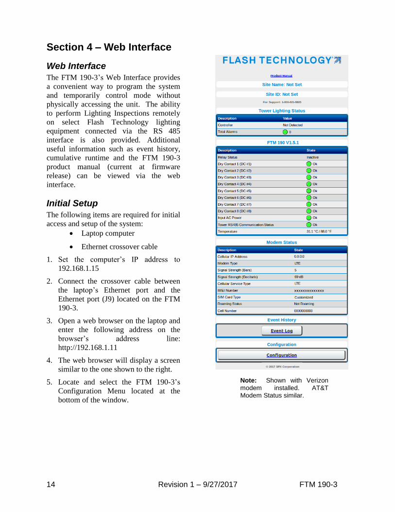
Web Interface
The FTM 190-3’s Web Interface provides
a convenient way to program the system
and temporarily control mode without
physically accessing the unit. The ability
to perform Lighting Inspections remotely
on select Flash Technology lighting
equipment connected via the RS 485
interface is also provided. Additional
useful information such as event history,
cumulative runtime and the FTM 190-3
product manual (current at firmware
release) can be viewed via the web
interface.
Initial Setup
The following items are required for initial
access and setup of the system:
Laptop computer
Ethernet crossover cable
1. Set the computer’s IP address to
192.168.1.15
2. Connect the crossover cable between
the laptop’s Ethernet port and the
Ethernet port (J9) located on the FTM
190-3.
3. Open a web browser on the laptop and
enter the following address on the
browser’s address line:
http://192.168.1.11
4. The web browser will display a screen
similar to the one shown to the right.
5. Locate and select the FTM 190-3’s
Configuration Menu located at the
bottom of the window.
Note: Shown with Verizon modem installed. AT&T Modem Status similar.

15 Revision 1 – 9/27/2017 FTM 190-3
Configuration Menu
The Configuration menu provides access
to all of the FTM 190-3’s programmable
settings. The menu is divided into the
following four subsections: Device,
Monitoring, Network and SNMP Labels.
Each menu section is discussed in the
following subheadings.
Device
The Device Configuration menu, shown to
the right, provides access to configure the
dry contact inputs and the relay output. It
also allows RS 485 communication and
input power monitoring to be enabled or
disabled. The following subheadings
provide detailed information regarding
configuration of each option in the Device
Configuration Menu.
Note: Once configuration is completed, any changes must be saved by pressing the “Commit Settings” button.

16 Revision 1 – 9/27/2017 FTM 190-3
Relay Status
The FTM 190-3 provides one relay output
for control of an external device. The state
of the relay output is controlled by the
configuration menu.
Note: Relay contacts rated at 5A 250V AC. The connected load must not exceed this limit.
Dry Contact Input Configuration
The dry contact configuration menu is
divided into three sections. The first
section allows the alarm state of the
contact to be selected.
Note: To ensure proper alarm monitoring, Flash Technology recommends monitoring contacts that are open in an alarm condition (NC).
The second section allows each dry
contact input to be enabled or disabled.
The third section allows an optional noise
filter to be applied to the contact
monitoring firmware to prevent chattering
alarms. A time delay is added to the
restore logic to prevent alarms from
toggling too frequently on sensitive inputs.
Note: Noise filtering only works with dry contacts configured as “NC”.
The noise filters can be temporarily
disabled when conducting lighting
inspections or repairs.
RS 485 Alarm Configuration
If connected, RS 485 communication is
automatically detected and configured.
The RS 485 communication alarm is not
automatically enabled. Enable the alarm if
a device utilizing RS 485 communications
is connected at J5 terminals 7-9.
Typically, the RS 485 alarm is disabled if
dry contact only monitoring is utilized.
Note: Currently, only Flash Technology FTB 3XX Medium Intensity Strobes (29038xx PCB), FTS 36XX systems and FTS 371 Smart systems may be connected via RS 485. See “Tower Menu” for additional information.
Input Power Alarm Configuration
The Input AC Power alarm monitors the
AC power input to the FTM 190-3.
Enable the alarm if notification of AC
power failure is desired.
Commit Settings
Once programming is complete, any
changes must be saved by pressing the
“Commit Settings” button. Press “Cancel”
to discard changes. Press the “Home”
button to return to the main menu.
17 Revision 1 – 9/27/2017 FTM 190-3
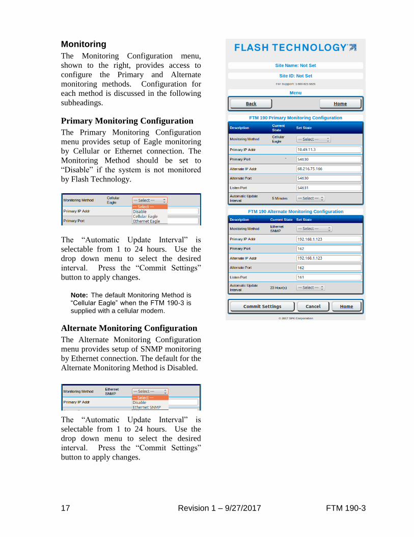
Monitoring
The Monitoring Configuration menu,
shown to the right, provides access to
configure the Primary and Alternate
monitoring methods. Configuration for
each method is discussed in the following
subheadings.
Primary Monitoring Configuration
The Primary Monitoring Configuration
menu provides setup of Eagle monitoring
by Cellular or Ethernet connection. The
Monitoring Method should be set to
“Disable” if the system is not monitored
by Flash Technology.
The “Automatic Update Interval” is
selectable from 1 to 24 hours. Use the
drop down menu to select the desired
interval. Press the “Commit Settings”
button to apply changes.
Note: The default Monitoring Method is “Cellular Eagle” when the FTM 190-3 is supplied with a cellular modem.
Alternate Monitoring Configuration
The Alternate Monitoring Configuration
menu provides setup of SNMP monitoring
by Ethernet connection. The default for the
Alternate Monitoring Method is Disabled.
The “Automatic Update Interval” is
selectable from 1 to 24 hours. Use the
drop down menu to select the desired
interval. Press the “Commit Settings”
button to apply changes.
18 Revision 1 – 9/27/2017 FTM 190-3
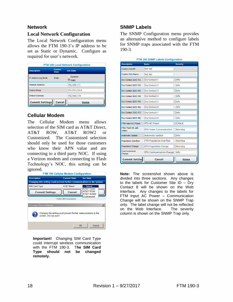
Network
Local Network Configuration
The Local Network Configuration menu
allows the FTM 190-3’s IP address to be
set as Static or Dynamic. Configure as
required for user’s network.
Cellular Modem
The Cellular Modem menu allows
selection of the SIM card as AT&T Direct,
AT&T ROW, AT&T ROW2 or
Customized. The Customized selection
should only be used for those customers
who know their APN value and are
connecting to a third party NOC. If using
a Verizon modem and connecting to Flash
Technology’s NOC, this setting can be
ignored.
Important! Changing SIM Card Type could interrupt wireless communication with the FTM 190-3. The SIM Card Type should not be changed remotely.
SNMP Labels
The SNMP Configuration menu provides
an alternative method to configure labels
for SNMP traps associated with the FTM
190-3.
Note: The screenshot shown above is divided into three sections. Any changes to the labels for Customer Site ID – Dry Contact 8 will be shown on the Web Interface. Any changes to the labels for FTM Input AC Power – Communication Change will be shown on the SNMP Trap only. The label change will not be reflected on the Web Interface. The severity column is shown on the SNMP Trap only.

19 Revision 1 – 9/27/2017 FTM 190-3
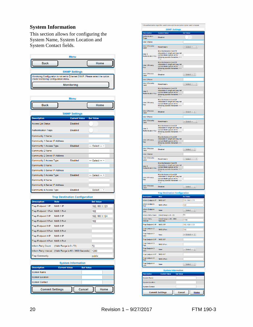
SNMP Settings
This menu allows for configuration of
various settings related to SNMP. In the
System Settings menu, the option to
choose SNMP version V2C or V3 exists.
The settings available on this page will
vary based on that selection.
Access List Status
When enabled, the system will enforce the
configured SNMP access control list. This
setting is disabled by default.
Authentication Traps
When enabled, a trap will be sent for every
unauthorized access attempt. This setting
is disabled by default.
Communities (V2C only)
Up to four access communities may be
configured. For each community a name,
IP address and access type may be
configured. The access type options are
“Disabled”, “Read-Only” and “Read-
Write”.
Users (V3 only)
Up to four users may be configured. Each
user will have the following settings:
User Name
Maximum 20 characters, no spaces
User Security Level
Security level adopted for access.
• Noauthnopriv (No authentication
and encryption. Not
recommended.)
• Authnopriv (authentication but no
encryption)
• Authpriv (authentication and
encryption)
User Access Level
The options are “Disabled”, “Read-
Only” and “Read-Write”.
User Authentication Key
Passcode for authentication. Valid
range is 8 – 20 characters and may
not contain blank spaces or the
following special characters: < > " '
\ / (mandatory if Auth is selected as
part of security level)
User Privacy Key
Passcode for encryption. Valid
range is 8 – 20 characters.
Mandatory if Authpriv security
level is selected.
Trap Destination Configuration
This section allows for setting up to four
trap destination endpoints. The first two
endpoints are the same as those configured
from the Monitoring Configuration
section. Endpoints three and four may
only be viewed and configured from the
SNMP Settings page.
Each endpoint requires an IP address and
port. For V3 only, a User Name will
associate a SNMP V3 user to this
particular trap destination. More than one
user can be associated to same destination
By default a trap requires a confirmation
of receipt before the system stops trying to
send it. The settings related to this may
also be configured in this section. The
default is to send a trap up to 72 times
every 20 minutes (24 hours total duration)
until an acknowledgement has been
received. To disable trap retries, simply
change the retry count to 0.
For SNMP V2C only, the trap community
string may also be modified. The default
value is “public”.
20 Revision 1 – 9/27/2017 FTM 190-3
System Information
This section allows for configuring the
System Name, System Location and
System Contact fields.
21 Revision 1 – 9/27/2017 FTM 190-3
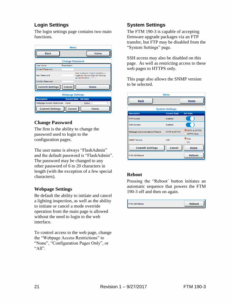
Login Settings
The login settings page contains two main
functions.
Change Password
The first is the ability to change the
password used to login to the
configuration pages.
The user name is always “FlashAdmin”
and the default password is “FlashAdmin”.
The password may be changed to any
other password of 6 to 20 characters in
length (with the exception of a few special
characters).
Webpage Settings
Be default the ability to initiate and cancel
a lighting inspection, as well as the ability
to initiate or cancel a mode override
operation from the main page is allowed
without the need to login to the web
interface.
To control access to the web page, change
the “Webpage Access Restrictions” to
“None”, “Configuration Pages Only”, or
“All”.
System Settings
The FTM 190-3 is capable of accepting
firmware upgrade packages via an FTP
transfer, but FTP may be disabled from the
“System Settings” page.
SSH access may also be disabled on this
page. As well as restricting access to these
web pages to HTTPS only.
This page also allows the SNMP version
to be selected.
Reboot
Pressing the “Reboot´ button initiates an
automatic sequence that powers the FTM
190-3 off and then on again.
22 Revision 1 – 9/27/2017 FTM 190-3
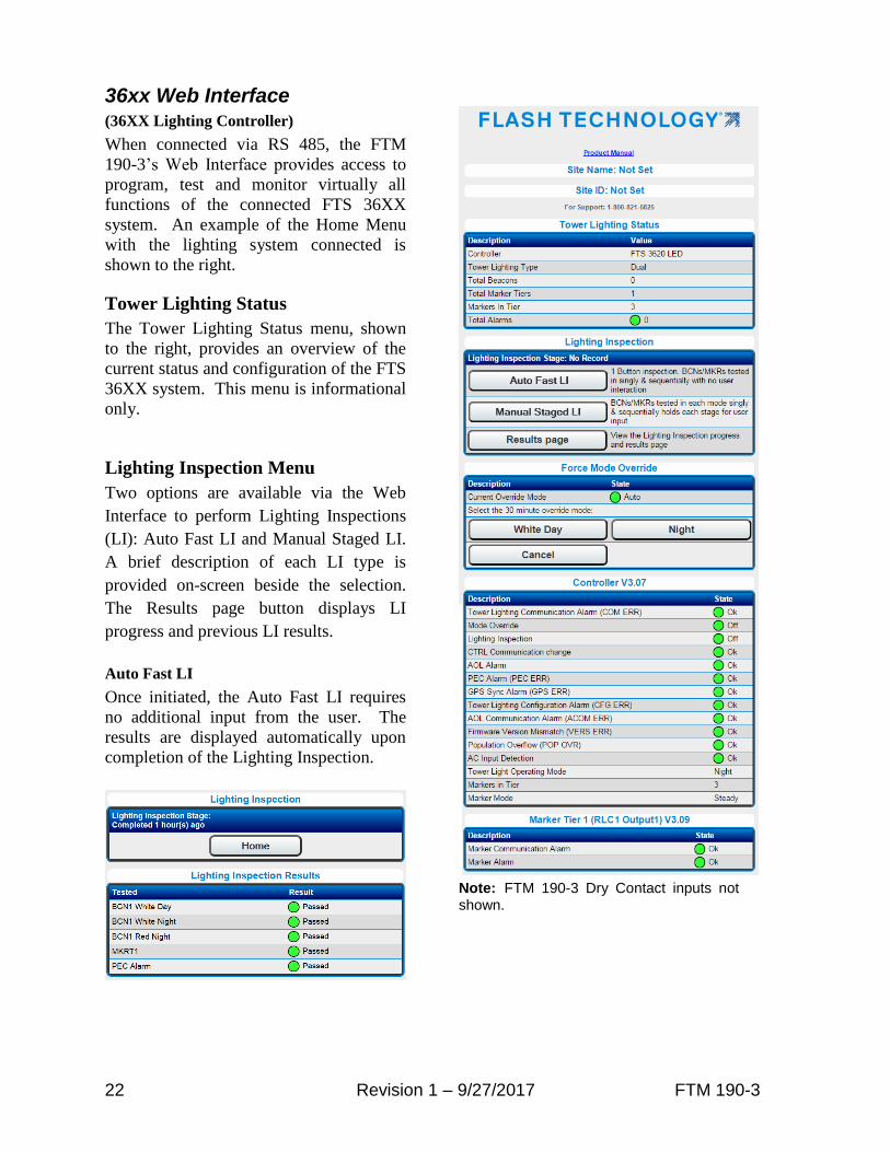
36xx Web Interface (36XX Lighting Controller)
When connected via RS 485, the FTM
190-3’s Web Interface provides access to
program, test and monitor virtually all
functions of the connected FTS 36XX
system. An example of the Home Menu
with the lighting system connected is
shown to the right.
Tower Lighting Status
The Tower Lighting Status menu, shown
to the right, provides an overview of the
current status and configuration of the FTS
36XX system. This menu is informational
only.
Lighting Inspection Menu
Two options are available via the Web
Interface to perform Lighting Inspections
(LI): Auto Fast LI and Manual Staged LI.
A brief description of each LI type is
provided on-screen beside the selection.
The Results page button displays LI
progress and previous LI results.
Auto Fast LI
Once initiated, the Auto Fast LI requires
no additional input from the user. The
results are displayed automatically upon
completion of the Lighting Inspection.
Note: FTM 190-3 Dry Contact inputs not shown.

23 Revision 1 – 9/27/2017 FTM 190-3
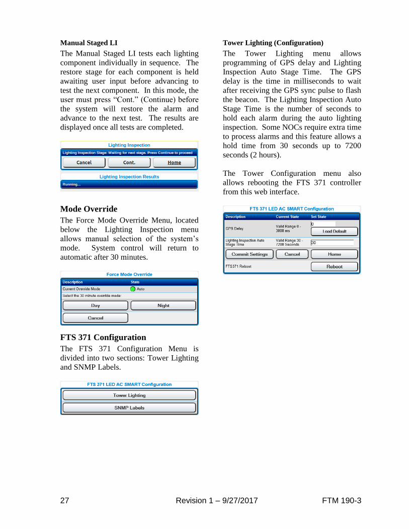
Manual Staged LI
The Manual LI tests each lighting
component individually in sequence. The
restore stage for each component is held
awaiting user input before advancing to
test the next component. In this mode, the
user must press “Cont.” (Continue) before
the system will restore the alarm and
advance to the next test. The results are
displayed once all tests are completed.
Note: The 36xx LED display will show this LI mode as “Manual LI”.
Mode Override
The Force Mode Override Menu, located
below the Lighting Inspection menu
allows manual selection of the system’s
mode. System control will return to
automatic after 30 minutes.
FTS 36XX Configuration
The FTS 36XX Configuration Menu is
divided into two sections: Tower Lighting
and SNMP Labels.
Tower Lighting (Configuration)
The Tower Lighting menu allows
programming of system type, number of
beacons and marker tiers. A drop down
menu is provided for each option. Marker
mode (flashing or steady) is selected by
clicking on the desired setting.
Important! The Tower Configuration must be programmed to match the FAA designated lighting system type for the structure.
The Tower Configuration menu also
allows the photocell alarm (PEC Defeat)
to be enabled or disabled. When enabled,
the system’s 19 hour mode timer is
prevented from generating a photocell
alarm. This feature is particularly useful
in areas that are prone to periods of light
or darkness that would exceed the 19 hour
mode timer. Press the “Commit Settings”
button to apply changes.
Note: The photocell alarm is intended to provide notification of a possible failure in the system. The disarm feature should only be activated if the system is installed in a location prone to conditions previously described. Verify that the photocell is installed and functioning correctly before enabling this option.

24 Revision 1 – 9/27/2017 FTM 190-3
SNMP Labels (Configuration)
The SNMP Labels Configuration menu
allows an alternative method to configure
the labels for SNMP traps associated with
the FTS 36XX.
Note: Any changes to the FTS 36XX labels will be shown on the SNMP Trap only. The label change will not be reflected on the Web Interface.

25 Revision 1 – 9/27/2017 FTM 190-3
PC Web Interface (Medium Intensity Strobe 29038XX PCB)
When connected via RS 485, the FTM
190-3’s Web Interface, shown to the right,
provides access to review the
configuration and current status of the
Flash Technology Medium Intensity
Strobe system (29038XX PCB).
Mode Override
The Force Mode Override Menu allows
manual selection of the system’s mode.
System control will return to automatic
after 30 minutes.
26 Revision 1 – 9/27/2017 FTM 190-3
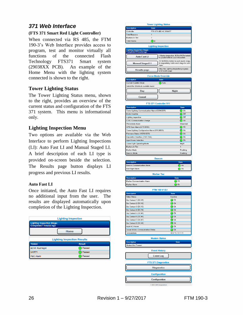
371 Web Interface (FTS 371 Smart Red Light Controller)
When connected via RS 485, the FTM
190-3’s Web Interface provides access to
program, test and monitor virtually all
functions of the connected Flash
Technology FTS371 Smart system
(29038XX PCB). An example of the
Home Menu with the lighting system
connected is shown to the right.
Tower Lighting Status
The Tower Lighting Status menu, shown
to the right, provides an overview of the
current status and configuration of the FTS
371 system. This menu is informational
only.
Lighting Inspection Menu
Two options are available via the Web
Interface to perform Lighting Inspections
(LI): Auto Fast LI and Manual Staged LI.
A brief description of each LI type is
provided on-screen beside the selection.
The Results page button displays LI
progress and previous LI results.
Auto Fast LI
Once initiated, the Auto Fast LI requires
no additional input from the user. The
results are displayed automatically upon
completion of the Lighting Inspection.
27 Revision 1 – 9/27/2017 FTM 190-3
Manual Staged LI
The Manual Staged LI tests each lighting
component individually in sequence. The
restore stage for each component is held
awaiting user input before advancing to
test the next component. In this mode, the
user must press “Cont.” (Continue) before
the system will restore the alarm and
advance to the next test. The results are
displayed once all tests are completed.
Mode Override
The Force Mode Override Menu, located
below the Lighting Inspection menu
allows manual selection of the system’s
mode. System control will return to
automatic after 30 minutes.
FTS 371 Configuration
The FTS 371 Configuration Menu is
divided into two sections: Tower Lighting
and SNMP Labels.
Tower Lighting (Configuration)
The Tower Lighting menu allows
programming of GPS delay and Lighting
Inspection Auto Stage Time. The GPS
delay is the time in milliseconds to wait
after receiving the GPS sync pulse to flash
the beacon. The Lighting Inspection Auto
Stage Time is the number of seconds to
hold each alarm during the auto lighting
inspection. Some NOCs require extra time
to process alarms and this feature allows a
hold time from 30 seconds up to 7200
seconds (2 hours).
The Tower Configuration menu also
allows rebooting the FTS 371 controller
from this web interface.

28 Revision 1 – 9/27/2017 FTM 190-3
SNMP Labels (Configuration)
The SNMP Labels Configuration menu
allows an alternative method to configure
the labels for SNMP traps associated with
the FTS 371.
Note: Any changes to the FTS 371 labels will be shown on the SNMP Trap only. The label change will not be reflected on the Web Interface.
FTS 371 Diagnostics
When connected to a FTS 371 Red Light
Controller, the main menu page will show
an FTS 371 diagnostics button. Clicking
this will show a screen similar to the one
below showing diagnostic status of the
controller to assist in troubleshooting.

29 Revision 1 – 9/27/2017 FTM 190-3
Section 5 – Troubleshooting
Table 5-1 – Troubleshooting – Power
Step Check/Test/Action Action
1.a Is PCB1’s AC PWR LED lit? Yes No
Go to Step 1.g Go to Step 1.b
1.b Is AC power applied to the FTM 190-3? Measure at TB1 terminals L1 & N.
Yes No
Go to Step 1.c Check power source, circuit breaker or disconnect switch and wiring between source and FTM 190-3.
1.c Is AC power present at the output of TB1? Measure at TB1 terminals L1F and N.
Yes No
Go to Step 1.d Remove input power at the source. Replace fuse F1 and VR1.
1.d Is AC input power present on input of PCB2? Measure at L and N on PCB2. See Figure 2-1 for location.
Yes No
Go to Step 1.e Check / repair wiring between TB1 and PCB2.
1.e Is PCB2’s Green “AC” LED lit? See Figure 2-1 for location.
Yes No
Go to Step 1.f Replace PCB2.
1.f Is the AC Fail Input grounded at PCB1? Measure DC Voltage between PCB1 J11 Yellow and Orange wires. Is the voltage zero volts DC?
Yes No
Replace PCB1. Check/repair wiring between PCB2 and PCB1. Replace PCB2
1.g Are both of PCB1’s DC Power LED’s (+3.3V, +5.0V) lit?
Yes No
Go to Step 2.a Go to Step 1.h
1.h Is PCB2’s Red “DC” LED lit? Note: Verify that the input power switch, located on PCB2, is in the “On” position. See Figure 2-1 for LED and switch locations.
Yes No
Go to Step 1.i Go to Step 1.j
1.i Is DC voltage present on PCB1 J11? Measure at J11 DC- and DC+.
Yes No
Replace PCB1 Go to Step 1.j
1.j Is PCB2’s Red “DC” LED lit when output power to PCB1 is disconnected? With the system power off, unplug connector J10 (if installed) and J11 on PCB1. Apply power to the system.
Yes No
Go to Step 1.k Replace PCB2.
1.k Is PCB2’s Red “DC” LED lit when output power to PCB1 reconnected but J10 is not connected? Power the system down and reconnect J11. Connector J10 (if present) should remain disconnected. Power the system on and check the status of the DC LED.
Yes No
Check / repair wiring between J10 and optional modem. Replace modem if necessary. Replace PCB1.
30 Revision 1 – 9/27/2017 FTM 190-3
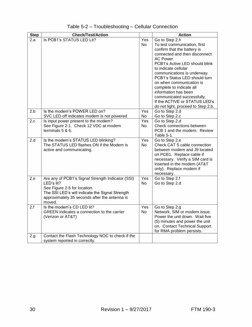
Table 5-2 – Troubleshooting – Cellular Connection
Step Check/Test/Action Action
2.a Is PCB1’s STATUS LED Lit? Yes No
Go to Step 2.h To test communication, first confirm that the battery is connected and then disconnect AC Power. PCB1’s Active LED should blink to indicate cellular communications is underway. PCB1’s Status LED should turn on when communication is complete to indicate all information has been communicated successfully. If the ACTIVE or STATUS LED’s do not light, proceed to Step 2.b.
2.b Is the modem’s POWER LED on? SVC LED off indicates modem is not powered
Yes No
Go to Step 2.d Go to Step 2.c
2.c Is input power present to the modem? See Figure 2-1. Check 12 VDC at modem terminals 5 & 6.
Yes No
Go to Step 2.d Check connections between PCB 1 and the modem. Review Table 5-1.
2.d Is the modem’s STATUS LED blinking? The STATUS LED flashes ON if the Modem is active and communicating.
Yes No
Go to Step 2.e Check CAT 5 cable connection between modem and J9 located on PCB1. Replace cable if necessary. Verify a SIM card is inserted in the modem (AT&T only). Replace modem if necessary.
2.e Are any of PCB1’s Signal Strength Indicator (SSI) LED’s lit? See Figure 2-5 for location. The SSI LED’s will indicate the Signal Strength approximately 35 seconds after the antenna is moved.
Yes No
Go to Step 2.f Go to Step 2.d
2.f Is the modem’s CD LED lit? GREEN indicates a connection to the carrier (Verizon or AT&T)
Yes No
Go to Step 2.g Network, SIM or modem issue. Power the unit down. Wait five (5) minutes and power the unit on. Contact Technical Support for RMA problem persists.
2.g Contact the Flash Technology NOC to check if the system reported in correctly.

31 Revision 1 – 9/27/2017 FTM 190-3
Section 6 – Recommended Spare & Replaceable Parts
Customer Service
Customer Service: (800) 821-5825
Telephone: (615) 261-2000
Facsimile: (615) 261-2600
Shipping Address:
Flash Technology
332 Nichol Mill Lane
Franklin, TN 37067
Ordering Parts
To order spare or replacement parts, contact customer service at 1-800-821-5825.
Important! When removing power from the equipment, ensure that the red wire to the battery is disconnected first. Reconnect battery after work is completed.

32 Revision 1 – 9/27/2017 FTM 190-3
OF
F O
N
NC NO NC NOC C
+
LOW
BATAC
FAIL
DC
AUX
AC FAIL
J11
DC POWER
INPUTS
MODEM
PWR
J10
12V
GND
Flash Technology
J8J9
12
V
PCB2
POWER SUPPLY(P/N 5370500)
(LOCATED UNDER PCB1)
BAT DC
L G N
AC DC
GN
D
I9I10I11I12I13SSI
I4I5I6I7I8
ACTIVESTATUSRLY CTLRS485 TXRS485 RX
I1I2I3
+3.3V+5.0VAC PWR
I14I15I16I17
IN 1IN 2IN 3IN 4
I18I19
IN 5IN 6IN 7IN 8
I20I21
+
--
+
RX TX GNDB A
A B GND NC NOCOM
DRY CONTACT INPUTSRELAY OUTRS485RS232/485RS232
J5 J6 J7
IN1 IN2 IN3 IN4 IN5 IN6 IN7 IN8RX TX GND
-- --
MODEM
ATT (P/N 5905106)
GND
OPTION
INSTALL AREA
PCB3
PROCESSOR
VERIZON (P/N 5905107)
Figure 6-1 – Component Locations

33 Revision 1 – 9/27/2017 FTM 190-3
Table 6-1 – Major Replaceable Parts
Reference Description Part Number
PCB1
CONTROLLER PCB - ATT MODEM WITH AT&T DIRECT (ORANGE) SIM CARD
2410001
CONTROLLER PCB - ATT MODEM WITH AT&T ROW or ROW2 (WHITE) SIM CARD
2410002 CONTROLLER PCB - VERIZON MODEM WITH (RED) SIM CARD
CONTROLLER PCB - NO MODEM
PCB2 POWER SUPPLY (LOCATED UNDER PCB1) 5370500
BATTERY 12V BATTERY 4991875
TB1 TERMINAL BLOCK 1362180
F1 FUSE 3 AMP 3AB (LOCATED ON TB1) 4150218
VR1 VARISTOR 130V (LOCATED ON TB1) 6901079
HARNESS, AC POWER 4370761
Table 6-2 – Optional Items
Reference Description Part Number
MODEM WIRELESS MODEM (ATT) 5905106T
WIRELESS MODEM (VERIZON) 5905107T
ANTENNA BRACKET
KIT ANTENNA MOUNTING BRACKET (INCLUDED WITH OPTIONAL MODEM)
1905355
ANTENNA WIDE BAND BODY MOUNT FOR ATT OR VERIZON (INCLUDED WITH OPTIONAL MODEM)
4905230
HARNESS, MODEM POWER 4370751
CABLE RS-485; SINGLE PAIR, 22 AWG, RED/BLACK 5905302
CABLE DRY CONTACTS; 4 PAIR, 22 AWG, RED/BLACK 5993101
CABLE CAT5 3’ (FT) 4370970
34 Revision 1 – 9/27/2017 FTM 190-3
Appendix A: FTM 190-3 (v1.5) SNMP V2c INFORM TRAPs
The FTM-190-3 supports SNMP V2c INFORM TRAPs to notify SNMP managers of field
events. Any INFORM that is not acknowledged within 20 minutes will be resent every 20
minutes until it is acknowledged; up to 24 hours. SNMP TRAPs do not require
acknowledgement. This document describes the default severities for INFORMs. The severity
setting and name for all INFORMs is configurable via the FTM 190 web interface or SNMP sets.
FTM-190-3 SNMP INFORM TRAPs Default Severities
Critical
INFORMs, whose default severity setting is set to Critical, are those which indicate a NOTAM
worthy event. The set of Critical INFORMs would be the minimum set required to handle to
ensure proper monitoring.
See Table A-1 for a list of Critical INFORMs and their descriptions.
Warning
INFORMs, whose default severity setting is set to Warning, are those which indicate
maintenance is needed on a component of the lighting system, but would not necessarily require
a NOTAM. In some situations these INFORMs may be as important as the Critical events and in
others they may not.
See Table A-2 for a list of Warning INFORMs and their descriptions.
Info
INFORMs, whose default severity setting is set to ‘Info’, do not indicate NOTAM worthy
events; although some of them may accompany the Critical INFORMs as additional diagnostic
information.
See Table A-3 for a list of Informational INFORMs and their descriptions.

35 Revision 1 – 9/27/2017 FTM 190-3
Table A-1 – FTM 190-3 Critical INFORMs
Name Default Severity
Description OID
ftmInputACPowerStatus Critical
System Power Failure Alarm (POWER FAIL): FTM 190 power failure alarm. FTM 190 need to operate on battery backup to provide alarm INFORM.
.1.3.6.1.4.1.9882.3.2.1.1.9
Table A-2 – FTM 190-3 Warning INFORMs
Name Default Severity
Description OID
ftmTowerRS485Status Warning FTM 190 tower RS 485 Communication alarm. .1.3.6.1.4.1.9882.3.2.1.1.10
populationOverflow Warning Population Overflow Alarm: The FTM 190 has detected more devices on its tower RS485 port than it can support
.1.3.6.1.4.1.9882.3.2.1.1.12
populationChange Warning Population Change:FTM 190 has detected a change in the number of units connected to it via RS485.
.1.3.6.1.4.1.9882.3.2.1.1.13
Table A-3 – FTM 190-3 Informational INFORMs
Name Default Severity
Description OID
automaticUpdate Info Automatic Update: A notification which is sent based on a configured time interval.
.1.3.6.1.4.1.9882.3.2.1.1.11
communicationChange Info Communication Change: FTM 190 has lost or regained communication with the connected devices.
.1.3.6.1.4.1.9882.3.2.1.1.14
dryContactStatusx Info Dry Contacts: Dry contact status OK/ALARM. 8 total
.1.3.6.1.4.1.9882.3.2.1.1.1 (to) .1.3.6.1.4.1.9882.3.2.1.1.8
Cold Start Info Cold Start: Sent when the SNMP agent starts up. .1.3.6.1.6.3.1.1.5.1
flashTechnologyRoot.0.2 Info flashTechnologyRoot.0.2: Sent just before the SNMP agent is shutdown or restarted.
.1.3.6.1.4.1.9882.0.2

36 Revision 1 – 9/27/2017 FTM 190-3
36xx SNMP INFORM TRAPs Default Severities
Similar to the FTM 190-3 severities, Tables A-4, A-5 and A-6 show the 36xx traps and their
descriptions.
Table A-4 – 36xx Critical INFORMs
Name Default Severity
Description OID
aolAlarmNotify Critical The controller interface board is having problems communicating to a beacon that is declared as AOL
.1.3.6.1.4.1.9882.3.2.1.2.3
fwVersionMismatchAlarmNotify Critical
The controller interface board has detected an earlier firmware PC interface board that doesn't know what catenary is or an earlier RLC output board that doesn't know what flashing markers is
.1.3.6.1.4.1.9882.3.2.1.2.4
aolCommAlarmNotify Critical The display board has detected a comm failure to a beacon that is configured as a top AOL beacon
.1.3.6.1.4.1.9882.3.2.1.2.5
photocellAlarmNotify Critical
The system has not changed modes for 19+ hours. This indicates the resistive photocell or the associated circuitry in the controller interface board is not operating properly
.1.3.6.1.4.1.9882.3.2.1.2.7
towerLightingCommunicationAlarmNotify Critical The display board has a general communication alarm - it cannot talk to 1 or more devices
.1.3.6.1.4.1.9882.3.2.1.2.8
populationOverflowcontrollerNotify Critical The display board has detected more devices on its tower RS485 port than it can support
.1.3.6.1.4.1.9882.3.2.1.2.12
towerConfigAlarmNotify Critical
The display board has detected more devices on its tower RS485 port than it is currently configured for (example: it finds 3 PCs but is only configured for 2 bcns)
.1.3.6.1.4.1.9882.3.2.1.2.10
whiteDayAlarmNotify Critical There is a white day alarm in the specified power converter
.1.3.6.1.4.1.9882.3.2.1.3.2
NightAlarmNotify Critical There is a red or white night alarm in the specified power converter
.1.3.6.1.4.1.9882.3.2.1.3.4
pcAOLAlarmNotify Critical The specified power converter in alarm is a top AOL beacon (irrelevant on white only towers)
.1.3.6.1.4.1.9882.3.2.1.3.5
pcPCB22ControlAlarmNotify Critical
The PC PCB2 board is reporting a flashing error. Or the PC PCB2 filter board is operating in a mode that is not what the PCB1 interface board is commanding. Likely J04 interface issue.
.1.3.6.1.4.1.9882.3.2.1.3.7
pcTowerCommunicationAlarmNotify Critical The controller is unable to communicate with the beacon.
.1.3.6.1.4.1.9882.3.2.1.3.1
beaconRedNightAlarmNotify Critical
The RLC output board is not detecting enough current draw for a beacon in good operation. Problem with beacon hardware or RLC current detection hardware
.1.3.6.1.4.1.9882.3.2.1.5.1
rlcCommunicationAlarm Critical Communications have been lost with sensing the RLC ouput board responsible for sensing the beacon's current draw.
.1.3.6.1.4.1.9882.3.2.1.4.1
acInputDetectionAlarmNotify Critical
The display board cannot detect the input AC line voltage or frequency (and therefore assumes that 120V AC power is present). This can possibly affect accurate red light alarms (red beacons and markers) as LEDs draw different currents for 120/230/240 Volts.
.1.3.6.1.4.1.9882.3.2.1.2.9
pcPCB2AlarmNotify Critical PC Filter board Alarm. .1.3.6.1.4.1.9882.3.2.1.3.8
37 Revision 1 – 9/27/2017 FTM 190-3
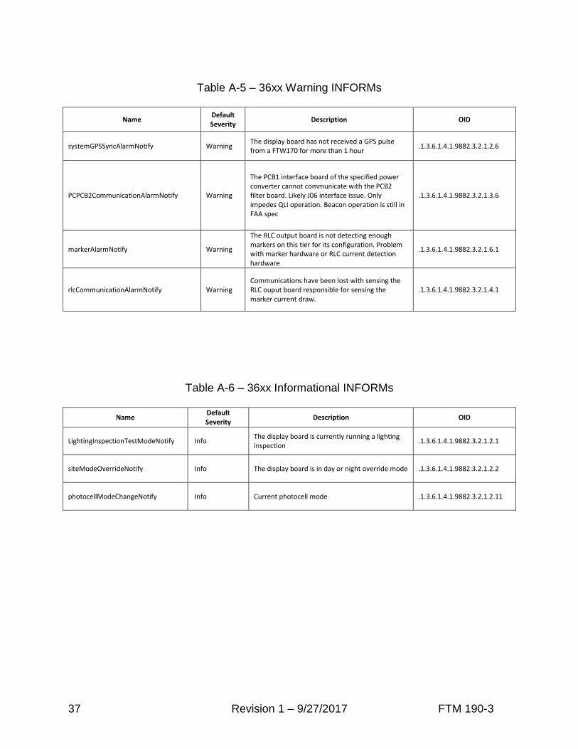
Table A-5 – 36xx Warning INFORMs
Name Default Severity
Description OID
systemGPSSyncAlarmNotify Warning The display board has not received a GPS pulse from a FTW170 for more than 1 hour
.1.3.6.1.4.1.9882.3.2.1.2.6
PCPCB2CommunicationAlarmNotify Warning
The PCB1 interface board of the specified power converter cannot communicate with the PCB2 filter board. Likely J06 interface issue. Only impedes QLI operation. Beacon operation is still in FAA spec
.1.3.6.1.4.1.9882.3.2.1.3.6
markerAlarmNotify Warning
The RLC output board is not detecting enough markers on this tier for its configuration. Problem with marker hardware or RLC current detection hardware
.1.3.6.1.4.1.9882.3.2.1.6.1
rlcCommunicationAlarmNotify Warning Communications have been lost with sensing the RLC ouput board responsible for sensing the marker current draw.
.1.3.6.1.4.1.9882.3.2.1.4.1
Table A-6 – 36xx Informational INFORMs
Name Default Severity
Description OID
LightingInspectionTestModeNotify Info The display board is currently running a lighting inspection
.1.3.6.1.4.1.9882.3.2.1.2.1
siteModeOverrideNotify Info The display board is in day or night override mode .1.3.6.1.4.1.9882.3.2.1.2.2
photocellModeChangeNotify Info Current photocell mode .1.3.6.1.4.1.9882.3.2.1.2.11

38 Revision 1 – 9/27/2017 FTM 190-3
FTS 371 SNMP INFORM TRAPs Default Severities
Similar to the FTM 190-3 severities, Tables A-7 and A-8 show the FTS 371 traps and their
descriptions.
Table A-7 – FTS 371 Critical INFORMs
Name Default Severity
Description OID
fts371PrimaryFirmwareStatusNotify Critical Alarm indicates the primary tower lighting controller Firmware has failed and the unit is running the failsafe firmware.
.1.3.6.1.4.1.9882.3.2.1.7.3
fts371GPSSyncAlarmNotify Critical Indicates GPS sync failure. No GPS signal has been present for 1 hour or the GPS Antenna Status has faulted
.1.3.6.1.4.1.9882.3.2.1.7.4
fts371PhotodiodeAlarmNotify Critical
The system has not changed modes for 19+ hours. This indicates the photodiode or the associated circuitry in the controller interface board is not operating properly
.1.3.6.1.4.1.9882.3.2.1.7.5
fts371InputPowerDetectionAlarmNotify Critical Indicates a site voltage error. Voltage is either out of supported range or not detected.
.1.3.6.1.4.1.9882.3.2.1.7.6
fts371TowerConfigAlarmNotify Critical Indicates a conflicting configuration in the dipswitch banks. For example – more than 1 flash per minute switch is set.
.1.3.6.1.4.1.9882.3.2.1.7.7
fts371masterSyncAlarmNotify Critical (Slave controllers only) Indicates this slave has not received a master flash mode / sync signal for 10 minutes
.1.3.6.1.4.1.9882.3.2.1.7.9
fts371BeaconAlarmNotify Critical One or more beacons are in alarm. Beacons sensed vs configured indicates number of failed beacons
.1.3.6.1.4.1.9882.3.2.1.7.10
fts371MarkerAlarmNotify Critical One or more markers are in alarm. Markers sensed vs configured indicates number of failed markers
.1.3.6.1.4.1.9882.3.2.1.7.11
Table A-8 – FTS 371 Informational INFORMs
Name Default Severity
Description OID
fts371LightingInspectionTestModeNotify Info Indicates system is currently running a lighting inspection
.1.3.6.1.4.1.9882.3.2.1.7.1
fts371SiteModeOverrideNotify Info Indicates system is in day or night override mode .1.3.6.1.4.1.9882.3.2.1.7.2
fts371PhotodiodeModeChangeNotify Info Indicates a Photodiode mode transition (0: Day, 1: Night)
.1.3.6.1.4.1.9882.3.2.1.7.8

FTW 175-3 Revision 1 – 9/27/2017 39
RMA Policy
If any system or part(s) purchased from Flash Technology need to be returned for any reason
(subject to the warranty policy), please see the current RMA policy available online at:
flashtechnology.com/rma.
To initiate an RMA, call the Flash Technology NOC to receive technical assistance (800-821-
5825 Option 9, M-F, 7 a.m. to 7 p.m. CT).
Emailing a completed RMA request form to [email protected] can also start the process
on sites not requiring detailed troubleshooting. The form can be filled out online at:
http://flashtechnology.com/rma-request-form/.
NOTE: An RMA number must be requested from Flash Technology prior to return of any
product. No returned product will be processed without an RMA number. Failure to follow the
below procedure may result in additional charges and delays. Any product received without an
RMA number is subject to return back to the sender. All RMA numbers are valid for 30 days.