Flare Minimization Plan (FMP)/media/files/compliance-and-enforcement… · Flare Minimization Plan,...
146
Phillips 66 San Francisco Refinery Rodeo, California BAAQMD Plant 16 Flare Minimization Plan (FMP) Non-Confidential version Bay Area Air Quality Management District (BAAQMD) Regulation 12, Rule 12 March 2016, Revision 12
Transcript of Flare Minimization Plan (FMP)/media/files/compliance-and-enforcement… · Flare Minimization Plan,...

Phillips 66
San Francisco Refinery
Rodeo, California
BAAQMD Plant 16
Flare
Minimization
Plan (FMP)
Non-Confidential version
Bay Area Air Quality Management District (BAAQMD) Regulation 12, Rule 12
March 2016, Revision 12

Flare Minimization Plan, BAAQMD 12-12 Phillips 66, San Francisco Refinery BAAQMD Plant 16 March 2016, Rev. 12
1-1
Contents
1.0 Flare Minimization Plan ........................................................................................................................... 1-3
1.1 Safety Statement ............................................................................................................................. 1-3
1.2 Executive Summary ......................................................................................................................... 1-3
1.3 Certification ...................................................................................................................................... 1-6
2.0 Flare System Information ........................................................................................................................ 2-1
2.1 Background Information for Flare Systems .................................................................................... 2-1
2.2 Technical Data – Description of Flaring Systems (401.1) .............................................................. 2-3 2.2.1 Phillips 66, San Francisco Refinery Flare & Fuel Gas Recovery System Overview ....... 2-3 2.2.2 Detailed process flow diagram, PFD (401.1.1) ................................................................. 2-3 2.2.3 Description of Monitoring and Control Equipment (401.1.2) ............................................ 2-4
3.0 Reductions & Planned Reductions ........................................................................................................ 3-1
3.1 Reductions Previously Realized (401.2) ......................................................................................... 3-1
3.2 Planned Reductions (401.3) ............................................................................................................ 3-8
4.0 Prevention Measures (401.4) .................................................................................................................. 4-1
4.1 “Major” Maintenance Activities (401.4.1) ........................................................................................ 4-1 4.1.1 Refinery Maintenance and Turnaround Activities ............................................................. 4-1 4.1.2 Measures to Minimize Flaring During Preplanned Maintenance ..................................... 4-8 4.1.3 Turnaround and Maintenance Flare Minimization Planning Tool .................................. 4-15 4.1.4 Measures to Minimize Flaring During Unplanned Maintenance .................................... 4-15
4.2 Gas Quality/Quantity Issues for Each Flare (401.4.2) .................................................................. 4-16 4.2.1 When Flaring is Likely to Occur ...................................................................................... 4-16 4.2.2 Vent Gas Recovery Systems .......................................................................................... 4-20
4.3 Recurrent failure (401.4.3) ............................................................................................................ 4-26 4.3.1 Reportable Flaring Events Attributable to the Same Process or Equipment Item ........ 4-26 4.3.2 Means to Prevent Recurrent Failure ............................................................................... 4-26
5.0 Other Information Requested by APCO to Assure Compliance (401.5) ........................................... 5-1
5.1 New Equipment Installations (404.2) .............................................................................................. 5-1

Flare Minimization Plan, BAAQMD 12-12 Phillips 66, San Francisco Refinery BAAQMD Plant 16 March 2016, Rev. 12
1-2
Attachments Attachment A San Francisco Refinery Simplified Flare System Overview
Attachment B San Francisco Refinery Detailed Flare Gas System Description
Attachment C San Francisco Refinery Flare System Process Flow Diagram
Attachment D DELETED
Attachment E San Francisco Refinery Unit List
Attachment F Flare Minimization Process Flowchart
Attachment G Typical Flare Gas Recovery System
Attachment H Flaring Event Overview, Recurring Failure Review, and Categorization
Attachment I Storage, Treatment, & Recovery Schematic
Attachment J DELETED – previous Attachment J now included in Attachment H
Attachment K Flare Construction BUSINESS CONFIDENTIAL portion
Attachment L Compressor Capacity & Monitoring Description BUSINESS CONFIDENTIAL portion
Attachment M Fuel Gas System Description BUSINESS CONFIDENTIAL portion
Attachment N Cost Effectiveness Calculation Background Material
Flare Minimization Plan, BAAQMD 12-12 Phillips 66, San Francisco Refinery BAAQMD Plant 16 March 2016, Rev. 12
1-3
0.00
0.10
0.20
0.30
0.40
0.50
0.60
0.70
0.80
0.90
1.00
2009 2010 2011 2012 2013 2014 2015 (to date)
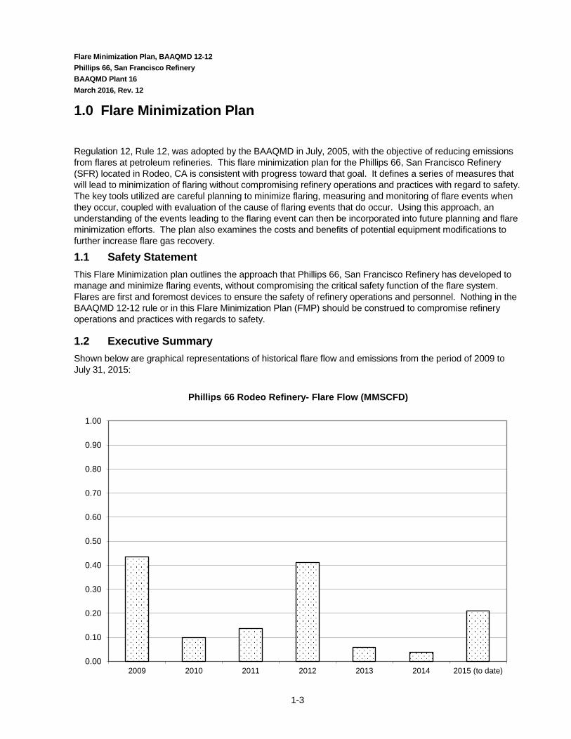
Phillips 66 Rodeo Refinery- Flare Flow (MMSCFD)
1.0 Flare Minimization Plan
Regulation 12, Rule 12, was adopted by the BAAQMD in July, 2005, with the objective of reducing emissions from flares at petroleum refineries. This flare minimization plan for the Phillips 66, San Francisco Refinery (SFR) located in Rodeo, CA is consistent with progress toward that goal. It defines a series of measures that will lead to minimization of flaring without compromising refinery operations and practices with regard to safety. The key tools utilized are careful planning to minimize flaring, measuring and monitoring of flare events when they occur, coupled with evaluation of the cause of flaring events that do occur. Using this approach, an understanding of the events leading to the flaring event can then be incorporated into future planning and flare minimization efforts. The plan also examines the costs and benefits of potential equipment modifications to further increase flare gas recovery.
1.1 Safety Statement This Flare Minimization plan outlines the approach that Phillips 66, San Francisco Refinery has developed to manage and minimize flaring events, without compromising the critical safety function of the flare system. Flares are first and foremost devices to ensure the safety of refinery operations and personnel. Nothing in the BAAQMD 12-12 rule or in this Flare Minimization Plan (FMP) should be construed to compromise refinery operations and practices with regards to safety.
1.2 Executive Summary Shown below are graphical representations of historical flare flow and emissions from the period of 2009 to July 31, 2015:

Flare Minimization Plan, BAAQMD 12-12 Phillips 66, San Francisco Refinery BAAQMD Plant 16 March 2016, Rev. 12
1-4
The Rodeo Refinery installed and has utilized a Flare Gas Recovery Compressor since the mid-70’s. Historic practices emphasized flare minimization. Some of the recent flaring reductions have occurred due to improved monitoring and tracking of flare volumes as well as attributing causes to all flaring as required by BAAQMD 12-11 and 12-12 and internal policies for incident investigation. Other efforts to minimize flare emissions have occurred through communication and improved awareness.
High flare volumes in 2009 and 2012 were due to significant turnaround activities taking place. Key pressure vessels in the flare gas recovery system were removed from service for required 10 year vessel metallurgical inspections in 2009. In 2012 there was a large turnaround which contributed to higher than usual year to date flows. Following the turnaround, a relief valve leaking to the flare was discovered. An engineered solution was developed in order to isolate and provide an alternative relief path. In 2012 there were also a number of periods of fuel gas imbalance in which scrubbed fuel gas was sent to the flare.
In the second half of 2010 the facility experienced a number of flaring events due to the unplanned shutdowns of the 3rd party Hydrogen supplier. Phillips 66 worked closely with the 3rd party Hydrogen supplier to improve reliability at their facility. Work began in 2010 and continued up until mid-2011 when the supplier made significant equipment reliability upgrades during a planned shutdown.
In August 2009 three new, redundant liquid ring Flare Gas Recovery Compressors were installed and put in service. The purpose of the new compressors is to provide additional capacity on a consistent basis and to provide for backup compressor capacity. The new compressors are of a different design than the existing compressor and are designed to handle a wider range of composition and of flare gas. They are also less susceptible to liquid carryover impacts.
0.00
0.10
0.20
0.30
0.40
0.50
0.60
0.70
2009 2010 2011 2012 2013 2014 2015 (to date)
P66 Rodeo Refinery - Flare Emissions (tpd)
CH4 tpd
NMHC tpd
SO2 tpd

Flare Minimization Plan, BAAQMD 12-12 Phillips 66, San Francisco Refinery BAAQMD Plant 16 March 2016, Rev. 12
1-5
Based on a review of small flaring events, the addition of the new Flare Gas Recovery Compressors has reduced the number and volume of brief peak exceedances that previously occurred. This trend was observed since 2009. More importantly, the new compressors were operated on a regular basis while the older compressor was shutdown for major planned maintenance activities. In the past this type of maintenance activity would have resulted in consecutive days of flaring. In these cases the new compressors picked up the flare gas recovery load for a number of days and were effective in reducing flaring volumes.
Another improvement which has occurred is due to improved planning prior to the occurrence of flare activity. Flaring typically occurs during turnarounds when either the gas quality or quantity is not recoverable by the Fuel Gas Recovery Compressor or System. Turnaround planning is conducted to review the periods when flaring may occur. Prior to the turnaround activity, a team discusses these periods in order to determine methods to minimize flaring. In addition, in 2012 a process of further addressing impacted plant systems (e.g. fuel gas, steam, flaring, etc.) was formalized. This high level overview helps to early identify systems which can be optimized prior to a turnaround and in some cases can further reduces flaring.
In early 2011 the manner in which Unit 110 Hydrogen Plant shutdown and startups was changed. This resulted in a significant reduction in the period of flaring which occurs during each of these activities. During 2012 there were a number of periods of flaring associated with Unit 110. Work continued in 2012 and 2013 to further improve procedures to minimize flaring associated with Unit 110 startups and shutdowns. Additionally, although not apparent from the flare trends, there are a number of unit shutdowns that occur each year in which little or no flaring occurs. This is due to past implemented and current practices to reduce flaring.
One of the focus items for flare reduction is fuel gas imbalance. In December 2011 a permit application was submitted to revise permit limits at the Steam Power Plant (SPP). This would allow more refinery fuel gas to be sent to SPP during periods of fuel gas imbalance which typically occur while large turnarounds are taking place. Combustion of purchased natural gas, would be reduced while reducing or eliminating flaring. BAAQMD Permitting is continuing to review this permit application.
Another significant potential project is the Phillips 66 Propane Recovery Project. The purpose of the project is to recover propane and butane from the refinery fuel gas (RFG). Another aspect of the project is to remove a portion of the sulfur compounds from the remaining Refinery Fuel Gas (RFG). From a flaring standpoint, this project is beneficial in reducing overall volume of Refinery Fuel Gas. The propane and butane will be replaced by natural gas provided by PG&E. Because it is relatively easy to reduce the amount of natural gas being imported, the likelihood of flaring due to fuel gas imbalance will be reduced. In addition, by reducing the concentration of sulfur in fuel gas this removes some of the restrictions on where fuel gas can be routed which further helps to minimize and reduce periods of potential fuel gas imbalance. Currently, the Land use Permit is being appealed.
The Rodeo Refinery went 11 months, from July 2013 until June 2014 without a Reportable Flaring Event. This milestone is due to a combination of improved reliability, on-going focus on flare minimization, and light turnaround activity.
In the second half of 2014 through July, 2015, the flaring events were due to equipment malfunction and flaring of scrubbed fuel gas due to fuel gas imbalance related to maintenance work at the Steam Power Plant gas turbines.

Flare Minimization Plan, BAAQMD 12-12 Phillips 66, San Francisco Refinery BAAQMD Plant 16 March 2016, Rev. 12
1-6
1.3 Certification I certify that, based on the information available to me, the flare minimization plan is accurate, true, and complete.
Flare Minimization Plan, BAAQMD 12-12 Phillips 66, San Francisco Refinery BAAQMD Plant 16 March 2016, Rev. 12
2-1
2.0 Flare System Information
2.1 Background Information for Flare Systems
Refineries process crude oil by separating it into a range of components, or fractions, and then rearranging those components to better match the yield of each fraction with market demand. Petroleum fractions include heavy oils and residual materials used to make asphalt or petroleum coke, mid range materials such as diesel (heating oil), jet fuel and gasoline, and lighter products such as butane, propane, and fuel gases.
The San Francisco Refinery is organized into groups of process units, with the general goal of maximizing the production of transportation fuels. Each unit takes in a set of feed streams and produces a set of product streams with the composition changed (or upgraded) as one step toward production of an optimal mix of refined products. Many of these processes operate at elevated temperatures and pressures, and a critical element of safe design is having the capability of releasing excess pressure via relieving devices to the flare header to manage excess materials in a controlled manner. These separation and rearrangement processes also produce and/or consume materials that are gases at atmospheric pressure. As a final step in processing, many units provide treatment to conform to environmental specifications such as reduced sulfur levels.
The refinery is designed and operated so that there will be a balance between the rates of gas production and consumption. Under normal operating conditions, essentially all gases that are produced are routed to the refinery fuel gas system, allowing them to be used for combustion in refinery heaters and boilers. Typical refinery fuel gas systems are configured so that the fuel gas header pressure is maintained by making up natural gas to meet the net fuel requirement. This provides a simple way to keep the system in balance so long as gas needs exceed the volume of gaseous products produced. Additional operational flexibility is typically maintained by having the ability to add butane and having the capability to adjust the rate of fuel gas consumption to a limited extent at the various refinery users (e.g. heaters, boilers, cogeneration units).
A header for collection of vapor streams is included as an essential element of nearly every refinery process unit. These are referred to as “flare headers”, as the ultimate destination for any net excess of gas is a refinery flare. One of the primary functions of the flare header is safety. It provides the process unit with a controlled outlet for any excess vapor flow, making it an essential safety feature of every refinery. The flare header also has connections for equipment depressurization and purging related to maintenance turnaround, startup, and shutdown, as well as pressure relief devices to handle upsets, malfunctions, and emergency releases.
Knockout drums are in place for separation of entrained liquid. This minimizes the possibility of liquid being carried forward to the flare or flare gas compressor. The vapor stream from the unit knockout drum is then routed to the refinery flare gas recovery system.
The refinery flare system consists of a series of branch lines from various unit collection systems which join a main flare header. The main flare header is in turn connected to both a flare gas recovery system and to the flares. Normally all vapor flow to the flare header is recovered by the flare gas recovery compressor, which increases the pressure of the flare gas allowing it to be routed to a gas treater for removal of contaminants such as sulfur and then to the refinery fuel gas system. Gases that cannot be recovered or used by the flare gas recovery compressor, the treater(s), and/or the fuel gas system end users flows to a refinery flare so it can be safely disposed of by combustion.

Flare Minimization Plan, BAAQMD 12-12 Phillips 66, San Francisco Refinery BAAQMD Plant 16 March 2016, Rev. 12
2-2
A flare seal drum is located at the base of each flare to serve several functions. A level of water is maintained in the seal drum to create a barrier which the gas must cross in order to get to the flare stack. The depth of liquid maintained in the seal determines the pressure that the gas must reach in the flare header before it can enter the flare. This creates a positive barrier between the header and the flare, ensuring that so long as the flare gas recovery system can keep pace with net gas production, no gas from the flare header will flow to the flare. It also guarantees a positive pressure at all points along the flare header, eliminating the possibility of air leakage into the system. Finally it provides a positive seal to isolate the flare, which is an ignition source, from the flare gas header and the process units. The flare systems combine two flares with different water seal depths, effectively “staging” operation of the flares.
Gases exit the flare via a flare tip which is designed to promote proper combustion over a range of gas flowrates. Steam is used to improve mixing between air and hydrocarbon vapors at the flare tip, so as to improve the efficiency of combustion and reduce smoking. A continuous flow of gas to each flare is required for two reasons. Natural gas pilot flames are kept burning at all times at the flare tip to ignite any gas flowing to the flare. Additionally, a small purge gas flow is required to prevent air from flowing back into the flare stack.
The sources of normal or base level flow to the refinery flare gas collection system are varied, but in general result from many small sources such as leaking relief valves, instrument purges, and pressure control for refinery equipment items (e.g. overhead systems for distillation columns). Added to this base load are small spikes in flow from routine maintenance operations, such as clearing hydrocarbon from a pump or filter by displacing volatiles to the flare header with nitrogen or steam. Additional flare load results from routine process functions, such as drum depressurization at the delayed coking unit.
Flaring often occurs during unit startups and shutdowns or when pieces of equipment associated with units are taken out of service. Equipment maintenance results in the need for removal of hydrocarbon from process equipment and associated piping before opening, for both safety and environmental reasons including compliance with BAAQMD Regulation 8 Rule 10. Typical decommissioning procedures include multiple steps of depressurization, and purging with nitrogen or steam to the flare header. During these steps, the quality of the fuel gas is degraded and at times cannot be recovered. During startups, low quality gases may also be produced which are not desirable to be recovered. Additionally, when multiple units are shutdown, flaring can occur when gases are being produced at one unit and an interrelated unit which normally utilizes the gases, such as hydrogen, have not yet been started up.
Although maintenance-related flows can be large, the design and sizing of refinery flare systems is without exception driven by the need for safe disposal of much larger quantities of gases during upsets and emergencies. A major emergency event, such as a total power failure, will require the safe disposal of a very large quantity of gas and hydrocarbon materials during a very short period of time in order to prevent a catastrophic increase in system pressure. The flow that the flare system could be called upon to handle during an event of this type is several orders of magnitude greater than the normal or baseline flowrate.

Flare Minimization Plan, BAAQMD 12-12 Phillips 66, San Francisco Refinery BAAQMD Plant 16 March 2016, Rev. 12
2-3
2.2 Technical Data – Description of Flaring Systems (401.1) This section contains the information required under 401.1 in regards to required Technical Data.
2.2.1 Phillips 66, San Francisco Refinery Flare & Fuel Gas Recovery System Overview 2.2.1.1 General Flare Gas System Overview
The Phillips 66 Rodeo Refinery has a flare gas recovery system in which liquids and gases are recovered the majority of the time, cleaned, and utilized as fuel gas in facility heaters and the co-generation plant. When gases cannot be recovered due to quality or quantity issues gases would be routed to the flare. There are two flares on site which function in a semi-cascading manner. The C-1 Main Flare (S-296) is the primary flare that is utilized. The MP-30 Flare (S-398) is used during significant events (i.e. major utilities failure) and during times in which the Main Flare is shut down for maintenance. The Refinery flare system consists of the following key components:
• Flare gas compressor recovery system;
• Liquid recovery system;
• Video monitoring system;
• Flare gas flow measurement system;
• Automated flare gas sampling system, and
• Smokeless flare installation.
See Attachment A for simplified diagram of the flare gas recovery system. Attachment B contains a detailed description of the refinery flare gas system. Attachments K and L contain information on the flares and compressors, respectively.
2.2.2 Detailed process flow diagram, PFD (401.1.1)
See Attachment C for PFD of SFR Flare System components. The PFD contains the information required under 401.1.1. The PFD contains the pipelines, process unit blowdown origins, flare gas recovery system equipment, water seals, surge drums, knock-out pots, and other equipment associated with the flare system. The drawing contains the dimensions and capacities of the flare gas recovery system, compressor, water seals, surge drums, and knockout pots.

Flare Minimization Plan, BAAQMD 12-12 Phillips 66, San Francisco Refinery BAAQMD Plant 16 March 2016, Rev. 12
2-4
2.2.3 Description of Monitoring and Control Equipment (401.1.2) Locations of flowmeters, temperature and pressure indicators are shown on the PFDs referenced in the section above. Locations of sample points and monitoring equipment are also shown on the PFDs. Listed below are the monitors and controls associated with the flare gas recovery system as required by 401.1.2.
2.2.3.1 C-1 Main Flare (S-296)
Flare System Flowmeters
Main Flare (S-296) – Flare System Flowmeters
Tag Number Description Location Type (e.g. sonic)
Range (X – Y scfd)
Flare Gas Flow:
RFLRE:19FI0520 Main Flare 42" Line 42" Line - Upstream of Flare Stack Water Seal (C-1) Ultrasonic Flowmeter 0 - 60,000
RFLRE:19FI0520l. 42" Line - low range 0 - 2,000
RFLRE:19FI0520h. 42" Line - high range 0 - 60,000
RFLRE:19FI0513A. Main Flare 42" Line 42" Line - Upstream of Flare Stack Water Seal (C-1) Anemometer 1 0 - 110,000
RFLRE:19FI0586 Main Flare 10" Line 10" Line - From U200 & U267 Ultrasonic Flowmeter 0 - 20,000
RFLRE:19FI0586l. 10" Line - low range 0 - 2,000

Flare Minimization Plan, BAAQMD 12-12 Phillips 66, San Francisco Refinery BAAQMD Plant 16 March 2016, Rev. 12
2-5
Main Flare (S-296) – Flare System Flowmeters
Tag Number Description Location Type (e.g. sonic)
Range (X – Y scfd)
RFLRE:19FI0586h. 10" Line - high range 0 - 20,000
RFLRE:19FI0513. Main Flare 10" Line 10" Line - From U200 & U267 Anemometer 1 0 - 6000
Purge Gas Flow:
RFLRE:19FIC0510. Natural Gas Purge Purge into Flare Stack (C-1) Orifice Plate 0 - 930 MSCFD
RFLRE:19FI0521. Natural Gas Purge Purge into Flare Stack (C-1) Orifice Plate 0 - 25 MSCFD
1 Does not meet 12-11 accuracy requirements for all ranges. Utilized as a backup meter, when necessary.
Continuous Recording Instruments
Main Flare (S-296) – Continuous Recording Instruments
Tag Number Description Location Instrument Type
Pressure
RFLRE:19PIC0530. 200:19F-1 PRESSURE Refinery Relief Blowdown Drum (F-1) Pressure Pressure Indicator
RFLRE:19PI0520. 42" Line - Upstream of Flare Stack Water Seal (C-1) (integrated with ultrasonic flowmeter)
42" Line - Upstream of Flare Stack Water Seal (C-1) Pressure Indicator

Flare Minimization Plan, BAAQMD 12-12 Phillips 66, San Francisco Refinery BAAQMD Plant 16 March 2016, Rev. 12
2-6
Main Flare (S-296) – Continuous Recording Instruments
Tag Number Description Location Instrument Type
RFLRE:19PI0586. Main Flare 10" Line (integrated with ultrasonic flowmeter) 10" Line - From U200 & U267 Pressure Indicator
Level
RFLRE:19LIC0512. 200:19F-3 Water Seal Level 19F-3 Water Seal Water Seal Level Indicator
RFLRE:19LI0508. 200:19C-1 Flare Stack Water Seal Level 19C-1 Flare Stack Water Seal Level Indicator
Temperature
RFLRE:19TI0520. 200:Flare Blowdown Line Temperature 42" Line - Upstream of Flare Stack Water Seal (C-1) Temperature
RFLRE:19TI0586. 200:10” Line Flare Blowdown Line Temperature 10" Line - From U200 & U267 Temperature
RFLRE:19TI0528A. 200:19C-1 Flame Sensor Flare Tip Thermocouple
RFLRE:19TI0528B. 200:19C-1 Flame Sensor Flare Tip Thermocouple

Flare Minimization Plan, BAAQMD 12-12 Phillips 66, San Francisco Refinery BAAQMD Plant 16 March 2016, Rev. 12
2-7
Main Flare (S-296) – Continuous Recording Instruments
Tag Number Description Location Instrument Type
RFLRE:19TI0528C. 200:19C-1 Flame Sensor Flare Tip Thermocouple
RFLRE:19TI0528D. 200:19C-1 Flame Sensor Flare Tip Thermocouple
Analyzers
RFLRE:19AI0520. 42" Line - Molecular Weight 42" Line - Upstream of Flare Stack Water Seal (C-1) MW Indicator
RFLRE:19AI0586. 10” Line – Molecular Weight 10" Line - From U200 & U267 MW Indicator
RFLRE:19AI0501. 42" Line - Oxygen 42" Line - Upstream of Flare Stack Water Seal (C-1)
Oxygen Content Indicator

Flare Minimization Plan, BAAQMD 12-12 Phillips 66, San Francisco Refinery BAAQMD Plant 16 March 2016, Rev. 12
2-8
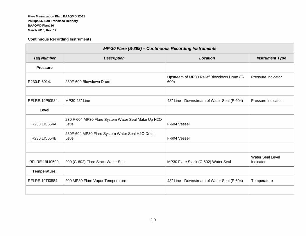
2.2.3.2 MP-30 Flare (S-398)
Flare System Flowmeters
MP-30 Flare (S-398) – Flare System Flowmeters
Tag Number Description Location Type (e.g. sonic)
Range (X – Y scfd)
Flare Gas Flow:
RFLRE:19FI0584. MP30 48" Line 48" Line - Downstream of Water Seal (F-604) Ultrasonic Flowmeter
RFLRE:19FI0584L. 48" Line - low range 0 - 2,000
RFLRE:19FI0584H. 48" Line - high range 0 - 35,070
RFLRE:19FI0585. 36" Line 36" Line - from Refinery Blowdown Line (F-2) Ultrasonic Flowmeter 0 - 120,000
RFLRE:19FI0585L. 36" Line – low range
RFLRE:19FI0585H. 36" Line – high range
Purge Gas Flow
RFLRE:19FIC0511. Natural Gas Purge Orifice Plate 0 - 930 MSCFD
1 Does not meet 12-11 accuracy requirements for all ranges. Utilized as a backup meter, when necessary.
Flare Minimization Plan, BAAQMD 12-12 Phillips 66, San Francisco Refinery BAAQMD Plant 16 March 2016, Rev. 12
2-9
Continuous Recording Instruments
MP-30 Flare (S-398) – Continuous Recording Instruments
Tag Number Description Location Instrument Type
Pressure
R230:PI6014. 230F-600 Blowdown Drum Upstream of MP30 Relief Blowdown Drum (F-600)
Pressure Indicator
RFLRE:19PI0584. MP30 48" Line 48" Line - Downstream of Water Seal (F-604) Pressure Indicator
Level
R230:LIC654A. 230:F-604 MP30 Flare System Water Seal Make Up H2O Level F-604 Vessel
R230:LIC654B. 230F-604 MP30 Flare System Water Seal H2O Drain Level F-604 Vessel
RFLRE:19LI0509. 200:(C-602) Flare Stack Water Seal MP30 Flare Stack (C-602) Water Seal Water Seal Level Indicator
Temperature:
RFLRE:19TI0584. 200:MP30 Flare Vapor Temperature 48" Line - Downstream of Water Seal (F-604) Temperature

Flare Minimization Plan, BAAQMD 12-12 Phillips 66, San Francisco Refinery BAAQMD Plant 16 March 2016, Rev. 12
2-10
MP-30 Flare (S-398) – Continuous Recording Instruments
Tag Number Description Location Instrument Type
RFLRE:19TI0529A. 200:(C-602) NW Flare Pilot Flare Tip Thermocouple
RFLRE:19TI0529B. 200:(C-602) NE Flare Pilot Flare Tip Thermocouple
RFLRE:19TI0529C. 200:(C-602) SE Flare Pilot Flare Tip Thermocouple
RFLRE:19TI0529D. 200:(C-602) SW Flare Pilot Flare Tip Thermocouple
Analyzers
RFLRE:19AI0584. 200:MP30 Flare Vapor Molecular Weight 48" Line - Downstream of Water Seal (F-604) Molecular Weight Indicator
RFLRE:19AI0502. 200:MP30 Flare Oxygen 48" Line - Downstream of Water Seal (F-604) Oxygen Content Indicator

Flare Minimization Plan, BAAQMD 12-12 Phillips 66, San Francisco Refinery BAAQMD Plant 16 March 2016, Rev. 12
2-11
2.2.3.3 Unit 200 Flare Gas Recovery Compressor (G-503)
See Attachment C and L for diagrams showing locations of meters and analyzers.
Flowmeters
Flare Gas Recovery Compressor (G-503) Flowmeters
Tag Number Description Location Type
(e.g. sonic)
Range
(X – Y MMSCFD)
Gas Flow:
R200:FI_506B. Flare Gas Recovery Compressor (G-503) Downstream of Salt Water Exchanger E-510 Orifice Plate 0 – 4.64
Monitors and Instruments
Note: All setpoints and alarms are subject to change. These values may change as operational or safety optimization opportunities are identified. This list contains the values at the time of publication.
Flare Gas Recovery Compressor (G-503) Monitors and Instruments
Flare Gas Recovery Compressor (G-503) Monitors & Instruments
Tag Number Description Location Att Setpoint or Alarms
Pressure
R200:PI0509. 200:F-509 Separator Overhead F-509 Separator Overhead C 0.5 psig Alarm
0.0 psig – Action automatic unloading of

Flare Minimization Plan, BAAQMD 12-12 Phillips 66, San Francisco Refinery BAAQMD Plant 16 March 2016, Rev. 12
2-12
Flare Gas Recovery Compressor (G-503) Monitors & Instruments
Tag Number Description Location Att Setpoint or Alarms
compressor cylinders
R200:PI0513. 200:G-503 1st Stage Downstream of 1st Stage C None
R200:PI0515. 200:G-503 2nd Stage Downstream of 2nd Stage C None
R200:PI0514. 200:G-503 Frame Oil Downstream of Frame Oil Filters L None
R200 – PAL 575 200: G-503 Frame Oil (Local Indication) Downstream of Frame Oil Filters L Shutdown Compressor - < 16 psig
Temperature
R200:TI0509. 200:F-509 Separator Overhead F-509 Separator Overhead C Alarm – 150 oF
R200:TI0511. 200:G-503 Flare Gas Recovery Compressor 1st Stage
Downstream of 1st Stage C None
R200:TI0513. 200:G-503 Flare Gas Recovery Compressor 2nd Stage
Downstream of 2nd Stage C Alarm – 300 oF
Shutdown - 350 oF
R200:TI0510. 200:G-503 Tempered Water Upstream of Exchanger E-512 L None
R200:TI0512. 200:G-503 Frame Oil Downstream of Frame Oil Pump L None
Analyzer
R200:AI0504. 200:G-503 Discharge Specific Gravity (SG) Compressor Discharge L Alarm Low SG – 0.60

Flare Minimization Plan, BAAQMD 12-12 Phillips 66, San Francisco Refinery BAAQMD Plant 16 March 2016, Rev. 12
2-13
Flare Gas Recovery Compressor (G-503) Monitors & Instruments
Tag Number Description Location Att Setpoint or Alarms
Alarm High SG – 1.12
R200 - AE503. 200:G-503 Compressor Discharge Oxygen Analyzer
Compressor Discharge L Alarm – 1.5% O2
Level Indicator
R200:L 509 200:F-509 Level Indicator (Local Indicator) F-509 Low Pressure Separator L Level is monitored by Operator.
R200 – LAH 510 200:F-509 Level Shutdown (Local Indicator) F-509 Low Pressure Separator L Shutdown Compressor – 30% Level
R200 – LAH 537 200:F-503A Level Shutdown (Local Indicator)
F-503A G-503 First Stage Suction Pulsation Dampener L Shutdown Compressor – 75% Level
R200 – LAH 538 200:F-503C Level Shutdown (Local Indicator)
F-503C: G-503 Second Station Suction Pulsation Dampener L Shutdown Compressor – 75% Level
R200 – LAH 541 200:F-503E Level Shutdown (Local Indicator)
F-503E: G-503 Second Stage Suction Knock Out Pot L Shutdown Compressor – 90% Level

Flare Minimization Plan, BAAQMD 12-12 Phillips 66, San Francisco Refinery BAAQMD Plant 16 March 2016, Rev. 12
2-14
2.2.3.4 Unit 200 Liquid Ring Flare Gas Recovery Compressors (G-540A/B/C)
Note: All data in this section is preliminary and subject to change. These values and meter numbers may change as operational or safety optimization opportunities are identified. The Compressor is undergoing a Process Hazard Analysis (PHA) at the time of the FMP update, which may result in additional changes. At this time all ranges and setpoints are being developed and thus are shown as pending.
See Attachment C and L for diagrams showing locations of meters and analyzers.
Flowmeters
Liquid Ring Flare Gas Recovery Compressor (G-540 A/B/C) Flowmeters
Tag Number Description Location Type
(e.g. sonic)
Range
(X – Y MMSCFD)
Gas Flow:
FI-1573 Liquid Ring Flare Gas Recovery Compressor (G-540A, B, & C) Flow Downstream of F-540 Gas Separator Drum Orifice 0 – 6,000 MSCFD
Service Liquid Flow:
FI-1544 (A)
FI-1545 (B)
FI-1546 (C)
Compressor Service Liquid Flow Indication, Alarm, & Shutdown To Compressor Orifice
0-200 gpm
Alarms: Low Low 100 (SD)
Low 110 gpm High 150 gpm
Monitors and Instruments

Flare Minimization Plan, BAAQMD 12-12 Phillips 66, San Francisco Refinery BAAQMD Plant 16 March 2016, Rev. 12
2-15
Note: All data in this section is preliminary and subject to change. These values may change as operational or safety optimization opportunities are identified. The Compressor is undergoing a Process Hazard Analysis (PHA) at the time of the FMP update, which may result in additional changes.
Liquid Ring Flare Gas Recovery Compressor (G-540 A/B/C) Monitors and Instruments
Liquid Ring Flare Gas Recovery Compressor (G-540 A/B/C) Monitors & Instruments
Tag Number Description Location Att Setpoint or Alarms
Pressure
PI-1541 High Pressure Alarm and Shutdown Flare Gas to Compressor C Alarm High 115.3 psig
Alarm High High 125.3 psig (SD)
PI-1543 Low & High Suction Pressure Alarm Flare Gas to Compressor C Alarm High 18.5 psia
Alarm Low 14.7 psia
PI-1881 (A)
PI-1882 (B)
PI-1883 (C)
Compressor Dual Seal Low Pressure Alarm Compressor Seal C Alarm Low 50 psig
Temperature
TI-1540 Suction Temperature Alarm and Shutdown Compressor Suction C Alarm High 150 oF
Alarm High High 170 oF (SD)
TI – 1547 (A) Compressor Temperature Discharge Gas Temperature Indication, Alarm, & Shutdown
Discharge of Compressor C Alarm High 150 oF
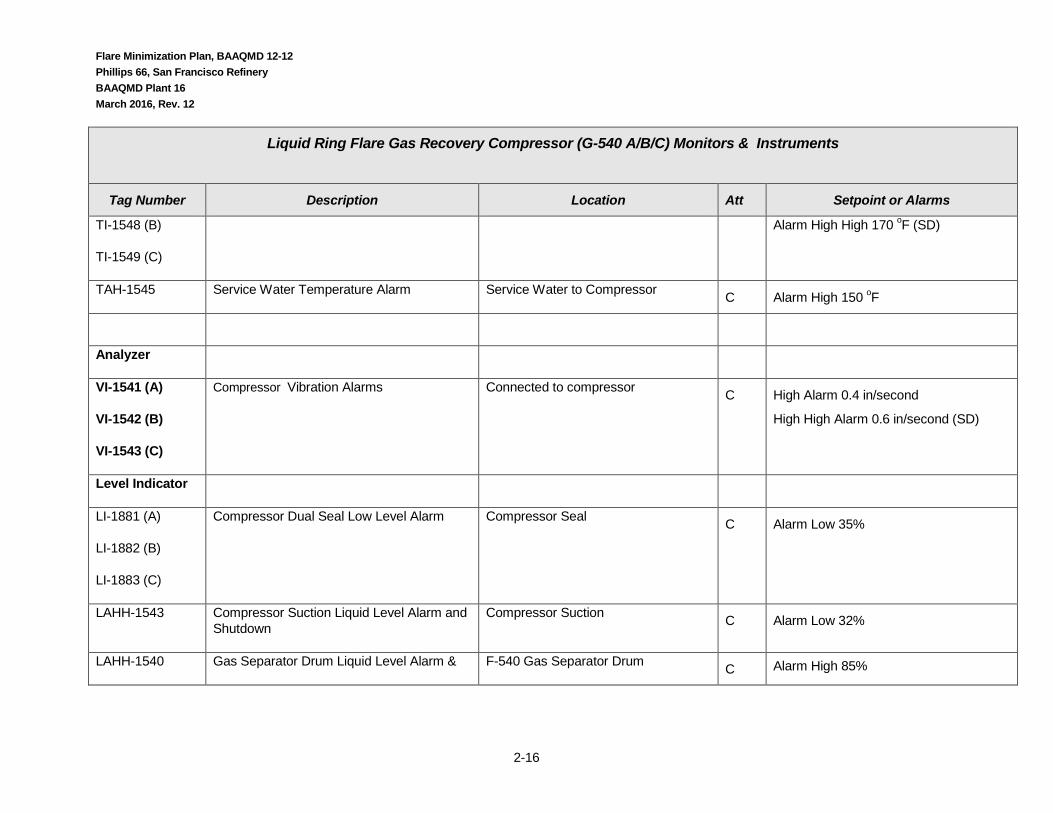
Flare Minimization Plan, BAAQMD 12-12 Phillips 66, San Francisco Refinery BAAQMD Plant 16 March 2016, Rev. 12
2-16
Liquid Ring Flare Gas Recovery Compressor (G-540 A/B/C) Monitors & Instruments
Tag Number Description Location Att Setpoint or Alarms
TI-1548 (B)
TI-1549 (C)
Alarm High High 170 oF (SD)
TAH-1545 Service Water Temperature Alarm Service Water to Compressor C Alarm High 150 oF
Analyzer
VI-1541 (A)
VI-1542 (B)
VI-1543 (C)
Compressor Vibration Alarms Connected to compressor C High Alarm 0.4 in/second
High High Alarm 0.6 in/second (SD)
Level Indicator
LI-1881 (A)
LI-1882 (B)
LI-1883 (C)
Compressor Dual Seal Low Level Alarm Compressor Seal C Alarm Low 35%
LAHH-1543 Compressor Suction Liquid Level Alarm and Shutdown
Compressor Suction C Alarm Low 32%
LAHH-1540 Gas Separator Drum Liquid Level Alarm & F-540 Gas Separator Drum C Alarm High 85%

Flare Minimization Plan, BAAQMD 12-12 Phillips 66, San Francisco Refinery BAAQMD Plant 16 March 2016, Rev. 12
2-17
Liquid Ring Flare Gas Recovery Compressor (G-540 A/B/C) Monitors & Instruments
Tag Number Description Location Att Setpoint or Alarms
Shutdown Alarm High High 99% (SD) Alarm Low 15.2% Alarm Low Low 4.3% (SD)
LAH-1542 Gas Separator High Level Alarm F-540 Gas Separator Drum Blowdown Side C Alarm Low 10%
Flare Minimization Plan, BAAQMD 12-12 Phillips 66, San Francisco Refinery BAAQMD Plant 16 March 2016, Rev. 12
3-1
3.0 Reductions & Planned Reductions
3.1 Reductions Previously Realized (401.2) Changes or Equipment in Place prior to 2003 which Prevent or Minimize Flaring
Due to economics and community concern, the refinery has a long history of flare minimization practices. The Flare Gas Recovery Compressor (G-503) was installed in the early 70’s. Up until 2000 the facility utilized a ground flare that was located near I-80. When the flare was utilized the flame was very visible from the highway. Prior to 2000 the Refinery Management had expectations for Operations to increase facility reliability to prevent upsets and to develop a means to conduct Startups & Shutdowns with minimal flaring. Those practices remain in place today.
Another item of note is the existing Sulfur Recovery Unit system. The facility has three Sulfur Recovery Units (U235, 236, & 238) which can provide for significant redundancy. This has allowed the facility to experience only one instance of acid gas flaring in the past five years from a complete refinery shutdown.
In 1999, the Unit 200 Wet Gas Compressor (G-501) seal was upgraded to a dry seal system. Previously, the seal would fail every 12 – 24 months which required a seal replacement. The seal replacement would take approximately 5 – 6 days and flaring would occur throughout this period. After the dry seals were installed, the on-line performance of the Compressor significantly improved. The compressor has not experienced a seal failure since the seal upgrade. The upgrade has resulted in a reduction of approximately 4 - 6 MMSCFD of gas flared for approximately 5 days every 12 – 24 months.
Starting in 2003 weekly updates and quarterly Key Performance Indicators (KPIs) are reported & distributed with Flaring History to all Refinery employees. The content and distribution of the KPIs is described in Environmental Services Department (ESD) Policy and Procedure 1.1 “Environmental KPIs”. The KPIs issued show trends and causes for flaring events and other reportable environmental events. The KPIs helps reduce flaring by showing all employees this is important in that it is tracked and communicated.
Flare Minimization Plan, BAAQMD 12-12 Phillips 66, San Francisco Refinery BAAQMD Plant 16 March 2016, Rev. 12
3-2
Changes Made to Reduce Flare Emissions
June 2010 to July 2015
In accordance with 401.2, listed below are reductions that have been made to reduce flaring over the past 5 years. Many of the items listed are Management System improvements. Although some of these improvements are difficult to quantify, they have had a significant impact on minimizing flaring.
Changes Made to Reduce Flare Emissions (June 2010 – July 2015)
Year Installed or
Implemented
Equipment Item Added, Process Changed or Procedure Implemented
Procedures:
1st Qtr 2013 (updated)
Refinery Policy & Procedure (P&P) 6.05-05 “Flare Monitoring & Reporting” - • Procedure created to communicate flare sampling, monitoring, & root cause analysis requirements. The contents of the
procedure include Responsibilities for personnel at the refinery in respect to flare compliance activities. • Sets standards for accountability in regards to monitoring, reporting, and preventing recurrence. • Criteria for agency release reporting (i.e. CA OES, CCC HSD, BAAQMD, NRC, etc.) for flare events. • Summary of BAAQMD 12-11 flare monitoring requirements (e.g. video, flare flow, sampling), • Summary of various regulatory reporting requirements. • Criteria for incident investigation in respect to BAAQMD regulations and the Phillips 66 EPA Consent Decree. • Means to track flare events with P66 Corporate incident tracking system.
This procedure reduces flaring by demonstrating to employees that those who have defined roles must follow the steps outlined in the procedure and that these activities are important. It also mandates expectation for consistent evaluation of flaring events & development of corrective actions to prevent recurrence.

Flare Minimization Plan, BAAQMD 12-12 Phillips 66, San Francisco Refinery BAAQMD Plant 16 March 2016, Rev. 12
3-3
Changes Made to Reduce Flare Emissions (June 2010 – July 2015)
Year Installed or
Implemented
Equipment Item Added, Process Changed or Procedure Implemented
3rd Qtr 2013 (updated)
Refinery Policy & Procedure (P&P) 10.00-01 “Incident Investigation” & Incident Investigation Training - P&P 10.00-01 establishes responsibilities, event triggers, and typical means for conducting incident investigations. The contents of the procedure include:
• Definition of the types of incidents that can occur (i.e. minor, serious, major). • Responsibilities for employees that discover an incident and who must complete tasks in respect to incident investigations. • Establishes accountability. • Description of whom and when personnel should be notified of incidents. • Defines who should participate in an incident investigation. • Description of the investigation process. • How the findings of an incident investigation are reviewed. • How findings of an incident investigation should be communicated to employees and Phillips 66 sister refineries. • How corrective actions should be addressed.
The existing procedure was updated to denote environmental related events requiring incident investigation. Flaring events are identified in the procedure. P&P 6-7 cross references P&P 5-1. This procedure reduces flaring by demonstrating to employees that those who have defined roles must follow the steps outlined in the procedure and that these activities are important. Without this procedure incidents which occur would not necessarily be investigated and addressed in a consistent fashion. The main value in flaring reduction is that this procedure requires that corrective actions be developed and addressed for incidents.
To ensure good quality investigations are conducted the facility identified key personnel to receive incident investigation training. Training ensured that first reporting (basic who, what, when, where) captures critical initial information. The training also ensures that investigations receive the necessary level of investigation and get to defined root causes. Additional work is on-going to improve and maintain the quality of the investigations conducted.

Flare Minimization Plan, BAAQMD 12-12 Phillips 66, San Francisco Refinery BAAQMD Plant 16 March 2016, Rev. 12
3-4
Changes Made to Reduce Flare Emissions (May 30, 2003 – June 30, 2010)
Year Installed or
Implemented
Equipment Item Added, Process Changed or Procedure Implemented
Procedures:
2nd Qtr 2013 (updated)
Emergency Operating Procedure EOP-1 “Guidelines for Standard Public Address System Announcements” - Enhanced Communication within the Facility when Flare Gas Recovery System Load Increases – For example, the facility Public Announcement system is currently used if an increase in the compressor load occurs. This requires process units to review their operations in order to find the cause of the increase and take actions to mitigate. This prevents some flaring events from occurring in that discretionary gases, such as nitrogen purges and hydrogen, sent to the flare gas recovery system can be scheduled around peak loading periods to maximize gases recovered. Coordination of these activities is done through Operators at various units and Shift Supervisors working together to coordinate their activities in respect to use of the flare gas blowdown system. This minimizes flaring by consciously identify periods in which the blowdown system can be utilized without overloading the flare gas recovery compressor. This results in less periods of flaring due to brief peak loading of the compressor. In addition to this process, the Public Announcement system is utilized during planned and emergency events as specified in some of the Unit 200 procedures (ESOP & NSOP-various-200) to improve equipment use and switching. For example, if the Flare Gas Recovery Compressor (G-503) is put into Wet Gas or Odor Abatement service the public announcement system will be utilized to notify plant personnel of the change in operation. Listed below is a partial list of some of the key procedures where the public announcement system use is referenced:

Flare Minimization Plan, BAAQMD 12-12 Phillips 66, San Francisco Refinery BAAQMD Plant 16 March 2016, Rev. 12
3-5
Changes Made to Reduce Flare Emissions (May 30, 2003 – June 30, 2010)
Year Installed or
Implemented
Equipment Item Added, Process Changed or Procedure Implemented
Normal Operating Procedures
• NSOP-001-200 Relief “U200 Table of Safe Operating Limits”
• NSOP-306-200 “Light Ends Shutdown, Unit Running”
• NSOP-704-200 “G-501 Compressor Shutdown & Clean-up”
• NSOP-707-200 “G-503 Flare Compressor Planned Shutdown”
• NSOP-709-200 G-503 Flare Compressor Start-up
• NSOP-710-200 “Switching G-503 to Wet Gas Service”
• NSOP-711-200 “Switching G-503 from Wet Gas to Flare Service”
• NSOP-716-200 “Switching G-503 to Odor Abatement Service”
• NSOP 717-200 “G-503 Flare Compressor Circulation”
Emergency Operating Procedures
• ESOP-700-200 “Loss of G-501 Compressor”
• ESOP-701-200 “G-503 Compressor Failure”
3rd Qtr 2013 Loss of Emergency Gas Flow to Air Liquide (REOP-25-OPS) - A new Refinery Emergency Operating Procedure (REOP) was developed in response to the June 10, 2013 flaring event after loss of RFG-A to Air Liquide. This procedure will help to reduce the flaring of sour flare gas by improved management of the RFG-A gas at Unit 240 Plant 3 and it should also reduce the overall flaring time for this type of event with improved management of the Flare Gas recovery compressors.
Equipment

Flare Minimization Plan, BAAQMD 12-12 Phillips 66, San Francisco Refinery BAAQMD Plant 16 March 2016, Rev. 12
3-6
Changes Made to Reduce Flare Emissions (May 30, 2003 – June 30, 2010)
Year Installed or
Implemented
Equipment Item Added, Process Changed or Procedure Implemented
4th Qtr 2010
Flow Meter Installation on Main & MP30 Flares – Flow meter installation per BAAQMD Regulation 12-11-501. The installation of the flow meters provides for enhanced recognition of flaring events. The flow meters help reduce flaring by providing an accurate means to measure and provide indication as to when flaring is occurring. The flow meters are especially useful for small flaring events which may not be detectable from visual flare stack monitoring only. The meters help to track and record all instances of flaring as well as giving Unit Operators immediate indication that flaring is occurring so that they can take action to reduce flaring.
Added an additional ultrasonic meter to a line that was previously only put in service every 5 -10 years. This meter (RFLRE:FI0585) went into service December 2010.
Processes:
3rd Qtr 2010 Unicracker Plant 4 Hydrogen Plant Shutdown Procedure – a new procedure for shutting down the Plant 4 Hydrogen Plant was implemented in order to reduce flaring. The revised procedure was successful and no flaring occurred during a recent shutdown. Based on past experience it was estimated this reduced 4-6 hours of flaring of gasses. This procedure was successfully implemented in 2011 as well. This Hydrogen Plant is now shutdown.
3rd Qtr 2010 Installation of Backup Lube Mist System for the G-540 Flare Gas Compressors – a backup lube oil mist system was installed for the new Flare Gas Recovery Compressors. The purpose of this system is to ensure that continuous lubrication is available to each of the compressors. If an oil mist system alarm sounds or failure occurs the backup compressor can be utilized without compressor operation loss.

Flare Minimization Plan, BAAQMD 12-12 Phillips 66, San Francisco Refinery BAAQMD Plant 16 March 2016, Rev. 12
3-7
Changes Made to Reduce Flare Emissions (May 30, 2003 – June 30, 2010)
Year Installed or
Implemented
Equipment Item Added, Process Changed or Procedure Implemented
3rd Qtr 2010 Operational Improvement – Monitoring:
Fuel System Diagnostic Tools – Developed tools for better fuel flow monitoring & optimization capability.
• PI Process Book Fuel Flow System Overviews – tool was developed to provide Supervision & Operations Engineers an overview of the fuel system operation with key parameters displayed. The key parameters shown include fuel gas produced, natural gas imported, sulfur levels in fuel, fuel consumer demand.
• PI Process Book Fuel Imbalance Optimization Tool – an online tool was developed which provide recommended steps for mitigating fuel gas imbalance. The tool lists the steps and limitations for each step which need to be optimized. ”
The use of this tool helps to reduce flaring caused due to fuel gas imbalance by providing tools & a multi unit overview of key parameters. Users of the tool can plot trends of key parameters.
1st Qtr 2011 & On-Going
Unit 110 Hydrogen Plant Startups and Shutdowns – changes have been made in how Unit 110 startups and shutdowns, when conditions warrant, to minimize flaring. For example, a shutdown takes place and human entry is not required, the unit may be purged with plant Nitrogen rather than hot, pumped Nitrogen. This allows for the Nitrogen to slowly be swept into the blowdown system, allowing for the Fuel Gas Recovery Compressor to remain operating. For some shutdowns the amount of flaring has been eliminated vs. a previous average period of of 5-1/2 hours. Unit startups have also been reduced from a period of approximately 2-1/2 hours in comparison to the previous duration of 5 hours. Throughout 2011 and 2012 efforts to minimize Unit 110 related flaring has continued by examining steps related to startup and shutdown activities. In 2013 a procedure NOP-206-110 was developed to allow for U110 startup with minimal flaring. This is partially done utilizing natural gas feed at a low rate to minimize potential flaring.
4th Quarter 2012 Flare System Rundown List (R-065) – A checklist was developed for looking for possible sources (lines and monitoring tags) at operating units which may be contributing high base load to the flare compressors and/or directly to the flare. This checklist is to be used by Shift Superintendents, Head Operators, and Unit Supervisors to pinpoint and locate higher than normal flows.
3rd Quarter 2014
Unit 110 Hydrogen Plant Control Scheme Upgrade the control scheme for Unit 110 was updated to allow for a better transition between a 10-bed to 5-bed Pressure Swing Adsorber (PSA) operation. When a need to reduce the number of operating PSA Hydrogen purification beds from 10 to 5 the feed to the unit will also automatically adjust. This will reduce the amount of Hydrogen that enters into the blowdown system and will reduce or eliminate flaring associated with this operational transition.

Flare Minimization Plan, BAAQMD 12-12 Phillips 66, San Francisco Refinery BAAQMD Plant 16 March 2016, Rev. 12
3-8
3.2 Planned Reductions (401.3)
The table below summarizes the actions currently planned to effect further reductions in refinery flaring.
Planned Actions for Reducing Flaring
Planned Actions for Reducing Flaring
Planned Date of Installation/
Implementation
Equipment Item to be Added, Process to be Changed or Procedure to be Implemented
Procedure:
Equipment
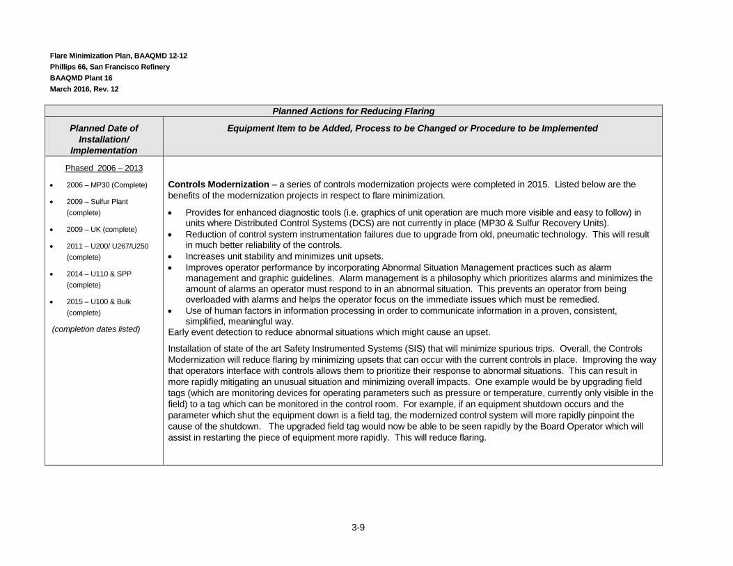
Phased 2006 – 2013
• 2006 – MP30 (complete)
• 2009 – Sulfur Plant (complete)
• 2009 – UK (complete)
• 2011 – U200/ U267/U250 (complete)
• 2014 - U110 & SPP (complete)
• 2015 – U100 & Bulk (complete)
(completion dates listed)
Construction & Operation of Central Control Room (CCR) The CCR has been built and currently contains the controls and boardmen for all the process, utility and bulk movement units. The Boardmen are the Operators that oversee the unit operation and provide direction to Outside Operators. The Boardmen were housed in Control Rooms at their individual units The CCR brings all the Boardmen together in one large control room. There is an inherent value in having the Boardmen housed in one Control Room that will minimize flaring. Improved communication will occur and better awareness of each unit’s impact upon another unit’s operation will occur. In addition, optimization by Operations Supervision will be simplified when the unit controls are housed in one Control Room. An example of this benefit is that if one unit is nitrogen purging a vessel which will add loading to the U200 G-503 Flare Gas Recovery Compressor the Boardman can immediately talk to the Unit 200 Boardman about whether or not additional loading can be handled. As the purging is taking place the two Boardmen can work closely together to monitor the impact of purging and provide immediate feedback as to the impact of the activity on the Compressor. Adjustments can be made much more quickly to manage the activity. This enhanced coordination will reduce in flaring.
Flare Minimization Plan, BAAQMD 12-12 Phillips 66, San Francisco Refinery BAAQMD Plant 16 March 2016, Rev. 12
3-9
Planned Actions for Reducing Flaring
Planned Date of Installation/
Implementation
Equipment Item to be Added, Process to be Changed or Procedure to be Implemented
Phased 2006 – 2013
• 2006 – MP30 (Complete)
• 2009 – Sulfur Plant (complete)
• 2009 – UK (complete)
• 2011 – U200/ U267/U250 (complete)
• 2014 – U110 & SPP (complete)
• 2015 – U100 & Bulk (complete)
(completion dates listed)
Controls Modernization – a series of controls modernization projects were completed in 2015. Listed below are the benefits of the modernization projects in respect to flare minimization.
• Provides for enhanced diagnostic tools (i.e. graphics of unit operation are much more visible and easy to follow) in units where Distributed Control Systems (DCS) are not currently in place (MP30 & Sulfur Recovery Units).
• Reduction of control system instrumentation failures due to upgrade from old, pneumatic technology. This will result in much better reliability of the controls.
• Increases unit stability and minimizes unit upsets. • Improves operator performance by incorporating Abnormal Situation Management practices such as alarm
management and graphic guidelines. Alarm management is a philosophy which prioritizes alarms and minimizes the amount of alarms an operator must respond to in an abnormal situation. This prevents an operator from being overloaded with alarms and helps the operator focus on the immediate issues which must be remedied.
• Use of human factors in information processing in order to communicate information in a proven, consistent, simplified, meaningful way.
Early event detection to reduce abnormal situations which might cause an upset.
Installation of state of the art Safety Instrumented Systems (SIS) that will minimize spurious trips. Overall, the Controls Modernization will reduce flaring by minimizing upsets that can occur with the current controls in place. Improving the way that operators interface with controls allows them to prioritize their response to abnormal situations. This can result in more rapidly mitigating an unusual situation and minimizing overall impacts. One example would be by upgrading field tags (which are monitoring devices for operating parameters such as pressure or temperature, currently only visible in the field) to a tag which can be monitored in the control room. For example, if an equipment shutdown occurs and the parameter which shut the equipment down is a field tag, the modernized control system will more rapidly pinpoint the cause of the shutdown. The upgraded field tag would now be able to be seen rapidly by the Board Operator which will assist in restarting the piece of equipment more rapidly. This will reduce flaring.

Flare Minimization Plan, BAAQMD 12-12 Phillips 66, San Francisco Refinery BAAQMD Plant 16 March 2016, Rev. 12
3-10
Planned Actions for Reducing Flaring
Planned Date of Installation/
Implementation
Equipment Item to be Added, Process to be Changed or Procedure to be Implemented
County Land Use Permit Appealed (as of October, 2015)
Propane Recovery Project – The Authority to Construct for this project application was issued by BAAQMD on March 18, 2015. The purpose of the project is to recovery propane and butane from the refinery fuel gas (RFG). Another aspect of the project is to remove a portion of the sulfur compounds from the remaining Refinery Fuel Gas (RFG). From a flaring standpoint, this project is beneficial in reducing overall volume of Refinery Fuel Gas. The propane and butane will be replaced by natural gas provided by PG&E. Because it is relatively easy to reduce the amount of natural gas being imported, the likelihood of flaring due to fuel gas imbalance will be reduced. In addition, by reducing the concentration of sulfur in fuel gas this removes some of the restrictions on where fuel gas can be routed which further helps to minimize and reduce periods of potential fuel gas imbalance.
Processes:
On-going Improved Incident Analysis Investigation – Continue to complete required 12-12 Root Cause analysis and analysis triggered by internal incident investigation drivers. Investigations and corrective actions identified will continue to address issues that may result in flaring if not otherwise addressed. The root cause analysis requires that the facility find the actual cause of flaring, down to a single part that may have failed in some instances. The 12-12 analysis also requires the facility to identify changes that can be made to prevent flaring and list those in the root cause analysis submittal to BAAQMD. This results in the facility taking action to prevent recurrence of flaring events. For example, some of the recent root cause analysis have identified equipment upgrades that should be made, additional training to be conducted, equipment repairs, etc.
Flare Minimization Plan, BAAQMD 12-12 Phillips 66, San Francisco Refinery BAAQMD Plant 16 March 2016, Rev. 12
3-11
Planned Actions for Reducing Flaring
Planned Date of Installation/
Implementation
Equipment Item to be Added, Process to be Changed or Procedure to be Implemented
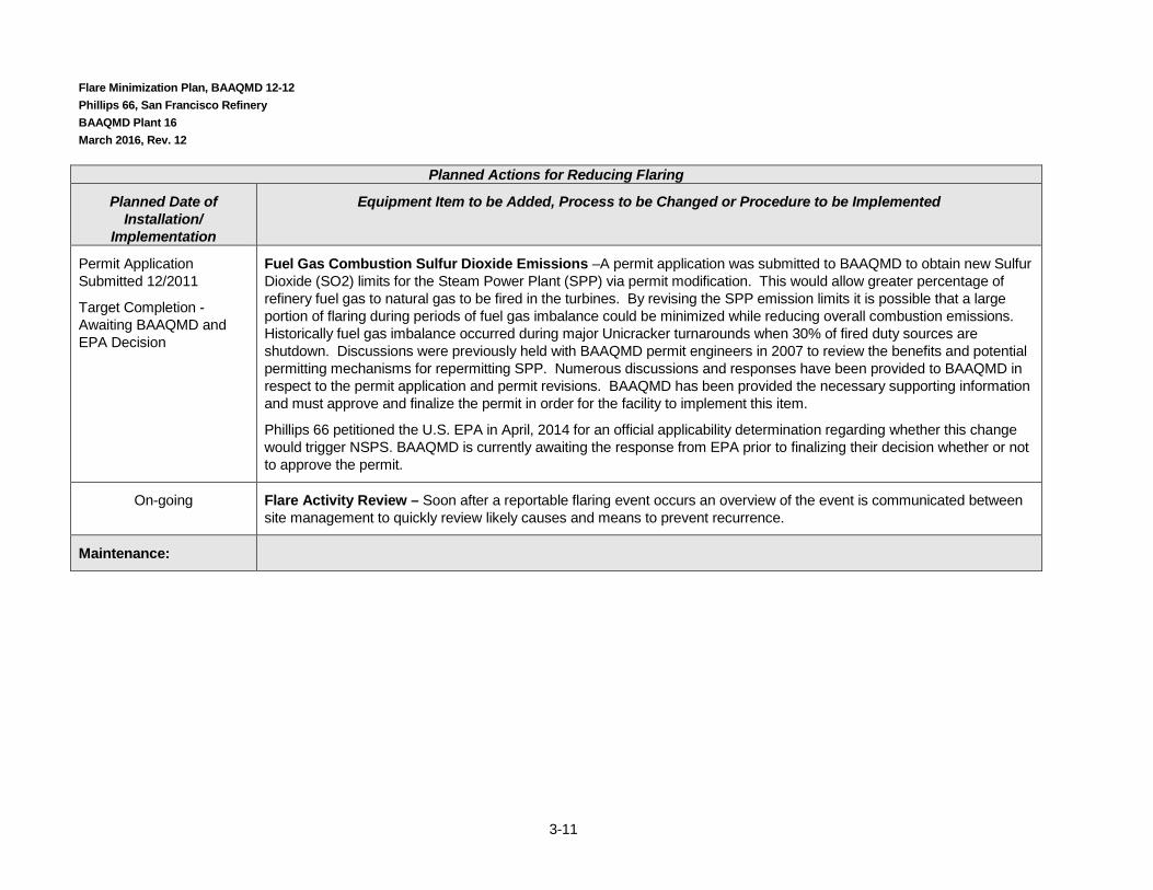
Permit Application Submitted 12/2011
Target Completion -Awaiting BAAQMD and EPA Decision
Fuel Gas Combustion Sulfur Dioxide Emissions –A permit application was submitted to BAAQMD to obtain new Sulfur Dioxide (SO2) limits for the Steam Power Plant (SPP) via permit modification. This would allow greater percentage of refinery fuel gas to natural gas to be fired in the turbines. By revising the SPP emission limits it is possible that a large portion of flaring during periods of fuel gas imbalance could be minimized while reducing overall combustion emissions. Historically fuel gas imbalance occurred during major Unicracker turnarounds when 30% of fired duty sources are shutdown. Discussions were previously held with BAAQMD permit engineers in 2007 to review the benefits and potential permitting mechanisms for repermitting SPP. Numerous discussions and responses have been provided to BAAQMD in respect to the permit application and permit revisions. BAAQMD has been provided the necessary supporting information and must approve and finalize the permit in order for the facility to implement this item.
Phillips 66 petitioned the U.S. EPA in April, 2014 for an official applicability determination regarding whether this change would trigger NSPS. BAAQMD is currently awaiting the response from EPA prior to finalizing their decision whether or not to approve the permit.
On-going Flare Activity Review – Soon after a reportable flaring event occurs an overview of the event is communicated between site management to quickly review likely causes and means to prevent recurrence.
Maintenance:

Flare Minimization Plan, BAAQMD 12-12 Phillips 66, San Francisco Refinery BAAQMD Plant 16 March 2016, Rev. 12
3-12
Planned Actions for Reducing Flaring
Planned Date of Installation/
Implementation
Equipment Item to be Added, Process to be Changed or Procedure to be Implemented
On-going G-503/G-540 Flare Gas Recovery Compressors - this practice began more than 5 years ago and continues to date. Approximately every 18 months, in association with a major unit turnaround, the G-503 Flare Gas Recovery Compressor is taken out of service for a major overhaul. The purpose is to maintain critical equipment associated with the compressor in order to prevent unplanned failures. This practice minimizes overall downtime for the compressor. The work is scheduled with a major turnaround since gasses produced at the facility are at reduced rates and many fuel gas consumers are out of service. Without this maintenance it is more likely that the compressor would experience unplanned failures during periods when high gas volumes are being produced. The unplanned failure repair is of longer duration because the personnel and equipment must be assembled without advanced planning. In many cases, diagnosis must be performed to determine the failure and this can take considerable time. Whereas, planned maintenance prevents many of these types of failures from occurring. As with regular maintenance on a vehicle, this maintenance performs a similar purpose.
Now that the new Liquid Ring Flare Gas Recovery Compressor has been installed all flare gas recovery compressors will be maintained on a routine basis yet it will be done when the spare compressor(s) are in operation which will further reduce overall flare emissions.

Flare Minimization Plan, BAAQMD 12-12 Phillips 66, San Francisco Refinery BAAQMD Plant 16 March 2016, Rev. 12
4-1
4.0 Prevention Measures (401.4)
4.1 “Major” Maintenance Activities (401.4.1) This section discusses refinery maintenance and turnaround activities, outlines measures to minimize flaring during both preplanned and unplanned maintenance activities. A description of flaring that occurs during major maintenance activities is included in this section and in the section titled “When Flaring is Likely to Occur” in accordance to 401.4.1. As required by 401.4.1 a review of flaring associated with major maintenance has been conducted and is referenced below. The measures taken to prevent flaring during portions of major maintenance activities are included in the section titled “Measures to Minimize Flaring During Preplanned Maintenance”.
4.1.1 Refinery Maintenance and Turnaround Activities Maintenance activities often result in a higher than normal flow of material to the flare gas recovery system. In order to maintain process equipment, the first step is to clear the process equipment and associated piping of hydrocarbons, before the system is opened to the atmosphere, for both safety and environmental reasons, including compliance with BAAQMD Regulation 8 Rule 10, (Process Vessel Depressurization). How this is accomplished depends on the physical properties of the hydrocarbons to be removed (vapor pressure, viscosity) and on the process details of the equipment that is to be maintained.
The first step is to recover as much of the hydrocarbon as is possible by transferring it to a process unit that is not in the part of the refinery that is being prepared for maintenance. For example, liquid hydrocarbons can be pumped to tankage or another process system; gases under pressure may be depressurized to another process unit. Heavy hydrocarbons that are viscous at ambient temperatures are often displaced from the equipment to be maintained using lighter hydrocarbons, e.g. diesel type material. This material can then be pumped from the equipment.
Although depressurization and pump-out can be used to remove the bulk of the hydrocarbon from the equipment, they leave some residual material. Following pump-out or depressurization to other process equipment, the next step in decommissioning typically requires a low-pressure location that has the ability to accept a wide range of hydrocarbon materials in order to avoid putting these materials to the atmosphere. The flare gas header is the only location within the refinery that meets these criteria. Equipment items containing materials that are gases at ambient temperature and pressure are often vented to the flare gas recovery system so that the hydrocarbon can be recovered as fuel gas. To free the equipment of hydrocarbons following depressurization, they can be purged using an inert gas such as nitrogen. Alternatively nitrogen can be added to the equipment increasing the internal pressure. The resulting mixture of nitrogen and hydrocarbon can then be released to the flare header, reducing the pressure in the equipment. Steam can be substituted for nitrogen in some cases, but not for processes that need to be kept dry in order to avoid corrosion or catalyst damage, or for some other reason.
For equipment containing liquids, often steam or nitrogen are used to “blow” the liquid to the flare header. The liquid hydrocarbon and condensed steam are separated from the vapor phase and returned to the refinery’s recovered oil system and to wastewater treatment either at the unit knockout drum or at the flare knockout drum. Nitrogen with hydrocarbon vapor continues on to flare gas recovery. Once the bulk of the liquid hydrocarbon has been displaced, the flow of steam or nitrogen is continued to remove any residual hydrocarbon by vaporization. Steam can be more effective for heavier materials as it increases their volatility by increasing temperature. Proprietary solvents such

Flare Minimization Plan, BAAQMD 12-12 Phillips 66, San Francisco Refinery BAAQMD Plant 16 March 2016, Rev. 12
4-2
as “Zyme-flow” are sometimes used in aqueous solution for removal of residual hydrocarbons. When aqueous solvents are used, they are typically circulated in the equipment and then treated.
Although these procedures eliminate hydrocarbon emissions related to equipment opening, they require a high volumetric, high velocity, steam or nitrogen flowrate in order to be effective. This high flowrate of inert gas can create several sets of circumstances where flare gas recovery is not feasible. These problems relate either to the change in fuel gas composition (increased molecular weight or temperature) or to the increase in volumetric flowrate.
In addition to an increase in flare gas average molecular weight from higher than normal nitrogen flowrate, there is also the potential for much lower than average molecular weight gas from increased flow of hydrogen. There are many process and reactor systems within a refinery that contain gases with a high hydrogen content. When this equipment is decommissioned by depressurization to the flare gas header, there can be a sharp decrease in the flare gas average molecular weight.
Effect of Flare Gas on Downstream Equipment
Gas composition affects the equipment in the flare gas recovery system. Specifically:
• High nitrogen content can impact heaters, boilers and the flare gas compressor.
• Hydrogen and other low molecular weight gases impact flare gas compressor performance.
• Steam impacts knock out drums and compressors.
High flows of nitrogen from equipment purging leads to a much higher than normal inert content in the recovered flare gas, greatly reducing its fuel value (measured as Btu/scf) and increasing its molecular weight. Reciprocating compressor (G-503) increase the pressure of a constant inlet volumetric flowrate of gas. For a given volume of gas, an increase in molecular weight creates an increase in its mass. This increases the work that the compressor has to do to compress the gas, overloading and potentially damaging the machine.
For a reciprocating compressor, the compression ratio (ratio of outlet pressure to inlet pressure) is high enough that more than one stage of compression is needed. The temperature of the gas increases as it is compressed. The gas is cooled between stages in order to control the temperature increase. Operation of a reciprocating compressor with a feed stream that has a molecular weight outside of the range for which it was designed (e.g. high hydrogen content) can lead to a temperature increase exceeding the design limitations of the machine. Flare Gas Compressor (G-503) is shutdown in order to protect it from failure that could be caused by a decrease in molecular weight.
The Liquid Ring compressors are expected to have a wider range of operating conditions. The compressors and associated control system will have enhanced monitoring in comparison with the existing Reciprocating Compressor. There will still be limitations on the type of gases that should be recovered and utilized in the fuel gas system (i.e. high volumes of hydrogen potentially impacting Btu values).
Additionally, if low Btu flare gas is transferred to the fuel gas header, the lower fuel value can have the effect of reducing combustion efficiency, as the combustion device burners are designed to operate with fuels that have higher heat content per cubic foot. In extreme cases, the heating value of the gas can be reduced by dilution with nitrogen to the point of extinguishing the burner flame. This creates the potential for unburned fuel to accumulate in the heater or boiler, potentially leading to an explosion when it is re-ignited. NFPA 85 – Boiler and Combustion Systems Hazards Code and NFPA 86 Standards for Ovens and Furnaces warn against this possibility.
A major advantage of using steam to clear hydrocarbons from equipment is its elevated temperature; however this can be a disadvantage with respect to flare gas recovery. When the distance the gas must travel to reach the flare gas compressor is large, (the flare header is long), the gas will cool, and

Flare Minimization Plan, BAAQMD 12-12 Phillips 66, San Francisco Refinery BAAQMD Plant 16 March 2016, Rev. 12
4-3
much of the steam will condense and be removed as water at the knock-out drum. However; with a shorter flare line or a long-duration steam out event, the temperature of the flare gas at the flare gas compressor can be elevated significantly. If the temperature of the flare gas stream at the inlet to the flare gas compressor exceeds machine limits, the gas must be diverted away from the compressor inlet in order to avoid mechanical damage.
Summary
Each of the situations described above potentially leads to the need to divert gas produced during refinery maintenance away from the flare gas recovery compressor and to a flare. This is a necessary result of maintenance procedures which have been adopted to minimize the release of hydrocarbons to the atmosphere during equipment opening. The need to divert gas is driven by the quantity and composition of the gases produced during equipment shutdown and startup.
Major maintenance activities can result in flaring, as discussed above. A review of maintenance-related flaring from 2000 to 2006 at the Phillips 66 San Francisco refinery in Rodeo has been completed. Due to the requirement to install flowmeters and report flare emissions to BAAQMD the data from September 2003 to date is the most accurate for this review. Subsequent flaring taking place during equipment startups and shutdowns are being examined as part of the Turnaround Planning Flare Minimization Process and causal analysis being conducted.
Based on the review there were means of further reducing and/or eliminating flaring that were identified. Included below is a summary of the measures identified and rationale for the acceptance or rejection of the concept:

Flare Minimization Plan, BAAQMD 12-12 Phillips 66, San Francisco Refinery BAAQMD Plant 16 March 2016, Rev. 12
4-4
Major Maintenance Prevention Measure Evaluation
This is a list of prevention measures that were identified based on the 5-year look back of Major Maintenance activities. Attachment H is a summary of all flaring events and is grouped by category. Based on the 5-year look back the following types of flaring were identified for elimination:
• Flaring associated with Hydrogen Unit Startups/Shutdowns (H2 SU/SD) • Flaring due to G-503 Flare Gas Recovery Compressor Planned Maintenance (G-503 PM) • General Flaring Associated with Major Maintenance (.e.g. nitrogen purging, steaming, etc.) (General)
Major Maintenance – Prevention Measure Evaluation
Measure Description
Schedule for Implementation
Rationale to Support Schedule Type of Flaring that would be Reduced or Eliminated
Rationale for Rejecting Measure
Section Reference
(for more details)
Addition of Unit 110 Hydrogen Vent
• Dec. 2006
•
Installation of a vent which will allow a small stream of purified hydrogen to be vented.
H2 SU/SD n/a 3.2
Odor Abatement/Flare Gas Recovery System Optimization
• October 2008 – Construction Start
• August 2009 (completed)
A set of 3 Liquid Ring Compressors were installed in order to provide redundant and extra capacity for the Flare Gas Recovery compressor. This will eliminate some flaring events that have historically occurred by having additional flare gas recovery service. A separate odor abatement compressor was installed which will provide further reliability for the odor abatement system.
G-503 SU/SD
G-503 Brief Peak Loading
Completed 3.2
Turnaround (T/A) Planning Procedure
4th Qtr 2006 Being coordinated with submittal of Flare Minimization Plan.
H2 SU/SD
G-503 PM
General
n/a 4.1.3
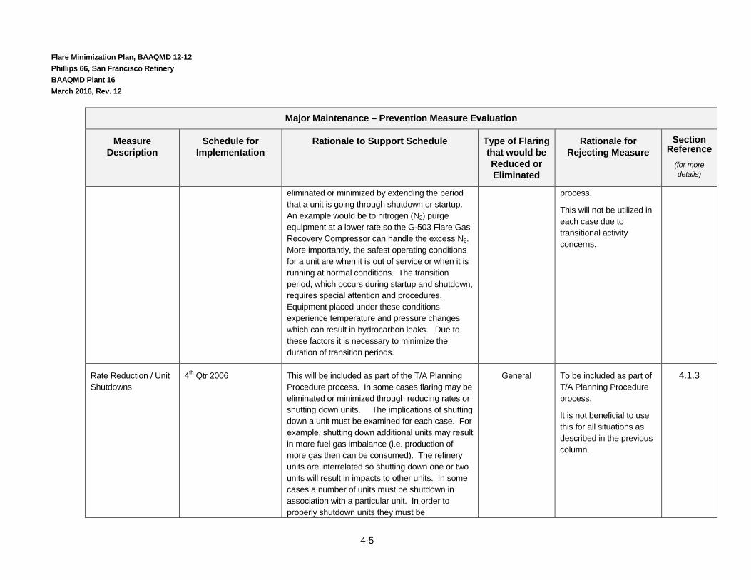
Shutdown & Startup Activity Extension
4th Qtr 2006 This will be included as part of the T/A Planning Procedure. In some cases flaring may be
General To be included as part of T/A Planning Procedure
4.1.3
Flare Minimization Plan, BAAQMD 12-12 Phillips 66, San Francisco Refinery BAAQMD Plant 16 March 2016, Rev. 12
4-5
Major Maintenance – Prevention Measure Evaluation
Measure Description
Schedule for Implementation
Rationale to Support Schedule Type of Flaring that would be Reduced or Eliminated
Rationale for Rejecting Measure
Section Reference
(for more details)
eliminated or minimized by extending the period that a unit is going through shutdown or startup. An example would be to nitrogen (N2) purge equipment at a lower rate so the G-503 Flare Gas Recovery Compressor can handle the excess N2. More importantly, the safest operating conditions for a unit are when it is out of service or when it is running at normal conditions. The transition period, which occurs during startup and shutdown, requires special attention and procedures. Equipment placed under these conditions experience temperature and pressure changes which can result in hydrocarbon leaks. Due to these factors it is necessary to minimize the duration of transition periods.
process.
This will not be utilized in each case due to transitional activity concerns.
Rate Reduction / Unit Shutdowns
4th Qtr 2006 This will be included as part of the T/A Planning Procedure process. In some cases flaring may be eliminated or minimized through reducing rates or shutting down units. The implications of shutting down a unit must be examined for each case. For example, shutting down additional units may result in more fuel gas imbalance (i.e. production of more gas then can be consumed). The refinery units are interrelated so shutting down one or two units will result in impacts to other units. In some cases a number of units must be shutdown in association with a particular unit. In order to properly shutdown units they must be
General To be included as part of T/A Planning Procedure process.
It is not beneficial to use this for all situations as described in the previous column.
4.1.3
Flare Minimization Plan, BAAQMD 12-12 Phillips 66, San Francisco Refinery BAAQMD Plant 16 March 2016, Rev. 12
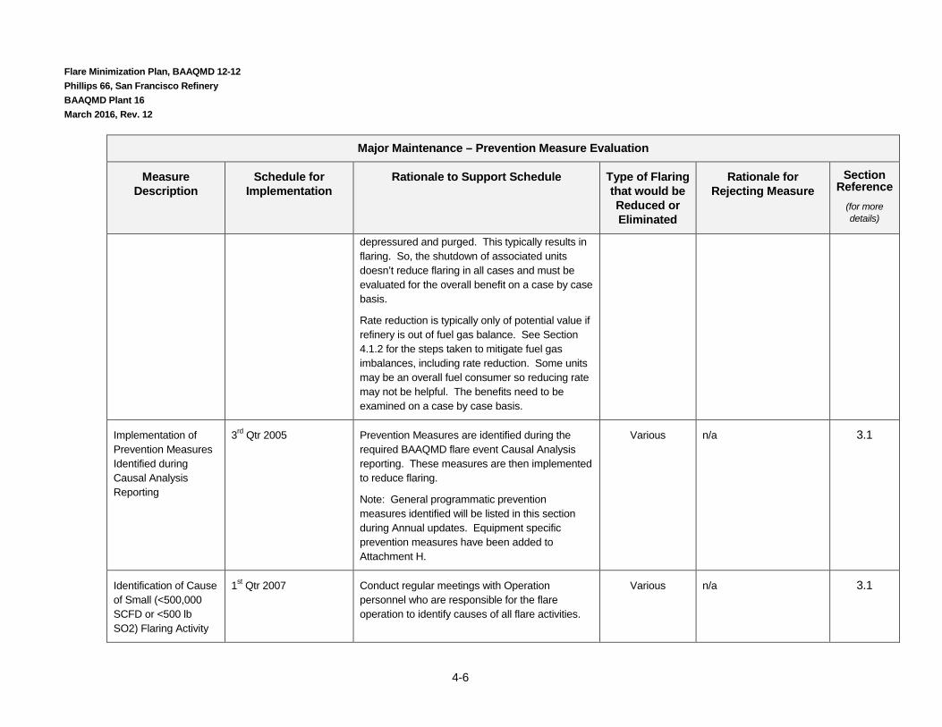
4-6
Major Maintenance – Prevention Measure Evaluation
Measure Description
Schedule for Implementation
Rationale to Support Schedule Type of Flaring that would be Reduced or Eliminated
Rationale for Rejecting Measure
Section Reference
(for more details)
depressured and purged. This typically results in flaring. So, the shutdown of associated units doesn’t reduce flaring in all cases and must be evaluated for the overall benefit on a case by case basis.
Rate reduction is typically only of potential value if refinery is out of fuel gas balance. See Section 4.1.2 for the steps taken to mitigate fuel gas imbalances, including rate reduction. Some units may be an overall fuel consumer so reducing rate may not be helpful. The benefits need to be examined on a case by case basis.
Implementation of Prevention Measures Identified during Causal Analysis Reporting
3rd Qtr 2005 Prevention Measures are identified during the required BAAQMD flare event Causal Analysis reporting. These measures are then implemented to reduce flaring.
Note: General programmatic prevention measures identified will be listed in this section during Annual updates. Equipment specific prevention measures have been added to Attachment H.
Various n/a 3.1
Identification of Cause of Small (<500,000 SCFD or <500 lb SO2) Flaring Activity
1st Qtr 2007 Conduct regular meetings with Operation personnel who are responsible for the flare operation to identify causes of all flare activities.
Various n/a 3.1
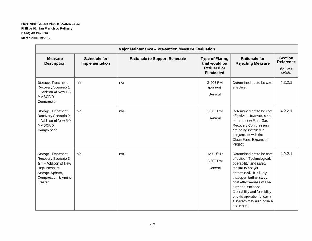
Flare Minimization Plan, BAAQMD 12-12 Phillips 66, San Francisco Refinery BAAQMD Plant 16 March 2016, Rev. 12
4-7
Major Maintenance – Prevention Measure Evaluation
Measure Description
Schedule for Implementation
Rationale to Support Schedule Type of Flaring that would be Reduced or Eliminated
Rationale for Rejecting Measure
Section Reference
(for more details)
Storage, Treatment, Recovery Scenario 1 – Addition of New 1.5 MMSCF/D Compressor
n/a n/a G-503 PM (portion)
General
Determined not to be cost effective.
4.2.2.1
Storage, Treatment, Recovery Scenario 2 – Addition of New 6.0 MMSCF/D Compressor
n/a n/a G-503 PM
General
Determined not to be cost effective. However, a set of three new Flare Gas Recovery Compressors are being installed in conjunction with the Clean Fuels Expansion Project.
4.2.2.1
Storage, Treatment, Recovery Scenario 3 & 4 – Addition of New High Pressure Storage Sphere, Compressor, & Amine Treater
n/a n/a H2 SU/SD
G-503 PM
General
Determined not to be cost effective. Technological, operability, and safety feasibility not yet determined. It is likely that upon further study cost effectiveness will be further diminished. Operability and feasibility of safe operation of such a system may also pose a challenge.
4.2.2.1
Flare Minimization Plan, BAAQMD 12-12 Phillips 66, San Francisco Refinery BAAQMD Plant 16 March 2016, Rev. 12
4-8
Section 4.1.2 contains a list of measures that are currently in practice for reducing flaring.
From this review it is clear that one of the greatest potentials for achieving further cost-effective reductions in flaring lie in maintenance planning with flare minimization as a goal coupled with the existing goals of safety and minimizing production impacts due to extended downtimes. The essential component of any plan that satisfies maintenance needs while minimizing flaring is that it must mitigate or eliminate the conditions described in the sections above that make recovery of flare gas impossible. In practical terms this means taking a series of actions specific to the unit being decommissioned to limit the rate at which flare gas is generated and maintain its temperature and composition within a range acceptable for transfer via a flare gas compressor and for use in the fuel gas system. Concepts for accomplishing this are discussed in the section following.
4.1.2 Measures to Minimize Flaring During Preplanned Maintenance In accordance with 401.4.1 in regards to feasible prevention measures that can be used to minimize future flaring: (including that related to scheduled process unit turnarounds and immediate near-term shutdowns) are listed below. Numerous prevention measures are utilized to prevent flaring from occurring during portions of major maintenance events. The information is organized by process unit and by topic. There are also some general measures listed that are used at most units, when applicable. Refer to Attachment E for list of unit names and numbers. It is noted that although prevention measures are routinely employed, as explained in the previous section, all flaring cannot be eliminated due to gas quality and quantity issues associated with major maintenance activities.
Hydroprocessing (U228, U229, U230, U231, U240-2, U244, U248, U250)
Hydroprocessing units are depressurized to hydrogen recovery, or other lower pressure locations , and only after this are they depressurized to flare gas recovery, reducing the load on the flare gas recovery system. This prevents flaring by minimizing load on the flare gas recovery system and decreases the period of time in which flaring occurs during venting activities.
Following depressurization, the remaining hydrocarbon is removed by increasing the pressure in the equipment with nitrogen and then depressurizing it to flare gas recovery multiple times. Doing this quickly helps with mixing, which improves removal of hydrocarbon from the vessel so that fewer cycles are needed. This minimizes the volume of low quality gasses that are sent to the flare.
Depressurization of the unit to the flare gas recovery system is staged in order to minimize exceeding the capacity or quality parameters of the system in order to maximize the time in which the flare gas recovery compressor is on-line. The longer the flare gas recovery compressor is on-line the less flaring that occurs.
Gases are recirculated using the hydrogen recycle compressors as the reactors cool. When the equipment is cooled and at low pressure, nitrogen pressurization and release steps are used to clear hydrocarbons. Hydrogen-containing streams are directed to the hydrogen plant. Use of hydrogen recycle for cooling and cleaning minimizes the need for nitrogen which, when utilized, typically results in flaring.
U250 - A high pressure hydrotreater design is used to avoid flow to the flare by containing the process during loss of utilities. Without this design, additional volume of materials would be sent to the flare during loss of utilities. See Section 3.1 for more details on elements of this design.

Flare Minimization Plan, BAAQMD 12-12 Phillips 66, San Francisco Refinery BAAQMD Plant 16 March 2016, Rev. 12
4-9
Reformer (U231, U244) The timing of the steps involved in the regeneration cycle are controlled and the venting / depressuring rate limited to be within the capacity of the compressors. This minimizes the total vent stream that must be sent to the flare.
Delayed Coker (U200) The delayed coker drum cooling cycle time is coordinated with other activities to prevent exceeding the Flare Gas Recovery Compressor capacity.
Fractionation Units (Various units, throughout refinery) Vents from depressurization of fractionation units are recovered using the flare gas compressor system rather than being routed to the flare, when capacity is available or gas quality allows. This minimizes flaring by reducing the volume of gasses that must be sent to the flare.
Compressor (U200 Flare & Blowdown System)
Compressor Maintenance In some instances, the flare gas recovery compressor (G-503) is placed in wet gas recovery compressor service (G-501) if the wet gas compressor is expected to be offline. This minimizes the total amount of gas flared. A greater volume of gas can be recovered by placing G-503 directly in Wet Gas service rather than directing the Wet Gas into the blowdown system. Recovering higher rates of gas reduces the volume recovered.
Flare gas compressors are maintained during planned unit shutdowns, to improve reliability during periods of normal operation. A planned shutdown provides an opportunity to do maintenance while flare system load is lower.
In the future, when the redundant new Liquid Ring Flare Gas Recovery Compressors are operational planned maintenance scheduling will be optimized and staggered to minimize and/or prevent flare gas recovery outages for compressor maintenance.
Regular preventative maintenance of flare gas compressors, as described further in Section 3.2, is used to improve their reliability.
Maintenance is also conducted on compressors based on critical monitoring (i.e. vibration, temperature, load) results.
Flare System Monitoring
Flare Gas Recovery Compressor load is monitored to identify & mitigate higher than normal baseline load. High loads are mitigated by identifying the source and making reductions. For example, if a PRV is venting to blowdown then the responsible unit will be identified and directed to make adjustments to prevent the PRV from venting.
The flare gas recovery compressor is monitored when maintenance is being conducted at other units that will cause the compressor to be taken off-line. The purpose is to minimize the amount of compressor downtime in order to protect the compressor and minimize the total time the compressor is shutdown and reduce overall flaring.

Flare Minimization Plan, BAAQMD 12-12 Phillips 66, San Francisco Refinery BAAQMD Plant 16 March 2016, Rev. 12
4-10
Plant personnel who oversee flare gas recovery systems have been instilled with an improved understanding. The operators monitor flare gas compressor load to check for high load or load changes, record instances of flaring and potential causes, take action to minimize flaring, and notify Shift Superintendents when flaring occurs. This results in conscious management of the flare system to minimize flaring.
Flow and/or temperature measurement as a means of indicating flow in each flare header is used to identify and eliminate sources of flow to the flare gas header. Indication of flow during periods when flow is not expected is a direct indication of flaring. As described above, operators respond to flaring events by attempting to track the source and working with the Shift Superintendent to take action to make reductions or eliminate flaring.
The monitoring parameters available for the Liquid Ring Compressors will be more robust and provide more on-line indication of changes in flare gas quality. This enhanced monitoring will likely assist in the optimization of compressor on-line performance.
On-line diagnostic tools are utilized to monitor flows to the flare in order to minimize flaring duration. See Section 3.1 “Operational Improvement – Monitoring” for more details on how these tools reduce flaring.
When higher than normal flare gas recovery compressor loads are detected announcements are made throughout the refinery in order to proactively identify and address the source of gases. See Section 3.1 Emergency Operating Procedure EOP-1 “Guidelines for Standard Public Address System Announcements” for more details.
Fuel Gas Scrubbing
Gases collected by the flare gas compressor are scrubbed whenever possible. This includes periods of fuel gas imbalance and periods when the compressor capacity is exceeded but the compressor is still operational. This results in reduced sulfur dioxide emissions from the flare.
Sulfur Recovery Units (U235, 236, & 238)
The refinery has three sulfur recovery units operating in parallel. During periods of maintenance the load is shifted from one unit to the others. Thus, no flaring is necessary during unit startups or shutdowns. Additionally, sulfur load can readily be reduced by decreasing sour water stripping. The Refinery has not historically experienced acid gas flaring during sulfur plant startups & shutdowns or upsets.
General Measures (used at various units, as applicable)
Liquid Vessel Cleanup Chemical cleaning is used to so that cleanup is faster, minimizing the time needed for steam out. Chemical cleaning works similar to using dish soap on greasy dishes in that cleaning time and rinse water is minimized. Thus, in practice overall time in which steaming must occur is minimized, thus minimizing flaring. Chemical cleaning is primarily used in units where there is a high volume of residual oil and solids in equipment and piping. Chemical cleaning must be balanced with wastewater treatment plant capabilities.
Depressurization Separate flare gas headers are in place at the Unicracker Complex for the Reactor section and Hydrogen Plant so that some gases produced during maintenance, startup, and

Flare Minimization Plan, BAAQMD 12-12 Phillips 66, San Francisco Refinery BAAQMD Plant 16 March 2016, Rev. 12
4-11
shutdown can be directly routed to the flare. This minimizes the volume of gases sent to the flare during maintenance activities since it provides a separate system from the refinery blowdown system. This allows a portion of the refinery gasses to be recovered while only those from the Unicracker are sent to the flare.
Pressure Relief Routine maintenance of PRDs, consistent with API 510, is used to minimize “routine” flow to the flare gas header. The purpose of the maintenance is to ensure the PRDs are operating properly at the appropriate set points and not relieving prior to the intended set point. Proper operation of PRDs provides a safe operation, reduces the base load and allows the system to better able to handle flow peaks during maintenance or other periods where there is additional flow in the blowdown system.
Source Reduction
If there are indications of increased base load to the flare gas compressor efforts are taken to identify and mitigate or minimize the source of gasses. This is done by identifying the flare header affected by use of monitoring parameters, as available, such as flare header flow meters, pressure and temperature indicators.
Shutdown/Startup Planning & Scheduling A specific plan will be developed to minimize flaring during each turnaround, as each is unique. Specific actions depend on which parts of the unit are being brought down and which other units are down at the same time. Note: Historically this has taken place for major turnarounds, this will be expanded to minor turnarounds as well.
Specific “flare planning” has been conducted in respect to major turnarounds.
Plans have been prepared to insure there will be a viable fuel balance during each time period during the shutdown.
The length of the shutdown has been extended in some cases to allow equipment to be purged at lower rates that can be handled by the flare gas recovery system. Extension of shutdown length will be considered as part of the turnaround planning procedure referenced in Section 2. There are limitations to this activity. The safest operating condition for a unit is either when it is out of service or when it is running at normal conditions. The transition period, which occurs during startup and shutdown, requires special attention and procedures. Equipment placed under these conditions experience temperature and pressure changes during the transition period which can result in hydrocarbon loss. Due to these factors it is necessary to minimize the duration of transition periods.
Rate Reductions and Unit Shutdowns at interrelated units occur to balance inventory. This will be included as part of the T/A Planning Procedure process referenced in Section 2. The implications of shutting down a unit must be examined for each case. For example, shutting down additional units may result in more fuel gas imbalance (i.e. production of more gas then can be consumed). The refinery units are interrelated so shutting down one or two units will result in impacts to other units. In some cases a number of units must be shutdown in association with a particular unit. In order to properly shutdown units they must be depressured and purged. This typically results in flaring. So, the shutdown of associated units doesn’t reduce flaring in all cases and must be evaluated for the overall benefit on a case by case basis.

Flare Minimization Plan, BAAQMD 12-12 Phillips 66, San Francisco Refinery BAAQMD Plant 16 March 2016, Rev. 12
4-12
Rate reduction is typically only of potential value if refinery is out of fuel gas balance. Again, the big picture needs to be examined. Some units may be an overall fuel consumer so reducing rate may not be helpful. The benefits need to be examined on a case by case basis.
Load shed planning is used to keep the fuel gas system in balance as units come up/down. Following the turnaround, any flaring that did occur is reviewed and a list of lessons learned is developed in order to minimize flaring during future turnaround events. Note: This is a minimization effort that is being instituted in a more rigorous manner as part of this FMP. This consistently applied review will help establish successful flare minimization practices that can be utilized in the future.
Shutdown activities are staged to keep the rate to the flare gas compressor low. This will be considered on a case by case basis as part of the turnaround planning procedure referenced in Section 2 which addresses flare minimization.
Turnarounds are scheduled so as to bring some units down every year, so that not all units are down at any one time.
Turnarounds are scheduled to minimize downtime associated with the unit and to provide a window for conducting preventative maintenance in order to promote equipment reliability. Conducting turnarounds on a regular basis prevents unplanned shutdowns that can lead to long periods of flaring if the necessary equipment is not available to quickly remedy a failure.
The duration between turnarounds is being extended over time as technology improves in order to minimize production impacts. This also results in minimizing flaring over long periods of time (i.e. 5 – 10 year windows). The reason this reduces flaring is that the number of turnarounds in a 10 year period is reduced if the duration between turnarounds is extended. Eliminating one or two turnarounds in a 10 year period will eliminate the flaring associated with the startup and shutdown activities. The duration between turnarounds is being extended due to improvements such as longer catalyst life, better unit monitoring, better metallurgy, enhanced inspection technology and procedures.
Shutdown and Startup Execution
Equipment is purged slowly to avoid overloading flare gas recovery system capacity. The minimum purge rate that can be achieved is limited by the need to prepare the equipment for maintenance. This will be evaluated as part of the turnaround planning procedure referenced in Section 2.
Cleanup activities are cascaded so that large amounts of nitrogen are not routed to the flare at any one time. If all equipment was purged with nitrogen simultaneously this would likely overwhelm the flare gas recovery compressor. By cascading the purging, this allows the flare gas recovery compressor to recovery gasses to blowdown during a longer period of time, thus minimizing overall flaring since the compressor has been kept on-line for a longer period of time.
Steam is used instead of nitrogen for equipment clearing, as much of the steam condenses reducing the load on the flare recovery system. Steam is typically used in cases where there are not equipment vacuum limitations (e.g. piping, small equipment). Vessels typically have vacuum limitations. During steamout the peak flow to the flare gas recovery system is minimized by monitoring the steam rate and cutting back if the rate is too high. This does not eliminate all flaring associated with steamout procedures but minimizes the total amount of flaring.
The molecular weight of the flare gas is monitored, so that it is diverted away from the flare gas compressor when approaching outside of parameters that it can handle or that is suitable for

Flare Minimization Plan, BAAQMD 12-12 Phillips 66, San Francisco Refinery BAAQMD Plant 16 March 2016, Rev. 12
4-13
combustion in unit heaters and boilers. This minimizes flaring by optimizing the period in which the compressor is on-line while also protecting the compressor from an equipment failure. Feed and product compressors are used to recycle material during startup until product specifications are met, allowing flaring to be avoided. The alternative would be to send gasses that have run once-through the reactors directly to blowdown. This minimizes the load to the flare gas recovery system and eliminates the potential for flaring.
Communication Measures
There is coordination from operator to operator and coordination within the shift organization so that the flare gas compressor load is not exceeded. The operators call to check on compressor operation before initiating actions that increase vent load.
Fuel Gas Balance
The fuel balance is adjusted to avoid flaring. This is done by examining the fuel gas balance which contains fuel producers and consumers. Depending on the environmental, safety and process constraints, operational changes are made dependent on which units have the most impact to the balance and the most flexibility. Reductions in fuel consumption or increases in consumption are attempted at numerous locations in order to get the facility back into fuel gas balance.
Steps taken to prevent fuel gas imbalances include and are generally included in the order of potential impact are:
• Minimize or cease butane vaporization to fuel gas.
• Increasing fuel consumption at operating heaters.
• Increasing production (i.e. fuel consumption) at Co-Generation plant.
• Operating steam turbines rather than electric drivers for pumps and compressors.
• Adjust the fuel supply at the Co-Generation plant to back out purchased natural gas and use more refinery fuel gas.
• Adjusting the severity of unit operations to affect the rate of gas production.
• Reducing process unit rates to decrease fuel gas generation.
The Refinery is also reviewing an application of a permit modification to address the short term SO2 limit at the Co-Generation plant that restricts fuels gas consumption. Removing that restrictive limit will significantly reduce flaring from a fuel gas imbalance.
If a fuel gas imbalance does occur gasses are typically scrubbed for hydrogen sulfide removal. Excess clean gasses are then flared while additional measures are taken to mitigate the imbalance.

Flare Minimization Plan, BAAQMD 12-12 Phillips 66, San Francisco Refinery BAAQMD Plant 16 March 2016, Rev. 12
4-14
Reliability
The reliabilities of ancillary systems which can lead to flaring if they trip have been improved, reducing flaring. See the “Maintenance Excellence Philosophy” portion of Section 4.3.2.1 for more details of the facilities reliability practices.
Incident investigations, as further described in Section 3.1 and 3.2, are utilized to determine root cause of failures and determine appropriate corrective actions to prevent recurrence.
Maintenance is conducted on compressors based on critical monitoring (i.e. vibration, temperature, load) results.
Preventative maintenance is conducted on critical pieces of equipment (pumps, compressors, etc) throughout the refinery to prevent failures. The benefits described for Flare Gas Recovery Compressors in Section 3.2, preventative maintenance conducted on critical equipment serves a similar purpose. Planned maintenance prevents failures. Equipment failures can often lead to flaring if a unit experiences an upset or must be shutdown. By conducting preventative maintenance, failures can be prevented which reduces flaring.

Flare Minimization Plan, BAAQMD 12-12 Phillips 66, San Francisco Refinery BAAQMD Plant 16 March 2016, Rev. 12
4-15
4.1.3 Turnaround and Maintenance Flare Minimization Planning Tool A planning tool has been developed and will be used to minimize flaring associated with planned turnaround and maintenance events, incorporating the minimization concepts outlined above. The means in which it will be utilized is presented in Attachment F. Listed below is an overview of the elements contained in the procedure:
• Establishing a timeline for conducting the initial evaluation of when flaring may occur prior to the turnaround;
• Scoping of the flaring that is expected to occur;
• Checklist which has a list of elements which should be considered in respect to flare minimization techniques;
• Post turnaround review of flaring which occurred.
• Documentation of lessons learned during the turnaround & successful minimization techniques utilized.
• Incorporation of lessons learned into appropriate shutdown, operating procedures, facility documents.
This process will minimize flaring by requiring more planning to address flaring that may occur during a unit shutdown and turnaround. It will also cause personnel associated with turnaround activities to develop means to alter their work in order to take action to minimize flaring. Lessons learned will be captured and used for future turnarounds in order to continue efforts to minimize and/or eliminate flaring. See Section 3 Turnaround Planning Flare Minimization Procedure discussion for more detail.
4.1.4 Measures to Minimize Flaring During Unplanned Maintenance There are occasions, primarily as a result of equipment malfunction, where a relatively immediate decision is made to shut down a block of the refinery, typically within a period of hours, allowing very little time for specific planning. In these cases, although the maintenance planning tool can still be used, it is often not possible to make the adjustments necessary to minimize flaring to the same extent as is possible when the shutdown is planned in advance. Despite this, there are many actions that can be taken to minimize flaring even when there is very little advance notice. For these cases, the refinery utilizes general procedures that have been developed to minimize flaring during all maintenance events, as shown in the attached flowchart. Although there is less of an opportunity for scheduling turnaround activities so as to insure that there will be a home for all of the gas generated at each step of the process, many of the same general principles apply when the decision to bring the unit down is immediate.

Flare Minimization Plan, BAAQMD 12-12 Phillips 66, San Francisco Refinery BAAQMD Plant 16 March 2016, Rev. 12
4-16
4.2 Gas Quality/Quantity Issues for Each Flare (401.4.2) This section discusses when flaring is likely to occur due to gas quality/quantity issues, systems for recovery of vent gas, and options for recovery, treatment and use of flare gas in accordance with 401.4.2
4.2.1 When Flaring is Likely to Occur Releases of vent gas to the flare result from an imbalance between the quantity of vent gas produced by the refinery and the rate at which it can be compressed, treated to remove contaminants (sulfur compounds) and utilized as fuel gas. Situations that can lead to flaring can be grouped together based on similarity of cause. These general categories, including specific examples of events which fit into each category, are outlined and discussed below as required by 401.4.2 in respect to flaring that may reasonably be expected to occur due to issues of gas quantity and quality:
4.2.1.1 Maintenance, Turnaround, Startup, and Shutdown
Generally, in order to maintain either an individual equipment item or a block of refinery equipment, it is necessary to remove it from operation and clear it of process fluids. Examples include:
• Unit shutdown • Working on equipment • Catalyst change • Plant leak repairs • Compressor system repairs (planned and unplanned) • Unit Startup
Fuel and Hydrogen Gas Balance
All of these activities of necessity impact refinery operations in a variety of ways. In order to minimize the risk of flaring, there must, at all times, be a balance between producers and consumers of fuel gas. When either a block of equipment or an individual equipment item is removed from service, if it either produces or consumes gases, then the balance of the fuel gas system is changed and adjustments are necessary to bring the system back into balance. If the net change in gas production/consumption is large and adjustments in the rate at which gas is produced/consumed by other units cannot be made quickly enough, then flaring results.
Flaring also occurs during Hydrogen Plant startups, shutdowns, or when a downstream hydrogen user experiences a sudden outage. As previously described, flare gas recovery compressors cannot operate with high volumes of hydrogen in the system without sustaining damage. When a hydrogen plant has been shutdown it typically is shutdown with a hydrogen consumer. In order to properly startup the consumer unit the hydrogen must first be available. Therefore, hydrogen plants are started up initially and may not have an outlet for all the hydrogen being produced. If a vent is not available, the hydrogen is sent to the flare gas recovery system if the system can handle minor volumes, otherwise it is sent to the flare. Hydrogen is also utilized for downstream equipment sweeping, thus the hydrogen plant is typically shutdown after the downstream unit. Thus, for similar reasons to startup there can be hydrogen containing streams sent to the flare system. If a hydrogen consumer suddenly shuts down, in order to minimize overall facility impacts, the hydrogen plant is typically kept running, rates may be reduced, but excess hydrogen flared until the downstream unit is restarted. Specific examples of this effect and fuel gas balance issues are listed below:
• Fewer locations that can accept the gas due to equipment/units out of service • Hydrogen plant startup/shutdown
o Including Excess Hydrogen production following startup or unit shutdown o Temporary flaring of off-spec hydrogen during startup

Flare Minimization Plan, BAAQMD 12-12 Phillips 66, San Francisco Refinery BAAQMD Plant 16 March 2016, Rev. 12
4-17
o Planned & Unplanned shutdowns can result in flaring o Planned & Unplanned shutdowns of the third party plant can result in flaring.
• Unicracker Complex turnaround (i.e. numerous combustion devices shutdown)
Equipment Preparation for Maintenance
Additionally, in order to clear hydrocarbons from equipment in a safe and orderly fashion so as to allow it to be maintained, a variety of procedures must be used. Many of these necessary procedures result in changes in the quantity and quality of fuel gas produced. For example:
• Depressurization of equipment • Pressurization of equipment with nitrogen to remove hydrocarbon resulting in low fuel value
(high nitrogen content) gas which cannot be used with burners designed for “normal” fuel gas, as there can be NOx production and flameout concerns with low Btu gas.
• Steaming provides an efficient means for removing hydrocarbon clingage from equipment but the effects of steam (high temperature, condensation production) can result in the need to shutdown flare gas recovery compressors.
See the “Refinery Maintenance and Turnaround Activities” section for more details in regards to the reasons for flaring during equipment preparation for maintenance.
Preventative Maintenance, On-Line Planned Maintenance, Equipment Upgrades, Changes
In order to prevent unplanned failures preventative maintenance (PM) is conducted at varying schedules. Typically, PM is conducted to minimize production and/or environmental impacts by grouping PM activities together. Additionally, equipment upgrades occur periodically or changes may be made to improve existing systems. During equipment upgrades/changes pieces of equipment may be required to be taken out of service for brief periods of time to ensure worker safety and/or allow for equipment access.
Flare Gas Recovery Compressor Maintenance –
Major Maintenance - typically conducted in conjunction with the Unicracker Complex turnaround in order to minimize environmental impact (i.e. less gas being produced while the Unicracker Complex is shutdown). The purpose of the PM is to maintain the compressor in order to minimize unplanned failures. This results in better on-line efficiency. Unplanned failures typically require more downtime due to time needed to diagnose the failure and then acquiring the necessary parts to make repairs.
Minor Maintenance – Based on on-going monitoring conducted on the compressor, see Recurring Failure section for more details, minor maintenance is conducted to replace parts or equipment which may fail or is not operating per the design. Purpose of the maintenance is to minimize and control downtime by preventing an unplanned, uncontrolled failure which may result in increased downtime. Additionally, the maintenance also can restore the compressor capacity and prevent flaring if the compressor is not functioning up to the equipment design.
Refinery Relief and Blowdown System Maintenance – Periodic maintenance is required on sections of the relief and blowdown systems (e.g. process vessels, drums, flare water seals, flare tips, etc.). This maintenance can include periodic, required metallurgical equipment inspections as well as preventative maintenance cleaning and replacement of components.

Flare Minimization Plan, BAAQMD 12-12 Phillips 66, San Francisco Refinery BAAQMD Plant 16 March 2016, Rev. 12
4-18
These activities are required to prevent unplanned shutdowns which might incur long repair periods of not performed proactively.
Miscellaneous PM, Equipment Upgrades, Changes
Flare Gas Recovery System Maintenance - Construction tie-ins to the flare system, instrument changes, electrical upgrades, new equipment installations could require equipment to be taken out of service. This might result in flaring in order to isolate equipment and then also during equipment startup.
Equipment Upgrades / Changes - are made periodically to improve existing systems. This may require various pieces of equipment to be temporarily taken out of service. Portions of operating units or individual pieces of equipment may be taken off line for preventative maintenance or repairs. This can result in flaring during the clearing of equipment and flaring when equipment is put back in service.
On-Line Maintenance - Water washing of U244 D-506 and U231 D-105 Reformate Stabilizer is conducted periodically. The procedure is managed in order to minimize loading to the flare gas recovery system but there are periods when flaring may occur during this procedure.
4.2.1.2 High Base/Continuous Load
Although flaring is often the result of a sudden, short-term imbalance in the flare/fuel gas system, it is made more likely when the gap between the capacity of the flare gas recovery system and long term average flow to the flare header is reduced. Examples of base load to the flare header include:
• Leakage of relief valves • Low pressure equipment vented to flare header, e.g. tower overhead systems • Delayed coker depressurization • Low pressure tankage or odor sources vented to flare header via blower or compressor • Hydrocrackers and reformers at end of run with elevated gas production rates • Accumulation of small actions each of which results in production of flare gas • Seasonal issues with cooling water temperature resulting in increased rates to flare header • Temporary re-rerouting of gases from other systems such as odor abatement to fuel gas
recovery in order to prevent system overpressure. • Feed quality issue resulting in temporary increased base load.
In cases of this type of flaring when the flare gas compressor is still operating the gasses recovered by the compressor will continue to be scrubbed for hydrogen sulfide removal at Unit 233.
4.2.1.3 Reduced Consumption of Fuel Gas
Treated flare gas may be flared during supply/demand imbalance. If flaring is to be minimized, it is necessary to balance fuel gas producers and consumers in the refinery. Refinery modifications that can change the fuel gas balance so as to make flaring more likely include:
• Energy efficiency projects that reduce fuel gas consumption • Fuel gas imbalances can occur when fuel consumers (e.g. heaters, turbines) are shutdown and
more gas is being produced then can be consumed. • Fuel gas imbalances can occur when the third party Hydrogen Plant conducts planned or
unplanned maintenance on feed filters and knock out drums.

Flare Minimization Plan, BAAQMD 12-12 Phillips 66, San Francisco Refinery BAAQMD Plant 16 March 2016, Rev. 12
4-19
4.2.1.4 Upset/Malfunction
An imbalance in the flare gas system can also result from any of a series of upsets or equipment malfunctions that either increase the volume of flare gas produced or decrease the ability of the fuel gas handling system to accommodate it. Examples include:
• Leaking relief valves, PRV malfunction • Relieving relief valves • Equipment plugging • Loss of a major compressor (e.g. Wet gas compressor) • Loss of flare gas compressors, including but not limited to:
o Reciprocating compressor seats overheating from high nitrogen or hydrogen content o Fuel gas with low specific gravity (due to Hydrogen), or high heat of compression resulting
in overheating o High inlet temperature to flare gas compressor o Monitored safety/protective parameter (e.g. vibration) triggered shutdown. o General mechanical problems inherent in the operation of rotating equipment. o High liquid level. o Equipment failure resulting in loss of compressor efficiency.
• Loss of other compressors (e.g. odor abatement, recycle hydrogen) • Loss of a utility (steam, air, cooling water, power) • Loss of air fins or condensers • Failure of instrumentation, valve, pump, compressor, etc. to function as designed. • Fuel quality upsets • Hydrogen plant Pressure Swing Adsorption (PSA) operational changes (e.g. switching from 10 bed
to 8 bed operation). • Hydrogen plant PSA valve leaks resulting in a unit upset. • Hydrogen may be sent to the flare system when there is a supply/demand imbalance. • Unplanned/sudden shutdown of 3rd party Hydrogen Plant. • Equipment failure which results in an immediate or controlled unit shutdown (e.g. charge pump
failure) • Feed quality issue resulting in unit upset. (e.g. wet feed, lighter than typical feed) • Control system failures resulting in either unit shutdowns or unit not operating as efficiently in manual
operating mode. • The unit Hazard and Operability (HAZOP) studies contain more specific listings of potential causes
of equipment malfunctions and upsets which may lead to flaring.
4.2.1.5 Emergencies
Equipment failures and operational issues that result in equipment overpressure, typically leading to relief valves opening to the flare system, are classed as emergencies. Emergency flaring events are severe instances of upsets or malfunction. Emergencies are further defined in BAAQMD 12-12. • Line leak, fires due to leaking flanges, etc. can result in emergency unit shutdowns in which
material from units is quickly sent to the flare. • Unit Hazards and Operability Studies (HAZOPs) and Process Hazards Analysis (PHA) also
reference emergency conditions which may lead to flaring. These studies are a systematic evaluation of the hazards involved in the process. PHAs are required for initiation of a process, for major equipment/operating changes, and at least once every five years after that. One of the values of PHA’s is to identify potential hazardous and develop means for mitigating hazards before they occur. For example, one of the ways to conduct this evaluation is to take unit piping and instrument diagram (P&ID). The consequences of failure of pieces of equipment (e.g. on a

Flare Minimization Plan, BAAQMD 12-12 Phillips 66, San Francisco Refinery BAAQMD Plant 16 March 2016, Rev. 12
4-20
pump if flow is lost, flow is increased, flow is decreased) are discussed and the mitigation in place is reviewed. Where improvements should be made they are identified and tracked to completion. See Section 4.3.2.1 for more details about PHAs.
4.2.1.6 Miscellaneous
• Undetermined Cause - in some cases the cause of flaring cannot be determined. Typically, this
is during minor flaring events (<500,000 scfd). Systems have been setup to try and pinpoint the cause of all flaring events, most events are traced back to a source but there are instances when a direct cause cannot be determined.
• Natural Gas Purge – flaring can occur if there is a spike in the natural gas purge flow. One of the ways this may occur is if the natural gas purge valve is opened too quickly or at a rate greater than typical flow. This results in the brief flaring of excess purge gas.
• False Flow Meter Reading – as previously described to BAAQMD, many parameters (e.g. water seal level, flare line pressure, flare tip cameras) are utilized to determine whether or not flaring has actually occurred. In some cases flow may be detected by the meter, for example due to thermal expansion, but not all other parameters indicate that flaring has occurred. This is a common issue due to the sensitivity of the ultrasonic flow meters.
4.2.1.7 Other Causes
There are many potential causes of flaring, some of which are exceedingly difficult to totally eliminate, despite careful planning and system design.
4.2.2 Vent Gas Recovery Systems As required by 401.4.2 the following sections contain an audit of the vent gas recovery, storage, and treatment capacity. In addition, an evaluation for installing additional recovery, storage, or treatment equipment to recover portions of gases periodically sent to the flare.
Refinery unit operations both produce and consume light hydrocarbons. Most of these hydrocarbons are routed directly from one refinery process unit to another. Refineries are constructed with a network of flare headers running throughout each of the process units in order to allow collection and safe handling of any hydrocarbon vapors that cannot be routed directly to another process unit. The hydrocarbon vapors are collected at low pressures in these flare headers. These gases are recovered for reuse by increasing their pressure using a flare gas compressor system. The compressed gases are typically returned to the refinery fuel gas system for use in fired equipment within the refinery. Any gas not compressed and sent to the fuel gas system is routed to a flare so it can be disposed of safely by combustion under controlled conditions. A typical flare gas system is shown in:
See Attachment G. In order to recover flare gas for use in the fuel gas system, three criteria must be met. First, there must be sufficient flare gas compressor capacity. Second, there must be sufficient gas treating capacity. Finally there must either be available storage volume or a user (e.g. fired heater) with a need for the gas. If any of these conditions are not met, then the gas cannot be recovered into the fuel gas header.
Existing Systems for Vent Gas Recovery
Within the Phillips 66 San Francisco Refinery at Rodeo, CA, the systems that currently exist for recovery of vent gas are described by the table below.
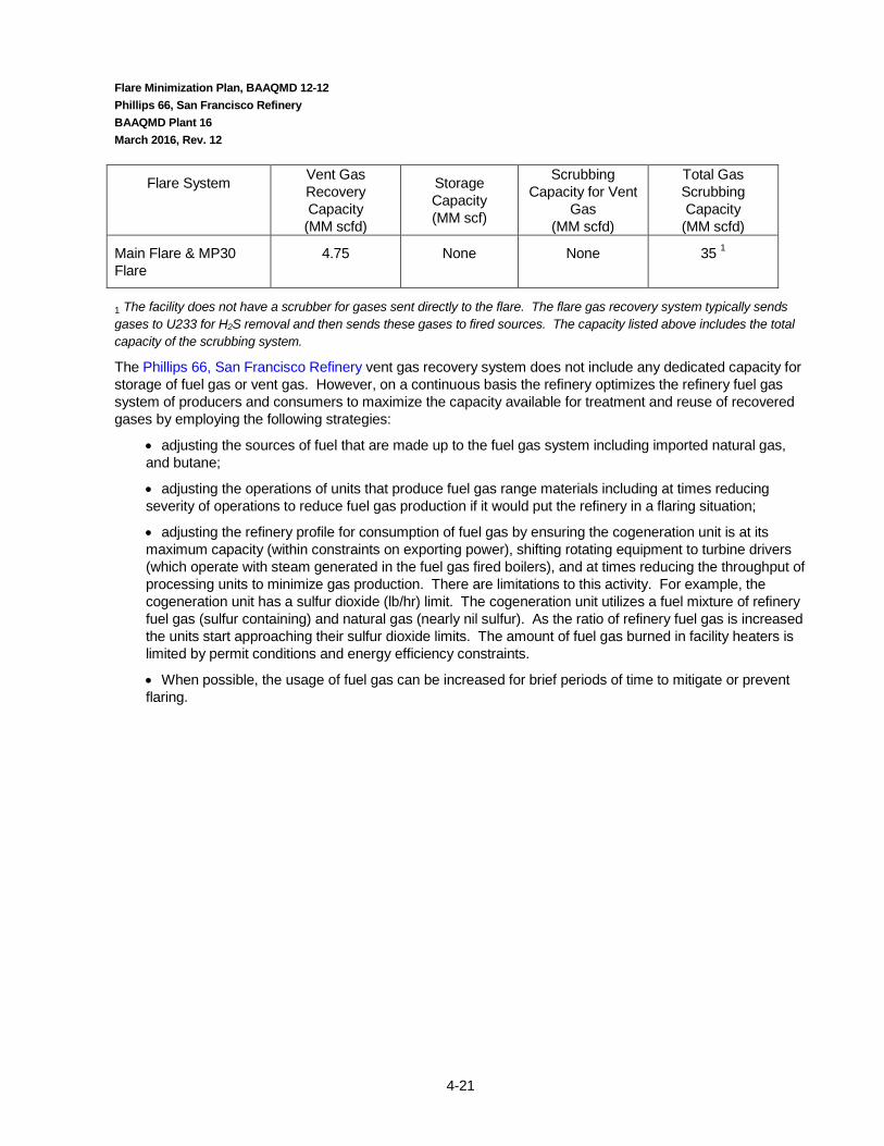
Flare Minimization Plan, BAAQMD 12-12 Phillips 66, San Francisco Refinery BAAQMD Plant 16 March 2016, Rev. 12
4-21
Flare System
Vent Gas Recovery Capacity (MM scfd)
Storage Capacity (MM scf)
Scrubbing Capacity for Vent
Gas (MM scfd)
Total Gas Scrubbing Capacity (MM scfd)
Main Flare & MP30 Flare
4.75 None None 35 1
1 The facility does not have a scrubber for gases sent directly to the flare. The flare gas recovery system typically sends gases to U233 for H2S removal and then sends these gases to fired sources. The capacity listed above includes the total capacity of the scrubbing system.
The Phillips 66, San Francisco Refinery vent gas recovery system does not include any dedicated capacity for storage of fuel gas or vent gas. However, on a continuous basis the refinery optimizes the refinery fuel gas system of producers and consumers to maximize the capacity available for treatment and reuse of recovered gases by employing the following strategies:
• adjusting the sources of fuel that are made up to the fuel gas system including imported natural gas, and butane;
• adjusting the operations of units that produce fuel gas range materials including at times reducing severity of operations to reduce fuel gas production if it would put the refinery in a flaring situation;
• adjusting the refinery profile for consumption of fuel gas by ensuring the cogeneration unit is at its maximum capacity (within constraints on exporting power), shifting rotating equipment to turbine drivers (which operate with steam generated in the fuel gas fired boilers), and at times reducing the throughput of processing units to minimize gas production. There are limitations to this activity. For example, the cogeneration unit has a sulfur dioxide (lb/hr) limit. The cogeneration unit utilizes a fuel mixture of refinery fuel gas (sulfur containing) and natural gas (nearly nil sulfur). As the ratio of refinery fuel gas is increased the units start approaching their sulfur dioxide limits. The amount of fuel gas burned in facility heaters is limited by permit conditions and energy efficiency constraints.
• When possible, the usage of fuel gas can be increased for brief periods of time to mitigate or prevent flaring.
Flare Minimization Plan, BAAQMD 12-12 Phillips 66, San Francisco Refinery BAAQMD Plant 16 March 2016, Rev. 12
4-22
4.2.2.1 Options for Recovery, Treatment and Use
To address the requirements of Regulation 12 Rule 12 (401.4), the Phillips 66, San Francisco refinery at Rodeo, CA has considered the feasibility of further reducing flaring through additional recovery, treatment, and/or storage of flare header gases, or to use the recovered gases through other means. This evaluation considers the impact these additional systems would have on the volume of flared gases remaining in excess of what has already been recovered (as noted in the previous section), and the associated mass flow of hydrocarbons emitted after combustion in the flare control device.
A typical flare header is connected to both a flare gas recovery system and to one or more flares. Normally all vapor flow to the flare header is recovered by a flare gas recovery compressor, which increases the pressure of the flare gas allowing it to be routed to a gas treater for removal of contaminants such as sulfur and then to the refinery fuel gas system. Gas in excess of what can be handled by the flare gas recovery compressor(s), the treater(s), and/or the fuel gas system end users flows to a refinery flare so it can be safely disposed of by combustion. Therefore, in order to reduce the volume of gas flared, three essential infrastructure elements are required: sufficient compressor capacity to increase the pressure of the gas to the point where it can be used in the refinery fuel system, sufficient storage volume to dampen out the variation in volumetric flowrate to the flare gas header, and sufficient capacity in treating systems to condition the gas (primarily by removal of sulfur) for use in the fuel gas system.
Options for storage of flare gas are analogous to those for storage of other process gases. Gases can be stored at low pressure in expandable gas-holders with either liquid (water) or dry (fabric diaphragm) seals. The volumes of these systems expand and contract as gas is added or removed from the container. Very large vessels, containing up to 10,000,000 cubic feet of gas can be constructed by using multiple “lifts”, or stages. Gases can also be stored at higher pressures, and correspondingly lower volumes, in steel bullets or spheres. The optimal pressure vessel configuration depends on system design pressure and total required storage volume.
For any type of gas storage facility, selection of an acceptable site and obtaining the permits necessary for construction both present difficulties. Despite the refinery’s demonstrated commitment and strong track record with respect to safe handling of hazardous materials, the surrounding community can be expected to have concerns about any plan to store large volumes of flammable gas containing hydrogen sulfide and other sulfur compounds. Safety concerns are expected to impact site selection as well, with a relatively remote location preferred. Modifications to the recovery, storage and treating of refinery flare gases are subject to the provisions and approval of federal and local regulations including Process Safety Management (PSM), Contra Costa County Industrial Safety Ordinance (ISO), and California Accidental Release Prevention Program (CalARP). Although the objective of the project would be a reduction in flaring, there are expected to be multiple hurdles along the path to a construction/land use permit.
Flare gas treating is used to condition flare gas for use as fuel in the refinery fuel gas system. Treatment is focused on removal of sulfur compounds, with some systems improving fuel value by removing carbon dioxide as well. A range of technology options exist, most of which are based on absorption of acid gases into a “lean” amine solution (MEA, DEA, MDEA, DGA) with regeneration of the resulting “rich” solution by stripping at lower pressure. In order to recover additional fuel gas it is necessary to have sufficient capacity to match the capacity of gas treating systems to the peak flowrate of the flare gas requiring treatment.
In order to assess the potential effect of additional flare gas recovery, a hypothetical design for an upgraded system was developed. The impact that this system would be expected to have on hydrocarbon emissions, based on the refinery’s recent flaring history, was then evaluated. Results of this evaluation are provided for three system capacities corresponding to the rate of flow of additional flared gases that could be recovered, the modifications required to achieve that recovery, and the estimated total installed cost for the additional equipment needed for the increase in recovery. The budgetary level (order of magnitude) cost information

Flare Minimization Plan, BAAQMD 12-12 Phillips 66, San Francisco Refinery BAAQMD Plant 16 March 2016, Rev. 12
4-23
provided in this section has been developed based on total installed cost data from similar installations where available, otherwise vendor quotes in combination with standard industry cost estimation procedures have been used to estimate system cost.
An evaluation was conducted for the Phillips 66, San Francisco Refinery in Rodeo, CA. In order to conduct the analysis a summary of historical flaring was prepared. Flaring events were categorized in order to determine feasible means for reducing flaring through storage, recovery, and treatment. See Attachment H for summary of categorized, historical flaring. The period of 2004 – 2006 was utilized to determine general trends. The data for 2005 was utilized to quantify potential costs and benefits of additional storage, recovery, and/or treatment.
Based on the data review it was determined that four cases should be examined. The cases include the following scenarios:
• Case 1 – Installation of Small Compressor (1.5 MMSCF/day) to enhance existing compressor recovery during peak loading.
• Case 2 – Installation of Large Compressor (6.0 MMSCF/day) to eliminate minor compressor loading events and some flaring events which occur during brief Flare Gas Recovery Compressor (G-503) preventative maintenance periods.
• Case 3 – Installation of high pressure storage sphere, installation of large compressor, and addition of amine treater. Value of this case would be to eliminate all events listed in Case 2 as well as some events which are quality driven (e.g. high Nitrogen & Hydrogen) due to equipment purging.
• Case 4 – Similar to Case 3 with a higher percentage of the volume generated during the quality driven flaring events would be eliminated.
See Attachment I for example schematic of the equipment installations that would be involved in Case 3 and 4.
Listed below is a summary of the overview of the analysis performed and the results of the analysis.
Storage, Treatment, & Recovery Scenario - Emission Reduction & Cost Effective Analysis
Estimated Potential Reductions (tons/yr) Cost Effective
Basis (tons)
Cost of Control ($MM)
Annualized Cost of
Abatement System ($MM)
Cost Effectiveness Basis ($/ton)
Case VOC SO2 Nox CO PM
1 -0.15 -0.62 -0.02 -0.19 negligible -0.98 $ 3.25 $ 1.06 $ (1,084,092)
2 -1.12 -4.51 -0.13 -1.38 -0.01 -7.16 $ 7.50 $ 2.51 $ (350,420)
3 -1.57 -6.35 -0.19 -1.94 -0.02 -10.07 $ 23.40 $ 6.19 $ (615,476)
4 -2.02 -8.18 -0.24 -2.51 -0.02 -12.97 $ 23.40 $ 6.19 $ (477,509)

Flare Minimization Plan, BAAQMD 12-12 Phillips 66, San Francisco Refinery BAAQMD Plant 16 March 2016, Rev. 12
4-24
1 Basis is BAAQMD Guidelines for calculation of cost-effectiveness for BACT using the “levilized cash flow method”. Costs for equipment were based on cost curves developed by a third-party.
It should be noted that the cost basis did not include the consideration of infrastructure adequacy and did not include all potential equipment and instrumentation necessary. It is expected that once a more rigorous evaluation is performed the costs will significantly be impacted. For example, the cost of infrastructure needs for equipment utilizing electricity and air is expected to be significant. Attachment N contains data utilized to calculate the cost effectiveness of the four cases described above. The storage sphere costs were based on quotes provided by Chicago Bridge and Iron and are contained in the Attachment. A cost curve was prepared by a third-party for the compressor costs. The costs were based on data points of actual costs provided by WSPA membership.
For Case 3 and 4, the evaluation is based on the need for installation of new major systems in order to increase recovery of flare gases from current levels:
• Additional flare gas recovery compressor capacity - the estimated cost to provide additional compressor capacity to recover vent gas flowing in the flare header in excess of current compressor capacity, for transfer to storage and / or treatment. Costs provided are for one unspared compressor system to be added to one existing flare header. The estimate is for a reciprocating compressor with all necessary appurtenances for operation, including knock out pots, coolers, and instrumentation for a fully functional system.
• Addition of surge volume storage capacity – the estimated cost to provide temporary surge storage for a portion of the gases routed to the flare header in excess of the volumes currently being recovered, treated, and consumed. The addition of temporary surge storage volume is necessary for any further increase in flare gas recovery to allow flare gas flow (which is highly variable) to be matched to the demand for fuel gas. The cost used is based on a storage volume equal to the total volume of gas accumulated over one day, and is based on recovery in a high pressure sphere system with discharge at a controlled rate back to the flare gas header. Other lower pressure approaches were considered (low pressure gas holder, medium pressure sphere), but for the sizes analyzed a high pressure sphere was identified as the preferred approach based on operational, safety and economic considerations.
• Additional recovered gas treatment capacity – the cost of additional amine-based treating capacity to process recovered gases for sulfur removal so that they can be burned by existing fuel gas consumers without exceeding environmental or equipment operational limits. The assumption is that for small increases in treating capacity the existing treater(s) will be modified / upgraded to allow for the increase. No additional cost has been included for expansion of sulfur recovery system capacity.
Based on this review the Phillips 66, San Francisco Refinery has concluded that further expansion of systems for the recovery, treatment and use of flared gases is not the most effective approach to reducing these emissions. The refinery has concluded that the major source of flared gases on a volume basis can be attributed to large flow rate, low quality flaring events, especially those of extended duration such as may occur during emergency events or prolonged shutdowns where systems within the refinery are out of fuel gas (and / or hydrogen) balance.
The refinery has allocated significant resources to the development of procedures to plan for, manage, and minimize large flow and duration flaring events. Further resources have also been allocated effectively to ongoing preventive maintenance programs, and even to adjust refinery operations on a severity and throughput basis. These approaches have been identified to be more effective than providing additional flare gas recovery system capacity. Additionally, it is expected that the practices discussed in this plan, specifically the development of a formal turnaround flare management procedure, continuation of incident investigations,

Flare Minimization Plan, BAAQMD 12-12 Phillips 66, San Francisco Refinery BAAQMD Plant 16 March 2016, Rev. 12
4-25
and management system programs will result in further reductions of flaring events. These will likely prove to be most cost effective and meaningful.
4.2.2.2 Preventing Production of Low-Quality Flare Gas
Measures to help prevent production of low-quality flare gas, e.g. sour gas, low Btu gas, high nitrogen content are further investigated in this section. The discussion is integrated with the discussion of turnaround and maintenance events as gas quantity (insufficient demand) and gas quality (unscrubbed during upset/malfunction and nitrogen/steam during turnaround) are the primary drivers for flaring during these events. It is for this reason that the measures used to minimize production of low quality fuel gas are closely related to those that can be applied to reduce flaring during maintenance and turnaround events.
Preventing production of sour flare gas is accomplished by making sure that recovered flare gas is routed to the fuel gas system via a gas treating system. It is preventing the production of sour fuel gas that drives the need to match the capacity of treating systems to accept flare gas to flare gas recovery capacity.
High fuel gas nitrogen levels are primarily caused by the nitrogen used to purge hydrocarbons from equipment in preparation for equipment opening. High nitrogen fuel gas content is controlled by limiting the rate at which nitrogen is introduced to equipment and ultimately the flare gas system during nitrogen purging operations. There can be a trade-off between nitrogen flowrate and the effectiveness with which the nitrogen mixes within the contents of the vessel from which hydrocarbons are being removed. These must be balanced on a case-by-case basis to determine the purge rate that represents the best compromise among competing process needs. Scheduling decommissioning activities to minimize overlapping nitrogen purge events is one of the best ways to control the nitrogen content of flare gas.

Flare Minimization Plan, BAAQMD 12-12 Phillips 66, San Francisco Refinery BAAQMD Plant 16 March 2016, Rev. 12
4-26
4.3 Recurrent failure (401.4.3) − of Pollution Control Equipment − Process Equipment, or − A process to operate in a normal or usual manner:
4.3.1 Reportable Flaring Events Attributable to the Same Process or Equipment Item For the Period from June 30, 2010 to June 30, 2015
A discussion and analysis of each event, including actions taken to avoid future flaring as a result of the same cause and the adequacy of maintenance schedules and protocols. Flaring as the result of malfunctions and upsets is included in the analysis. Attachment H contains a listing of the reportable events and the associated corrective actions.
Reportable Flaring Events Attributable to the Same Process or Equipment Item
Date Process or Equipment Item Actions Taken to Avoid Future Flaring
1/18/12 Air Liquide removal of RFG A from process feed to change feed gas coalescer filter.
Third party Hydrogen Plant installed a tie in for potential future additional water filter.
Temporary piping to blow down was added for the bleed at the low point in the RFG A gas line prior to going to Air Liquide.
Phillips 66 communicated with Air Liquide regarding the filter replacements. Phillips 66 and Air Liquide discussed having better communication prior to Air Liquide conducting the filter replacements and notifying appropriate refinery personnel so that flaring can be minimized or eliminated.
Since the incident on 9/30/14, Air Liquide has replaced the filters without another flaring RCA being triggered.
3/26/12
9/30/14
1/25 – 2/4/15
Equipment inappropriately sized or installed at Unit 246 G-802 Hydrogen Gas Recycle Compressor.
Replace 0.5 amp fuse with 2.0 amp fuse associated with the solenoid valve that maintains oil pressure on the G-802 trip and throttle valve (Gimpel valve). Review all other fuses associated with this control system and panel for proper sizing. Replace improperly sized fuses as necessary.
Write a checklist procedure for dry gas seal installation on the U246 G-802 seals. Procedure should call out the appropriate seal drawing and require a craftsperson to mark each step as completed. This checklist will include all major components to install the seals including the socket head screws that were inadvertently omitted prior to the February 4th startup attempt.
Conduct refresher training on Maintenance Procedure (MP) 2.53, Safe Assembly of Tubing Connections Guideline, with P66 and contractor instrument technicians, pipe fitters and machinists.
Audit training records for those performing instrument tubing assembly per MP 2.53 requirements.
2/4 – 2/5/15
2/14/15
4.3.2 Means to Prevent Recurrent Failure
There are many programs in place in order to prevent recurrent failures. The programs fall into two major categories; proactive and reactive. The purpose of the proactive programs is to have systems in place based on potential failures that could occur in order to prevent failures from occurring. The reactive programs

Flare Minimization Plan, BAAQMD 12-12 Phillips 66, San Francisco Refinery BAAQMD Plant 16 March 2016, Rev. 12
4-27
examine failures that have occurred in order to learn from the failure and develop stronger proactive programs to prevent recurrence. The facility employs many levels of proactive and reactive programs.
4.3.2.1 Proactive Programs
BAAQMD Regulation references “the adequacy of existing maintenance schedules and protocols” for air pollution control and process equipment in respect to recurrent failures. There are major programs in place which support the prevention of failures. Additionally, these programs facilitate continuous improvement to prevent failures. Key programs in place are described below.
Phillips 66 HSE Management System
Phillips 66 Corporation requires each refinery to implement a standard Health, Safety, and Environmental (HSE) Management System. This is achieved through providing organization structure, programs, procedures, processes, and resources to manage business activities safely and with respect and care for the environment. The HSE Management System seeks to:
• Demonstrate management commitment to health, safety, & environmental stewardship.
• Ensure that all reasonably practicable steps are taken to identify the hazards and risks arising from business activities.
• Establish adequate control over business activities with the aim of achieving safe, incident, and injury free working conditions.
• Maximize the operational integrity, reliability, and efficiency.
• Ensure regulatory compliance.
• Promote high standards and the continuous improvement of HSE performance.
Process Safety Management (PSM)
The refinery must comply with EPA’s PSM. Major elements of PSM are also incorporated in California’s Accidental Release Prevention Program (CalARP), the Contra Costa County (CCC) Industrial Safety Ordinance (ISO) and EPA’s Risk Management Program. There are fourteen elements of PSM, each of these elements is included in some fashion with the programs listed above. In addition, the CCC ISO and CAL ARP program have some additional elements. Although all the elements directly or indirectly prevent failures or minimize the impact of a failure if it occurs, listed below are some of the programs that most directly support failure prevention.
Employee Participation – Employees at all levels must be involved with the elements of PSM. This encourages ownership, participation and buy-in of incident investigation results and means for improvement, and promotes a better safety and operating culture.
Process Safety Information (PSI) – the refinery is required to maintain accurate Process Safety Information. PSI includes chemical inventory, accurate drawings, operating procedures, etc.
Process Hazards Analysis (PHA) - A PHA is a systematic evaluation of the hazards involved in the process. PHAs are required for initiation of a process and at least once every five years after that. The PHA team should be multi-disciplinary, including maintenance, operations, and engineering. The facilitator of the PHA must be trained in the methodology being used. For proper conduct of a PHA,

Flare Minimization Plan, BAAQMD 12-12 Phillips 66, San Francisco Refinery BAAQMD Plant 16 March 2016, Rev. 12
4-28
the PSI must be as complete as possible. One of the values of PHA’s is to identify potential hazardous and develop means for mitigating hazardous before they occur.
Operating Procedures - Operating procedures include not only the steps for normal operations, but for upset conditions, temporary operations, start-up, and shutdown. Very important safety information must also be included in operating procedures. Contained in the procedures are basic hazards of exceeding operational limits, appropriate response to upset conditions, safety and health information, and emergency operations. The procedures are required to be up to date and reliable. They are also a critical element in training of personnel.
Training - Training is required for all employees new to a process before they become involved in that process. The training must include the hazards of the chemicals and process and what is necessary to protect themselves, their fellow employees, and their surrounding communities. Training should be both written/classroom and hands-on. Employers must evaluate the effectiveness of training and make adjustments to content and frequency of training based on those evaluations.
Pre-Startup Safety Review (PSSR) - The Pre-Startup Safety Review is done before startup of a new operation or startup following a change in the process (see Management of Change, below). It is a means for ensuring that all essential action items and recommendations from the PHA have been completed prior to beginning operations. It is also the point at which the design parameters and standards used for construction are verified. If training or modifications to Process Safety Information (PSI) are necessary, completion of these items is also verified during the PSSR. Startup should not be allowed to occur until all safety-critical PSSR items have been completed.
Mechanical Integrity - Employers are required to have a program to ensure the integrity of processes and equipment. Aspects include listing applicable equipment, training of maintenance personnel, inspection and testing, and maintenance of such systems as controls, vessels, piping, safety systems, and emergency systems. Development and modifications to the mechanical integrity program should be made based on operational experience, relevant codes, and industry standards.
Management of Change (MOC) - “Change” includes anything that would require a change in Process Safety Information. This includes changes to equipment, processes, and instrumentation. A proper MOC system requires that any change be evaluated prior to its implementation. The level of evaluation can depend on the degree of change and its criticality to the safety of the operation. In addition to the evaluation and approval of a change, MOC requires that suitable training be conducted (if necessary) and the relevant PSI be updated.
Compliance Audits - Per OSHA, compliance audits must be conducted at least once every three years. The purpose of the audits is to determine whether the practices and procedures developed under the provisions of the PSM standard are being followed and are effective. The auditor(s) must be knowledgeable in PSM and should be impartial to the facility being audited. An audit report must be developed and the employer must promptly respond to each of the findings. Once deficiencies are corrected, the corrective action must also be documented.
Maintenance Excellence Philosophy
Predictive Maintenance - The Rodeo Refinery utilizes predictive maintenance tools for both rotating equipment (pumps, blowers, fans, motors) and fixed equipment (pressure vessels, piping, storage tanks). These tools can be used to predict equipment condition and failures so that appropriate preventive measures can be taken, or so repairs can be scheduled prior to a failure. The Rotating Equipment/Reliability Department is responsible for ensuring that rotating equipment is in good condition and the Metallurgical Engineering and Inspection (ME&I) department is responsible for inspecting fixed equipment in the facility.
ROTATING EQUIPMENT

Flare Minimization Plan, BAAQMD 12-12 Phillips 66, San Francisco Refinery BAAQMD Plant 16 March 2016, Rev. 12
4-29
The following is a list of tools and techniques used for maintaining the rotating equipment: Operator Inspections/Seal Integrity Equipment Deficiencies Vibration Analysis Lube Oil Testing Overhaul Testing Operator Inspections / Seal Integrity
Operators visually inspect the equipment case and seal/packing area for signs of leakage. Mechanical seals are the number one failure mode in centrifugal pumps. Operations and maintenance personnel include visual monitoring of seals in their shift rounds. In some cases, for example where dual seals are installed, instrumentation (level, pressure, etc.) is available to alert operations that action is required. Seals subject to LDAR (Leak Detection and Repair) regulations are monitored for hydrocarbon emissions on a regular basis.
Operators listen to and observe the equipment operation to detect any unusual noises and/or vibrations that may indicate damage or wear.
Equipment Deficiencies
If a potential deficiency is observed, the operator contacts the Operations Supervisor to request consultation by the appropriate craft or by the Rotating Equipment Group. If it is determined that repair is required, the operator submits a Work Request via the Computerized Maintenance Management System and initiates the steps necessary to make the equipment available for repair. The Work Request documents the deficiencies noted during the operator inspection.
Vibration Analysis Vibration analysis can be a useful predictive maintenance activity to identify potential equipment failures so that proper maintenance can be scheduled before a failure occurs. Vibration readings are taken using hand-held piezoelectric accelerometers. Readings are normally taken on all bearing planes (horizontal, vertical, axial). Local panel readings for vibration and temperature, where applicable, are also entered into the data collector. The data is then typically uploaded into the vibration analysis computer, which can be compared to historical data, industry guidelines, or vendor data to assist in scheduling maintenance or indicating the need for additional detailed analysis. Rodeo Refinery personnel participate on a Phillips 66 Rotating Equipment Best Practices Network to facilitate learning in this area. Lube Oil Testing
Several pieces of rotating equipment are classified as critical. A sample of lube oil is drawn from the appropriate critical equipment, or other machinery of interest, quarterly or as warranted. This sample is sent to a certified laboratory for a standard set of analyses. The results are transmitted to the Machinery Specialist. The results of each analysis are entered into a computer database as a single record. The data included in the record are:
• Equipment tag number • Date of sample • Analysis results

Flare Minimization Plan, BAAQMD 12-12 Phillips 66, San Francisco Refinery BAAQMD Plant 16 March 2016, Rev. 12
4-30
Sample test results are trended and compared to established limits of operation for each specific piece of equipment. If a deficiency is noted, the Machinery Specialist initiates an appropriate corrective action. These could include continued monitoring, oil replacement, filtration, or a repair of the equipment.
Overhaul Inspections
Equipment that has been removed to the shop for repair undergoes a detailed internal inspection to identify wear or damage that could affect performance or mechanical integrity. Machinists perform visual inspections and measure clearances for comparison to manufacturer's specifications. If necessary, the Inspection Group can perform more sophisticated tests (radiographs, ultrasonic, magnetic particle, liquid penetrant and materials analysis) if requested by the Rotating Equipment Group or Maintenance.
FIXED EQUIPMENT The Rodeo Refinery utilizes the following techniques to ensure fixed equipment is in good condition:
• External Visual Inspection, • Internal Visual Inspections, and • Thickness Surveys.
External Visual Inspection The primary reasons for performing external visual inspections of pressure vessels, piping and storage tanks are to determine the type, rate and causes of any deterioration present that may negatively affect their mechanical integrity and/or service performance and to determine if any maintenance work is required to maintain the equipment in a safe operating condition.
External visual inspections are performed by qualified Phillips 66 or contract inspectors. The external visual inspection results are documented in an external inspection report. The report is completed and dated by the inspector(s) performing the external visual inspection. It is reviewed by the plant’s Inspection Supervisor or authorized representative. The completed report is filed in the equipment inspection history file located in the plant’s Inspection Department. Internal Visual Inspection The primary reasons for performing an internal visual inspection are:
1. to determine if the essential sections of the vessel are safe to operate until the next inspection;
2. to determine the type, rate and causes of any deterioration present which may negatively affect its mechanical integrity; and,
3. to determine if any maintenance work is required to maintain the pressure vessel in a safe operating condition.
The internal visual inspections are performed by qualified Phillips 66 or contract inspectors. Pressure vessels are typically visually inspected internally at least once every 10 years, in accordance with API standards. Non-fired boilers are inspected every 6 years maximum and fired boilers are inspected every 3 years maximum, in accordance with State of California requirements. In practice, many vessels and heaters in sulfur plants are visually

Flare Minimization Plan, BAAQMD 12-12 Phillips 66, San Francisco Refinery BAAQMD Plant 16 March 2016, Rev. 12
4-31
inspected internally during a boiler inspection period, at a 3, 6, or 9 year interval and therefore, well within the 10 year maximum interval allowed by API industry standards. The inspection results are documented in an internal inspection report. The report is completed and dated by the inspector(s) performing the internal visual inspection. It is reviewed by the plant’s Phillips 66 Inspection Supervisor or authorized representative. The completed report is filed in the equipment inspection history file located in the plant’s Inspection Department. Thickness Survey A representative number of thickness measurements are taken on pressure vessels via ultrasonic and/or radiographic thickness techniques for remaining wall thickness at intervals pre-established by the industry. Thickness surveys are also performed on most process piping runs. The thickness survey is prompted by the plant’s Inspection Department to meet all requirements for thickness surveys as outlined in the applicable API standard. The thickness surveys are performed by qualified Phillips 66 or contract inspectors who have the appropriate education, experience and qualifications. The general area of each thickness monitoring location (TML) is ultrasonically scanned and/or radiographed and the lowest reading is recorded. When using ultrasonics, scanning the general area rather than monitoring the same exact location increases the chance of finding local corrosion and typically yields a larger (more conservative) general corrosion rate. The thickness survey results are completed and dated by the inspector(s) performing the thickness survey. It is reviewed by the Phillips 66 site Inspection Coordinator or authorized representative. The completed report is filed in the appropriate equipment file and all data is recorded in an electronic database (PCMS System).
Preventive Maintenance - Preventive maintenance activities ensure that equipment and instrumentation function properly through their design life. Examples of these activities are outlined below. Deficiencies are corrected at the time of the inspection where possible or work orders are written to facilitate cleaning or repair.
Instrumentation Instruments that are critical to unit operations are reviewed and calibrated and cleaned as needed. Examples include flow meters, fire eyes, temperature monitoring devices and analyzers used for performance monitoring and control. Plant performance testing, through pressure surveys, temperature indicators, efficiency calculations or other data collection is used to resolve discrepancies in measurement devices. Rotating Equipment To ensure reliable operation of rotating equipment, spare equipment can be operated, where installed, to facilitate repair. Seals and bearings are replaced based on inspections or predictive maintenance activities. Preventive maintenance tasks include cleaning, adjustment, and lubrication. Operators replace lubricating oil and grease on a frequency set by a master schedule for the Refinery. Appropriate lubricants are specified in a written plan. Steam turbine drivers’ over-speed trip protection devices are tested at an established frequency. Fans and mixers are cleaned, lubricated and tested.

Flare Minimization Plan, BAAQMD 12-12 Phillips 66, San Francisco Refinery BAAQMD Plant 16 March 2016, Rev. 12
4-32
Fixed equipment Thickness measurements and corrosion monitoring (probes, coupons, external UT, and critical process variables) are used to schedule preventive maintenance on vessels. Refurbishment of steel through weld buildup, plate replacement, coatings, or vessel replacement is used to ensure the mechanical integrity of pressure vessels. Refractory is replaced based on inspections, monitoring skin temperatures and thickness in fired equipment and based on internal visual inspections of refractory condition. Jacketing/Tracing Integrity of steam and electric tracing used in sulfur processing units is verified through regular plant walkthroughs/checklists by plant operations and maintenance personnel.
Catalyst & Chemicals Unit catalyst and chemical activity is monitored by unit engineers and operators through pressure surveys and temperature indicators. Lab testing is conducted on intermediate and products to monitor quality. When quality is compromised, operational parameters or other means are employed to ensure continued performance.
Turnaround Inspection And Repair - Major maintenance turnarounds of the process and utility units are planned based on predictive/preventative maintenance activities. Prior to each planned shutdown, a work scope is developed for detailed inspection, repair, replacement and testing of equipment, catalyst and chemicals to ensure the unit will operate properly until the next planned shutdown. The exact activities for each planned shutdown are determined by Operations, ME&I, Engineering, Reliability and Maintenance personnel prior to each shutdown. A criticality ranking process is used to determine which proposed work activities are included in the turnaround inspections and repairs. Where practical, maintenance is performed on the equipment while the unit is still in operation. Typical turnaround activities include cleaning equipment, replacing/rejuvenating catalyst and chemicals and inspecting/repairing/replacing equipment as-needed.
Flare Minimization Plan, BAAQMD 12-12 Phillips 66, San Francisco Refinery BAAQMD Plant 16 March 2016, Rev. 12
4-33
Critical Instruments & Safety Instrumented System
The facility has a list of critical devices and has a procedure for handling Safety Instrumented Systems. Safety Instrumented Systems (SIS) take processes to a safe state when predetermined conditions are exceeded. This includes set points such as pressure, temperature, level, etc. These programs maintain the reliability of such devices and systems in order to ensure that shutdown systems have been appropriately established and are reliable.
Near Miss/Good Catch Program
A process is in place that encourages all employees to identify and report potential near misses. Near misses are undesired events which, under different circumstances, could have resulted in harm to people, damage to property or the environment, or production/business loss. Near misses may also include unsafe practices, acts or conditions. The value of this program is that it facilitates:
• Identifying and addressing safety, procedural, environmental impact, design or equipment issues in a proactive, non-threatening manner.
• Identifies learning or training opportunities.
• Sharing of “lessons learned” and best practices with other employees and facilities.
Solomon Refining Comparative Analysis
The refinery participates in periodic comparative analysis. Flare volumes are one of the parameters included. Flare volumes are included in the metric to examine materials that could have been recovered from an economic standpoint. The purpose of the analysis is to determine how facilities compare with their peers in critical parameters.
4.3.2.2 Reactive Programs
When a failure has occurred, depending on the magnitude of a failure, the event will be examined in further detail. Listed below is an overview of the major elements of the programs in place to prevent recurrence of failures.
Incident Investigation An internal procedure is in place which identifies the type of failures which require incident investigation. This process is a key part of our Health, Safety, and Environmental Management System. Failures captured by this process typically include accidents, injuries, events with potential off-site impact, some levels of flaring events, upsets which result in business loss. The procedure requires that an investigation be conducted and corrective actions identified. The regulatory drivers for this program include, but are not limited to; EPA’s PSM, EPA Risk Management Program, Contra Costa County (CCC) Industrial Safety Ordinance (ISO), California’s Accidental Release Prevention Program (CalARP). Additionally, there are strong business case drivers for completing incident investigation and preventing recurrence.
Root Cause Reporting In addition to the incident investigations described above, root cause is required to be reported for higher level events based on various regulatory drivers. Regulatory drivers include but are not limited to; BAAQMD regulations 12-11 & 12-12, EPA SARA/CERCLA reporting requirements, Phillips 66 EPA Consent Decree requirements, Contra Costa County ISO.

Flare Minimization Plan, BAAQMD 12-12 Phillips 66, San Francisco Refinery BAAQMD Plant 16 March 2016, Rev. 12
4-34
Flare Monitoring & Reporting Procedure The procedure documents the BAAQMD monitoring and reporting requirements. Additionally, it contains levels in which flare incident investigations must be conducted. The levels correspond to those required by BAAQMD and in the Phillips 66 Consent Decree. See Attachment E for general overview of the process for reviewing flaring events. Use of Incident Investigation Documentation Software Phillips 66 requires use of a Corporate wide software tool in which certain risk levels of incidents must be tracked. An overview of the incident is included in the software as well as the corrective actions. Depending on the level of the incident, the overview of the incident is immediately shared with Vice President level staff electronically via the software. High Learning Value Event (HLVE) If an event occurs in which a lesson learned might have value to sister refineries within Phillips 66 a system has been established for quickly sharing lessons learned so that other facilities may not experience a similar incident. Corporate Incident Notification Requirements Higher level events, such as off-site impacts, require immediate notification to the Corporation.
Corporate Health, Safety, and Environmental Reporting Requirements
Flaring volumes are required to be reported and are tracked refinery by refinery to the Corporation on a regular basis.
Key Performance Indicators (KPIs) -
KPIs are reported internally throughout the facility on a periodic basis. The KPIs include the number and cause of flaring events. The purpose is to inform plant personnel of occurrences of these events and to encourage continuous improvement by tracking cause and number.
Regulatory Notifications
There are various regulatory drivers which require notification of various levels of flaring events. Drivers include; BAAQMD 12-12, EPA’s SARA/CERCLA, CCC Community Warning System requirements, etc.

Flare Minimization Plan, BAAQMD 12-12 Phillips 66, San Francisco Refinery BAAQMD Plant 16 March 2016, Rev. 12
5-1
5.0 Other Information Requested by APCO to Assure Compliance (401.5)
5.1 New Equipment Installations (404.2) No other information has been requested by the APCO.

Flare Minimization Plan, BAAQMD 12-12 Phillips 66, San Francisco Refinery BAAQMD Plant 16
ATTACHMENT A
SAN FRANCISCO REFINERY
SIMPLIFIED FLARE SYSTEM OVERVIEW

Process Gas From MP-30 Complex
Process Gasfrom MP-30
Purge (Natural Gas) Purge (Natural Gas)
42'' Line Flow Meter
Purge (Natural Gas)
48" Line Flow Meter
Main FlareC-1
MP-30 FlareC-602
Process GasFrom Refinery
Blowdown
AI 586
AI 520
AI 584
U-233
TreatedFuel Gas
Unit Heaters & Cogen
F-3
UnicrackerBlowdown
U200/267Blowdown
Attachment A San Francisco Refinery
Simplified Flare System OverviewPurge (Natural Gas)
WaterSeal Water
Seal
Fuel Gas Center
(H2S Removal)U 200 Wet Gas (G-501) Compressor
Odor Abatement Compressors
UK / MP30 Sour Gas
10'' Line Flow Meter
G-540 Liquid Ring Flare GasRecovery Compressor (New 2009)
A
B
CG-503 Flare Gas
Recovery Compressor
WaterSeal
AI 585
36" Line Flow Meter
J. Ahlskog, 07/2008 Flare System Overview...vsd
Flare Minimization Plan, BAAQMD 12-12 Phillips 66, San Francisco Refinery BAAQMD Plant 16
ATTACHMENT B
Phillips 66
San Francisco Refinery, Rodeo, CA
Flare Gas System Detailed Description
Listed below is a detailed overview of the facility flare system. Although some parameters are contained in this description they are subject to change as operational or safety enhancements are identified.
The Refinery Relief and Blowdown Systems provide a means for recovery or safe disposal of gases and liquids, which may be generated by the process units. Typical sources of normal flow include coke drum steamout and switching, sampling, activation of relief valves, distillation tower overhead vapors, and purging of equipment for maintenance or startup. During emergencies, major flow may occur from heater or unit depressuring and the lifting of pressure relief valves. Gases and liquids flow through relief and blowdown lines to blowdown accumulators and knockout drums. Gases and vapors pass overhead to be recovered or flared. The liquids are generally reprocessed through appropriate operating units.
There are two flares in the refinery – the Main Flare and MP-30 Flare. There are three relief and blowdown systems; the Refinery, the Hot Coker Blowdown, and the MP-30 system. Typically the gases sent to the blowdown systems are recovered, treated, and then utilized for fuel in the facility heaters and co-generation equipment. During periods when gases are not recovered, the flare gases are typically sent to the Main Flare. The Refinery and Hot Coker Blowdown system gases are routed to the Main Flare. The units located in the MP30 Complex relieve to the MP-30 Blowdown system. Typically, the gases sent to the MP-30 Blowdown System are recovered in conjunction with the gases from the Refinery and Hot Coker Blowdown system due to interconnecting piping. This interconnecting piping also accommodates minor flaring so that gases from the MP-30 Blowdown System are typically sent to the Main Flare. During major releases from MP-30, the gases would be flared at the MP-30 flare.
There are periods in which the Main Flare is shutdown in association with the Unicracker Complex shutdown. During these periods, the Refinery Blowdown system can be diverted to the MP-30 Flare. The Hot Coker Blowdown system would also be diverted to the MP-30 Flare while the Main Flare is shutdown.
Refinery Relief and Blowdown System
The Main Relief and Blowdown system handles relief and blowdown from the Coking Unit 200, Crude Unit 267, Gasoline Fractionation, Caustic Treating and Deisobutanizer Unit 215, Diesel Hydrotreating Unit 250, Steam Power Plant, Hydrogen Plant Unit 110, Fuel Gas Center Unit 233, the Unicracker Complex including Reforming Unit 244, Unit 246 Heavy Oil Hydrocracker (mid-2009), and Unisar Unit 248, Sulfur Units, Isomerization Unit 228, the Unit 120 3rd Party Hydrogen Plant (mid-2009), and minor MP-30 releases.
F-1 Blowdown Drum
Vapor and liquid releases from the units listed above flow through various blowdown headers to Refinery Blowdown Drum F-1. The Unicracker complex has its own separate Blowdown Drum F-45 upstream of F-1 to limit the liquid releases to F-1. Vapor and liquid release from the Unicracker Complex discharge into F-45. Liquids are knocked out and the vapor flows from F-45 through a 36-42″ header to F-1. Not all relief valves from the Unicracker Complex discharge to F-45. Relief valves from D-305 Fractionator discharge directly into the 36-42 ″ header from F-45.
The Steam Power Plant and Unit 110 also have separate Blowdown Drums upstream of F-1 – Blowdown Drum F-35 and Flare Knock Out Drum V-18, respectively. The sites of the Steam Power Plant and Unit 110

Flare Minimization Plan, BAAQMD 12-12 Phillips 66, San Francisco Refinery BAAQMD Plant 16
have low points in their relief headers. Liquids condensing in the SPP and Unit 110 flare headers to F-1 flow back down the flare header to their respective blowdown drums.
Entrained liquids are knocked out in F-1. At a high liquid level in F-1, blowdown pumps G-1A/1B automatically start and pump the collected liquid through Cooling Water Exchanger E-1 to the foul water tank. The foul water tank has a water phase and hydrocarbon liquid phase. The water phase is fed to the Phenolic Water Stripper D-901. The hydrocarbon liquid phase becomes feed to Coking Unit 200 or to Naphtha Hydrotreater Unit 230.
F-3 Water Seal Drum and G-503 Flare Vapor Recovery Compressor
Water Seal Drum F-3, located between drum F-1 and the Main Flare, permits the use of the blowdown system and its drums as suction surge for the G-503 Flare Vapor Recovery Compressor during normal releases. F-3 usually contains about an eight foot water seal that diverts the gas in Blowdown Drum F-1 down the main 36″ Unicracker blowdown header to the F-509 Knock Out Drum for G-503. The G-503 compressor, located in the Coker Light Ends area, returns the compressed gases to the refinery fuel gas system. The compressor design flowrate is 200,000 scf/hr of 23 MW gas. G-503 may also spare the Unit 200 G-501 Coker Wet Gas Compressor or the Unit 200 Odor Abatement compressors G-60A/B/C. When the vapor flowrate is higher than 200,000 scf/hr, vapors released to the refinery blowdown system break through the F-3 water seal and flow to the Main Flare. If the vapors released are from the MP-30 blowdown system, the vapors may also break through the F-604 water seal and flow to the MP-30 Flare. When G-503 is in G-501 or G-60A/B/C service, or G-503 is down, the F-3 water seal is removed, and vapors flow directly to the Main Flare. The F-604 water seal is not removed when G-503 is down, so that flaring of the normal releases only occurs at one flare stack.
Main Flare Header
Flare gas from D-7 Blowdown Drum and Unit 240 reactor depressuring gas release downstream of Water Seal Drum F-3. The Unit 240 reactor depressuring line bypasses drum F-1 and Water Seal Drum F-3 to accommodate depressuring of the reactors at a 300 psi/min rate. The Hot Coker Blowdown bypasses the F-3 Water Seal Drum to minimize back pressure on the Hot Coker Blowdown Drum D-7.
Any gas breaking through the F-3 water seal, vapor from D-7, and/or Unit 240 depressuring gas enter the Main Flare Stack C-1 through a water seal at the base of the flare. This seal is one of the flashback protections for the Main Flare - prevents the backflow of gas or air into the flare lines, which could create explosive mixtures. Additional flashback protections are the molecular seal and continuous purge of the flare stack. An on-line oxygen analyzer is located between F-3 and 19C-1 and sounds an alarm on high oxygen content in the Unit 200 DCS to warn operators of potentially explosive mixtures in the flare header
.Vacuum Protection for Refinery Blowdown System
After a hot vapor release through F-3, the water seal in F-3 will be automatically re-established on level control. To ensure flashback from the flare cannot occur, natural gas is added to F-1 on pressure control (PIC-530) at low pressures. The pressure indicator controller PIC-530 indicates and alarms in the Unit 200 DCS.

Flare Minimization Plan, BAAQMD 12-12 Phillips 66, San Francisco Refinery BAAQMD Plant 16
Main Flare Purge Gas Requirements
Natural gas supplies purge gas to prevent flashback. The purge gas enters the Main Flare above the water seal at the base of the flare. The molecular seal prevents both convective and diffusional backflow of air into the stack. The proprietary seal design allows some of the rising flare and purge gases to be trapped in the seal. This creates a zone, which is higher than atmospheric pressure and lower in molecular weight than air (lighter than air). Air cannot backflow through such a zone.
Main Flare Pilots
The stack tip has four electronic spark ignited pilots, each with its own ignition system. The pilots utilize electronic spark ignition for an automatic re-light function. When the thermocouple on the pilot senses a pilot outage (low thermocouple reading), the spark igniter immediately reacts to re-light the pilot. After a set period of time, the loss of pilot indication will alarm in the DCS in the Unit 200 control room. Each pilot is equipped with two thermocouples, but only one thermocouple is connected to the DCS for control of the electronic spark system. The other thermocouple is a spare.
As a back-up system to this automatic electronic spark ignition system, each pilot has a manual flame front generator line.
Temperature indicators for each pilot also alarm on low temperature in the Unit 200 DCS to alert the operators that pilot flame-out has possibly occurred. If the low temperature alarm remains on because the automatic spark ignition system has not been successful to re-ignite the pilot, an operator is then dispatched to the field to manually operate the flame front generator to re-ignite the pilot.
Smokeless Flaring at Main Flare
A small continuous flow of steam to the flare is provided to prevent a condensate build-up in the steam line and provide cooling to the flare tip. During a flaring event, additional steam is injected at the tip to aspirate air into the flame and ensure smokeless burning of the flare gases. Flow indicators, located on the two flare headers - 10″ header from D-1 and 42″ header from F-1-to the Main Flare stack- detect releases to the flare. These flow indicators also alarm in the Unit 200 DCS, so that the Unit 200 operators are aware that gas is being released to the flare. A monitor of the flare is located in the Unit 200 control room; so that the Unit 200 operators can continuously view the flare operation. If the flare is smoking, the steam flowrate to the flare tip is adjusted manually by the Unit boardman from the Unit 200 DCS. The CFEP project relief system changes are making enhancements to the steam associated with both flares to allow for higher volume flaring events to occur without resulting in a smoking flare. These enhancements will be taking place mid-2009.
MP-30 Relief and Blowdown System
When the Main Flare is in service, normally only the MP-30 Complex major releases flow to the MP-30 Flare. However, the MP-30 Relief and Blowdown System can also handle releases from Coking Unit 200, Crude Unit 267, Gasoline Fractionation, Caustic Treating and Deisobutanizer Unit 215, Diesel Hydrotreating Unit 250, Steam Power Plant, Hydrogen Plant Unit 110, Fuel Gas Center Unit 233, Sulfur Units, and Isomerization Unit 228, when the Main Flare is down for maintenance. During this maintenance period, the blowdown headers for Units 267, 200, 215, 250, 110, 233, 228, Steam Power Plant, and Sulfur Plant Complex headers can be diverted to Blowdown Drum F-2. Releases to F-2 will flow directly to the MP-30 Flare Stack
Diverting the blowdown headers to F-2 is only done, when Blowdown Drum F-1 and/or Water Seal Drum F-3 must also be inspected or repaired with the Main Flare. If F-1 and F-3 do not have to be inspected when Main Flare is down, a 26″ interconnecting line downstream of F-3 is opened to the 36″ header from F-2. This allows the refinery to keep G-503 Flare Compressor in service during the maintenance of the Main Flare and

Flare Minimization Plan, BAAQMD 12-12 Phillips 66, San Francisco Refinery BAAQMD Plant 16
minimize flaring. Only major releases will break the F-3 water seal and flow through the 26″ interconnecting line to the MP-30 Flare.
MP-30 Complex Blowdown Drum F-600
Releases from the Hydrotreating Units 229 and 230 and Reforming Unit 231 flow to Blowdown Drum F-600. Any liquid releases or entrained liquid will drop out in F-600. Liquid in F-600 gravitates to F-603 Drain Pot. On high level in F-603, blowdown pumps G-600/601 automatically start. The liquids are pumped by level control through Blowdown Slops Cooler E-600 to the foul water tank, the same foul water tank for the Refinery Relief and Blowdown System. When level in F-603 has dropped to the preset level, the pumps automatically stop.
Minor vapor releases up to 200,000 scf/hr are diverted from F-600 to the Refinery Blowdown System by a fifteen foot water seal in F-604 Water Seal Drum downstream of F-600. These minor releases flow to the Refinery Blowdown System through a 12″ cross-connecting line to the Sulfur Plant/Isomerization Unit common blowdown header. Major vapor releases break the water seal in F-604 and flow through a 42″/48″ flare header to the MP-30 Flare.
Vacuum Protection for F-600 and F-604
To prevent a vacuum, PIC-601 on F-600 adds natural gas to the MP-30 Blowdown on low pressure. In addition, the pipe entering the F-604 seal leg rises 19 feet above the top of the 15 foot water seal. Therefore, if a vacuum or partial vacuum occurs in the MP-30 blowdown system, water in F-604 will back flow up the seal pipe, but the seal will not be broken.
On low pressure in the flare header, separate pressure controller PIC-658 adds natural gas to the flare line to prevent flashback. A small continuous flow of natural gas through a restriction orifice sweeps the flare line to ensure the line does not contain any H2S, NH3, or other heavier hydrocarbons after flaring ceases.
MP-30 Flare F-2 Blowdown Drum (Partial spare for F-1)
When blowdown headers are lined up to F-2, any entrained liquids in the vapor releases or any liquid releases to F-2 are knocked out in F-2. F-2 is also a low point in the system. Any liquid that condenses in the 36″ header will flow back to F-2. At a high level in F-2, blowdown pumps G-2A/B automatically start and pump the collected liquid through Cooling Water Exchanger E-2 to the foul water tank. The foul water tank is the same foul water tank as listed for the Refinery Relief and Blowdown System. When a low level in F-2 is again reached, the blowdown pumps automatically stop.
Even when no Unit blowdown headers are lined up to F-2, F-2 must remain in service when the MP-30 Flare is in service. Any high level at the base of the MP-30 flare is gravity drained to F-2. The continuous purge required for the MP-30 Flare Stack to prevent flashback also flows through F-2.
MP-30 Flare Operation
The MP-30 flare operates similarly to the Main Flare. The MP-30 Flare also has four electronic spark ignited pilots. Pilot operation is basically the same as the Main Flare.
The MP-30 Flare also has a molecular seal. The flare tip is 48″diameter... Natural gas is also used as the purge gas for to prevent flashback. The continuous purge gas requirement of 0.01 ft/sec to the MP-30 Flare Stack is supplied through pressure regulator PCV-565 and flow restriction orifice FO-523 to 19F-2. The purge gas flows from 19F-2 through the 36″ flare header to the MP-30 Flare. (The minimum purge requirement of 445 SCF/hr for this flare stack is set by the manufacturer’s molecular seal and flare tip design.)

Flare Minimization Plan, BAAQMD 12-12 Phillips 66, San Francisco Refinery BAAQMD Plant 16
In addition to the molecular seal and continuous purge, a water seal exists at the base of the flare stack to prevent flashback. The seal is designed to have a continuous water purge of 0.5 gpm. A continuous water purge ensures that any condensed hydrocarbon vapor that may accumulate is removed from the base of the flare. The continuous water purge and/or any condensed hydrocarbon gravitate from to F-2 for removal to the foul water tank.
An on-line oxygen analyzer is located on the main 48″ flare header downstream of the 36″ F-2 flare header and 12″ D-7 header connections. The analyzer sounds an alarm on high oxygen content in the Unit 200 DCS to warn operators of potentially explosive mixtures in the MP-30 flare system.
Smokeless Flaring at MP-30 Flare
A small continuous flow of steam is provided to the flare tip to prevent a condensate build-up in the steam line and provide cooling to the flare tip. When flaring occurs, additional steam is injected at the tip to aspirate air into the flame and ensure smokeless burning of the flare gases. Flow indicators, located on the 48″ header from MP-30, the 36″ header from F-2, and the 12″ header from D-7 detect releases to the flare. These flow indicators alarm on high flowrates in the Unit 200 DCS. A monitor of the flare is also located in the Unit 200 control room; so that the Unit 200 boardman can continuously view the MP-30 flare. If there is a flow to the flare or the flare is smoking, the steam to the flare tip is manually increased by the boardman from the Unit 200 DCS.
Hot Coker Blowdown System
The Hot Coker Blowdown system was built with the Unicracker Complex in 1970. Releases to the hot Coker Blowdown System flow through a 16″ blowdown header to Blowdown Accumulator F-6. Even though the system is described as the Hot Coker Blowdown system, not all releases are hot nor are all releases from Unit 200 Coking Section. Originally, most of the releases to the blowdown system were from relief valves on heater outlets, blowdown lines from heater outlets, and the relief valves on the Unit 200 Coke Drums (hot releases in excess of 650 °F). However, other factors such as type of material released from a relief valve (i.e. crude) will also cause the relief valve to be connected to the Hot Coker Blowdown System. Other Unit 200 connections include Unit 200 Vacuum Tower relief valve, crude feed pump relief valve, various thermal relief valves for heat exchangers, and pump clean-out/ blowdown lines at Unit 200. The Unit 267 Desalter, crude pump relief valves, and Diesel Filter relief valves discharge to the Hot Coker Blowdown System as well. Although Unit 233 can relieve to either F-6 or F-3 the primary route is through F-6. This is manually controlled. During periods of fuel gas imbalance the excess clean fuel gas is vented to F-6 through the 10” line.
Liquid releases to the Hot Coker Blowdown system drop out in F-6. A high liquid alarm on F-6 that sounds on the DCS alerts the Unit 200 Operators that liquid is flowing to F-6. Operators manually start blowdown drum pump G-61 to pump the liquid to the recoverable oil tank. If the liquid is a hot release, the Operators will divert cooler gas oil from Unit 200 to the Hot Coker Blowdown header to cool the liquid release before pumping to tankage.
Any vapor that is released from F-6 flows to Blowdown Drum D-7. On high temperature in the D-7 overhead line (150 °F), a water deluge control valve automatically opens to flood water into D-7. A high temperature alarm sounds in the Unit 200 control room on the DCS and a valve positioner alarm from this control valve sounds on the Unit 200 alarm panel when the deluge valve opens. This alerts operators that a hot release has occurred and additional operator intervention may be required for D-7. Water gravitates through the water deluge control valve from Tank 286 to D-7 and condenses most of the vapor released to D-7 by contact with the vapor by flowing over the disc and donut baffles inside D-7. Any vapor not condensed will flow overhead from D-7 to one of the flares for combustion. D-7 overhead is normally lined up to the Main Flare.
The water and any entrained hydrocarbon liquid will discharge from D-7 through a water seal leg to the process sewer. During any release at the flares or to the Hot Coker Blowdown System, the pressure in D-7

Flare Minimization Plan, BAAQMD 12-12 Phillips 66, San Francisco Refinery BAAQMD Plant 16
will not exceed 15 psig. This water seal leg ensures that the water seal is not blown during any potential release.
Some of the condensed hydrocarbon in D-7 will separate from the water at the base of D-7. The operators manually line up D-7 bottom to the Blowdown Drum Pump G-61 to pump the hydrocarbon liquids from D-7 to the recoverable oil tank.
Gasses from the Hot Coker Blowdown system are recovered if the pressure in the blowdown does not exceed the pressure necessary to blow the water seal in the C-1 Flare Stack Water Seal Drum. Gasses are periodically sent to the flare from the Hot Coker Blowdown system. This 10” line is monitored with a separate ultrasonic meter. In 2006 there was approximately 150 hours in which flow was sent to the flare from this system. The majority of these 150 hours, approximately 90%, was during a period of fuel gas imbalance when clean fuel gas was being sent to the flare. (Clean fuel gas is not generated from the Hot Coker Blowdown system, excess gas is routed through the 10” line upstream of where the flow is monitored).
Capacity of the Relief and Blowdown Systems
The Refinery and MP-30 flare systems are sized to handle releases during refinery-wide utility failures -refinery-wide power failure, total saltwater cooling system failure, or 150 psig steam failure. The maximum design relief case for both these flare systems is currently a refinery-wide power failure. The relief scenarios were re-evaluated as part of the 2009 CFEP. The design of an individual unit blowdown header may be based on other failures. For example the DIB blowdown header design is based on a refinery-wide salt water failure. The Unit 267 blowdown header design is based on a 150 psig steam failure.
The MP-30 blowdown system (consisting of F-600, F-604, and MP-30 blowdown header) is sized to handle releases from common utility failures for the MP-30 Complex - Units 229, 230, and 231. The two major utility failures, causing the highest relief loads, are power failure and cooling water failure. Power failure creates the highest radiation release concern in the flare area, because a refinery-wide power failure can cause both the MP-30 Flare and the Main Flare to have large releases. An MP-30 cooling water failure creates the highest back pressure in the system for certain MP-30 relief valves.
Interrelated Systems
Wet Gas Stream, process units, and compressor - The light ends section of Unit 200, Crude/Coking Unit, processes the bubble tower wet gas and bubble tower raw naphtha stream to produce a stabilized naphtha. Wet gas (high C3 – C5 content) from the bubble tower reflux drum is compressed by the G-501 Wet Gas Compressor, a multi-stage centrifugal compressor. The compressed gas is mixed with the bubble tower raw naphtha. In exchanger E-511, salt water cools the combined stream before the stream discharges into the F-502 High-Pressure Separator. Vapor from the high-pressure separator flows to the D-503 Absorber. In D-503, the vapor is contacted with a stripped lean oil which removes the heavier components from the vapor. The scrubbed off-gas from D-503 is then pressure controlled to the light ends sour fuel gas header. The combined sour fuel gas stream from the light ends section flows to Unit 233, the Refinery Fuel Gas Center.
The Flare Gas Recovery Compressor (G-503) can be put into Wet Gas Compressor (G-501) service, if needed. This is done on a planned and emergency basis. The value of this is to minimize overall flaring. The “Wet Gas” Compressor runs at a rate much higher than the Flare Gas Recovery Compressor. The Flare Gas Recovery Compressor typically runs at about 50% of the maximum flow on an annual average basis. When the Flare Gas Recovery Compressor is put into Wet Gas Compressor service the entire capacity of the Flare Gas Recovery Compressor is utilized. Although flaring will likely occur, the total rate of flaring has been minimized by approximately 2.3 MMSCFD by placing the Flare Gas Recovery Compressor into Wet Gas Compressor service.
Flare Minimization Plan, BAAQMD 12-12 Phillips 66, San Francisco Refinery BAAQMD Plant 16
Odor Abatement: stream, process units, and compressor – There is a group of compressors and a closed vent system referred to as the “Odor Abatement” (OA) system. The OA System is a Refinery wide collection system that includes tank blanketing, vacuum towers non-condensable vapor, de-gassing vapors from various processes, butane tanks vents, and the iso-pentane tank vents. Seasonal ambient temperature increases will impact various processes causing an increase in flow of material to the OA System. The purpose of the system is to collect and control vapors from the sources listed above. Natural gas is purged into the system based on certain set points. Natural Gas as Blanketing Gas for tanks has been used due to low H2S/Sulfur content, nil oxygen content, consistent quality, and low molecular weight. Low molecular weight and low H2S/Sulfur are only critical to finished low sulfur products. Nil oxygen content is critical for finished product and intermediate products to prevent formation of materials that foul preheat exchangers. The compressors help maintain pressure in the system and maintain movement of the vapors. The vapors are routed, via the odor abatement compressors directly to Unit 233 Fuel Gas Center. The vapors are co-mingled with other recovered streams, such as the U200 Wet Gas & Flare Gas Recovery vapors, for sulfur removal.
There are 4 odor abatement compressors. Typically, one or two compressors are operating with a third one as backup. A 4th compressor was installed 2nd Quarter 2009. Following the installation of the 4th compressor, 2 to 3 compressors will typically be operated with 1 to 2 spare compressors. The Flare Gas Recovery Compressor can be put into Odor Abatement service, if needed. Without compressor(s) in odor abatement service the tanks and other equipment associated with the system may relieve to the atmosphere, resulting in potential excess emissions and odors. By utilizing the Flare Gas Recovery Compressor in Odor Abatement service, emissions directly to the atmosphere are mitigated but flaring will likely take place.
F-502- F-502 which is shown on the PFD shown in Attachment B is related to the Wet Gas Compressor system described above. Gasses collected and compressed in the G-501 Wet Gas Compressor are then sent to the Unit 200 F-502 High Pressure Separator. If the Flare Gas Recovery Compressor (G-503) is utilized in Wet Gas Compressor service then the Flare Gas Recovery Compressor would discharge to the F-502 separator.

Flare Minimization Plan, BAAQMD 12-12 Phillips 66, San Francisco Refinery BAAQMD Plant 16
ATTACHMENT C
SAN FRANCISCO REFINERY
FLARE SYSTEM PROCESS FLOW DIAGRAM

MAIN FLARE
GAS SAMPLER
10" LINE ULTRASONIC
FLOWMETER & INDICATORS
42" LINE ULTRASONIC
FLOWMETER & INDICATORS
MP�30 FLARE
GAS SAMPLER
MP�30 ULTRASONIC
FLOWMETER & INDICATORS
36" LINE ULTRASONIC
FLOWMETER & INDICATORS
PHILLIPS PHILLIPS 66COMPANY
THIS DOCUMENT CONTAINS CONFIDENTIAL BUSINESS INFORMATION AND IS PROPRIETARY TO PHILLIPS66 COMPANY.
DISTRIBUTION WITHOUT WRITTEN CONSENT OF PHILLIPS66 COMPANY IS PROHIBITED.

Flare Minimization Plan, BAAQMD 12-12 Phillips 66, San Francisco Refinery BAAQMD Plant 16
ATTACHMENT D
(Reserved)

Flare Minimization Plan, BAAQMD 12-12
Phillips 66, San Francisco Refinery
BAAQMD Plant 16
ATTACHMENT E
Phillips 66
San Francisco Refinery, Rodeo, CA
Unit List
Unit Number Unit Description
40 Raw Materials Receiving Unit
76 Gasoline Blending Unit
80 Refined Oil Shipping Unit
100 Process Water Unit
110 Hydrogen Plant
120 Hydrogen Plant (new in 2009, 3rd party operated by Air Liquide)
200 Coking Unit
200 Relief and Blowdown System
215 Gasoline Fractionation and Deisobutanizer, and Caustic Treating Unit
228 Isomerization Unit
229 Mid-Barrel Unionfining Unit
230 Naphtha Unionfining Unit
231 Magnaforming Unit
233 Fuel Gas Center
235 Sulfur Unit (new in 2009)
236 Sulfur Unit
238 Sulfur Unit
240 Unicracking Unit
244 Reforming Unit
246 Heavy Oil Hydrocracker (new in 2009)
248 Unisar Unit
250 Diesel Hydrotreating Unit
267 Crude Distillation Unit
MTC Marine Terminal Complex
SPP Steam Power Plant
--- Relief and Blowdown System

Flare Minimization Plan, BAAQMD 12-12 Phillips 66, San Francisco Refinery BAAQMD Plant 16
ATTACHMENT F
SAN FRANCISCO REFINERY
FLARE MINIMIZATION PROCESS FLOWCHART

Flare Minimization Plan, BAAQMD 12-12 Phillips 66, San Francisco Refinery BAAQMD Plant 16
ATTACHMENT G
TYPICAL FLARE GAS RECOVERY SYSTEM

Flare Minimization Plan, BAAQMD 12-12 Phillips 66, San Francisco Refinery BAAQMD Plant 16
ATTACHMENT H
SAN FRANCISCO REFINERY
FLARING EVENT OVERVIEW & CATEGORIZATION

Flare Minimization Plan, BAAQMD 12-12 Phillips 66, San Francisco Refinery BAAQMD Plant 16
Historic Flaring Trends - Post Flowmeter Installation
Year Total Flow
Events Requiring
RCAEvents
Requiring RCA All Others
(MMSCF/Y) (MMSCF) (% of Total Flow) (MMSCF)2004 234 231 98.51% 3.502005 58 55 94.39% 3.282006 71 68 95.85% 2.932007 43 42 96.93% 1.332008 24 21 87.85% 2.952009 159 139 87.55% 16.532010 37 30 81.70% 6.682011 51 44 86.95% 6.602012 150 111 74.01% 38.982013 21 10 48.08% 10.862014 14 11 78.65% 2.93
2015 (to date) 39 29 75.14% 9.61
Small Event Evaluation
Flare Gas Compressor (G 503/G 540) Capacity Exceedance Fuel Gas Imbalance (<500,000 scfd)% of % of % of Non-
Year Count (MMSCF) Total Flow Year Count (MMSCF) Total Flow RCA Flow2004 34 0.89 0.38% 25.38%2005 24 0.95 1.62% 28.87%2006 19 0.27 0.39% 9.29%2007 32 0.19 0.43% 13.96%2008 64 1.43 5.87% 48.36%2009 34 0.45 0.28% 2.71% 2009 15 12.38 7.81% 74.89%2010 24 0.33 0.92% 5.01% 2010 34 5.10 13.97% 76.34%2011 5 0.33 0.65% 4.97% 2011 23 2.21 4.37% 33.48%2012 8 0.14 0.10% 0.50% 2012 44 46.18 30.90% 16.20%2013 3 0.08 0.60% 0.80% 2013 16 2.22 17.30% 9.30%2014 0 0.00 0.00% 0.00% 2014 15 1.23 8.96% 41.95%
2015 (to date) 0 0.00 0.00% 0.00% 2015 (to date) 53 8.26 21.36% 85.94%
Not individually tracked in past years.
% of Non-RCA Flow
All flare activity is carefully logged and the cause recorded in the majority of cases. This data is utilized to identify trends as well as tracking which flare events require Root Cause Analysis. This tracking tool helps to provide a means for analyzing the cause of all flaring. For the past few years for small events (<500,000 scfd) the majority of these events fell into two categories; 1) brief fuel gas recovery compressor capacity exceedances, 2) fuel gas imbalance. Listed below are a discussion of those categories of flaring.
A review of past flaring volumes since the installation of flowmeters was conducted. Based on the review, events which require RCA's per 12-12 constitute on average +80% of the total flow to the flare on an annual basis. A review of the events which don't require RCA was conducted per BAAQMD's request. In the past, the category with the most number of similar events is Fuel Gas Recovery Compressor Capacity Exceedances, but there have been none of these events since 2013. The addition of the new Liquid Ring Compressors has reduced the occurence of this category of flaring to zero since 2014.
For 2010 - 2015 (mid year) the highest category of small, non-RCA, events is fuel gas imbalance. This typically occurs when fired sources such as heaters have been shutdown and there is excess fuel gas produced at the units. A tool was developed to assist in mitigating imbalances when possible and is described in the "Changes Made to Reduce Flare Emissions" under "Fuel System Diagnostic Tools – Developed tools for better fuel flow monitoring & optimization capability". In December 2011 a permit was submitted to change the Steam Power Plant (SPP) permit limit to allow for a higher ratio of refinery fuel gas to be combusted during periods of fuel gas imbalance. The permit application is pending review by BAAQMD and a U.S. EPA applicability determination. The potential LPG permit project will also help in reducing flaring due to fuel gas imbalance. In 2013, 2014 and 2015, efforts were made to reduce the materials entering into the fuel gas recovery system which helps reduce periods of potential fuel gas imbalance.
In 2012 and 2013 there were separate instances of leaking relief valves to the flare. The valve discovered leaking in 2012 had to be repaired on-line. In 2013 the leaking relief valve was reset through some operational moves. In both 2012 and 2013 the leaking relief valves constituted the highest volume of non-RCA flaring.

Attachment H
ESDR No. – Internal document tracking number. Recurrent Failure – Flaring caused by the recurrent failure of air pollution control equipment, process equipment, or a process to operating in a normal or usual manner. Recurrent is two times or more in a 5 year period. (BAAQMD 12-12-401.4.3) Att H 3 Prevention Measures July 2010 – Present FMP.doc
Prevention Measures Listed in Causal Analysis Submitted to BAAQMD
& Recurrent Failure Analysis
Date Process or
Equipment Item Flaring Event Description Root Cause Finding Action Item(s) Proposed Dates/Status Duration, Flow &
Emissions Consistency with Flare Minimization Plan
(12-12-406.3) ESDR No.
Recurrent Failure?
7/20/10 PG&E Voltage Sag A voltage sag occurred in the third-party power supply. This resulted in flaring due to the loss of the flare compressors and some other major pieces of equipment. In addition, a number of units had to be shutdown following the voltage sag. This resulted in the flaring of unscrubbed gas.
The third-party supplier has been unable to identify the root cause of the voltage sag.
No specific prevention measures were identified by ConocoPhillips because the primary cause was the voltage sag in the electricity supplied by the third-party utility supplier. ConocoPhillips did meet with PG&E about the potential cause of the failure and power dips. PG&E reported they are undertaking a Modular Protection Automation & Control (MPAC) upgrade. This will replace all of the existing 115kV solid state relays with the latest microprocessor based relay standard to provide more line reliability and quick diagnostic tools. During a meeting with PG&E COP Business Manager also requested PGE to perform additional surveillance and increase the frequency of the preventative maintenance programs to the Oleum-Martinez and Oleum-Christy line
n/a Duration: 21.63 hours Flow: 1,220 MSCFD Emissions: SO2 – 3,540 lbs (H2S = 2.27%) NMHC – 880 lbs Methane – 270 lbs
Upset/Malfunction – Loss of a Utility 349-10
N
8/13/10 Unit 110 Startup & F-3 Work
The Unit 110 Hydrogen Production Plant started up after a shutdown period on August 13, 2010. Per the Unit 110 start-up SOP, Unit 200 began re-circulating the Flare Gas Recovery Compressors due to the high volume of hydrogen being sent to the recovery system, which can damage the compressor and decrease the Btu content of recovered gas. Re-circulating the compressors results in flaring of all gases typically recovered through the compressors as well as the excess raw Hydrogen. This resulted in the flaring of unscrubbed gas.
n/a - Planned Shutdown No equipment specific prevention measures identified since these were planned activities.
n/a – planned turnaround Duration: 6.32 hours Flow: 2,610 MSCFD Emissions: SO2 – 4,870 lbs (H2S = 1.1%) NMHC – 1,320 lbs Methane – 940 lbs
Maintenance, Turnaround, Startup, Shutdown – Hydrogen Plant Startups.
393-10
N
9/3/10 Unit 110 Startup & F-3 Work
During this flaring event, two separate work activities were coordinated in order to minimize flaring. This resulted in one flaring event of unscrubbed gas
n/a - Planned Shutdown No equipment specific prevention measures identified since these were planned activities.
n/a – planned turnaround Duration: 5 hours Flow: 1,619 MSCFD
Maintenance, Turnaround, Startup, Shutdown – Hydrogen Plant Startups.
430-10
N

Attachment H
ESDR No. – Internal document tracking number. Recurrent Failure – Flaring caused by the recurrent failure of air pollution control equipment, process equipment, or a process to operating in a normal or usual manner. Recurrent is two times or more in a 5 year period. (BAAQMD 12-12-401.4.3) Att H 3 Prevention Measures July 2010 – Present FMP.doc
Date Process or Equipment Item
Flaring Event Description Root Cause Finding Action Item(s) Proposed Dates/Status Duration, Flow & Emissions
Consistency with Flare Minimization Plan (12-12-406.3)
ESDR No.
Recurrent Failure?
instead of two different events had the activities been completed at different times and decreased the amount and duration of flaring that otherwise would have occurred. The Unit 110 Hydrogen Production Plant started up on September 3, 2010 after a brief shutdown period. Prior to the startup of Unit 110, it was determined that maintenance was required on the F-3 Water Seal Drum, which is an integral vessel in the Fuel Gas Recovery System. This work, which involved replacing the F-3 drain piping, was conducted during the Unit 110 startup to minimize flaring at the refinery. Had the F-3 work been conducted on its own, it would have resulted in flaring due to the need to shutdown the Fuel Gas Recovery Compressors. The coordination of these two activities minimized flaring from the refinery.
Emissions: SO2 – 2,650 lbs (H2S = 1%) NMHC – 750 lbs Methane – 340 lbs
9/13/10 AL Unplanned Shutdown
The Refinery’s third-party Hydrogen Plant, Air Liquide, experienced an unplanned shutdown. As reported by Air Liquide, the cause of the shutdown was due to a faulty thermocouple on an Induced Draft (ID) fan bearing which resulted in loss of hydrogen production from this source. The Refinery had one of its two hydrogen plants in operation at the time. The Refinery’s larger hydrogen plant was down for maintenance. The loss of Hydrogen from Air Liquide resulted in multiple refinery upsets. Unit 246, Unit 250 and Unit 240 Plant 2 Second Stage Charge were shutdown. Due to the loss of hydrogen and subsequent shutdown of units and rate reductions, the fuel gas system pressured up, which resulted in flaring. The flaring was of a combination of scrubbed and unscrubbed gas.
Third party unplanned shutdown The third party supplier provided cause and corrective action: The Multilin controller for the ID Fan motor shutdown on a high temperature indication at the bearing. The plant was operating normally at 67% capacity. When the Multilin motor protection relay indicated a high termpature on temperature probe No. 7 (motor bearing) the relay stopped the motor, per design.
The root casue was determined to be an
installation issue where a larger gauge wire was
installed on a smaller guage terminal block connectior.
When the ID Fan and motor was replaced in 12/09, the
No specific prevention measures were identified by ConocoPhillips because the primary cause was the voltage sag in the electricity supplied by the third-party utility supplier. Third party corrective actions: 1. Terminal block incorrect size for
installed wiring on C-102 motor. Replace terminal block with one that accepts installed wiring size.
2. Verify wiring terminal block on C-
101 motor is correct. Replace terminal block with one that accepts installed wiring size.
3. Wiring may become loose.
Epoxy seal new wiring terminal block to prevent terminals from coming loose.
4. Installed instrument cable was
not sized correctly for motor RTD
See the corrective actions associated with the 10/22/2010 event. After repeated events with the shutdown of the 3rd Party H2 Plant measures were put in place to minimize impact of recurrence. Third party corrective action status. 1. COMPLETED 9/13/2010 2. COMPLETED 9/13/2010 3. COMPLETED 9/13/2010 4. COMPLETED 6/13/2011
Duration: 3.22 hours Flow: 600 MSCFD Emissions: SO2 – 2,340 lbs (H2S = 2.34%) NMHC – 430 lbs Methane – 180 lbs
Fuel and Hydrogen Gas Balance (4.2.1.1) – included unplanned Hydrogen supplier shutdowns
436-10
N (3rd party)

Attachment H
ESDR No. – Internal document tracking number. Recurrent Failure – Flaring caused by the recurrent failure of air pollution control equipment, process equipment, or a process to operating in a normal or usual manner. Recurrent is two times or more in a 5 year period. (BAAQMD 12-12-401.4.3) Att H 3 Prevention Measures July 2010 – Present FMP.doc
Date Process or Equipment Item
Flaring Event Description Root Cause Finding Action Item(s) Proposed Dates/Status Duration, Flow & Emissions
Consistency with Flare Minimization Plan (12-12-406.3)
ESDR No.
Recurrent Failure?
new wire was not equal to the original installation and it was not well secured by the knife
blade terminal block connector.
terminals. Develop QA inspection procedure for acceptance of newly installed or replaced instrumentation.
5. Personnel with limited access to
the Mulitlin software and training to support plant personnel. Identify sufficient personnel resources and have them trained to access Multilin software.
5. COMPLETED 12/31/2010
9/25/10 Unit 240 G-425 Level Indicator Failure
On September 25, 2010 at approximately 3:14 P.M. an increase in fuel gas system pressure led to flaring of treated fuel gas. At approximately 4:30 P.M. the G-503 Fuel Gas Recovery Compressor was circulated due to high liquid level. Although the G-540 Compressors were in operation, the circulation of the G-503 Compressor resulted in flaring of unscrubbed gas.
Unit 240 Plant 4 LIC 429 Level Controller Malfunction
1, Operate the F-429 Knock Out Drum in manual (i.e. take 4 LIC 429 out of service) COMPLETED 9/25/10
Duration: 4.32 hours Flow: 354 MSCFD Emissions: SO2 – 791 lbs (H2S = 1.35%) NMHC – 200 lbs Methane – 100 lbs
et/Malfunction – Failure of Instrumentation et/Malfunction – Loss of Fuel Gas Recovery
mpressor / High Liquid Level
431-10
N
10/6/10 3rd Party Hydrogen Plant Unexpected Shutdown
At approximately 4:40 PM the Refinery’s third-party Hydrogen Plant, Air Liquide, experienced a sudden shutdown. As reported by Air Liquide, the cause of the shutdown was due to a valve issue on their Pressure Swing Adsorber (PSA). When the PSA valve stuck it led to a shutdown of their Reformer Heater due to high firebox pressure. The Refinery had one of its two hydrogen plants in operation at the time. The Refinery’s larger hydrogen plant was down for maintenance. The loss of Hydrogen from Air Liquide resulted in multiple refinery upsets. Feed was removed from Unit 246, Unit 250 and Unit 240 Plant 2 Second Stage Charge. Due to the loss of hydrogen and subsequent shutdown of units and rate reductions, the fuel gas system pressured up, which resulted in flaring of scrubbed and unscrubbed gas. Following the Air Liquide Hydrogen Plant shutdown, approximately 20 MMSCFD of fuel and feed gas that is normally supplied by the refinery to Air
The primary root cause was due to the sudden shutdown of the third-party Hydrogen Plant. As described above, ConocoPhillips did implement measures to minimize flaring during the upset. Listed below is a prevention measure completed in respect the the relief valve which lifted following the upset. The third party H2 Plant supplier did provide root cause and corrective actions. The Steam Methane Reformer tripped on high box pressure when the PSA went from 12-bed to 10-bed operation. The root cause of the trip was inadequate PV-1611 response. The response resulted in a feedback mismatch of greater than 20% that exceeded 7 seconds. This feedback mismatch caused the PSA to
Inspect and repair PSV069. See the corrective actions associated with the 10/22/2010 event. After repeated events with the shutdown of the 3rd Party H2 Plant shutdown, measures were put in place to minimize impact of recurrence. The third party supplier provided the following prevention measures. 1. Operators have to reduce PC-
412A (off gas flare relief) from 6 psi to 4 psi to account for high off gas pressure. Investigate feasibility and implement a DCS response based on PSA signal of bed switch over event.
2. C-102 damper actuator responds slowly.
a. Tune PC-402 damper system.
b. C-102 damper inspection/discovery
COMPLETED, approximately during the week of 10/6/2010
Status of corrective actions provided by Third party
1. COMPLETED 6/15/2011 2. a. COMPLETED 6/15/2011
b. COMPLETED 6/15/2011
Duration: 31.5 hours Flow: 1,815 MSCFD Emissions: SO2 – 4,650 lbs (H2S = 1.56%) NMHC – 1,110 lbs Methane – 535 lbs
Fuel and Hydrogen Gas Balance – including unplanned Hydrogen supplier shutdowns
473-10
N (3rd party)

Attachment H
ESDR No. – Internal document tracking number. Recurrent Failure – Flaring caused by the recurrent failure of air pollution control equipment, process equipment, or a process to operating in a normal or usual manner. Recurrent is two times or more in a 5 year period. (BAAQMD 12-12-401.4.3) Att H 3 Prevention Measures July 2010 – Present FMP.doc
Date Process or Equipment Item
Flaring Event Description Root Cause Finding Action Item(s) Proposed Dates/Status Duration, Flow & Emissions
Consistency with Flare Minimization Plan (12-12-406.3)
ESDR No.
Recurrent Failure?
Liquide was diverted to the refinery fuel gas system. This excess gas caused the refinery fuel gas system to pressure up which resulted in approximately 674 MSCF of sweet fuel gas being sent to the flare from October 6 to 8, 2010. During the upset a relief valve (PSV 069) at Unit 240 Plant 2 relieved prematurely. Its setpoint is 290 psig, it relieved at approximately 250 psig. This resulted in additional flow, primarily Hydrogen, to the flare from 6:00 PM until 8:00 PM on October 6, 2010. Prior to the Air Liquide shutdown the G-503 Fuel Gas Recovery Compressor was down for maintenance. The G-540 Fuel Gas Recovery spare compressors were in service. During the upset the G-540 Fuel Gas Recovery compressors remained operational.
go from 12 to 10-bed. The consequential disturbance in off-gas flow as the PSA adjusted to the new operating mode then caused an upset in the furnace pressure control ultimately leading to a plant trip.
is scheduled. 3. Initiating event for PSA beds
tripping off, not logged. Ensure alarm logger is running while plant is up.
4. No means of monitoring valve on-line performance. Investigate feasibility of AMS.
5. PSA UOP specifications do not match valve specifications. Investigate changing valve specifications to match UOP and monitoring valve local alarms.
6. Possible contamination. Inspection of IA header scheduled for turnaround.
7. PSA has not been tuned at higher rates. Tune PSA bed at higher rates.
3. COMPLETED 10/8/10 4. COMPLETED 12/31/10 5. COMPLETED 6/15/2011 6. COMPLETED 6/15/2010 7. COMPLETED 11/15/2010
10/22/10 3rd Party Hydrogen Plant Unexpected Shutdown, Cogen and Refinery Shutdown
The Refinery’s third-party Hydrogen Plant, Air Liquide, that provides a significant portion of hydrogen to the refinery, experienced a sudden shutdown. The shutdown of the Hydrogen Plant led to the shutdown of several process units and the refinery Steam Power Plant (SPP). Without steam, the majority of the refinery units were required to shutdown. These shutdowns resulted in flaring of scrubbed and unscrubbed gas on October 22, 2010 which then continued intermittently until October 23, 2010.
Air Liquide Shutdown 1. COP intends to operate Plant 4 Hydrogen Plant until Air Liquide completes actions to improve reliability.
2. COP has teamed with Air Liquide in an engineering study to improve reliability.
1. COMPLETED. 2. COMPLETED during 2011 2nd Qtr
2011 t/a.
Duration: 29 hours Flow: 12,657 MSCFD Emissions: SO2 – 17,422 lbs (H2S = 0.66%) NMHC – 4,330 Methane – 2,745
Fuel and Hydrogen Gas Balance including unplanned Hydrogen supplier shutdowns Upset/Malfunction Loss of Utility (steam, air, cooling water, power)
475-10
N (3rd party)
Fuel Gas System Pressure Increased
1. Identify and implement solutions for fuel gas system pressure increase when AL shutdown.
2. Revise the Refinery Emergency Operating Procedure (EOP-21) to better address AL shutdowns.
1. COMPLETED – PRV added during June 2011 t/a to divert fuel gas to flare during upset.
2. COMPLETED 3/1/2011
Condensate blowin into GT23C by air purge
1. Revised the SPP Turbine emergency shutdown procedure to block in the steam injection for all operating turbines if the steam injection is lost for any reason.
2. Evaluate changing the air purge drop out to include a manual reset before it can be activated after a drop-out event.
1. COMPLETED. 2. COMPLETED 11/1/2010. An
alternative to the manual reset was identified to be an improved mitigation. EOP-501-SPP was updated to reflect a procedural change step.

Attachment H
ESDR No. – Internal document tracking number. Recurrent Failure – Flaring caused by the recurrent failure of air pollution control equipment, process equipment, or a process to operating in a normal or usual manner. Recurrent is two times or more in a 5 year period. (BAAQMD 12-12-401.4.3) Att H 3 Prevention Measures July 2010 – Present FMP.doc
Date Process or Equipment Item
Flaring Event Description Root Cause Finding Action Item(s) Proposed Dates/Status Duration, Flow & Emissions
Consistency with Flare Minimization Plan (12-12-406.3)
ESDR No.
Recurrent Failure?
Loss of SPP instrument air 1. Revise the SPP Turbine emergency shutdown procedure to block in the instrument air to a a shutdown turbine to prevent loss of instrument air.
2. Repair the PCV-905 pressure regulator to ensure that it will fully open when the SPP instrument air drops below 80 psig.
3. Inspect the SPP instrument air system for leaks at next t/a.
1. COMPLETED 2. COMPLETED 3. COMPLETED during 2011 t/a’s.
10/27/10 Unit 240 DIB Overhead Hydrate Line Plug
On October 27, 2010 at approximately 1:30 A.M. flaring of unscrubbed gas commenced at a relatively low volume. At that time ConocoPhillips also discovered a hydrate plug in the Unit 240 Plant 3 D-301 overhead system. The rate of flaring increased over time. At 5:18 AM the G-503 Fuel Gas Recovery Compressor was shutdown which resulted in additional flaring. ConocoPhillips cleared the hydrate plug around 6:10 AM. The G-540 and G-503 Fuel Gas Recovery Compressors were put in service at 7:10 AM and 7:45 AM respectively, once ConocoPhillips determined the plugging issue had been resolved.
D-301 Overhead Temperature dropped below 65 F during startup.
Update Unit 240 Plant 2/3 startup procedures to specify that overhead temperature should not be below when 65 F when feed from Plant 2 is introduced. TOP-PL2-202-Section 1 Startup TOP-PLT2-202-Section 2 Startup
COMPLETED Duration: 7 hours Flow: 2,997 MSCFD Emissions: SO2 – 11,420 lbs (H2S = 2.29%) NMHC – 1,650 lbs Methane – 860 lbs
Upset/Malfunction – Equipment Plugging 472-10
N
1/22-27/2011 Fuel Gas Balance Turnarounds were taking place at units that included large combustion sources during January 2011. Due to the number of process units in turnaround, there were periods where all of the fuel gas produced could not be consumed. Due to the imbalance in the fuel gas system, the additional fuel gas that could not be consumed by the refinery process heaters was flared. Periods of fuel gas imbalance where the flow exceeded the BAAQMD reporting threshold of 500,000 standard cubic feet per day (scfd) occurred from January 22 until January 27, 2011. During this period, only excess treated (scrubbed) fuel gas was flared. In addition, a large volume of nitrogen was used to depressure and purge one of the units as part of its shutdown. This nitrogen was sent directly to the flare.
No specific prevention measures were implemented but measures were taken to minimize the quantity of material flared.
n/a n/a Duration: 128.42 hours Flow: 16,802 MSCF SO2 – 415 lbs (H2S = 0.01%) NMHC – 9,620 lbs Methane – 3,186 lbs
Reduced Consumption of Fuel Gas – Fuel Gas Imbalance (Section 4.2.1.3)
137-11
N

Attachment H
ESDR No. – Internal document tracking number. Recurrent Failure – Flaring caused by the recurrent failure of air pollution control equipment, process equipment, or a process to operating in a normal or usual manner. Recurrent is two times or more in a 5 year period. (BAAQMD 12-12-401.4.3) Att H 3 Prevention Measures July 2010 – Present FMP.doc
Date Process or Equipment Item
Flaring Event Description Root Cause Finding Action Item(s) Proposed Dates/Status Duration, Flow & Emissions
Consistency with Flare Minimization Plan (12-12-406.3)
ESDR No.
Recurrent Failure?
2/15/2011 Unit 110 Startup The Unit 110 Hydrogen Production Plant started up on February 15, 2011 after a planned shutdown. Per the Unit 110 start-up SOP, Unit 200 began re-circulating the G-503 Flare Gas Recovery Compressor due to the high volume of hydrogen being sent to the recovery system, which can damage this compressor. During this period each of the G-540 Flare Gas Compressors were put in service. They can handle more varied gas quality and the fuel gas was not negatively impacted by the excess hydrogen being added. The flaring of unscrubbed gas and hydrogen occurred during this flare event.
No new prevention measures or corrective actions were identified. The Unit 110 startup is a planned activity that will re-occur in the future. Due to the unplanned shutdown with the third-party H2 Plants as detailed in the 10/22/10 event the Plant 4 H2 plant was kept in operation for reliability purposes. This resulted in additional Unit 110 Startups and Shutdowns when the plant is long on Hydrogen production in association with other unit shutdowns.
n/a n/a Duration: 2.16 hours Flow: 641 MSCFD Emissions: SO2 – 700 lbs (H2S = 0.67%) NMHC – 127 lbs Methane – 128 lbs
Maintenance, Turnaround, Startup, Shutdown – Hydrogen Plant Startups
138-11
N
2/21/2011 Unit 240 DGA Upset, Fuel Gas balance & Plant 4 Shutdown
An electrical outage at the Diethylene Glycol Amine (DGA) pumps, located at Powerhouse No. 3 in the Unicracker Complex, resulted in higher than normal concentrations of H2S in the fuel gas system. This resulted in a fuel gas upset which started in the Refinery Fuel Gas A (RFG A) and later migrated to the Unit 233 fuel gas system. RFG A that normally would be fed to the third party Hydrogen Plant was dropped out to prevent unit damage. Since RFG A is used as feed and fuel this upset resulted in a sudden fuel gas imbalance. The G-503 and G-540 Flare Gas Recovery Compressors were circulated as part of implementing Emergency Operating Procedure (EOP) 12 “Total Loss of DGA Circulation”. Following the upset there was a period of fuel gas imbalance the following day since the large Unit 240 B401 Hydrogen Plant remained shutdown. This flare event resulted in the flaring of unscrubbed and scrubbed gas.
High resistance due to connection issue.
1. Properly clean and inspect Bus connections during maintenance periods.
2. Consider performing
ultrasonic testing preventative maintenance of powerhouses and substaions.
1. Ongoing with unit turnarounds.
2. Ongoing with unit turnarounds.
Duration: 37.5 hours Flow: 7,652 MSCF Emissions: SO2 – 8,614 lbs (H2S = 1.38%) NMHC – 5,559 lbs Methane – 1,988 lbs
Upset / Malfunction – Loss of a Utility
192-11 n
Equipment Problems related to this upset.
1. Replace aluminum Bus Bars with copper Bus Bars.
2. Consider relocating 4GM-415A starter to the Plant 31 MCC.
1. COMPLETED 11/4/11 2. COMPLETED 6/29/12
4/4/2011 Voltage Sag On April 20, 2010 a voltage sag No specific prevention n/a n/a Duration: 15.75 hours Upset/Malfunction (4.2.1.4) – Loss of a Utility 338-11
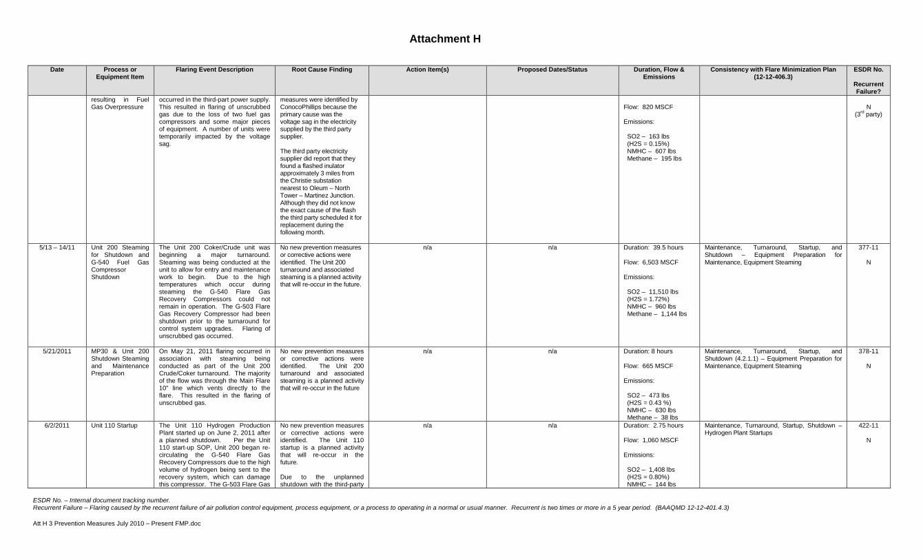
Attachment H
ESDR No. – Internal document tracking number. Recurrent Failure – Flaring caused by the recurrent failure of air pollution control equipment, process equipment, or a process to operating in a normal or usual manner. Recurrent is two times or more in a 5 year period. (BAAQMD 12-12-401.4.3) Att H 3 Prevention Measures July 2010 – Present FMP.doc
Date Process or Equipment Item
Flaring Event Description Root Cause Finding Action Item(s) Proposed Dates/Status Duration, Flow & Emissions
Consistency with Flare Minimization Plan (12-12-406.3)
ESDR No.
Recurrent Failure?
resulting in Fuel Gas Overpressure
occurred in the third-part power supply. This resulted in flaring of unscrubbed gas due to the loss of two fuel gas compressors and some major pieces of equipment. A number of units were temporarily impacted by the voltage sag.
measures were identified by ConocoPhillips because the primary cause was the voltage sag in the electricity supplied by the third party supplier. The third party electricity supplier did report that they found a flashed inulator approximately 3 miles from the Christie substation nearest to Oleum – North Tower – Martinez Junction. Although they did not know the exact cause of the flash the third party scheduled it for replacement during the following month.
Flow: 820 MSCF Emissions: SO2 – 163 lbs (H2S = 0.15%) NMHC – 607 lbs Methane – 195 lbs
N
(3rd party)
5/13 – 14/11 Unit 200 Steaming for Shutdown and G-540 Fuel Gas Compressor Shutdown
The Unit 200 Coker/Crude unit was beginning a major turnaround. Steaming was being conducted at the unit to allow for entry and maintenance work to begin. Due to the high temperatures which occur during steaming the G-540 Flare Gas Recovery Compressors could not remain in operation. The G-503 Flare Gas Recovery Compressor had been shutdown prior to the turnaround for control system upgrades. Flaring of unscrubbed gas occurred.
No new prevention measures or corrective actions were identified. The Unit 200 turnaround and associated steaming is a planned activity that will re-occur in the future.
n/a n/a Duration: 39.5 hours Flow: 6,503 MSCF Emissions: SO2 – 11,510 lbs (H2S = 1.72%) NMHC – 960 lbs Methane – 1,144 lbs
Maintenance, Turnaround, Startup, and Shutdown – Equipment Preparation for Maintenance, Equipment Steaming
377-11
N
5/21/2011 MP30 & Unit 200 Shutdown Steaming and Maintenance Preparation
On May 21, 2011 flaring occurred in association with steaming being conducted as part of the Unit 200 Crude/Coker turnaround. The majority of the flow was through the Main Flare 10” line which vents directly to the flare. This resulted in the flaring of unscrubbed gas.
No new prevention measures or corrective actions were identified. The Unit 200 turnaround and associated steaming is a planned activity that will re-occur in the future
n/a n/a Duration: 8 hours Flow: 665 MSCF Emissions: SO2 – 473 lbs (H2S = 0.43 %) NMHC – 630 lbs Methane – 38 lbs
Maintenance, Turnaround, Startup, and Shutdown (4.2.1.1) – Equipment Preparation for Maintenance, Equipment Steaming
378-11
N
6/2/2011 Unit 110 Startup The Unit 110 Hydrogen Production Plant started up on June 2, 2011 after a planned shutdown. Per the Unit 110 start-up SOP, Unit 200 began re-circulating the G-540 Flare Gas Recovery Compressors due to the high volume of hydrogen being sent to the recovery system, which can damage this compressor. The G-503 Flare Gas
No new prevention measures or corrective actions were identified. The Unit 110 startup is a planned activity that will re-occur in the future. Due to the unplanned shutdown with the third-party
n/a n/a Duration: 2.75 hours Flow: 1,060 MSCF Emissions: SO2 – 1,408 lbs (H2S = 0.80%) NMHC – 144 lbs
Maintenance, Turnaround, Startup, Shutdown – Hydrogen Plant Startups
422-11
N

Attachment H
ESDR No. – Internal document tracking number. Recurrent Failure – Flaring caused by the recurrent failure of air pollution control equipment, process equipment, or a process to operating in a normal or usual manner. Recurrent is two times or more in a 5 year period. (BAAQMD 12-12-401.4.3) Att H 3 Prevention Measures July 2010 – Present FMP.doc
Date Process or Equipment Item
Flaring Event Description Root Cause Finding Action Item(s) Proposed Dates/Status Duration, Flow & Emissions
Consistency with Flare Minimization Plan (12-12-406.3)
ESDR No.
Recurrent Failure?
Compressor had been shutdown prior to this activity and would not have minimized flaring emissions had it been in operation. Flaring of unscrubbed gas occurred during this event.
H2 Plants as detailed in the 10/22/10 event the Plant 4 H2 plant was kept in operation for reliability purposes. This resulted in additional Unit 110 Startups and Shutdowns when the plant is long on Hydrogen production in association with other unit shutdowns.
Methane – 105 lbs
6/5/2011 Unit 110 Unplanned Shutdown due to SPP Upset
On June 5, 2011 an unplanned shutdown of the Unit 110 Hydrogen Plant occurred. This occurred due to low refinery air pressure which shutdown the Unit 110 Pressure Swing Adsorber. Flaring of unscrubbed gas occurred immediately following the shutdown and then during the startup which was initiated approximately three hours following the shutdown.
Unit operator inadvertently closed the B boiler feed water valves.
Consider conducting an alarm rationalization review and DCS/Display changes to highlight SOLs and allow operators to more readily distinguish between turnins on the DCS displays.
COMPLETED 12/15/2011 Duration: 5 hours Flow: 1,681 SCFD Emissions: SO2 – 1,033 lbs (H2S = 0.37%) NMHC – 274 lbs Methane – 221 lbs
Maintenance, Turnaround, Startup, Shutdown (4.2.1.1) – Hydrogen Plant Startup/Shutdowns
428-11
N
6/8 – 9/2011 Unit 246 Depressuring to MP30 Flare due to Planned Shutdown & Steaming of E-301 and Unit 240 Plant 2
On June 8, 2011 Unit 246 was shutting down for maintenance work. As part of the unit shutdown and in order to prepare for maintenance and entry the unit is depressured and purged. The unscrubbed material is vented directly to the MP-30 Flare. In addition to the Unit 246 shutdown work the Unicracker E-301 exchanger was being steamed to restore its heat transfer rate. When this exchanger is steamed the discharge is vented to blowdown and then to the flare.
No new prevention measures or corrective actions were identified. These two activities were planned maintenance activities that will re-occur in the future.
n/a n/a Main and MP30 Flare Totals Duration: 26.50 hours Flow: 1,288 SCFD Emissions: SO2 – 3,833 lbs (H2S = 1.86%) NMHC – 166 lbs Methane – 119 lbs
Maintenance, Turnaround, Startup, and Shutdown – Equipment Preparation for Maintenance, Equipment Steaming Maintenance, Turnaround, Startup, and Shutdown – Equipment Preparation for Maintenance, Depressuring and Purging
424-11
N
6/20 – 21/2011 Unit 246 and Unicracker Startup Associated Flaring and G-540 Startup Issue
On June 20, 2011 Unit 246 was starting up after being shutdown for maintenance work. During the startup materials from the unit are sent to blowdown until they are on-grade. There were numerous other units startups taking place on this day including the Unit 200 Coker/Crude Complex and MP-30 Complex. During these unit startups and while the Unit 246 materials were sent to blowdown flaring of unscrubbed gas occurred
G-540 common discharge pressure setpoint change.
Return setpoint from 70 to 80 psig. COMPLETED Duration: 23.25 hours Flow: 830 MSCF Emissions: SO2 – 4,981 lbs (H2S = 3.6%) NMHC – 406 lbs Methane – 146 lbs
Maintenance, Turnaround, Startup, and Shutdown – High Base Load Upset/Malfunction – Loss of a Compressor
429-11
N
7/8/2011 Unit 110 Planned Startup
Unit 110 was shutdown on June 19, 2011 without any significant flaring. The Unit was shutdown since one of the primary unit’s which utilizes its high purity Hydrogen was shutdown for
The primary cause for flaring was due to the startup of Unit 110.
No new prevention measures or corrective actions were identified. The Unit 110 startup is a planned activity that will re-occur in the future. Turnaround pre-planning is
n/a Duration: 3:10 hours Flow: 1,282 MSCF Emissions
Maintenance, Turnaround, Startup, and Shutdown – Hydrogen Plant Startups
423-11
N

Attachment H
ESDR No. – Internal document tracking number. Recurrent Failure – Flaring caused by the recurrent failure of air pollution control equipment, process equipment, or a process to operating in a normal or usual manner. Recurrent is two times or more in a 5 year period. (BAAQMD 12-12-401.4.3) Att H 3 Prevention Measures July 2010 – Present FMP.doc
Date Process or Equipment Item
Flaring Event Description Root Cause Finding Action Item(s) Proposed Dates/Status Duration, Flow & Emissions
Consistency with Flare Minimization Plan (12-12-406.3)
ESDR No.
Recurrent Failure?
maintenance. The Unit 110 Hydrogen Production Plant started up on July 8, 2011 after the planned shutdown. Flaring of unscrubbed gasses occurred during the startup.
conducted to minimize emissions associated with the startup.
SO2 – 2,160 lbs (H2S = 1.01%) NMHC – 770 lbs Methane – 315 lbs
7/23/2011 3rd Party Electricity Supplier Voltage Sag
On July 23, 2011 a voltage sag occurred in the refinery's third-party power supply. The G-503 Flare Gas Recovery Compressor and other major pieces of equipment were impacted by the voltage sag which resulted in flaring. Several process units were also impacted by the voltage sag. The flaring of unscrubbed gasses occurred.
A voltage sag occurred in the electricity delivered by the refinery's third-party supplier. The third-party supplier reported that a transformer relay opened unexpectedly on the Oleum/Martinez line.
No specific prevention measures were identified by ConocoPhillips because the primary cause was the voltage sag in the electricity provided by the refinery's third-party supplier. The third-party electricity supplier was able to re-close the relay that unexpectedly opened, which restored voltage to the line.
n/a Duration: 4:04 hours Flow: 422 MSCF Emissions SO2 – 3,671 lbs (H2S = 5.24%) NMHC – 249 lbs Methane – 32 lbs
Upset/Malfunction – Loss of a Utility 462-11
N (3rd party)
9/12/11 G-501 Wet Gas Compressor Failure
The Unit 200 Crude/Coker unit was being started up on Sunday, September 11, 2012. As part of the unit startup the G-501 Wet Gas Compressor, which is the compressor for the Coker’s main fractionator, was in the process of starting up. On September 12, 2012, the second day of the unit startup, the G-501 Wet Gas Compressor shutdown. The flaring of unscrubbed gasses occurred.
Top Tower Temperature Too Low
1. Clarify and change start-up procedure to ensure the top tower temperature reaches a clearly defined temperature prior to starting crude charge.
2. Ensure that refresher training for the Coking section start-up procedure includes an emphasis regarding the critical nature of removing water from the tower, and following the procedure regarding when to introduce the wedge valve body steam.
1. COMPLETED February 21, 2012 2. COMPLETED February 21, 2012
Duration: 37:43 hours Flow: 1,547 MSCF Emissions SO2 – 5,543 lbs (H2S = 2.42%) NMHC – 717 lbs Methane – 297 lbs
Upset/Malfunction – Loss of a Major Compressor 547-11
N
Liquid Carryover 1. Review the setting for the High-High Level trip for the G-501 Wet Gas Compressor and assure that there is enough time to protect the compressor from liquid carry-over. Ensure adequate wind down time for the compressor is included in alarm set points.
2. Establish a Safety Operating Limit for the Wet Gas Compressor KO Drum.
1. Evaluation COMPLETED 4/25/13. Determination that existing trips were adequate.
2. COMPLETED 4/25/13
Liquid Removal Issues
1. Ensure the turbine driven reflux pump (G-215A) is considered a critical pump in the G-501 Compressor startup procedure. -
1. COMPLETED
9/25/11 G-501 Wet Gas Compressor Startup
The Unit 200 Crude/Coker unit was being started up on Sunday,
Planned startup of the G-501 Wet Gas Compressor
No new prevention measures or corrective actions were identified.
n/a Duration: 1:12 hours
Maintenance, Turnaround, Startup, & Shutdown – Compressor System Repairs
548-11

Attachment H
ESDR No. – Internal document tracking number. Recurrent Failure – Flaring caused by the recurrent failure of air pollution control equipment, process equipment, or a process to operating in a normal or usual manner. Recurrent is two times or more in a 5 year period. (BAAQMD 12-12-401.4.3) Att H 3 Prevention Measures July 2010 – Present FMP.doc
Date Process or Equipment Item
Flaring Event Description Root Cause Finding Action Item(s) Proposed Dates/Status Duration, Flow & Emissions
Consistency with Flare Minimization Plan (12-12-406.3)
ESDR No.
Recurrent Failure?
September 11, 2012. On September 12, 2012, the second day of the unit startup, the G-501 Wet Gas Compressor failed. (See ConocoPhillips flaring root cause analysis for September 12, 2011 which provides details regarding the Wet Gas Compressor failure.) After repairs had been made to the G-501 compressor it was put back into Wet Gas Service on September 25, 2011. During the startup of the compressor and transition of the G-503 compressor out of Wet Gas Compressor service there was a period of flaring of unscrubbed gas for a little over one hour.
The switch from G-503 from Wet Gas service to Fuel Gas Recovery service was a planned activity to restore the G-501 and G-503 to normal operation. The G-503 Fuel Gas Compressor is designed to be put into Wet Gas Compressor service to optimize the amount of gases routed back to fuel gas during periods of time when the G-501 Wet Gas Compressor is out of service. During the switching process refinery personnel followed a detailed Operating Procedure to perform this activity. This ensures the necessary steps to perform the compressor switch and startup are performed in a safe and efficient manner. This minimizes the period of time in which flaring occurs.
Flow: 120 MSCF Emissions SO2 – 770 lbs (H2S = 3.9%) NMHC – 70 lbs Methane – 40 lbs
N
9/29/11 Unit 110 Planned Startup
Unit 110 was shutdown on September 8, 2011. The Unit 110 Hydrogen Production Plant was re-started up on September 29, 2011 after the shutdown. During the startup of Unit 110 there was flaring of unscrubbed gasses.
The primary cause for flaring was due to the startup of Unit 110.
No new prevention measures or corrective actions were identified. The Unit 110 startup is a planned activity that will re-occur in the future. Turnaround pre-planning is conducted to determine means for reducing flaring.
n/a Duration: 3:07 hours Flow: 1,299 MSCF Emissions SO2 – 1,640 lbs (H2S = 0.76%) NMHC – 326 lbs Methane – 240 lbs
Maintenance, Turnaround, Startup, and Shutdown – Hydrogen Plant Startups
546-11
N
11/29/11 G-503 Flare Gas Compressor Maintenance
The G-503 Flare Gas Recovery Compressor was scheduled for Planned Maintenance in December and was shutdown in preparation for the maintenance. To provide flare gas recovery while G-503 was out of service, the G-540 Flare Gas Recovery Compressors were put in service. However, the volume of gas in the blowdown system was at a level where all the gases could not be recovered with the G-540 compressors at all times throughout the day. This resulted in the flaring of unscrubbed gases that were not treated for sulfur removal.
The volume of gas in the blowdown system was more than the G-540 Flare Gas Compressor capacity.
The G-540 Fuel Gas Recovery Compressors were installed in 2009 to allow for unplanned and planned maintenance to take place on the G-503 Compressor while reducing flaring. Prior to the installation of the G-540 Compressors all gas would have been sent to the flare during periods of maintenance.
n/a Duration: 10:13 hours Flow: 764 MSCF Emissions SO2 – 1,347 lbs (H2S = 1.16%) NMHC – 254 lbs Methane – 163 lbs
Maintenance, Turnaround, Startup, and Shutdown – Compressor Maintenance
063-12
N
12/5/11 Unplanned 3rd Party Hydrogen Plant Shutdown
On December 5, 2011 the Refinery’s third-party Hydrogen Plant that provides a significant portion of hydrogen to the refinery experienced an unplanned shutdown. This resulted
No specific prevention measures were identified by ConocoPhillips to prevent the loss of Hydrogen because the primary root cause was due to the unplanned shutdown of the third-party
Duration: 5:35 hours Flow: 230 MSCF Emissions
Fuel and Hydrogen Gas Balance – Including unplanned Hydrogen supplier shutdowns
108-12
N (3rd Party)

Attachment H
ESDR No. – Internal document tracking number. Recurrent Failure – Flaring caused by the recurrent failure of air pollution control equipment, process equipment, or a process to operating in a normal or usual manner. Recurrent is two times or more in a 5 year period. (BAAQMD 12-12-401.4.3) Att H 3 Prevention Measures July 2010 – Present FMP.doc
Date Process or Equipment Item
Flaring Event Description Root Cause Finding Action Item(s) Proposed Dates/Status Duration, Flow & Emissions
Consistency with Flare Minimization Plan (12-12-406.3)
ESDR No.
Recurrent Failure?
in flaring of unscrubbed gases intermittently on December 5, 2011 from units that shutdown due to the loss of hydrogen or experienced unit upsets. .
3rd Party Root Action Item : Broken weld on ID Fan Jack Shaft
Hydrogen Plant. Repair ID Fan Jack Shaft
COMPLETED 12/5/11
SO2 – 1,025 lbs (H2S = 2.71%) NMHC – 140 lbs Methane – 30 lbs
1/16/12 Unit 110 Startup Following Unplanned Shutdown
Unit 110 experienced an unplanned shutdown on January 15, 2012. During the process of Unit 110 startup there is flaring of unscrubbed gases.
The cause of the shutdown was due to the failure of the Process Logic Controller (PLC) at Unit 110. The PLC failed due to a hardware failure of the Central Processing Unit (CPU) which is the PLC processor.
Replace CPU COMPLETED 1/16/12
Duration: 4:45 hours Flow: 1,628 MSCF Emissions SO2 – 2,870 lbs (H2S = 1.06%) NMHC – 840 lbs Methane – 370 lbs
Unset/Malfunction – Control System Failure Maintenance, Turnaround, Startup, and Shutdown – Hydrogen Plant Startups
157-12
N
1/18 – 1/20 Fuel Gas Balance – 3rd Party H2 Plant not taking RFG A Gas
On January 18, 2012 the third-party Hydrogen Plant took their feed gas coalescer out of service for a filter replacement. Due to the observation of higher than anticipated liquids in the feed gas the Air Liquide Plant blocked out the RFG A feed gas as a precautionary measure. The RFG A is a feed gas generated by the refinery and sent to Air Liquide. This resulted in a fuel gas imbalance at the refinery and the flaring of scrubbed gases.
Liquids in RFG A 1. Evaluate the effectiveness of the piping installed at the RFG A/RFG B boundary and determine if the installation should be modified and upgraded.
2. Third party Hydrogen Plant to evaluate the need to increase water removal capabilities. A tie in to be provided for potential future additional water filter.
1. COMPLETED 3/31/2012 2. COMPLETED tie-in 3rd Qtr 2012
Duration: 55:20 hours Flow: 11,939 MSCF Emissions SO2 – 198 lbs (H2S = 0.01%) NMHC – 11,501 lbs Methane – 2,808 lbs
• Reduced Consumption of Fuel Gas (4.2.1.3)
• Upset/Malfunction (4.2.1.4) – fuel gas quality upsets
158-12
Y
E-424 temperature outlet too low.
Provide a temperature controller on the E-424 compressor discharge cooler. This project will allow the discharge temperature to be controlled so that during cool ambient conditions and reduced flowrates, the RFG A gas temperature can be maximized to prevent condensation of water.
COMPLETED 10/18/12
2/16/12 U110 and U250 Planned Shutdown
On February 16, 2012, steps were taken to shut down Unit 110 Hydrogen Production Plant for a scheduled shutdown to conduct major maintenance. Unit 250 was also conducting a turnaround during this period. Nitrogen purging of a Unit 250 compressor took place during this period. These activities resulted in the flaring of unscrubbed gases.
The primary cause for flaring was the scheduled shutdown of Unit 110 Hydrogen Plant and Unit 250 for a major turnaround to conduct planned maintenance. Equipment and process vessels had to be cleared in order to provide a safe environment for personnel entry.
No new prevention measures or corrective actions were identified. The turnaround activities are planned activities that will re-occur in the future. Turnaround pre-planning was conducted in order to identify means for reducing flaring that may occur.
n/a Duration: 5:07 hours Flow: 1,642 MSCF Emissions SO2 – 2,800 lbs (H2S = 1.37%) NMHC – 670 lbs Methane – 260 lbs
• Maintenance, Turnaround, Startup, Shutdown – Hydrogen Plant Startups and Shutdowns
• Equipment Preparation for Maintenance
159-12
N
3/1 – 3/5/12 Fuel Gas Imbalance Maintenance turnarounds were taking place at units that included large combustion sources during March, 2012. Due to the turnaround, there were periods where all of the fuel gas
The primary cause of the flaring was the shutdown of refinery fuel gas consumers for planned maintenance. This resulted in a fuel gas
Turnaround pre-planning was conducted that identified the potential for fuel gas imbalance. No specific prevention measures were implemented but measures were
n/a Duration: 99 hours Flow: 8,752 MSCF Emissions
Reduced Consumption of Fuel Gas – Fuel Gas Imbalance
242-12
N
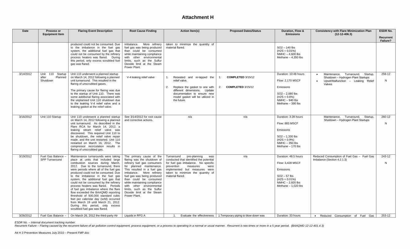
Attachment H
ESDR No. – Internal document tracking number. Recurrent Failure – Flaring caused by the recurrent failure of air pollution control equipment, process equipment, or a process to operating in a normal or usual manner. Recurrent is two times or more in a 5 year period. (BAAQMD 12-12-401.4.3) Att H 3 Prevention Measures July 2010 – Present FMP.doc
Date Process or Equipment Item
Flaring Event Description Root Cause Finding Action Item(s) Proposed Dates/Status Duration, Flow & Emissions
Consistency with Flare Minimization Plan (12-12-406.3)
ESDR No.
Recurrent Failure?
produced could not be consumed. Due to the imbalance in the fuel gas system, the additional fuel gas that could not be consumed by the refinery process heaters was flared. During this period, only excess scrubbed fuel gas was flared.
imbalance. More refinery fuel gas was being produced than could be consumed while maintaining compliance with other environmental limits, such as the Sulfur Dioxide limit at the Steam Power Plant.
taken to minimize the quantity of material flared.
SO2 – 140 lbs (H2S = 0.01%) NMHC – 4,600 lbs Methane – 4,350 lbs
3/14/2012 Unit 110 Startup after Planned Shutdown
Unit 110 underwent a planned startup on March 14, 2012 following a planned unit turnaround. This resulted in the flaring of unscrubbed gases. The primary cause for flaring was due to the startup of Unit 110. There was some additional flaring associated with the unplanned Unit 110 shutdown due to the leaking V-4 relief valve and a leaking gasket at the relief valve.
V-4 leaking relief valve
1. Reseated and re-lapped the
relief valve.
2. Replace the gasket to one with different dimensions. Update documentation to ensure new model gasket will be utilized in the future.
1. COMPLETED 3/15/12 2. COMPLETED 3/15/12
Duration: 10:48 hours Flow: 2,170 MSCF Emissions SO2 – 2,080 lbs (H2S = 0.6%) NMHC – 940 lbs Methane – 390 lbs
• Maintenance, Turnaround, Startup, Shutdown – Hydrogen Plant Startups
• Upset/Malfunction – Leaking Relief Valves
259-12
N
3/16/2012 Unit 110 Startup Unit 110 underwent a planned startup on March 14, 2012 following a planned unit turnaround. As described in the Flare RCA for March 14, 2012, a leaking steam relief valve was discovered. This required Unit 110 to be shutdown, the relief valve repair made, and the unit restarted. Unit 110 restarted on March 16, 2012. The compressor recirculation results in flaring of unscrubbed gas.
See 3/14/2012 for root cause and corrective actions.
n/a n/a Duration: 3:28 hours Flow: 883 MSCF Emissions SO2 – 1,330 lbs (H2S = 0.9%) NMHC – 350 lbs Methane – 170 lbs
Maintenance, Turnaround, Startup, Shutdown – Hydrogen Plant Startups
260-12
N
3/19/2012 Fuel Gas Balance – SPP Turnaround
Maintenance turnarounds were taking place at units that included large combustion sources during March, 2012. Due to the turnaround, there were periods where all of the fuel gas produced could not be consumed. Due to the imbalance in the fuel gas system, the additional fuel gas that could not be consumed by the refinery process heaters was flared. Periods of fuel gas imbalance where the flare flow exceeded the BAAQMD reporting threshold of 500,000 standard cubic feet per calendar day (scfd) occurred from March 19 until March 21, 2012. During this period, only excess scrubbed fuel gas was flared.
The primary cause of the flaring was the shutdown of refinery fuel gas consumers for planned maintenance. This resulted in a fuel gas imbalance. More refinery fuel gas was being produced than could be consumed while maintaining compliance with other environmental limits, such as the Sulfur Dioxide limit at the Steam Power Plant.
Turnaround pre-planning was conducted that identified the potential for fuel gas imbalance. No specific prevention measures were implemented but measures were taken to minimize the quantity of material flared.
n/a Duration: 48.5 hours Flow: 3,428 MSCF Emissions SO2 – 57 lbs (H2S = 0.01%) NMHC – 2,920 lbs Methane – 1,020 lbs
Reduced Consumption of Fuel Gas – Fuel Gas Imbalance (Section 4.2.1.3)
243-12
N
3/26/2012 Fuel Gas Balance – On March 26, 2012 the third-party Air Liquids in RFG A 1. Evaluate the effectiveness 1.Temporary piping to blow down was Duration: 33 hours • Reduced Consumption of Fuel Gas 253-12

Attachment H
ESDR No. – Internal document tracking number. Recurrent Failure – Flaring caused by the recurrent failure of air pollution control equipment, process equipment, or a process to operating in a normal or usual manner. Recurrent is two times or more in a 5 year period. (BAAQMD 12-12-401.4.3) Att H 3 Prevention Measures July 2010 – Present FMP.doc
Date Process or Equipment Item
Flaring Event Description Root Cause Finding Action Item(s) Proposed Dates/Status Duration, Flow & Emissions
Consistency with Flare Minimization Plan (12-12-406.3)
ESDR No.
Recurrent Failure?
AL stopped taking A Gas
Liquide Hydrogen Plant took their feed gas coalescer out of service for a filter replacement. The filter required replacement due to an increase in back pressure on the filter. In order to prevent potential liquids in the feed gas, the Air Liquide Plant blocked out the RFG A feed gas as a precautionary measure. The RFG A is a feed gas generated by the refinery and sent to Air Liquide. This resulted in a fuel gas imbalance at the refinery and the flaring of scrubbed gases.
of the piping installed at the RFG A/RFG B boundary and determine if the installation should be modified and upgraded.
2. Third party Hydrogen Plant
to evaluate the need to increase water removal capabilities. A tie in to be provided for potential future additional water filter.
added for the bleed at the low point in the RFG A gas line prior to going to Air Liquide COMPLETED 3/31/12 2.COMPLETED tie-in 3RD Qtr 2012..
Flow: 4,028 MSCF Emissions SO2 – 67 lbs (H2S = 0.01%) NMHC – 3,260 lbs Methane – 1,045 lbs
(4.2.1.3) • Upset/Malfunction (4.2.1.4) – fuel gas
quality upsets
Y
E-424 temperature outlet too low
Provide a temperature controller on the E-424 compressor discharge cooler. This project will allow the discharge temperature to be controlled so that during cool ambient conditions and reduced flowrates, the RFG A gas temperature can be maximized to prevent condensation of water.
COMPLETED 10/2012
4/25/2012 RFG A out of Air Liquide and Fuel Gas Balance
On April 24, 2012 the RFG A feed gas to the third-party Air Liquide Hydrogen Plant was blocked out as a precautionary measure in preparation for planned turnaround activity. This resulted in a fuel gas imbalance at the refinery and the flaring of scrubbed gases. As the pressure built up in the fuel gas system on April 25, the amount of gas and increase in pressure caused water in the D-7 Hot Coker Blowdown drum to overflow. The water contained H2S and caused local H2S alarms to trigger. In order to maintain the liquid level in the D-7 drum and prevent the H2S alarms, the G-503 flare gas recovery compressor was put into circulation to relieve the pressure on the fuel gas system and the D-7 Drum. This resulted in the flaring of unscrubbed gases.
Sour seal water from D-7 was automatically flushed to an open process sewer that caused H2S alarm.
1. Relocate the D-7 level transmitter to increase pressure activation from 2.2 psig to 4.5 psig. This will prevent pressure fluctuations from tripping the quench water valve.
2. Reduce H2S in seal water by increasing minimum seal water flow and/or setting up routine quench water flushes.
1. COMPLETED 6/1/12
2. COMPLETED 9/26/12
Duration: 19 hours Flow: 2,795 MSCF Emissions SO2 – 5,600 lbs (H2S = 1.2%) NMHC – 1,470 lbs Methane – 550 lbs
• Maintenance, Turnaround, Startup, and Shutdown (4.2.1.1)
• Reduced Consumption of Fuel Gas (4.2.1.3)
• Upset/Malfunction (4.2.1.4) – fuel gas quality upsets
• Emergency (4.2.1.5) – Local H2S alarms near D-7 drum
297-12
N
Sour water from D-7 automatically flushes to an open process sewer that can cause an H2S alarm - Initiation of a project to re-route the Unit 233 pressure control valve flare system
1a. Implement a project to re-route the Unit 233 pressure control valve flare system tie-in location. Install a tie-in location directly to the flare line downstream of 19F-3. (Connected with additional Flare RCA’s).
1a. Target 12/15/15 which is linked with major equipment outage.

Attachment H
ESDR No. – Internal document tracking number. Recurrent Failure – Flaring caused by the recurrent failure of air pollution control equipment, process equipment, or a process to operating in a normal or usual manner. Recurrent is two times or more in a 5 year period. (BAAQMD 12-12-401.4.3) Att H 3 Prevention Measures July 2010 – Present FMP.doc
Date Process or Equipment Item
Flaring Event Description Root Cause Finding Action Item(s) Proposed Dates/Status Duration, Flow & Emissions
Consistency with Flare Minimization Plan (12-12-406.3)
ESDR No.
Recurrent Failure?
tie-in location. 1b. As an alternate solution, Phillips
66 has pending Contra Costa County Land Use and BAAQMD permit applications for the construction of the Propane Recovery Project (PRP). The PRP will reduce the amount of refinery fuel gas combusted on site. This will result in more 3rd party natural gas consumption which can be readily adjusted in response to any rapid changes in demand. Had this incident occurred post-PRP, flaring would not have occurred or would have been greatly minimized. Once the PRP is approved, the project discussed in 1a. above will not be necessary.
1b. Target 1/15/16
4/26 – 5/1/12 Fuel Gas Imbalance During UK T/A
In late April, 2012, a planned shutdown was conducted at the Unicracker Complex to perform scheduled maintenance on several units. Flaring occurred on May 19, 2012 while the G-540 Flare Gas Recovery Compressors were shutdown. The Flare Gas Compressors were shutdown during the Unit 244 Reformer Catalyst Activation startup procedure which led to flaring of unscrubbed gas.
The primary cause of flaring was the shutdown of the G-540 Flare Gas Recovery Compressors during hydrogen and nitrogen purge steps.
Preplanning was conducted to identify periods of expected flaring to identify means for minimizing flaring. Communication between the Unit 200 Operator that operates the Flare Gas Recovery Compressors and Unit 244 takes place in advance of this work occurring. This ensures that the activity is planned and the period in which the flare gas recovery compressor is shutdown is minimized.
n/a Duration: 114 hours Flow: 18,000 MSCF Emissions SO2 – 623 lbs (H2S = 0.01%) NMHC – 10,050 lbs Methane – 3,700 lbs
Reduced consumption of fuel gas – fuel gas imbalance (4.2.1.3)
306-12
N
5/19/12 Unit 244 Catalyst Reactivation and Nitrogen Purging
A planned shutdown was conducted at the Unicracker Complex to perform scheduled maintenance on several units. Flaring occurred on May 19, 2012 while the G-540 Flare Gas Recovery Compressors were shutdown. The Flare Gas Compressors were shutdown during the Unit 244 Reformer Catalyst Activation startup procedure which led to flaring of unscrubbed gas.
Preplanning was conducted to identify periods of expected flaring to identify means for minimizing flaring. Communication between the Unit 200 Operator that operates the Flare Gas Recovery Compressors and Unit 244 takes place in advance of this work occurring. This ensures that the activity is planned and the period in which the flare gas recovery compressor is shutdown is minimized.
n/a n/a Duration: 12.83 hours Flow: 4,300 MSCF Emissions SO2 – 2,260 lbs (H2S = 0.32%) NMHC – 2,130 lbs Methane – 800 lbs
• Maintenance, Turnaround, Startup, Shutdown – Unit startup (Section 4.2.1.1)
303-12
N
5/23-5/29/12 Unit 240 Plant 3 Unscheduled SD and Unit 246 D-803 Overhead to Flare
The Unit 246 Hydrocracker D-803 stripper overhead was routed to the flare gas recovery system as a result of the unscheduled shutdown of Unit 240 Plant 3. The addition of the D-803 stripper overhead gases to the flare
E-316 Fin Fan Leak repair E-316 Fin Fan Leak repair - Re-rolling of 320 tubes in areas where the E-316 leaks occurred followed by the re-start of UK Plant 3. Plant 3
COMPLETED 5/27/12 Duration: 111.5 hours Flow: 8,970 MSCF Emissions
• Upset/Malfunction - Loss of Air Fin (4.2.1.4)
• Reduced Consumption of Fuel Gas (4.2.1.3)
• Upset/Malfunction (4.2.1.4) – fuel gas
320-12
N

Attachment H
ESDR No. – Internal document tracking number. Recurrent Failure – Flaring caused by the recurrent failure of air pollution control equipment, process equipment, or a process to operating in a normal or usual manner. Recurrent is two times or more in a 5 year period. (BAAQMD 12-12-401.4.3) Att H 3 Prevention Measures July 2010 – Present FMP.doc
Date Process or Equipment Item
Flaring Event Description Root Cause Finding Action Item(s) Proposed Dates/Status Duration, Flow & Emissions
Consistency with Flare Minimization Plan (12-12-406.3)
ESDR No.
Recurrent Failure?
gas recovery system led to periods where the refinery’s flare gas recovery compressors could not compress all of the gas in the system due to gas quantity. During these periods unscrubbed gas was flared due to the addition of the D-803 overhead. The D-803 stripper overhead normally goes to Plant 3 in the Unit 240 UK. When the UK Plant 3 is shutdown, however, the D-803 stripper overhead is routed to the flare gas recovery system. On May 23, 2012, UK Plant 3 needed to be shut down to repair a leak that was found in the E-316 fin fan cooler. The E-316 fin fan cools the UK Plant 3 D-305 Fractionator bottoms stream.
SO2 – 7,815 lbs (H2S = 0.38%) NMHC – 6,790 lbs Methane – 1,665 lbs
quality upsets • Maintenance, Turnaround, Startup, and
Shutdown (4.2.1.1)
E-316 Design
Review the process in Plant 3 to determine if the E-316 fin fan unit can be replaced with shell and tube heat exchanger.
Target 6/7/2015
5/31-6/1/12 Unit 110 Planned Startup following Shutdown
Unit 110 underwent a planned shutdown on May 3, 2012 due to lower hydrogen demand related to planned turnaround activity at the Unicracker complex. Flaring of unscrubbed gases occurred in association with the Unit 110 startup.
None, this was a planned startup with anticipated flaring.
n/a n/a Duration:3.58 hours Flow: 448 MSCF Emissions SO2 – 2,220 lbs (H2S = 2.9%) NMHC – 280 lbs Methane – 80 lbs
• Maintenance, Turnaround, Startup, Shutdown – Hydrogen Plant Startups
311-12
N
7/24/12 UK Relief Valve Leak following T/A
After the start-up of the Unicracker (UK) Complex following a turnaround, Phillips 66 detected a low rate of flare flow at the Main Flare (in the range of 300,000 to 400,000 scf per day of unscrubbed gas). Upon investigation it was determined the UK Plant 2 100 lb. relief valve (2HV023) on the 2F-201 High Pressure (HP) Separator was the source of the flow to the flare. During this period, there were three instances (7/24/12 to 7/27/12, 8/1/12 and 8/4/12 to 8/6/12) where H2S in the flare samples indicated that more than 500 pounds of SO2 had been emitted and/or more than 500,000 scf of vent gas were flared during a calendar day. All three instances were caused by the
UK Plant 2 100 lb Relief Valve (2HV023) Leaking to Flare
Block in existing 2HV023 relief valve and install new one in alternate location.
COMPLETED 8/12/12 Duration:72 hours Flow: 1,308 MSCF Emissions SO2 – 1,580 lbs (H2S = 0.74%) NMHC – 790 lbs Methane – 330 lbs
• High Base/Continuous Load – Leaking Relief Valve (4.2.1.2)
• Upset/Malfunction – Leaking Relief Valves (4.2.1.4)
435-12
N
8/1/12 UK Relief Valve Leak following T/A
“ “ “ Duration:24 hours Flow: 545 MSCF Emissions SO2 – 300 lbs (H2S = 0.33%) NMHC – 340 lbs
“ 437-12
N (on-going)

Attachment H
ESDR No. – Internal document tracking number. Recurrent Failure – Flaring caused by the recurrent failure of air pollution control equipment, process equipment, or a process to operating in a normal or usual manner. Recurrent is two times or more in a 5 year period. (BAAQMD 12-12-401.4.3) Att H 3 Prevention Measures July 2010 – Present FMP.doc
Date Process or Equipment Item
Flaring Event Description Root Cause Finding Action Item(s) Proposed Dates/Status Duration, Flow & Emissions
Consistency with Flare Minimization Plan (12-12-406.3)
ESDR No.
Recurrent Failure?
UK 2HV023 relief valve leaking to the Main Flare which resulted in the flaring of unscrubbed gas.
Methane – 100 lbs 8/4/12 UK Relief Valve
Leak following T/A “ “ “ Duration:72 hours
Flow: 1,212 MSCF Emissions SO2 – 1,677 lbs (H2S = 0.83%) NMHC – 704 lbs Methane – 336 lbs
“ 441-12
N (on-going)
8/24/12 UK Unplanned Shutdown
On August 24, 2012 at approximately 1:00 PM, Unit 240 Plant 2 had an unscheduled shutdown. During the shutdown, the unit de-pressured directly to the main flare, bypassing the flare gas recovery compressors. Gases were also vented to the flare during the subsequent startup. The shutdown and startup resulted in the flaring of unscrubbed gases. The Unit 240 Plant 2 shutdown and subsequent startup caused the pressure to build up in the fuel gas system, which led to periodic flaring of scrubbed gases. The increase in fuel gas flow to the flare can cause water in the D-7 blowdown drum to overflow. The water can contain H2S and cause local H2S sensors to alarm. To maintain the liquid level in the D-7 drum and prevent the H2S alarms, the G-503 flare gas recovery compressor was put into circulation to reduce the pressure on the fuel gas system and the D-7 Drum. This resulted in the flaring of unscrubbed gases.
Lack of policy for process trip systems to be placed in Bypass while maintenance work is being performed on the tripped software. “
“Develop a task safety analysis form specific to Process Control work tasks.
COMPLETED 5/28/12 Duration:61 hours Flow: 18,470 MSCF Emissions SO2 – 98,680 lbs (H2S = 3.81%) NMHC – 13,229 lbs Methane – 1,922 lbs
• Reduced Consumption of Fuel Gas (4.2.1.3) • Upset/Malfunction (4.2.1.4) – control system
failure • Upset/Malfunction (4.2.1.4) – fuel gas
quality upsets • Maintenance, Turnaround, Startup, and
Shutdown (4.2.1.1)
474-12
N
Sour seal water from D-7 automatically flushes to an open process sewer that causes an H2S alarm
1. Relocate the D-7 level transmitter to increase pressure activation from 2.2 psig to 4.5 psig. This will prevent pressure fluctuations from tripping the quench water valve.
2. Reduce H2S in seal water by increasing minimum seal water flow and/or setting up routine quench water flushes.
1. COMPLETED 6/1/12 as part of a previous Flare Event (4/25/12). This corrective action may have reduced the severity of this flare activity. 2. COMPLETED 9/26/12
Sour water from D-7 automatically flushes to an open process sewer that can cause an H2S alarm -
1a. Implement a project to re-route the Unit 233 pressure control valve flare system tie-in location. Install a tie-in location directly to the flare line
1a. Target 12/15/15 which is linked with major equipment outage.

Attachment H
ESDR No. – Internal document tracking number. Recurrent Failure – Flaring caused by the recurrent failure of air pollution control equipment, process equipment, or a process to operating in a normal or usual manner. Recurrent is two times or more in a 5 year period. (BAAQMD 12-12-401.4.3) Att H 3 Prevention Measures July 2010 – Present FMP.doc
Date Process or Equipment Item
Flaring Event Description Root Cause Finding Action Item(s) Proposed Dates/Status Duration, Flow & Emissions
Consistency with Flare Minimization Plan (12-12-406.3)
ESDR No.
Recurrent Failure?
Initiation of a project to re-route the Unit 233 pressure control valve flare system tie-in location.
downstream of 19F-3. (Connected with additional Flare RCA’s).
1b. As an alternate solution, Phillips 66 has pending Contra Costa County Land Use and BAAQMD permit applications for the construction of the Propane Recovery Project (PRP). The PRP will reduce the amount of refinery fuel gas combusted on site. This will result in more 3rd party natural gas consumption which can be readily adjusted in response to any rapid changes in demand. Had this incident occurred post-PRP, flaring would not have occurred or would have been greatly minimized. Once the PRP is approved, the project discussed in 1a. above will not be necessary.
1b. Target 1/15/16
8/27/12 RFG A Backed out of AL due to Higher than Normal Sulfur Content
Portions of the Unicracker Complex were in startup on August 27, 2012 following an unplanned shutdown (see ESDR-474-12). At approximately 11:27 PM, flaring began when the third party Hydrogen Plant blocked out feed gas (RFG A) from Phillips 66 due to unexpectedly higher than normal sulfur content. Flaring of scrubbed fuel gas occurred until the following day at approximately 5:17 PM due to high fuel gas system pressure.
Natural Gas was added to RFG A upstream of D402 rather than downstream.
1. Natural gas should be added downstream of D-402.
2. Add a tag on the D-402
upstream natural gas line to indicate this should not be utilized.
1. COMPLETED approx. 10/17/2012.
2. COMPLETED 11/27/12
Duration: 17.9 hours Flow: 2,266 MSCF Emissions SO2 – 100 lbs (H2S = 0.01 %) NMHC – 8,650 lbs Methane – 458 lbs
• Reduced Consumption of Fuel Gas – Fuel Gas Imbalance (Section 4.2.1.3)
• Upset/Malfunction (4.2.1.4) – fuel gas quality upsets
503-12
N
9/10/12 Unit 110 Hydrogen Vent Fire
On September 10, 2012 at approximately 7:00 AM, the G-503 flare gas recovery compressor was circulated due to a large amount of hydrogen being sent to the flare gas recovery system. In some cases, too much hydrogen can cause the heating value of the fuel gas to be too low, which requires the compressor to be shut down. At the time the compressor was being circulated, there was excess hydrogen being produced at the refinery during the startup of the third party Air Liquide Hydrogen Plant (Air Liquide). The excess hydrogen being produced by the Unit 110 Hydrogen Plant was sent to the flare gas recovery system. Circulation of the G-503 flare gas recovery compressor
The Unit 110 operating procedure (REOP-21) does not adequately address Unit 110 atmospheric vent operating parameters.
1. Revise REOP-21 "Emergency Loss of Hydrogen," to include a note regarding the Unit 110 atmospheric hydrogen vent operating limitations.
2. Review creation of a new normal operating procedure (NOP) for operation of the Unit 110 atmospheric hydrogen vent and how to respond to high flow. COMPLETED 12/20/2012
COMPLETED 1/9/2013 COMPLETED 1/9/2013
Duration:10.25 hours Flow: 5,628 MSCF Emissions SO2 – 11,587 lbs (H2S = 1.24 %) NMHC – 1,760 lbs Methane – 620 lbs
• Emergency, flame at Unit 110 atmospheric hydrogen vent (4.2.1.5)
• Hydrogen Gas Balance – excess hydrogen production following startup or shutdown(4.2.1.1)
499-12
N

Attachment H
ESDR No. – Internal document tracking number. Recurrent Failure – Flaring caused by the recurrent failure of air pollution control equipment, process equipment, or a process to operating in a normal or usual manner. Recurrent is two times or more in a 5 year period. (BAAQMD 12-12-401.4.3) Att H 3 Prevention Measures July 2010 – Present FMP.doc
Date Process or Equipment Item
Flaring Event Description Root Cause Finding Action Item(s) Proposed Dates/Status Duration, Flow & Emissions
Consistency with Flare Minimization Plan (12-12-406.3)
ESDR No.
Recurrent Failure?
resulted in the flaring of unscrubbed gases.
10/3/12 U246 Depressurization to Flare and Planned SD
On October 3, 2012 Unit 246 was being shut down for maintenance work. As part of the unit shutdown, and to prepare for maintenance and entry, the unit was depressured and purged. The purged material was vented directly to the MP-30 Flare and resulted in the flaring of unscrubbed gases.
No new prevention measures or corrective actions were identified. These activities were planned maintenance activities that will re-occur in the future.
n/a n/a Duration:28.5 hours Flow: 5,265 MSCF Emissions SO2 – 87 lbs (H2S = 0.01%) NMHC – 150 lbs Methane – 986 lbs
Maintenance, Turnaround, Startup, and Shutdown – Equipment Preparation for Maintenance, Depressuring and Purging
537-12
N
10/4/12 U240 Plant 2 Unplanned SD due to failure of G-203B H2 Make Up Compressor
On October 04, 2012, Unit 240 Plant 2 had an unscheduled shutdown at approximately 9:05 PM caused, in part, by the failure of the 3rd stage of the G-203B Hydrogen Makeup Compressor. Prior to the shutdown at approximately 5:50 PM, the G-203B Hydrogen Makeup Compressor at Unit 240 developed a mechanical issue that resulted in one of the relief valves lifting and releasing hydrogen to the flare. Gases were also vented to the flare during the subsequent startup after repairs of the G-203B Compressor were complete. The shutdown and startup resulted in the flaring of unscrubbed gases.
1. D-203 Catalyst Bed 4 had temperature gradient prior to the incident
a. Expand the Unit 240 Plant 2 Reactor Operating Guidelines to improve temperature gradient management and actions to take to minimize gradients.
b. Improve reactor temperature alarming. Consider installing alarms on the DCS and OIS Target board.
c. Provide refresher training on
The Plant 2 Reactor Operating Guidelines and training on emergency events.
a. COMPLETED 3/25/13
b. COMPLETED 3/25/13 Upon detailed review it was determined that existing monitoring was consistent with industry best practices and per P66’s internal recommendations. Thus, no additional monitoring was added.
c. COMPLETED 8/29/13
Duration:22.6 hours Flow: 7,111 MSCF Emissions SO2 – 22,100 lbs (H2S = 2.25 %) NMHC – 2,479 lbs Methane – 941 lbs
• Reduced Consumption of Fuel Gas (4.2.1.3)
• Maintenance, Turnaround, Startup, and Shutdown (4.2.1.1)
• Upset/Malfunction – Loss of other compressors (G-203B) (4.2.1.4)
577-12
N
2. G-203B shutdown because of lube oil injection system failure.
Complete the Failure Analysis Summary Report and implement recommended actions.
COMPLETED report 12/17/12, Associated action items 1/31/13.
3. Sour water from D-7 automatically flushes to an open process sewer that can cause an H2S alarm - Initiation of a project to re-route the Unit 233 pressure control valve flare system tie-in location.
1a. Implement a project to re-route the Unit 233 pressure control valve flare system tie-in location. Install a tie-in location directly to the flare line downstream of 19F-3. (Connected with additional Flare RCA’s).
1b. As an alternate solution, Phillips 66 has pending Contra Costa County Land Use and BAAQMD permit applications for the construction of the Propane Recovery Project (PRP). The PRP will reduce the amount of refinery fuel gas combusted on site. This will result in more 3rd party
1a. Target 12/15/15 which is linked with major equipment outage. 1b. Target 1/15/16

Attachment H
ESDR No. – Internal document tracking number. Recurrent Failure – Flaring caused by the recurrent failure of air pollution control equipment, process equipment, or a process to operating in a normal or usual manner. Recurrent is two times or more in a 5 year period. (BAAQMD 12-12-401.4.3) Att H 3 Prevention Measures July 2010 – Present FMP.doc
Date Process or Equipment Item
Flaring Event Description Root Cause Finding Action Item(s) Proposed Dates/Status Duration, Flow & Emissions
Consistency with Flare Minimization Plan (12-12-406.3)
ESDR No.
Recurrent Failure?
natural gas consumption which can be readily adjusted in response to any rapid changes in demand. Had this incident occurred post-PRP, flaring would not have occurred or would have been greatly minimized. Once the PRP is approved, the project discussed in 1a. above will not be necessary.
1/18/13 U246 Unplanned Shutdown due to failure of 8G-826B Forced Draft Fan
On January 8, 2013, the Unit 246 Heavy Gas Oil Hydrocracker had an unscheduled shutdown. During the shutdown, the refinery’s G-503 flare gas recovery compressor was taken offline due to gas quality concerns due to the large amount of hydrogen being sent to the flare gas recovery system. The G-503 flare gas recovery compressor does not operate properly with high amounts of hydrogen and can be permanently damaged. Two of the liquid ring compressors were in operation, but could not compress all of the gas being sent to the flare. This resulted in the flaring of unscrubbed gas.
VFD Cabinet High Temperature
Install exhaust fans in the enclosure to direct hot air out of the enclosure.
COMPLETED 4/10/13 Duration:9 hours Flow: 227 MSCF Emissions SO2 – 970 lbs (H2S = 2.64 %) NMHC – 183 lbs Methane – 46 lbs
• Upset/Malfunction - Loss of Forced Draft Fan, 8G-826B (4.2.1.4)
• Maintenance, Turnaround, Startup, and Shutdown (4.2.1.1)
071-13
N
D-803 Overhead Offgrade to blowdown during Startup
1. Revise startup procedure to notify Unit 200 when D-803 is going to blowdown. Unit 200 may be able to delay drum switches and work to optimize flow to the flare gas system.
2. Revise startup procedure to include increased D-803 Overhead sampling frequency to once per hour. This will allow the on grade determination to be made more quickly and reduce the time the material goes to blowdown.
3. Revise startup procedure to increase maximum D-803 Overhead on-grade specification to 5 ppm total sulfur from 2 ppm to minimize the time the material goes to blowdown.
COMPLETED 2/4/13 COMPLETED 2/4/13 COMPLETED 2/4/13

Attachment H
ESDR No. – Internal document tracking number. Recurrent Failure – Flaring caused by the recurrent failure of air pollution control equipment, process equipment, or a process to operating in a normal or usual manner. Recurrent is two times or more in a 5 year period. (BAAQMD 12-12-401.4.3) Att H 3 Prevention Measures July 2010 – Present FMP.doc
Date Process or Equipment Item
Flaring Event Description Root Cause Finding Action Item(s) Proposed Dates/Status Duration, Flow & Emissions
Consistency with Flare Minimization Plan (12-12-406.3)
ESDR No.
Recurrent Failure?
4/11/13 U246 Unplanned Shutdown due to G801 Charge Pump Failure
On April 10, 2013, the Unit 246 Heavy Gas Oil Hydrocracker had an unscheduled shutdown. As part of the unit shutdown the unit was depressured. The depressured material was vented directly to the MP-30 Flare and resulted in the flaring of unscrubbed gases.
1. Routine equipment rounds did not include explicit instructions regarding G-801 motor oil levels and related parameters
Update the Operator Rounds sheets to include explicit instructions to check the G-801 motor oil level gauges, temperature of oil supply tubing at each branch from the header pipe, levels in constant level oiler, oil return flow rate and bearing housing air-purged seal air pressure each shift.
COMPLETED 5/2/13 Duration:7 hours Flow: 1,167 MSCF Emissions SO2 – 814 lbs (H2S = 0.42 %) NMHC – 127 lbs Methane – 210 lbs
• Upset/Malfunction – Equipment failure which results in an immediate or controlled unit shutdown (e.g. charge pump failure) (4.2.1.4)
• Maintenance, Turnaround, Startup, and Shutdown – Equipment Preparation for Maintenance, Depressuring and Purging
162-13
N
2. No back up oil supply in the event the supply orifice becomes blocked.
Install an additional level gauge and a constant level oiler on the G-801 motor’s bearing housings to allow changes in oil level to be more apparent to Operators, and to provide a back up supply of oil in the event the flood lube supply orifice is blocked.
COMPLETED 4/20/13
6/10/13 Removal of RFG A Feed to Air Liquide due to Presence of Atomized Oil
On June 10, 2013, the Air Liquide Hydrogen Plant located next to the refinery experienced a sudden increase in differential pressure in its coalescer filter. Feed gas referred to as RFG A flows through the coalescer from the Phillips 66 Rodeo Refinery to the Air Liquide Hydrogen Plant and then on to its Hydrogen Reformer. At approximately 11:00 AM RFG A was shutout by Air Liquide. This resulted in flaring of scrubbed gases. During the upset, flow from the Unicracker D-301 Debutanizer triggered an alarm. Flow was diverted from the Unit 233 Fuel Gas System to the flare to respond to the alarm and to minimize additional unit impacts. This resulted in the flaring of unscrubbed gases. Flaring occurred intermittently from June 10 through June 11, 2013 at 9:25 PM.
1. 4-PIC-176 Incorrect Calibration and Erroneous Pressure Indication
1. Re-calibrate 4-PIC-176. 2. Update 4-PIC-176
calibration documentation to reflect necessary pressure offset adjustment for glycol filled leg. .
3. Consider adding a 4-PIC-176 low pressure alarm set at 145 psig.
1. COMPLETED 6/28/13 2. COMPLETED 8/26/13
3. COMPLETED 9/6/13. Low pressure alarm was added as originally premised.
Duration:22 hours Flow: 1,818 MSCF Emissions SO2 – 786 lbs (H2S = 0.27 %) NMHC – 1,516 lbs Methane – 348 lbs
• Reduced Consumption of Fuel Gas (4.2.1.3)
• Upset/Malfunction (4.2.1.4) - Failure of Instrumentation
• Upset/Malfunction (4.2.1.4) – fuel gas quality upsets
227-13
N
3. 5-FIC-015 Conservative High Flow Alarm Set Point -
Adjust 3 FIC 015 High Flow Alarm Set Point from 2.5 MMSCFD to 5 MMSCFD to allow for more sour gas to be vented to U233 fuel gas system rather than to blowdown.
COMPLETED 7/30/13
4. Air Liquide Coalescer Location -
Meet with Air Liquide to discuss possibility of relocating existing coalescer on RFG A to upstream of 120-FIC-115 control valve or to provide a new Knock Out vessel upstream of 120-FIC-115.
COMPLETED 8/15/13. On-going discussions are continuing about feasibility of this project.

Attachment H
ESDR No. – Internal document tracking number. Recurrent Failure – Flaring caused by the recurrent failure of air pollution control equipment, process equipment, or a process to operating in a normal or usual manner. Recurrent is two times or more in a 5 year period. (BAAQMD 12-12-401.4.3) Att H 3 Prevention Measures July 2010 – Present FMP.doc
Date Process or Equipment Item
Flaring Event Description Root Cause Finding Action Item(s) Proposed Dates/Status Duration, Flow & Emissions
Consistency with Flare Minimization Plan (12-12-406.3)
ESDR No.
Recurrent Failure?
7/3-5/2013 Unit 110 Hydrogen Plant Unplanned Shutdown
On July 3, 2013, the Unit 110 Hydrogen Plant (U110) experienced an unscheduled shutdown. The U110 shutdown resulted in the shutdown of the Air Liquide Hydrogen Plant. The loss of hydrogen from U110 and Air Liquide also resulted in multiple refinery process unit upsets and the flaring of scrubbed and unscrubbed gases during the shutdown and subsequent startup of these units.
PV-79D Valve Actuator Failed
1. Have manufacturer conduct failure analysis.
2. Inspect all PSA Valve Actuators.
3. Conduct study to determine if all 10 PSA “D” valves should be replaced
4. Controls upgrade to allow feed rate at unit to automatically change with PSA bed operation changes.
1. COMPLETED 12/18/13 2. COMPLETED 12/18/13 3. Determined to complete Item 4 in
lieu of this item. D valve replacements occurring over time.
4. COMPLETED August 2014
Duration:37.6 hours Flow: 7,767 MSCF Emissions SO2 – 17,035 lbs (H2S = 1.32 %) NMHC – 5,002 lbs Methane – 1,382 lbs
• Upset/Malfunction (4.2.1.4) – failure of PSA valve
• Upset/Malfunction (4.2.1.4) – High volumes of hydrogen in the flare gas recovery system
• Upset/Malfunction (4.2.1.4) – Unplanned/sudden shutdown of 3rd party Hydrogen Plant
• Reduced Consumption of Fuel Gas (4.2.1.3) – fuel consumers are shutdown
• Upset/Malfunction (4.2.1.4) – fuel gas quality upsets
241-13
N
Air Liquide Feed Gas Compressor Seal Vent Pressure Set Point Too Low
Increase the set point from 22.8 psig to 33 psig.
COMPLETED 7/15/13
6/1/2014 Unit 240 Plant 3 Instrument Upset
On June 1, 2014, an upset occurred at the Unicracker Plant 3 that affected the Refinery Fuel Gas “A” (RFG A) that is sent to the nearby third party Air Liquide Hydrogen Plant. Due to pressure and specific gravity fluctuations of the RFG A during the incident, Air Liquide shutout the RFG A gas as feed to their process. This resulted in the flaring of refinery fuel gas at the refinery. In addition, due to potentially high pressure in the fuel gas system, the G-503 Flare Gas Recovery Compressor was shutdown. This resulted in the flaring of scrubbed and unscrubbed gases
No alarms to indicate where the initial upset occurred. 3FIC019 showed flow even though valve was closed due to inaccurate meter reading (3FIC019 showed a reading of 11,500 BPD while valve output was 0%)
1. 3FIC019 immediate repair and restoration of accurate reading.
2. Set a low level output alarm for 3FIC019.OP.
3. Consider lowering high level alarm for 3LIC008 and associated level setpoint control.
1. COMPLETED June 1, 2014 2. COMPLETED 7/23/14 3. COMPLETED 7/23/14
Duration:6.83 hours Flow: 1,504 MSCF Emissions SO2 – 3,800 lbs (H2S = 1.52 %) NMHC – 1,041 lbs Methane – 224 lbs
• Reduced Consumption of Fuel Gas (4.2.1.3)
• Upset/Malfunction (4.2.1.4) – fuel gas quality upsets
• Emergency (4.2.1.5) – Local H2S alarms near D-7 drum
225-14
N
Inaccurate 3FIC019 reading and 3LIC008 level indicator float sticking - Conduct cleaning and calibration for 3FIC019 and other meters. Consider comprehensive review of Plant 3/RFG A system steam tracing.
Consider options for safe, routine cleaning of 3LIC008.
COMPLETED 9/23/14. Additional work to be conducted during 2015 t/a.
Air Liquide removal of RFG A from process feed. -.
Discuss strategies with Air Liquide for when RFG A feed is stopped to minimize impact to the Refinery fuel gas system
COMPLETED 9/9/2014
Sour water from D-7 automatically flushes to an open process sewer that can cause an H2S alarm - Initiation of a project to re-route the Unit 233 pressure control valve flare system tie-
1a. Implement a project to re-route the Unit 233 pressure control valve flare system tie-in location. Install a tie-in location directly to the flare line downstream of 19F-3. (Connected with additional past Flare RCA’s).
Target 12/15/15 which is linked with major equipment outage.

Attachment H
ESDR No. – Internal document tracking number. Recurrent Failure – Flaring caused by the recurrent failure of air pollution control equipment, process equipment, or a process to operating in a normal or usual manner. Recurrent is two times or more in a 5 year period. (BAAQMD 12-12-401.4.3) Att H 3 Prevention Measures July 2010 – Present FMP.doc
Date Process or Equipment Item
Flaring Event Description Root Cause Finding Action Item(s) Proposed Dates/Status Duration, Flow & Emissions
Consistency with Flare Minimization Plan (12-12-406.3)
ESDR No.
Recurrent Failure?
in location.
1b. As an alternate solution, Phillips 66 has pending Contra Costa County Land Use and BAAQMD permit applications for the construction of the Propane Recovery Project (PRP). The PRP will reduce the amount of refinery fuel gas combusted on site. This will result in more 3rd party natural gas consumption which can be readily adjusted in response to any rapid changes in demand. Had this incident occurred post-PRP, flaring would not have occurred or would have been greatly minimized. Once the PRP is approved, the project discussed in 1a. above will not be necessary.
Target 1/15/16.
9/25/2014 Unit 246 B-801 A/B Heater Shutdown
On September 25, 2014, the Unit 246 Heavy Gas Oil Hydrocracker had an upset which led to a brief, unscheduled, shutdown and subsequent startup of the Unit 246 B-801 A/B heater. During the shutdown, and subsequent startup, the refinery’s flare gas recovery system could not compress all of the gas being sent to the flare. This resulted in the flaring of unscrubbed gas.
G-826A speed transmitter, ST-313A, failure
Replace ST-313A COMPLETED 10/2014 Duration: 3.0 hours Flow: 320 MSCF Emissions SO2 – 895 lb (H2S = 1.7%) NMHC - 174 lb CH4 – 47 lb
• Upset/Malfunction - Loss of Forced Draft Fan, G-826A (4.2.1.4)
• Upset/Malfunction – Failure of instrumentation to function as designed (4.2.1.4)
• Maintenance, Turnaround, Startup, and Shutdown (4.2.1.1)
341-14
N
9/30 – 10/1/2014 Removal of RFG A Feed to Air Liquide
On September 30, 2014 the third-party Air Liquide Hydrogen Plant took their feed gas coalescer out of service for a filter replacement. The differential pressure on the coalescer filter had been increasing. The filter replacement is done on a periodic basis to prevent a sudden increase in differential pressure. Feed gas referred to as RFG A flows through the coalescer from the Phillips 66 Rodeo Refinery to the Air Liquide Hydrogen Plant and then on to its Hydrogen Reformer. At approximately 10:50 AM RFG A was shutout by Air Liquide. This resulted in flaring of scrubbed gases due to fuel gas imbalance.
Air Liquide removal of RFG A from process feed.
Phillips 66 communicated with Air Liquide regarding the filter replacements. Phillips 66 and Air Liquide discussed having better communication prior to Air Liquide conducting the filter replacements and notifying appropriate refinery personnel so that flaring can be minimized or eliminated.
COMPLETED 10/2014 Duration: 27.58 hours Flow: 1,510 MSCF Emissions SO2 –142 lb (H2S = 0.06 %) NMHC - 1208 lb CH4 –289 lb
• Reduced Consumption of Fuel Gas (4.2.1.3) – Third Party Hydrogen Plant planned or unplanned maintenance on feed filters
342-14
Y
10/23/2014 Unit 240 Plant 2 Unplanned Shutdown
On October 23, 2014, Unit 240 Plant 2 had an upset which led to an unscheduled shutdown. At approximately 9:45 am, several alarms (common trouble, accelerometer and high vibration) occurred at the G-203A
Failure of G-203A Hydrogen Makeup compressor second stage piston rod due to inadequate design.
Mitigate failure risk by eliminating flaw in heater hole by reducing stress riser; radius the bottom of the heater hole. Evaluate replacing the piston rods with the newer design.
Target 1/30/16 Duration: 7.1 hours Flow: 2,264 MSCF Emissions
• Upset/Malfunction - Loss of Other Compressors, G-203A (4.2.1.4)
• Maintenance, Turnaround, Startup, and Shutdown
369-14
N

Attachment H
ESDR No. – Internal document tracking number. Recurrent Failure – Flaring caused by the recurrent failure of air pollution control equipment, process equipment, or a process to operating in a normal or usual manner. Recurrent is two times or more in a 5 year period. (BAAQMD 12-12-401.4.3) Att H 3 Prevention Measures July 2010 – Present FMP.doc
Date Process or Equipment Item
Flaring Event Description Root Cause Finding Action Item(s) Proposed Dates/Status Duration, Flow & Emissions
Consistency with Flare Minimization Plan (12-12-406.3)
ESDR No.
Recurrent Failure?
Hydrogen Makeup compressor. At 9:47 am, the G-203A machine was shut down and feed was pulled from the Unit. As part of the designed shutdown procedure, Unit 240 Plant 2 was depressured directly to the flare, bypassing the refinery’s flare gas recovery system. During the depressuring process, the large amount of hydrogen from the Unit could cause fuel gas quality issues if it were sent to the flare gas recovery system, therefore the flare gas recovery system is bypassed. This resulted in the flaring of unscrubbed gas. In addition, during the upset, there were periods when the refinery’s fuel gas system was out of balance and excess fuel gas was sent to the flare. This resulted in the flaring of scrubbed gas.
SO2 –2026 lb (H2S = 0.54 %) CH4 - 413 lb NMHC – 1313 lb
(4.2.1.1)
Ineffective internal systems to ensure product reviews are reviewed for action.
Communicate the issue of product safety notices from Original Equipment Manufacturers to the Phillips 66 QA / QC manager.
COMPLETED 12/15/14
Incomplete Operations notifications for Piston Rod Loading
Review and update notifications and alarming to prevent exceeding the maximum rod load of reciprocating compressors.
COMPLETED 8/24/15
10/25 – 27/2014 Unit 240 Plant 2 Scheduled Maintenance
The primary cause of flaring was the Unit 240 Plant 2 reactors were being nitrogen purged in order to clear the reactors in preparation for planned maintenance and human entry. As part of the shutdown procedure, the unit was depressured directly to the flare, bypassing the refinery’s flare gas recovery system by design. During depressuring, the large amount of hydrogen and nitrogen from the Unit could cause fuel gas quality issues if it were sent to the flare gas recovery system. This resulted in the flaring of gases containing mainly hydrogen or nitrogen with no significant sulfur. The reactor beds go through a hydrogen purge in which the excess hydrogen is sent directly to the flare. This purge is followed by a nitrogen purge which further removes VOCs
No prevention measures were identified in relation to the purging of the Unit 240 Plant 2 reactors because this activity is included in the Flare Minimization Plan (Section 4.2.1.1).
N/A N/A Duration: 51.25 hours Flow: 1,857 MSCF Emissions SO2 –202 lb (H2S = 0.01 %) NMHC - 281 lb CH4 – 94 lb
• Equipment Preparation for Maintenance – Depressurization of Equipment & Pressurization of Equipment with Nitrogen (Section 4.2.1.1).
358-14
N

Attachment H
ESDR No. – Internal document tracking number. Recurrent Failure – Flaring caused by the recurrent failure of air pollution control equipment, process equipment, or a process to operating in a normal or usual manner. Recurrent is two times or more in a 5 year period. (BAAQMD 12-12-401.4.3) Att H 3 Prevention Measures July 2010 – Present FMP.doc
Date Process or Equipment Item
Flaring Event Description Root Cause Finding Action Item(s) Proposed Dates/Status Duration, Flow & Emissions
Consistency with Flare Minimization Plan (12-12-406.3)
ESDR No.
Recurrent Failure?
from the catalyst bed in order to cool down the beds and make them safe for entry.
10/29 -30/2014 Tank 205 Overfill and Odor Abatement System Compressors Shutdown
The primary cause of the flaring was that the G-503 flare gas recovery compressor was put into service as an OA compressor due to the failure of the OA system (A7) compressors. While G-503 was in OA service, there was insufficient capacity in the flare gas recovery system to recover all of the gases and the flaring of unscrubbed gas occurred. On October 29th, 2014, at approximately 1:25 pm, the OA system compressors shutdown. Excess liquid discovered in the line leading to the F-14 Knockout Pot in the OA system caused the OA compressors to shut down. As a result of the OA compressor shutdowns, pressure built up in several of the OA tanks causing them to exceed their atmospheric relief pressures. In order to minimize any potential odor impacts, the odor abatement flow was diverted to the flare system by putting the G-503 flare gas recovery compressor into OA service. During the period when the OA system was in an upset condition, there were no complaints received from the community. Phillips 66 maintenance crews were scheduled around the clock to repair the OA system. The liquid discovered in the OA system was determined to have originated from Tank 205, which stores sour water and slop oil. On October 29, the liquid in Tank 205 was filled to a level where the liquid could enter the OA system due to a faulty Varec gauge tank level reading. The Varec gauge is the instrument used to measure the level of the liquid in the tank and also provide alarms at predetermined liquid levels in the tank to ensure safe operation. The level reported by the Varec gauge was determined to be reporting a value at least 4 feet lower than the actual level in the tank on October 29. This led to Tank 205 being overfilled and liquid entering the OA
Tank 205 Varec Level Gauge Failure
1. Install Radar Level Gauge to Provide Independent Level Verification
2. Implement a Reliability Program for Tank Gauging that Includes Planned Maintenance
1. Target 1/15/16 2. Target 1/15/16
Duration: 51.25 hours Flow: 3,580 MSCF Emissions SO2 – 12,245lb (H2S = 2.1 %) NMHC - 1,488 lb CH4 –791 lb
• Upset/Malfunction - Loss of Odor Abatement Compressors (4.2.1.4)
• Upset/Malfunction – Loss of Flare Gas Compressor – High Liquid Level (4.2.1.4)
375-14
N

Attachment H
ESDR No. – Internal document tracking number. Recurrent Failure – Flaring caused by the recurrent failure of air pollution control equipment, process equipment, or a process to operating in a normal or usual manner. Recurrent is two times or more in a 5 year period. (BAAQMD 12-12-401.4.3) Att H 3 Prevention Measures July 2010 – Present FMP.doc
Date Process or Equipment Item
Flaring Event Description Root Cause Finding Action Item(s) Proposed Dates/Status Duration, Flow & Emissions
Consistency with Flare Minimization Plan (12-12-406.3)
ESDR No.
Recurrent Failure?
system.
Hand Gauging of Tank 205 Level Inaccurate
Review, Modify and Improve Initial and Refresher Training and Operating Procedures for Hand Gauging
Target 1/15/16
1/25-2/4/2015 Unit 246 Unplanned Shutdown – G-802 Compressor
On January 25, 2015, the Unit 246 Heavy Gas oil Hydrocracker (U246) shut down due to an unplanned shutdown and malfunction of the G-802 hydrogen gas recycle compressor (G-802). As part of the U246 shutdown procedure, gases are vented directly to the MP-30 flare, bypassing the flare gas recovery system. During this period, unscrubbed gas is sent to the flare. Due to the G-802 compressor being shutdown, the U246 reactors could not be cooled normally using G-802 to recycle gas through the system to cool the reactors without flaring. This process continued intermittently through February 4, 2015. The reactors were cooled by pressuring the system up with nitrogen and then depressuring the nitrogen and other gases in the reactors directly to the MP-30 flare. This results in the flaring of unscrubbed gas.
0.5 amp fuse not properly sized for reliable service
1. Replace 0.5 amp fuse with 2.0 amp fuse
2. Review all other fuses associated with this control system and panel for proper sizing. Replace improperly sized fuses as necessary.
1. COMPLETED 1/26/15
2. COMPLETED 1/26/15
Duration: 165 hours Flow: 14,247 MSCF Emissions SO2 – 975 lb (H2S = 0.04%) NMHC – 2272 lb CH4 – 2244 lb
• Upset/Malfunction – Equipment failure which results in an immediate or controlled unit shutdown (e.g. recycle compressor failure) (4.2.1.4)
• Maintenance, Turnaround, Startup, and Shutdown – Equipment Preparation for Maintenance, Depressuring and Purging (4.2.1.1)
080-15
N
2/4-5/2015 Unit 246 Unplanned Shutdown – G-802 Compressor Seal Leak
The primary cause of the flaring was the shutdown of the G-802 compressor at Unit 246 due to a seal leak. During the shutdown, gases are vented directly to the MP-30 flare, bypassing the flare gas recovery system and resulting in the flaring of unscrubbed gas. The shutdown of the G-802 recycle compressor was the result of a seal leak from the non-drive end (NDE) of the compressor that was identified during the startup of the compressor after maintenance. Prior to G-802 startup on February 4th, Phillips 66 personnel proactively replaced the entire compressor bundle with a warehouse spare bundle in response to a previous seal failure on the drive end (DE) of the compressor. The spare compressor bundle did not have mechanical seals installed on it so contractor millwrights specifically
G-802 dry gas seal installation procedure was not adequate.
Write a checklist procedure for dry gas seal installation on the U246 G-802 seals. Procedure should call out the appropriate seal drawing and require a craftsperson to mark each step as completed. This checklist will include all major components to install the seals including the socket head screws that were inadvertently omitted prior to the February 4th startup attempt.
COMPLETED 02/2015 Duration: 5 hours Flow: 643 MSCF Emissions SO2 –676 lb (H2S = 0.6 %) NMHC – 50 lb CH4 –80 lb
• Upset/Malfunction – Equipment failure which results in an immediate or controlled unit shutdown (e.g. recycle compressor failure) (4.2.1.4)
119-15
N

Attachment H
ESDR No. – Internal document tracking number. Recurrent Failure – Flaring caused by the recurrent failure of air pollution control equipment, process equipment, or a process to operating in a normal or usual manner. Recurrent is two times or more in a 5 year period. (BAAQMD 12-12-401.4.3) Att H 3 Prevention Measures July 2010 – Present FMP.doc
Date Process or Equipment Item
Flaring Event Description Root Cause Finding Action Item(s) Proposed Dates/Status Duration, Flow & Emissions
Consistency with Flare Minimization Plan (12-12-406.3)
ESDR No.
Recurrent Failure?
experienced with this type of equipment were directed to fully assemble the compressor bundle and install it in the G-802 compressor case. This work was completed prior to the event on February 4, 2015. The investigation into the NDE seal leak determined there were six missing socket head cap screws used to lock the seal rotating components around a set of split rings in order to set the seal axial position. The missing cap screws allowed a collar to move axially along the shaft when the seal gas purge supply was switched from nitrogen to recycle gas during the G-802 startup procedure. The collar contacted the bearing housing resulting in increased vibration levels for a short period of time during the startup process. As the collar contacted the bearing housing the seal moved axially and resulted in a seal leak being detected at the NDE of the compressor and the compressor was shutdown.
2/14/15 Unscheduled Unit 246 Shutdown – G-802 Compressor Tube Leak
The primary cause of the flaring was the unscheduled shutdown of Unit 246 due to the instrument tubing leak which caused the shutdown of the G-802 compressor. During the shutdown, gases are vented directly to the MP-30 flare, bypassing the flare gas recovery system and resulting in the flaring of unscrubbed gas. The shutdown of the G-802 recycle compressor was the result of a single 1/2-inch stainless steel (SS) tubing-to-fitting connection (gas seal supply-line connection 246:PDI-256) failure. While Unit 246 was shutdown due to previous unscheduled events (see RCA for February 4, 2015 event), work was scheduled to disassemble instrument tubing connections between the G-802 compressor gas seal system and recycle compressor to install block valves ahead of the pressure gauges on the instrument panel. The block valves were installed to allow maintenance on the pressure gauges with G-802 in operation. However, upon startup, one of the instrument tubing-to-fitting connections
Phillips 66 Maintenance Procedure (MP) 2.53, Safe Assembly of Tubing Connections Guideline, not followed and not well understood by contractors.
1. Conduct refresher training on MP 2.53 with P66 and contractor instrument technicians, pipe fitters and machinists.
2. Audit training records for those performing instrument tubing assembly per MP 2.53 requirements
1. COMPLETED 6/26/15 2. COMPLETED 5/28/15
Duration: 1 hours Flow: 1,118 MSCF Emissions SO2 – 1,178 lb (H2S = 0.6 %) CH4 –125 lb NMHC – 77 lb
110-15
N

Attachment H
ESDR No. – Internal document tracking number. Recurrent Failure – Flaring caused by the recurrent failure of air pollution control equipment, process equipment, or a process to operating in a normal or usual manner. Recurrent is two times or more in a 5 year period. (BAAQMD 12-12-401.4.3) Att H 3 Prevention Measures July 2010 – Present FMP.doc
Date Process or Equipment Item
Flaring Event Description Root Cause Finding Action Item(s) Proposed Dates/Status Duration, Flow & Emissions
Consistency with Flare Minimization Plan (12-12-406.3)
ESDR No.
Recurrent Failure?
failed which resulted in the release of high pressure hydrogen to atmosphere.
MP 2.53 requires 20% visual verification of fitting connections. The consequence of failure of a Highly Hazardous Service (defined in MP 2.53) may be very significant.
Revise MP 2.53 to require 100% visual verification of instrument tubing assemblies for all connections in Highly Hazardous Service.
COMPLETED 6/26/15
3/5-6/15 Maintenance Gas Turbine – Fuel Gas Balance
Maintenance turnarounds were taking place on the gas turbines at the Steam Power Plant (SPP). Because the gas turbines at the SPP are large fuel gas consumers, during maintenance periods on these turbines there were periods where all of the fuel gas produced at the refinery could not be consumed. Due to the imbalance in the fuel gas system, the additional fuel gas that could not be consumed by the refinery process heaters was flared. During this period, only excess scrubbed fuel gas and natural gas was flared.
Maintenance pre-planning was conducted that identified the potential for fuel gas imbalance. No specific prevention measures were implemented but measures were taken to minimize the quantity of material flared.
N/A N/A Duration: 40 hours Flow: 1422 MSCF Emissions SO2 – 15 lb (H2S = 0.01%) CH4 –272 lb NMHC –1148 lb
• Reduced Consumption of Fuel Gas – Fuel Gas Imbalance (Section 4.2.1.3)
136-15
N
3/12-14/15 Maintenance Gas Turbine – Fuel Gas Balance
Maintenance turnarounds were taking place on the gas turbines at the Steam Power Plant (SPP). Because the gas turbines at the SPP are large fuel gas consumers, during maintenance periods on these turbines there were periods where all of the fuel gas produced at the refinery could not be consumed. Due to the imbalance in the fuel gas system, the additional fuel gas that could not be consumed by the refinery process heaters was flared. During this period, only excess scrubbed fuel gas and natural gas was flared.
Maintenance pre-planning was conducted that identified the potential for fuel gas imbalance. No specific prevention measures were implemented but measures were taken to minimize the quantity of material flared.
N/A N/A Duration: 28 hours Flow: 2393 MSCF Emissions SO2 – 40 lb (H2S =0.01 %) CH4 –627 lb NMHC – 2193lb
• Reduced Consumption of Fuel Gas – Fuel Gas Imbalance (Section 4.2.1.3)
137-15
N
3/22/15 Maintenance Gas Turbine – Fuel Gas Balance
Maintenance turnarounds were taking place on the gas turbines at the Steam Power Plant (SPP). Because the gas turbines at the SPP are large fuel gas consumers, during maintenance periods on these turbines there were periods where all of the fuel gas produced at the refinery could not be consumed. Due to the imbalance in the fuel gas system, the additional fuel gas that could not be consumed by the refinery process heaters was flared. During this period, only excess
Maintenance pre-planning was conducted that identified the potential for fuel gas imbalance. No specific prevention measures were implemented but measures were taken to minimize the quantity of material flared.
N/A N/A Duration: 16.5 hours Flow: 501 MSCF Emissions SO2 – 8 lb (H2S =0.01 %) CH4 –141 lb NMHC – 470 lb
• Reduced Consumption of Fuel Gas – Fuel Gas Imbalance (Section 4.2.1.3)
138-15
N

Attachment H
ESDR No. – Internal document tracking number. Recurrent Failure – Flaring caused by the recurrent failure of air pollution control equipment, process equipment, or a process to operating in a normal or usual manner. Recurrent is two times or more in a 5 year period. (BAAQMD 12-12-401.4.3) Att H 3 Prevention Measures July 2010 – Present FMP.doc
Date Process or Equipment Item
Flaring Event Description Root Cause Finding Action Item(s) Proposed Dates/Status Duration, Flow & Emissions
Consistency with Flare Minimization Plan (12-12-406.3)
ESDR No.
Recurrent Failure?
scrubbed fuel gas and natural gas was flared.
3/26/15 Maintenance Gas Turbine – Fuel Gas Balance
Maintenance turnarounds were taking place on the gas turbines at the Steam Power Plant (SPP). Because the gas turbines at the SPP are large fuel gas consumers, during maintenance periods on these turbines there were periods where all of the fuel gas produced at the refinery could not be consumed. Due to the imbalance in the fuel gas system, the additional fuel gas that could not be consumed by the refinery process heaters was flared. During this period, only excess scrubbed fuel gas and natural gas was flared.
Maintenance pre-planning was conducted that identified the potential for fuel gas imbalance. No specific prevention measures were implemented but measures were taken to minimize the quantity of material flared.
N/A N/A Duration: 11 hours Flow: 679 MSCF Emissions SO2 – 11 lb (H2S =0.01 %) CH4 –185 lb NMHC – 607 lb
• Reduced Consumption of Fuel Gas – Fuel Gas Imbalance (Section 4.2.1.3)
139-15
N
4/19/15 Maintenance Gas Turbine – Fuel Gas Balance
Maintenance turnarounds were taking place on the gas turbines at the Steam Power Plant (SPP). Because the gas turbines at the SPP are large fuel gas consumers, during maintenance periods on these turbines there were periods where all of the fuel gas produced at the refinery could not be consumed. Due to the imbalance in the fuel gas system, the additional fuel gas that could not be consumed by the refinery process heaters was flared. During this period, only excess scrubbed fuel gas and natural gas was flared.
Maintenance pre-planning was conducted that identified the potential for fuel gas imbalance. No specific prevention measures were implemented but measures were taken to minimize the quantity of material flared.
N/A N/A Duration: 12.25 hours Flow: 786 MSCF Emissions SO2 – 13 lb (H2S =0.01 %) CH4 –239 lb NMHC – 741 lb
• Reduced Consumption of Fuel Gas – Fuel Gas Imbalance (Section 4.2.1.3)
167-15
N
5/18-19/15 Unscheduled Unit 240 Plant 2 Shutdown – D-203 High Temperature
On May 18, 2015, the Unit 240 Plant 2 Hydrocracker (U240) had an unplanned shut down due to a high temperature in the U240 D-203 2nd stage reactor. As part of the U240 shutdown procedure, gases are vented directly to the Main flare, bypassing the flare gas recovery system. During this period, unscrubbed gas is sent to the flare.
Failure of the D-203 TV-023 quench valve positioner.
Consider upgrading the D-203 quench valve positioners with newer design.
Target 1st Quarter 2016 Duration: 19 hours Flow: 5,676 MSCF Emissions SO2 – 10,170 lb (H2S =0.01 %) CH4 –1,132 lb NMHC – 4,487 lb
176-15
N
5/22/15 Maintenance Gas Turbine – Fuel Gas Balance
Maintenance turnarounds were taking place on the gas turbines at the Steam Power Plant (SPP). Because the gas turbines at the SPP are large fuel gas consumers, during maintenance periods on these turbines there were periods where all of the fuel gas produced at the refinery could not be consumed. Due to the imbalance in the fuel gas system, the additional fuel gas that could not be consumed by the
Maintenance pre-planning was conducted that identified the potential for fuel gas imbalance. No specific prevention measures were implemented but measures were taken to minimize the quantity of material flared.
N/A N/A Duration: 19.5 hours Flow: 1590 MSCF Emissions SO2 – 26 lb (H2S =0.01 %) CH4 –405 lb NMHC – 1560 lb
• Reduced Consumption of Fuel Gas – Fuel Gas Imbalance (Section 4.2.1.3)
189-15
N
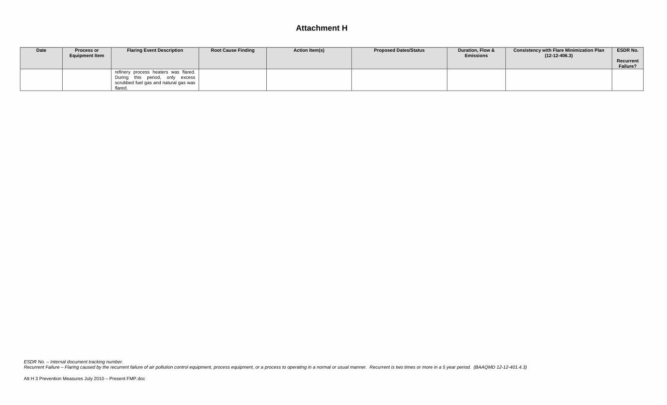
Attachment H
ESDR No. – Internal document tracking number. Recurrent Failure – Flaring caused by the recurrent failure of air pollution control equipment, process equipment, or a process to operating in a normal or usual manner. Recurrent is two times or more in a 5 year period. (BAAQMD 12-12-401.4.3) Att H 3 Prevention Measures July 2010 – Present FMP.doc
Date Process or Equipment Item
Flaring Event Description Root Cause Finding Action Item(s) Proposed Dates/Status Duration, Flow & Emissions
Consistency with Flare Minimization Plan (12-12-406.3)
ESDR No.
Recurrent Failure?
refinery process heaters was flared. During this period, only excess scrubbed fuel gas and natural gas was flared.

Flare Minimization Plan, BAAQMD 12-12 Phillips 66, San Francisco Refinery BAAQMD Plant 16
ATTACHMENT I
STORAGE, TREATMENT, & RECOVERY SCHEMATIC


Flare Minimization Plan, BAAQMD 12-12 Phillips 66, San Francisco Refinery BAAQMD Plant 16
ATTACHMENT J
(Reserved)

Flare Minimization Plan, BAAQMD 12-12 Phillips 66, San Francisco Refinery BAAQMD Plant 16
Attachment K
Flare Construction
Flare Main Flare MP30 Flare
Source No. (S-296) (S-398)
Flare Height 250’ – See Att. C 225’ – See Att C
Pipe Diameter 5’ – See Att C 4’ – See Att C
Number of Pilots 4 – See Section 2.2.3.1 4 – See Section 2.2.3.2
Number of Steam Injection Nozzles
2 steam injection headers (2” & 6”) and a Callidus BTZ-US upper steam flare tip.
2 steam injection headers (3” & 6”) and a Callidus BTZ-IS3 multiple internal steam injection system.
Capacity 1 842 ton/hr 445 ton/hr
Date of Construction
1970 approx , Tip Replaced 1996 2000
Location of Purge Gas Insertion
See Attachment B, Section titled “Main Flare Purge Gas Requirements” for details. See also Att C for placement on PFD.
See Attachment B, Section titled “MP-30 Flare Operation” for details. See also Att C for placement on PFD.
1 Capacity provided is based on expected flow from total power failure. Flare system likely able to handle larger flow. Main design factor for flare tip diameter is gas exit velocity. Generally, flares are sized to permit a velocity of up to 0.5 Mach for short-term, peak, conditions with 0.2 Mach for normal conditions.

Flare Minimization Plan, BAAQMD 12-12 Phillips 66, San Francisco Refinery BAAQMD Plant 16
Attachment L
Compressor Capacity & Monitoring Description
G-503 Flare Gas Recovery Compressor
Brand Bessemer-Cooper
Name JM-2 Compressor Unit
Serial Number 48321
Type Reciprocating
Date of Operation Mid 1970’s (approximation)
Capacity 4.75 MMSCF/D & 165 PSI (Vapor Recovery Service)
9.55 MMSCF/D (Wet Gas Service)
HP Rating 1000 HP
G-540 A/B/C Liquid Ring Flare Gas Recovery Compressors
Brand Garo
Name AB 1500 F1
Serial Number 6103 (200G540A), 6104 (200G540B), 6105 (200G540C)
Type Liquid Ring
Date of Operation August 2009 (approximate)
Capacity 4.8 MMSCF/D Vapor Recovery Service
at 15.7 psia and 110 oF
(combined capacity of three compressors)
HP Rating 600 BHP each

Flare Minimization Plan, BAAQMD 12-12 Phillips 66, San Francisco Refinery BAAQMD Plant 16
Compressor & Fuel Gas Compatibility Specification Monitoring
Monitoring is conducted at Unit 200 on the Flare Gas Recovery Compressor. The primary drivers are specific gravity monitoring and compressor loading. Both give indications of changes in the fuel gas composition (e.g. low specific gravity indicates increased H2, increased loading at compressor indicates higher N2 level in system). Prior to recovered gasses being sent to U233, if significant composition changes occur the change is mitigated by the addition of supplemental gasses. If the gas addition does not mitigate the adverse effects then the flare gas compressor is placed into recirculation or shutdown and gasses are diverted to flare. See compressor monitoring information for more details on parameters monitored.
Monitoring of fuel gas heating value is a secondary means for ensuring fuel gas specifications are met. Fuel gas is monitoring with a Houston-Atlas H2S analyzer, Wobbe Heating Value Analyzer, and specific gravity (SG) analyzers. Fuel gas gravity is monitored to allow operation within a desired range (not hard limits). Generally, at the Flare Gas Recovery Compressor, SG lower than 0.6 is not desired due to low heating value to sustain good operation. SG higher then 1.12 must be avoided to prevent condensation of liquids (C4) in the fuel gas system. Fuel gas composition is adjusted through the addition or reduction of supplemental gasses such as butane and natural gas to ensure fuel quality is met.

Flare Minimization Plan, BAAQMD 12-12 Phillips 66, San Francisco Refinery BAAQMD Plant 16
Attachment M
Fuel Gas System Overview
The fuel gas system is composed of three major components. Unit 233 Fuel Gas Cleanup, Unit 215 Merichem and Unit 246/Air Liquide Fuel Gas (RFG B). Unit 233 receives sour gas streams and cleans them up for re-use in facility combustion devices (refinery heaters and the Steam Power Plant Turbines). The feeds to Unit 233 include gasses from:
•G-503 Flare Gas Recovery Compressor
•G-540 A/B/C Flare Gas Recovery Compressors
•Unit 200 Odor Abatement Compressor
•Unit 200 Light Ends, primarily composed of gasses from G-501 Wet Gas Compressor
•Unicracker Sour Gas Make
•Units 228, 230, 231, & 215 Sour Gas
Once these gasses are cleaned, butane and natural gas is added to supplement the fuel supply. The primary considerations for fuel include pressure, sulfur content, specific gravity, and BTU content. The normal operating range for fuel gas pressure is 72 to 74 psig. The pressure is continuously monitored. As the pressure decreases below the desired pressure natural gas is automatically added. All the heaters at the facility are subject to EPA’s New Source Performance Standard (NSPS) Subpart J for combustion devices. This requires that the fuel fired to the heater not have Hydrogen Sulfide (H2S) content greater than 162 ppmv. An H2S analyzer is in place to continuously measure H2S content to ensure compliance with the limit.
Additionally, the heaters at the facility are subject to a Sulfur Dioxide (SO2) bubble as described in the Plant 16 Title V Permit Condition No. 1694. This requires that the fuel gas be sampled for Total Reduced Sulfur (TRS) three (3) times per day and that speciated sulfur sampling be performed on a monthly basis in order to calculate the SO2 emissions associated with combustion. Specific gravity (sg) monitoring is the primary means in which gas quality is assured. Adjustments are made to the amount of butane added to fuel gas to control specific gravity. There are continuous specific gravity analyzers in a number of fuel gas headers throughout the refinery. As a secondary means of monitoring there is a Wobbe analyzer which determines the higher heating value (HHV) of the fuel gas. Attachment L and Section 2.2.3.3 provides details as to the type of monitoring performed at the Flare Gas Compressor. This gas is more variable then the other feeds to Unit 233. As described in Attachment L, the flare gas recovery compressor is shutdown if the gasses being sent to the compressor are not suitable for recovery.
A slip stream from U233, after cleanup, is sent to Unit 215 Merichem for further sulfur removal. There are two heaters on site which have more stringent sulfur standards for our Ultra Low Sulfur Diesel Project requiring the fuel from Unit 233 to undergo further sulfur removal. Lastly, as part of our Clean Fuels Project we have an additional lower sulfur standard for the fuel being sent to Unit 246. This fuel termed RFG B can be a blend of natural gas, U233 gas, U215 fuel gas, and Unicracker Sweet Gas (RFG A). The Unicracker Sweet Gas is depicted on the fuel gas diagram. This is a low H2S content gas that comes off of the Unit 240-4 D-401 H2S Absorber. It is also used as hydrogen plant feed gas.
See the drawing contained in this section for a schematic of the fuel gas system. The schematic illustrates the primary gas producers and consumers. The main consumers can be grouped as follows based on fuel supply:
•Refinery Heaters – U233 Fuel Gas
•New Refinery Heaters at Unit 200 & U250 (post-2004) – U215 Merichem
•Steam Power Plant – U233 Fuel Gas, Natural Gas, Unicracker Sweet Gas
•Unit 110 Hydrogen Plant Furnace H-1 - U233 Fuel Gas, Natural Gas, Unicracker Sweet Gas
•Unit 246 Heater – RFG B Fuel Gas or individual fuel components

Flare Minimization Plan, BAAQMD 12-12 Phillips 66, San Francisco Refinery BAAQMD Plant 16
Attachment N
Cost Effectiveness Calculation Background Material

Flare Minimization Plan, BAAQMD 12-12 Phillips 66, San Francisco Refinery BAAQMD Plant 16
Cost Curves for Major Equipment


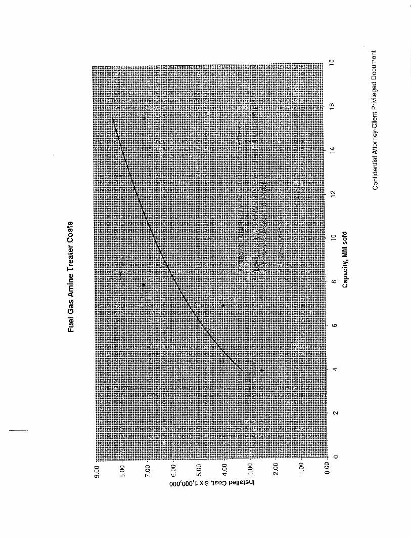


Flare Minimization Plan, BAAQMD 12-12 Phillips 66, San Francisco Refinery BAAQMD Plant 16
Cost Effective & Emission Calculations for
Storage, Treatment, and Recovery Cases 1 – 4