Flame Tracker* Lite
14
Flame Tracker* Lite SiC Flame Sensor Reuter-Stokes Operation and Maintenance Manual FS-9100OM Rev. B October 2020 * A trademark of Baker Hughes Holdings LLC ©2020 Baker Hughes Holdings LLC. All rights reserved. Technical content subject to change without notice.
Transcript of Flame Tracker* Lite
Flame Tracker* Lite
SiC Flame Sensor Reuter-Stokes
Operation and Maintenance Manual
FS-9100OM Rev. B October 2020
* A trademark of Baker Hughes Holdings LLC ©2020 Baker Hughes Holdings LLC. All rights reserved.
Technical content subject to change without notice.
i Copyright 2020 Baker Hughes Holdings LLC. All rights reserved
NOTICE
All content and material in this Manual (including, without limitation, text, design, graphics, logos, icons,
images, code and software, as well as the selection and arrangement thereof) is confidential and proprietary,
the exclusive property of and owned by Reuter-Stokes, LLC. and is protected by copyright, trademark and
other applicable laws. Any use of content and material in this Manual, including but not limited to the
modification, distribution, transmission, performance, broadcast, publication, uploading, licensing, reverse
engineering, transfer or sale of, or the creation of derivative works from, any material, information, software,
products or services obtained from the content and material in this Manual, or use thereof for purposes
competitive to Reuter-Stokes, LLC, is expressly prohibited.
WHILE EVERY ATTEMPT HAS BEEN MADE TO ASSURE THE COMPLETENESS, ACCURACY AND
TIMELINESS OF THE CONTENT AND MATERIAL IN THIS MANUAL, IT IS PROVIDED ON AN "AS IS" AND "AS
AVAILABLE" BASIS. REUTER-STOKES, LLC. EXPRESSLY DISCLAIMS ALL WARRANTIES OF ANY KIND,
WHETHER EXPRESS OR IMPLIED, INCLUDING BUT NOT LIMITED TO THE IMPLIED WARRANTIES OF
MERCHANTABILITY AND FITNESS FOR A PARTICULAR PURPOSE AND ANY WARRANTIES THAT THE
CONTENT AND MATERIAL IN THIS MANUAL IS NONINFRINGING, AS WELL AS WARRANTIES IMPLIED
FROM A COURSE OF PERFORMANCE OR COURSE OF DEALING; THE MATERIALS IN THIS MANUAL WILL
BE ERROR-FREE; OR THAT THE MATERIALS IN THIS MANUAL WILL BE COMPLETE, ACCURATE OR
TIMELY. NO ADVICE OR INFORMATION, OBTAINED BY YOU FROM REUTER-STOKES, LLC. OR THROUGH
THE CONTENT AND MATERIAL IN THIS MANUAL SHALL CREATE ANY WARRANTY OF ANY KIND. REUTER-
STOKES, LLC. DOES NOT MAKE ANY WARRANTIES OR REPRESENTATIONS REGARDING THE USE OF
THE CONTENT AND MATERIAL IN THIS MANUAL IN TERMS OF THEIR COMPLETENESS, CORRECTNESS,
ACCURACY, ADEQUACY, USEFULNESS, TIMELINESS, RELIABILITY OR OTHERWISE.
YOU ACKNOWLEDGE AND AGREE THAT YOU ASSUME FULL RESPONSIBILITY FOR YOUR USE OF THE
CONTENT AND MATERIAL IN THIS MANUAL. YOU ACKNOWLEDGE AND AGREE THAT YOUR USE OF THE
CONTENT AND MATERIAL IN THIS MANUAL IS AT YOUR OWN RISK. YOU ACKNOWLEDGE AND AGREE
THAT, TO THE FULLEST EXTENT PERMITTED BY APPLICABLE LAW, REUTER-STOKES, LLC. WILL NOT
BE LIABLE FOR ANY DIRECT, INDIRECT, PUNITIVE, EXEMPLARY, INCIDENTAL, SPECIAL,
CONSEQUENTIAL OR OTHER DAMAGES ARISING OUT OF OR IN ANY WAY RELATED TO THE CONTENT
AND MATERIAL IN THIS MANUAL, WHETHER BASED ON CONTRACT, TORT, STRICT LIABILITY OR
OTHERWISE. THIS DISCLAIMER APPLIES, WITHOUT LIMITATION, TO ANY DAMAGES OR INJURY ARISING
FROM ANY FAILURE OF PERFORMANCE, ERROR, OMISSION, YOUR LOSS OF PROFITS, DESTRUCTION,
AND ANY OTHER TANGIBLE OR INTANGIBLE LOSS.
Copyright © 2020 Baker Hughes Holdings LLC.
Contains Baker Hughes Holdings LLC Confidential Information.
FS-9100OM – REV B
ii
Copyright 2020 Baker Hughes Holdings LLC. All rights reserved
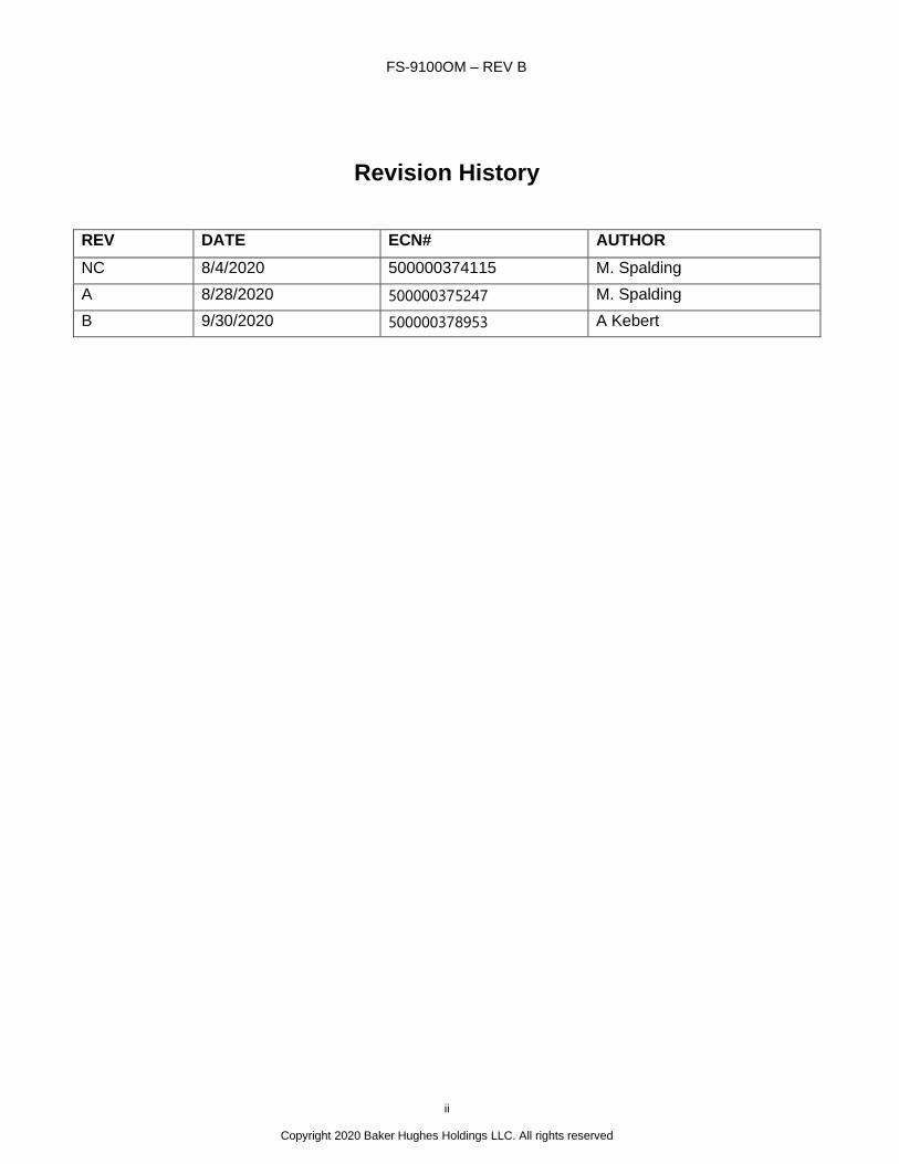
Revision History
REV DATE ECN# AUTHOR
NC 8/4/2020 500000374115 M. Spalding
A 8/28/2020 500000375247 M. Spalding
B 9/30/2020 500000378953 A Kebert
FS-9100OM – REV B
iii
Copyright 2020 Baker Hughes Holdings LLC. All rights reserved
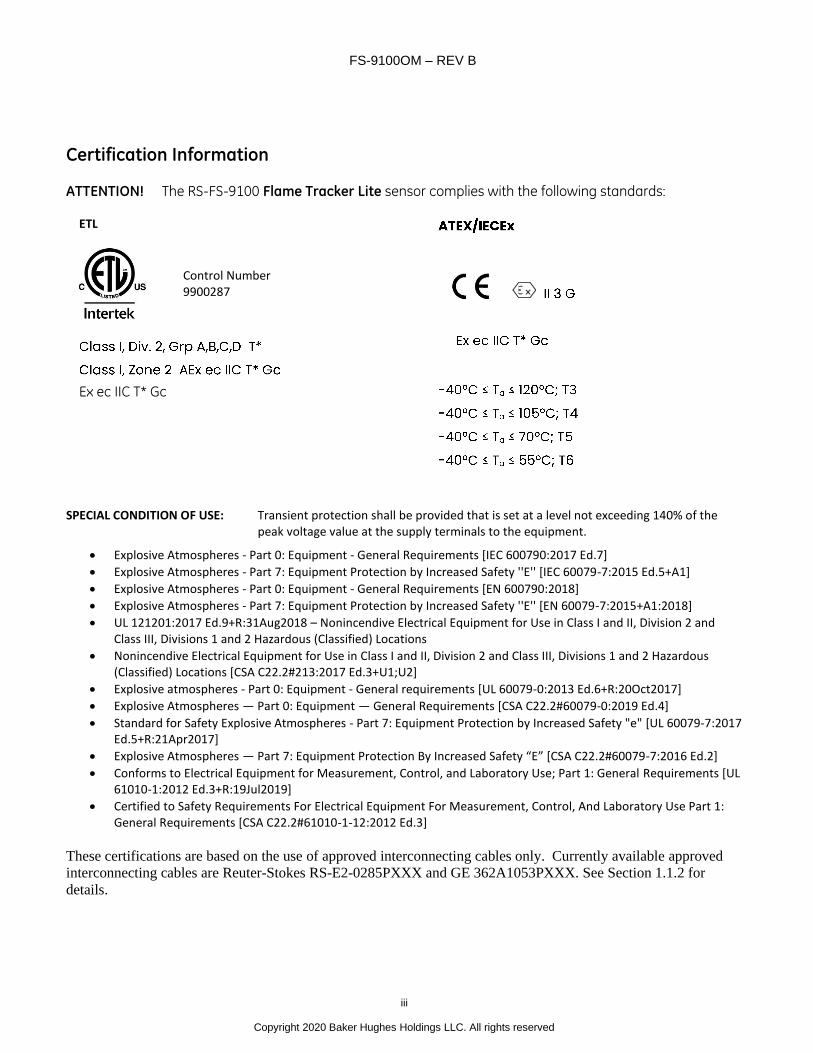
Certification Information ATTENTION! The RS-FS-9100 Flame Tracker Lite sensor complies with the following standards:
ETL
Ex ec IIC T* Gc
SPECIAL CONDITION OF USE: Transient protection shall be provided that is set at a level not exceeding 140% of the
peak voltage value at the supply terminals to the equipment.
• Explosive Atmospheres - Part 0: Equipment - General Requirements [IEC 600790:2017 Ed.7]
• Explosive Atmospheres - Part 7: Equipment Protection by Increased Safety ''E'' [IEC 60079-7:2015 Ed.5+A1]
• Explosive Atmospheres - Part 0: Equipment - General Requirements [EN 600790:2018]
• Explosive Atmospheres - Part 7: Equipment Protection by Increased Safety ''E'' [EN 60079-7:2015+A1:2018]
• UL 121201:2017 Ed.9+R:31Aug2018 – Nonincendive Electrical Equipment for Use in Class I and II, Division 2 and Class III, Divisions 1 and 2 Hazardous (Classified) Locations
• Nonincendive Electrical Equipment for Use in Class I and II, Division 2 and Class III, Divisions 1 and 2 Hazardous (Classified) Locations [CSA C22.2#213:2017 Ed.3+U1;U2]
• Explosive atmospheres - Part 0: Equipment - General requirements [UL 60079-0:2013 Ed.6+R:20Oct2017]
• Explosive Atmospheres — Part 0: Equipment — General Requirements [CSA C22.2#60079-0:2019 Ed.4]
• Standard for Safety Explosive Atmospheres - Part 7: Equipment Protection by Increased Safety "e" [UL 60079-7:2017 Ed.5+R:21Apr2017]
• Explosive Atmospheres — Part 7: Equipment Protection By Increased Safety “E” [CSA C22.2#60079-7:2016 Ed.2]
• Conforms to Electrical Equipment for Measurement, Control, and Laboratory Use; Part 1: General Requirements [UL 61010-1:2012 Ed.3+R:19Jul2019]
• Certified to Safety Requirements For Electrical Equipment For Measurement, Control, And Laboratory Use Part 1: General Requirements [CSA C22.2#61010-1-12:2012 Ed.3]
These certifications are based on the use of approved interconnecting cables only. Currently available approved
interconnecting cables are Reuter-Stokes RS-E2-0285PXXX and GE 362A1053PXXX. See Section 1.1.2 for
details.
Control Number 9900287
FS-9100OM – REV B
iv
Copyright 2020 Baker Hughes Holdings LLC. All rights reserved
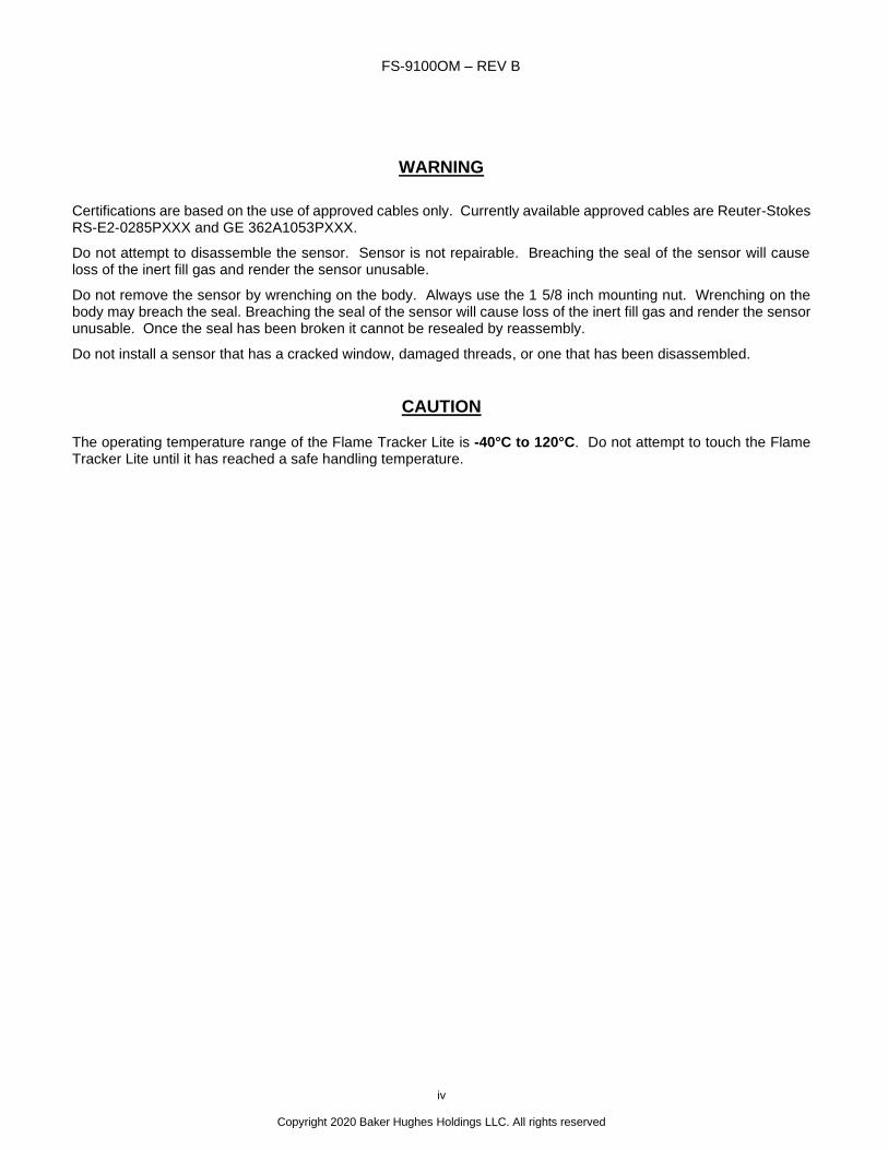
WARNING
Certifications are based on the use of approved cables only. Currently available approved cables are Reuter-Stokes RS-E2-0285PXXX and GE 362A1053PXXX.
Do not attempt to disassemble the sensor. Sensor is not repairable. Breaching the seal of the sensor will cause loss of the inert fill gas and render the sensor unusable.
Do not remove the sensor by wrenching on the body. Always use the 1 5/8 inch mounting nut. Wrenching on the body may breach the seal. Breaching the seal of the sensor will cause loss of the inert fill gas and render the sensor unusable. Once the seal has been broken it cannot be resealed by reassembly.
Do not install a sensor that has a cracked window, damaged threads, or one that has been disassembled.
CAUTION
The operating temperature range of the Flame Tracker Lite is -40°C to 120°C. Do not attempt to touch the Flame Tracker Lite until it has reached a safe handling temperature.
FS-9100OM – REV B
v
Copyright 2020 Baker Hughes Holdings LLC. All rights reserved
TABLE OF CONTENTS 1 INTRODUCTION .................................................................................................................................................. 1
1.1 SPECIFICATIONS ..............................................................................................................................................1 1.1.1 FLAME TRACKER LITE RS-FS-9100 .........................................................................................................1 1.1.2 INTERCONNECTING CABLE RS-E2-0285PXXX OR 362A1053PXXX .....................................................2
1.2 REFERENCE......................................................................................................................................................3 1.3 GENERAL DESCRIPTION .................................................................................................................................4
2 INSTALLATION .................................................................................................................................................... 4 2.1 MECHANICAL ....................................................................................................................................................4 2.2 ELECTRICAL......................................................................................................................................................4 2.3 CONNECTOR PINOUT ......................................................................................................................................7 2.4 SENSOR CHECKOUT .......................................................................................................................................7 2.5 CONTROLLER SETUP ......................................................................................................................................7
3 MAINTENANCE ................................................................................................................................................... 7 3.1 WARNING ..........................................................................................................................................................7 3.2 CAUTION ............................................................................................................................................................7
4 TROUBLESHOOTING ......................................................................................................................................... 8 4.1 WARNING ..........................................................................................................................................................8 4.2 CAUTION ............................................................................................................................................................8
FS-9001OM – REV B
1 Copyright 2020 Baker Hughes Holdings LLC. All rights reserved
1 INTRODUCTION
1.1 SPECIFICATIONS
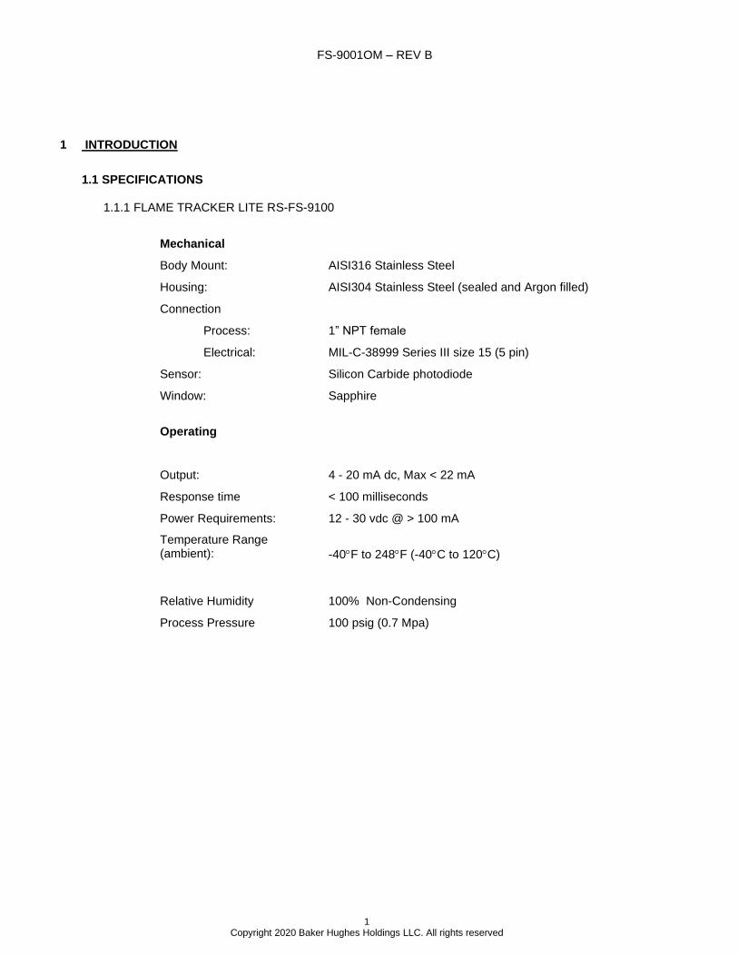
1.1.1 FLAME TRACKER LITE RS-FS-9100
Mechanical
Body Mount: AISI316 Stainless Steel
Housing: AISI304 Stainless Steel (sealed and Argon filled)
Connection
Process: 1” NPT female
Electrical: MIL-C-38999 Series III size 15 (5 pin)
Sensor: Silicon Carbide photodiode
Window: Sapphire
Operating
Output: 4 - 20 mA dc, Max < 22 mA
Response time < 100 milliseconds
Power Requirements: 12 - 30 vdc @ > 100 mA
Temperature Range (ambient):
-40F to 248F (-40C to 120C)
Relative Humidity
Process Pressure
100% Non-Condensing
100 psig (0.7 Mpa)
FS-9100OM – REV B
2
Copyright 2020 Baker Hughes Holdings LLC. All rights reserved
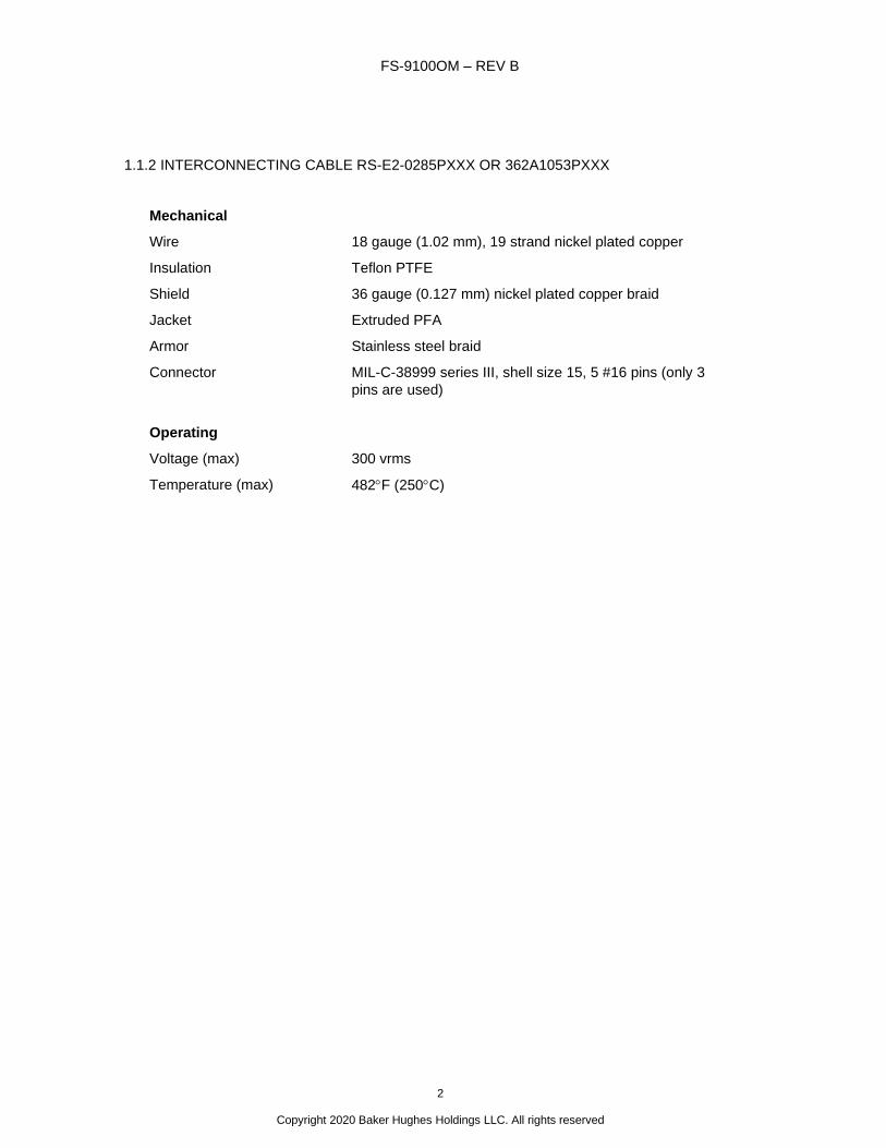
1.1.2 INTERCONNECTING CABLE RS-E2-0285PXXX OR 362A1053PXXX
Mechanical
Wire 18 gauge (1.02 mm), 19 strand nickel plated copper
Insulation Teflon PTFE
Shield
Jacket
36 gauge (0.127 mm) nickel plated copper braid
Extruded PFA
Armor Stainless steel braid
Connector MIL-C-38999 series III, shell size 15, 5 #16 pins (only 3
pins are used)
Operating
Voltage (max) 300 vrms
Temperature (max) 482F (250C)

FS-9100OM – REV B
3
Copyright 2020 Baker Hughes Holdings LLC. All rights reserved
1.2 REFERENCE
FS-9100OM – REV B
4
Copyright 2020 Baker Hughes Holdings LLC. All rights reserved
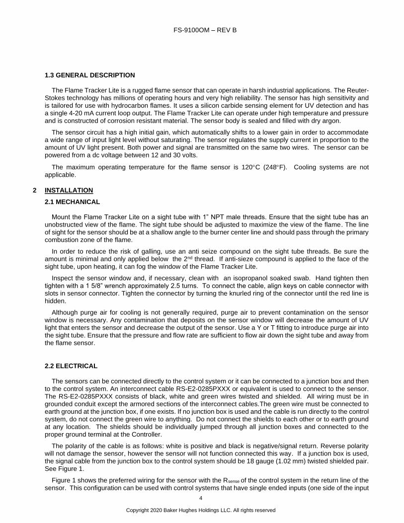
1.3 GENERAL DESCRIPTION
The Flame Tracker Lite is a rugged flame sensor that can operate in harsh industrial applications. The Reuter-Stokes technology has millions of operating hours and very high reliability. The sensor has high sensitivity and is tailored for use with hydrocarbon flames. It uses a silicon carbide sensing element for UV detection and has a single 4-20 mA current loop output. The Flame Tracker Lite can operate under high temperature and pressure and is constructed of corrosion resistant material. The sensor body is sealed and filled with dry argon.
The sensor circuit has a high initial gain, which automatically shifts to a lower gain in order to accommodate a wide range of input light level without saturating. The sensor regulates the supply current in proportion to the amount of UV light present. Both power and signal are transmitted on the same two wires. The sensor can be powered from a dc voltage between 12 and 30 volts.
The maximum operating temperature for the flame sensor is 120C (248F). Cooling systems are not applicable.
2 INSTALLATION
2.1 MECHANICAL
Mount the Flame Tracker Lite on a sight tube with 1” NPT male threads. Ensure that the sight tube has an unobstructed view of the flame. The sight tube should be adjusted to maximize the view of the flame. The line of sight for the sensor should be at a shallow angle to the burner center line and should pass through the primary combustion zone of the flame.
In order to reduce the risk of galling, use an anti seize compound on the sight tube threads. Be sure the amount is minimal and only applied below the 2nd thread. If anti-sieze compound is applied to the face of the sight tube, upon heating, it can fog the window of the Flame Tracker Lite.
Inspect the sensor window and, if necessary, clean with an isopropanol soaked swab. Hand tighten then tighten with a 1 5/8” wrench approximately 2.5 turns. To connect the cable, align keys on cable connector with slots in sensor connector. Tighten the connector by turning the knurled ring of the connector until the red line is hidden.
Although purge air for cooling is not generally required, purge air to prevent contamination on the sensor window is necessary. Any contamination that deposits on the sensor window will decrease the amount of UV light that enters the sensor and decrease the output of the sensor. Use a Y or T fitting to introduce purge air into the sight tube. Ensure that the pressure and flow rate are sufficient to flow air down the sight tube and away from the flame sensor.
2.2 ELECTRICAL
The sensors can be connected directly to the control system or it can be connected to a junction box and then to the control system. An interconnect cable RS-E2-0285PXXX or equivalent is used to connect to the sensor. The RS-E2-0285PXXX consists of black, white and green wires twisted and shielded. All wiring must be in grounded conduit except the armored sections of the interconnect cables.The green wire must be connected to earth ground at the junction box, if one exists. If no junction box is used and the cable is run directly to the control system, do not connect the green wire to anything. Do not connect the shields to each other or to earth ground at any location. The shields should be individually jumped through all junction boxes and connected to the proper ground terminal at the Controller.
The polarity of the cable is as follows: white is positive and black is negative/signal return. Reverse polarity will not damage the sensor, however the sensor will not function connected this way. If a junction box is used, the signal cable from the junction box to the control system should be 18 gauge (1.02 mm) twisted shielded pair. See Figure 1.
Figure 1 shows the preferred wiring for the sensor with the Rsense of the control system in the return line of the sensor. This configuration can be used with control systems that have single ended inputs (one side of the input

FS-9100OM – REV B
5
Copyright 2020 Baker Hughes Holdings LLC. All rights reserved
grounded) or differential inputs (neither side of the input grounded). For pin outs and cable color code see Table 1 in section 2.3.
Flame Tracker LiteSENSOR PART NO.
RS-FS-9100
C A B
SENSOR CABLE
RS-E2-0285PXXX
GE 362A1053PXXX
Run in grounded conduit
+Vdc
Signal
R
-Vdc
Shield GND
sense V = I X Rsenseout
EXTENSION CABLE
18 gauge, twisted shielded pair
Run in grounded conduit
JUNCTION BOX
Local ground if present. Do no
connect outside ground potential of
fired equipment
FIGURE 1 - FLAME SENSOR WIRING DIAGRAM
FS-9100OM – REV B
6
Copyright 2020 Baker Hughes Holdings LLC. All rights reserved
The Flame Tracker Lite is connected to the control system as a typical two wire current transmitter. It can be operated from any well-filtered dc supply from 12 volts to 30 volts. The supply should be capable of supplying 100 milliamps.
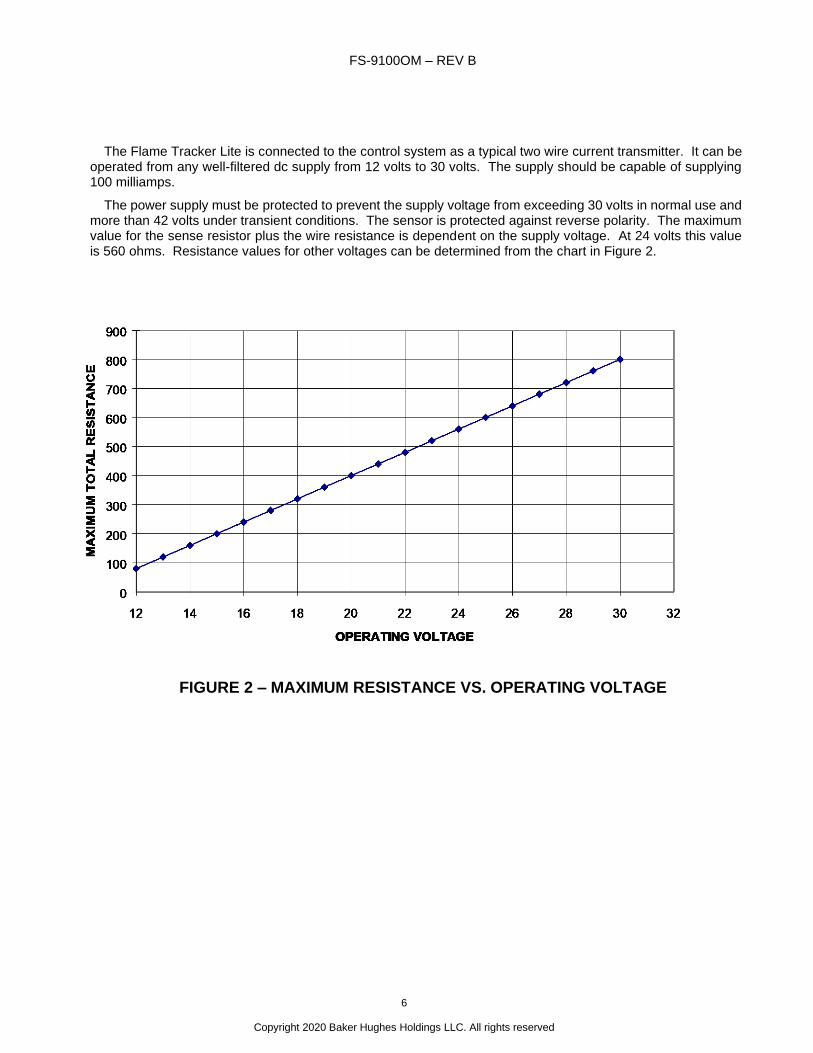
The power supply must be protected to prevent the supply voltage from exceeding 30 volts in normal use and more than 42 volts under transient conditions. The sensor is protected against reverse polarity. The maximum value for the sense resistor plus the wire resistance is dependent on the supply voltage. At 24 volts this value is 560 ohms. Resistance values for other voltages can be determined from the chart in Figure 2.
FIGURE 2 – MAXIMUM RESISTANCE VS. OPERATING VOLTAGE

FS-9100OM – REV B
7
Copyright 2020 Baker Hughes Holdings LLC. All rights reserved
2.3 CONNECTOR PINOUT
The pinout for the power connector is as follows:
Table 1
Interconnecting Cable Pinout
PIN CIRCUIT DESIGNATION WIRE COLOR
A - Black
B + White
C Ground Green
D Not Used
E Not Used
2.4 SENSOR CHECKOUT
A UV light source in the range of 200-400 nm is required to test the Flame Tracker Lite. Many LED flashlights do not emit UV light. Incandescent flashlights will work. A good solution is a light that is specifically made to emit UV light, such as the Streamlight Stylus UV pen light, manufacturer part number 65069.
Disconnect the sensors and unscrew them from the sight tubes. Plug the sensor cables back in to each of the sensors. Apply power to the sensors. Check the current values at the control system for each of the sensors. The sensors are sensitive to light, and may have some reading, depending on the ambient light intensity and UV content. Test each sensor by covering the window to see the zero flame intensity signals, and with a UV light to see a positive reading. With no UV light the reading should be 3.7 to 4.1 milliamps and with most flashlights the reading should be above 8 milliamps. Variations in light type, strength, or battery voltage may cause variation in signal output. The test is intended as a field test for general functionality only and is not a controlled or quantitative test. If a sensor is outside these rough check limits see Section 4 Troubleshooting.
Disconnect the sensor cables, and reinstall the sensors according to the instruction in Section 2.1.
2.5 CONTROLLER SETUP
The Flame Tracker Lite is very sensitive to hydrocarbon and other types of flames. It will output 4 mA for no UV light and will output a maximum of 22 mA for high intensity UV light, although most outputs will be within the range of 4-20 mA. Milliamp threshold values for Flame On/Off determination should be stored in the control system. Some control systems will use a single threshold value and 5.0 mA is typical. Some control system use hysteresis and have two thresholds, one for Flame On and one for Flame Off. 5.0 mA and 6.0 mA are typical values for such control systems.
3 MAINTENANCE
3.1 WARNING
Do not disconnect the cable connector while circuit is energized (or live), unless area is known to be non-hazardous.
3.2 CAUTION
The operating temperature range of the Flame Sensor is -40°C to 120°C. Do not attempt to touch the Flame Tracker Lite or the cable until they have reached a safe handling temperature.
The flame sensor output will deteriorate as the lens becomes dirty. It is recommended, when initially installed, that the signal level be recorded during normal operation. During subsequent operation, the signal level should
FS-9100OM – REV B
8
Copyright 2020 Baker Hughes Holdings LLC. All rights reserved
be compared with the initial values. If a significant reduction in the signal level is noticed, then it is recommended that the lens be cleaned at the next opportunity (with the fired equipment shut down and cold). Clean the sensor window with isopropyl alcohol or other residue free solvent compatible with sapphire. Apply a small amount of anti-sieze compound to threads of sight tube prior to installation. Be sure the amount is minimal and only applied below the 2nd thread. If anti-sieze compound is applied to the face of the sight tube, upon heating, it can fog the window of the Flame Tracker Lite.
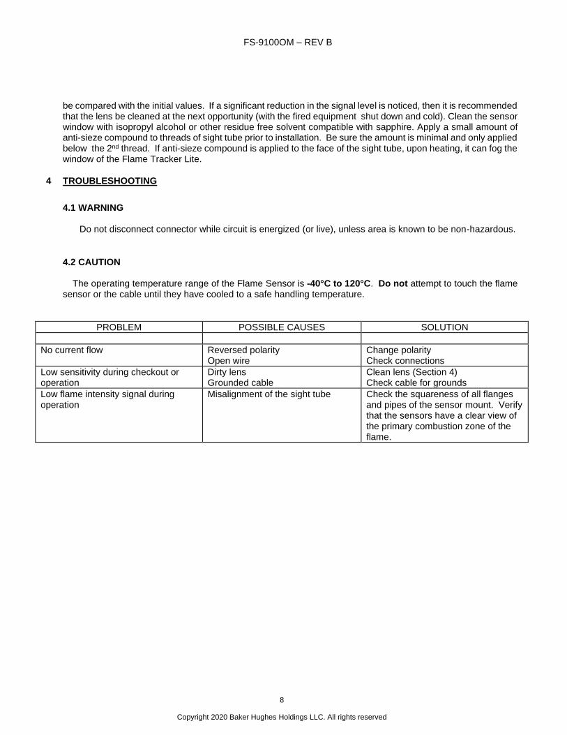
4 TROUBLESHOOTING
4.1 WARNING
Do not disconnect connector while circuit is energized (or live), unless area is known to be non-hazardous.
4.2 CAUTION
The operating temperature range of the Flame Sensor is -40°C to 120°C. Do not attempt to touch the flame sensor or the cable until they have cooled to a safe handling temperature.
PROBLEM POSSIBLE CAUSES SOLUTION
No current flow Reversed polarity Open wire
Change polarity Check connections
Low sensitivity during checkout or operation
Dirty lens Grounded cable
Clean lens (Section 4) Check cable for grounds
Low flame intensity signal during operation
Misalignment of the sight tube Check the squareness of all flanges and pipes of the sensor mount. Verify that the sensors have a clear view of the primary combustion zone of the flame.