Fixture Accessories - Mekan · Fixture Accessories ... TestJet & VTEP Parts for Agilent 3070...
36
EVERETT CHARLES TECHNOLOGIES C O N T A C T P R O D U C T S G R O U P M U N I C H FIXTURE ACCESSORIES Mass Interconnect Products Opens Testing Products LEDCHECK Parts Board Marker Probes Personality Pins Indicator Probes Test Connectors
Transcript of Fixture Accessories - Mekan · Fixture Accessories ... TestJet & VTEP Parts for Agilent 3070...

EVERETT CHARLESTECHNOLOGIES
C o n t a C t P r o d u C t s G r o u P M u n i C h
Fixture Accessories
Mass Interconnect ProductsOpens Testing ProductsLEDCHECK PartsBoard Marker ProbesPersonality PinsIndicator ProbesTest Connectors

VG Receiver . . . . . . . . . . . . . . . . . . . . . . . . . . . . . . . 7Coax VG Blocks . . . . . . . . . . . . . . . . . . . . . . . . . . . . 8Coax VG Blocks . . . . . . . . . . . . . . . . . . . . . . . . . . . . 8Coax VG Blocks . . . . . . . . . . . . . . . . . . . . . . . . . . . . 8Combi Coax / Power Blocks . . . . . . . . . . . . . . . . . . . 9Combi Coax / Power Blocks . . . . . . . . . . . . . . . . . . . 9Combi Coax / Power Blocks . . . . . . . . . . . . . . . . . . . 9Combi Coax / Power Blocks . . . . . . . . . . . . . . . . . . 10Combi Coax / Power Blocks . . . . . . . . . . . . . . . . . . 10Combi Coax / Power Blocks . . . . . . . . . . . . . . . . . . 10Coax / Power / Signal / Pneumatic Blocks . . . . . . . . 11Power Blocks . . . . . . . . . . . . . . . . . . . . . . . . . . . . . 11Pneumatic Blocks . . . . . . . . . . . . . . . . . . . . . . . . . 11Signal VG Blocks . . . . . . . . . . . . . . . . . . . . . . . . . . 12Signal VG Blocks . . . . . . . . . . . . . . . . . . . . . . . . . . 12Vacuum Port Modules / Tools . . . . . . . . . . . . . . . . 13
TestJet & VTEP Parts for Agilent 3070 fixtures . . . 17OpensXpress Parts for GenRad fixtures . . . . . . . . . 21 . . . . . . . . . . . . . . . . . . . . . . . . . . . . . . . . . . . . . . . 22
Analog LEDCHECK VIII . . . . . . . . . . . . . . . . . . . . . . 26Analog LEDCHECK VIII Accessories . . . . . . . . . . . . 27Digital LEDCHECK III & V . . . . . . . . . . . . . . . . . . . . 28Digital LEDCHECK Accessories . . . . . . . . . . . . . . . 29 . . . . . . . . . . . . . . . . . . . . . . . . . . . . . . . . . . . . . . . 30 . . . . . . . . . . . . . . . . . . . . . . . . . . . . . . . . . . . . . . . 31Floating Test Connectors . . . . . . . . . . . . . . . . . . . . 32Floating Test Connectors . . . . . . . . . . . . . . . . . . . . 33Floating Test Connectors . . . . . . . . . . . . . . . . . . . . 34
VGR4 / VGR12 / VGR12-RM1 / VGR24 / VGR24-RM1VGRCB-4C / VGFCB-4CVGRCB-9C / VGFCB-9CVGRCB-13C / VGFCB-13CVGRCB-13CPF / VGFCB-13CPFVGRCB-15CPF / VGFCB-15CPFVGRCB-22CPF / VGFCB-22CPFVGRCB-24CPF / VGFCB-24CPFVGRCB-30CPF / VGFCB-30CPFVGRCB-32CPF / VGFCB-32CPFVGRCB-39CPS / VGFCB-39CPSVGRCB-32P / VGFCB-32PVGRCB-13PNEU / VGFCB-13PNEUVGRCB-136 / VGFCB-136VGRCB-170 / VGFCB-170VGRCB-VPM / VGFCB-VPM / Tools
Agilent TestJet PartsGenRad OpensXpress PartsTeradyne: FrameScan Plus & FrameScan FX 2 .0 Parts
Analog Color AnalyserAnalog Color AnalyserDigital Color AnalyserDigital Color AnalyserBoard Marker ProbePersonality Pins for Agilent Fixtures / Indicator ProbeHDMI ConnectorMini Western ConnectorsUSB Connectors
Mass interconnect Products
opens testing Products
special Products
Table of ConTenTs


MAss interconnect Products

6 Dimensions in inches (millimeters)Specifications subject to change without notice
Mass Interconnect Products
The VG Series products are designed for Mass Interconnect termina-tions of Rack & Stack test systems .
There are several VG receiver available which will accept any fixtures with a Pylon Interface . Such fixtures are also available from ECT in different sizes .
Although someone might say with a smile that “VG” stands for “Very Good”, whereas the right abbreviation VG is:
“V”: VXI (Vme Xtensions for Instrumentation) and
“G”: GPIB (General Purpose Instrument Bus/ HPIB / IEEE-488) .
there are a number of different block types: “Coax: up to 18 GHz
“Power: up to 50 Amps per pin
“Coax & Power combined
“Signal: up to 170 pins, @250VAC/5 Amps
“Pneumatic: up to 13 fittings
“Vacuum: port modules
Other blocks or cable assemblies are available upon request; please contact your closest ECT location .
These products were developed and produced by TTI-Testron, which was acquired by ECT in 1999 . Since then ECT continued to provide the VG Series Mass Interconnect product through their worldwide distribu-tion channels .
Typical industry applications are for example Aircraft, Military, Medical, Consumer Electronics, Networking, Telecommunications and Test Systems…
Mass InTerConneCT ProduCTs

7Dimensions in inches (millimeters)Specifications subject to change without notice
Mas
s In
terc
onne
ct P
rodu
cts
VGr4 / VGr12 / VGr12-rM1 / VGr24 / VGr24-rM1
24 Block Double-Row Desktop Receiver
Model Number: VGR24
P/No: 207
The VGR24 will accommo-date up to 22 receiver blocks and a max . of 2 vacuum port modules in the bottom or top row .
24 Block Double-Row Rack Mount Receiver
Model Number: VGR24-RM1
P/No: 206
Same as above VGR24 but for mounting in a 19” Rack .
Dimensions of the Rack Mount Receivers VGR12-RM1 and VGR24-RM1
VG Receiver
Mini 4 Block Desktop Receiver
Model Number: VGR4
P/No: 122
To be used for small bench-top test requirements with max . 4 receiver blocks .
No vacuum port module to be used .
For the fixture side a metal Adapter Box VGF4-0808-AB (P/No 123), size 8x8” (203 x 203mm) is available .
12 Block Desktop Receiver
Model Number: VGR12
P/No: 21
To be used for all fixtures with a Pylon interface (GenRad, ITA, R&S) .
Up to 10 VG receiver blocks and max . 2 vacuum port modules can be installed .
Vacuum port module to be ordered separately VGRCB-VPM (P/No 576) .
12 Block Rack Mount Receiver
Model Number: VGR12-RM1
P/No: 140
Same as above VGR12 but for mounting in a 19” Rack
*
Cab
les
Handle mountedinside side panel
near front
12-13"(305-330 mm)
VGR12-RM1 / VGR24-RM1Dimensions
Cables
Cables
CabinetMounting
Rail
VXI Module
VXI Mainframe
VXI Mainframe
* VGR24-RM1 ADDS AN ADDITIONAL 2U TO THE HEIGHT1U = 1.75" (1U = 44,5 mm)
MountingFlangefoldedinward
6U
2U

8 Pictures show assembled VG-BlocksSpecifications subject to change without notice
reCeIver sIde fIxTure sIdeMass Interconnect Products
Coax VG BlocksVGrcB-4c / VGFcB-4cVGrcB-9c / VGFcB-9cVGrcB-13c / VGFcB-13c
13-Position up to 3.7 GHz Block
Model Number VGFCB-13C P/No 483 Impedance 50 Ω
it includes2 installed bushings 2 screws 4-40 13 installed coax contacts
Replacement Coax Fixture probe • P/No 481
13-Position up to 3.7 GHz Block
Model Number VGRCB-13C P/No 482 Impedance 50 Ω
it includes2 installed alignment pins 2 installed floating mounting screws 13 installed coax contacts
(The center conductor and the outer shell are spring loaded)
Replacement Coax Receiver probe: • P/No 480
Replacement center probe: A35860•
9-Position up to 18 GHz Block
Model Number VGFCB-9C P/No 1122 Impedance 50 Ω
it includes2 installed bushings 2 screws 4-40 9 holes (without contacts)
the coax 50 Ω blind mate jack con-tacts must be ordered separately
for crimp connection: A31898• for SMA connection: A32434•
9-Position up to 18 GHz Block
Model Number VGRCB-9C P/No 1121 Impedance 50 Ω
it includes2 installed alignment pins 2 installed floating mounting screws 9 holes (without contacts)
the coax 50 Ω blind mate plug con-tacts must be ordered separately
for crimp connection: A31897• for SMA connection: A35764•
4-Position up to 18 GHz Block
Model Number VGFCB-4C P/No 610 Impedance 50 Ω
it includes2 installed bushings 2 screws 4-40 4 holes (without contacts)
the coax contacts must be ordered separately under P/no a32434(50 Ω blind mate jack contact for a SMA connector)
4-Position up to 18 GHz Block
Model Number VGRCB-4C P/No 611 Impedance 50 Ω
it includes2 installed alignment pins 2 installed floating mounting screws 4 holes (without contacts)
the coax contacts must be ordered separately under P/no a32433(50 Ω blind mate plug contact for a SMA connector)

9Pictures show assembled VG-BlocksSpecifications subject to change without notice
reCeIver sIde fIxTure sIde
Mas
s In
terc
onne
ct P
rodu
cts
Combi Coax / Power Blocks VGrcB-13cPF / VGFcB-13cPFVGrcB-15cPF / VGFcB-15cPFVGrcB-22cPF / VGFcB-22cPF
13-Position 50 Ω Coax/Power Block
Model Number VGFCB-13CPF P/No 579 Coax contact up to 500 MHz Power contact up to 30 Amps
it includes2 installed bushings 2 screws 4-40 13 holes (without contacts)
Contacts must be ordered separatelyCoax contact with 36” coax cable •
CF-CA50RG174-36 P/No 623Power contact •
- CF-610115102 for 10 AWG - CF-610115103 for 12 AWG
13-Position 50 Ω Coax/Power Block
Model Number VGRCB-13CPF P/No 580 Coax contact up to 500 MHz Power contact up to 30 Amps
it includes2 installed alignment pins 2 installed floating mounting screws 13 holes (without contacts)
Contacts must be ordered separatelyCoax contact with 36” coax cable •
CR-CA50RG174-36 P/No 637Power contact •
- CR-610116102
15-Position 50 Ω Coax/Power Block
Model Number VGRCB-15CPF P/No 910 Coax contact up to 500 MHz Power contact up to 30 Amps
it includes2 installed alignment pins 2 installed floating mounting screws 15 holes (without contacts)
Contacts must be ordered separatelyCoax contact with 36” coax cable •
CR-CA50RG174-36 P/No 637Power contact •
- CR-610116102
15-Position 50 Ω Coax/Power Block
Model Number VGFCB-15CPF P/No 911 Coax contact up to 500 MHz Power contact up to 30 Amps
it includes2 tooling holes 2 screws 4-40 15 holes (without contacts)
Contacts must be ordered separatelyCoax contact with 36” coax cable •
CF-CA50RG174-36 P/No 623Power contact •
- CF-610115102 for 10 AWG - CF-610115103 for 12 AWG
22-Position 50 Ω Coax/Power Block
Model Number VGFCB-22CPF P/No 528 Coax contact up to 1 GHz Power contact up to 50 Amps/250 VAC
it includes2 installed bushings 2 screws 4-40 22 holes (without contacts)
Contacts must be ordered separatelyMini coax contact 610103115 or• Coax contact with 36” coax cable •
CF-CA50RG174-36: P/No 632Mini power contact CF-0883011-02•
22-Position 50 Ω Coax/Power Block
Model Number VGRCB-22CPF P/No 527 Coax contact up to 1 GHz Power contact up to 50 Amps/250 VAC
it includes2 installed alignment pins 2 installed floating mounting screws 22 holes (without contacts)
Contacts must be ordered separatelyMini coax contact 610104114 or• Coax contact with 36” coax cable •
CR-CA50RG174-36: P/No 643Mini power contact CR-610116112•

10 Pictures show assembled VG-BlocksSpecifications subject to change without notice
reCeIver sIde fIxTure sIdeMass Interconnect Products
Combi Coax / Power Blocks
32-Position 50 Ω Coax/Power Block
Model Number VGFCB-32CPF P/No 907 Coax contact up to 1 GHz Power contact up to 50 Amps/250 VAC
it includes2 installed bushings 2 screws 4-40 32 holes (without contacts)
Contacts must be ordered separatelyMini coax contact 610103115 or• Coax contact with 36” coax cable •
CF-CA50RG174-36: P/No 632Mini power contact CF-0883011-02•
32-Position 50 Ω Coax/Power Block
Model Number VGRCB-32CPF P/No 906 Coax contact up to 1 GHz Power contact up to 50 Amps/250 VAC
it includes2 installed alignment pins 2 installed floating mounting screws 32 holes (without contacts)
Contacts must be ordered separatelyMini coax contact 610104114 or• Coax contact with 36” coax cable •
CR-CA50RG174-36: P/No 643Mini power contact CR-610116112•
30-Position 50 Ω Coax/Power Block
Model Number VGRCB-30CPF P/No 525 Coax contact up to 1 GHz Power contact up to 50 Amps/250 VAC
it includes2 installed alignment pins 2 installed floating mounting screws 30 holes (without contacts)
Contacts must be ordered separatelyMini coax contact 610104114 or• Coax contact with 36” coax cable •
CR-CA50RG174-36: P/No 643Mini power contact CR-610116112•
30-Position 50 Ω Coax/Power Block
Model Number VGFCB-30CPF P/No 526 Coax contact up to 1 GHz Power contact up to 50 Amps/250 VAC
it includes2 installed bushings 2 screws 4-40 30 holes (without contacts)
Contacts must be ordered separatelyMini coax contact 610103115 or• Coax contact with 36” coax cable •
CF-CA50RG174-36: P/No 632Mini power contact CF-0883011-02•
24-Position 50 Ω Coax/Power Block
Model Number VGFCB-24CPF P/No 909 Coax contact up to 1 GHz Power contact up to 50 Amps/250 VAC
it includes2 installed bushings 2 screws 4-40 24 holes (without contacts)
Contacts must be ordered separatelyMini coax contact 610103115 or• Coax contact with 36” coax cable •
CF-CA50RG174-36: P/No 632Mini power contact CF-0883011-02•
24-Position 50 Ω Coax/Power Block
Model Number VGRCB-24CPF P/No 908 Coax contact up to 1 GHz Power contact up to 50 Amps/250 VAC
it includes2 installed alignment pins 2 installed floating mounting screws 24 holes (without contacts)
Contacts must be ordered separatelyMini coax contact 610104114 or• Coax contact with 36” coax cable •
CR-CA50RG174-36: P/No 643Mini power contact CR-610116112•
VGrcB-24cPF / VGFcB-24cPFVGrcB-30cPF / VGFcB-30cPFVGrcB-32cPF / VGFcB-32cPF

11Pictures show assembled VG-BlocksSpecifications subject to change without notice
reCeIver sIde fIxTure sIde
Mas
s In
terc
onne
ct P
rodu
cts
Coax / Power / Signal / Pneumatic Blocks VGrcB-39cPs / VGFcB-39cPsVGrcB-32P / VGFcB-32P
VGrcB-13Pneu / VGFcB-13Pneu
39-Position 50 Ω Coax/Power/Signal Block
Model Number VGFCB-39CPS P/No 905 Coax contact up to 1 GHz Power contact up to 50Amps/250VAC Signal contact up to 10 Amps
it includes: 2 installed bushings 2 screws 4-40 39 holes (without contacts): of which 19 are for coax/power contact and 20 for signal contactContacts must be ordered separately
Mini coax contact 610103115 or• Coax contact with 36” coax cable •
CF-CA50RG174-36: P/No 632Mini power contact CF-0883011-02• Signal contact 610110108•
39-Position 50 Ω Coax/Power/Signal Block
Model Number VGRCB-39CPS P/No 904 Coax contact up to 1 GHz Power contact up to 50Amps/250VAC Signal contact up to 10 Amps
it includes: 2 installed alignment pins 2 installed floating mounting screws 39 holes (without contacts): of which 19 are for coax/power contact and 20 for signal contactContacts must be ordered separately
Mini coax contact 610104114 or• Coax contact with 36” coax cable •
CR-CA50RG174-36: P/No 643Mini power contact CR-610116112• Signal contact 610110101•
32-Position Power Block
Model Number VGFCB-32P P/No 686 Current rating 25 Amps
it includes32 installed gold plated solder pot con-tacts with flat heads .177” (4,5mm) Ø 2 screws 4-40 Replacement contact: A10206
32-Position Power Block
Model Number VGRCB-32P P/No 687 Current rating 25 Amps
it includes32 installed gold-plated receptacles with aligned solder cups, flush mounted 2 screws 4-40
the high current probes with a spear tip must be ordered separatelyP/No VGR32P-HCP or HCP-14B
13-Position Pneumatic Lines Block
Model Number VGFCB-13PNEU P/No 903
it includes13 installed pneumatic fittings with a through-hole of .125” (3,2mm) Ø and at the far-side a .157” (4,0mm) Ø barbe for 4 mm hose connections 2 installed bushings 2 installed mounting screws 4-40
replacement parts arefixture air fitting contact A32432•
13-Position Pneumatic Lines Block
Model Number VGRCB-13PNEU P/No 902
it includes13 installed pneumatic fittings with a through-hole of .125” (3,2mm) Ø and at the far-side a .157” (4,0mm) Ø barbe for 4 mm hose connections 2 installed guide pins 2 installed floating mounting screws
replacement parts arereceiver air fitting contact A32431• O-Ring A34432•

12 Pictures show assembled VG-BlocksSpecifications subject to change without notice
reCeIver sIde fIxTure sIdeMass Interconnect Products
Signal VG Blocks
170-Position Signal Block
Model Numbers VGFCB-170 P/No B10031-VLD with square 25mil wire wrap pins
VGFCB-170F P/No 820413 same as above but for floating block
VGFCB-170R P/No 660 with 25mil Ø round pins
VGFCB-170F-R P/No 820422 same as above but for floating block
it includes170 gold plated contacts with flat heads (the square pins are aligned) 2 installed bushings in the floating blocks 2 screws 4-40
replacement parts areContacts with square pin SIP-90-2 Contacts with round pin A12962
170-Position Signal Block
Model Numbers VGRCB-170 P/No B10783-1L with square 25mil wire wrap receptacles
VGRCB-170F P/No 820411 same as above but floating block
VGRCB-170R P/No B10783-R with 25mil Ø round pin receptacles
VGRCB-170F-R P/No 820423 Floating block with round pin recep-tacles
it includes170 installed receptacles (the square pins are aligned) 170 installed spring loaded probes with .160” (4,1mm) full travel
2 alignment pins in the floating blocks 2 screws 4-40 or 2 floating mounting screws
replacement parts areProbes: EPA-2B40, Receptacles: SPR-2W-2 with square WW-pin SDN160R with round pin or SPR-2W-3 gold plated with round pins
136-Position Signal Block
For use with ribbon cables plugging directly onto the back of the blocks .
Model Numbers VGFCB-136 P/No 900 with square 25mil wire wrap pins
VGFCB-136F P/No 820417 same as above but for floating block
VGFCB-136R P/No 820494 with 25mil Ø round pins
it includes136 gold plated contacts with flat heads (the square pins are not aligned) 2 installed bushings in the floating block 2 screws 4-40
replacement parts areContacts with square pin SIP-90-2Contacts with round pin A12962
136-Position Signal Block
For use with ribbon cables plugging directly onto the back of the blocks .
Model Numbers
VGRCB-136 P/No 820479 with square 25mil wire wrap receptacles
VGRCB-136F P/No 820415 same as above but floating block
VGRCB-136R P/No 912 with 25mil Ø round pin receptacles
VGRCB-136F-R P/No 820424 Floating block with round pin recep-tacles
it includes136 installed receptacles (the square
pins are not aligned) 136 installed spring loaded probes with .160” (4,1mm) full travel 2 alignment pins in the floating blocks 2 screws 4-40 or 2 floating mounting screwsreplacement parts areProbes: EPA-2B40 Receptacles: SPR-2W-2 with square WW-pin SDN160R with round pin or SPR-2W-3 gold plated with round pins
VGrcB-136 / VGFcB-136VGrcB-170 / VGFcB-170

13
reCeIver sIde fIxTure sIde
Mas
s In
terc
onne
ct P
rodu
cts
Specifications subject to change without notice
Vacuum Port Modules / ToolsVGrcB-VPM / VGFcB-VPM / tools
Fixture Vacuum Port Module
Model Number VGFCB-VPM P/No B10056-1
it includesVacuum port
Receiver Vacuum Port Module
Model Number VGRCB-VPM P/No 576
it includesVacuum port 4 screws 6-32 1 brass pipe plug with tapered thread for ½” threaded hole
insertion toolsInstallation tool for fixture contacts in VGFCB-9C: P/No A32492 Combo insertion tool for floating blocks: P/No B32503
Extraction toolsReceiver Coax/Power extraction tool VGRXT: P/No 412601 Fixture Coax/Power extraction tool VGFXT: P/No 412602 Receiver/Fixture Mini Coax/Power extraction tool VGMXT: P/No 412615
torque WrenchSMA connector torque wrench for VGR/FCB-9C: P/N A31887


oPens testinG Products

16
Opens Testing Products
Since some time already, US companies originally had developed vectorless test techniques for detecting open pins on component pack-ages and connectors:
- HP/Agilent with TestJet and VTEP parts
- GenRad with OpensXpress parts (now part of Teradyne Inc .)
- Teradyne with FrameScan Plus and FramScan FX2 .0 parts .
ECt itself developed the hanger probes:
hanger ProbeHanger Probes – The compliant motion of the ECT hanger style probes is perfect for use with non level or non parallel applications . By lessen-ing the side forces, there is less opportunity for damage to the sensors under test .
Old style during gate closure . Note stress interference due to non-compliance in the sesor probe combination .
ECT spring loaded hanger style offers compliance during gate closure and operation .
oPens TesTIng ProduCTs

17Dimensions in inches (millimeters)Specifications subject to change without notice
Open
s Te
stin
g Pr
oduc
ts
Sensor Plate .575” x .425” x .050” thick
14,6 x 10,8 x 1,3 mm thickSize SO20 P/No: 806438 Agilent P/No: E3852A
packing unit: 10 pieces
Sensor Plate 1.25” x 1.25” x .050” thick
31,8 x 31,8 x 1,3 mm thickP/No: 806435 Agilent P/No: E3853A
packing unit: 10 pieces
Sensor Plate 2.56” x 2.56” x .050” thick
65 x 65 x 1,3 mm thickP/No: 806436 Agilent P/No: E3854A
packing unit: 1 piece
Sensor Plate .475” x .375” x .050” thick
12,0 x 9,5 x 1,3 mm thickSize SO14, SO16 P/No: 806437 Agilent P/No: E3851A
packing unit: 10 pieces
TestJet MUX Card pkg
for up to 64 sonsorsP/No: 804352 Agilent P/No E3849A
it includes1 MUX card• connectors• ribbon cable•
TESTJET MUX + Ref Card pkg
for up to 64 sensors & ConnectCheckP/NO: 806924 Agilent P/No E3969A Signal Conditioner + Reference Board
it includes1 MUX + Ref card• connectors• ribbon cable•
TestJet Probe pkg
for mounting in bottom side probe fieldP/No: 804353 Agilent P/Nos: E3850A / E3960A
it includes1 amplifier board• 2 probes LTP-25TJ-4 •
(Agilent E3963A)
ECT Hanger TestJet pkg
for mounting in bottom and top side probe fieldP/No: 804855 alternative for Agilent P/No E3850A/E3960A
it includes1 amplifier board with 2 •
tapped pins SAP-25W-3 pressed-in
2 hanger probes with • spiral spring head HTJ-25A
TestJet & VTEP Parts for Agilent 3070 fixtures Agilent testJet Parts

18 Dimensions in inches (millimeters)Specifications subject to change without notice
Opens Testing Products
TestJet & VTEP Parts for Agilent 3070 fixtures
Short Hanger Probe
P/No: HTJ-25A OAL: 1 .25” (31,8 mm) Plunger length: .279” (7,1 mm) Full Travel: .220” (5,6 mm) Working travel: .167” (4,2 mm) Spring force: 3 .5 oz (100cN) at working travel
Replacement spring probe
for amplifier board 804353P/No: LTP-25TJ-4 Agilent P/No: E3963A Spring force 4 oz (110 cN) at working travel .315” (8,00 mm)
Assembled Vertical Polarity Check part
P/No of ECT Munich: SP-0075 P/No of Dover/Hungary: 805283A-D
it includes2 spring probes 805284• 1 sensor plate D 805286• soldered to amplifier board •
805283 packing unit: 1 piece
Assembled Vertical Polarity Check part
P/No of ECT Munich: SP-0074 P/No of Dover/Hungary: 805283A-BC
it includes2 spring probes 805284• 1 sensor plate B-C 805285• soldered to amplifier board •
805283 packing unit: 1 piece
Sensor Plate for Polarity Check
for sMt capacitors size dSize: .298” x 191” (7,6 x 4,9 mm) P/No: 805286 Agilent P/No: E3892A
packing unit: 10 pieces
Sensor Plate for Polarity Check
for sMt capacitors size B-CSize .248” x .147” (6,3 x 3,7 mm) P/No: 805285 Agilent P/No: E3891A
packing unit: 10 pieces
Polarity Check vertical Amplifier pkg
P/No: 805283 Agilent P/Nos: E3845A / E3847A
it includes1 amplifier board• 2 probes 805284• 2 receptacles 805287•
packing unit: 1 package
Sensor Plate .500” x 6.25” x .050” thick
12,7 x 159 x 1,3 mm thickP/No: 806439 Agilent P/No: E3964A
Packing unit: 1 piece
Agilent testJet Parts

19Dimensions in inches (millimeters)Specifications subject to change without notice
Open
s Te
stin
g Pr
oduc
ts
Agilent testJet Parts
Extra Long Hanger Probe
P/No: SPL-25A-332 OAL: 2” (50,8 mm)
Plunger length: 1 .029” (26,1 mm) Full travel: .220” (5,6 mm) Working travel: .167” (4,2 mm) Spring force: 3 .5 oz (100 cN) at working travel
Long Hanger Probe
P/No: SPL-25A-331 OAL: 1 .625” (41,3 mm) Plunger length: .654” (26,1 mm) Full travel: .220” (5,6 mm) Working travel: .167” (4,2 mm) Spring force: 3 .5 oz (100 cN) at working travel
TestJet & VTEP Parts for Agilent 3070 fixtures
20 Dimensions in inches (millimeters)Specifications subject to change without notice
Opens Testing Products
TestJet & VTEP Parts for Agilent 3070 fixtures
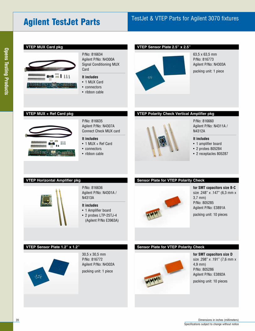
Sensor Plate for VTEP Polarity Check
for sMt capacitors size dsize .298” x .191” (7,6 mm x 4,9 mm) P/No: 805286 Agilent P/No: E3892A
packing unit: 10 pieces
Sensor Plate for VTEP Polarity Check
for sMt capacitors size B-Csize .248” x .147” (6,3 mm x 3,7 mm) P/No: 805285 Agilent P/No: E3891A
packing unit: 10 pieces
VTEP Polarity Check Vertical Amplifier pkg
P/No: 816660 Agilent P/No: N4311A / N4312A
it includes1 amplifier board• 2 probes 805284• 2 receptacles 805287•
VTEP Sensor Plate 2.5” x 2.5”
63,5 x 63,5 mm P/No: 816773 Agilent P/No: N4303A
packing unit: 1 piece
VTEP Sensor Plate 1.2” x 1.2”
30,5 x 30,5 mm P/No: 816772 Agilent P/No: N4302A
packing unit: 1 piece
VTEP Horizontal Amplifier pkg
P/No: 816636 Agilent P/No: N4301A / N4313A
it includes1 Amplifier board• 2 probes LTP-25TJ-4 •
(Agilent P/No E3963A)
VTEP MUX + Ref Card pkg
P/No: 816635 Agilent P/No: N4307A Connect Check MUX card
it includes1 MUX + Ref Card• connectors• ribbon cable•
VTEP MUX Card pkg
P/No: 816634 Agilent P/No: N4300A Signal Conditioning MUX Card
it includes1 MUX Card• connectors• ribbon cable•
Agilent testJet Parts

21Dimensions in inches (millimeters)Specifications subject to change without notice
Open
s Te
stin
g Pr
oduc
ts
OpensXpress Parts for GenRad fixtures
Sensor Plate 6.25” x .500” x .050” thick
159 x 12,7 x 1,3 mm thick P/No: 806439
packing unit: 1 piece
Sensor plate 2.56” x 2.56” x .050” thick
65 x 65 x 1,3 mm thick P/No: 806436
packing unit: 1 piece
Sensor Plate 1.25” x 1.25” x .050” thick
31,8 x 31,8 x 1,3 mm thick P/No: 806435
packing unit: 10 pieces
Sensor plate .575” x .425” x .050” thick
14,6 x 10,8 x 1,3 mm thick Size SO20 P/No: 806438
packing unit: 10 pieces
Sensor Plate .475” x .375” x .050” thick
12,0 x 9,5 x 1,3 mm thick
Size SO14, SO16 P/No: 806437
packing unit: 10 pieces
OX Sensor Connection Board pkg
(passive probe plate)
P/No: 806448
it includes1 sensor connection board• 2 hanger probes HTJ-25A•
OFM Card pkg for up to 32 sensors
P/No: 833301 GR P/No: 9004-0482-00
it includes1 OFM card• connectors• ribbon cable•
Genrad opensxpress Parts

22 Dimensions in inches (millimeters)Specifications subject to change without notice
Opens Testing ProductsSensor Plate 6.25” x .500” x .050” thick
159 x 12,7 x 1,3 mm thick P/No: 806439 Teradyne P/No: 090-362-00
packing unit: 1 piece
Sensor plate 2.56” x 2.56” x .050” thick
65 x 65 x 1,3 mm thick P/No: 806436 Teradyne P/No: 090-364-00
packing unit: 1 piece
Sensor Plate 1.25” x 1.25” x .050” thick
31,8 x 31,8 x 1,3 mm thick P/No: 806435 Teradyne P/No: 090-363-00
packing unit: 10 pieces
Sensor plate .575” x .425” x .050” thick
14,6 x 10,8 x 1,3 mm thick Size SO20 P/No: 806438 Teradyne P/No: 090-361-00
packing unit: 10 pieces
Sensor Plate .475” x .375” x .050” thick
12,0 x 9,5 x 1,3 mm thick
Size SO14, SO16 P/No: 806437 Teradyne P/No: 090-360-00
packing unit: 10 pieces
FrameScan FX 2.0 Horizontal Amp pkg
P/No: 825510 Teradyne P/No: 093-284-00
it includes1 amplifier board
2 probes like LTP-25TJ-4
ECT Hanger FrameScanPlus Amplifier pkg
P/No: 804855 Teradyne P/No: 047-531-00 Signal Conditioner + Reference Board
it includes1 amplifier board with 2 •
tapped pins SAP-25W-32 hanger probes with •
spiral spring head HTJ-25A (Teradyne P/No 047-534-00)
FrameScan FX 2.0 Fixture Kit pkg
for up to 64 sensorsP/No: 825604 Teradyne P/No: 602-946-00
it includes1 FrameScan FX 2 .0 Selector Board (MUX Card)
connenctors
ribbon cable
teradyne: Framescan Plus & Framescan Fx 2.0 Parts

23Dimensions in inches (millimeters)Specifications subject to change without notice
Open
s Te
stin
g Pr
oduc
ts
Assembled Vertical Polarity Check part
P/No of ECT Munich: SP-0075 P/No of Dover/Hungary: 805283A-D
it includes2 spring probes 805284• 1 sensor plate D 805286• soldered to amplifier board •
805283 packing unit: 1 piece
Assembled Vertical Polarity Check part
P/No of ECT Munich: SP-0074 P/No of Dover/Hungary: 805283A-BC
it includes2 spring probes 805284• 1 sensor plate B-C 805285• soldered to amplifier board •
805283packing unit: 1 piece
Sensor Plate for Polarity Check
for sMt capacitors size d
size: .298” x .191” (7,6 x 4,9 mm) P/No: 805286
packing unit: 10 pieces
Sensor Plate for Polarity Check
for sMt capacitors size B-C
size .248” x .147” (6,3 x 3,7mm) P/No: 805285
packing unit: 10 pieces
CapScan Vertical Amplifier pkg
P/No: 805283
it includes1 amplifier board• 2 probes 805284• 2 receptacles 805287•
packing unit: 1 package
teradyne: Framescan Plus & Framescan Fx 2.0 Parts


sPeciAl Products
26 Dimensions in inches (millimeters)Specifications subject to change without notice
Special Products
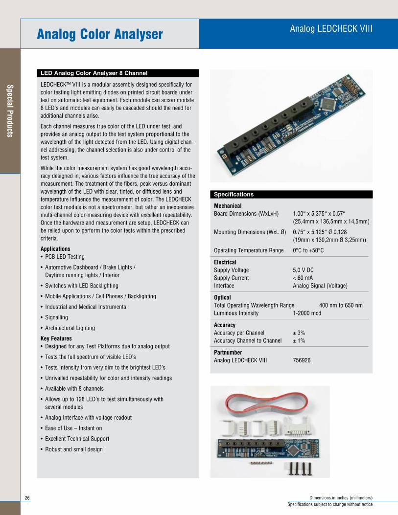
Specifications
MechanicalBoard Dimensions (WxLxH) 1 .00“ x 5 .375“ x 0 .57“ (25,4mm x 136,5mm x 14,5mm)
Mounting Dimensions (WxL Ø) 0 .75“ x 5 .125“ Ø 0 .128 (19mm x 130,2mm Ø 3,25mm)
Operating Temperature Range 0°C to +50°C
ElectricalSupply Voltage 5,0 V DC Supply Current < 60 mA Interface Analog Signal (Voltage)
opticalTotal Operating Wavelength Range 400 nm to 650 nm Luminous Intensity 1-2000 mcd
accuracyAccuracy per Channel ± 3% Accuracy Channel to Channel ± 1%
PartnumberAnalog LEDCHECK VIII 756926
LED Analog Color Analyser 8 Channel
LEDCHECK™ VIII is a modular assembly designed specifically for color testing light emitting diodes on printed circuit boards under test on automatic test equipment . Each module can accommodate 8 LED’s and modules can easily be cascaded should the need for additional channels arise .
Each channel measures true color of the LED under test, and provides an analog output to the test system proportional to the wavelength of the light detected from the LED . Using digital chan-nel addressing, the channel selection is also under control of the test system .
While the color measurement system has good wavelength accu-racy designed in, various factors influence the true accuracy of the measurement . The treatment of the fibers, peak versus dominant wavelength of the LED with clear, tinted, or diffused lens and temperature influence the measurement of color . The LEDCHECK color test module is not a spectrometer, but rather an inexpensive multi-channel color-measuring device with excellent repeatability . Once the hardware and measurement are setup, LEDCHECK can be relied upon to perform the color tests within the prescribed criteria .
applications• PCB LED Testing
• Automotive Dashboard / Brake Lights / Daytime running lights / Interior
• Switches with LED Backlighting
• Mobile Applications / Cell Phones / Backlighting
• Industrial and Medical Instruments
• Signalling
• Architectural Lighting
Key Features• Designed for any Test Platforms due to analog output
• Tests the full spectrum of visible LED’s
• Tests Intensity from very dim to the brightest LED’s
• Unrivalled repeatability for color and intensity readings
• Available with 8 channels
• Allows up to 128 LED’s to test simultaneously with several modules
• Analog Interface with voltage readout
• Ease of Use – Instant on
• Excellent Technical Support
• Robust and small design
Analog color Analyser Analog LEDCHECK VIII

27Dimensions in inches (millimeters)Specifications subject to change without notice
Spec
ial P
rodu
cts
Optical Fiber Cable
The Optical Fiber Cable includes a fastening kit to support each fiber cable to the adapter . The LEDCHECK Module end of the fiber cable is only being cut in length, making it easy to adjust and attach the fiber cable to the module . The light source end of the cable comes with different length metal tubes (tips) as listed below .
technicial detailsFiber Cable Outer Diameter: 0 .087” (2,20 mm) Fiber Cable Length: 27“ (680 mm) Metal Tube Length: 0 .75“ (19 mm) Metal Tube Length: 1 .25“ (31 mm) Metal Tube Length: 2 .00“ (50 mm)
Part numbersOptical Fiber Cable 0 .75“ long Tube: 756309 Optical Fiber Cable 1 .25“ long Tube: 756307 Optical Fiber Cable 2 .00“ long Tube: 756308
Analog color AnalyserAnalog LEDCHECK VIII Accessories

28 Dimensions in inches (millimeters)Specifications subject to change without notice
Special Products
digital color Analyser
Specifications LEDCHECK with 1mm Fiber
MechanicalBoard Dimensions (WxLxH) 70 x 65 x 35mm Optical Fiber Length 600 mm Fiber Outer diameter including cladding 1,00 mm Number of Optical Fibers 3 or 5 pieces Tightest bend radius of Fiber 15 mm Operating Temperature Range 0°C to +50°C
ElectricalSupply Voltage 5,0 V Supply Current 80 mA Interface RS232 (Serial) and USB
opticalRed Peak Efficiency Wavelength 615 nm Green Peak Efficiency Wavelength 540 nm Blue Peak Efficiency Wavelength 465 nm Total Operating Wavelength Range 450 nm to 650 nm
accuracyWhite x = ± 0,0015, y = ± 0,0015 Red (615nm) ± 3 nm Green (540nm) ± 4 nm Blue (465nm) ± 3 nm
PartnumberLEDC-3-1 Digital LEDCHECK III LEDC-5-1 Digital LEDCHECK V
Specifications LEDCHECK with 2.2mm Fiber
Same as above with the exception that the fiber optic cable diam-eter is increased to 2,2mm for improved light intensity measure-ments .
MechanicalOptical Fiber Length 600 mm Fiber Outer diameter including cladding 2,20 mm Number of Optical Fibers 3 or 5 pieces Tightest bend radius of Fiber 17,6 mm
PartnumberLEDC-3-2 Digital LEDCHECK III LEDC-5-2 Digital LEDCHECK V
Digital LEDCHECK 3 or 5 Channel
The ECT Digital Color Analyzer allows fast and automatic testing the Color and Brightness (Intensity) of Light Emitting Devices (LEDs) . Tests the full spectrum of visible LEDs from very dim to the brightest on the market .
The new digital color sensor allows unrivalled repeatability for color and intensity testing .
applications• PCB LED Testing
• Automotive Dashboard / Brake Lights, Daytime running lights / Interior
• Switches with LED Backlighting
• Mobile Applications - Cell Phones, Backlighting
• Industrial and Medical Instruments
• Signalling
• Architectural Lighting
Key Features• Designed for any Test Platforms
• Tests the full spectrum of visible LEDs
• Tests Intensity from very dim to the brightest LEDs
• Unrivalled repeatability for color and intensity readings
• Available with 3 or 5 channels
• Allows up to 495 LEDs to test simultaneously
• Ease of Use – Instant on
• Excellent Technical Support
• Free Drivers and Software
• Designed for Testing Color and White LEDs
• Tests Bicolor and Tricolor LEDs
• RS 232 and USB Interface
• Robust and reliable design
• Uses flexible plastic Optical Fibres for ease of installation
Digital LEDCHECK III & V
LEDCHECK V

29Dimensions in inches (millimeters)Specifications subject to change without notice
Spec
ial P
rodu
cts
Optical Head
The Optical Head has been designed to reduce the placement sen-sitivity of the Optical Fiber when testing LED’s .
Optical Head Outer diameter 4,55 mm Optic capture angle 12 degrees Optical Fiber Outer diameter 1,00 mm
Part numbersOptical Head OH - 1, Length: 36,75 mm
Optical Head OH - 2, Length: 27,00 mm
Optical Head OH - 3, with Fiber Clamp Length: 49,50 mm
Optical Fiber Clamp
Attachment for positioning the thin fiber with 1mm outside diam-eter
PartnumberFiber Clamp for 1,0 mm Optical Fiber CC - 1 Fiber Clamp for 2,2 mm Optical Fiber CC - 2
Optical Fiber Receptacle
75 mil receptacle with pressring 75 mil receptacle for positioning the 1mm Optical fiber
PartnumberReceptacle LTR-1W
Optical Fiber Knife
Cutting tool for the optical fiber 1,0 mm and 2,2 mm fiber can be shortened with a the fiber knife to the correct length .
In order to guarantee a clean cut of the fiber it is recommended to use each cutting hole only once .
PartnumberOptical Fiber Knife OFK - 2
Digital LEDCHECK Accessories digital color Analyser

30 Dimensions in inches (millimeters)Specifications subject to change without notice
Special Products
Board Marker Probe
The BMP-1 Board Marker Probe patented design is for installation on bare board or loaded board test fixtures . When your tester is equipped with the appropriate electronics and software, the BMP-1 scribes a permanent .050” circle on every “passed” PCB tested . Boards that fail the test are not marked . The risk of human error is eliminated in PCB testing and sorting .
The unit requires less than .500” of fixture area . It is designed to mark board areas of bare glass (FR4), solder mask over glass or copper, or bare tinned copper .
The BMP-1 includes a mounting receptacle with press ring, and a motor/transmission assembly . It can be easily removed from the receptacle for use in other fixtures . Spare receptacles and tip replacement assemblies are available . The thread between recep-tacle and housing is 7/16-20 UNF .Consult factory for information on electronic and software requirements, and replace-ment receptacles and tip assemblies .
Probe Specifications BMP-1
MechanicalFull Marker Tip Travel .062 (1 .57) Recommended Working Travel .050 (1 .27) Direction of Rotation CCW Scribed Diameter 0 .50 (1 .27)
Electrical (operating Conditions)Current Rating 50 mA Voltage Rating 15 VDC Recommended Duty Cycle 1 sec . On (min .), 5 sec . Off
Materials and FinishesPlunger Tip Carbide Receptacle Stainless steel
Mounting hole size .468/.469 (11.89/11.91)
To Order
Specify model number of components or tools you require:
BMP-1: Probe and receptacle, wires and male + female connectors included, (-red, + black) . BMr-1: Receptacle only . BMt-1: Tip replacement assembly for BMT-1 . rit-BMP: Receptacle insertion tool for BMR-1 . EXt-BMP: Receptacle extraction tool for BMR-1 .
Board Marker Probe
.050 (1.27)
Fixture Plate
.080 (2.03)
.070 (1.78)
Spacer
.025 (0.64)
Ø .050 (1.27)Scribe Circle
receptacle
1.93(49.0)
.250 (6.35)
.125 (3.18)
.472 (12.0)
Black (+) Red (-)
Warning: Adequate thickness spacers MUST be used to limit board travel as shown . Failure to use proper spacers will allow probe to bottom out, stalling the motor and permanently damaging the marker probe .

31Dimensions in inches (millimeters)Specifications subject to change without notice
Spec
ial P
rodu
cts
Personality Pins for Agilent Fixtures / indicator Probe
Personality Pins
P/No: PP-3070-S• Agilent P/No: Mint Pins 44275P• Packing unit: 200 pieces•
Indicator Probe
This probe is a special use probe to check the probe stroke of a test fixture . Barrel deformations are located in the front of the assembly to hold the plunger after activation at it´s compressed posi-tions . Subsequently the stroke of the test fixture can be measured . Thenafter, the plunger can be pulled back with tweezers to the extended position .
P/No: POGO-25IP-C• To be used in size 25 receptacles like •
SPR-25W-xPacking unit: 10 pieces•
Other dimensions 75 mil or 50 mil upon request .
Retaining Feature Ø .054 (1.37)
1.300 (33.0).330 (8.4)
Ø .036 (0.9)
PoGo-25iP-C

32
Special Products
Connectors shown without cableSpecifications subject to change without notice
Test Connectors
Test Connectors are typical used for Final or Functional Test, whereas the Test Connector is pneumatical driven into the test objects connector .
The Test Connectors are free floating or can be used with a self guiding block to pre-align the connector before engaging the test object .
All Test Connectors are designed and made with High Perfomance Plastic to assure high lifecycles of typical up to 100 .000 insertions .
ECT offers a variety other connector types, pincounts or custom cable length for:
TAE• Power DC (2 .1mm Ø)• LVDS• RTX• Various others . . .•
noteThese “Made in Germany” Connectors are sold worldwide by ECT-Munich only .
Floating Test ConnectorsHdMi connector
HDMI Connector
Model Number: HDMI Connector Connectors: 19 Pins Gold Plated Housing Material: High Performance Plastic Voltage Rating: max . 40V Wiring: none / upon request Part Number: 15 .52 .59 .00 .0

33
Spec
ial P
rodu
cts
Connectors shown without cableSpecifications subject to change without notice
Floating Test Connectors Mini Western connectors
4-Pin Mini Western Connector (900mm cable)
Model Number: 4-Pin Western Connector Connectors: 4 Pins Gold Plated Housing Material: High Performance Plastic Voltage Rating: max . 230V Wiring: 900mm Color Coded Ribbon Cable Part Number: 10 .41 .67 .00 .0
10-Pin Mini Western Connector (300mm cable)
Model Number: 10-Pin Western Connector Connectors: 10 Pins Gold Plated Housing Material: High Performance Plastic Voltage Rating: max . 230V Wiring: 300mm Color Coded Ribbon Cable Part Number: 10 .14 .57 .00 .0
8-Pin Mini Western Connector (250mm cable)
Model Number: 8-Pin Western Connector Connectors: 8 Pins Gold Plated Housing Material: High Performance Plastic Voltage Rating: max . 230V Wiring: 250mm Color Coded Ribbon Cable Part Number: 10 .41 .70 .00 .0
8-Pin Mini Western Connector (900mm cable)
Model Number: 8-Pin Western Connector Connectors: 8 Pins Gold Plated Housing Material: High Performance Plastic Voltage Rating: max . 230V Wiring: 900mm Color Coded Ribbon Cable Part Number: 10 .41 .69 .00 .0
6-Pin Mini Western Connector (900mm cable)
Model Number: 6-Pin Western Connector Connectors: 6 Pins Gold Plated Housing Material: High Performance Plastic Voltage Rating: max . 230V Wiring: 900mm Color Coded Ribbon Cable Part Number: 10 .41 .68 .00 .0

34
Special Products
Connectors shown without cableSpecifications subject to change without notice
usB connectors Floating Test Connectors
5-Pin USB Micro Connector
Model Number: 5-Pin USB Micro Connector Connectors: 5 Pins Gold Plated Housing Material: High Performance Plastic Voltage Rating: max . 40V Wiring: none / upon request Part Number: 10 .14 .57 .00 .0
5-Pin USB Mini Connector
Model Number: 5-Pin USB Mini Connector Connectors: 5 Pins Gold Plated Housing Material: High Performance Plastic Voltage Rating: max . 40V Wiring: none / upon request Part Number: 10 .14 .66 .00 .0
5-Pin USB Mini Connector with Guiding Feature
Model Number: 5-Pin USB Mini Connector Guiding Connectors: 5 Pins Gold Plated Housing Material: High Performance Plastic Voltage Rating: max . 40V Wiring: none / upon request Part Number: 10 .14 .67 .00 .0
4-Pin USB Connector Type B
Model Number: 4-Pin USB Connector Type B Connectors: 4 Pins Gold Plated Housing Material: High Performance Plastic Voltage Rating: max . 40V Wiring: none / upon request Part Number: 10 .14 .46 .00 .0
4-Pin USB Connector Type A
Model Number: 4-Pin USB Connector Type A Connectors: 4 Pins Gold Plated Housing Material: High Performance Plastic Electrical Rating: max . 40V / max . 2 .5A Wiring: none / upon request Part Number: 10 .14 .40 .00 .0

35
European sales officeEVERETT CHARLES TECHNOLOGIES Muenchener Straße 19 D-85540 Haar Germany E-mail: ectmuc@ectinfo .com
GermanyECT-Munich E-mail: ectmuc@ectinfo .com
HATEC E-mail: info@hatec .net
Leitec Test Solutions GmbH E-mail: info@leitec .info
turkeyEsman Elektronik Inc . E-mail: esman@esmanelektronik .com
Estonia / FinlandMETRIC INDUSTRIAL OY
PortugalITEC E-mail: itec@itec .pt
SILGAL, LDA . E-mail: info@silgal .com
spainATIS sdad .anma . E-mail: electronica@atissa .com
south africaTest Fixture Technologies E-mail: info@testfixtures .co .za
Microsource CC
tunesiaAdelec
euroPe & afrICa
EVERETT CHARLESTECHNOLOGIES
Contact Products Group
Fixture & services Group
Capital Equipment Group
Multitest Group harbor Electronics

Edition ECM / 10/2010
Production portfolio of ECt und affiliates
spring loaded probes
Fixtures for iCt- & Functional tests
test interface boards
Contactors for semiconductor integrated circuits
test handlers
Bareboard test equipment
World headquarters
Everett Charles Technologies 700 East Harrison Avenue Pomona, CA 91767, USA Phone: +1 909-625-5551 Fax: +1 909-624-9746 Web: www .ectinfo .com
European sales office
Everett Charles Technologies Muenchener Str . 19 D-85540 Haar Phone: +49 (0) 89-429204 Fax: +49 (0) 89-428282 E-mail: ectmuc@ectinfo .com Internet: www .ectinfo .de
EVERETT CHARLESTECHNOLOGIES