FIVE - Penn State College of Engineering JOMS 5.doc · Web viewThis paper presents a description of...
28
Rapid planning for CNC machining – a new approach for Rapid Prototyping Matthew Frank, Department of Industrial and Manufacturing Systems Engineering Iowa State University, Ames, IA 50011 Richard A. Wysk and Sanjay B. Joshi, Department of Industrial and Manufacturing Engineering, Penn State University, University Park, PA 16802 Abstract This paper presents a description of how CNC milling can be used to rapidly machine a variety of parts with minimal human intervention in process planning. The methodology presented uses a layered–based approach for machining (like traditional rapid prototyping) for the rapid, semi-automatic machining of common manufactured part geometries on a variety of materials. Parts are machined using a plurality of 2½-D toolpaths from orientations about a rotary axis. Process parameters such as the number of orientations, tool containment boundaries and tool geometry are derived from CAD slice data. In addition, automated fixturing is accomplished through the use of sacrificial support structures added to the CAD geometry. The paper begins by describing the machining methodology, and then presents a number of critical issues needed to make the process automatic and efficient. Example parts machined using this methodology are then presented and discussed. Keywords: CNC machining, rapid manufacturing, rapid prototyping, process planning, computer aided manufacturing. Introduction The cost of producing small numbers of parts has been driven by the cost required to process engineer the part(s). Traditional Computer Aided Process Planning (CAPP) systems have reduced the time required to plan machined parts, but the cost for one or two of a kind machined parts is still dominated by the cost of planning the part. The current use of CNC machining for these small quantities of parts is further limited by
-
Upload
vuongtuong -
Category
Documents
-
view
214 -
download
1
Transcript of FIVE - Penn State College of Engineering JOMS 5.doc · Web viewThis paper presents a description of...

Rapid planning for CNC machining – a new approach for Rapid Prototyping
Matthew Frank, Department of Industrial and Manufacturing Systems EngineeringIowa State University, Ames, IA 50011
Richard A. Wysk and Sanjay B. Joshi, Department of Industrial and Manufacturing Engineering, Penn State University, University Park, PA 16802
AbstractThis paper presents a description of
how CNC milling can be used to rapidly machine a variety of parts with minimal human intervention in process planning. The methodology presented uses a layered–based approach for machining (like traditional rapid prototyping) for the rapid, semi-automatic machining of common manufactured part geometries on a variety of materials. Parts are machined using a plurality of 2½-D toolpaths from orientations about a rotary axis. Process parameters such as the number of orientations, tool containment boundaries and tool geometry are derived from CAD slice data. In addition, automated fixturing is accomplished through the use of sacrificial support structures added to the CAD geometry. The paper begins by describing the machining methodology, and then presents a number of critical issues needed to make the process automatic and efficient. Example parts machined using this methodology are then presented and discussed.
Keywords: CNC machining, rapid manufacturing, rapid prototyping, process planning, computer aided manufacturing.
IntroductionThe cost of producing small numbers
of parts has been driven by the cost required to process engineer the part(s). Traditional Computer Aided Process Planning (CAPP) systems have reduced the time required to plan machined parts, but the cost for one or
two of a kind machined parts is still dominated by the cost of planning the part. The current use of CNC machining for these small quantities of parts is further limited by special tooling costs and machine set up.
The typical approach to planning parts for CNC machining has been to define the “features” on the part, and match these features and tolerances to a set of processes that can create the required geometry to the specified accuracy. This approach has worked reasonably well for medium to high volume parts, but it has had limited success for the production of very small quantities of parts. In most cases, the time required to plan the part, kit the required tooling, and set-up the machine (both fixture and tooling) has limited the use of CNC for these applications. The result is that rapid deployment of CNC machining has been relegated to a simple set of part geometries. We believe that it is the promise of minimal process engineering that has driven the use of free form rapid prototyping (RP) techniques. Unfortunately, many of these processes have been restricted to a small set of materials with limited geometric accuracy.
In the literature, process planning is often approached with a set of goals driven by high production levels of parts. That is, a set of plans that strive for cost-effectiveness through maximizing feeds and speeds and creating repeatable setups that can be paid for through economies of scale. Process

planning for CNC machining includes tasks such as fixture planning, toolpath planning, and tool selection. There is a considerable amount of work in the literature pertaining to these three areas (Marapoulos, 1995; Chen et al., 1998; Joneja and Chang, 1999). The concept of flexible fixturing has been the topic of much research, though a completely autonomous fixture design system has yet to be developed (Bi and Zhang, 2001).
Some exploration into the use of CNC machines for rapid prototyping has been published. Chen and Song describe layer-based robot machining for rapid prototyping using machined layers that are laminated during the process (Chen and Song, 2001). The process is demonstrated using laminated slabs of plastic, machined as individual layers upon gluing to the previous layers.
A hybrid approach using both deposition and machining called Shape Deposition Manufacturing (SDM) continues to be developed (Merz et al., 1994). For each layer, both support and build material is deposited and machined in a combined additive and subtractive process. Sarma et al. (1997) presented Reference Free Part Encapsulation (RFPE) as a new approach to using phase-change fixturing for machining (Sarma and Wright, 1997). The approach is discussed recently in conjunction with high speed machining (HisRP) (Shin et al., 2002). RFPE, in combination with feature based CAD/CAM was proposed as an RP system (Choi et al., 2001).
Another approach is to use CNC machining for prototyping dies, an area called Rapid Tooling (Radstok, 1999). One approach to rapid tooling uses machined metal laminates stacked to form dies (Vouzelaud et al., 1992; Walczyk and Hardt, 1998).
Many of these methods utilize CNC machining, but do not address the
fundamental problems of automating a fully subtractive rapid machining approach. In this paper, we present a method for “feature-free” CNC machining that requires little or no human-provided process engineering. The methodology described in this paper is a purely subtractive process that can be applied to any material that can be machined. The method described herein was developed in response to the challenge of automating as much of the process engineering as possible. The ultimate goal is to generate both the NC code and an automatically executed fixturing system by the touch of a button, using only a CAD model and material data as input. We feel that the process is perfectly suited for prototypes as well as parts that will be produced in small quantities (~1-10).
Before beginning a discussion on the methodology, it is necessary to elucidate our set of constraints, both known problems in CNC machining and some self-imposed by the authors. We begin with a general assumption about the user; in particular, that the human planner has no experience in machining. We justify this in light of the fact that one use of this methodology is for prototyping. During the early stages of design, one cannot assume that a machinist is available. The system may need to be usable by a designer or engineer inexperienced in machining. The existing RP processes allow users to download CAD files and simply push a button to initiate the part building process. The same will need to be true for a rapid machining process. What does this mean in terms of the typical steps for process planning? The implication is that even moderately skilled tasks including setting fixture and tool offsets must be eliminated. Even more importantly, fixture design and implementation must be at least semi-automated. Overall, we only expect that the user will be responsible for loading a piece of stock in a work holding device
that is straightforward to use (e.g.: simple vice, chuck, collet, etc.).
Another assumption is that we will not have feature information as data input. In some cases of simple prismatic parts, feature extraction may not be a problem, but for the general free form part shape, we cannot assume that accurate and complete feature information is known. An example would be a CAD model generated by laser scanning of biological objects, like bones. This assumption suggests that toolpath plans must be generated without knowing what type of surface geometry are to be machined. This includes choosing the tool diameter and length, depth of cut, feeds and speeds. Specifically, this assumption implies that our process planning method is not intended for populating features on a piece of stock material, rather, the entire surface of the CAD model must be cut from the stock material. Although the difference may appear subtle, this assumption will be shown to have a significant impact on the framework of this methodology. Lastly, we will assume that this process will be executed in a lights-out operation. Given that, we must prevent any catastrophic failure such as crashing the tool, holder, or spindle with any part of the machine tool or fixture.
Overview of the MethodologyThis section presents a general
overview of the current methodology. Methods have been developed to cover all aspects of process planning for rapid machining, including toolpath planning, choosing tool geometries, calculating setup orientations, and a concept for a universal approach to fixturing.
With regard to toolpath planning, the method borrows from the layer-based RP methods. The general idea is to machine the visible surfaces of the part from each of a plurality of orientations. From each
orientation, some, but not all of the part surfaces will be visible. Only parts whose entire external surface is visible can be completed machined with this methodology. In some ways this limits what can be done when comparing the methodology described herein to traditional RP techniques, but in no way reduces the flexibility when compared to traditional CNC machining. The goal is to machine the part from enough orientations, such that, after all toolpaths are complete, all surfaces have been fully machined from at least one orientation. For each orientation, we do not plan a set of feature machining operations; rather, each orientation is machined using simple 2½-D layer-based toolpaths. This is very similar to the existing rapid prototyping systems, although we are limited to removing only visible layers from each orientation instead of creating and stacking all of the true cross sections of the part from just one orientation.
Unlike the existing rapid prototyping methods, CNC machining is a subtractive process; therefore, one can only remove the material around the periphery of a part (visible cross section of the part). In order to simplify the problem from both a process and fixture-planning standpoint, we use rotations about one axis for orientations of the stock material during processing. This not only reduces the problems associated with process planning, but we will show that this supports the collision-free nature of the approach.
The method can be executed on a 3-axis CNC milling machine with a 4th axis indexer. Round stock material is fixed between two opposing chucks and rotated between operations using the indexer. For each orientation, all visible surfaces are machined using simple layer-based toolpath planning. The feature-free nature of this method suggests that it is unnecessary to have any surface be completely machined in any particular orientation. The goal is to
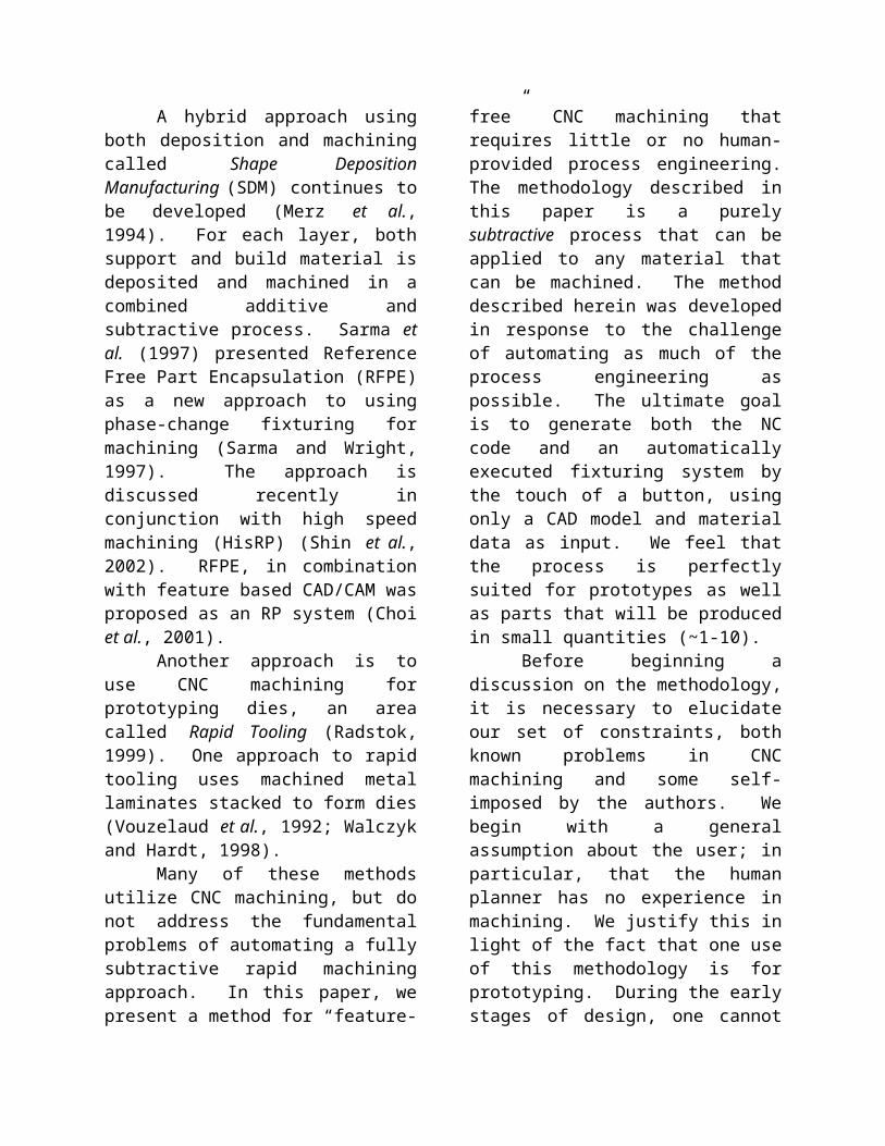
simply machine ALL surfaces after ALL orientations have been completed. This process is illustrated in Figure 1.
In the first operation (Figure 1a.) much of this surface is visible from the first orientation; however, the dark areas under the overhanging surface are not visible. In the second operation, this originally “shadowed” region of the same surface is now visible (Figure 1b). This approach avoids the problem of feature recognition and feature-based process planning. At least two, but more likely numerous orientations will be required in order to machine all the surfaces of a part about one axis of rotation. Even a simple part like a sphere will require two orientations.
Since we assume that no feature information is available, then a general method for tool selection is required. At each orientation, a tool is required that can reach to the last layer for machining without colliding with any previously machined surface or the stock material. This requires that the shank diameter be less than or equal to the flute diameter. Since we are using
simple 2½-D toolpaths, then a flat end tool is an appropriate choice. One will note that this is similar to roughing operations in traditional machining process planning, only in this case, we set our layer depth shallow enough (typically, maximum of 0.005”) that we expect near finish machining results. Lastly, the diameter of the tool is simply the smallest diameter available in the given length. Since we assume that no feature information is available, then the only general approach is to use a small diameter tool such that the most general shapes can be accessed.
By this method part surface contours are created with the same “staircase” effect seen in other RP methods. However, since machining is able to make very shallow depths of cut, rapid machining can produce very thin layer thicknesses. Although machining time increases with reduction in layer thickness, it does not necessarily do so proportionally, since shallower depths of cut enable higher feed rates. Rapid machining can achieve layer thicknesses easily down to 0.003” or less.
One would note that if we were to machine all the visible surfaces of a part from numerous orientations about an axis of rotation, then at some point the part would simply fall from the stock material. However, this method employs a fixturing approach that is similar in concept to the “sacrificial supports” used in many existing rapid prototyping processes. In this case, the supports are not added to the physical model, rather, they must be generated as added surfaces prior to toolpath planning. The sacrificial supports are currently implemented as small diameter cylinders added to the solid model geometry parallel to the axis of rotation. During processing, the supports are created incrementally, along with the rest of the part surfaces. Upon completion, the finished part is left secured
Figure 1 – Free-form surface machined with multiple layer-based toolpaths
(a)
(b)

Round stock, fixed between chucks
Small diameter flat-end mill tool
4th-axis indexer
Tailstock
CNC-RP Method: A model is machined on a 3-Axis mill with an indexer and tailstock using layer-based toolpaths from numerous orientations about an axis of rotation.
PROCESSING STEPS
(Side View) Machine the visible surfaces from each of a set of orientations using layer-based toolpaths
ROTATE to next orientation
MACHINE
ROTATE
MACHINE
ROTATE
MACHINE
REMOVE model at sacrificial supports
The number of rotations
required to machine a model is dependent on
its geometric complexity
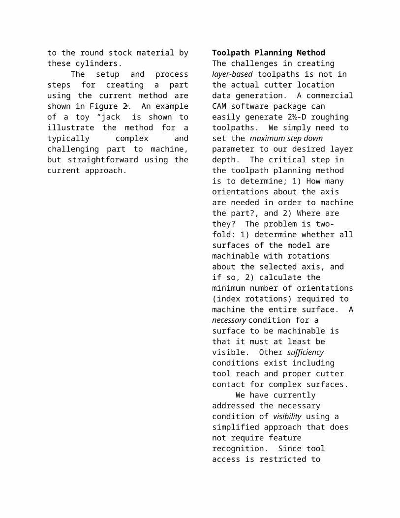
Figure 2 – Process steps for CNC-RP
Methodology :
to the round stock material by these cylinders.
The setup and process steps for creating a part using the current method are shown in Figure 2. An example of a toy “jack” is shown to illustrate the method for a typically complex and challenging part to machine, but straightforward using the current approach.
Toolpath Planning MethodThe challenges in creating layer-based toolpaths is not in the actual cutter location data generation. A commercial CAM software package can easily generate 2½-D roughing toolpaths. We simply need to set the maximum step down parameter to our desired layer depth. The critical step in the toolpath planning method is to determine; 1) How many orientations about the axis are needed in order to machine the part?, and 2) Where are they? The problem is two-fold: 1) determine whether all surfaces of the model are machinable with rotations about the selected axis, and if so, 2) calculate the minimum number of orientations (index rotations) required to machine the entire surface. A necessary condition for a surface to be machinable is that it must at least be visible. Other sufficiency conditions exist including tool reach and proper cutter contact for complex surfaces.
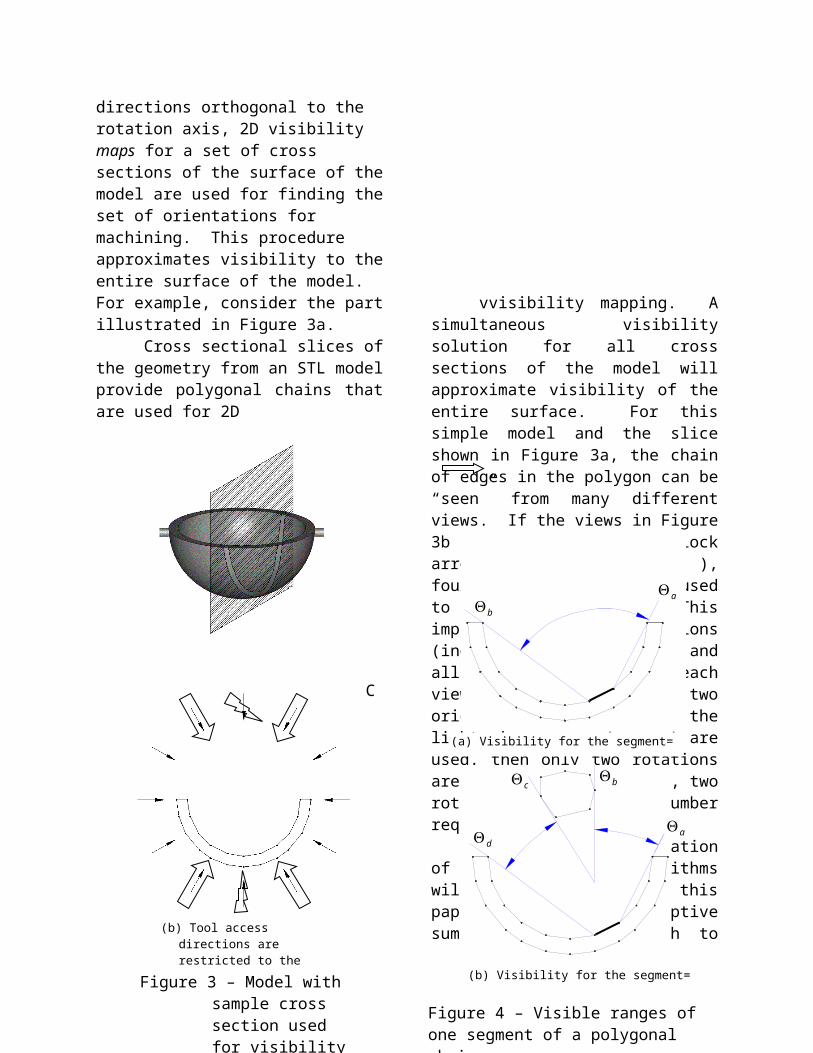
We have currently addressed the necessary condition of visibility using a simplified approach that does not require feature recognition. Since tool access is restricted to directions orthogonal to the rotation axis, 2D visibility maps for a set of cross sections of the surface of the model are used for finding the set of orientations for machining. This procedure approximates visibility to the entire surface of the model. For example, consider the part illustrated in Figure 3a.
Cross sectional slices of the geometry from an STL model provide polygonal chains that are used for 2D
(b) Tool access directions are restricted to the slice plane
Figure 3 – Model with sample cross section used for visibility mapping
C
vvisibility mapping. A simultaneous visibility solution for all cross sections of the model will approximate visibility of the entire surface. For this simple model and the slice shown in Figure 3a, the chain of edges in the polygon can be “seen” from many different views. If the views in Figure 3b illustrated by the block arrows are chosen ( ), four rotations could be used to machine the part. This implies that four orientations (index rotations) are used and all visible material from each view is removed. If the two orientations noted by the lightening arrows ( ) are used, then only two rotations are needed. In this case, two rotations is the fewest number required.
The entire presentation of the visibility algorithms will not be covered in this paper; however, a descriptive summary of the approach to visibility is provided in this section. For the method developed in this research, visibility for each polygonal
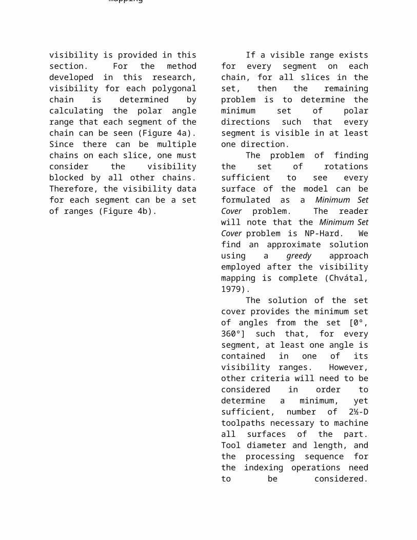
chain is determined by calculating the polar angle range that each segment of the chain can be seen (Figure 4a). Since there can be multiple chains on each slice, one must consider the visibility blocked by all other chains. Therefore, the visibility data for each segment can be a set of ranges (Figure 4b).
If a visible range exists for every segment on each chain, for all slices in the set, then the remaining problem is to determine the minimum set of polar directions such that every segment is visible in at least one direction.
The problem of finding the set of rotations sufficient to see every surface of the model can be formulated as a Minimum Set Cover problem. The reader will note that the Minimum Set Cover problem is NP-Hard. We find an approximate solution using a greedy approach employed after the visibility mapping is complete (Chvátal, 1979).
Figure 4 – Visible ranges of one segment of a polygonal chain
(a) Visibility for the segment=
ab
(b) Visibility for the segment=
a
bc
d

The solution of the set cover provides the minimum set of angles from the set [0º, 360º] such that, for every segment, at least one angle is contained in one of its visibility ranges. However, other criteria will need to be considered in order to determine a minimum, yet sufficient, number of 2½-D toolpaths necessary to machine all surfaces of the part. Tool diameter and length, and the processing sequence for the indexing operations need to be considered. Furthermore, one needs to determine the axis or axes of rotations necessary to machine all the surfaces.
In our approach, it is only important that all surfaces of the part geometry are visible in some direction. Since this methodology uses segments of polygons, this implies that each segment must be visible from some polar direction, regardless of any other segments around the one being investigated.
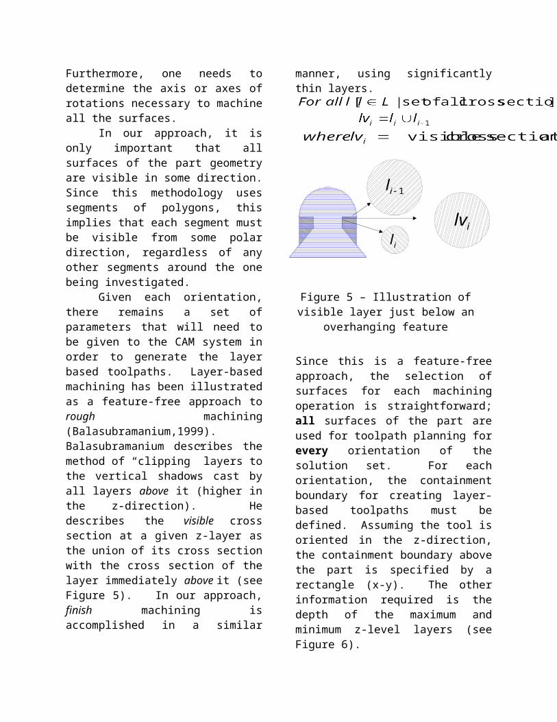
Given each orientation, there remains a set of parameters that will need to be given to the CAM system in order to generate the layer based toolpaths. Layer-based machining has been illustrated as a feature-free approach to rough machining (Balasubramanium,1999). Balasubramanium describes the method of “clipping” layers to the vertical shadows cast by all layers above it (higher in the z-direction). He describes the visible cross section at a given z-layer as the union of its cross section with the cross section of the layer immediately above it (see Figure 5). In our approach, finish machining is accomplished in a similar manner, using significantly thin layers.
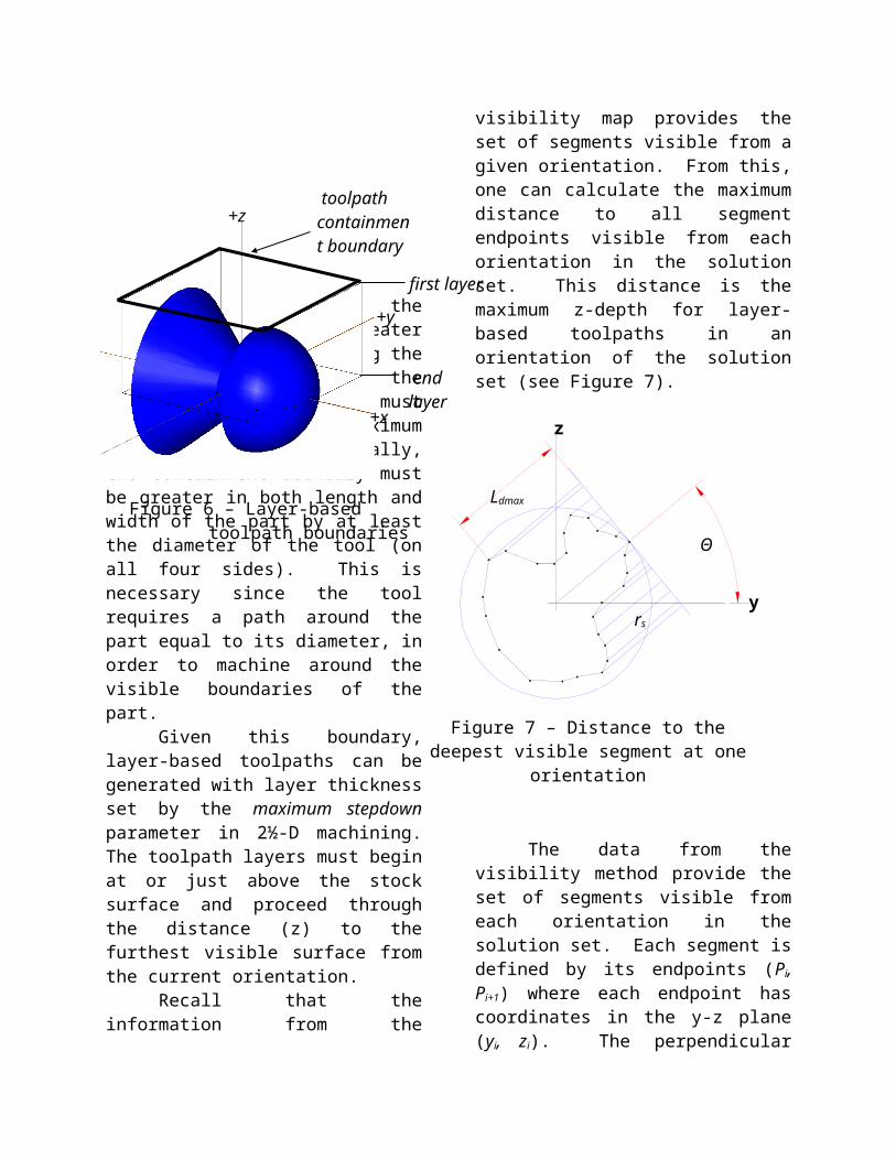
Since this is a feature-free approach, the selection of surfaces for each machining operation is straightforward; all surfaces of the part are used for toolpath planning for every orientation of the solution set. For each orientation, the containment boundary for creating layer-based toolpaths must be defined. Assuming the tool is oriented in the z-direction, the containment boundary above the part is specified by a rectangle (x-y). The other information required is the depth of the maximum and minimum z-level layers (see Figure 6).
The length of the boundary (x) must be greater than the part length along the axis of rotation, while the width of the boundary (y) must be greater than the maximum part diameter. Specifically, the containment boundary must be greater in both length and width of the part by at least the diameter of the tool (on all four sides). This is necessary since the tool requires a path around the part equal to its diameter, in order to machine around the visible boundaries of the part.
Given this boundary, layer-based toolpaths can be generated with layer thickness set by the maximum stepdown parameter in 2½-D machining. The toolpath layers must begin at or just above the stock surface and proceed through the distance (z)
1il
ililv
Figure 5 – Illustration of visible layer just below an overhanging feature
+x
+y
+z
first layer
end layer
toolpath containment boundary
Figure 6 – Layer-based toolpath boundaries

to the furthest visible surface from the current orientation.
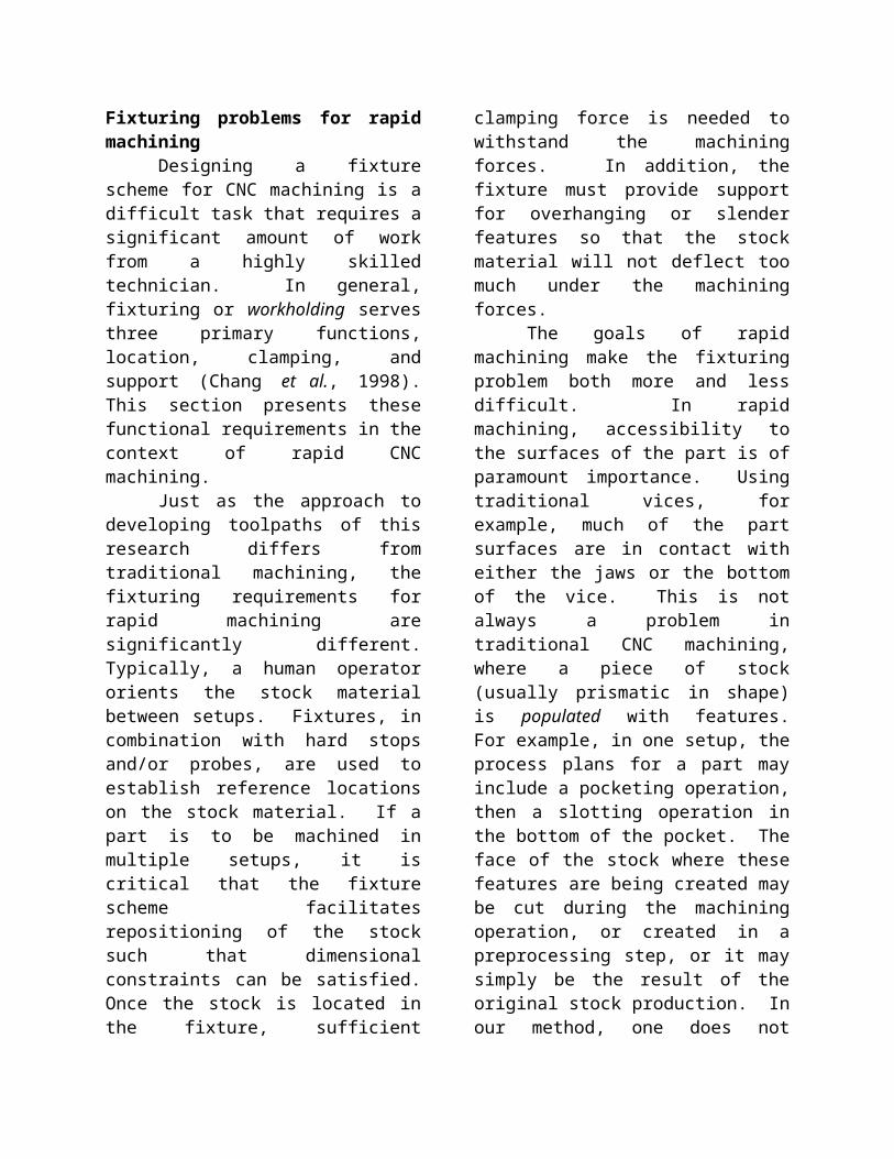
Recall that the information from the visibility map provides the set of segments visible from a given orientation. From this, one can calculate the maximum distance to all segment endpoints visible from each orientation in the solution set. This distance is the maximum z-depth for layer-based toolpaths in an orientation of the solution set (see Figure 7).
The data from the visibility method provide the set of segments visible from each orientation in the solution set. Each segment is defined by its endpoints (Pi, Pi+1) where each endpoint has coordinates in the y-z plane (yi, zi). The perpendicular distance from each point to the tangent line at the solution orientation is calculated. The maximum distance to all points visible from each orientation is used as the location of the maximum layer depth for that orientation.
Although the STL representation is used for visibility mapping, if a solid model exists, then it can be used for toolpath planning in CAM. The model is simply rotated in the CAM environment to each of the orientations from the visibility
algorithm, the toolpaths are created using the other setup parameters from the slice file information.
Tool selectionProper tool selection must ensure
collision free machining for any model complexity. One condition to ensure collision free toolpaths is that the tool length must be greater than or equal to the distance to the furthest visible surface with respect to current orientation. In this manner, one is assured that even on the deepest layer, the tool holder will not collide with the stock (see Figure 8).
To ensure that no portion of the tool will collide with any previously machined layers, the tool shank diameter must be less than or equal to the flute diameter. This criterion unfortunately makes a tool more susceptible to deflection and breakage. Typically, long tools are designed with large shank diameters and only have the length of the cutting surface (flutes) at the prescribed diameter. Figure 9 illustrates a tool with the proposed characteristics reaching to a z-depth without tool collision.
rs
Ldmax
Θ
y
z
Figure 7 – Distance to the deepest visible segment at one orientation
shank
flute
Figure 9 – Tool diameter requirement
TL
Figure 8 – Tool length requirement
A desired goal is to choose tools that will be capable of machining a variety of complex surfaces at the required accuracy. The current approach is to select the smallest tool diameter available in the necessary length that is specified. Since only 2½-D layers are to be machined, a flat-end tool is most appropriate. Whereas a ball-end (spherical) tool is able to machine smaller radii surfaces in some cases, the diminishing diameter of the cutter contact patch is a problem since very shallow depths of cut are used (see Figure 10).
As noted, one of the goals in tool selection for rapid CNC is to minimize the cutter diameter. This is directly opposite of the goals of a typical manufacturing process
plan. However, based on the assumption that feature information is not known, one must use the smallest diameter tool available in a given length. From a purely geometric standpoint, this increases the likelihood that the smallest features of the part can be machined. Tool selection is both related to, and impacts, other process planning parameters. For example, the diameter of the tool defines the extent of the toolpaths along the rotation axis direction. This affects the length of the sacrificial support cylinders since they need to protrude from the ends of the part.
Fixturing problems for rapid machiningDesigning a fixture scheme for CNC
machining is a difficult task that requires a significant amount of work from a highly skilled technician. In general, fixturing or workholding serves three primary functions, location, clamping, and support (Chang et al., 1998). This section presents these functional requirements in the context of rapid CNC machining.
Just as the approach to developing toolpaths of this research differs from traditional machining, the fixturing requirements for rapid machining are significantly different. Typically, a human operator orients the stock material between setups. Fixtures, in combination with hard stops and/or probes, are used to establish reference locations on the stock material. If a part is to be machined in multiple setups, it is critical that the fixture scheme facilitates repositioning of the stock such that dimensional constraints can be satisfied. Once the stock is located in the fixture, sufficient clamping force is needed to withstand the machining forces. In addition, the fixture must provide support for overhanging or slender features so that the stock material will not deflect too much under the machining forces.
0.005”
¼” End Mills (Flat/Ball)
Figure 10 – Cutter contact point for flat- and ball-end mill
Φ = 0.07”Φ = 0.25”
The goals of rapid machining make the fixturing problem both more and less difficult. In rapid machining, accessibility to the surfaces of the part is of paramount importance. Using traditional vices, for example, much of the part surfaces are in contact with either the jaws or the bottom of the vice. This is not always a problem in traditional CNC machining, where a piece of stock (usually prismatic in shape) is populated with features. For example, in one setup, the process plans for a part may include a pocketing operation, then a slotting operation in the bottom of the pocket. The face of the stock where these features are being created may be cut during the machining operation, or created in a preprocessing step, or it may simply be the result of the original stock production. In our method, one does not assume that any shaping operations have occurred nor is the original stock shape considered viable for a finished feature. Our methodology suggests a feature-free manufacturing approach whereby all surfaces of the part are candidate “features” to be machined from an orientation. Consider a comparison between a typical machining approach and the current methodology, as illustrated with a simple part in Figure 11. In Figure 11b, the pocket and slot are machined on the face of a block, with the sides of the block clamped by the jaws of a vice. Since these are the only two features to be machined in this setup, then the vice fixture is appropriate. This is the case where the stock material is being populated with two features, namely the pocket and slot. In Figure 11c, the same part is being machined out of a larger piece of stock material. In this case, the top, front, back and sides of the block must be machined (to some depth) in addition to the pocket and slot on the top.
Figure 11 – Comparison of traditional vs. feature-free fixturing
TopBack
Side
Front
SlotPocket
(a) Geometry of the part
tool
(c) Feature-free fixturing
(b) Traditional fixture
Vice jaws
tool
Recall, that for each setup orientation, all surfaces are used in process planning. The intent is that all visible surfaces from any orientation may be machined in that orientation. The feature-free nature of this method demands that the fixture solution provide as much access to the part as possible.
Each rotation places the stock material in a new setup orientation; however, the work offset must be retained for each orientation without having the user re-establish it. Therefore, the fixture solution for rapid machining must allow rotations of the part without the need to relocate reference points. Our fixturing method takes advantage of the fact that reorientation of the stock is only executed about one axis, which makes it easier to develop an automated method.
Typical cutting forces during machining can cause the stock material to slide or shift and some elements of the part can deflect under load. A characteristic of the method of rapid machining is that cutting forces are significantly lower in magnitude and less variable since the depth of cut is very shallow and is the same for all operations. This results in a significant decrease in the amount of clamping and support that the fixture needs to provide. Although cutting depths in traditional machining varies, if one considers the fact that a constant 0.005” or less depth of cut is used in our method, the cutting forces will be orders of magnitude less than those of a typical machining process plan.
A significant challenge for developing a fixturing scheme for rapid machining is that the fixtures must be generated automatically. Existing rapid prototyping techniques are usable by unskilled people in a turnkey application. One cannot assume that a user will be available to design and create a custom fixture for each part, nor will he/she be available to rotate/flip the stock between each new setup orientation.
Fixturing approachThe approach to fixturing for CNC
RP borrows from the general idea of sacrificial supports, which are used in existing RP systems. In this work the general intention is retained; however, the requirements for the support structures are different. The goal is to have a fixture solution that is created in-process and is customized for each part. Specific to this work, the fixture supports need to allow the part to be rotated about the axis while providing access to as much of the part surface as possible. Conventional fixturing methods for CNC often utilize vices, clamps, vacuum surfaces, etc. These approaches occlude visibility to a significant amount of the part or make it difficult to reorient the part for multiple setups. The next section describes an approach to fixturing using sacrificial supports in CNC machining.
In our method, the sacrificial supports are added to the ends of the model (in CAD) such that the model remains attached to the round stock material throughout the set of machining operations. In the current implementation of the method, small diameter cylinders are added to the model at its ends prior to creating the process plans, so that toolpaths are created to machine the cylinders in the same layer-based fashion that the model is processed.
At least one sacrificial support is necessary, but numerous ones may be required to fixture the part during machining operations. This concept is illustrated in Figure 12 where a finished part is fixed within a cylindrical piece of stock material, which in turn is fixed between the jaws of two opposing chucks. For every orientation about the axis, the relative tool (z=0) offset location is constant at the center of rotation. Similarly, the part coordinates remain at a consistent location with respect to the stock material clamped in the vice and located on the table for every rotated orientation.
A practical advantage of using sacrificial support fixturing is that, for a given setup orientation, the amount of visible surfaces can be increased compared to traditional fixtures. If a traditional vice were used and features needed to be machined on numerous surfaces, the part will need to be unclamped, reoriented and then re-clamped for each orientation. It is difficult to reorient and re-clamp a part without introducing error during location. Utilizing sacrificial supports, the stock is reoriented without changing the relative location of the part with respect to the machine table.
When the complete set of rotated toolpaths has been executed, the cylinders are cut by the user, which releases the part from the round stock material. This of
course adds a post-processing step, where the surfaces of the model at the contact point of the cylinders must be sanded, ground, etc. A proposed improvement is to generate a separate set of machining operations that focus on reducing the diameters of the cylinders for easy removal.
Using a sacrificial support, a minimal amount of the surface (the support contact “patch”) will be left inaccessible. Another drawback is the rigidity of sacrificial supports, depending on the size and number of supports used. There is a tradeoff between minimizing the size of the support for accessibility while maximizing the overall rigidity of the fixture.
In addition to the technical advantages of using sacrificial supports, there are practical advantages with respect to making this rapid machining method straightforward to implement. To setup the workpiece for our method the user clamps a piece of round stock between two chucks. The diameter of the stock is simply as large as the diameter of the part about the rotation axis, and its length can be calculated in a straightforward manner (see Figure 13).
Stock length: c = Lp + 2a + 2b
coord.(machine)
coord.(vice)coord.(part)offset(tool)
Figure 12 – Illustration of fixture setup
Dh
ba
c
Figure 13 – Setup for rapid machining
where: Lp = Part lengtha = Clamping length
b = Collision offset (x) = .5Dh
+.5Dtmax (Dh=diameter of tool holder,
Dtmax=diameter of largest tool)
The collision offset (b) ensures that a part program can be run with no risk of collision between the tool holder and either of the chucks. It is assumed that the rest of the spindle will not collide, given a proper choice of tool holder length. A significant advantage of this fixturing methodology is that work and tool offsets do not need to be set before running a part program. The collision offset (b) can be used to translate the part coordinates such that tool collision cannot occur, given a tool holder, and maximum tool diameter. This makes setting the work offsets for each new part unnecessary. The work offset coordinates [x(0), y(0)] will always be aligned with the axis and located at the face of the stationary (along x-axis) chuck on the indexer. Similarly, the tool offset is set to the z-height corresponding to the axis of rotation, as mentioned previously. If a proper length and diameter stock is clamped between the chucks, a part program can be executed collision-free with no need for the user to set offsets; a time consuming and often error-prone task in CNC machining.
Example parts made using the rapid machining methods
The visibility algorithms were implemented in C and tested on a Pentium IV, 2.0Ghz PC, running Windows XP. The software accepts slice files as input and returns several critical process parameters; 1) The minimum number of orientations, 2) The minimum stock diameter, and 3) The distance to the minimum and maximum layer depth for each orientation.
Using the set of orientations, max/min depths of cut, and stock diameter, toolpath plans can be generated using CAM software. Several metal prototypes have been machined in the laboratory. Although the intent is to integrate the visibility software with CAM and automate process planning tasks, at present the steps of toolpath processing are done manually. The steps that were executed are as follows:1. Visibility software is executed.2. The CAD model, oriented about the
intended axis, is rotated through each of the orientations of the visibility solution.
3. The toolpath containment boundary is created, using the stock and tool diameter, and the length of the part.
4. For each orientation, rough surface pocket toolpaths (MasterCAM) are generated, with min. depth at the stock radius and max. depth set to the parameters given from the visibility software.
5. NC code for each orientation is combined manually into a file with 4th axis rotation commands.
Time required for step 1 is on the order of seconds, and less than ½ minute for most parts. Steps 2-5 require 5-15 minutes depending on the number of rotations and processor speed of the computer. The following are example prototypes machined in the laboratory.
The first prototype is the toy Jack. The Jack was machined on a Haas VF-0 3-axis machining center. The number of orientations provided by the visibility method was five. An indexer was used to rotate the part about an axis parallel to the machine x-axis. A tailstock with a dead center was used to provide rigidity. (A tailstock with a 3-jaw chuck, was not available at the time of testing.) The material used was 6061 Aluminum in the form of 1.375” bar stock. Layer thickness was set at 0.005” while the spindle speed

and feed rate were set to 7500rpm and 350ipm, respectively (limits of the machine). A 1/8” flat-end mill at 1.5” length was used.
The part was created in approximately 3 hours. Sacrificial supports were added to the ends of the model (0.1” diameter by 0.13” long cylinders). Figure 14 shows the prototype of the Jack in between machining operations. In Figure 15, the Jack is shown after being cut from the stock at the sacrificial supports once all five rotations were machined.
The next model is of a human leg bone; the femur, which was also machined from 6061 2.25” round Aluminum stock.
The spindle speed was 7500rpm and the feedrate was 350ipm. A 1/4” flat-end mill was used and the layer thickness was 0.005”. For convenience (automatic rotations), this prototype was machined on a Haas VF-3, 5-axis machining center. The 4th
axis was rotated to align with the y-axis, and the 5th axis was used for rotations of the part. A tailstock was unavailable therefore sacrificial supports were not employed; however, the intent was to test the ability to machine a complex surface. The part was machined directly on the end of the round stock material. Figure 16 presents several views of the completed femur prototype after machining from 3 orientations. Total machining time was approximately 5 ½ hours.
Figure 14 – The Jack between orientations
Figure 16 – The femur prototype
2”
Figure 15 – The Jack prototype
1”

The final example is a simple prismatic part, a block with 3 through-holes. Although this is a considerably simple part to machine using traditional methods, it can easily be measured on a coordinate measuring machine (CMM) in order to evaluate the accuracy of the current process. This prototype was also machined on the VF-3, using the 5th axis as an indexer for each of 3 orientations. It was machined from 6061Aluminum using a ¼” flat-end mill and 0.005” layer thickness. The part was machined in approximately 3 ½ hours (see Figure 17). Again, the part was made without the use of a tailstock. A grossly oversized sacrificial support was used on one end to ensure stiffness for this test.
The prismatic block was measured on a Zeiss Vista CNC CMM. A runout error of 0.002” was detected in the fixtured stock prior to machining and is presumed to be the source of much of the measured error, in particular, the undersizing of the width of the part. Overall the largest deviation in dimensions was on the order of 0.005”, but it is expected that machine accuracy can be achieved with a fully implemented fixture scheme. In particular, we expect to eliminate runout with respect to the axis of rotation using opposing 3-jaw chucks in our fixturing method.
The same prismatic part was also created using a Sterolithograpy (SLA) machine (see Figure 18). The processing time on the SLA machine was estimated using a software build time estimator (Georgia Tech-BTE, 2002), at 2 hours and 56 minutes; however, the laser on the machine was old (laser power reduced from 35mW to 19mW) and the part required additional time (4 hours and 46 minutes).
For the SLA part, the larger deviations in dimensions were the diameter of the holes (0.004”- 0.005”) and the largest was in the height of the part (~ 0.02”). The total time to create the SLA part was ~ 7 hours. This included 4 hours and 46 minutes to build it on the machine, 15 minutes to clean it and remove the supports and finally, 2 hours in the post-curing oven. Although the CNC machined prismatic block and bone were not built with two appropriate sacrificial supports, it is estimated that removal of the supports would have required ~15 minutes, as was true with the Jack. A comparison of the actual, or estimated (Georgia Tech-BTE, 2002; Stratasys), build times for creating the three parts using rapid machining (CNC
Figure 18 – Part created with an SLA machine
Figure 17 – Finished prismatic block
2”
RP), Fused Deposition Modeling (FDM) and SLA is shown in Table 1.
For the 3 examples listed in Table 1, rapid prototyping using CNC machining is shown to be the fastest of the 3 rapid methods. There is also the added benefit of having a part made of metal (aluminum) rather than plastic or resin.
Conclusions and Future WorkThe method can be used for
moderately complex part geometries. Parts with severely undercut features will be a problem and hollow parts are of course impossible. In addition, small inside corner radii are difficult or impossible to machine. Not all parts will have one axis of rotation, such that all surfaces can be seen in a set of orientations. The visibility algorithms answer the question of whether an axis of rotation is feasible but currently do not search for a better solution.
In its current implementation, the visibility method accepts a model oriented by the user and generates visibility information based on that axis of rotation. The next development will be in a method for evaluating multiple orientations and guiding the user at least semi-automatically to a “better” axis of rotation. A significant research effort is being directed at the automatic generation of sacrificial support fixturing for CNC machining. Sacrificial supports will greatly reduce the cost in both prototyping using CNC machining, and in
many cases in short production runs or batch processing of parts.
In closure, this paper presented a
new methodology for rapid planning in CNC machining. The method makes it possible to rapidly plan and create machined parts and prototypes with little or no human intervention. Since the method strictly adheres to feature free solutions, the complexities of most models do not affect system performance. Visibility approaches using 2D slice geometry have made it simple to extract critical process planning information. In addition, this research has further developed the concept of sacrificial supports for use in a subtractive process.
Table 1 – Comparison of build times
Process block jack bone block jack bone block jack bone block jack boneCNC RP * * * 3h 30m 3h 5h 30m 15m 15m 15m 3h 45m 3h 15m 5h 45mSLA 2h 56 m 3h 56m 4h 36 m 4h 46m * * 2h 15m 2h 15m 2h 15m 7h 1m 6h 11m 6h 51mFDM 4h 16m 1h 31m 7h 40m * * * 2h 2h 2h 6h 16m 3h 31m 9h 40m
Estimated build time Actual build time Estimated post process time
Total processing time (est. and/or actual)