FITTING INSTRUCTIONS FOR RSET11BK … · for ducati 848, 1098 and 1198 this kit contains the items...
32
R&G Racing Unit 1, Shelley’s Lane, East Worldham, Alton, Hampshire, GU34 3AQ Tel: +44 (0)1420 89007 Fax: +44 (0)1420 87301 www.rg-racing.com Email: [email protected] Page | 1 FITTING INSTRUCTIONS FOR RSET11BK ADJUSTABLE REARSETS FOR DUCATI 848, 1098 and 1198 THIS KIT CONTAINS THE ITEMS PICTURED AND LABELLED BELOW. DO NOT PROCEED UNTIL YOU ARE SURE ALL PARTS ARE PRESENT. Please note that the way the kit is packed does not necessarily represent the way of mounting to the bike THE PARTS SHOWN MAY BE REPRESENTATIVE ONLY (FOR CLARITY OF INSTRUCTIONS ONLY) LEFT HAND/GEAR SHIFT SIDE, EXPLODED ASSEMBLY ONLY 2 3 4 5 1 1 6 5 2 7 5 4 8 9 10 14 13 12 11 15 18 16 7 17 19
-
Upload
truongtruc -
Category
Documents
-
view
222 -
download
2
Transcript of FITTING INSTRUCTIONS FOR RSET11BK … · for ducati 848, 1098 and 1198 this kit contains the items...

R&G Racing
Unit 1, Shelley’s Lane, East Worldham, Alton, Hampshire, GU34 3AQ
Tel: +44 (0)1420 89007 Fax: +44 (0)1420 87301 www.rg-racing.com Email: [email protected]
Page | 1
FITTING INSTRUCTIONS FOR RSET11BK ADJUSTABLE REARSETS
FOR DUCATI 848, 1098 and 1198
THIS KIT CONTAINS THE ITEMS PICTURED AND LABELLED BELOW.
DO NOT PROCEED UNTIL YOU ARE SURE ALL PARTS ARE PRESENT.
Please note that the way the kit is packed does not necessarily represent the way of
mounting to the bike
THE PARTS SHOWN MAY BE REPRESENTATIVE ONLY (FOR CLARITY OF INSTRUCTIONS ONLY)
LEFT HAND/GEAR SHIFT SIDE, EXPLODED ASSEMBLY ONLY
2 3 4 5
1
1 6
5
2
7
5
4
8
9 10
14
13
12
11
15
18
16
7
17 19

R&G Racing
Unit 1, Shelley’s Lane, East Worldham, Alton, Hampshire, GU34 3AQ
Tel: +44 (0)1420 89007 Fax: +44 (0)1420 87301 www.rg-racing.com Email: [email protected]
Page | 2
LEFT HAND/GEAR SHIFT SIDE, ASSEMBLY ONLY
LEGEND
LEFT-HAND-SIDE (GEAR-SHIFT SIDE) ITEM 1= 2 x MAIN MOUNTING SPACERS (24mm O/DIA x 12.5mm WIDE).
ITEM 2= 2 x M8x30mm MAIN MOUNTING BRACKET BOLTS (BUTTON HEAD BOLTS).
ITEM 3= 1 x MAIN MOUNTING BRACKET.
ITEM 4= 2 x ADJUSTING BRACKET SPACERS (24mm O/DIA x 5mm WIDE).
ITEM 5= 2 x M8x20mm ADJUSTING BRACKET BOLTS (BUTTON HEAD BOLTS).
ITEM 6= 1 x ADJUSTING BRACKET.
ITEM 7= 2 x M6x10mm HEEL PLATE MOUNTING BOLTS (BUTTON HEAD BOLTS).
ITEM 8= 1 x HEEL PLATE.
ITEM 9= 1 x LARGER SECTION ‘O’ RING.
ITEM 10= 1 x SMALLER SECTION ‘O’ RING.
ITEM 11= 1 x FOOT PEG.
ITEM 12= 1 x ALUMINIUM BEARING.
ITEM 13= 1 x M6x20mm LONG BUTTON HEAD BOLT.
ITEM 14= 1 x M6x15mm LONG BUTTON HEAD BOLT.
ITEM 15= 1 x M6 WASHER.
ITEM 16= 1 x GEAR-SHIFT LEVER.
ITEM 17= 1 x TOE PEG.
ITEM 18= 1 x M8x40mm LONG FOOT PEG MOUNTING BOLT (BUTTON HEAD).
ITEM 19= 1 x M6x15mm LONG BUTTON HEAD BOLT.

R&G Racing
Unit 1, Shelley’s Lane, East Worldham, Alton, Hampshire, GU34 3AQ
Tel: +44 (0)1420 89007 Fax: +44 (0)1420 87301 www.rg-racing.com Email: [email protected]
Page | 3
RIGHT HAND/BRAKE SIDE, EXPLODED ASSEMBLY ONLY
RIGHT HAND/BRAKE SIDE, ASSEMBLY ONLY
20
30 29
28
27 26
25
31 24
23
22
21
36 35
34
33
26
30
31
32
29
37

R&G Racing
Unit 1, Shelley’s Lane, East Worldham, Alton, Hampshire, GU34 3AQ
Tel: +44 (0)1420 89007 Fax: +44 (0)1420 87301 www.rg-racing.com Email: [email protected]
Page | 4
LEGEND
LEFT-HAND-SIDE (GEAR-SHIFT SIDE) ITEM 20= 1 x FOOT PEG.
ITEM 21= 1 x ALUMINIUM BEARING.
ITEM 22= 1 x SMALLER SECTION ‘O’ RING.
ITEM 23= 1 x LARGER SECTION ‘O’ RING.
ITEM 24= 1 x BRAKE LEVER.
ITEM 25= 1 x M8x40mm LONG FOOT PEG MOUNTING BOLT (BUTTON HEAD).
ITEM 26= 2 x M6x10mm HEEL PLATE MOUNTING BOLT (BUTTON HEAD BOLT).
ITEM 27= 1 x HEEL PLATE.
ITEM 28= 1 x ADJUSTING BRACKET.
ITEM 29= 2 x M8x16mm ADJUSTING BRACKET BOLTS (BUTTON HEAD BOLTS).
ITEM 30= 2 x M8x35mm MAIN MOUNTING BRACKET BOLTS (BUTTON HEAD BOLTS).
ITEM 31= 2 x MAIN MOUNTING SPACER (24mm O/DIA x 17mm WIDE).
ITEM 32= 1 x MAIN MOUNTING BRACKET.
ITEM 33= 1 x M6x15mm LONG BUTTON HEAD BOLT.
ITEM 34= 1 x TOE PEG.
ITEM 35= 1 x M6x16mm LONG BUTTON HEAD BOLT.
ITEM 36= 1 x M6 BALL JOINT (LEFT-HAND THREAD).
ITEM 37= 1 x M6 WASHER.
ITEM 38= 1 x BRAKE ACTUATOR BRACKET.
ITEM 39= BALL JOINT SPACER (12mm O/DIA x 11.5mm WIDE).
ITEM 40= 1 x M6 BALL JOINT (RIGHT-HAND THREAD).
ITEM 41= 1 x M6x30mm LONG BUTTON HEAD BOLT.
ITEM 42= 1 x BRAKE/GEAR SHIFT SHAFT (231mm LONG).
ITEM 43= 1 x BRAKE/GEAR SHIFT SHAFT (226mm LONG).
ITEM 44= 1 x BRAKE/GEAR SHIFT SHAFT (217mm LONG).
ITEM 45= 1 x BRAKE/GEAR SHIFT SHAFT (210mm LONG).
ITEM 46= 1 x QUICK SHIFT ADAPTOR SHAFT (213mm LONG).
BRAKE ACTUATOR BRACKET ASSEMBLY ONLY
38
39
40
41

R&G Racing
Unit 1, Shelley’s Lane, East Worldham, Alton, Hampshire, GU34 3AQ
Tel: +44 (0)1420 89007 Fax: +44 (0)1420 87301 www.rg-racing.com Email: [email protected]
Page | 5
BRAKE/GEAR SHIFT SHAFTS ONLY
TOOLS REQUIRED
10 AND 12mm OPEN ENDED SPANNERS.
TORQUE WRENCH UP TO 20Nm.
METRIC ALLEN KEY SET UP TO 8mm A/F.
TORQUE SETTINGS M4 BOLT = 8Nm
M5 BOLT = 12Nm
M6 BOLT = 15Nm
M8 BOLT = 20Nm
PICTURE 1 PICTURE 2
42
43
44
45
46

R&G Racing
Unit 1, Shelley’s Lane, East Worldham, Alton, Hampshire, GU34 3AQ
Tel: +44 (0)1420 89007 Fax: +44 (0)1420 87301 www.rg-racing.com Email: [email protected]
Page | 6
PICTURE 3 PICTURE 4
PICTURE 5 PICTURE 6
PICTURE 7 PICTURE 8

R&G Racing
Unit 1, Shelley’s Lane, East Worldham, Alton, Hampshire, GU34 3AQ
Tel: +44 (0)1420 89007 Fax: +44 (0)1420 87301 www.rg-racing.com Email: [email protected]
Page | 7
PICTURE 9 PICTURE 10
PICTURE 11 PICTURE 12
PICTURE 13 PICTURE1 4

R&G Racing
Unit 1, Shelley’s Lane, East Worldham, Alton, Hampshire, GU34 3AQ
Tel: +44 (0)1420 89007 Fax: +44 (0)1420 87301 www.rg-racing.com Email: [email protected]
Page | 8
PICTURE 15 PICTURE 16
PICTURE 17 PICTURE 18
GEAR SHIFT SIDE FITTING-INSTRUCTIONS Remove the lower fairing/belly for access.
Remove the original gear shift lever/foot peg mounting bolts as arrowed in picture 1.
Remove the original gear shift shaft from the gear-box gear shift bracket as shown in picture 2 and
4.
Remove the original ball joint as shown in picture 3.
Fit the toe peg (item 17) using the M6x15mm long button head bolt (item 19) to the gear shift
lever (item 16) as shown in picture 5 (it may be advisable to use a small amount of semi-
permanent thread lock to secure in place).
Place the smaller section ‘O’ ring (item 10) over the aluminium bearing (item 12) as shown in
picture 6.
Place the bearing with ‘O’ ring into the gear shift lever (item 16) as shown in picture 7.
Place the larger section ‘O’ ring (item 9) into the recess as shown in picture 8.
Place the M8x40mm long button head bolt (item 18) through the adjusting bracket (item 6) as
shown in picture 9.
Place the gear shift lever assembly over the exposed end of the bolt as shown in picture 10 (please
ensure the larger section ‘O’ ring fits against the adjusting bracket as shown in picture 9).

R&G Racing
Unit 1, Shelley’s Lane, East Worldham, Alton, Hampshire, GU34 3AQ
Tel: +44 (0)1420 89007 Fax: +44 (0)1420 87301 www.rg-racing.com Email: [email protected]
Page | 9
Place the foot peg (item 11) over the exposed end of the bolt and tighten as shown in picture 11 (it
may be advisable to use a small amount of semi-permanent thread lock to secure in place).
Fit the heel plate (item 8) using the two M6x10mm long button head bolts (item 7) as shown in
picture 12.
Fit the adjusting bracket assembly to the main mounting bracket (item 3) using the two M8x20mm
long button head bolts (item 5) and the two thinner spacers (item 4) as shown in picture 13.
Fit the original M6 (left hand threaded) ball joint and lock nut to the gear shift lever (item 16)
using the M6x15mm long button head bolt (item 14) and the M6 washer (item 15) as shown in
picture 14.
Mount the whole assembly to the original mounts using the two M8x30mm long button head bolts
(item 2) and the two main mounting spacers (item 1) as shown in pictures 15 and 17 (it may be
advisable to use a small amount of semi-permanent thread lock to secure in place).
Fit the brake/gear shift shaft (items 42—45) to the original forward ball joint as shown in picture
16 and to the original ball joint fitted to the gear shift lever as shown in pictures 14 and 18 . Select
the appropriate shaft depending on comfort and position to your riding style.
Refit the lower fairing/belly pan and check the operation of the gear shift.
When satisfied with position and operation tighten all bolts and lock nuts.
SPECIAL NOTES FOR QUICK-SHIFTERS
PICTURE A1 PICTURE A2
PICTURE A3

R&G Racing
Unit 1, Shelley’s Lane, East Worldham, Alton, Hampshire, GU34 3AQ
Tel: +44 (0)1420 89007 Fax: +44 (0)1420 87301 www.rg-racing.com Email: [email protected]
Page | 10
Depending on the model of Motorcycle and make of the quick shifter you should use the quick
shift adaptor shaft (item 46) as shown in pictures A1 and A2, you may also have to use the small
original spacer and the M6x20mm long button head bolt (item 13) as shown in picture A3.
PICTURE 19 PICTURE 20
PICTURE 21 PICTURE 22

R&G Racing
Unit 1, Shelley’s Lane, East Worldham, Alton, Hampshire, GU34 3AQ
Tel: +44 (0)1420 89007 Fax: +44 (0)1420 87301 www.rg-racing.com Email: [email protected]
Page | 11
PICTURE 23 PICTURE 24
PICTURE 25 PICTURE 26
PICTURE 27 PICTURE 28

R&G Racing
Unit 1, Shelley’s Lane, East Worldham, Alton, Hampshire, GU34 3AQ
Tel: +44 (0)1420 89007 Fax: +44 (0)1420 87301 www.rg-racing.com Email: [email protected]
Page | 12
PICTURE 29 PICTURE 30
PICTURE 31 PICTURE 32
PICTURE 33 PICTURE 34

R&G Racing
Unit 1, Shelley’s Lane, East Worldham, Alton, Hampshire, GU34 3AQ
Tel: +44 (0)1420 89007 Fax: +44 (0)1420 87301 www.rg-racing.com Email: [email protected]
Page | 13
PICTURE 35 PICTURE 36
PICTURE 37 PICTURE 38
PICTURE 39 PICTURE 40

R&G Racing
Unit 1, Shelley’s Lane, East Worldham, Alton, Hampshire, GU34 3AQ
Tel: +44 (0)1420 89007 Fax: +44 (0)1420 87301 www.rg-racing.com Email: [email protected]
Page | 14
PICTURE 41 PICTURE 42
PICTURE 43 PICTURE 44
BRAKE SIDE FITTING-INSTRUCTIONS
Remove the lower fairing/belly for access.
Remove the original foot peg bracket mounting bolts as arrowed in picture 19.
Remove the original brake lever bracket as shown in picture 20.
Remove the washer/spacer from the original brake lever bracket as shown in pictures 21, 22 and
23.
Remove the ‘O’ ring as shown in pictures 22 and 23.
Remove the original mounting bolt from the assembly as shown in pictures 23 and 24 (please
ensure the second ‘O’ ring is still in position on the mounting bolt as shown in picture 23).
Remove the original ball joint bolt and the brake actuator shaft as arrowed in picture 24.
Remove the adjustable brake light pressure button as arrowed in picture 25.
Fit the original ball joint/brake actuator shaft and brake light pressure button to the new brake
actuator bracket (item 38) as shown in picture 26.
Fit the original mounting bolt with the original ‘O’ ring into the new brake actuator bracket as
shown in picture 27.
Fit the other original ‘O’ ring into the recess as shown in picture 28.

R&G Racing
Unit 1, Shelley’s Lane, East Worldham, Alton, Hampshire, GU34 3AQ
Tel: +44 (0)1420 89007 Fax: +44 (0)1420 87301 www.rg-racing.com Email: [email protected]
Page | 15
Fit the original washer/spacer over the exposed end of the bolt as shown in picture 29.
Offer the assembly into position and tighten as original shown in picture 30.
Please ensure the brake actuator shaft is correctly aligned with the master cylinder and the spring
is fitted as original, shown in picture 31.
Fit the new ball joint and spacer using the M6x30mm button head bolt (items 39, 40 and 41) as
shown in picture 32.
Fit the toe peg (item 34) using the M6x15mm long button head bolt (item 33) to the gear shift
lever (item 24) as shown in picture 33 (it may be advisable to use a small amount of semi-
permanent thread lock to secure in place).
Place the smaller section ‘O’ ring (item 22) over the aluminium bearing (item 21) as shown in
picture 34.
Place the bearing with ‘O’ ring into the gear shift lever (item 24) as shown in picture 34.
Place the larger section ‘O’ ring (item 23) into the recess as shown in picture 35.
Fit the heel plate (item 27) using the two M6x10mm long button head bolts (item 26) as shown in
picture 36.
Place the M8x40mm long button head bolt (item 25) through the adjusting bracket (item 28) as
shown in picture 37.
Place the gear shift lever assembly over the exposed end of the bolt as shown in picture 37 (please
ensure the larger section ‘O’ ring fits against the adjusting bracket as shown in picture 37).
Place the foot peg (item 20) over the exposed end of the bolt and tighten as shown in picture 38 (it
may be advisable to use a small amount of semi-permanent thread lock to secure in place).
Fit the adjusting bracket assembly to the main mounting bracket (item 32) using the two
M8x16mm long button head bolts (item 29) as shown in picture 40.
Fit the new M6 (left hand threaded) ball joint and lock nut (item 36) to the gear shift lever (item
24) using the M6x15mm long button head bolt (item 35) and the M6 washer (item 37) as shown in
picture 39.
Mount the whole assembly to the original mounts using the two M8x35mm long button head bolts
(item 30) and the two main mounting spacers (item 31) as shown in pictures 14 and 42 (it may be
advisable to use a small amount of semi-permanent thread lock to secure in place).
Fit the brake/gear shift shaft (items 42—45) to the new ball joint as shown in picture 43.
Fit the brake/gear shift shaft (items 42—45) to the new ball joint (item 40) as shown in picture 43
and to the other new ball joint (item 36) fitted to the gear shift lever as shown in pictures 43 and
44. Select the appropriate shaft depending on comfort and position to your riding style.
Refit the lower fairing/belly pan and check the operation of the brake.
When satisfied with position and operation tighten all bolts and lock nuts.
IMPORTANT:- The above instructions are for guidance only. It is your (the installers)
responsibility to ensure all components are secure and in no circumstances interfere with
other bike components they aren’t meant to, failure to do this can be dangerous and may
cause damage to the rider or motorcycle.
Because of the complexity and inherent dangers involved in undertaking any work
involving the braking system we strongly recommend a qualified mechanic fits/or checks
after the fitting of this product.

R&G Racing
Unit 1, Shelley’s Lane, East Worldham, Alton, Hampshire, GU34 3AQ
Tel: +44 (0)1420 89007 Fax: +44 (0)1420 87301 www.rg-racing.com Email: [email protected]
Page | 16
Instructions de montage RSET11BK Train arrière ajustable
DUCATI 848, 1098 and 1198
LE KIT CONTIENT LES ARTICLES EXPOSES CI-DESSOUS, VERIFIER QUE TOUTES LES PIECES SOIENT PRESENTES AVANT
DE PROCEDER AU MONTAGE.
LA FAÇON DONT LE KIT EST EMBALLE NE CORRESPOND PAS FORCEMENT A LA FAÇON DE MONTER LES PIECES SUR
LA MOTO.
Les pièces présentées peuvent n’être que représentatives, afin de faciliter et clarifier les instructions de montage.

R&G Racing
Unit 1, Shelley’s Lane, East Worldham, Alton, Hampshire, GU34 3AQ
Tel: +44 (0)1420 89007 Fax: +44 (0)1420 87301 www.rg-racing.com Email: [email protected]
Page | 17
Coté gauche/COTÉ LEVIER DE VITESSES
Coté gauche /COTÉ LEVIER DE VITESSES
2 3 4 5
1
1 6
2
7
5
4
8
9 10
14
13
12
11
15
18
16
7
17 19

R&G Racing
Unit 1, Shelley’s Lane, East Worldham, Alton, Hampshire, GU34 3AQ
Tel: +44 (0)1420 89007 Fax: +44 (0)1420 87301 www.rg-racing.com Email: [email protected]
Page | 18
LEGENDE
Coté gauche (COTÉ LEVIER DE VITESSES) ARTICLE 1= 2 x Entretoises principales (24mm O/DIA x 12.5mm).
ARTICLE 2= 2 x M8x30mm Boulons de support principal (à tête ronde).
ARTICLE 3= 1 x Support principal.
ARTICLE 4= 2 x Entretoises d’ajustement du support (24mm O/DIA x 5mm).
ARTICLE 5= 2 x M8x20mm Boulons d’ajustement du support (à tête ronde).
ARTICLE 6= 1 x Support d’ajustement.
ARTICLE 7= 2 x M6x10mm Boulons (à tête ronde).
ARTICLE 8= 1 x Plaque talon.
ARTICLE 9= 1 x Section plus large bague ‘O’.
ARTICLE 10= 1 x Section plus fine bague ‘O’.
ARTICLE 11= 1 x Repose pied.
ARTICLE 12= 1 x Roulement en aluminium.
ARTICLE 13= 1 x M6x20mm Long boulon à tête ronde.
ARTICLE 14= 1 x M6x15mm Long boulon à tête ronde.
ARTICLE 15= 1 x M6 Rondelle.
ARTICLE 16= 1 x Levier de changement de vitesses.
ARTICLE 17= 1 x Repose pied.
ARTICLE 18= 1 x M8x40mm Long boulon de fixation du repose pied (à tête ronde).
ARTICLE 19= 1 x M6x15mm Long boulon à tête ronde.
20
30 29
28
27 26
25
31 24
23
22
21
36 35
34
33
26
30
31
32
29
37

R&G Racing
Unit 1, Shelley’s Lane, East Worldham, Alton, Hampshire, GU34 3AQ
Tel: +44 (0)1420 89007 Fax: +44 (0)1420 87301 www.rg-racing.com Email: [email protected]
Page | 19
Coté droit /Coté frein
Coté droit / Coté frein
LEGENDE
Coté gauche (Coté changement des vitesses) ARTICLE 20= 1 x Repose pied.
ARTICLE 21= 1 x Roulement en aluminium
ARTICLE 22= 1 x Section plus fine bague ‘O’.
ARTICLE 23= 1 x Section plus large bague ‘O’.
ARTICLE 24= 1 x Levier de frein.
ARTICLE 25= 1 x M8x40mm Long boulon de fixation du repose pied (à tête ronde).
ARTICLE 26= 2 x M6x10mm Boulon de fixation de plaque talon (à tête ronde).
ARTICLE 27= 1 x Plaque talon.
ARTICLE 28= 1 x Support d’ajustement.
ARTICLE 29= 2 x M8x16mm Boulon d’ajustement du support (à tête ronde).
ARTICLE 30= 2 x M8x35mm Boulons de fixation principaux (à tête ronde).
ARTICLE 31= 2 x Entretoise principale (24mm O/DIA x 17mm).
ARTICLE 32= 1 x Support principal
ARTICLE 33= 1 x M6x15mm Long boulon à tête ronde.
ARTICLE 34= 1 x Repose pied
ARTICLE 35= 1 x M6x16mm Long boulon à tête ronde.
ARTICLE 36= 1 x M6 Rotule (Filetage coté gauche).
ARTICLE 37= 1 x M6 Rondelle
ARTICLE 38= 1 x Support cylindre de frein.
R&G Racing
Unit 1, Shelley’s Lane, East Worldham, Alton, Hampshire, GU34 3AQ
Tel: +44 (0)1420 89007 Fax: +44 (0)1420 87301 www.rg-racing.com Email: [email protected]
Page | 20
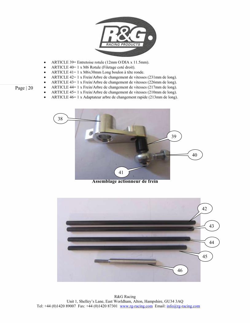
ARTICLE 39= Entretoise rotule (12mm O/DIA x 11.5mm).
ARTICLE 40= 1 x M6 Rotule (Filetage coté droit).
ARTICLE 41= 1 x M6x30mm Long boulon à tête ronde.
ARTICLE 42= 1 x Frein/Arbre de changement de vitesses (231mm de long).
ARTICLE 43= 1 x Frein/Arbre de changement de vitesses (226mm de long).
ARTICLE 44= 1 x Frein/Arbre de changement de vitesses (217mm de long).
ARTICLE 45= 1 x Frein/Arbre de changement de vitesses (210mm de long).
ARTICLE 46= 1 x Adaptateur arbre de changement rapide (213mm de long).
Assemblage actionneur de frein
38
39
40
41
42
43
44
45
46

R&G Racing
Unit 1, Shelley’s Lane, East Worldham, Alton, Hampshire, GU34 3AQ
Tel: +44 (0)1420 89007 Fax: +44 (0)1420 87301 www.rg-racing.com Email: [email protected]
Page | 21
Frein/Arbres de vitesses uniquement
Outils requis
Clés 10 et 12mm
Clé dynamométrique à 20Nm.
Clé Allen à 8mm A/F.
Réglages de couple M4 Boulon = 8Nm
M5 Boulon = 12Nm
M6 Boulon = 15Nm
M8 Boulon = 20Nm
Photo 1 Photo 2
PHOTO 3 PHOTO 4

R&G Racing
Unit 1, Shelley’s Lane, East Worldham, Alton, Hampshire, GU34 3AQ
Tel: +44 (0)1420 89007 Fax: +44 (0)1420 87301 www.rg-racing.com Email: [email protected]
Page | 22
PHOTO 5 PHOTO 6
PHOTO 7 PHOTO 8
PHOTO 9 PHOTO 10

R&G Racing
Unit 1, Shelley’s Lane, East Worldham, Alton, Hampshire, GU34 3AQ
Tel: +44 (0)1420 89007 Fax: +44 (0)1420 87301 www.rg-racing.com Email: [email protected]
Page | 23
PHOTO 11 PHOTO 12
PHOTO 13 PHOTO1 4
PHOTO 15 PHOTO 16

R&G Racing
Unit 1, Shelley’s Lane, East Worldham, Alton, Hampshire, GU34 3AQ
Tel: +44 (0)1420 89007 Fax: +44 (0)1420 87301 www.rg-racing.com Email: [email protected]
Page | 24
PHOTO 17 PHOTO 18
INSTRUCTIONS DE MONTAGE COTE LEVIER DE VITESSES
Enlever le carénage du bas
Enlever the le levier de vitesses d’origine/les boulons de fixation du repose pied (photo 1).
Enlever le levier de vitesses d’origine du support de boîte de vitesses (Photo 2 et 4).
Enlever la rotule d’origine (photo 3).
Installer le repose pied (Article 17) à l’aide du long boulon à tête ronde M6x15mm (Article 19) au
levier de vitesses (Article 16) (photo 5) (Il est conseillé d’utiliser un peu de frein filet pour fixer le
tout).
Placer la plus petite section bague ‘O’ (Article 10) autour du roulement en aluminium (Article 12)
(photo 6).
Placer le roulement avec la bague ‘O’ dans le levier de vitesses (Article 16) (photo 7).
Placer la plus large section bague ‘O’ (Article 9) dans le creux (photo 8).
Placer le long boulon à tête ronde M8x40mm (Article 18) à travers le support ajustable (Article 6)
(photo 9).
Placer l’assemblage de levier de vitesses autour de l’extrémité du boulon (Photo 10) (S’assurer
que la plus large section ‘O’ de la bague se place contre le support ajustable (Photo 9).
Placer le repose pied (Article 11) autour de l’extrémité du boulon puis serrer (photo 11).
(Il est conseillé d’utiliser un peu de frein filet pour fixer le tout).
Monter la plaque de talon (Article 8) en utilisant les 2 boulons à tête ronde M6x10mm (Article 7)
(Photo 12).
Installer le support d’ajustement au support principal (Article 3) en utilisant les 2 longs boulons à
tête ronde M8x20mm (Article 5) et les deux entretoises fines (Article 4) (photo 13).
Installer la rotule M6 d’origine (coté gauche) et le contre-écrou au levier de vitesse (Article 16)
avec un long boulon à tête ronde M6x15mm de long (Article 14) et la rondelle M6 (Article 15)
(Photo 14).
Monter l’ensemble aux supports d’origine avec les 2 longs boulons à tête ronde M8x30mm de
long (Article 2et les 2 principales entretoises de fixation (Article 1) (Photos 15 et 17) (Il est
conseillé d’utiliser un peu de frein filet pour fixer le tout).

R&G Racing
Unit 1, Shelley’s Lane, East Worldham, Alton, Hampshire, GU34 3AQ
Tel: +44 (0)1420 89007 Fax: +44 (0)1420 87301 www.rg-racing.com Email: [email protected]
Page | 25
Installer le levier de frein / de vitesses (Articles 42—45) à la rotule d’origine (photo 16) et à la
rotule d’origine installée au levier de vitesses (photos 14 et 18). Séléctionner l’arbre approprié
selon votre confort et la position que vous souhaitez.
Remettre le carénage du bas puis vérifier que les vitesses fonctionnent correctement.
Lorsque vous êtes satisfait, serrer tous les boulons et les écrous.
Spécial pour les changeurs rapides
PHOTO A1 PHOTO A2
PHOTO A3
Selon le modèle de moto vous devrez peut être utiliser l’adaptateur de changement rapide (Article
46) (Photos A1 and A2), vous devrez peut être aussi utiliser la petite entretoise d’origine et le long
boulon à tête ronde M6x20mm (Article 13) (Photo A3).

R&G Racing
Unit 1, Shelley’s Lane, East Worldham, Alton, Hampshire, GU34 3AQ
Tel: +44 (0)1420 89007 Fax: +44 (0)1420 87301 www.rg-racing.com Email: [email protected]
Page | 26
PHOTO 19 PHOTO 20
PHOTO 21 PHOTO 22
PHOTO 23 PHOTO 24

R&G Racing
Unit 1, Shelley’s Lane, East Worldham, Alton, Hampshire, GU34 3AQ
Tel: +44 (0)1420 89007 Fax: +44 (0)1420 87301 www.rg-racing.com Email: [email protected]
Page | 27
PHOTO 25 PHOTO 26
PHOTO 27 PHOTO 28
PHOTO 29 PHOTO 30

R&G Racing
Unit 1, Shelley’s Lane, East Worldham, Alton, Hampshire, GU34 3AQ
Tel: +44 (0)1420 89007 Fax: +44 (0)1420 87301 www.rg-racing.com Email: [email protected]
Page | 28
PHOTO 31 PHOTO 32
PHOTO 33 PHOTO 34

R&G Racing
Unit 1, Shelley’s Lane, East Worldham, Alton, Hampshire, GU34 3AQ
Tel: +44 (0)1420 89007 Fax: +44 (0)1420 87301 www.rg-racing.com Email: [email protected]
Page | 29
PHOTO 35 PHOTO 36
PHOTO 37 PHOTO 38
PHOTO 39 PHOTO 40

R&G Racing
Unit 1, Shelley’s Lane, East Worldham, Alton, Hampshire, GU34 3AQ
Tel: +44 (0)1420 89007 Fax: +44 (0)1420 87301 www.rg-racing.com Email: [email protected]
Page | 30
PHOTO 41 PHOTO 42
PHOTO 43 PHOTO 44
INSTRUCTIONS DE MONTAGE COTE FREIN
Enlever le carénage inférieur.
Enlever les boulons de fixation du repose pied d’origine (Photo 19).
Enlever le support de levier de frein d’origine (Photo 20).
Enlever la rondelle/entretoise du support de levier de frein d’origine (Photos 21, 22 et 23).
Enlever la bague ‘O’ (Photos 22 and 23).
Enlever le boulon de fixation de l’assemblage (Photos 23 et 24) (assurez vous que le second bague
‘O’ soit toujours en position sur le boulon de fixation (Photo 23).
Enlever le boulon d’origine de la rotule et l’actionneur de levier de frein (photo 24).
Enlever le boulon de pression de feu stop ajustable (photo 25).
Installer l’actionneur de rotule/frein et le boulon de pression de feu stop au nouveau support
d’actionneur (Article 38) (Photo 26).
Passer le boulon de fixation d’origine avec la bague d’origine ‘O’ dans le nouveau support
d’actionneur de frein (Photo 27).
Installer l’autre bague d’origine ‘O’ dans le creux (Photo 28).
Passer la rondelle/entretoise autour de l’extrémité du boulon ( Photo 29).

R&G Racing
Unit 1, Shelley’s Lane, East Worldham, Alton, Hampshire, GU34 3AQ
Tel: +44 (0)1420 89007 Fax: +44 (0)1420 87301 www.rg-racing.com Email: [email protected]
Page | 31
Placer l’ensemble en position puis serrer (Photo 30).
Assurez-vous que l’arbre actionneur de frein soit correctement aligné avec le maître cylindre et
que le ressort soit installé comme à l’origine (Photo 31).
Installer la nouvelle rotule et entretoise à l’aide d’un long boulon à tête ronde M6x30mm (Articles
39, 40 et 41) (Photo 32).
Installer le repose pied (Article 34) en utilisant le long boulon à tête ronde M6x15mm (Article 33)
au levier de vitesses (Article 24) (Photo 33) (Il est conseillé d’utiliser un peu de frein filet pour
fixer le tout).
Placer la petite bague ‘O’ (Article 22) autou du roulement en aluminium (Article 21) (photo 34).
Placer le roulement avec la bague ‘O’ dans le levier de vitesses (Article 24) (Photo 34).
Placer la bague large ‘O’ (Article 23) dans le creux (Photo 35).
Monter la plaque de talon (Article 27) en utilisant 2 long boulons à tête ronde M6x10mm (Article
26) (photo 36).
Placer le long boulon à tête ronde M8x40mm (Article 25) à travers le support ajustable (Article
28) (Photo 37).
Placer l’assemblage de levier de vitesses autour de l’extrémité du boulon (Photo 37) (Assurez vous
que la grosse bague ‘O’ se place contre le support ajustable (Photo 37).
Placer le repose pied (Article 20) autour de l’extrémité du boulon puis serrer (photo 38) (Il est
conseillé d’utiliser un peu de frein filet pour fixer le tout).
Installer l’assemblage de support ajustable sur le support principal (Article 32) en utilisant 2 longs
boulons à tête ronde M8x16mm (Article 29) (photo 40).
Installer la nouvelle rotule M6 (Coté gauche) et le contre écrou (Article 36) to au levier de vitesses
(Article 24) en utilisant le long boulon à tête ronde M6x15mm (Article 35) et la rondelle M6
(Article 37) (Photo 39).
Monter l’ensemble sur les supports d’origine en utilisant les 2 longs boulons à tête ronde
M8x35mm (Article 30) et les 2 principales entretoises de support (Article 31) (Photos 14 et 42) (Il
est conseillé d’utiliser un peu de frein filet pour fixer le tout).
Installer le levier de frein/ de vitesses (Articles 42—45) à la nouvelle rotule (Article 40) (Photo
43) et à l’autre nouvelle rotule (Article 36) installée au levier de vitesses (Photos 43 and 44).
Sélectionner l’arbre le plus approprié, selon le confort que vous désirez et de la position que vous
souhaitez.
Remettre le carénage inférieur puis verifier que chaque operation de freinage fonctionne.
Lorsque la position vous convient, serrez les boulons et les écrous.
IMPORTAN T: - Les instructions ci dessus ne sont qu’indicatives. Il est de votre responsabilité de vous assurer que l’ensemble des composant soient fixés et n’interfèrent pas avec d’autres parties de la moto. Ne pas effectuer les vérifications d’un bon fonctionnement général peut entraîner des blessures pour le motard, ou des dommages pour la moto.
Du fait de la complexité du montage et des risqué inhérents aux operations sur le système de
freinage, nous vous recommandons de faire monter les pièces R&G Racing par un
mécanicien qualifié.
ISSUE 1 18/07/2012 (NSY)

R&G Racing
Unit 1, Shelley’s Lane, East Worldham, Alton, Hampshire, GU34 3AQ
Tel: +44 (0)1420 89007 Fax: +44 (0)1420 87301 www.rg-racing.com Email: [email protected]
Page | 32
CONSUMER NOTICE
The catalogue description and any exhibition of samples are only broad indications of the Products and R&G may make design
changes which do not diminish their performance or visual appeal and supplying them in such state shall conform to the order. The
Buyer acknowledges no representation or warranty (other than as to title) has been given or will apply to the Products other than those in R&G’s order or confirmation and the Buyer confirms it has chosen the Products as being of merchantable quality and suitable for its
particular purposes. Where R&G fits the Products or undertakes other services it shall exercise reasonable skill and care and rectify
any fault free of charge unless the workmanship has been disturbed. The Buyer is responsible for ensuring that the warranty on the motorcycle is not affected by the fitting of the Products. On return of any defective Products R&G shall at its option either supply a
rePlacerment or refund the purchase money but shall not be liable if the Products have been modified or used or maintained otherwise
than in accordance with R&G’s or manufacturer’s instructions and good engineering practice or if the defect arises from accident or neglect. Other than identified above and subject to R&G not limiting its liability for causing death and personal injury, it shall not be
liable for indirect or consequential loss and otherwise its liability shall be limited to the amounts paid by the Buyer for the Products or
the fitting or service concerned. These terms do not affect the Buyer’s statutory rights.
R&G RACING RETURNS POLICY (NON-FAULTY GOODS)
Returns must be pre-authorised (if not pre-authorised the return will be rejected). Goods may only be returned direct to us if they were
purchased direct from us (customer must prove if necessary). Otherwise to be returned to original vendor. Goods must be in re-sellable condition, in the opinion of R&G Racing. All returns are subject to a 25% restocking and handling fee (25% of the gross value
exc. P&P – at the prevailing price at time of purchase). The customer must pay any and all carriage charges. No returns of
discontinued products, unless within 14 days of purchase. This policy does not affect your statutory rights and does not refer to faulty goods.


![DUCATI 1198 / 1198 S (2009) - JAMparts · PDF file6`gVedk^X Y#Y# '%%. Vaa g^\]ih gZhZgkZY DUCATI 1198 / 1198 S (2009) EVOLUTION EXHAUST SYSTEM Product code: (109190) S-D10EFT3T-ZC,](https://static.fdocuments.us/doc/165x107/5a78c5757f8b9a21538d2018/ducati-1198-1198-s-2009-jamparts-gvedkx-yy-vaa-gih-gzhzgkzy-ducati.jpg)