
Fishery Equipment and Hydraulic Engineer
125
1 Hauling device and hydraulic engineering for fishing boats Complied by Suthipong Thanasansakorn Khunhawat Manomayidthikarn Southeast Asian Fishery development Center, Training Department Thailand
-
Upload
hoangnguyen167 -
Category
Documents
-
view
218 -
download
0
Transcript of Fishery Equipment and Hydraulic Engineer

8/12/2019 Fishery Equipment and Hydraulic Engineer
http://slidepdf.com/reader/full/fishery-equipment-and-hydraulic-engineer 1/125
1
Hauling device and hydraulicengineering for fishing boats
Complied by
Suthipong Thanasansakorn
Khunhawat Manomayidthikarn
Southeast Asian Fishery development Center,Training Department Thailand

8/12/2019 Fishery Equipment and Hydraulic Engineer
http://slidepdf.com/reader/full/fishery-equipment-and-hydraulic-engineer 2/125
2
Forward
At present human resources and labor cost for onboard fishing activities is
serious situation. As recently auxiliary fishing machinery are used to or installed on
board fishing boats are being necessary for fishing vessels. Therefore, the
mounted of fishing machinery onboard is comforted while fishing operation at sea.
There are not only saving for labor cost, fishermen can get more profit during the
period at sea they are more time remains for fish preservation handling and net
or gears repairs.
Onboard fishing machinery is comes very important and quite difficulty
maters for handle by fishermen. However, SEAFDEC training department has
developed and promoted on sustain technique from simply local for small scale
fishing boats to commercial fishery in the Southeast Asian region from previous as
presently.
Thereby, the installation and utilize of an auxiliary fishing machinery and its
application of onboard in combine with simply or appropriate machine or
equipment should be impart and conveys to fishermen and technician concerned
in Southeast Asian Countries in order to handle of fishery machinery on board with
safe and capable to handle of maintenances and trouble shooting. In addition to
reduce of labor cost and number of personal on board on together with reliable
used with good performance at sea and no pollution impacts to the nature and
fishing ground.
Dr. Siri EkmaharajSecretary-general and
Chief of Training Department

8/12/2019 Fishery Equipment and Hydraulic Engineer
http://slidepdf.com/reader/full/fishery-equipment-and-hydraulic-engineer 3/125
3
Table of content
Page
Introduction to hauling device 4
Hand squid jigging 8
Simple winch 11
Methods of transmission power 13
Winch brake 18
Introduction to engine and power take-off 21
Planning for power take-off 23
V-belt drive 27
Chain drive 32
Flexible coupling 34
Clutch type 36
Hydraulic power source 41
Oil hydraulic pump and hydraulic motor 49
Precaution of hydraulic handling 61
Structure and principle of hydraulic motor 70
Hydraulic valve 79
Classification of directional control valve 102
Basic Design and Planning of hydraulic winch 121
SEAFDEC longline machinery 126

8/12/2019 Fishery Equipment and Hydraulic Engineer
http://slidepdf.com/reader/full/fishery-equipment-and-hydraulic-engineer 4/125
4
Manpower Source
1. Introduction
A hand hauling device may be regarded as any hand operated aid fitted to afishing boat which helps or assists the operator to make easier the setting orhauling of fishing gear. These devices may be divided into two groups:
- Any form of roller, drum or sheave used to assist in reducing friction as thefishing gear passes over the side of the boat. When the gear is being set orretrieved, the friction of the moving gear over the roller drum of sheave causesrotation of the device. This is a non-mechanical operation.
- Any machine enabling the fisherman to increase his hauling power by mechanicalmeans which as a result of his effort causes the fishing gear to be moved by areel, drum of sheave is called a hauler.
2. The simple devices
2.1. Roller
A simple roller to reduce the friction when handling fishing nets or ropes can beused in almost any type of fishing boat, depending on the size and stability of thecraft. The aid can be in the form of a wide or narrow roller to suit the fishing gear,
and may be fitted to a boat either at the bow, mid-ships or stern, or at a height tosuit the boat. As well as helping to reduce friction, it also changes the direction ofthe effort needed to lift the gear over the side of the boat.
On a craft of suitable stability the roller may be mounted on a bracket, so that theperson hauling pulls towards him rater than lifting upwards. The weight of hisbody is used to haul, rater than just the strength of his arms. See Fig. 1.3.
Fig. 1.3 pulling style without and with roller
The diameter of the roller should be as large as practical to reduce friction and
make it easier for the person pulling.
8/12/2019 Fishery Equipment and Hydraulic Engineer
http://slidepdf.com/reader/full/fishery-equipment-and-hydraulic-engineer 5/125
5
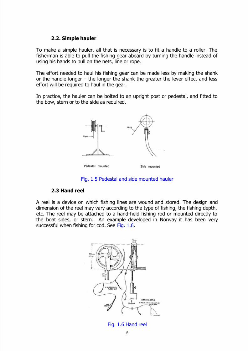
2.2. Simple hauler
To make a simple hauler, all that is necessary is to fit a handle to a roller. Thefisherman is able to pull the fishing gear aboard by turning the handle instead of
using his hands to pull on the nets, line or rope.
The effort needed to haul his fishing gear can be made less by making the shankor the handle longer – the longer the shank the greater the lever effect and lesseffort will be required to haul in the gear.
In practice, the hauler can be bolted to an upright post or pedestal, and fitted tothe bow, stern or to the side as required.
Fig. 1.5 Pedestal and side mounted hauler
2.3 Hand reel
A reel is a device on which fishing lines are wound and stored. The design anddimension of the reel may vary according to the type of fishing, the fishing depth,etc. The reel may be attached to a hand-held fishing rod or mounted directly tothe boat sides, or stern. An example developed in Norway it has been verysuccessful when fishing for cod. See Fig. 1.6.
Fig. 1.6 Hand reel

8/12/2019 Fishery Equipment and Hydraulic Engineer
http://slidepdf.com/reader/full/fishery-equipment-and-hydraulic-engineer 6/125
6
The reel can be manufactured from wood, aluminum, galvanized or stainless steeland secured to a tube clamped to or set into the gunwale of the boat. The centerbolt through the boss is used as a brake when paying out the line, and forclamping the reel when hauling in the trace.
2.4. Gurdy
A gurdy as used in part of Southwest England for mackerel fishing is a simplehand hauled reel for pulling in and storing mackerel long lines. It is made of awelded mild steel reel mounted on a short pedestal, which is clamped to thegunwale of the boat. The handle can be fitted to either side of the reel for left orright handed operation.
Fig. 1.8 Two gurdy on one boat
2.5. Hauler with hand rim
An alternative to a handle is to make a hauler with a larger diameter rim, whichcan be easily turned, hand over hand.
Fig. 1.9 Hauler with hand rim

8/12/2019 Fishery Equipment and Hydraulic Engineer
http://slidepdf.com/reader/full/fishery-equipment-and-hydraulic-engineer 7/125
7
2.6 Rectangular frame reel
A fishing reel does not have to be circular in shape, but may be made inrectangular form, with a central point and handle.
The pivot is fitted to a pedestal as shown in Fig 1.10.
Fig. 1.10 Rectangular hand reel
2.7. Pole or davit mounted hand reel
A hand reel may be fitted to a pole or davit and mounted on the side of a fishingboat so that the fishing line is haul clear of the boat sides by a pulley block fittedto the extended arms, as shown in Fig. 1.11.
Fig. 1.11 Pole or davit mounted hand reel

8/12/2019 Fishery Equipment and Hydraulic Engineer
http://slidepdf.com/reader/full/fishery-equipment-and-hydraulic-engineer 8/125
8
2.8. Metal reel and davit for deep water fishing
An example of a locally is made metal fishing reel and davit are shown in Fig. 1.14and 1.15.
Fig. 1.14 Detail of metal hand reel Fig. 1.15 Metal hand reeldavit
2.9. Hand squid jigging
Fishing for squid is carried out in various parts of the world; notably Japan, usinga method called “Jigging”.
Hooked lines being “jerked” so that the hooks tear into the body of the animalrather than the mouth, as with most other fish caught by hook catch squid. This
jerking a typical unit is shown in Fig. 1.16.
Fig. 1.16 Hand jigging reel system

8/12/2019 Fishery Equipment and Hydraulic Engineer
http://slidepdf.com/reader/full/fishery-equipment-and-hydraulic-engineer 9/125
9
2.10. Sheave
A solid hub of hardwood or cast aluminum, with a deep V-shaped groove ismachined so that it will grip the line, the groove being made to suit the thicknessof the line.
The shape of the sheave is important, and the dimensions have to be matched tothe size of line to be hauled. One method is to make the sheave up of two discs,bolted together by sandwiching a distance piece between them. Various thicknessof distance pieces may be added or taken away to suit lines of different sizes. Thesheave is made to turn from between 50-150 rpm as necessary to give therequired hauling speed in meters/min (or ft/min)
The diameter of the line to be hauled may range from 6 mm to 20 mm, dependingon the type of fishing.
The line is prevented from wrapping around the sheave by an “ejector-knife”which fits closely into the groove to lead the line off the sheave, and allow it tocoil down on the deck. The ejector-knife is often made from bronze to preventwear of the sheave.
Fig. 3.14 Line hauler sheave – two disctype
To improve the grip on the line a guide roller may befitted to increase amount of contact of the line withthe sheave. A second roller may also be added tofurther improve the grip, and to ensure that the lineleaves the sheave without wrapping around it. See Fig.1.20 and 1.21.
Fig. 1.20 Sheave with guide roller Fig. 1.21 Sheave with two rollers
Distance piece
(various thickness can be added
or taken away to suit size of line)
Ejector knife

8/12/2019 Fishery Equipment and Hydraulic Engineer
http://slidepdf.com/reader/full/fishery-equipment-and-hydraulic-engineer 10/125
10
2.11. Sheave with pressure roller
It is possible to obtain a positive grip on the line by fitting a covered rubber rolleras shown in Fig. 1.22. The roller is pressed on to the sheave, by mounting therubber roller on an ‘over-center’ lever, which exerts pressure on the line in the
sheave. The profile of the covered rubber roller must match the sheave, and fit asclosely as possible to prevent the line jumping between them.
Fig. 1.22 Sheave with pressure roller
2.12. Net drum
Fishing nets may be hauled in and stored on a hand operated drum, which can befitted to haul over the bow, sides or stern of the boat as required.
The fish have to be taken out of the net before it is reeled on the drum, so theremust be enough space to do this between the point where the net comes over theboat sides and the drum.

8/12/2019 Fishery Equipment and Hydraulic Engineer
http://slidepdf.com/reader/full/fishery-equipment-and-hydraulic-engineer 11/125
11
Fig. 1.23 Various installations of
net drum
2.13. Simple winch
The unit may be made of mild steel bar fitted with a slightly larger diameter pipeor hollow wooden handle, e.g. bamboo. The bar is bent into a crank supported bysimple bearings on each side. A drum of drums to wind the rope may be fittedinboard or outboard of the bearings, as prepared.
The unit may be bolted or screwed to the boat sides or made to drop into existingholes for rowlocks, if provided.
The rope may be hauled by passing a few turns around the drum, used as acapstan as in Fig. 1.26 or wound on the drum and stored as shown in Fig. 1.27and 1.28.
Fig. 1.26 Simple canoe winch Fig. 1.27 Reels of wooden construction,Note Oyster dredge in boat
Fig. 1.28 Reels with wooden hub andsteel frame
Fig. 1.29 Steel frame reel note simplemounting of unit into gunwale
c) Hauling over the side (port or starboard as preferred)

8/12/2019 Fishery Equipment and Hydraulic Engineer
http://slidepdf.com/reader/full/fishery-equipment-and-hydraulic-engineer 12/125
12
Fig. 1.30 Details of reel mounting
The method of operation is to use a light rope fastened to a large anchor at oneend, and to the hand winch at the other.
By dropping the anchor and paying out all the line, the boat, together with a smalloyster dredge is then hand-wound or cranked up to the anchor. In this way thedredge collects the oysters or shells until the boat are winched up to the anchor. Itis then lifted, reset, and the cycle starts again.
Fig. 1.31 Operation of Oyster dredge hand winch
2.14. Deck winch
A simple deck mounted hand winch for light loads may be made, as shown in Fig.1.32. This consists of two end brackets fastened to the deck and which supportthe shaft carrying the rope drum. A handle at each end of the shaft is used to turnthe winch and a chain or rope strop fastened at one end to the winch is loopedover the handle to stop the drum turning.

8/12/2019 Fishery Equipment and Hydraulic Engineer
http://slidepdf.com/reader/full/fishery-equipment-and-hydraulic-engineer 13/125
13
Fig. 1.32 A simple deck winch
2.15. Methods of transmission power
In order to handle more fishing gear or to fish at a greater depth a hand haulerwith gearing is required to be able to haul the increased weight. By using a handhauler designed to use a system of pulleys and belt, sprockets and chain or gearsit is possible to increase the effective hand power of the fisherman when hauling.
It is necessary to understand the basic principles involved and to be familiar withthe various components of any machine which will give a “mechanical advantage”.
1) Pulleys and Belt If two equal size pulleys are connected by a belt, andone pulley is turned by hand the other pulley will turn at the same speed.
Fig. 1.34 Equal size pulleys
If the pulleys are different size, connected by a belt and the large pulley A isturned, the smaller pulley B will turn faster. See Fig. 1.35.
Fig. 1.35 Different size pulleys
Conversely, if pulley B is turned, pulley A will run much more slowly. The object ofusing pulleys of different sizes is to improve the mechanical advantage of thehauler, to make it easier for the man hauling in the net or rope.

8/12/2019 Fishery Equipment and Hydraulic Engineer
http://slidepdf.com/reader/full/fishery-equipment-and-hydraulic-engineer 14/125
14
2) Sprockets and chain Exactly the same principle applies when using twosprockets and a chain as with two pulleys and a belt.
A large sprocket with 40 teeth connected by chain to a sprocket with 20 teeth willgive a ratio of 2:1.
Fig. 1.36 Reduction using chain and sprockets
3) Spur and helical gears The simplest type of gear is called a SPURgear, which means that the teeth are cut parallel to the shaft on which it fits.Simple spur gears as fitted to hand turned machinery are often heavy, and madefrom cast iron machined to produce the teeth. When two or more gears are to bemeshed together, the teeth on the gears must have the same shape and be thesame distance apart. If not they will not mesh properly and cannot be made towork.
Fig. 1.37 Spur gears Fig. 1.38 Helical gears
Helical gears have teeth cut at an angle to the shaft on which it fits, and the teeth
are cut in a curved shape. They run more smoothly than spur gears are moreexpensive and difficult to make. Helical gears and spur gears cannot be mixed ormeshed together.
Fig. 1.39 Simple reduction gear

8/12/2019 Fishery Equipment and Hydraulic Engineer
http://slidepdf.com/reader/full/fishery-equipment-and-hydraulic-engineer 15/125
15
In Fig. 1.39 (A) if a handle is fitted to the small gear wheel, the larger gear wheelturns at ¼ speed, the gear ratio is 4:1, and the hauler can pull four times theweight for the same effort. In (B), the ratio is only 3:1 so the hauler can pull threetimes the weight for the same effort.
4) Gear trains
Extra reduction can be made possibly by the use of another gear in the train. SeeFig. 1.40.
Fig. 1.40 Gear train
The ratio between gears A and B = 48:16, or 3:1The ratio between gears B and C = 16:8, or 2:1The overall ratio between A and C is 3*2 = 6:1
If gear C is turned 6 times, gear B will turn 3 times and gear A will turn one
revolution (once).
Note that gears A and C turn in the same direction.
The most common gear train design is using 4 gears, but with 2 of them on thesame shaft, so that they turn together (at the same speed) as in Fig. 1.41.
Fig. 1.41 Gear train with handle
The ratio between A and B = 4:1The ratio between C and D = 4:1The overall ratio = 4*4=16:1
Note: B and C turn at the same speed. A and D turn in the same direction.

8/12/2019 Fishery Equipment and Hydraulic Engineer
http://slidepdf.com/reader/full/fishery-equipment-and-hydraulic-engineer 16/125
16
In same case, a choice of cranking speed can be provided by fitting the handle onthe shaft carrying gears B and C. The handle will then have to be turned in theopposite direction. A second handle can be fitted on the other side of the winch itthe shaft through gear A is long enough.
Fig. 1.42 Principle of winch with reduction gear train
By applying the theory of gearing, as it is possible to design a more efficient handhauler, preferably on which can be built from parts available from local sources.
As the hauler or winch is developed and improved and improved from basicdesigns, it becomes necessary to provide the operator with additional controls toensure that the hauler can be used effectively and with safety.
Fig. 1.43 Geared hand hauler
One possible source for finding the reduction gears is to use oil engine parts. Onmany engines there is either a set of meshing gears, of a set of chain wheels andchain to drive the camshaft from the crankshaft. These are called the TIMINGGEARS or TIMING SPROCKETS AND CHAIN.

8/12/2019 Fishery Equipment and Hydraulic Engineer
http://slidepdf.com/reader/full/fishery-equipment-and-hydraulic-engineer 17/125
17
Fig. 1.44 Engine showed timing chain drive
If the chain drive type is to be used, the chain should run inside some kind ofcover so that it is kept oiled and therefore does not rust (especially when fishing insea water). This principle is shown in Fig. 1.45.
Fig. 1.45 Hand hauler using timing chain and sprockets
5) Pole or davit mounted hand reel A development of the simple hand reel is should in Fig. 1.46 so that the fishingline can be retrieved very quickly. The gear ratio between the two pulleys isdesigned so that the reel containing the line turns much faster than the pulleylifted with the handle. The drive from one pulley to the other is by belt.

8/12/2019 Fishery Equipment and Hydraulic Engineer
http://slidepdf.com/reader/full/fishery-equipment-and-hydraulic-engineer 18/125
18
Fig. 1.46 Pole mounted hand reel with belt drive
In this example there is very little weight or load on the fishing line, so the gearratio provides a ‘step’ as opposed to a step-down or reduction which is normallythe case.
6) Hand winch with reduction gear The winch consists of a framework of mild steel angle welded or bolted to a base.The winch drum is mounted on a large diameter shaft carried on a pair ofbearings, one on each side.
The drum may be of wood or mild steel tubing or fabricated by bending mild steelinto a cylinder and welding the seam. Flanges of mild steel are welded at each endof the tube, with the drum shaft passing through the center.
A large diameter gear is then bolted to one flange of the drum and concentric withit. A shaft with a bearing at each end and carrying a small diameter gear to meshwith the gear on the drum is bolted to the framework.
A reduction of from between 10:1 and 40:1 ratio, depending on the gears selectedor available may be achieved with two gear as shown in Fig. 1.47.
Fig. 1.47 Hand winch with reduction gear
7) Winch brake A brake is necessary to control the speed of paying out of the warp if the load isvery heavy. Very high speed paying out can be dangerous and it should becontrolled. Operator is easy to control it by using the lever acting on the drum,particularly if there is a ‘flywheel’ to the drum, or large flat surface on which a
brake can act. See Fig. 1.49.
Fig. 1.49 Brake lever acting on drum
Another type of brake used on larger winches utilizes a brake band around thesmooth surface of the flywheel. When the brake lever is applied (or a wheel
8/12/2019 Fishery Equipment and Hydraulic Engineer
http://slidepdf.com/reader/full/fishery-equipment-and-hydraulic-engineer 19/125
19
turned) the brake band clamps on to the flywheel. See Fig. 1.50. A brake levermay be hand or foot operated.
Fig. 1.50 Brake band acting on drum
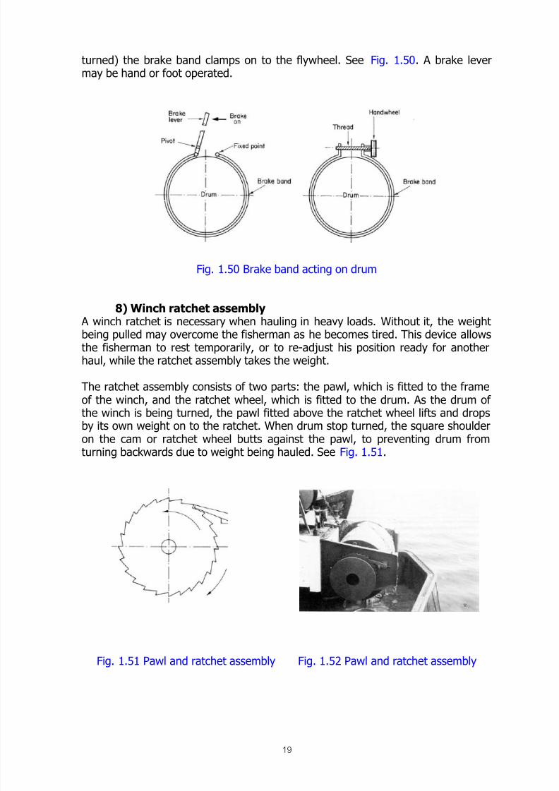
8) Winch ratchet assembly A winch ratchet is necessary when hauling in heavy loads. Without it, the weightbeing pulled may overcome the fisherman as he becomes tired. This device allowsthe fisherman to rest temporarily, or to re-adjust his position ready for anotherhaul, while the ratchet assembly takes the weight.
The ratchet assembly consists of two parts: the pawl, which is fitted to the frameof the winch, and the ratchet wheel, which is fitted to the drum. As the drum of
the winch is being turned, the pawl fitted above the ratchet wheel lifts and dropsby its own weight on to the ratchet. When drum stop turned, the square shoulderon the cam or ratchet wheel butts against the pawl, to preventing drum fromturning backwards due to weight being hauled. See Fig. 1.51.
Fig. 1.51 Pawl and ratchet assembly Fig. 1.52 Pawl and ratchet assembly
8/12/2019 Fishery Equipment and Hydraulic Engineer
http://slidepdf.com/reader/full/fishery-equipment-and-hydraulic-engineer 20/125
20
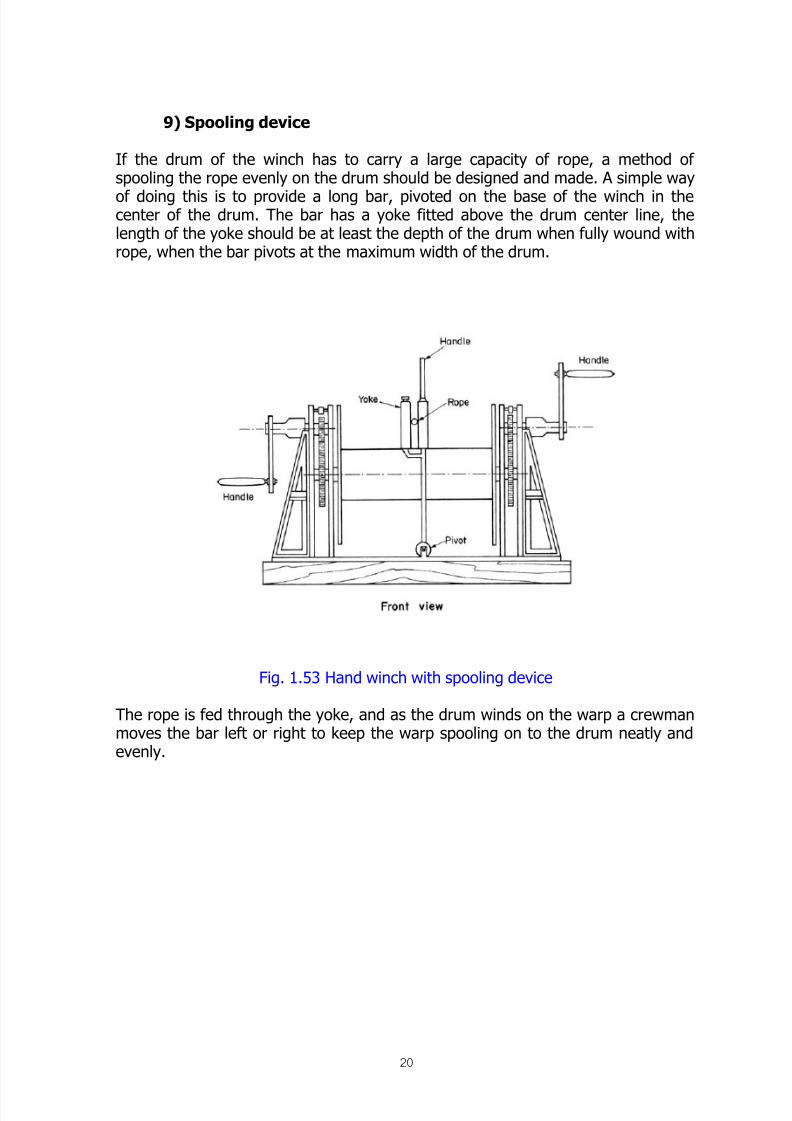
9) Spooling device
If the drum of the winch has to carry a large capacity of rope, a method ofspooling the rope evenly on the drum should be designed and made. A simple way
of doing this is to provide a long bar, pivoted on the base of the winch in thecenter of the drum. The bar has a yoke fitted above the drum center line, thelength of the yoke should be at least the depth of the drum when fully wound withrope, when the bar pivots at the maximum width of the drum.
Fig. 1.53 Hand winch with spooling device
The rope is fed through the yoke, and as the drum winds on the warp a crewmanmoves the bar left or right to keep the warp spooling on to the drum neatly andevenly.

8/12/2019 Fishery Equipment and Hydraulic Engineer
http://slidepdf.com/reader/full/fishery-equipment-and-hydraulic-engineer 21/125
21
IC Engine Power Source
1. Introduction
The use of hand hauling devices is a very useful and often necessary ‘first step’ inthe improvement of traditional fishing methods.
However, in many cases the development can be carried further by using anengine to drive a hauling device, instead of using manpower. This opens up amush wider range of fishing methods and gear available to the fisherman so thathe can then consider the use of more nets, longer lines, even a different type offishing operation as a result of having a powered hauler.
One of the disadvantages of an engine driven hauling device is the increased costinvolved in buying the equipment, particularly if it is made in another counter andhas to be paid for in foreign currency. In order to get around the problems of highcost and any exchange controls involving foreign currency, it may be possible toproduce the equipment locally.
It is necessary therefore to consider various basic ideas of hauler designs and theircomponents, so that a suitable machine can be made. Powered haulers can bedivided into two main types:-
a) Driven from the main engine of the fishing boat by a power-take-offsystem (P.T.O. drive); The advantage of the hauler driven by the main engine is
that there is no need to by and maintain another engine. The drive arrangement istaken of the engine in such a way that it can be ‘clutched’ in or out of drive by theoperator, leaving the engine free to drive the boat in the normal wayindependently of the hauler.
With this type of drive the installation may by more complicated and the haulercan only be used in one (fixed) position in the vessel. There are some limitationswith its use, as the engine drives either the hauler or the propeller shaft or both atonce. The operator does not have the choice of independent speed variations; forexample, he cannot make the propeller shaft turn slowly and at the same timespeed the hauler up to run fast, or vice versa. If the engine runs fast, the hauler
and the propeller shaft (when in gear) will also run fast.
b) Driven by separate engine completely independent of the main engine ofthe fishing boat.
The advantages of this type of hauler are that:-
1) The operator can have total control over the speed at which the fishing gear isbeing hauled, independent of the main engine and therefore the speed of theboat;
2) The engine and hauler can be in a unit, and moved to various places on theboat to suit the fishing operation.

8/12/2019 Fishery Equipment and Hydraulic Engineer
http://slidepdf.com/reader/full/fishery-equipment-and-hydraulic-engineer 22/125
22
The disadvantage is that there is another engine to buy, start and maintain. Ahauler engine is usually fairly small, and often small engine s are not so robust,can be temperamental to start and are exposed (on deck) to corrosion anddamage.
2. Power take-off (P.T.O)
Power take-off (P.T.O) is the method by which power to drive auxiliary equipmentis taken partly from the engine used for main propulsion purposes. In a marineapplication, the engine is installed primarily to propel the vessel by driving thepropeller shaft and propeller, any other power required for auxiliaries, winch, nethauler, etc., may be derived from the engine by means of a P.T.O.
In practice, power is taken off an engine in the following ways:-1) The front of crankshaft2) The extended camshaft (at haft engine crankshaft speed)3) The flywheel4) The power take-off points with clutch (fitted to the engine before deliver)
1) Crankshaft
On many engines the crankshaft is extended forward outside the engine casing toenable a drive to be take of. The crankshaft is usually provided with a parallel keyway, so that a V-pulley, flat belt pulley or clutch unit can be attached and driven.See Fig. 2.1.
Fig. 2.1 Crankshaft extension
2) Camshaft
Many smaller engines have a long extension camshaft outside the engine casing
which is keyed in the same manner as the crankshaft extension. If is important toremember that the camshaft turns at half engine speed. For example, on anengine that runs at 2000 rpm. the camshaft would turn at 1000 rpm. On someengines the camshaft is gear driven and therefore turns in the opposite directionof rotation (D.O.R.) to the crankshaft.
Fig. 2.2 Camshaft extension
8/12/2019 Fishery Equipment and Hydraulic Engineer
http://slidepdf.com/reader/full/fishery-equipment-and-hydraulic-engineer 23/125
23
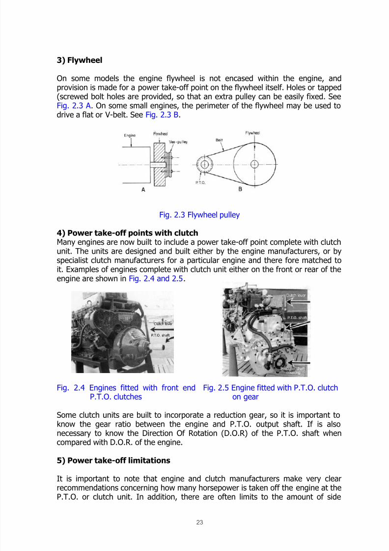
3) Flywheel
On some models the engine flywheel is not encased within the engine, andprovision is made for a power take-off point on the flywheel itself. Holes or tapped
(screwed bolt holes are provided, so that an extra pulley can be easily fixed. SeeFig. 2.3 A . On some small engines, the perimeter of the flywheel may be used todrive a flat or V-belt. See Fig. 2.3 B.
Fig. 2.3 Flywheel pulley
4) Power take-off points with clutchMany engines are now built to include a power take-off point complete with clutchunit. The units are designed and built either by the engine manufacturers, or byspecialist clutch manufacturers for a particular engine and there fore matched toit. Examples of engines complete with clutch unit either on the front or rear of theengine are shown in Fig. 2.4 and 2.5.
Fig. 2.4 Engines fitted with front endP.T.O. clutches
Fig. 2.5 Engine fitted with P.T.O. clutchon gear
Some clutch units are built to incorporate a reduction gear, so it is important toknow the gear ratio between the engine and P.T.O. output shaft. If is alsonecessary to know the Direction Of Rotation (D.O.R) of the P.T.O. shaft whencompared with D.O.R. of the engine.
5) Power take-off limitations
It is important to note that engine and clutch manufacturers make very clearrecommendations concerning how many horsepower is taken off the engine at theP.T.O. or clutch unit. In addition, there are often limits to the amount of side

8/12/2019 Fishery Equipment and Hydraulic Engineer
http://slidepdf.com/reader/full/fishery-equipment-and-hydraulic-engineer 24/125
24
loads, which may be exerted on the engine crankshaft, crankshaft and camshaftextensions, P.T.O. clutches, etc.
When a flat or V-belt pulley is fitted to the engine and belts are tensioned in orderto drive the hauling equipment. The side thrusts may be so considerable thatsevere damage to the crankshaft, camshaft or P.T.O. clutch bearings and oil seals
may result unless the installation is correctly designed for the expected loading.
The method of preventing damage by side loads on the engine unit is to install ashort P.T.O. lay-shaft driven directly through a flexible coupling, with the lay-shaftmounted on heavy duty bearings which are capable of taking the excessive loadcaused by belt tensioning and transmission of power.
6) Planning for power take-off drives
When planning the type and layout of the power take-off train the following pointshave to be taken into consideration:-
- The engine speed and required winch driving shaft speed (or drum speed)must be known so that the correct reduction gears and pulleys may becalculated and fitted;
- The power required from the engine and the arrangement of the P.T.O. and
whether a short P.T.O. lay-shaft is required;- The required type of drive, whether totally by flat belt, V-belt or chain drive or
by a mixture of these types. This decision is dependent upon the availability oflocal materials, or which type best suits the application and cost;
- It is preferable to design a system where there is as little machinery as
possible turning when the P.T.O. is not in use. Avoid putting the only clutchafter the belt drive to the overhead lay shaft’ it is better to have two clutches,one to drive the lay-shaft, and one to drive the deck machinery;
- The position of the winch or deck machinery. This subject is dealt with under “Winch Positions” later;
- Plan to locate shafting and belt drives so that they leave as much usable space
on board as possible, while at the same time allowing accessibility for servicingand repair;
- When the engine has to be aligned to the propeller shaft the movementrequired will affect the alignment of the P.T.O. belt and overhead lay-shaft. Ifis important that belt pulleys on the engine P.T.O. and the lay-shaft are in line
and parallel. If not, a flat belt will not stay on the pulleys, and Vee-belts, chainsand sprockets will wear quickly;
- Provide adjustment for all belts. This may be done by a jockey clutch pulley, bya belt tension pulley only, or by slotted holes to allow movement;
- There should be a universal or flexible joint between the overhead lay-shaftarrangement and winch. This should take up any slight misalignment betweenthe two units in use. An alternative to a flexible joint is a belt or chain drivefrom the lay-shaft to the winch/deck machinery;
- Provide adjustment for all belts. This may be done by a jockey clutch pulley, bya belt tension pulley only, or by slotted holes to allow movement;
-
The controlling lever for the drive clutch to the winch/deck machinery must beclose to the other controls, so that the operator can disengage the drivequickly in an emergency;

8/12/2019 Fishery Equipment and Hydraulic Engineer
http://slidepdf.com/reader/full/fishery-equipment-and-hydraulic-engineer 25/125
25
- All shafting, belts and pulleys should be fitted with guards to prevent the crewfrom becoming entangled in the machinery when it is running.
a) drive to winch by overhead lay-shaft, clutch control in wheelhouse
b) Direct drive to winch, clutch and controls on deck
c) Clutch forward of engine, clutch control on deck
Fig. 2.6 Various PTO/Winch drives
3. Flat belt drive
A flat belt may be used to transmit power from an engine to a hauling device. It isa very practical and inexpensive method of drive but does have some limitations in
use.
The flat belt drive installation is most suitable in the following situations:-- When the distance between the engine and hauler pulleys is greater than
about 1.20 m (4 feet)- When the reduction between the engine and hauler pulleys is small, about 1:2.
Large reductions may be made only if the distance between pulley centers islong, more than 2.40 m (8 feet);
- When a degree of belt slip is acceptable;- When a jockey pulley clutch is required.
Advantages:-

8/12/2019 Fishery Equipment and Hydraulic Engineer
http://slidepdf.com/reader/full/fishery-equipment-and-hydraulic-engineer 26/125
26
- Not suitable when there is a short distance between engine and hauler pulleys,as it is then difficult to get sufficient tension on the drive belt to obtain a goodgrip. The weakest point of the belt when being tensioned is usually at the join;
- A flat belt drive cannot be used in an oily situation;- Alignment must be very accurate otherwise the belt will run off the pulleys.
Fig. 2.7 Jockey pulley – flat belt drive
Installation of flat belts
When designing an installation it is most important to ensure correct alignment ofpulleys, which must be parallel. Provision must be made for adjustment of belts. Ifa jockey clutch is being used, the same jockey pulley arrangement is used both forthe clutching operation and belt tension. All belts must be fitted with belt guardsto prevent clothing and hands being caught in revolving shafts.
The choice of the correct size pulleys and belt width must be made to transmit thepower available at the correct speed for the hauling operation. Fig. 2.7 shows atypical flat belt drive installation.
Adjustment of flat belts
In any installation using driving belts there must be provision made for adjustmentas all belts stretch in service. Initially, a flat belt may stretch considerably in whichcase it is practical to shorten it by cutting off the surplus and fitting a new beltfastener to one end. Once the belt has ‘run-in’ it will require adjustment lessfrequently.
In the case of a flat belt drive to a small unit, for example, a generator, which canbe moved slightly without affecting other installed equipment, belt adjustmentmay be achieved by slotted holes in the base of the unit permitting somemovement to tighten the belt. See Fig. 2.11.

8/12/2019 Fishery Equipment and Hydraulic Engineer
http://slidepdf.com/reader/full/fishery-equipment-and-hydraulic-engineer 27/125
27
Fig. 2.11 Adjustment of flat belt
In a typical winch installation however, this in normally not practical, as the engineis in a fixed position relative to the propeller shaft, and the winch is securelymounted on deck. Belt adjustment is most often achieved by the use of a jockey
or idler pulley acting on the SLACK side of the belt.
The jockey pulley is more effective if fitted as close as practical to the drivingpulley to assist the belt to ‘wrap around’ it and so providing better grip. The jockeyis fitted to the outside of the belt as shown in Fig. 2.12 (b).
If the belt is adjusted by fitting the jockey on the inside of the belt the drive is notso positive. The jockey pulley lifts the belt away from the engine driving pulley andreduces the ‘area of contact’ of the belt with the pulley which leads to belt slip.See Fig. 2.12 (a) and (c).
Fig. 2.12 Adjustment of flat belt by jockey pulley
4. V-belt drive
The V-belt drive system has been developed to provide an alternative to the flatbelt system and may be used to advantage in the following types of installation:-- Where the distance between pulley centers is shorter than is possible with a
flat belt drive;
-
Where a greater reduction ratio between the engine and hauler is required.This is possible provided there is sufficient distance between centers. If there isa very large difference in pulley sizes on a short belt run the belt will not grip

8/12/2019 Fishery Equipment and Hydraulic Engineer
http://slidepdf.com/reader/full/fishery-equipment-and-hydraulic-engineer 28/125
28
the small pulley sufficiently, as there is not enough belt in contact with thepulley;
- Where greater power is required and can be transmitted by using matched setsof multiple belts;
V-belts are more tolerant of slight misalignment although this can cause excessive
belt wear.
Disadvantages:- V-belts are more difficult to replace if either pulley is fitted between
components which have to be removed before the belts can be slipped overthe shaft. This can be a long operation which may result in fishing gear infishing gear or catch being lost if a breakdown occurs whilst hauling;
- Belts in a multiple belt drive have to be replaced in complete sets if onebecomes broken or damaged, which can prove to be expensive;
- A jockey pulley clutch cannot be used on V-belts except in the case of a singlebelt drive off a small engine.
Installation
Correct alignment is very important with V-belts. Shafts must be parallel andpulleys exactly in line otherwise the shanks of the belt will ware quickly. Provisionmust be made for adjustment to prevent the belt slipping and overheating. A
jockey pulley is the usual method of belt adjustment in a hauler installation, but V-belts cannot be fitted with a jockey pulley clutch. Some other clutching devicemust be fitted, either at the engine or at the hauler itself. All belts and pulleysmust be guarded as with flat belts. The careful choice of V-belt pulleys, numbers
of V-belts in the drive and the section of belts to be used is advised to ensure theavailable power and speeds may be transmitted without belt slip. Fig. 2.13 showsa typical drive arrangement, but with out jockey pulley adjustment.
Fig. 2.13 Typical v-belt drive
Vee belts are made in various sizes and widths, and numbered according ot thecross-section of the belt as shown in Fig. 2.14.

8/12/2019 Fishery Equipment and Hydraulic Engineer
http://slidepdf.com/reader/full/fishery-equipment-and-hydraulic-engineer 29/125
29
Fig. 2.14 Cross section of v-belts
Recent changes in the measurement of V-belts have been introduced. Imperialsizes in inches are no longer made, all new classification being in metric sizes. Asthere are still many Imperial sizes in stocks around the world, they have beenincluded for purposes of recognition.
Belts are measured by inside length and usually have the cross-section size andlength stamped or printed on them, for example:-
A 3490 (millimeters) or A 136 (inches)
The above example shows that the belt has an A cross-section, and that it is 3490mm long (136”) when measured from the inside.
The method for working out the length of a V-belt is as follows:-a) take a length of soft wire or string (that does not stretch);b) lead it over the pulleys (in the grooves) and mark the wire or string as shown
below;c) Measure the total length of the wire or string to the mark.
Note: Any adjustment pulleys or slotted adjustment bolts must be loosened, so
that the SHORTEST belt length is being measured.

8/12/2019 Fishery Equipment and Hydraulic Engineer
http://slidepdf.com/reader/full/fishery-equipment-and-hydraulic-engineer 30/125
30
Standard lengths of V-belts:
When planning the layout of an installation, it is possible, by being aware of thestandard belt sizes, to place the components to suit the length of standard belts.
This improves the spare parts availability for the future. A list of standard length V-belts is given in Table 1.
Table 1 Standard length of v-belt
Adjustment of V-belt drives
Similar principles apply concerning the adjustment of V-belts as with flat belts. Adjustment may be achieved by moving one unit, usually the driven unit, byslotted holes in the base.
On a winch drive installation adjustment by jockey pulley is more common byfitting the jockey to act on the INSIDE of the belt. However, it is quite acceptableto adjust the belt by a jockey on the OUTSIDE of the belt, but by using a differenttype of pulley.

8/12/2019 Fishery Equipment and Hydraulic Engineer
http://slidepdf.com/reader/full/fishery-equipment-and-hydraulic-engineer 31/125
31
Inside adjustment: A V-pulley is fitted as near to the LARGER pulley as practical,acting on the inside of the belts. See Fig. 2.18 (a).
a) Inside adjustment Jockey as near aspractical to larger pulley
b) Outside adjustment Jockey within1/3 of total distance between centers,near to engine pulley
Fig. 2.18 Methods of rotation
Outside adjustment: A Flat pulley is fitted within 1/3 of the total distance betweenpulley centers from the DRIVING (engine) pulley acting on the outside or back ofthe belts. Excessive pressure on the back of the belt causes fatigue and
overheating leading to early wear. This is because the belt has to flex first in onedirection around the V-pulleys and then in the other direction around the flatpulley. This is called DEFLECTION. See Fig. 2.18 (a) and (b).
Adjustment of V-belts in a multiple belt drive is quite difficult, as it is necessary toensure that there is even tension acting on all belts. Uneven tension is caused bythe jockey pulley being out-of-parallel with the belts and pulley and results in thebelts on one side being stretched to much. Eventually the stretched belt will notdrive and the complete set of belts must be changed. Similar problems occur ifthere is major misalignment of any of the shafts or pulleys, as the belts ‘scuff’ andoverheat.
It is important to note that with multiple belts the correct number of belts shouldalways be used. In the event that one-belt breaks the strain placed on theremaining belts in the drive will cause them to fail very early. Never add one newbelt to a set of used, and therefore partly worn, belts.
5. Timing belt drives
A more recent concept in driving machinery, the timing belt drive design uses aflat rubber-type belt with the underside having flat square ‘teeth’ or notches. The
pulleys over which the belt runs also have notches into which the belt fits. It is avery positive like chain, but being slightly elastic it is very smooth and quiet andneeds not lubrication. Another good feature is that once the belt has beenadjusted on installation, no other adjustment is necessary. Depending on shaft

8/12/2019 Fishery Equipment and Hydraulic Engineer
http://slidepdf.com/reader/full/fishery-equipment-and-hydraulic-engineer 32/125
32
speed of the machinery concerned, power drives up to 100 horsepower arepossible with the correct timing belt.
6. Chain drive
In some applications it may be considered preferable to drive deck machinery bychain rather than by flat or V-belts.
The main advantage is that a chain drive is very positive, and there is no slipbetween chain and chain sprockets. Positive drive is achieved without the tension,which is necessary on a flat or V-belt drive installation to ensure that no slip takesplace.
Chain drive is particularly suitable for slow speed power transmission and betweenengine and hauler or winch when close together. It is not suitable for very longlengths of drive, or for very high-speed applications, because of the difficulty ofguarding the chain to prevent accident to the fishermen.
Corrosion by salt water is a major factor to consider when planning an installationusing chain in an exposed position. Ideally, all chain drives should run in an oilbath for correct lubrication and protection, but often this is not practical.
Chains in exposed conditions should be heavily grease for lubrication andprotection against corrosion, and inspected frequently to ensure that rollers andlinks have not seized up with rust. A chain drive lying idle for long periods inexposed conditions will rust very badly and often break when next used. To
prevent this, the chain can be removed beforehand, and left soaking in oil whilethe boat is not being used.
Installation of chain drive
Chain drives can be used easily in practically any position, with the exception of avertical drive, which can be more difficult to install.
Alignment is again very important, all shafts and sprockets should be parallel andin line. The slack side of the chain can be very dangerous to the crew if it is
allowed to become to slack when running fast. Fitting idler sprockets on the slackside of the chain, either on the inside or outside as preferred may tension thechain.
A clutch of the jockey type cannot be used with chain, therefore some otherclutching device must be used either at the engine or hauler.
As with flat and V-belt drives all chains should be guarded. Any chain drive fittedwith an oil bath will not need further guarding. The choice of correct size of chainand sprockets must be very carefully made to ensure that the drive can betransmitted. Fig. 2.22 shows a simple chain drive installation.

8/12/2019 Fishery Equipment and Hydraulic Engineer
http://slidepdf.com/reader/full/fishery-equipment-and-hydraulic-engineer 33/125
33
Fig. 2.22 Simple chain drive installation
Adjustment of chain
Principle of adjustment is very similar to those of V-belts. Adjustment may beachieved by moving the driven unit by slotted holes in the base, as shown in Fig.
2.25 (a). An alternative method by the use of idler sprockets is more normallyused, idler sprockets being fitted to the slack side of the chain. Typical positionsfor various designs of idler are shown in Fig. 2.25 (b). A chain idler may be fittedwith a spring to maintain an even pressure on the chain and reduce chain whip.
Fig. 2.25 Methods of chain Adjustment
Chain tension should befairly tight when installed,with only a small amount
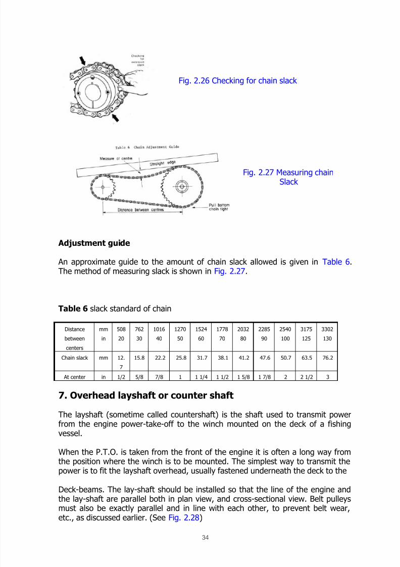
of slack. New chains willloosen slightly and once the initial stretch has occurred there will be much lessadjustment required. Chain tension is checked as shown in Fig. 2.26 and 2.27.
8/12/2019 Fishery Equipment and Hydraulic Engineer
http://slidepdf.com/reader/full/fishery-equipment-and-hydraulic-engineer 34/125
34
Fig. 2.26 Checking for chain slack
Fig. 2.27 Measuring chainSlack
Adjustment guide
An approximate guide to the amount of chain slack allowed is given in Table 6.The method of measuring slack is shown in Fig. 2.27.
Table 6 slack standard of chain
Distance
between
centers
mm
in
508
20
762
30
1016
40
1270
50
1524
60
1778
70
2032
80
2285
90
2540
100
3175
125
3302
130
Chain slack mm 12.
7
15.8 22.2 25.8 31.7 38.1 41.2 47.6 50.7 63.5 76.2
At center in 1/2 5/8 7/8 1 1 1/4 1 1/2 1 5/8 1 7/8 2 2 1/2 3
7. Overhead layshaft or counter shaft
The layshaft (sometime called countershaft) is the shaft used to transmit powerfrom the engine power-take-off to the winch mounted on the deck of a fishingvessel.
When the P.T.O. is taken from the front of the engine it is often a long way fromthe position where the winch is to be mounted. The simplest way to transmit thepower is to fit the layshaft overhead, usually fastened underneath the deck to the
Deck-beams. The lay-shaft should be installed so that the line of the engine and
the lay-shaft are parallel both in plan view, and cross-sectional view. Belt pulleysmust also be exactly parallel and in line with each other, to prevent belt wear,etc., as discussed earlier. (See Fig. 2.28)

8/12/2019 Fishery Equipment and Hydraulic Engineer
http://slidepdf.com/reader/full/fishery-equipment-and-hydraulic-engineer 35/125

8/12/2019 Fishery Equipment and Hydraulic Engineer
http://slidepdf.com/reader/full/fishery-equipment-and-hydraulic-engineer 36/125
36
Fig. 2.33 Flexible rubber coupling
Flexible disc coupling
On small engine and hauler installations the flexible coupling may be made up outof a disc of thick rubber or canvas/rubber material as used on flat belts. Holes arecut in the disc in opposite pairs at 90° to each other. (See Fig. 2.34)
Fig. 2.34 Flexible disc coupling
Vehicle propeller shaft coupling
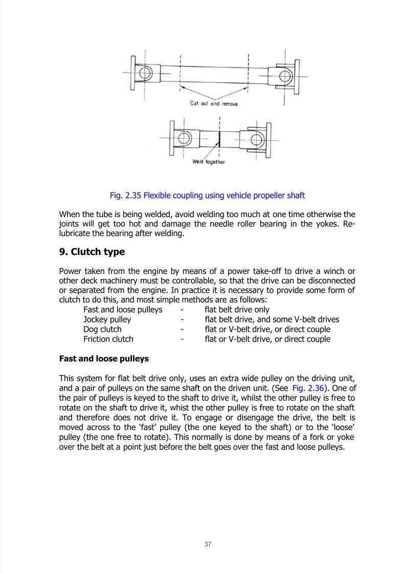
A simple flexible coupling may be made from a vehicle propeller shaft of the type
shown in Fig. 2.35. A typical propeller shaft consists of a tube, with a universalyoke joint at each end, at right angles to each other.
Cutting the tube in two places, removing the central cutout portion, and weldingtogether the end sections with the yoke joints complete makes a coupling.
It is important to ensure that the tubes are welded together so that the yokes areat right angles to each other, as they were before the propeller shaft was cut. Thisallows the joints to work with the maximum amount of movement withoutstraining the bearings, and also to balance the unit to cut down vibration.
8/12/2019 Fishery Equipment and Hydraulic Engineer
http://slidepdf.com/reader/full/fishery-equipment-and-hydraulic-engineer 37/125
37
Fig. 2.35 Flexible coupling using vehicle propeller shaft
When the tube is being welded, avoid welding too much at one time otherwise the joints will get too hot and damage the needle roller bearing in the yokes. Re-lubricate the bearing after welding.
9. Clutch type
Power taken from the engine by means of a power take-off to drive a winch orother deck machinery must be controllable, so that the drive can be disconnectedor separated from the engine. In practice it is necessary to provide some form of
clutch to do this, and most simple methods are as follows:Fast and loose pulleys - flat belt drive onlyJockey pulley - flat belt drive, and some V-belt drivesDog clutch - flat or V-belt drive, or direct coupleFriction clutch - flat or V-belt drive, or direct couple
Fast and loose pulleys
This system for flat belt drive only, uses an extra wide pulley on the driving unit,and a pair of pulleys on the same shaft on the driven unit. (See Fig. 2.36). One ofthe pair of pulleys is keyed to the shaft to drive it, whilst the other pulley is free torotate on the shaft to drive it, whist the other pulley is free to rotate on the shaftand therefore does not drive it. To engage or disengage the drive, the belt ismoved across to the ‘fast’ pulley (the one keyed to the shaft) or to the ‘loose’pulley (the one free to rotate). This normally is done by means of a fork or yokeover the belt at a point just before the belt goes over the fast and loose pulleys.

8/12/2019 Fishery Equipment and Hydraulic Engineer
http://slidepdf.com/reader/full/fishery-equipment-and-hydraulic-engineer 38/125
38
Fig. 2.36 Fast and loose pulley arrangement
Jockey pulley clutch
A jockey pulley is used to tighten the flat belt between the driving and drivenpulleys to provide a positive drive. By slackening the jockey pulley the belt is tooloose to transmit any power between the engine pulley and the driven machinery,so providing a clutch.
The jockey pulley is considered to be most effective if it is made to act on theoutside of the belt, against the slack side. It should be positioned close to theengine-driving pulley to assist in making the belt “wrap” around it to provide a
more positive grip.
The system is suitable for a flat belt drives system and should not be used withmultiple V-belts. However, low HP applications with a single V-belt are possible.
The jockey pulley may be tensioned by a spring to add against the belt when inthe ‘drive’ or clutch-in position. This helps to maintain an even pressure on thebelt even if it stretches slightly. An operating handle or lever is connected to the
jockey pulley so that the operator can control the drive from a position CLOSE to
the controls of the winch or deck machinery being driven.

8/12/2019 Fishery Equipment and Hydraulic Engineer
http://slidepdf.com/reader/full/fishery-equipment-and-hydraulic-engineer 39/125
39
It is most important that the clutch lever can be reached quickly by the operator,to avoid accidents. The operating lever should be designed so that when thewinch or deck gear drive is engaged there are no pins or locking devices to beremoved before ‘clutching out’.
Fig. 2.37 Jockey pulley clutch
For reasons of safety, all pins or locking devices should be fitted to keepmachinery in the ‘no-drive’ or ‘clutch-out’ position only, not in the ‘clutch-in’position.
Dock Clutch
A dog clutch is a mechanical unit fitted between the engine and the power take-offto allow the drive to the winch, etc., to be disconnected or connected as required.
In normal use the dog clutch can be engaged only when the engine is stopped. Any attempt to engage the drive while the engine is running will result in damageeither to the dog clutch or the driven equipment. If can be disengaged whilst theengine is running. A typical dog clutch arrangement is shown in Fig. 2.38.

8/12/2019 Fishery Equipment and Hydraulic Engineer
http://slidepdf.com/reader/full/fishery-equipment-and-hydraulic-engineer 40/125
40
Fig. 2.38 Simple dog clutch
Friction clutch
The friction clutch is a similar unit to a dog clutch, except that the engagementbetween the driving and driven units is by a friction disc or discs instead of thedog clutch. The friction disc drive is very much smoother, and the unit is designedto be clutched in or out of drive whilst the engine is running, and does sosmoothly without shock to the driven gear.
Fig. 2.39 Parts of a motor vehicle friction clutch
8/12/2019 Fishery Equipment and Hydraulic Engineer
http://slidepdf.com/reader/full/fishery-equipment-and-hydraulic-engineer 41/125
41
Hydraulic Power Source
1. Basic knowledge
1.1. What is oil hydraulics?
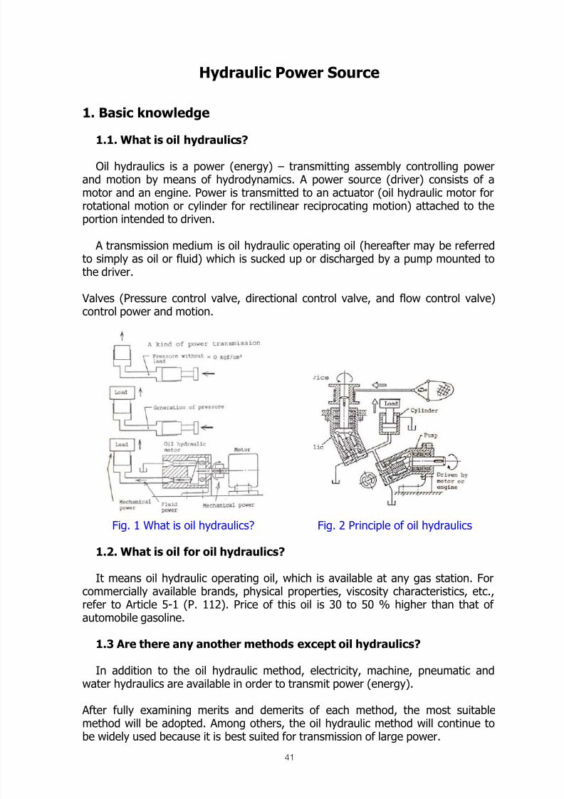
Oil hydraulics is a power (energy) – transmitting assembly controlling powerand motion by means of hydrodynamics. A power source (driver) consists of amotor and an engine. Power is transmitted to an actuator (oil hydraulic motor forrotational motion or cylinder for rectilinear reciprocating motion) attached to theportion intended to driven.
A transmission medium is oil hydraulic operating oil (hereafter may be referredto simply as oil or fluid) which is sucked up or discharged by a pump mounted tothe driver.
Valves (Pressure control valve, directional control valve, and flow control valve)control power and motion.
Fig. 1 What is oil hydraulics? Fig. 2 Principle of oil hydraulics
1.2. What is oil for oil hydraulics?
It means oil hydraulic operating oil, which is available at any gas station. Forcommercially available brands, physical properties, viscosity characteristics, etc.,refer to Article 5-1 (P. 112). Price of this oil is 30 to 50 % higher than that ofautomobile gasoline.
1.3 Are there any another methods except oil hydraulics?
In addition to the oil hydraulic method, electricity, machine, pneumatic andwater hydraulics are available in order to transmit power (energy).
After fully examining merits and demerits of each method, the most suitablemethod will be adopted. Among others, the oil hydraulic method will continue tobe widely used because it is best suited for transmission of large power.

8/12/2019 Fishery Equipment and Hydraulic Engineer
http://slidepdf.com/reader/full/fishery-equipment-and-hydraulic-engineer 42/125
42
They are often used in the best combination, such as hydraulic method pluselectrical method.
(Table 1) Features oil hydraulics
Comparison of power transmission system
1. Range of power transmissionElectrical > Fluid > Mechanical
2. Simplicity and accuracy of control (including remote control)Electrical > Fluid > Mechanical
3. Amplitude of transmitted powerFluid > Mechanical > Electrical
4. SafetyNo particular difference among these three methods.
5. Manufacturing costSmall horse power: Fluid, Mechanical > ElectricalLarge horse power: Fluid, Mechanical > Electrical
6. Resistance to corrosionOil hydraulics > Pneumatic > Water hydraulics
7. Accuracy of control, amplitude of power, safetyOil hydraulics > Water hydraulics > Pneumatic
8. Price of medium, availabilityPneumatic > Water hydraulics > Oil hydraulics
1.4 Merits of oil hydraulics
1. Large power can be transmitted in spite of its compact size.2. The amplitude of output and its velocity can be easily controlled without stage.3. Automatic and remote control are possible.4. Start-up from full-load is possible.5. Countermeasures against overload can be easily taken.6. The location of input and output units can be freely changed.7. Small inertia of moving elements allows quick start-up and stop.8. Accumulator facilitates accumulation of power.
1.5 Demerit of oil hydraulics
1. Speed of an output unit is prone to change due to fluctuation of oil temperature(fluctuation of oil viscosity).2. Low mechanical efficiency of power transmission of the oil hydraulic equipmentleads to large power loss.3. Piping works such as bending of pipes, welding, pickling and flushing aretroublesome.4. The oil hydraulic equipment is prone to cause noise and vibration.5. Maintenance of oil is troublesome. It is necessary to check service life of oil,prevent foreign matters from entering, and clean filters.
6. Oil is flammable and therefore dangerous. Application of Fire Services andintroduction of frame resistant fluid should be considered.7. Care must be taken to prevent oil leakage from pipe joints, packing, etc.

8/12/2019 Fishery Equipment and Hydraulic Engineer
http://slidepdf.com/reader/full/fishery-equipment-and-hydraulic-engineer 43/125
43
1.6. What is transmitted power (energy) in hydrodynamics? In hydrodynamics, power L1 is expressed by the following equation.
Where, P=Pressure (kgf /cm2) Proportional to power (amplitude of the output)Q=Flow (l/min) Proportional to motion (velocity of the output)
For reference, power in mechanics is expressed as follows.1) Power L2 in linear motion:
Where, F=Weight of object (kgf )
V=Velocity of object (m/sec)2) Power L3 in rotational motion:
Where, N=Rotational speed (rpm)T=Torque (kgf -m)
1.7. Official units and common names expressing pressure, flow, etc.(Table 4)
Table 4 Official units and common names1. Power, weight kgf , Ton : kilogram – force, ton2. Liquid volume l, cc3. Pressure kgf/cm2 : Kilogram-force per square
centimeter4. Flow l/min : Liter per minute5. Torque kgf-m : Kilogram-force meter6. Rotational speed rpm : Revolutions per minute7. Velocity m/min, cm/sec : Meter per minute,
centimeter per second
8. Horse power, power Hp, PS, KW : Horse power, kilowatt9. Displacement(Note) Mass
Power, weight
cc/rev : Cubic centimeter perrevolutionKg (kilogram)Kgf (kilogram-force)
1.8. What is pressure?
Pressure is the force per unit area generated on fluid in opposition to the loadexerted on the actuator…kgf /cm
2. “Press” means a pressed of compressed state ofan oil hydraulic fluid discharged from a pump by the loaded actuator. When no
load is imposed on the actuator, it is driven at no-load at a pressure = 0 kgf /cm2
.
P x Q
612L1 = kW
P x Q
450= PS
F x V
102L2= kW
F x V
75= PS
N x T
975L3 = kW
N x T
716= PS
8/12/2019 Fishery Equipment and Hydraulic Engineer
http://slidepdf.com/reader/full/fishery-equipment-and-hydraulic-engineer 44/125

8/12/2019 Fishery Equipment and Hydraulic Engineer
http://slidepdf.com/reader/full/fishery-equipment-and-hydraulic-engineer 45/125

8/12/2019 Fishery Equipment and Hydraulic Engineer
http://slidepdf.com/reader/full/fishery-equipment-and-hydraulic-engineer 46/125
46
Fig. 5 Fig. 6
At this time, the fluid in a room opposite to the cylinder passes from port A to portT of directional control valve (5) and is pushed back to the tank.
In Figure 5, the spool (6) in the directional controlling valve (5) is located in themiddle between the position in Figure 4 and that in Figure 6. Since ports A and Bare not connected to ports P and T, the cylinder stops. The rate of fluid flowinginto the cylinder or discharged form the cylinder is changed in order to control thespeed at which the load moves. In Figure 7 the flow is regulated with throttlevalve (7). The amount of fluid (flow) flowing into the cylinder per unit time isdecreased by reducing the opening area of the valve passage in throttle valve (7)
so that the cylinder can be moved slowly. At this time, redundant fluid amongexcessive fluid discharged by the pump returns to the tank from relief valve (3).The state of pressure is as shown below in the circuit in Figure 7. That is, a
pressure between pump and the throttle valve (7) reach the maximum pressureset with relief valve (3), and a pressure between throttle valve (7) and cylinder isdetermined by the size of the load.
Fig. 7 Fig. 8

8/12/2019 Fishery Equipment and Hydraulic Engineer
http://slidepdf.com/reader/full/fishery-equipment-and-hydraulic-engineer 47/125
47
The larger the load is, the higher the required pressure becomes. Therefore,adjust the pressure of relief valve (3) to a high setting.
1-12. Fundamental illustration of oil hydraulic circuit In reality, an oil hydraulic circuit diagram is not represented by such figures 4
through 7.Each unit of the oil hydraulic equipment is represented with simplified oil
hydraulic graphic symbols are internationally standardized by ISO (InternationalStandards Organization), and in Japan they are standardized by JIS (JapanIndustrial standards) B-0125.
As of now, there are slight differences between ISO and JIS. Figure 8 is an
actual oil hydraulic circuit diagram represented figure 7.Oil hydraulic element equipment
1. Power source Oil hydraulic pump2. Actuator Oil hydraulic motor, cylinder3. Valve Pressure control valve
Directional control valveFlow control valve
4. Accessory Pressure gauge, filter, oil tank, cooler,Heater, oil thermometer, accumulator, etc.
5. Medium Oil hydraulic operating fluid6. Piping material Rubber hose, steel pipe, etc.
1-14. Three factors controlling the output
1. Amplitude of output It is controlled with a pressure control valve and bythe size of an actuator (size and displacement).
2. Direction of output It is controlled with a directional control valve,variable displacement pump, and variabledisplacement motor.
3. Speed of output It is controlled with a flow control vlave, variable
displacement pump, and variable displacementmotor.
Relief valve (Safety valve) (3):Setting the upper limit of working pressure- Controlling the amplitude of the output
-
Preventing damage
Directional control valve (Safety valve) (5):Switching the direction of flow- Controlling the direction of the output
Throttle valve (Safety valve) (7):Changing the passing flow- Controlling the speed of the output

8/12/2019 Fishery Equipment and Hydraulic Engineer
http://slidepdf.com/reader/full/fishery-equipment-and-hydraulic-engineer 48/125
48
2. Oil hydraulic pump and Oil hydraulic motor
First of all, among the oil hydraulic element equipment (Table 5 on P.11), let usbegin with the oil hydraulic pump and motor. Since the oil hydraulic motor has asimilar structure, they are often explained at the same time.
The oil hydraulic pump and motor play a different roles as described below. Thepump whose shaft is rotated by a driver sucks in fluid and discharges it from adischarge opening, while the oil hydraulic motor receives fluid from the pump andits shaft rotates. (See figure 2 on P.1)
2.1. Types and features (Table 7)
(Table 7) Types & features of gear pump/motor
Pressure Flow Rev.
number
Price Noise Variable
delivery
Gear type Medium Small to
medium
High Low Medium to
high
Impossible
Vane type Low to
medium
Large Medium Medium Low Possible
Piston
(Plunger
type)
High Medium to
large
Low to
medium
High Medium to
high
Possible
Note. Low pressure = 70 kg/cm2 or less
Medium pressure = 140 to 175 kg/cm2 or lessHigh pressure = 210 to 350 kg/cm2 or less
1) Gear pump/motor
It is relatively inexpensive because of a small number of components and canbe driven at a high-speed revolution.
2) Vane pump/motor
It has little pulsation and is characterized by a low noise. Although a variabledisplacement type is available, generally a low-pressure type is popular on themarket.
A pressure-balance type has a long service life in its bearing section.
3) Piston pump/motor
It can be used under a high pressure, and a variable displacement type is alsoavailable but relatively expensive.

8/12/2019 Fishery Equipment and Hydraulic Engineer
http://slidepdf.com/reader/full/fishery-equipment-and-hydraulic-engineer 49/125
49
2.2. Structure and working principle of oil hydraulic pump. The pump creates a flow of liquid, and usually sucks in fluid from the tank anddischarges it from its discharge opening. The discharged fluid reaches the actuator(cylinder, oil hydraulic motor, etc.) through various control valves. After operatingthe actuator, it returns to the tank. A load imposed on the actuator stops a flow offluid. At this point, pressure is generated to counterbalance the load. Pressure in
the oil hydraulic circuit is not generated by the pump but generated with referenceto the actuator’s load. As a result, pressure is exerted on the pump and a load isimposed on the pump-driving source (electric motor or engine).
2.2.1. Gear pump
The gear pump is a fixed displacement type and the following two types areavailable.
1) Internal gear pump (Figure 12)
Fig. 12 Gear pump
When a set of internal gears 2 and 3 rotates clockwise in main body 1 as shown inthe figure, the pump sucks in fluid from below and discharges it from above.
Both gears rotate in the same direction. The fluid flows into the pump by adifference between negative pressure generated in the section where the mesh ofthe gearwheels separates and atmospheric pressure exerted on the surface of
fluid in the tank.
The phenomenon is known as “the pump sucks”.The fluid fills up a space where the mesh separates and is led to the
discharge opening, passing through crescent-shaped component 4.The fluid equivalent to the volume of the space where the mesh separated
before is discharged form the discharge opening so that gears can intermeshagain.
The intermeshing gears prevent the fluid from flowing backwards from thedischarge opening to the suction opening.

8/12/2019 Fishery Equipment and Hydraulic Engineer
http://slidepdf.com/reader/full/fishery-equipment-and-hydraulic-engineer 50/125
50
2) External gear pump (Figure 13)This type of pump has a set of intermeshed external gears. When gear 2 is
rotated in the direction shown with an arrow (clockwise), gear 3 rotates in theopposite direction (counterclockwise).
The principle of suction and discharge is the same as in the case of an internalgear pump. This suction/discharge phenomenon occurs in the un-meshing and re-
meshes section. As shown in Figure 13, a small amount of fluid remains in themesh section. This small closed chamber undergoes such a change that it returnsto the original state after the size of the chamber (volume of the chamber)becomes small from the time when it starts to close to the time when it opens.
For this reason, a very high pressure is generated in this small chamber,which causes noise and exerts bad influence upon the service life of bearings.
In order to prevent this, bearing block 6 in Figure 13 is provided with aclearance groove (section A) so that the pressure n this small closed chamberdoes not become so high. Furthermore, note that the clearance between bearingblock and gear side face is related to the following important matter.
If the clearance is too much: Low friction and large leak.If the clearance is too little: High friction and small leak.If the size of this clearance is fixed, the leak increases with an increase in
friction and the volumetric efficiency (a value indicating the decrement ofdischarge as to the increase of leak from each clearance accompanying theincrease of the working pressure) further decreases as the working pressure rises.
The pump shown in Figure 13 adopts a structure known as a shroud-movable type, and the bearing block, which has a structure in which a shroud anda bearing are incorporated. It moves in the direction where the sides of gear 5 arepushed by means of a discharge pressure led by seal material 7 and decreases theclearance.
Figure 13 Gear pump

8/12/2019 Fishery Equipment and Hydraulic Engineer
http://slidepdf.com/reader/full/fishery-equipment-and-hydraulic-engineer 51/125
51
2.2.2. Vane pump
1) Fixed displacement type As shown in Figure 14, main components of a vane pump are a main body, cam
ring 1, rotor 2, and vane 3. The inner diameter portion of the cam ring has aneccentric circle in both directions. The rotor rotates at the center of the cam ring.
Two vanes (double vane type) inserted in the radically cut rotor grooves jump outin the radial direction by means of both centrifugal force and discharge pressureapplied to the root of the vane, and slide in contact with the inner diameterportion of the cam ring.
In Figure 14, when the rotor rotates in the direction shown with an arrow(counterclockwise), a negative pressure is generated in chamber 4 because itbecomes gradually wider on the suction side and fluid is sucked in from the tank.
When the rotor further rotates, chamber 4 reaches the discharge side and inturn the fluid is discharged because it becomes gradually small.
This suction and discharge stroke occurs twice while the rotor is making arotation.
Since two suction chambers and two discharge chambers are locatedsymmetrically, the drive shaft and bearing can be easily designed because theload imposed on the rotor is offset.
This type is called a pressure balance bane pump.
Fig. 14 Vane pump
The pressure on the discharge side idled to chamber 5 at the root of vane 3shown in Figure 14, which optimizes contact force between the tip of the vane and
the inner diameter portion of the cam ring so that an oil leak from this part isprevented. (See Figure 15.)
Fig. 15 Needle of vane pump

8/12/2019 Fishery Equipment and Hydraulic Engineer
http://slidepdf.com/reader/full/fishery-equipment-and-hydraulic-engineer 52/125

8/12/2019 Fishery Equipment and Hydraulic Engineer
http://slidepdf.com/reader/full/fishery-equipment-and-hydraulic-engineer 53/125
53
Fig. 17 Acting force direction on vane Fig. 18 Status operation of vane pump
At this time, since the preset pressure is maintained and only the minimumrequired flow to a leak is discharged from the pump, a power loss and a rise in oiltemperature are minimized. Figure18 shows a P-Q chart (relationship diagrambetween pressure on the discharge side P and discharge flow Q) of the pump.
The gradient of the horizontal line in this P-Q chart is generated by the springconstant, and this gradient differs depending on four types of spring (there arefour types by pressure adjustment range) available for this pump.
Air vent valve 7 in Figure 16 is standard. When there is no air at the start-up, the
valve is open because the passing resistance in this portion is small. When fluidcomes, the passing resistance becomes high, and the steel balls move downwardin opposition to the spring so that the passage is automatically closed. Thus, airbleed is completed.
3) Variable displacement type 2 (Figure 19)
This pump is of a pressure adjusting type like the above mentioned variabledisplacement vane pump. There are, however, some differences. In the first place,this tyope of pump has two vanes (double vane type) incorporated in one groove.
The second place, this pump is of a flow control type.
A preset force at the approximated rate 1 to 2 presses to cam ring 4. Althoughspring 3 in piston 2 is weak, it always pushed cam ring 4 to the left so that asmooth pump actuation is possible. The preset pressure cam be changed withspring 5 in pressure regulating valve 6, and this spring pushes spool 7. When thepreset pressure is reached, spool 7 moves downward in opposition to spring 5 andthe right chamber (chamber having spring 3) of piston 2 is connected to the tank.
As a result, cam ring is moved to the right by means of discharge pressure applied
to the left chamber of smaller piston 1, and the flow is reduced to the pumpdischarge flow required by the actuator.

8/12/2019 Fishery Equipment and Hydraulic Engineer
http://slidepdf.com/reader/full/fishery-equipment-and-hydraulic-engineer 54/125
54
The cam ring is move required by the actuator. It moved not directly by the forceof the spring, but by the oil hydraulics through pressure control valve 6.Therefore, a better pressure override characteristic (this refers to a pressure risingstate from the pressure where the discharge flow becomes zero. The slower thispressure rise is, the better the pressure override characteristic is.) can be obtainedthan that in the P-Q chart shown in Figure 18.
Fig. 19 Variable vane pump
Since the cam ring is moved by the hydraulic force. A function to control themaximum discharge flow can be added by providing the pipe on the dischargeside outside the pump with throttle valve 1 and manipulating it, as shown in thehydraulic circuit in Figure 20.
The pressure difference (P1-P2) before and after throttle valve 1 pushes a spool 2.When a flow exceeding the preset flow is discharged, this pressure differencebecomes bigger and the internal connection in regulating valve 3 is switched so
that the chamber on the back of larger piston 4 is connected to the tank. The camring is pushed by smaller piston 5 in such a way that the eccentricity is smaller,and the pump discharge is decreased. Therefore, the preset flow is maintained.The spool in regulating valves 3, throttle valve 1, and spring 2 is the samecomponent elements as those of the flow control valve with pressurecompensation described later. Therefore, the pump discharge flow correspondingto that pressure difference can be obtained by manipulating throttle valve 1 tochange the pressure difference.Furthermore, the constant output control (P*Q constant control) is possible byreplacing the regulating valve in the vane pump with this shape with other one inorder to prevent the overload of a pump driver (electric motor, engine, etc.).
8/12/2019 Fishery Equipment and Hydraulic Engineer
http://slidepdf.com/reader/full/fishery-equipment-and-hydraulic-engineer 55/125
55
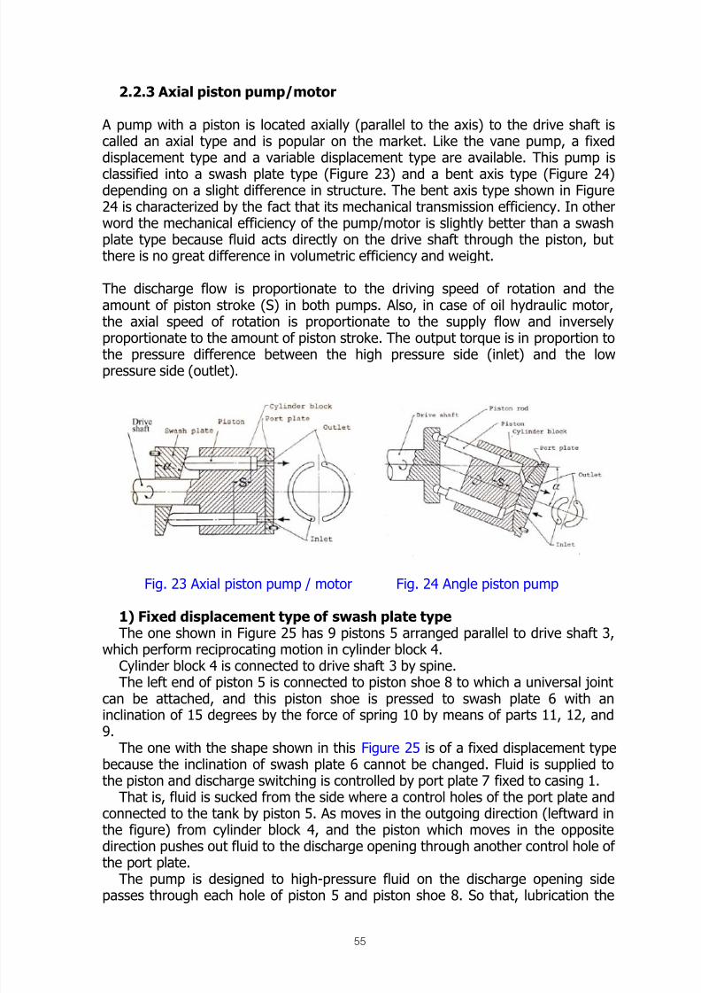
2.2.3 Axial piston pump/motor
A pump with a piston is located axially (parallel to the axis) to the drive shaft iscalled an axial type and is popular on the market. Like the vane pump, a fixeddisplacement type and a variable displacement type are available. This pump is
classified into a swash plate type (Figure 23) and a bent axis type (Figure 24)depending on a slight difference in structure. The bent axis type shown in Figure24 is characterized by the fact that its mechanical transmission efficiency. In otherword the mechanical efficiency of the pump/motor is slightly better than a swashplate type because fluid acts directly on the drive shaft through the piston, butthere is no great difference in volumetric efficiency and weight.
The discharge flow is proportionate to the driving speed of rotation and theamount of piston stroke (S) in both pumps. Also, in case of oil hydraulic motor,the axial speed of rotation is proportionate to the supply flow and inverselyproportionate to the amount of piston stroke. The output torque is in proportion tothe pressure difference between the high pressure side (inlet) and the lowpressure side (outlet).
Fig. 23 Axial piston pump / motor Fig. 24 Angle piston pump
1) Fixed displacement type of swash plate type The one shown in Figure 25 has 9 pistons 5 arranged parallel to drive shaft 3,
which perform reciprocating motion in cylinder block 4.Cylinder block 4 is connected to drive shaft 3 by spine.The left end of piston 5 is connected to piston shoe 8 to which a universal joint
can be attached, and this piston shoe is pressed to swash plate 6 with aninclination of 15 degrees by the force of spring 10 by means of parts 11, 12, and9.
The one with the shape shown in this Figure 25 is of a fixed displacement typebecause the inclination of swash plate 6 cannot be changed. Fluid is supplied tothe piston and discharge switching is controlled by port plate 7 fixed to casing 1.
That is, fluid is sucked from the side where a control holes of the port plate andconnected to the tank by piston 5. As moves in the outgoing direction (leftward inthe figure) from cylinder block 4, and the piston which moves in the oppositedirection pushes out fluid to the discharge opening through another control hole of
the port plate.The pump is designed to high-pressure fluid on the discharge opening sidepasses through each hole of piston 5 and piston shoe 8. So that, lubrication the

8/12/2019 Fishery Equipment and Hydraulic Engineer
http://slidepdf.com/reader/full/fishery-equipment-and-hydraulic-engineer 56/125
56
universal joints of these two components as well as the sliding part betweenpiston shoe 8 and swash plate 6 and also reduces contact force of this sliding part.
Fig. 25 Axial piston pump
2) Variable displacement type 1 of swash plate type
The one shown in Figure 26 is designed so that the inclination (hereafter calledangle of inclination) of swash plate 2 can be changed to the drive shaft within therange of 0 to 15 degrees by regulator 5. Consequently, the displacement volumechanges freely.
If the angle of inclination of this swash plate is zero, the swash plate isperpendicular to the piston. Since the piston stroke is zero, the displacement
volume is also zero.
Adjusting screw 6 can restrict the maximum discharge flow.
Fig. 26 Axial piston pump

8/12/2019 Fishery Equipment and Hydraulic Engineer
http://slidepdf.com/reader/full/fishery-equipment-and-hydraulic-engineer 57/125
57
2) Variable displacement type (2) of swash plate type(Figure 27 and 28)
The pump shown in Figure 27 is a combination of auxiliary pump 2,regulator 3, two relief-valves 5, and relief valve 4 for setting boost pressure
(pressure for replenishing oil for the main circuit) in one.
This type of pump differs from those described so far in the following point. Piston7 is not parallel to the drive shaft but is arranged slightly in a tapered form. If thespeed of rotation becomes high, the force maintaining contact between pistonshoe and swash plate 1 increase. In addition, contact face 8 between cylinderblock and port plate is spiracle. This contact face sticks fast without coming aparteven in a high-pressure use so that there is no leak (oil leak) from this portion,resulting in improvement in volumetric efficiency.
Also, this pump is designed for a closed circuit. The fluid is returned from theactuator back directly to this pump instead of returning to the tank and a leakfrom the actuator or the like is made up by auxiliary pump 2.
Figure 27 Variable piston pump
A and B: Main circuitG: Discharge opening or auxiliary pump
L1: Opening for replenishing fluid into thecasing
L2: Drain connection port (connection port toreturn leaked fluid into the tank)
MA: Port for measuring pressure in maincircuit A
MB: Port for measuring pressure in maincircuits B
R : Fluid removal port in the casingS : Inlet port of auxiliary pump
X1 and X2: Oil pressure inlet for controllingangle of inclination Y1 and Y2: Connection port for remote
control
Fig. 28 Main circuit

8/12/2019 Fishery Equipment and Hydraulic Engineer
http://slidepdf.com/reader/full/fishery-equipment-and-hydraulic-engineer 58/125
58
Two relief valves (with a check valve) 5 restrict the maximum pressure of maincircuits A and B and prevent overload of the driver. Office 6 is used to adjust thespeed when the angle of inclination is changed.
4) Fixed displacement type of bent axis type
The one shown in Figure 29 is an incorporation of drive shaft 2, cam plate 3,cylinder block 4, piston 5, connecting rod 6 for connecting piston and cam plate,port plate 7 and center pin 8 into housing 1.
Connecting rod 6 and center pin 8 have a universal joint to cam plate 3, andconnecting rod 6 has a universal joint to piston 5. The former and the latter are
jointed by means of pressure bar and “caulking” by rolling, respectively. Cam plate3 is perpendicular to drive shaft 2, and seven pistons 5 are inclined 25 degrees tothe drive shaft.
When the drive shaft rotates, cylinder block 4 also rotates. Piston 5 reciprocates inthe cylinder block 4 also rotates. Piston 5 reciprocates in the cylinder block. Itsucks fluid from a control hole of port plate 7 in a half-turn from the bottom deadcenter to the top dead center and discharges it from another control hole of theport plate.
Since the angle of inclination of the force applied to cylinder block 4 in thedirection becomes small by means of absorbed discharge pressure is by center pin8. Rolling of bearings installed on the periphery of the cylinder block, which arefound in ordinary pump is not necessary.
Fig. 29 Fixed displacement type of bent axis type
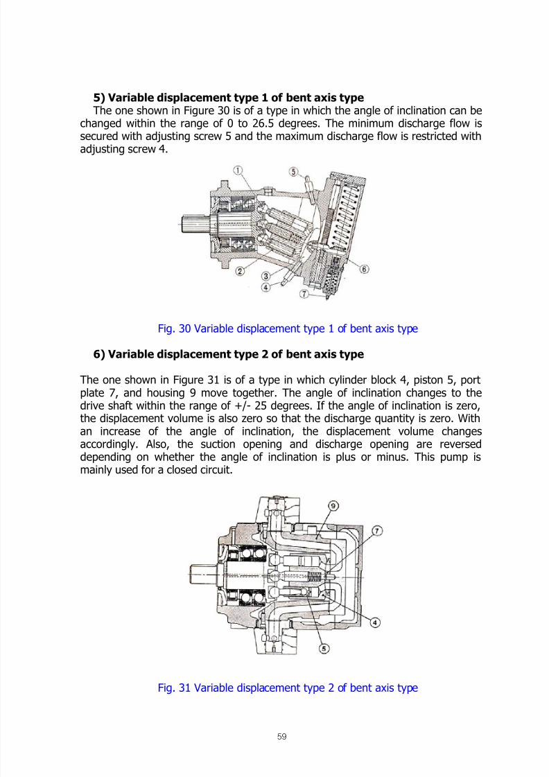
8/12/2019 Fishery Equipment and Hydraulic Engineer
http://slidepdf.com/reader/full/fishery-equipment-and-hydraulic-engineer 59/125
59
5) Variable displacement type 1 of bent axis type The one shown in Figure 30 is of a type in which the angle of inclination can be
changed within the range of 0 to 26.5 degrees. The minimum discharge flow is
secured with adjusting screw 5 and the maximum discharge flow is restricted withadjusting screw 4.
Fig. 30 Variable displacement type 1 of bent axis type
6) Variable displacement type 2 of bent axis type
The one shown in Figure 31 is of a type in which cylinder block 4, piston 5, portplate 7, and housing 9 move together. The angle of inclination changes to the
drive shaft within the range of +/- 25 degrees. If the angle of inclination is zero,the displacement volume is also zero so that the discharge quantity is zero. Withan increase of the angle of inclination, the displacement volume changesaccordingly. Also, the suction opening and discharge opening are reverseddepending on whether the angle of inclination is plus or minus. This pump ismainly used for a closed circuit.
Fig. 31 Variable displacement type 2 of bent axis type

8/12/2019 Fishery Equipment and Hydraulic Engineer
http://slidepdf.com/reader/full/fishery-equipment-and-hydraulic-engineer 60/125
60
2.3. How to control variable displacement pump and motor
There are various methods available to change the angle of inclination anddisplacement volume. These methods can be classified as shown below accordingto purpose.
1) Constant output control
This control method, which is generally called constant horse power control,constant input control, and constant P-Q control, is the most popular. Thedischarge flow Q is controlled by pressure on the discharge side of the pump P,and its relationship is expressed as P*Q = constant.
Figure 32 Relief valve diagram
In other words, the pump is controlled so that the pump output is constant, andthe output can be utilized to the full without overloading the drivers such as anelectric motor and engine.
This is used for a winch, running gears, etc. with a big load fluctuation.
2) Constant pressures hold control
Discharge flow Q equivalent to the amount required by the actuator is discharged
by pressure on the pump discharge side P so that this pressure P remainsconstant. As shown in the P-Q chart is Figure 18 (P.24), when the actuator is atrest, the pump discharge flow is almost zero discharge (called full cut off) so thatpower for driving the pump is minimized, resulting in energy-saving. The output ofthe actuator can be made constant. This is suitable for applying and holdingpressure for a long time by a cylinder, such as rubber vulcanizing press, plywoodpress, etc.
3) External plot pressure control
Pump discharge flow rate Q is controlled on the command pressure from theexternal oil hydraulic source. This has no related to the pressure on the dischargeside P. The command pressure is at the highest 40kgf /cm
2, and discharge flow Qcan be changed by changing the pressure.

8/12/2019 Fishery Equipment and Hydraulic Engineer
http://slidepdf.com/reader/full/fishery-equipment-and-hydraulic-engineer 61/125
61
4) Manual control
Discharge flow Q is controlled by turning an adjusting screw or round handle byhand.
5) Electric control
As contrasted with the manual control type mentioned above, discharge flow Q iscontrolled by turning it with a small electric motor with a reduction gear (reverserotation is possible).
6) Electromagnetic proportional control
Pump discharge flow Q is controlled in proportion to the size of external commandcurrent value. The components on the pump side receiving a command currentare an Electro-hydraulic servo valve and an proportional DC magnet.
This control method is faster in response time than the electric control mentionedabove.
7) Mechanical control
Discharge flow Q is controlled by rotating (within approx. 120 degrees), orpushing and pulling a control lever mounted on the pump.
8) Constant flow hold control
A ship has an engine as drives a pump, all construction of equipment, vehicle andthe speed of rotation is always changes.In this control method, pump discharge flow Q is automatically made constantalthough the speed of rotation changed. The horsepower required for the pumpmaintains constant even at a high speed of rotation and the actuator is notaccelerated.
This method is applied to an oil hydraulic source for driving a generator, steeringwheel, movement the ship, a concrete mixer, etc.
Precautions Handling
1. Difference between rated pressure and maximum pressure
The rated pressure is the upper limit of pressure where a continuous use ispossible. If a continuous use is done exceeding this rated pressure, theperformance described later (volumetric efficiency and mechanical efficiency)decreases and sudden damage is easily caused by generation of heat. On theother hand, the maximum pressure means that the rated pressure can be
exceeded by 1.2 to 1.5 times in a short time. However, unless as exactexplanation of this “a short time” is given (for example, 5% or less of the dutycycle time), the upper limit of the preset pressure may be generated temporarilyuntil a relief valve opens.

8/12/2019 Fishery Equipment and Hydraulic Engineer
http://slidepdf.com/reader/full/fishery-equipment-and-hydraulic-engineer 62/125
62
2. Inlet pressure limit of pump
The inlet pressure is described as –0.2 to 5 kgf /cm2. However the pressure on the
minus side, as is called a negative pressure, is lower than the atmosphericpressure, which is the limit against cavitations. On the other hand, the pressure on
the plus side, if it is 1 kgf /cm2 or less, is determined based on the long-timewithstand pressure of built-in oil seal. If this pressure is 1 kg f /cm
2 or more, thepump has such a structure that a suction opening and oil seal is not directlyconnected, and the plus side pressure is determined according to the strength ofother components.
When the pump sucks in fluid, if suction conditions are bad, the pump cannotnormally suck it in, causing a cavity in fluid.This is called cavitations. As a result, the pump causes abnormal noise. The causesof cavitations are as follows:
1)
A filter (strainer) on the suction side is clogged, a filter is too small, or afiltering accuracy is too high (the mesh is too fine).
2) An inlet pipe is too long, it has too many bends, or it is too thin.
3) A wrong fluid is chosen, or viscosity of fluid becomes high due to a decrease inoil temperature.
4) The pump is installed at a position to high from the oil level in the oil tank(installation position).
5) The pump is driven at the specified maximum speed of rotation or higher.
6) An air breather (Entrance/exit of air at the top of the tank. Provided with an airfilter) is too small, or a built-in air filter is clogged.
3. Range of working speed of rotation
The limit of the minimum speed of rotation is determined, considering thefollowing matters.
1) The decrease in volumetric efficiency exceeding the limit must not lead todamage of internal parts caused by abnormal generation of heat.
2) A poor total efficiency must not cause any problem as a matter of practicality.
3) In case of an oil hydraulic motor, non-uniform rotation easily occurs on theoutput shaft, but its limit must not be exceeded.
The limit of the maximum speed of rotation is determined, considering the
following matters.
1) In case of a pump, no cavitations must occur.

8/12/2019 Fishery Equipment and Hydraulic Engineer
http://slidepdf.com/reader/full/fishery-equipment-and-hydraulic-engineer 63/125

8/12/2019 Fishery Equipment and Hydraulic Engineer
http://slidepdf.com/reader/full/fishery-equipment-and-hydraulic-engineer 64/125
64
If the pump is rotated reversibly, the suction opening and discharge opening arereversed. For this reason, pay attentions to the rotation direction clearly are twotypes of pump, right-handed and left-handed rotation. Also, a bi-directional type isavailable for the oil hydraulic motor. Therefore, there are total three differenttypes. Although there is little difference in appearance, the internal parts areslightly different from each other. Note that they cannot be replaced with each
other.
8. Procedure of drain piping
Unless internal leaks oil in the gear motor, vane pump/motor, piston pump/motorexcept the gear pump is let escape into the tank, the built-in oil seal is damaged.The piping for this purpose is called the drain piping.
Only the gear pump let this internal leak oil escape to the suction opening in thepump itself so that the external drain piping is not necessary.
Internal leak oil is indispensable because it serves for both lubrication and coolingof pump/motor bearings, but too much internal leak oil causes a decrease intransmission power. From the above-mentioned, the drain piping must be doneaccording to the following procedure.
1) Use the highest drainpipe opening and fill the main unit with internal leak oil.In case there is only one drain pipe mouth and it comes to the bottom, arrangethe drain pipe higher than the top position of the main unit once, then connectit to the tank so that oil in the main unit does not escape.
2)
The long-time withstand pressure of a built-in oil seal is described in thecatalog specification which is generally about 1 kgf /cm2. For this reason, it is
necessary to hold down the passing resistance of the drain pipe to thiswithstand pressure or lower, and attention must be paid to the thickness andlength of the pipe, and number of bends. Furthermore, connect the drainpipeto the tank singly. Do not join it to a return pipe through which a large amountof oil passes.
3) Before performing a trial run or replacing a pump/an oil hydraulic motor, pourfluid from the drain port, arrange the drain pipe, then put the pump/oilhydraulic motor into operation.
9. How to see the performance table and efficiency
Judge whether the performance is food or poor by seeing the following threetypes of efficiency.

8/12/2019 Fishery Equipment and Hydraulic Engineer
http://slidepdf.com/reader/full/fishery-equipment-and-hydraulic-engineer 65/125
65
1) Volumetric efficiency
Generally, efficiency is expressed with η and a subscript indicates what efficiencyit is. Volumetric efficiency is described as ηv and is obtained from the followingequation, which shows a condition of the internal leak of the pump/motor.
(Note) Make an arrangement so that the speed of rotation is always constant ormake compensation by means of a calculation so that it is always constant.
If the volumetric efficiency of the pump is 90%, in reality it discharges only 90l/min even if it sucks in 100 l/min.
The remaining 10 l/min is returned to the tank with the drainpipe as an internalleak. If the volumetric efficiency of the oil hydraulic motor is 90%, only 90 l/min isused for rotating the oil hydraulic motor even if 100 l/min is flowed in so that thespeed of rotation decreases by 10%.
The higher the pressure is, the more the internal leak is. The higher the oiltemperature is, the more the internal leak is. As a result, the volumetric efficiency
decreases. Also, the internal leak flow does not change so much if the workingpressure and oil temperatures are determined. Therefore, if the pump/motorrotates at a low speed, the “discharge (outlet) flow at a very low pressure withoutinternal leak” becomes small, and a proportion with the internal leak flow becomeshigh. As a result, the internal leak flow becomes high. As a result the volumetricefficiency decreases.
2) Mechanical efficiency (also called torque efficiency)
It is described as ηt. Transmission torque decreases due to a rolling resistance orsliding resistance of pump/motor bearings. The mechanical efficiency represents
this decrease rate. The transmission efficiency of a reduction gear or the likecorresponds to this.
Torque on the axial side T1 is measured with a torque meter, and torque on theoil pressure side of a pump/motor T2 is obtained from the following equation. Theproportion of these values is mechanical efficiency.
Where, P1 = Inlet pressure (kgf /cm2)
P2 = Outlet pressure (kgf /cm2)
q = Displacement (cc/rev)
Volumetric efficiency
of oil hydraulic motor
Outlet flow at a very low pressure withoutinternal leak
Outlet flow at a measured pressure +External drain flow rate
=x 100 (%)
Volumetric efficiency
of pump
Discharge flow rate at the measuredpressure with internal leak
Inlet flow rate at suction side +External drain flow rate
=x 100 (%)
T2
(P1 – P2) x q
200π= 100 (%)x
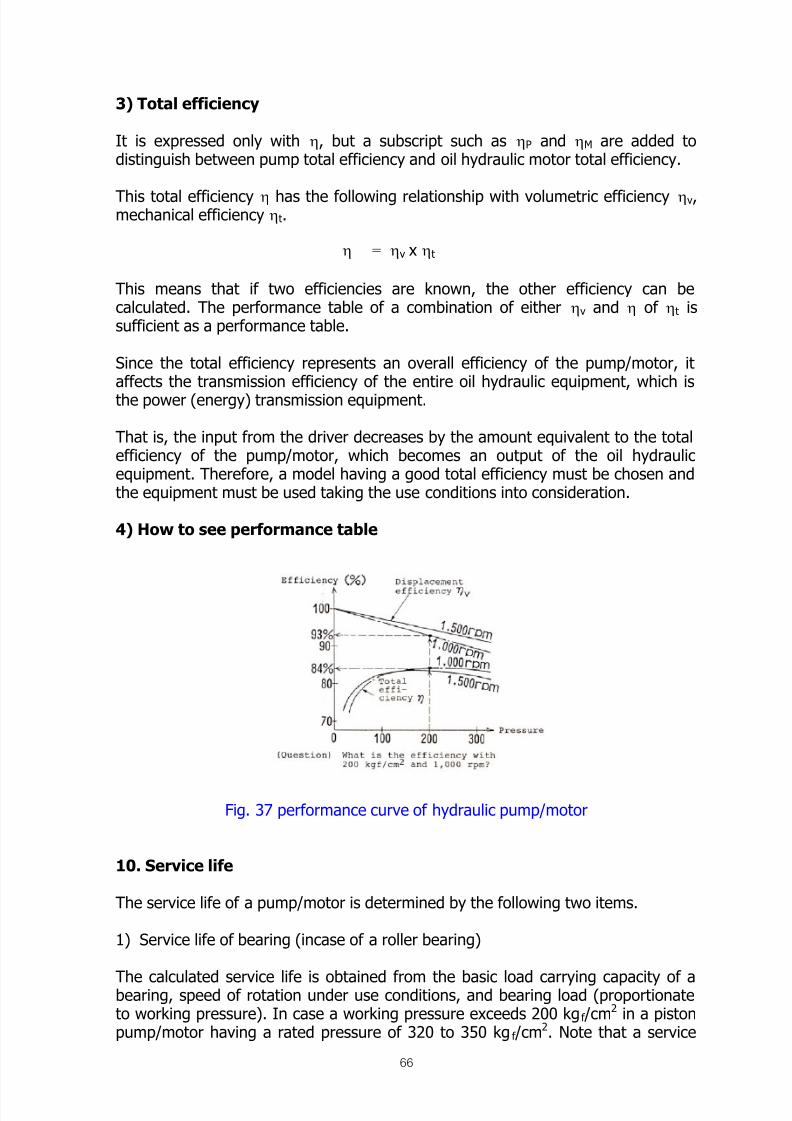
8/12/2019 Fishery Equipment and Hydraulic Engineer
http://slidepdf.com/reader/full/fishery-equipment-and-hydraulic-engineer 66/125
66
3) Total efficiency
It is expressed only with η, but a subscript such as ηP and ηM are added todistinguish between pump total efficiency and oil hydraulic motor total efficiency.
This total efficiency η has the following relationship with volumetric efficiency ηv,mechanical efficiency ηt.
This means that if two efficiencies are known, the other efficiency can becalculated. The performance table of a combination of either ηv and η of ηt issufficient as a performance table.
Since the total efficiency represents an overall efficiency of the pump/motor, itaffects the transmission efficiency of the entire oil hydraulic equipment, which isthe power (energy) transmission equipment.
That is, the input from the driver decreases by the amount equivalent to the totalefficiency of the pump/motor, which becomes an output of the oil hydraulicequipment. Therefore, a model having a good total efficiency must be chosen andthe equipment must be used taking the use conditions into consideration.
4) How to see performance table
Fig. 37 performance curve of hydraulic pump/motor
10. Service life
The service life of a pump/motor is determined by the following two items.
1) Service life of bearing (incase of a roller bearing)
The calculated service life is obtained from the basic load carrying capacity of abearing, speed of rotation under use conditions, and bearing load (proportionateto working pressure). In case a working pressure exceeds 200 kgf /cm
2 in a pistonpump/motor having a rated pressure of 320 to 350 kgf /cm
2. Note that a service
η ηv x ηt=
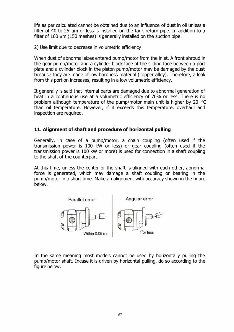
8/12/2019 Fishery Equipment and Hydraulic Engineer
http://slidepdf.com/reader/full/fishery-equipment-and-hydraulic-engineer 67/125
67
life as per calculated cannot be obtained due to an influence of dust in oil unless afilter of 40 to 25 μm or less is installed on the tank return pipe. In addition to afilter of 100 μm (150 meshes) is generally installed on the suction pipe.
2) Use limit due to decrease in volumetric efficiency
When dust of abnormal sizes entered pump/motor from the inlet. A front shroud inthe gear pump/motor and a cylinder block face of the sliding face between a portplate and a cylinder block in the piston pump/motor may be damaged by the dustbecause they are made of low hardness material (copper alloy). Therefore, a leakfrom this portion increases, resulting in a low volumetric efficiency.
It generally is said that internal parts are damaged due to abnormal generation ofheat in a continuous use at a volumetric efficiency of 70% or less. There is noproblem although temperature of the pump/motor main unit is higher by 20 °Cthan oil temperature. However, if it exceeds this temperature, overhaul andinspection are required.
11. Alignment of shaft and procedure of horizontal pulling
Generally, in case of a pump/motor, a chain coupling (often used if thetransmission power is 100 kW or less) or gear coupling (often used if thetransmission power is 100 kW or more) is used for connection in a shaft couplingto the shaft of the counterpart.
At this time, unless the center of the shaft is aligned with each other, abnormal
force is generated, which may damage a shaft coupling or bearing in thepump/motor in a short time. Make an alignment with accuracy shown in the figurebelow.
In the same meaning most models cannot be used by horizontally pulling thepump/motor shaft. Incase it is driven by horizontal pulling, do so according to thefigure below.

8/12/2019 Fishery Equipment and Hydraulic Engineer
http://slidepdf.com/reader/full/fishery-equipment-and-hydraulic-engineer 68/125
68
Fig. 38 Alignment of shaft and pulley
12. Starting torque of oil hydraulic motor
When the oil hydraulic motor is started, a starting torque is required to overcomea static friction resistance. After it is started, it can be driven at a torque lowerthan the starting torque due to a dynamic friction resistance. For this reason,when a full load is imposed at the start of the oil hydraulic motor, it cannot bestarted unless the starting torque is taken into consideration. The starting torqueis calculated from the starting torque efficiency.
13. Using oil hydraulic motor at a low speed of rotation and reductiongear
When the oil hydraulic motor is used at a low speed of rotation, its efficiencydecreases an non-uniform rotation (called stick slip) occurs. For this reason, installa reduction gear, if necessary. Types and features of reduction gears commerciallyavailable and generally used are described below.
Table 8
Type \ Features Reduction ratioTransmission
efficiencyPrice
Spur gear type
(Single)
1/3 ~ 1/5 90 ~ 92% Low
Spur gear type
(Double)
1/9 ~ 1/25 85% Medium
Planetary type 1/6 ~ 1/30 96% High
Note: Usually, a planetary reduction gear is used because a double spurs geartype. Reduction gear is poor in transmission efficiency.

8/12/2019 Fishery Equipment and Hydraulic Engineer
http://slidepdf.com/reader/full/fishery-equipment-and-hydraulic-engineer 69/125
69
14. Countermeasures against negative load of oil hydraulic motor(Measures against runaway)
When a negative loads is imposed on an oil hydraulic motor. (in case an oilhydraulic motor is rotated by self-weight of load) a counterbalance valve (backpressure valve) must be installed on the tank return side as shown in the figure
below.
Thus, a runaway rotation of an oil hydraulic motor can be prevented.
15. Basic calculation equation (related to the pump)
1) Actual discharge
Where, q P : Displacement (cc/rev)N P : Number of revolution (rpm)ηv : Volumetric efficiencyηP : Pump total efficiency
16. Basic calculation equation (related to the oil hydraulic motor) 1) Required flow
2) Output torque
3)
Output
Q q P x N P x ηv
1000= l / min
Qoq O x N O
1000 ηv
= l / min
TO
(P1 – P2) x q O x ηt
200π= (kgf-m)
LO
N O x T O
975= (kW)

8/12/2019 Fishery Equipment and Hydraulic Engineer
http://slidepdf.com/reader/full/fishery-equipment-and-hydraulic-engineer 70/125

8/12/2019 Fishery Equipment and Hydraulic Engineer
http://slidepdf.com/reader/full/fishery-equipment-and-hydraulic-engineer 71/125

8/12/2019 Fishery Equipment and Hydraulic Engineer
http://slidepdf.com/reader/full/fishery-equipment-and-hydraulic-engineer 72/125
72
2.4.3. Radial piston motor (star motor)
If the oil hydraulic motors described so far are used at 800 to 1,500 rpm, it is aneffective use. On the other hand, the radial motor (star motor) shown in Figure 36 is used at a low speed of rotation of 10 to 200 rpm and a large type is available sothat a large output torque can be obtained. The radial motor is used for a low-
speed rotation driver such as an axle of a bogie and construction vehicle, winchdrum, truck mixer agitator, etc.
Fig. 36 Radial piston motor (Star motor)
2.4.4. Cylinder and rotary motor
The cylinder is the oil hydraulic equipment to convert fluid energy sent by thepump into mechanical energy, and performs rectilinear motion such as pulling andpushing.
Output (F) of the cylinder is obtained from a product of load pressure (P) andpressure receiving area of cylinder (A).
This output (F) is constant from the starting point of a stroke to the end point.
Velocity of cylinder motion (V) is determined by inflow of fluid within a certain unittime and pressure receiving area of the cylinder (A).
F P x A =
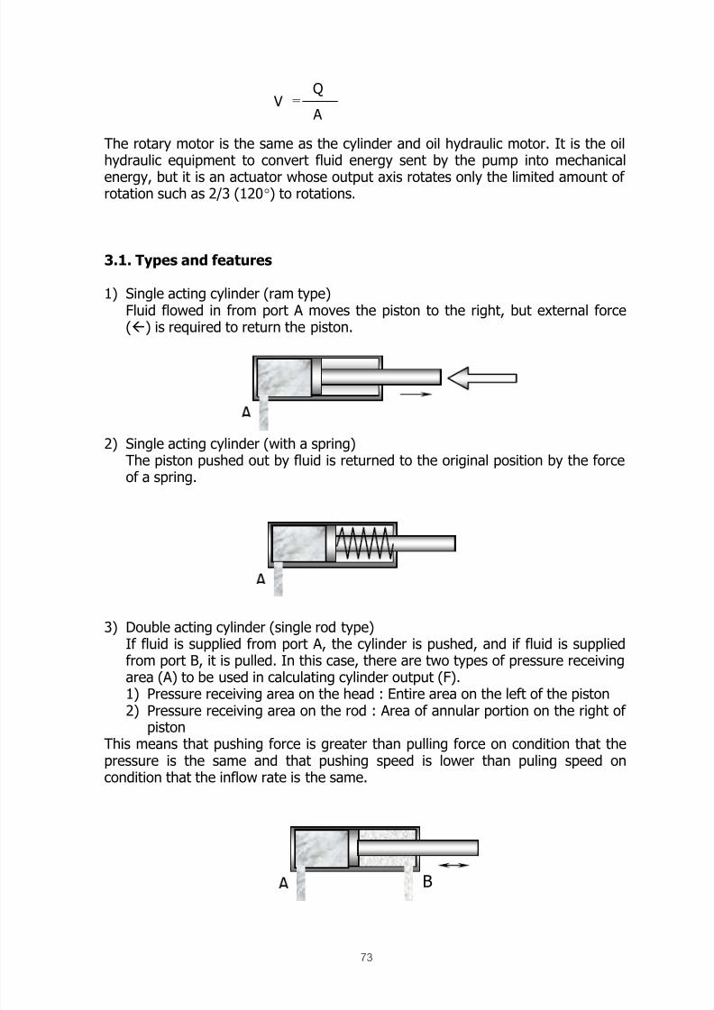
8/12/2019 Fishery Equipment and Hydraulic Engineer
http://slidepdf.com/reader/full/fishery-equipment-and-hydraulic-engineer 73/125
73
The rotary motor is the same as the cylinder and oil hydraulic motor. It is the oilhydraulic equipment to convert fluid energy sent by the pump into mechanical
energy, but it is an actuator whose output axis rotates only the limited amount ofrotation such as 2/3 (120°) to rotations.
3.1. Types and features
1) Single acting cylinder (ram type)Fluid flowed in from port A moves the piston to the right, but external force() is required to return the piston.
2) Single acting cylinder (with a spring)The piston pushed out by fluid is returned to the original position by the forceof a spring.
3) Double acting cylinder (single rod type)If fluid is supplied from port A, the cylinder is pushed, and if fluid is suppliedfrom port B, it is pulled. In this case, there are two types of pressure receivingarea (A) to be used in calculating cylinder output (F).1) Pressure receiving area on the head : Entire area on the left of the piston
2)
Pressure receiving area on the rod : Area of annular portion on the right ofpiston
This means that pushing force is greater than pulling force on condition that thepressure is the same and that pushing speed is lower than puling speed oncondition that the inflow rate is the same.
VQ
= A
B
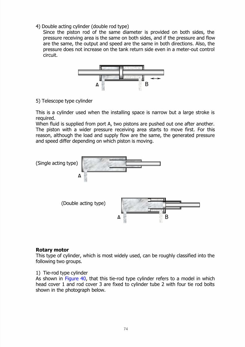
8/12/2019 Fishery Equipment and Hydraulic Engineer
http://slidepdf.com/reader/full/fishery-equipment-and-hydraulic-engineer 74/125
74
4) Double acting cylinder (double rod type)Since the piston rod of the same diameter is provided on both sides, thepressure receiving area is the same on both sides, and if the pressure and floware the same, the output and speed are the same in both directions. Also, thepressure does not increase on the tank return side even in a meter-out controlcircuit.
5) Telescope type cylinder
This is a cylinder used when the installing space is narrow but a large stroke isrequired.When fluid is supplied from port A, two pistons are pushed out one after another.The piston with a wider pressure receiving area starts to move first. For thisreason, although the load and supply flow are the same, the generated pressureand speed differ depending on which piston is moving.
Rotary motorThis type of cylinder, which is most widely used, can be roughly classified into thefollowing two groups.
1) Tie-rod type cylinder As shown in Figure 40, that this tie-rod type cylinder refers to a model in whichhead cover 1 and rod cover 3 are fixed to cylinder tube 2 with four tie rod boltsshown in the photograph below.
(Single acting type)
(Double acting type)
B
B
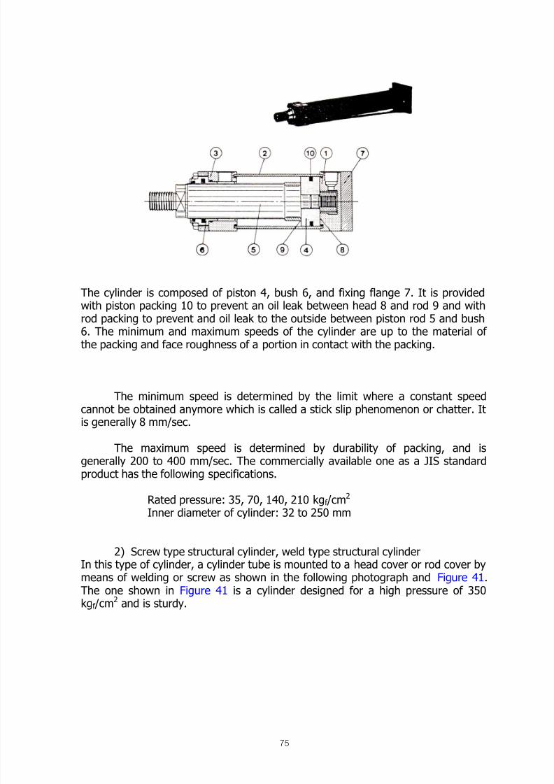
8/12/2019 Fishery Equipment and Hydraulic Engineer
http://slidepdf.com/reader/full/fishery-equipment-and-hydraulic-engineer 75/125
75
Fig. 40 Tie-rod type cylinder
The cylinder is composed of piston 4, bush 6, and fixing flange 7. It is providedwith piston packing 10 to prevent an oil leak between head 8 and rod 9 and withrod packing to prevent and oil leak to the outside between piston rod 5 and bush6. The minimum and maximum speeds of the cylinder are up to the material ofthe packing and face roughness of a portion in contact with the packing.
The minimum speed is determined by the limit where a constant speed
cannot be obtained anymore which is called a stick slip phenomenon or chatter. Itis generally 8 mm/sec.
The maximum speed is determined by durability of packing, and isgenerally 200 to 400 mm/sec. The commercially available one as a JIS standardproduct has the following specifications.
Rated pressure: 35, 70, 140, 210 kgf /cm2
Inner diameter of cylinder: 32 to 250 mm
2)
Screw type structural cylinder, weld type structural cylinderIn this type of cylinder, a cylinder tube is mounted to a head cover or rod cover bymeans of welding or screw as shown in the following photograph and Figure 41.The one shown in Figure 41 is a cylinder designed for a high pressure of 350kgf /cm
2 and is sturdy.

8/12/2019 Fishery Equipment and Hydraulic Engineer
http://slidepdf.com/reader/full/fishery-equipment-and-hydraulic-engineer 76/125
76
Fig. 41 Screw type structural cylinder
Rotary motor
Fig. 51 Rotary motor
Spool 2 mounted on the piston moves right and left by the force of fluid. The rackmounted on spool 2 rotates pinion gear 3 and rotates the output shaft within acertain speed of rotation. The torque of the output shaft is determined in
proportion to a working pressure, and the rotational speed is determined by asupplied flow. The piston stroke is limited by adjusting screw 4, and the number ofrevolutions of the output shaft is determined.

8/12/2019 Fishery Equipment and Hydraulic Engineer
http://slidepdf.com/reader/full/fishery-equipment-and-hydraulic-engineer 77/125
77
This is used to open/close a large-size door or a marine hatches cover, which areusually used at rotation of 360 degrees or less. The product shown in thephotograph is used at a rocking angle of 180 degrees, maximum torque of 2,600kgf .m, and rated pressure of 160 kgf /cm
2.
Precautions in handling cylinder
1. Model of rod
Among the JIS conforming articles, two types of piston rod, standard type (alsocalled type C) and strong type (also called type B) which is slightly thicker, areavailable on the market? The strong type has the following features, compared tothe standard type.1) The buckling strength increases because of a thick rod.2) The pulling speed is easily increased because the pressure receiving area on
the rod side decreases.3) The output (pulling side) decreases because the pressure receiving area on the
rod side decreases.
2. Restriction on maximum stroke Considering the bucking strength of the rod, the rod can be prolonged in case of alow load or in case of a high load by pulling.However, note that manufacturer as shown in Table below restricts the maximumstroke of a standard article.
Inner diameter of cylinder (mm) 40.50 63.80 100~250
Maximum stroke (mm) 1,200 1,600 2,000
3. Position of port, cushioning mechanism, and air bleeder Sufficient workspace is necessary to perform the piping of ports, adjustment ofcushioning mechanism, and air bleeding. Note that the model indication of JISconforming articles has a specification of these positions (4 directional positions oftop bottom left and right).
4. Minimum working pressure and performance (efficiency) In the JIS conforming cylinders, the upper limit of pressure at which the cylinder isactuated by a pressure from the head is specified by the shape of a packing and
the nominal pressure, and it is approximately 2 kg f /cm
2
for general productavailable on the market. This is the minimum working pressure, and the cylindershould be actuated at this pressure or lower.
The static friction resistance of a piston packing and rod packing corresponds tothis pressure. Since it changes to the dynamic friction resistance after start-up, theminimum working pressure decreases to 0.2 to 0.3 kgf /cm
2.
However, the mechanical efficiency of the cylinder is considered to be 100% as amatter of practicality because these pressures are very low compared to theworking pressure. Volumetric efficiency ηv is 100% because there is no leak from
a piston packing or rod packing.

8/12/2019 Fishery Equipment and Hydraulic Engineer
http://slidepdf.com/reader/full/fishery-equipment-and-hydraulic-engineer 78/125
78
5. Upper and lower limit of speed The minimum and maximum speeds are specified for the JIS conforming cylinders.For example. 8 to 400 mm/sec for the inner diameter of the cylinder of 32 to 63mm. 8 to 300 mm/sec for that of 80 of to 125. 8 to 200 mm/sec for that of 140 to250 mm. If both limits are exceeded, a cylinder is made to order because theshape, material, etc. of a packing must be changed. The maximum speed has
such a problem that cylinder speed is “not uniform” (called stick slip) and what isknown as “chatter” occurs.
6. Air bleeding
Air in the cylinder should be bleeder with an air vent valve provided on both rodand head sides at a trial run after installation. Otherwise, “inconsistencies” incylinder motion may occur in proportion to the remaining quantity of air.
7. Protective measures for piston rod Rust and flaws on the rod may damage a rod packing and cause an external oilleak. Take the following points into consideration as countermeasures against rust.1) The rod end which is pulled in should be used for a longer time, and it should
be exposed to air for a time as short as possible.2) Material should be changed to stainless or the rod should be plated to take
countermeasures against water, seawater, etc. To prevent flaws, the followingmeasures are taken.1) Application of bellows (Figure 52)
Figure 52 Protection of piston rod
2) If there is some problem in strength of bellows, make a protective coverwith an iron plate or the like.

8/12/2019 Fishery Equipment and Hydraulic Engineer
http://slidepdf.com/reader/full/fishery-equipment-and-hydraulic-engineer 79/125
79
Valve
A valve is installed at an intermediate position between an actuator and a pump tocontrol the magnitude of output, the direction of output, or the speed of output ofthe actuator or to control so that the pump makes no-load drive.
Type of valve1) Classification according to the purposes of control
2) Valves classified according to the shapeStacked valveMultiple control valve
3) Valves classified by the method of control
Remote control valve (direct operated relief valve), solenoid proportional valve,and serve valve.
4) Element valves to combine multifunctional combination valves logic valve(cartridge type two way valves)
5) Valves included in accessoryStop valve (butterfly valve, gate valve), gage cock, pressure switch.
Pressure control valve
1) Relief valve (Safety valve) Valve perceives the inlet pressure (A port). When pressure rise over a setpressure, the needle of valve moved up to decrease the hydraulic oil in highpressure back to tank (B port) as preventing the exceeding set-pressure.
Pressure control valve
Directional control valve
Flow control valve
Relief valve (safety valve) [direct operated type and
balanced piston type]
Reducing valve [ dito]
Sequence valve Sequence valve [ dito]
Counterbalance valve [ dito]
Unloading valve [direction operated
type and balanced piston type]
Unloading relief valve
Brake valve
Check valve Check valve
Pilot operated check valve
Prefill valve
Shuttle valve
Directional control valve Hand operated valve
Solenoid valve
Pilot operated valve with solenoid control
Pilot operated directional valve
Throttle check valve
Flow control valve
Deceleration valve
Flow dividing valve

8/12/2019 Fishery Equipment and Hydraulic Engineer
http://slidepdf.com/reader/full/fishery-equipment-and-hydraulic-engineer 80/125
80
In other words, this valve limits the upper limit of the pressure. When the pressureat the entrance becomes below the set pressure, the valve is closed.
Where this valve is used to control the output of an actuator, this valve is called arelief valve. Where this valve is used to prevent oil hydraulic units from damaging
and is not opened except emergency, this valve is called a safety valve. The nameof the valve changes depending upon its application.
When the valve is opened, the hydraulic oil (flow Q L/min) drops its pressure froma set pressure (P kgf /cm
2) to 0 kgf /cm2. At this time, the pressure energy, which
has been lost changes to thermal energy, which raise the oil temperature.
When the actuator has stopped, the delivery flow from the pump passes throughthis valve, and the output of the drive machine is all used for heating (in the caseof a fixed delivery pump). The opening of the valve seat part changes dependingupon the flow which passes there. As the flow is increased, the pressure at the A-port becomes higher somewhat.
Over-ride pressure characteristics represent this condition. The valves where thepressure at the A-port is as close to the cracking pressure as possible when thepassing flow is increased may be called good valves.
1) Direct operated type relief valveFig. 58 indicates the basic diagram of this valve. A needle valve 5 is pressed
against a valve seat 6 by a spring 3. The spring chamber is led to a tank (B port).Further, a pressure is introduced in the valve seat part from the A port to push upthe needle valve 5 against the spring 3. Since the repulsion of the spring 3 can beadjusted freely by an adjustment screw 4, the pressure from the A port can be setat any point observing a pressure gauge.
Fig. 58 Diagram of relief valve Fig. 59 Structure of relief valve
Calorific value =Q x P
612x 860 Kcal / hr

8/12/2019 Fishery Equipment and Hydraulic Engineer
http://slidepdf.com/reader/full/fishery-equipment-and-hydraulic-engineer 81/125
81
An actual construction drawing is shown in Fig. 59. A cushion (damper) 7 isattached to the needle valve 5 to absorb the vibrations of the needle valve when itis opened.This valve is a direct operated type relief valve of a cartridge manifold block, etc.The bottom surface of the spring receiving part of the needle valve is actuated sothat the valve seat part can be farther opened receiving the impulse force of the
hydraulic oil when the valve is opened. Thus, the override pressure characteristicscan be held better.
2) Balanced piston type relief valveThis valve has the following features when compared with the direct operated typevalves:
1) Better override pressure characteristics.2) Small and lightweight for large capacity valves.3) Good stability for occurrence of chattering, tramp, etc. of valve.
For these reasons, this balanced piston type relief valve is mostly used except thecases where impact loading is applied or where used at a small flow below10L/min.
Fig. 60 Balance piston type of relief valve
Fig. 60 shows the basic diagram of this valve, and the reference numeral 1designates the direct operated relief valve described above. The pressure of the A-port acts on the bottom side of a main valve 2 and on the upper side of the main
valve 2 and the needle valve part of the direct operated type relief valve throughan orifice 3.
When the needle valve is not opened, the pressure balance is held. As shown inthe figure, the main valve 2 is located at the starting position by the spring 4, andthe A-port is separated from the B port by the valve seat part 5.
When the pressure in the A-port has increased and the direct operated type reliefvalve is opened, the hydraulic oil flows to the tank (B port) through the orifice 3,the needle valve, and the central hole of the main valve 2.
At this time, a pressure drop occurs in the orifice 3, the pressure balance betweenthe upper surface and the bottom surface of main valve 2 is broken. The mainvalve 2 moves upward against the spring 4 to open the valve seat part 5, and the

8/12/2019 Fishery Equipment and Hydraulic Engineer
http://slidepdf.com/reader/full/fishery-equipment-and-hydraulic-engineer 82/125
82
hydraulic oil escapes to the tank through the A-port and The B-port so that thepressure in the A port do not exceed the set pressure.
As the pressure in the A-port is lowering, the needle valve part is closed, and themain valve 2 is pushed down by the force of the spring 4 to close the valve seatpart 5.
Fig. 61 structure of balance type of relief valve
Fig. 61, the flange type, shows the actual internal construction of the basicdiagram (Fig. 60).
Fig. 62, the gasket type, shows a balanced piston type relief valves although theinternal construction is different a little.
The pressure in the A port in Fig. 62 acts on the upper part (the chamber wherethe spring 4 exists) of the main valve through orifices (3.1), (3.2), the valve seatpart of the needle valve (1), and the orifice (3.3).
The orifice (3.3) acts as a cushion to prevent the main valve from vibrating. The
filter 6 prevents clogging of the orifice (3.2) due to large dust. In this valve, thehydraulic oil flowing after the needle valve has opened is connected with the Bport (the internal drain system). Where a back-pressure is expected to occur inthe B port, it is possible to switch to the external drain system.

8/12/2019 Fishery Equipment and Hydraulic Engineer
http://slidepdf.com/reader/full/fishery-equipment-and-hydraulic-engineer 83/125
83
The valve shown in Fig. 63 is a relief valve having an unload solenoid valve 3fitted. The solenoid valve is connected immediately before the valve seat part ofthe needle valve. Even when the needle valve part is closed, the solenoid valve isexcited. If the hydraulic oil flows into the solenoid valve, the upper part of themain valve becomes atmospheric pressure. As a result, the pressure in the A portbecomes a low pressure to resist the spring of main valve having force of about 3kgf /cm
2, and the hydraulic oil flows from the A-port to the B-port to become anunload condition.
The attached solenoid valve 3 includes a type, which opens to connect with the Bport when excited, and a type, which is closed when excited. This valve is usedwhere a pump is started under no load or where the loss of power is minimized
while the machine is stopped. The valve shown in Fig. 64 is used for the samepurpose as Fig. 63. The solenoid valve 3 is connected with the bent connectionport (X port) of a flange type relief valve through external piping.
Fig. 64 Started under no load of relief valve with solenoid
Fig. 63 Relief valve with unloadsolenoid valve
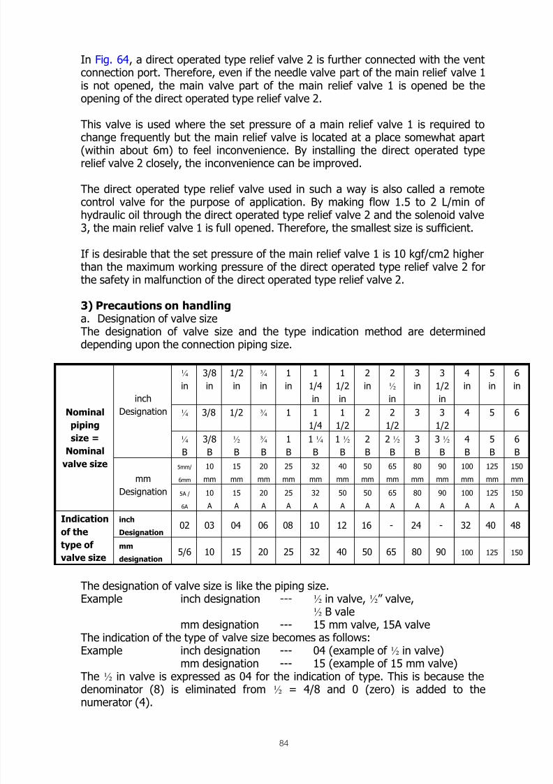
8/12/2019 Fishery Equipment and Hydraulic Engineer
http://slidepdf.com/reader/full/fishery-equipment-and-hydraulic-engineer 84/125
84
In Fig. 64, a direct operated type relief valve 2 is further connected with the ventconnection port. Therefore, even if the needle valve part of the main relief valve 1is not opened, the main valve part of the main relief valve 1 is opened be theopening of the direct operated type relief valve 2.
This valve is used where the set pressure of a main relief valve 1 is required to
change frequently but the main relief valve is located at a place somewhat apart(within about 6m) to feel inconvenience. By installing the direct operated typerelief valve 2 closely, the inconvenience can be improved.
The direct operated type relief valve used in such a way is also called a remotecontrol valve for the purpose of application. By making flow 1.5 to 2 L/min ofhydraulic oil through the direct operated type relief valve 2 and the solenoid valve3, the main relief valve 1 is full opened. Therefore, the smallest size is sufficient.
If is desirable that the set pressure of the main relief valve 1 is 10 kgf/cm2 higherthan the maximum working pressure of the direct operated type relief valve 2 forthe safety in malfunction of the direct operated type relief valve 2.
3) Precautions on handling a. Designation of valve sizeThe designation of valve size and the type indication method are determineddepending upon the connection piping size.
¼
in
3/8
in
1/2
in
¾
in
1
in
1
1/4
in
1
1/2
in
2
in
2
½
in
3
in
3
1/2
in
4
in
5
in
6
in
¼ 3/8 1/2 ¾ 1 11/4
11/2
2 21/2
3 31/2
4 5 6
inch
Designation
¼
B
3/8
B
½
B
¾
B
1
B
1 ¼
B
1 ½
B
2
B
2 ½
B
3
B
3 ½
B
4
B
5
B
6
B
5mm/
6mm
10
mm
15
mm
20
mm
25
mm
32
mm
40
mm
50
mm
65
mm
80
mm
90
mm
100
mm
125
mm
150
mm
Nominalpiping
size =
Nominal
valve size
mm
Designation 5A /
6A
10
A
15
A
20
A
25
A
32
A
50
A
50
A
65
A
80
A
90
A
100
A
125
A
150
A
inch
Designation 02 03 04 06 08 10 12 16 - 24 - 32 40 48
Indication
of the
type ofvalve sizemmdesignation 5/6 10 15 20 25 32 40 50 65 80 90 100 125 150
The designation of valve size is like the piping size.Example inch designation --- ½ in valve, ½” valve,
½ B valemm designation --- 15 mm valve, 15A valve
The indication of the type of valve size becomes as follows:Example inch designation --- 04 (example of ½ in valve)
mm designation --- 15 (example of 15 mm valve)The ½ in valve is expressed as 04 for the indication of type. This is because the
denominator (8) is eliminated from ½ = 4/8 and 0 (zero) is added to thenumerator (4).

8/12/2019 Fishery Equipment and Hydraulic Engineer
http://slidepdf.com/reader/full/fishery-equipment-and-hydraulic-engineer 85/125
85
In future, the designation will be united to the mm designation. At present, themm designation is used half-and-half as can seen in our catalogue.
b. Allowable back pressureOf course, the over-ride pressure characteristic becomes worse by the backpressure generated. From the viewpoint of the valve safety, the back pressure
must be low as much as possible.In the catalogue, the values of allowable back pressure are indicated from thestrength, so care should be taken.
c. Minimum set pressureIn the case of the balanced piston type, an oil pressure to overcome the forceof the spring at the main valve is necessary, so the minimum set pressure cannot become zero. In the test run adjustment, care should be taken so that thecylinder does not move due to this pressure (residual pressure).
d. Maximum set pressureIn the case of the balanced piston type, the spring of the direct operated typerelief valve, which has been incorporated, includes 2 to 4 types, so themaximum pressure which can be set is different according to the type ofsprings.
Existence of one spring having the strongest spring force may be sufficient, butthe fine adjustments when low pressures are set becomes difficult, and theover-ride pressure characteristics becomes worse.
e. Flow rateThe rated of flow shown in the catalogue includes two types of expression, so
the size of valve should be determined taking full care about.There two types; to determine according to the piping size to be connected,and to determine from the critical flow which can ensure the functions of thevalve. The farmer is determined from the flow speed in the pipe (3 to 4 m/sec),and the latter is an experimental value which is obtained only from the primaryfunctions of the valve without considering the over-ride pressure characteristicsand the piping resistance of the whole oil hydraulic circuit.Of course, the latter is expressed as a larger flow, and the connection pipingshould be increased using reducers. Care should be taken that both of them aredescribed in our catalogue.
f. Connection methodThere are three types of connection methods as shown in Fig. 65. In the flangetype, the valve can be suspended on the way of piping, and the valve body canbe removed by removing the bolts in the flange part.The gasket type is convenient to install on a manifold block. When installedseparately, it can be mounted on a sub-plate.The thread type can be suspended on the way of piping. The valve body hastapered screws, so the number of parts is small. However, with respect to thethread type, it should be noted that the tapered thread part requires a sealtape, that the tapered screw should not be tightened too much (from the
viewpoint of strength), and that it is difficult to remove from the piping.

8/12/2019 Fishery Equipment and Hydraulic Engineer
http://slidepdf.com/reader/full/fishery-equipment-and-hydraulic-engineer 86/125
86
Fig. 65 Three types of connection methods.
g. High vent type As shown in Fig. 63 and 64, on a relief valve having an unloading solenoid valveattached, it takes generally about 2 seconds to change from an unloadingcondition to an on-load condition (valve is closed).When it is desired to become faster the on-load condition, it is sufficient toincrease the force of the spring present in the main valve part. Generally, onemore spring is added. The time for changing the condition is shortened to about
0.5 seconds.However, the minimum set pressure mentioned previously becomes highersince the force of the spring has been increased, and the pressure loss is alsoincreased.
h. Over-ride pressure characteristics As the passing flow (called relief flow) is increasing from the cracking pressurecondition (valve opening start pressure), the pressure will gradually increase.The override characteristics indicate this relationship. Fig. 66 shows thedifference in the characteristics between the direct operated type relief valveand the balanced piston type relief valve.
The characteristics are also called “previous leak characteristics”. As can beseen from Fig. 66, the valve is opened somewhat earlier (at somewhat lowerpressure) when viewed from the set pressure side, and the oil is leaked to thetank.When the pressure becomes close to the set pressure, the previous leak flowoccurs, and the available flow, which is sent to the actuator is decreased, so themovement of the actuator is decelerated. For this reason, the balanced pistontype relief valves, which have small previous leaks are used widely.

8/12/2019 Fishery Equipment and Hydraulic Engineer
http://slidepdf.com/reader/full/fishery-equipment-and-hydraulic-engineer 87/125
87
Fig. 66 Over-ride pressure characteristics
i. Wear of the needle valve As shown in Fig. 67, the flow of oil strikes the needle valve to change thedirection of the flow. Therefore, this area of the needle valve is worn earlier
since the flow speed is higher for higher setting pressures.
Fig. 67 Further, due to the fine dust in the oil, the wear advances earlier. Whenthe wear has advanced, the leaks this area is increased, and the set pressure isreduced. It is necessary to make a scheduled inspection of this area at leastonce every six months.
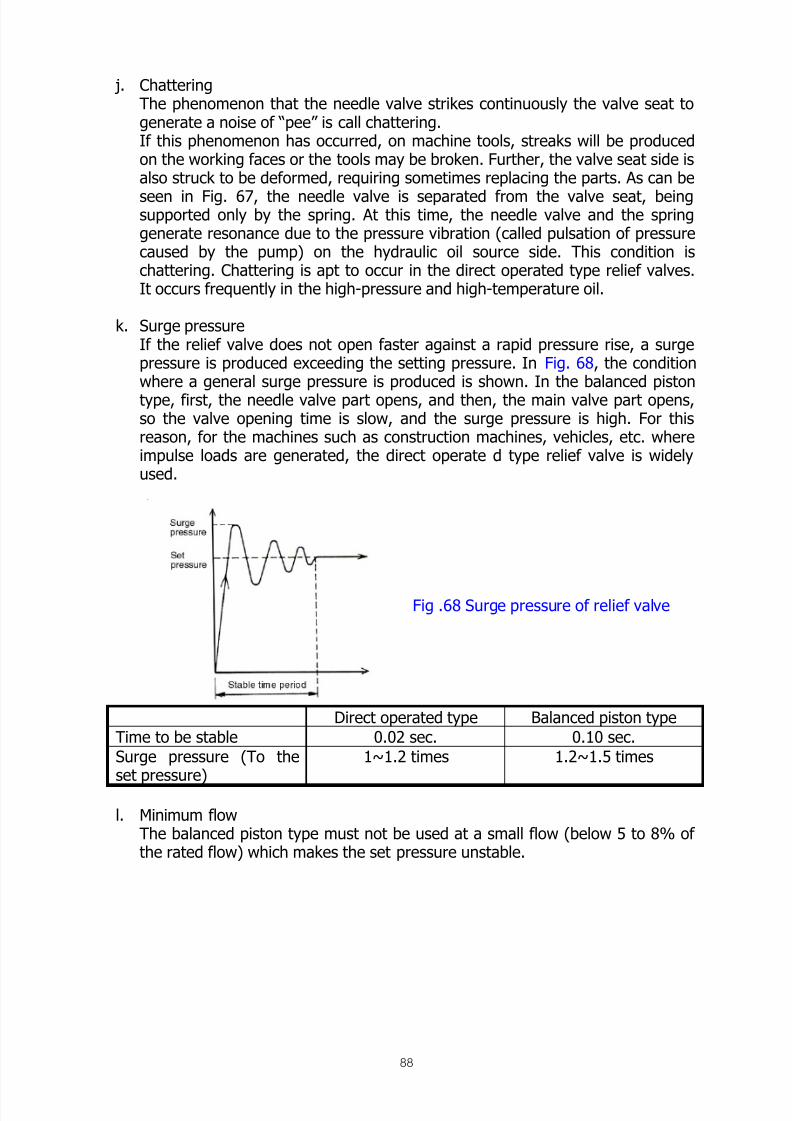
8/12/2019 Fishery Equipment and Hydraulic Engineer
http://slidepdf.com/reader/full/fishery-equipment-and-hydraulic-engineer 88/125
88
j. ChatteringThe phenomenon that the needle valve strikes continuously the valve seat togenerate a noise of “pee” is call chattering.If this phenomenon has occurred, on machine tools, streaks will be producedon the working faces or the tools may be broken. Further, the valve seat side isalso struck to be deformed, requiring sometimes replacing the parts. As can be
seen in Fig. 67, the needle valve is separated from the valve seat, beingsupported only by the spring. At this time, the needle valve and the springgenerate resonance due to the pressure vibration (called pulsation of pressurecaused by the pump) on the hydraulic oil source side. This condition ischattering. Chattering is apt to occur in the direct operated type relief valves.It occurs frequently in the high-pressure and high-temperature oil.
k. Surge pressureIf the relief valve does not open faster against a rapid pressure rise, a surgepressure is produced exceeding the setting pressure. In Fig. 68, the conditionwhere a general surge pressure is produced is shown. In the balanced pistontype, first, the needle valve part opens, and then, the main valve part opens,so the valve opening time is slow, and the surge pressure is high. For thisreason, for the machines such as construction machines, vehicles, etc. whereimpulse loads are generated, the direct operate d type relief valve is widelyused.
Direct operated type Balanced piston type
Time to be stable 0.02 sec. 0.10 sec.
Surge pressure (To theset pressure)
1~1.2 times 1.2~1.5 times
l. Minimum flowThe balanced piston type must not be used at a small flow (below 5 to 8% ofthe rated flow) which makes the set pressure unstable.
Fig .68 Surge pressure of relief valve

8/12/2019 Fishery Equipment and Hydraulic Engineer
http://slidepdf.com/reader/full/fishery-equipment-and-hydraulic-engineer 89/125
89
Reducing Valve This valve is used to limit the pressure on the secondary side (the outlet side ofvalve).When the pressure on the secondary side becomes a set pressure, it is held at theset pressure even if the pressure on the primary side (the entrance side of valve)becomes a higher pressure. Therefore, it becomes possible to use a part of thepressure on the oil hydraulic circuit after being reduced.
1) Direct operated type reducing valve
Fig. 69 Reducing valve
At the starting position, a spool 1 is pushed to the left side by a spring 3, and theprimary side (B port) and the secondary side are opened. The hydraulic oil flows
to an actuator through the B-port and the A-port. The secondary pressure of the A-port acts on the left end face of the spool 1 through a passage 4. When the setpressure which resists the spring 3 is reached, the spool 1 is moved to the right toclose the passage passing from the B-port to the A-port.
As a result, the secondary pressure will not become a pressure above the setpressure.
The flow to be supplied to the secondary side is the flow which the actuatorrequires. If the actuator is stopped, this valve is full closed.
The valve shown in Fig. 69 has in common the function of a safety valve to open apassage from the A-port to the Y-port against. An abnormal high-pressure on thesecondary circuit besides the function of a reducing valve. Reducing valves, whichhave in common no function of the safety valve, are widely used. If any conditionswhere the secondary circuit becomes a pressure exceeding. The set pressure canbe considered. In the cases where an abnormal external force is applied to theactuator in the full closed condition, or where the secondary piping is heated fromthe outside to expand the hydraulic oil in the full closed condition, a safety valve(relief valve) must be installed separately.

8/12/2019 Fishery Equipment and Hydraulic Engineer
http://slidepdf.com/reader/full/fishery-equipment-and-hydraulic-engineer 90/125
90
To make the return oil from the actuator a free flow, a check valve 5 isincorporated.
The G-port is a port for installing a pressure gauge. If not necessary, apply a blindplug.
2) Balanced piston type reducing valve
Fig. 70 Gasket type of reducing valve Fig. 71 Flange type of reducing valve
The reducing valve of a gasket type shown in Fig. 70 and that of a flange typeshown in Fig. 71 are both balanced piston type reducing valves, which are used ina greater flow compared with the direct operated type reducing valves.
Reference numeral 1 designates a direct operated type relief valve, which controlsthe opening and closing of the main piston part of a valve body 2. The main pistonis pushed downward by a spring 8 so that the B-port is full opened to the A-portat the lowest end of the starting position.
The pressure in the A-port acts on the bottom of the main piston, and at the sametime, it acts on a needle valve 7 and the top surface of the main piston through apassage 4 having orifices 5, 6.
When after the pressure in A-port has reached to a set pressure. The needle valvepart is opened the hydraulic oil flows in the passage 4. A pressure drop occurs in
the orifices 5, 6 and the main piston moves upward against the spring 8 to closethe passage from the B-port. It does not follow the pressure in the B-port even if

8/12/2019 Fishery Equipment and Hydraulic Engineer
http://slidepdf.com/reader/full/fishery-equipment-and-hydraulic-engineer 91/125
91
it becomes a high pressure, and the pressure in the A-port does not become apressure above the set pressure.
When the pressure in the B-port to the A-port. As a result, the pressure in the A-port does not follow the pressure in the B-port even if it becomes a high pressure,and the pressure in the A-port does not become a pressure above the set
pressure.
When the pressure in the B-port is above the set pressure, the needle valve part isopened continuously, and a flow of about 1.5 to 2 l/min continues to flow from thedrain port (Y) to the tank.
For this reason, an oil hydraulic circuit having many reducing valves installedrequires an excess pump delivery flow by the flow corresponding to this.
Where a check valve is required to make the flow from the A-port to the B-port a
free flow, an incorporated check valve is employed.
3. Precaution on handling a. Determination of the set pressure
The pressure on the secondary side to be set to a lower pressure isdetermined so that a difference above 10 kgf /cm
2 is produced against the pressureon primary side of a high pressure.
b. Surge pressure As can be seen from the internal structure, the primary side and the
secondary side are opened at the starting position. For this reason, if thesecondary pressure rises abruptly, the secondary pressure becomes a surgepressure exceeding the set pressure due to the delay of action.
Generally, a surge pressure of about 20% is generated. As the differencebetween the primary pressure and the secondary pressure becomes larger, ahigher surge pressure is generated. For this reason, the pressure gauge to beinstalled on the secondary side should be, on a conservative basis, a pressuregauge for high pressures being the same as that to be installed on the primaryside.
c. Unsteadiness of set pressureMany of reducing valves are used in a condition near the full closed
condition. Therefore, if the dust in the oil passes the reducing valves, thesecondary pressure is apt to fluctuate. For this reason, by the use of a fine filterbelow 40 microns, the set pressure will be stabilized.
d. Wear of the needle valveIn the case of the balanced piston type, the wear of the needle valve is the
same as in the relief valves mentioned above.During the pressure is reduced, the needle valve continues to open.
Therefore, it should be noted that the needle valve wears faster than in the caseof relief valve.

8/12/2019 Fishery Equipment and Hydraulic Engineer
http://slidepdf.com/reader/full/fishery-equipment-and-hydraulic-engineer 92/125
92
e. Drain backpressureThe drain pressure should be low as much as possible since the secondary
pressures rises is the drain backpressure. Unlike the relief valves, the secondaryside becomes a high pressure, so external drain is produced.
f. Remote control As in the case of relief valves, remote control becomes possible making use
of the vent connection port (X-port).
Sequence Valve A valve is available as a sequence valve, but its name changes to a relief valve, asequence valve, a counterbalance valve or an unloading valve depending upon itsuse.
A sequence valve is classified into the valves mentioned above from the following
factors : the introduction route of a pilot pressure to open of close the valve isconnected in the valve of led from the outside of the valve ; and when the drainoil leaking to the chamber where the adjustment spring exists is returned to atank, the drain oil is connected to a port connected with the tank or, where such aport does not exist the drain oil is connected to the outside through separatepiping.
The drain oil is connected to the outside through separate piping.
The table below shows the relation between the connection methods and the
names of the valve.
Table 11Name of valve(Application)
Pilot connection Drain connection Dwg. Symbol
Relief valve(For safety)
Internal Internal
Sequence valve
(For order)
Internal External
Counter balance valve(Against back pressure)
Internal / External Internal / External
Unload valve (Unload) External Internal
(Note 1) Showing external pilot and external drain.

8/12/2019 Fishery Equipment and Hydraulic Engineer
http://slidepdf.com/reader/full/fishery-equipment-and-hydraulic-engineer 93/125
93
The relief valve shown in the Table, whose over-ride pressure characteristics areworse, is not used since a special relief valve exists separately.
1) Sequence valve The sequence valve is used to determine the sequence of the operations of
actuators. This is used is a case where a first actuator acts and a second actuatorbegins to act when this sequence valve is opened after the pressure has risen atthe end point of the action.
Fig. 72 shows an example of use using2 sequence valves. The sequence of the
cylinders is as shown in the figure.
Fig. 73 Sequence valve use to secure thepilot pressure for opening of a pilot
operation check valve. (Resistance valve)
In case of a cylinder on the left side is used as clamp for a work, the clamp willnot be loosen during the operation 0f cylinder on the right side.
In the example of use shown in Fig. 73, this valve is used to secure the pilotpressure for opening of a pilot operation check valve.In this application, the sequence valve is also called a resistance valve for itspurpose of use.
2) Counterbalance valve (back pressure valve)
Fig. 74 Counterbalance valve

8/12/2019 Fishery Equipment and Hydraulic Engineer
http://slidepdf.com/reader/full/fishery-equipment-and-hydraulic-engineer 94/125
94
As shown in Fig. 74, a back pressure valve is mounted to a tank return line toprevent an actuator from being moved in an unlimited condition by external force
(in the figure, a load drops at a high pressured by its own weight).
That is, this back pressure valve is used to generate a back pressure on the tankreturn line for preventing the actuator from running away due to the engine ofexternal force.
In the cases of oil hydraulic motors, this valve is necessary in lifting and loweringof winch.
Fig. 74 indicates an internal pilot type. The purpose of the use can be achieved by
either of them, but the setting pressure is different.
3) Unloading valveWhen the external pilot pressure exceeds a set pressure pump becomes anunloading condition from a certain pressure. This circuit is generally called two-pressure control, or low-pressure great flow/high pressure small flow control.
This valve is used in pressing machines, etc. to feed at high speeds in anunloading condition and feed at low speeds in a high loading condition, resulting ina reduced capacity of motor.
Fig. 76 Unloading valve
Fig. 75 Counterbalance valve with orifice

8/12/2019 Fishery Equipment and Hydraulic Engineer
http://slidepdf.com/reader/full/fishery-equipment-and-hydraulic-engineer 95/125

8/12/2019 Fishery Equipment and Hydraulic Engineer
http://slidepdf.com/reader/full/fishery-equipment-and-hydraulic-engineer 96/125

8/12/2019 Fishery Equipment and Hydraulic Engineer
http://slidepdf.com/reader/full/fishery-equipment-and-hydraulic-engineer 97/125
97
Fig. 80
Fig. 80 Balanced piston type sequence valve
6) Precautions on handling
a. Over-ride pressure characteristicsThe characteristics are not so good, so special care should be taken inapplication according to the table of performance described on the catalogue.
b. Previous leak of the sequence valveIf the primary pressure before opening of the sequence valve is close to thepressure to be used on the secondary side, the actuator on the secondary side
often starts to move before opening of the sequence valve due to the leaks inthe valve.
c. Setting pressure of the back pressure valve (external pilot type)The circuit efficiency becomes better as the pressure is lower. But, the settingpressure is set to about 20 to 30 kgf /cm
2 since an unstable condition is apt tooccur.
d. Special back pressure valve without internal leaksThe valves shown above are of a spool type, so oil leaks occur from theclearances of the valve body and the actuator is moved little by little by the
external force. Therefore, the movement of actuator must be stopped byattaching a mechanical brake to the actuator or by the use of a pilot operatedcheck valve.However, it is the best to prevent the oil leaks in the backpressure valve byitself.In a direct operated type back pressure valve (external pilot and internal draintype) shown in Fig. 81, the part 6 of a main spool 2 prevent the oil fromleaking together with a sheet-shape valve seat. Further, this valve is providedwith orifices for damming at the small spool and the main spool 2, so loads canbe lowered with out hunting in truck cranes or winches having frequent
changes in loading.Since the setting pressure is not changed, the spring 3 has no adjustmentscrew.

8/12/2019 Fishery Equipment and Hydraulic Engineer
http://slidepdf.com/reader/full/fishery-equipment-and-hydraulic-engineer 98/125
98
Fig. 81 Special back pressure valve without internal leaks
Directional control valve This valve can be classified into a check valve to prevent back flow and adirectional control valve to change the direction of the flow of hydraulic oil.
Check valveCheck valves include a check valve, which has only the function to prevent backflow, a pilot operated check valve, which permits back flow under a certaincondition, and a pre-filled valve. First, the check valve will be described here.
This valve to make the back flow impossible against a free flow in one directionhas a structure as shown in Fig. 82. Since a valve and a valve seat make contact
with a certain angle, valve opening with out leaks becomes possible. As the valve,as shown in Fig. 82, a check plunger 1 is used, and a steel ball is sometimes used.The cracking pressure (valve opening start pressure) is determined by thestrength of a spring 2, generally being over a range of 0.35 to 8 kgf /cm
2.
If the purpose is only the prevention of back flow, it is better that the passingresistance is smaller. Therefore, a spring of 0.35 to 0.5 kgf /cm
2 is used.
Spring of 3 to 8 kgf /cm2 may be considered as a relief valve without pressure
adjustment. They are used as the by pass in emergency for the filter or oil cooler
provided on tank return circuits, or as the resistance valve.

8/12/2019 Fishery Equipment and Hydraulic Engineer
http://slidepdf.com/reader/full/fishery-equipment-and-hydraulic-engineer 99/125
99
Fig. 82 Check valve
The precautions on use are as follows:1) Prevention of back flow is done, but not perfectly. Some oil leaks exist. When
compared with the spool type valves, the leaks are very small.
2) Change of cracking pressureThe structure permits no adjustments. By inserting a washer in the spring seat,some change becomes possible.If the valve becomes an unstable condition and the unstable condition torepeat valve opening and valve closing occurs, it is better to remove the springor to change the cracking pressure by means of the washer.
Pilot operated checked valve
Fig. 83 Flange type of check valve Fig. 84 Gasket type of check valve
Fig. 83 shows a flange type, and Fig. 84 shows a gasket type. Both valves have afunction to prevent back flow by means of a check plunger 1 and 2 in the sameway as a check valve. Besides this, a pilot piston 4 which is actuated by a pilotpressure at a pilot connection port (X-port) pushes the check plunger 1, 2 to
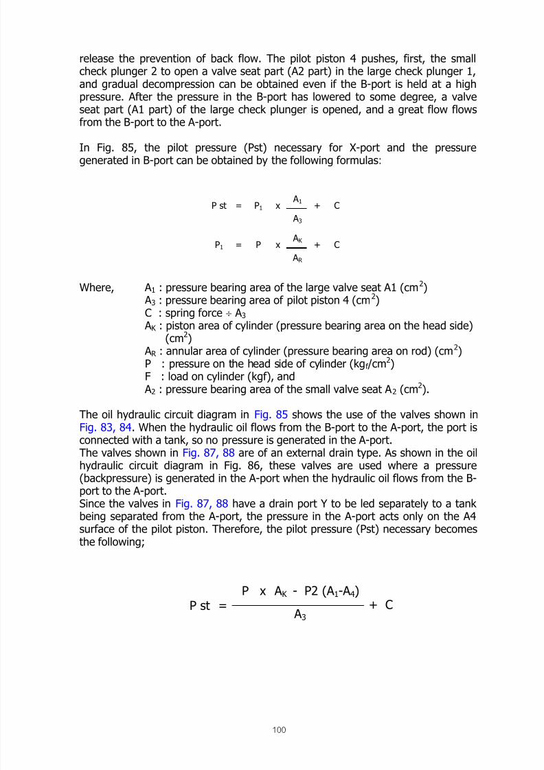
8/12/2019 Fishery Equipment and Hydraulic Engineer
http://slidepdf.com/reader/full/fishery-equipment-and-hydraulic-engineer 100/125
100
release the prevention of back flow. The pilot piston 4 pushes, first, the smallcheck plunger 2 to open a valve seat part (A2 part) in the large check plunger 1,and gradual decompression can be obtained even if the B-port is held at a highpressure. After the pressure in the B-port has lowered to some degree, a valveseat part (A1 part) of the large check plunger is opened, and a great flow flowsfrom the B-port to the A-port.
In Fig. 85, the pilot pressure (Pst) necessary for X-port and the pressuregenerated in B-port can be obtained by the following formulas:
Where, A 1 : pressure bearing area of the large valve seat A1 (cm2) A 3 : pressure bearing area of pilot piston 4 (cm2)C : spring force ÷ A 3
A K : piston area of cylinder (pressure bearing area on the head side)(cm2)
A R : annular area of cylinder (pressure bearing area on rod) (cm2)P : pressure on the head side of cylinder (kgf /cm
2)F : load on cylinder (kgf), and
A 2 : pressure bearing area of the small valve seat A 2 (cm2).
The oil hydraulic circuit diagram in Fig. 85 shows the use of the valves shown inFig. 83, 84. When the hydraulic oil flows from the B-port to the A-port, the port isconnected with a tank, so no pressure is generated in the A-port.The valves shown in Fig. 87, 88 are of an external drain type. As shown in the oilhydraulic circuit diagram in Fig. 86, these valves are used where a pressure(backpressure) is generated in the A-port when the hydraulic oil flows from the B-port to the A-port.Since the valves in Fig. 87, 88 have a drain port Y to be led separately to a tankbeing separated from the A-port, the pressure in the A-port acts only on the A4surface of the pilot piston. Therefore, the pilot pressure (Pst) necessary becomes
the following;
P st = P1 x A 1
A 3
+ C
P1 = P x A K
A R
+ C
P st =P x A K
A 3
- P2 (A 1-A 4)+ C
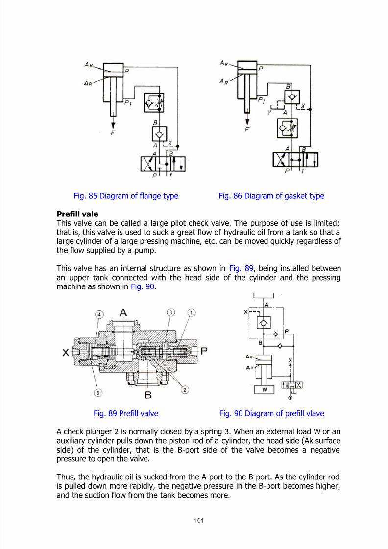
8/12/2019 Fishery Equipment and Hydraulic Engineer
http://slidepdf.com/reader/full/fishery-equipment-and-hydraulic-engineer 101/125
101
Fig. 85 Diagram of flange type Fig. 86 Diagram of gasket type
Prefill vale This valve can be called a large pilot check valve. The purpose of use is limited;that is, this valve is used to suck a great flow of hydraulic oil from a tank so that alarge cylinder of a large pressing machine, etc. can be moved quickly regardless ofthe flow supplied by a pump.
This valve has an internal structure as shown in Fig. 89, being installed betweenan upper tank connected with the head side of the cylinder and the pressing
machine as shown in Fig. 90.
Fig. 89 Prefill valve Fig. 90 Diagram of prefill vlave
A check plunger 2 is normally closed by a spring 3. When an external load W or anauxiliary cylinder pulls down the piston rod of a cylinder, the head side (Ak surfaceside) of the cylinder, that is the B-port side of the valve becomes a negativepressure to open the valve.
Thus, the hydraulic oil is sucked from the A-port to the B-port. As the cylinder rodis pulled down more rapidly, the negative pressure in the B-port becomes higher,and the suction flow from the tank becomes more.

8/12/2019 Fishery Equipment and Hydraulic Engineer
http://slidepdf.com/reader/full/fishery-equipment-and-hydraulic-engineer 102/125
102
At this time, the lowering speed of the cylinder is not related so much to thesupply flows from the pump, being determined by the capacity (size) of this valve.
When the cylinder speed has lowered to a desired speed, a high pressure isgenerated on the head side of the cylinder by the supply flow from a pumpconnected with the P-port, and the check plunger 2 is closed.
The capacity of the pump can be determined from the cylinder speed at highpressure, and the pump becomes a small size. When the cylinder rod is pulled upafter completion of the lowering step, a pilot piston 5 which is actuated by thepilot pressure to the X-port opens the check plunger 2, and the hydraulic oil onthe head side of the cylinder is returned quickly to the tank.
The A-port is connected with the tank, so it is always of atmospheric pressure.This point is different from the pilot check valve mentioned above.
The A-port is connected with the tank, so it is always of atmospheric pressure.This point is differential pressure between A and B ports is basically 0.3 kgf /cm2.
The size of the valve may be determined from this rated flow, or it may bedetermined after obtaining a piping size so that the suction speed becomes 0.8m/sec or less.
If the capacity of the air bleeder is not sufficient, this valve will not act normally.
4.3.4. Types and Classification of Directional Control Valve (Table 12)Classification Symbol Description
2 port Valve have 2 ports
3 port Valve have 3 ports
4 port Valve have 4 ports
1. Number of ports(connection ports)
Multi-port Valve have 5 or more
ports
2 position Valve have 2 positions
3 position Valve have 3 positions
2. Number of
positions to be
switched
Multi-position Valve have 4 or more
positions
All port block Old name is closed
center
3. Shape of flow at
central position
PT connection Called center bypass
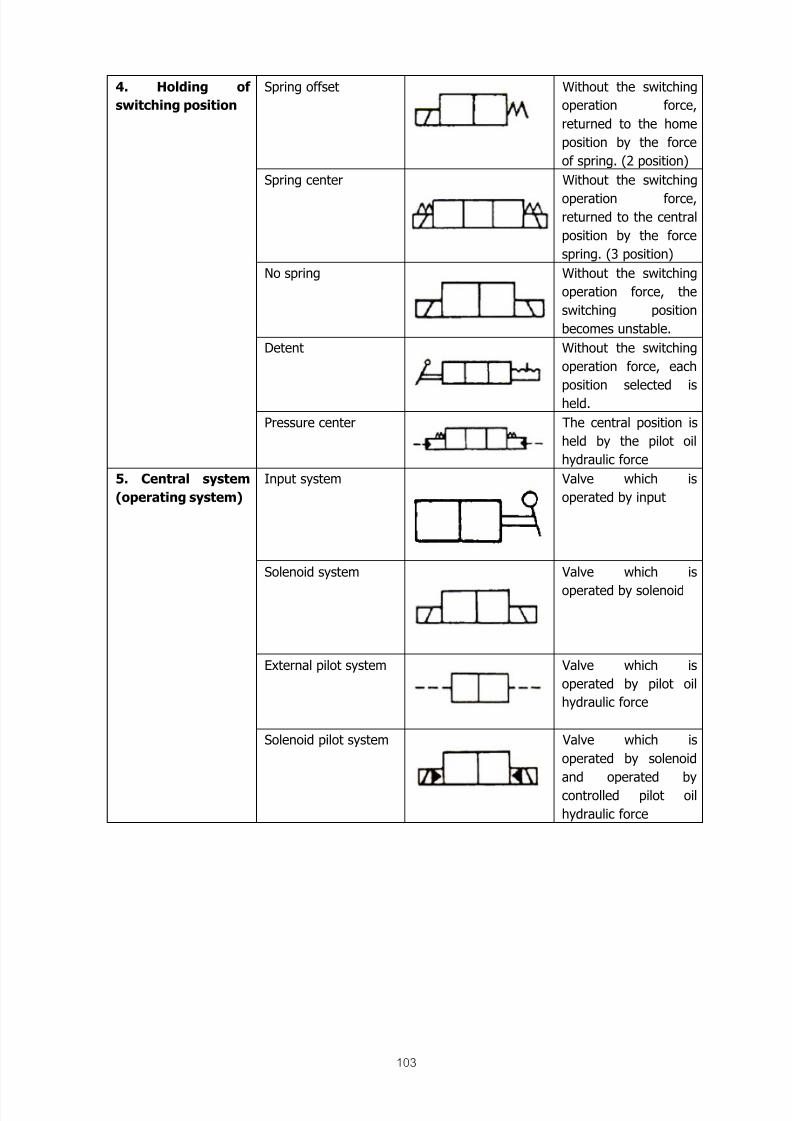
8/12/2019 Fishery Equipment and Hydraulic Engineer
http://slidepdf.com/reader/full/fishery-equipment-and-hydraulic-engineer 103/125
103
Spring offset Without the switching
operation force,
returned to the home
position by the force
of spring. (2 position)
Spring center Without the switching
operation force,returned to the central
position by the force
spring. (3 position)
No spring Without the switching
operation force, the
switching position
becomes unstable.
Detent Without the switching
operation force, each
position selected is
held.
4. Holding of
switching position
Pressure center The central position is
held by the pilot oil
hydraulic force
Input system Valve which is
operated by input
Solenoid system Valve which is
operated by solenoid
External pilot system Valve which is
operated by pilot oil
hydraulic force
5. Central system
(operating system)
Solenoid pilot system Valve which is
operated by solenoid
and operated by
controlled pilot oil
hydraulic force

8/12/2019 Fishery Equipment and Hydraulic Engineer
http://slidepdf.com/reader/full/fishery-equipment-and-hydraulic-engineer 104/125

8/12/2019 Fishery Equipment and Hydraulic Engineer
http://slidepdf.com/reader/full/fishery-equipment-and-hydraulic-engineer 105/125
105
Fig. 94
Fig. 92 uses, as in the case of Fig. 91, an all ports block type directional controlvalve, Fig. 93 uses a PT connection type (center by pass type), and Fig. 94 uses a4 port/2 position type directional control valve.
The precautions on using this valve are as follows:1) Spool symbolsEach maker uses their own spool symbols, and there is no relationship betweenthem.For our products, care should be taken that the flange type and the gasket type
use different spool symbols.
2) Connection condition of each port on the way of switching After completion of the switching, as can be seen from Fig. 92 to 94, theconnection condition of each port is determined by a mechanical stoppingmechanism (stopper). At that time, the flows between individual ports are asshown in the figure. However, the flow between individual ports on the way ofswitching indicates a quite different flow not shown in the figure. The actuatorsometimes shows an unexpected movement only for a short time.In Fig. 95, the condition where the P-port is connected with the T-port is tried tobe switched to the condition where the P-port is connected with the A-port by
moving a spool to the right. Since the dimensions X1 < X2 in the figure, all portsare interrupted and separated from each other only for a short time on the way ofswitching.
At this time, a peak pressure is generated in the P-port, and its magnitudedepends upon the switching time, the flow, and the set pressure of the reliefvalve.
However, in this valve, the actuator has a load, and even if any pressure occurs inthe A-port, there is no risk that the actuator is moved independently by the load
on the way of switching. Thus, the safety is ensured.

8/12/2019 Fishery Equipment and Hydraulic Engineer
http://slidepdf.com/reader/full/fishery-equipment-and-hydraulic-engineer 106/125
106
Fig. 95 Over lap
Fig. 96 under lap
In Fig. 96, since the dimensions changes to X1 > X2, all ports are connected tothe T-port for only a short time before the P-port is separated from the T-port,
and the switching can be made smoothly without occurrence of the peak pressure.
In Fig. 97, since the dimensions X1 = S2, cut off between the P-port and the T-port is made at the same time with the connection between the P-port and the A-port.
This valve is use principally in servo valves, since the fine movement of the spoolcorrectly controls the direction of flow and flow rate.
Thus, over lap, under lap, and zero lap have been described. In the actualproducts, they must be selected understanding well their mechanism.
In our products, as shown in Fig. 98, the symbols on the way of switching arerepresented being enclosed with dotted lines.
Fig. 97 Fig. 98

8/12/2019 Fishery Equipment and Hydraulic Engineer
http://slidepdf.com/reader/full/fishery-equipment-and-hydraulic-engineer 107/125
107
3) Internal leak In the example of Fig. 92, the valve is of all ports block in the center valveposition. As can be seen from the internal structure, oil leaks through the gapsbetween the spool and the body. For this reason, if external force is applied to theactuator, the actuator will move from A to T or from B to T due to the oil leaks.
Further, when a directional control valve of all ports block is used in a parallelcircuit, a cylinder, which is not used may begin to move. This is because the A-andB-ports becomes the same due to the leaks from P-->A and P-->B ports, andforce is applied in the direction of expansion depending upon the difference inpressure beating area.
To prevent this, as shown in Fig. 85 in Page 102, the use of a pilot operated checkvalve or the employment of a directional control valve of A, B, T connection type isnecessary.
4) Passing resistance The passing resistance for the flows between individual ports is described clearlyin graphs in the catalogue. When using them, the sum of the passing resistancefrom P-port to A-port and the passing resistance from B-port to T-port is theincrement of the load pressure of the pump. If the actuator is a cylinder, it mustbe noted that the flow of the tank return side is often larger than the inflow flowbecause of the difference in pressure bearing area.
Solenoid Valve This valve is also called solenoid valve. Iron cores are moved by the excitation of
an electromagnet incorporated, and a spool is moved by the force generated toswitch the direction of flow between individual ports. By adding the characteristic sof electricity to the characteristics of oil hydraulics, it becomes possible to makeremote control, automatic etc. Therefore, this valve is used widely.
According to the structure of electromagnet and the electric sources applied, there4 types as follows:
1) Dry dc. solenoid valve2) Dry ac. solenoid valve3) Oil-immersed dc. solenoid valve4) Oil-immersed dc. solenoid valve
In the dc. solenoid valve, even if the spool stops on the way of switching, theelectromagnet will not generated heat, and the switching can be made smoothly.This valve is suited where the switching frequency is so often (the frequency of250 times of switching pre minute becomes possible, about twice the case of a.c.).
The feature of the ac. solenoid valve is that switching time is short (about 1.5 to 2times the case of dc., 30 ms = 0.03 sec). If the spool does not move on the wayof switching, the coil will be burnt (after lapse of 1 to 1.5 hours for the oil-immersed type, and 10 to 15 minutes for the dry type). The dry electromagnethas a simple structure, being low in cost. The feature of the oil-immersed
electromagnet is a long switching life of 20,000,000 times, about 4 times that ofthe dry type. To compare both types more easily, the dry dc. electro-magnet 1 isshown on the left side of Fig. 99, and the dry dc. electro-magnet 2 is shown on

8/12/2019 Fishery Equipment and Hydraulic Engineer
http://slidepdf.com/reader/full/fishery-equipment-and-hydraulic-engineer 108/125
108
the right side of Fig. 99. In both types, the hydraulic oil from the T-port is adaptednot to enter the magnet iron core part by a seal installed on a bush 3.
Further, since the 2 springs exercise no force on the spool, the spool stops oneither side, which is pushed by the electromagnet to form a 2 position directionalcontrol valve.
In the next Fig. 100, the oil-immersed dc. electro-magnet 4 is shown on the leftside, and the oil-immersed ac. electromagnet 5 is shown on the right side. Thechamber of the movable iron core part is connected with the T-port.
Since the 2 springs 6 have force to return the spool toward the central position, itforms a 3-position directional control valve. Both Fig.99 and 100 have emergencymanually operated pushbuttons 7, which are used also to confirm the switchingfunction of the solenoid valve manually.
Fig. 99 dry dc. electromagnet
Fig. 100 oil-immersed dc. electromagnet
The precautions on the use of this valve are as follows;
1)
Maximum flow for each spoolThe output of the magnet to push the spool for switching is about 4 to 5 kgf atthe middle point of the stroke, being very weak force.The force for returning the spool to the central position by hydraulic forcebecomes larger depending upon the flow. Thus, the maximum flow isdetermined.The hydraulic force is different depending upon the shape of spool. Note themaximum flow for each spool stated on the catalogue.Further, the output of the magnet is different between a dc. magnet and anac. magnet, so the maximum flow becomes different.
2)
Power sourceGenerally, according to ac. or dc., to the difference in voltage, or to thedifference in frequency, the magnet must be changed.

8/12/2019 Fishery Equipment and Hydraulic Engineer
http://slidepdf.com/reader/full/fishery-equipment-and-hydraulic-engineer 109/125
109
In our products, for both WE6 type and WE10 type, 6 types are available asthe standard:
dc. magnet; for 12V, 24Vac. magnet (for both 50 Hz and 60 Hz)
110V, 200V, 220VIf the voltage is not used within a range of ±10% malfunction due to
insufficient output or failure due to abnormal heat development in the coil willoccur.
3) Waterproof and explosion-protection
Pilot Operated Valve with Solenoid Control The solenoid valve mentioned above includes a product having maximum flow ofabout 100 l/min. If a larger valve than it is desired, the magnet becomes so large,and the price becomes very high. Therefore, the pilot operated valve with solenoidcontrol is used, which combines a solenoid valve and a pilot operated directionalvalve.
Fig. 102 Pilot operated valve with solenoid control
In the valve shown in Fig. 102, the hydraulic oil introduced from the X-port, asintroduction port for external pilot pressure, is led into a chamber 6 or 7 of a pilotoperated directional valve 2 by the action of a solenoid valve 1. So that a mainspool 3 is moved to switch the direction of a large flow.
The structure of the valve in Fig. 102 is called as follows:
External pilot type
External drain type
Spring center type
All port block type
With tarry valve type
External pilot type
External drain type
Spring center type
All port block type
With tarry valve type

8/12/2019 Fishery Equipment and Hydraulic Engineer
http://slidepdf.com/reader/full/fishery-equipment-and-hydraulic-engineer 110/125

8/12/2019 Fishery Equipment and Hydraulic Engineer
http://slidepdf.com/reader/full/fishery-equipment-and-hydraulic-engineer 111/125
111
The valve in Fig. 102 is of the spring center type. When the solenoid valve 1 isat the center valve position, the chambers 6 and 7 are connected with the Yport (a drain port connected with the tank), and the main spool 3 holds thecenter valve position or returns to the center valve position by the springs.The valve shown in Fig. 104 is of the pressure center type. When the solenoidvalve is at the center valve position, the pilot pressure is into the chambers 6,
7, and a centering bush 8. A centering rod 9 make the main spool 3 forcedlyold the center valve position or return to it by means of oil by hydraulicpressure.
When comparing the pressure center type with the spring center type, thefollowing can be said:a) Fast switching sped. (Take care that shocks are apt to occur.)b) When the backpressure of drain port is high due to fat distance to the tank,
the switching speed becomes faster, and the operation is made exactly.c) In our products, a spring is provided at both end parts of them main spool
3. Even if the pilot pressure becomes zero due to pour interruption, etc.,the main spool 3 can return to the center valve position. However, in thevalves, which have no springs, care should be taken that the safety
criterion for press, etc. becomes unacceptable.d) Separate piping for the drain port L becomes necessary.
4) Types of spools As in the cases of the manual directional control valve and the solenoid valve,various types are available.
5) Tarry valveThis valve, which is generally called a throttle check valve with check valve(double type), is installed between a solenoid valve 1 and a pilot operated
directional valve 2 in Fig. 102.By installing this valve, the pilot flow to the chamber 6 or 7 can be adjusted, sothe moving speed of the main valve 3, that is, the switching speed can becontrolled.
Fig. 104

8/12/2019 Fishery Equipment and Hydraulic Engineer
http://slidepdf.com/reader/full/fishery-equipment-and-hydraulic-engineer 112/125
112
From this fact, the start of the actuator can be smoothly accelerated. Next, theoperating procedure and the symbols will be described.In the valve shown in Fig. 102, when the magnet on the right side of thesolenoid valve 1, the spool of the solenoid valve is moved to the left side. Thepilot pressure reaches the chamber 6, the main spool 3 is moved to the rightagainst the spring and the flow rate of P--> B port or A-->T port is generated.
Since the chamber 7 is connected with the drain port Y, the main spool 3 canbe moved. The return to the center valve position was described above, so itsdescription will be omitted.The symbol of the valve in Fig. 102 is shown in Fig. 105, and the simplifiedsymbol generally used is shown in Fig. 106. In the symbols, by the excitationof the magnet a or b, what a flow the pilot selector valve side is switched to isshown. The mark “0” shows the center valve position.
Fig. 105
Fig. 106
In the valve shown in Fig. 104, the operating procedure and the symbols are
as follows:When the right electromagnet of the solenoid valve is excited, the spool of
the solenoid valve is moved to the left side, the chamber 6 receives the pilotpressure as it is, and the other chamber 7 is connected with the drain port Y sothat its pressure becomes zero. The main spool 3 is pushed to the right side bythe centering rod 9 to generate the flow of P-->B port or A-->T port. Whenthis valve is used vertically, even if the pilot pressure becomes zero, thesprings existing in the chambers 6, 7 ensure that the main spool is at thecenter valve position. When the electromagnet at the right side isdemagnetized, the chambers 6, 7 become the pilot pressure. Since the
pressure bearing area of the main spool 3 is larger than that of the centeringrod 9, the main spool moves to the left. However, since the pressure bearingarea of the sum of the centering rod 9 and the centering bush 8 is larger, the
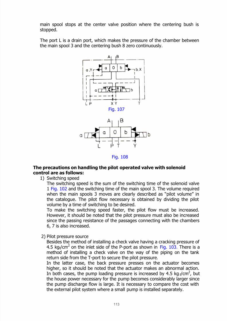
8/12/2019 Fishery Equipment and Hydraulic Engineer
http://slidepdf.com/reader/full/fishery-equipment-and-hydraulic-engineer 113/125
113
main spool stops at the center valve position where the centering bush isstopped.
The port L is a drain port, which makes the pressure of the chamber betweenthe main spool 3 and the centering bush 8 zero continuously.
Fig. 107
Fig. 108
The precautions on handling the pilot operated valve with solenoidcontrol are as follows:1) Switching speed
The switching speed is the sum of the switching time of the solenoid valve1 Fig. 102 and the switching time of the main spool 3. The volume requiredwhen the main spools 3 moves are clearly described as “pilot volume” inthe catalogue. The pilot flow necessary is obtained by dividing the pilotvolume by a time of switching to be desired.To make the switching speed faster, the pilot flow must be increased.However, it should be noted that the pilot pressure must also be increasedsince the passing resistance of the passages connecting with the chambers
6, 7 is also increased.
2) Pilot pressure sourceBesides the method of installing a check valve having a cracking pressure of4.5 kgf /cm
2 on the inlet side of the P-port as shown in Fig. 103. There is amethod of installing a check valve on the way of the piping on the tankreturn side from the T-port to secure the pilot pressure.In the latter case, the back pressure presses on the actuator becomeshigher, so it should be noted that the actuator makes an abnormal action.In both cases, the pump loading pressure is increased by 4.5 kg f /cm
2, but
the house power necessary for the pump becomes considerably larger sincethe pump discharge flow is large. It is necessary to compare the cost withthe external pilot system where a small pump is installed separately.

8/12/2019 Fishery Equipment and Hydraulic Engineer
http://slidepdf.com/reader/full/fishery-equipment-and-hydraulic-engineer 114/125
114
Pilot Operated Directional Valve (oil hydraulic pilot operated directionalvalve)
The valve shown Fig. 109 is a 3 port / 4 position directional control valve.The spool 1 is moved to the right by an oil hydraulic pressure (or air pressure)exerting on a piston 2 on the left side which is led from the outside, being held ina detect 3.
Fig. 109
If the oil hydraulic pressure exerting on the piston 2 is removed, theswitching condition will be held, but the oil hydraulic pressure acting on the pistonfrom the right side will switch the valve. Since the switching speed is determinedby the hydraulic supply flow led from the outside, it becomes possible to switchcomparatively slowly. Further, it is possible to make remote control, which is onefeature of this valve.
Flow control valve
This valve controls the passing flow in the valve step less. As a result, thisvalve is used to change the opening and closing speed of each valve, or to adjustthe changing speed of the displacement of variable displacement pumps. Thevalve can be classified into a throttle check valve and a pressure compensatedflow control valve.Throttle check valve Fig. 110 shows a high-pressure (300 kgf /cm
2) PT screw type, both of which have acheck valve 2.
Fig. 110

8/12/2019 Fishery Equipment and Hydraulic Engineer
http://slidepdf.com/reader/full/fishery-equipment-and-hydraulic-engineer 115/125
115
Fig. 111+
The flow is controlled by the size of the opening area of the throttling part 1,which can be adjusted from the outside. However, the flow from the B-port to the
A-port becomes a free flow when a check valve has been provided.
The check valve incorporated in the valve shown in Fig. 111 uses a steel ball.
The flow passing the throttling part 1 can be represented by the equation shownbelow (this represents the passing flow of orifice and the case of choke isrepresented by another equation):
Where,
A = opening area of the throttling part,γ = specific weight of hydraulic oil = 0.86 to 0.9 kgf /L
P A , PB = pressure P A before the throttling part, pressure PB after the throttling part,
g = gravitational acceleration = 9.8 m/sec
dH = opening diameter of the throttling part (except acircle, obtained by the following formula)
= 4 x A/U
Where, A = opening area of the throttling part,U = circumferential length of the opening part,i. = length of the throttling part,ν = kinematic viscosity, and
V = Mean flow speedB. The shape of throttling part determines by flow coefficient C. Generally,
being 0.6 to 0.9. When the flow coefficient C=0.7 and the specific gravity ofoil = 0.9 kgf /L, the passing flow Q is show in Fig. 112.C.
Q = C A 2 P A – PB
γ
C = DH V
64 ι ν

8/12/2019 Fishery Equipment and Hydraulic Engineer
http://slidepdf.com/reader/full/fishery-equipment-and-hydraulic-engineer 116/125
116
Fig. 112
From the calculation formula mentioned valve, the flow of a throttle check valve
increases as the pressure difference (P A -PB) between after and before thethrottling part increases. Further, as the length of the throttling part becomesshorter, the change in the kinematics viscosity ν, which is greatly affected by thetemperature of oil, becomes un-remarked, and the change in setting flow becomessmall. That is, if the temperature of oil rises and the viscosity becomes low, theflow coefficient C becomes larger, and the flow at the throttling part increases. Insuch a case, if the structure of the throttling part is formed of a thin orifice insteadof a choke, the increment can be restricted.
Trying to calculation how the setting pressure changes depending upon thepressure difference between before and after the throttling part. As an example,
the pressure P A at the outlet changes from 0 kgf /cm2 to 100 kgf /cm2 dependingupon the load of the actuator. At this time, the rate of flow change β becomes:
β =
C A2 g (P A – PB’)
γ
C A2 g (P A – PB)
=P A – PB’
(P A – PB)
=
(140 – 100)
(140 – 0)

8/12/2019 Fishery Equipment and Hydraulic Engineer
http://slidepdf.com/reader/full/fishery-equipment-and-hydraulic-engineer 117/125
117
That is, the flow becomes almost a half. If there is no problem about the rate offlow charge β thus calculated, it is not necessary to use the expensive flow controlvalve (flow control valve) that will be mentioned next. Further, if a load iscontinuously applied to the actuator and the change of the load is small, and theuse of a throttle check valve is sufficient.
Flow control valve
This is a valve incorporated with a pressure compensating mechanism to hold aconstant setting pressure even if any pressure difference occurred between theentrance and outlet of a valve.
By the use of the pressure compensating mechanism, the rate of flow change canbe controlled to ±2 to 4%. If more accuracy is required, an electro-hydraulic servovalve or a solenoid proportional flow control valve may be used.
Fig. 113
To understand better the function of this valve, the oil hydraulic circuit diagramshown in Fig. 113 will be described first. The oil hydraulic circuit is used to adjustthe rotating speed of an oil motor, being a flow regulating system by means of ameter-in circuit system.
The hydraulic oil discharged from the pump is divided into a flow, which the oilhydraulic motor requires (set by the flow control valve) and excess oil to escape
from the relief valve.
This means that the relief valve is normally opened and the setting pressure of therelief valve is always the pressure P1 at the entrance (A-port) of the flow controlvalve. Further, the pressure P3 at the outlet (B-port) of the valve changesdepending upon the magnitude of the load acting on the oil motor. In the valve, athrottling part 1 and a pressure compensating mechanism 2 are provided, and thepressure at the area connecting them is P2.
The pressure compensating mechanism 2 consists of a compensator spool and a
spring to reduce the pressure P1 to the pressure P2. The pressure P2 acts on theupper surfaces A2 of the compensator spool and the pressure P3 acts on the lowersurfaces A3. The relation of the force acting on the compensator spool can beshown by the following equation:

8/12/2019 Fishery Equipment and Hydraulic Engineer
http://slidepdf.com/reader/full/fishery-equipment-and-hydraulic-engineer 118/125
118
P2 x A2 = P3 x A3 + spring force FIf A2 = A3and A2, A3 = A, the equation can be converted to the following:
P2 – P3 = F / A = generally, 5 to 7 kgf /cm2
As can be seen from this equation, the pressure drop (P2-P3) at the throttling part1 is always corresponding to the spring force F. Since the deflection of the spring
is vary small, the spring force F may be considered as a constant valve. Forexample, if the load increases and the pressure P3 rises, the compensator spool ispushed up to reduce the pressure reducing effect, and the pressure P2 rises. As aresult, both pressures rises become equal, and the compensator spool takes abalanced condition.
That is, even if the pressure P3 changes to any degree due to the load change.The differential pressure (P2-P3) before and after the throttling part is normallyheld constant. Therefore, the passing flow of the valve is kept at the setting flow.
To change the setting flow, the opening of the throttling part 1 may be changed.Fig. 114 shows the structure of an actual valve. The throttling part consists of athrottle pin 2 and a sleeve 3. The pressure compensating mechanism consists of acompensator spool 4 and a spring 5.
To make possible a free flow from the B-port to the A-port, a check valve 6 isattached. Therefore, the flow control operates effectively only for the flow from A-port to B-port.
The pressure P2 before the throttling part acts on the end face of thecompensator spool on the opposite side of the spring through a hole 7. The
pressure P3 on the outlet side after throttling part gives force to the compensatingspool in the same direction as the spring force through a hole 8. A valveincorporated with a stroke limited 9 is available, which can control to the minimuma flow exceeding a setting flow instantaneous when the hydraulic oil begins toflow. The reason that the compensating spool 4 has moved to the stroke end bythe force of the spring when the hydraulic oil does not flow. So that the area to beopened is full open, so the pressure P2 exceeds temporarily the entrance pressureP1 when the hydraulic oil abruptly begins to flow).
Fig. 114
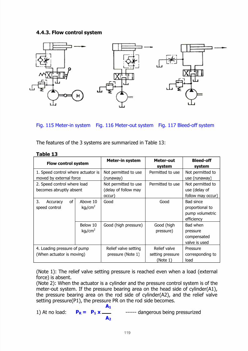
8/12/2019 Fishery Equipment and Hydraulic Engineer
http://slidepdf.com/reader/full/fishery-equipment-and-hydraulic-engineer 119/125
119
4.4.3. Flow control system
Fig. 115 Meter-in system Fig. 116 Meter-out system Fig. 117 Bleed-off system
The features of the 3 systems are summarized in Table 13:
Table 13
Flow control systemMeter-in system Meter-out
system
Bleed-off
system
1. Speed control where actuator is
moved by external force
Not permitted to use
(runaway)
Permitted to use Not permitted to
use (runaway)
2. Speed control where loadbecomes abruptly absent
Not permitted to use(delay of follow may
occur)
Permitted to use Not permitted touse (delay of
follow may occur)
Above 10
kgf /cm2
Good Good Bad since
proportional to
pump volumetric
efficiency
3. Accuracy of
speed control
Below 10
kgf /cm2
Good (high pressure) Good (high
pressure)
Bad when
pressure
compensated
valve is used
4. Loading pressure of pump
(When actuator is moving)
Relief valve setting
pressure (Note 1)
Relief valve
setting pressure
(Note 1)
Pressure
corresponding to
load
(Note 1): The relief valve setting pressure is reached even when a load (externalforce) is absent.(Note 2): When the actuator is a cylinder and the pressure control system is of themeter-out system. If the pressure bearing area on the head side of cylinder(A1),the pressure bearing area on the rod side of cylinder(A2), and the relief valvesetting pressure(P1), the pressure PR on the rod side becomes.
1) At no load: ------ dangerous being pressurizedPR = P1 x A1
A2

8/12/2019 Fishery Equipment and Hydraulic Engineer
http://slidepdf.com/reader/full/fishery-equipment-and-hydraulic-engineer 120/125

8/12/2019 Fishery Equipment and Hydraulic Engineer
http://slidepdf.com/reader/full/fishery-equipment-and-hydraulic-engineer 121/125
121
Basic Design and Planning of hydraulic winch
The processes of designing hydraulic winch are given by the haulingcapacity (tensile strength) in ton and the number of hauling speed or winchvelocity (m/min.).
At first the diameter of winch is considered for this purpose the total length
of rope should be determined to obtain above the radius.The total of rope wound up on to the winch at one layer can be calculated
by the following formula.
d
b =m
Where:
m = The total number of rope wound up on the winch (turns )
dr = Diameter of rope ( mm )B = Width of reel
The diameter of drum at N-layer is expressed by the following formula:
d1)-(2N Dd Ddn +=
The total length of wire rope for N-layer can be expressed as follows:
⎥⎦⎤
⎢⎣⎡ += )d1-(2N Ddm
1000
1 Ldn
π
Therefore, the total length of rope in each layer from the first-layer to last-layer can be computes one by one.
Shaft torque of winch at the rating point is expressed by:
Td = 1000 rd F
Where:
Dd = Diameter of drum without rope. (mm).
Ddn = Diameter of drum including with rope at the determine layer (mm).
N = The number of rope wound up on the winch (turns).
Ldn = The lengths of rope wound up on the winch at determine layer (m).
rd = The radius from the drum center to the rope center at determinelayer (mm).
F = Working force (Kg).

8/12/2019 Fishery Equipment and Hydraulic Engineer
http://slidepdf.com/reader/full/fishery-equipment-and-hydraulic-engineer 122/125
122
Calculation
1. 2
D
1000
1r ×⎟
⎠
⎞⎜⎝
⎛ =
2. rFTd =
3. r2
V
Π Nd =
4. ηT
wM ×
=R
T
w
D
5. N N DM R w=
6. η
PΔvp
MQ =
7. η
NQ
vM
MM
q M
=
8. P P cΔΔP +=
9. η
QPvP
MQ =
10. R
qE
PN
Q
N
Q
E
P
P
P ==
11. ηηη450
PL
mR mPH
4500
FV
Q P ≈=
Where:
D = Diameter including ropes wound over at the rate point (mm)
ηw = Mechanical efficiency of winch ≅ 0.9
Qm = Theoretical flow quantity of motor per one revolution (l/rev)
ηmM = Mechanical efficiency of hydraulic motor ≅ 0.8 – 0.9
ηvM = Volumetric efficiency of hydraulic motor ≅ 0.85 – 0.95
PΔ c = Pressure loss of valves and pipes, etc. Kg/cm2
ηvP = Volumetric efficiency of hydraulic pump ≅ 0.85 – 0.95
ηmP = Mechanical efficiency of hydraulic pump ≅ 0.9 – 0.95QP = Theoretical flow quantity of pump per one revolution (l/rev)
NE = Engine speed which drive the hydraulic pump (rpm)
R E = Ratio of acceleration communicated from engine speed to
hydraulic pump.
ηmR = Mechanical efficiency of acceleration ≅ 0.95 – 0.97
ηtotal = Total efficiency of hydraulic transmission
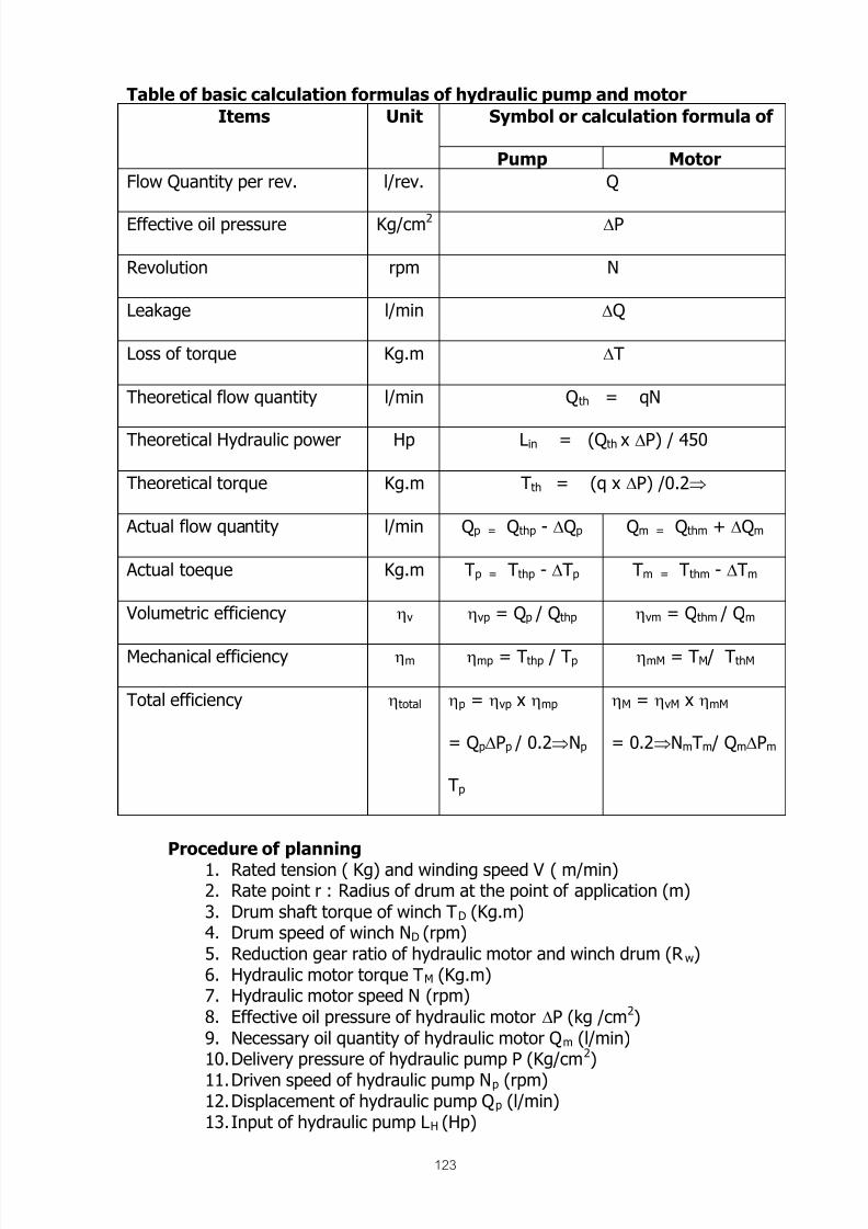
8/12/2019 Fishery Equipment and Hydraulic Engineer
http://slidepdf.com/reader/full/fishery-equipment-and-hydraulic-engineer 123/125

8/12/2019 Fishery Equipment and Hydraulic Engineer
http://slidepdf.com/reader/full/fishery-equipment-and-hydraulic-engineer 124/125
124
Reference
Y. Asai Hauling device SEAFDEC TRAINING DEPARTMENT BANGKOK THAILAND
Uchida company Hydraulic technical handbook, Japan
Kawasaki company Hydraulic technical handbook, Japan
Japan international cooperation agency Lecture note Kanagawa internationalfisheries training center, Japan

8/12/2019 Fishery Equipment and Hydraulic Engineer
http://slidepdf.com/reader/full/fishery-equipment-and-hydraulic-engineer 125/125