Fisher V270 Full-Bore Ball Control Valve
20
www.Fisher.com Fisher ™ V270 Full-Bore Ball Control Valve Contents Introduction 1 ................................. Scope of Manual 1 ............................. Description 1 ................................. Specifications 2 ............................... Educational Services 3 ......................... Installation 3 .................................. Maintenance 6 ................................. Packing Maintenance 6 ......................... Stopping Leakage 6 ........................ Replacing Packing 7 ........................ Seal Ring Maintenance Disassembly 9 ............................. Assembly 11 .............................. Actuator Mounting 13 ........................... Determining Closed Position 14 ................. Parts Ordering 14 ............................... Parts List 16 ................................... Figure 1. Fisher V270 Control Valve X1492 Introduction Scope of Manual This instruction manual provides installation, operation, maintenance, and parts information for the Fisher V270 Full-Bore Ball control valve (see figure 1). Refer to separate manuals for information concerning the actuator, positioner, and accessories. Do not install, operate, or maintain a V270 valve without being fully trained and qualified in valve, actuator, and accessory installation, operation, and maintenance. To avoid personal injury or property damage, it is important to carefully read, understand, and follow all the contents of this manual, including all safety cautions and warnings. If you have any questions about these instructions, contact your Emerson sales office or Local Business Partner before proceeding. Description The Fisher V270 is a three piece, trunnion mounted, full-bore control valve designed with features for optimized pressure, flow and process control. The V270 comes standard with dual seal construction allowing unidirectional or bidirectional flow and double block-and-bleed operation. The full-bore ball design presents little or no restriction to flow at full travel. The V270 construction meets ANSI / NACE MR0175 / ISO 15156 as standard. Instruction Manual D104297X012 V270 Valve June 2017
Transcript of Fisher V270 Full-Bore Ball Control Valve

www.Fisher.com
Fisher™ V270 Full-Bore Ball Control Valve
ContentsIntroduction 1. . . . . . . . . . . . . . . . . . . . . . . . . . . . . . . . .
Scope of Manual 1. . . . . . . . . . . . . . . . . . . . . . . . . . . . .Description 1. . . . . . . . . . . . . . . . . . . . . . . . . . . . . . . . .Specifications 2. . . . . . . . . . . . . . . . . . . . . . . . . . . . . . .Educational Services 3. . . . . . . . . . . . . . . . . . . . . . . . .
Installation 3. . . . . . . . . . . . . . . . . . . . . . . . . . . . . . . . . .Maintenance 6. . . . . . . . . . . . . . . . . . . . . . . . . . . . . . . . .
Packing Maintenance 6. . . . . . . . . . . . . . . . . . . . . . . . .Stopping Leakage 6. . . . . . . . . . . . . . . . . . . . . . . .Replacing Packing 7. . . . . . . . . . . . . . . . . . . . . . . .
Seal Ring MaintenanceDisassembly 9. . . . . . . . . . . . . . . . . . . . . . . . . . . . .Assembly 11. . . . . . . . . . . . . . . . . . . . . . . . . . . . . .
Actuator Mounting 13. . . . . . . . . . . . . . . . . . . . . . . . . . .Determining Closed Position 14. . . . . . . . . . . . . . . . .
Parts Ordering 14. . . . . . . . . . . . . . . . . . . . . . . . . . . . . . .Parts List 16. . . . . . . . . . . . . . . . . . . . . . . . . . . . . . . . . . .
Figure 1. Fisher V270 Control Valve
X1492
Introduction
Scope of ManualThis instruction manual provides installation, operation, maintenance, and parts information for the Fisher V270Full-Bore Ball control valve (see figure 1). Refer to separate manuals for information concerning the actuator,positioner, and accessories.
Do not install, operate, or maintain a V270 valve without being fully trained and qualified in valve, actuator, andaccessory installation, operation, and maintenance. To avoid personal injury or property damage, it is important tocarefully read, understand, and follow all the contents of this manual, including all safety cautions and warnings. If youhave any questions about these instructions, contact your Emerson sales office or Local Business Partner beforeproceeding.
DescriptionThe Fisher V270 is a three piece, trunnion mounted, full-bore control valve designed with features for optimizedpressure, flow and process control. The V270 comes standard with dual seal construction allowing unidirectional orbidirectional flow and double block-and-bleed operation. The full-bore ball design presents little or no restriction toflow at full travel. The V270 construction meets ANSI / NACE MR0175 / ISO 15156 as standard.
Instruction ManualD104297X012
V270 ValveJune 2017

Instruction ManualD104297X012
V270 ValveJune 2017
2
Specifications
Valve Body Size
� NPS 6, � 8, � 10, � 12, � 14, � 16, � 20,and � 24.
Body/Shell Pressure Rating(1)
� CL150, � CL300, and � CL600pressure‐temperature ratings per ASME B16.34-2013
Valve Body, Tailpiece and Packing Box Material
SA350 LF2
Ball Material
SA350 LF2/ENP
Seal/Insert Material(2)
S31600/POM
Packing
Live-Loaded PTFE
Valve Temperature Capability
-40 to 82�C (-40 to 180�F)
End Connections
Raised Face per B16.5-2013
Shaft Connection Style
Keyed
Face-to-Face Dimensions
Long Pattern per B16.10-2009
Shutoff Classification
ANSI/FCI 70‐2 Class VI
Flow Direction
Unidirectional or Bidirectional flow
Flow Characteristic
Modified equal percentage
Maximum Ball Rotation
90 degrees
Approximate Weight
See table 2
1. The pressure‐temperature limits in this instruction manual and any applicable standard or code limitation for valve should not be exceeded.2. POM stands for polyoxymethylene
Table 1. Standard Materials of ConstructionPart Material
Valve Body LF2 Carbon Steel
Ball LF2 Carbon Steel / ENP
Seal POM with S31600 SST Seal Carrier
Drive Shaft S17400 H1150D
Spring N07750
Tailpiece LF2 Carbon Steel
Tailpiece Mounting and Packing Box Bolting L7M Steel
Bearing Plate LF2 Carbon Steel
Trunnion Bushings Carbon Steel, Bronze, PTFE
Thrust Washer Glass filled PTFE
Shaft Bushing N04400 / Comp
Packing Box Housing Carbon Steel
Packing Live-Loaded PTFE
Packing Bolting B7M Steel
Packing Follower, Packing Box Ring S31600 SST
Straight Pins S17400 H1150D
O-Rings, Backup Rings Nitrile
Actuator Mounting Bolting Steel Grade 5

Instruction ManualD104297X012
V270 ValveJune 2017
3
Educational ServicesFor information on available courses for Fisher V270 valves, as well as a variety of other products, contact:
Emerson Automation SolutionsEducational Services - RegistrationPhone: 1-641-754-3771 or 1-800-338-8158E-mail: [email protected]/fishervalvetraining
Installation
WARNING
� To avoid personal injury, always wear protective gloves, clothing, and eyewear when performing any installationoperations.
� To avoid personal injury or property damage resulting from the bursting of pressure retaining parts, be certain theservice conditions do not exceed the limits given in this manual.
� To avoid personal injury or property damage that can result from the sudden release of process pressure if valve ormating pipe flange pressure ratings are exceeded, provide a relief valve for over‐pressure protection as required bygovernment or accepted industry codes and good engineering practices.
� Personal injury could result from packing leakage. See the Packing Maintenance section for adjustment information.
� Check with your process or safety engineer for any additional measures that must be taken to protect against processmedia.
� If installing into an existing application, also refer to the WARNING at the beginning of the Maintenance section in thisinstruction manual.
� Use proper lifting and rigging practices while moving the valve or valve/actuator assembly.

Instruction ManualD104297X012
V270 ValveJune 2017
4
Table 2. Face‐to‐Face Dimensions and Approximate Weights
VALVE SIZE, NPS CLASS
FACE‐TO‐FACEDIMENSIONS
APPROXIMATE WEIGHT
mm Inches kg Pounds
6
150 394 15.50 170 370
300 403 15.88 190 415
600 559 22.00 280 620
8
150 457 18.00 305 670
300 502 19.75 350 775
600 660 26.00 465 1020
10
150 533 21.00 430 950
300 568 22.38 495 1095
600 787 31.00 745 1640
12
150 610 24.00 645 1425
300 648 25.50 770 1695
600 838 33.00 1050 2320
14
150 686 27.00 1045 2305
300 762 30.00 1065 2350
600 889 35.00 1365 3015
16
150 762 30.00 1275 2810
300 838 33.00 1455 3210
600 991 39.00 1925 4250
20
150 914 36.00 2245 4945
300 991 39.00 2580 5685
600 1194 47.00 3450 7610
24
150 1067 42.00 3380 7450
300 1143 45.00 4280 9435
600 1397 55.00 5775 12740

Instruction ManualD104297X012
V270 ValveJune 2017
5
Key number locations are shown in figures 4, 5 and 6, unless otherwise noted. Throughout this manual, thecomponent key number will be identified for clarity.
1. Install a three‐valve bypass around the control valve assembly if continuous operation will be necessary duringinspection and maintenance of the valve.
2. The valve is normally shipped as part of a control valve assembly, with a factory adjusted actuator mounted on thevalve. If the valve or actuator has been purchased separately, or if the actuator has been removed, refer to theActuator Mounting section and the appropriate actuator instruction manual for installation and adjustmentprocedures.
3. The standard valve construction allows uni-directional or bi-directional flow. If possible, install the valve in ahorizontal pipeline with the drive shaft vertical, however, the orientation of the valve does not affect theperformance.
CAUTION
Be certain the valve and adjacent pipelines are free of any foreign material that could damage the valve sealing surfaces.
4. Provide appropriate flange gaskets, and place the valve in the pipeline. Tighten flange bolting in a star pattern toensure the flange gaskets are compressed evenly.
Note
Standard Fisher V270 live-loaded PTFE packing is composed of partially conductive packing rings (carbon‐filled PTFE male andfemale adaptors) to electrically bond the drive shaft to the valve body. For hazardous area service, an alternate shaft‐to‐bodybonding strap is also available by using the following step (see figure 2).
5. For hazardous area applications where redundant shaft-to-body grounding is preferred, attach the optionalbonding strap assembly (key 45) to the valve drive shaft (key 4) with the clamp (key 44) and connect the other endof the bonding strap assembly to the valve body with the mounting cap screw as shown in figure 2.
Figure 2. Optional Shaft‐to‐Body Bonding Strap Assembly
VALVE BODY ACTUATOR
A
AVIEW A-AA3143-2

Instruction ManualD104297X012
V270 ValveJune 2017
6
MaintenanceValve parts are subject to normal wear and must be inspected and replaced as necessary. The frequency of inspectionand replacement depends upon the severity of service conditions.
WARNING
Avoid personal injury or equipment damage from sudden release of process pressure or uncontrolled movement of parts.Before performing any maintenance operations:
� Do not remove the actuator from the valve while the valve is still pressurized.
� Do not loosen any pressure retaining bolting while the valve is still pressurized. This includes the body to tailpiece nuts(key 21), packing box housing screws (key 10), packing nuts (key 36) or pipe plugs (keys 23 and 28).
� Avoid injury by keeping hands, tools, and other objects away from the ball while stroking the valve.
� Always wear protective gloves, clothing, and eyewear when performing any maintenance operations to avoid personalinjury.
� Disconnect any operating lines providing air pressure, electric power, or a control signal to the actuator. Check theactuator cannot suddenly open or close the valve.
� Vent the power actuator loading pressure and relieve any actuator spring precompression.
� Use bypass valves or completely shut off the process to isolate the valve from process pressure, relieve any processpressure from both sides of the valve body, and drain the process media from both sides of the valve.
� Dual‐seal constructions can retain pressure and process fluid even after process pressure has been removed from bothsides of the valve. The ball should be partially opened to relieve this pressure before disassembling or removing thevalve from the line. Take additional care if the process fluid is hot, flammable, caustic, or hazardous.
� A tip over hazard exists for the valve/actuator assembly. Ensure the valve/actuator assembly is properly secured andalways supported to prevent falling or rolling which may cause injury or property damage.
� Use lock-out/tag-out best practices and procedures to be sure that the above measures stay in effect while you work onthe equipment.
� The valve packing box housing may contain process fluids that are pressurized, even when the valve has been removedfrom the pipeline. Process fluids may spray out under pressure when removing the packing hardware or packing rings.
� Check with your process or safety engineer for any additional measures that must be taken to protect against processmedia.
Packing MaintenanceRefer to figure 3 for details of the standard live-loaded PTFE packing. All maintenance operations in this section may beperformed on an unpressurized valve that is still installed inline.
Note
For additional information on the live-loaded packing system refer to the ENVIRO-SEAL Packing System Instruction Manual(D101643X012).
Stopping Leakage
Optimum performance of the PTFE live-loaded packing system is obtained when the Belleville springs are compressedto the required “target load.” The target load is the point where the springs are compressed to 85% of their maximumdeflection.

Instruction ManualD104297X012
V270 ValveJune 2017
7
Under normal conditions, the packing nuts should not require re‐tightening. However, when servicing, if the springsdo not remain at the target load of 85% compression, retighten the packing box nuts per the following:
1. Tighten the packing flange nuts alternately and evenly, keeping the packing flange parallel with the valve flange(see figure 3), until the Belleville springs are compressed 100% (or completely flat).
a. For PTFE packing, loosen each packing flange nut one half turn (180� of rotation).
2. The target load of 85% compression has now been reached. If leakage continues, replace the packing componentsand inspect the packing box housing bore and valve drive shaft for damage as described in the followingprocedures.
Replacing Packing
Replacing the packing requires bleeding off the system and removing the actuator from the valve. Valve/actuatoradjustments cannot be made correctly without observing the fully open or closed position of the ball (key 3). It is notnecessary to remove the valve from the pipeline to make adjustments, if care is taken to note the position andalignment of the shaft and coupler.
Refer to figure 3 which identifies the V270 packing components by key number.
Figure 3. Packing Arrangement Details
LIVE-LOADEDPACKING ARRANGEMENT
DRIVE SHAFT(KEY 4)
PACKING FLANGE(KEY 37)
SPRING PACK AND FOLLOWER ASSEMBLY (KEY 38)ANTI-EXTRUSION
RING (KEY 32)
PACKING BOXRING (KEY 34)
PACKING STUDAND NUT(KEYS 35 AND 36)
PTFE V-RINGPACKING SET(KEY33)
B2472-1
E1659
Packing Disassembly
1. Isolate the control valve from the line pressure, release pressure from both sides of the valve body, and drain theprocess media from both sides of the valve. If using a power actuator, shut off all pressure lines (or other powersource) to the power actuator, release pressure from the actuator, and disconnect the pressure lines from theactuator. Use lockout/tagout procedures to be sure that the above measures stay in effect while disassembling theequipment.

Instruction ManualD104297X012
V270 ValveJune 2017
8
WARNING
� See the WARNING at the beginning of the Maintenance section for more information before removing the valve fromthe pipeline.
� Use proper lifting and rigging practices while moving the valve or valve/actuator assembly.
2. Remove line bolting, remove the control valve from the pipeline, and place the actuator/valve assembly on a flatsurface.
3. To assist with future reassembly, note and mark the orientation of the actuator with respect to the valve body andthe coupler orientation with respect to the valve drive shaft.
4. Refer to the appropriate actuator instruction manual for info on removal.
5. Remove the actuator mounting screws, bolts, or nuts while properly supporting the actuator then separate theactuator and mounting bracket from the valve.
6. If necessary, remove the bonding strap assembly, shown in figure 2, from the valve before removing the packingparts.
7. Remove the packing follower nuts, packing flange, and spring pack and packing follower (keys 36, 37, and 38).
8. Remove the packing parts:
a. If the packing box housing (key 6) is mounted on the valve: Use a formed wire hook with a sharp end to piercethe packing rings, and pull the rings out of the packing box housing. Do not scratch the drive shaft or packinggland bore. Scratching these surfaces could cause leakage. Clean, inspect, and obtain replacement parts asnecessary for reassembly. Examine the drive shaft and packing gland bore for any signs of damage that mayprevent proper sealing.
b. If the packing box housing is separated from the valve (refer to Seal Ring Maintenance section of this manual fordisassembly instructions): Remove the drive shaft (key 4) from the packing box housing. With the drive shaftremoved, remove all internal packing parts. Clean, inspect, and obtain replacement parts as necessary forreassembly. Examine the drive shaft and packing gland bore for any signs of damage that may prevent propersealing.
Packing Assembly
For additional information on the live-loaded packing system refer to the ENVIRO-SEAL Packing System InstructionManual (D101643X012).
1. If the packing housing box (key 6) is removed from the valve, use the valve assembly steps to reinstall the driveshaft (key 4) and packing box housing assembly on the valve. (Refer to Seal Ring Maintenance section of this manualfor additional assembly instructions).
2. Place the new packing components over the drive shaft and slide each into the packing box housing until properlyseated at the bottom of the packing gland. Use the parts sequence shown in figure 3 and verify the Belleville
springs are in the correct configuration.
3. Secure the spring pack and packing follower assembly and packing flange with the packing nuts (keys 38, 37, and36).
4. Tighten the packing flange nuts alternately and evenly, keeping the packing flange parallel with the valve flange(see figure 3), until the Belleville springs are compressed 100% (or completely flat).
a. For PTFE packing, loosen each packing flange nut one half turn (180� of rotation).
5. If necessary, install the bonding strap assembly shown in figure 2.
6. Use the steps provided in the Actuator Mounting section to install the actuator on the valve. For actuator traveladjustments, refer to the appropriate actuator instruction manual.

Instruction ManualD104297X012
V270 ValveJune 2017
9
7. When the control valve is in operation, carefully examine the packing follower region for any signs of leakage.
Seal Ring Maintenance
WARNING
� See the WARNING at the beginning of the Maintenance section for more information before removing the valve fromthe pipeline.
� Use proper lifting and rigging practices while moving the valve or valve/actuator assembly.
Valve Disassembly
Refer to figures 4, 5, and 6 to identify the V270 valve components by key number.
Disassemble the valve only to the extent necessary to accomplish the needed inspection and repairs. For some repairscomplete disassembly of the valve is not necessary. Follow the disassembly procedures to the point necessary toaccomplish the repair, then skip to the appropriate assembly steps to complete the reassembly of the valve. Alwaysclean and protect sealing surfaces from damage.
Mark parts as necessary to allow them to be returned to the same position and orientation as removed. The tailpiece,for instance, shall be returned to the same end of the valve from which it was removed. The seal assembly shall also bereturned to the same tailpiece and in the same orientation from which it was removed.
1. Isolate the control valve from the line pressure, release pressure from both sides of the valve body, and drain theprocess media from both sides of the valve. If using a power actuator, shut off all pressure lines to the poweractuator, release pressure from the actuator, and disconnect the pressure lines from the actuator. Uselockout/tagout procedures to be sure that the above measures stay in effect while working on the equipment.
2. Remove line bolting, remove the control valve from the pipeline, and clean all valve surfaces. Place theactuator/valve assembly on a flat working surface.
3. Mark parts as necessary to allow them to be returned to the same position during re‐assembly.
4. Refer to the appropriate actuator instruction manual for info on removal. Loosen the actuator mounting screws,bolts, or nuts while properly supporting the actuator then separate the actuator and mounting bracket from thevalve. When valve maintenance is complete, refer to the Mounting Actuator procedure in this manual to reinstallthe actuator on the valve.
5. Provide a clean soft working surface to protect the tailpiece‐flange serrated surface. Lift the valve and place it oneither tailpiece flange face. Be sure the valve is in a stable, upright position before releasing the hoist connection.
Note
If the packing is in good condition, it is possible to remove and replace the seal assembly without removing the packing boxassembly. However, the packing box assembly must be removed to remove the ball (key 3) from the valve body.
6. Remove the packing box housing socket head cap screws (key 10).
a. If necessary, two packing box housing cap screws can be used as jack bolts to assist with separating the packingbox housing assembly from the valve.
b. Remove the two plastic plugs (key 39) from the packing box housing and install two packing box housing capscrews until contact with the body occurs. Alternatively, and evenly turn each fastener clockwise until thepacking box housing assembly is adequately separated from the valve body. Remove the packing box housingassembly from the valve body. The packing box housing assembly includes all packing parts, drive shaft (key 4),
Instruction ManualD104297X012
V270 ValveJune 2017
10
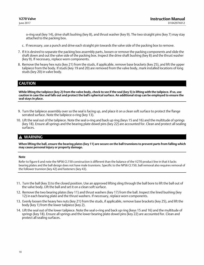
o‐ring seal (key 14), drive shaft bushing (key 8), and thrust washer (key 9). The two straight pins (key 7) may stayattached to the packing box.
c. If necessary, use a punch and drive each straight pin towards the valve side of the packing box to remove.
7. If it is desired to separate the packing box assembly parts, loosen or remove the packing components and slide theshaft down and out the valve side of the packing box. Inspect the drive shaft bushing (key 8) and the thrust washer(key 9). If necessary, replace worn components.
8. Remove the heavy hex nuts (key 21) from the studs, if applicable, remove base brackets (key 25), and lift the uppertailpiece from the body. If studs (key 19 and 20) are removed from the valve body, mark installed locations of longstuds (key 20) in valve body.
CAUTION
While lifting the tailpiece (key 2) from the valve body, check to see if the seal (key 5) is lifting with the tailpiece. If so, usecaution in case the seal falls out and protect the ball's spherical surface. An additional strap can be employed to ensure theseal stays in place.
9. Turn the tailpiece assembly over so the seal is facing up, and place it on a clean soft surface to protect the flangeserrated surface. Note the tailpiece o-ring (key 13).
10. Lift the seal out of the tailpiece. Note the seal o-ring and back up ring (keys 15 and 16) and the multitude of springs(key 18). Ensure all springs and the bearing plate dowel pins (key 22) are accounted for. Clean and protect all sealingsurfaces.
WARNING
When lifting the ball, ensure the bearing plates (key 11) are secure on the ball trunnions to prevent parts from falling whichmay cause personal injury or property damage.
Note
Refer to figure 6 and note the NPS6 CL150 construction is different than the balance of the V270 product line in that it lacksbearing plates and the ball design does not have male trunnions. Specific to the NPS6 CL150, ball removal also requires removal ofthe follower trunnion (key 42) and fasteners (key 43).
11. Turn the ball (key 3) to the closed position. Use an approved lifting sling through the ball bore to lift the ball out ofthe valve body. Lift the ball and set it on a clean soft surface.
12. Remove the two bearing plates (key 11) and thrust washers (key 17) from the ball. Inspect the lined bushing (key12) in each bearing plate and the thrust washers. If necessary, replace worn components.
13. Evenly loosen the heavy hex nuts (key 21) from the studs, if applicable, remove base brackets (key 25), and lift thebody (key 1) from the lower tailpiece (key 2).
14. Lift the seal out of the lower tailpiece. Note the seal o-ring and back up ring (keys 15 and 16) and the multitude ofsprings (key 18). Ensure all springs and the lower bearing plate dowel pins (key 22) are accounted for. Clean andprotect all sealing surfaces.

Instruction ManualD104297X012
V270 ValveJune 2017
11
Valve Assembly
Be sure to replace valve parts in the same position and orientation from which they were removed. Use the followingsteps to reassemble the valve.
Note
Clean and protect all sealing surfaces from damage while installing parts. Lubricate components when necessary as an aid forinstallation, and to help protect sealing surfaces.
Refer to figures 4, 5, and 6 that identify the V270 valve components by key number.
During assembly, visually inspect component surfaces that interface with an o-ring or seal for any damage that mayprevent proper sealing.
1. Place both tailpieces (key 2), flange end down on a clean soft surface with the seal assembly cavity facing up. Usecaution to protect the flange end serrated surfaces.
2. Lubricate the tailpiece counterbores where the seal will insert and inject lubricant into each of the spring holes.Install the seal springs (key 18).
3. On both seals (key 5), install the o-ring (key 15) and backup ring (key 16) in the correct orientation (see figures 5and 6).
4. Lubricate the seal o-rings and insert the seal assembly into the tailpiece counterbores. Maintain axial alignment ofthe two components as the seal assembly is pushed into place.
5. Lubricate and install the o‐rings (key 13) in both tailpieces.
a. For NPS 6 through NPS 12 constructions, one o-ring per tailpiece is required.
b. For NPS 14 through NPS 24 constructions, two o-rings per tailpiece are required.
6. Place the body (key 1) on an appropriate work surface.
7. If studs (keys 19 and 20) were removed from valve body during disassembly, apply anti-seize lubricant (Key 47) tothreaded stud holes. Apply anti-seize lubricant to the long studs (key 20), which are used to attach the basebrackets (key 25). Install the long studs first in the stud hole locations marked during disassembly. (Note: Basebrackets are not available for the NPS6 CL150 and NPS6 CL300 valve constructions.) Apply anti-seize compound tothe balance of studs (key 19) and install in the body.
8. Lubricate the tailpiece o-ring gland of the body and lower the tailpiece into place, guiding the male o-ring gland ofthe tailpiece within the female gland of the body. Take special care to prevent pinching of the o-ring. The tailpiecemust be oriented such that, the bearing plate dowel pin holes are in alignment and parallel with the body shaft boreaxis. Refer to figure 4 and note the tailpiece (key 2) orientation in relation to the body (key 1), bearing plates (key11), and dowel pins (key 22).
9. Apply anti-seize lubricant compound to the face and threads of the heavy hex nuts (key 21). If applicable, place thebase bracket (key 25) over the long studs. Install the heavy hex nuts on the studs by hand with the materialidentifier facing outwards. Use an appropriate torque device to apply the final torque specification (see table 3).
10. Lift and orient the assembly so the raised face of the tailpiece end connection flange is sitting on a clean, softsurface. Take special care to prevent damage to the raised face serrated surface. Install the bearing plate dowel pins(key 22) in the tailpiece. (Note: The dowel pins are not applicable to the NPS6 CL150, as this construction does notincorporate bearing plates.)
11. If necessary, install new bushings (key 12) in the bearing plates (key 11) by driving out the old and pressing in thenew.

Instruction ManualD104297X012
V270 ValveJune 2017
12
WARNING
When lifting the ball, ensure the bearing plates (key 11) are secure on the ball trunnions to prevent parts from falling whichmay cause personal injury or property damage.
12. Use an approved lifting sling through the ball bore to lift the ball (key 3).
a. Lubricate and install the thrust washers (key 17) and bearing plates on both ball trunnions.
b. Install the ball and bearing plate assembly into the body.
c. Guarantee the dowel pins (key 22) in the lower tailpiece have engaged the holes in the bearing plates and thatthe ball shaft interface geometry is aligned with the body shaft bore.
d. Note: Specific to the NPS 6 CL150 construction, lubricate and place the follower end thrust washer (key 17) in thefollower end bore of the ball then lubricate and press in the follower end bushing (key 12) prior to installing theball assembly into the body. See figure 6.
13. Insert the upper bearing plate dowel pins (key 22) into the intended holes and refer to steps 7 through 10 for theinstallation procedure of the upper studs, tailpiece, base bracket, and heavy hex nuts.
14. Insert the drive shaft (key 4) into the body shaft bore and engage the ball interface geometry. Slide the shaft thrustwasher (key 9) into place.
15. Install the drive shaft bushing (key 8) in the packing box from the end that engages the body. Lubricate and installthe o-ring (key 14) in the packing box housing.
16. After lubricating the body shaft bore and thrust washer (key 9), position the packing box housing assembly over thedrive shaft and slide into place ensuring the o-ring (key 14) properly engages the body shaft bore. For all V270constructions, other than the NPS6 CL150, skip to step 18.
17. Specific to the V270 NPS 6 CL150 construction, inject lubricant into the spring hole of the follower trunnion (key42) and install the grounding spring (key 40) by pressing firmly into place (see figure 6).
a. Lubricate and install the o-ring (key 41) in the gland of the follower trunnion.
b. Lubricate the body follower bore and install the follower trunnion assembly.
c. Apply anti-seize lubricant to the socket head cap screws (key 43) and tighten in a star pattern to 60 ft•lbf.
18. Apply anti-seize lubricant to the packing box housing socket head cap screws (key 10). Thread in all fasteners, butdo not tighten.
19. The packing box holes for the straight pins (key 7) were originally staked at the factory. Use a file to remove thedeformed material at the top of each pin hole to allow the pin to slide by with minimal interference. Lubricate thestraight pins (key 7) and drive each through the packing box housing and into the valve body. When properlyinstalled and bottomed out, the pin top surface will be slightly below the packing box top surface. Stake all pins inplace making sure the packing box housing material has been deformed within the bore to prevent the pins fromdisengaging.
20. Tighten the socket head cap screws (key 10) in a star pattern to the appropriate torque specification (see table 3).Reinstall the two plastic packing box plugs (key 39) into their respective jack bolt counterbores to preventenvironmental ingress.
21. Install the packing components as detailed in the Packing Maintenance section of this manual.
22. Install the valve shaft key (key 29), flat washer (key 30) and hex head bolt (key 31). The purpose of the washer andhex bolt is to prevent the key from migrating axially out of the keyway in-service.

Instruction ManualD104297X012
V270 ValveJune 2017
13
Table 3. Torque Values
VALVE SIZE, NPS CLASSVALVE BODY HEAVY HEX NUT TORQUE(1) PACKING BOX HOUSING SOCKET
HEAD CAP SCREW TORQUE(1)
N•m ft•lbf N•m ft•lbf
6
150 255 188 81 60
300 255 188 81 60
600 525 387 81 60
8
150 376 277 81 60
300 525 387 81 60
600 711 524 81 60
10
150 376 277 81 60
300 376 277 81 60
600 941 694 81 60
12
150 376 277 81 60
300 711 524 81 60
600 1267 934 81 60
14
150 525 387 81 60
300 525 387 81 60
600 1660 1224 81 60
16
150 525 387 81 60
300 711 524 81 60
600 2126 1568 81 60
20
150 711 524 81 60
300 1267 934 81 60
600 3305 2437 153 113
24
150 941 694 153 113
300 2777 2048 153 113
600 5782 4264 247 182
1. Fasteners must be lubricated to achieve proper preload
Actuator MountingUse the appropriate actuator instruction manual for mounting the actuator or changing the actuator position. Attachthe actuator mounting bracket to the valve packing box and tighten the mounting bracket fasteners as detailed intable 4.
Table 4. Required Actuator Mounting Bracket-to-Valve Bolt Torque
VALVE SIZE, NPSFASTENERSIZE INCH
SAE J429 GRADE 5/NCF3(1)
N•m ft•lbf
6¾-10 339 250
8
10⅞-10 508 375
12
14
1-1/4-8 1491 110016
20
24
1. Fasteners must be lubricated to achieve proper preload

Instruction ManualD104297X012
V270 ValveJune 2017
14
Determining Closed Position1. To confirm proper actuator adjustment visually check the position of the ball.
2. Adjust the actuator linkage or travel stops as described in the actuator instruction manual so that at the end ofstroke, the valve ball bore diameter in the full open (100%) position is in alignment and centered within theupstream and downstream valve seal inside diameters. The actuator linkage or travel stops should be adjusted sothat the full closed (0%) valve position is precisely 90 degrees from the visually verified 100% open position.
3. For reference, two parallel lines are machined on the actuator mounting end of the valve drive shaft (key 4). Thelines represent the orientation of the valve ball bore. The ball is in the closed position when the two lines areperpendicular to the pipeline bore.
Parts OrderingA serial number is assigned to each valve and stamped on the nameplate. Always refer to the valve serial number whencorresponding with your Emerson sales office or Local Business Partner regarding spare parts or technical information.When ordering replacement parts, also specify the part name and desired material.
WARNING
Use only genuine Fisher replacement parts. Components that are not supplied by Emerson Automation Solutions shouldnot, under any circumstances, be used in any Fisher valve, because they may void your warranty, might adversely affect theperformance of the valve, and could cause personal injury and property damage.
Parts KitsV270 Seal Spring kits
VALVESIZE,NPS
CLASSKEY
NUMBERQUANTITY
IN KITKIT PARTNUMBER
6 150-600 18 4 RV270SPX002
8-24 150-600 18 4 RV270SPX012

Instruction ManualD104297X012
V270 ValveJune 2017
15
Figure 4. V270 Exploded View
GE89572
NOTE:1. KEY NUMBERS 24, 26, 27, 39, 44, 45 AND 46 ARE NOT SHOWN
APPLY LUBRICANT

Instruction ManualD104297X012
V270 ValveJune 2017
16
Parts List
Note
Contact your Emerson sales office or Local Business Partner for Part
Ordering information.
Key Description
1 Valve BodyIf you need a valve body as a replacement part, order thevalve size, pressure rating, serial number, and desiredmaterial.
2 Tailpiece
3 Ball
4 Drive Shaft Assembly
5* Seal (2 req'd)
6 Packing Box Housing
7 Pin, Straight
8* Drive Shaft Bushing (1 req'd)
9* Thrust Washer (1 req'd)
10 Hex Socket Screw Cap
11 Bearing Plate
12* Lined Bushing (2 req'd)
13* O-Ring (2 req'd NPS 6-NPS 12; 4 req'd NPS 14-NPS 24)
14* O‐Ring (1 req'd)
15* O‐Ring (2 req'd)
16* Back up Ring (2 req'd)
Key Description
17* Thrust Washer (2 req'd)
18 Spring
19 Continuous Thread Stud - short
20 Continuous Thread Stud - long
21 Heavy Hex Nut
22 Dowel Pin
23 Hex Head Pipe Plug
24 NACE Label (not shown)
25 Base Bracket
26 Nameplate (not shown)
27 Drive Screw, for nameplate (not shown)
28 Hex Head Pipe Plug
29 Square Key
30 Flat Washer
31 Hex Head Screw Cap
32* Anti-Extrusion Ring (2 req'd)
33* Packing Set (1 req'd)
34 Packing Box Ring
35 Bolt Stud
36 Heavy Hex Nut
37 Packing Flange
38 Spring Pack Assembly
39* Packing Box Plug (not shown) (2 req'd)
40 Spring
41* O-Ring (1 req'd)
42 Follower Trunnion
43 Hex Socket Screw Cap
44 Clamp (not shown)
45 Ground Strap (not shown)
46 Round Head Screw Machine (not shown)
47 Lub Anti-seize/Lub-3
*Recommended spare parts

Instruction ManualD104297X012
V270 ValveJune 2017
17
Figure 5. Fisher NPS 6 CL300 through NPS 24 CL600 V270 Valve Assembly
NOTE: KEY NUMBERS 10, 23, 24, 26, 27, 28, 29, 35, 36, 39, 44 AND 45 ARE NOT SHOWN
GE89573
VIEW A
APPLY LUBRICANT
VIEW B
VIEW ASCALE 1:1
VIEW BSCALE 1:1

Instruction ManualD104297X012
V270 ValveJune 2017
18
Figure 6. Fisher NPS 6 CL150 V270 Valve Assembly
NOTE: KEY NUMBERS 10, 23, 24, 26, 27, 28, 29, 35, 36, 39, 44 AND 45 ARE NOT SHOWN
GE90204
VIEW A
APPLY LUBRICANT
VIEW BSCALE 4:1
VIEW C
VIEW ASCALE 4:1
VIEW CSCALE 2:1
VIEW B
Instruction ManualD104297X012
V270 ValveJune 2017
19

Instruction ManualD104297X012
V270 ValveJune 2017
20
Emerson Automation SolutionsMarshalltown, Iowa 50158 USASorocaba, 18087 BrazilCernay, 68700 FranceDubai, United Arab EmiratesSingapore 128461 Singapore
www.Fisher.com
The contents of this publication are presented for informational purposes only, and while every effort has been made to ensure their accuracy, they are notto be construed as warranties or guarantees, express or implied, regarding the products or services described herein or their use or applicability. All sales aregoverned by our terms and conditions, which are available upon request. We reserve the right to modify or improve the designs or specifications of suchproducts at any time without notice.
� 2017 Fisher Controls International LLC. All rights reserved.
Fisher and ENVIRO-SEAL are marks owned by one of the companies in the Emerson Automation Solutions business unit of Emerson Electric Co. EmersonAutomation Solutions, Emerson, and the Emerson logo are trademarks and service marks of Emerson Electric Co. All other marks are the property of theirrespective owners.
Neither Emerson, Emerson Automation Solutions, nor any of their affiliated entities assumes responsibility for the selection, use or maintenanceof any product. Responsibility for proper selection, use, and maintenance of any product remains solely with the purchaser and end user.