
First Vue Manual
87
FIRSTVUE, Fisher, Fisher-Rosemount and Managing the Process Better are marks owned by Fisher Controls International, Inc., or Fisher-Rosemount Systems, Inc. All other marks are the property of their respective owners. © 1996 Fisher Controls International, Inc.; All Rights Reserved Sizing
Transcript of First Vue Manual

FIRSTVUE, Fisher, Fisher-Rosemount and Managing theProcess Better are marks owned by Fisher ControlsInternational, Inc., or Fisher-Rosemount Systems, Inc.
All other marks are the property of their respective owners.
© 1996 Fisher Controls International, Inc.; All Rights Reserved
Sizing
1
Table of Contents
TABLE OF CONTENTS 1
CHAPTER 1: GETTING STARTED 4
How to Use this Manual 4
System Requirements 4
Installing FIRSTVUE™ 5
Removing FIRSTVUE™ 5
Opening FIRSTVUE™ 5
Closing FIRSTVUE™ and Saving Your Work 6
CHAPTER 2: FIRSTVUE™ OVERVIEW 7
Header Tab 8
Item List Tab 11
Sizing Tab 14
Pull Down Menus 17
Shortcuts and Hints 19
Program Overview Diagram 20
CHAPTER 3: SIZING AND SELECTION USING FIRSTVUETM 21
Sizing a Valve 21Entering and Selecting Process Conditions 22Using the Quick Valve Sizing Screen 23Using the Schematic Sizing Screen 24Using the Spreadsheet Sizing Dialog Box 25
Setting Sizing Preferences 28
Viewing Warnings 30
Viewing a Table of Noise versus Flow 30
Table of Contents
2
Selecting a Control Valve 32
Sizing an Actuator 36Sliding Stem Actuator Sizing 36Rotary Actuator Sizing 39
Checking the Stroking Speed of an Actuator 40
Sizing Monitors 42
Inserting Sizing Notes 44
CHAPTER 4: PROJECT MANAGEMENT USING FIRSTVUETM 45
Creating a New Project 46Adding, Changing, and Deleting User Information 46Filling in Project Information 48
Changing “Supplied to You By” Information 48
Opening an Existing Project 49
Modeling a New Project on an Existing Project 50
Working with Items 50Adding a New Item 51Copying an Item: 52Finding an Item 52Deleting an Item 52Adding, Changing, and Deleting Item Tags 53
Adding Project Notes 54
CHAPTER 5: IMPORT/EXPORT CAPABILITIES OF FIRSTVUETM 56
Using .MDB File Formats 56
Importing and Exporting .FFV File Formats 56To save a project in .FFV format: 56
Importing and Exporting .BSV File Formats 57
Importing and Exporting ISA File Formats 57Importing an ISA Specification File: 58Exporting an ISA Specification File: 59Creating or Editing an ISA Mapping File: 60
Exporting Dimensional Data 60
CHAPTER 6: CREATING SPECIFICATION SHEETS AND REPORTS 62
Creating a Spec Sheet 62
How to Use this Manual
FIRSTVUE™ User’s Guide 3
Printing Spec Sheets and Reports 64
FIRSTVUE™ Reports Examples 68Summary Report 69Sizing Calculation Report 70Fisher Spec Sheet 71ISA Spec Sheet 72Diffuser Spec Sheet 73
CHAPTER 7: ADDITIONAL HELP RESOURCES 74
Getting Help for the Active Screen or Field 74
Getting Help for a Selected Topic 74
Using Hypertext Links 78
Accessing On-line Data Tables 78
Accessing Express Help 79
INDEX 80
APPENDIX I 86
4
Chapter 1: Getting StartedWelcome to the FIRSTVUE™ application from Fisher-Rosemount. FIRSTVUE™ providescomplete control valve, actuator, and monitor sizing, and enables complete processequipment selection and specification sheet generation.
This User’s Guide describes the tasks you can perform with FIRSTVUE™ and gives anoverview of the program’s main functions and screens. Useful tips are also provided. You willfind additional information in the on-line Help contained in the program.
This chapter provides instructions for installing FIRSTVUE™ and using the manual. Itcontains the following sections:
• How to Use this Manual
• System Requirements
• Installing FIRSTVUE™
• Removing FIRSTVUE™
• Opening FIRSTVUE™
• Closing FIRSTVUE™ and Saving Your Work
How to Use this ManualThis manual contains an overview of FIRSTVUE™ functions, tasks, and screens. MostWindows users will find the information in this manual all they need to use the program.Additional help is available in FIRSTVUE™’s extensive on-line Help system.
This manual assumes that you are familiar with your computer and performing basic Windowstasks, such as using a mouse, selecting menu commands, and opening and saving files. Ifyou need help with any of these tasks, please consult your Windows documentation.
System RequirementsTo run FIRSTVUE™, you should have a personal computer 486 DX or higher.
FIRSTVUE™ is fully compatible with Windows 95 and 97. FIRSTVUE™ is able to run onWindows 3.11, but will not support Import ISA File, Export ISA File, and Edit ISA Map Filecommands found under the pull-down File menu.
Memory requirements are 8 Megabytes of RAM and 30 Megabytes of hard drive space.
Installing FIRSTVUE™
FIRSTVUE™ User’s Guide 5
Installing FIRSTVUE™Before you begin, we suggest making a backup copy of your FIRSTVUE™ disks, storing theoriginal disks in a safe place, and using your copies for installation.
To install FIRSTVUE™:
1. Start Windows and File Manager.
2. Insert the first setup disk in floppy drive A or B.
3. Choose Run from File Manager’s File Menu or Windows 95 Start button.
4. In the command line, type: A:SETUP (if you put the setup disk in drive A), or B:SETUP (ifyou put the disk in drive B).
5. Follow the instructions on your screen to complete installation.
The installer places FIRSTVUE™ in the FIRSTVUE™ directory on your C drive andinstalls MS DLLs into your Windows System Directory, if necessary. You can view acomplete history of files placed during installation in the INSTALL.LOG file on your harddrive.
Removing FIRSTVUE™To remove FIRSTVUE™:
1. Select the FIRSTVUE™ program from your Windows 95 Start button.
2. Select Uninstall.
3. Follow the instructions on your screen to uninstall FIRSTVUE™.
4. Another method of removing FIRSTVUE™ is deleting the program folder from MyComputer in a Windows 95 or Windows 3.11 operating system environment.
Opening FIRSTVUE™To open FIRSTVUE™:
1. Select the Start button on the Windows 95 or 97 workspace.
2. Select Programs.
3. Move the mouse to highlight the FIRSTVUE™ program.
4. Select the FIRSTVUE™ program item by depressing the left mouse button.
5. FIRSTVUE™ will launch and automatically take you to the header tab to begin working inthe software.
Closing FIRSTVUE™ and Saving Your WorkTo close FIRSTVUE™ and save your work:
1. Select Exit from the File Menu.
The following dialog box appears:
2. Click the Yes button to save your work.
6
Chapter 2: FIRSTVUE™ OverviewWelcome to the FIRSTVUE™ application from Fisher-Rosemount. FIRSTVUE™ softwareprovides customers complete control valve, actuator, and monitor sizing, as well as projectmanagement capability by enabling complete process equipment selection and specificationsheet generation.
This chapter will outline the basic functionality of FIRSTVUE™ and provide an overview of thedata and capabilities of the software. This section provides a brief roadmap to the capabilitiesof the software and useful field definitions to increase understanding of the software. Itcontains the following sections:
• Header Tab
• Item List Tab
• Sizing Tab
• Pull Down Menus
• Program Overview Diagram
Header Tab
FIRSTVUE™ User’s Guide 7
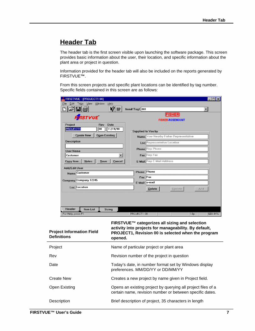
Header TabThe header tab is the first screen visible upon launching the software package. This screenprovides basic information about the user, their location, and specific information about theplant area or project in question.
Information provided for the header tab will also be included on the reports generated byFIRSTVUE™.
From this screen projects and specific plant locations can be identified by tag number.Specific fields contained in this screen are as follows:
Project Information FieldDefinitions
FIRSTVUE™ categorizes all sizing and selectionactivity into projects for manageability. By default,PROJECT1, Revision 00 is selected when the programopened.
Project Name of particular project or plant area
Rev Revision number of the project in question
Date Today’s date, in number format set by Windows displaypreferences. MM/DD/YY or DD/MM/YY
Create New Creates a new project by name given in Project field.
Open Existing Opens an existing project by querying all project files of acertain name, revision number or between specific dates.
Description Brief description of project, 35 characters in length
Chapter 2: FIRSTVUE™ Overview
8
User Name Pull-down selection of users that have been added toFIRSTVUE™. Information used for reports
Copy Item Allows copying one item from one project to anotherproject. Will ask for specific project to query to copy itemfrom.
Notes A free-form text note, these are useful for noting issues,questions for specific tag numbers, and progress in projectrelated work. They are not tied to a specific item number,but are visible from any item.
Save Saves the project to the Microsoft Access (.MDB) databasefile. This can take a while if you have many items in yourproject.
Cancel Cancels changes made before a save is done. It will notcancel changes made after the Save command isexecuted.
Supplied to You By The Supplied to You By data will typically already befilled in when you receive your software from your localrepresentative. If needed, both the logo and the datacan be modified by accessing the FIRSTVUE™directory or the FIRSTVUE.INI file, respectively. Forspecific information on this, see Chapter 4: ProjectManagement using FIRSTVUE™.
Name Representative name.
Loc Representative location/address.
Phone Representative phone number.
Fax Representative fax number.
E-mail Representative e-mail address.
Add/Edit User The Add/Edit User section allows the customer toinclude their name for reference on sizing andselection information and can be updated accordingly.
Name User first and last name
Company Company user works for
Loc Location of company, such as city, state.
Phone User’s phone number
Fax User’s fax number

Header Tab
FIRSTVUE™ User’s Guide 9
E-mail User’s e-mail address
Delete Deletes the selected user from the list of FIRSTVUE™ usernames
Update Update user information to reflect changes in phone,location, etc.
Add Add a new user to the list of user names.
Chapter 2: FIRSTVUE™ Overview
10
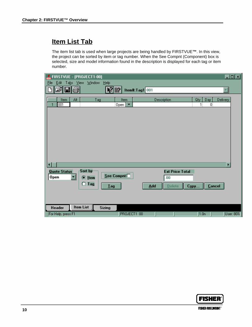
Item List TabThe item list tab is used when large projects are being handled by FIRSTVUE™. In this view,the project can be sorted by item or tag number. When the See Compnt (Component) box isselected, size and model information found in the description is displayed for each tag or itemnumber.
Item List Tab
FIRSTVUE™ User’s Guide 11
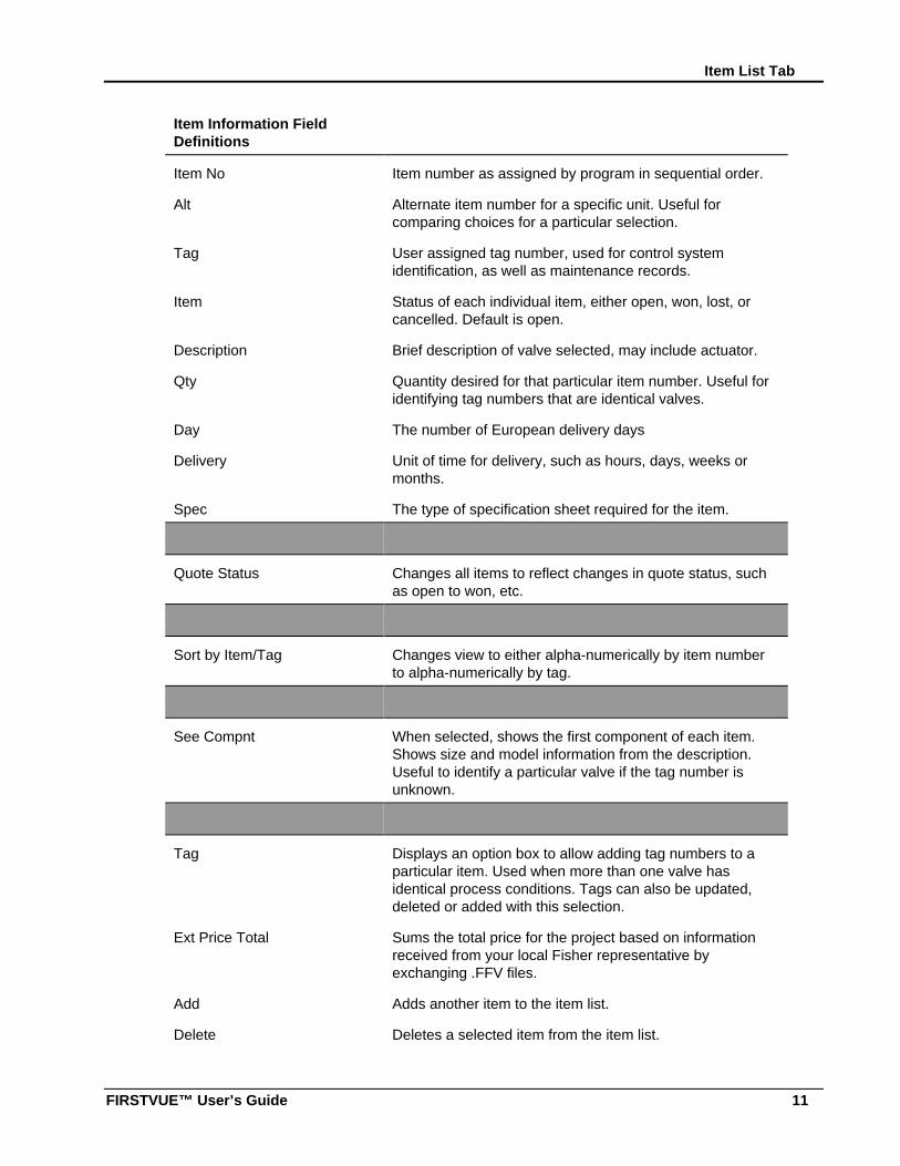
Item Information FieldDefinitions
Item No Item number as assigned by program in sequential order.
Alt Alternate item number for a specific unit. Useful forcomparing choices for a particular selection.
Tag User assigned tag number, used for control systemidentification, as well as maintenance records.
Item Status of each individual item, either open, won, lost, orcancelled. Default is open.
Description Brief description of valve selected, may include actuator.
Qty Quantity desired for that particular item number. Useful foridentifying tag numbers that are identical valves.
Day The number of European delivery days
Delivery Unit of time for delivery, such as hours, days, weeks ormonths.
Spec The type of specification sheet required for the item.
Quote Status Changes all items to reflect changes in quote status, suchas open to won, etc.
Sort by Item/Tag Changes view to either alpha-numerically by item numberto alpha-numerically by tag.
See Compnt When selected, shows the first component of each item.Shows size and model information from the description.Useful to identify a particular valve if the tag number isunknown.
Tag Displays an option box to allow adding tag numbers to aparticular item. Used when more than one valve hasidentical process conditions. Tags can also be updated,deleted or added with this selection.
Ext Price Total Sums the total price for the project based on informationreceived from your local Fisher representative byexchanging .FFV files.
Add Adds another item to the item list.
Delete Deletes a selected item from the item list.
Chapter 2: FIRSTVUE™ Overview
12
Copy Copies an item from another project.
Cancel Reverts order status and tags back to original values whentag was entered.
Information generated by a user can be easily transferred to your local Fisher representativeby saving the file using the Save As .FFV option. This electronic transferal of data allows yourFisher representative the ability to review all sizing and provide the user with a quotationbased on the information provided.
Sizing Tab
FIRSTVUE™ User’s Guide 13
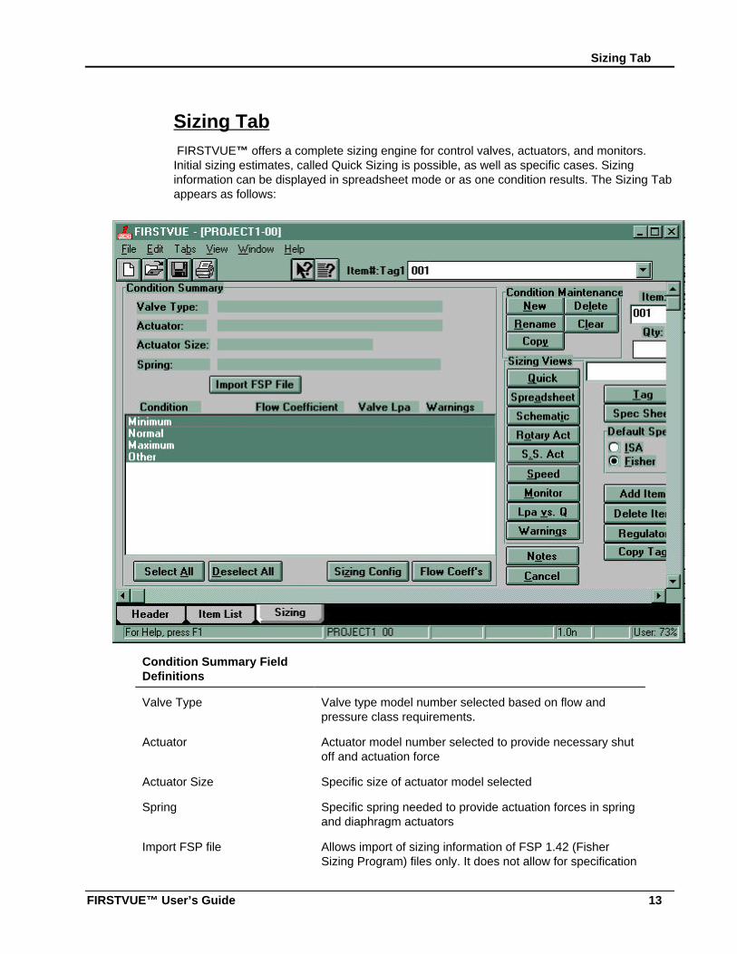
Sizing Tab FIRSTVUE™ offers a complete sizing engine for control valves, actuators, and monitors.Initial sizing estimates, called Quick Sizing is possible, as well as specific cases. Sizinginformation can be displayed in spreadsheet mode or as one condition results. The Sizing Tabappears as follows:
Condition Summary FieldDefinitions
Valve Type Valve type model number selected based on flow andpressure class requirements.
Actuator Actuator model number selected to provide necessary shutoff and actuation force
Actuator Size Specific size of actuator model selected
Spring Specific spring needed to provide actuation forces in springand diaphragm actuators
Import FSP file Allows import of sizing information of FSP 1.42 (FisherSizing Program) files only. It does not allow for specification
Chapter 2: FIRSTVUE™ Overview
14
sheet input from FSP 1.42.
Condition Up to ten conditions are possible, updated in the conditionmaintenance selection.
Flow Coefficient Flow coefficient calculated for each process condition topass required amount of fluid.
Valve LpA Noise estimate of fluid flow, pertains to gas sizing only.
Warnings Warnings issued by the sizing program to identify areas ofconcern, such as noise, cavitation, flashing, etc will bedisplayed as a Y if warnings are present. Press Warningsbutton to display any warnings present.
Select All Selects up to four process conditions for viewing in thespreadsheet mode.
Deselect All Removes selection of all process conditions to allow forspecific condition viewing in spreadsheet mode.
Sizing Config Allows selection of units of measure for pressure, gas flow,vapor flow, liquid flow, temperature, mass (gas), density,area, length, force, velocity, spring rate, viscosity, torqueand atmospheric pressure. Choices can also be made tohave either all English or Metric conventions.
Flow Coeffs Sizing information for Fisher control valves are displayed forthe selected process conditions. The user can selectbetween viewing all Cv data, or just those that pertain to theflow coefficients calculated.
Condition Maintenance
New Allows addition of another flow coefficient, up to tenmaximum.
Rename Renames highlighted condition to another name.
Copy Copies process conditions from one condition to another.
Delete Deletes the highlighted process condition.
Clear Clears either all information for highlighted conditions or justvalve, actuator, or monitor sizing information.
Sizing Views
Quick Basic sizing for liquids, ideal gas or vapor. Fluid informationof liquids and ideal gas based on published criticalpressure, vapor pressure and specific gravity. Useful toidentify range of flow coefficients required to pass flow.
Sizing Tab
FIRSTVUE™ User’s Guide 15
Spreadsheet Displays sizing information in spreadsheet format forhighlighted process conditions. Useful to identify flow rangerequired, as well as how changes in process conditionsaffect valve performance and requirements.
Schematic A visual method of valve sizing showing pressure drop, flowand fluid information schematically. Uses same sizingmethodology as the quick sizing approach.
Rotary Act Sizing of rotary actuator based on valve selected on samescreen. Calculates torque based on actuator orientation andpreferences.
S.S. Act Sizes sliding stem actuator to match selected control valve.Calculates forces required, and can also select actuatorsautomatically if needed.
Speed Calculates fill and relief times associated with actuatorselected. Identifies if quick release valves and otheraccessories are needed to provide fail-safe operation.
Monitor Calculates flow rates required for proper monitor operation.A monitor configuration, essentially two regulators piped invarious configurations, provides downstream overpressureprotection by controlling intermediate pressure between thetwo regulators.
LpA vs Q A tabular view of flow and corresponding noise levelpredictions. This view is useful in sizing diffusers or othermethods of controlling noise due to process flow.
Warnings A summary of all warnings associated with the processconditions highlighted.
Item Specific Information
Item Item number as assigned by program in sequential order.May be alpha-numeric and can be modified in this field.
Qty Quantity requested for the particular item.
Combo box Contains list of tags and item numbers.
Tag User assigned tag number, used for control systemidentification, as well as maintenance records.
Spec Sheet Specification sheet generated upon request based on thedefault spec selection, either ISA or Fisher based. Furtherselections can be made to reflect sliding stem, rotary,regulator, and diffuser choices.

Chapter 2: FIRSTVUE™ Overview
16
Default Spec (ISA/Fisher) Provides either an ISA or Fisher specification sheet,depending on user preference. Only used the first time thata spec sheet is entered for an item.
Add Item Adds an additional item to the project to the end of theproject.
Delete Item Deletes the selected item and requires confirmation of thedeletion.
Regulator Calculates regulator flow requirements in a tabular format.
Copy Tag Enables copying of flow sizing and selection data to anotheritem in the same project. The tag number must be modifiedbefore the OK portion of the command is enabled.
Notes Free form note field for actuator, valve sizing or strokingspeed information.
Cancel Returns screen information to information present when thesizing tab was first selected.
Pull Down MenusFIRSTVUE™ offers traditional Windows functionality by means of pull-down menusaccessible throughout all tabs and views as well as icons visible from every screen. Cutting,pasting and copying is possible within FIRSTVUE™, as well as jumping from one project toanother via the Window option.
File
New (Model On) Models a new project on a project in thedatabase. Existing project can be accessed byusing the query button.
New Project Opens a new project.
Open (Database) Allows user to open a project from the database.
Save to Database Saves project information to FIRSTVUE.MDBdatabase for use by FIRSTVUETM or Microsoft Accessor Excel applications.
Open FFV File Opens .FFV (First First Vue) file format.
Save to FFV File Saves project in .FFV (First First Vue) format to allowfor electronic quotation with local Fisherrepresentative or saving data to a network.
Pull Down Menus
FIRSTVUE™ User’s Guide 17
Delete from Database Allows deletion of project from database.
Close Project Closes current project and prompts for savingchanges.
Import ISA File Allows importation of .BSV (Bar separated value) fileformats from Intergraph’s IDMTM software.
Export ISA File Allows export of .BSV (Bar separated value) fileformats to Intergraph’s IDMTM software.
Edit ISA Map File Edits field ordering for ease of import/export flexibility.
Reports Allows additional report options, such as summary,sizing calculations, print warnings, and customheaders and footers for all or specific item numbers.
Print Setup Basic print setup information, such as printerselection, default printer, paper orientation, and paperlocation.
Exit Exits FIRSTVUE™ software package.
Edit
Cancel Changes Context specific cancellation of changes.
Cut Cut data, for moving purposes <Ctrl X>.
Copy Copy data, or use shortcut <Ctrl C>.
Paste Paste data, or use shortcut <Ctrl V>.
Delete Deletes data.
Tabs
Header Project header information <Ctrl 1>.
Item List Detailed information by item or tag number <Ctrl 2>.
Sizing Sizing information by item or tag number <Ctrl 3>.
View
Tool bars Toggles tool bar.
Status bar Toggles status bar.
Tab bar Toggles tab bar.
Chapter 2: FIRSTVUE™ Overview
18
Window Allows selection between open project files.
Help
Content Hypertext links to specific FIRSTVUE™ topics ofinterest.
Search Allows keyword searches for specific topics.
Using Help Provides help on Windows specific information
About FIRSTVUETM Provides software version number, as well ascopyright information.
Shortcuts and HintsSeveral shortcuts exist that can improve the efficiency of a user. Of particular note is the useof <Ctrl C> pushed simultaneously to copy and <Ctrl V> to paste.
Another hint that makes the sizing program easier to use is the use of the caret and yellowhighlighted fields visible on the spreadsheet sizing view. When the caret appears, thatindicates a field that can be changed from user supplied to calculated or system suppliedinformation. The yellow highlighting denotes fields that are calculated. For example, if flowrate is provided, Cv can be calculated. Also, a single click on a field can change theparameters associated with that value, such as toggling between pipe size and schedule andpipe diameter and thickness information.
The Import FSP button on the Sizing Tab only imports sizing data, not specification data fromFSP 1.42.
Notes are very useful to expand on explanation of product, location, needs, etc.
Use extreme caution when changing Atmospheric Pressure when sizing data has alreadybeen entered on one or more items. All sizing data can be lost if care is not taken in this area.To not lose sizing data, highlight the entire spreadsheet, hit <Ctrl C>, go to the Sizing Config,change the Atmospheric Pressure, and press OK, go to the sizing spreadsheet and hit <CtrlV>, Otherwise, you risk losing all calculated data due to the change in atmospheric pressure.This copying and re-pasting of spreadsheet information will enable atmospheric pressurechanges without having to re-key all valve related information. This process must be done onan item by item basis.
Program Overview Diagram
FIRSTVUE™ User’s Guide 19
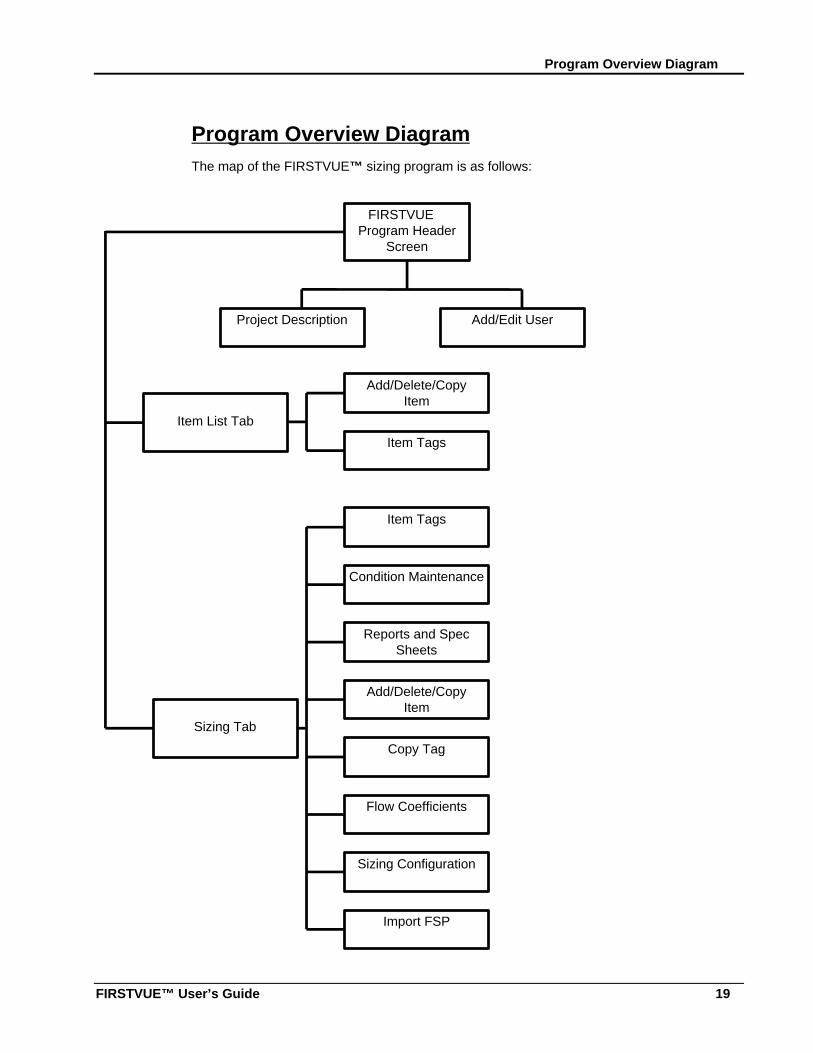
Program Overview DiagramThe map of the FIRSTVUE™ sizing program is as follows:
FIRSTVUEProgram Header
Screen
Item List Tab
Sizing Tab
Project Description Add/Edit User
Item Tags
Add/Delete/CopyItem
Item Tags
Condition Maintenance
Reports and SpecSheets
Add/Delete/CopyItem
Copy Tag
Flow Coefficients
Sizing Configuration
Import FSP
20
Chapter 3: Sizing and Selection UsingFIRSTVUE™In the last chapter, you saw an overview of the FIRSTVUE™ software. In this chapter, you willbegin to use the powerful sizing engine contained within FIRSTVUE™ for sizing valves,actuators and monitors. Selection of products and inserting sizing notes will also be covered.
This chapter contains the following sections:
• Sizing a Valve
Entering and Selecting Process Conditions
Using the Quick Valve Sizing Screen
Using the Schematic Sizing Screen
Using the Spreadsheet Sizing Dialog Box
• Selecting calculated fields
• Changing default field data
• Setting Sizing preferences
• Viewing Warnings
• Viewing a Table of Noise versus Flow
• Selecting a Control Valve
• Sizing an Actuator
Sliding Stem Actuator Sizing
Rotary Actuator Sizing
• Checking the Stroking Speed of an Actuator
• Sizing Monitors
• Inserting Sizing Notes
Sizing a ValveFIRSTVUE™ gives you several options for sizing a valve, depending on the amount ofinformation you have and the level of detailed calculations you need.
This section contains instructions for using the main sizing screens or options for valve sizing.It consists of the following sections:
• Entering and Selecting Process Conditions
Sizing a Valve
FIRSTVUE™ User’s Guide 21
• Using the Quick Valve Sizing Screen
• Using the Schematic Sizing Screen
• Using the Spreadsheet Sizing Dialog Box
Entering and Selecting Process Conditions
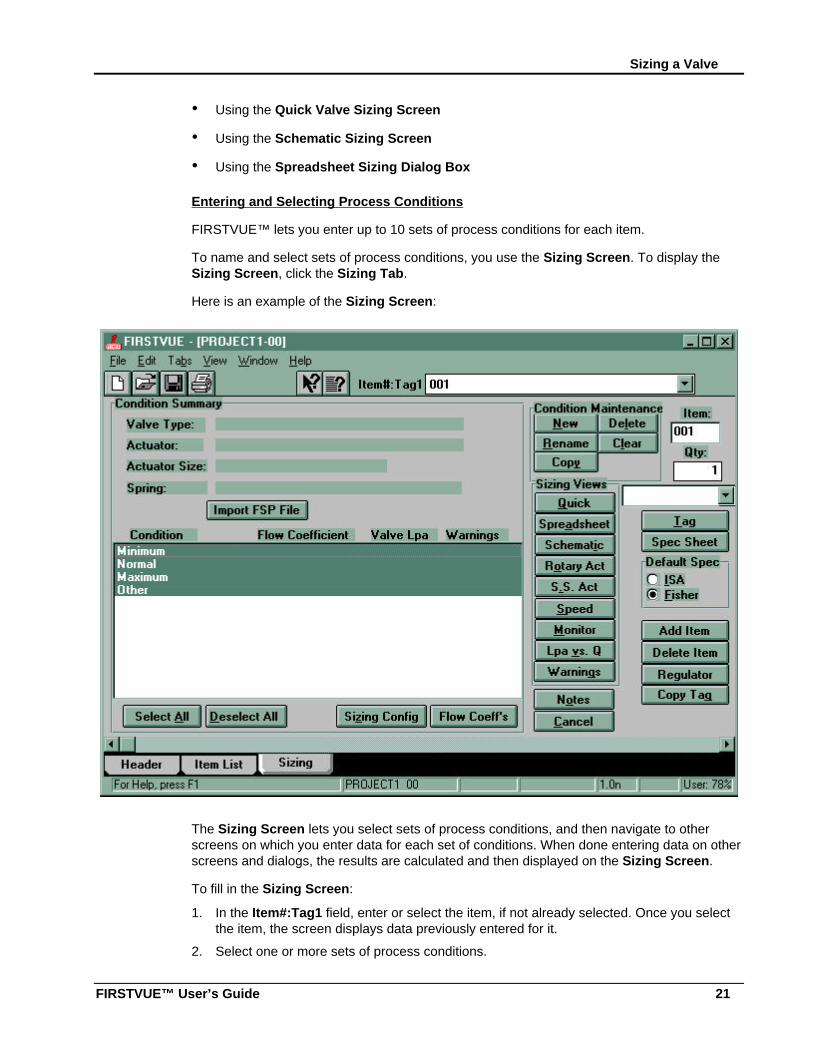
FIRSTVUE™ lets you enter up to 10 sets of process conditions for each item.
To name and select sets of process conditions, you use the Sizing Screen. To display theSizing Screen, click the Sizing Tab.
Here is an example of the Sizing Screen:
The Sizing Screen lets you select sets of process conditions, and then navigate to otherscreens on which you enter data for each set of conditions. When done entering data on otherscreens and dialogs, the results are calculated and then displayed on the Sizing Screen.
To fill in the Sizing Screen:
1. In the Item#:Tag1 field, enter or select the item, if not already selected. Once you selectthe item, the screen displays data previously entered for it.
2. Select one or more sets of process conditions.
Chapter 3: Sizing and Selection Using FIRSTVUE™
22
The spreadsheet area of the Condition Summary section displays process conditionsyou can select for your calculations. Minimum, Normal, Maximum, and Other are thedefault condition names.
You can add a new condition, rename, delete, copy, or clear all conditions by clicking onthe appropriate Condition Maintenance buttons.
Click a condition to select it or click the Select All or Deselect All buttons to select ordeselect all conditions respectively. A condition is highlighted when it is selected. You canselect up to 10 process conditions.
NOTE: You must select at least one condition to access other screens and dialogs.
Once you select a process condition, the Sizing Views buttons along the right side of thescreen become active, giving you access to other sizing screens.
FIRSTVUE™ offers three screens used in sizing valves:
• Quick Valve Sizing Screen—Lets you calculate the flow coefficient, for one condition.
• Schematic Sizing Screen—Lets you calculate the outlet pressure, flow, or flowcoefficient for one condition.
• Spreadsheet Sizing Dialog Box—Lets you do detailed calculations for multipleconditions at one time.
The following sections contain instructions for using the valve sizing screens.
Using the Quick Valve Sizing Screen
The Quick Valve Sizing Screen lets you enter basic information for one process condition,and then calculates and displays the flow coefficient for that condition. You can repeat thisprocedure for any number of process conditions.
To display this screen, click the Quick button on the Sizing Screen.
Sizing a Valve
FIRSTVUE™ User’s Guide 23
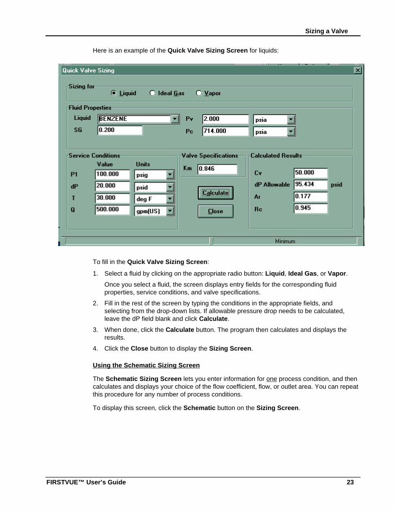
Here is an example of the Quick Valve Sizing Screen for liquids:
To fill in the Quick Valve Sizing Screen:
1. Select a fluid by clicking on the appropriate radio button: Liquid, Ideal Gas, or Vapor.
Once you select a fluid, the screen displays entry fields for the corresponding fluidproperties, service conditions, and valve specifications.
2. Fill in the rest of the screen by typing the conditions in the appropriate fields, andselecting from the drop-down lists. If allowable pressure drop needs to be calculated,leave the dP field blank and click Calculate.
3. When done, click the Calculate button. The program then calculates and displays theresults.
4. Click the Close button to display the Sizing Screen.
Using the Schematic Sizing Screen
The Schematic Sizing Screen lets you enter information for one process condition, and thencalculates and displays your choice of the flow coefficient, flow, or outlet area. You can repeatthis procedure for any number of process conditions.
To display this screen, click the Schematic button on the Sizing Screen.
Chapter 3: Sizing and Selection Using FIRSTVUE™
24
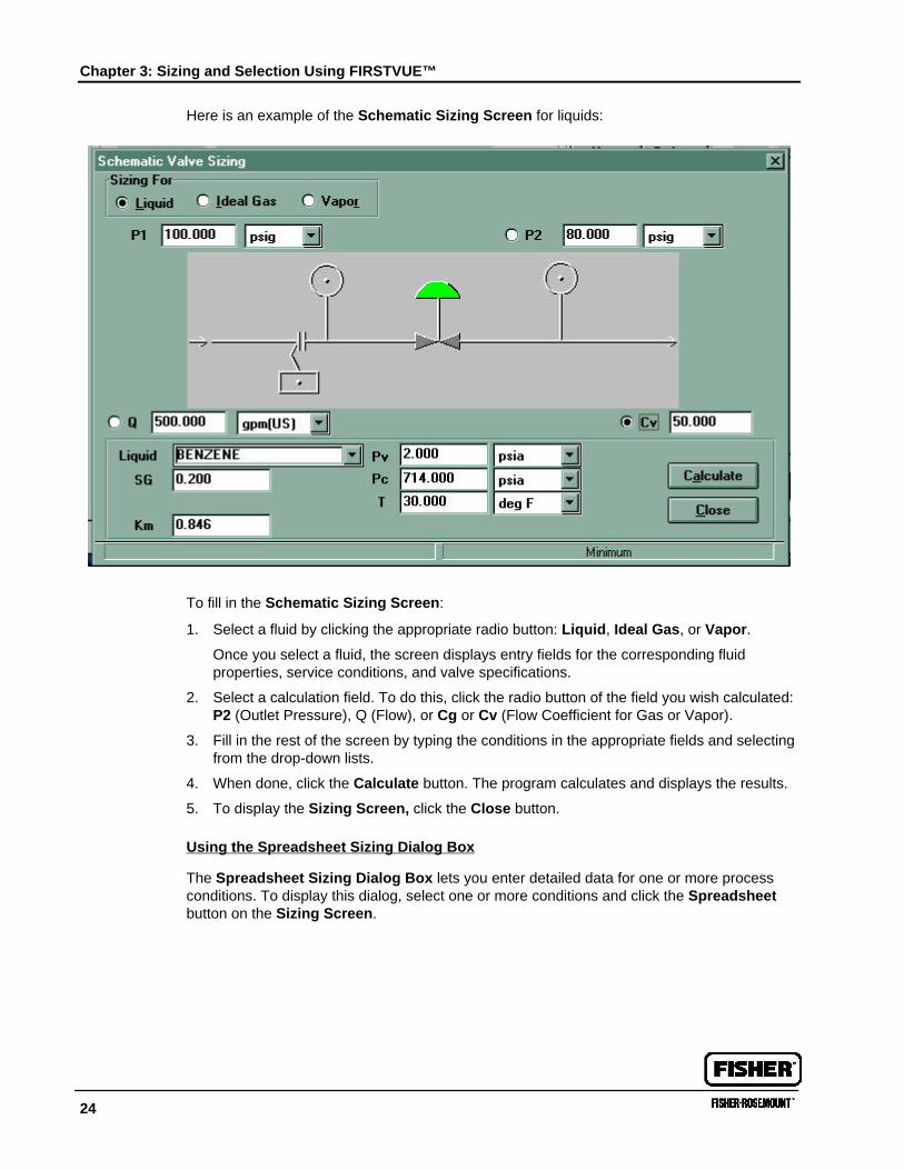
Here is an example of the Schematic Sizing Screen for liquids:
To fill in the Schematic Sizing Screen:
1. Select a fluid by clicking the appropriate radio button: Liquid, Ideal Gas, or Vapor.
Once you select a fluid, the screen displays entry fields for the corresponding fluidproperties, service conditions, and valve specifications.
2. Select a calculation field. To do this, click the radio button of the field you wish calculated:P2 (Outlet Pressure), Q (Flow), or Cg or Cv (Flow Coefficient for Gas or Vapor).
3. Fill in the rest of the screen by typing the conditions in the appropriate fields and selectingfrom the drop-down lists.
4. When done, click the Calculate button. The program calculates and displays the results.
5. To display the Sizing Screen, click the Close button.
Using the Spreadsheet Sizing Dialog Box
The Spreadsheet Sizing Dialog Box lets you enter detailed data for one or more processconditions. To display this dialog, select one or more conditions and click the Spreadsheetbutton on the Sizing Screen.
Sizing a Valve
FIRSTVUE™ User’s Guide 25
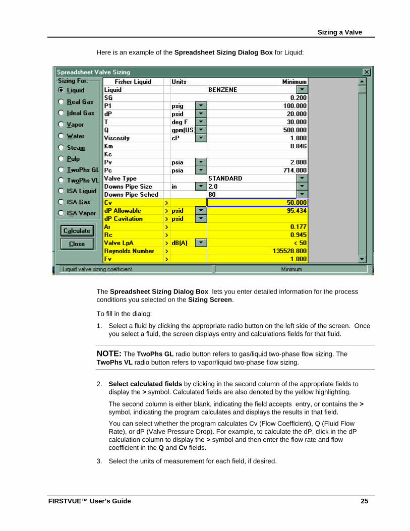
Here is an example of the Spreadsheet Sizing Dialog Box for Liquid:
The Spreadsheet Sizing Dialog Box lets you enter detailed information for the processconditions you selected on the Sizing Screen.
To fill in the dialog:
1. Select a fluid by clicking the appropriate radio button on the left side of the screen. Onceyou select a fluid, the screen displays entry and calculations fields for that fluid.
NOTE: The TwoPhs GL radio button refers to gas/liquid two-phase flow sizing. TheTwoPhs VL radio button refers to vapor/liquid two-phase flow sizing.
2. Select calculated fields by clicking in the second column of the appropriate fields todisplay the > symbol. Calculated fields are also denoted by the yellow highlighting.
The second column is either blank, indicating the field accepts entry, or contains the >symbol, indicating the program calculates and displays the results in that field.
You can select whether the program calculates Cv (Flow Coefficient), Q (Fluid FlowRate), or dP (Valve Pressure Drop). For example, to calculate the dP, click in the dPcalculation column to display the > symbol and then enter the flow rate and flowcoefficient in the Q and Cv fields.
3. Select the units of measurement for each field, if desired.
Chapter 3: Sizing and Selection Using FIRSTVUE™
26
The third column of the dialog displays the default units of measurement for each field.Changing default field data is done by selecting from the drop-down lists to overwritethe defaults.
NOTE: Downstream piping information can be toggled between Downs Pipe Size/DownsPipe Sched to Downs Pipe O.D./Downs Pipe Thick by simply clicking the mouse on one ofthose fields.
4. Enter the process data.
The fourth through thirteenth columns contain entry fields for each process condition youselected on the Sizing Screen. To fill in these fields, type or select from drop-down lists,depending on the field and fluid.
NOTE: The Spreadsheet Dialog Box displays four process conditions at a time. To enterinformation for additional process conditions, you must select them on the Sizing Screen andthen return to the Spreadsheet Dialog Box.
5. To view a table of noise versus flow for a process condition, click the LpA vs Q button forthat condition. You can include the table of noise versus flow in your spec sheets.
6. To calculate velocity, select the Upstream Area and Downstream Areas valve sizes byselecting from the drop-down lists, and then type data in the condition cells of thespreadsheet.
7. The Valve Incr. Velocity section lets you predict noise of the valve with velocity higherthan the standard guidelines allow. For assistance, contact your Fisher Salesperson.
8. For gas, vapor, or steam calculations that require additional noise attenuation
a. Scroll down the Spreadsheet view until the diffuser information section is visible.
b. Choose a diffuser for each set of conditions by selecting from the drop-down lists.
c. In the Diffuser Incr. Velocity section, in the Actual Outl. Area field, type the actualoutlet area in each cell, if necessary.
d. Click the Calculate button.
The program calculates and displays the noise levels.
The program may show different diffuser Cgs required for different processconditions. However, since a diffuser is a fixed device, it can have only one Cg.Therefore, you need to recalculate using the highest diffuser Cg displayed. To do this:
i. Click the second (calculation) column of the Diffuser Cg row to remove the >symbol.
ii. In each cell of the Diffuser Cg row, enter the highest diffuser Cg previouslycalculated.
iii. Click the Calculate button.
The program recalculates and displays the accurate noise levels for the diffuser Cg.
9. When done entering conditions, click the Calculate button. The program calculates anddisplays the results.
Setting Sizing Preferences
FIRSTVUE™ User’s Guide 27
To return to the Sizing Screen, click the Close button. The Sizing Screen displays theresults of your entries and calculations.
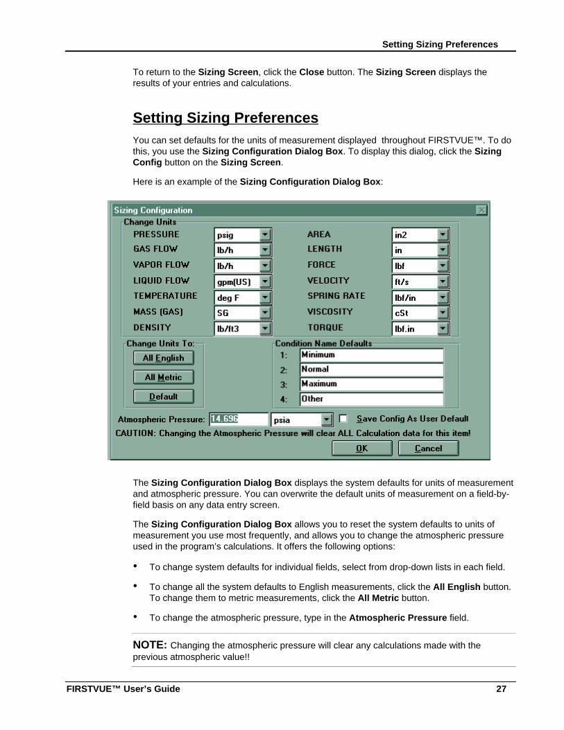
Setting Sizing PreferencesYou can set defaults for the units of measurement displayed throughout FIRSTVUE™. To dothis, you use the Sizing Configuration Dialog Box. To display this dialog, click the SizingConfig button on the Sizing Screen.
Here is an example of the Sizing Configuration Dialog Box:
The Sizing Configuration Dialog Box displays the system defaults for units of measurementand atmospheric pressure. You can overwrite the default units of measurement on a field-by-field basis on any data entry screen.
The Sizing Configuration Dialog Box allows you to reset the system defaults to units ofmeasurement you use most frequently, and allows you to change the atmospheric pressureused in the program’s calculations. It offers the following options:
• To change system defaults for individual fields, select from drop-down lists in each field.
• To change all the system defaults to English measurements, click the All English button.To change them to metric measurements, click the All Metric button.
• To change the atmospheric pressure, type in the Atmospheric Pressure field.
NOTE: Changing the atmospheric pressure will clear any calculations made with theprevious atmospheric value!!
Chapter 3: Sizing and Selection Using FIRSTVUE™
28
NOTE: To change the atmospheric pressure value for valves already sized without re-keying the process conditions, do the following: Highlight the specification sizing sheet dataand use <Ctrl C> to copy it into the clipboard memory. Then, change the atmosphericpressure, go back to the spreadsheet and paste, using <Ctrl V>, and then calculate.
• To erase your entries and revert to the previous system defaults, click the Default button.
• To save your entries, click the OK button. This creates new defaults for the program. Youcan still revert to the built-in system defaults by clicking on the Default button. Tooverwrite the built-in system defaults with your entries, click in the Save Units As UserDefault check box.
• When you click the OK button, the Sizing Screen appears.
Viewing WarningsFIRSTVUE™ issues warnings if a process condition exhibits cavitation, flashing, noise,excess velocity, or other conditions requiring attention. To view warnings, click the Warningsbutton on the Sizing Screen. The program then displays a series of dialog boxes showingwarnings for each process condition. The user can also select if the warnings issued byFIRSTVUE™ will be included on specification sheet reports.
Viewing a Table of Noise versus FlowYou can view a table of noise versus flow for each process condition in your case, and printthe table on your spec sheets. To do this, you use the LpA vs. Q Table. To display this table,click the LpA vs. Q button on either the Sizing Screen or the Sizing Spreadsheet. Bothmethods display the table.
Viewing a Table of Noise versus Flow
FIRSTVUE™ User’s Guide 29
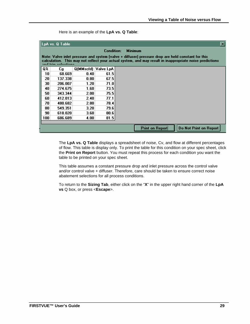
Here is an example of the LpA vs. Q Table:
The LpA vs. Q Table displays a spreadsheet of noise, Cv, and flow at different percentagesof flow. This table is display only. To print the table for this condition on your spec sheet, clickthe Print on Report button. You must repeat this process for each condition you want thetable to be printed on your spec sheet.
This table assumes a constant pressure drop and inlet pressure across the control valveand/or control valve + diffuser. Therefore, care should be taken to ensure correct noiseabatement selections for all process conditions.
To return to the Sizing Tab, either click on the “X” in the upper right hand corner of the LpAvs Q box, or press <Escape>.
Chapter 3: Sizing and Selection Using FIRSTVUE™
30
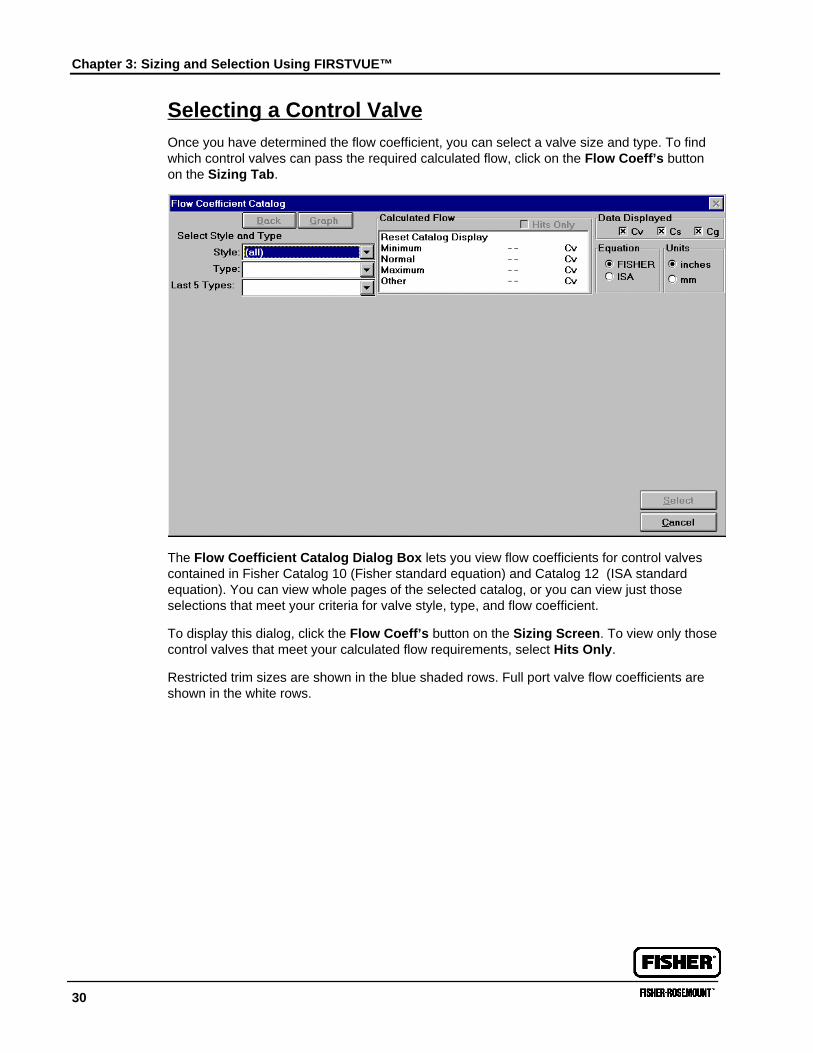
Selecting a Control ValveOnce you have determined the flow coefficient, you can select a valve size and type. To findwhich control valves can pass the required calculated flow, click on the Flow Coeff’s buttonon the Sizing Tab.
The Flow Coefficient Catalog Dialog Box lets you view flow coefficients for control valvescontained in Fisher Catalog 10 (Fisher standard equation) and Catalog 12 (ISA standardequation). You can view whole pages of the selected catalog, or you can view just thoseselections that meet your criteria for valve style, type, and flow coefficient.
To display this dialog, click the Flow Coeff’s button on the Sizing Screen. To view only thosecontrol valves that meet your calculated flow requirements, select Hits Only.
Restricted trim sizes are shown in the blue shaded rows. Full port valve flow coefficients areshown in the white rows.
Selecting a Control Valve
FIRSTVUE™ User’s Guide 31
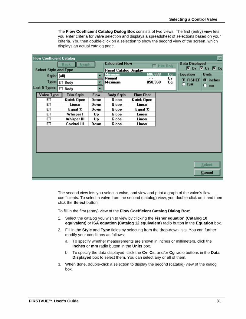
The Flow Coefficient Catalog Dialog Box consists of two views. The first (entry) view letsyou enter criteria for valve selection and displays a spreadsheet of selections based on yourcriteria. You then double-click on a selection to show the second view of the screen, whichdisplays an actual catalog page.
The second view lets you select a valve, and view and print a graph of the valve’s flowcoefficients. To select a valve from the second (catalog) view, you double-click on it and thenclick the Select button.
To fill in the first (entry) view of the Flow Coefficient Catalog Dialog Box:
1. Select the catalog you wish to view by clicking the Fisher equation (Catalog 10equivalent) or ISA equation (Catalog 12 equivalent) radio button in the Equation box.
2. Fill in the Style and Type fields by selecting from the drop-down lists. You can furthermodify your conditions as follows:
a. To specify whether measurements are shown in inches or millimeters, click theInches or mm radio button in the Units box.
b. To specify the data displayed, click the Cv, Cs, and/or Cg radio buttons in the DataDisplayed box to select them. You can select any or all of them.
3. When done, double-click a selection to display the second (catalog) view of the dialogbox.
Chapter 3: Sizing and Selection Using FIRSTVUE™
32
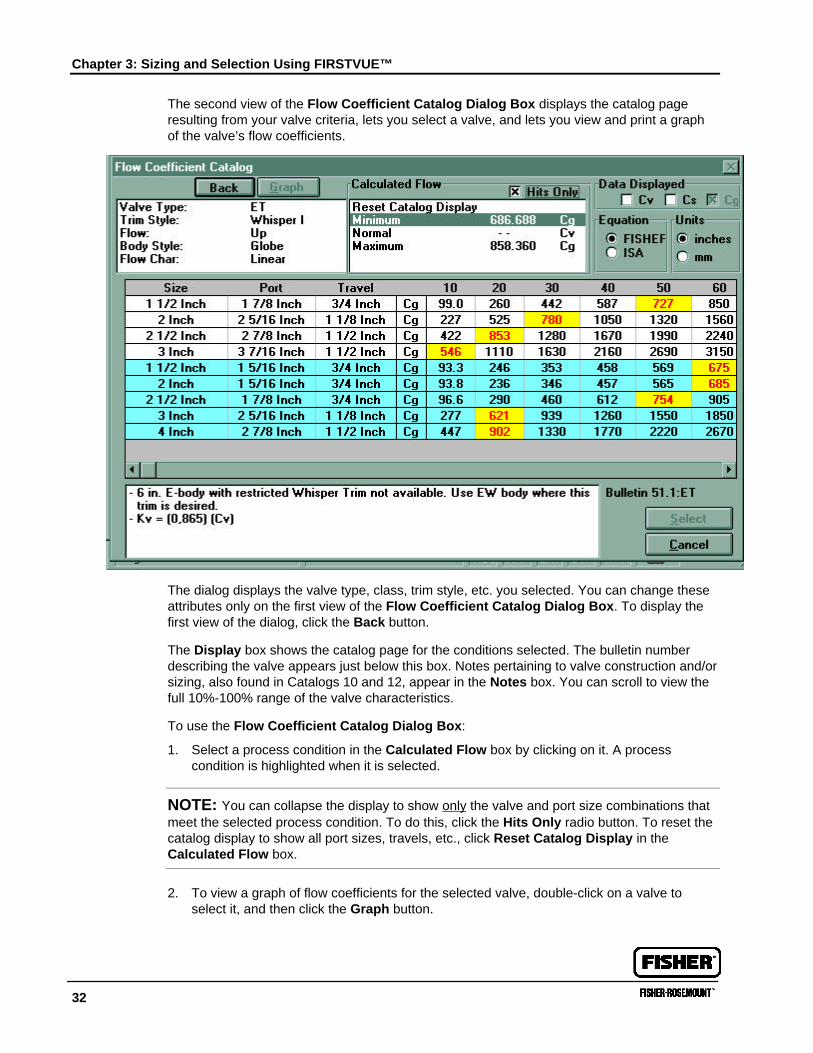
The second view of the Flow Coefficient Catalog Dialog Box displays the catalog pageresulting from your valve criteria, lets you select a valve, and lets you view and print a graphof the valve’s flow coefficients.
The dialog displays the valve type, class, trim style, etc. you selected. You can change theseattributes only on the first view of the Flow Coefficient Catalog Dialog Box. To display thefirst view of the dialog, click the Back button.
The Display box shows the catalog page for the conditions selected. The bulletin numberdescribing the valve appears just below this box. Notes pertaining to valve construction and/orsizing, also found in Catalogs 10 and 12, appear in the Notes box. You can scroll to view thefull 10%-100% range of the valve characteristics.
To use the Flow Coefficient Catalog Dialog Box:
1. Select a process condition in the Calculated Flow box by clicking on it. A processcondition is highlighted when it is selected.
NOTE: You can collapse the display to show only the valve and port size combinations thatmeet the selected process condition. To do this, click the Hits Only radio button. To reset thecatalog display to show all port sizes, travels, etc., click Reset Catalog Display in theCalculated Flow box.
2. To view a graph of flow coefficients for the selected valve, double-click on a valve toselect it, and then click the Graph button.
Selecting a Control Valve
FIRSTVUE™ User’s Guide 33
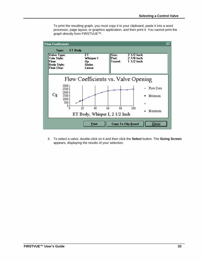
To print the resulting graph, you must copy it to your clipboard, paste it into a wordprocessor, page layout, or graphics application, and then print it. You cannot print thegraph directly from FIRSTVUE™.
3. To select a valve, double-click on it and then click the Select button. The Sizing Screenappears, displaying the results of your selection.
Chapter 3: Sizing and Selection Using FIRSTVUE™
34
Sizing an ActuatorSizing of both sliding stem and rotary actuators is possible with FIRSTVUE™.
Sliding Stem Actuator Sizing
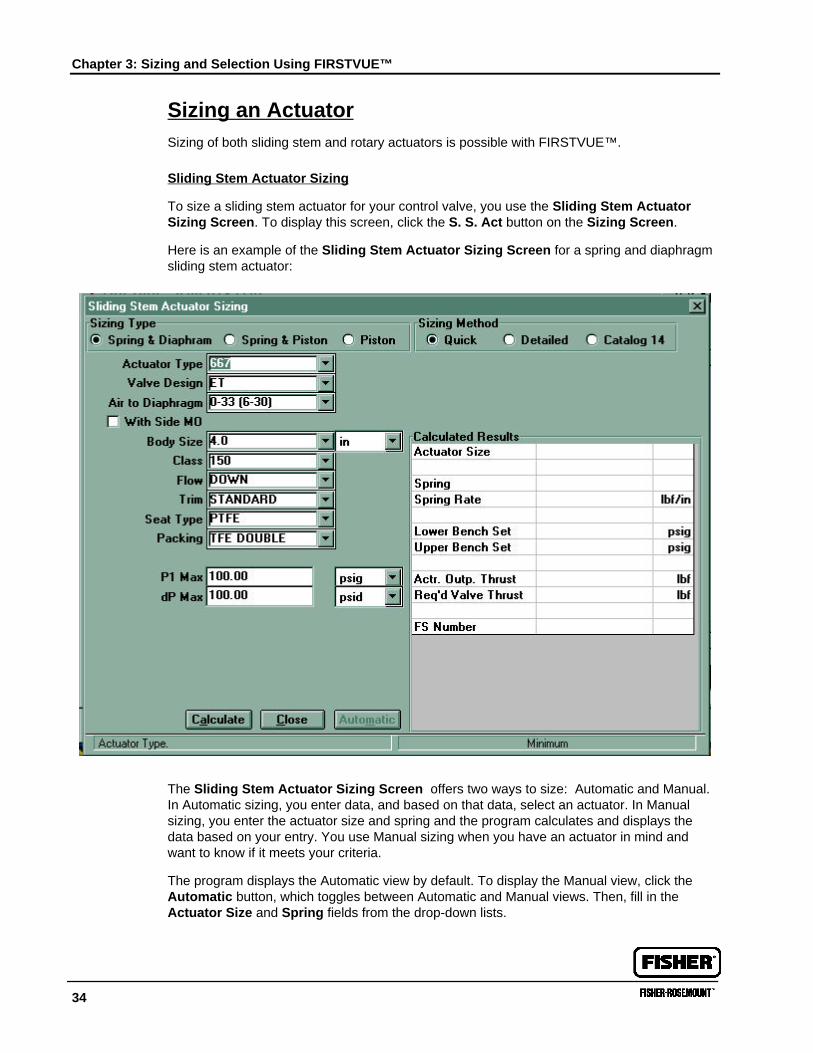
To size a sliding stem actuator for your control valve, you use the Sliding Stem ActuatorSizing Screen. To display this screen, click the S. S. Act button on the Sizing Screen.
Here is an example of the Sliding Stem Actuator Sizing Screen for a spring and diaphragmsliding stem actuator:
The Sliding Stem Actuator Sizing Screen offers two ways to size: Automatic and Manual.In Automatic sizing, you enter data, and based on that data, select an actuator. In Manualsizing, you enter the actuator size and spring and the program calculates and displays thedata based on your entry. You use Manual sizing when you have an actuator in mind andwant to know if it meets your criteria.
The program displays the Automatic view by default. To display the Manual view, click theAutomatic button, which toggles between Automatic and Manual views. Then, fill in theActuator Size and Spring fields from the drop-down lists.
Sizing an Actuator
FIRSTVUE™ User’s Guide 35
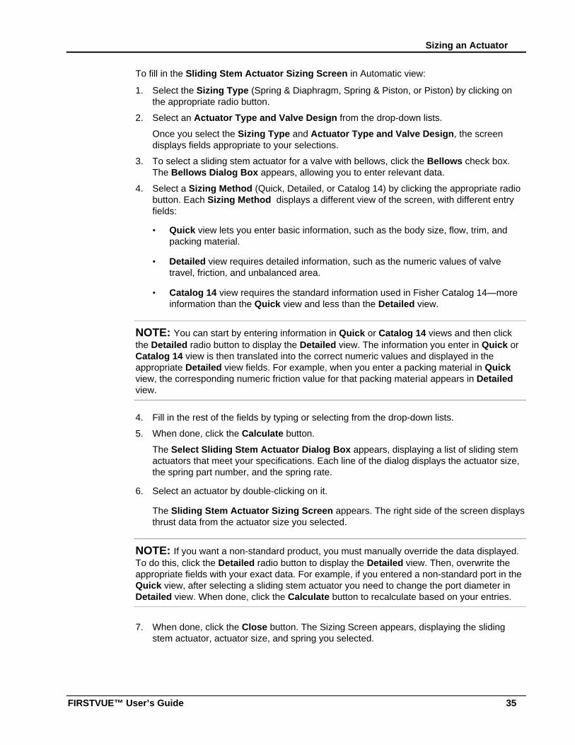
To fill in the Sliding Stem Actuator Sizing Screen in Automatic view:
1. Select the Sizing Type (Spring & Diaphragm, Spring & Piston, or Piston) by clicking onthe appropriate radio button.
2. Select an Actuator Type and Valve Design from the drop-down lists.
Once you select the Sizing Type and Actuator Type and Valve Design, the screendisplays fields appropriate to your selections.
3. To select a sliding stem actuator for a valve with bellows, click the Bellows check box.The Bellows Dialog Box appears, allowing you to enter relevant data.
4. Select a Sizing Method (Quick, Detailed, or Catalog 14) by clicking the appropriate radiobutton. Each Sizing Method displays a different view of the screen, with different entryfields:
• Quick view lets you enter basic information, such as the body size, flow, trim, andpacking material.
• Detailed view requires detailed information, such as the numeric values of valvetravel, friction, and unbalanced area.
• Catalog 14 view requires the standard information used in Fisher Catalog 14—moreinformation than the Quick view and less than the Detailed view.
NOTE: You can start by entering information in Quick or Catalog 14 views and then clickthe Detailed radio button to display the Detailed view. The information you enter in Quick orCatalog 14 view is then translated into the correct numeric values and displayed in theappropriate Detailed view fields. For example, when you enter a packing material in Quickview, the corresponding numeric friction value for that packing material appears in Detailedview.
4. Fill in the rest of the fields by typing or selecting from the drop-down lists.
5. When done, click the Calculate button.
The Select Sliding Stem Actuator Dialog Box appears, displaying a list of sliding stemactuators that meet your specifications. Each line of the dialog displays the actuator size,the spring part number, and the spring rate.
6. Select an actuator by double-clicking on it.
The Sliding Stem Actuator Sizing Screen appears. The right side of the screen displaysthrust data from the actuator size you selected.
NOTE: If you want a non-standard product, you must manually override the data displayed.To do this, click the Detailed radio button to display the Detailed view. Then, overwrite theappropriate fields with your exact data. For example, if you entered a non-standard port in theQuick view, after selecting a sliding stem actuator you need to change the port diameter inDetailed view. When done, click the Calculate button to recalculate based on your entries.
7. When done, click the Close button. The Sizing Screen appears, displaying the slidingstem actuator, actuator size, and spring you selected.
Chapter 3: Sizing and Selection Using FIRSTVUE™
36
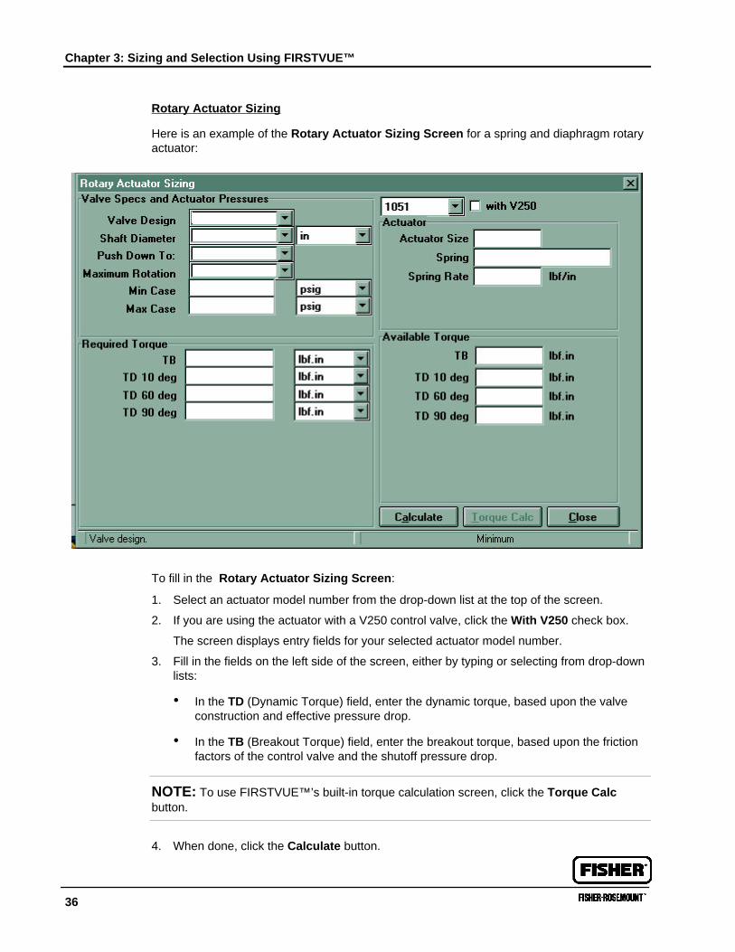
Rotary Actuator Sizing
Here is an example of the Rotary Actuator Sizing Screen for a spring and diaphragm rotaryactuator:
To fill in the Rotary Actuator Sizing Screen:
1. Select an actuator model number from the drop-down list at the top of the screen.
2. If you are using the actuator with a V250 control valve, click the With V250 check box.
The screen displays entry fields for your selected actuator model number.
3. Fill in the fields on the left side of the screen, either by typing or selecting from drop-downlists:
• In the TD (Dynamic Torque) field, enter the dynamic torque, based upon the valveconstruction and effective pressure drop.
• In the TB (Breakout Torque) field, enter the breakout torque, based upon the frictionfactors of the control valve and the shutoff pressure drop.
NOTE: To use FIRSTVUE™’s built-in torque calculation screen, click the Torque Calcbutton.
4. When done, click the Calculate button.
Checking the Stroking Speed of an Actuator
FIRSTVUE™ User’s Guide 37
The Select Rotary Actuator Dialog Box appears, displaying a list of rotary actuatorsthat meet your specifications. Each line of the dialog displays the actuator size, the springpart number, and the spring rate. For 1051 series, the screen also displays the seatnumber.
5. Select an actuator by double-clicking on it.
The Rotary Actuator Sizing Screen reappears. The right side of the screen is filled inwith torque data from the actuator size you selected.
6. Compare the required torque entered on the left side of the screen with the availabletorque on the right side of the screen to be sure the actuator size you selected hasadequate capacity. If not, click the Calculate button to display the Select RotaryActuator Dialog Box and select a different actuator.
7. When done, to display the Sizing Screen, click the Close button. The Sizing Screendisplays the actuator, actuator size, and spring you selected.
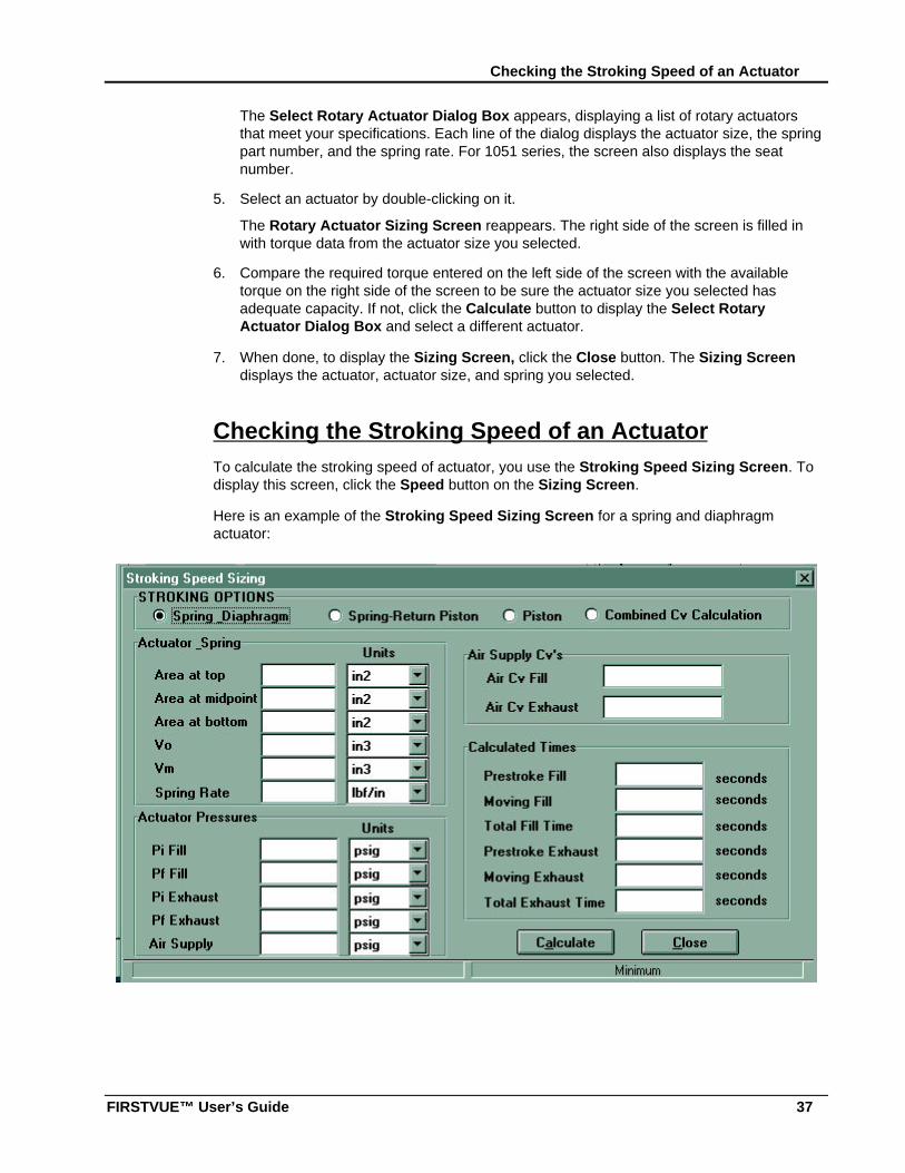
Checking the Stroking Speed of an ActuatorTo calculate the stroking speed of actuator, you use the Stroking Speed Sizing Screen. Todisplay this screen, click the Speed button on the Sizing Screen.
Here is an example of the Stroking Speed Sizing Screen for a spring and diaphragmactuator:
Chapter 3: Sizing and Selection Using FIRSTVUE™
38
To fill in the Stroking Speed Sizing Screen:
1. Select a stroking option by clicking on the appropriate radio button: Spring Diaphragm,Spring-Return Piston, or Piston.
Once you select an option, the screen displays data entry fields for that option.
2. Fill in the fields on the left side of the screen by typing or selecting from drop-down lists.
NOTE: You must enter accurate figures for the initial and final filling stroking pressures (PiFill and Pf Fill fields), and initial and final exhausting stroking pressures (Pi Exhaust and PfExhaust fields). For equations used to calculate these figures, see the on-line Help topic,“Valve Sizing Supplemental Information.”
3. Fill in the Air Cv Fill field with the combined flow coefficient of the filling air supplyapparatus.
You need to enter the combined Cvs of each apparatus in the air supply line to theactuator. To calculate the combined Cvs:
a. Click the Combined Cv Calculation radio button to display a Cv calculationworksheet.
b. Enter the Cv for each apparatus.
c. Click the Calculate button.
The Calculated Results Dialog Box appears, displaying the combined Cv. You needto make a note of this figure or copy it to the clipboard; the program does not copy itautomatically to the proper field.
d. When done, click the appropriate radio button (Spring Diaphragm, Spring-ReturnPiston, or Piston) to display the screen you wish.
e. Type the combined Cv in the Air Cv Fill field.
4. Fill in the Air Cv Exhaust field with the combined flow coefficient for the exhaustapparatus. To calculate the combined Cv for the air exhaust apparatus, repeat steps 3a—3e, using Cv’s for each apparatus in the exhaust line.
5. Click the Calculate button. The calculated results appear on the right side of the screen.
6. When done, to display the Sizing Screen, click the Close button.
Sizing MonitorsFIRSTVUE™ lets you calculate the intermediate pressure, flow coefficients, and flow capacityfor monitoring systems. This chapter contains instructions for using FIRSTVUE™ for yourmonitor sizing calculations.
To size monitors, you use the Monitor Sizing Screen. To display this screen, you click theMonitor button on the Sizing Screen.
Sizing Monitors
FIRSTVUE™ User’s Guide 39
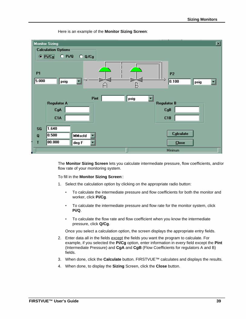
Here is an example of the Monitor Sizing Screen:
The Monitor Sizing Screen lets you calculate intermediate pressure, flow coefficients, and/orflow rate of your monitoring system.
To fill in the Monitor Sizing Screen::
1. Select the calculation option by clicking on the appropriate radio button:
• To calculate the intermediate pressure and flow coefficients for both the monitor andworker, click Pi/Cg.
• To calculate the intermediate pressure and flow rate for the monitor system, clickPi/Q.
• To calculate the flow rate and flow coefficient when you know the intermediatepressure, click Q/Cg.
Once you select a calculation option, the screen displays the appropriate entry fields.
2. Enter data all in the fields except the fields you want the program to calculate. Forexample, if you selected the Pi/Cg option, enter information in every field except the Pint(Intermediate Pressure) and CgA and CgB (Flow Coefficients for regulators A and B)fields.
3. When done, click the Calculate button. FIRSTVUE™ calculates and displays the results.
4. When done, to display the Sizing Screen, click the Close button.
Chapter 3: Sizing and Selection Using FIRSTVUE™
40
Inserting Sizing NotesFIRSTVUE™ allows the user the ability to add notes to each individual item for clarificationand quotation purposes. These notes are added to the Valve Sizing Report, Actuator SizingReport, and the Stroking Speed Sizing Report. Only one note is allowed for each item.
To add sizing notes:
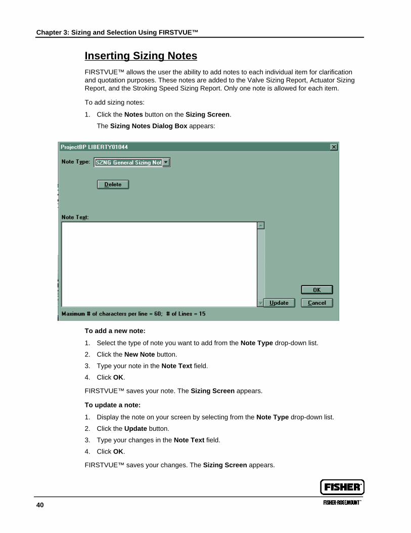
1. Click the Notes button on the Sizing Screen.
The Sizing Notes Dialog Box appears:
To add a new note:
1. Select the type of note you want to add from the Note Type drop-down list.
2. Click the New Note button.
3. Type your note in the Note Text field.
4. Click OK.
FIRSTVUE™ saves your note. The Sizing Screen appears.
To update a note:
1. Display the note on your screen by selecting from the Note Type drop-down list.
2. Click the Update button.
3. Type your changes in the Note Text field.
4. Click OK.
FIRSTVUE™ saves your changes. The Sizing Screen appears.
41
Chapter 4: Project Management UsingFIRSTVUE™We call each FIRSTVUE™ record a Project. A Project can contain one or more items—valves, actuators, monitors, etc. Your Fisher Representative uses the data files, spec sheets,and reports from FIRSTVUE™ Projects, saved in .FFV file formats, to provide you withaccurate and timely price quotations.
When you create a new Project, you assign a Project number and include the name andaddress of your company contact and other information identifying the Project. When yousave a Project, the program stores it in the MS Access database within the program. Whenyou open the Project, the program loads it and displays its data in FIRSTVUE™ screens.
This chapter contains instructions for working with projects and items. It contains the followingsections:
• Creating a New Project
Adding, Changing, and Deleting User Information
Filling in Project Information
• Changing “Supplied to You By” Information
• Opening an Existing Project
• Modeling a New Project on an Existing Project
• Working with Items
Adding a New Item
Copying an Item
Finding an Item
Deleting an Item
Adding, Changing, and Deleting Item Tags
Chapter 4: Project Management Using FIRSTVUE™
42
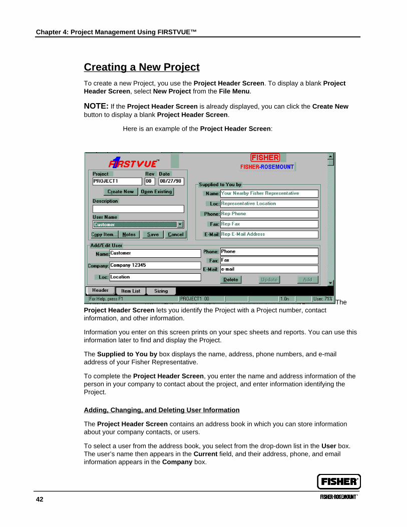
Creating a New ProjectTo create a new Project, you use the Project Header Screen. To display a blank ProjectHeader Screen, select New Project from the File Menu.
NOTE: If the Project Header Screen is already displayed, you can click the Create Newbutton to display a blank Project Header Screen.
Here is an example of the Project Header Screen:
TheProject Header Screen lets you identify the Project with a Project number, contactinformation, and other information.
Information you enter on this screen prints on your spec sheets and reports. You can use thisinformation later to find and display the Project.
The Supplied to You by box displays the name, address, phone numbers, and e-mailaddress of your Fisher Representative.
To complete the Project Header Screen, you enter the name and address information of theperson in your company to contact about the project, and enter information identifying theProject.
Adding, Changing, and Deleting User Information
The Project Header Screen contains an address book in which you can store informationabout your company contacts, or users.
To select a user from the address book, you select from the drop-down list in the User box.The user’s name then appears in the Current field, and their address, phone, and emailinformation appears in the Company box.
Creating a New Project
FIRSTVUE™ User’s Guide 43
The following sections describe how to add, change, and delete users from the address book.
Adding a User
To add a user to the address book:
1. In the Current field, type the contact’s name.
2. In the Company box, enter your company or division name, location, phone, fax, andemail address in the appropriate fields.
3. Click the Add button in the User box.
The program saves the contact information.
Updating User Information
To change or update information about a user:
1. Select the user from the drop-down list.
2. Type over the information you wish to change.
3. Click the Update button in the User box.
The program saves your changes.
Deleting a User
To delete a user from the address book:
1. Select the user from the drop-down list.
2. Click the Delete button in the User box.
The program deletes the user.
Chapter 4: Project Management Using FIRSTVUE™
44
Filling in Project Information
To fill in Project information:
1. In the Project box, type the Project number. You can assign any combination of 10numbers or characters to identify the Project.
NOTE: Project numbers must be unique. If you assign a duplicate Project number, when yousave the new Project the program will overwrite the ‘old’ Project with your new information.
2. In the Rev field, type the revision ID. You can type two numbers or characters to identifythe revision.
3. Fill in the Date field as follows:
• Type the date in the MM/DD/YY format. For example, to enter November 26, 1998,type: 11/26/98. The program will default to the date format preferences established inWindows’ settings, making DD/MM/YY formats possible.
— OR —
• Double-click on the Date field to display the Calendar Dialog Box. Then, use yourmouse to select a year, month, and date.
4. In the Description field, type a brief description of the Project.
5. When done, to save the Project:
• Select Save from the File Menu. — OR —
• Press Control + S. — OR —
• Click the Save button.
Changing “Supplied to You By” InformationThe Supplied to You By data will typically already be filled in when you receive the softwarefrom your local Fisher representative. If modifications are needed, make them in theFIRSTVUE.INI file found in c:\Windows\.
Once FIRSTVUE™ is installed, the FIRSTVUE.INI file is copied to the Windows directory.“Supplied to You By” data can be edited in the FIRSTVUE.INI file located in c:\Windows\. TheFIRSTVUE.INI file in the FIRSTVUE™ directory is detached from the working copy ofFIRSTVUE™ - revisions to it will only take effect if they are made before installation.
Opening an Existing ProjectTo open an existing Project, you use the Project Search Dialog Box. To display this dialog:
1. Select Open from the File Menu. — OR —
Click the Open Existing button on the Project Header Screen.
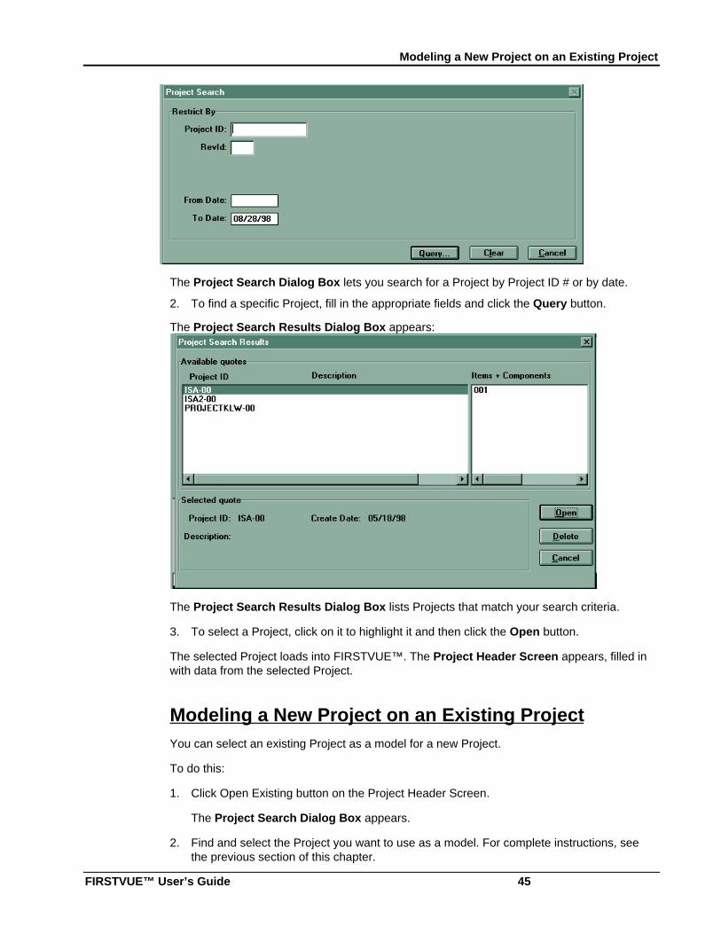
The Project Search Dialog Box appears:
Modeling a New Project on an Existing Project
FIRSTVUE™ User’s Guide 45
The Project Search Dialog Box lets you search for a Project by Project ID # or by date.
2. To find a specific Project, fill in the appropriate fields and click the Query button.
The Project Search Results Dialog Box appears:
The Project Search Results Dialog Box lists Projects that match your search criteria.
3. To select a Project, click on it to highlight it and then click the Open button.
The selected Project loads into FIRSTVUE™. The Project Header Screen appears, filled inwith data from the selected Project.
Modeling a New Project on an Existing ProjectYou can select an existing Project as a model for a new Project.
To do this:
1. Click Open Existing button on the Project Header Screen.
The Project Search Dialog Box appears.
2. Find and select the Project you want to use as a model. For complete instructions, seethe previous section of this chapter.
Chapter 4: Project Management Using FIRSTVUE™
46
3. Once you select the Project, the Project Header Screen appears, filled in with data fromthe selected project.
4. Type a new Project ID # in the Project box.
Changing the Project ID # creates a new record in the FIRSTVUE™ database. Your newrecord contains all the data from the previous Project, including any valve, monitor, andactuator sizing information previously entered. You can now change any information youwish.
Working with ItemsEach Project can contain any number of items. Each item can have up to two components;Component A, usually the valve body, selected from Fisher Catalog 10 or Catalog 12; andComponent B, usually the actuator selected from your calculations.
NOTE: You can note additional components or accessories on your spec sheets. For moreinformation, see Chapter 6: Creating Specification Sheets and Reports
In this section, you will learn how to add, find, and delete items from a Project. In thechapters that follow, you will learn how to size valves or items, and select components forthem.
Working with Items
FIRSTVUE™ User’s Guide 47
Adding a New Item
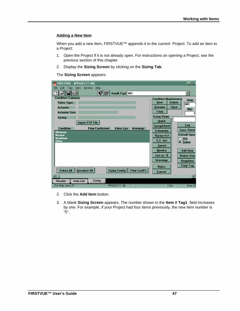
When you add a new item, FIRSTVUE™ appends it to the current Project. To add an item toa Project:
1. Open the Project if it is not already open. For instructions on opening a Project, see theprevious section of this chapter.
2. Display the Sizing Screen by clicking on the Sizing Tab.
The Sizing Screen appears:
2. Click the Add Item button.
3. A blank Sizing Screen appears. The number shown in the Item # Tag1 field increasesby one. For example, if your Project had four items previously, the new item number is“5”.
Chapter 4: Project Management Using FIRSTVUE™
48
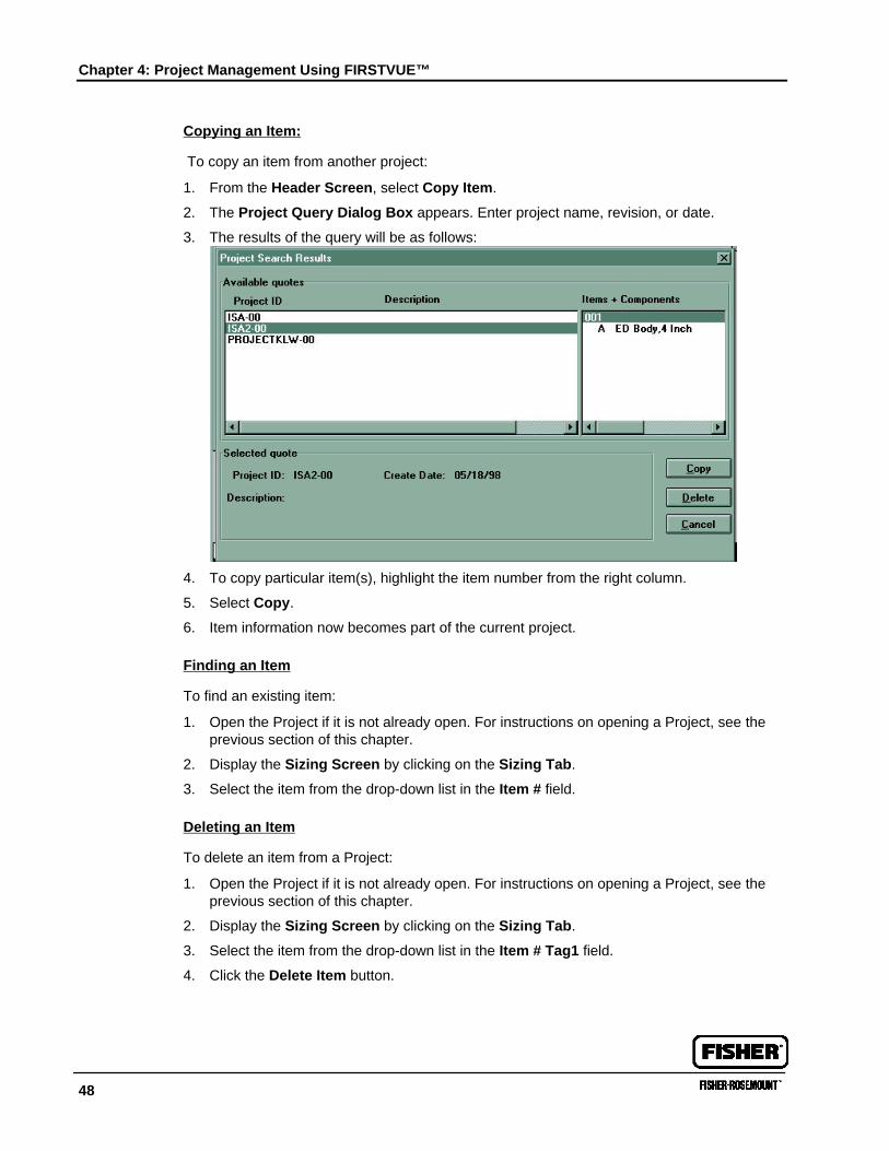
Copying an Item:
To copy an item from another project:
1. From the Header Screen, select Copy Item.
2. The Project Query Dialog Box appears. Enter project name, revision, or date.
3. The results of the query will be as follows:
4. To copy particular item(s), highlight the item number from the right column.
5. Select Copy.
6. Item information now becomes part of the current project.
Finding an Item
To find an existing item:
1. Open the Project if it is not already open. For instructions on opening a Project, see theprevious section of this chapter.
2. Display the Sizing Screen by clicking on the Sizing Tab.
3. Select the item from the drop-down list in the Item # field.
Deleting an Item
To delete an item from a Project:
1. Open the Project if it is not already open. For instructions on opening a Project, see theprevious section of this chapter.
2. Display the Sizing Screen by clicking on the Sizing Tab.
3. Select the item from the drop-down list in the Item # Tag1 field.
4. Click the Delete Item button.
Working with Items
FIRSTVUE™ User’s Guide 49
Adding, Changing, and Deleting Item Tags
FIRSTVUE™ lets you identify items with tags—names or numbers that you assign to the item.If your project contains more than one quantity of the same item, you can identify each itemwith its own tag. Your tags print on spec sheets and reports.
To add, change, or delete tags, you use the Item Tag Dialog Box. To display this screen:
1. Open the Project if it is not already open. For instructions on opening a Project, see theprevious section of this chapter.
2. Display the Sizing Screen by clicking on the Sizing Tab.
3. Select the item from the drop-down list in the Item # Tag1 field.
4. Click the Tag button.
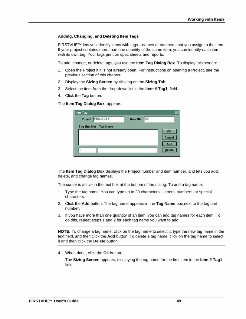
The Item Tag Dialog Box appears:
The Item Tag Dialog Box displays the Project number and item number, and lets you add,delete, and change tag names.
The cursor is active in the text box at the bottom of the dialog. To add a tag name:
1. Type the tag name. You can type up to 20 characters—letters, numbers, or specialcharacters.
2. Click the Add button. The tag name appears in the Tag Name box next to the tag unitnumber.
3. If you have more than one quantity of an item, you can add tag names for each item. Todo this, repeat steps 1 and 2 for each tag name you want to add.
NOTE: To change a tag name, click on the tag name to select it, type the new tag name in thetext field, and then click the Add button. To delete a tag name, click on the tag name to selectit and then click the Delete button.
4. When done, click the Ok button.
The Sizing Screen appears, displaying the tag name for the first item in the Item # Tag1field.
Chapter 4: Project Management Using FIRSTVUE™
50
Adding Project NotesProject notes let you add special shipping, packaging, and bar code requirements to yourproject. Unlike sizing notes, which allow only one note per item, a project can have unlimitednotes associated with it.
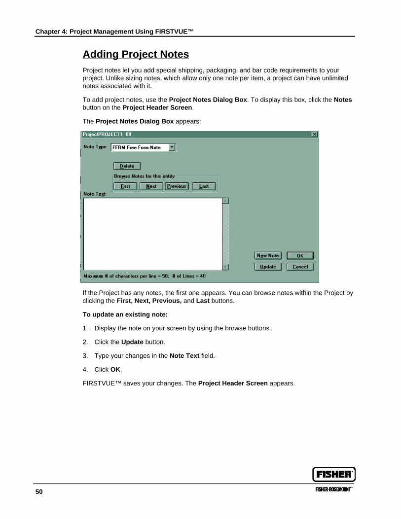
To add project notes, use the Project Notes Dialog Box. To display this box, click the Notesbutton on the Project Header Screen.
The Project Notes Dialog Box appears:
If the Project has any notes, the first one appears. You can browse notes within the Project byclicking the First, Next, Previous, and Last buttons.
To update an existing note:
1. Display the note on your screen by using the browse buttons.
2. Click the Update button.
3. Type your changes in the Note Text field.
4. Click OK.
FIRSTVUE™ saves your changes. The Project Header Screen appears.
Adding Project Notes
FIRSTVUE™ User’s Guide 51
To add a new note:
1. Select the type of note you want to add from the Note Type drop-down list. Fordescriptions of the note types, see the table at the end of this section.
2. Click the New Note button.
3. Type your note in the Note Text field.
4. Click OK.
FIRSTVUE™ saves your note. The Project Header Screen appears.
To delete a note:
1. Display the note on your screen by using the browse buttons.
1. Click the Delete button.
52
Chapter 5: Import/Export Capabilities ofFIRSTVUE™It is possible to import and export files from FIRSTVUE™ for use with different applicationsand software packages. Specifically, the following will be discussed:
• Using .MDB File Formats
• Importing and Exporting .FFV File Formats
• Importing and Exporting .BSV File Formats
• Importing and Exporting ISA File Formats
• Exporting Dimensional Data
Using .MDB File FormatsWhen you save projects using the Save command or pressing <Ctrl S>, FIRSTVUE™appends the data to the FIRSTVUE.MDB file in your FIRSTVUE™ directory. The .MDB fileformat is a Microsoft Access file format. If you are proficient in designing Access queries andreports, you can directly use the FIRSTVUE.MDB file for other uses. Since Access is aMicrosoft product, it can readily be transferred to and from Excel and Word.
Importing and Exporting .FFV File Formats.FFV file formats allow transferal of data from customer to representative and vice versa.The .FFV format, an acronym for FIRST FIRSTVUE, is recommended when working on largeprojects or when saving data to a network. .FFV file formats are also readily attached to e-mail for discussion with your local Fisher representative regarding sizing issues or formalrequest for quotation.
To save a project in .FFV format:
1. Select the File pull-down menu.
2. Select the Save to .FFV File option.
3. Follow the remaining instructions.
Importing and Exporting .BSV File FormatsBar separated value (.BSV) flat file formats are very similar to comma delimited file formats,except the character separating the fields is a vertical bar, “|”. In this file format, import andexport of FIRSTVUE™ data is possible to Intergraph’s Instrument Data Manager (IDMTM )software.
Importing and Exporting ISA File Formats
FIRSTVUE™ User’s Guide 53
The interface between IDM™ and FIRSTVUE™ begins in IDM™. The IDM™ user inputs tagnumbers and other pertinent valve information. Then, the export file is translated via someadditional software into .BSV file formats. This information is then imported by the followingsteps:
To import the “.BSV” file into FIRSTVUE:
1. Select Import ISA File from the FIRSTVUE file menu.
2. Select the file created in Step 5.
3. Click the Browse Map button
4. Select the “isa_all.csm” file.
5. Verify that the File Delimiter is set to “|”.
6. Click the Import button at the bottom of the window to start the import process.
7. As the import process runs, messages will appear in the Import Log. If any errormessages appear, click the Save Log button when the import process is finished. Enterthe name of a file to save the log to.
8. Click the Close button to close the window.
NOTE: FIRSTVUE imports items into the project you have open. If you get the error“Warning: No Active Document” it means that you don’t have a project open. Open a projectand try again.
The FIRSTVUETM import process is “add-only”. This means you cannot update existing itemsvia the import. Imported items are added to the end of the open project. For example, if youare working in a project that already has 3 items, the first item you import will be set to item 4.We recommend importing into a new project so that the first item you import will be item 1.
Data is imported into two places. Sizing fields are imported into sizing. Non-sizing fields areimported as ISA Spec Sheet User Overrides. Some fields are imported into both places.
Exporting is done in a similar manner. For more information, see the IDM/FIRSTVUEInterface User’s Manual.
Importing and Exporting ISA File FormatsFIRSTVUE can import and export ISA Sizing and Specification data to and from projects.When using this feature for a project, you should also use ISA Sizing and the ISA Spec Sheet.The data fields available for import/export include: all fields that appear on the current ISAS20.50 Control Valve Specification Sheet, fields required by ISA Sizing, and a few otherrelated fields. For a complete list of fields that can be imported/exported, check Appendix I atthe end of this manual. It is not necessary to import or export all of the available fields - youcan pick and choose just the fields you need.
Data is imported-from and exported-to a delimited text file. The first line of the file containsthe ordered field names of the data. The remaining file lines contain the actual data, witheach line representing one item of the project. Any printable character can be used as thefield delimiter.
The import will load the process conditions and sizing data into the appropriate fields withinFIRSTVUE. This data can then be used to generate a completed sizing for the item. Non-
Chapter 5: Import/Export Capabilities of FIRSTVUE™
54
sizing data will be imported as ISA spec sheet overrides where applicable, and can be viewedon the spec sheet dialog. The import process only adds items to a project - it does NOTupdate existing items.
Similarly, all the fields that can be imported into FIRSTVUE can be exported from FIRSTVUE.Before exporting, be sure to review the ISA spec sheet for each item being exported. Youcan export all or some of the items in a project.
Special features of the import/export are the ability to map user defined field names to thestandard FIRSTVUE ISA names and to import/export only the fields you need in any orderthat you want. These features are accomplished by building a comma separated “mapping”(.CSM) text file for each unique import/export format that you need. This mapping file alsoallows you to include “customer defined” fields which are imported and exported but neverused by FIRSTVUE (in effect they are place holders for fields not related to ISA data). Thefollowing sections detail how to Import an ISA file, Export an ISA file, and create a Mappingfile within FIRSTVUE.
Using FIRSTVUE’s ISA Import/Export functionality, Fisher has developed interfaces withIntergraph’s IDM and PID’s INtools instrumentation systems. These interfaces greatlyreduce the time required to exchange process and specification data with FIRSTVUE. Theyalso eliminate errors caused by the re-keying of data. To find out more about these interfacesand what you need to use them, contact your Fisher representative.
Importing an ISA Specification File:
1. You must have the project open that you want to import items into. The Importprocess will only create new items in your project, it will not update existing items.
2. Click on the ‘Import ISA File’ choice in the File Menu. This will bring up an Open FileDialog from which you can select the file you want to import. After selecting the file,the Import ISA File Dialog will appear with your file name displayed in the File Namefield. To change this file name click on the ‘Browse File’ button to select a differentimport file.
3. If a mapping file is needed in order to import this file, then select it by clicking on the‘Browse Map’ button or create a new one by clicking on the ‘Create/Edit Map’ button.After selecting/creating the mapping file, it’s name will appear in the Map File To Usefield.
4. Select the File Delimiter for the file you are importing. You can select a character fromthe dropdown list, or key-in any printable character.
5. Click on the ‘Import’ button to begin the import process. The Import Log list box willshow the status of your import as well as any errors that might occur. The log can besaved to a file if needed by clicking the ‘Save Log’ button. If errors occurred the importfile can be corrected by manually editing it with most text editors or if the lines are toolong, with a spreadsheet program such as Microsoft Excel. Errors in field names willcause an item to NOT be created. Errors in field data will cause that field to not beimported and left blank, but the item will still be created. Errors in unit of measure for afield will also cause an item to NOT be created.
6. Click on the ‘Close’ button to exit the Import ISA File Dialog.
Importing and Exporting ISA File Formats
FIRSTVUE™ User’s Guide 55
Exporting an ISA Specification File:
1. You must have the project open that you want to export items from.
2. Click on the ‘Export ISA File’ choice in the File Menu. This will bring up the Export ISAFile Dialog.
3. Click on the ‘Browse File’ button to select the file name you want to export to. Afterselecting the file, it’s name will appear in the File Name field.
4. If the export file only needs certain fields, or needs a unique order, or needs unique fieldnames then you need to select or create (see Creating or Editing an ISA Mapping File) amapping file by clicking on the ‘Browse Map’ or ‘Create/Edit Map’ button. Afterselecting/creating the mapping file, it’s name will appear in the Map File To Use field. Ifno map file is specified, the export will contain ALL fields in the default order with standardnames.
5. Two other radio button selections come into play if you are using a mapping file to export.If you want to use a mapping file, but want to export the standard field names; then clickthe Standard ISA Names button. If you want to ignore the mapping file; then click the AllFields button. Generally you will accept the settings defaulted to, but these options allowfor complete flexibility.
6. Select the File Delimiter that you want to use for the file you are exporting. You canselect a character from the dropdown list, or key-in any printable character. This is thecharacter that will be used to separate fields values within the export file.
7. A list of all items on the project appears in the Select Items to Export listbox. You canselect which items you want to export here by clicking on them individually, or click theSelect All Items check box if you want to export all the items on this project.
8. Click on the ‘Export’ button to begin the export process. This will bring up an Open FileDialog from which you can select the path and file name of the export file you want tocreate. After selecting the file name, a status box will appear telling you the item which iscurrently being exported and at the end telling you the results of your export. The exportfile can be viewed with most text editors or if the lines are too long, with a spreadsheetprogram such as Microsoft Excel.
9. Click on the ‘Close’ button to exit the Export ISA File Dialog.
Creating or Editing an ISA Mapping File:
1. Click on the ‘Edit ISA Map File’ choice in the File Menu or click the ‘Create/Edit Map’button from the Import or Export Dialogs. This will bring up the Map File Edit Dialog.
5. To open an existing map file click on the ‘Open Map File’ button to select the file. Afterselecting the file, it’s name will appear in the Map File Name field and the fieldsassociated with that file will appear in the Fields Selected/Custom Name spreadsheet onthe right side of the screen. If you are creating a new map file, the FieldsSelected/Custom Name spreadsheet will be empty initially.
6. The Fields Available list on the left side of the screen lists all the non-selected fieldsavailable with the Fisher standard field name. The order of these fields is roughly top tobottom on a Standard ISA printed spec sheet. To Add a field or fields to a map file, selectthe Add/Delete button in the Select Mode box, click the fields desired to highlight them inthe Fields Available list, then click on the ‘Select >‘ button to move them over to the FieldsSelected List. All the fields can be selected with the ‘Select All >>‘ button. Deselecting
Chapter 5: Import/Export Capabilities of FIRSTVUE™
56
works the same way, but in the opposite direction using the ‘< Deselect ‘ and ‘<< DeselectAll’ buttons. A special “CUSTOMER-DEFINED” field is listed first in the list. This fieldallows for Non-ISA fields to be allowed for in an import or export file. This field can beselected as many times as needed and renamed (see 5 below) to a custom name just likethe rest of the fields.
7. To change the field order of your map file, highlight the field in the Fields Selected/CustomName spreadsheet and click the ‘Move UP’ or ‘Move DOWN’ buttons to move that field upor down in the order. Multiple fields can be moved at once by highlighting a group offields.
8. To define a custom field name for a field simply type the name in the Custom Namecolumn of the spreadsheet next to the standard name you want it to stand for. To resetALL custom names to the default standard name click the ‘Reset Custom Names’ button.
9. If you have a copy of the customer import file you can import it to make the building of themap easier by entering the Delimiter of the file and clicking the Import Custom File button.This will load the custom names in row one of the file into the Custom Name column ofthe Fields Selected/Custom Name spreadsheet while leaving the Fields Selected columnblank. The Overlay button will be selected in the Select Mode box and you can nowhighlight fields in the Fields Available list and Select them to “overlay” the blank fields inthe spreadsheet. Deselecting while in Overlay mode will blank out the highlighted field(s).
10. Click the ‘Save’ button to save to the file listed in the Map File Name field. Click the‘Save As’ button to save to a new or different map file name.
11. Click on the ‘Close’ button to exit the Map File Edit Dialog. **Important: Closing thedialog does NOT automatically save your map file. You must click the ‘Save’ or ‘Save As’buttons to save your file.
Exporting Dimensional DataAfter valve selections have been made in FIRSTVUETM and Autodraw has assembled Type Idrawings by tag number, it is possible to export a table to dimensions into Excel by tagnumber. It can also provide a by tag basis for each dimension which can be imported intoCAD systems that can accept Excel spreadsheets.
57
Chapter 6: Creating Specification Sheets andReportsFIRSTVUE™ lets you create three types of reports: Summary Reports, Sizing CalculationReports, and Specification (Spec) Sheets.
A Summary Report lists selected items in a Project and includes a brief description of eachitem. A Sizing Calculation Report shows criteria you entered for a selected process conditionand the calculated results.
This chapter contains instructions for creating and printing reports and includes an example ofeach type of report. It contains the following sections:
• Creating a Spec Sheet
• Printing Spec Sheets and Reports
• FIRSTVUE™ Reports Examples
Summary Report
Sizing Calculations Reports
Fisher Spec Sheet
ISA Spec Sheet
Diffuser Spec Sheet
Creating a Spec SheetWhen you create a specification sheet, you first use the Spec Sheet Data Dialog Box toselect data and then use the Reports Dialog Box to select the specification sheet types andother options for printing.
To display the Spec Sheet Data Dialog Box:
1. Open the appropriate Project. For instructions on opening a Project, see Chapter 4:Creating and Opening Projects and Items.
2. Display the Sizing Screen by clicking on the Sizing Tab.
3. Click the Spec Sheet button.
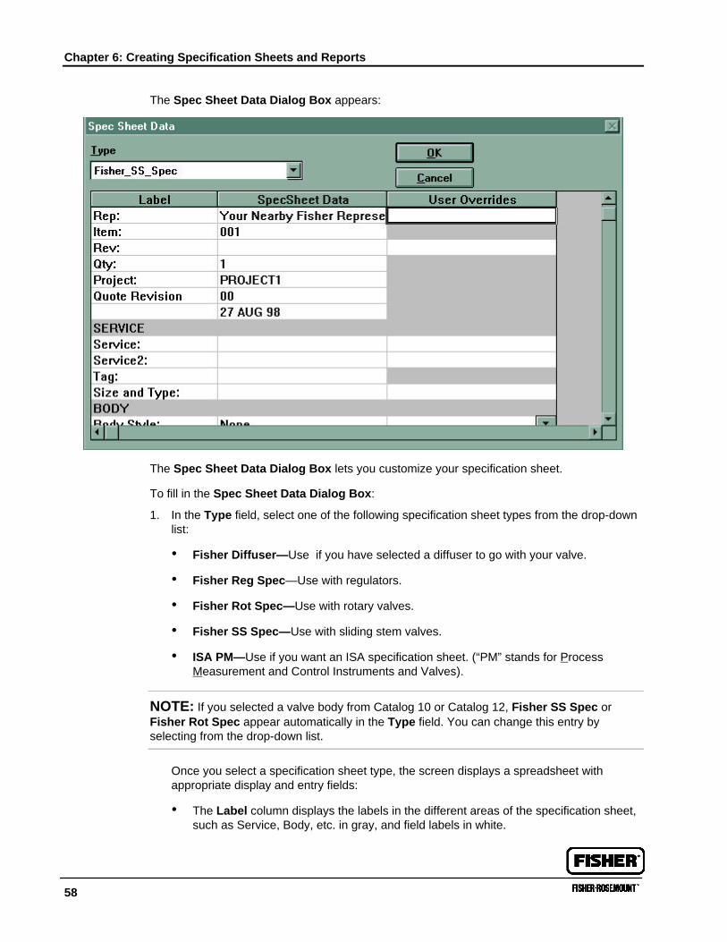
Chapter 6: Creating Specification Sheets and Reports
58
The Spec Sheet Data Dialog Box appears:
The Spec Sheet Data Dialog Box lets you customize your specification sheet.
To fill in the Spec Sheet Data Dialog Box:
1. In the Type field, select one of the following specification sheet types from the drop-downlist:
• Fisher Diffuser—Use if you have selected a diffuser to go with your valve.
• Fisher Reg Spec—Use with regulators.
• Fisher Rot Spec—Use with rotary valves.
• Fisher SS Spec—Use with sliding stem valves.
• ISA PM—Use if you want an ISA specification sheet. (“PM” stands for ProcessMeasurement and Control Instruments and Valves).
NOTE: If you selected a valve body from Catalog 10 or Catalog 12, Fisher SS Spec orFisher Rot Spec appear automatically in the Type field. You can change this entry byselecting from the drop-down list.
Once you select a specification sheet type, the screen displays a spreadsheet withappropriate display and entry fields:
• The Label column displays the labels in the different areas of the specification sheet,such as Service, Body, etc. in gray, and field labels in white.
Printing Spec Sheets and Reports
FIRSTVUE™ User’s Guide 59
• The SpecSheet Data column displays the data provided by the program.
2. Make any changes you like by selecting or typing in the User Overrides column.
3. Note any additional components or accessories on your specification sheet by enteringinformation and selecting from drop-down lists the Positioner, Controller, Transducer,and Other sections.
4. When done making changes, click OK to save your entries. The Sizing Screen appears.
Printing Spec Sheets and ReportsTo print specification sheets and Summary Reports, you use the Reports Dialog Box. Todisplay this dialog:
1. Open the appropriate Project. For instructions on opening a Project, see Chapter 4:Creating and Opening Projects and Items.
2. From the File Menu, select Reports.
OR
Click the Printer icon located on the Toolbar.
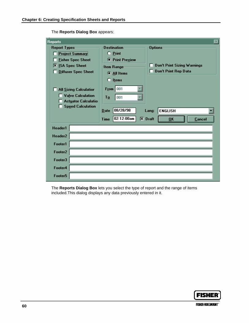
Chapter 6: Creating Specification Sheets and Reports
60
The Reports Dialog Box appears:
The Reports Dialog Box lets you select the type of report and the range of itemsincluded.This dialog displays any data previously entered in it.
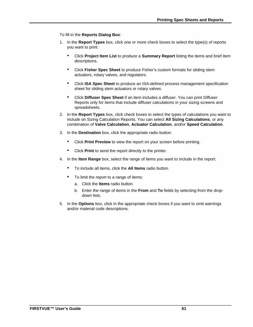
Printing Spec Sheets and Reports
FIRSTVUE™ User’s Guide 61
To fill in the Reports Dialog Box:
1. In the Report Types box, click one or more check boxes to select the type(s) of reportsyou want to print:
• Click Project Item List to produce a Summary Report listing the items and brief itemdescriptions.
• Click Fisher Spec Sheet to produce Fisher’s custom formats for sliding stemactuators, rotary valves, and regulators.
• Click ISA Spec Sheet to produce an ISA-defined process management specificationsheet for sliding stem actuators or rotary valves.
• Click Diffuser Spec Sheet if an item includes a diffuser. You can print DiffuserReports only for items that include diffuser calculations in your sizing screens andspreadsheets.
2. In the Report Types box, click check boxes to select the types of calculations you want toinclude on Sizing Calculation Reports. You can select All Sizing Calculations, or anycombination of Valve Calculation, Actuator Calculation, and/or Speed Calculation.
3. In the Destination box, click the appropriate radio button:
• Click Print Preview to view the report on your screen before printing.
• Click Print to send the report directly to the printer.
4. In the Item Range box, select the range of items you want to include in the report:
• To include all items, click the All Items radio button.
• To limit the report to a range of items:
a. Click the Items radio button.
b. Enter the range of items in the From and To fields by selecting from the drop-down lists.
5. In the Options box, click in the appropriate check boxes if you want to omit warningsand/or material code descriptions.
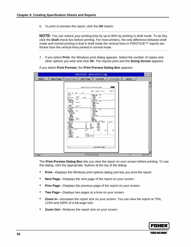
Chapter 6: Creating Specification Sheets and Reports
62
6. To print or preview the report, click the OK button.
NOTE: You can reduce your printing time by up to 80% by printing in draft mode. To do this,click the Draft check box before printing. For most printers, the only difference between draftmode and normal printing is that in draft mode the vertical lines in FIRSTVUE™ reports arethicker than the vertical lines printed in normal mode.
7. If you select Print, the Windows print dialog appears. Select the number of copies andother options you wish and click Ok. The reports print and the Sizing Screen appears.
If you select Print Preview, the Print Preview Dialog Box appears:
The Print Preview Dialog Box lets you view the report on your screen before printing. To usethis dialog, click the appropriate buttons at the top of the dialog:
• Print—Displays the Windows print options dialog and lets you print the report.
• Next Page—Displays the next page of the report on your screen.
• Prev Page—Displays the previous page of the report on your screen.
• Two Page—Displays two pages at a time on your screen.
• Zoom In—Increases the report size on your screen. You can view the report at 75%,110% and 200% of a full page size.
• Zoom Out—Reduces the report size on your screen.
FIRSTVUE™ Reports Examples
FIRSTVUE™ User’s Guide 63
NOTE: You can use the vertical scroll bar on the right of the screen to move within a pageand from page to page. When the screen displays a full page, scrolling takes you to the nextor previous pages. When the screen displays part of a page in expanded views, scrollingmoves you within the page.
FIRSTVUE™ Reports ExamplesFIRSTVUE™ lets you create the following types of reports:
• Summary Report—Lists each item in a Project and a brief description of each item.
• Sizing Calculation Report—Contains the sizing data you entered and calculated resultsfor a selected condition.
• Fisher Spec Sheet—Uses Fisher’s custom formats to display sliding stem actuator,rotary valve, and regulator specifications.
• ISA Spec Sheet—Uses ISA-defined process management format to display sliding stemactuator or rotary valve specifications.
• Diffuser Spec Sheet—Displays diffuser data.
The following pages contain examples of each type of report.
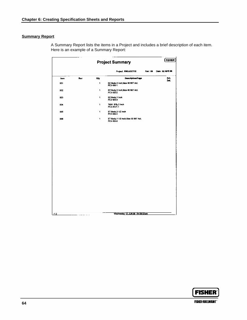
Chapter 6: Creating Specification Sheets and Reports
64
Summary Report
A Summary Report lists the items in a Project and includes a brief description of each item.Here is an example of a Summary Report:
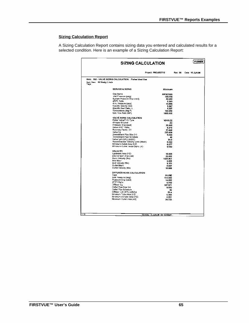
FIRSTVUE™ Reports Examples
FIRSTVUE™ User’s Guide 65
Sizing Calculation Report
A Sizing Calculation Report contains sizing data you entered and calculated results for aselected condition. Here is an example of a Sizing Calculation Report:
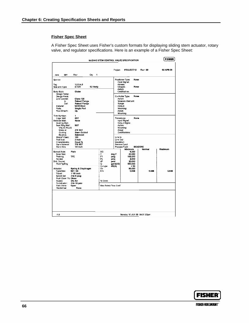
Chapter 6: Creating Specification Sheets and Reports
66
Fisher Spec Sheet
A Fisher Spec Sheet uses Fisher’s custom formats for displaying sliding stem actuator, rotaryvalve, and regulator specifications. Here is an example of a Fisher Spec Sheet:
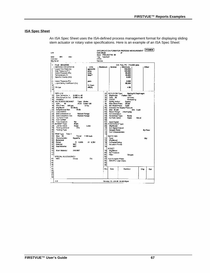
FIRSTVUE™ Reports Examples
FIRSTVUE™ User’s Guide 67
ISA Spec Sheet
An ISA Spec Sheet uses the ISA-defined process management format for displaying slidingstem actuator or rotary valve specifications. Here is an example of an ISA Spec Sheet:
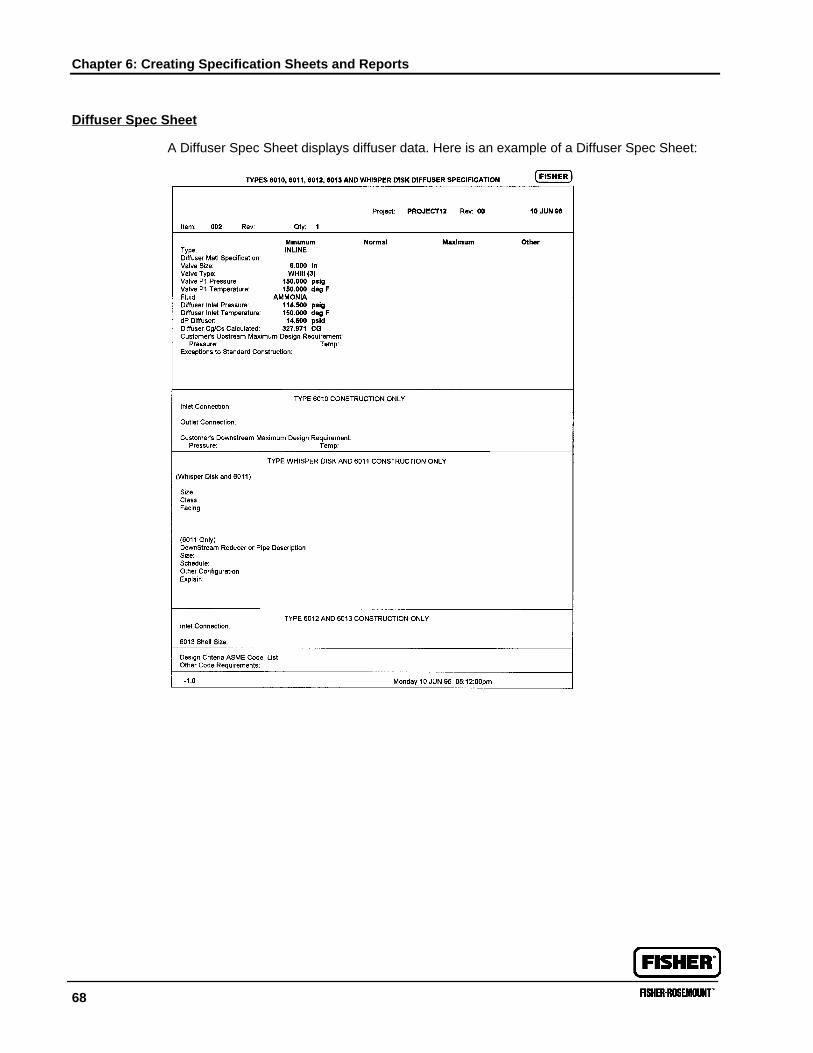
Chapter 6: Creating Specification Sheets and Reports
68
Diffuser Spec Sheet
A Diffuser Spec Sheet displays diffuser data. Here is an example of a Diffuser Spec Sheet:
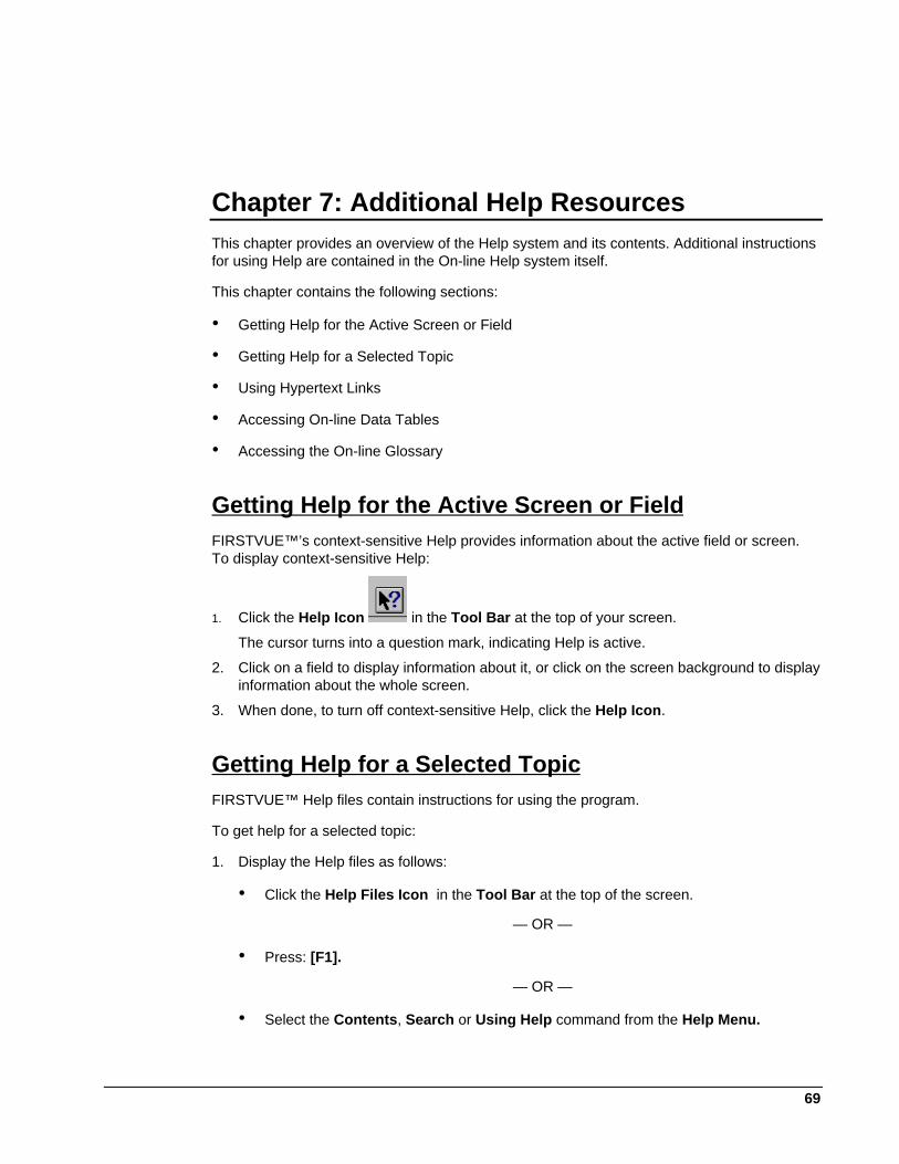
69
Chapter 7: Additional Help ResourcesThis chapter provides an overview of the Help system and its contents. Additional instructionsfor using Help are contained in the On-line Help system itself.
This chapter contains the following sections:
• Getting Help for the Active Screen or Field
• Getting Help for a Selected Topic
• Using Hypertext Links
• Accessing On-line Data Tables
• Accessing the On-line Glossary
Getting Help for the Active Screen or FieldFIRSTVUE™’s context-sensitive Help provides information about the active field or screen.To display context-sensitive Help:
1. Click the Help Icon in the Tool Bar at the top of your screen.
The cursor turns into a question mark, indicating Help is active.
2. Click on a field to display information about it, or click on the screen background to displayinformation about the whole screen.
3. When done, to turn off context-sensitive Help, click the Help Icon.
Getting Help for a Selected TopicFIRSTVUE™ Help files contain instructions for using the program.
To get help for a selected topic:
1. Display the Help files as follows:
• Click the Help Files Icon in the Tool Bar at the top of the screen.
— OR —
• Press: [F1].
— OR —
• Select the Contents, Search or Using Help command from the Help Menu.
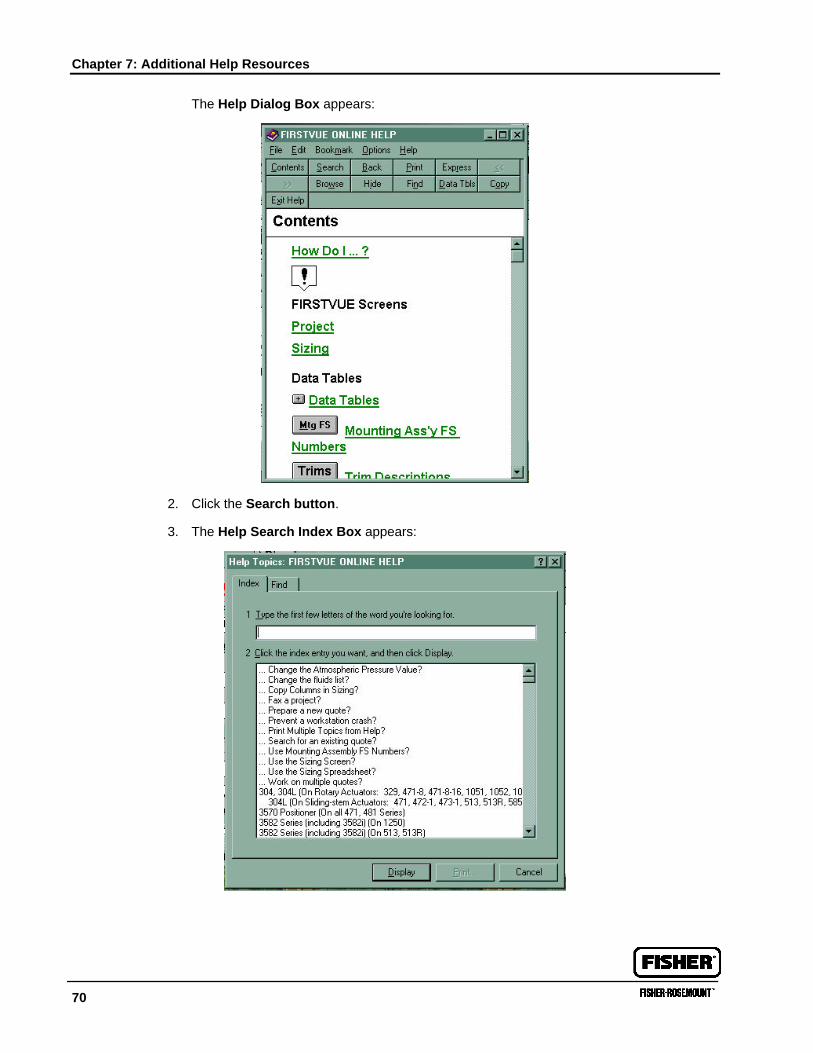
Chapter 7: Additional Help Resources
70
The Help Dialog Box appears:
2. Click the Search button.
3. The Help Search Index Box appears:
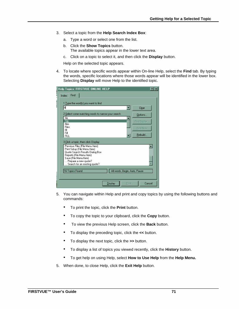
Getting Help for a Selected Topic
FIRSTVUE™ User’s Guide 71
3. Select a topic from the Help Search Index Box:
a. Type a word or select one from the list.
b. Click the Show Topics button.The available topics appear in the lower text area.
c. Click on a topic to select it, and then click the Display button.
Help on the selected topic appears.
4. To locate where specific words appear within On-line Help, select the Find tab. By typingthe words, specific locations where those words appear will be identified in the lower box.Selecting Display will move Help to the identified topic.
5. You can navigate within Help and print and copy topics by using the following buttons andcommands:
• To print the topic, click the Print button.
• To copy the topic to your clipboard, click the Copy button.
• To view the previous Help screen, click the Back button.
• To display the preceding topic, click the << button.
• To display the next topic, click the >> button.
• To display a list of topics you viewed recently, click the History button.
• To get help on using Help, select How to Use Help from the Help Menu.
5. When done, to close Help, click the Exit Help button.
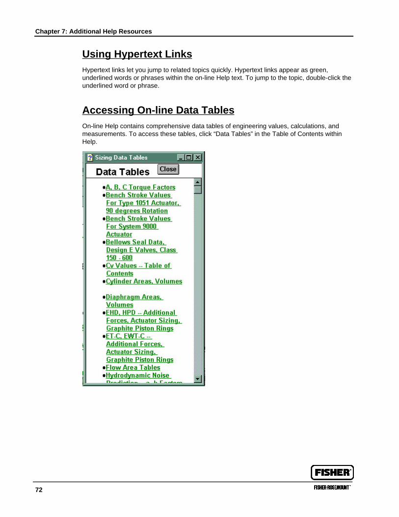
Chapter 7: Additional Help Resources
72
Using Hypertext LinksHypertext links let you jump to related topics quickly. Hypertext links appear as green,underlined words or phrases within the on-line Help text. To jump to the topic, double-click theunderlined word or phrase.
Accessing On-line Data TablesOn-line Help contains comprehensive data tables of engineering values, calculations, andmeasurements. To access these tables, click “Data Tables” in the Table of Contents withinHelp.
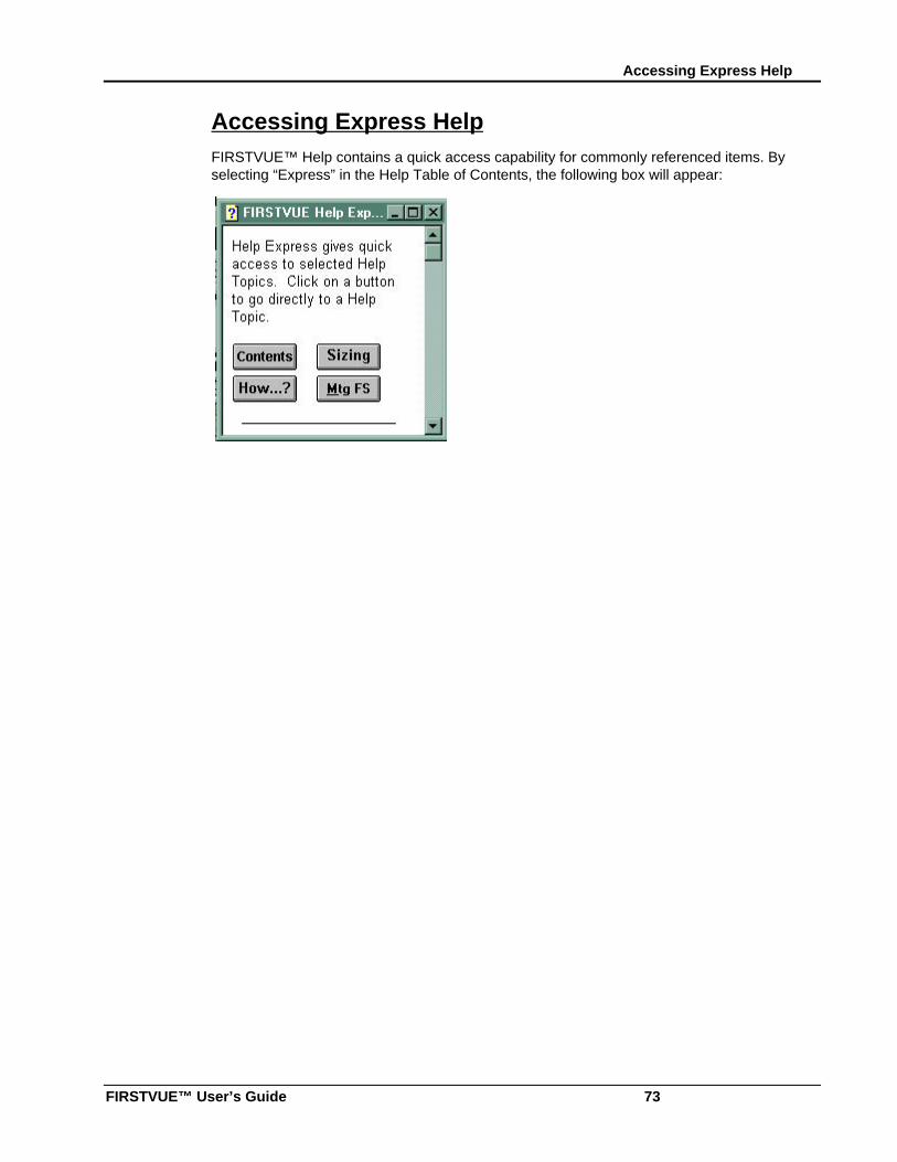
Accessing Express Help
FIRSTVUE™ User’s Guide 73
Accessing Express HelpFIRSTVUE™ Help contains a quick access capability for commonly referenced items. Byselecting “Express” in the Help Table of Contents, the following box will appear:
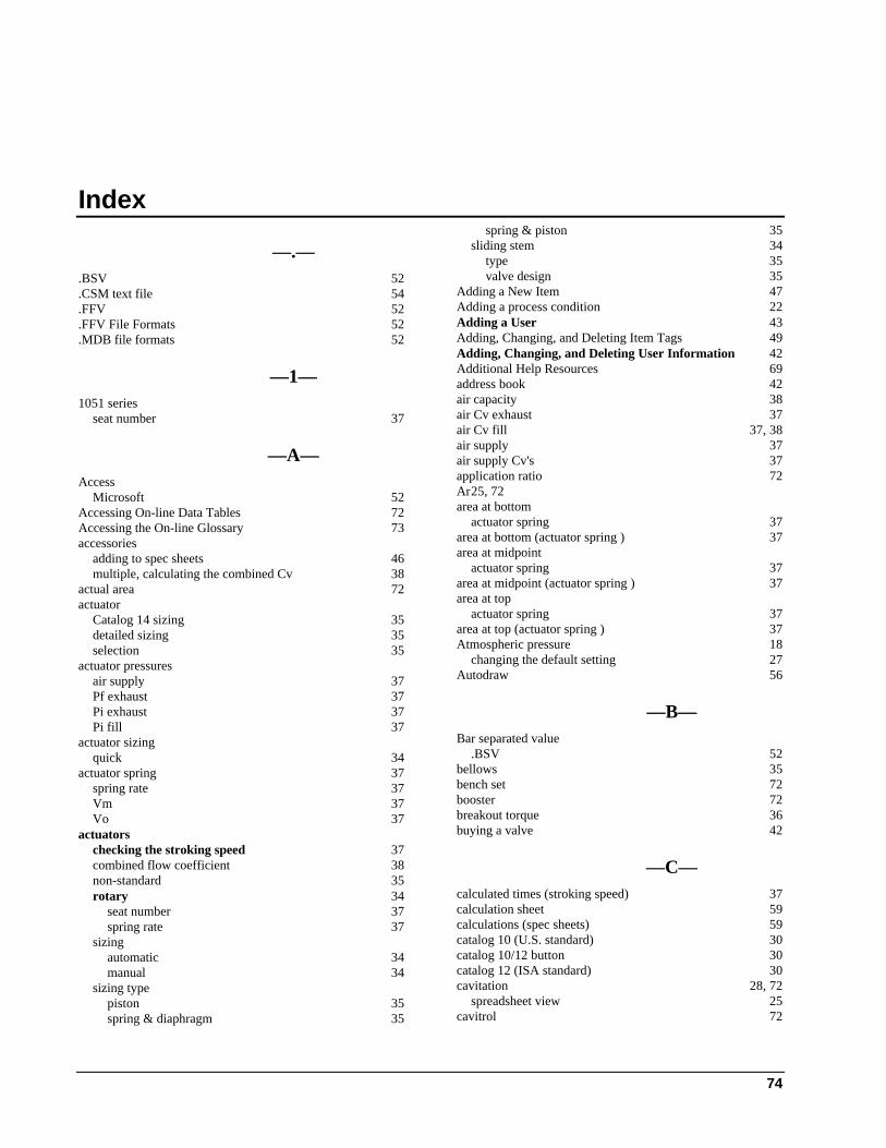
74
Index
—.—.BSV 52.CSM text file 54.FFV 52.FFV File Formats 52.MDB file formats 52
—1—1051 series
seat number 37
—A—Access
Microsoft 52Accessing On-line Data Tables 72Accessing the On-line Glossary 73accessories
adding to spec sheets 46multiple, calculating the combined Cv 38
actual area 72actuator
Catalog 14 sizing 35detailed sizing 35selection 35
actuator pressuresair supply 37Pf exhaust 37Pi exhaust 37Pi fill 37
actuator sizingquick 34
actuator spring 37spring rate 37Vm 37Vo 37
actuatorschecking the stroking speed 37combined flow coefficient 38non-standard 35rotary 34
seat number 37spring rate 37
sizingautomatic 34manual 34
sizing typepiston 35spring & diaphragm 35
spring & piston 35sliding stem 34
type 35valve design 35
Adding a New Item 47Adding a process condition 22Adding a User 43Adding, Changing, and Deleting Item Tags 49Adding, Changing, and Deleting User Information 42Additional Help Resources 69address book 42air capacity 38air Cv exhaust 37air Cv fill 37, 38air supply 37air supply Cv's 37application ratio 72Ar25, 72area at bottom
actuator spring 37area at bottom (actuator spring ) 37area at midpoint
actuator spring 37area at midpoint (actuator spring ) 37area at top
actuator spring 37area at top (actuator spring ) 37Atmospheric pressure 18
changing the default setting 27Autodraw 56
—B—Bar separated value
.BSV 52bellows 35bench set 72booster 72breakout torque 36buying a valve 42
—C—calculated times (stroking speed) 37calculation sheet 59calculations (spec sheets) 59catalog 10 (U.S. standard) 30catalog 10/12 button 30catalog 12 (ISA standard) 30cavitation 28, 72
spreadsheet view 25cavitrol 72
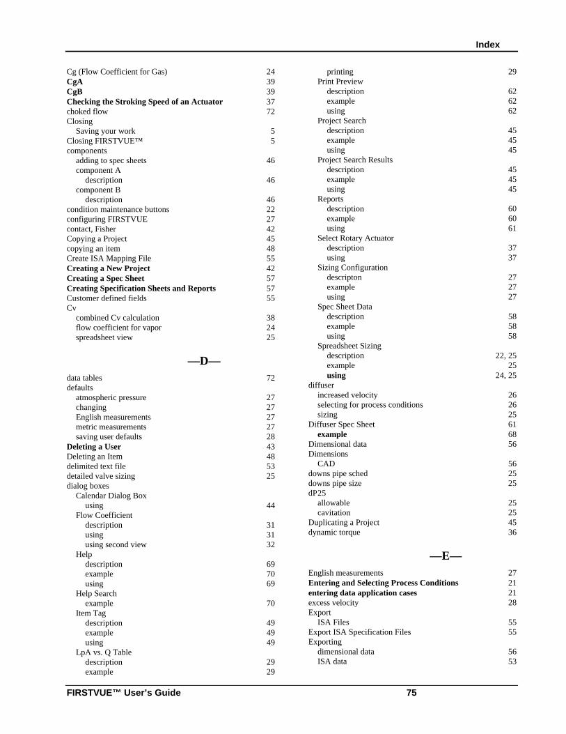
Index
FIRSTVUE™ User’s Guide 75
Cg (Flow Coefficient for Gas) 24CgA 39CgB 39Checking the Stroking Speed of an Actuator 37choked flow 72Closing
Saving your work 5Closing FIRSTVUE™ 5components
adding to spec sheets 46component A
description 46component B
description 46condition maintenance buttons 22configuring FIRSTVUE 27contact, Fisher 42Copying a Project 45copying an item 48Create ISA Mapping File 55Creating a New Project 42Creating a Spec Sheet 57Creating Specification Sheets and Reports 57Customer defined fields 55Cv
combined Cv calculation 38flow coefficient for vapor 24spreadsheet view 25
—D—data tables 72defaults
atmospheric pressure 27changing 27English measurements 27metric measurements 27saving user defaults 28
Deleting a User 43Deleting an Item 48delimited text file 53detailed valve sizing 25dialog boxes
Calendar Dialog Boxusing 44
Flow Coefficientdescription 31using 31using second view 32
Helpdescription 69example 70using 69
Help Searchexample 70
Item Tagdescription 49example 49using 49
LpA vs. Q Tabledescription 29example 29
printing 29Print Preview
description 62example 62using 62
Project Searchdescription 45example 45using 45
Project Search Resultsdescription 45example 45using 45
Reportsdescription 60example 60using 61
Select Rotary Actuatordescription 37using 37
Sizing Configurationdescripton 27example 27using 27
Spec Sheet Datadescription 58example 58using 58
Spreadsheet Sizingdescription 22, 25example 25using 24, 25
diffuserincreased velocity 26selecting for process conditions 26sizing 25
Diffuser Spec Sheet 61example 68
Dimensional data 56Dimensions
CAD 56downs pipe sched 25downs pipe size 25dP25
allowable 25cavitation 25
Duplicating a Project 45dynamic torque 36
—E—English measurements 27Entering and Selecting Process Conditions 21entering data application cases 21excess velocity 28Export
ISA Files 55Export ISA Specification Files 55Exporting
dimensional data 56ISA data 53
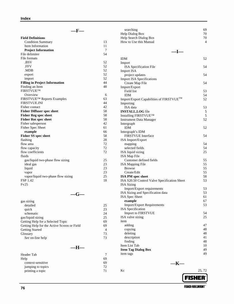
Index
76
—F—Field Definitions
Condition Summary 13Item Information 11Project Information 7
File delimiter 54File formats
.BSV 52
.FFV 52
.MDB 52export 52import 52
Filling in Project Information 44Finding an Item 48FIRSTVUE™
Overview 6FIRSTVUE™ Reports Examples 63FIRSTVUE.INI 44Fisher contact 42Fisher Diffuser spec sheet 58Fisher Reg spec sheet 58Fisher Rot spec sheet 58Fisher salesperson 42Fisher Spec Sheet 61
example 66Fisher SS spec sheet 58flashing 28flow area 72flow capacity 72flow coefficients 72fluids
gas/liquid two-phase flow sizing 25ideal gas 23liquid 23vapor 23vapor/liquid two-phase flow sizing 25
FSP 1.42 18Fv25
—G—gas sizing
detailed 25quick 23schematic 24
gas/liquid sizing 25Getting Help for a Selected Topic 69Getting Help for the Active Screen or Field 69Getting Started 4Glossary 73
See on-line help 73
—H—Header Tab 7Help 69
context-sensitive 69jumping to topics 72printing a topic 71
searching 69Help Dialog Box 70Help Search Dialog Box 70How to Use this Manual 4
—I—IDM 52Import
ISA Specification File 54Import ISA
project updates 54Import ISA Specifications
Create Map File 54Import/Export
Field list 53IDM 54
Import/Export Capabilities of FIRSTVUETM 52Importing
ISA data 53INSTALL.LOG file 5Installing FIRSTVUE™ 5Instrument Data Manager 52Intergraph
IDM 52Intergraph’s IDM
FIRSTVUE Interface 54ISA Import/Export
mapping 54selected fields 54
ISA liquid sizing 25ISA Map File
Customer defined fields 55ISA Mapping File 55
Browse 55Create/Edit 55
ISA PM spec sheet 58ISA S20.50 Control Valve Specification Sheet 53ISA Sizing
Import/Export requirements 53ISA Sizing and Specification data 53ISA Spec Sheet 61
example 67Import/Export Requirements 53
ISA SpecificationImport to FIRSTVUE 54
ISA valve sizing 25item
adding 47copying 48deleting 48description 41finding 48
Item List Tab 10Item Tag Dialog Box 49item tags 49
—K—Kc 25, 72
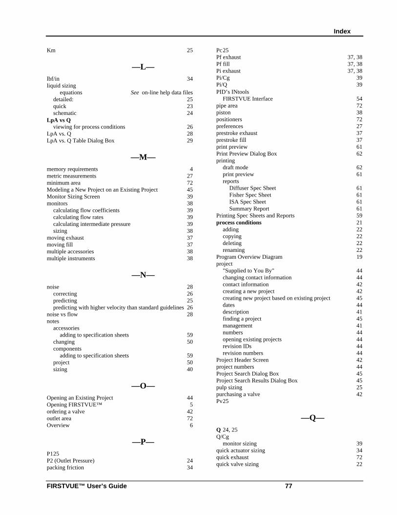
Index
FIRSTVUE™ User’s Guide 77
Km 25
—L—lbf/in 34liquid sizing
equations See on-line help data filesdetailed: 25quick 23schematic 24
LpA vs Qviewing for process conditions 26
LpA vs. Q 28LpA vs. Q Table Dialog Box 29
—M—memory requirements 4metric measurements 27minimum area 72Modeling a New Project on an Existing Project 45Monitor Sizing Screen 39monitors 38
calculating flow coefficients 39calculating flow rates 39calculating intermediate pressure 39sizing 38
moving exhaust 37moving fill 37multiple accessories 38multiple instruments 38
—N—noise 28
correcting 26predicting 25predicting with higher velocity than standard guidelines 26
noise vs flow 28notes
accessoriesadding to specification sheets 59
changing 50components
adding to specification sheets 59project 50sizing 40
—O—Opening an Existing Project 44Opening FIRSTVUE™ 5ordering a valve 42outlet area 72Overview 6
—P—P125P2 (Outlet Pressure) 24packing friction 34
Pc25Pf exhaust 37, 38Pf fill 37, 38Pi exhaust 37, 38Pi/Cg 39Pi/Q 39PID’s INtools
FIRSTVUE Interface 54pipe area 72piston 38positioners 72preferences 27prestroke exhaust 37prestroke fill 37print preview 61Print Preview Dialog Box 62printing
draft mode 62print preview 61reports
Diffuser Spec Sheet 61Fisher Spec Sheet 61ISA Spec Sheet 61Summary Report 61
Printing Spec Sheets and Reports 59process conditions 21
adding 22copying 22deleting 22renaming 22
Program Overview Diagram 19project
"Supplied to You By" 44changing contact information 44contact information 42creating a new project 42creating new project based on existing project 45dates 44description 41finding a project 45management 41numbers 44opening existing projects 44revision IDs 44revision numbers 44
Project Header Screen 42project numbers 44Project Search Dialog Box 45Project Search Results Dialog Box 45pulp sizing 25purchasing a valve 42Pv25
—Q—Q 24, 25Q/Cg
monitor sizing 39quick actuator sizing 34quick exhaust 72quick valve sizing 22
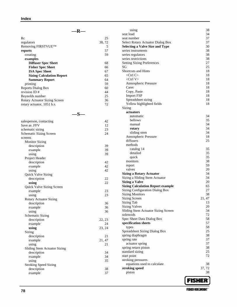
Index
78
—R—Rc 25regulators 38, 72Removing FIRSTVUE™ 5reports 57
creating 59examples
Diffuser Spec Sheet 68Fisher Spec Sheet 66ISA Spec Sheet 67Sizing Calculation Report 65Summary Report 64
printing 59Reports Dialog Box 60revision ID # 44Reynolds number 25Rotary Actuator Sizing Screen 36rotary actuator, 1051 b.s. 72
—S—salesperson, contacting 42Save as .FFV 12schematic sizing 23Schematic Sizing Screen 24screens
Monitor Sizingdescription 39example 39using 39
Project Headerdescription 42example 42using 42
Quick Valve Sizingdescription 22using 22
Quick Valve Sizing Screenexample 23using 23
Rotary Actuator Sizingdescription 36example 36using 36
Schematic Sizingdescription 22, 23example 24using 23, 24
Sizingdescription 21example 21, 47using 21
Sliding Stem Actuator Sizingdescription 34example 34using 35
Stroking Speed Sizingdescription 38example 37
using 38seat load 34seat number 37Select Rotary Actuator Dialog Box 37Selecting a Valve Size and Type 30series instruments 38series regulators 38series restrictions 38Setting Sizing Preferences 27SG 25Shortcuts and Hints 18
<Ctrl C> 18<Ctrl V> 18Atmospheric Pressure 18Caret 18Copy, Paste 18Import FSP 18Spreadsheet sizing 18Yellow highlighted fields 18
Sizingactuators
automatic 34bellows 35manual 34rotary 34sliding stem 34
Atmospheric Pressure 18diffusers 25methods
catalog 14 35detailed 35quick 35
monitors 38report 59valves 20
Sizing a Rotary Actuator 34Sizing a Sliding Stem Actuator 34Sizing a Valve 20Sizing Calculation Report example 65Sizing Configuration Dialog Box 27Sizing Monitors 38Sizing Screen 21, 47Sizing Tab 13Sizing Valves 20Sliding Stem Actuator Sizing Screen 34solenoids 72Spec Sheet Data Dialog Box 58specification sheets 57
types 58Spreadsheet Sizing Dialog Box 25spring diaphragm 38spring rate 37
actuator spring 37spring return piston 38standard sizing 25start point 72stroking pressures
equations used to calculate 38stroking speed 37, 72
piston 38
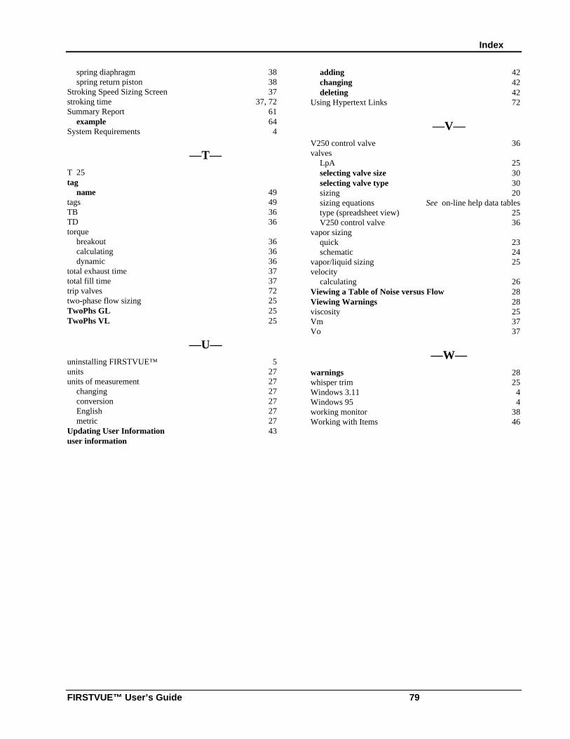
Index
FIRSTVUE™ User’s Guide 79
spring diaphragm 38spring return piston 38
Stroking Speed Sizing Screen 37stroking time 37, 72Summary Report 61
example 64System Requirements 4
—T—T 25tag
name 49tags 49TB 36TD 36torque
breakout 36calculating 36dynamic 36
total exhaust time 37total fill time 37trip valves 72two-phase flow sizing 25TwoPhs GL 25TwoPhs VL 25
—U—uninstalling FIRSTVUE™ 5units 27units of measurement 27
changing 27conversion 27English 27metric 27
Updating User Information 43user information
adding 42changing 42deleting 42
Using Hypertext Links 72
—V—V250 control valve 36valves
LpA 25selecting valve size 30selecting valve type 30sizing 20sizing equations See on-line help data tablestype (spreadsheet view) 25V250 control valve 36
vapor sizingquick 23schematic 24
vapor/liquid sizing 25velocity
calculating 26Viewing a Table of Noise versus Flow 28Viewing Warnings 28viscosity 25Vm 37Vo 37
—W—warnings 28whisper trim 25Windows 3.11 4Windows 95 4working monitor 38Working with Items 46
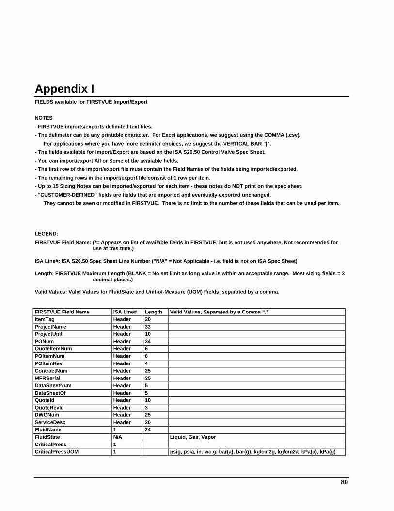
80
Appendix IFIELDS available for FIRSTVUE Import/Export
NOTES
- FIRSTVUE imports/exports delimited text files.
- The delimeter can be any printable character. For Excel applications, we suggest using the COMMA (.csv).
For applications where you have more delimiter choices, we suggest the VERTICAL BAR "|".
- The fields available for Import/Export are based on the ISA S20.50 Control Valve Spec Sheet.
- You can import/export All or Some of the available fields.
- The first row of the import/export file must contain the Field Names of the fields being imported/exported.
- The remaining rows in the import/export file consist of 1 row per Item.
- Up to 15 Sizing Notes can be imported/exported for each item - these notes do NOT print on the spec sheet.
- "CUSTOMER-DEFINED" fields are fields that are imported and eventually exported unchanged.
They cannot be seen or modified in FIRSTVUE. There is no limit to the number of these fields that can be used per item.
LEGEND:
FIRSTVUE Field Name: (*= Appears on list of available fields in FIRSTVUE, but is not used anywhere. Not recommended foruse at this time.)
ISA Line#: ISA S20.50 Spec Sheet Line Number ("N/A" = Not Applicable - i.e. field is not on ISA Spec Sheet)
Length: FIRSTVUE Maximum Length (BLANK = No set limit as long value is within an acceptable range. Most sizing fields = 3decimal places.)
Valid Values: Valid Values for FluidState and Unit-of-Measure (UOM) Fields, separated by a comma.
FIRSTVUE Field Name ISA Line# Length Valid Values, Separated by a Comma “,”ItemTag Header 20ProjectName Header 33ProjectUnit Header 10PONum Header 34QuoteItemNum Header 6POItemNum Header 6POItemRev Header 4ContractNum Header 25MFRSerial Header 25DataSheetNum Header 5DataSheetOf Header 5QuoteId Header 10QuoteRevId Header 3DWGNum Header 25ServiceDesc Header 30FluidName 1 24FluidState N/A Liquid, Gas, VaporCriticalPress 1CriticalPressUOM 1 psig, psia, in. wc g, bar(a), bar(g), kg/cm2g, kg/cm2a, kPa(a), kPa(g)
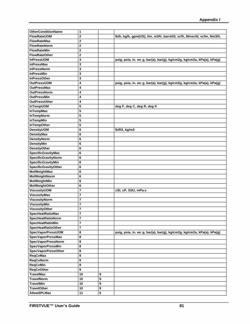
Appendix I
FIRSTVUE™ User’s Guide 81
OtherConditionName 1FlowRateUOM 2 lb/h, kg/h, gpm(US), l/m, m3/h, barrel/d, scfh, Mmscfd, scfm, Nm3/h,
scfdFlowRateMax 2FlowRateNorm 2FlowRateMin 2FlowRateOther 2InPressUOM 3 psig, psia, in. wc g, bar(a), bar(g), kg/cm2g, kg/cm2a, kPa(a), kPa(g)InPressMax 3InPressNorm 3InPressMin 3InPressOther 3OutPressUOM 4 psig, psia, in. wc g, bar(a), bar(g), kg/cm2g, kg/cm2a, kPa(a), kPa(g)OutPressMax 4OutPressNorm 4OutPressMin 4OutPressOther 4InTempUOM 5 deg F, deg C, deg R, deg KInTempMax 5InTempNorm 5InTempMin 5InTempOther 5DensityUOM 6 lb/ft3, kg/m3DensityMax 6DensityNorm 6DensityMin 6DensityOther 6SpecificGravityMax 6SpecificGravityNorm 6SpecificGravityMin 6SpecificGravityOther 6MolWeightMax 6MolWeightNorm 6MolWeightMin 6MolWeightOther 6ViscosityUOM 7 cSt, cP, SSU, mPa.sViscosityMax 7ViscosityNorm 7ViscosityMin 7ViscosityOther 7SpecHeatRatioMax 7SpecHeatRatioNorm 7SpecHeatRatioMin 7SpecHeatRatioOther 7SpecVaporPressUOM 8 psig, psia, in. wc g, bar(a), bar(g), kg/cm2g, kg/cm2a, kPa(a), kPa(g)SpecVaporPressMax 8SpecVaporPressNorm 8SpecVaporPressMin 8SpecVaporPressOther 8ReqCvMax 9ReqCvNorm 9ReqCvMin 9ReqCvOther 9TravelMax 10 9TravelNorm 10 9TravelMin 10 9TravelOther 10 9AllowSPLMax 11 5
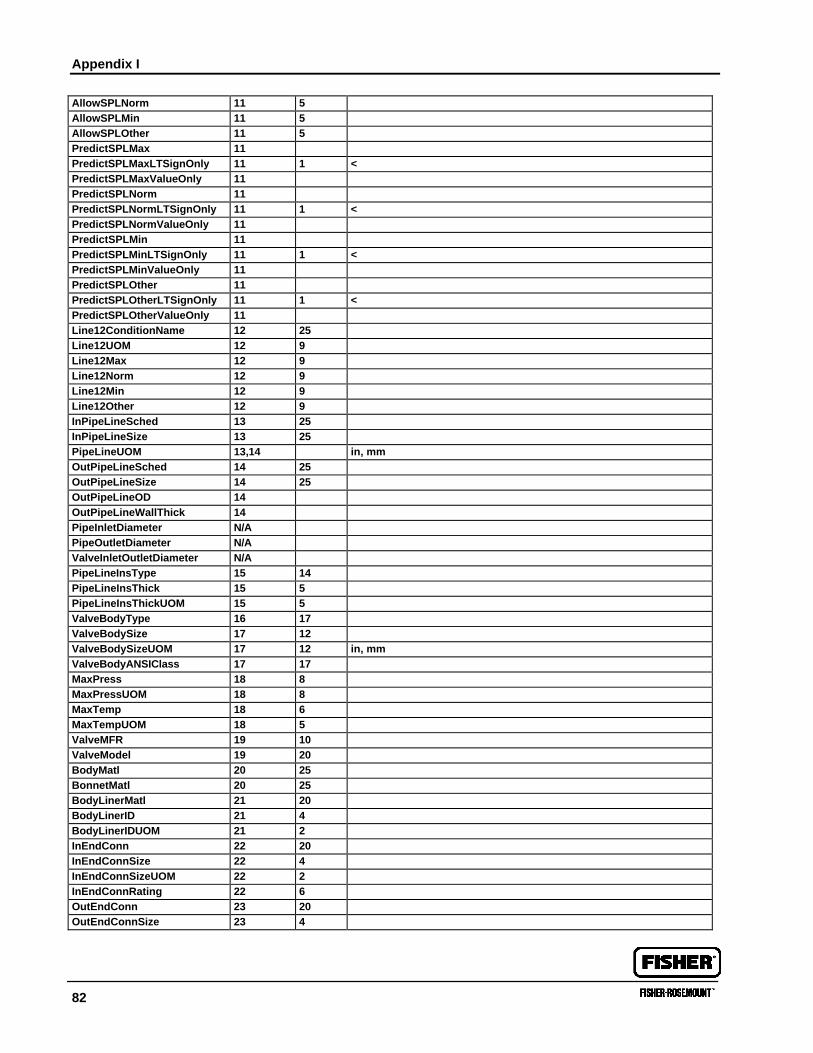
Appendix I
82
AllowSPLNorm 11 5AllowSPLMin 11 5AllowSPLOther 11 5PredictSPLMax 11PredictSPLMaxLTSignOnly 11 1 <PredictSPLMaxValueOnly 11PredictSPLNorm 11PredictSPLNormLTSignOnly 11 1 <PredictSPLNormValueOnly 11PredictSPLMin 11PredictSPLMinLTSignOnly 11 1 <PredictSPLMinValueOnly 11PredictSPLOther 11PredictSPLOtherLTSignOnly 11 1 <PredictSPLOtherValueOnly 11Line12ConditionName 12 25Line12UOM 12 9Line12Max 12 9Line12Norm 12 9Line12Min 12 9Line12Other 12 9InPipeLineSched 13 25InPipeLineSize 13 25PipeLineUOM 13,14 in, mmOutPipeLineSched 14 25OutPipeLineSize 14 25OutPipeLineOD 14OutPipeLineWallThick 14PipeInletDiameter N/APipeOutletDiameter N/AValveInletOutletDiameter N/APipeLineInsType 15 14PipeLineInsThick 15 5PipeLineInsThickUOM 15 5ValveBodyType 16 17ValveBodySize 17 12ValveBodySizeUOM 17 12 in, mmValveBodyANSIClass 17 17MaxPress 18 8MaxPressUOM 18 8MaxTemp 18 6MaxTempUOM 18 5ValveMFR 19 10ValveModel 19 20BodyMatl 20 25BonnetMatl 20 25BodyLinerMatl 21 20BodyLinerID 21 4BodyLinerIDUOM 21 2InEndConn 22 20InEndConnSize 22 4InEndConnSizeUOM 22 2InEndConnRating 22 6OutEndConn 23 20OutEndConnSize 23 4
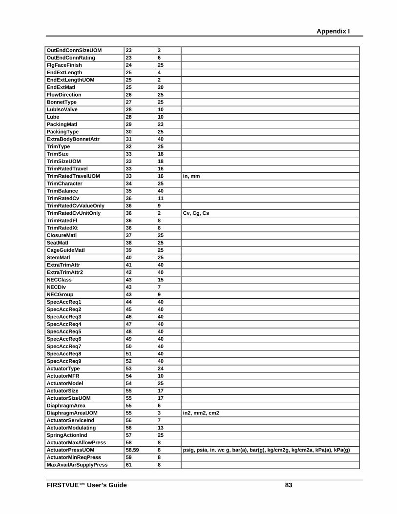
Appendix I
FIRSTVUE™ User’s Guide 83
OutEndConnSizeUOM 23 2OutEndConnRating 23 6FlgFaceFinish 24 25EndExtLength 25 4EndExtLengthUOM 25 2EndExtMatl 25 20FlowDirection 26 25BonnetType 27 25LubIsoValve 28 10Lube 28 10PackingMatl 29 23PackingType 30 25ExtraBodyBonnetAttr 31 40TrimType 32 25TrimSize 33 18TrimSizeUOM 33 18TrimRatedTravel 33 16TrimRatedTravelUOM 33 16 in, mmTrimCharacter 34 25TrimBalance 35 40TrimRatedCv 36 11TrimRatedCvValueOnly 36 9TrimRatedCvUnitOnly 36 2 Cv, Cg, CsTrimRatedFl 36 8TrimRatedXt 36 8ClosureMatl 37 25SeatMatl 38 25CageGuideMatl 39 25StemMatl 40 25ExtraTrimAttr 41 40ExtraTrimAttr2 42 40NECClass 43 15NECDiv 43 7NECGroup 43 9SpecAccReq1 44 40SpecAccReq2 45 40SpecAccReq3 46 40SpecAccReq4 47 40SpecAccReq5 48 40SpecAccReq6 49 40SpecAccReq7 50 40SpecAccReq8 51 40SpecAccReq9 52 40ActuatorType 53 24ActuatorMFR 54 10ActuatorModel 54 25ActuatorSize 55 17ActuatorSizeUOM 55 17DiaphragmArea 55 6DiaphragmAreaUOM 55 3 in2, mm2, cm2ActuatorServiceInd 56 7ActuatorModulating 56 13SpringActionInd 57 25ActuatorMaxAllowPress 58 8ActuatorPressUOM 58.59 8 psig, psia, in. wc g, bar(a), bar(g), kg/cm2g, kg/cm2a, kPa(a), kPa(g)ActuatorMinReqPress 59 8MaxAvailAirSupplyPress 61 8
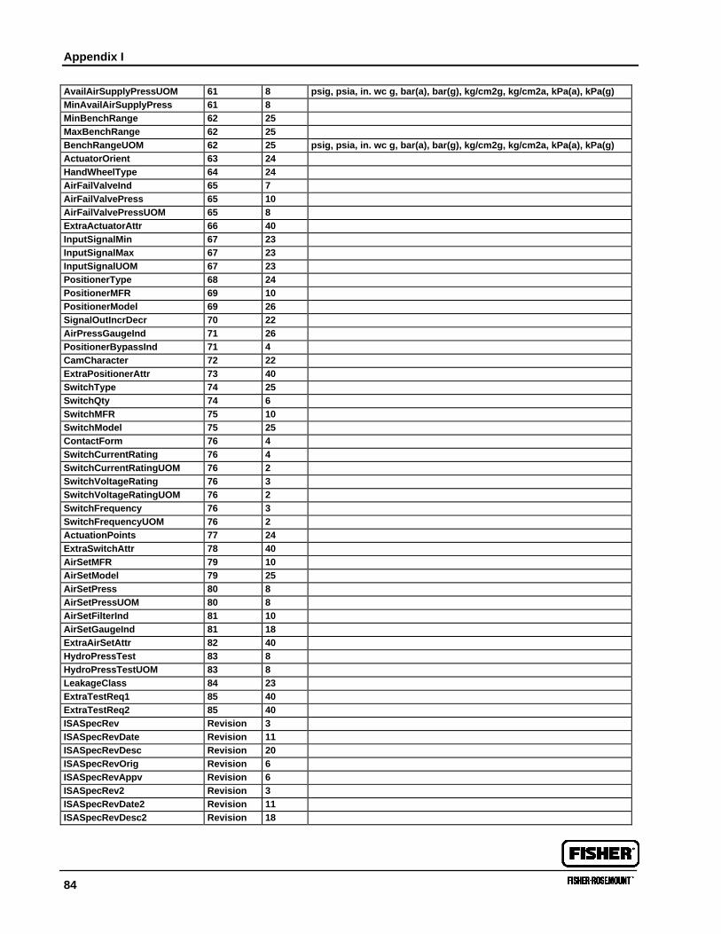
Appendix I
84
AvailAirSupplyPressUOM 61 8 psig, psia, in. wc g, bar(a), bar(g), kg/cm2g, kg/cm2a, kPa(a), kPa(g)MinAvailAirSupplyPress 61 8MinBenchRange 62 25MaxBenchRange 62 25BenchRangeUOM 62 25 psig, psia, in. wc g, bar(a), bar(g), kg/cm2g, kg/cm2a, kPa(a), kPa(g)ActuatorOrient 63 24HandWheelType 64 24AirFailValveInd 65 7AirFailValvePress 65 10AirFailValvePressUOM 65 8ExtraActuatorAttr 66 40InputSignalMin 67 23InputSignalMax 67 23InputSignalUOM 67 23PositionerType 68 24PositionerMFR 69 10PositionerModel 69 26SignalOutIncrDecr 70 22AirPressGaugeInd 71 26PositionerBypassInd 71 4CamCharacter 72 22ExtraPositionerAttr 73 40SwitchType 74 25SwitchQty 74 6SwitchMFR 75 10SwitchModel 75 25ContactForm 76 4SwitchCurrentRating 76 4SwitchCurrentRatingUOM 76 2SwitchVoltageRating 76 3SwitchVoltageRatingUOM 76 2SwitchFrequency 76 3SwitchFrequencyUOM 76 2ActuationPoints 77 24ExtraSwitchAttr 78 40AirSetMFR 79 10AirSetModel 79 25AirSetPress 80 8AirSetPressUOM 80 8AirSetFilterInd 81 10AirSetGaugeInd 81 18ExtraAirSetAttr 82 40HydroPressTest 83 8HydroPressTestUOM 83 8LeakageClass 84 23ExtraTestReq1 85 40ExtraTestReq2 85 40ISASpecRev Revision 3ISASpecRevDate Revision 11ISASpecRevDesc Revision 20ISASpecRevOrig Revision 6ISASpecRevAppv Revision 6ISASpecRev2 Revision 3ISASpecRevDate2 Revision 11ISASpecRevDesc2 Revision 18
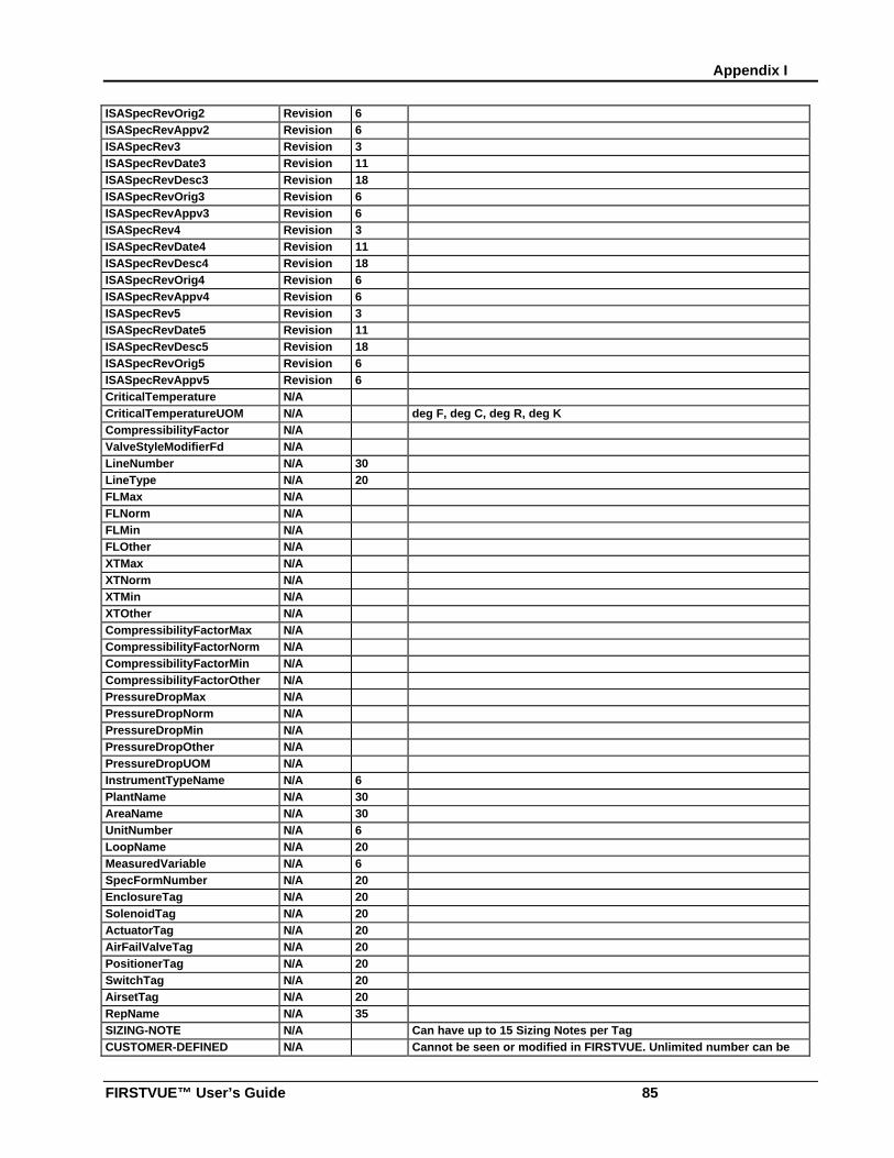
Appendix I
FIRSTVUE™ User’s Guide 85
ISASpecRevOrig2 Revision 6ISASpecRevAppv2 Revision 6ISASpecRev3 Revision 3ISASpecRevDate3 Revision 11ISASpecRevDesc3 Revision 18ISASpecRevOrig3 Revision 6ISASpecRevAppv3 Revision 6ISASpecRev4 Revision 3ISASpecRevDate4 Revision 11ISASpecRevDesc4 Revision 18ISASpecRevOrig4 Revision 6ISASpecRevAppv4 Revision 6ISASpecRev5 Revision 3ISASpecRevDate5 Revision 11ISASpecRevDesc5 Revision 18ISASpecRevOrig5 Revision 6ISASpecRevAppv5 Revision 6CriticalTemperature N/ACriticalTemperatureUOM N/A deg F, deg C, deg R, deg KCompressibilityFactor N/AValveStyleModifierFd N/ALineNumber N/A 30LineType N/A 20FLMax N/AFLNorm N/AFLMin N/AFLOther N/AXTMax N/AXTNorm N/AXTMin N/AXTOther N/ACompressibilityFactorMax N/ACompressibilityFactorNorm N/ACompressibilityFactorMin N/ACompressibilityFactorOther N/APressureDropMax N/APressureDropNorm N/APressureDropMin N/APressureDropOther N/APressureDropUOM N/AInstrumentTypeName N/A 6PlantName N/A 30AreaName N/A 30UnitNumber N/A 6LoopName N/A 20MeasuredVariable N/A 6SpecFormNumber N/A 20EnclosureTag N/A 20SolenoidTag N/A 20ActuatorTag N/A 20AirFailValveTag N/A 20PositionerTag N/A 20SwitchTag N/A 20AirsetTag N/A 20RepName N/A 35SIZING-NOTE N/A Can have up to 15 Sizing Notes per TagCUSTOMER-DEFINED N/A Cannot be seen or modified in FIRSTVUE. Unlimited number can be
used.
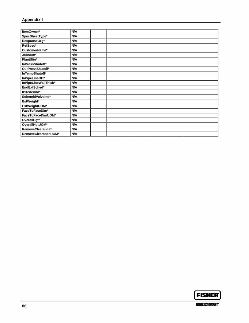
Appendix I
86
ItemOwner* N/ASpecSheetType* N/AResponseOrg* N/ARefSpec* N/ACustomerName* N/AJobNum* N/APlantSite* N/AInPressShutoff* N/AOutPressShutoff* N/AInTempShutoff* N/AInPipeLineOD* N/AInPipeLineWallThick* N/AEndExtSched* N/AIPXcderInd* N/ASolenoidValveInd* N/AEstWeight* N/AEstWeightUOM* N/AFaceToFaceDim* N/AFaceToFaceDimUOM* N/AOverallHgt* N/AOverallHgtUOM* N/ARemoveClearance* N/ARemoveClearanceUOM* N/A