Direct photon interferometry D.Peressounko RRC “Kurchatov Institute”
Upload
august-shieldsCategory
view
219download
1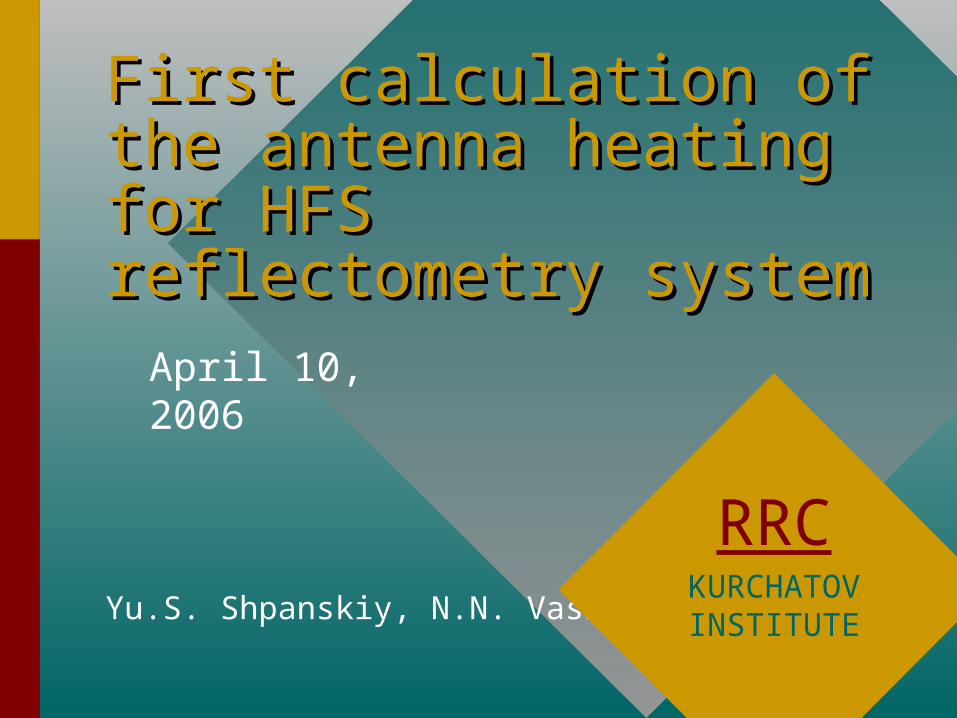
First calculation of the First calculation of the antenna heating for HFS antenna heating for HFS reflectometry systemreflectometry system
Yu.S. Shpanskiy, N.N. Vasiliev
RRCKURCHATOVINSTITUTE
April 10, 2006

Object of the AnalysesObject of the Analyses
In the reactor conditions nuclear heating of the waveguides and antenna for HFS reflectometry will take place.
Three ways of these components cooling could be designed:- water cooling;- thermal contact with blanket modules;- radiation cooling.
First two ways seems problematic.
So it is necessary to carry out thermal and mechanical analyses of waveguides and antenna for HFS reflectometry system in order to understand whether its radiation cooling is possible in these conditions.

View of the waveguides and View of the waveguides and antennaantenna

Blanket cross-sectionBlanket cross-section

Antenna HornAntenna Horn

Emissivities of some elementsEmissivities of some elements
From handbook «Refractory elements and alloys» (in Russian)R.B. Kotelnikov, S.N. Bashlykov, Z.G. Galiakbarov, A.I. Kashtanov
Em
issiv
ity
Temperature, oC
Heat Generation Rate in AntennaHeat Generation Rate in Antenna
D.V. Markovskiy «Calculation of the waveguide nuclear heating
in the gap between blanket modules of the ITER»
Heat
gen
era
tion
rate
, W
/cm
3
Distance from the first wall, cm

Heat Generation Rate in Heat Generation Rate in AntennaAntenna
Figure 2.2.1.2-3 Nuclear Heating Rate in the Shield BlockFrom 2004 DDD 1.6 Blanket, Section 2.2.1.2

One Dimensional estimationsOne Dimensional estimations
a
b
T q
Tokr
4 273
q – heat flux from the antenna surface, W/m2
Tokr – ambient temperature, K
oC

One Dimensional calculationsOne Dimensional calculationsTemperature vs emissivity
Tem
pera
ture
, oC
Emissivity

2-D Model2-D Model

2-D Model. Results of Thermal 2-D Model. Results of Thermal analysisanalysis
Emissivity = 1Emissivity = 1

2-D Model. Results of Thermal 2-D Model. Results of Thermal analysisanalysis
Emissivity = 0.5Emissivity = 0.5

2-D Model. Results of Thermal 2-D Model. Results of Thermal analysisanalysis
Emissivity = 0.2Emissivity = 0.2

3-D Model of the Antenna Horn3-D Model of the Antenna Horn

3-D Mesh of the Antenna Horn 3-D Mesh of the Antenna Horn ModelModel

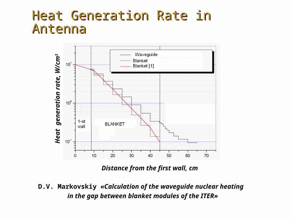
Results of thermal analysis.Results of thermal analysis.Molybdenum Horn. Molybdenum Horn. Emissivity = 1

Results of thermal analysis.Results of thermal analysis.SS Horn. SS Horn. Emissivity = 1

Results of thermal analysis.Results of thermal analysis.Molybdenum Horn. Molybdenum Horn. Emissivity = 0.5

Results of thermal analysis.Results of thermal analysis.SS Horn. SS Horn. Emissivity = 0.5
Results of thermal analysis.Results of thermal analysis.Molybdenum Horn. Molybdenum Horn. Emissivity = 0.2

Results of thermal analysis.Results of thermal analysis.SS Horn. SS Horn. Emissivity = 0.2

Results of thermal analysis.Results of thermal analysis.Molybdenum Horn. Molybdenum Horn. Emissivity = 0.1

Results of thermal analysis.Results of thermal analysis.SS Horn. SS Horn. Emissivity = 0.1

Results of mechanical analysis.Results of mechanical analysis.Molybdenum Horn. Equivalent (von Mises) Molybdenum Horn. Equivalent (von Mises)
Stress. Stress. Emissivity = 0.1

Results of mechanical analysis.Results of mechanical analysis.Molybdenum Horn. Displacement. Molybdenum Horn. Displacement. Emissivity
= 0.1

Results of mechanical analysis.Results of mechanical analysis.Molybdenum Horn. Displacement. Molybdenum Horn. Displacement. Emissivity
= 0.1

ConclusionsConclusions
• First analyses of the antenna heating for HFS First analyses of the antenna heating for HFS reflectometry systemreflectometry system were were carried outcarried out..
• Maximum temperatures Maximum temperatures in 3-D calculations in 3-D calculations are are the followingthe following::- - MoMo structure, emissivity = structure, emissivity = 0.10.1 => T = => T = 715715 ooC;C;- SS structure, emissivity = - SS structure, emissivity = 0.10.1 => T = => T = 782782 ooCC..
• Investigations on the possibility of the Emissivity Investigations on the possibility of the Emissivity value increase in the reactor conditions are value increase in the reactor conditions are needed.needed.

Possible ways of Emissivity Possible ways of Emissivity increaseincrease
1. Coating.2. Making of artificial roughness.
1
)11
(1
F
smoothrough
F – roughness factor;
surfacerough
surfacesmoothF
0 0.2 0.4 0.6 0.8 10
0.2
0.4
0.6
0.8
11
0.1
rough F( )
10 F
ro
ug
h
F
S.C. Agababov, V.S. AgababovThe influence of geometrical relief of solid body surface at its radiation proprrties.1-st Russian national conference on heat transfer. Moscow. 1994. PP 13-16.
smooth = 0.1


![Elements of Vasiliev theory - MPG.PuRepubman.mpdl.mpg.de/pubman/item/escidoc:1945320/component/esci… · arXiv:1401.2975v1 [hep-th] 13 Jan 2014 Elements of Vasiliev theory V.E.Didenko∗](https://static.fdocuments.us/doc/165x107/5aa8a4ed7f8b9a9a188bda5c/elements-of-vasiliev-theory-mpg-1945320componentesciarxiv14012975v1-hep-th.jpg)