Firewalls and post-earthquake fire resistance of ...379085/UQ379085_OA.pdf · Firewalls and...
14
Firewalls and post-earthquake fire resistance of reinforced- concrete frames & 1 Behrouz Behnam PhD Assistant Professor, School of Civil Engineering, Amirkabir University of Technology, Tehran, Iran; also Associate Researcher in Structural Retrofit Research Group, School of Civil Engineering, the University of Queensland, Brisbane, Australia & 2 Hamid Reza Ronagh PhD Senior Lecturer, School of Civil Engineering, the University of Queensland, Brisbane, Australia 1 2 Post-earthquake fire (PEF) contributes significantly to loss of life and property following large earthquakes in urban regions. In the absence of adequate PEF provisions in the codes and criteria, an investigation is performed on a reinforced concrete portal frame, divided into two unequal parts by a firewall. Acknowledging that firewalls could break down after earthquake, three fire exposure scenarios are assumed: only the left part exposed, only the right part exposed and the entire frame exposed. In the first two scenarios, the firewall remains intact, whereas in the third it is assumed to be broken down. The building is first pushed to displacement corresponding to the life safety level of performance based on FEMA 356 code. Then, using a natural fire curve, fire analysis is performed. Fire-alone analysis is performed to provide a point of reference. No failure occurs in any of the fire-alone scenarios, or when exposing the smaller part of the building to the PEF. In contrast, exposing the larger part and the entire frame to PEF makesthe frame fail at around 50 min and 25 min, respectively. This shows the importance of firewalls to reduce vulnerability of reinforced concrete buildings in case of PEF. The approach used allows designers to choose the position and configuration of firewallsto best protect a building against PEF. Notation A peak ground acceleration A external walls external wall area A firewalls firewall area A floor floor area A t total area A v opening area B building response factor b avg thermal properties of the enclosure C seismic coefficient g ground acceleration H section height h c convection heat transfer coefficient h r radiation heat transfer coefficient h Tot convection and radiation heat transfer coefficient h w wall height I importance factor Lp plastic hinge length M moment ˙ q 00 Tot total energy balance q t,d fire load density R building behaviour factor T gas gas temperature T s surface temperature V shear force at base level W total seismic weight of the structure Γ expansion factor Δ mid-span deflection Θ max maximum temperature ϕ curvature 1. Introduction Large earthquakes can bring about two types of damage to urban structures: primary and secondary (Calvi et al., 2006). The primary damages result from direct application of earth- quake loads on structures, whereas secondary damages are indirectly caused by some secondary phenomenon being trig- gered by the earthquake, such as liquefaction and tsunamis. One of the most problematic secondary type damage-inducing 20 Structures and Buildings Volume 169 Issue SB1 Firewalls and post-earthquake fire resistance of reinforced-concrete frames Behnam and Ronagh Proceedings of the Institution of Civil Engineers Structures and Buildings 169 January 2016 Issue SB1 Pages 20–33 http://dx.doi.org/10.1680/stbu.14.00031 Paper 1400031 Received 24/03/2014 Accepted 12/05/2015 Published online 11/07/2015 Keywords: buildings, structures & design/concrete structures/ disaster engineering ICE Publishing: All rights reserved Downloaded by [ University of Queensland - Central Library] on [09/05/16]. Copyright © ICE Publishing, all rights reserved.
Transcript of Firewalls and post-earthquake fire resistance of ...379085/UQ379085_OA.pdf · Firewalls and...

Firewalls and post-earthquakefire resistance of reinforced-concrete frames&1 Behrouz Behnam PhD
Assistant Professor, School of Civil Engineering, Amirkabir University ofTechnology, Tehran, Iran; also Associate Researcher in StructuralRetrofit Research Group, School of Civil Engineering, the University ofQueensland, Brisbane, Australia
&2 Hamid Reza Ronagh PhDSenior Lecturer, School of Civil Engineering, the University ofQueensland, Brisbane, Australia
1 2
Post-earthquake fire (PEF) contributes significantly to loss of life and property following large earthquakes in urban
regions. In the absence of adequate PEF provisions in the codes and criteria, an investigation is performed on a
reinforced concrete portal frame, divided into two unequal parts by a firewall. Acknowledging that firewalls could
break down after earthquake, three fire exposure scenarios are assumed: only the left part exposed, only the right
part exposed and the entire frame exposed. In the first two scenarios, the firewall remains intact, whereas in the third
it is assumed to be broken down. The building is first pushed to displacement corresponding to the life safety level of
performance based on FEMA 356 code. Then, using a natural fire curve, fire analysis is performed. Fire-alone analysis
is performed to provide a point of reference. No failure occurs in any of the fire-alone scenarios, or when exposing
the smaller part of the building to the PEF. In contrast, exposing the larger part and the entire frame to PEF makes the
frame fail at around 50 min and 25 min, respectively. This shows the importance of firewalls to reduce vulnerability
of reinforced concrete buildings in case of PEF. The approach used allows designers to choose the position and
configuration of firewalls to best protect a building against PEF.
NotationA peak ground accelerationAexternal walls external wall areaAfirewalls firewall areaAfloor floor areaAt total areaAv opening areaB building response factorbavg thermal properties of the enclosureC seismic coefficientg ground accelerationH section heighthc convection heat transfer coefficienthr radiation heat transfer coefficienthTot convection and radiation heat transfer coefficienthw wall heightI importance factorLp plastic hinge lengthM momentq̇00Tot total energy balance
qt,d fire load densityR building behaviour factorTgas gas temperatureTs surface temperatureV shear force at base levelW total seismic weight of the structureΓ expansion factorΔ mid-span deflectionΘmax maximum temperatureϕ curvature
1. IntroductionLarge earthquakes can bring about two types of damage tourban structures: primary and secondary (Calvi et al., 2006).The primary damages result from direct application of earth-quake loads on structures, whereas secondary damages areindirectly caused by some secondary phenomenon being trig-gered by the earthquake, such as liquefaction and tsunamis.One of the most problematic secondary type damage-inducing
20
Structures and BuildingsVolume 169 Issue SB1
Firewalls and post-earthquake fireresistance of reinforced-concrete framesBehnam and Ronagh
Proceedings of the Institution of Civil EngineersStructures and Buildings 169 January 2016 Issue SB1Pages 20–33 http://dx.doi.org/10.1680/stbu.14.00031Paper 1400031Received 24/03/2014 Accepted 12/05/2015Published online 11/07/2015Keywords: buildings, structures & design/concrete structures/disaster engineering
ICE Publishing: All rights reserved
Downloaded by [ University of Queensland - Central Library] on [09/05/16]. Copyright © ICE Publishing, all rights reserved.

phenomena is post-earthquake fire (PEF). Historical recordshave proved that PEFs are devastating and, if not controlled,can swiftly spread to large areas and lead to a conflagration(Mohammadi and Alysian, 1992; Mousavi et al., 2008). This ismainly because urban structures are not designed to withstandPEF loads (Borden, 1996). Hence, when a partially damagedstructure is faced with the PEF load, it collapses more rapidlythan the intact structure (Chen et al., 2004). Thus, further strin-gent requirements need to be considered in either the earth-quake codes or the fire codes for those structures that mayexperience PEF. To do this, the first step is to scrutinise thestructural behaviour under PEF loads.
Performance-based seismic analysis is used to evaluate thestructural behaviour under earthquake loads where variousperformance objectives are defined. Normally, very importantstructures such as museums and governmental buildings aredesigned to sustain negligible damage if loaded with the designearthquake. Important structures such as hospitals and edu-cational centres are designed to sustain minor damage, whiletheir ability to function (serviceability) has to be maintainedafter the earthquake. On the other hand, ordinary structuressuch as residential and commercial buildings are designed tosustain notable damage. However, their integrity should be main-tained after the design earthquake, meaning that they shouldnot collapse before inhabitants are all evacuated from thebuilding safely. In FEMA 356 (FEMA, 2000), very importantstructures are designed at the operational (O) level of perform-ance; important structures are designed at the immediate occu-pancy (IO) level and ordinary structures are designed for thelife safety (LS) level of performance. To quantify the damagesustained by structures, lateral drift is used as an index.Structures designed for O and IO levels of performance sustainalmost no permanent drift, while the transient drift is limitedto 1%. By contrast, the drift value in buildings designed for LSlevel of performance should not exceed 2%. At the LS level ofperformance the collapse of light internal walls, such aspartitions, is allowed, but it is strongly recommended that theexterior walls should permanently be connected to the struc-tural members in order to withstand the effects of earthquakemovements (ASCE, 2013).
Performance-based fire analysis is used to involve all factorsthat can have an effect on a fire’s progress in a compartment.The factors should be adequately informative, including thematerials of construction, the location of the compartment ina building, the heat transfer mechanism, the load ratio, the posi-tion of openings, the availability of active and passive firemeasures such as sprinkler systems and rescue teams (ACI216;ACI, 2006; Meacham and Custer, 2002). The information isused to simulate a more realistic fire. Fire resistance of thestructural members is then calculated (Franssen et al., 2009;Kodur et al., 2012), and expressed as the time up to which thestructural integrity is maintained against the applied fire loads(Kodur and Dwaikat, 2007).
It is clear that the structural performance is less favourablewhen a fire starts after an earthquake. In such a case, thedamage resulted from the earthquake shall be considered as theinitial state for the subsequent fire. The earthquake damage canbe two fold: the residual deformation and the degradation instrength and/or stiffness (Zaharia and Pintea, 2009). Inreinforced concrete (RC) structures with a ductile behaviour,the mentioned damages can cause tensile cracking, removal ofcover and compressive crushing. A typical moment–curvaturerelation can then be idealised into separate stages of pre-cracking of concrete, post cracking, yielding of steel reinforce-ment and concrete crushing in compression (Kwak and Kim,2002). Experimental tests have demonstrated that tensile crack-ing has almost no effect on the PEF resistance, whereas majorcracking and removal of cover can considerably decrease thePEF resistance (Ervine et al., 2012). It is worth mentioning thatthe damage area in RC structures is mostly localised at andaround the critical sections, while at other locations concretemight be only lightly cracked, even in the worst seismic scen-ario. Damaged areas lose their stiffness as concrete cracks andspall off and the reinforcement yields. The result is that thecross-sections located within a certain length, termed the‘plastic hinge length’, deform plastically to collapse. The plastichinge length can be calculated by way of empirical and numeri-cal equations presented in the past by other researchers (Baeand Bayrak, 2008; Park and Paulay, 1975; Roh et al., 2012).For example, the plastic hinge length (LP) based on Park andPaulay’s (1975) formula suggests using LP= 0·5H where H isthe section height. The tests results confirm that, at the IO levelof performance, only minor cracking would occur in the struc-tural members; therefore, no change exists in the structuralgeometry or material properties after the earthquake. At the LSperformance level, however, spalling of the cover of rebarswould occur (Behnam et al., 2015; FEMA, 2000; Meada andKang, 2009; Nakano et al., 2004; Sharma et al., 2012).
2. Previous studiesPost-earthquake fire research has received more attention sincethe 9/11 terrorist attack to the Twin Towers (Chen et al., 2004;Mousavi et al., 2008). In macro scale, the regional effects ofPEF mostly on urban infrastructures are considered, includingbuildings density, seismic intensity, wind velocity and avail-ability of the rescue teams (Borden, 1996; Collier, 2005;Ghoreishi and Sutlan, 2009; Lee et al., 2004; Nasirzadehet al., 2009; Robertson and Mehaffey, 2000; Scawthorn, 2008;Scawthorn et al., 2005; Taylor, 2003; Wellington LifelinesGroup, 2002; Xie and Ren, 2004; Zolfaghari et al., 2009). Inmicro scale, the investigations are mostly concentrated on par-tially seismic-damaged structures exposed to fire. Severalresearchers have studied protected and unprotected steel struc-tures (Alderighi and Salvatore, 2009; Braxtan and Pessiki,2011; Pucinotti et al., 2011; Ryder et al., 2002; Tomecek andMilke, 1993; Wang and Li, 2009; Zaharia and Pintea, 2009).In one study, Della Corte et al. (2003) showed that the driftratio has a significant effect on the PEF resistance of
21
Structures and BuildingsVolume 169 Issue SB1
Firewalls and post-earthquake fireresistance of reinforced-concrete framesBehnam and Ronagh
Downloaded by [ University of Queensland - Central Library] on [09/05/16]. Copyright © ICE Publishing, all rights reserved.

moment-resisting steel frames (MRSF). Zaharia and Pintea(2009) also performed a numerical investigation on twoMRSFs, designed for two different return periods of earth-quake: 2475 years and 475 years. Their investigation showedthat the fire resistance of the structures, considering theirdeformed state under earthquake, is lower than that of struc-tures that do not have any history of deformation prior to theapplication of fire. Another study was performed by theauthors (Behnam and Ronagh, 2015) on MRSFs designed fortwo different performance levels IO and LS and exposed toPEF loads. Alderighi and Salvatore (2009) performed anumerical investigation for composite steel frames with circularconcrete-filled columns. A series of thermo-mechanical analysesunder different fire exposure times were performed in order tocategorise the potential structural failure by the state of stressat the critical cross-sections. Consequently, the influence ofvarious restraining conditions on the performed thermo-mechanical analyses was investigated. They then proposed amethodology to estimate the amounts of axial restraint given tothe exposed beams. Faggiano and co-workers (Faggiano andGregorgio, 2010; Faggiano and Mazzolani, 2011) investigatedsteel structures exposed to PEF. Based on the FEMA 356 pro-cedure, Faggiano and co-workers developed a method called
robustness assessment for evaluating the performance of build-ings subjected to earthquake, and for suggesting fire perform-ance levels for various conditions of fire. The proposedprocedure was then demonstrated with regard to a particularclass of steel structures. The authors (Behnam and Ronagh,2013b) have also investigated the effect of a vertically travellingPEF on tall MRSFs while various fire scenarios, concurrent fireand delayed fire were considered (Figure 1). The results showedthat exposing the frame to the delayed fire leads to different fireresistance than for a concurrent fire.
A number of researchers have evaluated the performance ofRC structures in a PEF scenario. Mostafaei and Kabeyasawa(2010) carried out a PEF analysis on a RC structure previouslydamaged by an equivalent Kobe 1995 earthquake on a shakingtable. Then, using a method called axial-shear–flexure inter-action (ASFI) (Kabeyasawa and Mostafaei, 2007), the degra-dation of the concrete compressive strength was accounted for.The results of the ASFI method were subsequently used forcomputing the PEF resistance of the structure, showing thatdamaged structures are more vulnerable to fire loads thanintact structures. An experimental test was conducted byErvine et al. (2011) on a RC element subjected to gravity loads
Figure 1. Vertically travelling post-earthquake fire (Behnam andRonagh, 2013b)
22
Structures and BuildingsVolume 169 Issue SB1
Firewalls and post-earthquake fireresistance of reinforced-concrete framesBehnam and Ronagh
Downloaded by [ University of Queensland - Central Library] on [09/05/16]. Copyright © ICE Publishing, all rights reserved.
followed by fire load and in order to find the effect of thecracked and/or damaged sections on the thermal propagationinside the section. The results showed that minor tensile crack-ing would not significantly change the heat penetration insidethe section. However, exposing the rebars directly to fire (e.g.in the case of crushing of the cover) changes both the thermaland the structural behaviour of the specimen considerably.Another study was undertaken by Sharma et al. (2012) on thefire resistance of an earthquake-damaged RC frame. A nearlyfull-scale frame was first loaded by the relevant gravity loadsand then subjected to a cyclic lateral load, based on the Indianstandard, in a quasi-static fashion (BIS, 2005). The load-control mode was considered to meet 2% drift, correspondingto the LS performance level. The cracks’ widths were thenobserved using optical tools, non-destructive tests and ultra-sound. A computational analysis was also performed using thefinite-element method with Abaqus (2008) to compare the testand the analytical results. The results showed a good con-formity with FEMA 356 descriptive definitions of damagelevels at various performance levels, such as IO and LS.Consequently, the PEF analysis was performed using bothnumerical and experimental methods. The results showed thatthe frame did not collapse, even after 60 min of exposure tofire. Yet no comparison was made between the results of thefire-alone situation and those of PEF.
The present authors have also investigated the response of RCstructures subjected to PEF in several studies (Behnam andRonagh, 2013a, 2013c, 2014b; Ronagh and Behnam, 2012).They used a sequential analysis in order to simulate a PEF scen-ario. Using the results of previously conducted tests by Sharmaet al. (2012), Meada and Kang (2009), Nakano et al. (2004) andthe tests conducted by the authors (Behnam et al., 2015) as wellas prescriptive definition of damage stipulated by FEMA 356,they considered the state of damage resulted from the designearthquake in their studies. The results showed that there wereminor differences between the fire resistances of the fire-alonesituation and the PEF resistance of the frames pushed to arriveat the IO level of performance. However, a major difference wasobserved between the fire resistance and the PEF resistance ofthe frames pushed to arrive at the LS level of performance. Theresults also showed that subjecting only the beams to fire leadsto a higher reduction in the fire resistance compared to exposingonly the columns to fire. In separate studies, they then proposeddifferent engineering solutions in order to improve the PEFresistance of existing structures and those that are yet to bedesigned (Behnam and Ronagh, 2013d, 2013f, 2014a).
Aligned with the studies mentioned and based on the previouswork performed by the authors, an investigation is carried outhere on an RC structure designed for the LS level of perform-ance, which contains a firewall and is subjected to PEF. Theinvestigation includes two separate assumptions: when firewallsremain intact or when they break down following the earth-quake and prior to the PEF.
3. Load sequencesModelling of PEF in a structure is a complex process, as thestructure has to be loaded in steps. The first step of modellingis the application of gravity loads, which is followed by thesecond step, the loading of seismic loads and finally by thethird step, the application of fire loads. In the absence of finite-element software being available that is capable of performinga coupled analysis (which can consider seismic analysis and asubsequent fire, while allowing for the variation of materialproperties at elevated temperature), the authors (Behnam andRonagh, 2013a, 2013c, 2014b; Ronagh and Behnam, 2012)used a method they termed ‘sequential analysis’ as a functionaltool to simulate a PEF analysis. In order to perform theseismic analysis, SAP2000 software is employed (SAP2000-V14; SAP2000, 2002). Then, a function is written whereby theresults of the seismic analysis are transported into the secondsoftware – Safir (Franssen, 2005) – which performs the struc-tural fire analysis. As SAP2000 is compatible with FEMA 356,the damage levels including the states of the plastic hinges andtheir locations in all the members can be fully monitored.Then, based on the prescriptive definition of damage state sti-pulated in FEMA 356, as well as experimental tests conductedby Meada and Kang (2009), Nakano et al. (2004) andBehnam et al. (2014), results of the pushover analysis are justi-fied. For instance, at the IO level of performance only minorcracking would occur with no significant effect on the PEFresistance. At the LS level of performance, by contrast, it isexpected that the cover of concrete would be spalled in thevicinity of the plastic hinges created. This information is vitalwhere the fire frontiers of the cross-sections are introduced bySafir. As plasticity of materials is included in the Safirprogram, the degradation of strength and stiffness as a resultof lateral loads are therefore considered. It is worth mentioningthat, athough SAP2000 and Safir use different methods foranalysing the models, the results are not necessarily differentas well. By defining several subsequent lumped plastic hingesin the frames created by SAP2000, it is possible to clarifywhich parts of an element have gone beyond the elastic part ofthe pushover diagram. The authors have already controlledand observed that only those parts of the elements located inthe proximity of the joints undergo plastic deformations whilethe rest remain in the elastic part of the pushover analysis(Behnam and Ronagh, 2013e).
As previously mentioned, for the seismic analysis, non-linearstatic analysis (known as pushover analysis) is used, which iswell accepted as a practical analysis model, and to a greatextent can meet the structural analysis needs (Krawinkler andSeneviratna, 1998). The model is based on the fundamentalassumption that the structural response can be attributedto the response of an equivalent single degree-of-freedom(SDOF) system. Although this assumption is not completelycorrect, there is a large consensus on the use of the model as arational tool to estimate the maximum seismic response ofmulti degree-of-freedom (MDOF) structures, if the response of
23
Structures and BuildingsVolume 169 Issue SB1
Firewalls and post-earthquake fireresistance of reinforced-concrete framesBehnam and Ronagh
Downloaded by [ University of Queensland - Central Library] on [09/05/16]. Copyright © ICE Publishing, all rights reserved.

the structure is governed by a single mode (Azimi et al., 2009;Bagchi, 2004; Chopra and Goel, 2004; Fajfar, 2000; Han andChopra, 2006; Kalkan and Chopra, 2011; Mwafy andElnashai, 2001). In conventional pushover analysis, using aspecific load pattern, the structure is pushed to arrive at a dis-placement called the target displacement. The target displace-ment serves as an estimate of the global displacement that thestructure is expected to experience in a design earthquake,often represented by the roof displacement at the centre ofmass of the roof. From a different viewpoint, the finite-element(FE) model is the most capable model for the plasticity analy-sis of RC members. Using an FE model, the material plasticityin steel and concrete can be accounted for (Godat, 2008; Linet al., 2009; Zhao and Sritharan, 2007). A beam element isthen created by integration of a series of sections along theelement length. The constitutive relation of the section is notspecified explicitly, but is derived by integration of the responseof the fibres, which follow the uniaxial stress–strain relation ofthe particular material. Using the constitutive material stress–strain relationship, the M–ϕ curve is generated, where M and ϕstand for moment and curvature, respectively. It is evident thatconcrete can be subdivided into two parts, the core, which isconfined by the longitudinal reinforcement and shear reinforce-ment, and the cover, which is unconfined (Lee and Mosalam,2004).
For the fire analysis, several points should be taken intoconsideration, which are the effect of fire on the materialscharacteristics, the design fire and the heat transfer. It is uni-versally accepted that the materials’ thermal and mechanicalcharacteristics change significantly when subjected to hightemperature. The temperature may then produce thermalstresses (Kwasniewski, 2011). In composite materials suchas RC, the thermal characteristics of concrete and rebar arenot identical and, hence, differential thermal stresses can speedup the degradation. Concrete is not as heat conductive asreinforcement bars are, and as such would act as insulationthat protects the reinforcement bars from heat. However, therebars would directly be exposed to fire after an earthquake.In that case, the heat resulted from the high temperature canmore quickly penetrate inside the cross-section and speed upthe degradation in strength. Often, the concrete is no longerconsidered a structurally relevant material beyond around500°C. In rebar, the mechanical properties start decreasingsignificantly between 300°C (elastic modulus) and 500°C (com-pressive strength) (Bamonte et al., 2008; Youssef and Moftah,2007). It is also worth mentioning that the thermal spalling ofconcrete cover under fire exposure plays an important role andcan significantly decrease the load bearing of the structures(Debicki et al., 2012; Smith, 1991). This is because, after spal-ling, the boundaries of the concrete members change in such away the rebars are directly heated up, and thus the strength ofthe member decreases faster (Kodur et al., 2004). In addition,the cross-section of the member reduces, hence reducing theflexural rigidity. Thermal spalling, however, is more important
in elements with more than 4–5 cm cover (Majorana et al.,2010) or those made of high-strength concrete (Kodur, 2005)containing particles smaller than the cement grains (microsilica, for example) and a moisture content more than 3–4%(Hertz, 2003; Hertz and Sørensen, 2005). For the elementsused in this study, which are made from normal strength con-crete with a cover of 4·0 cm and moisture of 2%, thermal spal-ling is not considered.
As per the design fire, the phases of a fire can be divided intothree parts, namely, ignition (pre-flashover), heating phase andthe cooling phase, as shown in Figure 2. It is worth noting thatthe heating phase duration depends on various factors, mostimportant of which are thermal inertia of the combustiblematerials (called fuel-controlled) and availability of oxygen(called ventilation-controlled) (Karlsson and Quintiere, 1999).For specific amounts of combustible materials inside a com-partment, the openings determine whether the heating phase isfuel-controlled or ventilation-controlled. The heating phase isthe most serious part of a fire in terms of structural failure,because if the fire cannot be suppressed before flashover, struc-tural elements must have adequate fire resistance to preventany collapse (Denoël, 2007). When more than 70% of combus-tible materials are consumed or there is no longer adequateoxygen, the fire diminishes and the temperatures decline overtime. Structural behaviour in the cooling phase is important,particularly in the joints. During the decay phase, extensivetensile forces are created in the axially restrained beams, so arapid collapse might occur. This is related to the fact that com-posite materials do not have similar thermal characteristics,and this leads to different rates of temperature loss (Hanus,2010). Experimental tests and observations of real fires haveconfirmed the high possibility of structural failure during thecooling phase (Bailey et al., 1996).
Based on the above fundamental definitions, a design fire scen-ario can then be proposed. The design fire scenario shouldcover various attributes of a compartment, such as the type
Tem
pera
ture
Flashover
Ignition Heating Cooling
Time
Figure 2. Development phases in a fire
24
Structures and BuildingsVolume 169 Issue SB1
Firewalls and post-earthquake fireresistance of reinforced-concrete framesBehnam and Ronagh
Downloaded by [ University of Queensland - Central Library] on [09/05/16]. Copyright © ICE Publishing, all rights reserved.
of occupancy, the amounts of combustible materials and thesize and location of openings. There are two main fire curves,which are commonly employed in structural fire engineering:standard (nominal) fire curves and natural fire curves(Buchanan, 2001). Here, the natural fire curve recommendedby the Eurocode 1 Annex A (BSI, 2002) is used while noactive measures (on-site or off-site facilities) are considered.
The simulation of a fire in a compartment is a complexprocess, which is performed through two parts, the method bywhich the temperature produced by the fire is calculated – asexplained above – and quantifying the temporal and spatialdistributions of the accounted for temperature, which is appliedto the structural elements – known as boundary conditions.Finally, the structural behaviour under elevated temperatures isevaluated (Lennon and Moore, 2003; Torero, 2012). Afterdeciding on the method of accounting for the temperature pro-duced by the source of fire (Tgas), the problem of heat transferreduces to differential equations with certain boundary con-ditions that allow the calculation of Ts at the surface of thestructural elements and the transfer of heat through the elementto the other side. The heat is mostly transferred through one ormore of the basic laws, namely, convection, radiation and con-duction (Denoël, 2007; Drysdale, 2011). While transfer of heatby convection requires a medium, transfer of heat by radiationneeds no material between the fire source and the solid(Torero, 2012). Although radiation has a predominant role inheat transfer from the source of fire to the surface of the solid(Purkiss, 1996), the role of convection cannot be entirelyignored (Welch et al., 2007). In addition, a fully engulfed com-partment assumption, that is, when it is assumed that Tgas=Ts,will not necessarily result in a conservative fire resistance(Denoël, 2007; Welch et al., 2007). In order to illustrate this ina simple manner, a one-dimensional problem through a cubiccompartment is assumed with insulated walls and floor havinga non-insulated ceiling, termed here as the ‘solid’. The transferof fire is therefore only in the vertical direction from Tgas at thefire source (floor level) to Ts (bottom of the ceiling) andonwards to Ti (the other side of the ceiling), although there issome radiation from wall-to-wall radiative exchange; this isignored here for simplicity. The total heat (q̇00Tot) is calculatedusing Equation 1, in which hc and hr are the convection heattransfer coefficient and the radiation heat transfer coefficient,respectively, and are not constant. The value of hTot is thereforenot constant (Drysdale, 2011).
1:q̇00Tot ¼ hc Tgas � Ts
� �þ hr Tgas � Ts� �
¼ hTotðTgas � TsÞ ðW=m2Þ
Welch et al. (2007) showed that the heat flux transferred by con-vection and radiation changes with time from around 40 kW/m2
to 250 kW/m2, which in turn can significantly influence theresulting total heat, as shown schematically in Figure 3. Here,using the work performed by Welch et al. and assuming the
worst values of 250 kW/m2 and hTot of 45 W/m2k, the net differ-ence between Tgas and Ts can be accounted for.
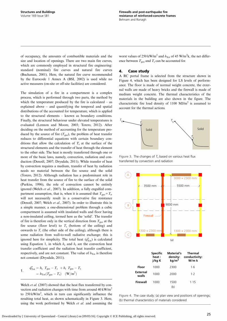
4. Case studyA RC portal frame is selected from the structure shown inFigure 4, which has been designed for LS levels of perform-ance. The floor is made of normal weight concrete, the exter-nal walls are made of heavy bricks and the firewall is made ofmedium weight concrete. The thermal characteristics of thematerials in the building are also shown in the figure. Thecharacteristic fire load density of 1100 MJ/m2 is assumed toaccount for the thermal actions.
TgTs
Solid Solid
Tg
Ts
Figure 3. The changes of Ts based on various heat fluxtransferred by convection and radiation
3500 mm
A
B
C
5500 mm
1300 × 2300 mm
Firewall
1300 × 2300 mm
9000 mm
Floor
Externalwalls
Firewall
1000
1000
1000
2300
2000
1500
(b)
(a)
1·6
1·2
1·15
Specificheat :j/kg K
Material'sdensity:kg/m3
Thermalconductivity:
W/m k
3000 × 2300 mm
Figure 4. The case study: (a) plan view and positions of openings;(b) thermal characteristics of materials considered
25
Structures and BuildingsVolume 169 Issue SB1
Firewalls and post-earthquake fireresistance of reinforced-concrete framesBehnam and Ronagh
Downloaded by [ University of Queensland - Central Library] on [09/05/16]. Copyright © ICE Publishing, all rights reserved.

The structure is designed using ACI 318-08 (ACI, 2008) codefor peak ground acceleration (PGA) of 0·30 g, while a loadcombination of 5·0 kPa and 1·5 kPa for dead load and liveload are considered, respectively. Meanwhile, 100% dead loadand 20% live load are considered in order to find the requiredmass for the calculation of the earthquake load (ASCE, 2013).To define the seismic loads, an equivalent static method rep-resented by Equation 2 is used (IBC, 2003).
2: V ¼ CW
where V, C and W are the shear force at base level, the seismiccoefficient and the total seismic weight of the structure, respec-tively. The seismic coefficient is determined using Equation 3.
3: C ¼ ABI=R
where A correspond to PGA, B is the building response factor,which is dependent on the soil type, I is the importance factorand R is building behaviour factor. For the purpose of thisstudy, a B factor of 2·0, an I factor of 1·0 and an R factor of 7are used; hence the seismic coefficient is 0·0857.
The compressive strength of concrete is assumed to be 24MPaand the yield stress of longitudinal and transverse reinforcingbars is assumed to be 400MPa. Figure 5 shows the geometricproperties of the selected frame. For the thermal analysis,it is assumed that the concrete moisture content is 2%. Thethermal expansion coefficients of rebar and concrete are
assumed as 12�10–6/°C and 10�10–6/°C, respectively. Poissonratio of 0·2 is considered for the concrete. In addition, a350mm cover is assumed for beams and columns. For the fireanalysis, three scenarios are considered: (a) scenario 1 is theleft side exposed to fire; (b) scenario 2 is the right side exposedto fire; and (c) scenario 3 is the entire frame exposed to firewhile no firewall is considered.
The fire curves are determined using the Eurocode 1 Annex Afire curve. Moreover, influences of active measures (on-siteor off-site facilities) are ignored. The analysis is performedfor two situations of before and after earthquake. It isworth noting that when the entire frame is exposed to fire,the exterior side of the external columns is not exposed to fire,whereas all sides of the interior column are subjected tofire. Meanwhile, only three sides of the beams are exposed tofire, because it is assumed that the top of the beams is pro-tected by the concrete slab. When only a part of the frame issubjected to fire, the middle column is exposed to fire onlyfrom one side, where applicable.
5. ResultsUsing the sequential analysis explained in Section 3, the PEFanalysis is performed at the LS level of performance. To dothis, using SAP2000, the frame is monotonically pushedto arrive at 2% drift, that is, 64 mm, corresponding to the LSlevel of performance, although in order to monitor the struc-tural behaviour and in line with FEMA 356 recommendations,the frame is pushed even more than 64mm. The pushover
3200 mm
3500 mm
300
300
8ø20
300
300
8ø20
300
300
4ø204ø20
300
300
8ø20
ø10@125 ø10@125
ø10@
100
ø10@
200
ø10@
100
5500 mm
Figure 5. Geometric properties of the selected frame B
26
Structures and BuildingsVolume 169 Issue SB1
Firewalls and post-earthquake fireresistance of reinforced-concrete framesBehnam and Ronagh
Downloaded by [ University of Queensland - Central Library] on [09/05/16]. Copyright © ICE Publishing, all rights reserved.
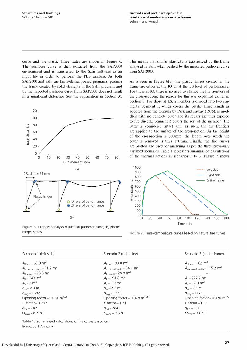
curve and the plastic hinge states are shown in Figure 6.The pushover curve is then extracted from the SAP2000environment and is transferred to the Safir software as aninput file in order to perform the PEF analysis. As bothSAP2000 and Safir are finite-element-based programs, pushingthe frame created by solid elements in the Safir program andby the imported pushover curve from SAP2000 does not resultin a significant difference (see the explanation in Section 3).
This means that similar plasticity is experienced by the frameanalysed in Safir when pushed by the imported pushover curvefrom SAP2000.
As is seen in Figure 6(b), the plastic hinges created in theframe are either at the IO or at the LS level of performance.For those at IO, there is no need to change the fire frontiers ofthe cross-sections; the reason for this was explained earlier inSection 3. For those at LS, a member is divided into two seg-ments. Segment 1, which covers the plastic hinge length asadopted from the formula by Park and Paulay (1975), is mod-elled with no concrete cover and its rebars are thus exposedto fire directly. Segment 2 covers the rest of the member. Thelatter is considered intact and, as such, the fire frontiersare applied to the surface of the cross-section. As the heightof the cross-section is 300 mm, the length over which thecover is removed is thus 150mm. Finally, the fire curvesare plotted and used for analysing as per the three previouslyassumed scenarios. Table 1 represents summarised calculationsof the thermal actions in scenarios 1 to 3. Figure 7 shows
0
20
40
60
80
100
120
0 10 20 30 40 50 60 70 80
Base
she
ar: k
N
Displacement: mm
(a)
(b)
2% drift = 64 mm
Plastic hinges
IO level of performanceLS level of performance
Figure 6. Pushover analysis results: (a) pushover curve; (b) plastichinges states
Scenario 1 (left side) Scenario 2 (right side) Scenario 3 (entire frame)
Afloor=63·0 m2 Afloor=99·0 m2 Afloor=162 m2
Aexternal walls =51·2 m2 Aexternal walls=54·1 m2 Aexternal walls =115·2 m2
Afirewall =28·8 m2 Afirewall =28·8 m2–
At=143 m2 At=191·8 m2 At =277·2 m2
Av=3 m2 Av=9·9 m2 Av=12·9 m2
hw=2·3 m hw=2·3 m hw=2·3 mbavg=1692 bavg=1732 bavg=1775Opening factor=0·031 m1/2 Opening factor=0·078 m1/2 Opening factor=0·070 m1/2
Γ factor=0·297 Γ factor=1·71 Γ factor=1·33qt,d=242 qt,d=284 qt,d=321Θmax=829°C Θmax=897°C Θmax=931°C
Table 1. Summarised calculations of fire curves based onEurocode 1 Annex A
0100200300400500600700800900
1000
0 20 40 60 80 100 120 140 160 180
Tem
pera
ture
: °C
Left side
Right side
Entire frame
Time: min
Figure 7. Time–temperature curves based on natural fire curves
27
Structures and BuildingsVolume 169 Issue SB1
Firewalls and post-earthquake fireresistance of reinforced-concrete framesBehnam and Ronagh
Downloaded by [ University of Queensland - Central Library] on [09/05/16]. Copyright © ICE Publishing, all rights reserved.

the time–temperature curves based the above-mentionedcalculations.
Figure 8 shows the temperature distribution in the beam cross-section based on the applied fire load to the left side. Thefigure shows that exposing the beam to fire during the heatingphase results in a rapid increase in temperature of the surfaceof the cross-section (node 1) and gradual increases inside thecross-section: that is, nodes 2 to 5. During the cooling phase,however, the surface of the concrete loses its temperature at afast pace, while at the rest of the nodes the temperature is stillon the rise. This is due to the low conductivity coefficient ofconcrete, which leads to a slower rate of gaining or losingtemperature during the analysis.
Based on the above-mentioned explanations, the fire analysis isperformed for both situations of before and after earthquake.The analysis terminates when the displacements either globally(i.e. the drift of a certain point) or locally (i.e. the deformationsat the middle of a beam) go beyond the chosen thresholds. Thethresholds have been identified by the curve for displacementsplotted against time step merging towards the vertical asymp-tote by a 1% error.
Fire resistance of the frame is then determined based onvarious failure criteria such as thermal and strength failure cri-teria mentioned in ASTM E119 (ASTM E119-01, ASTM,2001). For instance, an RC member is said to have failed whenthe temperature in the rebar exceeds 593°C or the member isnot able to resist the applied gravity loads (Almand et al.,2004; Kathryn and Buchanan, 2000). There are also otherfailure criteria based on deflection and the rate of deflection.These failure criteria are important because, along withexcessive deflection of the structural members, the structural
integrity cannot be guaranteed. Mostly, the use of deflectionand the rate of deflection criteria help in maintaining thesafety of the building before any collapse occurs. Themaximum allowable deflection varies depending on the definedstructural performance. Often, the deflection for conventionalstructures is limited to L/20 where L is the span length.Additionally, the rate of deflection is limited to L2/9000d(mm/min), where d is the effective depth (Kodur and Dwaikat,2007).
For the undamaged frame, no failures were observed in any ofthe three scenarios during the fire analysis, which explicitlyconfirms the adequate fire resistance of the frame before theearthquake. However, after the pushover analysis, some degreeof damage would exist in the structure. The damaged structureis then loaded with natural fire curves as a sequential load,
–12
–10
–8
–6
–4
–2
00 30 60
∆
90 120
Time: min
Dis
plac
emen
t, ∆
: mm
Figure 9. PEF resistance of frame while left side exposed to fire
Cross-section
0
100
200
300
400
500
600
700
800
0
Tem
pera
ture
: °C
Time: min
Node 1
Node 2
Node 3
Node 4
Node 5
1
2
3
4
5
120906030
Figure 8. Distribution of temperature inside intact beam’scross-section
28
Structures and BuildingsVolume 169 Issue SB1
Firewalls and post-earthquake fireresistance of reinforced-concrete framesBehnam and Ronagh
Downloaded by [ University of Queensland - Central Library] on [09/05/16]. Copyright © ICE Publishing, all rights reserved.
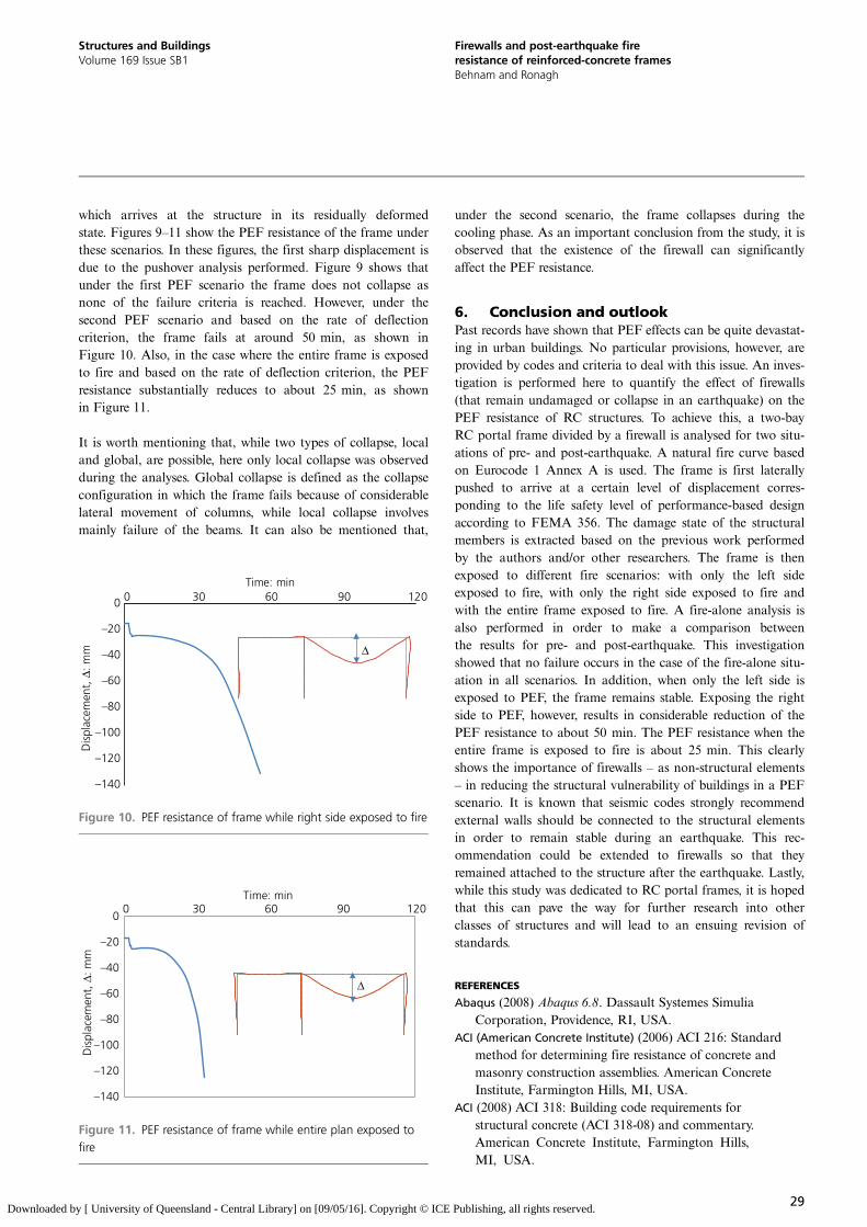
which arrives at the structure in its residually deformedstate. Figures 9–11 show the PEF resistance of the frame underthese scenarios. In these figures, the first sharp displacement isdue to the pushover analysis performed. Figure 9 shows thatunder the first PEF scenario the frame does not collapse asnone of the failure criteria is reached. However, under thesecond PEF scenario and based on the rate of deflectioncriterion, the frame fails at around 50 min, as shown inFigure 10. Also, in the case where the entire frame is exposedto fire and based on the rate of deflection criterion, the PEFresistance substantially reduces to about 25 min, as shownin Figure 11.
It is worth mentioning that, while two types of collapse, localand global, are possible, here only local collapse was observedduring the analyses. Global collapse is defined as the collapseconfiguration in which the frame fails because of considerablelateral movement of columns, while local collapse involvesmainly failure of the beams. It can also be mentioned that,
under the second scenario, the frame collapses during thecooling phase. As an important conclusion from the study, it isobserved that the existence of the firewall can significantlyaffect the PEF resistance.
6. Conclusion and outlookPast records have shown that PEF effects can be quite devastat-ing in urban buildings. No particular provisions, however, areprovided by codes and criteria to deal with this issue. An inves-tigation is performed here to quantify the effect of firewalls(that remain undamaged or collapse in an earthquake) on thePEF resistance of RC structures. To achieve this, a two-bayRC portal frame divided by a firewall is analysed for two situ-ations of pre- and post-earthquake. A natural fire curve basedon Eurocode 1 Annex A is used. The frame is first laterallypushed to arrive at a certain level of displacement corres-ponding to the life safety level of performance-based designaccording to FEMA 356. The damage state of the structuralmembers is extracted based on the previous work performedby the authors and/or other researchers. The frame is thenexposed to different fire scenarios: with only the left sideexposed to fire, with only the right side exposed to fire andwith the entire frame exposed to fire. A fire-alone analysis isalso performed in order to make a comparison betweenthe results for pre- and post-earthquake. This investigationshowed that no failure occurs in the case of the fire-alone situ-ation in all scenarios. In addition, when only the left side isexposed to PEF, the frame remains stable. Exposing the rightside to PEF, however, results in considerable reduction of thePEF resistance to about 50 min. The PEF resistance when theentire frame is exposed to fire is about 25 min. This clearlyshows the importance of firewalls – as non-structural elements– in reducing the structural vulnerability of buildings in a PEFscenario. It is known that seismic codes strongly recommendexternal walls should be connected to the structural elementsin order to remain stable during an earthquake. This rec-ommendation could be extended to firewalls so that theyremained attached to the structure after the earthquake. Lastly,while this study was dedicated to RC portal frames, it is hopedthat this can pave the way for further research into otherclasses of structures and will lead to an ensuing revision ofstandards.
REFERENCES
Abaqus (2008) Abaqus 6.8. Dassault Systemes SimuliaCorporation, Providence, RI, USA.
ACI (American Concrete Institute) (2006) ACI 216: Standardmethod for determining fire resistance of concrete andmasonry construction assemblies. American ConcreteInstitute, Farmington Hills, MI, USA.
ACI (2008) ACI 318: Building code requirements forstructural concrete (ACI 318-08) and commentary.American Concrete Institute, Farmington Hills,MI, USA.
–140
–120
–100
–80
–60
–40
–20
00 30 60 90 120
Dis
plac
emen
t, ∆
: mm
Time: min
∆
Figure 11. PEF resistance of frame while entire plan exposed tofire
–140
–120
–100
–80
–60
–40
–20
0 0 30 60 90 120Time: min
∆
Dis
plac
emen
t, ∆
: mm
Figure 10. PEF resistance of frame while right side exposed to fire
29
Structures and BuildingsVolume 169 Issue SB1
Firewalls and post-earthquake fireresistance of reinforced-concrete framesBehnam and Ronagh
Downloaded by [ University of Queensland - Central Library] on [09/05/16]. Copyright © ICE Publishing, all rights reserved.

Alderighi E and Salvatore W (2009) Structural fire performanceof earthquake-resistant composite steel–concrete frames.Engineering Structures 31(4): 894–909.
Almand K, Phan L, Mcallister T, Starnes M and Gross J (2004)Proceedings of NET-SFPE Workshop for Development ofa National R&D Roadmap for Structural Fire SafetyDesign and Retrofit of Structures, NlSTlR 7133. NationalInstitute of Standards and Technology, Baltimore, MD,USA.
ASCE (2013) SEI/ASCE 7-10: Minimum design loads forbuildings and other structures. American Society of CivilEngineers, Washington DC, USA.
ASTM (2001) ASTM E119-01: Standard methods of fire test ofbuilding construction and materials. ASTM International,West Conshohocken, PA, USA.
Azimi H, Galal K and Pekau OA (2009) Incremental modifiedpushover analysis. The Structural Design of Tall andSpecial Buildings 18(8): 839–859.
Bae S and Bayrak O (2008) Plastic hinge length ofreinforced concrete columns. ACI Structural Journal105(3): 290–300.
Bagchi A (2004). A simplified methd of evaluating the seismicperformance of buildings. Earthquake Engineering andEngineering Vibration 3(2): 223–236.
Bailey CG, Burgess IW and Plank RJ (1996) Analyses of theeffects of cooling and fire spread on steel-framed buildings.Fire Safety Journal 26(4): 273–293.
Bamonte P, Gambarova PG and Meda A (2008)Today’s concretes exposed to fire – test resultsand sectional analysis. Structural Concrete 9(1):19–29.
Behnam B and Ronagh H (2013a) Performance of reinforcedconcrete structures subjected to fire following earthquake.European Journal of Environmental and Civil Engineering17(4): 270–292.
Behnam B and Ronagh HR (2013b) Behavior ofmoment-resisting tall steel structures exposedto a vertically traveling post-earthquake fire. TheStructural Design of Tall and Special Buildings 23(14):1083–1096.
Behnam B and Ronagh HR (2013c) Methodology forinvestigating the behavior of reinforced concretestructures subjected to post earthquake fire. Advances inConcrete Construction, An International Journal 1(1):29–44.
Behnam B and Ronagh HR (2013d) A post-earthquake firefactor to improve the fire resistance of damaged ordinaryreinforced concrete structures. Journal of Structural FireEngineering 4(4): 207–226.
Behnam B and Ronagh HR (2013e) Post-earthquake fireperformance-based behavior of reinforced concretestructures. Earthquakes and Structures, An InternationalJournal 5(4): 379–394.
Behnam B and Ronagh HR (2013f) Post-earthquake fireresistance of CFRP strengthened reinforced concrete
structures. The Structural Design of Tall and SpecialBuildings 23(11): 814–832.
Behnam B, Ronagh HR and Lim PJ (2014) Analytical evaluationof post-earthquake fire resistance of CFRP laminatedreinforced concrete joints based on experimentalobservations. European Journal of Environmental and CivilEngineering, in press.
Behnam B and Ronagh H (2015) Post-earthquake fireperformance-based behaviour of unprotected momentresisting 2D steel frames. KSCE Journal of CivilEngineering 19(1): 274–284.
Behnam B and Ronagh HR (2014a) An engineering solution toimprove post-earthquake fire resistance in importantreinforced concrete structures. Advances in StructuralEngineering 17(7): 993–1009.
Behnam B and Ronagh HR (2014b) A study on the effectof sequential post-earthquake fire on the performance ofreinforced concrete structures. International Journal ofStructural Integrity 5(2): 141–166.
Behnam B, Ronagh HR and Lim PJ (2015) Numerical evaluationof the post-earthquake fire resistance of CFRP-strengthened reinforced concrete joints based onexperimental observations. European Journal ofEnvironmental and Civil Engineering, DOI: 10.1080/19648189.2015.1018448.
BIS (Bureau of Indian Standards) (2005) National building codeof India. BIS, New Delhi, India.
Borden F (1996) The 1994 Northridge earthquake and the firesthat followed. In Proceedings of 13th Meeting of the UJNRPanel on Fire Research and Safety (Kellie A (ed.)).National Institute of Standards and Technology,California, USA, pp. 303–312.
Braxtan NL and Pessiki SP (2011) Post earthquake fireperformance of sprayed fire-resistive material on steelmoment frames. Journal of Structural Engineering – ASCE137(9): 946–953.
BSI (2002) Eurocode 0: Basis of structural design. NationalStandards Authority of Ireland, Dublin, UK.
Buchanan A (2001) Structural Design for Fire Safety.John Wiley and Sons, New York, NY, USA.
Calvi G, Pinho R, Magenes G et al. (2006) Development ofseismic vulnerability assessment methodologies over thepast 30 years. ISET Journal of Earthquake Technology43(3): 75–104.
Chen S, Lee GC and Shinozuka M (2004) Hazardmitigation for earthquake and subsequent fire.Proceedings of Annual Meeting: Networking ofYoung Earthquake Engineering Researchers andProfessionals, Honolulu, Hawaii. MultidisciplinaryCentre for Earthquake Engineering Research, Buffalo,NY, USA.
Chopra AK and Goel RK (2004) A modal pushover analysisprocedure to estimate seismic demands for unsymmetric-plan buildings. Earthquake Engineering and StructuralDynamics 33(8): 903–927.
30
Structures and BuildingsVolume 169 Issue SB1
Firewalls and post-earthquake fireresistance of reinforced-concrete framesBehnam and Ronagh
Downloaded by [ University of Queensland - Central Library] on [09/05/16]. Copyright © ICE Publishing, all rights reserved.

Collier P (2005) Post earthquake performance of passivefire protection systems. Building Research Levy andthe Department of Building and Housing, Sydney,Australia.
Debicki G, Haniche R and Delhomme F (2012) An experimentalmethod for assessing the spalling sensitivity of concretemixture submitted to high temperature. Cement andConcrete Composites 34(8): 958–963.
Della Corte G, Landolfo R and Mazzolani FM (2003) Postearthquake fire resistance of moment resisting steel frames.Fire Safety Journal 38(7): 593–612.
Denoël JF (2007) Fire Safety and Concrete Structures.Federation of Belgian Cement Industry, Brussels,Belgium.
Drysdale D (2011) An Introduction to Fire Dynamics, 3rd edn.John Wiley and Sons, Chichester, UK.
Ervine A, Gillie M, Stratford TJ and Pankaj P (2011) Thermaldiffusivity of tensile cracked concrete. Proceedings of theInternational Conference on Applications of Structural FireEngineering, Prague, Czech Republic.
Ervine A, Gillie M, Stratford TJ and Pankaj P (2012) Thermalpropagation through tensile cracks in reinforced concrete.Journal of Materials in Civil Engineering 24(5): 516–522.
Faggiano B and Gregorgio D (2010) Assessment of therobustness of structures subjected to fire followingearthquake through a performance-based approach. InUrban Habitat Constructions under Catastrophic Events(Mazzolani FM (ed.)). Taylor and Francis Group,London, UK.
Faggiano B and Mazzolani FM (2011) Fire after earthquakerobustness evaluation and design: Application to steelstructures. Steel Construction 4(3): 183–187.
Fajfar P (2000) A nonlinear analysis method forperformance based seismic design. Earthquake Spectra16(3): 573–592.
FEMA (Federal Emergency Management Agency) (2000)FEMA356: Prestandard and commentary for the seismicrehabilitation of buildings rehabilitation requirements.American Society of Civil Engineers, Washington, DC,USA.
Franssen JM (2005) SAFIR: A thermal/structural program formodeling structures under fire. Engineering Journal 42(3):143–150.
Franssen JM, Kodur V and Zaharia R (eds) (2009) Introduction.In Designing Steel Structures for Fire Safety. CRC Press,Boca Raton, FL, USA.
Ghoreishi MBA and Sutlan MA (2009) Estimating the responseof structural systems to fire exposure: state-of-the-artreview. Proceedings of Fire and Materials 11th InternationalConference, San Francisco, CA, USA. National ResearchCouncil Canada, pp. 475–483.
Godat A (2008) Finite Element Modelling of ExternallyShear-Strengthened Beams Using Fibre ReinforcedPolymers. PhD thesis NR42676, Universite de Sherbrooke,Canada.
Han SW and Chopra AK (2006) Approximate incrementaldynamic analysis using the modal pushover analysisprocedure. Earthquake Engineering and StructuralDynamics 35(15): 1853–1873.
Hanus F (2010) Analysis of Simple Connections in SteelStructures Subjected to Natural Fires. PhD thesis,University of Liège, Belgium.
Hertz KD (2003) Limits of spalling of fire-exposed concrete.Fire Safety Journal 38(2): 103–116.
Hertz KD and Sørensen LS (2005) Test method for spalling offire exposed concrete. Fire Safety Journal 40(5): 466–476.
Kabeyasawa T and Mostafaei H (2007) Axial-shear–flexureinteraction approach for reinforced concrete columns. ACIStructural Journal 104(2): 218–226.
Kalkan E and Chopra AK (2011) Modal-pushover-based ground-motion scaling procedure (author abstract). Journal ofStructural Engineering 137(3): 298.
Karlsson B and Quintiere JG (eds) (1999) Energy release rates.In Enclosure Fire Dynamics. CRC Press, Boca Raton, FL,USA.
Kathryn L and Buchanan A (2000) Fire Design of SteelMembers. The University of Canterbury, New Zealand,Fire Engineering Research Report.
Kodur VKR (2005) Guidelines for fire resistance design ofhigh-strength concrete columns. Journal of Fire ProtectionEngineering 15(2): 93–106.
Kodur V and Dwaikat M (2007) Performance-based fire safetydesign of reinforced concrete beams. Journal of FireProtection Engineering 17(4): 293–320.
Kodur VKR, Garlock M and Iwankiw N (2012) Structures in fire:state-of-the-art, research and training needs. FireTechnology 48(4): 825–839.
Kodur VKR, Wang TC and Cheng FP (2004) Predictingthe fire resistance behaviour of high strengthconcrete columns. Cement and Concrete Composites 26(2):141–153.
Krawinkler H and Seneviratna GDPK (1998) Pros and cons of apushover analysis of seismic performance evaluation.Engineering Structures 20(4): 452–464.
Kwak HG and Kim SP (2002) Nonlinear analysis of RC beamsbased on moment–curvature relation. Computers andStructures 80(7): 615–628.
Kwasniewski A (2011) Analyses of Structures Under Fire.Warsaw University of Technology, Warsaw, Poland.
Lee GC, Chen S, Li G and Tong M (2004) On performance basedanalysis of buildings for multi-hazard mitigation. SteelStructures 4(4): 231–238.
Lee TH and Mosalam KM (2004) Probabilistic fiber elementmodeling of reinforced concrete structures. Computers andStructures 82(27): 2285–2299.
Lennon T and Moore D (2003) The natural fire safety concept –full-scale tests at Cardington. Fire Safety Journal 38(7):623–643.
Lin H, Clifford MJ, Long AC and Sherburn M (2009) Finiteelement modelling of fabric shear. Modelling and
31
Structures and BuildingsVolume 169 Issue SB1
Firewalls and post-earthquake fireresistance of reinforced-concrete framesBehnam and Ronagh
Downloaded by [ University of Queensland - Central Library] on [09/05/16]. Copyright © ICE Publishing, all rights reserved.

Simulation in Materials Science and Engineering 17(1):015008.
Majorana CE, Salomoni VA, Mazzucco G and Khoury GA (2010)An approach for modelling concrete spalling in finitestrains. Mathematics and Computers in Simulation 80(8):1694–1712.
Meacham BJ and Custer RLP (2002) Performance-basedfire safety engineering: an introduction of basicconcepts. Journal of Fire Protection Engineering 7(2):35–53.
Meada M and Kang D (2009) Post-earthquake damageevaluation of RC buildings. Journal of Advanced ConcreteTechnology 7(3): 327–335.
Mohammadi J and Alysian S (1992) Analysis of post-earthquakefire hazard. Proceedings of Earthquake Engineering,10th World Conference, Madrid, Spain, See http://www.iitk.ac.in/nicee/wcee/tenth_conf_spain/ (accessed24/06/2015).
Mostafaei H and Kabeyasawa T (2010) Performance of asix-story reinforced concrete structure in post-earthquakefire. Proceedings of 10th Canadian Conference onEarthquake Engineering. Institute for Research inConstruction, Toronto, Ontario.
Mousavi S, Kodur VKR and Bagchi A (2008) Review of postearthquake fire hazard to building structures. CanadianJournal of Civil Engineering 35(7): 689–698.
Mwafy AM and Elnashai AS (2001) Static pushover versusdynamic collapse analysis of RC buildings. EngineeringStructures 23(5): 407–424.
Nakano Y, Maeda M, Kuramoto H and Murakami M (2004)Guidelines for post-earthquake damage eveluation andrehabilitation of RC buildings in Japan. Proceedings of13th World Conference on Earthquake Engineering,Vancouver, Canada.
Nasirzadeh G, Peyghaleh E and Zolfaghari MR (2009) Firefollowing earthquake, intra-structure ignition modeling.Journal of Fire Sciences 27(1): 45–79.
Park R and Paulay T (1975) Reinforced Concrete Structures.John Wiley and Sons, New York, NY, USA.
Pucinotti R, Bursi OS and Demonceau JF (2011)Post-earthquake fire and seismic performance ofwelded steel–concrete composite beam-to-columnjoints. Journal of Constructional Steel Research 67(9):1358–1375.
Purkiss JA (1996) Fire Safety Engineering: Design of Structures.Elsevier, Burlington, MA, USA.
Robertson J and Mehaffey J (2000) Accounting for firefollowing earthquake in the development of performancebased building codes. Proceedings of the 12th WorldConference on Earthquake Engineering. New ZealandSociety for Earthquake Engineering, Auckland, NewZealand.
Roh H, Reinhorn AM and Lee JS (2012) Power spread plasticitymodel for inelastic analysis of reinforced concretestructures. Engineering Structures 39(2): 148–161.
Ronagh HR and Behnam B (2012) Investigating theeffect of prior damage on the post-earthquake fireresistance of reinforced concrete portal frames.International Journal of Concrete Structures and Materials6(4): 209–220.
Ryder NL, Wolin SD and Milke JA (2002) An investigation of thereduction in fire resistance of steel columns caused by lossof spray-applied fire protection. Journal of fire protectionengineering 12(1): 31–44.
SAP2000 (2002) SAP2000-V14: Integrated Finite ElementAnalysis and Design of Structures Basic Analysis ReferenceManual. Computers and Structures, Inc., Berkeley, CA,USA.
Scawthorn CR (2008) Fire Following Earthquake. The ShakeOut Scenario. USGS – Science for Changing World,Washington, DC, USA.
Scawthorn C, Eidinger JM and Schiff A (2005) Fire FollowingEarthquake. American Society of Civil Engineers, Reston,VA, USA.
Sharma UK, Bhargava P, Singh BB et al. (2012) Full-scale testingof a damaged reinforced concrete frame in fire. Proceedingsof the Institution of Civil Engineers – Structures andBuildings 165(7): 335–346, http://dx.doi.org/10.1680/stbu.11.00031.
Smith FP (1991) Concrete spalling – controlled fire testsand review. Journal – Forensic Science Society 31: 67–75.
Taylor J (2003) Post Earthquake Fire in Tall Buildings and theNew Zealand Building Code. MSc thesis, University ofCanterbury, New Zealand.
Tomecek D and Milke J (1993) A study of the effect of partialloss of protection on the fire resistance of steel columns.Fire Technology 29(1): 3–21.
Torero JL (2012) Assessing the true performance ofstructures in fire. In Performance-based and Life-cycleStructural Engineering. University of Hong Kong,Hong Kong.
Wang WY and Li GQ (2009) Fire-resistance study of restrainedsteel columns with partial damage to fire protection. FireSafety Journal 44: 1088–1094.
Welch S, Jowsey A, Deeny S, Morgan R and Torero JL (2007)BRE large compartment fire tests – Characterisingpost-flashover fires for model validation. Fire SafetyJournal 42: 548–567.
Wellington Lifelines Group (2002) Fire Following Earthquake:Identifying Key Issues for New Zealand. Fire ServiceCommission, New Zealand.
Xie Y and Ren AZ (2004) The simulation of post-earthquakefire-prone area based on GIS. Journal of Fire Sciences22(5): 421–439.
Youssef MA and Moftah M (2007) General stress–strainrelationship for concrete at elevated temperatures.Engineering Structures 29(10): 2618–2634.
Zaharia R and Pintea D (2009) Fire after earthquake analysis ofsteel moment resisting frames. International Journal ofSteel Structures 9(4): 275–284.
32
Structures and BuildingsVolume 169 Issue SB1
Firewalls and post-earthquake fireresistance of reinforced-concrete framesBehnam and Ronagh
Downloaded by [ University of Queensland - Central Library] on [09/05/16]. Copyright © ICE Publishing, all rights reserved.

Zhao J and Sritharan S (2007) Modeling of strain penetrationeffects in fiber-based analysis of reinforced concretestructures. ACI Structural Journal 104(2): 133–141.
Zolfaghari MR, Peyghaleh E and Nasirzadeh G (2009) Firefollowing earthquake, intra-structure ignition modeling.Journal of Fire Sciences 27(1): 45–79.
WHAT DO YOU THINK?
To discuss this paper, please email up to 500 words to theeditor at [email protected]. Your contribution will beforwarded to the author(s) for a reply and, if consideredappropriate by the editorial panel, will be published asdiscussion in a future issue of the journal.
Proceedings journals rely entirely on contributions sent inby civil engineering professionals, academics and stu-dents. Papers should be 2000–5000 words long (briefingpapers should be 1000–2000 words long), with adequateillustrations and references. You can submit your paperonline via www.icevirtuallibrary.com/content/journals,where you will also find detailed author guidelines.
33
Structures and BuildingsVolume 169 Issue SB1
Firewalls and post-earthquake fireresistance of reinforced-concrete framesBehnam and Ronagh
Downloaded by [ University of Queensland - Central Library] on [09/05/16]. Copyright © ICE Publishing, all rights reserved.