
Fired Heaters for General Refinery Service
208
Fired Heaters for General Refinery Service API STANDARD 560 THIRD EDITION, MAY 2001 COPYRIGHT American Petroleum Institute Licensed by Information Handling Services COPYRIGHT American Petroleum Institute Licensed by Information Handling Services
Transcript of Fired Heaters for General Refinery Service
Fired Heaters for General Refinery Service
API STANDARD 560THIRD EDITION, MAY 2001
COPYRIGHT American Petroleum InstituteLicensed by Information Handling ServicesCOPYRIGHT American Petroleum InstituteLicensed by Information Handling Services

COPYRIGHT American Petroleum InstituteLicensed by Information Handling ServicesCOPYRIGHT American Petroleum InstituteLicensed by Information Handling Services
Fired Heaters for GeneralRefinery Service
Downstream Segment
API STANDARD 560THIRD EDITION, MAY 2001
COPYRIGHT American Petroleum InstituteLicensed by Information Handling ServicesCOPYRIGHT American Petroleum InstituteLicensed by Information Handling Services

SPECIAL NOTES
API publications necessarily address problems of a general nature. With respect to partic-ular circumstances, local, state, and federal laws and regulations should be reviewed.
API is not undertaking to meet the duties of employers, manufacturers, or suppliers towarn and properly train and equip their employees, and others exposed, concerning healthand safety risks and precautions, nor undertaking their obligations under local, state, or fed-eral laws.
Information concerning safety and health risks and proper precautions with respect to par-ticular materials and conditions should be obtained from the employer, the manufacturer orsupplier of that material, or the material safety data sheet.
Nothing contained in any API publication is to be construed as granting any right, byimplication or otherwise, for the manufacture, sale, or use of any method, apparatus, or prod-uct covered by letters patent. Neither should anything contained in the publication be con-strued as insuring anyone against liability for infringement of letters patent.
Generally, API standards are reviewed and revised, reaffirmed, or withdrawn at least everyfive years. Sometimes a one-time extension of up to two years will be added to this reviewcycle. This publication will no longer be in effect five years after its publication date as anoperative API standard or, where an extension has been granted, upon republication. Statusof the publication can be ascertained from the API Downstream Segment [telephone (202)682-8000]. A catalog of API publications and materials is published annually and updatedquarterly by API, 1220 L Street, N.W., Washington, D.C. 20005.
This document was produced under API standardization procedures that ensure appropri-ate notification and participation in the developmental process and is designated as an APIstandard. Questions concerning the interpretation of the content of this standard or com-ments and questions concerning the procedures under which this standard was developedshould be directed in writing to the standardization manager, American Petroleum Institute,1220 L Street, N.W., Washington, D.C. 20005. Requests for permission to reproduce ortranslate all or any part of the material published herein should also be addressed to the gen-eral manager.
API standards are published to facilitate the broad availability of proven, sound engineer-ing and operating practices. These standards are not intended to obviate the need for apply-ing sound engineering judgment regarding when and where these standards should beutilized. The formulation and publication of API standards is not intended in any way toinhibit anyone from using any other practices.
Any manufacturer marking equipment or materials in conformance with the markingrequirements of an API standard is solely responsible for complying with all the applicablerequirements of that standard. API does not represent, warrant, or guarantee that such prod-ucts do in fact conform to the applicable API standard.
All rights reserved. No part of this work may be reproduced, stored in a retrieval system, or transmitted by any means, electronic, mechanical, photocopying, recording, or otherwise,
without prior written permission from the publisher. Contact the Publisher, API Publishing Services, 1220 L Street, N.W., Washington, D.C. 20005.
Copyright © 2001 American Petroleum Institute
COPYRIGHT American Petroleum InstituteLicensed by Information Handling ServicesCOPYRIGHT American Petroleum InstituteLicensed by Information Handling Services
FOREWORD
API publications may be used by anyone desiring to do so. Every effort has been made bythe Institute to assure the accuracy and reliability of the data contained in them; however, theInstitute makes no representation, warranty, or guarantee in connection with this publicationand hereby expressly disclaims any liability or responsibility for loss or damage resultingfrom its use or for the violation of any federal, state, or municipal regulation with which thispublication may conflict.
Suggested revisions are invited and should be submitted to the standardization manager,American Petroleum Institute, 1220 L Street, N.W., Washington, D.C. 20005.
iii
COPYRIGHT American Petroleum InstituteLicensed by Information Handling ServicesCOPYRIGHT American Petroleum InstituteLicensed by Information Handling Services

COPYRIGHT American Petroleum InstituteLicensed by Information Handling ServicesCOPYRIGHT American Petroleum InstituteLicensed by Information Handling Services

CONTENTS
Page
1 GENERAL. . . . . . . . . . . . . . . . . . . . . . . . . . . . . . . . . . . . . . . . . . . . . . . . . . . . . . . . . . . . 11.1 Scope. . . . . . . . . . . . . . . . . . . . . . . . . . . . . . . . . . . . . . . . . . . . . . . . . . . . . . . . . . . 11.2 Alternative Designs. . . . . . . . . . . . . . . . . . . . . . . . . . . . . . . . . . . . . . . . . . . . . . . . 11.3 Conflicting Requirements . . . . . . . . . . . . . . . . . . . . . . . . . . . . . . . . . . . . . . . . . . . 11.4 Definition of Terms. . . . . . . . . . . . . . . . . . . . . . . . . . . . . . . . . . . . . . . . . . . . . . . . 11.5 Nomenclature . . . . . . . . . . . . . . . . . . . . . . . . . . . . . . . . . . . . . . . . . . . . . . . . . . . . 41.6 Normative Codes and Standards. . . . . . . . . . . . . . . . . . . . . . . . . . . . . . . . . . . . . . 41.7 Informative Codes and Standards. . . . . . . . . . . . . . . . . . . . . . . . . . . . . . . . . . . . . 81.8 Proposals . . . . . . . . . . . . . . . . . . . . . . . . . . . . . . . . . . . . . . . . . . . . . . . . . . . . . . . . 91.9 Documentation . . . . . . . . . . . . . . . . . . . . . . . . . . . . . . . . . . . . . . . . . . . . . . . . . . . 9
2 DESIGN CONSIDERATIONS . . . . . . . . . . . . . . . . . . . . . . . . . . . . . . . . . . . . . . . . . . 102.1 Process. . . . . . . . . . . . . . . . . . . . . . . . . . . . . . . . . . . . . . . . . . . . . . . . . . . . . . . . . 102.2 Combustion . . . . . . . . . . . . . . . . . . . . . . . . . . . . . . . . . . . . . . . . . . . . . . . . . . . . . 112.3 Mechanical . . . . . . . . . . . . . . . . . . . . . . . . . . . . . . . . . . . . . . . . . . . . . . . . . . . . . 11
3 TUBES. . . . . . . . . . . . . . . . . . . . . . . . . . . . . . . . . . . . . . . . . . . . . . . . . . . . . . . . . . . . . . 113.1 General . . . . . . . . . . . . . . . . . . . . . . . . . . . . . . . . . . . . . . . . . . . . . . . . . . . . . . . . 113.2 Extended Surface . . . . . . . . . . . . . . . . . . . . . . . . . . . . . . . . . . . . . . . . . . . . . . . . 133.3 Materials . . . . . . . . . . . . . . . . . . . . . . . . . . . . . . . . . . . . . . . . . . . . . . . . . . . . . . . 13
4 HEADERS . . . . . . . . . . . . . . . . . . . . . . . . . . . . . . . . . . . . . . . . . . . . . . . . . . . . . . . . . . . 134.1 General . . . . . . . . . . . . . . . . . . . . . . . . . . . . . . . . . . . . . . . . . . . . . . . . . . . . . . . . 134.2 Plug Headers . . . . . . . . . . . . . . . . . . . . . . . . . . . . . . . . . . . . . . . . . . . . . . . . . . . . 134.3 Return Bends. . . . . . . . . . . . . . . . . . . . . . . . . . . . . . . . . . . . . . . . . . . . . . . . . . . . 144.4 Materials . . . . . . . . . . . . . . . . . . . . . . . . . . . . . . . . . . . . . . . . . . . . . . . . . . . . . . . 15
5 PIPING, TERMINALS, AND MANIFOLDS . . . . . . . . . . . . . . . . . . . . . . . . . . . . . . . 155.1 General . . . . . . . . . . . . . . . . . . . . . . . . . . . . . . . . . . . . . . . . . . . . . . . . . . . . . . . . 155.2 Allowable Movement and Loads . . . . . . . . . . . . . . . . . . . . . . . . . . . . . . . . . . . . 165.3 Materials . . . . . . . . . . . . . . . . . . . . . . . . . . . . . . . . . . . . . . . . . . . . . . . . . . . . . . . 16
6 TUBE SUPPORTS . . . . . . . . . . . . . . . . . . . . . . . . . . . . . . . . . . . . . . . . . . . . . . . . . . . . 166.1 General . . . . . . . . . . . . . . . . . . . . . . . . . . . . . . . . . . . . . . . . . . . . . . . . . . . . . . . . 166.2 Loads and Allowable Stress . . . . . . . . . . . . . . . . . . . . . . . . . . . . . . . . . . . . . . . . 176.3 Materials . . . . . . . . . . . . . . . . . . . . . . . . . . . . . . . . . . . . . . . . . . . . . . . . . . . . . . . 17
7 REFRACTORIES AND INSULATION . . . . . . . . . . . . . . . . . . . . . . . . . . . . . . . . . . . 187.1 General . . . . . . . . . . . . . . . . . . . . . . . . . . . . . . . . . . . . . . . . . . . . . . . . . . . . . . . . 187.2 Brick and Tile Construction . . . . . . . . . . . . . . . . . . . . . . . . . . . . . . . . . . . . . . . . 187.3 Castable Construction. . . . . . . . . . . . . . . . . . . . . . . . . . . . . . . . . . . . . . . . . . . . . 197.4 Ceramic Fiber Construction . . . . . . . . . . . . . . . . . . . . . . . . . . . . . . . . . . . . . . . . 207.5 Multicomponent Lining Construction . . . . . . . . . . . . . . . . . . . . . . . . . . . . . . . . 217.6 Materials . . . . . . . . . . . . . . . . . . . . . . . . . . . . . . . . . . . . . . . . . . . . . . . . . . . . . . . 21
8 STRUCTURES AND APPURTENANCES . . . . . . . . . . . . . . . . . . . . . . . . . . . . . . . . 218.1 General . . . . . . . . . . . . . . . . . . . . . . . . . . . . . . . . . . . . . . . . . . . . . . . . . . . . . . . . 218.2 Structures . . . . . . . . . . . . . . . . . . . . . . . . . . . . . . . . . . . . . . . . . . . . . . . . . . . . . . 228.3 Header Boxes, Doors, and Ports. . . . . . . . . . . . . . . . . . . . . . . . . . . . . . . . . . . . . 228.4 Ladders, Platforms, and Stairways . . . . . . . . . . . . . . . . . . . . . . . . . . . . . . . . . . . 228.5 Materials . . . . . . . . . . . . . . . . . . . . . . . . . . . . . . . . . . . . . . . . . . . . . . . . . . . . . . . 23
9 STACKS, DUCTS, AND BREECHING . . . . . . . . . . . . . . . . . . . . . . . . . . . . . . . . . . . 239.1 General . . . . . . . . . . . . . . . . . . . . . . . . . . . . . . . . . . . . . . . . . . . . . . . . . . . . . . . . 239.2 Design Considerations . . . . . . . . . . . . . . . . . . . . . . . . . . . . . . . . . . . . . . . . . . . . 24
v
COPYRIGHT American Petroleum InstituteLicensed by Information Handling ServicesCOPYRIGHT American Petroleum InstituteLicensed by Information Handling Services

Page
9.3 Allowable Stresses . . . . . . . . . . . . . . . . . . . . . . . . . . . . . . . . . . . . . . . . . . . . . . . 249.4 Static Design . . . . . . . . . . . . . . . . . . . . . . . . . . . . . . . . . . . . . . . . . . . . . . . . . . . . 259.5 Wind-Induced Vibration Design. . . . . . . . . . . . . . . . . . . . . . . . . . . . . . . . . . . . . 269.6 Materials . . . . . . . . . . . . . . . . . . . . . . . . . . . . . . . . . . . . . . . . . . . . . . . . . . . . . . . 279.7 Alternate Design Methods . . . . . . . . . . . . . . . . . . . . . . . . . . . . . . . . . . . . . . . . . 27
10 BURNERS, SOOTBLOWERS, AND DAMPER CONTROLS . . . . . . . . . . . . . . . . . 2710.1 Burners . . . . . . . . . . . . . . . . . . . . . . . . . . . . . . . . . . . . . . . . . . . . . . . . . . . . . . . . 2710.2 Sootblowers. . . . . . . . . . . . . . . . . . . . . . . . . . . . . . . . . . . . . . . . . . . . . . . . . . . . . 3010.3 Damper Controls. . . . . . . . . . . . . . . . . . . . . . . . . . . . . . . . . . . . . . . . . . . . . . . . . 30
11 CENTRIFUGAL FANS AND DRIVERS FOR FIRED HEATER SYSTEMS . . . . . 3011.1 General . . . . . . . . . . . . . . . . . . . . . . . . . . . . . . . . . . . . . . . . . . . . . . . . . . . . . . . . 3011.2 Definition of Terms. . . . . . . . . . . . . . . . . . . . . . . . . . . . . . . . . . . . . . . . . . . . . . . 3111.3 Fan Design Considerations. . . . . . . . . . . . . . . . . . . . . . . . . . . . . . . . . . . . . . . . . 3211.4 Fan Housings . . . . . . . . . . . . . . . . . . . . . . . . . . . . . . . . . . . . . . . . . . . . . . . . . . . 3211.5 Fan Housing Connections. . . . . . . . . . . . . . . . . . . . . . . . . . . . . . . . . . . . . . . . . . 3311.6 External Forces and Moments . . . . . . . . . . . . . . . . . . . . . . . . . . . . . . . . . . . . . . 3311.7 Rotating Elements. . . . . . . . . . . . . . . . . . . . . . . . . . . . . . . . . . . . . . . . . . . . . . . . 3311.8 Shaft Sealing of Fans . . . . . . . . . . . . . . . . . . . . . . . . . . . . . . . . . . . . . . . . . . . . . 3411.9 Critical Speeds/Resonance . . . . . . . . . . . . . . . . . . . . . . . . . . . . . . . . . . . . . . . . . 3411.10 Vibration and Balancing . . . . . . . . . . . . . . . . . . . . . . . . . . . . . . . . . . . . . . . . . . . 3411.11 Bearings and Bearing Housings . . . . . . . . . . . . . . . . . . . . . . . . . . . . . . . . . . . . . 3411.12 Lubrication . . . . . . . . . . . . . . . . . . . . . . . . . . . . . . . . . . . . . . . . . . . . . . . . . . . . . 3511.13 Materials . . . . . . . . . . . . . . . . . . . . . . . . . . . . . . . . . . . . . . . . . . . . . . . . . . . . . . . 3511.14 Welding . . . . . . . . . . . . . . . . . . . . . . . . . . . . . . . . . . . . . . . . . . . . . . . . . . . . . . . . 3511.15 Nameplates and Rotation Arrows. . . . . . . . . . . . . . . . . . . . . . . . . . . . . . . . . . . . 3511.16 Drivers and Accessories . . . . . . . . . . . . . . . . . . . . . . . . . . . . . . . . . . . . . . . . . . . 3611.17 Couplings and Guards. . . . . . . . . . . . . . . . . . . . . . . . . . . . . . . . . . . . . . . . . . . . . 3611.18 Controls and Instrumentation . . . . . . . . . . . . . . . . . . . . . . . . . . . . . . . . . . . . . . . 3611.19 Dampers or Variable Inlet Vanes. . . . . . . . . . . . . . . . . . . . . . . . . . . . . . . . . . . . . 3711.20 Piping and Appurtenances . . . . . . . . . . . . . . . . . . . . . . . . . . . . . . . . . . . . . . . . . 3711.21 Coatings, Insulation, and Jacketing . . . . . . . . . . . . . . . . . . . . . . . . . . . . . . . . . . 3811.22 Inspection and Testing . . . . . . . . . . . . . . . . . . . . . . . . . . . . . . . . . . . . . . . . . . . . 3811.23 Preparation for Shipment . . . . . . . . . . . . . . . . . . . . . . . . . . . . . . . . . . . . . . . . . . 3911.24 Vendor Data . . . . . . . . . . . . . . . . . . . . . . . . . . . . . . . . . . . . . . . . . . . . . . . . . . . . 40
12 INSTRUMENT AND AUXILIARY CONNECTIONS . . . . . . . . . . . . . . . . . . . . . . . 4012.1 Flue Gas and Air . . . . . . . . . . . . . . . . . . . . . . . . . . . . . . . . . . . . . . . . . . . . . . . . . 4012.2 Process Fluid Temperature . . . . . . . . . . . . . . . . . . . . . . . . . . . . . . . . . . . . . . . . . 4112.3 Auxiliary Connections . . . . . . . . . . . . . . . . . . . . . . . . . . . . . . . . . . . . . . . . . . . . 4112.4 Tube-Skin Thermocouples . . . . . . . . . . . . . . . . . . . . . . . . . . . . . . . . . . . . . . . . . 42
13 SHOP FABRICATION AND FIELD ERECTION . . . . . . . . . . . . . . . . . . . . . . . . . . . 4213.1 General . . . . . . . . . . . . . . . . . . . . . . . . . . . . . . . . . . . . . . . . . . . . . . . . . . . . . . . . 4213.2 Steel Fabrication . . . . . . . . . . . . . . . . . . . . . . . . . . . . . . . . . . . . . . . . . . . . . . . . . 4213.3 Coil Fabrication . . . . . . . . . . . . . . . . . . . . . . . . . . . . . . . . . . . . . . . . . . . . . . . . . 4313.4 Painting and Galvanizing . . . . . . . . . . . . . . . . . . . . . . . . . . . . . . . . . . . . . . . . . . 4313.5 Refractories and Insulation. . . . . . . . . . . . . . . . . . . . . . . . . . . . . . . . . . . . . . . . . 4413.6 Preparation For Shipment . . . . . . . . . . . . . . . . . . . . . . . . . . . . . . . . . . . . . . . . . . 4413.7 Field Erection . . . . . . . . . . . . . . . . . . . . . . . . . . . . . . . . . . . . . . . . . . . . . . . . . . . 45
14 INSPECTION, EXAMINATION, AND TESTING . . . . . . . . . . . . . . . . . . . . . . . . . . 4514.1 General . . . . . . . . . . . . . . . . . . . . . . . . . . . . . . . . . . . . . . . . . . . . . . . . . . . . . . . . 4514.2 Weld Inspection and Examination . . . . . . . . . . . . . . . . . . . . . . . . . . . . . . . . . . . 4514.3 Castings Examination . . . . . . . . . . . . . . . . . . . . . . . . . . . . . . . . . . . . . . . . . . . . . 46
vi
COPYRIGHT American Petroleum InstituteLicensed by Information Handling ServicesCOPYRIGHT American Petroleum InstituteLicensed by Information Handling Services

Page
14.4 Examination of Other Components . . . . . . . . . . . . . . . . . . . . . . . . . . . . . . . . . . 4714.5 Testing . . . . . . . . . . . . . . . . . . . . . . . . . . . . . . . . . . . . . . . . . . . . . . . . . . . . . . . . . 47
APPENDIX A EQUIPMENT DATA SHEETS. . . . . . . . . . . . . . . . . . . . . . . . . . . . . . . . 49APPENDIX B PURCHASER’S CHECKLIST . . . . . . . . . . . . . . . . . . . . . . . . . . . . . . . . 79APPENDIX C PROPOSED SHOP ASSEMBLY CONDITIONS . . . . . . . . . . . . . . . . . 85APPENDIX D STRESS CURVES FOR USE IN THE DESIGN OF TUBE
SUPPORT ELEMENTS. . . . . . . . . . . . . . . . . . . . . . . . . . . . . . . . . . . . . . 89APPENDIX E AIR PREHEAT SYSTEMS FOR FIRED PROCESS HEATERS. . . . 105APPENDIX E.A FLUE GAS DEW POINT DISCUSSION AND BIBLIOGRAPHY . . 139APPENDIX F MEASUREMENT OF THE EFFICIENCY OF FIRED PROCESS
HEATERS. . . . . . . . . . . . . . . . . . . . . . . . . . . . . . . . . . . . . . . . . . . . . . . . 143APPENDIX F.A MODEL FORMAT FOR DATA SHEETS. . . . . . . . . . . . . . . . . . . . . . 153APPENDIX F.B MODEL FORMAT FOR WORK SHEETS . . . . . . . . . . . . . . . . . . . . . 161APPENDIX F.C SAMPLE WORK SHEETS FOR AN OIL-FIRED HEATER WITH
NATURAL DRAFT. . . . . . . . . . . . . . . . . . . . . . . . . . . . . . . . . . . . . . . . 171APPENDIX F.D SAMPLE WORK SHEETS FOR A GAS-FIRED HEATER WITH
PREHEATED COMBUSTION AIR FROM AN INTERNAL HEAT SOURCE (F.3.2.2) . . . . . . . . . . . . . . . . . . . . . . . . . . . . . . . . . . . . . . . . . 179
APPENDIX F.E SAMPLE WORK SHEETS FOR A GAS-FIRED HEATER WITH PREHEATED COMBUSTION AIR FROM AN EXTERNAL HEAT SOURCE (F.3.2.3) . . . . . . . . . . . . . . . . . . . . . . . . . . . . . . . . . . . . . . . . . 187
APPENDIX F.F ESTIMATING THERMAL EFFICIENCY FOR OFF-DESIGN OPERATING CONDITIONS . . . . . . . . . . . . . . . . . . . . . . . . . . . . . . . . 193
Figures1 Typical Heater Types . . . . . . . . . . . . . . . . . . . . . . . . . . . . . . . . . . . . . . . . . . . . . . . 52 Typical Burner Arrangements (Elevation View) . . . . . . . . . . . . . . . . . . . . . . . . . . 63 Heater Components . . . . . . . . . . . . . . . . . . . . . . . . . . . . . . . . . . . . . . . . . . . . . . . . 74 Air Preheat System Using Regenerative, Recuperative, or Heat Pipe Unit . . . . . 85 System Using Indirect Closed System Air Preheater with Mechanical
Circulation . . . . . . . . . . . . . . . . . . . . . . . . . . . . . . . . . . . . . . . . . . . . . . . . . . . . . . . 86 External Heat Source for Air Preheating . . . . . . . . . . . . . . . . . . . . . . . . . . . . . . . . 8D-1 Carbon Steel Castings: ASTM A 216, Grade WCB . . . . . . . . . . . . . . . . . . . . . . 92D-2 Carbon Steel Plate: ASTM A 283, Grade C . . . . . . . . . . . . . . . . . . . . . . . . . . . . 93D-3 2
1
/
4
Cr-1Mo Castings: ASTM A 217, Grade WC9 . . . . . . . . . . . . . . . . . . . . . . . 94D-4 2
1
/
4
Cr-1Mo Plate: ASTM A 387, Grade 22, Class 1. . . . . . . . . . . . . . . . . . . . . . 95D-5 5Cr-
1
/
2
Mo Castings: ASTM A 217, Grade C5 . . . . . . . . . . . . . . . . . . . . . . . . . . 96D-6 5Cr-
1
/
2
Mo Plate: ASTM A 387, Grade 5, Class 1. . . . . . . . . . . . . . . . . . . . . . . . 97D-7 19Cr-9Ni Castings: ASTM A 297, Grade HF . . . . . . . . . . . . . . . . . . . . . . . . . . . 98D-8 Type 304H Plate: ASTM A 240, Type 304H. . . . . . . . . . . . . . . . . . . . . . . . . . . . 99D-9 25Cr-12Ni Castings: ASTM A 447, Grade HH, Type II . . . . . . . . . . . . . . . . . . 100D-10 Type 309H Plate: ASTM A 240, Type 309H. . . . . . . . . . . . . . . . . . . . . . . . . . . 101D-11 25Cr-20Ni Castings: ASTM A 351, Grade HK 40 . . . . . . . . . . . . . . . . . . . . . . 102D-12 Type 310H Plate: ASTM A 240, Type 310H. . . . . . . . . . . . . . . . . . . . . . . . . . . 103D-13 50Cr-50Ni-Cb Castings: ASTM A 560, Grade 50Cr-50Ni-Cb. . . . . . . . . . . . . 104E-1 Air Preheat System Using Regenerative, Recuperative, or Heat Pipe
Air Preheater. . . . . . . . . . . . . . . . . . . . . . . . . . . . . . . . . . . . . . . . . . . . . . . . . . . . 106E-2 Air Preheat System Using an Indirect Closed Air Preheater and
Mechanical Circulation . . . . . . . . . . . . . . . . . . . . . . . . . . . . . . . . . . . . . . . . . . . 107E-3 External Heat Source for Air Preheating . . . . . . . . . . . . . . . . . . . . . . . . . . . . . . 107E-4 Recommended Minimum Metal Temperature . . . . . . . . . . . . . . . . . . . . . . . . . 112
vii
COPYRIGHT American Petroleum InstituteLicensed by Information Handling ServicesCOPYRIGHT American Petroleum InstituteLicensed by Information Handling Services

Page
E-5 Sample Flow Sheet for Duct Design and Damper Selection . . . . . . . . . . . . . . 119E-6 Moody’s Friction Factor. . . . . . . . . . . . . . . . . . . . . . . . . . . . . . . . . . . . . . . . . . . 121E-7 Pressure Drop for Flue Gases in Ducts . . . . . . . . . . . . . . . . . . . . . . . . . . . . . . . 122E-8 Equipment Lengths (
L /D
) for Multiple Piece Miter Elbows of Round Cross Section . . . . . . . . . . . . . . . . . . . . . . . . . . . . . . . . . . . . . . . . . . . . . . . . . . . 126
E-9 Branch Loss Coefficients . . . . . . . . . . . . . . . . . . . . . . . . . . . . . . . . . . . . . . . . . . 127E-10 Duct Zones . . . . . . . . . . . . . . . . . . . . . . . . . . . . . . . . . . . . . . . . . . . . . . . . . . . . . 128E.A-1 Dew Point of Flue Gas Versus Sulfur in Fuel Oil (Test Data from
Industrial Boilers). . . . . . . . . . . . . . . . . . . . . . . . . . . . . . . . . . . . . . . . . . . . . . . . 140E.A-2 Dew Point of Flue Gas Versus Sulfur in Fuel Oil (Test Data from
Industrial Boilers and Data of Attig and Sedor) . . . . . . . . . . . . . . . . . . . . . . . . 140E.A-3 Dew Point of Flue Gas Versus Sulfur in Fuel Oil (Test Data from
Industrial Boilers and Data of Energy Technology, Inc.) . . . . . . . . . . . . . . . . . 141F-1 Instrument and Measurement Locations . . . . . . . . . . . . . . . . . . . . . . . . . . . . . . 145F-2 Typical Aspirating (High-Velocity) Thermocouple. . . . . . . . . . . . . . . . . . . . . . 146F-3 Typical Heater Arrangement with Nonpreheated Air . . . . . . . . . . . . . . . . . . . . 148F-4 Typical Heater Arrangement with Preheated Air from an Internal Heat Source148F-5 Typical Heater Arrangement with Preheated Air from an External
Heat Source . . . . . . . . . . . . . . . . . . . . . . . . . . . . . . . . . . . . . . . . . . . . . . . . . . . . 149F.B-1 Enthalpy of H
2
O, CO, CO
2
, and SO
2
. . . . . . . . . . . . . . . . . . . . . . . . . . . . . . . . 169F.B-2 Enthalpy of Air, O
2
, and N
2
. . . . . . . . . . . . . . . . . . . . . . . . . . . . . . . . . . . . . . . . 170
Tables1 Tubeseat Dimensions . . . . . . . . . . . . . . . . . . . . . . . . . . . . . . . . . . . . . . . . . . . . . . 122 Extended Surface Materials . . . . . . . . . . . . . . . . . . . . . . . . . . . . . . . . . . . . . . . . . 133 Extended Surface Dimensions . . . . . . . . . . . . . . . . . . . . . . . . . . . . . . . . . . . . . . . 134 Tube Materials and ASTM Specifications . . . . . . . . . . . . . . . . . . . . . . . . . . . . . . 145 Tube Center-to-Center Dimensions . . . . . . . . . . . . . . . . . . . . . . . . . . . . . . . . . . . 146 Plug Header and Return Bend Materials . . . . . . . . . . . . . . . . . . . . . . . . . . . . . . . 157 Maximum Allowable Forces, Moments, and Movements . . . . . . . . . . . . . . . . . . 168 Maximum Design Temperatures for Tube Support Materials . . . . . . . . . . . . . . . 189 Maximum Temperatures for Anchor Tips . . . . . . . . . . . . . . . . . . . . . . . . . . . . . . 1910 Minimum Yield Strength and Modulus of Elasticity for Structural Steel . . . . . . 2511 Minimum Shape Factors and Effective Diameters for Wind Loads . . . . . . . . . . 2612 Minimum Clearance for Natural Draft Operation . . . . . . . . . . . . . . . . . . . . . . . . 2813 Burner Materials of Construction . . . . . . . . . . . . . . . . . . . . . . . . . . . . . . . . . . . . . 2914 Maximum Shaft Runout Indicator Readings . . . . . . . . . . . . . . . . . . . . . . . . . . . . 3415 Service Factors . . . . . . . . . . . . . . . . . . . . . . . . . . . . . . . . . . . . . . . . . . . . . . . . . . . 3716 Maximum Severity of Defects in Castings. . . . . . . . . . . . . . . . . . . . . . . . . . . . . . 3917 Welding Filler Materials . . . . . . . . . . . . . . . . . . . . . . . . . . . . . . . . . . . . . . . . . . . . 43D-1 Sources of Data Presented in Figures D-1 Through D-13 . . . . . . . . . . . . . . . . . . 91E-1 Comparisons of Various Air Preheat Systems . . . . . . . . . . . . . . . . . . . . . . . . . . 115E-2 Fittings. . . . . . . . . . . . . . . . . . . . . . . . . . . . . . . . . . . . . . . . . . . . . . . . . . . . . . . . . 123E-3 Recommended Damper Types . . . . . . . . . . . . . . . . . . . . . . . . . . . . . . . . . . . . . . 130E.A-1 Flue Gas Dew Point Data from Oil-Fired Industrial Boilers . . . . . . . . . . . . . . . 141F-1 Limits on Variability of Data. . . . . . . . . . . . . . . . . . . . . . . . . . . . . . . . . . . . . . . . 144
viii
COPYRIGHT American Petroleum InstituteLicensed by Information Handling ServicesCOPYRIGHT American Petroleum InstituteLicensed by Information Handling Services

1
Fired Heaters for General Refinery Service
1 General
1.1 SCOPE
1.1.1
This standard covers the minimum requirements forthe design, materials, fabrication, inspection, testing, prepara-tion for shipment, and erection of fired heaters, air preheaters,fans and burners for general refinery service.
1.1.2
A fired heater is an exchanger that transfers heat fromthe combustion of fuel to fluids contained in tubular coilswithin an internally insulated enclosure.
Note: A bullet (
•
) at the beginning of a paragraph indicates that adecision by the purchaser is required. These decisions should beindicated on the data sheets (see Appendix A) or stated in the inquiryor purchase order. Decisions should be indicated on the checklist(see Appendix B).
1.2 ALTERNATIVE DESIGNS
The vendor may offer alternative designs in addition to thebase design when permitted by the inquiry. Any variance withthis standard or the purchaser’s specification shall be clearlyindicated in the proposal.
1.3 CONFLICTING REQUIREMENTS
1.3.1
In case of conflict between this standard and the pur-chase documents, the inquiry or order shall govern.
1.3.2
In the absence of a specified order of precedence, thevendor shall obtain written approval from the purchaserbefore proceeding with the work.
1.4 DEFINITION OF TERMS
1.4.1 air heater or air preheater:
A heat transfer appa-ratus through which combustion air is passed and heated by amedium of higher temperature, such as the products of com-bustion, steam, or other fluid.
1.4.1.1 direct air preheater:
An exchanger which trans-fers heat directly between the flue gas and the combustion air.A regenerative air preheater uses heated rotating elementsand a recuperative design uses stationary tubes, plates, or castiron elements to separate the two heating media.
1.4.1.2 indirect-type air preheater:
A fluid-to-air heattransfer device. The heat transfer can be accomplished byusing a heat transfer fluid, process stream or utility streamwhich has been heated by the flue gas or other means. A heatpipe air preheater uses a vaporizing/condensing fluid to trans-fer heat between the flue gas and air.
1.4.2 arch:
A flat or sloped portion of the heater radiantsection opposite the floor.
1.4.3 atomizer:
A device used to reduce a liquid fuel oilto fine mist. Atomization may be achieved by steam, air ormechanical means.
1.4.4 anchor or tieback:
A metallic or refractory devicethat retains the refractory or insulation in place.
1.4.5 backup layer:
Any refractory layer behind the hotface layer.
1.4.6 balanced draft heater:
Uses induced draft fan toremove the flue gas and a forced draft fan to supply combus-tion air.
1.4.7 breeching:
The heater section where flue gases arecollected after the last convection coil for transmission to thestack or the outlet ductwork.
1.4.8 bridgewall, division or gravity wall:
A wall sep-arating two adjacent heater zones.
1.4.9 bridgewall temperature:
The flue gas tempera-ture leaving the radiant section.
1.4.10 burner:
Introduces fuel and air into a heater at thedesired velocities, turbulence, and concentration to establishand maintain proper ignition and combustion. Burners areclassified by the types of fuel fired, such as: oil, gas, or com-bination of gas and oil and may be designated as “dual fuel”or “combination.”
1.4.11 casing:
The metal plate used to enclose the firedheater.
1.4.12 castable:
An insulating concrete poured or gunnedin place to form a rigid refractory shape or structure.
1.4.13 ceramic fiber:
A fibrous refractory insulationcomposed primarily of silica and alumina. Applicable formsinclude blanket, board, module, rigidized blanket, and vac-uum-formed shapes.
1.4.14 coil pressure drop:
The difference between thecoil inlet pressure and the coil outlet pressure between termi-nals, excluding the effect of static head.
1.4.15 convection section:
The portion of the heaterin which the heat is transferred to the tubes primarily byconvection.
COPYRIGHT American Petroleum InstituteLicensed by Information Handling ServicesCOPYRIGHT American Petroleum InstituteLicensed by Information Handling Services

2 API S
TANDARD
560
1.4.16 corbel:
A projection from the refractory surface,used to prevent flue gas bypassing the convection sectiontubes when they are on a staggered pitch.
1.4.17 corrosion allowance
: The additional materialthickness added to allow for material loss during the designlife of the component. It is the corrosion rate times tubedesign life, expressed in millimeters (inches).
1.4.18 corrosion rate:
The reduction in the materialthickness due to the chemical attack from the process fluid orflue gas or both, expressed in millimeters per year (inches peryear).
1.4.19 crossover:
The interconnecting piping betweenany two heater coil sections.
1.4.20 damper:
A device for introducing a variable resis-tance for regulating volumetric flow of flue gas or air.
1.4.20.1 butterfly damper:
A type of damper consistingof a single blade pivoted about its center.
1.4.20.2 louver damper:
A type of damper consisting ofseveral blades each pivoted about its center and linkedtogether for simultaneous operation.
1.4.21 draft:
The negative pressure (vacuum) of the airand/or flue gas measured at any point in the heater, expressedin pascals (inches of water column).
1.4.22 draft loss:
The pressure drop, including buoyancyeffect through duct conduits or across tubes and equipment inair and flue gas systems.
1.4.23 duct:
A conduit for air or flue gas flow.
1.4.24 efficiency, fuel:
Refers to the total heat absorbeddivided by the heat input derived from the combustion of fuelonly (lower heating value basis), expressed as a percentage. Itexcludes the sensible heat from the air, fuel or any atomizingmedium.
1.4.25 efficiency, thermal:
Refers to the total heatabsorbed divided by the total heat input, derived from thecombustion of fuel (LHV) plus total sensible heats from air,fuel and any atomizing medium, expressed as a percentage.
1.4.26 erosion:
The reduction in the material thicknessdue to mechanical attack from a fluid.
1.4.27 excess air:
The amount of air above the stoichio-metric requirement for complete combustion, expressed as apercentage.
1.4.28 extended surface:
Refers to the heat transfer sur-face in the form of fins or studs, attached to the heat-absorb-ing surface.
1.4.29 extension ratio:
The ratio of total outsideexposed surface to the outside surface of the bare tube.
1.4.30 flue gas:
The gaseous product of combustionincluding the excess air.
1.4.31 forced draft heater:
A unit in which the combus-tion air is supplied by a fan or other mechanical means.
1.4.32 fouling allowance:
A factor to allow for a layerof residue that increases pressure drop, usually a build up ofcoke and scale, on the inner surface of a coil, expressed asmillimeters (inches). This value shall be used in calculatingthe fouled pressure drop.
1.4.33 fouling resistance:
A factor used to calculate theoverall heat transfer coefficient. The inside fouling resistanceshall be used to calculate the maximum metal temperature fordesign. The external fouling resistance is used to compensatethe loss of performance due to deposits on the external sur-face of the tubes or extended surface.
1.4.34 guillotine or isolation blind:
A single-bladedevice that is used to isolate equipment or heaters.
1.4.35 header or return bend:
The common term for a180-degree cast or wrought fitting that connects two or moretubes.
1.4.36 header box:
The internally insulated structuralcompartment, separated from the flue gas stream, which isused to enclose a number of headers or manifolds. Access isafforded by means of hinged doors or removable panels.
1.4.37 heat absorption:
The total heat absorbed by thecoils excluding any combustion air preheat, expressed in MW(BTU/h).
1.4.38 heat flux density, average:
The heat absorbeddivided by the exposed heating surface of the coil section.Average flux density for an extended surface tube shall beindicated on a bare surface basis with extension ratio noted,expressed in kW/m
2
(BTU/h/ft
2
).
1.4.39 heat flux density, maximum:
The maximumlocal heat transfer rate in the coil section, expressed in kW/m
2
(BTU/h/ft
2
).
1.4.40 heat release:
The total heat liberated from thespecified fuel, using the lower heating value of the fuel,expressed in MW (BTU/h).
1.4.41 heating value, higher (HHV):
The total heatobtained from the combustion of a specified fuel at 15°C(60°F), expressed in kJ/kg or kJ/Nm
3
(BTU/lb or BTU/scf).
COPYRIGHT American Petroleum InstituteLicensed by Information Handling ServicesCOPYRIGHT American Petroleum InstituteLicensed by Information Handling Services
F
IRED
H
EATERS
FOR
G
ENERAL
R
EFINERY
S
ERVICE
3
1.4.42 heating value, lower (LHV):
The higher heatingvalue minus the latent heat of vaporization of the waterformed by combustion of hydrogen in the fuel, also called thenet heating value, expressed in kJ/kg or kJ/Nm
3
(BTU/lb orBTU/scf).
1.4.43 hot face layer:
The refractory layer exposed tothe highest temperatures in a multi-layer or multi-componentlining.
1.4.44 hot face temperature:
The temperature of therefractory surface in contact with the flue gas or heated com-bustion air. The hot face temperature is used to determinerefractory or insulation thickness and heat transmitted. Thedesign temperature is used to specify the service temperaturelimit of the refractory materials.
1.4.45 induced draft heater:
Uses a fan to remove fluegases and maintain a negative pressure in the heater to inducecombustion air without a forced draft fan.
1.4.46 jump over:
The interconnecting pipework within aheater coil section.
1.4.47 manifold:
A chamber for the collection and distri-bution of fluid to or from multiple parallel flow paths.
1.4.48 metal fiber reinforcement:
Stainless steel nee-dles added to castable for improved toughness and durability.
1.4.49 monolithic lining:
A single component liningsystem.
1.4.50 mortar:
A refractory material preparation used forlaying and bonding refractory bricks.
1.4.51 multi-component:
A refractory system consist-ing of two or more layers of different refractory types; forexample, castable and ceramic fiber.
1.4.52 multi-layer lining:
A refractory system consistingof two or more layers of the same refractory type.
1.4.53 natural draft heater:
A unit in which a stackeffect induces the combustion air and removes the flue gases.
1.4.54 normal heat release:
The design heat absorptionof the heater divided by the calculated fuel efficiencyexpressed in MW (BTU/h).
1.4.55 pass or stream:
A flow circuit consisting of oneor more tubes in series.
1.4.56 pilot:
A smaller burner that provides ignitionenergy to light the main burner.
1.4.57 plenum or windbox:
A chamber surrounding theburners that is used to distribute air to the burners or reducecombustion noise.
1.4.58 plug header:
A cast return bend, provided withone or more openings for the purpose of inspection, mechani-cal tube cleaning, or draining.
1.4.59 pressure design code:
The standard specifiedor agreed to by the purchaser (e.g., API Standard 530).
1.4.60 pressure drop:
The difference between the inletand the outlet static pressure between termination points,excluding the static head.
1.4.61 primary air:
That portion of the total combustionair that first mixes with the fuel.
1.4.62 protective coating:
A corrosion resistant mate-rial applied to a metal surface (e.g., on casing plates behindporous refractory materials) to protect against sulfur in theflue gases.
1.4.63 radiant section: That portion of the heater inwhich the heat is transferred to the tubes, primarily by radi-ation.
1.4.64 radiation or setting loss: The heat lost to thesurroundings from the casing of the heater and the ducts andauxiliary equipment (when heat recovery systems are used),expressed as percent of heat release.
1.4.65 secondary air: The air supplied to the fuel to sup-plement primary air.
1.4.66 setting or refractory setting: The heater casing,brickwork, refractory and insulation, including the tiebacks oranchors.
1.4.67 shield section or shock section: Containsthose tubes that shield the remaining convection section tubesfrom direct radiation.
1.4.68 sootblower: A device to remove soot or otherdeposits from heat absorbing surfaces in the convection sec-tion. Steam is the usual medium used for sootblowing.
1.4.69 stack: A vertical conduit used to discharge flue gasto the atmosphere.
1.4.70 strakes or spoilers: Metal stack attachments,which are designed to prevent the formation of von Karmanvortices that cause wind-induced vibration.
1.4.71 structural design code: The structural standardspecified or agreed to by the purchaser (e.g. AISC, M011 andAISC S302).
COPYRIGHT American Petroleum InstituteLicensed by Information Handling ServicesCOPYRIGHT American Petroleum InstituteLicensed by Information Handling Services

4 API STANDARD 560
1.4.72 target wall or re-radiation wall: A verticalrefractory firebrick wall, which is exposed to direct flameimpingement on one or both sides.
1.4.73 temperature allowance: The number ofdegrees Celsius (Fahrenheit) to be added to the processfluid temperature to account for flow maldistribution andoperating unknowns. The temperature allowance is addedto the calculated maximum tube metal temperature or theequivalent tube metal temperature to obtain the designmetal temperature.
1.4.74 terminal: A flanged or welded connection to andfrom the coil, providing for inlet and outlet of fluids.
1.4.75 tube guide: Used with vertical tubes to restricthorizontal movement while allowing the tube to expandaxially.
1.4.76 tube retainer: Used to restrain horizontal radianttubes from lifting off the intermediate tube supports duringoperation.
1.4.77 tube support or tube sheet: Any device used tosupport tubes.
1.4.78 vapor barrier: A metallic foil placed between lay-ers of refractory as a barrier to flue gas flow.
1.4.79 volumetric heat release: The heat releaseddivided by the net volume of the radiant section, excludingthe coils and refractory dividing walls, expressed in kW/m3
(BTU/h/ft3).
1.5 NOMENCLATURE
The type of heater is normally described by the structuralconfiguration, radiant tube coil configuration, or shape andburner arrangement. Some examples of structural configura-tions are cylindrical, box, cabin, and multi-cell box. Exam-ples of radiant tube coil configurations include vertical,horizontal, helical, and arbor. Examples of burner arrange-ments include upfired, downfired, and wallfired. The wall-fired arrangement can be further classified as sidewall,endwall, and multilevel.
Figure 1 illustrated some typical heater types.
Figure 2 illustrated typical burner arrangements.
Various combinations of Figures 1 and 2 can be used. Forexample, Figure 1C can employ burner arrangements 2A, 2B,or 2C. Similarly, Figure 1D can employ burner arrangements2A or 2D.
Figure 3 shows typical components.
Figures 4, 5, and 6 show typical combustion air preheatsystems.
1.6 NORMATIVE CODES AND STANDARDS
1.6.1 The editions of the following standards, codes, orspecifications that are in effect at the time of publication ofthis standard shall, to the extent specified herein, form part ofthis standard. The purchaser and the vendor shall mutuallyagree upon the applicability of changes that occur after thetime of the inquiry.
1.6.2 The purchaser and the vendor shall mutually deter-mine the measures that must be taken to comply with any fed-eral, state or local codes, regulations, ordinances, or rules thatmay be applicable to the equipment.
API
Std 530 Calculation of Heater Tube Thickness inPetroleum Refineries
Std 611 General-Purpose Steam Turbines forRefinery Services
AISC1
Specification for Design, Fabrication, and Erection ofStructural Steel for Buildings
ANSI/ASCE2
7-98 Minimum Design Loads for Buildings andOther Structures
ANSI/AWS3
D l.l Structural Welding Code
ASME4
B.31.3 Chemical Plant and Petroleum RefineryPiping
Section I, II, VIII Boiler and Pressure Vessel CodeSection V Non Destructive ExaminationSection IX Welding and Brazing Qualifications
ICBO5
Uniform Building Code
1American Institute for Steel Construction, One East Wacker Drive,Suite 3100, Chicago, Illinois, 60601-2001.2American Society of Civil Engineers, 1801 Alexander Bell Drive,Reston, Virginia 20191-4400.3American Welding Society, 550 N.W. LeJeune Rd., Miami, Florida33126.4American Society of Mechanical Engineers, Three Park Avenue,New York, New York 10016-5990.5International Conference of Building Officials, 5360 Workman MillRoad, Whittier, California 90601-2298.
●
COPYRIGHT American Petroleum InstituteLicensed by Information Handling ServicesCOPYRIGHT American Petroleum InstituteLicensed by Information Handling Services

FIRED HEATERS FOR GENERAL REFINERY SERVICE 5
Figure 1—Typical Heater Types
TYPE C—CABIN HEATER WITH HORIZONTAL TUBE COIL
TYPE A—BOX HEATER WITH ARBOR COIL
TYPE B—CYLINDRICAL HEATER WITH HELICAL COIL
TYPE E—CYLINDRICAL HEATER WITH VERTICAL COIL
TYPE D—BOX HEATER WITH VERTICAL TUBE COIL
TYPE F—BOX HEATER WITH HORIZONTAL TUBE COIL
COPYRIGHT American Petroleum InstituteLicensed by Information Handling ServicesCOPYRIGHT American Petroleum InstituteLicensed by Information Handling Services

6 API STANDARD 560
MSS6
SP-53 Quality Standard for Steel Castings andForgings for Valves, flanges and Fittingsand Other Piping Components MagneticParticle Examination Method
SP-55 Quality Standard for Steel Castings forValves, Flanges and fittings and Other Pip-ing Components visual Method
SP-93 Quality Standard for Steel Castings andForgings for Valves, Flanges and Fittingsand Other Piping Components Liquid Pen-etrant Examination Method
SSPC7
SP-3 Power Tool CleaningSP-5 White Metal Blast CleaningSP-6 Commercial Blast CleaningSP-10 Near-White Blast Cleaning
Figure 2—Typical Burner Arrangements (Elevation View)
TYPE A—UPFIRED TYPE B—ENDWALL FIRED
TYPE D—SIDEWALL FIRED MULTI-LEVELTYPE C—SIDEWALL FIRED
6Manufacturers Standardization Society, 127 Park Street, N.E.,Vienna, Virginia 22180.
7Society for Protective Coatings, 40 24th Street, 6th Floor, Pitts-burgh, Pennsylvania 15222-4656.
COPYRIGHT American Petroleum InstituteLicensed by Information Handling ServicesCOPYRIGHT American Petroleum InstituteLicensed by Information Handling Services

FIRED HEATERS FOR GENERAL REFINERY SERVICE 7
Figure 3—Heater Components
1
5
1016
13
9
12
13
19
4 6
18
18
8
11
17
20
22
14
21
3
15
7
Process in
Process out
2
Notes:1. Access door2. Arch3. Breeching4. Bridgewall5. Burner6. Casing
7. Convection section8. Corbel9. Crossover10. Tubes11. Extended surface12. Return bend
13. Header box14. Radiant section15. Shield section16. Observation door17. Tube support18. Refractory lining
19. Tube sheet20. Pier21. Stack/duct22. Platform
COPYRIGHT American Petroleum InstituteLicensed by Information Handling ServicesCOPYRIGHT American Petroleum InstituteLicensed by Information Handling Services

8 API STANDARD 560
1.7 INFORMATIVE CODES AND STANDARDS
1.7.1 The following standards, codes, or Specifications arealso referenced in this standard, but are informative only:
ABMA8
Standard 9 Load Ratings and Fatigue Life for BallBearings
ANSI/AMCA9
99-86 Standards Handbook99-2404-78 Drive Arrangements for Centrifugal Fans201 Fans and Systems203 Field Performance Measurement of Fan
System210 Laboratory Methods of Testing Fans for
Rating801 Industrial Process/Power Generation Fans—
Specification Guidelines802 Industrial Process/Power Generation Fans—
Establishing Performance using LaboratoryModels
803 Industrial Process/Power Generation Fans—Site Performance Test Standard
ASM10
Metals Handbook, Volume 3, “Properties and Selection:Stainless Steels, Tool Materials and Special-PurposeMetals”
ASTM11
All materials used in the construction of fired heaters shallcomply with appropriate ASTM material specifications.
DS5 Report on the elevated-Temperature Prop-erties of Stainless Steels
DS 5S2 An Evaluation of the Yield, Tensile, Creep,and rupture Strengths of Wrought 304,316, 321 and 347 Stainless Steels at Ele-vated Temperatures
DS6 Report on the elevated Temperature Prop-erties of Chromium-Molybdenum Steels
DS 6S2 Supplemental Report on the Elevated Tem-perature Properties of Chromium-Molybdenum Steels
Figure 4—Air Preheat System Using Regenerative, Recuperative, or Heat Pipe Unit
Figure 5—System Using Indirect Closed System Air Preheater with Mechanical Circulation
Figure 6—External Heat Source for Air Preheating
Forced draft fan
Separate stack (alternative)
Flue gas
Induced draft fan
Air preheater
Air
Firedheater
Forced draft fan
Heat medium
Air preheater
Air
Firedheater
Induceddraft fan
Flue gas
Forced draft fan
Process or utility stream
Air preheater
Air
Firedheater 8American Bearing Manufacturing Association, 2025 M Street, NW,
Suite 800, Washington, D.C. 20036.9Air Movement & Control Association, 30 West University Drive,Arlington Heights, Illinois 60004-1893.10American Society for Metals International, 9639 Kinsman Road,Metals Park, Ohio 44073.11American Society for Testing and Materials, 100 Barr HarborDrive, West Conshohocken, Pennsylvania 19428-2959.
COPYRIGHT American Petroleum InstituteLicensed by Information Handling ServicesCOPYRIGHT American Petroleum InstituteLicensed by Information Handling Services
FIRED HEATERS FOR GENERAL REFINERY SERVICE 9
DS 11S1 An Evaluation of the elevated TemperatureTensile and Creep-Rupture Properties ofWrought Carbon Steel
DS58 Evaluation of the Elevated TemperatureTensile and Creep-Rupture Properties of 3to 9 Percent Chromium-MolybdenumSteels
E94 Standard Guide for Radiographic TestingE125 Standard Reference Photographs for Mag-
netic Particle Indications on FerrousCastings (R-1993)
E142 Standard Method for Controlling Qualityof Radiographic Testing
E165 Standard Test Method for Liquid PenetrantExamination
E433 Standard Reference Photographs for liquidPenetrant Inspection
E446 Standard Reference Radiographs forCastings
E709 Standard Guide for Magnetic ParticleExamination
NFPA12
NFPA 70 National Electrical Code
SFSA13
Steel Castings Handbook
1.8 PROPOSALS
1.8.1 Purchaser’s Responsibilities
1.8.1.1 The purchaser’s inquiry shall include data sheets, achecklist, and other applicable information outlined herein.This information shall include any special requirements orexceptions to this standard.
1.8.1.2 The purchaser is responsible for the correct processspecification to enable the vendor to prepare the fired heaterdesign. The purchaser should complete as a minimum, thoseitems on the data sheet that are designated by an asterisk (*).
1.8.1.3 The purchaser’s inquiry shall state clearly the ven-dor’s scope of supply.
1.8.1.4 The purchaser’s inquiry shall specify the number ofcopies of drawings, data sheets, specifications, data reports,operating manuals, installation instructions, spare parts lists,and other data to be supplied by the vendor, as required by1.8.2 and 1.9.
1.8.2 Vendors Responsibilities
The vendor’s proposal shall include:
a. A complete API fired heater and associated equipmentdata sheet for each heater (see Appendix A).
b. An outline drawing showing firebox dimensions, burnerlayout and clearances, arrangement of tubes, platforms, duct-ing, stack, breeching, airpreheater and fans.
c. A full definition of the extent of shop assembly (seeAppendix C), including the number, size and weight of pre-fabricated parts, number of field welds.
d. A detailed description of any exceptions to the specifiedrequirements.
e. A completed noise data sheet when the data sheet is sup-plied by the purchaser.
f. Curves shall be provided for heaters in vaporizing serviceshowing pressure, temperature, vaporization and bulk veloc-ity as a function of tube number.
g. Time schedule for submission of all required drawings,data and documents.
h. A program for scheduling the work after receipt of anorder. This should include a specified period of time for thepurchaser to review and return drawings, procurement ofmaterials, manufacture and the required date of supply.
i. List of utilities and quantities required.
1.9 DOCUMENTATION
1.9.1 Drawings for Purchaser’s Review
The vendor shall submit for review general arrangementdrawings for each heater. The final general arrangementdrawings shall include the following information:
a. Heater service, the purchaser’s equipment number, theproject name and location, the purchase order numbers, andthe vendors reference number.
b. Coil terminal sizes, including flange ratings, and facings;dimensional locations; direction of process flow; and allow-able loads, moments and forces on terminals.
c. Coil and crossover arrangements, tube spacings and tubediameters, tube wall thicknesses, tube lengths, material speci-fications including grades for pressure parts only, and allextended surface data.
d. Coil design pressures, hydrostatic test pressures, designfluid and tube wall temperatures, and corrosion allowance.
e. Coil design code or recommended practice and fabricationcode or specification.
f. Refractory and insulation types, thicknesses, and servicetemperature ratings.
12National Fire Protection Association, 1 Batterymarch Park,Quincy, Massachussetts 02269-9101.13Steel Founders’ Society of America, 205 Park Avenue, Barrington,Illinois 60010-4332.
●
COPYRIGHT American Petroleum InstituteLicensed by Information Handling ServicesCOPYRIGHT American Petroleum InstituteLicensed by Information Handling Services
10 API STANDARD 560
g. Types and materials of anchors for refractory andinsulation.
h. Location and number of access doors, observation doors,burners, sootblowers, dampers, and instrument and auxiliaryconnections.
i. Location and dimension of platforms, ladders, andstairways.
j. Overall dimensions including auxiliary equipment.
1.9.2 Foundation Loading Diagrams
The vendor shall submit for review foundation loading dia-grams for each heater. The diagram shall include the follow-ing information:
a. Number and location of piers and supports.
b. Baseplate dimensions.
c. Anchor bolt locations, bolt diameters, and projectionabove foundations.
d. Dead loads, live loads, wind or earthquake loads, reactionto overturning moments, and lateral shear loads.
1.9.3 Documents for Purchaser’s Review
The vendor also shall submit to the purchaser the followingdocuments for review and comment (individual stages of fab-rication shall not proceed until relevant document has beenreviewed and commented upon):
a. Structural steel drawings, details of stacks, ducts anddampers, and structural calculations.
b. Burner assembly drawings, burner piping drawings (whenapplicable).
c. Tube support details.
d. Thermowell and thermocouple details.
e. Welding, inspection and test procedures.
f. Installation, dry out and test procedures for refractoriesand insulation.
g. Refractory thickness calculations including temperaturegradients through all refractory sections and source of ther-mal conductivities.
h. Decoking procedures, if required.
i. Installation, operation, and maintenance instructions forthe heater and auxiliary equipment, such as air preheaters,fans, drivers, dampers, and burners.
j. Performance curves or data sheets for air preheaters, fans,drivers, and burners and other auxiliary equipment.
k. Noise data sheets, when the purchaser requires them.
1.9.4 Certified Drawings and Diagrams
After receipt of the purchaser’s comments on the generalarrangement drawings and diagrams, the vendor shall furnish
certified general arrangement drawing and foundation andloading diagrams. The vendor shall furnish design detaildrawings, erection drawings, and an erection sequence.Drawings of auxiliary equipment shall also be furnished.
1.9.5 Final Records
Within a specified timescale after the completion of con-struction or shipment, the vendor shall furnish the purchaserwith the following documents:
a. As-manufactured data sheets and drawings. In the eventfield-changes are made, as-built drawings and data sheetsshall not be provided unless specifically requested by thepurchaser.
b. Certified material reports, mill test reports, or ladle analy-sis for all pressure parts and alloy extended surfaces.
c. Installation, operation, and maintenance instructions forthe heater and auxiliary equipment, such as air preheaters,fans, drivers, dampers and burners.
d. Performance curves or data sheets for air preheaters, fans,drivers, burners, and other auxiliary equipment.
e. Bill of materials.
f. Noise data sheets, when the purchaser supplies data sheet.
g. Refractory dry out procedures.
h. Decoking procedures
i. Test certificates of tube support castings
j. All other test documents including test reports and non-destructive examination reports.
2 Design Considerations
2.1 PROCESS
2.1.1 Heaters shall be designed for uniform heat distribu-tion. Multi-pass heaters shall be designed for hydraulic sym-metry of all passes
2.1.2 The number of passes for vaporizing fluids shall beminimized. Each pass shall be a single circuit from inlet tooutlet.
2.1.3 Average heat flux density in the radiant section is nor-mally based on a single row of tubes spaced at 2 nominal tubediameter spacing. The first row of shield section tubes shallbe considered as radiant service in determining the averageheat flux density when these tubes are exposed to direct flameradiation.
2.1.4 The maximum allowable inside film temperature forany process service shall not be exceeded in the radiant,shield or convection sections anywhere in the specified coil.
●
●
COPYRIGHT American Petroleum InstituteLicensed by Information Handling ServicesCOPYRIGHT American Petroleum InstituteLicensed by Information Handling Services

FIRED HEATERS FOR GENERAL REFINERY SERVICE 11
2.2 COMBUSTION
2.2.1 Calculated and actual efficiencies shall be based onthe lower heating value of the input fuel and shall include aminimum radiation loss of 1.5 percent of the calculated nor-mal heat release. Heaters employing flue gas air preheat sys-tems shall include a minimum radiation loss of 2.5 percent ofthe total fuel heat input based upon the lower heating value.
2.2.2 Unless otherwise specified by the purchaser, calcu-lated efficiencies for natural draft operation shall be basedupon 20 percent excess air when the fuel gas is the primaryfuel, and 25 percent excess air when oil is the primary fuel. Inthe case of forced draft operation, calculated efficiencies shallbe based on 15 percent excess air for fuel gas and 20 percentexcess air for fuel oil.
2.2.3 The heater efficiency shall be calculated using thespecified fouling resistances.
2.2.4 Volumetric heat release shall not exceed 125 kW/m3
(12,000 BTU/h/ft3) for oil-fired heaters and 165 kW/m3
(16,000 BTU/h/ft3) for gas fired heaters based upon thedesign heat absorption.
2.2.5 Stack and flue gas system shall be designed so thatthe negative pressure of at least 25 pascals (0.10 inches ofwater column) is maintained in the radiant and convectionsections at maximum ambient temperature and 120% ofnormal heat release with design excess air and design stacktemperature.
2.3 MECHANICAL
2.3.1 Provisions for thermal expansion shall take into con-sideration all specified operating conditions, including short-term conditions such as steam-air decoking.
2.3.2 The convection section tube layout shall includespace for future installation of sootblowers, water washing orsteam lancing doors.
2.3.3 When the heater is designed for heavy fuel-oil firing,sootblowers shall be provided for convection cleaning. Whenlight fuel oils, such as naphtha are fired, the purchaser shallspecify if sootblowers are to be supplied.
2.3.4 The convection section design shall incorporate spacefor the future addition of two rows of tubes, including the endand intermediate tubesheets. Placement of sootblowers andcleaning lanes shall be based upon the addition of the futuretubes. Holes in end tube sheets shall be plugged off to preventflue gas leakage.
2.3.5 Vertical cylindrical and vertical tube box heaters shallbe designed with a maximum height-to-width ratio of 2.75,where the height is the radiant section height (inside refrac-tory face) and the width is the distance between tube center-lines.
2.3.6 Horizontal tube floor fired heaters shall have a maxi-mum height to width ratio of 2.75, where the height is thedimension from the floor to the arch refractory or tubes on thecenterline of the chamber, and the width is the distancebetween refractory walls.
Design Absorption: Max H/W Min. H/W
MW (MMBTU/h)
Up to 3 (12) 2.00 1.50
3 to 6 (12 to 24) 2.50 1.50
Over 6 (24 2.75 1.50
2.3.7 Shield sections shall have at least three rows of baretubes.
2.3.8 Except for the first shield row, convection sectionsshall be designed with corbels to minimize flue gas bypassingthe heating surface.
2.3.9 The minimum clearance from grade to burner ple-num or register shall be 2 meters (6.5 feet) for floor firedheaters.
2.3.10 For vertical cylindrical heaters, the maximumstraight tube length shall be 18.3 meters (60 feet). For hori-zontal heaters fired from both ends, the maximum radiantstraight tube length shall be 12.2 meters (40 feet).
2.3.11 Radiant tubes shall be installed with minimum spac-ing from refractory or insulation to tube centerline of 1.5nominal tube diameters, with a clearance of not less than 100millimeters (4 inches) from the refractory or insulation. Forhorizontal radiant tubes, the minimum clearance from floorrefractory to tube outside diameter shall be not less than 300millimeters (12 inches).
2.3.12 The heater arrangement shall allow for replacementof individual tubes or hairpins without disturbing adjacenttubes.
2.3.13 Convection sections with an effective tube lengthover 12.2 meters (40 feet) shall have more than one flue gasoff take to the stack(s).
3 Tubes
3.1 GENERAL
3.1.1 Tube wall thickness for coils shall be determined inaccordance with the procedures set forth in API Standard 530.The practical limit to minimum thickness for new tubes shallbe as specified in API Standard 530. For materials notincluded in API Standard 530, tube wall thickness shall bedetermined in accordance with procedures outlined in APIStandard 530, using stress values mutually agreed uponbetween the Purchaser and the supplier.
●
●
COPYRIGHT American Petroleum InstituteLicensed by Information Handling ServicesCOPYRIGHT American Petroleum InstituteLicensed by Information Handling Services
12 API STANDARD 560
3.1.2 Calculations made to determine tube wall thicknessfor coils shall include considerations for erosion and corro-sion allowances for the various coil materials The followingcorrosion allowances shall be used as a minimum:
a. Carbon steel through C-1/2 Mo: 3 millimeters (0.125inches).
b. Low alloys through 9Cr-1 Mo: 2 millimeters (0.080inches).
c. Above 9Cr-1 Mo through austenitic steels: 1 millimeter(0.040 inches).
3.1.3 Maximum tube metal temperature shall be deter-mined by following the procedures set forth in API Standard530. The design tube metal temperature, as a minimum, shall
be 15°C (25°F) above that temperature calculated by the pro-cedure outlined in API Standard 530.
3.1.4 All tubes shall be seamless, preferably in single con-tinuous lengths. Electric flash welding is not permitted forintermediate welds. Tubes furnished to an average wall thick-ness shall be in accordance with ASTM tolerances so that therequired minimum wall thickness is provided.
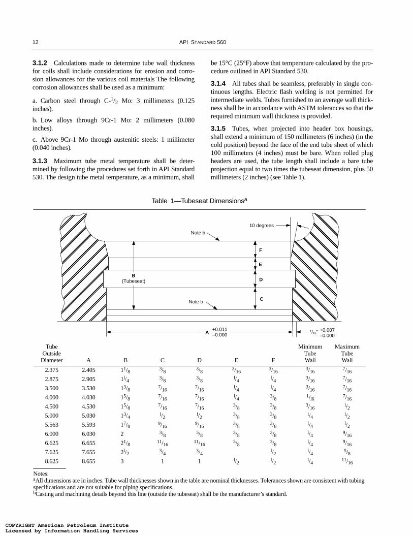
3.1.5 Tubes, when projected into header box housings,shall extend a minimum of 150 millimeters (6 inches) (in thecold position) beyond the face of the end tube sheet of which100 millimeters (4 inches) must be bare. When rolled plugheaders are used, the tube length shall include a bare tubeprojection equal to two times the tubeseat dimension, plus 50millimeters (2 inches) (see Table 1).
Table 1—Tubeseat Dimensionsa
TubeOutside
Diameter A B C D E F
MinimumTubeWall
MaximumTubeWall
2.375 2.405 11/8 3/8 3/8 3/163/16
3/167/16
2.875 2.905 1l/4 3/8 3/8 l/4 l/4 3/167/16
3.500 3.530 13/8 7/167/16
l/4 l/4 3/167/16
4.000 4.030 15/8 7/167/16
l/4 3/8 1/l6 7/16
4.500 4.530 15/8 7/167/16
3/8 3/8 3/16l/2
5.000 5.030 13/4 l/2 l/2 3/8 3/8 l/4 l/25.563 5.593 17/8 9/16
9/163/8 3/8 l/4 l/2
6.000 6.030 2 3/8 5/8 3/8 3/8 l/4 9/16
6.625 6.655 21/8 11/1611/16
3/8 3/8 l/4 9/16
7.625 7.655 2l/2 3/4 3/4 l/2 l/4 5/88.625 8.655 3 1 1 l/2 l/2 l/4 11/16
Notes:aAll dimensions are in inches. Tube wall thicknesses shown in the table are nominal thicknesses. Tolerances shown are consistent with tubing specifications and are not suitable for piping specifications.bCasting and machining details beyond this line (outside the tubeseat) shall be the manufacturer’s standard.
�������� �
�����������
+0.011–0.000A
C
F
E
DB
(Tubeseat)
Note b
Note b
10 degrees
+0.007–0.000
1/16"
COPYRIGHT American Petroleum InstituteLicensed by Information Handling ServicesCOPYRIGHT American Petroleum InstituteLicensed by Information Handling Services

FIRED HEATERS FOR GENERAL REFINERY SERVICE 13
3.1.6 Tube size (outside diameter, in inches) shall beselected from the following sizes: 2.375; 2.875; 3.50; 4.00;4.50; 5.563; 6.625; 8.625; or 10.75. Other tube sizes shouldbe used only if warranted by special process considerations.
3.1.7 When the shield and radiant tubes are in the same ser-vice, the shield tubes exposed to direct flame radiation shallbe of the same material and thickness as the connecting radi-ant tubes.
3.2 EXTENDED SURFACE
3.2.1 The extended surface in convection sections may bestudded, where each stud is attached to the tube by arc orresistance welding; or finned, where helically wound fins arecontinuously welded to the tube.
3.2.2 Metallurgy for the extended surface shall be selectedon the basis of maximum calculated tip temperature as listedin Table 2.
3.2.3 Extended surface dimensions shall be limited to thoselisted in Table 3.
3.3 MATERIALS
Tube materials shall conform to ASTM specifications aslisted in Table 4. For any material not listed in Table 4, referto 3.1.1.
4 Headers
4.1 GENERAL
4.1.1 The design stress for headers shall not be higher thanthat allowed for similar materials as shown in API Standard530 and shall be reduced by casting factors where applicable.Casting factors shall be based on ASME B31.3.
4.1.2 Headers shall be of the same metallurgy as the tubes.
4.1.3 Headers shall be welded return bends or rolled andwelded plug headers, depending on the service and operatingconditions.
4.1.4 The specified header wall thickness shall include anallowance for erosion and corrosion. This allowance shall notbe less than that used for the tubes.
4.2 PLUG HEADERS
4.2.1 Plug headers shall be located in a header box andshall be selected for the same design pressure as the connect-ing tubes and for a design temperature equal to the maximumfluid operating temperature at that location plus a minimumof 30°C (55°F).
4.2.2 Tubes and plug headers shall be arranged so thatthere is sufficient space for field maintenance operations suchas rolling, welding, and stress relieving.
4.2.3 When plug headers are specified to permit mechani-cal cleaning of coked or fouled tubes, they shall consist of thetwo-hole type. Single-hole, 180-degree, plug headers may beinstalled only for tube inspection and draining. When piggingis the mechanical cleaning method, contoured plugs arerequired. The contoured plug top must be clearly marked toassure proper orientation.
4.2.4 When plug headers are specified and horizontal tubesare 18.3 meters (60 feet) or longer, two-hole plug headersshall be used for both ends of the coil assembly. For shorterlength coils, plug headers shall be provided on one end of thecoil with welded return bends on the opposite end.
4.2.5 When plug headers are specified for vertical tubeheaters, two-hole plug headers shall be installed on the top ofthe coil and one-hole, Y-fittings at the bottom of the tubes.
●
●
Table 3—Extended Surface Dimensions
Studs Fins
MinimumDiameter
MaximumHeight
MinimumNormal Thickness
MaximumHeight
MaximumDensity
Fuel mm Inches mm Inches mm Inches mm Inches Per mm Per Inch
Gas 12.7 1/2 25.4 1 1.3 0.05 25.4 1 197 5
Oil 12.7 1/2 25.4 1 2.5 0.10 19.1 3/4 118 3
Table 2—Extended Surface Materials
Maximum TipTemperature
Maximum TipTemperature
Stud Material °C °F Fin Material °C °F
Carbon steel 510 950 Carbon steel 454 850
21/4Cr-1Mo,5Cr-1/2Mo 593 1100 — — —
11-13 Cr 649 1200 11-13 Cr 593 1100
18Cr-8Ni 18Cr-8Ni stainless steel 815 1500 stainless steel 815 1500
25Cr-20Ni 25Cr-20Ni stainless steel 982 1800 stainless steel 982 1800
●
COPYRIGHT American Petroleum InstituteLicensed by Information Handling ServicesCOPYRIGHT American Petroleum InstituteLicensed by Information Handling Services

14 API STANDARD 560
4.2.6 Headers and corresponding plugs shall be matchmarked with 13 millimeter (1/2 inch) high permanent numer-als and installed in accordance with a fitting location drawing.
4.2.7 Type 304 stainless steel thermowells, when requiredfor temperature measurement and control, shall be providedin the plugs of the headers.
4.2.8 Tube center-to-center dimensions shall be as shownin Table 5.
4.2.9 Dimensions of the tubeseat shall conform to detailsshown in Table 1 for tube wall thickness within the limitsshown. Dimensions for tube walls thinner or thicker thanshown in Table 1 are not within the scope of this standard.
4.2.10 Plugs and screws shall be assembled in the fittingswith an approved compound on the seats and screws to pre-vent galling.
4.3 RETURN BENDS
4.3.1 Return bends are preferred for the following condi-tions:
a. In clean service, where coking or fouling of tubes is notanticipated. b. Where leakage is a hazard.c. Where steam-air decoking facilities are provided fordecoking of furnace tubes.d. When pigging is the mechanical cleaning method.
4.3.2 Return bends inside the firebox shall be selected forthe same design pressure and temperature as the connectingtubes. Return bends inside a header box shall be selected forthe same design pressure as the connecting tubes and for adesign temperature equal to the maximum fluid operatingtemperature at that location plus the temperature allowancespecified on the data sheets, typically a minimum of 30°C(55°F). Return bends shall be at least the same thickness asthe connecting tubes.
4.3.3 Regardless of the location of the welded return bends,the heater design shall incorporate some means to permit con-venient removal and replacement of tubes and return bends.
4.3.4 Longitudinally welded fittings are not permitted.
Table 4—Tube Materials and ASTM Specifications
Material Pipe Specification Tube Specification
Carbon steel A 53, A 106, Gr B A 161, A 192, A 210, Gr A-1
Carbon-1/2Mo A 335 Gr P1 A 161, A 209, Gr T1
11/4Cr-1/2Mo A 335, Gr P11 A 200, A 213, Gr T11
21/4Cr-1Mo A 335, Gr P22 A 200, A 213, Gr T22
3Cr-1Mo A 335, Gr P21 A 200, A 213, Gr T21
5Cr-1/2Mo A 335, Gr P5 A 200, A 213, Gr T5
5Cr-1/2Mo-Si A 335, Gr PS5b A 213, Gr TSb
7Cr-1/2Mo A 335, Gr P7 A 200, A 213, Gr T7
9Cr-1Mo A 335, Gr P9 A 200, A 213, Gr T9
9Cr-1Mo-V A 335, Gr P91 A 200, A 213, Gr T91
18Cr-8Ni A 312, A 376, TP 304and TP 304H and TP 304L
A 213, A 271, TP 304and TP 304H and TP 304L
16Cr-12Ni-2Mo A 312, A 376, TP 316and TP 316H and TP 316L
A 213, A 271, TP 316 and TP 316H and TP 316L
18Cr-13Ni-3Mo A 312, TP 317 and TP 317L
A213, TP 317 and TP 317L
18Cr-10Ni-Ti A 312, A 376, TP 321and TP 321H
A 213, A 271, TP 321and TP 321H
18Cr-10Ni-Cb A 312, A 376, TP347and TP 347H
A 213, A 271, TP 347and TP 347H
Alloy 800H /HTa B 407 B 407
Cast 25Cr-20Ni A608, Gr HK40 —
aWith minimum grain size of ASTM #5 or coarser.
Table 5—Tube Center-to-Center Dimensionsa
Tube Size Outside
Diameter (Inches)
Header Center-to-Center Dimension
Preferred Minimum for Rolling
mm Inches mm Inches
2.375 101.6 4.00b,c 108.0 4.25
2.875 127.0 5.00b,c 120.7 4.75
3.50 152.4 6.00b 149.2 5.875
4.00 177.8 7.00b 165.1 6.50
4.50 203.2 8.00b 181.0 7.125
5.00 228.6 9.00 196.9 7.75
5.563 254.0 10.00b 215.9 8.50
6.00 279.4 11.00 228.6 9.00
6.625 304.8 12.00b 247.7 9.75
7.625 355.6 14.00 304.8 12.00
8.625 406.4 16.00b 355.6 14.00
10.75 508.0 20.00b 457.2 18.00
aCenter-to-center dimensions are applicable only to manufacturer’s standard header pressure ratings for 850 pounds per square inch gauge nominal fittings.bThis center-to-center dimension equals two times the correspond-ing nominal size and is based on the center-to-center dimension for short-radius welded return bends.cThis center-to-center dimension is inadequate for the tubeseat detail specified by Table 1 of this specification; hence this center-to-center dimension is applicable only to welded plug headers.
COPYRIGHT American Petroleum InstituteLicensed by Information Handling ServicesCOPYRIGHT American Petroleum InstituteLicensed by Information Handling Services
FIRED HEATERS FOR GENERAL REFINERY SERVICE 15
4.4 MATERIALS
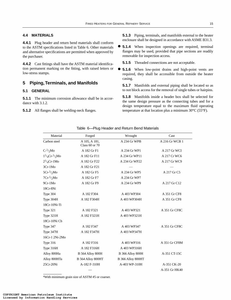
4.4.1 Plug header and return bend materials shall conformto the ASTM specifications listed in Table 6. Other materialsand alternative specifications are permitted when approved bythe purchaser.
4.4.2 Cast fittings shall have the ASTM material identifica-tion permanent marking on the fitting, with raised letters orlow-stress stamps.
5 Piping, Terminals, and Manifolds
5.1 GENERAL
5.1.1 The minimum corrosion allowance shall be in accor-dance with 3.1.2.
5.1.2 All flanges shall be welding-neck flanges.
5.1.3 Piping, terminals, and manifolds external to the heaterenclosure shall be designed in accordance with ASME B31.3.
5.1.4 When inspection openings are required, terminalflanges may be used, provided that pipe sections are readilyremovable for inspection access.
5.1.5 Threaded connections are not acceptable.
5.1.6 When low-point drains and high-point vents arerequired, they shall be accessible from outside the heatercasing.
5.1.7 Manifolds and external piping shall be located so asto not block access for the removal of single tubes or hairpins.
5.1.8 Manifolds inside a header box shall be selected forthe same design pressure as the connecting tubes and for adesign temperature equal to the maximum fluid operatingtemperature at that location plus a minimum 30°C (55°F).
●
●
Table 6—Plug Header and Return Bend Materials
Material Forged Wrought Cast
Carbon steel A 105, A 181,Class 60 or 70
A 234 Gr WPB A 216 Gr WCB 1
C-1/2Mo A 182 Gr F1 A 234 Gr WP1 A 217 Gr WCI
11/4Cr-1/2Mo A 182 Gr F11 A 234 Gr WP11 A 217 Cr WC6
21/4Cr-1Mo A 182 Gr F22 A 234 Gr WP22 A 217 Gr WC9
3Cr-1Mo A 182 Gr F21 — —
5Cr-1/2Mo A 182 Gr F5 A 234 Gr WP5 A 217 Gr C5
7Cr-1/2Mo A 182 Gr F7 A 234 Gr WP7
9Cr-1Mo A 182 Gr F9 A 234 Gr WP9 A 217 Gr C12
18Cr-8Ni
Type 304 A 182 F304 A 403 WP304 A 351 Gr CF8
Type 304H A 182 F304H A 403 WP304H A 351 Gr CF8
18Cr-10Ni-Ti
Type 321 A 182 F321 A 403 WP321 A 351 Gr CF8C
Type 321H A 182 F321H A 403 WP321H
18Cr-10Ni Cb
Type 347 A 182 F347 A 403 WP347 A 351 Gr CF8C
Type 347H A 182 F347H A 403 WP347H
16Cr-1 2Ni-2Mo
Type 316 A 182 F316 A 403 WP316 A 351 Gr CF8M
Type 316H A 182 F316H A 403 WP316H
Alloy 800Ha B 564 Alloy 800H B 366 Alloy 800H A-351 CT-15C
Alloy 800HTa B 564 Alloy 800HT B 366 Alloy 800HT
25Cr-20Ni A-182 F-310H A-403 WP-310H A-351 CK-20
— A-351 Gr HK40
aWith minimum grain size of ASTM #5 or coarser.
COPYRIGHT American Petroleum InstituteLicensed by Information Handling ServicesCOPYRIGHT American Petroleum InstituteLicensed by Information Handling Services
16 API STANDARD 560
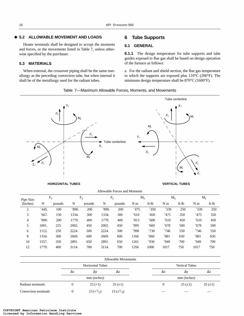
5.2 ALLOWABLE MOVEMENT AND LOADS
Heater terminals shall be designed to accept the momentsand forces, or the movements listed in Table 7, unless other-wise specified by the purchaser.
5.3 MATERIALS
When external, the crossover piping shall be the same met-allurgy as the preceding convection tube, but when internal itshall be of the metallurgy used for the radiant tubes.
6 Tube Supports
6.1 GENERAL
6.1.1 The design temperature for tube supports and tubeguides exposed to flue gas shall be based on design operationof the furnace as follows:
a. For the radiant and shield section, the flue gas temperatureto which the supports are exposed plus 110°C (200°F). Theminimum design temperature shall be 870°C (1600°F).
●
Table 7—Maximum Allowable Forces, Moments, and Movements
Allowable Forces and Moments
Pipe Size(Inches)
Fx Fy Fz Mx My Mz
N pounds N pounds N pounds N m ft-lb N m ft-lb N m ft-lb
2 445. 100 890. 200 890. 200 475 350 339 250 339 250
3 667. 150 1334. 300 1334. 300 610 450 475 350 475 350
4 890. 200 1779. 400 1779. 400 813 600 610 450 610 450
5 1001. 225 2002. 450 2002. 450 895 660 678 500 678 500
6 1112. 250 2224. 500 2224. 500 990 730 746 550 746 550
8 1334. 300 2669. 600 2669. 600 1166 860 881 650 881 650
10 1557. 350 2891. 650 2891. 650 1261 930 949 700 949 700
12 1779. 400 3114. 700 3114. 700 1356 1000 1017 750 1017 750
Allowable Movements
Horizontal Tubes Vertical Tubes
∆x ∆y ∆z ∆x ∆y ∆z
mm (inches) mm (inches)
Radiant terminals 0 25 (+1) 25 (±1) 0 25 (±1) 25 (±1)
Convection terminals 0 13 (+1/2) 13 (±1/2) — — —
Fy
My
Y+
Fz
Mz
Z+
Fx
Mx
X+
Fy
My
Y+
Fz
Mz
Z+
Fx Mx
X+
HORIZONTAL TUBES VERTICAL TUBES
Tube centerline
Tube centerline
COPYRIGHT American Petroleum InstituteLicensed by Information Handling ServicesCOPYRIGHT American Petroleum InstituteLicensed by Information Handling Services

FIRED HEATERS FOR GENERAL REFINERY SERVICE 17
b. For the convection section, the temperature of the fluegases in contact with the support plus 55°C (100°F).
c. The maximum flue gas temperature gradient across a sin-gle convection intermediate tube support shall be 250°C(400°F).
d. No credit shall be taken for the insulating effect of refrac-tory coatings on intermediate supports or guides.
6.1.2 Tube guides, radiant section intermediate tube sup-ports, and top supports for vertical radiant tubes shall bedesigned to permit their replacement without tube removaland with minimum refractory repair.
6.1.3 The unsupported length of horizontal tubes shall notexceed 35 times the outside diameter or 6 meters (20 feet),whichever is less.
6.1.4 The minimum corrosion allowance each side for allexposed surfaces of each tube support and guide contactingflue gases shall be 1.3 millimeters (0.05 inch) for austeniticmaterials and 2.5 millimeters (0.10 inch) for ferritic-materials.
6.1.5 End tubesheets for tubes with external headers shallbe designed as described in 6.1.5.1 through 6.1.5.4.
6.1.5.1 Tubesheets shall be structural plate. If the tubesheetdesign temperature exceeds 425°C (800°F), alloy materialsshall be used.
6.1.5.2 Minimum thickness of tubesheets shall be 13 milli-meters (0.5 inch).
6.1.5.3 Tubesheets shall be insulated on the flue gas sidewith a castable refractory, having a minimum thickness of 75millimeters (3 inches) for the convection section and 125 mil-limeters (5 inches) for the radiant section. As a minimum,Type 304 stainless steel anchors shall be used.
6.1.5.4 Sleeves with an inside diameter at least 13 millime-ters (0.5 inch) greater than the tube or the extended surfaceoutside diameter shall be welded to the tubesheet at each tubehole, to prevent the refractory from being damaged by thetubes. The sleeve material shall be Type 304 stainless steel.
6.1.6 Extended surface tubes shall be supported asdescribed in 6.1.6.1 through 6.1.6.3.
6.1.6.1 Intermediate supports shall be designed to preventmechanical damage to the extended surface and shall permiteasy removal and insertion of the tubes without binding.
6.1.6.2 For studded tubes, a minimum of three rows ofstuds shall rest on each support.
6.1.6.3 For finned tubes, a minimum of five fins shall reston each support.
6.2 LOADS AND ALLOWABLE STRESS
6.2.1 Tube support loads shall be determined as describedin 6.2.1.1 through 6.2.1.3.
6.2.1.1 Loads shall be determined in accordance withacceptable procedures for supporting continuous beams onmultiple supports. (e.g., AISC)
6.2.1.2 Friction loads shall be based on a minimum frictioncoefficient of 0.30.
6.2.1.3 Friction loads shall be based on all tubes expandingand contracting in the same direction. Loads shall not be con-sidered to be cancelled or reduced due to tubes moving inopposite directions.
6.2.2 Tube support maximum allowable stresses at designtemperature shall not exceed the following:
a. Dead load stress:
1. One-third of the ultimate tensile strength.
2. Two-thirds of the yield strength (0.2 percent offset).
3. Fifty percent of the average stress required to produce1 percent creep in 10,000 hours.
4. Fifty percent of the average stress required to producerupture in 10,000 hours.
b. Dead load plus frictional stress:
1. One-third of the ultimate tensile strength.
2. Two-thirds of the yield strength (0.2 percent offset).
3. The average stress required to produce 1 percent creepin 10,000 hours.
4. The average stress required to produce rupture in10,000 hours.
6.2.3 For castings, a casting factor multiplier of 0.8 shall beapplied to the allowable stress value.
6.2.4 Stress data are presented in Appendix D.
6.3 MATERIALS
6.3.1 Tube support materials shall be selected for maxi-mum design temperatures as shown in Table 8. Other materi-als and alternative specifications must be approved by thepurchaser.
6.3.2 If the tube support design temperature exceeds 650°C(1200°F) and the fuel contains more than 100 parts per mil-lion total vanadium and sodium, the supports shall be one ofthe following design details:
a. Covered with 50 millimeters (2 inches) of castable refrac-tory having a minimum density of 2081 kilograms per cubicmeter (130 pounds per cubic foot).b. Constructed of 50Cr-50Ni-Cb metallurgy, as a minimum,without any coating.
●
COPYRIGHT American Petroleum InstituteLicensed by Information Handling ServicesCOPYRIGHT American Petroleum InstituteLicensed by Information Handling Services

18 API STANDARD 560
7 Refractories and insulation
7.1 GENERAL
7.1.1 The temperature of the outside casing of the radiantand convection sections and hot ductwork shall not exceed82°C (180°F) at an ambient temperature of 27°C (80°F) withzero wind velocity. Radiant floors shall not exceed 91°C(195°F).
7.1.2 Walls, arches, and floors shall be designed to allowfor proper expansion of all parts. Where multilayer or multi-component linings are used, joints shall not be continuousthrough the lining.
7.1.3 Any layer of refractory shall be suitable for a ser-vice temperature at least 167°C (300°F) above its calculatedhot face temperature. Minimum service temperature forrefractories shall be 982°C (1800°F) in the radiant andshield sections.
7.1.4 The floor hot surface shall be a 21/2-inch thick layerof high-duty fireclay brick or a 75 millimeters (3-inch) thicklayer of castable of 1371°C (2500°F) service temperature andminimum cold crush strength of 3447 kilopascals (500pounds per square inch) after drying at 110°C (230°F).
7.1.5 Burner blocks shall have a minimum service temper-ature of 1650°C (3000°F).
7.1.6 Expansion joints shall be provided around burnerblocks, brick, and prefired shapes.
7.1.7 Target walls with flame impingement on both sidesshall be constructed of high-duty firebrick of at least 1538°C(2800°F) rating. Bricks may be laid dry or with mortaredjoints. Expansion joint gaps shall be packed with ceramic
fiber strips having a service temperature rating equal to orgreater than the brick.
Target walls with flame impingement on one side may beconstructed of brick or of plastic refractory of equivalentmaximum service temperature. Either refractory choice maybe backed by a castable or ceramic fiber board.
7.1.8 Access doors shall be protected from direct radiationby a refractory system of at least the same thermal rating andresistance as the adjacent wall lining.
7.1.9 Refractory anchors are not mandatory for floorcastable unless required for shipping considerations.
7.1.10 Maximum temperatures for anchor tips are listed inTable 9.
7.1.11 Recommended refractory dryout procedure shall beprovided by the heater vendor.
7.2 BRICK AND TILE CONSTRUCTION
7.2.1 Brick construction can be used for gravity walls,floors, or as hot-face layers.
7.2.2 Radiant chamber walls of gravity construction shallnot exceed 7.3 meters (24 feet) in height and shall be con-structed of at least high-duty fireclay brick. The base widthshall be a minimum of 8 percent of wall height. The height-to-width ratio of each wall section shall not exceed 5 to 1. Thewalls shall be self-supporting and the wall base shall restdirectly on the steel floor, not on other refractory.
7.2.3 Gravity walls shall be of mortared construction. Themortar shall be non-slagging, air-setting and chemically com-patible with adjacent refractory, including the rated tempera-ture of the brick.
Table 8—Maximum Design Temperatures for Tube Support Materials
Maximum Design Temperature
°C °F Material Casting Plate
427 800 Carbon steel A 216 Gr WCB A 283 Gr C
649 1200 21/4Cr-1Mo A 217 Gr WC 9 A 387 Gr 22, C1.1
649 1200 5 Cr-1/2Mo A 217 Gr C5 A 387 Gr 5, C1.1
816 1500 19Cr-9Ni A 297 Gr HF A 240, Type 304H
871 1600 25Cr-12Ni A 240, Type 309H
982 1800 25Cr-12Ni A 447 Type II
871 1600 25Cr-20Ni A240, Type 310H
1093 2000 25Cr-20Ni A 351 Gr HK40
982 1800 50Cr-50Ni-Cb A 560 Gr 50Cr-50Ni-Cb
Note: For exposed radiant and shield section tube supports, the material shall be 25Cr-12Ni as a minimum.
●
COPYRIGHT American Petroleum InstituteLicensed by Information Handling ServicesCOPYRIGHT American Petroleum InstituteLicensed by Information Handling Services
FIRED HEATERS FOR GENERAL REFINERY SERVICE 19
7.2.4 Vertical expansion joints shall be provided at gravitywall ends and required intermediate locations. All expansionjoints shall be kept open and free to move. If the joint isformed with lapped brick no mortar shall be used (i.e., a dryjoint).
7.2.5 Floor brick shall not be mortared. A 13 millimeter(1/2-inch) gap for expansion shall be provided on 1.8 meter(6 foot) intervals. This gap may be packed with fibrousrefractory material in strip, not loose bulk, form.
7.2.6 Minimum service temperature for a hot face bricklayer shall be 1538°C (2800°F) on walls with expected flameimpingement and 1260°C (2300°F) for other exposed wallapplications. Minimum service temperature for shieldedwalls shall be 1093°C (2000°F).
7.2.7 All brick linings on vertical flat casing shall be sup-ported by and tied back to the structural steel framing mem-bers. All tie members shall be austenitic alloy material, exceptthat pipe supports located in the backup layer may be carbonsteel. A minimum of 15 percent of the bricks shall be tiedback. Brick linings on cylindrical casing need not be tiedback when the radius of the curvature of the casing keys thebricks.
7.2.8 Brick linings shall be supported by metal supportshelves (lintels) attached to the casing on vertical centers notto exceed 1.8 meters (6 feet). Support shelves shall be slottedto provide for differential thermal expansion. Shelf materialshall be defined by the calculated service temperature; carbonsteel is satisfactory up to 371°C (700°F).
7.2.9 Expansion joints shall be provided in both verticaland horizontal directions of the walls, at wall edges, andabout burner tiles, doors, and sleeved penetrations.
7.3 CASTABLE CONSTRUCTION
7.3.1 Hydraulic-setting castables are suitable as lining forall parts of fired heaters. Minimum castable construction is a
1:2:4 volumetric mix of lumnite-haydite-vermiculite, limitedto a maximum service temperature rating of 1038°C (1900°F)and clean fuel applications. This castable shall be limited to200 millimeters (8-inch) maximum thickness on arches andwalls.
7.3.2 For dual layer castable construction, the hot facelayer shall be a minimum of 75 millimeters (3 inches) thick.The anchoring systems shall provide independent support foreach layer when in arch or other overhead position.
7.3.3 Anchoring penetration shall not be less than 70 per-cent of the individual layer being anchored for castable thick-ness greater than 50 millimeters (2 inches). The anchor shallnot be closer than 13 millimeters (1/2 inch) from the hot face.
7.3.4 The anchoring spacing shall be a maximum of threetimes the total lining thickness but shall not exceed 300 milli-meters (12 inches) on a square pattern for walls and 230 mil-limeters (9 inches) on a square pattern for arches. The anchororientation shall be varied to avoid creating continuous shearplanes.
7.3.5 Anchors for total castable thickness up to 150 milli-meters (6 inches) shall be a minimum of 5 millimeters (3/16inch) diameter. Greater refractory thicknesses require a mini-mum of 6 millimeters (1/4 inch) diameter anchors.
7.3.6 Castable linings in header boxes, breechings, andlined flue gas ducts and stacks shall not be less than 50 milli-meters (2 inches) thick.
7.3.7 Anchors in 50 millimeters (2-inch) thick castable lin-ings shall be held in place by 10 gauge minimum, carbonsteel chain-link fencing, wire mesh, or linear anchors weldedto the steel casing.
7.3.8 When metallic fiber is added for reinforcement itshall only be used in castables of 880 kilograms per cubicmeter (55 pounds per cubic foot) or greater density. Metallicfibers shall be limited to no more than 3 percent by weight ofthe dry mixture.
7.3.9 Low iron content (maximum of 1.5%) materials shallbe used when total heavy metals content within fuels exceeds100 parts per million.
7.3.10 Hydraulic setting castables, in particular lightweightand medium weight insulating castables are susceptible to thedevelopment of alkaline hydrolysis (carbonization) whenplaced under high ambient temperatures and/or high humidityconditions shortly after placement.
To reduce the tendency for hydraulic setting castables todevelop alkaline hydrolysis, an application of an imperviousorganic coating shall be applied immediately after castableplacement and reapplication of the same coating shortly afterthe twenty-four (24) hour cure.
Table 9—Maximum Temperatures for Anchor Tips
Maximum Anchor Temperature
Anchor Material °F °C
Carbon steel 800 427
TP 304 stainless steel 1400 760
TP 316 stainless steel 1400 760
TP 309 stainless steel 1500 815
TP 310 stainless steel 1700 927
RA 330 stainless steel 1900 1038
Alloy 601 2000 1093
Ceramic studs and washers >2000 >1093
COPYRIGHT American Petroleum InstituteLicensed by Information Handling ServicesCOPYRIGHT American Petroleum InstituteLicensed by Information Handling Services
20 API STANDARD 560
The use of forced drying by air movement or low tempera-ture to remove a percentage of the mechanical water prior tothe application of the impervious coating can further reducethe possibility of development of alkaline hydrolysis. Alka-line hydrolysis is a naturally occurring phenomenon such thatthe use of either or both of the above procedures may notentirely prevent the formation thereof.
In instances where alkaline hydrolysis has occurred theloss in refractory thickness is usually less than 10 millimeters(3/8 inch). When this occurs, the loose material shall bebrushed off and an impervious organic coating applied.
7.4 CERAMIC FIBER CONSTRUCTION
7.4.1 Ceramic fiber in layered or modular constructionmay be used in all heater areas except stacks, ducts, andfloors.
7.4.2 The hot face of layered ceramic fiber blanket installa-tions shall be a minimum of 25 millimeters (1 inch) thick, 128kilograms per cubic meter (8 pounds per cubic foot) density,needled material. Ceramic fiber board, when applied as a hotface layer, shall not be less than 38 millimeters (11/2-inch)thick nor less than 240 kilograms per cubic meter (15 poundsper cubic foot) density. Backup layer(s) of ceramic fiber blan-ket shall be a minimum of 96 kilograms per cubic meter (6pounds per cubic feet) density, needled material. Ceramicfiber board size, when used as hot face layer, shall be limitedto a maximum of 610 millimeters by 610 millimeters (24inches by 24 inches) when temperatures are below 1093°C(2000°F) and 460 millimeters by 460 millimeters (18 inchesby 18 inches) when temperatures exceed 1093°C (2000°F).
7.4.3 Any layer of ceramic fiber shall be suitable for a ser-vice temperature at least 260°C (500°F) above its calculatedhot face temperature.
7.4.4 The hot face layer of a ceramic fiber blanket systemshall be anchored a maximum of 76 millimeters (3 inches)from all edges.
7.4.5 The anchor spacing for arches shall not exceed thefollowing rectangular pattern: 150 millimeters by 230 milli-meters (6 inches by 9 inches) for 305 millimeters (12-inch)wide blankets; 230 millimeters by 230 millimeters (9 inchesby 9 inches) for 610 millimeters (24-inch) wide blankets; 230millimeters by 250 millimeters (9 inches by 10 inches) for915 millimeters (36-inch) wide blankets; and 230 millimetersby 270 millimeters (9 inches by 101/2-inches) for 1220 milli-meters (48-inch) wide blankets.
7.4.6 The anchor spacing for walls shall not exceed the fol-lowing rectangular pattern: 150 millimeters x 230 millimeters(6 inches by 9 inches) for 305 millimeters (12) wide blankets;270 millimeters by 305 millimeters (9 inches by 12 inches)for 610 millimeters (24-inch) wide blankets; and 270 milli-
meters by 305 millimeters (101/2-inches by 12 inches) for1220 millimeters (48-inch) wide blankets.
7.4.7 Metallic anchor parts that are not shielded by tubesshall be completely wrapped with ceramic fiber patches or beprotected by ceramic retainer cups filled with moldableceramic fiber.
7.4.8 Ceramic fiber blanket is unacceptable to be used asthe hot face layer when flue gas velocities are in excess of12.2 meters per second (40 feet per second). Wet blanket,ceramic fiber board, or ceramic fiber modules shall be usedon hot face layers with velocities greater than 12.2 meters persecond (40 feet per second) but less than 24.4 meters per sec-ond (80 feet per second). Hot face refractory with velocitiesgreater than 24.4 meters per second (80 feet per second)require castable or external lining.
7.4.9 Ceramic fiber blanket shall be installed with its long-est dimension in the direction of gas flow. The hot face layerof blanket shall be constructed with all joints overlapped.Overlaps shall be in the direction of gas flow. Hot face layersof ceramic fiber board shall be constructed with tight buttjoints.
7.4.10 Ceramic fiber blanket used in backup layers shall beinstalled with butt joints, with at least 25 millimeters (1 inch)compression on the joints. All joints in successive layers ofblanket shall be staggered.
7.4.11 Ceramic fiber blanket modules shall be installed insoldier course (with batten strips) patterns. Parquet patternsare acceptable in arch areas only.
7.4.12 Module systems shall be installed so that joints ateach edge are compressed to avoid gaps due to shrinkage.
7.4.13 Modules applied in arches shall be designed suchthat anchorage is provided over at least 80 percent of themodule width.
7.4.14 Anchors shall be attached to the casing before mod-ules are installed.
7.4.15 Anchor assembly shall be located in the module at amaximum distance of 2 inches (50 millimeters) from themodule cold face.
7.4.16 Module internal hardware shall be Type 304 stain-less steel as a minimum.
7.4.17 When ceramic fiber construction is used with fuelshaving a sulfur content exceeding 10 parts per million, thecasing shall have an internal protective coating to prevent cor-rosion. The protective coating shall be rated for 177°C(350°F) service temperature.
7.4.18 A vapor barrier of Type 304 stainless steel foil shallbe provided when the fuel sulfur content exceeds 500 parts
●
COPYRIGHT American Petroleum InstituteLicensed by Information Handling ServicesCOPYRIGHT American Petroleum InstituteLicensed by Information Handling Services
FIRED HEATERS FOR GENERAL REFINERY SERVICE 21
per million. The vapor barrier must be located so that theexposure temperature is at least 56°C (100°F) above the cal-culated acid dew point for all operating cases. Vapor barrieredges shall be overlapped; edges and punctures shall besealed.
7.4.19 Ceramic fiber systems shall not be applied for ser-vices where the total heavy metals content in the fuel exceeds100 parts per million.
7.4.20 Ceramic fiber shall not be used in convection sec-tions where soot blowers, steam lances, or waterwash facili-ties are initially provided.
7.4.21 Anchors shall be installed before applying protec-tive coating to the casing. The coating shall cover theanchors so that uncoated parts are above the acid dew pointtemperature.
7.5 MULTICOMPONENT LINING CONSTRUCTION
7.5.1 Castable layers shall be a minimum of 76 millimeters(3 inches) thick.
7.5.2 The anchoring system shall provide retention andsupport for each component layer.
7.5.3 Anchor types and installation for individual liningcomponents shall meet the applicable requirements of 7.2,7.3, and 7.4.
7.5.4 The material used in any layer shall be suitable forservice temperature in accordance with 7.1.3 and 7.4.3.
7.5.5 Brick may be used for hot face service or as a backuplayer if the hot face layer is brick.
7.5.6 Block insulation shall be calcium silicate or min-eral wool fiber with a minimum service temperature ratingof 983°C (1800°F). Block insulation shall only be used asa backup material, but shall not be used when the fuel sul-fur content exceeds 1 percent by weight in liquid fuel or100 parts per million hydrogen sulfide in gas fuel. Blockinsulation shall not be used as backup material in floorconstruction.
7.5.7 When insulating block or ceramic fiber is used asbackup insulation, the casing shall have a protective coatingif the fuel sulfur content exceeds 10 parts per million. Theprotective coating shall be rated for 177°C (350°F) servicetemperature.
7.5.8 When used as backup for castable, block insulationor ceramic fiber shall be sealed to prevent water migrationfrom the castable.
7.5.9 Minimum density of insulating block and ceramicfiber used as backup materials shall be 128 kilograms percubic meter (8 pounds per cubic foot).
7.6 MATERIALS
7.6.1 Materials shall conform to the following ASTM spec-ifications:
a. Fireclay brick, ASTM C27.
b. Insulating firebrick, ASTM C155.
c. Castable refractory, ASTM C401, Class N, O, P, Q, or R.
d. Vermiculite sieve analysis, ASTM C332, Group 1 density.
e. Insulating block (mineral slag wool, neutral pH), ASTMC612 CL5.
f. Haydite, ASTM C332 Group II:
1. Poured application: Fine aggregate No. 4.2. Gunned application: Combined fine and coarse 10 mil-limeters (3/8 inch) to Fine Aggregate No. 0.
7.6.2 The following materials shall have a composition asshown:
a. Lumnite or calcium aluminate cement, 35 percent Al2O3or better.
b. Ceramic fiber, at least 43 percent combined total of Al2O3+ Zirconia or at least 43 percent combined total of Al2O3 +Chromia remainder primarily SiO3 or ZrO2.
8 Structures and Appurtenances
8.1 GENERAL
8.1.1 Structural steel shall be designed in accordance withthe applicable provisions of the following codes and specifi-cations (the purchaser shall set priorities if codes conflict):
a. International Conference of Building Officials, UniformBuilding Code.b. American Institute for Steel Construction, Specificationfor Design, Fabrication, and Erection of Structural Steel forBuildings.c. ASCE standards.d. Local codes as specified by purchaser.
8.1.2 Minimum design loads for wind and earthquake shallconform to requirements of the ICBO Uniform BuildingCode or ASCE 7 latest revision, and/or local codes as speci-fied by the purchaser.
8.1.3 Platform live loads shall be in accordance with theloads specified in the ICBO Uniform Building Code for heavymanufacturing facilities, or local codes as specified by thepurchaser.
8.1.4 Structures and appurtenances shall be designed for allapplicable load conditions expected during shipment, erec-tion, and operation. Cold weather conditions shall be consid-ered, particularly when the furnace is not in operation. Theseload conditions shall include, but are not limited to, deadload, wind load, earthquake load, live load, and thermal load.
●
●
●
COPYRIGHT American Petroleum InstituteLicensed by Information Handling ServicesCOPYRIGHT American Petroleum InstituteLicensed by Information Handling Services

22 API STANDARD 560
8.1.5 Design metal temperature of structures and appurte-nances shall be the calculated metal temperature plus 55°C(100°F), based on the maximum flue gas temperatureexpected for all operating modes with an ambient tempera-ture of 27°C (80°F) in still air.
8.1.6 The effect of elevated design temperature on yieldstrength and Modulus of Elasticity shall be modified in accor-dance with 9.3.5.
8.1.7 The material of the structures and appurtenances shallbe adequate for all load conditions at the lowest specifiedambient temperature when the furnace is not in operation.
8.2 STRUCTURES
8.2.1 All loads from the tubes and headers shall be sup-ported by the structural steel and shall not be transmitted intothe refractory.
8.2.2 Structural steel shall be designed to permit lateral andvertical expansion of all heater parts.
8.2.3 Heater casing shall be a minimum of 5-millimeter(3/16-inch) thick plate, which shall be reinforced againstwarping. Casing, when used to resist buckling stresses, shallbe 6 millimeters (1/4-inch) minimum thickness. Floor andradiant roof plates shall be 6 millimeters (1/4-inch) mini-mum thickness.
8.2.4 Heater casing plate shall be seal welded externally toprevent air and water infiltration.
8.2.5 The heater structure shall be capable of supportingladders, stairs, and platforms in locations where installed orwhere specified for future use.
8.2.6 Flat roof design shall allow for runoff of rainwater.This can be accomplished by arrangement of structural mem-bers and drain openings, by sloping the roof or with a second-ary roof for weather protection. When pitched roofs areprovided for weather protection, eaves and gables shall pre-vent the entry of windblown rain.
8.2.7 When fireproofing is specified, the main structuralcolumns from the base plate to the floor level plus the mainfloor beams shall allow for 50 millimeters (2 inches) of fire-proofing.
8.2.8 Heaters with horizontal tubes that have return bendsinside the firebox shall have removable end panels or panelsin the sidewalls, to provide access to the return bend welds.
8.2.9 Duct structural systems shall support duct work inde-pendent of expansion joints during operation, when idle orwith duct sections removed.
8.3 HEADER BOXES, DOORS, AND PORTS
8.3.1 Header Boxes
8.3.1.1 Each header box shall allow for the total tubeexpansion. A minimum clearance of 75 millimeters (3 inches)shall be provided between the header box door refractory andthe header in the hot position.
8.3.1.2 Header boxes enclosing plug headers shall havehinged doors or bolted end panels.
8.3.1.3 Header boxes, including doors, shall be of 5 milli-meters (3/16 inch) minimum steel plate reinforced againstwarping. Header boxes shall be removable.
8.3.1.4 When header boxes are greater than 1.5 meters (5feet) in length or when specified by purchaser, horizontal par-titions shall be provided in convection header boxes. Themaximum spacing is 1.5 meters (5 feet).
8.3.2 Doors and Ports
8.3.2.1 Two access doors having a minimum clear openingof 600 millimeters by 600 millimeters (24 inches by 24inches) shall be provided for each radiant chamber of a box orcabin heater.
8.3.2.2 One access door having a minimum clear openingof 450 millimeters by 450 millimeters (18 inches by 18inches) shall be provided in the floor for vertical cylindricalheaters. A bolted and gasketed access door shall also be pro-vided in any air plenum below the floor accessway. Wherespace is not available, access via a burner port is acceptable.
8.3.2.3 One access door having a minimum clear openingof 600 millimeters by 600 millimeters (24 inches by 24inches), or 600 millimeters (24 inches) in diameter shall beprovided in the stack or breeching for access to the damperand convection sections.
8.3.2.4 One tube removal door having a minimum clearopening of 450 millimeters by 600 millimeters (18 inches by24 inches) shall be provided in the arch of each radiant cham-ber of vertical tube heaters.
8.3.2.5 Observation doors and ports shall be provided forviewing all radiant tubes and all burner flames for properoperation and light off.
8.3.2.6 Access doors having a minimum clear opening of600 millimeters by 600 millimeters (24 inches by 24 inches)shall be provided to ducts, plenums and at all duct connec-tions to air preheaters and control dampers.
8.4 LADDERS, PLATFORMS, AND STAIRWAYS
8.4.1 Platforms shall be provided as follows:
a. At burner and burner controls that are not accessible fromgrade.
●
●
●
●
●
COPYRIGHT American Petroleum InstituteLicensed by Information Handling ServicesCOPYRIGHT American Petroleum InstituteLicensed by Information Handling Services
FIRED HEATERS FOR GENERAL REFINERY SERVICE 23
b. At both ends of the convection section for maintenancepurposes.
c. At damper and sootblower locations for maintenance andoperation purposes.
d. At all observation ports and firebox access doors notaccessible from grade.
e. At auxiliary equipment, such as steam drums, fans, driv-ers, and air preheaters as required for operating andmaintenance purposes.
8.4.2 Vertical cylindrical heaters with shell diametersgreater than 3 meters (10 feet) shall have a full circular plat-form at the floor level. Individual ladders and platforms toeach observation door may be used when shell diameters are3 meters (10 feet) or less.
8.4.3 Platforms shall have a minimum clear width as fol-lows:
a. Operating platforms, 900 millimeters (3 feet).
b. Maintenance platforms, 900 millimeters (3 feet).
c. Walkways, 750 millimeters (2 feet, 6 inches).
8.4.4 Platform decking shall be 6 millimeters (1/4 inch)checkered plate or 25 millimeters by 5 millimeters (1 inch by3/16 inch) open grating. Stair treads shall be open grating withcheckered plate nosing.
8.4.5 Dual access shall be provided to each operating plat-form except when the individual platform length is less than 6meters (20 feet).
8.4.6 An intermediate landing shall be provided when thevertical rise exceeds 9 meters (30 feet) for ladders and 4.5meters (15 feet) for stairways.
8.4.7 Ladders shall be caged from a point 2.3 meters (7feet, 6 inches) above grade or any platform. A self closingsafety gate shall be provided for all ladders serving platformsand landings.
8.4.8 Stairways shall have a minimum width of 750 milli-meters (2 feet, 6 inches), a minimum tread width of 240 milli-meters (91/2 inches), and a maximum riser of 200 millimeters(8 inches). The slope of the stairway shall not exceed a 9 (ver-tical) to 12 (horizontal) ratio.
8.4.9 Headroom over platforms, walkways, and stairwaysshall be a minimum of 2.1 meters (7 feet).
8.4.10 Handrails shall be provided on all platforms, walk-ways, and stairways.
8.4.11 Handrails, ladders, and platforms shall be arrangedso as not to interfere with tube handling. Where interferenceexists, provide removable sections.
8.4.12 All thermocouple and flue gas sampling connec-tions, as specified by purchaser, shall be accessible fromgrade, platforms or ladders.
8.4.12.1 Connections considered as accessible from a plat-form shall be no more than 2.1 m (7 feet) above the floor ofthe platform.
8.4.12.2 Connections considered as accessible from gradeshall be no more than 3 m (10 feet) above grade.
8.4.12.3 Connections considered as accessible from per-manent vertical ladders shall be no more than 0.8 m (2.5 feet)from the centerlines of such ladders and at least 0.9 m (3 feet)below the top rung of such ladders.
8.5 MATERIALS
8.5.1 Materials used in the fabrication of fired heaters shallconform to the following specifications or purchaser’sapproved equivalent specifications:
a. Structural shapes, ASTM A 36, A 242, A 572.
b. Plate, ASTM A 36, A 283 Grade C, A 242, or A 572.
c. Structural bolts, ASTM A 307, unfinished.
d. High-strength bolts, ASTM A 325 or ASTM A 490.
e. Pipe for columns and davits, ASTM A 53 Grade B.
8.5.2 Materials for service at design ambient tempera-tures below –30°C (–20°F) shall be as specified by the pur-chaser.
9 Stacks, Ducts, and Breeching
9.1 GENERAL
9.1.1 Stacks shall be self-supporting.
9.1.2 Stacks shall be bolted to their supporting structure.
9.1.3 Stacks shall be of all welded construction. Fieldsplice joints in stacks shall require full penetration welding.Breeching and ducting may be of welded or bolted con-struction.
9.1.4 External attachments to stacks shall be seal welded.
9.1.5 Stacks, breechings, and ducts mounted on concreteshall be designed to prevent concrete temperatures in excessof 149°C (300°F).
9.1.6 Connections between stacks and flue gas ducts shallnot be welded.
9.1.7 The top of stack linings shall be protected to preventwater penetration between the stack shell plate and the lining.
9.1.8 All openings and connections on stacks, breechings,and ducts shall be sealed to prevent air or flue gas leakage.
●
●
COPYRIGHT American Petroleum InstituteLicensed by Information Handling ServicesCOPYRIGHT American Petroleum InstituteLicensed by Information Handling Services

24 API STANDARD 560
9.1.9 Breechings shall have a minimum clear distancebeyond the last (present and future) convection row of 0.8meter (2 feet, 6 inches) for access and flue gas distribution.
9.1.10 When operating with natural draft, control damp-ers shall be furnished on each heater stack or each inlet airplenum.
9.2 DESIGN CONSIDERATIONS
9.2.1 The design shall be in accordance with the applicableprovisions of the following codes and specifications:
a. ICBO Uniform Building Code.
b. American Institute for Steel Construction, Specificationfor Design, Fabrication, and Erection of Structural Steel forBuildings.
c. ASCE standards.
d. Local codes as specified by the purchaser.
9.2.2 Minimum design loads for wind and earthquake shallconform to the requirements of the ICBO Uniform BuildingCode or ASCE 7, Latest Edition.
9.2.3 Stacks, breechings, and ducts shall be designed for allapplicable load conditions expected during shipment, erec-tion, and operation. Cold weather conditions shall be consid-ered, particularly when the furnace is not in operation. Theseload conditions shall include, but not be limited to, dead load,wind load, earthquake load, live load, and thermal load.
9.2.4 The combination of loads that could occur simulta-neously creating the maximum load condition shall be thedesign load, but in no case shall individual loads createstresses that will exceed those allowed by 9.3.5. Wind andearthquake loads shall not be considered as acting simulta-neously. When critical wind velocities exceed 97 kilometersper hour (60 miles per hour), dynamic loads resulting fromwind need not be included in the design load. Stacks locatedcloser than 8 diameters may be subject to increased windloads.
9.2.5 The minimum stack shell plate thickness shall be 6millimeters (1/4-inch) including corrosion allowance. Theminimum corrosion allowance on stacks shall be 1.6 millime-ters (1/16 inch) for lined stacks and 3 millimeters (1/8 inch) forunlined stack.
9.2.6 The minimum number of anchor bolts for any stackshall be eight.
9.2.7 Lifting lugs on stacks, when required, shall bedesigned for the lifting load as the stack is raised from a hori-zontal to a vertical position.
9.2.8 Design metal temperature of stacks, breechings, andducts shall be the calculated metal temperature plus 56°C(100°F), based on the maximum flue gas temperature
expected for all operating modes with an ambient tempera-ture of 27°C (80°F) in still air.
9.2.9 The material of the stack, breeching, and duct shallbe adequate for all load conditions at the lowest specifiedambient temperature when the furnace is not in operation.
9.2.10 The minimum breeching and duct plate thicknessshall be 5 millimeters (3/16 inch).
9.2.11 Breechings and ducts shall be stiffened to preventexcessive warpage and deflection. Deflection of refractorylined breechings and ducts shall be limited to 1/360th of thespan. Deflection of other breechings and ducts shall be lim-ited to 1/240th of the span.
9.2.12 Butterfly dampers shall be limited to stacks andducts having a maximum internal cross-sectional area of 1.2square meters (13 square feet).
9.2.13 Louver dampers shall have a minimum of one bladefor every 1.2 square meters (13 square feet) of internal cross-sectional area in the stack or duct. Each blade shall haveapproximately equal surface area. Blades shall have opposedmovement.
9.2.14 Damper shafts and bolting shall be of the samematerial as the blade.
9.2.15 Damper bearings and control mechanisms shall beexternal. Bearings shall be aligning, self lubricating graph-ite bearings mounted in bearing manufacturer’s standardhousing.
9.2.16 The use of unlined stacks shall be the decision ofthe owner considering location and fuel composition. Whenunlined stacks are specified the flue gas temperature shall notbe less than 204°C (400°F) nor greater than 371°C (700°F).
9.3 ALLOWABLE STRESSES
9.3.1 The maximum longitudinal stress in the stack shallnot exceed the smaller of
0.5Fy (1)
or
where:
E = material modulus of elasticity at design tempera-ture, in megapascals (pounds per square inch),
t = corroded shell plate thickness, in millimeters (inches),
●
●
0.56EtD 1 0.004E Fy⁄( )+[ ]--------------------------------------------------
COPYRIGHT American Petroleum InstituteLicensed by Information Handling ServicesCOPYRIGHT American Petroleum InstituteLicensed by Information Handling Services

FIRED HEATERS FOR GENERAL REFINERY SERVICE 25
D = outside diameter of stack shell, in millimeters (inches),
Fy = material minimum yield strength at design temper-ature, in megapascals (pounds per square inch).
9.3.2 The combined membrane and bending stress in thestack shell or stiffening rings shall not exceed 90 percent ofthe minimum yield strength of the respective material atdesign temperature.
9.3.3 The tensile stress on anchor bolts shall not exceed 138megapascals (20,000 pounds per square inch) on the AISCtensile area for ASTM A 307 material and 227 megapascals(33,000 pounds per square inch) for A 320 L7 material.
9.3.4 The tensile stress on structural bolts shall not exceed303 megapascals (44,000 pounds per square inch) on theAISC nominal area for ASTM A 325 and 227 megapascals(33,000 pounds per square inch) for ASTM A 193 B7 or A320 L7 material.
9.3.5 The minimum yield strength and modulus of elastic-ity for structural steel shall be as listed in Table 10.
9.4 STATIC DESIGN
9.4.1 All stacks shall be designed as cantilever beam col-umns.
9.4.2 Linings shall not be considered as contributing to thestrength of the stack, breeching, or duct.
9.4.3 The minimum shape factor and effective diameter forwind loads shall be as listed in Table 11.
9.4.4 Discontinuities in the stack shell plate, such as cone-to-cylindrical junctions and non-circular transitions, shall be
designed so that the combined membrane and bendingstresses do not exceed the allowable stresses.
9.4.5 Openings in stacks, breechings, and ducts shall bereinforced to provide the required section properties. For sin-gle openings in cylindrical stacks, the chord shall not exceed1.4 times the radius. For two openings, opposite each other,each chord shall not exceed the radius.
9.4.6 Changes in cylindrical stack diameters shall be madewith cones having an apex angle of 60 degrees or less.
9.4.7 Stiffening rings are required when t ≤ (5M/9Fys)1/2
and shall be provided as follows:
a. Ring spacing limits: 1 ≤ L/D ≤ 3.
b. Ring section modulus required: S, ≥ LM/0.6Fyr.
where:
M = maximum circumferential moment per unit length of shell, in newton-meter per meter (inch-pounds per inch),
Fys = minimum yield strength of shell material at design temperature, in pascals (pounds per square inch),
t = corroded shell thickness, in meters (inches),
L = ring spacing, in meters (inches),
D = shell diameter, in meters (inches),
S = section modulus of ring, in cubic meters (cubic inches),
Fyr = minimum yield strength of ring material at the shell design temperature, in pascals (pounds per square inch).
Table 10—Minimum Yield Strength and Modulus of Elasticity for Structural Steel
ASTM A-36 ASTM A-242 ASTM A-572
Fy E Fy E Fy E°C °F MPa (x 103)psi MPa (x 103) (x 106) psi MPa (x 103) psi MPa (x 103) (x 106) psi MPa (x 103) psi MPa (x 103) (x 106) psi
21 70 248 36.0 200 29.0 290 42.0 192 27.9 345 50.0 206 30.0
93 200 227 32.9 201 29.2 272 39.5 191 27.7 333 48.3 205 29.7
149 300 208 30.2 197 28.6 267 38.7 189 27.4 320 46.3 202 29.3
204 400 200 29.0 193 28.0 261 37.8 186 27.0 293 42.5 199 29.0
260 500 192 27.8 189 27.4 254 36.8 182 26.4 282 40.8 194 28.3
316 600 183 26.6 185 26.8 246 35.7 177 25.7 268 38.8 188 27.4
371 700 175 25.4 180 26.1 238 34.5 171 24.8 262 38.0 184 26.7
427 800 161 23.4 176 25.5 229 33.2 161 23.4 249 36.0 173 25.1
COPYRIGHT American Petroleum InstituteLicensed by Information Handling ServicesCOPYRIGHT American Petroleum InstituteLicensed by Information Handling Services
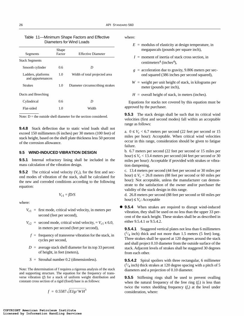
26 API STANDARD 560
9.4.8 Stack deflection due to static wind loads shall notexceed 150 millimeters (6 inches) per 30 meters (100 feet) ofstack height, based on the shell plate thickness less 50 percentof the corrosion allowance.
9.5 WIND-INDUCED VIBRATION DESIGN
9.5.1 Internal refractory lining shall be included in themass calculation of the vibration design.
9.5.2 The critical wind velocity (Vc), for the first and sec-ond modes of vibration of the stack, shall be calculated forthe new and corroded conditions according to the followingequation:
Vc1 = fD/S
where:
Vc1 = first mode, critical wind velocity, in meters per second (feet per second),
Vc2 = second mode, critical wind velocity, = Vc1 x 6.0, in meters per second (feet per second),
f = frequency of transverse vibration for the stack, in cycles per second,
D = average stack shell diameter for its top 33 percent of height, in feet (meters),
S = Strouhal number 0.2 (dimensionless).
Note: The determination of f requires a rigorous analysis of the stackand supporting structure. The equation for the frequency of trans-verse vibration (f) for a stack of uniform weight distribution andconstant cross section of a rigid (fixed) base is as follows:
where:
E = modulus of elasticity at design temperature, in megapascals (pounds per square inch),
I = moment of inertia of stack cross section, in centimeters4 (inches4),
g = acceleration due to gravity, 9.806 meters per sec-ond squared (386 inches per second squared),
W = weight per unit height of stack, in kilograms per meter (pounds per inch),
H = overall height of stack, in meters (inches).
Equations for stacks not covered by this equation must beapproved by the purchaser.
9.5.3 The stack design shall be such that its critical windvelocities (first and second modes) fall within an acceptablerange as follows:
a. 0 ≤ Vc < 6.7 meters per second (22 feet per second or 15miles per hour): Acceptable. When critical wind velocitiesoccur in this range, consideration should be given to fatiguefailure.b. 6.7 meters per second (22 feet per second or 15 miles perhour) ≤ Vc < 13.4 meters per second (44 feet per second or 30miles per hour): Acceptable if provided with strakes or vibra-tion dampening.c. 13.4 meters per second (44 feet per second or 30 miles perhour) ≤ Vc < 26.8 meters (88 feet per second or 60 miles perhour): Not acceptable, unless the manufacturer can demon-strate to the satisfaction of the owner and/or purchaser thevalidity of the stack design in this range.d. 26.8 meters per second (88 feet per second or 60 miles perhour) ≤ Vc: Acceptable
9.5.4 When strakes are required to disrupt wind-inducedvibration, they shall be used on no less than the upper 33 per-cent of the stack height. These strakes shall be as described ineither 9.5.4.1 or 9.5.4.2.
9.5.4.1 Staggered vertical plates not less than 6 millimeters(1/4 inch) thick and not more than 1.5 meters (5 feet) long.Three strakes shall be spaced at 120 degrees around the stackand shall project 0.10 diameter from the outside surface of thestack. Adjacent levels of strakes shall be staggered 30 degreesfrom each other.
9.5.4.2 Spiral spoilers with three rectangular, 6 millimeter(1/4 inch) thick strakes at 120 degree spacing with a pitch of 5diameters and a projection of 0.10 diameter.
9.5.5 Stiffening rings shall be used to prevent ovallingwhen the natural frequency of the free ring (fr) is less thantwice the vortex shedding frequency (fv) at the level underconsideration, where:
Table 11—Minimum Shape Factors and Effective Diameters for Wind Loads
SegmentsShape Factor Effective Diameter
Stack Segments
Smooth cylinder 0.6 D
Ladders, platforms and appurtenances
1.0 Width of total projected area
Strakes 1.0 Diameter circumscribing strakes
Ducts and Breeching
Cylindrical 0.6 D
Flat-sided 1.0 Width
Note: D = the outside shell diameter for the section considered.
f 0.5587 EIg W H4⁄=
●
COPYRIGHT American Petroleum InstituteLicensed by Information Handling ServicesCOPYRIGHT American Petroleum InstituteLicensed by Information Handling Services
FIRED HEATERS FOR GENERAL REFINERY SERVICE 27
where:
fr = natural frequency of free ring at level under consideration, in cycles per second,
tr = corroded plate thickness at level under consid-eration, in millimeters (inches),
E = modulus of elasticity of stack plate material at design temperature, in megapascals (pounds per square inch),
Dr = internal stack diameter at level under consider-ation, in meters (feet).
and
fv = 13.2/Dr
where:
fv = vortex shedding frequency at level under con-sideration, in cycles per second,
Dr = internal stack diameter at level under consider-ation, in meters (feet).
Both of these frequencies should be calculated at eachlevel, using the corresponding thickness (tr) and diameters(Dr). The section modulus of required stiffeners (Sm) shall notbe less than:
where:
Vc = (60)(fr)(Dr)/(2)(S),
fr = natural frequency of free ring at level under consideration, in cycles per second,
tr = corroded plate thickness at level under consid-eration, in millimeters (inches),
Dr = internal stack diameter at level under consider-ation, in meters (feet),
E = modulus of elasticity of stack plate material at design temperature, in megapascals (pounds per square inch),
fv = vortex shedding frequency at level under con-sideration, in cycles per second,
Hr = stiffening ring spacing, in meters (feet),
St = allowable tensile stress of stack plate material at design temperature, in megapascals (pounds per square inch),
S = Strouhal number 0.2 (dimensionless),
Vc = critical wind velocity for ovalling at the level under consideration, in meters per minute (feet per minute).
Source: Mahajan, Kanti H., “Tall Stack Design Simpli-fied,” Hydrocarbon Processing, p. 217, September 1975.
9.6 MATERIALS
9.6.1 Stacks, ducts, and breechings shall be constructed ofmaterials conforming to ASTM A 36 or A 242. Alternativematerials may be selected when approved by purchaser.
9.6.2 When the minimum service temperature is above -18°C (0°F), bolting material shall be per ASTM A 307, A325, or A 193 B7. Below –18°C (0°F), A 193 B7 bolts with A194 2H nuts or A 320 L7 bolting shall be used. No welding ispermitted on A 320 L7 or A 193 B7 materials.
9.6.3 Damper materials shall be limited to maximum ser-vice temperature as follows:
a. Carbon steel, 427°C (800°F).
b. 5Cr-1/2Mo, 649°C (1200°F).
c. 18Cr-8Ni, 816°C (1500°F).
d. 25Cr-12Ni, 982°C (1800°F).
9.7 ALTERNATE DESIGN METHODS
9.7.1 ISO 13705 Annex H or ASME STS-1 are acceptablealternate design criteria without owner or purchaser approval.
10 Burners, Sootblowers, and Damper Controls
10.1 BURNERS
10.1.1 Burner design and installation shall ensure againstflame impingement on tubes and tube supports when burnersare operating at maximum heat release.
10.1.2 Burners shall be designed in accordance with alllocal and national mandatory statutes and regulations.
10.1.3 For natural draft operation, with burners firing verti-cally or horizontally, the minimum clearances listed in Table12 shall be provided.
f r
0.126 tr E
Dr2
------------------------------=
Sm
7 10 7–×( ) V c( )2 Dr( )2Hr
St
--------------------------------------------------------=
●
●
COPYRIGHT American Petroleum InstituteLicensed by Information Handling ServicesCOPYRIGHT American Petroleum InstituteLicensed by Information Handling Services

28 API STANDARD 560
10.1.4 Burners shall be sized for a maximum heat releaseat the design excess air based on the following:
a. Five or fewer burners, 125 percent of normal heat release.
b. Six or seven burners, 120 percent of normal heat release.
c. Eight or more burners, 115 percent of normal heat release.
10.1.5 For liquid fuel fired heaters with a maximum heatrelease greater than 4.4 megawatts (15 million British thermalunits per hour), a minimum of three burners shall be used.Alternatively, a single burner with auxiliary guns may be usedto permit gun maintenance without shutting down or upset-ting the process.
10.1.6 Unless otherwise specified, gas pilots shall be pro-vided for all burners.
10.1.7 When a pilot is provided, it shall meet the followingrequirements:
a. Pilot shall have a minimum heat release of 0.022 megawatts(75,000 British thermal units per hour). The minimum heatrelease must be approved by the purchaser, when accompany-ing a high intensity burner whose heat release is 4.4 megawatts(15 million British thermal units per hour) or greater.
b. The pilot burner shall be provided with a continuous sup-ply of air, under all operating conditions. This includesoperation with the main burner out of service.
c. The pilot burner shall remain stable over the full firingrange of the main burner. It shall also remain stable upon lossof main burner fuel, minimum draft, all combustion air ratesand for all operating conditions.
Table 12—Minimum Clearance for Natural Draft Operation
Minimum Clearance
Maximum Heat Release per Burner
AVertical to Centerline
Roof Tubes or Refractory (Vertical Firing Only)
BHorizontal to Centerline
Wall Tubes from Burner Centerline
CHorizontal from
Centerline of Burner to Unshielded Refractory
DBetween
Opposing Burner (Horizontal Firing)
MWmillion Btu/hr meters feet meters feet meters feet meters feet
Oil Firing
1.2 4 3.7 12 0.8 2'9" 0.6 2'0" 4.9 16
1.8 6 4.9 16 1.0 3'3" 0.8 2'6" 6.7 22
2.3 8 6.1 20 1.1 3'9" 0.9 3'0" 8.5 28
2.9 10 7.3 24 1.3 4'3" 1.1 3'6" 9.8 32
3.5 12 8.5 28 1.4 4'9" 1.2 4'0" 11.0 36
4.1 14 9.8 32 1.6 5'3" 1.4 4'6" 12.2 40
Gas Firing (Low NOx burnersc)
0.6 2 2.7 9'1" 0.6 2'0" 0.5 1'6" 3.9 12
1.2 4 3.9 13'0" 0.8 2'6" 0.6 2'0" 5.9 18
1.8 6 5.2 16'11" 0.9 3'0" 0.8 2'6" 7.9 24
2.3 8 6.4 20'9" 1.1 3'6" 0.9 3'0" 9.8 30
2.9 10 7.5 24'8" 1.2 4'0" 1.1 3'6" 11.8 36
3.5 12 8.7 28'7" 1.4 4'6" 1.2 4'0" 12.8 39
4.1 14 12.9 32'6" 1.5 5'0" 1.4 4'6" 13.8 42
4.7 16 15.5 36'5" 1.8 5"6" 1.5 5'0" 14.8 45
5.3 18 17.2 40'4" 2.0 6'0" 1.8 5'6" 16.4 50
Notes: aFor horizontal firing, the distance between the burner centerline and the roof tube centerline or refractory shall be 50 percent greater than the distances in Column B. bFor combination liquid and gas burners, the clearances will be based on liquid fuel firing, except when liquid fuel is used for start up only. cFor conventional (non-Low NOx) gas burners, a decrease in longitudinal clearance may be allowed. This is achieved by multiplying dimen-sions in column A by a factor of 0.77 and D by a factor of 0.67. dFor intermediate firing rates, the required clearances may be achieved by linear interpolation.
●
●
●
COPYRIGHT American Petroleum InstituteLicensed by Information Handling ServicesCOPYRIGHT American Petroleum InstituteLicensed by Information Handling Services

FIRED HEATERS FOR GENERAL REFINERY SERVICE 29
Table 13—Burner Materials of Construction
Component Operation Material
Fuel gas (burner and pilot) Fuel gas manifold and piping Normal Cast iron or carbon steel
>100 parts per million H2S 316L stainless steeland either > 150°C (300°F) fuel, or > 205°C (400°F) combustion air
Fuel gas riser pipe Normal Carbon steel> 370°C (700°F) combustion air 304 stainless steel> 100 parts per million H2S 316L stainless steeland either > 150°C (300°F) fuel,or > 205°C (400°F) combustion air
Fuel gas tip Normal Cast iron or 300> 100 parts per million H2S series stainless steeland either > 150°C (300°F) fuel, 316L stainless steelor > 205°C (400°F) combustion air
Premix venturi Normal Cast iron or carbon steel
Fuel oilOil gun receiver and body Normal Ductile ironOil gun tip Normal 416 stainless steel
Erosive oils T-1 tool steelAtomizer Normal Brass
> 3 percent (weight) sulfur 303 stainless steelAtomizer body only Erosive oils Nitride hardened nitralovOther Normal Carbon steel
Burner housingExterior casing Normal Carbon steel
Preheated combustion air Insulated carbon steelFlame stabilizer or cone Normal 300 series stainless steelInsulation and noise ≤ 370°C (700°F) combustion air mineral wool
reduction linings > 370°C (700°F) combustion air mineral wool covered withmetal liner
Other interior metal parts Normal Carbon steel> 370°C (700°F) combustion air A242 or 304 stainless steel
Burner tile Normal > 40% alumina refractory1650°C (3000°F) min.2.16 g/cm3 (135 lb/ft3)
High intensity combustor > 85% alumina castable refractory/firebrick
Oil firing tile ≤ 50 parts per million (weight) ≥ 60% alumina refractoryVa, Na> 50 parts per million (weight) > 90% alumina refractoryVa, Na
COPYRIGHT American Petroleum InstituteLicensed by Information Handling ServicesCOPYRIGHT American Petroleum InstituteLicensed by Information Handling Services

30 API STANDARD 560
10.1.8 Burner block installations shall be designed toexpand and contract as a unit, independent of the heaterrefractory.
10.1.9 Burner tiles shall be supplied pre-dried, as requiredto allow for full firing after installation without further treat-ment. Burner tiles fabricated from water-based and hydrousmaterials shall be pre-dried to no less than 260°C (500°F).
10.1.10 The materials used for construction of a burnershall be chosen for strength, as well as temperature and corro-sion resistance, for the anticipated service conditions. Burnercomponents shall be designed in accordance with the mini-mum requirements as shown in Table 13.
10.1.11 The burner shall be selected to use no less than 90percent of the maximum draft available for the maximumspecified heat release.
10.1.12 The burner fuel valve and air registers shall beoperable from grade or platforms. A means shall be providedto view the burner and pilot flame during light off and operat-ing adjustment.
10.1.13 When a natural draft burner is to be used in forceddraft service, the purchaser shall specify the required heatercapacity during natural draft operation, if required.
10.1.14 Natural draft oil burners shall include doublerefractory tiles to maintain flame stability when firing heavyfuels such as vacuum or atmospheric-reduced crude oils, tars,or other high viscosity fuels requiring preheat.
10.1.15 Oil burners shall be designed to operate on a max-imum oil viscosity of 43 cs (200 SSU).
10.1.16 Atomizing steam shall be supplied dry at theburner, or with slight superheat.
10.1.17 When volatile fuels, such as naphtha or gasoline,are burned, a safety interlock shall be provided on eachburner. The interlock design must (in sequence) shut off thefuel, purge the oil gun, and shut off the purge medium beforethe gun can be removed.
10.1.18 Gas manifolds and oil guns shall be removablewhile the heater is in operation. Purchasers must specifywhether they require removal of the diffuser or the completeburner assembly.
10.2 SOOTBLOWERS
10.2.1 Unless otherwise specified, sootblowers shall beautomatic, sequential, and fully retractable.
10.2.2 Individual sootblowers shall be designed to pass aminimum of 4535 kilograms (10,000 pounds) per hour ofsteam with a minimum steam pressure of 1034 kilopascals(150 pounds per square inch) gauge at the inlet flange.
10.2.3 Retractable sootblower lances shall have a maxi-mum of two nozzles each. The minimum distance at any posi-tion between the lance outside diameter and the tube outsidediameter shall be 230 millimeters (9 inches).
10.2.4 Spacing of retractable sootblowers shall be basedupon a maximum horizontal or vertical coverage of 1.2meters (4 feet) from the lance centerline, or five tube rows,whichever is less. The first (bottom) row of shield tubes maybe neglected from sootblower coverage. Tube supports areconsidered as a limit to individual sootblower coverage.
10.2.5 Provide erosion protection of convection sectionwalls, located within in soot blowing zones, using either high-duty fireclay brick or castable refractory with a minimumdensity of 125 pounds per cubic foot (2000 kilograms percubic meter).
10.2.6 Protect retractable sootblower entrance ports(through the refractory wall) with stainless steel sleeves.
10.3 DAMPER CONTROLS
10.3.1 Control dampers shall be designed to move to theposition specified by the purchaser in the event of dampercontrol signal failure or motive force failure.
10.3.2 Dampers shall be equipped with an external bladeposition visual indicator, on the damper shaft and on anyremote control mechanism.
10.3.3 Dampers shall be furnished with a position controlmechanism that is operable from grade and is capable ofholding the damper blade in any position from fully open tofully closed. The damper controller shall provide positiveaction to translate the damper blade in either an open orclosed direction.
10.3.4 Manual damper operators shall be designed so thatone person can, without excessive effort, position the damperblade in any desired position. Wire rope damper operatorsshall be a minimum of 3 millimeter (1/8-inch) diameter, Type304 stainless steel wire rope with galvanized hardware suchas thimbles, turnbuckles, and clamps.
11 Centrifugal Fans and Drivers for Fired Heater Systems
11.1 GENERAL
11.1.1 The centrifugal fan and driver equipment (includingauxiliaries) shall be designed and constructed for a minimumservice life of 20 years and at least 3 years of uninterruptedoperation. It is recognized that this is a design criterion.
11.1.2 Fans shall be designed to operate satisfactorily atall specified operating conditions. The two operating pointsof particular concern are the rated point and the normal
●
●
●
●
●
COPYRIGHT American Petroleum InstituteLicensed by Information Handling ServicesCOPYRIGHT American Petroleum InstituteLicensed by Information Handling Services
FIRED HEATERS FOR GENERAL REFINERY SERVICE 31
operating point (see 11.2.1 and 11.2.2). It shall be theresponsibility of the Purchaser to provide complete requiredoperating data (such as acfm, pressure, temperature, andinlet gas density) to the fan manufacturer. In developing thisdata the Purchaser must consider the following:
11.1.2.1 The normal operating point is that point at whichit is expected that the furnace will be operated the majority ofthe time. It shall be the fan manufacturer’s responsibility tooptimize the fan’s efficiency as close to this point as practical.
11.1.2.2 The fan’s rated point shall include the flowrequired to meet the heater maximum design firing rate(including all overages for excess air, system leakage anddesign safety factor). In no case shall the rated point be lessthan 115 percent of the normal operating flow. The fan staticpressure and temperature required for the rated point shall bespecified by the Purchaser subject to the requirements of theEnd User’s specifications.
11.1.3 The arrangement of the fan and driver equipment,including ducting and auxiliaries, shall be developed jointlyby the Purchaser and the Vendor. The arrangement shall pro-vide adequate clearance areas and safe access for operation,maintenance, and removal.
11.1.4 Motors, electrical components, and electrical instal-lations shall be suitable for the area classification (Class,Group, and Division) specified by the Purchaser and shallmeet the requirements of NFPA 70, Articles 500 and 501, aswell as local codes specified and furnished by the Purchaser.API Recommended Practice 500A provides guidance on areaclassification.
11.1.5 Fan and driver equipment shall be designed to per-mit rapid and economical maintenance. Major parts such asthe fan housing, inlet cone, and bearing housings shall bedesigned (shouldered or doweled) and manufactured toensure accurate alignment on reassembly. Field doweling byothers may be required after final alignment.
11.1.6 The fan vendor shall formally review and approveor comment on the Purchaser’s inlet and outlet duct andequipment arrangement drawings. This review shall considerstructural aspects, such as loading on fan parts, and configura-tion details that impact fan performance as described inAMCA 201. Foundation drawing review is not required,unless specified by the Purchaser.
11.1.7 Fan and driver equipment shall be suitable for out-door installations, with no roof, unless otherwise specified.The Purchaser shall specify the weather and environmentalconditions in which the equipment must operate (includingmaximum and minimum temperatures and unusual humidityor dust problems). The fan and its auxiliaries shall be suitablefor safe and reliable operation under these specified condi-tions. For the Purchaser’s guidance, the vendor shall list in the
proposal any special protection that the Purchaser is requiredto supply.
11.1.8 Spare parts for the machine and all its furnishedauxiliaries shall meet all the criteria of this standard.
11.2 DEFINITION OF TERMS
11.2.1 Fan rated point is defined as:
11.2.1.1 The highest speed necessary to meet any specifiedoperating condition.
11.2.1.2 The rated capacity required for the fan to meet alloperating points. (The fan vendor shall select this capacitypoint to best encompass the specified operating conditionswithin the scope of the expected performance curve.)
11.2.2 The fan’s normal operating point is the point atwhich the most frequent operation is expected and optimumefficiency is desired. This point is usually the point at whichthe vendor certifies that performance is within the tolerancesstated in this standard.
11.2.3 The fan’s maximum allowable speed (revolutionsper minute) is the highest speed at which the manufacturer’sdesign will permit continuous operation.
11.2.4 The fan’s maximum allowable temperature is themaximum continuous temperature for which the manufac-turer has designed the equipment (or any part to which theterm is referred), when handling the specified fluid at thespecified pressure.
11.2.5 Fan total pressure is the difference between the totalpressure at the fan outlet and the total pressure at the fan inlet.
11.2.6 Fan velocity pressure is the pressure correspondingto the average velocity at the specified fan outlet area.
11.2.7 Fan static pressure is the difference between the fantotal pressure and the fan velocity pressure. Therefore, the fanstatic pressure is the difference between the static pressure atthe fan outlet and the total pressure at the fan inlet.
11.2.8 The fan static pressure rise is often mistaken for fanstatic pressure. The value of static pressure rise is the staticpressure at the fan outlet minus the static pressure at the faninlet.
11.2.9 The inlet velocity pressure is the difference betweenfan static pressure and static pressure rise.
11.2.10 Actual cubic feet per minute (ACFM) refers to theflow rate determined at the conditions of static pressure, tem-perature, compressibility, and gas composition, includingmoisture, at the fan inlet flange.
11.2.11 The fan vendor is the manufacturer of the fan.
●
●
●
COPYRIGHT American Petroleum InstituteLicensed by Information Handling ServicesCOPYRIGHT American Petroleum InstituteLicensed by Information Handling Services

32 API STANDARD 560
11.3 FAN DESIGN CONSIDERATIONS
11.3.1 The selected operating speed of the fan shall notexceed 1800 revolutions per minute unless otherwiseapproved by the Purchaser.
11.3.2 Fan arrangement and bearing support shall be inaccordance with AMCA 99-86, AMCA Standard 99-2404-78, arrangement 3 or 7, with fan impeller located betweenbearings, the bearings mounted independently of fan housingon rigid pedestals and sole plates, and the bearings protectedfrom the air or gas stream when any of the following condi-tions exist:
11.3.2.1 The driver rated power is 120 kilowatts (150BHP) or greater.
11.3.2.2 Fan speeds are greater than 1800 revolutions perminute.
11.3.2.3 The maximum specified operating temperature isgreater than 233°C (450°F)
11.3.2.4 When operating in a corrosive or erosive service.
11.3.2.5 The operating service is subject to fouling depos-its that could cause rotor unbalance.
For services not subject to the above conditions, AMCAarrangements 1, 8, and 9, all with bearings mounted indepen-dent of the fan housing, are acceptable, with the Purchaser’sspecific approval.
11.3.3 Additional considerations for proper fan selectioninclude:
11.3.3.1 Reduced speed, which is desirable for erosive ser-vice and for units subject to fouling deposits on the rotor.
11.3.3.2 Belt drives should be limited to no more than 75kilowatts (100 BHP) rated driver size.
11.3.3.3 When drivers are rated less than 30 kilowatts (40BHP) and speeds greater than 1800 revolutions per minute,AMCA arrangements other than 3 and 7 may be specified onthe data sheet.
11.3.4 Fan performance shall be based on fan static pres-sure rise not including discharge velocity pressure. Whenspecifying required performance, the Purchaser is responsiblefor including the effect of inlet velocity pressure. To obtainthe static pressure differential, the silencer and inlet losses(including control system losses) shall be added by the fanvendor, to the Purchaser’s specified inlet and outlet staticpressures.
11.3.5 Unless otherwise specified, fan curves shall havecontinuously rising pressure characteristic (pressure versusflow plot) from the rated capacity to 70 percent or less ofrated flow.
11.3.6 Performance curves, corrected for the specified gasat the specified conditions, shall be based on performancetests in accordance with AMCA 210, including, where appli-cable, evase and inlet box(es).
11.3.7 The fan shall be mechanically designed for continu-ous operation at the following temperatures:
11.3.7.1 For 56°C (100°F) above the rated inlet flue gastemperature to induced draft fans.
11.3.7.2 For 14°C (25°F) above the maximum specifiedambient air temperature to forced draft fans.
11.3.8 Fan components and its accessories shall bedesigned to withstand all loads and stresses during rapid loadchanges, such as starting, failure of damper operator, or sud-den position change of dampers. Considerations for driversizing and starting operations are covered in 11.16.3 and11.16.4.
11.3.9 Fan inlet arrangements for forced draft fans and theprovision of other inlet equipment, including silencer(s) andtransition piece(s), shall be coordinated between the Pur-chaser and the fan vendor. (Various portions may be suppliedby each.)
11.3.10 Unless otherwise specified, the air intake shall beat least 15 feet above grade. The purchaser shall evaluate airintake elevation requirements considering the possibility ofdust entering the system and causing surface fouling, thearea noise limitation requirement and the correspondingneed for a silencer, the possibility of a combustible vaporentering the fan, and power penalties for inlet stack andsilencer configuration.
11.3.11 The fan inlet equipment shall include intake cap orhood, trash screen, ducting and support, inlet damper or guidevanes, inlet boxes, and silencer, as required. All componentsthat are shipped separately shall be flanged for assembly. Theinlet equipment assembly shall be designed for the wind loadshown on the fan data sheet.
11.4 FAN HOUSINGS
11.4.1 The fan scroll and housing sides shall be of continu-ously welded plate construction. Minimum plate thicknessshall be 5 millimeters (3/16 inches) for forced draft fans and 6millimeters (1/4 inches) for induced draft fans. Where speci-fied, a corrosion allowance may be required. Stiffeners shallbe provided to form a rigid fan housing that is free of struc-tural resonance and will limit vibration and noise. The exter-nal stiffeners shall be intermittently welded to the fanhousing.
11.4.2 For fans having Arrangements 3 or 7, the housingand inlet box(es) shall be split at a bolted flange and gasketedconnection to allow for assembled rotor removal and for
●
●
●
COPYRIGHT American Petroleum InstituteLicensed by Information Handling ServicesCOPYRIGHT American Petroleum InstituteLicensed by Information Handling Services

FIRED HEATERS FOR GENERAL REFINERY SERVICE 33
installation, without disturbing the duct connections. Otherarrangements shall be similarly split when the impeller diam-eter exceeds 1067 millimeters (42 inches).
11.4.3 The inlet cone shall be constructed so that it doesnot impede rotor removal or installation. The cone must eitherbe split, separately removed as a whole, or removable inassembly with the rotor.
11.4.4 Bolted and gasketed access doors, of the largestpossible size up to 610 x 610 millimeters (24 x 24 inches),shall be provided in the scroll and inlet box(es) for access tothe fan internals for inspection, cleaning, rotor balancing, andfor any internal bolting necessary for rotor removal.
11.4.5 Adequate flanged sections shall be provided in thefan housing and inlet box(es) so that the rotor can be removedand installed without requiring personnel to enter the inletbox(es).
11.5 FAN HOUSING CONNECTIONS
11.5.1 Inlet and discharge connections shall be flanged andbolted. Facings, gaskets, and bolting of all connections shallprevent leakage.
11.5.2 Accessible flanged drain connections, 50 millime-ters (2 inches) minimum size, shall be provided at the lowpoint(s) of the housing and inlet boxes.
11.6 EXTERNAL FORCES AND MOMENTS
11.6.1 Fan housings are generally designed to accept onlylow external forces and moments from the inlet and outletconnections. It shall be the responsibility of the Purchaser tospecify on the data sheets the expected external loads to beimposed on the fan housing from the ancillary equipment(i.e., ducting, sound trunks, silencers, and filters), if thisequipment is not supplied by the fan vendor. The vendor shalldesign the housing to accept the specified loads. The vendorshall provide the following information as required on the fandata sheets:
11.6.1.1 Maximum allowable external forces andmoments.
11.6.1.2 Expansion joint information and recommenda-tions, if expansion joints are required for thermal growth,vibration isolation, or both.
11.7 ROTATING ELEMENTS
11.7.1 Fan impellers shall have a non-overloading horse-power characteristic and shall be designed for the highestpossible efficiency. Backward curved/backward inclinedblades are available for the constructions detailed in items11.7.1.1 through 11.7.1.3. Such configurations are non-over-
loading. Design and configurations available as optionsinclude:
11.7.1.1 Hollow airfoil construction of 3 millimeters (0.10inches) minimum skin thickness material, designed and con-structed to prevent the internal accumulation of condensable,fouling, or corrosion products.
11.7.1.2 Solid blades having an airfoil shape.
11.7.1.3 Single thickness, 6 millimeters (1/4 inch) mini-mum, having a non-airfoil shape.
11.7.2 Induced draft fan design shall consider operations ina possible dirty gas environment. Blade design shall be asspecified by the Purchaser. Radial and radial-tipped configu-rations are considered non-fouling designs and have lowerinherent efficiencies.
11.7.3 Welded construction of the impeller is required.Shrouds, back plates, and center plates shall normally be ofone-piece construction. They may be fabricated if the sectionsare joined by full penetration butt welds meeting the inspec-tion requirements of 11.22.1.1 and 11.22.1.2. The vendorshall state whether post weld heat treatment of the fabricatedwheel is required, after consideration of environmental andmechanical (residual stress) effects.
11.7.4 Gas temperature change rates, heating, and cooling,in excess of 9°C (15°F) per minute may be expected oninduced draft fans. Fan vendors shall specify the maximumallowable rate of change to ensure that an adequate hub-to-shaft interference fit is maintained.
11.7.5 Impellers shall have solid hubs, be keyed to theshaft, and be secured with an interference fit. Un-keyed fitswith appropriate interference are permissible with Pur-chaser’s approval. Cast or ductile iron hubs are acceptablebelow a mechanical design temperature of 149°C (300°F).When the impeller is to be bolted to the hub the manufacturerwill, by design, preclude relative movement between theimpeller and hub.
11.7.6 Shafts shall be of one-piece construction, heattreated, and of forged steel; shafts 150 millimeters (6 inches)in diameter and smaller may be machined from hot rolledsteel. Arrangements 3 or 7 shaft diameters shall be stepped onboth sides of the impeller fit area to facilitate impeller assem-bly and removal. Fillets shall be provided at all changes inshaft diameters and in keyways. Keyways shall have filletradii per ASME B17.1. Welding on the shaft is not permitted.
11.7.7 Shafts shall be capable of handling 110 percent ofrated driver torque from rest to rated speed.
11.7.8 Induced draft fans shall be provided with corrosion-resistant shaft sleeves, when specified by the purchaser, toreduce the effect of dew point corrosion at shaft seals. Sleevesshall extend 150 millimeters (6 inches) into the fan housing.
●
●
COPYRIGHT American Petroleum InstituteLicensed by Information Handling ServicesCOPYRIGHT American Petroleum InstituteLicensed by Information Handling Services

34 API STANDARD 560
11.8 SHAFT SEALING OF FANS
11.8.1 Shaft seals shall be provided to minimize leakagefrom or into fans over the range of specified operating con-ditions and during idle periods. Seal operation shall be suit-able for variations in inlet conditions that may prevailduring startup and shutdown or any special operation speci-fied by the Purchaser.
11.8.2 Shaft seals shall be replaceable from the outside ofthe inlet box(es) without disturbing the shaft or bearings.
11.9 CRITICAL SPEEDS/RESONANCE
11.9.1 Unless otherwise specified, the separation margin ofcritical speeds from all lateral (including rigid and bending)modes shall be at least 25 percent over the maximum continu-ous speed. The separation margin is intended to prevent theoverlapping of the resonance response envelope into the oper-ating speed range.
Note: The term critical speed used herein considers the factors,defined by design resonant speed in AMCA Publication 801-92,Paragraph 3.2.3.
11.9.2 Resonances of support systems within the fan ven-dor’s scope of supply shall not occur within the specifiedoperating speed range or the specified separation margins,unless the resonances are critically dampened.
11.9.3 Bearing housing resonance shall not occur withinthe specified operating speed range or specified separationmargins.
11.9.4 When specified, critical speeds shall be determinedanalytically by means of a damped unbalanced rotor responseanalysis and, when specified, shall be confirmed by test-standdata.
11.9.5 The vendor who has unit responsibility shall deter-mine that the drive-train critical speeds are compatible withthe critical speeds of the machinery being supplied and thatthe combination is suitable for the specified operating speedrange. A list of all undesirable speeds from zero to trip shallbe submitted to the Purchaser for his review and shall beincluded in the instruction manual for his guidance.
11.10 VIBRATION AND BALANCING
11.10.1 Each rotating assembly shall be dynamically bal-anced.
11.10.2 Prior to rotor assembly, the shaft shall be inspectedfor mechanical run-out and concentricity at impeller mount-ing surface seat and bearing journals. Run-out shall notexceed the total indicator reading specified in Table 14.
11.10.3 When specified, a mechanical running test shall beperformed at the fan vendor’s shop (see 11.22.4). During theshop test of the assembled machine operating at maximum
continuous speed or at any other speed within the specifiedoperating speed range, the maximum allowable unfilteredpeak vibration velocity, measured on the bearing housing inany radial plane, shall not exceed 5.0 millimeters per second(0.2 inches per second) or 2.5 millimeters per second (0.1inches per second) at running frequency (12). At the tripspeed of the driver, the vibration shall not exceed 6.3 millime-ters per second (2.5 inches per second) unfiltered velocity.
11.11 BEARINGS AND BEARING HOUSINGS
11.11.1 Bearing types shall be either anti-friction or hydro-dynamic (sleeve). Unless otherwise specified, fans rated at120 kilowatts (150 BHP) or greater shall have horizontallysplit, self-aligning hydrodynamic bearings.
11.11.2 Anti-friction bearings shall be self-aligning andthe selection shall be based on the following ratings:
11.11.2.1 A DN factor less than 200,000. (The DN factoris the product of bearing size, that is, bore, in millimeters andthe rated speed in revolutions per minute.)
11.11.2.2 An L-10 life factor (see ABMA Standard 9) of100,000 hours or greater. (The rating life is the number ofhours at rated bearing load and speed that 90 percent of thegroup of identical bearings will complete or exceed before thefirst evidence of failure.)
11.11.2.3 Load factor less than 2,700,000. (Load factor isthe product of rated horsepower and rated speed in revolu-tions per minute.)
11.11.3 The use of “maximum load” (filling slot) antifric-tion bearings is specifically prohibited for any service, includ-ing drivers (motors, turbines, and gears).
11.11.4 Thrust bearings shall be sized for continuous oper-ation under all specified conditions including double-inletfans operating with one inlet cone 100 percent blocked. As aguide, thrust bearings shall be applied at no more than 50 per-cent of the bearing manufacturer’s ultimate load rating.
11.11.5 Shaft bearings shall be accessible without disman-tling ductwork or fan casing. Overhung impeller designs shallhave provisions for supporting the rotor during bearing main-tenance.
●
●
Table 14—Maximum Shaft Runout Indicator Readings
Shaft Diameter(inches)
Total Indicator Reading
Bearing Journal Area(inches)
Wheel Mounting Area(inches)
< 6 0.0010 0.002
6–14 0.0015 0.003
> 14 0.0020 0.004
COPYRIGHT American Petroleum InstituteLicensed by Information Handling ServicesCOPYRIGHT American Petroleum InstituteLicensed by Information Handling Services

FIRED HEATERS FOR GENERAL REFINERY SERVICE 35
11.11.6 All induced draft fans shall be supplied with a heatslinger (with safety guards), located between the fan housingand/or inlet box(es) and the adjacent bearing(s).
11.11.7 Sufficient cooling, including an allowance forfouling, shall be provided to maintain the oil temperaturebelow 71°C (160°F) for pressurized systems and below 82°C(180°F) for ring-oiled or splash systems, based on the speci-fied operating conditions and an ambient temperature of 43°C(110°F). Where water cooling is required, water jackets shallhave only external connections between the upper and lowerhousing jackets and shall have neither gasketed nor threadedconnection joints, which may allow water to leak into the oilreservoir. If cooling coils (including fittings) are used, theyshall be of nonferrous material and shall have no internalpressure joints or fittings. Coils shall have a thickness of atleast 1.07 millimeters (19 Birmingham wire gauge or 0.042inches) and shall be at least 12.7 millimeters (0.50 inches) indiameter.
11.11.8 Bearing housings shall be drilled with pilot holesfor use in final dowelling.
11.12 LUBRICATION
11.12.1 Unless otherwise specified, bearings and bearinghousings shall be arranged for hydrocarbon oil lubrication inaccordance with the bearing manufacturer’s recommenda-tions. Grease packed anti-friction bearings shall not be pro-vided without Purchaser’s approval.
11.12.2 On dampers and variable inlet vanes, all linkage,shaft fittings, and bearings shall be permanently lubricated.Components requiring periodic lubrication shall be furnishedwith lubrication fittings that are accessible while the fan is inoperation.
11.12.3 When required, the scope for a forced feed oil sys-tem shall be mutually agreed upon by the Purchaser and thevendor.
11.13 MATERIALS
11.13.1 Materials of construction shall be the manufac-turer’s standard for the specified operating conditions, exceptas required and specified by the Purchaser.
11.13.2 The Purchaser shall specify any corrosive agentspresent in the flue gas and in the environment, including con-stituents that may cause stress corrosion cracking. The fanvendor shall recommend materials that are suitable formechanical design and fabrication (also see 11.7.3).
11.13.3 Where mating parts such as studs and nuts ofAISI1 Standard Type 300 stainless steel or materials withsimilar galling tendencies are used, they shall be lubricatedwith an anti-seizure compound rated for the specified tem-peratures.
11.13.4 Low-carbon steels can be notch sensitive and sus-ceptible to brittle fracture at ambient or low temperatures.Therefore only fully killed, normalized steels made to fine-grain practice are acceptable. The use of ASTM A 515 steel isprohibited.
11.13.5 Internal bolting shall be ASME grade B as a mini-mum, but at least equivalent to the fan construction material.
11.13.6 For operating temperatures below –29°C (–20°F)or when specified for other low ambient temperatures, steelsshall have, at the lowest specified temperature, an impactstrength sufficient to qualify under the minimum Charpy V-notch impact energy requirements of Section VIII, Division 1,UG-84, of the ASME Code. For materials and thickness notcovered by the Code, the Purchaser will specify the require-ments on the data sheet.
11.14 WELDING
11.14.1 All welding, including weld repairs, shall be per-formed by operators and procedures qualified in accordancewith the specifications of AWS D14.6 for rotor welds andAWS D1.1 for housings and inlet boxes.
11.14.2 The vendor shall be responsible for the review ofall welding, including weld repair, to ensure that the require-ments of AWS D14.6, Section 7, have been satisfied.
11.14.3 All rotor component butt welds shall be continu-ous full penetration welds.
11.14.4 Intermittent welds, stitch welds, or tack welds arenot permitted on any part of the fan or accessories furnishedby the vendor, except as noted in 11.4.1 and 11.19.6. Suchwelds used for parts positioning during assembly shall beremoved.
11.15 NAMEPLATES AND ROTATION ARROWS
11.15.1 A nameplate shall be securely attached at an easilyaccessible point on the equipment and on any other majorpiece of auxiliary equipment.
11.15.2 The rated conditions and other data shall be clearlystamped on the nameplate and shall include, but not be lim-ited to, the following:
11.15.2.1 Vendor.
11.15.2.2 Model Number.
11.15.2.3 Serial Number.
11.15.2.4 Size.
11.15.2.5 Type.
11.15.2.6 Purchaser’s equipment item number (may belisted on separate nameplate if space is insufficient).
●
COPYRIGHT American Petroleum InstituteLicensed by Information Handling ServicesCOPYRIGHT American Petroleum InstituteLicensed by Information Handling Services
36 API STANDARD 560
11.15.2.7 Volume (actual cubic feet per minute or actualcubic meters per minute).
11.15.2.8 Static pressure differential (millimeters of H2Oor inches of H2O).
11.15.2.9 Inlet temperature.
11.15.2.10 Revolutions per minute, rated.
11.15.2.11 Revolutions per minute, maximum allowable(at maximum allowable temperature).
11.15.2.12 First critical speed.
11.15.2.13 Kilowatts or BHP (rated).
11.15.2.14 WR2, rated.
11.15.2.15 Rotor weight, kilograms (pounds).
11.15.2.16 Design operating altitude (meters or feet abovesea level).
The contract or data sheets shall specify SI, Customary, orother units.
11.15.3 Rotation arrows shall be cast in or attached to eachmajor item of rotating equipment.
11.15.4 Nameplates and rotation arrows (if attached) shallbe of AISI Standard Type 300 stainless steel or of nickel-cop-per alloy (Monel or its equivalent). Attachment pins shall beof the same material. Welding is not permitted.
11.16 DRIVERS AND ACCESSORIES
11.16.1 The type of driver will be specified by the Pur-chaser. The driver shall be sized to meet the fan rated pointconditions, including external gear and/or coupling losses andoff power drag of the start-up motor, if any, and shall be inaccordance with applicable specifications, as stated in theinquiry and order. The driver shall be sized and designed forsatisfactory operation under the utility and site conditionsspecified by the purchaser.
11.16.2 Anticipated process variations that may affect thesizing of the driver, such as changes in the pressure, tempera-ture, or properties of the fluid handled, as well as special plantstartup conditions will be specified by the Purchaser.
11.16.3 Forced draft fan driver sizing shall consider fanperformance at minimum ambient temperature.
11.16.4 Induced draft fan driver sizing shall consider pos-sible variations in operating temperature and gas density (e.g.,a cold start).
11.16.5 Provisions for flow control, through use of damp-ers or speed variation, will allow for startup and operation tobe at less than normal process operating temperature. Withthese features the need for greater driver size to handle low
temperatures can be avoided. Operating instructions mustcover the use of dampers or speed control for such cases, par-ticularly at startup.
11.16.6 Starting conditions for the driven equipment shallbe specified by the Purchaser, and the starting method shallbe mutually agreed upon by the purchaser and the fan vendor.The driver’s starting-torque capabilities shall exceed thespeed-torque requirements of the driven equipment. The fanvendor shall verify that the starting characteristics of the fanand driver are compatible.
11.16.7 Unless otherwise specified, motor driven fans shallbe direct connected.
11.16.8 For motor-driven units, the motor nameplate rating(exclusive of the service factor) shall be at least 110 percentof the greatest power required (including gear and couplingloses) for any of the specified operating conditions.
11.16.9 Full load and starting current, system WR2, andmotor curves showing speed-torque, speed-current, andspeed-power factor shall be provided for each fan drive.
11.16.10 Motor drivers shall be capable of starting the fan,with the control damper in the minimum position, with 80percent of the design voltage applied.
11.16.11 The purchaser shall specify all other accessoriesto be supplied by the fan vendor.
11.16.12 Service factors for the driver shall be determinedusing Table 15.
11.17 COUPLINGS AND GUARDS
11.17.1 Flexible couplings and guards, used between driv-ers and fans, shall be supplied by the fan vendor, unless other-wise specified on the data sheets.
11.17.2 Unless otherwise specified, all couplings shall bespacers with the spacer length sufficient to allow removal ofthe coupling hubs and allow maintenance of adjacent bear-ings and seals without removal of the shaft or disturbing theequipment alignment.
11.17.3 Each coupling shall have a coupling guard thatsufficiently encloses the coupling and shafts to prevent anypersonnel access to the danger zone during operation of theequipment train. The guard shall be readily removable forinspection and maintenance of the coupling without disturb-ing the coupled machines.
11.18 CONTROLS AND INSTRUMENTATION
11.18.1 Unless otherwise specified, controls and instru-mentation shall be designed for outdoor installation.
11.18.2 The fan vendor shall provide fan performancedata (in accordance with 11.24) to enable the purchaser to
●
●
●
COPYRIGHT American Petroleum InstituteLicensed by Information Handling ServicesCOPYRIGHT American Petroleum InstituteLicensed by Information Handling Services

FIRED HEATERS FOR GENERAL REFINERY SERVICE 37
properly design a control system for startup and for all spec-ified operating conditions. When specified by the Purchaser,the fan vendor shall review the purchaser’s overall fan con-trol system for compatibility with fan vendor-furnished con-trol equipment (see 11.16.6).
11.18.3 The fan may be controlled on the basis of inletpressure, discharge pressure, flow, or some combination ofthese parameters. This may be accomplished by suction ordischarge throttling, or speed variation. The Purchaser willspecify the type and source of the control signal, its sensitiv-ity and range, and the equipment scope to be furnished bythe vendor.
11.18.4 For constant speed drive, the control signal shallactuate an operator which positions the inlet or outlet damper.
11.18.5 For a variable-speed drive, the control signalshall act to adjust the set point of the driver’s speed-controlsystem. Unless otherwise specified, the control range shallbe from the maximum continuous speed to 95 percent ofthe minimum speed required for any specified operatingcase or 70 percent of the maximum continuous speed,whichever is lower.
11.18.6 The full range of the purchaser’s specified controlsignal shall correspond to the required operating range of thedriven equipment. Unless otherwise specified, the maximumcontrol signal shall correspond to the maximum continuousspeed or the maximum flow.
11.18.7 Unless otherwise specified, facilities shall be pro-vided to automatically open or close (as specified) the damp-ers or variable inlet vanes on loss of control signal and toautomatically lock or brake the dampers or vanes in their lastposition on loss of motive force (such as air supply or electricpower). This is a specific system consideration and the asso-ciated controls shall be arranged to avoid creating hazardousor other undesirable conditions.
11.18.8 Unless otherwise specified, the fan vendor shallfurnish and locate the operators, actuator linkages, and oper-ating shafts for remote control of the dampers or variable inletvanes. Operator output shall be adequate for the completerange of damper or variable inlet vane positions. The pro-posed location of operator’s linkages, and shafts shall be
reviewed with the Purchaser for consideration of maintenanceaccess and safety.
11.18.9 External position indicators shall be provided forall dampers or variable inlet vanes.
11.18.10 Unless otherwise specified, pneumatic activatorsshall be mechanically suitable for 125 pounds per square inchgauge air pressure and shall provide the required output withair pressure as low as 60 pounds per square inch gauge.
11.19 DAMPERS OR VARIABLE INLET VANES
11.19.1 Frames for inlet dampers (unless integral with theinlet box) and outlet dampers shall be flanged and drilled airtight steel frames for tight fitting bolting to the fan or duckwork. Dampers shall be either parallel or opposed blades, asappropriate to the specified control requirements. Damperblades shall be supported continuously by the shafts. Nostub shafts are allowed. Damper shafts shall be sealed orpacked to limit leakage, except for atmospheric air inletdampers.
11.19.2 When specified, the fan vendor shall state themaximum expected leakage through the damper or vaneswhen closed at Purchaser’s specified operating temperatureand pressure. Leakage stated shall correspond to pressure andtemperature differentials expected with the fan operating.
11.19.3 Control dampers shall be designed to move to theposition specified by the Purchaser, in the event of dampercontrol signal failure or motive force failure.
11.19.4 Unless otherwise specified, the damper or variableinlet vane mechanisms shall be interconnected to a singleoperator. The operating mechanism shall be designed so thedampers or variable inlet vanes can be manually secured inany position.
11.19.5 Variable inlet vane operating mechanisms shall belocated outside the flowing gas stream. The mechanism shallbe readily accessible for in-place inspection and maintenanceand be of bolted attachment construction to permit removal ifnecessary. Provision shall be furnished for lubrication of themechanism during operation.
11.19.6 Variable inlet vanes shall be continuously weldedto the spindle or intermittently welded on the back- side ofthe blade, with full slot welds along the full length of the frontside.
11.20 PIPING AND APPURTENANCES
11.20.1 Inlet Trash Screens
Inlet trash screen(s), to prevent entry of debris, shall beprovided for forced draft fans handling atmospheric air. Thisscreen shall be fabricated from 3 millimeters (0.125 inches)minimum diameter wire, with a mesh of 38 millimeters (11/2
Table 15—Service Factors
Power Requirements
Service Factor
Turbine 1.00 Motor 1.15 Motor
≤ 25 Horsepower 1.10 1.25 1.14
26 to 75 Horsepower 1.10 1.15 1.05
≥ 75 Horsepower 1.10 1.10 1.00
●
COPYRIGHT American Petroleum InstituteLicensed by Information Handling ServicesCOPYRIGHT American Petroleum InstituteLicensed by Information Handling Services
38 API STANDARD 560
inches) nominal opening. The screen shall be suitably sup-ported by cross members. Rain hood(s) shall be provided onvertical inlets. Screen supports and rain hoods shall be of gal-vanized carbon steel or coated per 11.21.1.1. Trash screenshall be of 300 series stainless steel.
11.20.2 Silencers and Inlet Ducts
11.20.2.1 The differential pressure across each inlet orexhaust silencer shall not exceed 0.8 inches (20.3 millime-ters) water column.
11.20.2.2 Silencers shall be designed to prevent internaldamage from acoustic or mechanical resonances.
11.20.2.3 Mineral wool fiber insulation shall not be usedin silencer construction.
11.20.2.4 Carbon steel construction shall be of 5 millime-ters (3/16 inches) minimum thickness plate. Inclusion of a cor-rosion allowance or an alternate material (if required) shall bespecified by the Purchaser.
11.20.2.5 Main inlet duct and silencer connections shall beflanged.
11.21 COATINGS, INSULATION, AND JACKETING
11.21.1 Coatings
11.21.1.1 Unless otherwise specified and when con-structed of carbon or low-alloy steel or cast iron, the follow-ing areas shall be cleaned per SSPC SP 6 to a NACE1 3condition and then painted with a 3 mil dry film thicknesscoat of inorganic zinc:
a. Internal surfaces of forced draft fan intake ducts andaccessories, fan housing, and internals.
b. Internal surfaces of induced draft fan housing, inletbox(es), discharge connection, and accessories.
c. External non-machined surfaces of all bearing pedestalsand bearing housings, fan housings, inlet and dischargeconnections and accessories on both insulated and uninsu-lated units. Apply after all external shop weldments arecomplete.
11.21.1.2 Coatings shall be selected to resist deteriorationand fume generation at the maximum specified inlet gas tem-perature.
11.21.2 Insulation and Jacketing
11.21.2.1 Insulation clips or studs shall be shop welded onall fan housings, inlet boxes, and discharge connectionswhere normal operating temperature is 83°C (180°F) orhigher or if acoustic insulation of fans is required. Unless oth-erwise specified, the clips or studs will be designed and
installed for a 2 inch (50 millimeter) minimum insulationthickness.
11.21.2.2 The insulation shall maintain a maximum jacketsurface temperature of 83°C (180°F) at zero wind and 27°C(80°F) ambient conditions. Purchaser shall specify type ofinsulation and jacketing. This material to be supplied andfield installed by other than the fan vendor, unless otherwisespecified.
11.22 INSPECTION AND TESTING
11.22.1 Material Inspection
When radiographic, ultrasonic, magnetic particle, or liquidpenetrant inspection of welds, cast steel, and wrought materi-als is specified, the criteria stated in 11.22.1.1 through11.22.1.4 shall apply unless other criteria are specified by thepurchaser. Cast iron may be inspected in accordance with11.22.1.3 and 11.22.1.4. Refer to 11.13.2.
11.22.1.1 Radiography shall be in accordance with ASTME 94 and ASTM E 142. The acceptance standard used forwelded fabrications shall be Section VIII, Division 1, UW-52,of the ASME Code. The acceptance standard used for cast-ings shall be Section VIII, Division 1, Appendix 7, of theASME Code.
11.22.1.2 Ultrasonic inspection shall be in accordancewith Section V, Article 5, of the ASME Code. The acceptancestandard used for welded fabrications shall be Section VIII,Division 1, Appendix 12, of the ASME Code. The acceptancestandard used for castings shall be Section VIII, Division 1,Appendix 7, of the ASME Code.
11.22.1.3 Magnetic particle inspection can be either thewet and dry methods of inspection, but either method shall beperformed in accordance with ASTM E 709. The acceptancestandard used for welded fabrications shall be Section VIII,Division 1, Appendix 6, of the ASME Code. The acceptabil-ity of defects in castings shall be based on a comparison withthe photographs in ASTM E 125. For each type of defect, thedegree of severity shall not exceed the limits specified inTable 16. Regardless of these generalized limits, it shall bethe vendor’s responsibility to review the design limits of allcastings in the event that more stringent requirements are nec-essary. Defects that exceed the limits imposed in Table 16shall be removed to meet the quality standards cited above, asdetermined by the inspection method specified. Cracks andhot tears are unacceptable and cause for rejection.
11.22.1.4 Liquid penetrant inspection shall be in accor-dance with Section V, Article 6, of the ASME Code. Theacceptance standard used for welded fabrications shall beSection VIII, Division 1, Appendix 8 of the ASME Code. Theacceptance standard used for castings shall be Section VIII,Division 1, Appendix 7 of the ASME Code.
●
COPYRIGHT American Petroleum InstituteLicensed by Information Handling ServicesCOPYRIGHT American Petroleum InstituteLicensed by Information Handling Services

FIRED HEATERS FOR GENERAL REFINERY SERVICE 39
11.22.2 Mechanical Inspection
11.22.2.1 When specified, centrifugal fans shall be shopassembled prior to shipment. Drivers (if provided) and otherauxiliaries shall be included in the shop assembly as speci-fied. The purchaser shall be notified prior to completion ofshop assembly to permit inspection prior to disassembly(when required) and shipment. If disassembly is required forshipment, all mating parts shall be suitably match-markedand tagged for field assembly. All equipment shall be fur-nished completely assembled to the maximum extent, limitedonly by the requirements of shipping.
11.22.2.2 During assembly of the system and before test-ing, each component (including cast-in passages of thesecomponents) and all piping and appurtenances shall becleaned to remove foreign materials, corrosion products, andmill scale.
11.22.2.3 When specified, the hardness of parts and heat-affected zones shall be verified as being within the allowablevalues by testing. The method, extent, documentation, andwitnessing of the testing shall be mutually agreed upon by thePurchaser and the vendor.
11.22.3 Testing
11.22.3.1 When specified by the purchaser, the centrifugalfan equipment shall be tested. Minimum test requirements arelisted in 11.22.4. Additional requirements for a shop or fieldtest shall be provided by the purchaser. The basis for testingmay be contained in AMCA Standard 210 and AMCA Publi-cations 203, 802, and 803. Note: Many fan manufacturers donot have the capability to perform shop mechanical run testsexcept on the smaller units. The need for a shop test, alongwith the capability of vendors to perform the test, should becarefully considered before imposing such a requirement.
11.22.3.2 At least six weeks before the first scheduled test,the fan vendor shall submit to the purchaser, for his reviewand comment, detailed procedures for all running tests,including acceptance criteria for all monitored parameters.
11.22.3.3 The fan vendor shall notify the Purchaser notless than five working days before the date the equipment willbe ready for testing.
11.22.3.4 All equipment required for the specified testsshall be provided by the fan vendor.
11.22.3.5 Acceptance of shop tests does not constitute awaiver of requirements to meet field performance, underspecified operating conditions, nor does any of the Pur-chaser’s inspection activity relieve the vendor of any requiredresponsibilities.
11.22.4 Mechanical Running Test
When mechanical running test details are not specified bythe Purchaser, the testing shall include the following as aminimum:
11.22.4.1 The fan shall be operated from 0 percent to 115percent of design speed for turbine drives and at 100 percentor rated speed for other drives. Operation shall be for an unin-terrupted period of two hours, with stabilized bearing temper-atures, to check bearing performance and vibration.
11.22.4.2 Operation and function of fan instrumentationand controls shall be demonstrated to the extent practical.
11.22.4.3 The vendor shall maintain a record of all finaltests including vibration and bearing oil temperature data.Vibration measurements shall be recorded throughout thespecified speed range.
11.22.4.4 Bearings shall be removed, inspected, and whenrequired, reassembled in the fan after completion of a satis-factory mechanical run test.
11.22.4.5 All oil pressures, viscosities, and temperaturesshall be within the range of operating values recommended inthe vendor’s operating instructions for the specified unit beingtested. Oil flow rates for each bearing housing shall be deter-mined. All bearings shall be pre-lubricated.
11.22.4.6 When specified, the rotor response analysis asdefined in 11.9.4 shall be confirmed on the test stand.
11.23 PREPARATION FOR SHIPMENT
11.23.1 Equipment shall be suitably prepared for the typeof shipment specified, including blocking of the rotor whennecessary. When specified, preparation shall be made to makethe equipment suitable for six months of outdoor storagefrom the time of shipment. If storage for a longer period iscontemplated, the vendor shall provide recommended protec-tion procedures.
11.23.2 Preparation for shipment shall be made after alltesting and inspection of the equipment has been accom-plished and the equipment has been approved by the pur-chaser. The shipping preparations shall be specified by thepurchaser.
Table 16—Maximum Severity of Defects in Castings
Type DefectMaximum Severity
Level
I Linear discontinuities 1
II Shrinkage 2
III Inclusions 2
IV Chills and chaplets 1
V Porosity 1
VII Welds 1
●
●
●
●
●
COPYRIGHT American Petroleum InstituteLicensed by Information Handling ServicesCOPYRIGHT American Petroleum InstituteLicensed by Information Handling Services

40 API STANDARD 560
11.24 VENDOR DATA
11.24.1 Data Required with Proposals
11.24.1.1 Copies of the Purchaser’s data sheets with com-pleted information entered thereon by the fan vendor.
11.24.1.2 Utility requirements, including the lubricant.
11.24.1.3 Net and maximum operating and erectionweights plus maximum normal maintenance weights withitem identification.
11.24.1.4 Typical drawings and literature to fully describeoffering details.
11.24.1.5 Preliminary performance curves as described in11.24.2.
11.24.2 Data Required after Contract Award
11.24.2.1 The fan vendor shall provide complete perfor-mance curves to encompass the map of operations, withany limitations indicated thereon. The fan vendor shall pro-vide, as a minimum, fan static pressure/capacity and horse-power/capacity curves for 100 percent, 80 percent, 60percent, 40 percent, and 20 percent damper position set-tings; and fan static efficiency/capacity curve. Where gastemperature variations are specified, separate curves shallbe provided for maximum, minimum, and normal operatingtemperatures.
11.24.2.2 For variable speed fan systems, the perfor-mance curves shall illustrate the degree of speed controlnecessary to attain rated, normal, and 50 percent of normalflows. If additional turndown is specified, an illustrativecurve shall be provided.
11.24.2.3 The curves for damper and variable speed sys-tems shall contain a system resistance curve to illustrate thedegree of control necessary to attain each operating pointand shall correspond to the geometry of equipment asinstalled.
11.24.2.4 Fan static efficiency versus speed curves forvariable speed fan systems (including fan and drivers), withinthe vendor’s scope of supply, shall be provided.
11.24.2.5 Unless otherwise specified, the fan vendor shallprovide fan and drive WR2 information. For each motor-driven fan under full voltage, across-the-line starting condi-tions, the fan vendor shall provide:
a. Full load and starting currents.
b. Curves for motor speed versus torque, versus current, andversus power factor.
c. Allowable number of cold starts, hot restarts, or both perhour, and any at-rest period required.
d. System acceleration time versus current curve.
e. For each motor-driven fan under controlled frequencystarting conditions, the fan vendor shall provide the recom-mended acceleration or deceleration rate for the variablefrequency controller.
f. Preliminary outline and arrangement drawings and sche-matic diagrams.
g. Startup, shutdown, or operating restrictions recommendedto protect equipment.
h. Spare parts recommendations, including drawings, partnumbers, and materials.
i. List of special tools included or required.
j. Shaft seal details.
k. Certified drawings, including outline and arrangementdrawings and schematic diagrams.
l. Shaft coupling details.
m. Cold-alignment setting data and data on expected thermalgrowth.
n. Details of damper linkages and control systems, includingtorque or power requirements.
o. Completed as-built data sheets.
p. Parts lists for all equipment supplied.
q. Instruction manuals covering installation, final tests andchecks, startup, shutdown, operating limits, and recom-mended operating and maintenance procedures.
12 Instrument and Auxiliary Connections
12.1 FLUE GAS AND AIR
The heater vendor shall provide nozzles or connections asdescribed in 12.1.1 through 12.1.3.
12.1.1 Flue Gas and Combustion Air Temperature
12.1.1.1 Provide a minimum of two uniformly spaced con-nections for each radiant section in the flue gas exit.
12.1.1.2 Multi-radiant section heaters or multiple heatershaving their flue gas combined to a common convection sec-tion shall be provided with one connection preceding the firstprocess or utility coil for each 9.15 meters (30 feet) of con-vection tube length.
12.1.1.3 One connection shall be provided in the convec-tion section immediately after each process or utility coil foreach 9.15 meters (30 feet) of convection tube length.
12.1.1.4 Provide connections in each stack.
12.1.1.5 Provide connections in the inlet and outlet air andflue gas ductwork of an air preheater.
COPYRIGHT American Petroleum InstituteLicensed by Information Handling ServicesCOPYRIGHT American Petroleum InstituteLicensed by Information Handling Services
FIRED HEATERS FOR GENERAL REFINERY SERVICE 41
12.1.1.6 The connections furnished shall be 11/2-inchNPS 3000-pound screwed forged steel couplings welded tothe outside casing plate. When the refractory lining exceeds76 millimeters (3 inches) in thickness, the opening shall belined with stainless steel pipe, Schedule 80, Type 304. Ahex-head forged steel screwed plug shall be furnished witheach coupling.
12.1.2 Flue Gas and Combustion Air Pressure
12.1.2.1 Provide two connections in each radiant section atthe point of minimum draft.
12.1.2.2 Provide a connection in the convection sectionoutlet immediately after the final process or utility coil.
12.1.2.3 Provide connections upstream and downstream ofthe draft control dampers.
12.1.2.4 Provide connections in the inlet and outlet duct-work connected with a fan.
12.1.2.5 Provide connections in the inlet and outlet fluegas and combustion air ducting of an air preheater.
12.1.2.6 Provide a connection downstream of any air bal-ancing damper in the combustion air distribution ducting.
12.1.2.7 The connections furnished shall be 11/2-inch NPS3000-pound screwed forged steel couplings welded to thecasing plate. The opening in the refractory shall be lined witha Schedule 80 pipe of material suitable for the operating tem-perature. A hex-head forged steel screwed plug shall be fur-nished with each coupling. The connection and pipe sleeveshall be sloped to be self-draining.
12.1.3 Flue Gas Sampling
12.1.3.1 Provide connections in the flue gas exit from eachradiant section.
12.1.3.2 Provide connections at the convection sectionoutlet.
12.1.3.3 The connections shall be flanged nozzles withsize and rating specified by the Purchaser. The pipe shallbe welded to the outside casing plate and project 203 milli-meters (8 inches) to the face of the flange. A blind flangeshall be furnished for each connection, with appropriategaskets for the temperature and corrosive conditions of theflue gas. The pipe shall extend into the heater to within 38millimeters (11/2 inches) of the hot face of the refractorylining.
12.1.3.4 Additional connections to meet applicable gov-ernmental or local requirements shall be specified by the Pur-chaser.
12.2 PROCESS FLUID TEMPERATURE
12.2.1 The heater vendor shall provide fluid thermowellconnections in the convection to radiant crossovers, if speci-fied by the purchaser.
12.2.2 When an outlet manifold is furnished by the vendor,the individual coil outlet thermowell connections shall beprovided by the heater vendor, if specified.
12.2.3 Process fluid thermowell connection size and ratingshall be specified by the Purchaser. The material shall be thesame as the tube or pipe to which it is connected.
12.3 AUXILIARY CONNECTIONS
The heater vendor shall provide auxiliary connections asdescribed in 12.3.1 and 12.3.2.
12.3.1 Purge Steam Connections
12.3.1.1 Purge connections may also be used as snuffingsteam connections.
12.3.1.2 A minimum of two purge connections shall beprovided for each firebox. The connections shall be 11/2- or 2-inch NPS, 3000-pound screwed forged steel pipe couplings,welded to the outside casing plate. The openings through therefractory shall be lined with a Schedule 80 stainless steelpipe, Type 304.
12.3.1.3 Purge connections shall be sized to provide a min-imum of three firebox volume changes within 15 minutes.
12.3.1.4 Connections shall be located to preclude impinge-ment on the heater coils and any ceramic fiber linings, andshall provide even distribution in the radiant section.
12.3.1.5 A minimum of one 1-inch NPS connection shallbe provided for each burner plenum chamber. A minimum ofone 3/4-inch NPS connection shall be provided for eachheader box containing flanged or plug fittings.
12.3.1.6 For forced-draft systems, the forced draft fan canbe used to purge the firebox in lieu of purge steam.
12.3.2 Vent and Drain Connections
12.3.2.1 Manifold or piping vents and drains shall be aminimum 1-inch NPS, 6000-pound welded coupling, of thesame metallurgy as the manifold or piping.
12.3.2.2 When water washing of either radiant or convec-tion tubes is specified by the purchaser, provisions shall bemade for draining water to the outside of the heater using atleast one 4-inch NPS connection with a cap.
●
●
●
COPYRIGHT American Petroleum InstituteLicensed by Information Handling ServicesCOPYRIGHT American Petroleum InstituteLicensed by Information Handling Services
42 API STANDARD 560
12.3.2.3 For header boxes containing flanged or plug fit-tings, a minimum 3/4 inch NPS, 3000-pound screwed forgedsteel drain connection with hex plug shall be provided.
12.4 TUBE-SKIN THERMOCOUPLES
12.4.1 Quantity and location of tube-skin thermocoupleconnections shall be specified by Purchaser.
12.4.2 The casing connection shall be a 11/2-inch NPS3000-pound screwed forged steel coupling welded to the cas-ing plate. The opening in the refractory shall be lined withschedule 80 pipe of material suitable for the operating tem-perature. A hex-head forged steel screwed plug shall be fur-nished with each coupling.
13 Shop Fabrication and Field Erection
13.1 GENERAL
13.1.1 The heater, all auxiliary equipment, ladders, stairs,and platforms shall be shop assembled to the maximumextent possible consistent with available shipping, receiving,and handling facilities.
13.1.2 All surfaces to be welded shall be free from scale,oil, grease, dirt, and other harmful agents. Welding operationsshall be protected from wind, rain, and other weather condi-tions that may affect weld quality.
13.1.3 Heater steel shall be fabricated in accordance withthe applicable provisions of the following codes and specifi-cations:
a. ICBO Uniform Building Code.
b. American Institute for Steel Construction, Specificationfor Design, Fabrication, and Erection of Structural Steel forBuildings.
c. AWS D1.1, Structural Welding Code.
d. Local codes as specified by the purchaser.
13.1.4 Coils shall be fabricated in accordance with theapplicable provisions of ASME B31.3 for piping, Chapter V.
13.2 STEEL FABRICATION
13.2.1 Welders for structural steel fabrication shall be qual-ified to the requirements of AWS D1.1, Section 5.
13.2.2 Seam welds between plates shall be continuous, fullpenetration welds.
13.2.3 Horizontal exterior welds between plates and struc-tural members shall have a continuous fillet weld on the topside and 50 millimeters (2 inch) long fillet welds on 225 mil-limeters (9 inch) centers on the bottom side. Diagonal andvertical exterior welds shall have continuous fillet welds onboth sides.
13.2.4 Fillet welds shall be of uniform size with full throatand legs.
13.2.5 Welding filler materials for the processes listed in13.2.5.1 and 13.2.5.2 shall conform to the AISC Specificationfor Design, Fabrication, and Erection of Structural Steel forBuildings and Table 17.
13.2.5.1 Charpy impact test requirements shall be speci-fied by the purchaser for all welds with design metal tempera-tures below –30°C (–20°F) and for submerged arc welds atdesign metal temperatures below –18°C (0°F).
13.2.5.2 Welding filler materials shall have a chemicalcomposition matching that of the base materials being joined.
13.2.6 Circular and slotted bolt holes in columns and base-plates shall be drilled or punched. Baseplates shall be shopwelded.
13.2.7 The minimum thickness of gusset plates shall be 6millimeters (1/4 inch).
13.2.8 Shop connections shall be bolted or welded. Fieldjoints between casing plates and stack intermediate jointsshall be welded. All other field joints shall be bolted.Where field bolting is impractical, erection clips or othersuitable positioning devices shall be furnished for fieldwelded connections.
13.2.9 The minimum size of bolts shall be 16 millimeters(5/8 inch) in diameter, except where the flange width prohibitsuse of 16 millimeters (5/8 inch) bolts. In no case shall bolts beless than 12 millimeters (1/2 inch) in diameter.
13.2.10 Drain holes in structural members shall be a mini-mum of 12 millimeters (1/2 inch) in diameter. Checkeredplate flooring shall be furnished with one 12 millimeters (1/2inch) diameter drain hole for every 1.4 square meters (15square feet) of floor plate area.
13.2.11 Heater stacks shall be fabricated to the tolerancesdescribed in 13.2.11.1 through 13.2.11.6.
13.2.11.1 The stack shall be sufficiently true so that theerected stack can be plumbed to within a maximum deviationof 25 millimeters (1 inch) per 15 meters (50 feet) of height.
13.2.11.2 The maximum deviation from a straight edgeapplied to the stack shell shall not exceed 3 millimeters (1/8inch) in any 3 meters (10 feet).
13.2.11.3 The variance between minimum and maxi-mum diameters at any cross section along the stack lengthshall not exceed 2 percent of the nominal diameter for thatsection.
●
●
●
●
COPYRIGHT American Petroleum InstituteLicensed by Information Handling ServicesCOPYRIGHT American Petroleum InstituteLicensed by Information Handling Services

FIRED HEATERS FOR GENERAL REFINERY SERVICE 43
13.2.11.4 Plate misalignment at any joint shall not exceedthe lesser of 3 millimeters (1/8 inch) or 25 percent of the nom-inal plate thickness.
13.2.11.5 Vertical joint peaking shall not exceed a depth of5 millimeters (3/16 inch) when measured from a 600 millime-ters (24 inch) circumferential template centered on the joint.
13.2.11.6 Circumferential joint banding shall not exceed adepth 8 millimeters (5/16 inch) when measured from a 900millimeters (36 inch) straight edge centered on the joint.
13.2.12 The threads of bolts securing damper blades to theshaft shall be scored or tack welded after installation.
13.2.13 Attachment of refractory anchors or tieback toheater casing shall be by manual or stud-gun welding. Whenmanual welding is employed, welds shall be “all around.”
13.2.14 Suitable lifting lugs shall be provided for the erec-tion of all sections where the section weight exceeds 1820kilograms (4000 pounds). The lifting load used shall be 1.5times the section weight to allow for impact.
13.2.15 All structural steel and subassemblies shall beclearly marked with 50 millimeters (2 inch) minimum highletters or numbers for field identification.
13.2.16 The erection drawings and a bolt list shall be fur-nished prior to the shipping of heater steel. Erection marks,size, and length of field welds shown on erection drawingsshall be a minimum of 3 millimeters (1/8 inch) high lettering.The bolt list shall specify the number, diameter, length, andmaterial for each connection. A bill of material shall also be
furnished showing the weights of sections over 1820 kilo-grams (4000 pounds).
13.2.17 Furnish a minimum of 5 percent overage of eachbolt and nut size and material used in the erection of theheater.
13.3 COIL FABRICATION
13.3.1 The following welding processes are permitted, pro-vided satisfactory evidence is submitted that the procedure isqualified in accordance with all applicable codes and stan-dards:
a. Shielded metal arc with covered electrodes.
b. Gas tungsten-arc, manual and automatic.
c. Gas welding process for 2-inch NPS and smaller and forP-1 material.
d. Gas metal-arc welding in the spray transfer range.
e. Flux cored arc welding with external shielding gas.
13.3.2 Permanently installed backing rings shall not beused.
13.3.3 An argon or helium internal purge shall be used forgas tungsten arc root pass welding of 21/4Cr-1Mo and higheralloys except that nitrogen may also be used for austeniticstainless steels. The root pass in P-1, P-3, and P-4 steels maybe welded with or without an internal purge.
13.3.4 Each weld shall be uniform in width and sizethroughout its full length. Each weld shall be smooth and freeof slag, inclusions, cracks, porosity, lack of fusion, and under-cut, except to the extent permitted by the referenced codes. Inaddition, the cover pass shall be free of course ripples, irregu-lar surfaces, nonuniform head patterns, and high crowns anddeep ridges or valleys between heads.
13.3.5 Butt welds shall be slightly convex and uniform inheight as specified in the applicable codes. Limitations onweld reinforcement shall apply to the internal surface as wellas the external surface.
13.3.6 Repair welds shall be done in accordance with arepair procedure approved by the purchaser. Repairs shall notdamage the adjacent base material.
13.3.7 Preheat temperature, interpass temperature, andpostweld heat treatment shall be in accordance with the provi-sions of the applicable codes.
13.4 PAINTING AND GALVANIZING
13.4.1 Heater steel shall be sandblasted to SSPC SP-6requirements and primed with one coat of inorganic zincprimer to a minimum dry film thickness (DFT) of 3 mils.
Table 17—Welding Filler Materials
WeldingProcess
Design Metal Temperature
–30°C to –18°C –18°C to 10°C >10°C
(–20°F to 0°F) (0°F to 50°F) (>50°F)
Shieldedmetal arc
Low hydrogenelectrodesonly
All classificationsof AWS A5.1except E6012,E6013, E6020,E6022, E7014,and E7024
All classificationsof AWS A5.1
Gas metal — ER70S-2, ER70S-3,and ER70S-6
All classificationsof AWS A5.1
Flux core — E60T-8, E70T-8 All classificationsof AWS A5.1
Arc welding E70T-5 and E70T-6
COPYRIGHT American Petroleum InstituteLicensed by Information Handling ServicesCOPYRIGHT American Petroleum InstituteLicensed by Information Handling Services

44 API STANDARD 560
Surfaces shall be painted in accordance with manufacturer’srecommendations.
13.4.2 Uninsulated flue gas ducts and stacks shall beprimed with an inorganic zinc primer. Surface preparationand dry film thickness shall be in accordance with the paintmanufacturer’s recommendation.
13.4.3 Unless otherwise specified, platforms, handrails andtoeboards, grating, stairways, fasteners, ladders, and attendantlight structural supports shall be hot-dipped galvanized. Gal-vanizing shall conform to the applicable sections of ASTMA123, A143, A153, A384, and A385. Bolts joining galva-nized sections shall be galvanized per ASTM A153 or zinc-coated per ASTM A164, Type LS coating.
13.4.4 Internal coatings shall be applied according to themanufacturers recommended practices including surfacepreparation and atmospheric conditions.
13.5 REFRACTORIES AND INSULATION
13.5.1 Materials shall be stored in original containers, ifpossible, and shall be protected from moisture and fromatmospheric and foreign contaminants. They shall be keptcompletely dry and at manufacturer’s recommended storagetemperature until used. Bricks shall be free of cracks, chips,spalling, or other defects.
13.5.2 Prior to installation of refractory all steel surfacesshall be cleaned to remove dirt, grease, paint, loose scale, orother foreign materials.
13.5.3 Water used to install refractories shall be of potablequality and the temperature shall be between 7°C (45°F) and32°C (90°F), unless the refractory manufacturer specifies oth-erwise.
13.5.4 All material shall be prepared and installed in accor-dance with the manufacturer’s recommendations.
13.5.5 The mortar joints in firebrick construction shall beas thin as possible. In applying the mortar, the brick shall bedipped or troweled on two edges. Expansion joints shall bemortar free. Brick should be placed against the mating sur-face and tapped gently to ensure uniform joints, no more than1.5 millimeters (1/16 inch) wide.
13.5.6 Anchors with circular bases shall be welded allaround. Other anchors shall be welded to casing along bothsides.
13.5.7 Chain link fence anchoring shall be pulled out andheld in place after welding, and prior to castable application,to ensure proper position in the castable layer.
13.5.8 Requirements for castables are specified in 13.5.8.1through 13.5.8.5.
13.5.8.1 The surfaces to which castable is applied shall bekept above 7°C (45°F) and below 38°C (100°F) during instal-lation and air curing (minimum 24 hours).
13.5.8.2 For pneumatic application, the lining shall beapplied in horizontal strips working upward from the bot-tom. It shall proceed continuously to the required thicknessin given area. If the installation is interrupted, the liningshall be cut back immediately to the casing surface. Thiscut shall be full depth at a 90-degree angle to the casingsurface.
13.5.8.3 Rebound materials shall not be re-used in apply-ing linings.
13.5.8.4 Scoring of the castable surfaces will be in accor-dance with the vendor’s specifications.
13.5.8.5 Each layer of the castable shall be properlycured after installation. A resin-base membrane curingcompound shall be applied immediately after the initial set,with a curing period of at least 24 hours. Shop installedcastable shall not be handled or tested for 72 hours afterinstallation.
13.6 PREPARATION FOR SHIPMENT
13.6.1 Individual sections shall be properly braced andsupported to prevent damage during shipment. All blockingand bracing used for shipping purposes shall be clearly iden-tified for field removal. Coil flange faces and other machinedfaces shall be coated with easily removable rust preventive.Openings in pressure parts shall be covered to prevententrance of foreign materials.
13.6.2 The vendor shall state the type of protection pro-vided for refractory and insulation to avoid damage by han-dling or weather during shipment, storage, and erection.
13.6.2.1 For shop lined castable refractory sections, tominimize the tendency for alkali hydrolysis to occur, the sec-tions shall be prepared for shipment in a way to allow goodair circulation during the entire shipping and storage periods.The use of shrink wrap (air tight packaging) coverings shallbe avoided.
13.6.2.2 For shop lined fiber refractory sections, shrinkwrapping of lined sections is required.
13.6.2.3 The vendor shall identify the maximum numberof shop lined sections that can be stacked and orientation ofsections for shipping and storage purposes on the drawings.
13.6.3 All loose items such as rods, turnbuckles, clevises,bolts, nuts, and washers shall be shipped in bags, kegs, orcrates. Bags, kegs, or crates shall be tagged with the size,diameter, and length of contents so that tags for each item areindividually identifiable. Tags used for marking shall be metaland markings shall be applied by stamping.
COPYRIGHT American Petroleum InstituteLicensed by Information Handling ServicesCOPYRIGHT American Petroleum InstituteLicensed by Information Handling Services

FIRED HEATERS FOR GENERAL REFINERY SERVICE 45
13.6.4 All openings shall be suitably protected to preventdamage and the possible entry of water and other foreignmaterial.
13.6.5 All flange gasket surfaces shall be coated with aneasily removable rust preventative and shall be protected bysuitably attached durable covers such as wood, plastic or gas-keted steel.
13.6.6 All threaded connections shall be protected bymetal plugs or caps of compatible material.
13.6.7 Connections that are beveled for welding shall besuitably covered to protect the bevel from damage.
13.6.8 All exposed ferrous surfaces not otherwise coatedshall be given one coat of manufacturer’s standard shopprimer. Any additional painting requirements shall be speci-fied by the purchaser.
13.6.9 The item number, shipping weight and purchaser’sorder number shall be painted on the heater and loose compo-nents.
13.6.10 All boxes, crates or packages shall be identifiedwith the purchaser’s order number and the equipment itemnumber
13.6.11 Stencil “DO NOT WELD” (in two places 180degrees apart, as a minimum) on equipment that has beenpost weld heat-treated.
13.6.12 All liquids used for cleaning or testing shall bedrained from units before shipment.
13.6.13 Tubes shall be free of foreign material prior toshipment.
13.6.14 The vendor shall advise the purchaser if any piecesare temporarily fixed for shipping purposes. Transit and erec-tion clips or fasteners shall be clearly identified on the equip-ment and the field assembly drawings to ensure removalbefore commissioning of the heater.
13.6.15 The extent of skidding, boxing, crating or coatingfor export shipment shall be specified by the purchaser.
13.6.16 Any long-term storage requirements shall be spec-ified by the purchaser.
13.7 FIELD ERECTION
13.7.1 It shall be the responsibility of the erector to ensurethat the heater is erected in accordance with the specificationsand drawings furnished by the vendor. The heater shall beerected in accordance with the applicable sections of thisstandard.
13.7.2 Castable lined panels shall be handled to avoidexcessive cracking or separation of the refractory from thesteel.
13.7.3 Take care to avoid refractory damage due toweather. Standing water or saturation of the refractory shallbe prevented. Protection shall include cover to avoid rainimpingement and shall allow drainage, proper fit, and tighten-ing of doors and header boxes.
13.7.4 Sections where refractory edges are exposed shallbe protected against cracking of edges and corners. Avoidexternal blows to the steel casing.
13.7.5 Field joints between panels shall be sealed in accor-dance with applicable drawings and specifications.
13.7.6 Construction joints, resulting from panel or modularconstruction, shall have continuous refractory cover to thefull thickness of the adjacent refractory.
14 Inspection, Examination, and Testing
14.1 GENERAL
14.1.1 Consistent with ASME B31.3 definitions, inspec-tion applies to functions performed for the owner by theowner’s inspector or the inspector’s delegates. Examinationapplies to quality control functions performed by the manu-facturer (for components only), fabricator, or erector.
14.1.2 The purchaser, his designated representative, orboth, reserve the right to inspect all heater components andtheir assembled units at any time during the material procure-ment, fabrication, and shop assembly to ensure materials andworkmanship are in accordance with applicable standards,specifications, codes, and drawings.
14.1.3 The vendor shall examine all individual heater com-ponents and their shop-assembled units to ensure that materi-als and workmanship are in accordance with applicablestandards, specifications, codes, and drawings.
14.1.4 Pre-inspection meetings between Purchaser andfabricator shall be held before start of fabrication.
14.2 WELD INSPECTION AND EXAMINATION
14.2.1 Radiographic, ultrasonic, visual, magnetic particle,or liquid penetrant examination of welds in coils shall be inaccordance with ASME B31.3 or the ASME Boiler and Pres-sure Vessel Code, if so specified.
14.2.2 The extent of examination of welds in coils, includ-ing return bends, fittings, manifolds, and crossover piping,shall conform to the requirements of 14.2.2.1 through14.2.2.7.
14.2.2.1 The root passes of 10 percent of all austeniticwelds for each welder shall be liquid-penetrant examined fol-lowing weld surface preparation per ASME Boiler and Pres-sure Vessel Code, Section V, Article 6. When the required
●
●
COPYRIGHT American Petroleum InstituteLicensed by Information Handling ServicesCOPYRIGHT American Petroleum InstituteLicensed by Information Handling Services
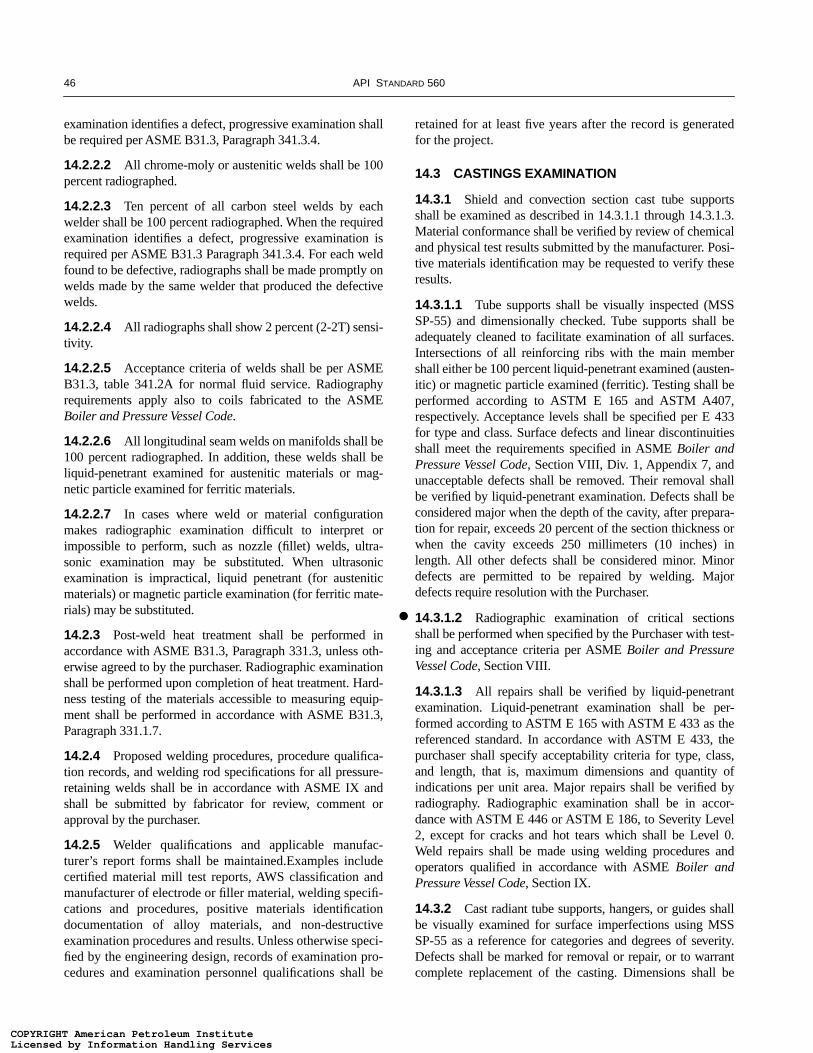
46 API STANDARD 560
examination identifies a defect, progressive examination shallbe required per ASME B31.3, Paragraph 341.3.4.
14.2.2.2 All chrome-moly or austenitic welds shall be 100percent radiographed.
14.2.2.3 Ten percent of all carbon steel welds by eachwelder shall be 100 percent radiographed. When the requiredexamination identifies a defect, progressive examination isrequired per ASME B31.3 Paragraph 341.3.4. For each weldfound to be defective, radiographs shall be made promptly onwelds made by the same welder that produced the defectivewelds.
14.2.2.4 All radiographs shall show 2 percent (2-2T) sensi-tivity.
14.2.2.5 Acceptance criteria of welds shall be per ASMEB31.3, table 341.2A for normal fluid service. Radiographyrequirements apply also to coils fabricated to the ASMEBoiler and Pressure Vessel Code.
14.2.2.6 All longitudinal seam welds on manifolds shall be100 percent radiographed. In addition, these welds shall beliquid-penetrant examined for austenitic materials or mag-netic particle examined for ferritic materials.
14.2.2.7 In cases where weld or material configurationmakes radiographic examination difficult to interpret orimpossible to perform, such as nozzle (fillet) welds, ultra-sonic examination may be substituted. When ultrasonicexamination is impractical, liquid penetrant (for austeniticmaterials) or magnetic particle examination (for ferritic mate-rials) may be substituted.
14.2.3 Post-weld heat treatment shall be performed inaccordance with ASME B31.3, Paragraph 331.3, unless oth-erwise agreed to by the purchaser. Radiographic examinationshall be performed upon completion of heat treatment. Hard-ness testing of the materials accessible to measuring equip-ment shall be performed in accordance with ASME B31.3,Paragraph 331.1.7.
14.2.4 Proposed welding procedures, procedure qualifica-tion records, and welding rod specifications for all pressure-retaining welds shall be in accordance with ASME IX andshall be submitted by fabricator for review, comment orapproval by the purchaser.
14.2.5 Welder qualifications and applicable manufac-turer’s report forms shall be maintained.Examples includecertified material mill test reports, AWS classification andmanufacturer of electrode or filler material, welding specifi-cations and procedures, positive materials identificationdocumentation of alloy materials, and non-destructiveexamination procedures and results. Unless otherwise speci-fied by the engineering design, records of examination pro-cedures and examination personnel qualifications shall be
retained for at least five years after the record is generatedfor the project.
14.3 CASTINGS EXAMINATION
14.3.1 Shield and convection section cast tube supportsshall be examined as described in 14.3.1.1 through 14.3.1.3.Material conformance shall be verified by review of chemicaland physical test results submitted by the manufacturer. Posi-tive materials identification may be requested to verify theseresults.
14.3.1.1 Tube supports shall be visually inspected (MSSSP-55) and dimensionally checked. Tube supports shall beadequately cleaned to facilitate examination of all surfaces.Intersections of all reinforcing ribs with the main membershall either be 100 percent liquid-penetrant examined (austen-itic) or magnetic particle examined (ferritic). Testing shall beperformed according to ASTM E 165 and ASTM A407,respectively. Acceptance levels shall be specified per E 433for type and class. Surface defects and linear discontinuitiesshall meet the requirements specified in ASME Boiler andPressure Vessel Code, Section VIII, Div. 1, Appendix 7, andunacceptable defects shall be removed. Their removal shallbe verified by liquid-penetrant examination. Defects shall beconsidered major when the depth of the cavity, after prepara-tion for repair, exceeds 20 percent of the section thickness orwhen the cavity exceeds 250 millimeters (10 inches) inlength. All other defects shall be considered minor. Minordefects are permitted to be repaired by welding. Majordefects require resolution with the Purchaser.
14.3.1.2 Radiographic examination of critical sectionsshall be performed when specified by the Purchaser with test-ing and acceptance criteria per ASME Boiler and PressureVessel Code, Section VIII.
14.3.1.3 All repairs shall be verified by liquid-penetrantexamination. Liquid-penetrant examination shall be per-formed according to ASTM E 165 with ASTM E 433 as thereferenced standard. In accordance with ASTM E 433, thepurchaser shall specify acceptability criteria for type, class,and length, that is, maximum dimensions and quantity ofindications per unit area. Major repairs shall be verified byradiography. Radiographic examination shall be in accor-dance with ASTM E 446 or ASTM E 186, to Severity Level2, except for cracks and hot tears which shall be Level 0.Weld repairs shall be made using welding procedures andoperators qualified in accordance with ASME Boiler andPressure Vessel Code, Section IX.
14.3.2 Cast radiant tube supports, hangers, or guides shallbe visually examined for surface imperfections using MSSSP-55 as a reference for categories and degrees of severity.Defects shall be marked for removal or repair, or to warrantcomplete replacement of the casting. Dimensions shall be
●
COPYRIGHT American Petroleum InstituteLicensed by Information Handling ServicesCOPYRIGHT American Petroleum InstituteLicensed by Information Handling Services
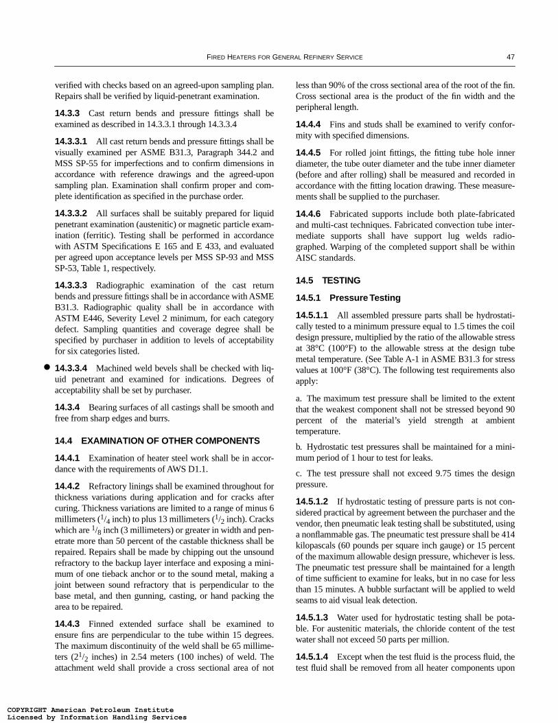
FIRED HEATERS FOR GENERAL REFINERY SERVICE 47
verified with checks based on an agreed-upon sampling plan.Repairs shall be verified by liquid-penetrant examination.
14.3.3 Cast return bends and pressure fittings shall beexamined as described in 14.3.3.1 through 14.3.3.4
14.3.3.1 All cast return bends and pressure fittings shall bevisually examined per ASME B31.3, Paragraph 344.2 andMSS SP-55 for imperfections and to confirm dimensions inaccordance with reference drawings and the agreed-uponsampling plan. Examination shall confirm proper and com-plete identification as specified in the purchase order.
14.3.3.2 All surfaces shall be suitably prepared for liquidpenetrant examination (austenitic) or magnetic particle exam-ination (ferritic). Testing shall be performed in accordancewith ASTM Specifications E 165 and E 433, and evaluatedper agreed upon acceptance levels per MSS SP-93 and MSSSP-53, Table 1, respectively.
14.3.3.3 Radiographic examination of the cast returnbends and pressure fittings shall be in accordance with ASMEB31.3. Radiographic quality shall be in accordance withASTM E446, Severity Level 2 minimum, for each categorydefect. Sampling quantities and coverage degree shall bespecified by purchaser in addition to levels of acceptabilityfor six categories listed.
14.3.3.4 Machined weld bevels shall be checked with liq-uid penetrant and examined for indications. Degrees ofacceptability shall be set by purchaser.
14.3.4 Bearing surfaces of all castings shall be smooth andfree from sharp edges and burrs.
14.4 EXAMINATION OF OTHER COMPONENTS
14.4.1 Examination of heater steel work shall be in accor-dance with the requirements of AWS D1.1.
14.4.2 Refractory linings shall be examined throughout forthickness variations during application and for cracks aftercuring. Thickness variations are limited to a range of minus 6millimeters (1/4 inch) to plus 13 millimeters (1/2 inch). Crackswhich are 1/8 inch (3 millimeters) or greater in width and pen-etrate more than 50 percent of the castable thickness shall berepaired. Repairs shall be made by chipping out the unsoundrefractory to the backup layer interface and exposing a mini-mum of one tieback anchor or to the sound metal, making ajoint between sound refractory that is perpendicular to thebase metal, and then gunning, casting, or hand packing thearea to be repaired.
14.4.3 Finned extended surface shall be examined toensure fins are perpendicular to the tube within 15 degrees.The maximum discontinuity of the weld shall be 65 millime-ters (21/2 inches) in 2.54 meters (100 inches) of weld. Theattachment weld shall provide a cross sectional area of not
less than 90% of the cross sectional area of the root of the fin.Cross sectional area is the product of the fin width and theperipheral length.
14.4.4 Fins and studs shall be examined to verify confor-mity with specified dimensions.
14.4.5 For rolled joint fittings, the fitting tube hole innerdiameter, the tube outer diameter and the tube inner diameter(before and after rolling) shall be measured and recorded inaccordance with the fitting location drawing. These measure-ments shall be supplied to the purchaser.
14.4.6 Fabricated supports include both plate-fabricatedand multi-cast techniques. Fabricated convection tube inter-mediate supports shall have support lug welds radio-graphed. Warping of the completed support shall be withinAISC standards.
14.5 TESTING
14.5.1 Pressure Testing
14.5.1.1 All assembled pressure parts shall be hydrostati-cally tested to a minimum pressure equal to 1.5 times the coildesign pressure, multiplied by the ratio of the allowable stressat 38°C (100°F) to the allowable stress at the design tubemetal temperature. (See Table A-1 in ASME B31.3 for stressvalues at 100°F (38°C). The following test requirements alsoapply:
a. The maximum test pressure shall be limited to the extentthat the weakest component shall not be stressed beyond 90percent of the material’s yield strength at ambienttemperature.
b. Hydrostatic test pressures shall be maintained for a mini-mum period of 1 hour to test for leaks.
c. The test pressure shall not exceed 9.75 times the designpressure.
14.5.1.2 If hydrostatic testing of pressure parts is not con-sidered practical by agreement between the purchaser and thevendor, then pneumatic leak testing shall be substituted, usinga nonflammable gas. The pneumatic test pressure shall be 414kilopascals (60 pounds per square inch gauge) or 15 percentof the maximum allowable design pressure, whichever is less.The pneumatic test pressure shall be maintained for a lengthof time sufficient to examine for leaks, but in no case for lessthan 15 minutes. A bubble surfactant will be applied to weldseams to aid visual leak detection.
14.5.1.3 Water used for hydrostatic testing shall be pota-ble. For austenitic materials, the chloride content of the testwater shall not exceed 50 parts per million.
14.5.1.4 Except when the test fluid is the process fluid, thetest fluid shall be removed from all heater components upon
●
COPYRIGHT American Petroleum InstituteLicensed by Information Handling ServicesCOPYRIGHT American Petroleum InstituteLicensed by Information Handling Services
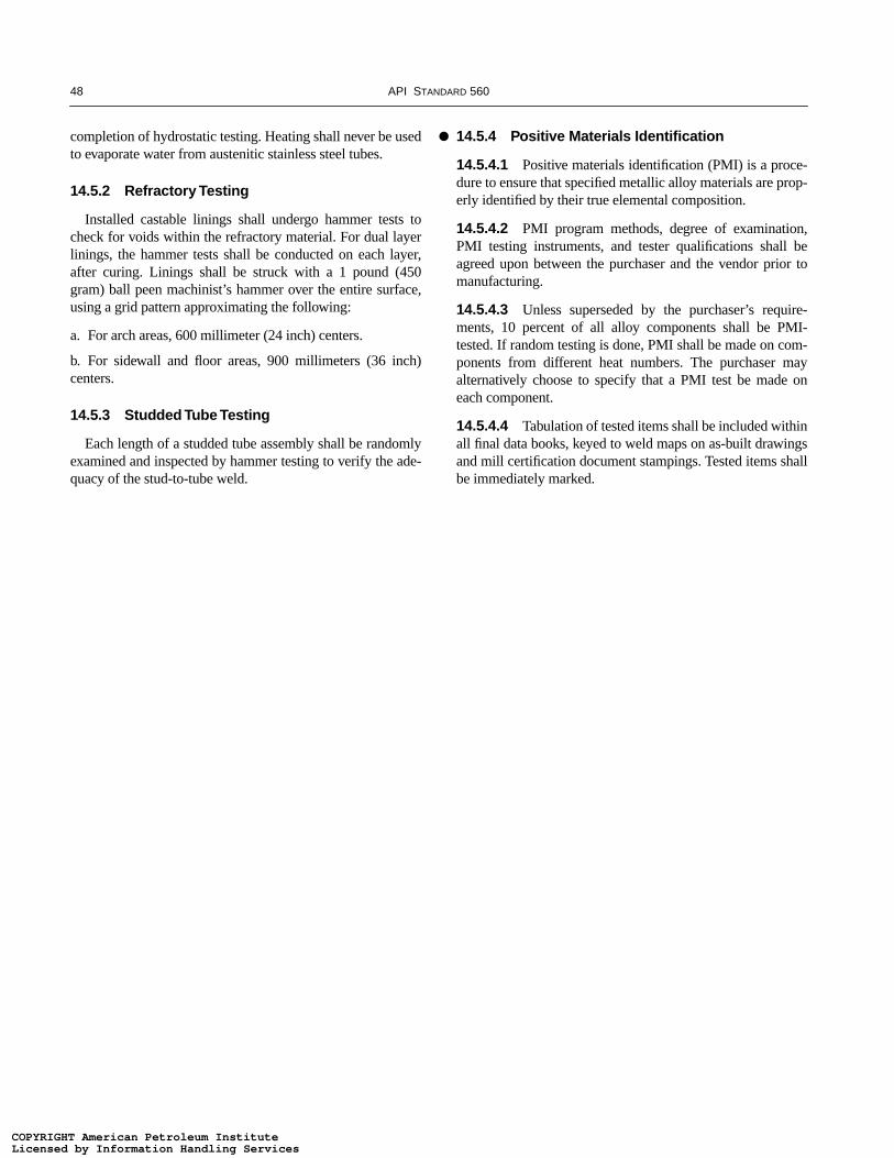
48 API STANDARD 560
completion of hydrostatic testing. Heating shall never be usedto evaporate water from austenitic stainless steel tubes.
14.5.2 Refractory Testing
Installed castable linings shall undergo hammer tests tocheck for voids within the refractory material. For dual layerlinings, the hammer tests shall be conducted on each layer,after curing. Linings shall be struck with a 1 pound (450gram) ball peen machinist’s hammer over the entire surface,using a grid pattern approximating the following:
a. For arch areas, 600 millimeter (24 inch) centers.
b. For sidewall and floor areas, 900 millimeters (36 inch)centers.
14.5.3 Studded Tube Testing
Each length of a studded tube assembly shall be randomlyexamined and inspected by hammer testing to verify the ade-quacy of the stud-to-tube weld.
14.5.4 Positive Materials Identification
14.5.4.1 Positive materials identification (PMI) is a proce-dure to ensure that specified metallic alloy materials are prop-erly identified by their true elemental composition.
14.5.4.2 PMI program methods, degree of examination,PMI testing instruments, and tester qualifications shall beagreed upon between the purchaser and the vendor prior tomanufacturing.
14.5.4.3 Unless superseded by the purchaser’s require-ments, 10 percent of all alloy components shall be PMI-tested. If random testing is done, PMI shall be made on com-ponents from different heat numbers. The purchaser mayalternatively choose to specify that a PMI test be made oneach component.
14.5.4.4 Tabulation of tested items shall be included withinall final data books, keyed to weld maps on as-built drawingsand mill certification document stampings. Tested items shallbe immediately marked.
●
COPYRIGHT American Petroleum InstituteLicensed by Information Handling ServicesCOPYRIGHT American Petroleum InstituteLicensed by Information Handling Services

49
APPENDIX A—EQUIPMENT DATA SHEETS
This appendix includes data sheets (customary and SI units) for the following equipmentitems:
a. Fired heater data sheets (6 sheets).
b. Burner data sheets (3 sheets).
c. Air preheater data sheets (2 sheets).
d. Fan data sheets (2 sheets).
e. Sootblower data sheets (1 sheet).
See 1.8 for instructions on using the equipment data sheets.
COPYRIGHT American Petroleum InstituteLicensed by Information Handling ServicesCOPYRIGHT American Petroleum InstituteLicensed by Information Handling Services

COPYRIGHT American Petroleum InstituteLicensed by Information Handling ServicesCOPYRIGHT American Petroleum InstituteLicensed by Information Handling Services

51
PURCHASER / OWNER : ITEM NO. :
SERVICE : LOCATION :1 * UNIT: *NUMBER REQUIRED: REV2 MANUFACTURER: REFERENCE:
3 TYPE OF HEATER:4 * TOTAL HEATER ABSORBED DUTY, MM Btu/hr. :
5 PROCESS DESIGN CONDITIONS6 * OPERATING CASE7 HEATER SECTION
8 * SERVICE
9 HEAT ABSORPTION, MM Btu/hr.
1 0 * FLUID1 1* FLOW RATE, Lb/hr.
1 2 * FLOW RATE, B.P.D.
1 3* PRESSURE DROP, ALLOWABLE (CLEAN / FOULED), Psi.
1 4 PRESSURE DROP, CALCULATED (CLEAN / FOULED), Psi.1 5 * AVG. RAD. SECT. FLUX DENSITY, ALLOWABLE, Btu/hr-ft 2.
1 6 AVG. RAD. SECT. FLUX DENSITY, CALCULATED, Btu/hr-ft 2.
1 7 MAX. RAD. SECT. FLUX DENSITY, Btu/hr-ft2.
1 8 CONV. SECT. FLUX DENSITY, (BARE TUBE), Btu/hr-ft2.1 9 * VELOCITY LIMITATION, ft/s.
2 0 PROCESS FLUID MASS VELOCITY, Lb/sec-ft2 .
2 1 * MAXIMUM ALLOW. / CALC. INSIDE FILM TEMPERATURE, oF.
2 2* FOULING FACTOR, hr-ft2 - o
F/Btu.2 3* COKING ALLOWANCE, in.
2 4 INLET CONDITIONS :2 5* TEMPERATURE, oF.
2 6* PRESSURE,
2 7* LIQUID FLOW, Lb/hr.2 8 * VAPOR FLOW, Lb/hr.
2 9 * LIQUID GRAVITY, (DEG API) (SP. GR @ 60oF.)
3 0* VAPOR MOLECULAR WEIGHT
3 1* VISCOSITY, (LIQUID / VAPOR), cP.
3 2* SPECIFIC HEAT, (LIQUID / VAPOR), Btu/Lb-oF.3 3* THERMAL CONDUCTIVITY, (LIQUID / VAPOR), Btu/hr-ft-oF.
3 4 OUTLET CONDITIONS :3 5* TEMPERATURE, oF.
3 6* PRESSURE,
3 7* LIQUID FLOW, Lb/hr.3 8 * VAPOR FLOW, Lb/hr.
3 9 * LIQUID GRAVITY, (DEG API) (SP. GR @ 60oF.)
4 0* VAPOR MOLECULAR WEIGHT
4 1* VISCOSITY, (LIQUID / VAPOR), cP.4 2* SPECIFIC HEAT, (LIQUID / VAPOR), Btu/Lb-oF.4 3* THERMAL CONDUCTIVITY, (LIQUID / VAPOR), Btu/hr-ft-oF.
4 4 REMARKS AND SPECIAL REQUIREMENTS :4 5* DISTILLATION DATA OR FEED COMPOSITION:
4 6* SHORT TERM OPERATING CONDITIONS:4 7
4 8 NOTES:
4 9
5 05 1
5 2
5 3
5 45 5
5 6
5 75 8
PROJECT NUMBER DOCUMENT NUMBER REV
CUSTOMARY UNITS
1 OF 6
SHEET
(Psig) (Psia)
(Psig) (Psia)
FIRED HEATER DATA SHEETAPI STANDARD 560
COPYRIGHT American Petroleum InstituteLicensed by Information Handling ServicesCOPYRIGHT American Petroleum InstituteLicensed by Information Handling Services

52
COMBUSTION DESIGN CONDITIONS1 * OPERATING CASE REV2 * TYPE OF FUEL
3 * EXCESS AIR, %
4 CALCULATED HEAT RELEASE (LHV), MM Btu/hr.5 FUEL EFFICIENCY CALCULATED, % (LHV).
6 * FUEL EFFICIENCY GUARANTEED, % (LHV).
7 RADIANTION LOSS, PERCENT OF HEAT RELEASE (LHV).8 FLUE GAS TEMPERATURE LEAVING: RADIANT SECTION, oF.
9 CONVECTION SECTION, oF.
1 0 AIR PREHEATER, oF.
1 1 FLUE GAS QUANTITY, Lb/hr.1 2 FLUE GAS MASS VELOCITY THRU. CONVECTION SECTION, Lb/sec-ft2.
1 3 DRAFT: AT ARCH, in H2O.
1 4 AT BURNERS, in H2O.
1 5 AMBIENT AIR TEMPERATURE, EFFICIENCY CALCULATION, oF.1 6 * AMBIENT AIR TEMPERATURE, STACK DESIGN, oF.
1 7 * ALTITUDE ABOVE SEA LEVEL, ft.1 8 VOLUMETRIC HEAT RELEASE (LHV), Btu/hr-ft3.
1 9 FUEL CHARACTERISTICS2 0 * GAS TYPE: * LIQUID TYPE: 8 OTHER TYPE:2 1 * LHV, * LHV, Btu/Lb. * LHV,
2 2 * HHV, * HHV, Btu/Lb. * HHV,
2 3 * PRESS. @ BURNER, Psig. * PRESS. @ BURNER, Psig. * PRESS. @ BURNER, Psig.
2 4 * TEMP. @ BURNER,oF. * TEMP. @ BURNER,
oF. * TEMP. @ BURNER,oF.
2 5 * MOLECULAR WEIGHT * VISCOSITY @ oF. SSU. * MOLECULAR WEIGHT
2 6 * ATOMIZING STEAM TEMP., oF.
2 7 * * ATOMIZING STEAM PRESSURE, Psig.
2 82 9 * COMPOSITION WT%
3 0
3 1
3 23 3
3 4 * VANADIUM (PPM)
3 5 * SODIUM (PPM)
3 6 * SULFUR3 7 * ASH
3 8 BURNER DATA3 9 MANUFACTURER: SIZE / MODEL: NUMBER:
4 0 * TYPE: LOCATION: ORIENTATION:
4 1 HEAT RELEASE PER BURNER, MM Btu/hr. DESIGN: NORMAL: MINIMUM:4 2 PRESSURE DROP ACROSS BURNER @ DESIGN HEAT RELEASE, in H2O:
4 3 DISTANCE BURNER CENTER LINE TO TUBE CENTER LINE, ft. HORIZONTAL: VERTICAL:
4 4 DISTANCE BURNER CENTER LINE TO UNSHIELDED REFRACTORY, ft. HORIZONTAL: VERTICAL:
4 5 * PILOT, TYPE: CAPACITY, Btu/hr:4 6 * IGNITION METHOD:4 7 * FLAME SCANNERS, LOCATION: NUMBER:
4 8 REQUIRED EMMISIONS: ppmv(d) (CORRECTED TO 3% O2) NOx: CO: SOx:4 9 Lb/ MM Btu UHC: PARTICULATES:
5 0 NOTES:
5 1
5 2
5 35 4
5 5
5 6
5 75 8
5 96 0
PROJECT NUMBER DOCUMENT NUMBER SHEET REV
(LHV) (HHV)
2 OF 6
CUSTOMARY UNITS
Btu/(Lb) (scf).
* COMPOSITION
Btu/(Lb) (scf).Btu/(Lb) (Scf).
MOLE %MOLE %
Btu/(Lb) (Scf).
COMPOSITION
FIRED HEATER DATA SHEETAPI STANDARD 560
COPYRIGHT American Petroleum InstituteLicensed by Information Handling ServicesCOPYRIGHT American Petroleum InstituteLicensed by Information Handling Services
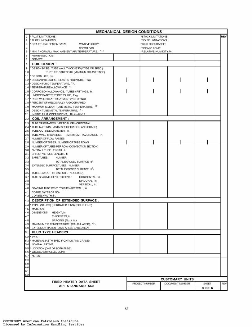
53
MECHANICAL DESIGN CONDITIONS1 * PLOT LIMITATIONS: *STACK LIMITATIONS: REV2 * TUBE LIMITATIONS: *NOISE LIMITATIONS:3 * STRUCTURAL DESIGN DATA: WIND VELOCITY: *WIND OCCURANCE:
4 SNOW LOAD: *SEISMIC ZONE:5 * MIN. / NORMAL / MAX. AMBIENT AIR TEMPERATURE, oF.: *RELATIVE HUMIDITY,%:
6 HEATER SECTION :7 SERVICE :
8 COIL DESIGN :9 * DESIGN BASIS: TUBE WALL THICKNESS (CODE OR SPEC.)
1 0 RUPTURE STRENGTH (MINIMUM OR AVERAGE)
1 1 * DESIGN LIFE, hr.1 2 * DESIGN PRESSURE, ELASTIC / RUPTURE, Psig.1 3 * DESIGN FLUID TEMPERATURE, oF.1 4 * TEMPERATURE ALLOWANCE, oF.
1 5 * CORROSION ALLOWANCE, TUBES / FITTINGS, in.1 6 HYDROSTATIC TEST PRESSURE, Psig.1 7 * POST WELD HEAT TREATMENT (YES OR NO)1 8 * PERCENT OF WELDS FULLY RADIOGRAPHED
1 9 MAXIMUM (CLEAN) TUBE METAL TEMPERATURE, oF.
2 0 DESIGN TUBE METAL TEMPERATURE, oF.
2 1 INSIDE FILM COEFFICIENT, Btu/hr-ft2 -oF .
2 2 COIL ARRANGEMENT :2 3 TUBE ORIENTATION: VERTICAL OR HORIZONTAL2 4 * TUBE MATERIAL (ASTM SPECIFICATION AND GRADE)2 5 TUBE OUTSIDE DIAMETER, in.
2 6 TUBE WALL THICKNESS, in.2 7 NUMBER OF FLOW PASSES2 8 NUMBER OF TUBES / NUMBER OF TUBE ROWS
2 9 NUMBER OF TUBES PER ROW (CONVECTION SECTION)3 0 OVERALL TUBE LENGTH, ft.3 1 EFFECTIVE TUBE LENGTH, ft.3 2 BARE TUBES: NUMBER
3 3 TOTAL EXPOSED SURFACE, ft2.
3 4 EXTENDED SURFACE TUBES: NUMBER3 5 TOTAL EXPOSED SURFACE, ft2.
3 6 TUBES LAYOUT (IN LINE OR STAGGERED)
3 7 TUBE SPACING, CENT. TO CENT. : HORIZONTAL, in.3 8 DIAGONAL, in.3 9 VERTICAL, in.4 0 SPACING TUBE CENT. TO FURNACE WALL, in.
4 1 CORBELS (YES OR NO)4 2 CORBEL WIDTH, in.
4 3 DESCRIPTION OF EXTENDED SURFACE :4 4 * TYPE: (STUDS) (SERRATED FINS) (SOLID FINS)4 5 MATERIAL4 6 DIMENSIONS:4 7
4 8 SPACING (No. / in.)4 9 MAXIMUM TIP TEMPERATURE, (CALCULATED), oF.
5 0 EXTENSION RATIO (TOTAL AREA / BARE AREA)
5 1 PLUG TYPE HEADERS :5 2 * TYPE5 3 * MATERIAL (ASTM SPECIFICATION AND GRADE)5 4 NOMINAL RATING
5 5 * LOCATION (ONE OR BOTH ENDS)5 6 * WELDED OR ROLLED JOINT
5 7 NOTES:5 8
5 96 06 16 2
REVSHEET
3 OF 6
PROJECT NUMBER DOCUMENT NUMBER
CUSTOMARY UNITS
HEIGHT, in.
(MINIMUM) (AVERAGE),
THICKNESS, in.
FIRED HEATER DATA SHEETAPI STANDARD 560
COPYRIGHT American Petroleum InstituteLicensed by Information Handling ServicesCOPYRIGHT American Petroleum InstituteLicensed by Information Handling Services

54
MECHANICAL DESIGN CONDITIONS (Cont'd)
1 HEATER SECTION REV2 SERVICE
3 RETURN BENDS :4 TYPE
5 * MATERIAL (ASTM SPECIFICATION AND GRADE)
6 NOMINAL RATING OR SCHEDULE7 LOCATION (F. B. = FIRE BOX, H. B. = HEADER BOX)
8 TERMINALS AND OR MANIFOLDS :9 * TYPE (BEV. = BEVELED, MAN. = MANIFOLD, FLG. = FLANGED)
1 0 * INLET: MATERIAL (ASTM SPECIFICATION AND GRADE)
1 1 SIZE
1 2 SCHEDULE OR THICKNESS1 3 NUMBER OF TERMINALS
1 4 FLANGE MATERIAL (ASTM SPEC. AND GRADE)
1 5 FLANGE SIZE AND RATING
1 6 * OUTLET: MATERIAL (ASTM SPECIFICATION AND GRADE)1 7 SIZE
1 8 SCHEDULE OR THICKNESS
1 9 NUMBER OF TERMINALS
2 0 FLANGE MATERIAL (ASTM SPEC. AND GRADE)
2 1 FLANGE SIZE AND RATING2 2 * MANIFOLD TO TUBE CONN. (WELDED, EXTRUDED, ETC.)2 3 MANIFOLD LOCATION (INSIDE OR OUTSIDE HEADER BOX)
2 4 CROSSOVERS :2 5 * WELDED OR FLANGED
2 6 * PIPE MATERIAL (ASTM SPECIFICATION AND GRADE)2 7 PIPE SIZE
2 8 PIPE SCHEDULE OR THICKNESS
2 9 * FLANGE MATERIAL
3 0 FLANGE SIZE / RATING3 1 * LOCATION (INTERNAL / EXTERNAL)3 2 FLUID TEMPERATURE, oF.
3 3 TUBE SUPPORTS :3 4 LOCATION (ENDS, TOP, BOTTOM)
3 5 MATERIAL (ASTM SPECIFICATION AND GRADE)3 6 DESIGN METAL TEMPERATURE, oF.
3 7 THICKNESS, in.
3 8 INSULATION: THICKNESS, in.
3 9 MATERIAL4 0 ANCHOR (MATERIAL AND TYPE)
4 1 INTERMEDIATE TUBE SUPPORTS :4 2 * MATERIAL (ASTM SPECIFICATION AND GRADE)
4 3 DESIGN METAL TEMPERATURE, oF.
4 4 THICKNESS, in.4 5 SPACING, ft.
4 6 TUBE GUIDES :4 7 LOCATION
4 8 * MATERIAL4 9 TYPE / SPACING
5 0 HEADER BOXES :5 1 LOCATION: HINGED DOOR / BOLTED PANEL:
5 2 CASING MATERIAL : THICKNESS, in.:
5 3 LINING MATERIAL: THICKNESS, in.: 5 4 ANCHOR (MATERIAL AND TYPE):
5 5 NOTES :
5 6
5 75 8
PROJECT NUMBER DOCUMENT NUMBER SHEET REV
4 OF 6
CUSTOMARY UNITSFIRED HEATER DATA SHEET
API STANDARD 560
COPYRIGHT American Petroleum InstituteLicensed by Information Handling ServicesCOPYRIGHT American Petroleum InstituteLicensed by Information Handling Services

55
MECHANICAL DESIGN CONDITIONS (Cont'd)1 REFRACTORY DESIGN BASIS : REV2 * AMBIENT, oF.: WIND VELOCITY, mph.: CASING TEMP., oF.:
3 EXPOSED VERTICAL WALLS :
4 LINING THICKNESS, in.: HOT FACE TEMPERATURE, SERVICE, oF.: CALCULATED, oF:
5 WALL CONSTRUCTION:
6
7 ANCHOR (MATERIAL & TYPE):8 CASING MATERIAL: THICKNESS, in.: TEMPERATURE, oF.:
9 SHIELDED VERTICAL WALLS :
1 0 LINING THICKNESS, in.: HOT FACE TEMPERATURE, SERVICE, oF.: CALCULATED, oF.:
1 1 WALL CONSTRUCTION:1 2
1 3 ANCHOR (MATERIAL & TYPE):1 4 CASING MATERIAL: THICKNESS, in.: TEMPERATURE,
oF.:
1 5 ARCH :
1 6 LINING THICKNESS, in.: HOT FACE TEMPERATURE, SERVICE, oF.: CALCULATED,
oF.:
1 7 WALL CONSTRUCTION:
1 8
1 9 ANCHOR (MATERIAL & TYPE):2 0 CASING MATERIAL: THICKNESS, in.: TEMPERATURE, oF.:
2 1 FLOOR :
2 2 LINING THICKNESS, in.: HOT FACE TEMPERATURE, SERVICE, oF.: CALCULATED, oF.:
2 3 FLOOR CONSTRUCTION:
2 4
2 5 CASING MATERIAL: THICKNESS , in.: TEMPERATURE, oF.:2 6 * MINIMUM FLOOR ELEVATION, ft.: FREE SPACE BELOW PLENUM, ft.:
2 7 CONVECTION SECTION :2 8 LINING THICKNESS, in.: HOT FACE TEMPERATURE, SERVICE, oF.: CALCULATED, oF.:
2 9 WALL CONSTRUCTION:3 0
3 1 ANCHOR (MATERIAL & TYPE):3 2 CASING MATERIAL: THICKNESS, in.: TEMPERATURE,
oF.:
3 3 INTERNAL WALL :3 4 TYPE: MATERIAL:3 5 DIMENSION, HEIGHT / WIDTH, ft.:
3 6 DUCTS :3 7 LOCATION
3 8 SIZE, ft. OR NET FREE AREA, ft2.
3 9 CASING MATERIAL4 0 CASING THICKNESS, in.
4 1 LINING: INTERNAL / EXTERNAL
4 2 THICKNESS, in.
4 3 MATERIAL 4 4 ANCHOR (MATERIAL & TYPE)4 5 CASING TEMPERATURE, oF.
4 6 PLENUM CHAMBER (AIR) :4 7 TYPE OF PLENUM (COMMON OR INTEGRAL):4 8 CASING MATERIAL: THICKNESS, in.: SIZE, in.:
4 9 LINING MATERIAL: THICKNESS, in.:5 0 ANCHOR (MATERIAL & TYPE):
5 1 NOTES :5 2
53
54
5556
5758
REV
BREECHINGFLUE GAS COMBUSTION AIR
5 OF 6
PROJECT NUMBER DOCUMENT NUMBER SHEET
CUSTOMARY UNITSFIRED HEATER DATA SHEET
API STANDARD 560
COPYRIGHT American Petroleum InstituteLicensed by Information Handling ServicesCOPYRIGHT American Petroleum InstituteLicensed by Information Handling Services
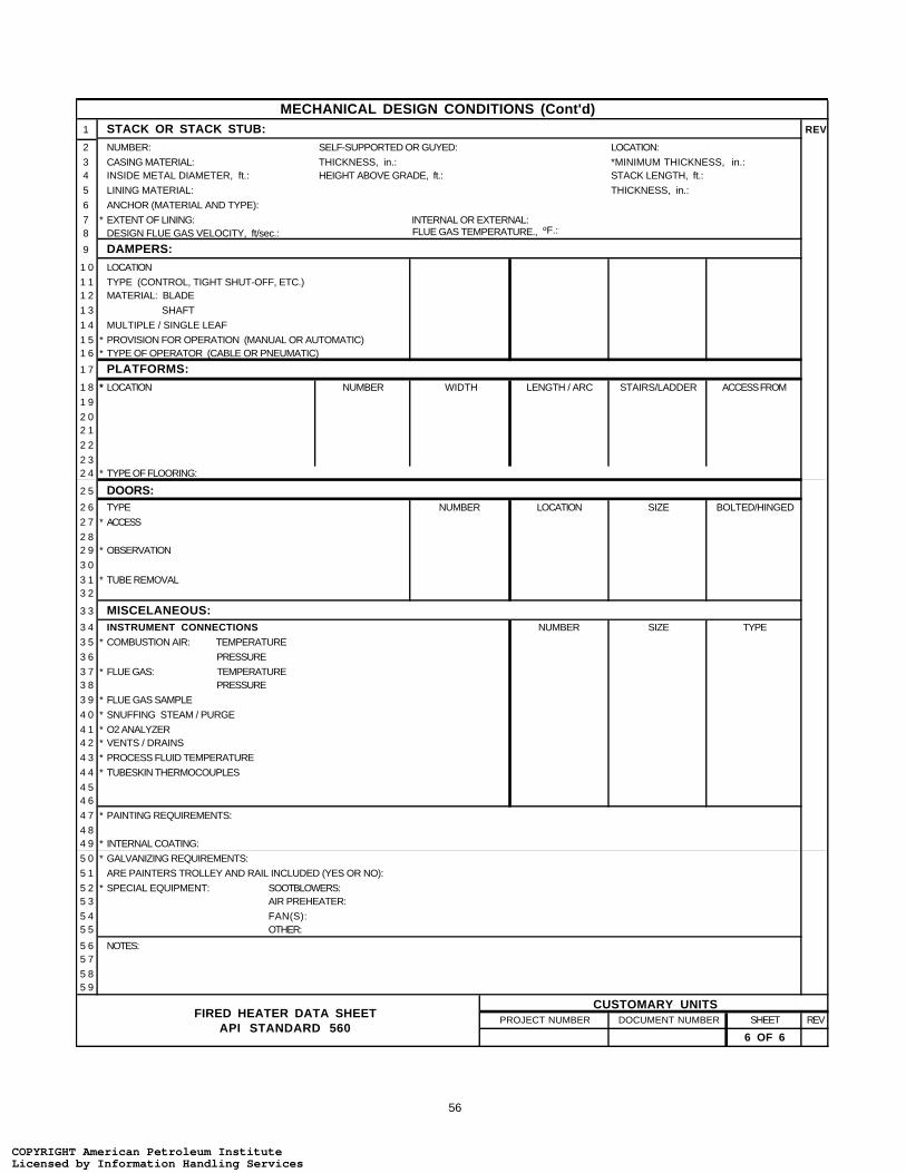
56
MECHANICAL DESIGN CONDITIONS (Cont'd) 1 STACK OR STACK STUB: REV
2 NUMBER: SELF-SUPPORTED OR GUYED: LOCATION:
3 CASING MATERIAL: THICKNESS, in.: *MINIMUM THICKNESS, in.: 4 INSIDE METAL DIAMETER, ft.: HEIGHT ABOVE GRADE, ft.: STACK LENGTH, ft.:
5 LINING MATERIAL: THICKNESS, in.:
6 ANCHOR (MATERIAL AND TYPE):
7 * EXTENT OF LINING: INTERNAL OR EXTERNAL:8 DESIGN FLUE GAS VELOCITY, ft/sec.: FLUE GAS TEMPERATURE., oF.:
9 DAMPERS:1 0 LOCATION
1 1 TYPE (CONTROL, TIGHT SHUT-OFF, ETC.)1 2 MATERIAL: BLADE
1 3 SHAFT
1 4 MULTIPLE / SINGLE LEAF
1 5 * PROVISION FOR OPERATION (MANUAL OR AUTOMATIC)1 6 * TYPE OF OPERATOR (CABLE OR PNEUMATIC)
1 7 PLATFORMS:1 8 * LOCATION NUMBER
1 9
2 02 1
2 2
2 32 4 * TYPE OF FLOORING:
2 5 DOORS:2 6 TYPE
2 7 *
2 82 9 *
3 0
3 1 *3 2
3 3 MISCELANEOUS:3 4 INSTRUMENT CONNECTIONS3 5 * COMBUSTION AIR: TEMPERATURE
3 6 PRESSURE
3 7 * FLUE GAS: TEMPERATURE3 8 PRESSURE
3 9 * FLUE GAS SAMPLE
4 0 * SNUFFING STEAM / PURGE
4 1 * O2 ANALYZER4 2 * VENTS / DRAINS
4 3 * PROCESS FLUID TEMPERATURE
4 4 * TUBESKIN THERMOCOUPLES
4 54 6
4 7 * PAINTING REQUIREMENTS:
4 84 9 * INTERNAL COATING:
5 0 * GALVANIZING REQUIREMENTS:
5 1 ARE PAINTERS TROLLEY AND RAIL INCLUDED (YES OR NO):
5 2 * SPECIAL EQUIPMENT: SOOTBLOWERS:5 3 AIR PREHEATER:
5 4 FAN(S):5 5 OTHER:
5 6 NOTES:5 7
5 85 9
REVDOCUMENT NUMBER SHEET
CUSTOMARY UNITS
WIDTH LENGTH / ARC STAIRS/LADDER ACCESS FROM
NUMBER LOCATION SIZE BOLTED/HINGED
ACCESS
OBSERVATION
TUBE REMOVAL
NUMBER SIZE TYPE
6 OF 6
PROJECT NUMBERFIRED HEATER DATA SHEET
API STANDARD 560
COPYRIGHT American Petroleum InstituteLicensed by Information Handling ServicesCOPYRIGHT American Petroleum InstituteLicensed by Information Handling Services
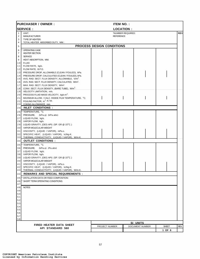
57
PURCHASER / OWNER : ITEM NO. :
SERVICE : LOCATION :1 * UNIT: *NUMBER REQUIRED: REV2 MANUFACTURER: REFERENCE:
3 TYPE OF HEATER:4 * TOTAL HEATER ABSORBED DUTY, MW. :
5 PROCESS DESIGN CONDITIONS6 * OPERATING CASE7 HEATER SECTION
8 * SERVICE
9 HEAT ABSORPTION, MW.
1 0* FLUID1 1* FLOW RATE, kg/s.
1 2* FLOW RATE, B.P.D.
1 3* PRESSURE DROP, ALLOWABLE (CLEAN / FOULED), kPa.
1 4 PRESSURE DROP, CALCULATED (CLEAN / FOULED), kPa.1 5* AVG. RAD. SECT. FLUX DENSITY, ALLOWABLE, \\//m2.
1 6 AVG. RAD. SECT. FLUX DENSITY, CALCULATED, W/m2.
1 7 MAX. RAD. SECT. FLUX DENSITY, W/m2.
1 8 CONV. SECT. FLUX DENSITY, (BARE TUBE), W/m2.
1 9* VELOCITY LIMITATION, m/s.
2 0 PROCESS FLUID MASS VELOCITY, kg/s-m2.
2 1* MAXIMUM ALLOW. / CALC. INSIDE FILM TEMPERATURE, oC.
2 2* FOULING FACTOR, m2- K / W .
2 3* COKING ALLOWANCE, mm.
2 4 INLET CONDITIONS :2 5 * TEMPERATURE, oC.
2 6* PRESSURE,
2 7* LIQUID FLOW, kg/s.2 8* VAPOR FLOW, kg/s.
2 9* LIQUID GRAVITY, (DEG API) (SP. GR @ 15oC.)
3 0* VAPOR MOLECULAR WEIGHT
3 1* VISCOSITY, (LIQUID / VAPOR), mPa.s.
3 2* SPECIFIC HEAT, (LIQUID / VAPOR), kJ/kg-K.3 3* THERMAL CONDUCTIVITY, (LIQUID / VAPOR), W/m-K.
3 4 OUTLET CONDITIONS :3 5 * TEMPERATURE, oC.
3 6* PRESSURE,
3 7* LIQUID FLOW, kg/s.3 8* VAPOR FLOW, kg/s.
3 9* LIQUID GRAVITY, (DEG API) (SP. GR @ 15oC.)
4 0* VAPOR MOLECULAR WEIGHT
4 1* VISCOSITY, (LIQUID / VAPOR), mPa.s.4 2* SPECIFIC HEAT, (LIQUID / VAPOR), kJ/kg-K.4 3* THERMAL CONDUCTIVITY, (LIQUID / VAPOR), W/m-K.
4 4 REMARKS AND SPECIAL REQUIREMENTS :4 5 * DISTILLATION DATA OR FEED COMPOSITION:
4 6 * SHORT TERM OPERATING CONDITIONS:4 7
4 8 NOTES:
4 9
5 05 1
5 2
5 3
5 45 5
5 6
5 75 8
PROJECT NUMBER DOCUMENT NUMBER REV
SI UNITS
1 OF 6
SHEET
(kPa.g) (kPa.abs)
(kPa.g) (Pa.abs)
FIRED HEATER DATA SHEETAPI STANDARD 560
COPYRIGHT American Petroleum InstituteLicensed by Information Handling ServicesCOPYRIGHT American Petroleum InstituteLicensed by Information Handling Services

58
COMBUSTION DESIGN CONDITIONS1 OPERATING CASE REV2 * TYPE OF FUEL
3 * EXCESS AIR, %
4 CALCULATED HEAT RELEASE (LHV), MW.5 FUEL EFFICIENCY CALCULATED, % (LHV).
6 * FUEL EFFICIENCY GUARANTEED, % (LHV).
7 RADIANTION LOSS, PERCENT OF HEAT RELEASE (LHV).8 FLUE GAS TEMPERATURE LEAVING: RADIANT SECTION, oC.
9 CONVECTION SECTION, oC.
1 0 AIR PREHEATER, oC.
1 1 FLUE GAS QUANTITY, kg/s.1 2 FLUE GAS MASS VELOCITY THRU. CONVECTION SECTION, kg/s-m2.
1 3 DRAFT: AT ARCH, Pa.
1 4 AT BURNERS, Pa.
1 5 * AMBIENT AIR TEMPERATURE, EFFICIENCY CALCULATION, oC.1 6 * AMBIENT AIR TEMPERATURE, STACK DESIGN, oC.
1 7 * ALTITUDE ABOVE SEA LEVEL, mm.1 8 VOLUMETRIC HEAT RELEASE (LHV), kW/m3.
1 9 FUEL CHARACTERISTICS2 0 * GAS TYPE: * LIQUID TYPE: *OTHER TYPE:2 1 * LHV, * LHV, kJ/kg. * LHV,
2 2 * HHV, * HHV, kJ/kg. * HHV,
2 3 * PRESS. @ BURNER, kPa.g. * PRESS @ BURNER, kPa.g. * PRESS. @ BURNER, kPa.g.
2 4 * TEMP. @ BURNER,oC. * TEMP. @ BURNER,
oC. * TEMP. @ BURNER,oC.
2 5 * MOLECULAR WEIGHT * VISCOSITY @ oC. SSU. * MOLECULAR WEIGHT
2 6 * ATOMIZING STEAM TEMP., oC.
2 7 * * ATOMIZING STEAM PRESSURE, kPa.g.
2 82 9 * COMPOSITION WT%
3 0
3 1
3 23 3
3 4 * VANADIUM (PPM)
3 5 * SODIUM (PPM)
3 6 * SULFUR3 7 * ASH
3 8 BURNER DATA3 9 MANUFACTURER: SIZE / MODEL: NUMBER:
4 0 * TYPE: LOCATION: ORIENTATION:
4 1 HEAT RELEASE PER BURNER, MW. DESIGN: NORMAL: MINIMUM:4 2 PRESSURE DROP ACROSS BURNER @ DESIGN HEAT RELEASE, Pa.:
4 3 DISTANCE BURNER CENTER LINE TO TUBE CENTER LINE, mm. HORIZONTAL: VERTICAL:
4 4 DISTANCE BURNER CENTER LINE TO UNSHIELDED REFRACTORY, mm. HORIZONTAL: VERTICAL:
4 5 * PILOT, TYPE: CAPACITY, kW:4 6 * IGNITION METHOD:4 7 * FLAME SCANNERS, LOCATION: NUMBER:
4 8 REQUIRED EMMISIONS: ppmv(d) (CORRECTED TO 3% O2) NOx: CO: SOx:4 9 kg/ kJ UHC: PARTICULATES:
5 0 NOTES:
5 1
5 2
5 35 4
5 5
5 6
5 75 8
5 96 0
PROJECT NUMBER DOCUMENT NUMBER SHEET REV
SI UNITS
2 OF 6
kJ/(kg) (Nm3 ) .
* COMPOSITION
kJ/(kg) (Nm3 ) .kJ/(kg) (Nm3 ) .
MOLE %MOLE %
kJ/(kg) (Nm3 ) .
COMPOSITION
(LHV) (HHV)
FIRED HEATER DATA SHEETAPI STANDARD 560
COPYRIGHT American Petroleum InstituteLicensed by Information Handling ServicesCOPYRIGHT American Petroleum InstituteLicensed by Information Handling Services
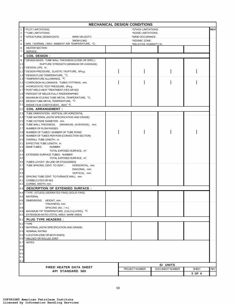
59
MECHANICAL DESIGN CONDITIONS1 * PLOT LIMITATIONS: *STACK LIMITATIONS: REV2 * TUBE LIMITATIONS: *NOISE LIMITATIONS:
3 * STRUCTURAL DESIGN DATA: WIND VELOCITY: *WIND OCCURANCE:
4 SNOW LOAD: *SEISMIC ZONE:5 * MIN. / NORMAL / MAX. AMBIENT AIR TEMPERATURE, oC.: *RELATIVE HUMIDITY,%:
6 HEATER SECTION :7 SERVICE :
8 COIL DESIGN :9 * DESIGN BASIS: TUBE WALL THICKNESS (CODE OR SPEC.)
1 0 RUPTURE STRENGTH (MINIMUM OR AVERAGE)1 1 * DESIGN LIFE, hr.
1 2 * DESIGN PRESSURE, ELASTIC / RUPTURE, kPa.g.
1 3 * DESIGN FLUID TEMPERATURE, oC.
1 4 * TEMPERATURE ALLOWANCE, oC.
1 5 * CORROSION ALLOWANCE, TUBES / FITTINGS, mm.
1 6 HYDROSTATIC TEST PRESSURE, kPa.g.1 7 * POST WELD HEAT TREATMENT (YES OR NO)
1 8 * PERCENT OF WELDS FULLY RADIOGRAPHED
1 9 MAXIMUM (CLEAN) TUBE METAL TEMPERATURE, oC.2 0 DESIGN TUBE METAL TEMPERATURE, oC.
2 1 INSIDE FILM COEFFICIENT, W/m2- K .
2 2 COIL ARRANGEMENT :2 3 TUBE ORIENTATION: VERTICAL OR HORIZONTAL
2 4 * TUBE MATERIAL (ASTM SPECIFICATION AND GRADE)
2 5 TUBE OUTSIDE DIAMETER, mm.2 6 TUBE WALL THICKNESS, mm.
2 7 NUMBER OF FLOW PASSES
2 8 NUMBER OF TUBES / NUMBER OF TUBE ROWS2 9 NUMBER OF TUBES PER ROW (CONVECTION SECTION)
3 0 OVERALL TUBE LENGTH, m.
3 1 EFFECTIVE TUBE LENGTH, m.3 2 BARE TUBES: NUMBER
3 3 TOTAL EXPOSED SURFACE, m2.
3 4 EXTENDED SURFACE TUBES: NUMBER3 5 TOTAL EXPOSED SURFACE, m2.
3 6 TUBES LAYOUT (IN LINE OR STAGGERED)3 7 TUBE SPACING, CENT. TO CENT. : HORIZONTAL, mm.
3 8 DIAGONAL, mm.
3 9 VERTICAL, mm.4 0 SPACING TUBE CENT. TO FURNACE WALL, mm.
4 1 CORBELS (YES OR NO)4 2 CORBEL WIDTH, mm.
4 3 DESCRIPTION OF EXTENDED SURFACE :4 4 * TYPE: (STUDS) (SERRATED FINS) (SOLID FINS)
4 5 MATERIAL
4 6 DIMENSIONS:4 7
4 8 SPACING (No. / m.)4 9 MAXIMUM TIP TEMPERATURE, (CALCULATED), oC.
5 0 EXTENSION RATIO (TOTAL AREA / BARE AREA)
5 1 PLUG TYPE HEADERS :5 2 * TYPE5 3 * MATERIAL (ASTM SPECIFICATION AND GRADE)
5 4 NOMINAL RATING
5 5 * LOCATION (ONE OR BOTH ENDS)5 6 * WELDED OR ROLLED JOINT
5 7 NOTES:
5 85 9
6 06 1
6 2
REVSHEET
3 OF 6
PROJECT NUMBER DOCUMENT NUMBER
SI UNITS
HEIGHT, mm.
(MINIMUM) (AVERAGE),
THICKNESS, mm.
FIRED HEATER DATA SHEETAPI STANDARD 560
COPYRIGHT American Petroleum InstituteLicensed by Information Handling ServicesCOPYRIGHT American Petroleum InstituteLicensed by Information Handling Services
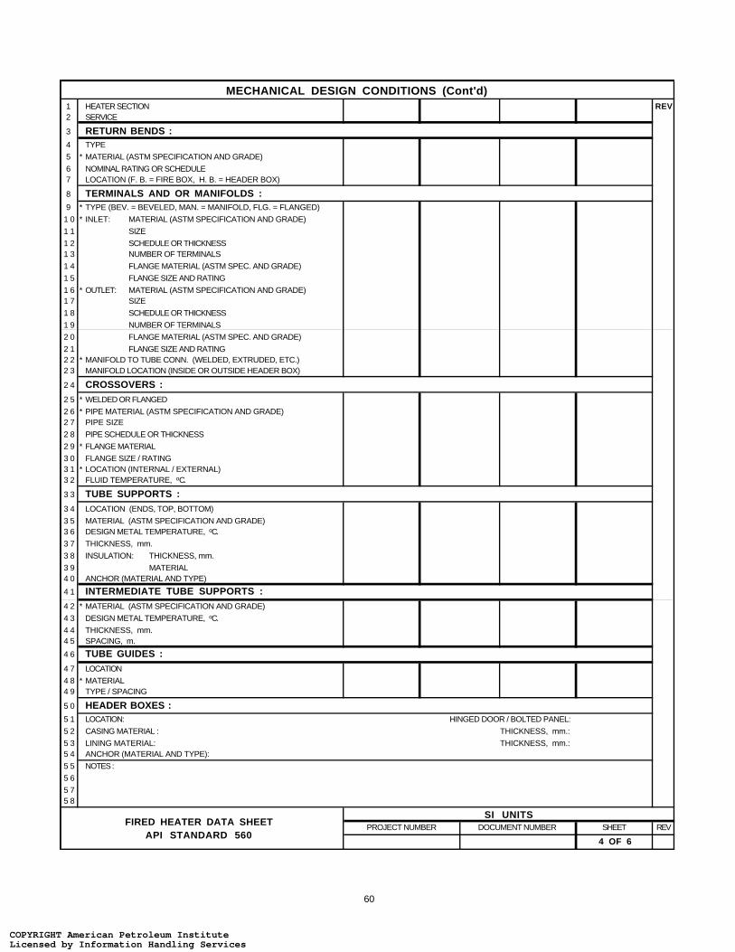
60
MECHANICAL DESIGN CONDITIONS (Cont'd)
1 HEATER SECTION REV2 SERVICE
3 RETURN BENDS :4 TYPE
5 * MATERIAL (ASTM SPECIFICATION AND GRADE)
6 NOMINAL RATING OR SCHEDULE7 LOCATION (F. B. = FIRE BOX, H. B. = HEADER BOX)
8 TERMINALS AND OR MANIFOLDS :9 * TYPE (BEV. = BEVELED, MAN. = MANIFOLD, FLG. = FLANGED)
1 0 * INLET: MATERIAL (ASTM SPECIFICATION AND GRADE)
1 1 SIZE
1 2 SCHEDULE OR THICKNESS1 3 NUMBER OF TERMINALS
1 4 FLANGE MATERIAL (ASTM SPEC. AND GRADE)
1 5 FLANGE SIZE AND RATING
1 6 * OUTLET: MATERIAL (ASTM SPECIFICATION AND GRADE)1 7 SIZE
1 8 SCHEDULE OR THICKNESS
1 9 NUMBER OF TERMINALS
2 0 FLANGE MATERIAL (ASTM SPEC. AND GRADE)
2 1 FLANGE SIZE AND RATING2 2 * MANIFOLD TO TUBE CONN. (WELDED, EXTRUDED, ETC.)2 3 MANIFOLD LOCATION (INSIDE OR OUTSIDE HEADER BOX)
2 4 CROSSOVERS :2 5 * WELDED OR FLANGED
2 6 * PIPE MATERIAL (ASTM SPECIFICATION AND GRADE)2 7 PIPE SIZE
2 8 PIPE SCHEDULE OR THICKNESS
2 9 * FLANGE MATERIAL
3 0 FLANGE SIZE / RATING3 1 * LOCATION (INTERNAL / EXTERNAL)3 2 FLUID TEMPERATURE, oC.
3 3 TUBE SUPPORTS :3 4 LOCATION (ENDS, TOP, BOTTOM)
3 5 MATERIAL (ASTM SPECIFICATION AND GRADE)3 6 DESIGN METAL TEMPERATURE, oC.
3 7 THICKNESS, mm.
3 8 INSULATION: THICKNESS, mm.
3 9 MATERIAL4 0 ANCHOR (MATERIAL AND TYPE)
4 1 INTERMEDIATE TUBE SUPPORTS :4 2 * MATERIAL (ASTM SPECIFICATION AND GRADE)
4 3 DESIGN METAL TEMPERATURE, oC.
4 4 THICKNESS, mm.4 5 SPACING, m.
4 6 TUBE GUIDES :4 7 LOCATION
4 8 * MATERIAL4 9 TYPE / SPACING
5 0 HEADER BOXES :5 1 LOCATION: HINGED DOOR / BOLTED PANEL:
5 2 CASING MATERIAL : THICKNESS, mm.:
5 3 LINING MATERIAL: THICKNESS, mm.: 5 4 ANCHOR (MATERIAL AND TYPE):
5 5 NOTES :
5 6
5 75 8
PROJECT NUMBER DOCUMENT NUMBER SHEET REV
4 OF 6
SI UNITSFIRED HEATER DATA SHEET
API STANDARD 560
COPYRIGHT American Petroleum InstituteLicensed by Information Handling ServicesCOPYRIGHT American Petroleum InstituteLicensed by Information Handling Services

61
MECHANICAL DESIGN CONDITIONS (Cont'd)1 REFRACTORY DESIGN BASIS : REV2 * AMBIENT, oC.: WIND VELOCITY, m/s.: CASING TEMP., oC.:
3 EXPOSED VERTICAL WALLS :
4 LINING THICKNESS, mm.: HOT FACE TEMPERATURE, SERVICE, oC.: CALCULATED, oC.:
5 WALL CONSTRUCTION:
6
7 ANCHOR (MATERIAL & TYPE):8 CASING MATERIAL: THICKNESS, mm.: TEMPERATURE, oC.:
9 SHIELDED VERTICAL WALLS :
1 0 LINING THICKNESS, mm.: HOT FACE TEMPERATURE, SERVICE, oC.: CALCULATED, oC.:
1 1 WALL CONSTRUCTION:1 2
1 3 ANCHOR (MATERIAL & TYPE):1 4 CASING MATERIAL: THICKNESS, mm.: TEMPERATURE,
oC.:
1 5 ARCH :
1 6 LINING THICKNESS, mm.: HOT FACE TEMPERATURE, SERVICE, oC.: CALCULATED,
oC.:
1 7 WALL CONSTRUCTION:
1 8
1 9 ANCHOR (MATERIAL & TYPE):2 0 CASING MATERIAL: THICKNESS, mm.: TEMPERATURE, oC.:
2 1 FLOOR :
2 2 LINING THICKNESS, mm.: HOT FACE TEMPERATURE, SERVICE, oC.: CALCULATED, oC.:
2 3 FLOOR CONSTRUCTION:
2 4
2 5 CASING MATERIAL: THICKNESS , mm.: TEMPERATURE, oC.:2 6 * MINIMUM FLOOR ELEVATION, m: FREE SPACE BELOW PLENUM, m.:
2 7 CONVECTION SECTION :2 8 LINING THICKNESS, mm.: HOT FACE TEMPERATURE, SERVICE, oC.: CALCULATED, oC.:
2 9 WALL CONSTRUCTION:3 0
3 1 ANCHOR (MATERIAL & TYPE):3 2 CASING MATERIAL: THICKNESS, mm.: TEMPERATURE,
oC.:
3 3 INTERNAL WALL :3 4 TYPE: MATERIAL:3 5 DIMENSION, HEIGHT / WIDTH, mm.:
3 6 DUCTS :3 7 LOCATION
3 8 SIZE, m. OR NET FREE AREA, m2.
3 9 CASING MATERIAL4 0 CASING THICKNESS, mm.
4 1 LINING: INTERNAL / EXTERNAL
4 2 THICKNESS, mm.
4 3 MATERIAL 4 4 ANCHOR (MATERIAL & TYPE)4 5 CASING TEMPERATURE, oC.
4 6 PLENUM CHAMBER (AIR) :4 7 TYPE OF PLENUM (COMMON OR INTEGRAL):4 8 CASING MATERIAL: THICKNESS, mm.: SIZE, mm.:
4 9 LINING MATERIAL: THICKNESS, mm.:5 0 ANCHOR (MATERIAL & TYPE):
5 1 NOTES :5 2
53
54
5556
5758
REV
BREECHINGFLUE GAS COMBUSTION AIR
5 OF 6
PROJECT NUMBER DOCUMENT NUMBER SHEET
SI UNITSFIRED HEATER DATA SHEET
API STANDARD 560
COPYRIGHT American Petroleum InstituteLicensed by Information Handling ServicesCOPYRIGHT American Petroleum InstituteLicensed by Information Handling Services

62
MECHANICAL DESIGN CONDITIONS (Cont'd) 1 STACK OR STACK STUB: REV
2 NUMBER: SELF-SUPPORTED OR GUYED: LOCATION:
3 CASING MATERIAL: THICKNESS, mm.: *MINIMUM THICKNESS, mm.: 4 INSIDE METAL DIAMETER, m.: HEIGHT ABOVE GRADE, m.: STACK LENGTH, m.:
5 LINING MATERIAL: THICKNESS, mm.:
6 ANCHOR (MATERIAL AND TYPE):
7 * EXTENT OF LINING: INTERNAL OR EXTERNAL:8 DESIGN FLUE GAS VELOCITY, m/s.: FLUE GAS TEMPERATURE., oC.:
9 DAMPERS:1 0 LOCATION
1 1 TYPE (CONTROL, TIGHT SHUT-OFF, ETC.)1 2 MATERIAL: BLADE
1 3 SHAFT
1 4 MULTIPLE / SINGLE LEAF
1 5 * PROVISION FOR OPERATION (MANUAL OR AUTOMATIC)1 6 * TYPE OF OPERATOR (CABLE OR PNEUMATIC)
1 7 PLATFORMS:1 8 * LOCATION NUMBER
1 9
2 02 1
2 2
2 32 4 * TYPE OF FLOORING:
2 5 DOORS:2 6 TYPE
2 7 *
2 82 9 *
3 0
3 1 *3 2
3 3 MISCELANEOUS:3 4 INSTRUMENT CONNECTIONS3 5 * COMBUSTION AIR: TEMPERATURE
3 6 PRESSURE
3 7 * FLUE GAS: TEMPERATURE3 8 PRESSURE
3 9 * FLUE GAS SAMPLE
4 0 * SNUFFING STEAM / PURGE
4 1 * O2 ANALYZER4 2 * VENTS / DRAINS
4 3 * PROCESS FLUID TEMPERATURE
4 4 * TUBESKIN THERMOCOUPLES
4 54 6
4 7 * PAINTING REQUIREMENTS:
4 84 9 * INTERNAL COATING:
5 0 * GALVANIZING REQUIREMENTS:
5 1 ARE PAINTERS TROLLEY AND RAIL INCLUDED (YES OR NO):
5 2 * SPECIAL EQUIPMENT: SOOTBLOWERS:5 3 AIR PREHEATER:
5 4 FAN(S):5 5 OTHER:
5 6 NOTES:5 7
5 85 9
REVDOCUMENT NUMBER SHEET
SI UNITS
WIDTH LENGTH / ARC STAIRS/LADDER ACCESS FROM
NUMBER LOCATION SIZE BOLTED/HINGED
ACCESS
OBSERVATION
TUBE REMOVAL
NUMBER SIZE TYPE
6 OF 6
PROJECT NUMBERFIRED HEATER DATA SHEET
API STANDARD 560
COPYRIGHT American Petroleum InstituteLicensed by Information Handling ServicesCOPYRIGHT American Petroleum InstituteLicensed by Information Handling Services
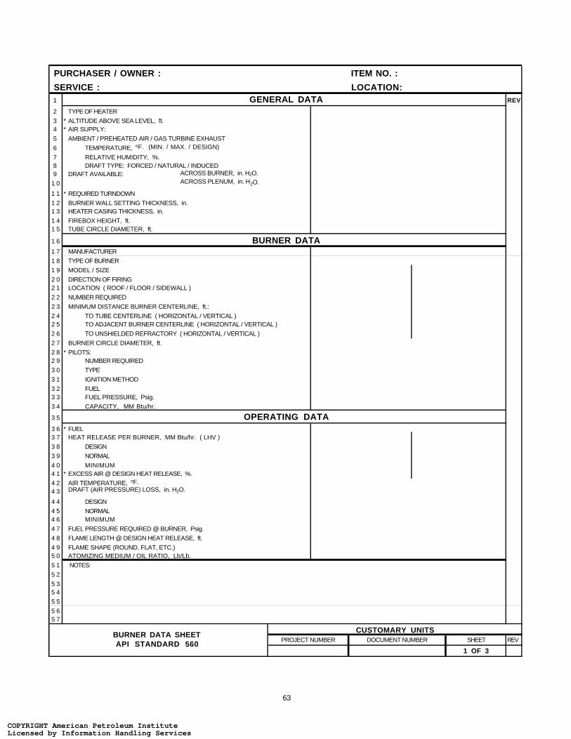
63
PURCHASER / OWNER : ITEM NO. :
SERVICE : LOCATION:1 GENERAL DATA REV
2 TYPE OF HEATER
3 * ALTITUDE ABOVE SEA LEVEL, ft.4 * AIR SUPPLY:
5 AMBIENT / PREHEATED AIR / GAS TURBINE EXHAUST
6 TEMPERATURE, oF. (MIN. / MAX. / DESIGN)
7 RELATIVE HUMIDITY, %.8 DRAFT TYPE: FORCED / NATURAL / INDUCED9 DRAFT AVAILABLE: ACROSS BURNER, in. H2O.
1 0 ACROSS PLENUM, in. H2O.
1 1 * REQUIRED TURNDOWN
1 2 BURNER WALL SETTING THICKNESS, in.1 3 HEATER CASING THICKNESS, in.
1 4 FIREBOX HEIGHT, ft.1 5 TUBE CIRCLE DIAMETER, ft.
1 6 BURNER DATA1 7 MANUFACTURER
1 8 TYPE OF BURNER
1 9 MODEL / SIZE
2 0 DIRECTION OF FIRING2 1 LOCATION ( ROOF / FLOOR / SIDEWALL )
2 2 NUMBER REQUIRED
2 3 MINIMUM DISTANCE BURNER CENTERLINE, ft.:
2 4 TO TUBE CENTERLINE ( HORIZONTAL / VERTICAL )2 5 TO ADJACENT BURNER CENTERLINE ( HORIZONTAL / VERTICAL )
2 6 TO UNSHIELDED REFRACTORY ( HORIZONTAL / VERTICAL )
2 7 BURNER CIRCLE DIAMETER, ft.
2 8 * PILOTS:2 9 NUMBER REQUIRED
3 0 TYPE
3 1 IGNITION METHOD
3 2 FUEL3 3 FUEL PRESSURE, Psig.
3 4 CAPACITY, MM Btu/hr.
3 5 OPERATING DATA3 6 * FUEL3 7 HEAT RELEASE PER BURNER, MM Btu/hr. ( LHV )
3 8 DESIGN
3 9 NORMAL
4 0 MINIMUM4 1 * EXCESS AIR @ DESIGN HEAT RELEASE, %.
4 2 AIR TEMPERATURE, oF.
4 3 DRAFT (AIR PRESSURE) LOSS, in. H2O.
4 4 DESIGN
4 5 NORMAL4 6 MINIMUM
4 7 FUEL PRESSURE REQUIRED @ BURNER, Psig.
4 8 FLAME LENGTH @ DESIGN HEAT RELEASE, ft.
4 9 FLAME SHAPE (ROUND, FLAT, ETC.)5 0 ATOMIZING MEDIUM / OIL RATIO, Lb/Lb.
5 1 NOTES:
5 2
5 35 4
5 5
5 65 7
PROJECT NUMBER DOCUMENT NUMBER SHEET REV
1 OF 3
CUSTOMARY UNITSBURNER DATA SHEETAPI STANDARD 560
COPYRIGHT American Petroleum InstituteLicensed by Information Handling ServicesCOPYRIGHT American Petroleum InstituteLicensed by Information Handling Services

64
GAS FUEL CHARACTERISTICS1 * FUEL TYPE REV2 * HEATING VALUE ( LHV ) , (
3 * SPECIFIC GRAVIRTY ( AIR = 1.0 )
4 * MOLECULAR WEIGHT5 * FUEL TEMPERATURE @ BURNER, oF.
6 * FUEL PRESSURE; AVAILABLE @ BURNER, Psig.
7 * FUEL GAS COMPOSITION, MOLE % .8 CH4
9 C2H6
1 0 C3H8
1 1 C4H101 2 C5H12
1 3 H2
1 4 N2
1 51 6 TOTAL
1 7 LIQUID FUEL CHARACTERISTICS1 8 * FUEL TYPE
1 9 * HEATING VALUE ( LHV ) , Btu/Lb.
2 0 * SPECIFIC GRAVITY / DEGREE API2 1 * H / C RATIO ( BY WEIGHT )
2 2 * VISCOSITY, @ oF. (SSU)
2 3 @ oF. (SSU)
2 4 * VANADIUM, ppm.2 5 * SODIUM, ppm.
2 6 * POTASSIUM, ppm.
2 7 * NICKEL, ppm.
2 8 * FIXED NITROGEN, ppm.2 9 * SULFUR, % wt.
3 0 * ASH, % wt.
3 1 * LIQUIDS: ASTM INITIAL BOILING POINT, oF.
3 2 ASTM END POINT, oF.3 3 * FUEL TEMPERATURE @ BURNER, oF.
3 4 * FUEL PRESSURE AVAILABLE / REQUIRED @ BURNER, Psig.
3 5 * ATOMIZING MEDIUM: AIR / STEAM / MECHANICAL
3 6 TEMPERATURE, oF.
3 7 PRESSURE, Psig.
3 8 MISCELLANEOUS3 9 BURNER PLENUM: COMMON / INTEGRAL
4 0 MATERIAL
4 1 PLATE THICKNESS, in.4 2 INTERNAL INSULATION
4 3 INLET AIR CONTROL: DAMPER OR REGISTERS
4 4 MODE OF OPERATION
4 5 LEAKAGE, %.4 6 BURNER TILE: COMPOSITION
4 7 MINIMUM SERVICE TEMPERATURE, oF.
4 8 NOISE SPECIFICATION
4 9 ATTENUATION METHOD 5 0 PAINTING REQUIREMENTS
5 1 IGNITION PORT: SIZE / NO.
5 2 SIGHT PORT: SIZE / NO.
5 3 * FLAME DETECTION: TYPE5 4 NUMBER / LOCATION
5 5 CONNECTION SIZE
5 6 SAFETY INTERLOCK SYSTEM FOR ATOMIZING MEDIUM & OIL5 7 * PERFORMANCE TEST REQUIRED (YES or NO)
5 8 NOTES:
5 96 0
PROJECT NUMBER DOCUMENT NUMBER SHEET REV
2 OF 3
( Btu/scf ) ( Btu/Lb )
CUSTOMARY UNITSBURNER DATA SHEETAPI STANDARD 560
COPYRIGHT American Petroleum InstituteLicensed by Information Handling ServicesCOPYRIGHT American Petroleum InstituteLicensed by Information Handling Services
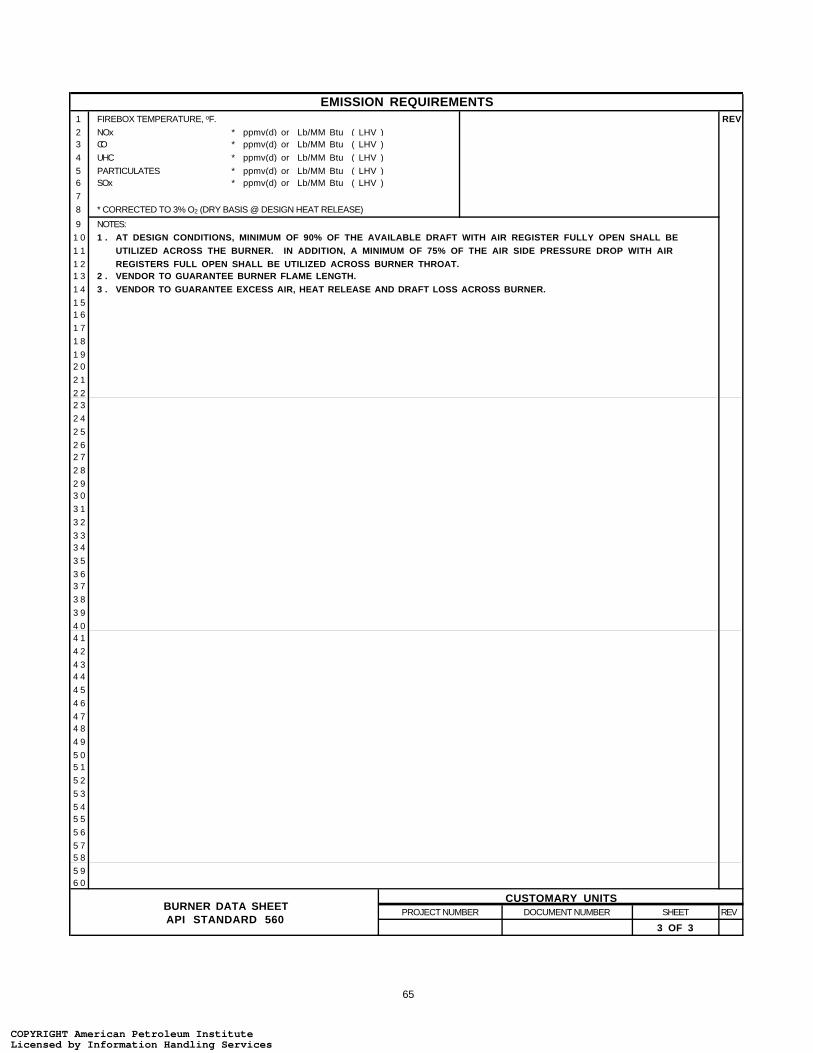
65
EMISSION REQUIREMENTS1 FIREBOX TEMPERATURE, oF. REV2 NOx3 CO
4 UHC
5 PARTICULATES6 SOx
7
8 * CORRECTED TO 3% O2 (DRY BASIS @ DESIGN HEAT RELEASE)
9 NOTES:
1 0 1 .1 1
1 21 3 2 .1 4 3 .1 51 6
1 7
1 8
1 92 0
2 1
2 22 3
2 4
2 5
2 62 7
2 8
2 93 0
3 1
3 2
3 33 4
3 5
3 63 7
3 8
3 9
4 04 1
4 2
4 34 4
4 5
4 6
4 74 8
4 9
5 05 1
5 2
5 3
5 45 5
5 6
5 75 8
5 96 0
PROJECT NUMBER DOCUMENT NUMBER SHEET REV
3 OF 3
* ppmv(d) or Lb/MM Btu ( LHV )* ppmv(d) or Lb/MM Btu ( LHV )
* ppmv(d) or Lb/MM Btu ( LHV )
* ppmv(d) or Lb/MM Btu ( LHV )
CUSTOMARY UNITS
* ppmv(d) or Lb/MM Btu ( LHV )
VENDOR TO GUARANTEE EXCESS AIR, HEAT RELEASE AND DRAFT LOSS ACROSS BURNER.
AT DESIGN CONDITIONS, MINIMUM OF 90% OF THE AVAILABLE DRAFT WITH AIR REGISTER FULLY OPEN SHALL BEUTILIZED ACROSS THE BURNER. IN ADDITION, A MINIMUM OF 75% OF THE AIR SIDE PRESSURE DROP WITH AIRREGISTERS FULL OPEN SHALL BE UTILIZED ACROSS BURNER THROAT.VENDOR TO GUARANTEE BURNER FLAME LENGTH.
BURNER DATA SHEETAPI STANDARD 560
COPYRIGHT American Petroleum InstituteLicensed by Information Handling ServicesCOPYRIGHT American Petroleum InstituteLicensed by Information Handling Services

66
PURCHASER / OWNER : ITEM NO. :
SERVICE : LOCATION:1 GENERAL DATA REV
2 TYPE OF HEATER
3 * ALTITUDE ABOVE SEA LEVEL, m.4 * AIR SUPPLY:
5 AMBIENT / PREHEATED AIR / GAS TURBINE EXHAUST
6 TEMPERATURE, oC. (MIN. / MAX. / DESIGN)
7 RELATIVE HUMIDITY, %.8 DRAFT TYPE: FORCED / NATURAL / INDUCED
9 DRAFT AVAILABLE: ACROSS BURNER, Pa.
1 0 ACROSS PLENUM, Pa.
1 1 * REQUIRED TURNDOWN
1 2 BURNER WALL SETTING THICKNESS, mm.1 3 HEATER CASING THICKNESS, mm.
1 4 FIREBOX HEIGHT, m.1 5 TUBE CIRCLE DIAMETER, m.
1 6 BURNER DATA1 7 MANUFACTURER
1 8 TYPE OF BURNER
1 9 MODEL / SIZE
2 0 DIRECTION OF FIRING2 1 LOCATION ( ROOF / FLOOR / SIDEWALL )
2 2 NUMBER REQUIRED
2 3 MINIMUM DISTANCE BURNER CENTERLINE, m.:
2 4 TO TUBE CENTERLINE ( HORIZONTAL / VERTICAL )2 5 TO ADJACENT BURNER CENTERLINE ( HORIZONTAL / VERTICAL )
2 6 TO UNSHIELDED REFRACTORY ( HORIZONTAL / VERTICAL )
2 7 BURNER CIRCLE DIAMETER, m.
2 8 * PILOTS:2 9 NUMBER REQUIRED
3 0 TYPE
3 1 IGNITION METHOD
3 2 FUEL3 3 FUEL PRESSURE, kPa.g.
3 4 CAPACITY, MW.
3 5 OPERATING DATA3 6 * FUEL3 7 HEAT RELEASE PER BURNER, MW. ( LHV )
3 8 DESIGN
3 9 NORMAL
4 0 MINIMUM4 1 * EXCESS AIR @ DESIGN HEAT RELEASE, %.
4 2 AIR TEMPERATURE, oC.
4 3 DRAFT (AIR PRESSURE) LOSS, Pa.
4 4 DESIGN
4 5 NORMAL4 6 MINIMUM
4 7 FUEL PRESSURE REQUIRED @ BURNER, kPa.g.
4 8 FLAME LENGTH @ DESIGN HEAT RELEASE, m.
4 9 FLAME SHAPE (ROUND, FLAT, ETC.)5 0 ATOMIZING MEDIUM / OIL RATIO, kg/kg.
5 1 NOTES:
5 2
5 35 4
5 5
5 65 7
PROJECT NUMBER DOCUMENT NUMBER SHEET REV
1 OF 3
SI UNITSBURNER DATA SHEETAPI STANDARD 560
COPYRIGHT American Petroleum InstituteLicensed by Information Handling ServicesCOPYRIGHT American Petroleum InstituteLicensed by Information Handling Services
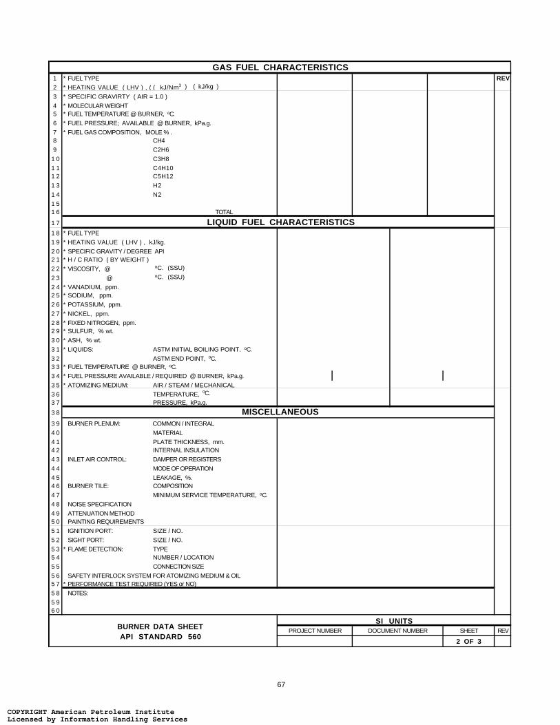
67
GAS FUEL CHARACTERISTICS1 * FUEL TYPE REV2 * HEATING VALUE ( LHV ) , (
3 * SPECIFIC GRAVIRTY ( AIR = 1.0 )
4 * MOLECULAR WEIGHT5 * FUEL TEMPERATURE @ BURNER, oC.
6 * FUEL PRESSURE; AVAILABLE @ BURNER, kPa.g.
7 * FUEL GAS COMPOSITION, MOLE % .8 CH4
9 C2H6
1 0 C3H8
1 1 C4H101 2 C5H12
1 3 H2
1 4 N2
1 51 6 TOTAL
1 7 LIQUID FUEL CHARACTERISTICS1 8 * FUEL TYPE
1 9 * HEATING VALUE ( LHV ) , kJ/kg.
2 0 * SPECIFIC GRAVITY / DEGREE API2 1 * H / C RATIO ( BY WEIGHT )
2 2 * VISCOSITY, @ oC. (SSU)
2 3 @ oC. (SSU)
2 4 * VANADIUM, ppm.2 5 * SODIUM, ppm.
2 6 * POTASSIUM, ppm.
2 7 * NICKEL, ppm.
2 8 * FIXED NITROGEN, ppm.2 9 * SULFUR, % wt.
3 0 * ASH, % wt.
3 1 * LIQUIDS: ASTM INITIAL BOILING POINT, oC.
3 2 ASTM END POINT, oC.3 3 * FUEL TEMPERATURE @ BURNER, oC.
3 4 * FUEL PRESSURE AVAILABLE / REQUIRED @ BURNER, kPa.g.
3 5 * ATOMIZING MEDIUM: AIR / STEAM / MECHANICAL
3 6 TEMPERATURE, oC.
3 7 PRESSURE, kPa.g.
3 8 MISCELLANEOUS3 9 BURNER PLENUM: COMMON / INTEGRAL
4 0 MATERIAL
4 1 PLATE THICKNESS, mm.4 2 INTERNAL INSULATION
4 3 INLET AIR CONTROL: DAMPER OR REGISTERS
4 4 MODE OF OPERATION
4 5 LEAKAGE, %.4 6 BURNER TILE: COMPOSITION
4 7 MINIMUM SERVICE TEMPERATURE, oC.
4 8 NOISE SPECIFICATION
4 9 ATTENUATION METHOD 5 0 PAINTING REQUIREMENTS
5 1 IGNITION PORT: SIZE / NO.
5 2 SIGHT PORT: SIZE / NO.
5 3 * FLAME DETECTION: TYPE5 4 NUMBER / LOCATION
5 5 CONNECTION SIZE
5 6 SAFETY INTERLOCK SYSTEM FOR ATOMIZING MEDIUM & OIL5 7 * PERFORMANCE TEST REQUIRED (YES or NO)
5 8 NOTES:
5 96 0
PROJECT NUMBER DOCUMENT NUMBER SHEET REV
2 OF 3
( kJ/Nm3 ) ( kJ/kg )
SI UNITSBURNER DATA SHEETAPI STANDARD 560
COPYRIGHT American Petroleum InstituteLicensed by Information Handling ServicesCOPYRIGHT American Petroleum InstituteLicensed by Information Handling Services
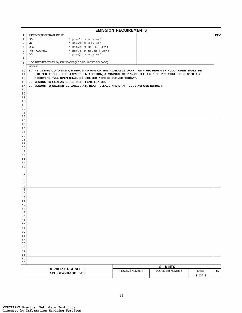
68
EMISSION REQUIREMENTS1 FIREBOX TEMPERATURE, oC. REV2 NOx3 CO
4 UHC
5 PARTICULATES6 SOx
7
8 * CORRECTED TO 3% O2 (DRY BASIS @ DESIGN HEAT RELEASE)
9 NOTES:
1 0 1 .1 1
1 2
1 3 2 .1 4 3 .1 5
1 6
1 71 8
1 9
2 0
2 12 2
2 3
2 4
2 52 6
2 7
2 82 9
3 0
3 1
3 23 3
3 4
3 53 6
3 7
3 8
3 94 0
4 1
4 2
4 34 4
4 5
4 64 7
4 8
4 9
5 05 1
5 2
5 3
5 45 5
5 6
5 75 8
5 96 0
PROJECT NUMBER DOCUMENT NUMBER SHEET REV
3 OF 3
* ppmv(d) or mg / Nm3
* ppmv(d) or mg / Nm3
* ppmv(d) or kg / kJ ( LHV )
* ppmv(d) or kg / kJ ( LHV )
SI UNITS
* ppmv(d) or mg / Nm3
VENDOR TO GUARANTEE EXCESS AIR, HEAT RELEASE AND DRAFT LOSS ACROSS BURNER.
AT DESIGN CONDITIONS, MINIMUM OF 90% OF THE AVAILABLE DRAFT WITH AIR REGISTER FULLY OPEN SHALL BEUTILIZED ACROSS THE BURNER. IN ADDITION, A MINIMUM OF 75% OF THE AIR SIDE PRESSURE DROP WITH AIRREGISTERS FULL OPEN SHALL BE UTILIZED ACROSS BURNER THROAT.VENDOR TO GUARANTEE BURNER FLAME LENGTH.
BURNER DATA SHEETAPI STANDARD 560
COPYRIGHT American Petroleum InstituteLicensed by Information Handling ServicesCOPYRIGHT American Petroleum InstituteLicensed by Information Handling Services

69
PURCHASER / OWNER : ITEM NO. : SERVICE : LOCATION :1 MANUFACTURER: REV2 MODEL:3 NUMBER REQUIRED:
4 HEATING SURFACE, ft2:
5 WEIGHT, Lbs.
6 APPROXIMATE DIMENSIONS: (H x W x L), ft.
7 PERFORMANCE DATA8 OPERATING CASE
9 AIR SIDE: FLOW ENTERING, Lb/hr.
1 0 INLET TEMPERATURE, oF.1 1 OUTLET TEMPERATURE, oF.
1 2 PRESSURE DROP: ALLOWABLE, in H2O.1 3 CALCULATED, in H2O.1 4 HEAT ABSORBED, MM Btu/hr.
1 5 FLUE GAS SIDE: FLOW, Lb/hr.
1 6 INLET TEMPERATURE, oF.1 7 OUTLET TEMPERATURE, oF.
1 8 PRESSURE DROP: ALLOWABLE, in H2O.1 9 CALCULATED, in H2O.2 0 HEAT EXCHANGED, MM Btu/hr.
2 1 AIR BY-PASS, Lb/hr.2 2 TOTAL AIR FLOW TO BURNERS, Lb/hr.
2 3 MIX AIR TEMPERATURE, oF.2 4 FLUE GAS COMPOSITION, mole%:
2 5 O2
2 6 N2
2 7 H2O2 8 CO2
2 9 A r3 0 SOx
3 1 TOTAL
3 2 FLUE GAS SPECIFIC HEAT, Btu/Lb-oF.3 3 FLUE GAS ACID DEW POINT TEMPERATURE, oF.3 4 * MINIMUM METAL TEMPERATURE: ALLOWABLE, oF.3 5 CALCULATED, oF.
3 6 MISCELLANEOUS3 7 * MINIMUM AMBIENT AIR TEMPERATURE, oF.
3 8 * SITE ELEVATION ABOVE SEA LEVEL, ft.
3 9 * RELATIVE HUMIDITY, %.
4 0 EXTERNAL COLD AIR BY - PASS (YES / NO)4 1 COLD END THERMOCOUPLES (YES / NO) / NO. REQUIRED.
4 2 ACCESS DOORS : NUMBER / SIZE / LOCATION
4 3 INSULATION (INTERNAL / EXTERNAL):
4 4 * CLEANING MEDIUM: STEAM OR WATER4 5 PRESSURE, Psig.
4 6 TEMPERATURE, oF.4 7 * LEAK TEST
4 8 AIR LEAKAGE (GUARANTEED), %.4 9 NOTES: ( ALL DATA ON PER UNIT BASIS )
5 0
5 1
5 25 3
5 4
5 5
5 65 7
5 8
PROJECT NUMBER DOCUMENT NUMBER SHEET REV
1 OF 2
CUSTOMARY UNITSAIR PREHEATER DATA SHEET
API STANDARD 560
COPYRIGHT American Petroleum InstituteLicensed by Information Handling ServicesCOPYRIGHT American Petroleum InstituteLicensed by Information Handling Services

70
MECHANICAL DESIGN1 DESIGN FLUE GAS TEMPERATURE, oF. REV2 DESIGN PRESSURE DIFFERENTIAL, in H2O.
3 * SEISMIC FACTOR4 * PAINTING REQUIREMENTS
5 * STRUCTURAL WIND LOAD, Psf.
6 CONSTRUCTION DATA7 I . CAST IRON :8 NUMBER OF PASSES9 NUMBER OF TUBES PER BLOCK
1 0 NUMBER OF BLOCK
1 1 TYPE OF SURFACE1 2 TUBE MATERIAL
1 3 TUBE THICKNESS, in.
1 4 GLASS BLOCK (YES / NO)
1 5 NUMBER OF GLASS TUBES
1 6 AIR CROSS-OVER DUCT: NUMBER1 7 BOLTED / WELDED
1 8 SUPPLIED WITH CLIPS
1 9 WATER WASH : YES / NO
2 0 TYPE (OFF-LINE OR ON-LINE)2 1 LOCATION
2 2 I I . PLATE TYPE :2 3 NUMBER OF PASSES2 4 NUMBER OF PLATES PER BLOCK
2 5 NUMBER OF BLOCKS
2 6 PLATE THICKNESS, in.
2 7 WIDTH OF AIR CHANNEL, in.2 8 WIDTH OF FLUE GAS CHANNEL, in.
2 9 AIR SIDE RIB PITCH, in.
3 0 FLUE GAS SIDE RIB PITCH, in.
3 1 MATERIAL: PLATE3 2 RIB
3 3 FRAME
3 4 AIR CROSS-OVER DUCT: NUMBER
3 5 BOLTED / WELDED3 6 SUPPLIED WITH CLIPS
3 7 WATER WASH : YES / NO
3 8 TYPE (OFF-LINE OR ON-LINE)3 9 LOCATION
4 0 I I I . HEAT PIPE :4 1 NUMBER OF TUBES
4 2 TUBE O.D. / WALL THICKNESS, in.4 3 TUBE MATERIAL
4 4 TUBES PER ROW
4 5 NUMBER OF ROWS4 6 TUBE PITCH (SQUARE / TRIANGULAR), in.
4 7 AIR SIDE GAS SIDE
4 8 FINS: TYPE
4 9 HEIGHT x THICKNESS x NUMBER / in.5 0 MATERIAL
5 1 EFFECTIVE LENGTH, ft.
5 2 HEATING SURFACE, ft2.
5 3 MAXIMUM ALLOWABLE SOAK TEMPERATURE, oF.
5 4 SOOT BLOWER: YES / NO5 5 TYPE5 6 LOCATION
5 7 NOTES:
5 85 9
6 06 1
PROJECT NUMBER DOCUMENT NUMBER SHEET REV
2 OF 2
CUSTOMARY UNITSAIR PREHEATER DATA SHEET
API STANDARD 560
COPYRIGHT American Petroleum InstituteLicensed by Information Handling ServicesCOPYRIGHT American Petroleum InstituteLicensed by Information Handling Services
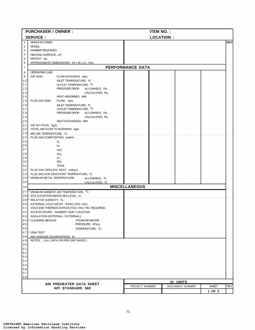
71
PURCHASER / OWNER : ITEM NO. : SERVICE : LOCATION :1 MANUFACTURER: REV2 MODEL:3 NUMBER REQUIRED:
4 HEATING SURFACE, m2:
5 WEIGHT, kg.
6 APPROXIMATE DIMENSIONS: (H x W x L), mm.
7 PERFORMANCE DATA8 OPERATING CASE
9 AIR SIDE: FLOW ENTERING, kg/s.
1 0 INLET TEMPERATURE, oC.1 1 OUTLET TEMPERATURE, oC.
1 2 PRESSURE DROP: ALLOWABLE, Pa.
1 3 CALCULATED, Pa.1 4 HEAT ABSORBED, MW.
1 5 FLUE GAS SIDE: FLOW, kg/s.
1 6 INLET TEMPERATURE, oC.1 7 OUTLET TEMPERATURE, oC.
1 8 PRESSURE DROP: ALLOWABLE, Pa.
1 9 CALCULATED, Pa.
2 0 HEAT EXCHANGED, MW.
2 1 AIR BY-PASS, kg/s.2 2 TOTAL AIR FLOW TO BURNERS, kg/s.
2 3 MIX AIR TEMPERATURE, oC.2 4 FLUE GAS COMPOSITION, mole%:
2 5 O2
2 6 N2
2 7 H2O2 8 CO2
2 9 A r3 0 SOx
3 1 TOTAL
3 2 FLUE GAS SPECIFIC HEAT, kJ/kg-K.
3 3 FLUE GAS ACID DEW POINT TEMPERATURE, oC.3 4 * MINIMUM METAL TEMPERATURE: ALLOWABLE, oC.3 5 CALCULATED, oC.
3 6 MISCELLANEOUS3 7 * MINIMUM AMBIENT AIR TEMPERATURE, oC.
3 8 * SITE ELEVATION ABOVE SEA LEVEL, m.
3 9 * RELATIVE HUMIDITY, %.
4 0 EXTERNAL COLD AIR BY - PASS (YES / NO)4 1 COLD END THERMOCOUPLES (YES / NO) / NO. REQUIRED.
4 2 ACCESS DOORS : NUMBER / SIZE / LOCATION
4 3 INSULATION (INTERNAL / EXTERNAL):
4 4 * CLEANING MEDIUM: STEAM OR WATER4 5 PRESSURE, kPa.g.
4 6 TEMPERATURE, oC.4 7 * LEAK TEST
4 8 AIR LEAKAGE (GUARANTEED), %.4 9 NOTES: ( ALL DATA ON PER UNIT BASIS )
5 0
5 1
5 25 3
5 4
5 5
5 65 7
5 8
PROJECT NUMBER DOCUMENT NUMBER SHEET REV
1 OF 2
SI UNITSAIR PREHEATER DATA SHEET
API STANDARD 560
COPYRIGHT American Petroleum InstituteLicensed by Information Handling ServicesCOPYRIGHT American Petroleum InstituteLicensed by Information Handling Services

72
MECHANICAL DESIGN1 DESIGN FLUE GAS TEMPERATURE, oC. REV2 DESIGN PRESSURE DIFFERENTIAL, Pa.
3 * SEISMIC FACTOR4 * PAINTING REQUIREMENTS
5 * STRUCTURAL WIND LOAD, kg/m2.
6 CONSTRUCTION DATA7 I . CAST IRON :8 NUMBER OF PASSES9 NUMBER OF TUBES PER BLOCK
1 0 NUMBER OF BLOCK
1 1 TYPE OF SURFACE1 2 TUBE MATERIAL
1 3 TUBE THICKNESS, mm.
1 4 GLASS BLOCK (YES / NO)
1 5 NUMBER OF GLASS TUBES
1 6 AIR CROSS-OVER DUCT: NUMBER1 7 BOLTED / WELDED
1 8 SUPPLIED WITH CLIPS
1 9 WATER WASH : YES / NO
2 0 TYPE (OFF-LINE OR ON-LINE)2 1 LOCATION
2 2 I I . PLATE TYPE :2 3 NUMBER OF PASSES2 4 NUMBER OF PLATES PER BLOCK
2 5 NUMBER OF BLOCKS
2 6 PLATE THICKNESS, mm.
2 7 WIDTH OF AIR CHANNEL, mm.2 8 WIDTH OF FLUE GAS CHANNEL, mm.
2 9 AIR SIDE RIB PITCH, mm.
3 0 FLUE GAS SIDE RIB PITCH, mm.
3 1 MATERIAL: PLATE3 2 RIB
3 3 FRAME
3 4 AIR CROSS-OVER DUCT: NUMBER
3 5 BOLTED / WELDED3 6 SUPPLIED WITH CLIPS
3 7 WATER WASH : YES / NO
3 8 TYPE (OFF-LINE OR ON-LINE)3 9 LOCATION
4 0 I I I . HEAT PIPE :4 1 NUMBER OF TUBES
4 2 TUBE O.D. / WALL THICKNESS, mm.4 3 TUBE MATERIAL
4 4 TUBES PER ROW
4 5 NUMBER OF ROWS4 6 TUBE PITCH (SQUARE / TRIANGULAR), mm.
4 7 AIR SIDE GAS SIDE
4 8 FINS: TYPE
4 9 HEIGHT(mm) x THICKNESS(mm) x NUMBER / m.5 0 MATERIAL
5 1 EFFECTIVE LENGTH, m.
5 2 HEATING SURFACE, m2.
5 3 MAXIMUM ALLOWABLE SOAK TEMPERATURE, oC.
5 4 SOOT BLOWER: YES / NO5 5 TYPE5 6 LOCATION
5 7 NOTES:
5 85 9
6 06 1
PROJECT NUMBER DOCUMENT NUMBER SHEET REV
2 OF 2
SI UNITSAIR PREHEATER DATA SHEET
API STANDARD 560
COPYRIGHT American Petroleum InstituteLicensed by Information Handling ServicesCOPYRIGHT American Petroleum InstituteLicensed by Information Handling Services

73
PURCHASER / OWNER : ITEM NO. : SERVICE : LOCATION :1 FAN MANUFACTURER : MODEL / SIZE : ARRANGEMENT : REV2 SERVICE : *NO. REQUIRED : 3 * DRIVE SYSTEM : FAN ROTATION FROM DRIVEN END : CCW CW 4 GAS HANDLED : MOLECULAR WEIGHT : 5 * SITE ELEVATION, ft. : FAN LOCATION :
6 OPERATING CONDITIONS 7 OPERATING CONDITION / CASE : DESIGN TEST BLOCK8 CAPACITY, Lb/hr.9 CAPACITY, ACFM.
1 0 DENSITY, Lb/ft3.
1 1 TEMPERATURE , oF.
1 2 RELATIVE HUMIDITY, %1 3 STATIC PRESSURE @ INLET, in. H2O.
1 4 STATIC PRESSURE @ OUTLET, in. H2 O.
1 5 PERFORMANCE :1 6 BHP @ TEMPERATURE ( ALL LOSSES INCLUDED )1 7 FAN SPEED, RPM.1 8 STATIC PRESSURE RISE ACROSS FAN, in. H2O.
1 9 INLET DAMPER / VANE POSITION
2 0 DISCHARGE DAMPER POSITION2 1 FAN STATIC EFFICIENCY, %.2 2 STEAM RATE, Lb/hp-hr. (TURBINE ONLY)
2 3 FAN CONTROL : DRIVER :2 4 * AIR SUPPLY: MAKE TYPE2 5 FAN CONTROL FURNISHED BY: RATED Hp RPM
2 6 METHOD : INLET DAMPER OUTLET DAMPER * ELECTRICAL AREA CLASSIFICATION
2 7 INLET GUIDE VANES VARIABLE SPEED CLASS GROUP DIVISION2 8 STARTING METHOD: POWER Volts Ph Hz
2 9 CONSTRUCTION FEATURES 3 0 HOUSING : BEARINGS :3 1 MATERIAL THICKNESS , in. HYDRODYNAMIC ANTI - FRICTION3 2 SPLIT FOR WHEEL REMOVAL YES NO TYPE LUBRICATION
3 3 DRAINS, NO. / SIZE COOLANT REQUIRED GPM WATER @ oF.
3 4 ACCESS DOORS, NO. / SIZE THERMOSTATICALLY CONTROLLED HEATERS YES NO
3 5 BLADES : TEMPERATURE DETECTORS YES NO3 6 TYPE VIBRATION DETECTORS YES NO
3 7 NO. THICKNESS, in.
3 8 MATERIAL SPEED DETECTORS :3 9 HUB : NON - CONTACT PROBE4 0 SHRINK FIT KEYED SPEED SWITCH
4 1 MATERIAL OTHER
4 2 SHAFT : COUPLINGS :4 3 MATERIAL TYPE4 4 DIAMETER @ BRGS., in. MAKE
4 5 SHAFT SLEEVES : MODEL
4 6 MATERIAL SERVICE FACTOR
4 7 SHAFT SEALS : MOUNT COUPLING HALVES4 8 TYPE FAN DRIVER
4 9 SPACER YES NO LENGTH, in.5 0 W R 2, Lb-ft2 :
5 1 NOTES: (ALL DATA ON PER UNIT BASIS)5 2
5 3
5 4
5 55 6
5 75 8
PROJECT NUMBER DOCUMENT NUMBER SHEET REV
CUSTOMARY UNITS
1 OF 2
FAN DATA SHEETAPI STANDARD 560
COPYRIGHT American Petroleum InstituteLicensed by Information Handling ServicesCOPYRIGHT American Petroleum InstituteLicensed by Information Handling Services
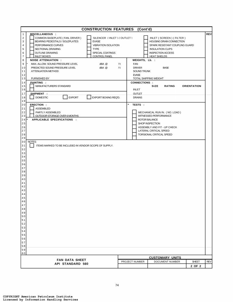
74
CONSTRUCTION FEATURES (Cont'd)1 MISCELLANEOUS : REV2 COMMON BASEPLATE ( FAN, DRIVER ) SILENCER ( INLET ) ( OUTLET ) INLET ( SCREEN ) ( FILTER )3 BEARING PEDESTALS / SOLEPLATES EVASE HOUSING DRAIN CONNECTION
4 PERFORMANCE CURVES VIBRATION ISOLATION SPARK RESISTANT COUPLING GUARD
5 SECTIONAL DRAWING TYPE INSULATION CLIPS
6 OUTLINE DRAWING SPECIAL COATINGS INSPECTION ACCESS7 INLET BOXES CONTROL PANEL HEAT SHIELDS
8 NOISE ATTENUATION : WEIGHTS, Lb. :9 * MAX. ALLOW. SOUND PRESSURE LEVEL dBA @ f t FAN
1 0 PREDICTED SOUND PRESSURE LEVEL dBA @ f t DRIVER BASE1 1 ATTENUATION METHOD SOUND TRUNK
1 2 EVASE1 3 FURNISHED BY TOTAL SHIPPING WEIGHT
1 4 PAINTING : CONNECTIONS :1 5 MANUFACTURERS STANDARD SIZE RATING ORIENTATION1 6 INLET
1 7 SHIPMENT : OUTLET
1 8 DOMESTIC EXPORT EXPORT BOXING REQ'D. DRAINS1 9
2 0 ERECTION : * TESTS :2 1 ASSEMBLED 2 2 PARTLY ASSEMBLED MECHANICAL RUN IN. ( NO. LOAD )2 3 OUTDOOR STORAGE OVER 6 MONTHS WITNESSED PERFORMANCE
2 4 * APPLICABLE SPECIFICATIONS : ROTOR BALANCE
2 5 SHOP INSPECTION
2 6 ASSEMBLY AND FIT - UP CHECK2 7 LATERAL CRITICAL SPEED
2 8 TORSIONAL CRITICAL SPEED2 9
3 0 NOTES:
3 1 ITEMS MARKED TO BE INCLUDED IN VENDOR SCOPE OF SUPPLY.
3 2
3 33 4
3 5
3 6
3 73 8
3 9
4 0
4 14 2
4 3
4 4
4 54 6
4 7
4 8
4 95 0
5 1
5 2
5 35 4
5 5
5 6
5 75 8
5 96 0
PROJECT NUMBER DOCUMENT NUMBER SHEET REV
2 OF 2
CUSTOMARY UNITSFAN DATA SHEET
API STANDARD 560
COPYRIGHT American Petroleum InstituteLicensed by Information Handling ServicesCOPYRIGHT American Petroleum InstituteLicensed by Information Handling Services

75
PURCHASER / OWNER : ITEM NO. : SERVICE : LOCATION :1 FAN MANUFACTURER : MODEL / SIZE : ARRANGEMENT : REV2 SERVICE : *NO. REQUIRED : 3 * DRIVE SYSTEM : FAN ROTATION FROM DRIVEN END : CCW CW 4 GAS HANDLED : MOLECULAR WEIGHT : 5 * SITE ELEVATION, m. : FAN LOCATION :
6 OPERATING CONDITIONS 7 OPERATING CONDITION / CASE : DESIGN TEST BLOCK8 CAPACITY, kg/s.9 CAPACITY, Am3/ s .
1 0 DENSITY, kg/m3.
1 1 TEMPERATURE , oC.
1 2 RELATIVE HUMIDITY, %1 3 STATIC PRESSURE @ INLET, Pa.
1 4 STATIC PRESSURE @ OUTLET, Pa.
1 5 PERFORMANCE :1 6 kW @ TEMPERATURE ( ALL LOSSES INCLUDED )1 7 FAN SPEED, RPM.
1 8 STATIC PRESSURE RISE ACROSS FAN, Pa.
1 9 INLET DAMPER / VANE POSITION
2 0 DISCHARGE DAMPER POSITION2 1 FAN STATIC EFFICIENCY, %.2 2 STEAM RATE, kg/kWh. (TURBINE ONLY)
2 3 FAN CONTROL : DRIVER :2 4 * AIR SUPPLY: MAKE TYPE2 5 FAN CONTROL FURNISHED BY: RATED kW RPM
2 6 METHOD : INLET DAMPER OUTLET DAMPER ELECTRICAL AREA CLASSIFICATION
2 7 INLET GUIDE VANES VARIABLE SPEED CLASS GROUP DIVISION2 8 STARTING METHOD: POWER Volts Ph Hz
2 9 CONSTRUCTION FEATURES 3 0 HOUSING : BEARINGS :3 1 MATERIAL THICKNESS , mm. HYDRODYNAMIC ANTI - FRICTION3 2 SPLIT FOR WHEEL REMOVAL YES NO TYPE LUBRICATION
3 3 DRAINS, NO. / SIZE COOLANT REQUIRED m3/s WATER @ oC.
3 4 ACCESS DOORS, NO. / SIZE THERMOSTATICALLY CONTROLLED HEATERS YES NO
3 5 BLADES : TEMPERATURE DETECTORS YES NO3 6 TYPE VIBRATION DETECTORS YES NO
3 7 NO. THICKNESS, mm.
3 8 MATERIAL SPEED DETECTORS :3 9 HUB : NON - CONTACT PROBE4 0 SHRINK FIT KEYED SPEED SWITCH
4 1 MATERIAL OTHER
4 2 SHAFT : COUPLINGS :4 3 MATERIAL TYPE4 4 DIAMETER @ BRGS., mm. MAKE
4 5 SHAFT SLEEVES : MODEL
4 6 MATERIAL SERVICE FACTOR
4 7 SHAFT SEALS : MOUNT COUPLING HALVES4 8 TYPE FAN DRIVER
4 9 SPACER YES NO LENGTH, mm.5 0 W R 2, kg-m2 :
5 1 NOTES: (ALL DATA ON PER UNIT BASIS)5 2
5 3
5 4
5 55 6
5 75 8
PROJECT NUMBER DOCUMENT NUMBER SHEET REV
1 OF 2
SI UNITSFAN DATA SHEET
API STANDARD 560
COPYRIGHT American Petroleum InstituteLicensed by Information Handling ServicesCOPYRIGHT American Petroleum InstituteLicensed by Information Handling Services

76
CONSTRUCTION FEATURES (Cont'd)1 MISCELLANEOUS : REV2 COMMON BASEPLATE ( FAN, DRIVER ) SILENCER ( INLET ) ( OUTLET ) INLET ( SCREEN ) ( FILTER )3 BEARING PEDESTALS / SOLEPLATES EVASE HOUSING DRAIN CONNECTION
4 PERFORMANCE CURVES VIBRATION ISOLATION SPARK RESISTANT COUPLING GUARD
5 SECTIONAL DRAWING TYPE INSULATION CLIPS
6 OUTLINE DRAWING SPECIAL COATINGS INSPECTION ACCESS7 INLET BOXES CONTROL PANEL HEAT SHIELDS
8 NOISE ATTENUATION : WEIGHTS, kg. :9 * MAX. ALLOW. SOUND PRESSURE LEVEL dBA @ m. FAN
1 0 PREDICTED SOUND PRESSURE LEVEL dBA @ m. DRIVER BASE1 1 ATTENUATION METHOD SOUND TRUNK
1 2 EVASE1 3 FURNISHED BY TOTAL SHIPPING WEIGHT
1 4 PAINTING : CONNECTIONS :1 5 MANUFACTURERS STANDARD SIZE RATING ORIENTATION1 6 INLET
1 7 SHIPMENT : OUTLET
1 8 DOMESTIC EXPORT EXPORT BOXING REQ'D. DRAINS1 9
2 0 ERECTION : * TESTS :2 1 ASSEMBLED 2 2 PARTLY ASSEMBLED MECHANICAL RUN IN. ( NO. LOAD )2 3 OUTDOOR STORAGE OVER 6 MONTHS WITNESSED PERFORMANCE
2 4 * APPLICABLE SPECIFICATIONS : ROTOR BALANCE
2 5 SHOP INSPECTION
2 6 ASSEMBLY AND FIT - UP CHECK2 7 LATERAL CRITICAL SPEED
2 8 TORSIONAL CRITICAL SPEED2 9
3 0 NOTES:
3 1 ITEMS MARKED TO BE INCLUDED IN VENDOR SCOPE OF SUPPLY.
3 2
3 33 4
3 5
3 6
3 73 8
3 9
4 0
4 14 2
4 3
4 4
4 54 6
4 7
4 8
4 95 0
5 1
5 2
5 35 4
5 5
5 6
5 75 8
5 96 0
PROJECT NUMBER DOCUMENT NUMBER SHEET REV
2 OF 2
SI UNITSFAN DATA SHEET
API STANDARD 560
COPYRIGHT American Petroleum InstituteLicensed by Information Handling ServicesCOPYRIGHT American Petroleum InstituteLicensed by Information Handling Services
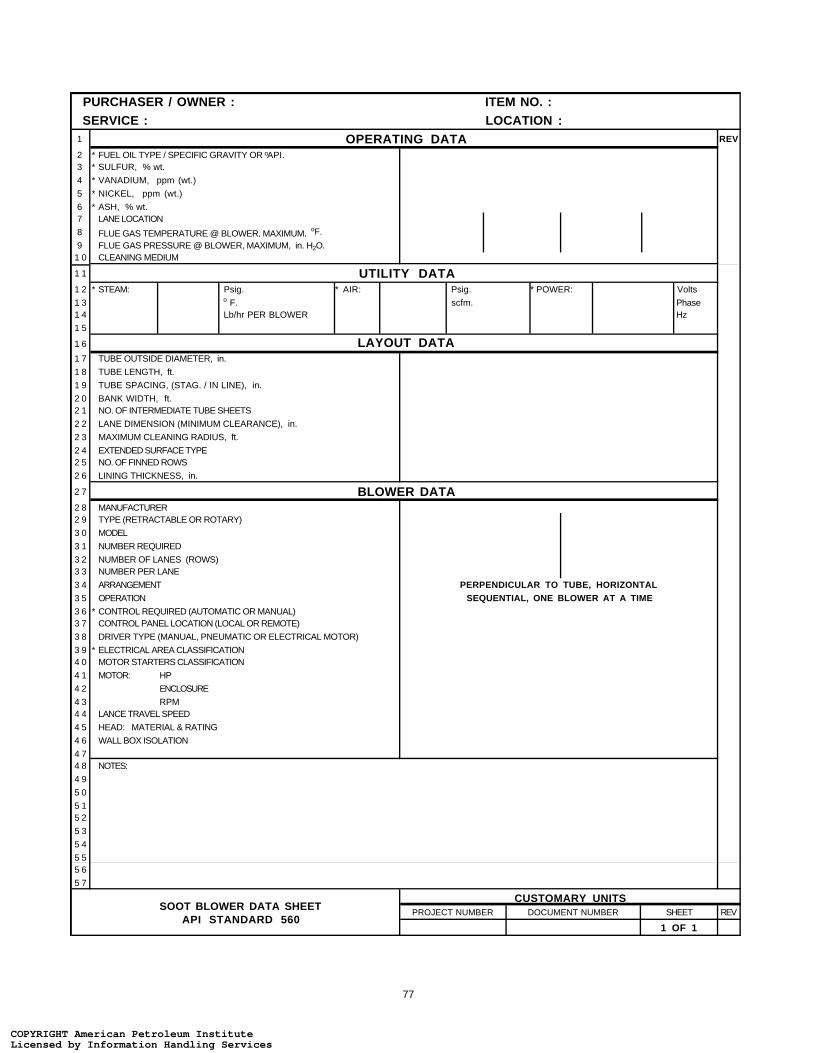
77
PURCHASER / OWNER : ITEM NO. : SERVICE : LOCATION :1 OPERATING DATA REV
2 * FUEL OIL TYPE / SPECIFIC GRAVITY OR oAPI.3 * SULFUR, % wt.
4 * VANADIUM, ppm (wt.)
5 * NICKEL, ppm (wt.)
6 * ASH, % wt.7 LANE LOCATION
8 FLUE GAS TEMPERATURE @ BLOWER, MAXIMUM, oF.
9 FLUE GAS PRESSURE @ BLOWER, MAXIMUM, in. H2O.1 0 CLEANING MEDIUM
1 1 UTILITY DATA1 2 * STEAM: Psig. * AIR: Psig. * POWER: Volts
1 3 o F. scfm. Phase1 4 Lb/hr PER BLOWER Hz
1 5
1 6 LAYOUT DATA1 7 TUBE OUTSIDE DIAMETER, in.
1 8 TUBE LENGTH, ft.
1 9 TUBE SPACING, (STAG. / IN LINE), in.
2 0 BANK WIDTH, ft.2 1 NO. OF INTERMEDIATE TUBE SHEETS
2 2 LANE DIMENSION (MINIMUM CLEARANCE), in.
2 3 MAXIMUM CLEANING RADIUS, ft.
2 4 EXTENDED SURFACE TYPE2 5 NO. OF FINNED ROWS
2 6 LINING THICKNESS, in.
2 7 BLOWER DATA2 8 MANUFACTURER2 9 TYPE (RETRACTABLE OR ROTARY)
3 0 MODEL
3 1 NUMBER REQUIRED
3 2 NUMBER OF LANES (ROWS)3 3 NUMBER PER LANE
3 4 ARRANGEMENT
3 5 OPERATION
3 6 * CONTROL REQUIRED (AUTOMATIC OR MANUAL)3 7 CONTROL PANEL LOCATION (LOCAL OR REMOTE)
3 8 DRIVER TYPE (MANUAL, PNEUMATIC OR ELECTRICAL MOTOR)
3 9 * ELECTRICAL AREA CLASSIFICATION4 0 MOTOR STARTERS CLASSIFICATION
4 1 MOTOR: HP
4 2 ENCLOSURE
4 3 RPM4 4 LANCE TRAVEL SPEED
4 5 HEAD: MATERIAL & RATING
4 6 WALL BOX ISOLATION
4 74 8 NOTES:
4 9
5 0
5 15 2
5 3
5 4
5 55 6
5 7
PROJECT NUMBER DOCUMENT NUMBER SHEET REV
PERPENDICULAR TO TUBE, HORIZONTALSEQUENTIAL, ONE BLOWER AT A TIME
1 OF 1
CUSTOMARY UNITSSOOT BLOWER DATA SHEET
API STANDARD 560
COPYRIGHT American Petroleum InstituteLicensed by Information Handling ServicesCOPYRIGHT American Petroleum InstituteLicensed by Information Handling Services

78
PURCHASER / OWNER : ITEM NO. : SERVICE : LOCATION :1 OPERATING DATA REV
2 * FUEL OIL TYPE / SPECIFIC GRAVITY OR oAPI.3 * SULFUR, % wt.
4 * VANADIUM, ppm (wt.)
5 * NICKEL, ppm (wt.)
6 * ASH, % wt.7 LANE LOCATION
8 FLUE GAS TEMPERATURE @ BLOWER, MAXIMUM, oC.
9 FLUE GAS PRESSURE @ BLOWER, MAXIMUM, Pa.1 0 CLEANING MEDIUM
1 1 UTILITY DATA1 2 * STEAM: kPa.g. * AIR: kPa.g. * POWER: Volts
1 3 o C. Nm3/ h r . Phase1 4 kg/s PER BLOWER Hz
1 5
1 6 LAYOUT DATA1 7 TUBE OUTSIDE DIAMETER, mm.
1 8 TUBE LENGTH, m.
1 9 TUBE SPACING, (STAG. / IN LINE), mm.
2 0 BANK WIDTH, m.2 1 NO. OF INTERMEDIATE TUBE SHEETS
2 2 LANE DIMENSION (MINIMUM CLEARANCE), mm.
2 3 MAXIMUM CLEANING RADIUS, m.
2 4 EXTENDED SURFACE TYPE2 5 NO. OF FINNED ROWS
2 6 LINING THICKNESS, mm.
2 7 BLOWER DATA2 8 MANUFACTURER2 9 TYPE (RETRACTABLE OR ROTARY)
3 0 MODEL
3 1 NUMBER REQUIRED
3 2 NUMBER OF LANES (ROWS)3 3 NUMBER PER LANE
3 4 ARRANGEMENT
3 5 OPERATION
3 6 * CONTROL REQUIRED (AUTOMATIC OR MANUAL)3 7 CONTROL PANEL LOCATION (LOCAL OR REMOTE)
3 8 DRIVER TYPE (MANUAL, PNEUMATIC OR ELECTRICAL MOTOR)
3 9 * ELECTRICAL AREA CLASSIFICATION4 0 MOTOR STARTERS CLASSIFICATION
4 1 MOTOR: kW
4 2 ENCLOSURE
4 3 RPM4 4 LANCE TRAVEL SPEED
4 5 HEAD: MATERIAL & RATING
4 6 WALL BOX ISOLATION
4 74 8 NOTES:
4 9
5 0
5 15 2
5 3
5 4
5 55 6
5 7
PROJECT NUMBER DOCUMENT NUMBER SHEET REV
1 OF 1
SI UNITS
PERPENDICULAR TO TUBE, HORIZONTALSEQUENTIAL, ONE BLOWER AT A TIME
SOOT BLOWER DATA SHEETAPI STANDARD 560
COPYRIGHT American Petroleum InstituteLicensed by Information Handling ServicesCOPYRIGHT American Petroleum InstituteLicensed by Information Handling Services

79
APPENDIX B—PURCHASER’S CHECKLIST
This checklist is to be used for indicating the purchaser’s specific requirements when thestandard provides a choice or designates that a decision must be made. These items are indi-cated by a bullet (•) in this standard. This completed checklist shall be considered part of thespecification.
COPYRIGHT American Petroleum InstituteLicensed by Information Handling ServicesCOPYRIGHT American Petroleum InstituteLicensed by Information Handling Services

COPYRIGHT American Petroleum InstituteLicensed by Information Handling ServicesCOPYRIGHT American Petroleum InstituteLicensed by Information Handling Services
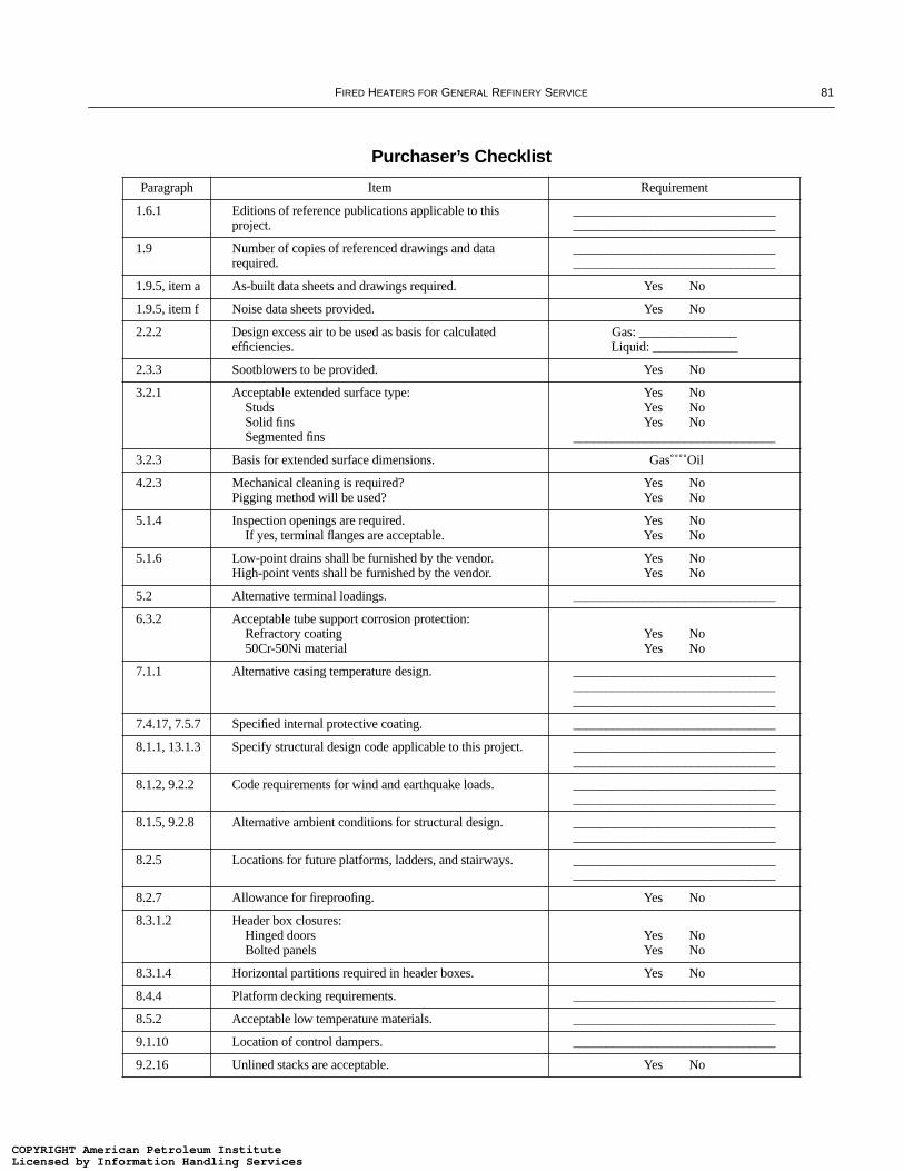
FIRED HEATERS FOR GENERAL REFINERY SERVICE 81
Purchaser’s Checklist
Paragraph Item Requirement
1.6.1 Editions of reference publications applicable to this project.
______________________________________________________________
1.9 Number of copies of referenced drawings and data required.
______________________________________________________________
1.9.5, item a As-built data sheets and drawings required. Yes No
1.9.5, item f Noise data sheets provided. Yes No
2.2.2 Design excess air to be used as basis for calculated efficiencies.
Gas: _______________Liquid: _____________
2.3.3 Sootblowers to be provided. Yes No
3.2.1 Acceptable extended surface type:StudsSolid finsSegmented fins
Yes NoYes NoYes No
_______________________________
3.2.3 Basis for extended surface dimensions. Gas Oil
4.2.3 Mechanical cleaning is required?Pigging method will be used?
Yes NoYes No
5.1.4 Inspection openings are required.If yes, terminal flanges are acceptable.
Yes NoYes No
5.1.6 Low-point drains shall be furnished by the vendor.High-point vents shall be furnished by the vendor.
Yes NoYes No
5.2 Alternative terminal loadings. _______________________________
6.3.2 Acceptable tube support corrosion protection:Refractory coating50Cr-50Ni material
Yes NoYes No
7.1.1 Alternative casing temperature design. _____________________________________________________________________________________________
7.4.17, 7.5.7 Specified internal protective coating. _______________________________
8.1.1, 13.1.3 Specify structural design code applicable to this project. ______________________________________________________________
8.1.2, 9.2.2 Code requirements for wind and earthquake loads. ______________________________________________________________
8.1.5, 9.2.8 Alternative ambient conditions for structural design. ______________________________________________________________
8.2.5 Locations for future platforms, ladders, and stairways. ______________________________________________________________
8.2.7 Allowance for fireproofing. Yes No
8.3.1.2 Header box closures:Hinged doorsBolted panels
Yes NoYes No
8.3.1.4 Horizontal partitions required in header boxes. Yes No
8.4.4 Platform decking requirements. _______________________________
8.5.2 Acceptable low temperature materials. _______________________________
9.1.10 Location of control dampers. _______________________________
9.2.16 Unlined stacks are acceptable. Yes No
COPYRIGHT American Petroleum InstituteLicensed by Information Handling ServicesCOPYRIGHT American Petroleum InstituteLicensed by Information Handling Services

82 API STANDARD 560
9.5.4 Acceptable strake design:Staggered platesSpiral spoilers
Yes NoYes No
_______________________________
9.6.1 Acceptable materials of construction: Stacks Ducts Breechings
_____________________________________________________________________________________________
9.6.2 Acceptable bolting materials. _______________________________
10.1.4 Alternative basis for burner sizing. _______________________________
10.1.5 Single burner with multiple guns is acceptable. Yes No
10.1.6 Pilots for gas burners. Yes No
10.1.13 Required heater capacity during forced draft outage and continued operation on natural draft.
______________________________________________________________
10.1.18 On-stream removal of complete burner assembly isrequired.
Yes No_______________________________
10.2.1 Acceptable sootblower type:RetractableAutomaticSequential
Yes NoYes NoYes No
10.2.5 Acceptable erosion protection:Stainless shroudsHigh-duty brickCastable refractory
Yes NoYes NoYes No
10.3.1 Damper position on failure. Open Close
11.1.2.2 Required static pressure and temperature atrate point.
______________________________________________________________
11.1.4 Electrical area classification for fired heater equipment/system.
______________________________________________________________
11.1.7 Weather and environmental requirements for outdoor installation.
______________________________________________________________
11.3.1 Fan speed is limited to 1800 RPM.If no, max. speed allowed?
Yes No_______________________________
11.3.10 Alternative requirement for air intake height above grade. ______________________________________________________________
11.4.1 Corrosion allowance required for fan scroll and housing. Yes No_______________________________
11.7.2 Blade design required for I.D. fan. _______________________________
11.7.5 An un-keyed fit-up of impeller to the shaftis acceptable.
Yes No
11.7.8 Corrosion-resistant shaft sleeves required for I.D. fans. Yes No
11.9.4 Rotor response analysis required. Yes No
11.10.3,11.22.3.1
Mechanical run test required. Other tests?
Yes No_______________________________
11.13.2 Environmental conditions of flue gas and air affecting fan material selections.
_____________________________________________________________________________________________
11.16.1,11.16.2
Fan driver type and sizing basis. ______________________________________________________________
Purchaser’s Checklist (Continued)
Paragraph Item Requirement
COPYRIGHT American Petroleum InstituteLicensed by Information Handling ServicesCOPYRIGHT American Petroleum InstituteLicensed by Information Handling Services
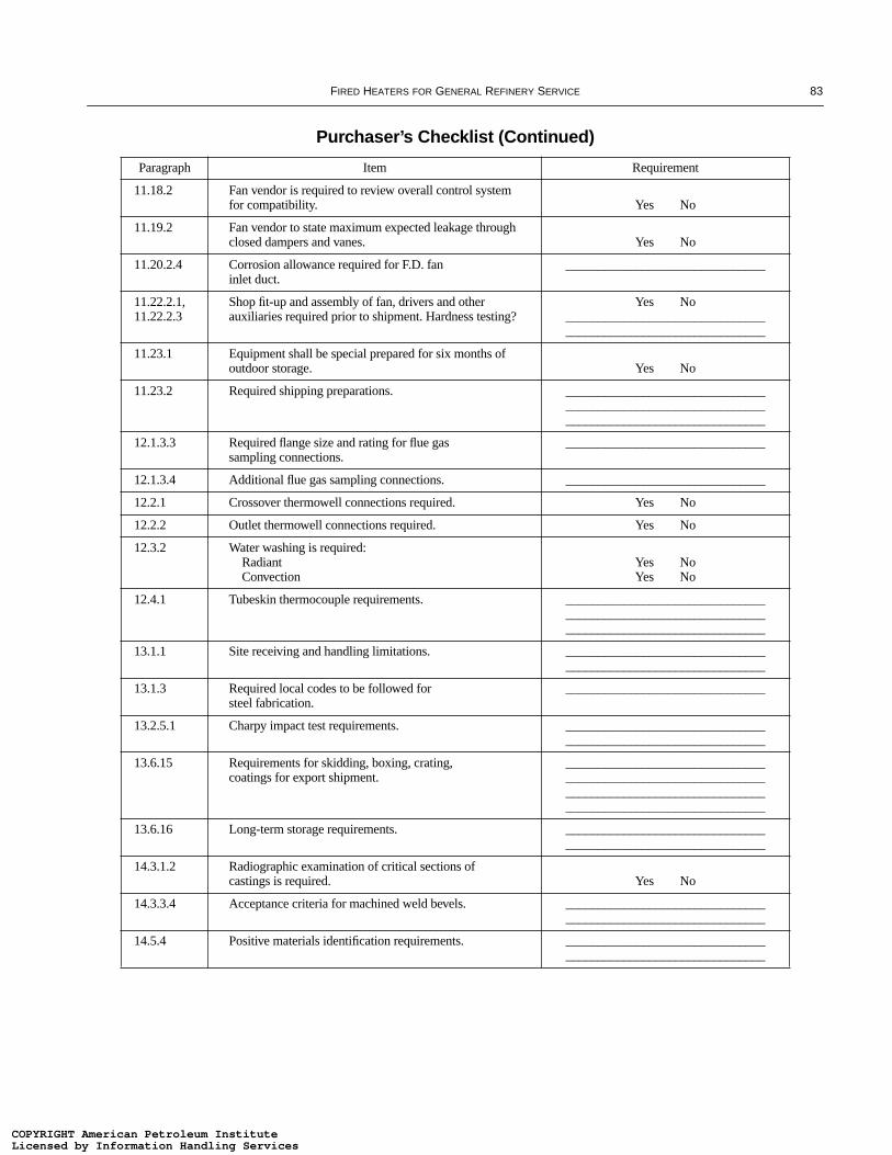
FIRED HEATERS FOR GENERAL REFINERY SERVICE 83
11.18.2 Fan vendor is required to review overall control system for compatibility. Yes No
11.19.2 Fan vendor to state maximum expected leakage through closed dampers and vanes. Yes No
11.20.2.4 Corrosion allowance required for F.D. faninlet duct.
_______________________________
11.22.2.1,11.22.2.3
Shop fit-up and assembly of fan, drivers and other auxiliaries required prior to shipment. Hardness testing?
Yes No______________________________________________________________
11.23.1 Equipment shall be special prepared for six months ofoutdoor storage. Yes No
11.23.2 Required shipping preparations. _____________________________________________________________________________________________
12.1.3.3 Required flange size and rating for flue gassampling connections.
_______________________________
12.1.3.4 Additional flue gas sampling connections. _______________________________
12.2.1 Crossover thermowell connections required. Yes No
12.2.2 Outlet thermowell connections required. Yes No
12.3.2 Water washing is required:RadiantConvection
Yes NoYes No
12.4.1 Tubeskin thermocouple requirements. _____________________________________________________________________________________________
13.1.1 Site receiving and handling limitations. ______________________________________________________________
13.1.3 Required local codes to be followed forsteel fabrication.
_______________________________
13.2.5.1 Charpy impact test requirements. ______________________________________________________________
13.6.15 Requirements for skidding, boxing, crating,coatings for export shipment.
____________________________________________________________________________________________________________________________
13.6.16 Long-term storage requirements. ______________________________________________________________
14.3.1.2 Radiographic examination of critical sections of castings is required. Yes No
14.3.3.4 Acceptance criteria for machined weld bevels. ______________________________________________________________
14.5.4 Positive materials identification requirements. ______________________________________________________________
Purchaser’s Checklist (Continued)
Paragraph Item Requirement
COPYRIGHT American Petroleum InstituteLicensed by Information Handling ServicesCOPYRIGHT American Petroleum InstituteLicensed by Information Handling Services

COPYRIGHT American Petroleum InstituteLicensed by Information Handling ServicesCOPYRIGHT American Petroleum InstituteLicensed by Information Handling Services
85
APPENDIX C—PROPOSED SHOP ASSEMBLY CONDITIONS
COPYRIGHT American Petroleum InstituteLicensed by Information Handling ServicesCOPYRIGHT American Petroleum InstituteLicensed by Information Handling Services

COPYRIGHT American Petroleum InstituteLicensed by Information Handling ServicesCOPYRIGHT American Petroleum InstituteLicensed by Information Handling Services
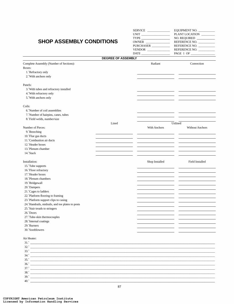
87
SHOP ASSEMBLY CONDITIONS
SERVICE _______________ EQUIPMENT NO. ___________UNIT ___________________ PLANT LOCATION _________TYPE ___________________ NO. REQUIRED ____________OWNER ________________ REFERENCE NO. ___________PURCHASER ____________ REFERENCE NO. ___________VENDOR _______________ REFERENCE NO. ___________DATE ___________________ PAGE 1 OF ________________
DEGREE OF ASSEMBLY
Complete Assembly (Number of Sections): Radiant ConvectionBoxes:
1. Refractory only2. With anchors only
Panels:3. With tubes and refractory installed4. With refractory only5. With anchors only
Coils:6. Number of coil assemblies7. Number of hairpins, canes, tubes8. Field welds, number/size
Lined UnlinedNumber of Pieces: With Anchors Without Anchors
9. Breeching10. Flue gas ducts11. Combustion air ducts12. Header boxes13. Plenum chamber14. Stack
Installation: Shop Installed Field Installed15. Tube supports16. Floor refractory17. Header boxes18. Plenum chambers19. Bridgewall20. Dampers21. Cages to ladders22. Platform flooring to framing23. Platform support clips to casing24. Handrails, midrails, and toe plates to posts25. Stair treads to stringers26. Doors27. Tube-skin thermocouples28. Internal coatings29. Burners30. Sootblowers
Air Heater:31. ___________________________________________________________________________________________________________________________32. ___________________________________________________________________________________________________________________________33. ___________________________________________________________________________________________________________________________34. ___________________________________________________________________________________________________________________________35. ___________________________________________________________________________________________________________________________36. ___________________________________________________________________________________________________________________________37. ___________________________________________________________________________________________________________________________38. ___________________________________________________________________________________________________________________________39. ___________________________________________________________________________________________________________________________40. ___________________________________________________________________________________________________________________________
COPYRIGHT American Petroleum InstituteLicensed by Information Handling ServicesCOPYRIGHT American Petroleum InstituteLicensed by Information Handling Services

88
SHOP ASSEMBLY CONDITIONS
SERVICE _______________ EQUIPMENT NO. ___________UNIT ___________________ PLANT LOCATION _________TYPE ___________________ NO. REQUIRED ____________OWNER ________________ REFERENCE NO. ___________PURCHASER ____________ REFERENCE NO. ___________VENDOR _______________ REFERENCE NO. ___________DATE ___________________ PAGE 2 OF ________________
DEGREE OF ASSEMBLY (continued)
Fans:
1. ___________________________________________________________________________________________________________________________
2. ___________________________________________________________________________________________________________________________
3. ___________________________________________________________________________________________________________________________
Drivers:
4. ___________________________________________________________________________________________________________________________
5. ___________________________________________________________________________________________________________________________
6. ___________________________________________________________________________________________________________________________
Other:
7. ___________________________________________________________________________________________________________________________
8. ___________________________________________________________________________________________________________________________
9. ___________________________________________________________________________________________________________________________
ESTIMATED SHIPPING WEIGHTS AND DIMENSIONS
10. Total heater weight, in tons
11. Total, ladders, stairs, platform, in tons
12. Total stack, in tons
13. Maximum radiant section, in tons
14. Maximum radiant section dimensions, length x width x height
15. Maximum convection section, in tons
16. Maximum convection section dimensions, length x width x height
COPYRIGHT American Petroleum InstituteLicensed by Information Handling ServicesCOPYRIGHT American Petroleum InstituteLicensed by Information Handling Services

89
APPENDIX D—STRESS CURVES FOR USE IN THE DESIGN OF TUBE SUPPORT ELEMENTS
D.1 ScopeThis appendix provides stress curves that shall be used in
the design of tube support elements. The range of tube sup-port materials has been expanded from that presented in Table8 of Standard 560 to include 21/4Cr-1Mo castings and plateand 50Cr-50Ni-Cb castings. The following stress curves areprovided:
a. One-third of the ultimate tensile strength.
b. Two-thirds of the yield strength (0.2 percent offset).
c. Fifty percent of the average stress required to produce 1percent creep in 10,000 hours
d. Fifty percent of the average stress required to produce rup-ture in 10,000 hours.
Some of the stresses listed in items a. through d. were notavailable for carbon steel castings or plate or for 50Cr-50Ni-Cb castings.
The stress curves were plotted from data gathered over nor-mal design ranges. All of the materials are suitable for appli-cation at lower temperatures.
D.2 Referenced PublicationsThe following specifications and other publications are ref-
erenced in this appendix:
ASM14
Metals Handbook, Volume 3, “Properties and Selection:Stainless Steels, Tool Materials and Spe-cial-Purpose Metals” (Ninth Edition, 1980)
ASTM15
A 216 Carbon Steel Castings Suitable for FusionWelding for High-Temperature Service
A 217 Martensitic Stainless and Alloy Steel Cast-ings for Pressure-Containing PartsSuitable for High-Temperature Service
A 240 Heat-Resisting Chromium and Chromium-Nickel Stainless Steel Plate, Sheet, andStrip for Pressure Vessels
A 283 Low and Intermediate Tensile StrengthCarbon Steel Plates, Shapes, and Bars
A 297 Heat-Resistant Iron-Chromium and Iron-Chromium-Nickel Steel Castings for Gen-eral Application
A 351 Austenitic Castings for Pressure-Contain-ing Parts
A 387 Chromium-Molybdenum Alloy Steel Pres-sure Vessel Plates
A 447 Chromium-Nickel-Iron Alloy Steel Cast-ings (25-12 Class) for High-TemperatureService
A 560 Chromium-Nickel Alloy CastingsDS 5 Report on the Elevated-Temperature Prop-
erties of Stainless SteelsDS 5S2 An Evaluation of the Yield, Tensile, Creep,
and Rupture Strengths of Wrought 304,316, 321 and 347 Stainless Steels at Ele-vated Temperatures
DS 6 Report on the Elevated Temperature Prop-erties of Chromium-Molybdenum Steels
DS 6S2 Supplemental Report on the Elevated Tem-perature Properties of Chromium-Molybdenum Steels
DS 11S1 An Evaluation of the Elevated TemperatureTensile and Creep-Rupture Properties ofWrought Carbon Steel
DS 58 Evaluation of the Elevated TemperatureTensile and Creep-Rupture Properties of 3to 9 Percent Chromium-MolybdenumSteels
SFSA16
Steel Castings Handbook (Fifth Edition, 1980)
D.3 Casting FactorFor cast materials, the stresses shown in Figures D-1
through D-13 are actual stresses based on published dataaccepted by the industry. A casting-factor multiplier of 0.8shall be applied to the allowable stress value in the calculationof the minimum thickness.
D.4 Minimum Cross SectionsWhen good foundry practice or casting methods or toler-
ances require the use of a cross section heavier than thatbased on the calculation specified in D.3 or the stress curvesshown in Figures D-1 through D-13, the governing thicknessmust be specified.14American Society for Metals International, 9639 Kinsman Road,
Metals Park, Ohio 44073.15American Society for Testing and Materials, 100 Bar HarborDrive, West Conshohocken, Pennsylvania 19428-2959.
16Steel Founders’ Society of America, 205 Park Avenue, Barrington,Illinois 60010-4332.
COPYRIGHT American Petroleum InstituteLicensed by Information Handling ServicesCOPYRIGHT American Petroleum InstituteLicensed by Information Handling Services
90 API STANDARD 560
D.5 Maximum Design Temperatures
The maximum design temperatures shown in Figures D-1through D-13 were obtained from Table 8 of API Standard560 and are based on resistance to oxidation, except for themaximum design temperatures shown in Figures D-10 and D-12 (Types 309H and 310H plate), which are based on avail-able stress data. The stress curves for some materials extendbeyond the maximum design temperature because of thematerials’ possible use, with high oxidation rates, at highertemperatures.
D.6 Corrosion Resistance
ASTM A 560, Grade 50Cr-50Ni-Cb, material is generallyselected for its resistance to vanadium attack; however, itsresistance diminishes at temperatures above 1600°F.
D.7 Proprietary AlloysMany low chromium, alloy cast iron or high chromium/
nickel alloys are proprietary material items. The allowablestresses to be used for the design of castings that would usematerials not included in Table 8, must therefore be obtainedfrom the supplier and agreed upon by the purchaser.
D.8 Stress CurvesAll the stress curves in Figures D-1 through D-13 are based
on published data. Apparent anomalies in the shapes of thecurves reflect the actual data points used to construct thecurves.
D.9 Data SourcesTable D-1 lists the sources of the stress data presented in
Figures D-1 through D-13.
COPYRIGHT American Petroleum InstituteLicensed by Information Handling ServicesCOPYRIGHT American Petroleum InstituteLicensed by Information Handling Services

FIRED HEATERS FOR GENERAL REFINERY SERVICE 91
Table D-1—Sources of Data Presented in Figures D-1 Through D-13
Figure Material Curve Data Source
D-1 Carbon steel castings Tensile strength SFSA Steel Castings HandbookYield strength SFSA Steel Castings Handbook
D-2 Carbon steel plate Tensile strength ASTM DS 11S1Yield strength ASTM DS 11S1
D-3 21/4Cr-1Mo castings Tensile strength ASTM DS 6Yield strength ASTM DS 6S2Rupture stress ASTM DS 6S2Creep stress ASTM DS 6S2
D-4 21/4Cr-1Mo plate Tensile strength ASTM DS 6S2Yield strength ASTM DS 6S2Creep stress ASTM DS 6S2
D-5 5Cr-1/2Mo castings Tensile strength ASTM DS 6Yield strength ASTM DS 58Rupture stress ASTM DS 58Creep stress ASTM DS 58
D-6 5Cr-1/2Mo plate Tensile strength ASTM DS 58Yield strength ASTM DS 58Rupture stress ASTM DS 58Creep stress ASTM DS 58
D-7 19Cr-9Ni castings Tensile strength ASM Metals HandbookYield strength ASM Metals HandbookRupture stress ASM Metals HandbookCreep stress ASM Metals Handbook
D-8 Type 304H plate Tensile strength ASTM DS 5S2Yield strength ASTM DS 5S2Rupture stress ASTM DS 5S2Creep stress ASTM DS 5S2
D-9 25Cr-12Ni castings Tensile strength ASM Metals HandbookYield strength ASM Metals HandbookRupture stress ASM Metals HandbookCreep stress ASM Metals Handbook
D-10 Type 309H plate Tensile strength ASTM DS 5Yield strength ASTM DS 5Rupture stress ASTM DS 5Creep stress ASTM DS 5
D-11 25Cr-20Ni castings Tensile strength ASM Metals HandbookYield strength ASM Metals HandbookRupture stress ASM Metals HandbookCreep stress ASM Metals Handbook
D-12 Type 310H plate Tensile strength ASTM DS 5Yield strength ASTM DS 5Rupture stress ASTM DS 5Creep stress ASTM DS 5
D-13 50Cr-50Ni-Cb castings Rupture stress IN-657a
Creep stress IN-657a
aIN-657 Cast Nickel-Chromium-Niobium Alloy for Service Against Fuel-Ash Corrosion-Engineering Properties, Inco Alloy Products Ltd., Wiggin Street, Birmingham B16 0AJ, England, United Kingdom.
COPYRIGHT American Petroleum InstituteLicensed by Information Handling ServicesCOPYRIGHT American Petroleum InstituteLicensed by Information Handling Services

92 API STANDARD 560
Figure D-1—Carbon Steel Castings: ASTM A 216, Grade WCB
70
60
20
30
40
50
10
300 400 500 600 700 800 900
TEMPERATURE, °F
ST
RE
SS
, KIP
S P
ER
SQ
UA
RE
INC
H
Max
imum
des
ign
tem
pera
ture
1/3 Tensile strength
2/3 Yield strength
COPYRIGHT American Petroleum InstituteLicensed by Information Handling ServicesCOPYRIGHT American Petroleum InstituteLicensed by Information Handling Services

FIRED HEATERS FOR GENERAL REFINERY SERVICE 93
Figure D-2—Carbon Steel Plate: ASTM A 283, Grade C
50
40
9
10
20
30
1300 400 500 600 700 800 900
8
4
5
6
7
3
2
1000 1100
Max
imum
des
ign
tem
pera
ture
ST
RE
SS
, KIP
S P
ER
SQ
UA
RE
INC
H
TEMPERATURE, °F
1/3 Tensile strength
2/3 Yield strength
COPYRIGHT American Petroleum InstituteLicensed by Information Handling ServicesCOPYRIGHT American Petroleum InstituteLicensed by Information Handling Services

94 API STANDARD 560
Figure D-3—21/4Cr-1Mo Castings: ASTM A 217, Grade WC9
50
40
9
10
20
30
1700 800 900 1000 1100 1200
8
4
5
6
7
3
2
1300
Max
imum
des
ign
tem
pera
ture
1/3 Tensile strength
2/3 Yield strength
50% of rupture in 10,000 hours
50% of 1%
creep in 10,000 hours
ST
RE
SS
, KIP
S P
ER
SQ
UA
RE
INC
H
TEMPERATURE, °F
COPYRIGHT American Petroleum InstituteLicensed by Information Handling ServicesCOPYRIGHT American Petroleum InstituteLicensed by Information Handling Services
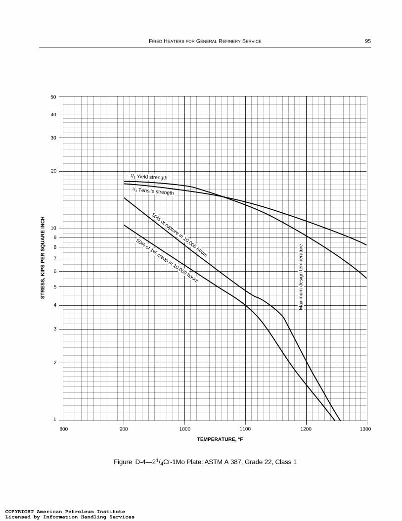
FIRED HEATERS FOR GENERAL REFINERY SERVICE 95
Figure D-4—21/4Cr-1Mo Plate: ASTM A 387, Grade 22, Class 1
50
40
9
10
20
30
1
800 900 1000 1100 1200
TEMPERATURE, °F
8
4
5
6
7
3
2
1300
2/3 Yield strength
1/3 Tensile strength
50% of rupture in 10,000 hours
Max
imum
des
ign
tem
pera
ture
ST
RE
SS
, KIP
S P
ER
SQ
UA
RE
INC
H
50% of 1% creep in 10,000 hours
COPYRIGHT American Petroleum InstituteLicensed by Information Handling ServicesCOPYRIGHT American Petroleum InstituteLicensed by Information Handling Services
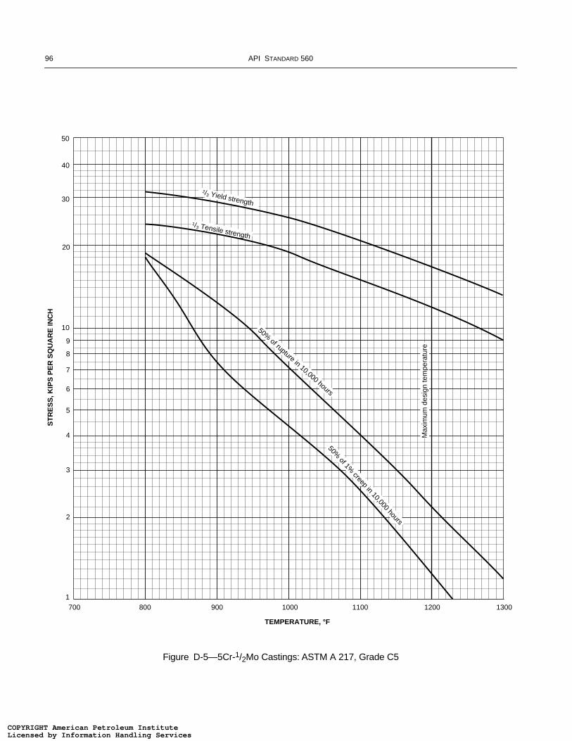
96 API STANDARD 560
Figure D-5—5Cr-1/2Mo Castings: ASTM A 217, Grade C5
50
40
9
10
20
30
1700 800 900 1000 1100 1200
TEMPERATURE, °F
8
4
5
6
7
3
2
1300
Max
imum
des
ign
tem
pera
ture
1/3 Tensile strength
2/3 Yield strength
50% of rupture in 10,000 hours
50% of 1%
creep in 10,000 hours
ST
RE
SS
, KIP
S P
ER
SQ
UA
RE
INC
H
COPYRIGHT American Petroleum InstituteLicensed by Information Handling ServicesCOPYRIGHT American Petroleum InstituteLicensed by Information Handling Services

FIRED HEATERS FOR GENERAL REFINERY SERVICE 97
Figure D-6—5Cr-1/2Mo Plate: ASTM A 387, Grade 5, Class 1
50
40
9
10
20
30
1
700 800 900 1000 1100 1200
TEMPERATURE, °F
8
4
5
6
7
3
2
1300 1400
Max
imum
des
ign
tem
pera
ture
50% of rupture in 10,000 hours
50% of 1%
creep in 10,000 hours
ST
RE
SS
, KIP
S P
ER
SQ
UA
RE
INC
H
2/3 Yield strength
1/3 Tensile strength
COPYRIGHT American Petroleum InstituteLicensed by Information Handling ServicesCOPYRIGHT American Petroleum InstituteLicensed by Information Handling Services

98 API STANDARD 560
Figure D-7—19Cr-9Ni Castings: ASTM A 297, Grade HF
40
3
10
20
30
0.11100 1200 1300 1400 1500 1600
TEMPERATURE, °F
2
4
1
5
7
0.7
0.5
1700
0.3
0.4
0.2
1/3 Tensile strength
2/3 Yield strength
Max
imum
des
ign
tem
pera
ture
50% of rupture in 10,000 hours
50% of 1% creep in 10,000 hours
ST
RE
SS
, KIP
S P
ER
SQ
UA
RE
INC
H
COPYRIGHT American Petroleum InstituteLicensed by Information Handling ServicesCOPYRIGHT American Petroleum InstituteLicensed by Information Handling Services

FIRED HEATERS FOR GENERAL REFINERY SERVICE 99
Figure D-8—Type 304H Plate: ASTM A 240, Type 304H
40
3
10
20
30
0.11000 1100 1200 1300 1400 1500
TEMPERATURE, °F
2
4
1
5
7
0.7
0.5
1600
0.3
0.4
0.2
Max
imum
des
ign
tem
pera
ture
1/3 Tensile strength
2/3 Yield strength
50% of rupture in 10,000 hours
50% of 1% creep in 10,000 hours
ST
RE
SS
, KIP
S P
ER
SQ
UA
RE
INC
H
900
COPYRIGHT American Petroleum InstituteLicensed by Information Handling ServicesCOPYRIGHT American Petroleum InstituteLicensed by Information Handling Services

100 API STANDARD 560
Figure D-9—25Cr-12Ni Castings: ASTM A 447, Type II
40
3
10
20
30
0.11200 1300 1400 1500 1600 1700
TEMPERATURE, °F
2
4
1
5
7
0.7
0.5
1800
0.3
0.4
0.2
1900
Max
imum
des
ign
tem
pera
ture
2000
1/3 Tensile strength
2/3 Yield strength
50% of creep in 10,000 hours50% of 1% rupture in 10,000 hours
ST
RE
SS
, KIP
S P
ER
SQ
UA
RE
INC
H
COPYRIGHT American Petroleum InstituteLicensed by Information Handling ServicesCOPYRIGHT American Petroleum InstituteLicensed by Information Handling Services
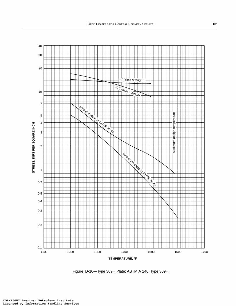
FIRED HEATERS FOR GENERAL REFINERY SERVICE 101
Figure D-10—Type 309H Plate: ASTM A 240, Type 309H
40
3
10
20
30
0.11100 1200 1300 1400 1500 1600
TEMPERATURE, °F
2
4
1
5
7
0.7
0.5
1700
0.3
0.4
0.2
1/3 Tensile strength
2/3 Yield strength
Max
imum
des
ign
tem
pera
ture
50% of rupture in 10,000 hours
50% of 1%
creep in 10,000 hours
ST
RE
SS
, KIP
S P
ER
SQ
UA
RE
INC
H
COPYRIGHT American Petroleum InstituteLicensed by Information Handling ServicesCOPYRIGHT American Petroleum InstituteLicensed by Information Handling Services

102 API STANDARD 560
Figure D-11—25Cr-20Ni Castings: ASTM A 351, Grade HK 40
40
3
10
20
30
0.11400 1500 1600 1700 1800 1900
TEMPERATURE, °F
2
4
1
5
7
0.7
0.5
2000
0.3
0.4
0.2
Max
imum
des
ign
tem
pera
ture
1/3 Tensile strength
2/3 Yield strength
50% of rupture in 10,000 hours
50% of 1% creep in 10,000 hours
ST
RE
SS
, KIP
S P
ER
SQ
UA
RE
INC
H
COPYRIGHT American Petroleum InstituteLicensed by Information Handling ServicesCOPYRIGHT American Petroleum InstituteLicensed by Information Handling Services
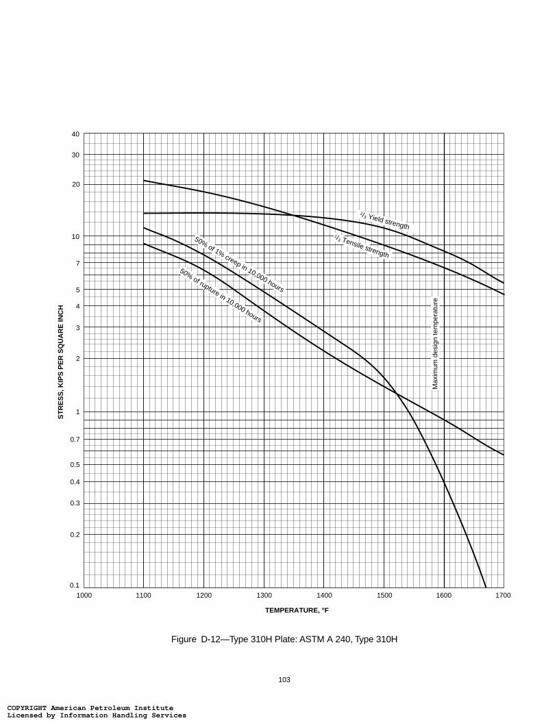
103
Figure D-12—Type 310H Plate: ASTM A 240, Type 310H
40
3
10
20
30
0.11000 1100 1200 1300 1400 1500
TEMPERATURE, °F
2
4
1
5
7
0.7
0.5
1600
0.3
0.4
0.2
1/3 Tensile strength
2/3 Yield strength
50% of rupture in 10,000 hours
50% of 1% creep in 10,000 hours
1700
Max
imum
des
ign
tem
pera
ture
ST
RE
SS
, KIP
S P
ER
SQ
UA
RE
INC
H
COPYRIGHT American Petroleum InstituteLicensed by Information Handling ServicesCOPYRIGHT American Petroleum InstituteLicensed by Information Handling Services
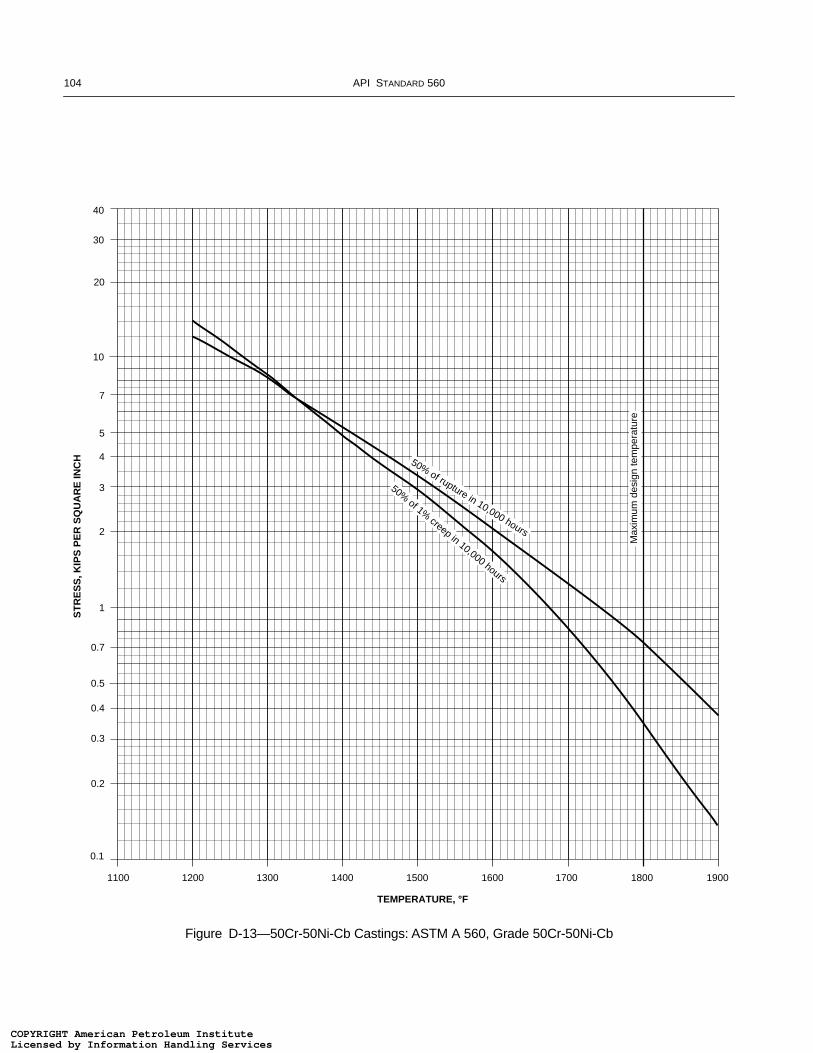
104 API STANDARD 560
Figure D-13—50Cr-50Ni-Cb Castings: ASTM A 560, Grade 50Cr-50Ni-Cb
40
3
10
20
30
0.1
1100 1200 1300 1400 1500 1600
TEMPERATURE, °F
2
4
1
5
7
0.7
0.5
1700
0.3
0.4
0.2
50% of 1% creep in 10,000 hours
1800 1900
Max
imum
des
ign
tem
pera
ture
50% of rupture in 10,000 hours
ST
RE
SS
, KIP
S P
ER
SQ
UA
RE
INC
H
COPYRIGHT American Petroleum InstituteLicensed by Information Handling ServicesCOPYRIGHT American Petroleum InstituteLicensed by Information Handling Services
105
APPENDIX E—AIR PREHEAT SYSTEMS FOR FIRED PROCESS HEATERS
E.1 General
E.1.1 SCOPE
This appendix provides guidelines for the design, selec-tion and evaluation of air preheat systems applied to firedprocess heaters. The primary concepts covered within thisappendix are:
a. General application considerations (E.2).
b. General design considerations (E.3).
c. Selection guidelines (E.4).
d. Safety, operations, and maintenance considerations (E.5).
e. Exchanger performance guidelines (E.6).
f. Fan sizing and performance guidelines (E.7).
g. Duct design and damper selection guidelines (E.8).
h. Equipment specification guidelines (E.9).
i. Environmental impact of APH systems (E.10).
Details of fired heater design are considered only wherethey interact with the air preheat (APH) system design. Theair preheat systems discussed in detail are those currently incommon use within the industry and it is not intended toimply that other systems are not recommended. Many of theindividual features dealt with in these guidelines are applica-ble to any type of air preheat system.
E.1.2 REFERENCE PUBLICATIONS
The editions of the following standards, codes and specifi-cations that are in effect at the time of publication of thisappendix shall, to the extent specified herein, form a part ofthis appendix.
API
STD 530 Calculation of Heater Tube Thickness inPetroleum Refineries
RP 535 Burners for Fired Heaters in GeneralRefinery Services
RP 536 Post-Combustion NOx Control for FiredEquipment
Std 610 Centrifugal Pumps for General RefineryServices
AISC17
Specification for Design, Fabrication, and Erection ofStructural Steel for Buildings
ASME18
B31.3 Chemical Plant and Petroleum RefineryPiping
ASTM19
C 543 Specification for Mineral Fiber Blanketand Felt Insulation (Industrial Type)
C 612 Specification for Block and Board ThermalInsulation
AWS20
D1.1 Structural Welding Code
E.2 General ConsiderationsA number of general factors must be considered in the
application of an air preheat system. Those general applica-tion factors are discussed in this section. Sections E.3 andE.4 provide design considerations and an overview of thedifferent types of APH exchangers and APH systems,respectively.
E.2.1 APPLICATION CONSIDERATIONS
An Air Preheat System is usually applied to increase a firedheater’s efficiency, and the economics of air preheatingshould be compared with other forms of flue gas heat recov-ery. Air preheat systems become more profitable with increas-ing fuel costs, with increasing process inlet temperature (i.e.,higher stack flue gas temperature), and with increasing firedduty. The economic analysis should account for the APH sys-tem’s capital costs, operating costs, maintenance costs, fuelsavings and the value (if any) of increased capacity. In thecase of a system retrofit, the economic analysis shouldinclude the cost of incremental heater downtime for the pre-heat system installation.
In addition to economics, the system’s impact on theheater’s operations and maintenance should also be consid-ered. Compared to natural draft systems, air preheat systemstypically provide the following operational advantages:
a. Reduced fuel consumption.
b. Improved control of combustion air flow.
c. Reduced oil burner fouling.
17American Institute for Steel Construction, One East Wacker Drive,Suite 3100, Chicago, Illinois 60601-2001.
18American Society of Mechanical Engineers, Three Park Avenue,New York, New York 10016-5990.19American Society for Testing and Materials, 100 Barr HarborDrive, West Conshohocken, Pennsylvania 19428-2959.20American Welding Society, 550 N.W. LeJeune Rd., Miami, Flor-ida 33126.
COPYRIGHT American Petroleum InstituteLicensed by Information Handling ServicesCOPYRIGHT American Petroleum InstituteLicensed by Information Handling Services

106 API STANDARD 560
d. Better flame pattern control.
e. More complete combustion of difficult fuels.
Air preheat systems typically have the following opera-tional disadvantages (vs. natural draft systems):
a. Increased radiant section operating temperatures (coil,film, supports, etc.).
b. Increased potential for corrosion of flue gas wetted com-ponents downstream of the preheat exchanger, from sulfuricacid condensation.
c. Formation of acid mists, resulting in stack plume, if fuelsulfur content is high.
d. Increased maintenance requirements for mechanicalequipment.
e. Increased nitrogen oxide concentration in the flue gas.
f. Reduced stack effluent velocity and dispersion of the fluegases.
In all applications, the use of an air preheat system willincrease both the heater’s firebox temperature and radiant fluxrate(s). Because of these hotter operating conditions, a thor-ough review of the heater’s mechanical and process designunder APH operations should be performed on all retrofitapplications. The hotter firebox temperatures could result inoverheated tube supports, guides, tubes, and/or unacceptablyhigh process film temperatures.
In some cases, an air preheat system may provide anincrease in fired heater capacity or duty. For example, when afired heater’s operation is limited by a large flame envelope orpoor flame shape (flame impingement on tubes) or by inade-quate draft (flue gas removal limitations), the addition of anair preheat system may increase the heater’s capacity.
E.2.2 TYPES OF AIR PREHEAT SYSTEMS
Air preheat systems are categorized by both their fluid flowdesign and their exchanger design.
E.2.2.1 System Types—Based on Fluid Flow Design
Based on the flue gas and air flow through the system, thethree system types are:
a. Balanced Draft APH Systems (most common type).
b. Forced Draft APH Systems.
c. Induced Draft APH Systems.
The common “balanced draft” system has both a forceddraft (FD) fan and an induced draft (ID) fan. The system isbalanced because the combustion air charge, provided by theforced draft fan, is balanced by the flue gas removal of theinduced draft fan. In most applications, the forced draft fan iscontrolled by a “duty controller” that is reset by the heater’s
O2 analyzer and the induced draft fan is controlled by an archpressure controller.
In comparison, the simpler “forced draft” system has onlya forced draft fan to provide the heater’s combustion airrequirements. All flue gases are removed by stack draft.Because of the low draft generation capabilities of a stack, theexchanger’s flue gas side pressure drop must be kept verylow, thus increasing the size and cost of the APH exchanger.
The third and last designation based on fluid flow design isthe “induced draft” system, which has only an induced draftfan to remove flue gases from the heater and maintain theappropriate system draft. Combustion air flow is induced bythe subatmospheric pressure of the heater. In this application,the exchanger must be carefully designed to minimize thecombustion air pressure drop while providing the necessaryheat transfer.
A typical balanced draft APH system, employing a directexchanger, is illustrated in Figure E-1.
E.2.2.2 System Types—Based on Exchanger Design
Based on the APH exchanger design, the three systemtypes are:
a. Direct APH Systems (most common type).
b. Indirect APH Systems.
c. External Heat Source APH Systems.
Direct APH systems use a regenerative, recuperative, orheat pipe exchanger to transfer heat directly from the outgoingflue gas to the incoming combustion air. Even though mostdirect systems are balanced draft designs, forced draft systemsare not uncommon and can provide operating costs savings.
Firedheater
Separatestack alternative
Induceddraftfan
Fluegas
Air
Airpreheater Forced
draftfan
Figure E-1—Air Preheat System Using Regenerative, Recuperative, or Heat Pipe Air Preheater
COPYRIGHT American Petroleum InstituteLicensed by Information Handling ServicesCOPYRIGHT American Petroleum InstituteLicensed by Information Handling Services
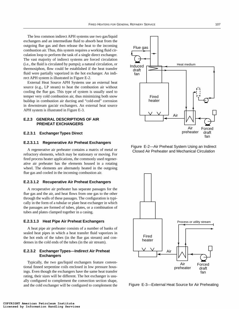
FIRED HEATERS FOR GENERAL REFINERY SERVICE 107
The less common indirect APH systems use two gas/liquidexchangers and an intermediate fluid to absorb heat from theoutgoing flue gas and then release the heat to the incomingcombustion air. Thus, this system requires a working fluid cir-culation loop to perform the task of a single direct exchanger.The vast majority of indirect systems are forced circulation(i.e., the fluid is circulated by pumps); a natural circulation, orthermosiphon, flow could be established if the heat transferfluid were partially vaporized in the hot exchanger. An indi-rect APH system is illustrated in Figure E-2.
External Heat Source APH Systems use an external heatsource (e.g., LP steam) to heat the combustion air withoutcooling the flue gas. This type of system is usually used totemper very cold combustion air, thus minimizing both snowbuildup in combustion air ducting and “cold-end” corrosionin downstream gas/air exchangers. An external heat sourceAPH system is illustrated in Figure E-3.
E.2.3 GENERAL DESCRIPTIONS OF AIR PREHEAT EXCHANGERS
E.2.3.1 Exchanger Types Direct
E.2.3.1.1 Regenerative Air Preheat Exchangers
A regenerative air preheater contains a matrix of metal orrefractory elements, which may be stationary or moving. Forfired process heater applications, the commonly used regener-ative air preheater has the elements housed in a rotatingwheel. The elements are alternately heated in the outgoingflue gas and cooled in the incoming combustion air.
E.2.3.1.2 Recuperative Air Preheat Exchangers
A recuperative air preheater has separate passages for theflue gas and the air, and heat flows from one gas to the otherthrough the walls of these passages. The configuration is typi-cally in the form of a tubular or plate heat exchanger in whichthe passages are formed of tubes, plates, or a combination oftubes and plates clamped together in a casing.
E.2.3.1.3 Heat Pipe Air Preheat Exchangers
A heat pipe air preheater consists of a number of banks ofsealed heat pipes in which a heat transfer fluid vaporizes inthe hot ends of the tubes (in the flue gas stream) and con-denses in the cold ends of the tubes (in the air stream).
E.2.3.2 Exchanger Types—Indirect Air Preheat Exchangers
Typically, the two gas/liquid exchangers feature conven-tional finned serpentine coils enclosed in low pressure hous-ings. Even though the exchangers have the same heat transferrating, their sizes will be different. The hot exchanger is usu-ally configured to complement the convection section shape,and the cold exchanger will be configured to complement the
Figure E-2—Air Preheat System Using an Indirect Closed Air Preheater and Mechanical Circulation
Figure E-3—External Heat Source for Air Preheating
Firedheater
Induceddraftfan
Flue gas
Air
Airpreheater
Forceddraftfan
Heat medium
Firedheater
Air
Airpreheater
Forceddraftfan
Process or utility stream
COPYRIGHT American Petroleum InstituteLicensed by Information Handling ServicesCOPYRIGHT American Petroleum InstituteLicensed by Information Handling Services
108 API STANDARD 560
E.2.3.3 Exchanger Types—External Heat Source Air Preheat Exchangers
External heat source exchangers are usually steam con-densing or liquid/gas designs. Because of their need to oper-ate in very cold climates, the exchangers usually feature fullydrainable coils. The common steam condensing preheatexchanger will have a small diameter, multiple pass, verticalfinned tube coil that is configured to complement the sur-rounding air ducting.
E.2.4 SYSTEM SELECTION CONSIDERATIONS
The following factors should be considered in the determi-nation of the most appropriate air preheat system design andthe selection of the APH exchanger type:
a. The heater’s natural draft operating requirements.
b. The available plot area for the APH system.
c. The heater’s fuel(s) and corresponding cleaningrequirements.
d. The APH system’s design flue gas temperatures.
e. The ability to clean the preheat exchanger with minimalimpact on the heater’s operations.
f. The ability to service the APH system with minimalimpact on the heater’s operations.
g. The negative effects of air leakage into the flue gas stream:corrosion of downstream equipment, increased hydraulichorsepower consumption, and reduced combustion air flow(which could cause a reduction in the heater’s firing rate).
h. The ability to provide uniform radiant flux via properburner location and arrangement.
i. The potential constraints of an exchanger’s maximumexposure temperatures.
j. The potential for, and methods available to minimize, coldend corrosion.
k. The system’s controls requirements and degree ofautomation.
l. The negative effects of heat transfer fluid leakage.
m. The effect of process terminal temperatures on the avail-able system efficiency.
n. The effect of burner type (forced versus natural draft).
o. The feasibility of enlarging the air preheat system capacityto handle future increases in process requirements.
E.3 Design ConsiderationsE.3.1 PROCESS DESIGN
The interaction of an air preheat system with a firedheater is, in process terms, particularly important in the case
of a retrofit, but the same considerations apply in the case ofa new installation.
If an existing heater, with unaltered radiant heat transfersurface, is to be retrofitted with an air preheat system and yetperform the same duty, the bridgewall temperature and theaverage radiant flux will be increased. A process designreview should be carried out to ascertain the heater’s air pre-heat operating conditions, and revised data sheets should beprepared that reflect these new design conditions. During thisprocess design effort, the design excess air and radiation lossvalues should be reviewed.
In some cases, the efficiency of an existing heater is so lowthat the addition of an air preheat system would generateother problems. Examples of such problems are:
a. The hot air temperature must be limited to control NOxemissions.
b. The hot air temperature must be limited to control highradiant flux rates (i.e., high tube metal temperatures).
c. The hot air temperature must be limited to control tubesupport and/or guide temperatures.
d. The air preheater selected cannot tolerate the high flue gastemperatures leaving the heater.
In many applications, any/all of the above problems maybe solved by adding convection section surface area, thusreducing the outlet flue gas temperature to an acceptablelevel.
E.3.2 COMBUSTION DESIGN
E.3.2.1 Burner Performance
The following objectives should be considered in theselection of burners for systems with, and without, APHsystems.
a. Maximum combustion performance throughout theentire operating range (inclusive of turndown) for all speci-fied fuels.
b. Maximum flux uniformity; identical heat release rates,identical flame shape/size, identical excess air percentagesthrough each and every burner.
c. Maximum burner-to-tube spacing (i.e., in excess of thatrequired to avoid flame impingement).
d. Minimum flue gas (NOx, CO, UHC, VOC, SPM)emissions.
e. Minimum noise emissions.
Note that the above selection criteria are applicable forboth natural draft and balanced/forced/induced draft (asapplicable) operations.
COPYRIGHT American Petroleum InstituteLicensed by Information Handling ServicesCOPYRIGHT American Petroleum InstituteLicensed by Information Handling Services

FIRED HEATERS FOR GENERAL REFINERY SERVICE 109
E.3.2.2 Burner Selection
The following general comments are meant to provide onlyan overview of the different burner designs commonly used infired heater applications. For a complete review of this topic,refer to API Publication 535; Burners for Fired Heaters inGeneral Refinery Services.
Burners are broadly categorized by draft and/or by com-bustion process. By draft, the two types are natural draft andforced draft. By combustion process, the most commonburner types are premix, raw gas/oil, staged air, staged fuel,and internal recirculation.
Because forced draft burners are dependent upon a fan toprovide a pressurized combustion air stream, the most com-mon burner type is natural draft. Natural draft burners havelow draft loss (< 20 mm H2O or 0.8 in. H2O) requirements,and are designed to operate with the draft created by the stackand heater proper.
Because of the increased air side pressure drop andenhanced mixing, forced draft burners generally providecombustion performance that is superior to natural draftburner performance. Compared to natural draft burners,forced draft burners operate at reduced excess air levels, pro-vide more stable flames and more defined flames.
The selection of burner type, by combustion process,depends on many factors. For a thorough discussion on thesemany factors, the reader should refer to the aforementionedAPI Publication 535.
E.3.2.3 Design Excess Air Percentages
An important consideration in maximizing a fired heater’sefficiency is the control of combustion air flow rates suchthat design excess air (or excess O2) levels are maintained,while sustaining complete combustion, stable and well-defined flames, and stable heater operation. Forced and bal-anced draft APH systems are able to operate at excess airlevels lower than natural draft systems. Typically, duringforced/balanced draft operation, a system can safely operatewith 5% less excess air than during natural draft operation.This excess air reduction is the result of the improved com-bustion air control provided by the typical forced draft fanand supporting instrumentation.
The design excess air percentages are usually slightlyreduced in retrofit applications. This reflects the superior air/fuel ratio control provided by the forced draft system. How-ever, excess air levels for retrofit efforts on “existing” heaters,that suffer from significant air infiltration, should not be mini-mized. Care should be exercised in such applications to esti-mate the burner excess air by subtracting the estimated airleakage percentage from the measured heater excess air per-centage. A superior alternative is to repair, fill and caulk leak-ing areas.
It is a common oversight to overlook the leakage air. It isinappropriate to assume that the excess air concentrationmeasured at the arch/roof is the actual burner excess air con-centration. Following are expected design excess air levels forgeneral service “air tight” fired heaters.
E.3.2.3.1 Natural Draft Burners
a. Fuel gas fired, Natural Draft Operation; 15%.
b. Fuel gas fired, Forced/Balanced Draft Operation; 10%.
c. Fuel oil fired, Natural Draft Operation; 20%.
d. Fuel oil fired, Forced/Balanced Draft Operation; 15%.
E.3.2.3.2 Forced Draft Burners
a. Fuel gas fired, Forced/Balanced Draft Operation; 10%.
b. Fuel oil fired, Forced/Balanced Draft Operation; 15%.
The above percentages are desired operating excess air lev-els. Where the heater design and/or user experience dictates,otherwise, it will be appropriate to design the system to oper-ate at different excess air levels.
E.3.2.4 Setting Losses
To accurately reflect the additional surface area of the APHsystem’s hot ducts, it is usually appropriate to increase theheater’s setting losses by 0.50 to 1.00%, to a total of 2.0 to2.5%.
E.3.2.5 High Air Temperature Considerations
High flue gas temperatures will often result in high com-bustion air temperatures. If the air preheater will generatehigh air temperatures, the burners and similar componentsdownstream of the APH exchanger may need to be con-structed of higher chrome alloys and/or have enhanceddesigns. The increased combustion air temperatures willincrease the burners’ flame temperatures, consequentlyincreasing the burners’ thermal NOx production. If a NOxemissions target cannot be achieved at the current design con-ditions, one or more of the following solutions must be con-sidered:
a. Change the burner design.
b. Reduce the combustion air temperature.
c. Reduce the firebox temperature (i.e., bridgewalltemperature).
d. Change the fuel(s) compositions to achieve lower temper-ature flames.
e. Retrofit a post-combustion NOx reduction (e.g., SCR orSNCR) system to the heater.
COPYRIGHT American Petroleum InstituteLicensed by Information Handling ServicesCOPYRIGHT American Petroleum InstituteLicensed by Information Handling Services
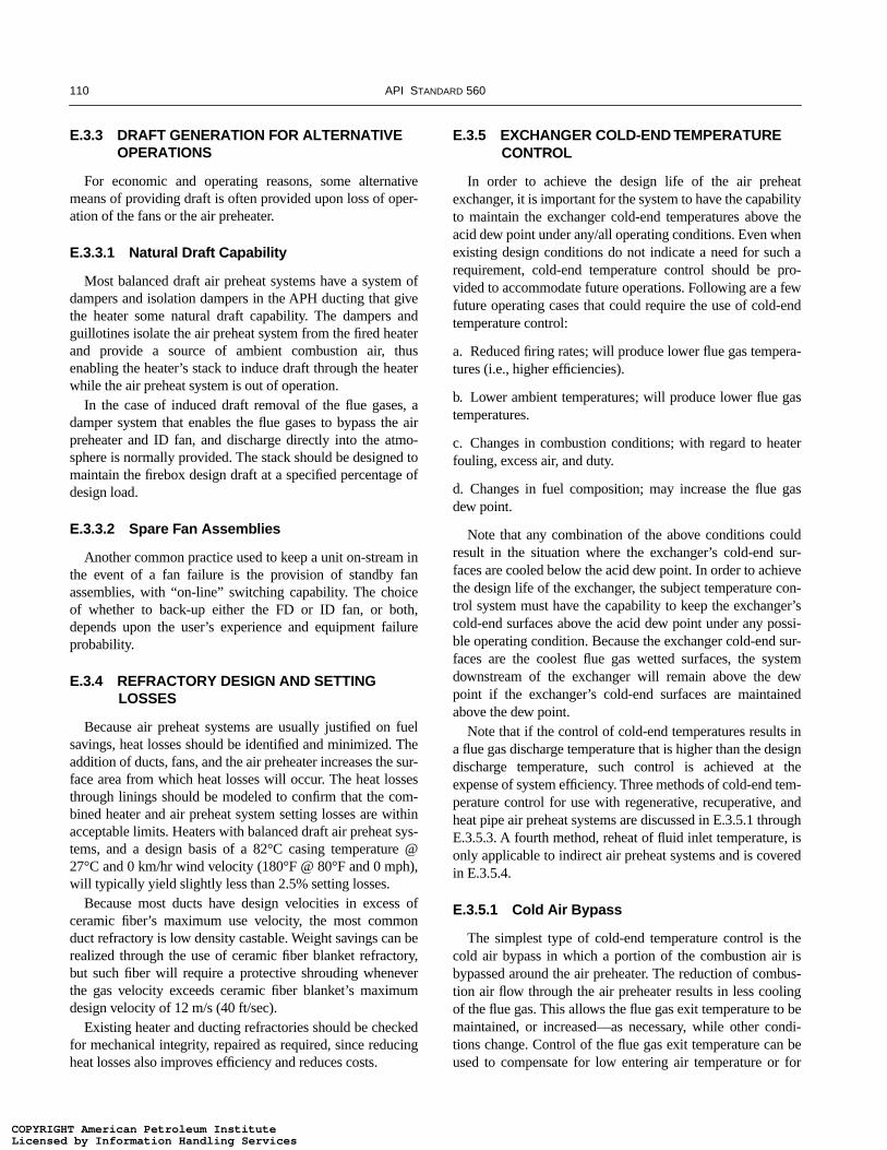
110 API STANDARD 560
E.3.3 DRAFT GENERATION FOR ALTERNATIVE OPERATIONS
For economic and operating reasons, some alternativemeans of providing draft is often provided upon loss of oper-ation of the fans or the air preheater.
E.3.3.1 Natural Draft Capability
Most balanced draft air preheat systems have a system ofdampers and isolation dampers in the APH ducting that givethe heater some natural draft capability. The dampers andguillotines isolate the air preheat system from the fired heaterand provide a source of ambient combustion air, thusenabling the heater’s stack to induce draft through the heaterwhile the air preheat system is out of operation.
In the case of induced draft removal of the flue gases, adamper system that enables the flue gases to bypass the airpreheater and ID fan, and discharge directly into the atmo-sphere is normally provided. The stack should be designed tomaintain the firebox design draft at a specified percentage ofdesign load.
E.3.3.2 Spare Fan Assemblies
Another common practice used to keep a unit on-stream inthe event of a fan failure is the provision of standby fanassemblies, with “on-line” switching capability. The choiceof whether to back-up either the FD or ID fan, or both,depends upon the user’s experience and equipment failureprobability.
E.3.4 REFRACTORY DESIGN AND SETTING LOSSES
Because air preheat systems are usually justified on fuelsavings, heat losses should be identified and minimized. Theaddition of ducts, fans, and the air preheater increases the sur-face area from which heat losses will occur. The heat lossesthrough linings should be modeled to confirm that the com-bined heater and air preheat system setting losses are withinacceptable limits. Heaters with balanced draft air preheat sys-tems, and a design basis of a 82°C casing temperature @27°C and 0 km/hr wind velocity (180°F @ 80°F and 0 mph),will typically yield slightly less than 2.5% setting losses.
Because most ducts have design velocities in excess ofceramic fiber’s maximum use velocity, the most commonduct refractory is low density castable. Weight savings can berealized through the use of ceramic fiber blanket refractory,but such fiber will require a protective shrouding wheneverthe gas velocity exceeds ceramic fiber blanket’s maximumdesign velocity of 12 m/s (40 ft/sec).
Existing heater and ducting refractories should be checkedfor mechanical integrity, repaired as required, since reducingheat losses also improves efficiency and reduces costs.
E.3.5 EXCHANGER COLD-END TEMPERATURE CONTROL
In order to achieve the design life of the air preheatexchanger, it is important for the system to have the capabilityto maintain the exchanger cold-end temperatures above theacid dew point under any/all operating conditions. Even whenexisting design conditions do not indicate a need for such arequirement, cold-end temperature control should be pro-vided to accommodate future operations. Following are a fewfuture operating cases that could require the use of cold-endtemperature control:
a. Reduced firing rates; will produce lower flue gas tempera-tures (i.e., higher efficiencies).
b. Lower ambient temperatures; will produce lower flue gastemperatures.
c. Changes in combustion conditions; with regard to heaterfouling, excess air, and duty.
d. Changes in fuel composition; may increase the flue gasdew point.
Note that any combination of the above conditions couldresult in the situation where the exchanger’s cold-end sur-faces are cooled below the acid dew point. In order to achievethe design life of the exchanger, the subject temperature con-trol system must have the capability to keep the exchanger’scold-end surfaces above the acid dew point under any possi-ble operating condition. Because the exchanger cold-end sur-faces are the coolest flue gas wetted surfaces, the systemdownstream of the exchanger will remain above the dewpoint if the exchanger’s cold-end surfaces are maintainedabove the dew point.
Note that if the control of cold-end temperatures results ina flue gas discharge temperature that is higher than the designdischarge temperature, such control is achieved at theexpense of system efficiency. Three methods of cold-end tem-perature control for use with regenerative, recuperative, andheat pipe air preheat systems are discussed in E.3.5.1 throughE.3.5.3. A fourth method, reheat of fluid inlet temperature, isonly applicable to indirect air preheat systems and is coveredin E.3.5.4.
E.3.5.1 Cold Air Bypass
The simplest type of cold-end temperature control is thecold air bypass in which a portion of the combustion air isbypassed around the air preheater. The reduction of combus-tion air flow through the air preheater results in less coolingof the flue gas. This allows the flue gas exit temperature to bemaintained, or increased—as necessary, while other condi-tions change. Control of the flue gas exit temperature can beused to compensate for low entering air temperature or for
COPYRIGHT American Petroleum InstituteLicensed by Information Handling ServicesCOPYRIGHT American Petroleum InstituteLicensed by Information Handling Services

FIRED HEATERS FOR GENERAL REFINERY SERVICE 111
increased sulfur trioxide concentration (i.e., higher flue gasdew point temperature).
E.3.5.2 External Preheat of Cold Air
In this system, the desired cold-end metal temperature ismaintained by heating the combustion air, before it enters theair preheater, with low pressure steam or some other source oflow level heat. Consideration must be given to preventingfouling and plugging of the low-level heat unit with atmo-spheric dust that may be entrained in the combustion air andto preventing freeze-up of the coil in cold weather.
E.3.5.3 Recirculation of Hot Air
This system recycles heated combustion air to the FD fansuction to obtain a mixed air temperature that is highenough to keep the exchanger cold-end above the dew pointtemperature.
E.3.5.4 Reheat Fluid Inlet Temperature Control
In the circulating fluid or once through air preheat systems,the exchanger cold-end temperatures can be regulated by con-trolling the inlet temperature of the heat transfer fluid.Depending on the system design and configuration, the reheatfluid temperature is increased either by bypassing a portion ofthe fluid around the air heating coil or by decreasing thereheat fluid flow rate.
E.3.6 STACK TEMPERATURE CONTROL
In most applications, the primary emphasis of cold-endtemperature control is directed at the temperatures of the heattransfer surfaces in the flue gas stream. These surfaces aregenerally lower in temperature than the surfaces of down-stream equipment such as the draft fan and stack. In addition,an APH system design typically makes provisions for “winteroperating conditions”. The system should provide the meansfor measuring and controlling the cold flue gas temperatureabove the acid dew point temperature. A recommended mini-mum metal temperature curve for surfaces exposed to flue gasis provided in Figure E-4. Any of the four methods to controlcold end temperatures (see E.3.5.1 through E.3.5.4) may alsobe used to control the stack temperature.
The design, maintenance and operation of an APH systemshould minimize cold air leakage, insulation voids, and othersources of localized cooling that could result in localized cor-rosion in the cold flue gas section of the system.
E.3.7 EXCHANGER MECHANICAL DESIGN
E.3.7.1 Regenerative Air Preheaters
The cold-end heat transfer surfaces of a regenerative airpreheater are not required to serve as pressure parts confining
a fluid, are designed to accommodate moderate corrosion,and should be replaced periodically. As a result, regenerativeair preheaters may operate at lower metal temperatures thanmost other types of air preheaters. However, considerationmust be given to effects on downstream equipment of theinherent air leakage and the periodic removal of acidic sootparticles during sootblowing.
Regenerative air preheaters are commercially available instandard combinations of carbon steel, low-alloy steel, andcorrosion-resistant enameled steel construction. The manu-facturer should be consulted for recommended cold-end tem-perature limits.
E.3.7.2 Recuperative Air Preheaters
Recuperative air preheaters are commercially availablewith carbon steel, cast iron, enameled steel and glass ele-ments. The finning normally provided in the cast iron con-struction may be modified on the air side of the cold-endelements to increase the metal temperatures.
Units equipped with enameled steel or glass elementswill accommodate moderate acid condensation and fouling,but consideration must be given to requirements for theremoval of deposits by sootblowing and for water washingwithout adversely affecting downstream equipment. In addi-tion, the risk of breaking glass elements, particularly duringcleaning operations, must be considered. The exchangermanufacturer should be consulted for recommended waterwash temperature, minimum cold-end temperatures andmaterials of construction.
E.3.7.3 Indirect Systems
The heat transfer surfaces exposed to the fired heater fluegas in indirect systems are generally similar in construction toand located in the fired heater convection section. The serviceand construction of these coils make corrosion and foulingvery undesirable.
Cold-end temperatures should be selected so that coilsalways operate with metal temperatures above the flue gasdew point. A recommended minimum metal temperaturecurve is shown in Figure E-4. In APH system retrofit applica-tions, design reviews should be carried out on the heater’smechanical components to:
a. Determine if mechanical components are suitable for thenew conditions.
b. Determine if significant deterioration has taken place.
c. Consider changes in design codes that may have takenplace since the original heater was designed and installed.
Components that may be affected by these checks includetube supports and guides.
COPYRIGHT American Petroleum InstituteLicensed by Information Handling ServicesCOPYRIGHT American Petroleum InstituteLicensed by Information Handling Services

112 API STANDARD 560
E.4 Selection Guidelines
General considerations in the application of an air preheatsystem are presented in Section E.2. In contrast, this sectionprovides a more detailed review of each system’s characteris-tics that should be an aid in the understanding of strengthsand weaknesses of each system.
E.4.1 COMMON SELECTION CONSIDERATIONS
E.4.1.1 Plot Area
Plot area requirements are a function of the system typeand system layout. Balanced draft systems, with grademounted fans and an independent exchanger structure, willrequire the largest plot area. However, because of the abilityto isolate the exchanger and fans from the heater, this systemlayout provides the greatest operating flexibility and mainte-nance flexibility.
Forced draft systems, with a grade mounted fan and anintegral exchanger, will require significantly less plot area
than a balanced draft system. Because the exchanger islocated above the convection section, however, this systemtype does not permit the exchanger to be serviced while theheater is in operation.
Induced draft systems, with a grade mounted fan and anindependent exchanger structure, will require slightly lessplot area than the balanced draft system. However, becauseof the ability to isolate the exchanger and fan from theheater, this system layout provides the same operatingflexibility and maintenance flexibility as the balanced draftsystem.
Common practices to reduce the plot area include:
a. Locating the exchanger above the heater’s convectionsection.
b. Locating exchanger terminals such that duct connectionsare vertically oriented.
c. Stacking fans.
d. Using axial flow fans.
Figure E-4—Recommended Minimum Metal Temperature
350
Met
al T
empe
ratu
re, °
F
300
1.0 2.0 3.0 4.0 5.0 6.0150
200
250
Weight Percent Sulfur in Fuel
Recommended minimum metal temperaturefor convection coils, fans, and duct steelexposed to flue gas.
COPYRIGHT American Petroleum InstituteLicensed by Information Handling ServicesCOPYRIGHT American Petroleum InstituteLicensed by Information Handling Services
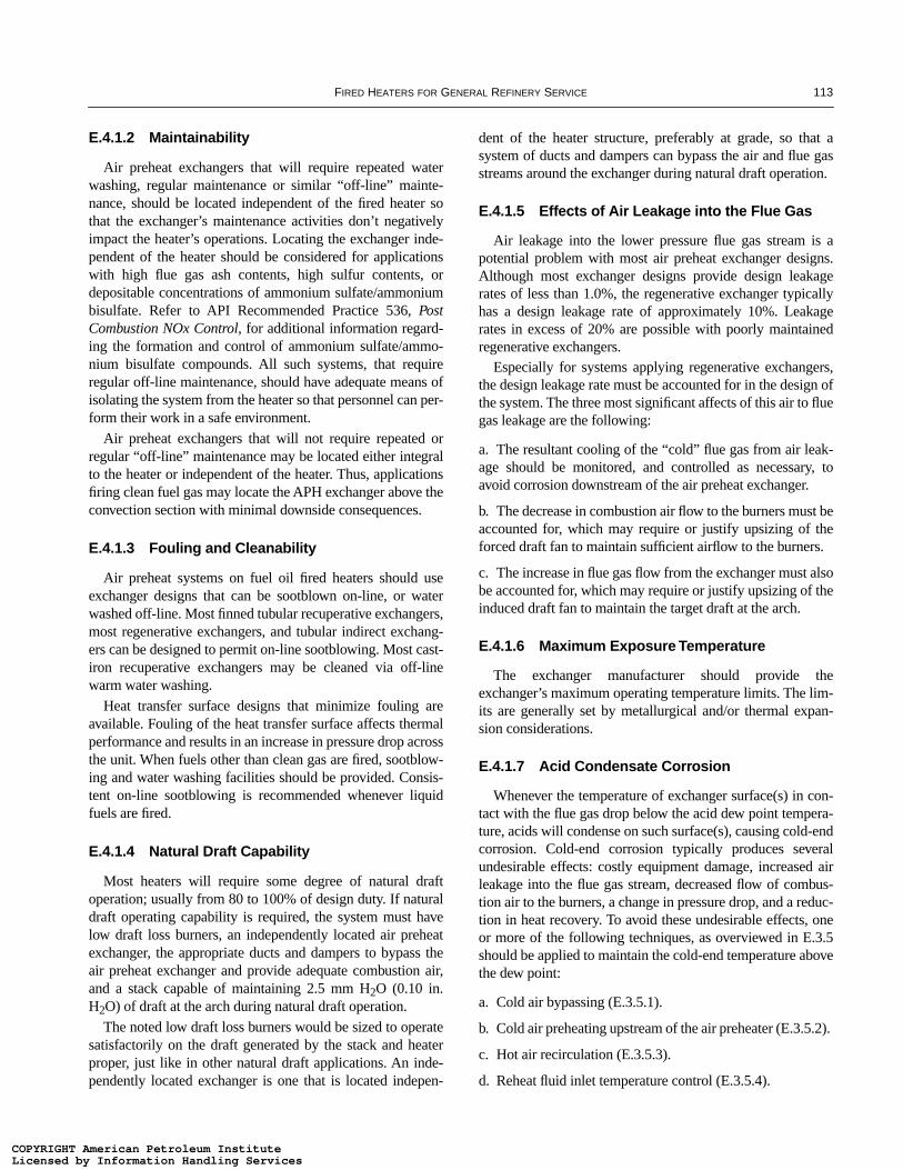
FIRED HEATERS FOR GENERAL REFINERY SERVICE 113
E.4.1.2 Maintainability
Air preheat exchangers that will require repeated waterwashing, regular maintenance or similar “off-line” mainte-nance, should be located independent of the fired heater sothat the exchanger’s maintenance activities don’t negativelyimpact the heater’s operations. Locating the exchanger inde-pendent of the heater should be considered for applicationswith high flue gas ash contents, high sulfur contents, ordepositable concentrations of ammonium sulfate/ammoniumbisulfate. Refer to API Recommended Practice 536, PostCombustion NOx Control, for additional information regard-ing the formation and control of ammonium sulfate/ammo-nium bisulfate compounds. All such systems, that requireregular off-line maintenance, should have adequate means ofisolating the system from the heater so that personnel can per-form their work in a safe environment.
Air preheat exchangers that will not require repeated orregular “off-line” maintenance may be located either integralto the heater or independent of the heater. Thus, applicationsfiring clean fuel gas may locate the APH exchanger above theconvection section with minimal downside consequences.
E.4.1.3 Fouling and Cleanability
Air preheat systems on fuel oil fired heaters should useexchanger designs that can be sootblown on-line, or waterwashed off-line. Most finned tubular recuperative exchangers,most regenerative exchangers, and tubular indirect exchang-ers can be designed to permit on-line sootblowing. Most cast-iron recuperative exchangers may be cleaned via off-linewarm water washing.
Heat transfer surface designs that minimize fouling areavailable. Fouling of the heat transfer surface affects thermalperformance and results in an increase in pressure drop acrossthe unit. When fuels other than clean gas are fired, sootblow-ing and water washing facilities should be provided. Consis-tent on-line sootblowing is recommended whenever liquidfuels are fired.
E.4.1.4 Natural Draft Capability
Most heaters will require some degree of natural draftoperation; usually from 80 to 100% of design duty. If naturaldraft operating capability is required, the system must havelow draft loss burners, an independently located air preheatexchanger, the appropriate ducts and dampers to bypass theair preheat exchanger and provide adequate combustion air,and a stack capable of maintaining 2.5 mm H2O (0.10 in.H2O) of draft at the arch during natural draft operation.
The noted low draft loss burners would be sized to operatesatisfactorily on the draft generated by the stack and heaterproper, just like in other natural draft applications. An inde-pendently located exchanger is one that is located indepen-
dent of the heater structure, preferably at grade, so that asystem of ducts and dampers can bypass the air and flue gasstreams around the exchanger during natural draft operation.
E.4.1.5 Effects of Air Leakage into the Flue Gas
Air leakage into the lower pressure flue gas stream is apotential problem with most air preheat exchanger designs.Although most exchanger designs provide design leakagerates of less than 1.0%, the regenerative exchanger typicallyhas a design leakage rate of approximately 10%. Leakagerates in excess of 20% are possible with poorly maintainedregenerative exchangers.
Especially for systems applying regenerative exchangers,the design leakage rate must be accounted for in the design ofthe system. The three most significant affects of this air to fluegas leakage are the following:
a. The resultant cooling of the “cold” flue gas from air leak-age should be monitored, and controlled as necessary, toavoid corrosion downstream of the air preheat exchanger.
b. The decrease in combustion air flow to the burners must beaccounted for, which may require or justify upsizing of theforced draft fan to maintain sufficient airflow to the burners.
c. The increase in flue gas flow from the exchanger must alsobe accounted for, which may require or justify upsizing of theinduced draft fan to maintain the target draft at the arch.
E.4.1.6 Maximum Exposure Temperature
The exchanger manufacturer should provide theexchanger’s maximum operating temperature limits. The lim-its are generally set by metallurgical and/or thermal expan-sion considerations.
E.4.1.7 Acid Condensate Corrosion
Whenever the temperature of exchanger surface(s) in con-tact with the flue gas drop below the acid dew point tempera-ture, acids will condense on such surface(s), causing cold-endcorrosion. Cold-end corrosion typically produces severalundesirable effects: costly equipment damage, increased airleakage into the flue gas stream, decreased flow of combus-tion air to the burners, a change in pressure drop, and a reduc-tion in heat recovery. To avoid these undesirable effects, oneor more of the following techniques, as overviewed in E.3.5should be applied to maintain the cold-end temperature abovethe dew point:
a. Cold air bypassing (E.3.5.1).
b. Cold air preheating upstream of the air preheater (E.3.5.2).
c. Hot air recirculation (E.3.5.3).
d. Reheat fluid inlet temperature control (E.3.5.4).
COPYRIGHT American Petroleum InstituteLicensed by Information Handling ServicesCOPYRIGHT American Petroleum InstituteLicensed by Information Handling Services
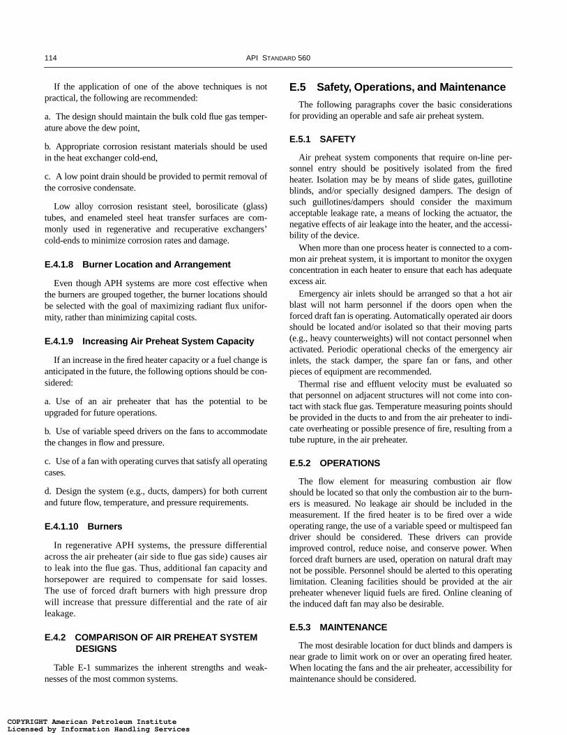
114 API STANDARD 560
If the application of one of the above techniques is notpractical, the following are recommended:
a. The design should maintain the bulk cold flue gas temper-ature above the dew point,
b. Appropriate corrosion resistant materials should be usedin the heat exchanger cold-end,
c. A low point drain should be provided to permit removal ofthe corrosive condensate.
Low alloy corrosion resistant steel, borosilicate (glass)tubes, and enameled steel heat transfer surfaces are com-monly used in regenerative and recuperative exchangers’cold-ends to minimize corrosion rates and damage.
E.4.1.8 Burner Location and Arrangement
Even though APH systems are more cost effective whenthe burners are grouped together, the burner locations shouldbe selected with the goal of maximizing radiant flux unifor-mity, rather than minimizing capital costs.
E.4.1.9 Increasing Air Preheat System Capacity
If an increase in the fired heater capacity or a fuel change isanticipated in the future, the following options should be con-sidered:
a. Use of an air preheater that has the potential to beupgraded for future operations.
b. Use of variable speed drivers on the fans to accommodatethe changes in flow and pressure.
c. Use of a fan with operating curves that satisfy all operatingcases.
d. Design the system (e.g., ducts, dampers) for both currentand future flow, temperature, and pressure requirements.
E.4.1.10 Burners
In regenerative APH systems, the pressure differentialacross the air preheater (air side to flue gas side) causes airto leak into the flue gas. Thus, additional fan capacity andhorsepower are required to compensate for said losses.The use of forced draft burners with high pressure dropwill increase that pressure differential and the rate of airleakage.
E.4.2 COMPARISON OF AIR PREHEAT SYSTEM DESIGNS
Table E-1 summarizes the inherent strengths and weak-nesses of the most common systems.
E.5 Safety, Operations, and Maintenance
The following paragraphs cover the basic considerationsfor providing an operable and safe air preheat system.
E.5.1 SAFETY
Air preheat system components that require on-line per-sonnel entry should be positively isolated from the firedheater. Isolation may be by means of slide gates, guillotineblinds, and/or specially designed dampers. The design ofsuch guillotines/dampers should consider the maximumacceptable leakage rate, a means of locking the actuator, thenegative effects of air leakage into the heater, and the accessi-bility of the device.
When more than one process heater is connected to a com-mon air preheat system, it is important to monitor the oxygenconcentration in each heater to ensure that each has adequateexcess air.
Emergency air inlets should be arranged so that a hot airblast will not harm personnel if the doors open when theforced draft fan is operating. Automatically operated air doorsshould be located and/or isolated so that their moving parts(e.g., heavy counterweights) will not contact personnel whenactivated. Periodic operational checks of the emergency airinlets, the stack damper, the spare fan or fans, and otherpieces of equipment are recommended.
Thermal rise and effluent velocity must be evaluated sothat personnel on adjacent structures will not come into con-tact with stack flue gas. Temperature measuring points shouldbe provided in the ducts to and from the air preheater to indi-cate overheating or possible presence of fire, resulting from atube rupture, in the air preheater.
E.5.2 OPERATIONS
The flow element for measuring combustion air flowshould be located so that only the combustion air to the burn-ers is measured. No leakage air should be included in themeasurement. If the fired heater is to be fired over a wideoperating range, the use of a variable speed or multispeed fandriver should be considered. These drivers can provideimproved control, reduce noise, and conserve power. Whenforced draft burners are used, operation on natural draft maynot be possible. Personnel should be alerted to this operatinglimitation. Cleaning facilities should be provided at the airpreheater whenever liquid fuels are fired. Online cleaning ofthe induced daft fan may also be desirable.
E.5.3 MAINTENANCE
The most desirable location for duct blinds and dampers isnear grade to limit work on or over an operating fired heater.When locating the fans and the air preheater, accessibility formaintenance should be considered.
COPYRIGHT American Petroleum InstituteLicensed by Information Handling ServicesCOPYRIGHT American Petroleum InstituteLicensed by Information Handling Services

FIRED HEATERS FOR GENERAL REFINERY SERVICE 115
E.5.4 PERFORMANCE CHECKS
The following APH system features are recommended:
a. Temperature and pressure measuring connections in allflue gas and air streams entering and leaving the air preheater(to monitor performance and fouling),
b. Pressure measuring connections at locations upstream anddownstream of the fan(s),
c. Flue gas analyzer connections—for continuous gas analy-sis—upstream of the exchanger, unless such connectionswould be redundant,
d. Flue gas sample connections—for occasional use—imme-diately upstream and immediately downstream of the airpreheat exchanger (to monitor leakage),
e. Pitot Tube ports immediately upstream of the APHexchanger in the flue gas and air streams to allow themeasurement and troubleshooting of the air and flue gasflow profiles entering the exchanger. APH system perfor-mance will be adversely affected by air and/or gasmaldistribution.
E.5.5 AIR PREHEAT SYSTEM EQUIPMENT FAILURE
It is usually cost effective to provide provisions for a “sec-ondary,” or fail-safe, mode of heater operation. Thus, in mostapplications, the air preheat system is designed to permit sta-ble fired heater operation whenever the preheat system expe-riences a mechanical failure. The two most commonsecondary operating modes are the following:
a. Bypassing the air preheat system and defaulting to naturaldraft operation,
b. Activating a spare fan(s).
The APH system should have the means to confirm thatsuch a change has been safely and successfully executed.Refer to Sections E.3.2, E.3.3, and E.4.1.4 for additionalguidelines for natural draft operations.
E.6 Exchanger Performance GuidelinesE.6.1 INTRODUCTION
The common design objective of most air preheat systemsis to maximize the fired heater’s efficiency consistent with the
Table E-1—Comparisons of Various Air Preheat Systems
Regenerative Recuperative Heat Pipe Indirect E.H.S
Characteristic units F.D. B.D. F.D. I.D. B.D. F.D. I.D. B.D. F.D. B.D. F.D.
Plot Area s,m,l — m s m l s m l l l m
HX Location int,ind int sep int sep sep int sep sep int&sep sep sep
Capital Costs l,m,h m h m m h m m h m h l
Operating Costs l,m,h m h l m h l m h m h l
Maintenance Costs l,m,h h h l m m l m m l m l
Online Cleaning y or n n y y/n y y n y y y y y
Online Maintenance y or n n y n y y n y y n y y
Qty. of Rotating Equipment no. 2 3 1 1 2 1 1 2 2 3 1
Design Leakage % 10 10 <1.0 <1.0 <1.0 <1.0 <1.0 <1.0 0.0 0.0 0.0
Leakage Potential y or n y y y y y y y y n n n
Fire Potential y or n y y n n n n n n n n n
Comparison Table Key:Area s = small, m = medium, and l = large area requirementsLocation int = integral to heater structure, ind = independent of heater structureCosts l = low, m = medium, and h = highCleaning y = yes and n = noMaintenance y = yes and n = noQty Rotating quantity of rotating equipment assemblies that must be operated/maintainedDesign Leakage Design leakage (air to flue gas) percentageLeakage y = yes and n = noFire y = yes and n = no
COPYRIGHT American Petroleum InstituteLicensed by Information Handling ServicesCOPYRIGHT American Petroleum InstituteLicensed by Information Handling Services

116 API STANDARD 560
system’s capital, operating, and maintenance costs. Toachieve this objective, it is important to select a cold-enddesign (flue gas) temperature that maximizes flue gas heatrecovery and minimizes fouling and corrosion. The flue gastemperature at which corrosion and fouling become excessiveis affected by:
a. Fuel sulfur or other contaminant content.
b. Fuel or flue gas additives.
c. Flue gas oxygen and moisture content.
d. Combustion temperature.
e. Furnace cleanliness.
f. Burner design.
g. Air preheater design.
h. Ash content from heavy residual oils.
E.6.2 SELECTING COLD-END TEMPERATURES
E.6.2.1 Recommended Minimum Metal Temperatures
Corrosion of air preheater cold-end surfaces is generallycaused by the condensation of sulfuric acid vapor formedfrom the products of combustion of a sulfur laden fuel. Theacidic deposits also provides a moist surface that is ideal forcollecting particles that foul the air preheater heat transfersurface. Consequently, to obtain the normal design life from apreheat exchanger, it is imperative to operate the system in amanner that keeps the air preheater’s surfaces above the aciddew point temperature.
Figure E-4 provides a recommended minimum metal tem-perature (vs. fuel sulfur content) curve for flue gas wetted sur-faces. Any of the four methods presented in Section E.3 (seeE.3.5.1 through E.3.5.4) may be used to control theexchanger cold-end temperatures. Appendix F-A includes abibliography and a summary of some of the significant testwork reported in the literature.
E.6.2.2 Recommended Minimum Flue Gas Temperatures
Typically, APH exchanger design engineers will directlycalculate the minimum cold-end metal temperature; thus,negating the need for a minimum flue gas temperature alto-gether. However, for technical staff that are unable to calcu-late the minimum metal temperature, another method to setthe exchanger’s operating parameters is to obtain the afore-mentioned minimum metal temperature and add a small tem-perature allowance to obtain the minimum flue gastemperature. Temperature allowances of only 8–14°C (15–25°F) are typical.
E.6.2.3 Flue Gas Dew Point Monitoring
For air preheat systems with the capacity for reducing thestack temperatures below the design temperature, a programof local, periodic flue gas dew point testing may offer consid-erable economic advantages. Dew point determinations canbe used as a guide for varying the cold-end temperatures. Itmust be recognized that the cold-end metal temperature issubstantially lower than the exit gas temperature so care mustbe exercised when exit gas temperature measurement is theonly measurement available.
E.6.3 SELECTING HOT-END TEMPERATURE
The hot flue gas temperature is a direct outcome of theheater design. Current heater designs will usually providethe following “process inlet-to-exit flue gas” approach dif-ferentials:
a. For A106 B ↔ T11/P11 materials: 40–80°C (75–150°F).
b. For T22/P22 ↔ T91/P91 materials: 70–110°C (125–200°F).
c. For T304 ↔ T347H materials: 80–140°C (150–250°F).
E.6.3.1 Regenerative Air Preheaters
Regenerative air preheaters are generally suitable for maxi-mum inlet flue gas temperatures up to 540°C (1,000°F). Byusing special materials and constructions, these air preheaterscan be designed for maximum flue gas temperatures up to680°C (1,250°F). The exchanger manufacturer should beconsulted for specific recommendations.
E.6.3.2 Recuperative Air Preheaters
The standard cast-iron recuperative air preheater is gener-ally suitable for maximum inlet flue gas temperatures up to540°C (1,000°F). By using special materials and construc-tions, these air preheaters can be designed for maximum fluegas temperatures up to 980°C (1,800°F). The exchanger man-ufacturer should be consulted for specific recommendations.
E.6.3.3 Indirect Systems
The coils of fluid systems, whether heat pipes or circulat-ing, must be designed to avoid degradation of the containedfluid. For heat transfer fluids, the manufacturer’s recommen-dation for the maximum film temperature should be followed.In the case of the heat pipe, the exchanger manufacturershould be consulted for specific recommendations.
E.7 Fan Sizing and Performance Guidelines
E.7.1 INTRODUCTION
All air preheat systems are dependent upon the properoperation of a fan, or fans, to overcome the draft losses (i.e.,
COPYRIGHT American Petroleum InstituteLicensed by Information Handling ServicesCOPYRIGHT American Petroleum InstituteLicensed by Information Handling Services
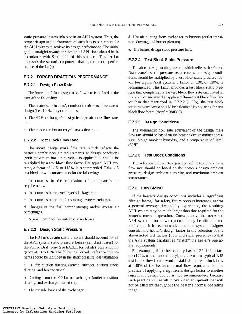
FIRED HEATERS FOR GENERAL REFINERY SERVICE 117
static pressure losses) inherent in an APH system. Thus, theproper design and performance of such fans is paramount forthe APH system to achieve its design performance. The initialgoal is straightforward: the design of APH fans should be inaccordance with Section 11 of this standard. This sectionaddresses the second component, that is, the proper perfor-mance of the fan(s).
E.7.2 FORCED DRAFT FAN PERFORMANCE
E.7.2.1 Design Flow Rate
The forced draft fan design mass flow rate is defined as thesum of the following:
a. The heater’s, or heaters’, combustion air mass flow rate atdesign (i.e., 100% duty) conditions,
b. The APH exchanger’s design leakage air mass flow rate,and
c. The maximum hot air recycle mass flow rate.
E.7.2.2 Test Block Flow Rate
The above design mass flow rate, which reflects theheater’s combustion air requirements at design conditions(with maximum hot air recycle—as applicable), should bemultiplied by a test block flow factor. For typical APH sys-tems, a factor of 1.15, or 115%, is recommended. This 1.15test block flow factor accounts for the following:
a. Inaccuracies in the calculation of the heater’s airrequirements.
b. Inaccuracies in the exchanger’s leakage rate.
c. Inaccuracies in the FD fan’s rating/sizing correlations.
d. Changes in the fuel composition(s) and/or excess airpercentages.
e. A small tolerance for unforeseen air losses.
E.7.2.3 Design Static Pressure
The FD fan’s design static pressure should account for allthe APH system static pressure losses (i.e., draft losses) forthe Forced Draft zone (see E.8.3.1. for details), plus a contin-gency of 10 to 15%. The following Forced Draft zone compo-nents should be included in the static pressure loss tabulation:
a. FD fan suction ducting (screen, silencer, suction stack,ducting, and fan transition).
b. Ducting from the FD fan to exchanger (outlet transition,ducting, and exchanger transition).
c. The air side losses of the exchanger.
d. Hot air ducting from exchanger to burners (outlet transi-tion, ducting, and burner plenum).
e. The burner design static pressure loss.
E.7.2.4 Test Block Static Pressure
The above design static pressure, which reflects the ForcedDraft zone’s static pressure requirements at design condi-tions, should be multiplied by a test block static pressure fac-tor. For typical APH systems a factor of 1.30, or 130%, isrecommended. This factor provides a test block static pres-sure that complements the test block flow rate calculated inE.7.2.2. For systems that apply a different test block flow fac-tor than that mentioned in E.7.2.2 (115%), the test blockstatic pressure factor should be calculated by squaring the testblock flow factor (tbspf = (tbff)^2).
E.7.2.5 Design Conditions
The volumetric flow rate equivalent of the design massflow rate should be based on the heater’s design ambient pres-sure, design ambient humidity, and a temperature of 16°C(60°F).
E.7.2.6 Test Block Conditions
The volumetric flow rate equivalent of the test block massflow rate should be based on the heater’s design ambientpressure, design ambient humidity, and maximum ambienttemperature.
E.7.3 FAN SIZING
If the heater’s design conditions includes a significant“design factor,” for safety, future process increases, and/ora general overage dictated by experience, the resultingAPH system may be much larger than that required for theheater’s normal operation. Consequently, the oversizedAPH system’s turndown operation may be difficult andinefficient. It is recommended that the system designerconsider the heater’s design factor in the selection of theabove noted test factors (flow and static pressure) so thatthe APH system capabilities “match” the heater’s operat-ing requirements.
For example, if the heater duty has a 1.20 design fac-tor (120% of the normal duty), the use of the typical 1.15test block flow factor would establish the test block flowat 138% of the heater’s normal flow requirements. Thepractice of applying a significant design factor to anothersignificant design factor is not recommended, becausesuch practice will result in oversized equipment that willnot be efficient throughout the heater’s normal operatingrange.
COPYRIGHT American Petroleum InstituteLicensed by Information Handling ServicesCOPYRIGHT American Petroleum InstituteLicensed by Information Handling Services
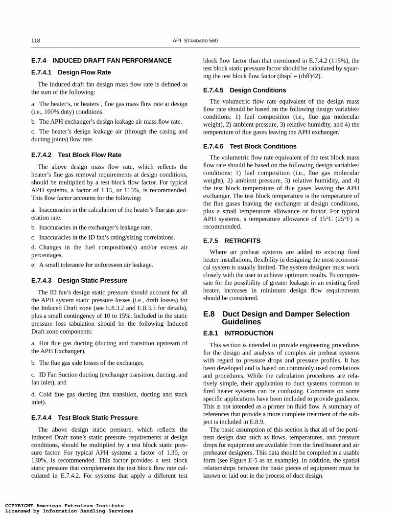
118 API STANDARD 560
E.7.4 INDUCED DRAFT FAN PERFORMANCE
E.7.4.1 Design Flow Rate
The induced draft fan design mass flow rate is defined asthe sum of the following:
a. The heater’s, or heaters’, flue gas mass flow rate at design(i.e., 100% duty) conditions.
b. The APH exchanger’s design leakage air mass flow rate.
c. The heater’s design leakage air (through the casing andducting joints) flow rate.
E.7.4.2 Test Block Flow Rate
The above design mass flow rate, which reflects theheater’s flue gas removal requirements at design conditions,should be multiplied by a test block flow factor. For typicalAPH systems, a factor of 1.15, or 115%, is recommended.This flow factor accounts for the following:
a. Inaccuracies in the calculation of the heater’s flue gas gen-eration rate.
b. Inaccuracies in the exchanger’s leakage rate.
c. Inaccuracies in the ID fan’s rating/sizing correlations.
d. Changes in the fuel composition(s) and/or excess airpercentages.
e. A small tolerance for unforeseen air leakage.
E.7.4.3 Design Static Pressure
The ID fan’s design static pressure should account for allthe APH system static pressure losses (i.e., draft losses) forthe Induced Draft zone (see E.8.3.2 and E.8.3.3 for details),plus a small contingency of 10 to 15%. Included in the staticpressure loss tabulation should be the following InducedDraft zone components:
a. Hot flue gas ducting (ducting and transition upstream ofthe APH Exchanger),
b. The flue gas side losses of the exchanger,
c. ID Fan Suction ducting (exchanger transition, ducting, andfan inlet), and
d. Cold flue gas ducting (fan transition, ducting and stackinlet).
E.7.4.4 Test Block Static Pressure
The above design static pressure, which reflects theInduced Draft zone’s static pressure requirements at designconditions, should be multiplied by a test block static pres-sure factor. For typical APH systems a factor of 1.30, or130%, is recommended. This factor provides a test blockstatic pressure that complements the test block flow rate cal-culated in E.7.4.2. For systems that apply a different test
block flow factor than that mentioned in E.7.4.2 (115%), thetest block static pressure factor should be calculated by squar-ing the test block flow factor (tbspf = (tbff)^2).
E.7.4.5 Design Conditions
The volumetric flow rate equivalent of the design massflow rate should be based on the following design variables/conditions: 1) fuel composition (i.e., flue gas molecularweight), 2) ambient pressure, 3) relative humidity, and 4) thetemperature of flue gases leaving the APH exchanger.
E.7.4.6 Test Block Conditions
The volumetric flow rate equivalent of the test block massflow rate should be based on the following design variables/conditions: 1) fuel composition (i.e., flue gas molecularweight), 2) ambient pressure, 3) relative humidity, and 4)the test block temperature of flue gases leaving the APHexchanger. The test block temperature is the temperature ofthe flue gases leaving the exchanger at design conditions,plus a small temperature allowance or factor. For typicalAPH systems, a temperature allowance of 15°C (25°F) isrecommended.
E.7.5 RETROFITS
Where air preheat systems are added to existing firedheater installations, flexibility in designing the most economi-cal system is usually limited. The system designer must workclosely with the user to achieve optimum results. To compen-sate for the possibility of greater leakage in an existing firedheater, increases in minimum design flow requirementsshould be considered.
E.8 Duct Design and Damper Selection Guidelines
E.8.1 INTRODUCTION
This section is intended to provide engineering proceduresfor the design and analysis of complex air preheat systemswith regard to pressure drops and pressure profiles. It hasbeen developed and is based on commonly used correlationsand procedures. While the calculation procedures are rela-tively simple, their application to duct systems common tofired heater systems can be confusing. Comments on somespecific applications have been included to provide guidance.This is not intended as a primer on fluid flow. A summary ofreferences that provide a more complete treatment of the sub-ject is included in E.8.9.
The basic assumption of this section is that all of the perti-nent design data such as flows, temperatures, and pressuredrops for equipment are available from the fired heater and airpreheater designers. This data should be compiled in a usableform (see Figure E-5 as an example). In addition, the spatialrelationships between the basic pieces of equipment must beknown or laid out in the process of duct design.
COPYRIGHT American Petroleum InstituteLicensed by Information Handling ServicesCOPYRIGHT American Petroleum InstituteLicensed by Information Handling Services

FIRED HEATERS FOR GENERAL REFINERY SERVICE 119
Figure E-5—Sample Flow Sheet for Duct Design and Damper Selection
ExchangerForced draft fan
Furnace
Induced draft fan
11
14
8 9
4
7
13
611
1
2
10
5 3
Fuel
POINTNUMBER
FLOW RATEPOUNDS/HOUR
TEMPERATURE°F
PRESSUREINCHES OF WATER
10
11
12
13
14
1
2
3
4
5
6
7
8
9
COPYRIGHT American Petroleum InstituteLicensed by Information Handling ServicesCOPYRIGHT American Petroleum InstituteLicensed by Information Handling Services

120 API STANDARD 560
E.8.2 PRESSURE DROP CALCULATION
The following equations and figures are the essence of alarge amount of available literature on the subject of fluidflow. This material has been used successfully in the design ofduct systems and it is thought to be particularly useful for thattype of calculation. Two forms are presented, linear velocityand mass velocity. Use of either form remains the preferenceof the designer.
E.8.2.1 Pressure Drop in a Straight Duct
In SI units:
∆P/100 = 5.098 x 10³ (fρV2/d) (E-1)
or
∆P/100 = 5.098 x 10³ (fg2/d) (E-1)
In Customary units:
∆P/100 = 3.587(fρV2/d) (E-1)
or
∆P/100 = 3.587 (fg2/dρ) (E-1)
where:
∆P/100 = pressure drop per 100 feet, in millimeters (inches) of water column (gage),
f = Moody’s friction factor (see curve 1 on Figure E-6 and Equation E-2),
ρ = flowing density, in kilograms per cubic meter (pounds per cubic foot),
V = linear velocity, in meters (feet) per second,
g = mass velocity, in kilograms per square meter per second (pounds per square foot per second),
d = duct inside diameter, in millimeters (inches).
E.8.2.1.1 Reynolds Number
In SI units:
Re = 1.0 dVρ/m (E-2)
or
Re = 1.0 dg/m (E-2)
In Customary units:
Re = 123.9 dVρ/m (E-2)
or
Re = 123.9 dg/m (E-2)
where:
m = viscosity, in centipoises.
The following generalized equation may be used for vis-cosities for both air and flue gas without introducing any sig-nificant error into the pressure drop calculations.
In SI units:
Viscosity = 0.0162 (T/255.6)0.691 (E-3)
In Customary units:
Viscosity = 0.0162 (T/460)0.691 (E-3)
where:
T = temperature, in degrees Kelvin (Rankine).
E.8.2.1.2 Hydraulic Mean Diameter
Equations E-1 and E-2 employ a diameter dimension (d)and hence are for round ducts. To use these equations for rect-angular ducts, an equivalent circular duct diameter, referredto as the hydraulic mean diameter, should be calculated. Auseful correlation for the hydraulic mean diameter is:
de = 2ab/(a + b) (E-4)
where:
de = hydraulic mean diameter, in millimeters (inches),
a = length of one side of rectangle, in millimeters (inches),
b = length of other side of rectangle, in millimeters (inches).
Note: When using the calculated d from Equation E-4, use the actualvelocity calculated for the rectangular duct.
E.8.2.1.3 Pressure Drop in Straight Ducting
By making several assumptions, the calculation of pressuredrop in straight ducts can be reduced to a simplifying chart,presented for convenience in Figure E-7. Any error intro-duced is not significant for most cases.
Note: When using a hydraulic mean diameter in Figure E-7, use thecorrelation shown on the curve rather than the one in Equation E-4.
COPYRIGHT American Petroleum InstituteLicensed by Information Handling ServicesCOPYRIGHT American Petroleum InstituteLicensed by Information Handling Services
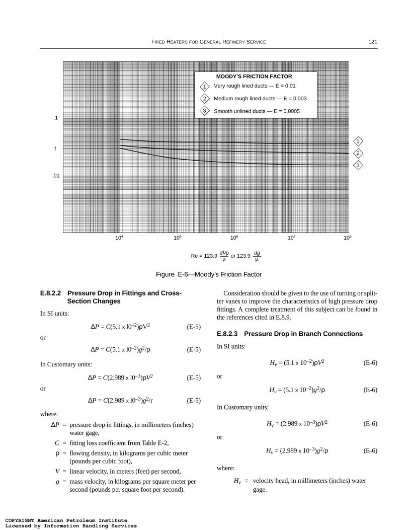
FIRED HEATERS FOR GENERAL REFINERY SERVICE 121
E.8.2.2 Pressure Drop in Fittings and Cross-Section Changes
In SI units:
∆P = C(5.1 x l0–2)ρV2 (E-5)
or
∆P = C(5.1 x l0–2)g2/ρ (E-5)
In Customary units:
∆P = C(2.989 x l0–3)ρV2 (E-5)
or
∆P = C(2.989 x l0–3)g2/r (E-5)
where:
∆P = pressure drop in fittings, in millimeters (inches) water gage,
C = fitting loss coefficient from Table E-2,
ρ = flowing density, in kilograms per cubic meter (pounds per cubic foot),
V = linear velocity, in meters (feet) per second,
g = mass velocity, in kilograms per square meter per second (pounds per square foot per second).
Consideration should be given to the use of turning or split-ter vanes to improve the characteristics of high pressure dropfittings. A complete treatment of this subject can be found inthe references cited in E.8.9.
E.8.2.3 Pressure Drop in Branch Connections
In SI units:
Hv = (5.1 x 10⁻²)ρV2 (E-6)
or
Hv = (5.1 x 10⁻²)g2/ρ (E-6)
In Customary units:
Hv = (2.989 x 10⁻³)ρV2 (E-6)
or
Hv = (2.989 x 10⁻³)g2/ρ (E-6)
where:
Hv = velocity head, in millimeters (inches) water gage.
Figure E-6—Moody’s Friction Factor
1
2
3
108107106105104
.1
f
.01
Re = 123.9 or 123.9dVρµ
dgµ
1
2
3
MOODY’S FRICTION FACTOR
Very rough lined ducts — E = 0.01
Medium rough lined ducts — E = 0.003
Smooth unlined ducts — E = 0.0005
COPYRIGHT American Petroleum InstituteLicensed by Information Handling ServicesCOPYRIGHT American Petroleum InstituteLicensed by Information Handling Services

122A
PI S
TA
ND
AR
D 560
500 80020090
FLUE GAS FLOW RATE, THOUSANDS OF POUNDS PER HOUR
PR
ES
SU
RE
DR
OP
—IN
CH
ES
OF
WA
TE
R P
ER
100
LIN
EA
L F
EE
T A
T D
UC
T, ∆
P1
108"
104"
100"
96"
92"
88"
84"
80"
76"
72"
68"
64"
60"
56"
52"
48"
44"
40"
36"
32"
28"
24"
20"
18"
16"
14" I
nsid
e di
amet
er (o
r de)
Velocity =50 feet persecond
50 150
10.0
8.0
6.0
4.0
2.0
1.0
0.6
0.8
0.1
0.2
0.4
Pressure drop for flue gases (MW = 28)at 14.5 pounds per square inch gage
(approximately 5.3 inches WC) in ducts
300 400 500 600 700
1.20
1.15
1.10
1.05
1.0
0.95
0.90
0.85
0.80
FLUE GAS TEMPERATURE, °F
C1
PR
ES
SU
RE
DR
OP
CO
RR
EC
TIO
N
Temperaturecorrectionfactor
Figure E-7—Pressure Drop for Flue Gases in Ducts
COPYRIGHT American Petroleum InstituteLicensed by Information Handling ServicesCOPYRIGHT American Petroleum InstituteLicensed by Information Handling Services

FIRED HEATERS FOR GENERAL REFINERY SERVICE 123
Table E-2—Fittings
Fitting Type Fitting IllustrationDimensional
ConditionLoss
Coefficient L/D or L/W
Elbow of “N” degree turn(rectangular or round)
No vanes N/90 times the value for a similar 90° elbow
90° round section elbow Miter (Note a)0.5 (R/D)
1.01.52.0
1.300.900.330.240.19
6545171210
90° rectangular section elbow
Miter 0.25 (H/W)0.5 (R/W)
1.01.5
Miter 0.5 (H/W)0.5 (R/W)
1.01.5
Miter 1.0 (H/W)0.5 (R/W)
1.01.5
Miter 4.0 (H/W)0.5 (R/W)
1.01.5
1.251.250.370.191.471.100.280.131.501.000.220.091.350.960.190.07
252574
494094
7550114.5
11085176
90° miter elbow with vanes C = 0.1 to 0.25
Mitered tee with vanes Equal to an equivalent elbow (90°)(base loss on the entering velocity)
Formed tee Equal to an equivalent elbow (90°)(base loss on the entering velocity)
Notes:aThis value is for a two-piece miter. For three-, four-, or five-piece miters, see Figure E-8.bFor permanent loss in venturis, use a loss coefficient of 0.05 based on throat area.
N
D
R
W
RH
COPYRIGHT American Petroleum InstituteLicensed by Information Handling ServicesCOPYRIGHT American Petroleum InstituteLicensed by Information Handling Services
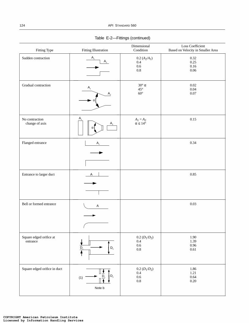
124 API STANDARD 560
Table E-2—Fittings (continued)
Fitting Type Fitting IllustrationDimensional
ConditionLoss Coefficient
Based on Velocity in Smaller Area
Sudden contraction 0.2 (A2/A1)0.40.60.8
0.320.250.160.06
Gradual contraction 30° α45°60°
0.020.040.07
No contractionchange of axis
A1 = A2α ≤ 14°
0.15
Flanged entrance 0.34
Entrance to larger duct 0.85
Bell or formed entrance 0.03
Square edged orifice at entrance
0.2 (D1/D2)0.40.60.8
1.901.390.960.61
Square edged orifice in duct 0.2 (D1/D2)0.40.60.8
1.861.210.640.20
A1
A1
A2
A1
A2
A2
A
A
D1
D1D2
D2
(1)
Note b
A1
α
α
COPYRIGHT American Petroleum InstituteLicensed by Information Handling ServicesCOPYRIGHT American Petroleum InstituteLicensed by Information Handling Services
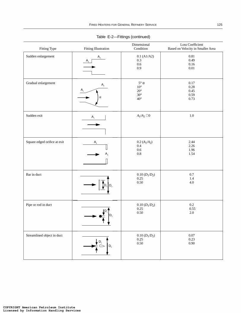
FIRED HEATERS FOR GENERAL REFINERY SERVICE 125
Sudden enlargement 0.1 (A1/A2)0.30.60.9
0.810.490.160.01
Gradual enlargement 5° α10°20°30°40°
0.170.280.450.590.73
Sudden exit A1/A2 ≅ 0 1.0
Square edged orifice at exit 0.2 (A1/A2)0.40.60.8
2.442.261.961.54
Bar in duct 0.10 (D1/D2)0.250.50
0.71.44.0
Pipe or rod in duct 0.10 (D1/D2)0.250.50
0.20.552.0
Streamlined object in duct 0.10 (D1/D2)0.250.50
0.070.230.90
Table E-2—Fittings (continued)
Fitting Type Fitting IllustrationDimensional
ConditionLoss Coefficient
Based on Velocity in Smaller Area
A1
A1
A2
A1
A2
A2
A1
D2D1
D1
D1
D2
D2
α
COPYRIGHT American Petroleum InstituteLicensed by Information Handling ServicesCOPYRIGHT American Petroleum InstituteLicensed by Information Handling Services
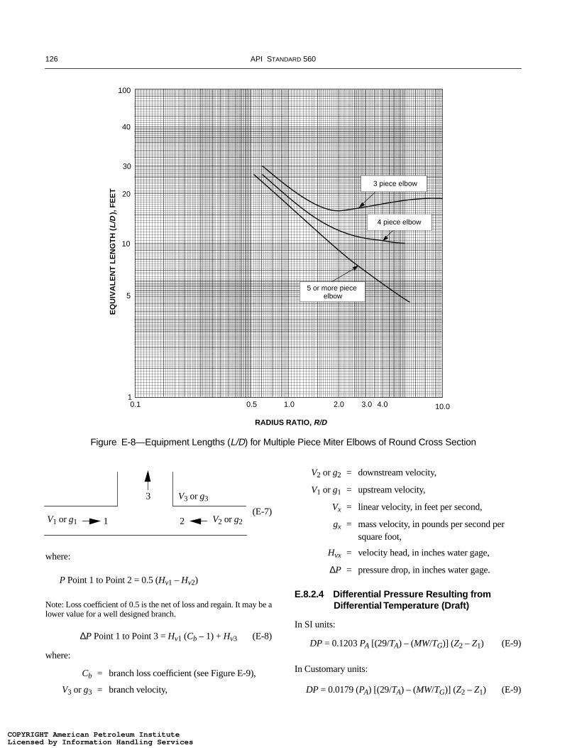
126 API STANDARD 560
(E-7)
where:
P Point 1 to Point 2 = 0.5 (Hv1 – Hv2)
Note: Loss coefficient of 0.5 is the net of loss and regain. It may be alower value for a well designed branch.
∆P Point 1 to Point 3 = Hv1 (Cb – 1) + Hv3 (E-8)
where:
Cb = branch loss coefficient (see Figure E-9),
V3 or g3 = branch velocity,
V2 or g2 = downstream velocity,
V1 or g1 = upstream velocity,
Vx = linear velocity, in feet per second,
gx = mass velocity, in pounds per second per square foot,
Hvx = velocity head, in inches water gage,
∆P = pressure drop, in inches water gage.
E.8.2.4 Differential Pressure Resulting from Differential Temperature (Draft)
In SI units:
DP = 0.1203 PA [(29/TA) – (MW/TG)] (Z2 – Z1) (E-9)
In Customary units:
DP = 0.0179 (PA) [(29/TA) – (MW/TG)] (Z2 – Z1) (E-9)
Figure E-8—Equipment Lengths (L/D) for Multiple Piece Miter Elbows of Round Cross Section
10.03.0
3 piece elbow
4.02.01.00.50.1
4 piece elbow
5 or more piece elbow
RADIUS RATIO, R/D
EQ
UIV
AL
EN
T L
EN
GT
H (
L/D
), F
EE
T
1
5
10
30
20
40
100
3
V1 or g1 1 2 V2 or g2
V3 or g3
COPYRIGHT American Petroleum InstituteLicensed by Information Handling ServicesCOPYRIGHT American Petroleum InstituteLicensed by Information Handling Services

FIRED HEATERS FOR GENERAL REFINERY SERVICE 127
where:
DP = draft, in millimeters (inches) water gage,
PA = atmospheric pressure at site grade, in kilopascals (pounds per square inch absolute),
TA = temperature of ambient air, in degrees Kelvin (Rankine),
TG = temperature of flue gas or air in duct, in degrees Kelvin (Rankine),
MW = molecular weight of flue gas,
Z1 = elevation of Point 1 above grade, in meters (feet),
Z2 = elevation of Point 2 above grade, in meters (feet).
E.8.3 ZONE CONCEPT
Regardless of which type of air preheat system is used,one or more of the duct zones shown in Figure E-10 willprobably be involved. The knowledge of the basic flows,temperatures. and pressure drops for equipment pointed outin F.8.1 as well as a knowledge of the basic spatial relation-ships of the components of the system are mandatory tobegin meaningful calculations.
E.8.3.1 Forced Air Zone
The basic elements in this zone will be the fired heaterburners and plenum or heater duct, the air preheater, theforced draft fan, and the inlet trunk or silencer. The nature ofthis zone makes it necessary that the calculations commenceat the downstream terminus or burner exit.
Figure E-9—Branch Loss Coefficients
BRANCH TO MAIN VELOCITY RATIO, V3 /V1
3.00.5 1.0 1.5 2.0 2.5
2.0
1.0
0
5.0
4.0
6.0
3.0
Cb B
RA
NC
H L
OS
S C
OE
FF
ICIE
NT
, BA
SE
D O
N U
PS
TR
EA
M M
AIN
VE
LO
CIT
Y
0
90° Take-Off
60° Take-Off
45° Take-Off
COPYRIGHT American Petroleum InstituteLicensed by Information Handling ServicesCOPYRIGHT American Petroleum InstituteLicensed by Information Handling Services

128 API STANDARD 560
The pressure at the burner location inside the fired heaterwill be the starting point. The pressure drop across the burnermust be added to this pressure (whether it be negative or pos-itive) to obtain the plenum or burner duct pressure. This maybe negative, positive, or zero, depending on the combinationof heater pressures and burner pressure drop.
At this point some form of branch connection or headerduct calculation may be necessary depending on the configu-ration of the burners and the ductwork. Some allowanceshould be made for any dampers or flow measurementdevices between the fired heater and the air preheater.
The air preheater air-side pressure drop should be knownfrom the performance data provided by the manufacturer.Any air leakage should also be known since this must beadded to the burner air flow to determine the flow ratebetween the air preheater and the forced draft fan.
Clearly, the sum of the heater plenum or header duct pres-sure, the duct pressure drop including dampers and flowdevices, and the preheater air-side pressure drop will deter-mine the forced draft fan discharge pressure. Equally clearis that the forced draft fan suction pressure will be atmo-spheric pressure less the inlet trunk or silencer pressure
drop. This pressure drop would normally be available fromthe manufacturer.
E.8.3.2 Induced Draft Zone (Furnace to Induced Draft Fan)
The elements in this zone normally consist of the firedheater convection section. the stack breeching and lowerstack section, the isolation damper, the air preheater. and theinduced draft fan. For the normal negative pressure heater set-ting, it is desirable to maintain the pressure immediatelybelow the convection section at some predetermined slightlynegative value. For this reason, the calculation for this zoneshould start at that point.
The pressure drop through the convection section shouldbe available from the heater manufacturer. The convectionsection pressure drop taken in the direction of flow is a nega-tive value and must be numerically added to the starting pres-sure. All pressures leading to the induced draft fan will beincreasingly negative. Having determined the pressure at theexit from the convection section, the pressure drops from thispoint on are for ducts (including lower stack section andbreeching) and the flue gas side of the preheater.
Figure E-10—Duct Zones
Air preheater Forced draft fanFurnace plenum
Air preheater Induced draft blower
Induced draft blower
From air preheater
Stack with damper
Stack with damper
Furnaceconvectionsection
TYPICAL FLUE GAS RETURN ZONEINDUCED DRAFT BLOWER TO TOP OF STACK
TYPICAL INDUCED DRAFT ZONEFURNACE TO INDUCED DRAFT BLOWER
TYPICAL FORCEDAIR ZONE
Inlet trunkor silencer
Fuel
To stack
COPYRIGHT American Petroleum InstituteLicensed by Information Handling ServicesCOPYRIGHT American Petroleum InstituteLicensed by Information Handling Services

FIRED HEATERS FOR GENERAL REFINERY SERVICE 129
One point must be considered in any system of this type.Some pressure differential will exist across the isolationdamper, and assuming that no bypassing will be permitted,some recycle leakage may occur. That is, some cooled fluegas in the stack above the isolation damper may leak throughand flow along with the hot flue gas to the air preheater andinduced draft fan and simply become recycle. Such recyclewill reduce the effectiveness of the air preheater, and if theamount is large, may overload the fan. Unless positive stepsare taken to avoid this, some allowance should be made in theflow rate and temperature of the flue gas going to the air pre-heater and the induced draft fan.
The pressure drop across the flue gas side of the air pre-heater should be known from the manufacturer. If there is anyair leakage across the air preheater, it must be added at thispoint to determine the flow rate to the induced draft fan.
In summary, the numerical sum of the pressure required atthe entry to the convection section; the convection sectionpressure drop; and the pressure drop in the breaching, lowerstack, ductwork, including any dampers, and the preheatergas side will be the negative suction pressure for the induceddraft fan.
Note: Pressure drops are sometimes referred to as draft losses.
E.8.3.3 Flue Gas Return Zone (Induced Draft Fan to Top of Stack)
The elements in this zone consist of the induced draft fan,the cold flue gas ductwork, and the top of the stack. It shouldbe noted that a separate stack could be utilized so that the fluegas is not returned to the original stack.
Zone calculation must commence from the downstreamexit or the atmosphere at the top of the stack. It is useful totreat the stack as simply an extension of the ductwork so thatthe calculation is reduced to a series of duct pressure drops.The sum of these pressure drops, when corrected for drafteffects, becomes the induced draft fan discharge pressure.Any comments made about leakages (see E.8.3.1) must beconsidered in this zone.
E.8.4 DRAFT EFFECTS
All duct calculations must account for differential pressureresulting from thermal differences, commonly known as thedraft effect. This effect can produce either positive or negativepressure depending on location and conditions. It must beaccounted for in determining net pressure losses or gains inany system. It is often only referred to for the calculationinvolving the stack, but draft effects are present for any situa-tion involving air or gas having a temperature different fromthe ambient temperature.
E.8.5 DUAL DRAFT SYSTEM
In those systems with burners intended to be operated onnatural draft as well as in the forced or induced draft mode, thesizing and arranging of ducts, plenums, and air door compo-nents must accommodate both types of operations. Theheater’s draft must be adequate to overcome the friction lossesof the system between the burner and the atmosphere. To facil-itate swift conversion to natural draft, it is common practice toprovide “natural draft air doors” on, or adjacent to, the burnerplenum. These doors will fail open as appropriate to provide alocal source of ambient combustion air for the heater.
E.8.6 VELOCITY GUIDELINES
In the absence of specific values, the designer may con-sider the following recommended duct velocities:
a. Straight ducts; Recommended velocity of 15.2 m/sec (50ft/sec).
b. Turns or tees; Recommended velocity of 15.2 m/sec (50 ft/sec). Note that a lower velocity may be economically justifiedby reduced hydraulic losses.
c. Burner air supply ducts; Recommended velocity, 7.6–10.7m/sec (25–35 ft/sec). An alternative design approach is to setthe velocity head in these ducts equal to 10% of the burnerdP.
E.8.7 DAMPER CONSIDERATIONS AND SELECTION
E.8.7.1 General
In any attempt at duct system design, consider the place-ment and selection of dampers for control and isolation ofvarious elements of the system. When selecting a damper,consider the operating differential pressure and the tempera-ture across it. Some situations will require a much sturdierdesign than others.
If balancing dampers are deemed necessary in the air sup-ply system, they should operate manually and should lockpositively in the chosen position. Consider what measure-ments will be made or criteria set for selecting the damperposition before judging that a damper is required.
Guillotine blinds or slide gates may be used to isolateequipment, either after a change to natural draft or when iso-lating one of several heaters served by a common preheat sys-tem. Consider exposure of personnel, the effects of leakageon heater operation, the tightness of damper shutoff, and thelocation of the damper (close to or remote from the affectedheater).
Multiple louver, opposed blade dampers are preferred forcontrol applications. They provide better control characteris-tics. Parallel blade or single blade dampers should not beapplied where the flow directing feature inherent in their
COPYRIGHT American Petroleum InstituteLicensed by Information Handling ServicesCOPYRIGHT American Petroleum InstituteLicensed by Information Handling Services
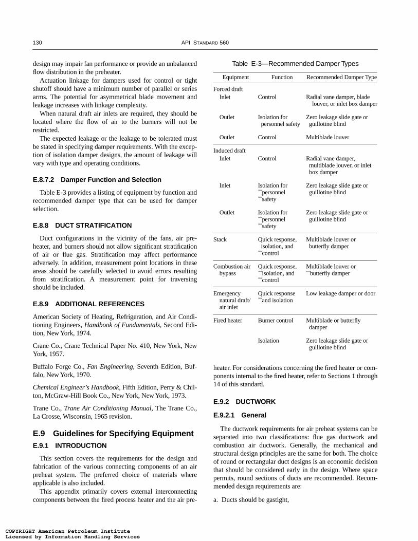
130 API STANDARD 560
design may impair fan performance or provide an unbalancedflow distribution in the preheater.
Actuation linkage for dampers used for control or tightshutoff should have a minimum number of parallel or seriesarms. The potential for asymmetrical blade movement andleakage increases with linkage complexity.
When natural draft air inlets are required, they should belocated where the flow of air to the burners will not berestricted.
The expected leakage or the leakage to be tolerated mustbe stated in specifying damper requirements. With the excep-tion of isolation damper designs, the amount of leakage willvary with type and operating conditions.
E.8.7.2 Damper Function and Selection
Table E-3 provides a listing of equipment by function andrecommended damper type that can be used for damperselection.
E.8.8 DUCT STRATIFICATION
Duct configurations in the vicinity of the fans, air pre-heater, and burners should not allow significant stratificationof air or flue gas. Stratification may affect performanceadversely. In addition, measurement point locations in theseareas should be carefully selected to avoid errors resultingfrom stratification. A measurement point for traversingshould be included.
E.8.9 ADDITIONAL REFERENCES
American Society of Heating, Refrigeration, and Air Condi-tioning Engineers, Handbook of Fundamentals, Second Edi-tion, New York, 1974.
Crane Co., Crane Technical Paper No. 410, New York, NewYork, 1957.
Buffalo Forge Co., Fan Engineering, Seventh Edition, Buf-falo, New York, 1970.
Chemical Engineer’s Handbook, Fifth Edition, Perry & Chil-ton, McGraw-Hill Book Co., New York, New York, 1973.
Trane Co., Trane Air Conditioning Manual, The Trane Co.,La Crosse, Wisconsin, 1965 revision.
E.9 Guidelines for Specifying EquipmentE.9.1 INTRODUCTION
This section covers the requirements for the design andfabrication of the various connecting components of an airpreheat system. The preferred choice of materials whereapplicable is also included.
This appendix primarily covers external interconnectingcomponents between the fired process heater and the air pre-
heater. For considerations concerning the fired heater or com-ponents internal to the fired heater, refer to Sections 1 through14 of this standard.
E.9.2 DUCTWORK
E.9.2.1 General
The ductwork requirements for air preheat systems can beseparated into two classifications: flue gas ductwork andcombustion air ductwork. Generally, the mechanical andstructural design principles are the same for both. The choiceof round or rectangular duct designs is an economic decisionthat should be considered early in the design. Where spacepermits, round sections of ducts are recommended. Recom-mended design requirements are:
a. Ducts should be gastight,
Table E-3—Recommended Damper Types
Equipment Function Recommended Damper Type
Forced draftInlet Control Radial vane damper, blade
louver, or inlet box damper
Outlet Isolation for personnel safety
Zero leakage slide gate or guillotine blind
Outlet Control Multiblade louver
Induced draftInlet Control Radial vane damper,
multiblade louver, or inlet box damper
Inlet Isolation for personnel safety
Zero leakage slide gate or guillotine blind
Outlet Isolation for personnel safety
Zero leakage slide gate or guillotine blind
Stack Quick response,isolation, and
control
Multiblade louver or butterfly damper
Combustion airbypass
Quick response, isolation, and control
Multiblade louver or butterfly damper
Emergencynatural draft/air inlet
Quick response and isolation
Low leakage damper or door
Fired heater Burner control Multiblade or butterfly damper
Isolation Zero leakage slide gate or guillotine blind
COPYRIGHT American Petroleum InstituteLicensed by Information Handling ServicesCOPYRIGHT American Petroleum InstituteLicensed by Information Handling Services

FIRED HEATERS FOR GENERAL REFINERY SERVICE 131
b. Field joints should be flange-and-gasket or seal-weldedconstruction,
c. Ductwork should permit replacement of components, suchas dampers, blowers, heat exchangers, and expansion joints,
d. Ductwork should provide uniform fluid flow distributioninto the air preheater exchanger.
Failure to achieve a uniform velocity distribution maycause a reduction in performance of the air heating device.Internal duct bracing, if used, should not be installed withinthree diameters of equipment since disruption or restriction ofthe flow may occur. Use of turning vanes or air straightenersshould be considered to ensure uniform distribution.
E.9.2.2 Cross Section
Round ductwork is structurally simpler than rectangularductwork and requires less material to contain the duct flowarea. It can be reinforced with simple stiffening rings andgenerally requires less material for structural support. Itcan be designed for maximum flow area per unit of ductweight.
Rectangular ducts need to be reinforced in a manner thatwill keep the deflections and stresses within acceptable limits.Also, the designer should avoid having the flat side of ductscoincidently resonant with blower or fan speeds. Designingfor possible buckling of flat walls may require additionalbracing for stiffness.
E.9.2.3 Plenums or Wind Box
The plenum design and layout shall be such that there is aclearance around and under the plenum to permit withdrawalof burner parts without dismantling the plenum. The plenumshall not enclose the structural supports of the fired processheater without providing for structural integrity. Plenumdesign should be such that the process heater floor structuredoes not fail in the event of a fire in the plenum.
In retrofit situations, the design of floor support beamsin the existing process heater shall be verified during thedesign for the effects of preheated air on structural integ-rity. Separate insulated plenum boxes may be required.The use of air spaces between main structural supports andpreheated air plenums should be considered during thedesign.
E.9.2.4 External or Internal Duct Linings
Internal insulation or refractory should be considered forflue gas ducts to reduce the metal temperature of the ductenvelope, thereby reducing the duct thermal expansion. In theevent of a fire in the duct system, refractory linings are desir-able. Refractory, however, can break loose from the duct walland result in clogged ductwork, plugged air preheaters, andpossible damage to fans. Loss of internal linings also will
expose ductwork to corrosive attack and temperatures higherthan design.
External insulation of ductwork may be desirable to main-tain metal temperature and to prevent dew point corrosion.The ductwork will develop greater thermal expansion how-ever, since the metal temperature is higher. External insula-tion can be applied after the ductwork has been set in place; itis not subject to shipping damage that may occur when insu-lation or refractory has been shop applied.
E.9.2.5 Design Considerations
E.9.2.5.1 Design Pressure
Ductwork should be structurally designed for the maxi-mum expected shut-in pressure of the blower or the differ-ential pressure [that is, the outside atmospheric pressureminus the internal maximum operating pressure in absoluteunits of not less than 3.4 kilopascals (0.5 pounds per squareinch {13.85 inches of water})] whichever is greater. If thedesign defaults to 3.4 kilopascals (0.5 pound per squareinch) minimum design differential pressure, it shall beassumed that the fluid pressure is positive within the duct.Flat surfaces on the rectangular ductwork, if operating atless than atmospheric pressure inside the duct, shall bedesigned for the expected vacuum. Additional reinforce-ment may be required for transient conditions or resonantfan conditions.
E.9.2.5.2 Design Loads
Duct and supports should be designed to accommodateall thermal and mechanical loads that may be imposed,including erection (including the weight of wet refractoryduring startup, operation, or shutdown of the system).Where duct sections may be removed for maintenanceactivities, the effect of existing loads and new forces resultsin changes of deflection or stress; the entire system designshall again be mechanically verified in accordance withcodes or procedures agreed to by the user and the vendor.The loads and thermal effects of cold weather design condi-tions (that is, snow and ice) during shutdowns should beconsidered in the analysis of ductwork.
E.9.2.5.3 Thermal Expansion
All ductwork subject to thermal expansion should be ana-lyzed for thermal stresses encountered at the design pressureand design metal temperature. All ductwork subject to ther-mal expansion shall have supports designed to freely accom-modate the expected movement resulting from thermaleffects or to accept the forces and stresses. The use of rollers,graphite slides, or polytetrafluoroethylene slide plates may berequired to prevent binding of support shoes.
COPYRIGHT American Petroleum InstituteLicensed by Information Handling ServicesCOPYRIGHT American Petroleum InstituteLicensed by Information Handling Services

132 API STANDARD 560
E.9.2.5.4 Layout and Routing Considerations
Following are recommended ductwork layout and routingguidelines:
a. All flue gas ducts that tie into a heater stack, should have astructural anchor (on the duct) close to the stack tie-in point.An expansion joint should be located between the fixed point(i.e., anchor) and the stack to minimize the duct thermalexpansion forces and the resultant significant bendingmoment.
b. A single stack is recommended for “common” APH sys-tems that service multiple heaters.
c. Manually adjustable and lockable biasing dampers shouldbe provided in all applications that have parallel air ducts con-nected to a common header. Each parallel air duct shouldhave its own biasing damper to provide a means for adjustingthe airflow in each duct.
d. All duct sections should be equipped with low point drainconnections. These connections should not be less than 11/2inch nominal pipe size.
e. Manways should be a minimum of 460 by 460 mm (18 byl8 inches) and so located in ductwork (if size permits) to pro-vide for internal access to the entire duct system.
f. Vertical, self-supporting cylindrical ducts should bedesigned as stacks. They should be designed to safely with-stand wind loads and wind-induced (vortex shedding)vibrations in accordance with Section 9.5 of this standard.
g. Structural force should not be imposed on expansionjoints.
h. Duct system expansion characteristics for lined ductsshould be based on a calculated shell temperature plus 55°C(100°F).
E.9.3 EXPANSION JOINTS
All ductwork subject to thermal expansion shall be fur-nished with metallic bellows or flexible fabric bellows expan-sion joints suitable for gas temperatures expected in theductwork and resistant to any corrosion products in the gasstream. Internal sleeve liners to protect the bellows of theexpansion joint should be considered. Stiffening rings may beinstalled on either end of expansion joints in the ductwork toprevent ovalling of the ductwork or other distortion of theductwork in the event of replacement of the expansion joint.
Flexible fabric joints of suitable materials for the tempera-ture of the flowing gas in the ductwork may be used to avoiddeforming and stressing of adjoining equipment. Theseexpansion joints are generally of layered insulated construc-tion and can be constructed to withstand the flowing gas tem-perature. When soft (fabric) expansion joints are usedadjacent to components requiring steam cleaning or water
washing, the use of internal sleeves is recommended to pre-vent water damage to the fabric joint.
All ducts having expansion joints at both ends shall be suit-ably anchored or restrained between the joints to ensureabsorption of ductwork thermal growth in the expansionjoints in the desired manner.
If duct thermal expansion is deliberately controlled tocause lateral deflection in the expansion joint, the expansionjoint shall be specified to absorb lateral deflection or angula-tion without overstressing the bellows material at design tem-perature. Expansion joints subject to lateral deflection onlyshall be provided with tie rods across the bellows. The tie-rodconnections to the duct work shall be gimbaled to allow lat-eral displacement in the expansion joint without bending orshearing the tie rods or tie rod connections.
Do not use a tied expansion joint to absorb both axial andlateral deflections. Only internal pressure thrusts are con-tained by tie rods.
Packed slip expansion joints may be considered for nega-tive pressure applications and shall be designed to providepositive retention of the packing to permit packing replace-ment from the outside while the duct is in service. Thesejoints should be between solid anchor points in hot ductwork.They are subject to binding because of dirt, paint, or corro-sion. Avoid using slip-type joints adjacent to blower/ fan inletor outlet flanges. Slide bars or guide pins shall be provided toprevent angulation or cocking in the gland if stress or frictionwithin the gland is not consistent around the circumference.Packed expansion joints can be designed to take horizontalmovements if used as two hinged joints.
E.9.4 DAMPERS
E.9.4.1 General
Dampers may be classified into four types based upon theamount of internal leakage across the closed damper at oper-ating pressures.
a. Tight shutoff—low leakage.
b. Isolation or guillotine (slide gate)—no leakage.
c. Flow control or distribution—medium to high leakage.
d. Natural draft air inlet doors—low leakage to full open.
Tight shutoff dampers may be of single blade or multibladeconstruction. Leakage rates of 0.5 percent or less of flow atoperating conditions are typical.
Isolation or guillotine (slide gate) dampers are designed tohave no internal leakage when closed and may include dou-ble-gate with air purge or double-block-and-bleed designsconsisting of one or more dampers in series with an air purgebetween. Internal leakage rates of 0 percent are expected withthis type of damper. Dampers may have insulated blades toallow personnel to safely enter ductwork (downstream of thedamper) during operation of connected equipment.
COPYRIGHT American Petroleum InstituteLicensed by Information Handling ServicesCOPYRIGHT American Petroleum InstituteLicensed by Information Handling Services

FIRED HEATERS FOR GENERAL REFINERY SERVICE 133
Natural draft air inlet doors shall be designed as fail-opendevices in the event of loss of mechanical draft furnished bycombustion air fan.
E.9.4.2 Design and Construction
Damper frames shall be channels using either rolled struc-tural steel or formed plate. Material and weight of the framesshall be determined on the basis of any combined stress orindividual stress, whichever is the maximum resulting fromthe following loads:
a. Seismic.
b. Wind.
c. Shipping or erection loads.
d. Actuator loading.
e. System failure or thermal or dead weight load.
f. Corroded condition load.
Dampers should be considered structural members and assuch should meet all structural design criteria of fired heaterstructural members outlined in Section 8. Damper bladedeflections should be less than 1/360 of the blade span. Stressof each blade assembly component, based on maximum sys-tem static pressure, temperature, and seismic loading and themoment of inertia through the cross section of the bladeassembly, should not exceed those levels specified in AISCSpecification for Design, Fabrication, and Erection of Struc-tural Steel for Buildings. The torsional and bending stressshall be considered if the gas stream temperature is equal toor greater than 400°C (750°F). Allowable bending stressshould be limited to 60 percent of the yield stress at the speci-fied operating temperature. If the metal temperature is in thecreep range, the allowable stress will be based upon 1 percentof the rupture stress at the 100,000 hour life span.
Each damper shall be equipped with an actuator mountedand linked by the damper manufacturer and tested in his shopbefore shipment. The actuator and linkage shall be installedoutside of the flowing gas stream. The strength of the actuatormount on the damper frame shall be based on seismic loadingand required actuator torque. Its strength shall not exceed 10percent of the yield strength of the damper in any mode ofstress. Actuators and all drive system components shall besized with a 3.0 safety factor.
E.9.4.3 Isolation/Guillotine Damper
The slide gate damper shall be a complete, self-sufficientstructure not requiring additional integral support or bracing.The actuator for slide gate dampers shall be electric, manual,pneumatic, or hydraulic and shall be operated by sprockets,chains, jack screws, or a direct drive piston. If chains areused, a minimum of two chains should be used and arrangedto drive evenly on each side of the blade to prevent binding.
In the event of chain failure, the remaining chain or chainsmust support the entire blade load.
The time consumed in complete operation of the slide gatedamper from full open to full closed must be specified by theuser.
Operator and drive system sizing shall incorporate a 300percent dead load plus a 200 percent live load (push-pullopen/close) safety factor as a minimum. For installations thatare safe for personnel to enter, incorporate double block-and-bleed or double block-and-purge designs. The space betweendual closed damper blades or the space between two rows ofedge seals is normally purged with clean air of sufficientlygreater pressure than duct stream or outside air pressure toensure a clean air barrier to gas leaks into the duct system pastthe guillotine damper.
E.9.4.4 Louver Dampers
Louver dampers consist of a series of parallel damperblades. The blade construction may be a solid blade with acentral axial round shaft. If the blade of the damper is of air-foil composite design, the central shaft may consist of a struc-tural member as a central axial support of the airfoil blade. Ateach end, round stub shafts are splined into the axial struc-tural member with suitable clearances to prevent buckling ofthe shaft as it thermally expands as a result of heat. The stubshafts pass through the bearings mounted on the damperframe. The edges of the blades are fitted with metal seals tominimize leakage past the damper edges when the damperblade is closed. These seals are often of proprietary design.
Air foil blade designs shall have blade skins provided withelongated bolt holes to compensate for thermal growth of theshaft and blade skin. Consider the use of heating holes in oneside of sandwich (air foil) blade designs when excessive tem-peratures are encountered across closed dampers. This willreduce thermal stresses and warping of the blades. Blades andshafts shall be of thermally compatible material of similarthermal growth rates. If possible, provide for thermal growthof the damper blade away from the actuator or drive side ofthe damper.
Louver-style multiple damper blades shall be linkedtogether exterior to the damper frame. Linkage shall consistof structural bar hinged with shoulder bolts, complete withlock nuts set in self-lubricating bearings of a type specified bythe user. Other designs consisting of adjustable linkage tocompensate for the differential expansion between thedamper frame and the linkage to ensure tight shutoff at theoperating temperature should be considered. Completed link-ages shall be tested and fixed in position at the damper manu-facturer’s facility.
The link bars of each individual blade shall be welded toset collars fastened to the damper shaft with shear pins. Link-age shall be tight and vibration free and shall prevent inde-pendent action of the blade. The position of the damper on its
COPYRIGHT American Petroleum InstituteLicensed by Information Handling ServicesCOPYRIGHT American Petroleum InstituteLicensed by Information Handling Services

shaft shall be scribed on the end of the shaft visible from out-side the duct.
Other designs incorporating stainless steel stub shafts andlinkage pins and hardware consisting of cast steel clevis armsattached to stub shaft may eliminate corrosion and may facili-tate rapid removal. These designs should also be consideredin situations where dampers may not be used open and tend tofreeze.
Bearings shall be mounted in pillow block assemblies fur-nished by the bearing manufacturer and shall be bolted tobearing mounts welded to the damper frame. Each bearingand bearing mount, including welds holding the mount, shallhave a duty factor capable of withstanding 200 percent of thestress transmitted as a result of the system load acting on theblade plus the operator output torque. If removable bearingsare specified, linkage cranks shall be removable also. Do notweld linkage cranks to shafts.
A packing gland, if specified, shall be welded to thedamper frame at each shaft clearance hole and shall be filledwith packing adequate for the service. Design of the packinggland shall allow removal and replacement without removalof bearings or linkage. Packing glands are recommended innegative pressure flue gas service when sulfur bearing fuelsare used.
E.9.4.5 Miscellaneous Construction Details
The following miscellaneous features are recommended:
a. Dampers constructed integral to ducts should be of abolted design to allow replacement of parts.
b. Damper bearings shall not be covered by insulation.
c. Damper shafts shall be of Type 304 stainless steel as aminimum.
d. Bearing friction loads used for actuator design should berepresentative of a weathered, in service condition (not as-new shop values).
E.9.5 DUCTWORK INSULATION AND REFRACTORY
E.9.5.1 General
All insulation except castable (internal or external) shouldbe covered for weather protection during erection. Internalexposed insulation should be treated for stability or rigidity.
Externally insulated air and flue gas duct sections shouldbe covered with weatherproofing and/or metal covers. Theinsulating material or any layer shall be suitable for a servicetemperature of at least 170°C (300°F) above its calculatedhotface interface temperature.
Duct internal casing surfaces covered by a blanket or blockinsulation shall have either a protective coating applied priorto application of insulating material or a vapor barrier if the
flue gas contains products of combustion from fuels contain-ing more than 1 percent by weight of sulfur in fuel oil or 1.5percent by volume hydrogen sulfide in the fuel gas.
E.9.5.2 Castable Refractory
The minimum castable refractory thickness should be 2 in.(50 mm). The service temperature of the castable refractoryshould be least 300°F (170°C) above the maximum calcu-lated temperature of the material. In fuel oil fired applica-tions, the burner plenum should minimize the absorption ofoil into the refractory. High density and/or oil resistant refrac-tory should be considered. Provide refractory on the floor ofthe plenum and for at least 4 in. (100 mm) up the side walls.
E.9.5.3 Ceramic Fiber Blanket Refractory
The application of unlined ceramic fiber blanket refractoryfor hot flue gas or combustion air ducts should be in accor-dance with Section 7 of this standard. Ceramic fiber blanketrefractory systems with protective metal liners should be inaccordance with API Recommended Practice 534. Whenceramic fiber construction is used, the casing shall have aninternal protective coating to prevent corrosion of metal duct-work. Do not use unlined ceramic fiber refractory in erosiveareas, such as duct bends, baffles, changes of axis, and/orchanges in flow areas.
E.9.5.4 Block and Board Refractory
Block insulation is defined as rigid, and board insulation assemi-rigid. Insulation should be specified as Class 3, ASTMC 612. If such insulation is not to be shielded by other materi-als, single layers may be used below 280°C (500°F) hot face.It may be used as a backup layer with other insulations when-ever the sulfur content does not exceed 1 percent by weight inliquid fuel or 100 parts per million of hydrogen sulfide in gasfuel.
The velocity of the flowing gas stream must not exceed 6m/s (20 ft/s) unless the surface is protected with wire mesh,expanded metal, or solid metal. Two layers of insulation arepreferred.
E.9.5.5 Mineral Wool Blanket Insulation
Blanket insulation is a flexible material specified perASTM C 553. Do not use unprotected insulation adjacent towater or steam cleaning devices. Surface protection consist-ing of wire mesh, expanded metal mesh, or chemical rigidiz-ers shall be provided for areas where flue gas or air velocitiesexceed 12 meters per second (40 feet per second). Two layersare preferred. Materials shall be overlapped in the hot face onthe first layer to ensure that no exposure of casing or ductenvelope to lower temperature insulating materials occurs.
COPYRIGHT American Petroleum InstituteLicensed by Information Handling ServicesCOPYRIGHT American Petroleum InstituteLicensed by Information Handling Services

135
E.9.6 FANS AND DRIVERS
E.9.6.1 General
All fan and driver design details should be in accordancewith Section 11 of this standard.
E.9.6.2 Wheel Types
Maximum aerodynamic efficiency for fans can be achievedwith backward inclined (nonoverloading) blades. The bladeconstruction may be of single thickness or air foil design. Onapplications where the fan provides induced draft service,avoid air foil designs that have hollow cross-section bladesconsisting of metal skin on ribs if they are not furnished withwheel cleaning facilities. Induced draft fans handling elevatedtemperature flue gas containing significant particulatesshould be considered and specified as radial or modifiedradial blades on the fan wheel.
E.9.6.3 Construction
Fans in combustion gas service should have continuouslywelded seams.
E.9.6.4 Shafts
Fan wheel shafts should be capable of handling 110 per-cent of rated driver torque from rest to design speed.
E.9.6.5 Elimination of Induced Draft Fan
A stack of greater height than normally required mightreplace an induced draft fan on some systems, therebyimproving the mechanical reliability of a system.
E.9.7 AIR PREHEAT EXCHANGERS
E.9.7.1 Design Considerations for Direct Preheaters
In a fixed bundle air preheater, consider making the bundleremovable if it will be subject to corrosion. Pressure parts ofcoils or tube bundles handling a combustible fluid should beof all welded construction. Do not permit circumferentialwelds to be located in the air stream.
In rotating exchangers with metallic elements, the heatingsurface should be provided in two or more layers. The cold-end layer of elements shall be in baskets for radial removalthrough a housing. Other layers may be in baskets forremoval through hot-end ductwork. Regenerative systemsusing revolving elements may be mechanically damaged ifrotation stops while flue gas and air flow continue. An auxil-iary drive on the preheater is recommended to protect againstloss of rotation resulting from a power failure or other cause.An alternative action is to revert to natural draft, bypassingthe preheater, until rotation can be reestablished.
E.9.7.2 Design Considerations for Indirect Heaters
Fluid pressure-retaining circumferential field welds on theair heating element of systems employing a pumped, circulat-ing, combustible heat medium shall be external to the airduct. Electric resistance welded tubing however is permittedfor coil designs where the coil is internal to duct.
Tubular coils shall meet the requirements of Section 3,except for the extended surface in the air duct, which shall beas required by the application.
Tube wall thickness shall be in accordance with APIStandard 530, assuming a design life of 100,000 hours and aminimum corrosion allowance of 1.59 mm (1/16 inch).
The extended surface shall not be included in designsintended for heavy oil fuel firing unless cleaning facilities arealso included in the system.
Each pass of multiple pass coils shall be symmetrical andequal in length to all other passes. The design pressure of thecoils in heated liquid service shall be based upon a pressuregreater than the vapor pressure of the heating fluid at theoperating temperature. This will ensure that the coil designpressure will be great enough to allow selection of pumpingpressures sufficient to prevent possible two-phase (liquid/vapor) flowing regimes in the coils and to contain and holdthe fluid should the blower fail with no reduction in heatinput.
Recirculating reheat coils shall not be oriented to viewdirect radiation from the firebox or from high temperaturerefractory surfaces.
The performance of recirculating reheat coils is directlyrelated to and dependent on the characteristics of the recircu-lating heat transfer medium in the coil. Some characteristicsof the medium deteriorate with extreme service conditions.Systems with pumped closed circulating heat medium loopsshould incorporate provisions to drain the heat medium fluidfrom the heating coil in the event of low fluid flow or highflue gas temperature. Drainage should be manually or auto-matically actuated. Failure to drain the heating coil underthese conditions may lead to thermal degradation or coking ofthe fluid in the coil.
All heating coils shall be drainable and shall include a highpoint vent and a low point drain unless specifically deleted bythe user because of more appropriate locations in adjacentpiping. All connection flanges should be located outside theduct periphery.
E.9.7.3 Two-Phase Operation
To ensure against “vapor lock” of the heat transfer fluid inthe coils, elevate the system pressure to a level above thevapor pressure of the liquid, which ensures that the coil con-tains all liquid, and then reduce the pressure directly in avapor “flash” drum downstream of the coil.
COPYRIGHT American Petroleum InstituteLicensed by Information Handling ServicesCOPYRIGHT American Petroleum InstituteLicensed by Information Handling Services

136 API STANDARD 560
E.9.7.4 Pump Design for Circulating Systems
Pumps should be designed in accordance with API Stan-dard 610. Head capacity curves shall rise continuously to shutoff. Rated pump capacity shall fall to the left or on the peakefficiency line. Pumps handling flammable or toxic liquidsshall have flanged suction and discharge nozzles. Sparepumps should be provided unless used in a system that can becompletely bypassed without detriment to the normal heaterservice.
E.9.7.5 Interconnecting Piping
Piping used to interconnect various components in an airpreheat system should be designed and fabricated in accor-dance with ASME B31.3.
E.10 Environmental ImpactThere are five basic ways the that use of an air preheat sys-
tem can have an environmental impact (see E.10.1 throughE.10.5). In general, the environmental impact of a properlydesigned air preheat system is positive.
E.10.1 ENERGY CONSERVATION
Air preheat systems are one of the best available technol-ogies for conserving fuel. An air preheat system frequentlyprovides adequate savings through reduced fuel cost toallow other pollution control systems to become economi-cally feasible.
E.10.2 STACK EMISSIONS
The use of an APH system will result in a lower flue gasexit temperature, which will increase the possibility of anexhaust stack plume and/or “acid rain”. The normal way toeliminate any adverse effect is to increase the stack exitheight above grade, and/or increase the effluent velocity sothat natural diffusion and wind currents will minimize acidfallout.
Both Balanced Draft and Induced Draft systems incorpo-rate an ID Fan, which could be sized to provide the flowenergy to achieve high stack effluent velocities. Alternatively,a longer stack would provide additional draft and stack veloc-ity while simultaneously providing a higher emissions point.
The four primary flue gas pollutants of interest are the fol-lowing.
E.10.2.1 Sulfur Oxides
The sulfur oxide fraction of the flue gas is dependent solelyon the composition of the gas or oil burned and is not affectedto any extent by the air preheat system. However, since fuelconsumption is reduced when an air preheat system is used,the pounds of sulfur dioxide (SO2) emitted are reduced for
the same process duty. This results in a net reduction in SOxpollution (which is an environmental benefit).
E.10.2.2 Nitrogen Oxides
The oxides of nitrogen produced depend on the time, tem-perature, and the oxygen concentration of any specific fuel’scombustion process. The reactions involved are many andcomplex. The following can be stated in general:
a. NOx produced increases with increases in firebox or com-bustion temperature.
b. NOx produced decreases with decreases in excess air.
The above indicates that preheating combustion airincreases NOx production. This has been shown to be truewhen expressed as concentration in the flue gas. However, asin the case of the sulfur oxides, the weight of nitrogen oxidesexpressed as nitrogen dioxide emitted is reduced as efficiencyis increased. This tends to diminish the adverse effect of airpreheat and can, in those cases where efficiencies are substan-tially improved, actually reduce the quantity of NOx emitted.
Excess air appears to be the most significant factor in thecontrol of NOx formation. Since air preheat systems mostoften utilize forced draft burners, it is not only possible tooperate at extremely low excess air levels, but also to moreaccurately control the fuel/air ratio. On natural draft burners,the minimum excess air levels previously considered neces-sary to provide for operational variations have been 20 per-cent on gas fuels and 25 percent on oil fuels. Most burnermanufacturers represent that using their forced draft designsand preheated air requires minimum excess air levels of only5 percent on gas and 10 percent on oil fuels, and controls canbe furnished to ensure that these levels are maintained. Thislow excess air operation will reduce the NOx level.
E.10.2.3 Particulates
The formation of particulates during combustion is nor-mally a function of burner application and the specific fuelburned. The use of air preheat and the forced draft systemsinvolved have allowed burner manufacturers to reduce theformation of carbon when burning normal fuels. This canreduce the particulates formed as essentially the ash contentof the fuel. Therefore, the use of an air preheat systemreduces the total solids emission from many heater applica-tions since the amount of fuel burned, and hence of ash emit-ted, is reduced.
E.10.2.4 Combustibles
The presence of combustibles, such as unburned hydrocar-bons and carbon monoxide, in the flue gases from fired heat-ers is related to the incomplete combustion of the fuel. This inturn may result from insufficient excess air. The applicationof an air preheat system enhances the ability to burn fuels
COPYRIGHT American Petroleum InstituteLicensed by Information Handling ServicesCOPYRIGHT American Petroleum InstituteLicensed by Information Handling Services
FIRED HEATERS FOR GENERAL REFINERY SERVICE 137
completely at the lowest possible excess air level. As a result,unburned hydrocarbons and carbon monoxide pollutionshould be minimized with the application of an APH system.
E.10.3 NOISE
The main sources of noise from a fired heater are the burn-ers and fan(s). The application of an air preheat systemrequires that the burners be housed in an insulated enclosure.In addition, high efficiency heater systems employ thermallymore effective insulation and linings. Both of these measuresreduce the noise emitted from the burners. Consequently, anair preheat system normally attenuates the noise from theburners below the statutory level.
However, the use of fans associated with an air preheat sys-tem introduces a new noise source, which must be consideredin the initial design. Since adequate silencing techniques arecommercially available, it is only necessary for the designerto establish the noise level limit required so that the fan man-ufacturer can offer the appropriate selection.
In summary, although noise must be considered in thedesign of an air preheat system, it should not have anadverse impact on the overall environment of a typicalheater installation.
E.10.4 HEAT
The installation of an air preheat system results in a lowerflue gas exit temperature thereby reducing thermal pollution.
E.10.5 EFFLUENT
The air preheater can collect small quantities of solidscombined with sulfur. During washdown cycles, if required,the liquid effluent can contain particulates with a weak acidthat should be handled in an appropriate disposal system.Normally, the additional quantities produced as a conse-quence of the air preheat system are negligible.
E.11 Preparing an InquiryE.11.1 INTRODUCTION
The purpose of this section is to provide guidance and achecklist for obtaining sufficient information and data for
selecting the most economical air preheat system and for pre-paring the required inquiry. Prior to preparing an inquiry, it isrecommended that an economic study be conducted to justifythe installation of an air preheat system.
E.11.2 INQUIRY
Final selection of the air preheat system often requires costand technical information on more than one system. Thisinformation is usually obtained from suppliers responding tothe bid inquiry. An inquiry for an air preheat system shouldinclude:
a. Data sheets for the fired heater(s), existing or proposed.
b. Air preheater data sheets.
c. Air preheat system specifications and P&ID.
d. Plot plan, plot area, or definition of the APH system plotarea restrictions.
The data for item “a” above is often available from theOEM’s data book. The fired heater operating data must repre-sent the intended heater operation, which in the case of retro-fit may vary from the original design data. If so, both theoriginal and the intended operating data must be supplied.
E.11.3 AIR PREHEAT SYSTEM CHECKLIST
The following is a checklist of information and data to beincluded in the APH system inquiry.
a. Complete fired heater data sheets.
b. Environmental restrictions; NOx, SOx, UHC, CO, andnoise.
c. Space limitations.
d. Number of fired heaters to be served by the proposed airpreheat system.
e. Required reliability and service factor of the fired heater(s)in APH operation
f. Required heater performance in the event of APH equip-ment failure.
g. Applicable local building rules and regulations.
COPYRIGHT American Petroleum InstituteLicensed by Information Handling ServicesCOPYRIGHT American Petroleum InstituteLicensed by Information Handling Services

COPYRIGHT American Petroleum InstituteLicensed by Information Handling ServicesCOPYRIGHT American Petroleum InstituteLicensed by Information Handling Services

139
APPENDIX E.A—FLUE GAS DEW POINT DISCUSSION AND BIBLIOGRAPHY
E.A.1 Introduction
The furnace designer must be aware of the various designand operational factors that affect flue gas dew point and cor-rosion rates even though the designer only has control over afew of these variables. This summary of some of the moresignificant published test work describing the potentialimpact of these factors is intended to:
a. Broaden the designer’s understanding of this complexphenomenon.
b. Serve as a starting point for further individual study.
Wherever possible, results from commercial-size equip-ment are reported. The results from laboratory-size equip-ment may not be directly applicable to commercialequipment design.
Flue gas dew point and corrosion are primarily related tothe amount of sulfur trioxide present, not to the predominantamount of sulfur, which is present as sulfur dioxide. Thefactors that encourage or inhibit the oxidation of sulfurdioxide to sulfur trioxide are the significant factors. Many ofthese factors will be recognized as similar to the significantfactors in the production of oxides of nitrogen. The signifi-cant factors are:
a. Fuel sulfur content.
b. Fuel and flue gas additives.
c. Flue gas oxygen content.
d. Flue gas moisture content.
e. Combustion temperature (firing rate).
f. Furnace cleanliness.
g. Burner design.
E.A.2 Fuel Sulfur Content
Various investigators have differed on the impact of sul-fur content of the fuel on the flue gas dew point. Corbett [1]in his tests of a commercial-size oil-fired boiler with fuelsulfur content varying from 0.75 to 3.5 weight percentfound no direct relationship between flue gas dew point andthe sulfur content of the fuel. Corbett’s test results alongwith those of other investigators are plotted in Figures F.A-1through F.A-3. Corbett’s test results, along with those ofother investigators, using commercial-size boilers are tabu-lated in Table F.A-l.
In tests with laboratory-size combustors and fuel sulfurcontents in the range of 1 to 5 weight percents Rendle andWilson [2] report an increase of the flue gas dew point of
approximately 4°C (7.2°F) for each I percent increase in fuelsulfur. Taylor and Lewis [3] report an increase of the flue gasdew point of approximately 9°C (16.2°F) for each 1 percentincrease in fuel sulfur.
E.A.3 Fuel and Flue Gas Additives
In their laboratory-size combustor, Rendle and Wilson [2]reported that by injecting ammonia vapor into the partiallycooled flue gas at a rate of 0.06 pounds of ammonia perpound of fuel containing 3.2 weight percent sulfur, they wereable to reduce the dew point 89°C (160°F) to very close to thewater dew point.
In tests of commercial-size boilers, Clark and Childs [4]report a 14°C (25°F) drop in dew point with magnesiumhydroxide fuel additives.
E.A.4 Flue Gas Oxygen Content
If the flue gas oxygen content can be controlled to less than0.5 percent, the flue gas dew point can be dramatically low-ered. In tests of two operating industrial boilers, Bunz,Niepenberg, and Rendle [5] demonstrated reductions in dewpoint of 149°C (300°F) in one boiler and 38°C (100°F) inanother boiler as the flue gas oxygen was reduced from 1.4percent to 0.2 percent oxygen.
By reducing the excess air from 15 percent (approximately3 percent oxygen) to 5 percent (approximately 1 percent oxy-gen), Clark and Childs [4] report a dew point reduction of17°C (30°F) in a commercial boiler. With flue gas oxygencontent reductions from 8 percent to 3 percent at constantboiler load, Corbett’s data [3] indicates little change in dewpoint.
E.A.5 Flue Gas Moisture Content
Flue gas moisture is produced by the fuel hydrogen con-tent, ambient humidity, and atomizing steam. Martin 16] inanalytical laboratory tests reports an increase in dew point ofup to 8°C (15°F) as the flue gas moisture content increasedfrom 10 percent (typical fuel oil) to 18 percent (typical fuelgas).
E.A.6 Combustion Temperature (Firing Rate)
The commercial boiler data of Draaijer and Pel [7] indi-cates a 11°C (20°F) increase in flue gas dew point with a 50percent increase in firing rate and the boiler data of Bunz.Niepenberg, and Rendle 15] indicates a 25°C (45°F) increasein dew point with a 100 percent increase in firing rate.
COPYRIGHT American Petroleum InstituteLicensed by Information Handling ServicesCOPYRIGHT American Petroleum InstituteLicensed by Information Handling Services

140 API STANDARD 560
Figure E.A-1—Dew Point of Flue Gas Versus Sulfur in Fuel Oil (Test Data from Industrial Boilers)
Figure E.A-2—Dew Point of Flue Gas Versus Sulfur in Fuel Oil(Test Data from Industrial Boilers and Data of Attig and Sedor)
350D
EW
PO
INT
, °F
300
1.0 2.0 3.0 4.0 5.0 6.0150
200
250
WEIGHT PERCENT SULFUR IN FUEL OIL
Recommended minimum metal temperaturefor convection coils, fans, and duct steelexposed to flue gas
Draaijer and Pel (1961)Bunz, Niepenburg and Rendle (1967)Corbett (1953)Clark and Childs (1964)Martin (Oil) Martin (Gas)
AVG. MAX.LEGEND
350
DE
W P
OIN
T,
°F
300
1.0150
200
250
Attig and Sedor7 to 9 mils/yr corrosion rate10% excess air
1.0 2.0 3.0 4.0 5.0 6.0
WEIGHT PERCENT SULFUR IN FUEL OIL
Recommended minimum metal temperaturefor convection coils, fans, and duct steelexposed to flue gas
Draaijer and Pel (1961)Bunz, Niepenburg and Rendle (1967)Corbett (1953)Clark and Childs (1964)Martin (Oil) Martin (Gas)
AVG. MAX.
LEGEND
COPYRIGHT American Petroleum InstituteLicensed by Information Handling ServicesCOPYRIGHT American Petroleum InstituteLicensed by Information Handling Services

FIRED HEATERS FOR GENERAL REFINERY SERVICE 141
Figure E.A-3—Dew Point of Flue Gas Versus Sulfur in Fuel Oil(Test Data from Industrial Boilers and Data of Energy Technology, Inc.)
Table E.A-1—Flue Gas Dew Point Data from Oil-Fired Industrial Boilers
Investigator Boiler No.Fuel Sulfur
weight percent
AverageDew Point
°F
MinimumDew Point
°F
MaximumDew Point
°FTest
PointsSteam Load
1000 kg/hour
PercentExcess
O2
Draaijer & Pell 1 3.55 317 315 318 4 40 —(1961) 2 3.55 287 273 300 15 9–14 —
Bunz, Neipenberg, & 3 1.78 270 250 297 8 24 & 32 0.1–0.5Rendle (1967) 3 1.90 264 244 280 6 24 & 32 0.1–1.5
4 2.10 240 165 297 10 24 & 32 0.1–1.5 4 2.18 261 187 289 10 24 & 32 0.1–1.5 4 1.90 226 167 275 8 24 & 32 0.1–1.4 4 3.61 260 158 306 16 16, 24, & 32 0.1–1.4
Corbett 5 2.60 266 245 280 49 9–23 3.4–13.2(1953) 5 2.00 260 245 270 25 9–23 4.3–9.8
5 2.10 271 243 300 27 9–22 3.1–10.6 5 3.55 274 257 292 39 9–22 2.7–6.3 5 0.75 267 250 285 22 13–18 3.6–8.2
Clark & Childs 6 3.97 257 — — — — —(1964) 7 1.70 258 — — — — —
8 1.82 258 — — — — — 9 2.94 245 — — — — —10 3.29 274 — — — — —
R. Martin 11 (oil) 0.4 240a 287a 248a 8 100 2.7–3.6(1971) 11 (gas) 0.6 260a 252a 268a 15 100 2.5–3.3
aIndirect measurements from S03 concentration. Electrical conductivity probe method would probably give lower values.
350
300
150
200
250
Energy Technology, Inc. standards 0.7 to 3.5 percent S
DE
W P
OIN
T,
°F
1.0 2.0 3.0 4.0 5.0 6.0
WEIGHT PERCENT SULFUR IN FUEL OIL
Draaijer and Pel (1961)Bunz, Niepenburg and Rendle (1967)Corbett (1953)Clark and Childs (1964)Martin (Oil) Martin (Gas)
AVG. MAX.
Recommended minimum metal temperaturefor convection coils, fans, and duct steelexposed to flue gas
LEGEND
COPYRIGHT American Petroleum InstituteLicensed by Information Handling ServicesCOPYRIGHT American Petroleum InstituteLicensed by Information Handling Services

142 API STANDARD 560
E.A.7 Furnace CleanlinessIn a commercial-size boiler fired with heavy fuel oil, Clark
and Childs [4] report that the flue gas dew point is reduced17°C (30°F) after each annual furnace cleaning.
E.A.8 Burner DesignIn a laboratory combustor, Attig and Sedor [8] demon-
strated that recirculation of 25 percent of the flue gases to theburners reduced flue gas sulfur trioxide concentration by onehalf (equivalent to a dew point reduction of at least 6°C[10°F]) and reduced corrosion rates by more than one third.The very low excess air operations reported by Bunz, Niepen-berg, and Rendle [5] were achieved with a special low excessair design burner.
E.A.9 References1. Corbett, P. F., and Fereday, F., “The SO3 Content of theCombustion Gases from an Oil-fired Water-tube Boiler,”Journal of the Institute of Fuel, Vol. 26, No. 151, p. 92–106,1953.
2. Rendle, L. K. and Wilson, R. D., “The Prevention of AcidCondensation in Oil-fired Boilers,” Journal of the Institute ofFuel, Vol. 29, p. 372, 1956.
3. Taylor, R. P., and Lewis, A. “SO3 Formation in Oil Fir-ing,” paper presented at the Congress International du Chauf-fage Industrial, Gr. I l-Sect. 24 No. 154. Paris 1952.
4. Clark, N. D. and Childs, G. D., “Boiler Flue Gas Mea-surements Using A Dewpoint Meter,” Transactions of theASME, Journal on Engineering and Power, Vol. 87. Series A.No. 1, p. 8–12 January 1965.
5. Bunz, P., Niepenberg, H. P., and Rendle, L. K. “Influencesof Fuel Oil Characteristics and Combustion Conditions onFlue Gas Properties in Water-tube Boilers,” Journal of theInstitute of Fuel, Vol. 40, No. 320, p. 406–416, September1967.
6. Martin. R. R., “Effect of Water Vapor on the Production ofSulfur Trioxide in Combustion Processes,” doctoral disserta-tion 1971, University of Tulsa.
7. Draaijer, H., and Pel, R.J., “The Influence of Dolomite onthe Acid Dew Point and on the Low Temperature Corrosionin Oil-fired Boilers,” Brennet-Warne-Kraft 13. No. 6, p. 266–269, 1961.
8. Attig, R. C., and Sedor, P., “A Pilot-Plant Investigation ofFactors Affecting Low-Temperature Corrosion in Oil-FiredBoilers,” Proceedings of the American Power Conference,Vol. 26, 1964, p. 553–566; Transactions of the ASME, Jour-nal on Engineering and Power, Vol. 87, Series A, No. 2, p.197–204, April 1965.
9. Martin, R. R., Manning, F. S., and Reedt E. D., “Watchfor Elevated Dew Points in SO3-Bearing Stack Gases,”Hydrocarbon Processing, Vol. 53, No. 6, p. 143–144, June,1974.
COPYRIGHT American Petroleum InstituteLicensed by Information Handling ServicesCOPYRIGHT American Petroleum InstituteLicensed by Information Handling Services

143
APPENDIX F—MEASUREMENT OF THE EFFICIENCY OF FIRED PROCESS HEATERS
F.1 GeneralF.1.1 INTRODUCTION
This appendix is intended to establish a standard approachfor measuring the thermal and fuel efficiency of fired processheaters and presents a comprehensive procedure to be fol-lowed when measuring the efficiency of fired heaters.
F.1.2 PURPOSE AND SCOPE
This appendix establishes standard definitions and step-by-step test procedures for determining the net thermal, grossthermal, and fuel efficiency of fired process heaters and pro-vides instructions for conducting the necessary tests andreporting the results.
The test procedure considers only stack and radiation heatlosses and the total heat input. Process data are obtained forthe purposes of reference and comparison only. Any modifi-cations of the procedure and any assumptions required fortesting should be established before testing.
This appendix is intended to be used for fired heaters burn-ing liquid or gaseous fuels. This appendix is not recom-mended for determining the thermal or fuel efficiencies whena solid fuel is being burned.
F.1.3 NOMENCLATURE AND DEFINITIONS
F.1.3.1 Nomenclature
The following symbols are used in this appendix:
e = net thermal efficiency, expressed as a percent-age.
efuel = fuel efficiency, expressed as a percentage.
egross = gross thermal efficiency, expressed as a per-centage.
LHV = lower heating value of the fuel burned, in Brit-ish thermal units per pound of fuel.
HHV = higher heating value of the fuel burned, in Brit-ish thermal units per pound of fuel.
Cpair = specific heat of the air, in British thermal unitsper pound of air per degree Fahrenheit.
Cpfuel = specific heat of the fuel, in British thermal unitsper pound of fuel per degree Fahrenheit.
Cpmedium = specific heat of the atomizing medium, in Brit-ish thermal units per pound of medium perdegree Fahrenheit.
Ha = air sensible heat correction, in British thermalunits per pound of fuel.
Hf = fuel sensible heat correction, in British thermalunits per pound of fuel.
Hm = atomizing medium sensible heat correction, inBritish thermal units per pound of fuel.
Qr = radiation heat loss, in British thermal units perpound of fuel.
Qs = stack heat loss, in British thermal units perpound of fuel.
Ta = ambient air temperature, in degrees Fahrenheit.
Td = design datum temperature, in degrees Fahren-heit.
Te = exit flue gas temperature, in degrees Fahrenheit.
Tf = fuel temperature, in degrees Fahrenheit.
Tm = atomizing medium temperature, in degreesFahrenheit.
Tt = air temperature, in degrees Fahrenheit.
F.1.3.2 Definitions
The following terms are used in this appendix:
F.1.3.2.1 thermal efficiency: Equal to the total heatabsorbed divided by the total heat input. Note that this defini-tion differs from the traditional definition of fired heater effi-ciency, which generally refers to the fuel efficiency.
F.1.3.2.2 fuel efficiency: Equal to the total heat absorbeddivided by the heat input derived from the combustion of thefuel only (LHV).
F.1.3.2.3 total heat absorbed: Equal to the total heatinput minus the total heat losses.
F.1.3.2.4 total heat input: Equal to the sum of the netheat of combustion of the fuel (LHV) and the sensible heat ofthe air, fuel, and atomizing medium to the system.
F.1.3.2.5 total heat losses: Equal to the sum of the radi-ation heat loss and the stack heat loss.
F.1.3.2.6 radiation heat loss: A defined percentage ofthe net heat of combustion of the fuel.
F.1.3.2.7 stack heat loss: The total sensible heat of theflue gas components at the temperature of the flue gas when itleaves the last heat exchange surface.
F.1.3.2.8 sensible heat correction: The sensible heatdifferential at test temperatures when compared with a datum
COPYRIGHT American Petroleum InstituteLicensed by Information Handling ServicesCOPYRIGHT American Petroleum InstituteLicensed by Information Handling Services

144 API STANDARD 560
temperature of 16°C (60°F) for air, fuel, and the atomizingmedium. [For steam as an atomizing medium, the datumenthalpy is 2530 kilojoules per kilogram (1087.7 British ther-mal units per pound).]
F.1.4 INSTRUMENTATION
The instrumentation specified in F.1.4.1 and F.1.4.2 isrequired for the collection of data and the subsequent calcula-tions necessary to determine the thermal efficiency of a heater(see Figure F-1).
F.1.4.1 Temperature
A multishielded aspirating (high-velocity) thermocouple(see Figure F-2) shall be used to measure all temperatures ofthe flue gas and temperatures of the preheated combustionair above 189°C (500°F). Thermocouples with thermowellsmay be used to measure temperatures at or below 189°C(500°F).
Conventional measuring devices may be used to mea-sure the temperatures of the ambient air, the fuel, and theatomizing medium. For a discussion of conventional tem-perature measurements, refer to API Recommended Prac-tice 554.
F.1.4.2 Flue Gas Analysis
A portable or permanently installed analyzer shall beused to analyze for oxygen and combustible gases in theflue gas. The analysis of the flue gas may be made oneither a wet or a dry basis, but the calculations shall beconsistent with the basis used. For a discussion of sam-pling systems and flue gas analyzers, refer to API 555,Process Analyzers.
F.1.5 MEASUREMENT
The following measurements are to be taken for referencepurposes and for identification of heater operating conditions.If more than one process service or auxiliary stream ispresent, the data should be taken for all services:
a. Fuel flow rate.
b. Process flow rate.
c. Process fluid inlet temperature.
d. Process fluid outlet temperature.
e. Process fluid inlet pressure.
f. Process fluid outlet pressure.
g. Fuel pressure at the burner.
h. Atomizing medium pressure at the burner.
i. Flue gas draft profile.
F.2 TestingF.2.1 PREPARATION FOR TESTING
F.2.1.1 The following ground rules must be established inpreparation for the test, prior to the date of the actual test run:
a. The operating conditions that will prevail during the test.
b. Any rerating that will be necessary to account for differ-ences between the test conditions and the design conditions.
c. The acceptability of the fuel or fuels to be fired.
d. The selection of instrumentation types, methods of mea-surement, and specific measurement locations.
F.2.1.2 All instrumentation that is to be used during the testshall be calibrated before the test.
F.2.1.3 Immediately before the actual test, the followingitems must be verified:
a. That the fired process heater is operating at steady-stateconditions.
b. That the fuel to be fired is acceptable.
c. That the heater is operating properly with respect to thesize and shape of the flame, excess air, flue gas draft profile,cleanliness of the heating surfaces, and balanced burnerfiring.
F.2.2 TESTING
F.2.2.1 The operation of the heater shall be maintained at auniform rate throughout the test.
F.2.2.2 The test shall last for a minimum of four hours.Data shall be taken at the start of the test and every two hoursthereafter.
F.2.2.3 The duration of the test shall be extended untilthree consecutive sets of collected data fall within the pre-scribed limits listed in Table F-1.
Table F-1—Limits on Variability of Data
Datum Limit
Heating value of fuel ≤ 5 percent
Fuel rate ≤ 5 percent
Flue gas combustibles content < 0.1 percent
Flue gas temperature ≤ 10°F
Flue gas oxygen content ≤ 1 percent
Process flow rate ≤ 5 percent
Process temperature in ≤ 10°F
Process temperature out ≤ 10°F
Process pressure out ≤ 5 percent
COPYRIGHT American Petroleum InstituteLicensed by Information Handling ServicesCOPYRIGHT American Petroleum InstituteLicensed by Information Handling Services

FIRED HEATERS FOR GENERAL REFINERY SERVICE 145
Figure F-1—Instrument and Measurement Locations
TI PI
TI
FI TI PI
AP
FI TI PI
DG
DG
FI TI PI
DG (Near burners)
(Arch)
DG
TI
Fuel in
Atomizing medium
Air in
O2
Damper
DG
Feedin
After preheaterfor internal heatsource system
Before preheater forinternal heat sourceor after preheater forexternal heat source
}
DG Draft Gage
Flow Indicator
Pressure Indicator
Sampling Connnection
Tempurature Indicator
Oxygen Sampling
FI
TI
PI
SYMBOLS
AP
O2
O2
}
Figure G-1— Instrument and Measurement Locations
Feedout
COPYRIGHT American Petroleum InstituteLicensed by Information Handling ServicesCOPYRIGHT American Petroleum InstituteLicensed by Information Handling Services

146 API STANDARD 560
F.2.2.4 The data shall be collected in the manner specifiedin F.2.2.4.1 through F.2.2.4.7.
F.2.2.4.1 All of the data in each set shall be collected asquickly as possible, preferably within 30 minutes.
F.2.2.4.2 The quantity of fuel gas shall be measured andrecorded for each set of data, and a sample shall be takensimultaneously for analysis.
F.2.2.4.3 For gaseous fuels, the net heating value shall beobtained by composition analysis and calculation.
F.2.2.4.4 The quantity of liquid fuel shall be measured andrecorded for each set of data. It will only be necessary to takeone sample for analysis during the test run.
F.2.2.4.5 For liquid fuels, the net heating value shall beobtained by calorimeter test. Liquid fuels shall also be ana-lyzed to determine the hydrogen-carbon ratio, sulfur content,water content, and the content of other components.
F.2.2.4.6 Flue gas samples shall be analyzed to determinethe content of oxygen and combustibles. Samples shall betaken downstream of the last heat-exchange (heat-absorbing)surface. When an air heater is used, samples shall be takenafter the air heater. A traverse of the cross sectional area shallbe made to obtain representative samples. A minimum of foursamples shall be taken, not more than three feet apart.
F.2.2.4.7 The flue gas temperature shall be measured atthe same location used to extract samples of flue gas foranalysis. Systems designed to operate on natural draft upon
Figure F-2—Typical Aspirating (High-Velocity) Thermocouple
�����������
��������
6
6
6 66 6
2 25
34
A — A
������������������������������������������������������������������
8
7
2
222
150 feetper second
��������
1
Note: This figure is taken from Furnace Operations by Robert Reed, p. 46, Gulf Publishing Company, Houston, Texas, 1973. Reprinted with permission. 1 = thermocouple junction; 2 = thermocouple wires to temperature-indicating instrument; 3 = outer thin-wall 310 stainless steel tube; 4 = middle thin-wall 310 stainless steel tube; 5 = center thin-wall 310 stainless steel tube; 6 = centering tripods; 7 = air or stream at 10 pounds per square inch gage or more, in increments of 10 pounds per square inch gage or more, in increments of 10 pounds per square inch until stable; 8 = hot gas eductor.
COPYRIGHT American Petroleum InstituteLicensed by Information Handling ServicesCOPYRIGHT American Petroleum InstituteLicensed by Information Handling Services
FIRED HEATERS FOR GENERAL REFINERY SERVICE 147
loss of preheated air shall also measure the flue gas temper-ature above the stack damper. If the measured temperaturereveals leakage (that is, if the stack temperature is higherthan the temperature at the exit from the air heater), thenflue gas samples must also be taken at this location to deter-mine the correct overall thermal efficiency. A traverse of thecross-sectional area shall be made to obtain the representa-tive temperature. A minimum of four measurements shall betaken, not more than three feet apart.
F.2.2.5 The thermal efficiency shall be calculated fromeach set of valid data. The accepted final results will then bethe arithmetic average of the calculated efficiencies
F.2.2.6 All of the data shall be recorded on the standardforms presented in Appendix F.A.
F.3 Determination of Thermal and Fuel Efficiencies
F.3.1 CALCULATION OF THERMAL AND FUEL EFFICIENCIES
Figures F-3, F-4, and F-5 illustrate heat inputs and heatlosses for typical arrangements of fired process heater sys-tems.
F.3.1.1 Net Thermal Efficiency
For the arrangements in Figures F-3, F-4, and F-5, the netthermal efficiency (based on the lower heating value of thefuel) can be determined by the following equation:
Also,
Therefore,
(F-1)
where:
e = net thermal efficiency, expressed as a percentage.
LHV = lower heating value of the fuel burned, in British thermal units per pound of fuel.
Ha = air sensible heat correction, in British thermal units per pound of fuel,
= Cpair x (Tt – Td) x (Pounds of air per pound of fuel), or the enthalpy difference multiplied by pounds of air per pound of fuel.
Hf = fuel sensible heat correction, in British thermal units per pound of fuel,
= Cpfuel x (Tf – Td)
Hm = atomizing medium sensible heat correction, in British thermal units per pound of fuel,
= Cpmedium x (Tm – Td) x (Pounds of medium per pound of fuel), or the enthalpy difference multi-plied by pounds of medium per pound of fuel.1
Qr = assumed radiation heat loss, in British thermal units per pound of fuel.
Qs = calculated stack heat losses (see Stack Loss Work Sheet, Appendix F.B), in British thermal units per pound of fuel.
F.3.1.2 Gross Thermal Efficiency
The gross thermal-efficiency of a fired process heater sys-tem is determined by substituting, in Equation F-1, the higherheating value, HHV, in place of LHV and adding to Qs a valueequal to 1059.7 British thermal units per pound of H2O multi-plied by the number of pounds of H2O formed in the combus-tion of the fuel:
However,
HHV = LHV + H20 formed x 1059.7
Making this substitution, the equation reduces to the fol-lowing:
Reducing further,
(F-2)
where:
egross = gross thermal efficiency, expressed as a percentage,
HHV = higher heating value of the fuel burned, in British thermal units per pound of fuel.
EfficiencyTotal heat absorbed
Total heat input----------------------------------------------- 100×=
EfficiencyTotal heat input Total heat losses–
Total heat input-----------------------------------------------------------------------------------=
eLHV Ha H f Hm+ + +( ) Qr Qs+( )–
LHV Ha H f Hm+ + +( )------------------------------------------------------------------------------------- 100×=
1“Pounds of medium per pound of fuel” may be an assumed valueif it is not measured.
egross
HHV Ha H f Hm+ + +( ) Qr Qs H2O formed 1059.7×+ +( )–
HHV Ha H f Hm+ + +( )-------------------------------------------------------------------------------------------------------------------------------------------- 100×=
egross
LHV Ha H f Hm+ + +( ) Qr Qs+( )–LHV Ha H f Hm+ + +( ) H2O formed 1059.7×+
-------------------------------------------------------------------------------------------------------- 100×=
egross
LHV Ha H f Hm+ + +( ) Qr Qs+( )–HHV Ha H f Hm+ + +( )
------------------------------------------------------------------------------------- 100×=
COPYRIGHT American Petroleum InstituteLicensed by Information Handling ServicesCOPYRIGHT American Petroleum InstituteLicensed by Information Handling Services

Figure F-3—Typical Heater Arrangement with Nonpreheated Air
Figure F-4—Typical Heater Arrangement with Preheated Air from an Internal Heat Source
Fuel Ambientair
Qr
Qs
Te
LHV + Hf + Hm
Ha at Tt = Ta
Fuel
Ambientair
Qr
Qs
Te
LHV + Hf + HmHa at Tt = Ta
COPYRIGHT American Petroleum InstituteLicensed by Information Handling ServicesCOPYRIGHT American Petroleum InstituteLicensed by Information Handling Services

FIRED HEATERS FOR GENERAL REFINERY SERVICE 149
F.3.1.3 Fuel Efficiency
The fuel efficiency of a fired heater is found by dividing thetotal heat absorbed by the heat input due only to the combus-tion of the fuel. The fuel efficiency can be determined byeliminating the sensible heat correction factors for air, fuel,and steam from the denominator of Equation F-1.
Therefore,
(F-3)
where:
efuel = fuel efficiency, expressed as a percentage.
F.3.2 SAMPLE CALCULATIONS
The examples in F.3.2.1 through F.3.2.3 illustrate the use ofthe preceding equations to calculate the thermal efficiency ofthree typical heater arrangements.
F.3.2.1 Oil-Fired Heater with Natural Draft
In this example (see Figure F-3), the ambient air tempera-ture (Ta) is 26.67°C (80°F), the air temperature (Tt) is
26.67°C (80°F), the flue gas temperature to the stack (Te) is232.22°C (450°F), the fuel oil temperature (Tf) is 176.67°C(350°F), and the relative humidity is 50 percent. The flue gasanalysis indicates that the oxygen content (on a wet basis) is 5volume percent and that the combustibles content is nil. Theradiation heat loss is 1.5 percent of the lower heating value ofthe fuel. The analysis of the fuel indicates that the fuel’s grav-ity is 10°API, its carbon-hydrogen ratio is 8.06, its higherheating value (by calorimeter) is 42,566 kilojoules per kilo-gram (18,300 British thermal units per pound), its sulfur con-tent is 1.8 weight percent, and its inerts content is 0.95 weightpercent. The temperature of the atomizing steam (Tm) is185.56°C (366°F) at a pressure of 150 pounds per square inchgage; the quantity of atomizing steam is 0.5 pound of steamper pound of fuel. Appendix F.C contains the work sheetsfrom Appendix F.B filled out for this example.
The fuel’s carbon content and the content of the other com-ponents are entered as weight fractions in Column 3 of theCombustion Work Sheet (see Appendix F.C) to determine theflue gas components. By entering the fuel’s higher heatingvalue (HHV) and its components on the Lower Heating Value(Liquid Fuels) Work Sheet (see Appendix F.C), the fuel’slower heating value (LHV) and carbon content (as a percent-age) can be determined. Using this method, LHV = 40,186
Figure F-5—Typical Heater Arrangement with Preheated Air from an External Heat Source
Fuel
Ambientair at Ta
Qr
Qs
Te
LHV + Hf + Hm Ha at Tt
External heat
e fuel
LHV Ha H f Hm+ + +( ) Qr Qs+( )–LHV( )
------------------------------------------------------------------------------------- 100×=
COPYRIGHT American Petroleum InstituteLicensed by Information Handling ServicesCOPYRIGHT American Petroleum InstituteLicensed by Information Handling Services
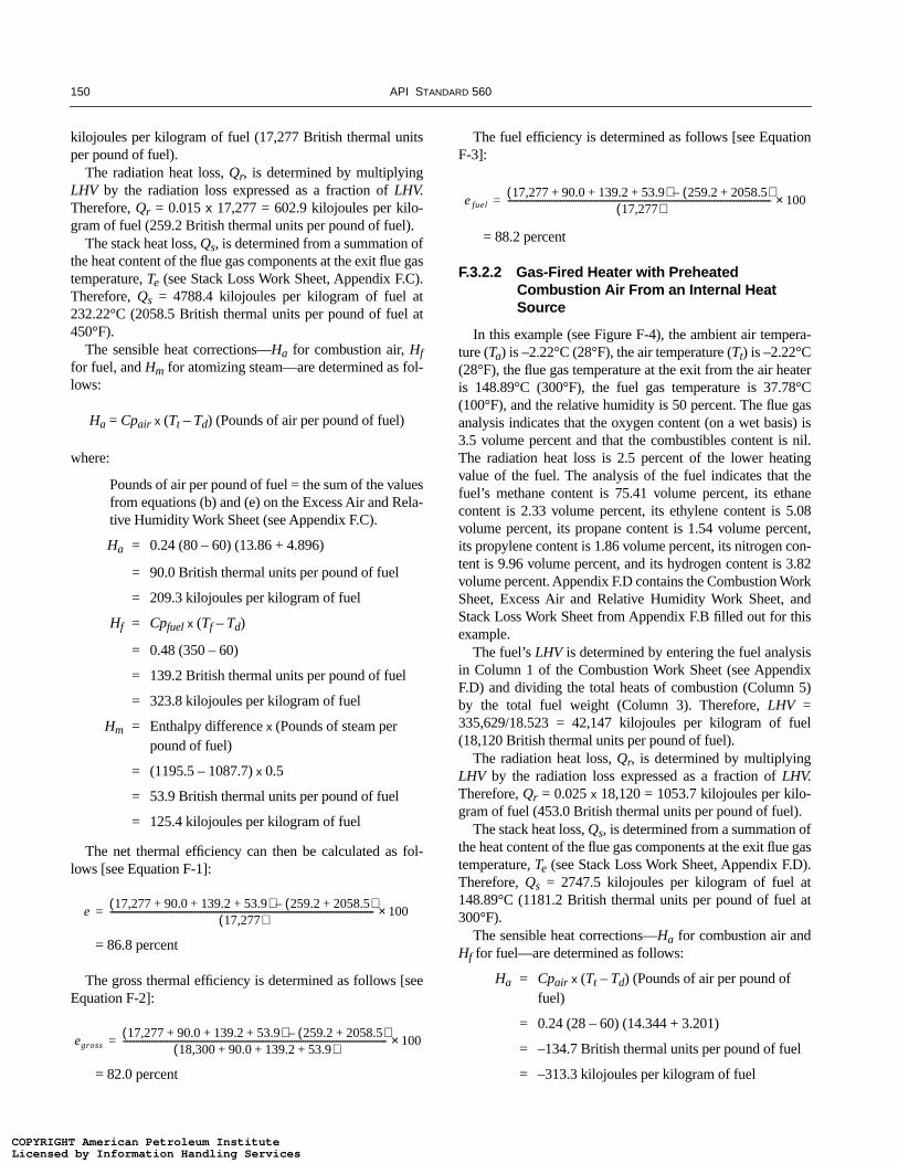
150 API STANDARD 560
kilojoules per kilogram of fuel (17,277 British thermal unitsper pound of fuel).
The radiation heat loss, Qr, is determined by multiplyingLHV by the radiation loss expressed as a fraction of LHV.Therefore, Qr = 0.015 x 17,277 = 602.9 kilojoules per kilo-gram of fuel (259.2 British thermal units per pound of fuel).
The stack heat loss, Qs, is determined from a summation ofthe heat content of the flue gas components at the exit flue gastemperature, Te (see Stack Loss Work Sheet, Appendix F.C).Therefore, Qs = 4788.4 kilojoules per kilogram of fuel at232.22°C (2058.5 British thermal units per pound of fuel at450°F).
The sensible heat corrections—Ha for combustion air, Hffor fuel, and Hm for atomizing steam—are determined as fol-lows:
Ha = Cpair x (Tt – Td) (Pounds of air per pound of fuel)
where:
Pounds of air per pound of fuel = the sum of the valuesfrom equations (b) and (e) on the Excess Air and Rela-tive Humidity Work Sheet (see Appendix F.C).
Ha = 0.24 (80 – 60) (13.86 + 4.896)
= 90.0 British thermal units per pound of fuel
= 209.3 kilojoules per kilogram of fuel
Hf = Cpfuel x (Tf – Td)
= 0.48 (350 – 60)
= 139.2 British thermal units per pound of fuel
= 323.8 kilojoules per kilogram of fuel
Hm = Enthalpy difference x (Pounds of steam per pound of fuel)
= (1195.5 – 1087.7) x 0.5
= 53.9 British thermal units per pound of fuel
= 125.4 kilojoules per kilogram of fuel
The net thermal efficiency can then be calculated as fol-lows [see Equation F-1]:
= 86.8 percent
The gross thermal efficiency is determined as follows [seeEquation F-2]:
= 82.0 percent
The fuel efficiency is determined as follows [see EquationF-3]:
= 88.2 percent
F.3.2.2 Gas-Fired Heater with Preheated Combustion Air From an Internal Heat Source
In this example (see Figure F-4), the ambient air tempera-ture (Ta) is –2.22°C (28°F), the air temperature (Tt) is –2.22°C(28°F), the flue gas temperature at the exit from the air heateris 148.89°C (300°F), the fuel gas temperature is 37.78°C(100°F), and the relative humidity is 50 percent. The flue gasanalysis indicates that the oxygen content (on a wet basis) is3.5 volume percent and that the combustibles content is nil.The radiation heat loss is 2.5 percent of the lower heatingvalue of the fuel. The analysis of the fuel indicates that thefuel’s methane content is 75.41 volume percent, its ethanecontent is 2.33 volume percent, its ethylene content is 5.08volume percent, its propane content is 1.54 volume percent,its propylene content is 1.86 volume percent, its nitrogen con-tent is 9.96 volume percent, and its hydrogen content is 3.82volume percent. Appendix F.D contains the Combustion WorkSheet, Excess Air and Relative Humidity Work Sheet, andStack Loss Work Sheet from Appendix F.B filled out for thisexample.
The fuel’s LHV is determined by entering the fuel analysisin Column 1 of the Combustion Work Sheet (see AppendixF.D) and dividing the total heats of combustion (Column 5)by the total fuel weight (Column 3). Therefore, LHV =335,629/18.523 = 42,147 kilojoules per kilogram of fuel(18,120 British thermal units per pound of fuel).
The radiation heat loss, Qr, is determined by multiplyingLHV by the radiation loss expressed as a fraction of LHV.Therefore, Qr = 0.025 x 18,120 = 1053.7 kilojoules per kilo-gram of fuel (453.0 British thermal units per pound of fuel).
The stack heat loss, Qs, is determined from a summation ofthe heat content of the flue gas components at the exit flue gastemperature, Te (see Stack Loss Work Sheet, Appendix F.D).Therefore, Qs = 2747.5 kilojoules per kilogram of fuel at148.89°C (1181.2 British thermal units per pound of fuel at300°F).
The sensible heat corrections—Ha for combustion air andHf for fuel—are determined as follows:
Ha = Cpair x (Tt – Td) (Pounds of air per pound of fuel)
= 0.24 (28 – 60) (14.344 + 3.201)
= –134.7 British thermal units per pound of fuel
= –313.3 kilojoules per kilogram of fuel
e17,277 90.0 139.2 53.9+ + +( ) 259.2 2058.5+( )–
17,277( )------------------------------------------------------------------------------------------------------------------------ 100×=
egross17,277 90.0 139.2 53.9+ + +( ) 259.2 2058.5+( )–
18,300 90.0 139.2 53.9+ + +( )------------------------------------------------------------------------------------------------------------------------ 100×=
e fuel17,277 90.0 139.2 53.9+ + +( ) 259.2 2058.5+( )–
17,277( )------------------------------------------------------------------------------------------------------------------------ 100×=
COPYRIGHT American Petroleum InstituteLicensed by Information Handling ServicesCOPYRIGHT American Petroleum InstituteLicensed by Information Handling Services
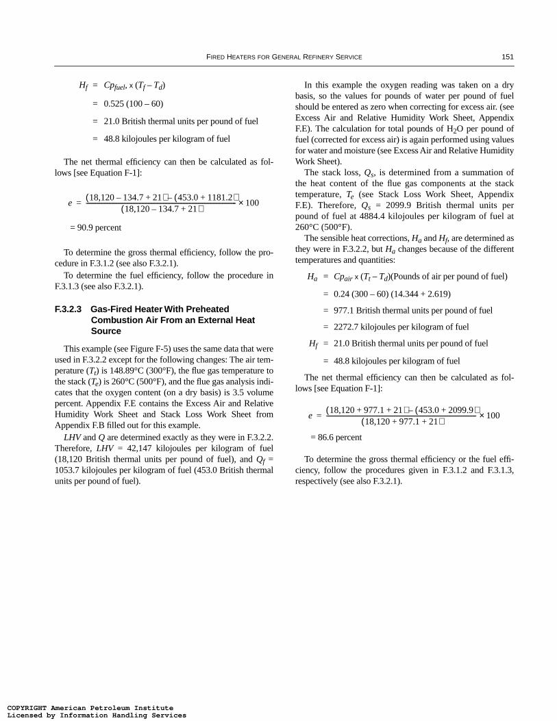
FIRED HEATERS FOR GENERAL REFINERY SERVICE 151
Hf = Cpfuel, x (Tf – Td)
= 0.525 (100 – 60)
= 21.0 British thermal units per pound of fuel
= 48.8 kilojoules per kilogram of fuel
The net thermal efficiency can then be calculated as fol-lows [see Equation F-1]:
= 90.9 percent
To determine the gross thermal efficiency, follow the pro-cedure in F.3.1.2 (see also F.3.2.1).
To determine the fuel efficiency, follow the procedure inF.3.1.3 (see also F.3.2.1).
F.3.2.3 Gas-Fired Heater With Preheated Combustion Air From an External Heat Source
This example (see Figure F-5) uses the same data that wereused in F.3.2.2 except for the following changes: The air tem-perature (Tt) is 148.89°C (300°F), the flue gas temperature tothe stack (Te) is 260°C (500°F), and the flue gas analysis indi-cates that the oxygen content (on a dry basis) is 3.5 volumepercent. Appendix F.E contains the Excess Air and RelativeHumidity Work Sheet and Stack Loss Work Sheet fromAppendix F.B filled out for this example.
LHV and Q are determined exactly as they were in F.3.2.2.Therefore, LHV = 42,147 kilojoules per kilogram of fuel(18,120 British thermal units per pound of fuel), and Qf =1053.7 kilojoules per kilogram of fuel (453.0 British thermalunits per pound of fuel).
In this example the oxygen reading was taken on a drybasis, so the values for pounds of water per pound of fuelshould be entered as zero when correcting for excess air. (seeExcess Air and Relative Humidity Work Sheet, AppendixF.E). The calculation for total pounds of H2O per pound offuel (corrected for excess air) is again performed using valuesfor water and moisture (see Excess Air and Relative HumidityWork Sheet).
The stack loss, Qs, is determined from a summation ofthe heat content of the flue gas components at the stacktemperature, Te (see Stack Loss Work Sheet, AppendixF.E). Therefore, Qs = 2099.9 British thermal units perpound of fuel at 4884.4 kilojoules per kilogram of fuel at260°C (500°F).
The sensible heat corrections, Ha and Hf, are determined asthey were in F.3.2.2, but Ha changes because of the differenttemperatures and quantities:
Ha = Cpair x (Tt – Td)(Pounds of air per pound of fuel)
= 0.24 (300 – 60) (14.344 + 2.619)
= 977.1 British thermal units per pound of fuel
= 2272.7 kilojoules per kilogram of fuel
Hf = 21.0 British thermal units per pound of fuel
= 48.8 kilojoules per kilogram of fuel
The net thermal efficiency can then be calculated as fol-lows [see Equation F-1]:
= 86.6 percent
To determine the gross thermal efficiency or the fuel effi-ciency, follow the procedures given in F.3.1.2 and F.3.1.3,respectively (see also F.3.2.1).
e18,120 134.7– 21+( ) 453.0 1181.2+( )–
18,120 134.7– 21+( )--------------------------------------------------------------------------------------------------- 100×=
e18,120 977.1 21+ +( ) 453.0 2099.9+( )–
18,120 977.1 21+ +( )--------------------------------------------------------------------------------------------------- 100×=
COPYRIGHT American Petroleum InstituteLicensed by Information Handling ServicesCOPYRIGHT American Petroleum InstituteLicensed by Information Handling Services

COPYRIGHT American Petroleum InstituteLicensed by Information Handling ServicesCOPYRIGHT American Petroleum InstituteLicensed by Information Handling Services

153
APPENDIX F.A—MODEL FORMAT FOR DATA SHEETS
COPYRIGHT American Petroleum InstituteLicensed by Information Handling ServicesCOPYRIGHT American Petroleum InstituteLicensed by Information Handling Services

COPYRIGHT American Petroleum InstituteLicensed by Information Handling ServicesCOPYRIGHT American Petroleum InstituteLicensed by Information Handling Services

155
Laboratory Data SheetJob No. ________________________________________________Date of Report __________________________________________Page
I. GENERAL INFORMATION
Owner: _________________________________________________ Plant location: __________________________________________Unit: __________________________________________________ Site elevation: ___________________________________________Heater no.: ______________________________________________ Service: _______________________________________________
Test run date:Test run time:Run no.:
II. FUEL GAS SAMPLESample taken by:Sample no.:Sampling location:Date taken:Time taken:
Fuel gas analysis, volume percentHydrogen:Methane:Ethane:Other C2:Propane:Other C3:Butane:Other C4:Pentane plus:Carbon monoxide:Hydrogen sulfide:Carbon dioxide:Nitrogen:Oxygen:Other inerts:
Total:
Remarks: ______________________________________________________________________________________________________________________________________________________________________________________________________________________________________________________________________________________________________________________________________________
III. FUEL OIL SAMPLE
________________________ of _______________________1 2
COPYRIGHT American Petroleum InstituteLicensed by Information Handling ServicesCOPYRIGHT American Petroleum InstituteLicensed by Information Handling Services

156
Sample taken by:Sample no.:Sampling location:Date taken:Time taken:Sample temperature, °F:
Analysis, weight percentCarbon:Hydrogen:
Laboratory Data SheetJob No. ________________________________________________Date of Report __________________________________________Page
Carbon-hydrogen ratio:*Sulfur:Ash:Nitrogen:Oxygen:Water:Other:
Total:Calorimeter heating value:Vanadium, parts per million:Sodium, parts per million:Gravity, °API:Additive used:
IV. PROCESS STREAM SAMPLESample taken by:Sample no.:Sampling location:Date taken:Time taken:
Sample test conditionsTemperature, °F:Pressure, psig:Name of fluid:Liquid gravity, °API:Vapor molecular weight:
ASTM liquid distillationInitial boiling point:10 percent vaporized:20 percent vaporized:30 percent vaporized:40 percent vaporized:50 percent vaporized:
60 percent vaporized:
70 percent vaporized:
________________________ of _______________________2 2
COPYRIGHT American Petroleum InstituteLicensed by Information Handling ServicesCOPYRIGHT American Petroleum InstituteLicensed by Information Handling Services

157
80 percent vaporized:
90 percent vaporized:Endpoint:
V. GENERAL CONDITIONS________________________________________________________________________________________________________________________________________________________________________________________________________________________________________________________________________________________________________________________________________________________________________________________________________________________________________________________________________Remarks: ______________________________________________________________________________________________________________________________________________________________________________________________________________________________________________________________________________________________________________________________________________*May be entered instead of carbon and hydrogen contents.
Raw Test Data SheetJob No. _______________________________________________Date of Report _________________________________________Page
I. GENERAL INFORMATION
Owner: _______________________________________________ Plant location: _________________________________________
Unit: _________________________________________________ Site elevation: _________________________________________
Heater no.: _____________________________________________ Service: ______________________________________________
Manufacturer: _____________________________________________________________________________________________________
Test run date:
Test run time:
Run no.:
Recorded by:
II. GENERAL CONDITIONS
Ambient air temperature, °F:
Wind direction:
Wind velocity, miles per hour:
Plant barometric pressure, inches Hg:
Radiation loss. percent
Relative humidity, percent:
III. COMBUSTION DATA
Fuel gas
Flow meter reading:
Flow meter factor and data base:
Pressure at flow meter, psig:
Temperature at flow meter, °F:
Pressure at burners, psig:
________________________ of _______________________1 3
COPYRIGHT American Petroleum InstituteLicensed by Information Handling ServicesCOPYRIGHT American Petroleum InstituteLicensed by Information Handling Services
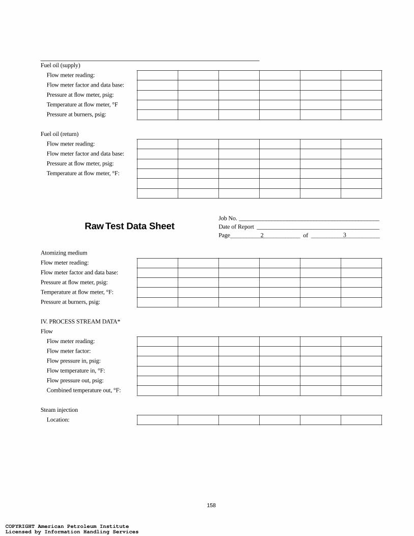
158
Fuel oil (supply)
Flow meter reading:
Flow meter factor and data base:
Pressure at flow meter, psig:
Temperature at flow meter, °F
Pressure at burners, psig:
Fuel oil (return)
Flow meter reading:
Flow meter factor and data base:
Pressure at flow meter, psig:
Temperature at flow meter, °F:
Raw Test Data SheetJob No. _______________________________________________Date of Report _________________________________________Page
Atomizing medium
Flow meter reading:
Flow meter factor and data base:
Pressure at flow meter, psig:
Temperature at flow meter, °F:
Pressure at burners, psig:
IV. PROCESS STREAM DATA*
Flow
Flow meter reading:
Flow meter factor:
Flow pressure in, psig:
Flow temperature in, °F:
Flow pressure out, psig:
Combined temperature out, °F:
Steam injection
Location:
________________________ of _______________________2 3
COPYRIGHT American Petroleum InstituteLicensed by Information Handling ServicesCOPYRIGHT American Petroleum InstituteLicensed by Information Handling Services

159
Total consumption, pounds per hour:
V. AIR AND FLUE GAS DATA
Pressure, inches H2O
Draft at burners:
Draft at firebox roof:
*Similar data should be recorded for secondary streams such as boiler feed water, steam generation, and steam superheat.
Raw Test Data SheetJob No. _______________________________________Date of Report _________________________________Page
Run No. Run No. Run No.
Temperature, °F TraverseReadings
Aver-age
TraverseReadings
Aver-age
TraverseReadings
Aver-age
Air into preheater:
Air out of preheater:
Flue gas out of preheater:†
Flue gas in stack:†
Flue gas analysis, volume percent
Oxygen content:†
Combustibles and carbon monoxide:
VI. ASSOCIATED EQUIPMENT
Air heater
Nameplate size:
____________________ of __________________3 3
COPYRIGHT American Petroleum InstituteLicensed by Information Handling ServicesCOPYRIGHT American Petroleum InstituteLicensed by Information Handling Services
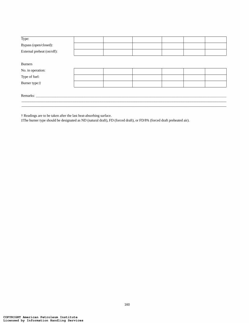
160
Type:
Bypass (open/closed):
External preheat (on/off):
Burners
No. in operation:
Type of fuel:
Burner type:‡
Remarks: ______________________________________________________________________________________________________________________________________________________________________________________________________________________________________________________________________________________________________________________________________________
† Readings are to be taken after the last heat-absorbing surface.‡The burner type should be designated as ND (natural draft), FD (forced draft), or FD/PA (forced draft preheated air).
COPYRIGHT American Petroleum InstituteLicensed by Information Handling ServicesCOPYRIGHT American Petroleum InstituteLicensed by Information Handling Services

161
APPENDIX F.B—MODEL FORMAT FOR WORK SHEETS
COPYRIGHT American Petroleum InstituteLicensed by Information Handling ServicesCOPYRIGHT American Petroleum InstituteLicensed by Information Handling Services

COPYRIGHT American Petroleum InstituteLicensed by Information Handling ServicesCOPYRIGHT American Petroleum InstituteLicensed by Information Handling Services

163
LOWER HEATING VALUE (LIQUID FUELS) WORK SHEET
Job No. _______________________________________________Date of Report _________________________________________Page
Higher heating value (HHV), from calorimeter test, in British thermal units per pound of fuel:
Carbon-hydrogen ration, from analysis:
Impurities, from analysis, weight percent
Water vapor:
Ash:
Sulfur:
Sodium:
Other:
Total:
Percent hydrogen =
LHV = HHV – (9 x 1059.7) , in British thermal units per pound of fuel:
Percent carbon = 100 – (Percent hydrogen + Percent impurities):
INSTRUCTIONS
Calculate the values for percent hydrogen, lower heating value (LHV), and percent carbon. Enter these values in the appropriate columns of the Combustion Work Sheet.
________________________ of _______________________1 1
100 Weight percent impurities–Carbon-hydrogen ratio 1.0+
-----------------------------------------------------------------------------
Percent hydrogen100
------------------------------------------
COPYRIGHT American Petroleum InstituteLicensed by Information Handling ServicesCOPYRIGHT American Petroleum InstituteLicensed by Information Handling Services
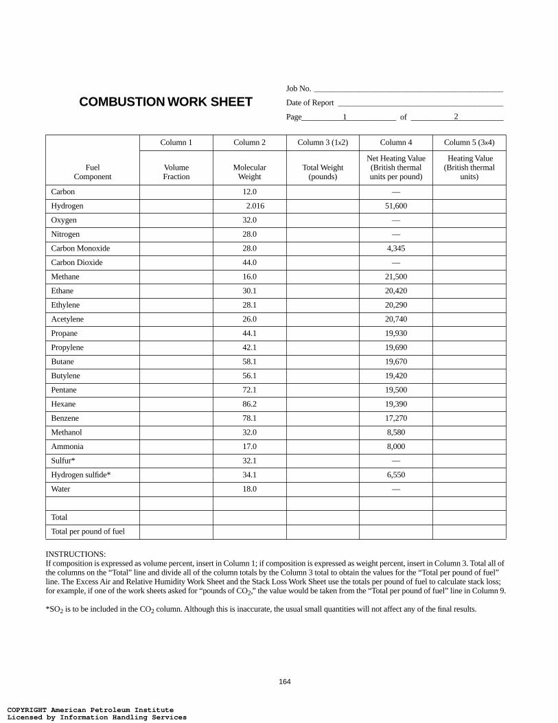
164
COMBUSTION WORK SHEETJob No. _______________________________________________
Date of Report _________________________________________
Page
FuelComponent
Column 1 Column 2 Column 3 (1x2) Column 4 Column 5 (3x4)
VolumeFraction
MolecularWeight
Total Weight(pounds)
Net Heating Value (British thermalunits per pound)
Heating Value(British thermal
units)
Carbon 12.0 —
Hydrogen 2.016 51,600
Oxygen 32.0 —
Nitrogen 28.0 —
Carbon Monoxide 28.0 4,345
Carbon Dioxide 44.0 —
Methane 16.0 21,500
Ethane 30.1 20,420
Ethylene 28.1 20,290
Acetylene 26.0 20,740
Propane 44.1 19,930
Propylene 42.1 19,690
Butane 58.1 19,670
Butylene 56.1 19,420
Pentane 72.1 19,500
Hexane 86.2 19,390
Benzene 78.1 17,270
Methanol 32.0 8,580
Ammonia 17.0 8,000
Sulfur* 32.1 —
Hydrogen sulfide* 34.1 6,550
Water 18.0 —
Total
Total per pound of fuel
INSTRUCTIONS:If composition is expressed as volume percent, insert in Column 1; if composition is expressed as weight percent, insert in Column 3. Total all of the columns on the “Total” line and divide all of the column totals by the Column 3 total to obtain the values for the “Total per pound of fuel” line. The Excess Air and Relative Humidity Work Sheet and the Stack Loss Work Sheet use the totals per pound of fuel to calculate stack loss; for example, if one of the work sheets asked for “pounds of CO2,” the value would be taken from the “Total per pound of fuel” line in Column 9.
*SO2 is to be included in the CO2 column. Although this is inaccurate, the usual small quantities will not affect any of the final results.
________________________ of _______________________1 2
COPYRIGHT American Petroleum InstituteLicensed by Information Handling ServicesCOPYRIGHT American Petroleum InstituteLicensed by Information Handling Services

165
COMBUSTION WORK SHEETJob No. _________________________________________________
Date of Report ___________________________________________
Page
Column 6 Column 7 (3x6)
Column 8 Column 9 (3x8)
Column 10 Column 11 (3x10)
Column 12 Column 13 (3x12)
Air Required (pounds of air
per pound)Air Required
(pounds)
CO2 Formed (pounds of CO2 per pound)
CO2 Formed (pounds)
H20 Formed (pounds of H2O per pound)
H20 Formed (pounds)
N2 Formed (pounds of N2
per pound)N2 Formed (pounds)
11.51 3.66 — 8.85
34.29 — 8.94 26.36
–4.32 — — –3.32
— — — 1.00
2.47 1.57 — 1.90
— 1.00 — —
17.24 2.74 2.25 13.25
16.09 2.93 1.80 12.37
14.79 3.14 1.28 11.36
13.29 3.38 0.69 10.21
15.68 2.99 1.63 12.05
14.79 3.14 1.28 11.36
15.46 3.03 1.55 11.88
14.79 3.14 1.28 11.36
15.33 3.05 1.50 11.78
15.24 3.06 1.46 11.71
13.27 3.38 0.69 10.20
6.48 1.38 1.13 4.98
6.10 — 1.59 5.51
4.31 2.00 — 3.31
6.08 1.88 0.53 4.68
— — 1.00 —
__________________________ of _______________________2 2
COPYRIGHT American Petroleum InstituteLicensed by Information Handling ServicesCOPYRIGHT American Petroleum InstituteLicensed by Information Handling Services
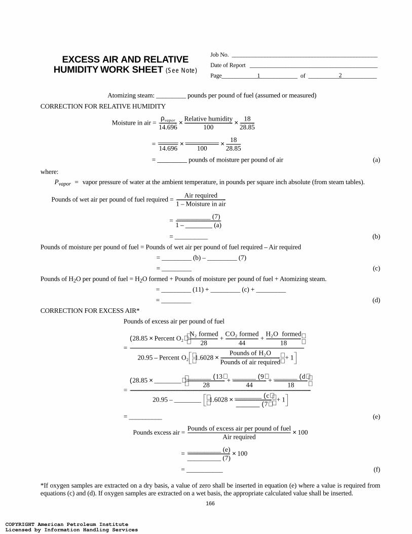
166
Atomizing steam: _________ pounds per pound of fuel (assumed or measured)
CORRECTION FOR RELATIVE HUMIDITY
Moisture in air =
=
= _________ pounds of moisture per pound of air (a)
where:
Pvapor = vapor pressure of water at the ambient temperature, in pounds per square inch absolute (from steam tables).
Pounds of wet air per pound of fuel required =
=
= __________ (b)
Pounds of moisture per pound of fuel = Pounds of wet air per pound of fuel required – Air required
= _________ (b) – _________ (7)
= _________ (c)
Pounds of H2O per pound of fuel = H2O formed + Pounds of moisture per pound of fuel + Atomizing steam.
= _________ (11) + _________ (c) + _________
= _________ (d)
CORRECTION FOR EXCESS AIR*
Pounds of excess air per pound of fuel
=
=
= __________ (e)
Pounds excess air =
=
= ___________ (f)
*If oxygen samples are extracted on a dry basis, a value of zero shall be inserted in equation (e) where a value is required fromequations (c) and (d). If oxygen samples are extracted on a wet basis, the appropriate calculated value shall be inserted.
EXCESS AIR AND RELATIVE HUMIDITY WORK SHEET (See Note)
Job No. _________________________________________________
Date of Report ___________________________________________
Page__________________________ of _______________________1 2
ρvapor
14.696----------------
Relative humidity100
-------------------------------------------× 1828.85-------------×
______14.696------------------
__________100
------------------------------× 1828.85-------------×
Air required1 Moisture in air–--------------------------------------------
__________ (7)1 ________ (a)–----------------------------------------
28.85 Percent O2×( )N2 formed
28-------------------------
CO2 formed44
-----------------------------H2O formed
18-------------------------------+ +
20.95 Percent O2 1.6028Pounds of H2O
Pounds of air required-----------------------------------------------------×
1+–
-----------------------------------------------------------------------------------------------------------------------------------------------------------
28.85 ________×( ) _______ 13( )28
---------------------------------_______ 9( )
44------------------------------
_______ d( )18
------------------------------+ +
20.95 ________ 1.6028________ c( )_______ 7( )---------------------------------×
1+–
-----------------------------------------------------------------------------------------------------------------------------------------------------------------
Pounds of excess air per pound of fuelAir required
-------------------------------------------------------------------------------------------- 100×
__________ (e)__________ (7)-------------------------------------- 100×
COPYRIGHT American Petroleum InstituteLicensed by Information Handling ServicesCOPYRIGHT American Petroleum InstituteLicensed by Information Handling Services

167
Total pounds of H2O per pound of fuel (corrected for excess air)
= + Pounds of H2O per pound of fuel
= + _________ (d)
= _________ (g)
Note: All values used in the calculations above shall be on a per-pound-of-fuel basis. Numbers in parentheses indicate values tobe taken from the “Total per pound of fuel” line of the Combustion Work Sheet, and letters in parentheses indicate values to betaken from the corresponding lines of this work sheet.
EXCESS AIR AND RELATIVE HUMIDITY WORK SHEET (See Note)
Job No. _________________________________________________
Date of Report ___________________________________________
Page__________________________ of _______________________2 2
Percent excess air100
------------------------------------------- Pounds of moisture per pound of fuel×
_________ f( )100
---------------------------------- _________ c( )×
COPYRIGHT American Petroleum InstituteLicensed by Information Handling ServicesCOPYRIGHT American Petroleum InstituteLicensed by Information Handling Services
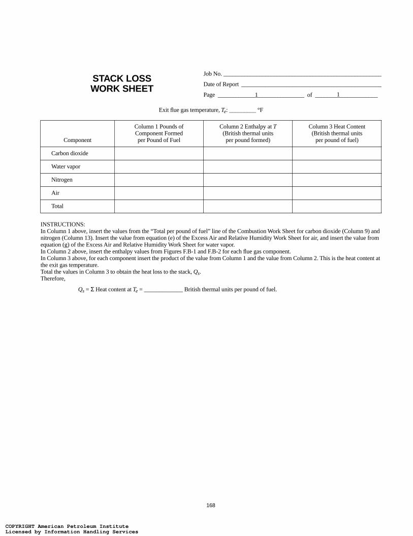
168
STACK LOSSWORK SHEET
Job No. _____________________________________________________
Date of Report _______________________________________________
Page
Exit flue gas temperature, Te: _________ °F
Component
Column 1 Pounds of Component Formed per Pound of Fuel
Column 2 Enthalpy at T (British thermal units
per pound formed)
Column 3 Heat Content (British thermal units
per pound of fuel)
Carbon dioxide
Water vapor
Nitrogen
Air
Total
INSTRUCTIONS:In Column 1 above, insert the values from the “Total per pound of fuel” line of the Combustion Work Sheet for carbon dioxide (Column 9) and nitrogen (Column 13). Insert the value from equation (e) of the Excess Air and Relative Humidity Work Sheet for air, and insert the value from equation (g) of the Excess Air and Relative Humidity Work Sheet for water vapor.In Column 2 above, insert the enthalpy values from Figures F.B-1 and F.B-2 for each flue gas component.In Column 3 above, for each component insert the product of the value from Column 1 and the value from Column 2. This is the heat content at the exit gas temperature.Total the values in Column 3 to obtain the heat loss to the stack, Qs.Therefore,
Qs = Σ Heat content at Te = _____________ British thermal units per pound of fuel.
_____________________________ of _____________________1 1
COPYRIGHT American Petroleum InstituteLicensed by Information Handling ServicesCOPYRIGHT American Petroleum InstituteLicensed by Information Handling Services

169
200 300 400 500 600 700 800 1000 1100 1200 1300 1400 1500 1600
1000
900
800
700
600
500
400
300
200
100
0
Figure G.B-1—Enthalpy of H2O, CO, CO2 and SO2
900
TEMPERATURE, °F
EN
TH
AL
PY
AB
OV
E 60°F
, BT
U/L
B
Sulfur dioxideCarbon dioxideCarbon monoxide
Water vapor
Note: This figure is taken from the Technical Data Book—Petroleum Refining (English edition), Chapter 14, “Combustion,” p. 14-25, API, Washington, D.C., 1966.
Figure F.B-1—Enthalpy of H2O, CO, CO2, and SO2
COPYRIGHT American Petroleum InstituteLicensed by Information Handling ServicesCOPYRIGHT American Petroleum InstituteLicensed by Information Handling Services

170
200 300 400 500 600 700 800 1000 1100 1200 1300 1400 1500 1600
500
450
400
350
300
250
200
150
100
50
0900
TEMPERATURE, °F
EN
TH
AL
PY
AB
OV
E 60°F
, BT
U/L
B
Air
Oxygen
Nitrogen
Note: This figure is taken from the Technical Data Book—Petroleum Refining (English edition), Chapter 14, “Combustion,” p. 14-25, API, Washington, D.C., 1966.
Figure F.B-2—Enthalpy of Air, O2, and N2
COPYRIGHT American Petroleum InstituteLicensed by Information Handling ServicesCOPYRIGHT American Petroleum InstituteLicensed by Information Handling Services

171
APPENDIX F.C—SAMPLE WORK SHEETS FOR AN OIL-FIRED HEATER WITH NATURAL DRAFT
COPYRIGHT American Petroleum InstituteLicensed by Information Handling ServicesCOPYRIGHT American Petroleum InstituteLicensed by Information Handling Services

COPYRIGHT American Petroleum InstituteLicensed by Information Handling ServicesCOPYRIGHT American Petroleum InstituteLicensed by Information Handling Services
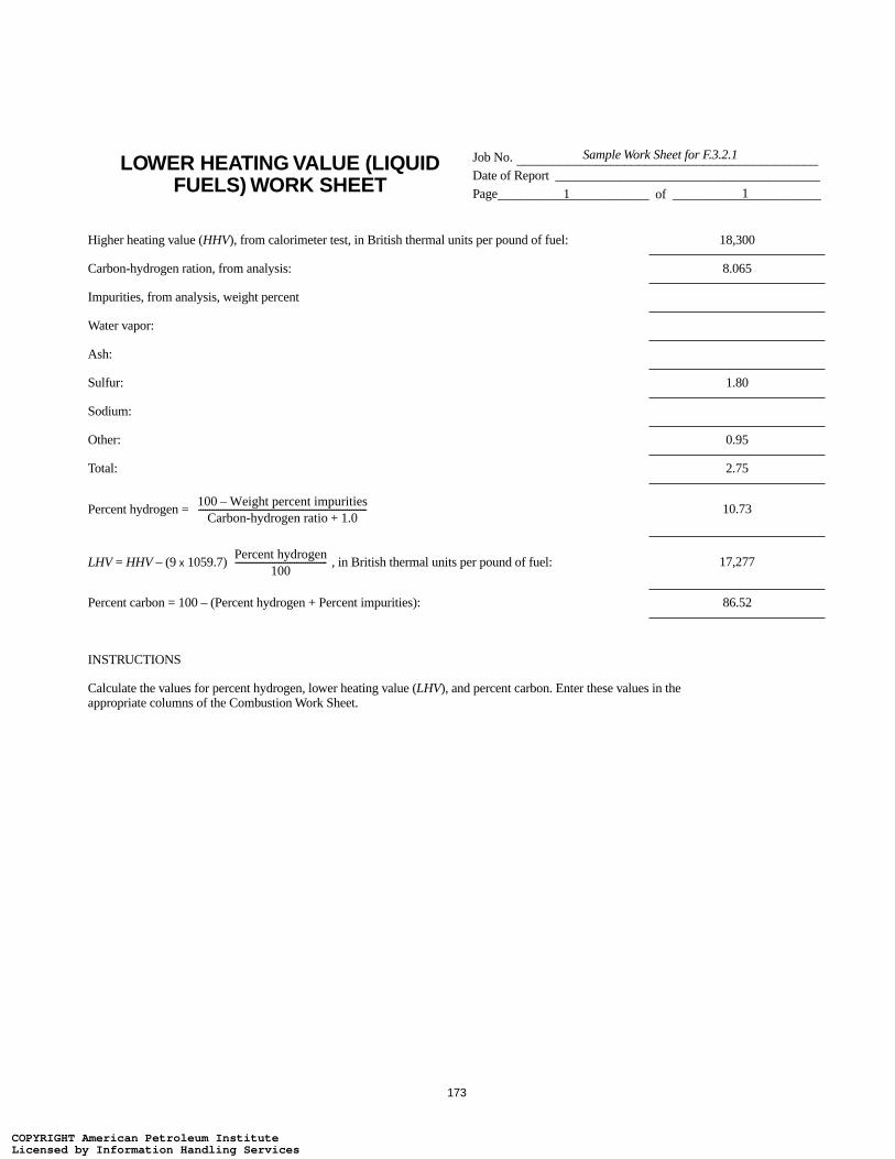
173
LOWER HEATING VALUE (LIQUID FUELS) WORK SHEET
Job No. Date of Report _________________________________________Page
Higher heating value (HHV), from calorimeter test, in British thermal units per pound of fuel: 18,300
Carbon-hydrogen ration, from analysis: 8.065
Impurities, from analysis, weight percent
Water vapor:
Ash:
Sulfur: 1.80
Sodium:
Other: 0.95
Total: 2.75
Percent hydrogen = 10.73
LHV = HHV – (9 x 1059.7) , in British thermal units per pound of fuel: 17,277
Percent carbon = 100 – (Percent hydrogen + Percent impurities): 86.52
INSTRUCTIONS
Calculate the values for percent hydrogen, lower heating value (LHV), and percent carbon. Enter these values in the appropriate columns of the Combustion Work Sheet.
__________________________________________Sample Work Sheet for F.3.2.1
________________________ of _______________________1 1
100 Weight percent impurities–Carbon-hydrogen ratio 1.0+
-----------------------------------------------------------------------------
Percent hydrogen100
------------------------------------------
COPYRIGHT American Petroleum InstituteLicensed by Information Handling ServicesCOPYRIGHT American Petroleum InstituteLicensed by Information Handling Services

174
COMBUSTION WORK SHEETJob No.
Date of Report _________________________________________
Page
FuelComponent
Column 1 Column 2 Column 3 (1x2) Column 4 Column 5 (3x4)
VolumeFraction
MolecularWeight
Total Weight(pounds)
Net Heating Value (British thermalunits per pound)
Heating Value(British thermal
units)
Carbon 12.0 0.8652 —
Hydrogen 2.016 0.1073 51,600
Oxygen 32.0 —
Nitrogen 28.0 —
Carbon Monoxide 28.0 4,345
Carbon Dioxide 44.0 —
Methane 16.0 21,500
Ethane 30.1 20,420
Ethylene 28.1 20,290
Acetylene 26.0 20,740
Propane 44.1 19,930
Propylene 42.1 19,690
Butane 58.1 19,670
Butylene 56.1 19,420
Pentane 72.1 19,500
Hexane 86.2 19,390
Benzene 78.1 17,270
Methanol 32.0 8,580
Ammonia 17.0 8,000
Sulfur* 32.1 0.0180 —
Hydrogen sulfide* 34.1 6,550
Water 18.0 —
Inerts 0.0095
Total 1.0000
Total per pound of fuel 1.0000
INSTRUCTIONSIf composition is expressed as volume percent, insert in Column 1; if composition is expressed as weight percent, insert in Column 3. Total all of the columns on the “Total” line and divide all of the column totals by the Column 3 total to obtain the values for the “Total per pound of fuel” line. The Excess Air and Relative Humidity Work Sheet and the Stack Loss Work Sheet use the totals per pound of fuel to calculate stack loss; for example, if one of the work sheets asked for “pounds of CO2,” the value would be taken from the “Total per pound of fuel” line in Column 9.
*SO2 is to be included in the CO2 column. Although this is inaccurate, the usual small quantities will not affect any of the final results.
__________________________________________Sample Work Sheet for F.3.2.1
________________________ of _______________________1 2
COPYRIGHT American Petroleum InstituteLicensed by Information Handling ServicesCOPYRIGHT American Petroleum InstituteLicensed by Information Handling Services

175
COMBUSTION WORK SHEETJob No.
Date of Report ___________________________________________
Page
Column 6 Column 7 (3x6)
Column 8 Column 9 (3x8)
Column 10 Column 11 (3x10)
Column 12 Column 13 (3x12)
Air Required (pounds of air
per pound)Air Required
(pounds)
CO2 Formed (pounds of CO2 per pound)
CO2 Formed (pounds)
H2O Formed (pounds of H2O per pound)
H2O Formed (pounds)
N2 Formed (pounds of N2
per pound)N2 Formed (pounds)
11.51 3.66 3.167 — 8.85 7.657
34.29 — — 8.94 26.36 2.828
–4.32 — — –3.32
— — — 1.00
2.47 1.57 — 1.90
— 1.00 — —
17.24 2.74 2.25 13.25
16.09 2.93 1.80 12.37
14.79 3.14 1.28 11.36
13.29 3.38 0.69 10.21
15.68 2.99 1.63 12.05
14.79 3.14 1.28 11.36
15.46 3.03 1.55 11.88
14.79 3.14 1.28 11.36
15.33 3.05 1.50 11.78
15.24 3.06 1.46 11.71
13.27 3.38 0.69 10.20
6.48 1.38 1.13 4.98
6.10 — 1.59 5.51
4.31 0.078 2.00 0.036 — 3.31 0.060
6.08 1.88 0.53 4.68
— — 1.00 —
13.715 3.203 0.959 10.545
13.715 3.203 0.959 10.545
____________________________________________Sample Work Sheet for F.3.2.1
__________________________ of _______________________2 2
COPYRIGHT American Petroleum InstituteLicensed by Information Handling ServicesCOPYRIGHT American Petroleum InstituteLicensed by Information Handling Services
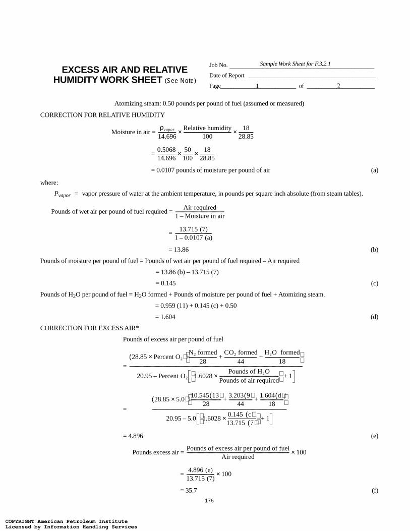
176
Atomizing steam: 0.50 pounds per pound of fuel (assumed or measured)
CORRECTION FOR RELATIVE HUMIDITY
Moisture in air =
=
= 0.0107 pounds of moisture per pound of air (a)
where:
Pvapor = vapor pressure of water at the ambient temperature, in pounds per square inch absolute (from steam tables).
Pounds of wet air per pound of fuel required =
=
= 13.86 (b)
Pounds of moisture per pound of fuel = Pounds of wet air per pound of fuel required – Air required
= 13.86 (b) – 13.715 (7)
= 0.145 (c)
Pounds of H2O per pound of fuel = H2O formed + Pounds of moisture per pound of fuel + Atomizing steam.
= 0.959 (11) + 0.145 (c) + 0.50
= 1.604 (d)
CORRECTION FOR EXCESS AIR*
Pounds of excess air per pound of fuel
=
=
= 4.896 (e)
Pounds excess air =
=
= 35.7 (f)
EXCESS AIR AND RELATIVE HUMIDITY WORK SHEET (See Note)
Job No.
Date of Report ___________________________________________
Page
____________________________________________Sample Work Sheet for F.3.2.1
__________________________ of _______________________1 2
ρvapor
14.696----------------
Relative humidity100
-------------------------------------------× 1828.85-------------×
0.506814.696----------------
50100---------× 18
28.85-------------×
Air required1 Moisture in air–--------------------------------------------
13.715 (7)1 0.0107 (a)–---------------------------------
28.85 Percent O2×( )N2 formed
28-------------------------
CO2 formed44
-----------------------------H2O formed
18-------------------------------+ +
20.95 Percent O2 1.6028Pounds of H2O
Pounds of air required-----------------------------------------------------×
1+–
-----------------------------------------------------------------------------------------------------------------------------------------------------------
28.85 5.0×( ) 10.545 13( )28
---------------------------3.203 9( )
44---------------------
1.604 d( )18
---------------------+ +
20.95 5.0 1.60280.145 c( )13.715 7( )-------------------------×
1+–
-------------------------------------------------------------------------------------------------------------------------
Pounds of excess air per pound of fuelAir required
-------------------------------------------------------------------------------------------- 100×
4.896 (e)13.715 (7)------------------------- 100×
COPYRIGHT American Petroleum InstituteLicensed by Information Handling ServicesCOPYRIGHT American Petroleum InstituteLicensed by Information Handling Services
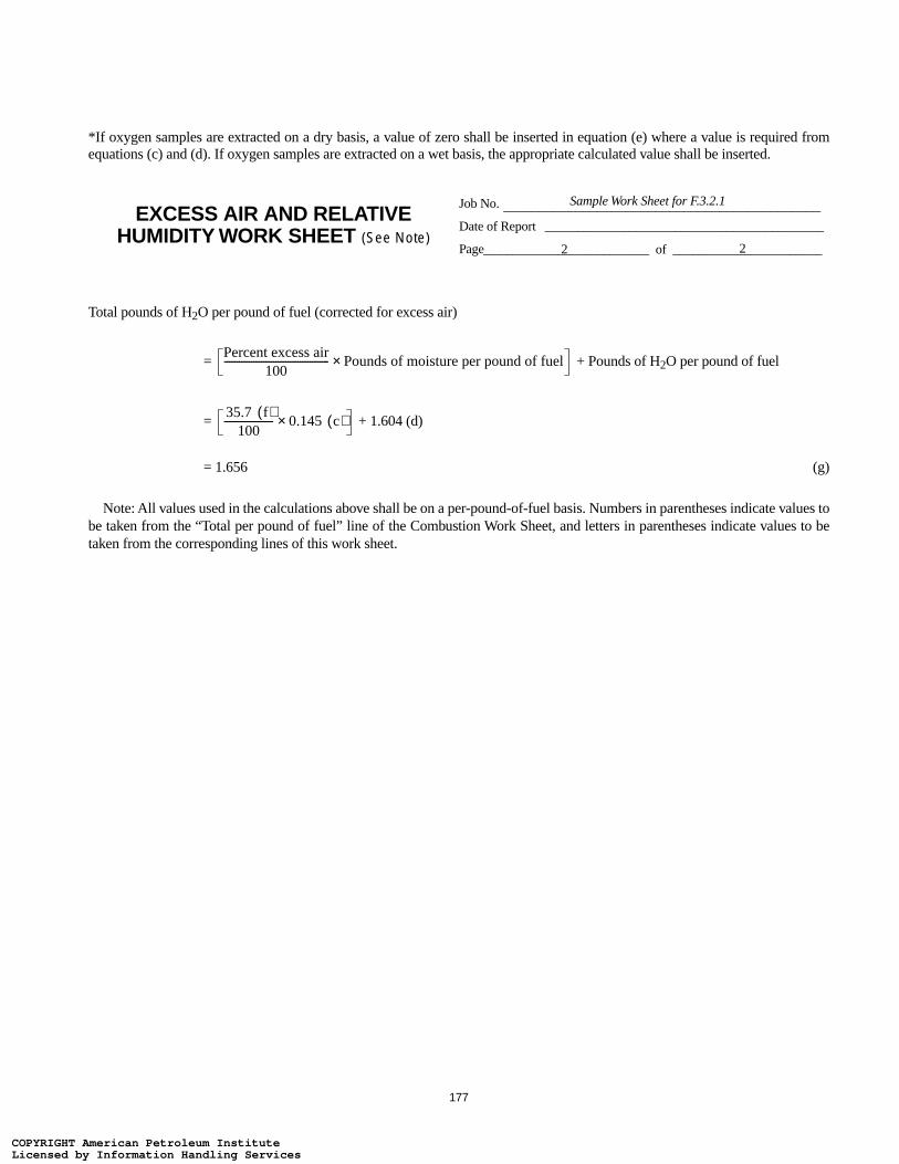
177
*If oxygen samples are extracted on a dry basis, a value of zero shall be inserted in equation (e) where a value is required fromequations (c) and (d). If oxygen samples are extracted on a wet basis, the appropriate calculated value shall be inserted.
Total pounds of H2O per pound of fuel (corrected for excess air)
= + Pounds of H2O per pound of fuel
= + 1.604 (d)
= 1.656 (g)
Note: All values used in the calculations above shall be on a per-pound-of-fuel basis. Numbers in parentheses indicate values tobe taken from the “Total per pound of fuel” line of the Combustion Work Sheet, and letters in parentheses indicate values to betaken from the corresponding lines of this work sheet.
EXCESS AIR AND RELATIVE HUMIDITY WORK SHEET (See Note)
Job No.
Date of Report ___________________________________________
Page
____________________________________________Sample Work Sheet for F.3.2.1
__________________________ of _______________________2 2
Percent excess air100
------------------------------------------- Pounds of moisture per pound of fuel×
35.7 f( )100
-------------------- 0.145 c( )×
COPYRIGHT American Petroleum InstituteLicensed by Information Handling ServicesCOPYRIGHT American Petroleum InstituteLicensed by Information Handling Services
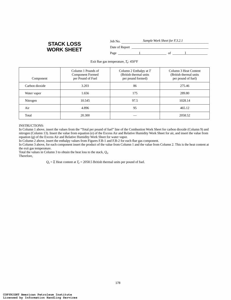
178
STACK LOSSWORK SHEET
Job No.
Date of Report ______________________________________________
Page
Exit flue gas temperature, Te: 450°F
Component
Column 1 Pounds of Component Formed per Pound of Fuel
Column 2 Enthalpy at T (British thermal units
per pound formed)
Column 3 Heat Content (British thermal units
per pound of fuel)
Carbon dioxide 3.203 86 275.46
Water vapor 1.656 175 289.80
Nitrogen 10.545 97.5 1028.14
Air 4.896 95 465.12
Total 20.300 — 2058.52
INSTRUCTIONS:In Column 1 above, insert the values from the “Total per pound of fuel” line of the Combustion Work Sheet for carbon dioxide (Column 9) and nitrogen (Column 13). Insert the value from equation (e) of the Excess Air and Relative Humidity Work Sheet for air, and insert the value from equation (g) of the Excess Air and Relative Humidity Work Sheet for water vapor.In Column 2 above, insert the enthalpy values from Figures F.B-1 and F.B-2 for each flue gas component.In Column 3 above, for each component insert the product of the value from Column 1 and the value from Column 2. This is the heat content at the exit gas temperature.Total the values in Column 3 to obtain the heat loss to the stack, Qs.Therefore,
Qs = Σ Heat content at Te = 2058.5 British thermal units per pound of fuel.
_______________________________________________Sample Work Sheet for F.3.2.1
_____________________________ of _____________________1 1
COPYRIGHT American Petroleum InstituteLicensed by Information Handling ServicesCOPYRIGHT American Petroleum InstituteLicensed by Information Handling Services

179
APPENDIX F.D—SAMPLE WORK SHEETS FOR A GAS-FIRED HEATER WITH PREHEATED COMBUSTION AIR FROM AN
INTERNAL HEAT SOURCE (F.3.2.2)
COPYRIGHT American Petroleum InstituteLicensed by Information Handling ServicesCOPYRIGHT American Petroleum InstituteLicensed by Information Handling Services

COPYRIGHT American Petroleum InstituteLicensed by Information Handling ServicesCOPYRIGHT American Petroleum InstituteLicensed by Information Handling Services

181
COMBUSTION WORK SHEETJob No.
Date of Report _________________________________________
Page
FuelComponent
Column 1 Column 2 Column 3 (1x2) Column 4 Column 5 (3x4)
VolumeFraction
MolecularWeight
Total Weight(pounds)
Net Heating Value (British thermalunits per pound)
Heating Value(British thermal
units)
Carbon 12.0 —
Hydrogen 0.0382 2.016 0.0770 51,600 3,973
Oxygen 32.0 —
Nitrogen 0.0996 28.0 2.789 — —
Carbon Monoxide 28.0 4,345
Carbon Dioxide 44.0 —
Methane 0.7541 16.0 12.066 21,500 259,419
Ethane 0.0233 30.1 0.701 20,420 14,314
Ethylene 0.0508 28.1 1.428 20,290 28,974
Acetylene 26.0 20,740
Propane 0.0154 44.1 0.679 19,930 13,532
Propylene 0.0186 42.1 0.783 19,690 15,417
Butane 58.1 19,670
Butylene 56.1 19,420
Pentane 72.1 19,500
Hexane 86.2 19,390
Benzene 78.1 17,270
Methanol 32.0 8,580
Ammonia 17.0 8,000
Sulfur* 32.1 —
Hydrogen sulfide* 34.1 6,550
Water 18.0 —
Total 1.0000 18.523 335,629
Total per pound of fuel 1.0000 1.0000 18,120
INSTRUCTIONSIf composition is expressed as volume percent, insert in Column 1; if composition is expressed as weight percent, insert in Column 3. Total all of the columns on the “Total” line and divide all of the column totals by the Column 3 total to obtain the values for the “Total per pound of fuel” line. The Excess Air and Relative Humidity Work Sheet and the Stack Loss Work Sheet use the totals per pound of fuel to calculate stack loss; for example, if one of the work sheets asked for “pounds of CO2,” the value would be taken from the “Total per pound of fuel” line in Column 9.
*SO2 is to be included in the CO2 column. Although this is inaccurate, the usual small quantities will not affect any of the final results.
__________________________________________Sample Work Sheet for F.3.2.2
________________________ of _______________________1 2
COPYRIGHT American Petroleum InstituteLicensed by Information Handling ServicesCOPYRIGHT American Petroleum InstituteLicensed by Information Handling Services

182
COMBUSTION WORK SHEETJob No.
Date of Report ___________________________________________
Page
Column 6 Column 7 (3x6)
Column 8 Column 9 (3x8)
Column 10 Column 11 (3x10)
Column 12 Column 13 (3x12)
Air Required (pounds of air
per pound)Air Required
(pounds)
CO2 Formed (pounds of CO2 per pound)
CO2 Formed (pounds)
H2O Formed (pounds of H2O per pound)
H2O Formed (pounds)
N2 Formed (pounds of N2
per pound)N2 Formed (pounds)
11.51 3.66 — 8.85
34.29 2.640 — — 8.94 0.688 26.36 2.030
–4.32 — — –3.32
— — — — — — 1.00 2.789
2.47 1.57 — 1.90
— 1.00 — —
17.24 208.018 2.74 33.061 2.25 27.149 13.25 159.875
16.09 11.279 2.93 2.054 1.80 1.262 12.37 8.671
14.79 21.120 3.14 4.484 1.28 1.828 11.36 10.222
15.68 10.647 2.99 2.030 1.63 1.107 12.05 8.182
14.79 11.581 3.14 2.459 1.28 1.002 11.36 8.895
13.29 3.38 0.69 10.21
15.46 3.03 1.55 11.88
14.79 3.14 1.28 11.36
15.33 3.05 1.50 11.78
15.24 3.06 1.46 11.71
13.27 3.38 0.69 10.21
6.48 1.38 1.13 4.98
6.10 — 1.59 5.51
4.31 2.00 — 3.31
6.08 1.88 0.53 4.68
— — 1.00 —
265.285 44.088 33.036 206.664
14.322 2.380 1.784 11.157
____________________________________________Sample Work Sheet for F.3.2.2
__________________________ of _______________________2 2
COPYRIGHT American Petroleum InstituteLicensed by Information Handling ServicesCOPYRIGHT American Petroleum InstituteLicensed by Information Handling Services

183
Atomizing steam: 0 pounds per pound of fuel (assumed or measured)
CORRECTION FOR RELATIVE HUMIDITY
Moisture in air =
=
= 0.0015 pounds of moisture per pound of air (a)
where:
Pvapor = vapor pressure of water at the ambient temperature, in pounds per square inch absolute (from steam tables).
Pounds of wet air per pound of fuel required =
=
= 14.344 (b)
Pounds of moisture per pound of fuel = Pounds of wet air per pound of fuel required – Air required
= 14.344 (b) – 14.322 (7)
= 0.022 (c)
Pounds of H2O per pound of fuel = H2O formed + Pounds of moisture per pound of fuel + Atomizing steam.
= 1.784 (11) + 0.022 (c) + 0
= 1.806 (d)
CORRECTION FOR EXCESS AIR*
Pounds of excess air per pound of fuel
=
=
= 3.201 (e)
Pounds excess air =
=
= 22.35 (f)
*If oxygen samples are extracted on a dry basis, a value of zero shall be inserted in equation (e) where a value is required fromequations (c) and (d). If oxygen samples are extracted on a wet basis, the appropriate calculated value shall be inserted.
EXCESS AIR AND RELATIVE HUMIDITY WORK SHEET (See Note)
Job No.
Date of Report ___________________________________________
Page
____________________________________________Sample Work Sheet for F.3.2.2
__________________________ of _______________________1 2
ρvapor
14.696----------------
Relative humidity100
-------------------------------------------× 1828.85-------------×
0.070714.696----------------
50100---------× 18
28.85-------------×
Air required1 Moisture in air–--------------------------------------------
14.322 (7)1 0.0015 (a)–---------------------------------
28.85 Percent O2×( )N2 formed
28-------------------------
CO2 formed44
-----------------------------H2O formed
18-------------------------------+ +
20.95 Percent O2 1.6028Pounds of H2O
Pounds of air required-----------------------------------------------------×
1+–
-----------------------------------------------------------------------------------------------------------------------------------------------------------
28.85 3.5×( ) 11.157 13( )28
---------------------------2.380 9( )
44---------------------
1.806 d( )18
---------------------+ +
20.95 3.5 1.60280.022 c( )
14.322 7( )------------------------×
1+–
-------------------------------------------------------------------------------------------------------------------------
Pounds of excess air per pound of fuelAir required
-------------------------------------------------------------------------------------------- 100×
3.201 (e)14.322 (7)------------------------- 100×
COPYRIGHT American Petroleum InstituteLicensed by Information Handling ServicesCOPYRIGHT American Petroleum InstituteLicensed by Information Handling Services

184
Total pounds of H2O per pound of fuel (corrected for excess air)
= + Pounds of H2O per pound of fuel
= + 1.806 (d)
= 1.811 (g)
Note: All values used in the calculations above shall be on a per-pound-of-fuel basis. Numbers in parentheses indicate values tobe taken from the “Total per pound of fuel” line of the Combustion Work Sheet, and letters in parentheses indicate values to betaken from the corresponding lines of this work sheet.
EXCESS AIR AND RELATIVE HUMIDITY WORK SHEET (See Note)
Job No.
Date of Report ___________________________________________
Page
____________________________________________Sample Work Sheet for F.3.2.2
__________________________ of _______________________2 2
Percent excess air100
------------------------------------------- Pounds of moisture per pound of fuel×
22.35 f( )100
---------------------- 0.022 c( )×
COPYRIGHT American Petroleum InstituteLicensed by Information Handling ServicesCOPYRIGHT American Petroleum InstituteLicensed by Information Handling Services

185
STACK LOSSWORK SHEET
Job No.
Date of Report _______________________________________________
Page
Exit flue gas temperature, Te: 300°F
Component
Column 1 Pounds of Component Formed per Pound of Fuel
Column 2 Enthalpy at T (British thermal units
per pound formed)
Column 3 Heat Content (British thermal units
per pound of fuel)
Carbon dioxide 2.380 50 119.00
Water vapor 1.811 105 190.16
Nitrogen 11.157 60 669.42
Air 3.201 57.5 202.61
Total 18.549 — 1181.19
INSTRUCTIONS:In Column 1 above, insert the values from the “Total per pound of fuel” line of the Combustion Work Sheet for carbon dioxide (Column 9) and nitrogen (Column 13). Insert the value from equation (e) of the Excess Air and Relative Humidity Work Sheet for air, and insert the value from equation (g) of the Excess Air and Relative Humidity Work Sheet for water vapor.In Column 2 above, insert the enthalpy values from Figures F.B-1 and F.B-2 for each flue gas component.In Column 3 above, for each component insert the product of the value from Column 1 and the value from Column 2. This is the heat content at the exit gas temperature.Total the values in Column 3 to obtain the heat loss to the stack, Qs.Therefore,
Qs = Σ Heat content at Te = 1181.2 British thermal units per pound of fuel.
_______________________________________________Sample Work Sheet for F.3.2.2
_____________________________ of _____________________1 1
COPYRIGHT American Petroleum InstituteLicensed by Information Handling ServicesCOPYRIGHT American Petroleum InstituteLicensed by Information Handling Services

COPYRIGHT American Petroleum InstituteLicensed by Information Handling ServicesCOPYRIGHT American Petroleum InstituteLicensed by Information Handling Services
187
APPENDIX F.E—SAMPLE WORK SHEETS FOR A GAS-FIRED HEATER WITH PREHEATED COMBUSTION AIR FROM AN
EXTERNAL HEAT SOURCE (F.3.2.3)
COPYRIGHT American Petroleum InstituteLicensed by Information Handling ServicesCOPYRIGHT American Petroleum InstituteLicensed by Information Handling Services

COPYRIGHT American Petroleum InstituteLicensed by Information Handling ServicesCOPYRIGHT American Petroleum InstituteLicensed by Information Handling Services

189
Atomizing steam: 0 pounds per pound of fuel (assumed or measured)
CORRECTION FOR RELATIVE HUMIDITY
Moisture in air =
=
= 0.0015 pounds of moisture per pound of air (a)
where:
Pvapor = vapor pressure of water at the ambient temperature, in pounds per square inch absolute (from steam tables).
Pounds of wet air per pound of fuel required =
=
= 14.344 (b)
Pounds of moisture per pound of fuel = Pounds of wet air per pound of fuel required – Air required
= 14.344 (b) – 14.322 (7)
= 0.022 (c)
Pounds of H2O per pound of fuel = H2O formed + Pounds of moisture per pound of fuel + Atomizing steam.
= 1.784 (11) + 0.022 (c) + 0
= 1.806 (d)
CORRECTION FOR EXCESS AIR*
Pounds of excess air per pound of fuel
=
=
= 2.619 (e)
Pounds excess air =
=
= 18.3 (f)
*If oxygen samples are extracted on a dry basis, a value of zero shall be inserted in equation (e) where a value is required fromequations (c) and (d). If oxygen samples are extracted on a wet basis, the appropriate calculated value shall be inserted.
EXCESS AIR AND RELATIVE HUMIDITY WORK SHEET (See Note)
Job No.
Date of Report ___________________________________________
Page
____________________________________________Sample Work Sheet for F.3.2.3
__________________________ of _______________________1 2
ρvapor
14.696----------------
Relative humidity100
-------------------------------------------× 1828.85-------------×
0.070714.696----------------
50100---------× 18
28.85-------------×
Air required1 Moisture in air–--------------------------------------------
14.322 (7)1 0.0015 (a)–---------------------------------
28.85 Percent O2×( )N2 formed
28-------------------------
CO2 formed44
-----------------------------H2O formed
18-------------------------------+ +
20.95 Percent O2 1.6028Pounds of H2O
Pounds of air required-----------------------------------------------------×
1+–
-----------------------------------------------------------------------------------------------------------------------------------------------------------
28.85 3.5×( ) 11.157 13( )28
---------------------------2.380 9( )
44---------------------
0 d( )18
------------+ +
20.95 3.5 1.60280 c( )
14.322 7( )------------------------×
1+–
---------------------------------------------------------------------------------------------------------------
Pounds of excess air per pound of fuelAir required
-------------------------------------------------------------------------------------------- 100×
2.619 (e)14.322 (7)------------------------- 100×
COPYRIGHT American Petroleum InstituteLicensed by Information Handling ServicesCOPYRIGHT American Petroleum InstituteLicensed by Information Handling Services

190
Total pounds of H2O per pound of fuel (corrected for excess air)
= + Pounds of H2O per pound of fuel
= + 1.768 (d)
= 1.772 (g)
Note: All values used in the calculations above shall be on a per-pound-of-fuel basis. Numbers in parentheses indicate values tobe taken from the “Total per pound of fuel” line of the Combustion Work Sheet, and letters in parentheses indicate values to betaken from the corresponding lines of this work sheet.
EXCESS AIR AND RELATIVE HUMIDITY WORK SHEET (See Note)
Job No.
Date of Report ___________________________________________
Page
____________________________________________Sample Work Sheet for F.3.2.3
__________________________ of _______________________2 2
Percent excess air100
------------------------------------------- Pounds of moisture per pound of fuel×
18.3 f( )100
-------------------- 0.022 c( )×
COPYRIGHT American Petroleum InstituteLicensed by Information Handling ServicesCOPYRIGHT American Petroleum InstituteLicensed by Information Handling Services

191
STACK LOSSWORK SHEET
Job No.
Date of Report _______________________________________________
Page
Exit flue gas temperature, Te: 500°F
Component
Column 1 Pounds of Component Formed per Pound of Fuel
Column 2 Enthalpy at T (British thermal units
per pound formed)
Column 3 Heat Content (British thermal units
per pound of fuel)
Carbon dioxide 2.380 100 238.0
Water vapor 1.772 200 354.4
Nitrogen 11.157 110 1227.3
Air 2.619 107 280.2
Total 17.928 — 2099.9
INSTRUCTIONS:In Column 1 above, insert the values from the “Total per pound of fuel” line of the Combustion Work Sheet for carbon dioxide (Column 9) and nitrogen (Column 13). Insert the value from equation (e) of the Excess Air and Relative Humidity Work Sheet for air, and insert the value from equation (g) of the Excess Air and Relative Humidity Work Sheet for water vapor.In Column 2 above, insert the enthalpy values from Figures F.B-1 and F.B-2 for each flue gas component.In Column 3 above, for each component insert the product of the value from Column 1 and the value from Column 2. This is the heat content at the exit gas temperature.Total the values in Column 3 to obtain the heat loss to the stack, Qs.Therefore,
Qs = Σ Heat content at Te = 2099.9 British thermal units per pound of fuel.
_______________________________________________Sample Work Sheet for F.3.2.3
_____________________________ of _____________________1 1
COPYRIGHT American Petroleum InstituteLicensed by Information Handling ServicesCOPYRIGHT American Petroleum InstituteLicensed by Information Handling Services

COPYRIGHT American Petroleum InstituteLicensed by Information Handling ServicesCOPYRIGHT American Petroleum InstituteLicensed by Information Handling Services

193
APPENDIX F.F—ESTIMATING THERMAL EFFICIENCY FOR OFF-DESIGN OPERATING CONDITIONS
F.F.1 Introduction
This appendix provides a method for estimating thermalefficiency of fired process heaters at operating conditionsother than the design or known operating conditions. Thismethod is intended to be used as a short-cut procedure whenit is impractical or unjustified to make detailed calculations.
F.F.2 Purpose and Scope
This method uses a series of empirical relationships to esti-mate the exit flue gas temperature at the off-design condi-tions. This temperature, in turn, can be used to estimate thecorresponding thermal efficiency. This method is intended foruse with single-service heaters without air preheaters.
These correlations have inherent inaccuracies associatedwith all simplified correlations used to describe complex rela-tionships. The method should be limited to estimating effi-ciencies for heater operations between 60 percent to 140percent of design or known duty and with an inlet fluid tem-perature in the range of plus or minus 200°F of the design orknown inlet temperature.
F.F.3 Estimation of Exit Flue Gas Temperature
The following equation can be used to estimate the exitflue gas temperature from the convection section of a firedprocess heater at alternative operating conditions, based onthe heater’s design or known operating conditions.
(F-3)
where:
f1 = heat duty factor
= (F-4)
where:
m =
f2 = coil inlet temperature factor
= (F-5)
f3 = coil temperature rise factor
= 0.8 + 0.2 (F-6)
f4 = excess air factor
= (F-7)
where:
AIR = total air flow relative to stoichiometric air required (e.g., 30 percent excess air = 1.30),
Qa = heat absorbed, in million Btu per hour.,
Te = exit flue gas temperature, in degrees °F,
Ti = coil inlet temperature, in degrees °F,
To = coil outlet temperature, in degrees °F,
Subscript 1 = design or known condition,
Subscript 2 = off-design or unknown condition.
T e2T i2
f 1 f 2 f 3 f 4 T e1T i1
–( )+=
Qa2
Qa1
--------
m
10.5 0.00125 T e1
T i1–( )+
----------------------------------------------------------
T i1460+
T i2460+
----------------------
0.4
T o2T i2
–
T o1T i1
–--------------------
AIR2
AIR1
------------n
n180
T e1T i1
–--------------------
0.35
=
COPYRIGHT American Petroleum InstituteLicensed by Information Handling ServicesCOPYRIGHT American Petroleum InstituteLicensed by Information Handling Services

194
F.F.4 Sample CalculationUse of the equations in F.F.3 can be shown with a sample
calculation. For a heater with fuel and air conditions equalto those of Sample Calculations F.3.2.1 (oil-fired heater)and the following design conditions, estimate the exit fluegas temperature and thermal efficiency at a 60 percent alter-native operation.
Using Equation F-4:
f1 = and,
m = = 1.455
therefore:
f1 = (0.6)1.455
= 0.476 (heat duty factor)
Using Equation F-5:
f2 =
= 0.985 (coil inlet temperature factor)
Using Equation F-6:
f3 = 0.8 + 0.2
= 0.975 (coil temperature rise factor)
Using Equation F-7:
f4 = and,
n = = 1.066
therefore:
f4 = (1.083)1.066
= 1.089 (excess air factor)
Using Equation F-3 to find the estimated flue gas exit temper-ature:
= 330 + (450 – 300)(0.476)(0.985)(0.975)(1.089)
= 330 + (150)(0.498)
= 405°F
Using the Stack Loss Work Sheet from Appendix F.C, at405°F flue gas temperature and 30 percent excess air:
Qs = 1749.7 British thermal units per pound of fuel
Using Sample calculations F.3.2.1, the net efficiency is:
= 88.1 percent
Design Conditions 60% Operation
Qa, MM Btu/h 20.0 12.0
Flow rate, lb/h 93,600 68,100
Ti, °F 300 330
To, °F 700 680
Excess air, % 20 30
Radiation heat loss, % 1.5 2.0*
Exit flue gas temperature, °F 450 (to be determined)
Net thermal efficiency, % 86.8 (to be determined)
*Estimated heat loss at reduced load
12.020.0----------
m
10.5 0.00125 450 300–( )+---------------------------------------------------------------
300 460+330 460+------------------------
0.4
680 330–700 300–-----------------------
1.301.20----------
n
180450 300–-----------------------
0.35
T e2
e17,277 89.5 139.2 53.9+ + +( ) 354.5 1749.7+( )–
17,277 89.5 139.2 53.9+ + +( )------------------------------------------------------------------------------------------------------------------------ 100×=
COPYRIGHT American Petroleum InstituteLicensed by Information Handling ServicesCOPYRIGHT American Petroleum InstituteLicensed by Information Handling Services

Invoice To (❏ Check here if same as “Ship To”)
Name:
Title:
Company:
Department:
Address:
City: State/Province:
Zip/Postal Code: Country:
Telephone:
Fax:
E-Mail:
❏ Payment Enclosed ❏ P.O. No. (Enclose Copy)
❏ Charge My Global Account No.
❏ VISA ❏ MasterCard ❏ American Express ❏ Discover
Credit Card No.:
Name (As It Appears on Card):
Expiration Date:
Signature:
Quantity Product Number Title Total
Subtotal
Applicable Sales Tax (see below)
Rush Shipping Charge (see below)
Shipping and Handling (see below)
Total (in U.S. Dollars)
*To be placed on Standing Order for future editions of this publication, place a check mark in the SO column and sign here:
Pricing and availability subject to change without notice.
Date:
SO* Unit Price
American Petroleum Institute Publications Order Form - 2001
❏ API Member (Check if Yes)
Ship To (UPS will not deliver to a P.O. Box)
Name:
Title:
Company:
Department:
Address:
City: State/Province:
Zip/Postal Code: Country:
Telephone:
Fax:
E-Mail:
Available through Global Engineering DocumentsPhone Orders: 1-800-854-7179 (Toll-free in the U.S. and Canada) • 303-397-7956 (Local and International) • Fax Orders: 303-397-2740Online Orders: www.global.ihs.com
C53004 $ 121.00
C53501
C53601
C57300
Publ 535, Burners for Fired Heaters in General Refinery Service
RP 536, Post Combustion NOx Control for Equipment in General Refinery Service
RP 573, Inspection of Fired Boilers and Heaters
Std 530, Calculation of Heater Tube Thickness in Petroleum Refineries
$ 66.00
$ 66.00
$ 121.00
Mail Orders – Payment by check or money order in U.S. dollars is required except for established accounts. State and local taxes, plus 5% for shipping and handling, must be added.Send mail orders to: API Publications, Global Engineering Documents, 15 Inverness Way East, M/S C303B, Englewood, CO 80112-5776, USA.Purchase Orders – Purchase orders are accepted from established accounts. Invoice will include actual freight cost, an $8.00 handling fee, plus state and local taxes.Telephone Orders – If ordering by telephone, an $8.00 handling fee and actual freight costs will be added to the order.Sales Tax – All U.S. purchases must include applicable state and local sales tax. Customers claiming tax-exempt status must provide Global with a copy of their exemptioncertificate.Shipping (U.S. Orders) – Orders shipped within the U.S. are sent via traceable means. Most orders are shipped the same day. Subscription updates are sent by First-Class Mail.Other options, including next-day service, air service, fax transmission, and electronic delivery are available at additional cost.Shipping (International Orders) – Standard international shipping is by air express courier service. Subscription updates are sent by World Mail. Normal delivery is 3-4 days fromshipping date.Rush Shipping Fee – In addition to the carrier charges, the following charges will be added: Next Day Delivery orders placed prior to 2:00 p.m. MST - $10.00 / Next Day Deliveryorders placed after 2:00 p.m. MST - $20.00 (if time is available for order processing)Returns – All returns must be pre-approved by calling GlobalÕs Customer Service Department at 1-800-624-3974 for information and assistance. There may be a 15% restocking fee.Special order items, electronic documents, and age-dated materials are non-returnable.
COPYRIGHT American Petroleum InstituteLicensed by Information Handling ServicesCOPYRIGHT American Petroleum InstituteLicensed by Information Handling Services

The American Petroleum Institute provides additional resourcesand programs to industry which are based on API Standards. For more information, contact:
• Training/Workshops Ph: 202-682-8564Fax: 202-962-4797
• Inspector Certification Programs Ph: 202-682-8161Fax: 202-962-4739
• American Petroleum Institute Ph: 202-682-8574Quality Registrar Fax: 202-682-8070
• Monogram Licensing Program Ph: 202-962-4791Fax: 202-682-8070
• Engine Oil Licensing and Ph: 202-682-8233Certification System Fax: 202-962-4739
To obtain a free copy of the API Publications, Programs, and Services Catalog, call 202-682-8375 or fax your request to 202-962-4776. Or see the online interactive version of the catalog on our web site at www.api.org/cat.
Helping YouGet The JobDone Right.SM
10.1.99
COPYRIGHT American Petroleum InstituteLicensed by Information Handling ServicesCOPYRIGHT American Petroleum InstituteLicensed by Information Handling Services

05/01
COPYRIGHT American Petroleum InstituteLicensed by Information Handling ServicesCOPYRIGHT American Petroleum InstituteLicensed by Information Handling Services

Additional copies are available through Global EngineeringDocuments at (800) 854-7179 or (303) 397-7956
Information about API Publications, Programs and Services isavailable on the World Wide Web at: http://www.api.org
Product No. C56003
COPYRIGHT American Petroleum InstituteLicensed by Information Handling ServicesCOPYRIGHT American Petroleum InstituteLicensed by Information Handling Services