FireCR+ - 3DISC · Service Manual FireCR+ Computed Radiography Scanner FireCR+ | Calibration 11...
40
Service Manual FireCR+ Computed Radiography Scanner Doc No.: TM-812 Rev: Aug 2013 Part No.: CR-FPM-01-003 3DISC, FireCR, Quantor and the 3D Cube are trademarks of 3D Imaging & Simulations Corp, South Korea, and its affiliates. All other trademarks are held by their respective owners and are used in an editorial fashion with no intention of infringement. The data in this publication are for illustration purposes only and do not necessarily represent standards or specifications, which must be met by 3D Imaging & Simulations Corp. All information contained herein is intended for guidance purposes only, and characteristics of the products and services described in this publication can be changed at any time without notice. Products and services may not be available in your local area. Please contact your local sales representative for availability information. 3D Imaging & Simulations Corp. strives to provide as accurate information as possible, but shall not be responsible for any typographical error. © Copyright 2013 3D Imaging & Simulations Corp, all rights reserved, printed, and published in South Korea by 3D Imaging & Simulations Corp.
Transcript of FireCR+ - 3DISC · Service Manual FireCR+ Computed Radiography Scanner FireCR+ | Calibration 11...
Service Manual
FireCR+ Computed Radiography Scanner
Doc No.: TM-812
Rev: Aug 2013
Part No.: CR-FPM-01-003
3DISC, FireCR, Quantor and the 3D Cube are trademarks of 3D Imaging & Simulations Corp, South
Korea, and its affiliates. All other trademarks are held by their respective owners and are used in an
editorial fashion with no intention of infringement. The data in this publication are for illustration purposes
only and do not necessarily represent standards or specifications, which must be met by 3D Imaging &
Simulations Corp. All information contained herein is intended for guidance purposes only, and
characteristics of the products and services described in this publication can be changed at any time
without notice. Products and services may not be available in your local area. Please contact your local
sales representative for availability information. 3D Imaging & Simulations Corp. strives to provide as
accurate information as possible, but shall not be responsible for any typographical error.
© Copyright 2013 3D Imaging & Simulations Corp, all rights reserved, printed, and published in South
Korea by 3D Imaging & Simulations Corp.

815, Tamnip-Dong, Yuseong-Gu,
Daejeon, Korea
Tel : 82-42-931-2100
Fax : 82-42-931-2299
Website : www.3DISCimaging.com
E-mail : [email protected]
3DISC Americas
22560 Glenn Dr, Suite 116
Sterling, VA 20164 USA
Tel : 1-703-430-6080
E-mail : [email protected]
3DISC Europe
Gydevang, 39-41, 3450 Alleroed, Denmark
Tel : 45-88-276-650
E-mail : [email protected]
Service Manual FireCR+ Computed Radiography Scanner
FireCR+ | Contents 3
Contents
Components ....................................................................................................... 4
Installation ......................................................................................................... 5
Table Top ................................................................................................................................................... 5
Wall Mount ............................................................................................................................................... 6
Connections .............................................................................................................................................. 8
Cassette and IP Visual Inspection ............................................................................................................. 8
Calibration .......................................................................................................... 9
Calibration Geometry ................................................................................................................................ 9
Calibration Procedure ............................................................................................................................. 10
Reader Diagnostics ........................................................................................... 12
Scanner Control ....................................................................................................................................... 12
Diagnostics Window ................................................................................................................................ 13
Parts Removal/Replacement ............................................................................ 14
Top Cover ................................................................................................................................................ 14
Internal Cover ......................................................................................................................................... 16
Main Board .............................................................................................................................................. 17
Core Board .............................................................................................................................................. 18
BLDC Board.............................................................................................................................................. 19
Cassette Lock Motor Board ..................................................................................................................... 21
Optic Plate ............................................................................................................................................... 22
Aligner Motor .......................................................................................................................................... 23
Y-Axis Motor ............................................................................................................................................ 25
Fiber Bundle ............................................................................................................................................ 27
Internal Frame ......................................................................................................................................... 30
RFID Board............................................................................................................................................... 32
Power Board ............................................................................................................................................ 33
Troubleshooting ............................................................................................... 35
Image Quality .......................................................................................................................................... 35
Mechanical Noise .................................................................................................................................... 39
Service Manual FireCR+ Computed Radiography Scanner
4 Components | FireCR+
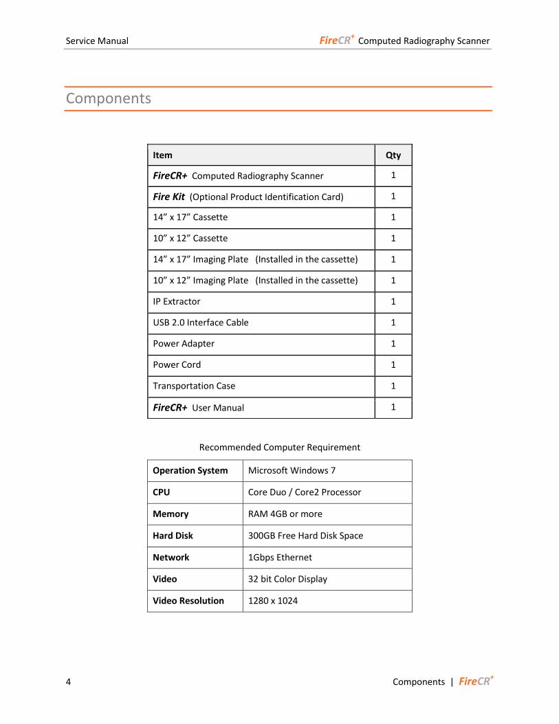
Components
Recommended Computer Requirement
Operation System Microsoft Windows 7
CPU Core Duo / Core2 Processor
Memory RAM 4GB or more
Hard Disk 300GB Free Hard Disk Space
Network 1Gbps Ethernet
Video 32 bit Color Display
Video Resolution 1280 x 1024
Item Qty
FireCR+ Computed Radiography Scanner 1
Fire Kit (Optional Product Identification Card) 1
14” x 17” Cassette 1
10” x 12” Cassette 1
14” x 17” Imaging Plate (Installed in the cassette) 1
10” x 12” Imaging Plate (Installed in the cassette) 1
IP Extractor 1
USB 2.0 Interface Cable 1
Power Adapter 1
Power Cord 1
Transportation Case 1
FireCR+ User Manual 1

Service Manual FireCR+ Computed Radiography Scanner
FireCR+ | Installation 5
Installation
Table Top
1. Install on a flat and stable surface.
2. Adjust the feet underneath the scanner to ensure stability.
3. Allow 50cm (20 inches) of free space at the front for cassette insertion and 20cm (8 inches) in the back for cables and power switch access.
Service Manual FireCR+ Computed Radiography Scanner
6 Installation | FireCR+
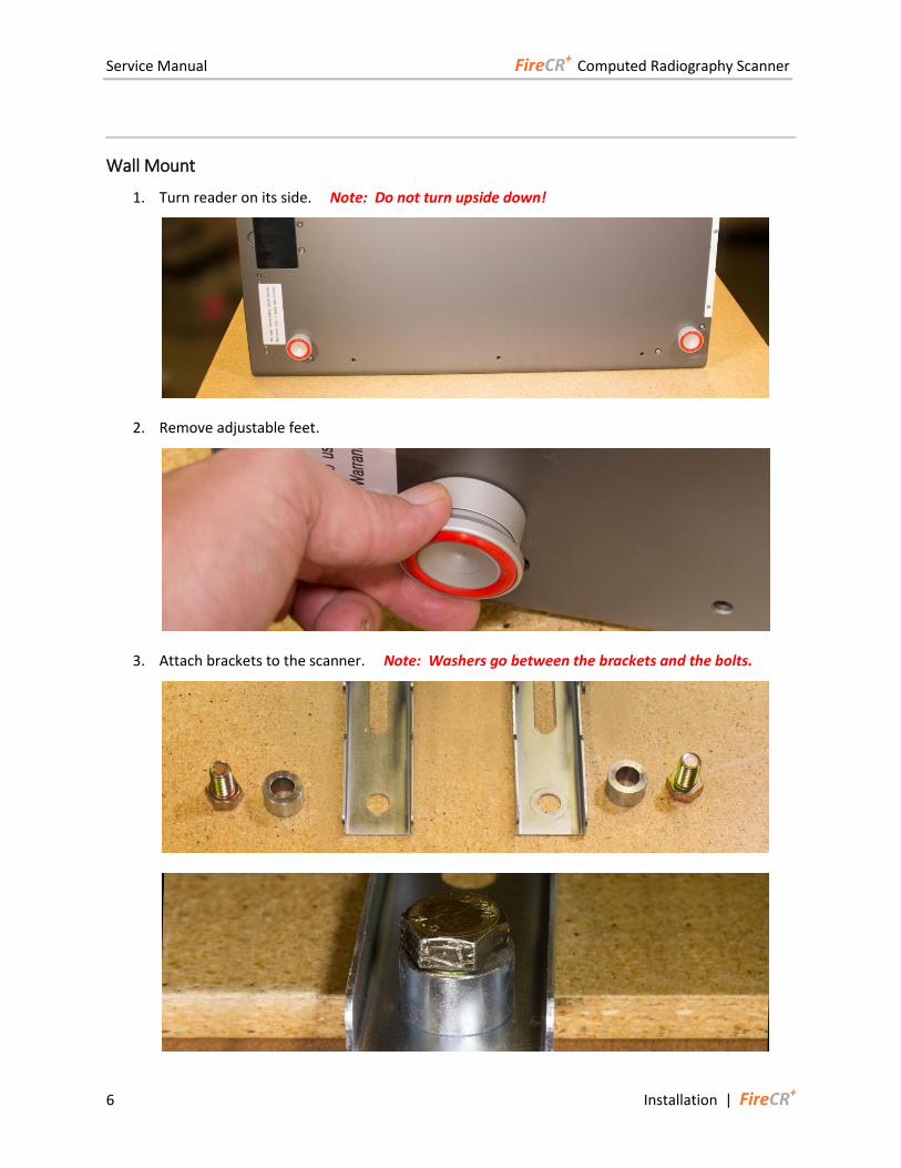
Wall Mount
1. Turn reader on its side. Note: Do not turn upside down!
2. Remove adjustable feet.
3. Attach brackets to the scanner. Note: Washers go between the brackets and the bolts.
Service Manual FireCR+ Computed Radiography Scanner
FireCR+ | Installation 7
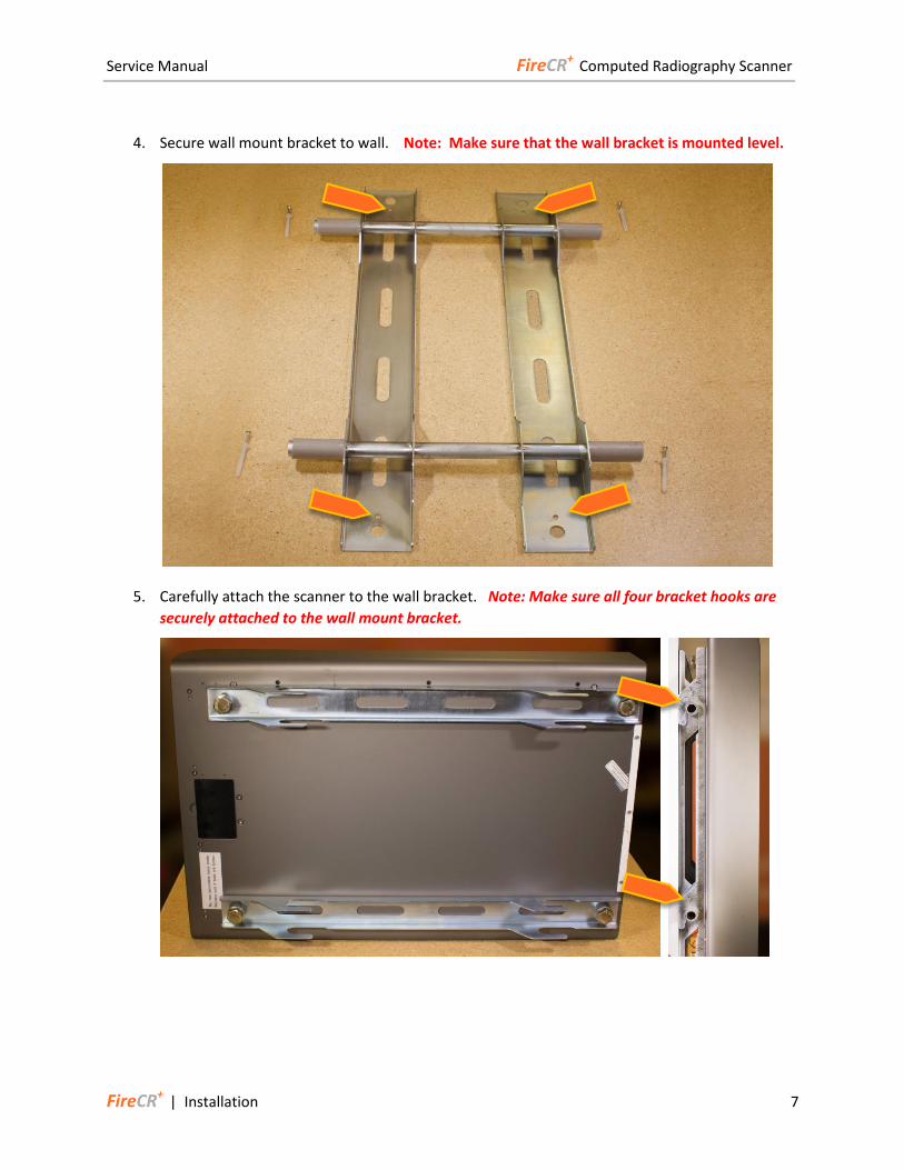
4. Secure wall mount bracket to wall. Note: Make sure that the wall bracket is mounted level.
5. Carefully attach the scanner to the wall bracket. Note: Make sure all four bracket hooks are
securely attached to the wall mount bracket.
Service Manual FireCR+ Computed Radiography Scanner
8 Installation | FireCR+
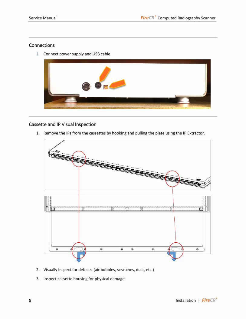
Connections
1. Connect power supply and USB cable.
Cassette and IP Visual Inspection
1. Remove the IPs from the cassettes by hooking and pulling the plate using the IP Extractor.
2. Visually inspect for defects (air bubbles, scratches, dust, etc.)
3. Inspect cassette housing for physical damage.
Service Manual FireCR+ Computed Radiography Scanner
FireCR+ | Calibration 9
Calibration
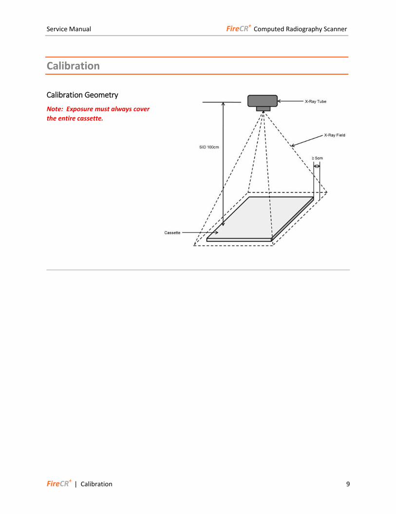
Calibration Geometry
Note: Exposure must always cover
the entire cassette.
Service Manual FireCR+ Computed Radiography Scanner
10 Calibration | FireCR+
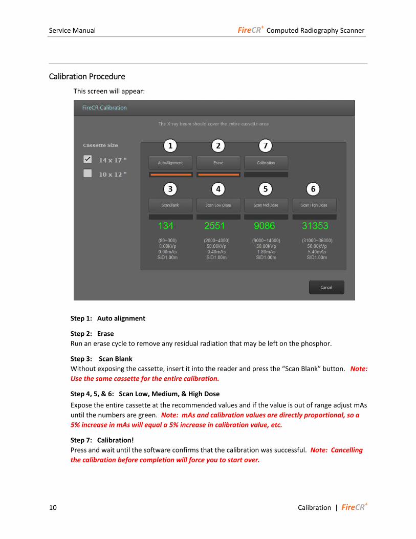
Calibration Procedure
This screen will appear:
Step 1: Auto alignment
Step 2: Erase
Run an erase cycle to remove any residual radiation that may be left on the phosphor.
Step 3: Scan Blank
Without exposing the cassette, insert it into the reader and press the “Scan Blank” button. Note:
Use the same cassette for the entire calibration.
Step 4, 5, & 6: Scan Low, Medium, & High Dose
Expose the entire cassette at the recommended values and if the value is out of range adjust mAs
until the numbers are green. Note: mAs and calibration values are directly proportional, so a
5% increase in mAs will equal a 5% increase in calibration value, etc.
Step 7: Calibration!
Press and wait until the software confirms that the calibration was successful. Note: Cancelling
the calibration before completion will force you to start over.
Service Manual FireCR+ Computed Radiography Scanner
FireCR+ | Calibration 11
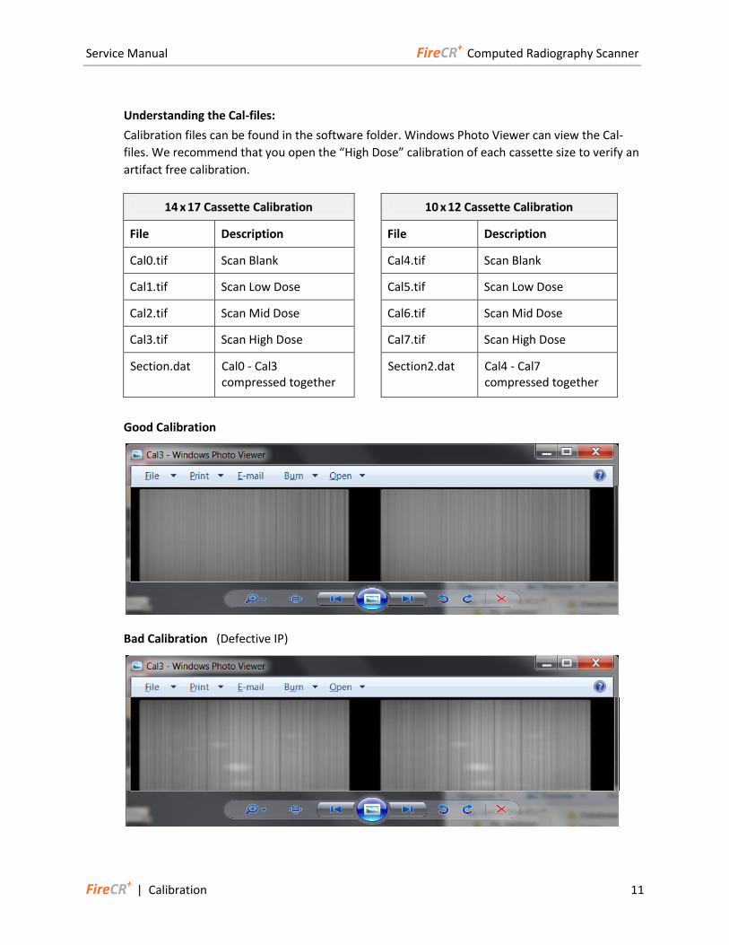
Understanding the Cal-files:
Calibration files can be found in the software folder. Windows Photo Viewer can view the Cal-
files. We recommend that you open the “High Dose” calibration of each cassette size to verify an
artifact free calibration.
14 x 17 Cassette Calibration 10 x 12 Cassette Calibration
File Description File Description
Cal0.tif Scan Blank Cal4.tif Scan Blank
Cal1.tif Scan Low Dose Cal5.tif Scan Low Dose
Cal2.tif Scan Mid Dose Cal6.tif Scan Mid Dose
Cal3.tif Scan High Dose Cal7.tif Scan High Dose
Section.dat Cal0 - Cal3 compressed together
Section2.dat Cal4 - Cal7 compressed together
Good Calibration
Bad Calibration (Defective IP)
Service Manual FireCR+ Computed Radiography Scanner
12 Reader Diagnostics | FireCR+
Reader Diagnostics
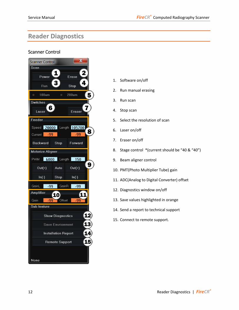
Scanner Control
1. Software on/off
2. Run manual erasing
3. Run scan
4. Stop scan
5. Select the resolution of scan
6. Laser on/off
7. Eraser on/off
8. Stage control *(current should be “40 & “40”)
9. Beam aligner control
10. PMT(Photo Multiplier Tube) gain
11. ADC(Analog to Digital Converter) offset
12. Diagnostics window on/off
13. Save values highlighted in orange
14. Send a report to technical support
15. Connect to remote support.
Service Manual FireCR+ Computed Radiography Scanner
FireCR+ | Reader Diagnostics 13
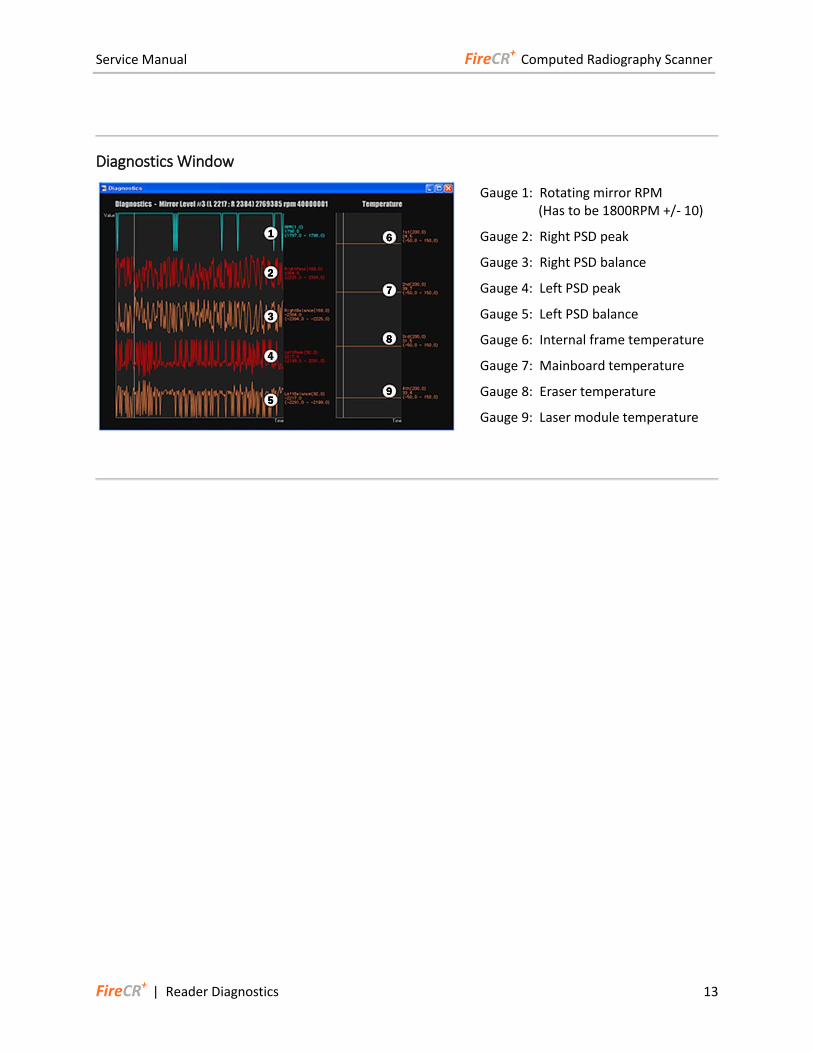
Diagnostics Window
Gauge 1: Rotating mirror RPM (Has to be 1800RPM +/- 10)
Gauge 2: Right PSD peak
Gauge 3: Right PSD balance
Gauge 4: Left PSD peak
Gauge 5: Left PSD balance
Gauge 6: Internal frame temperature
Gauge 7: Mainboard temperature
Gauge 8: Eraser temperature
Gauge 9: Laser module temperature
Service Manual FireCR+ Computed Radiography Scanner
14 Parts Removal/Replacement | FireCR+
Parts Removal/Replacement
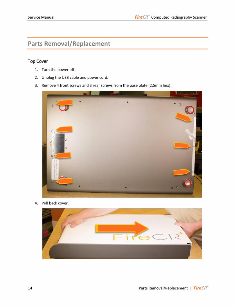
Top Cover
1. Turn the power off.
2. Unplug the USB cable and power cord.
3. Remove 4 front screws and 3 rear screws from the base plate (2.5mm hex).
4. Pull back cover.
Service Manual FireCR+ Computed Radiography Scanner
FireCR+ | Parts Removal/Replacement 15
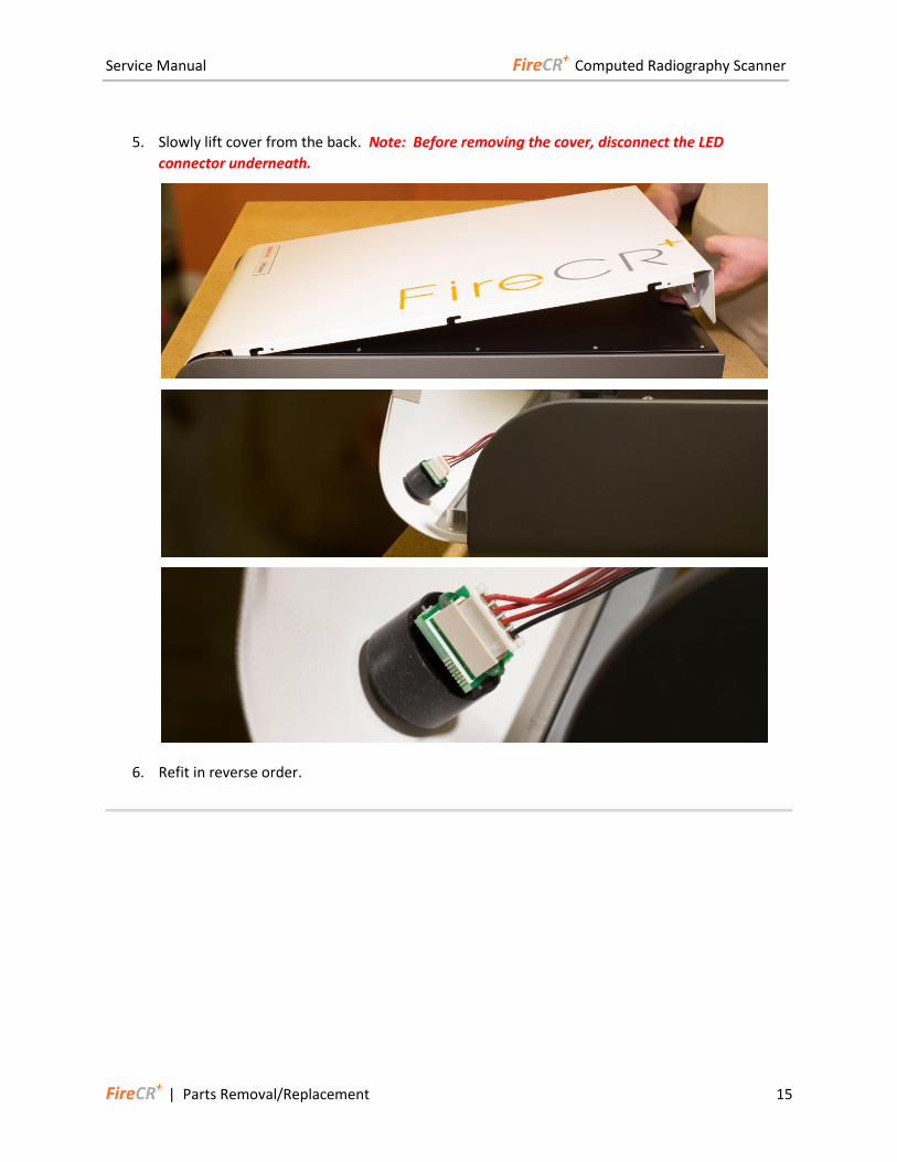
5. Slowly lift cover from the back. Note: Before removing the cover, disconnect the LED
connector underneath.
6. Refit in reverse order.
Service Manual FireCR+ Computed Radiography Scanner
16 Parts Removal/Replacement | FireCR+
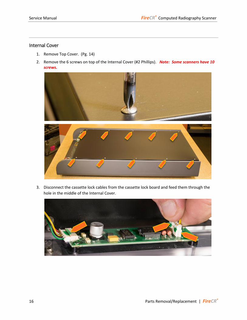
Internal Cover
1. Remove Top Cover. (Pg. 14)
2. Remove the 6 screws on top of the Internal Cover (#2 Phillips). Note: Some scanners have 10 screws.
3. Disconnect the cassette lock cables from the cassette lock board and feed them through the
hole in the middle of the Internal Cover.
Service Manual FireCR+ Computed Radiography Scanner
FireCR+ | Parts Removal/Replacement 17
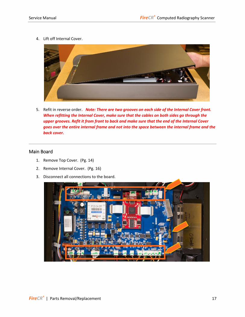
4. Lift off Internal Cover.
5. Refit in reverse order. Note: There are two grooves on each side of the Internal Cover front.
When refitting the Internal Cover, make sure that the cables on both sides go through the
upper grooves. Refit it from front to back and make sure that the end of the Internal Cover
goes over the entire internal frame and not into the space between the internal frame and the
back cover.
Main Board
1. Remove Top Cover. (Pg. 14)
2. Remove Internal Cover. (Pg. 16)
3. Disconnect all connections to the board.
Service Manual FireCR+ Computed Radiography Scanner
18 Parts Removal/Replacement | FireCR+
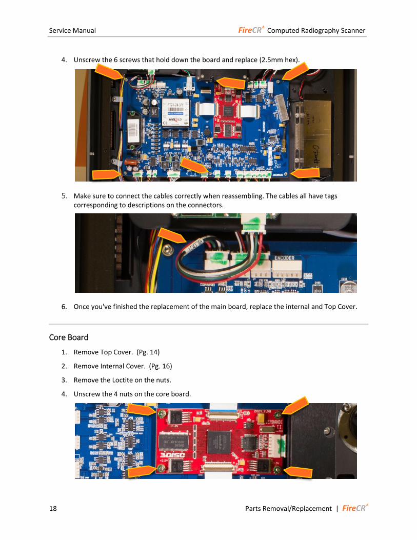
4. Unscrew the 6 screws that hold down the board and replace (2.5mm hex).
5. Make sure to connect the cables correctly when reassembling. The cables all have tags corresponding to descriptions on the connectors.
6. Once you've finished the replacement of the main board, replace the internal and Top Cover.
Core Board
1. Remove Top Cover. (Pg. 14)
2. Remove Internal Cover. (Pg. 16)
3. Remove the Loctite on the nuts.
4. Unscrew the 4 nuts on the core board.
Service Manual FireCR+ Computed Radiography Scanner
FireCR+ | Parts Removal/Replacement 19
5. Disconnect the 2 ribbon cables and wire connector.
6. Replace the old core board with a new core board.
7. Reinstall the nuts to secure the core board.
8. Connect the 2 ribbon cables and wire connector.
9. Put Loctite on the nuts.
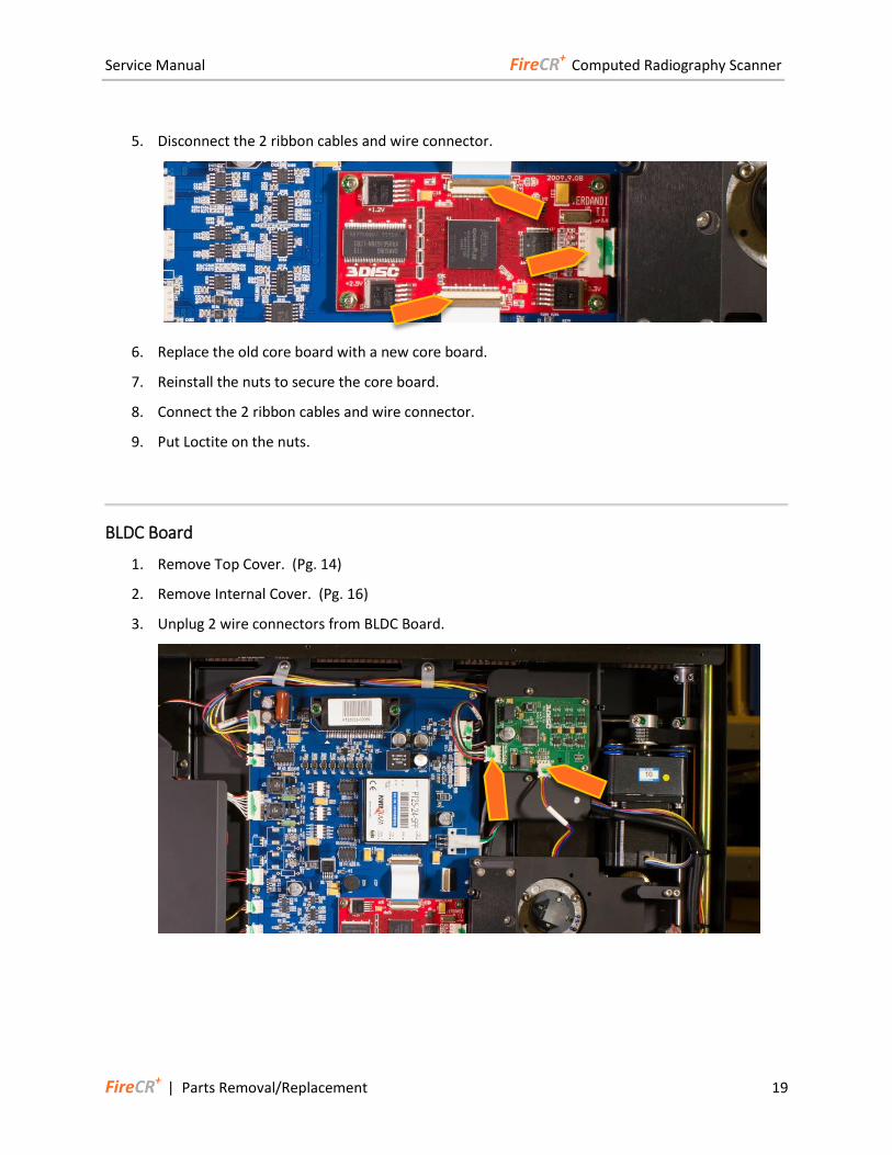
BLDC Board
1. Remove Top Cover. (Pg. 14)
2. Remove Internal Cover. (Pg. 16)
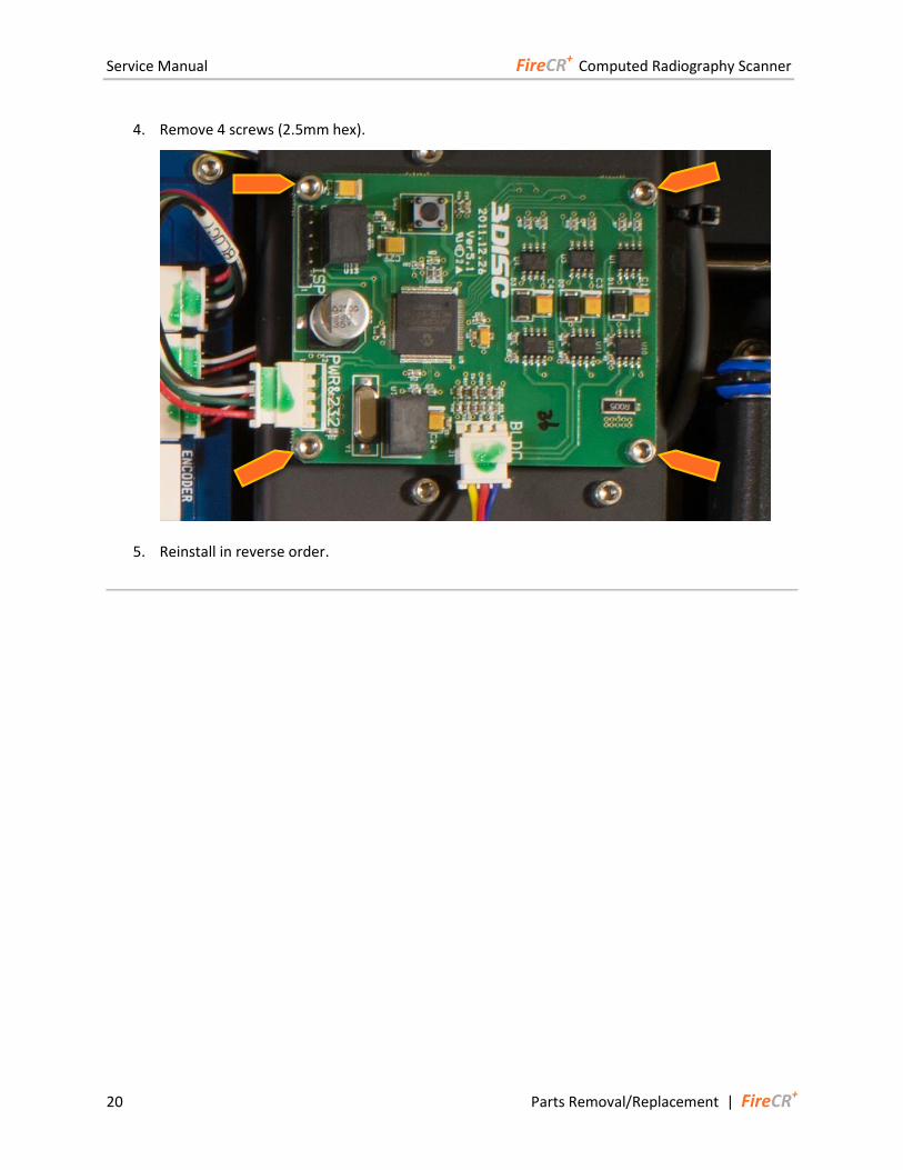
3. Unplug 2 wire connectors from BLDC Board.
Service Manual FireCR+ Computed Radiography Scanner
20 Parts Removal/Replacement | FireCR+
4. Remove 4 screws (2.5mm hex).
5. Reinstall in reverse order.
Service Manual FireCR+ Computed Radiography Scanner
FireCR+ | Parts Removal/Replacement 21
Cassette Lock Motor Board
1. Remove Top Cover. (Pg. 14)
2. Remove Internal Cover. (Pg. 16)
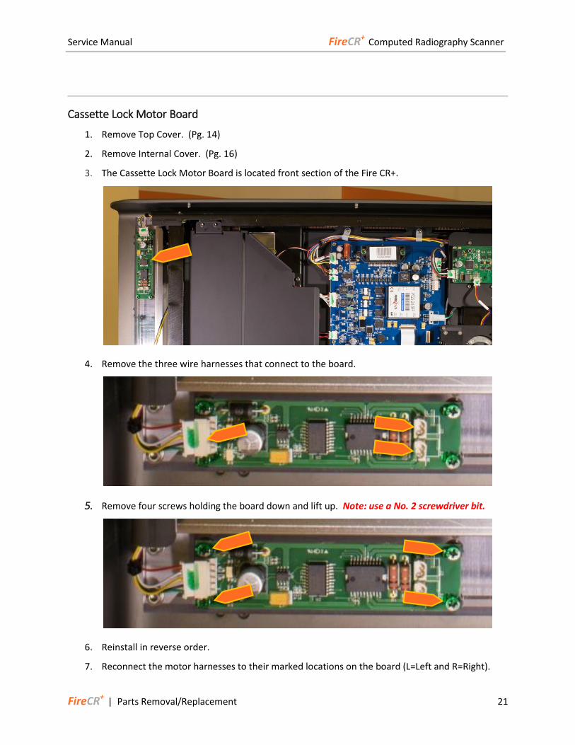
3. The Cassette Lock Motor Board is located front section of the Fire CR+.
4. Remove the three wire harnesses that connect to the board.
5. Remove four screws holding the board down and lift up. Note: use a No. 2 screwdriver bit.
6. Reinstall in reverse order.
7. Reconnect the motor harnesses to their marked locations on the board (L=Left and R=Right).
Service Manual FireCR+ Computed Radiography Scanner
22 Parts Removal/Replacement | FireCR+
Optic Plate
1. Remove Top Cover. (Pg. 14)
2. Remove Internal Cover. (Pg. 16)
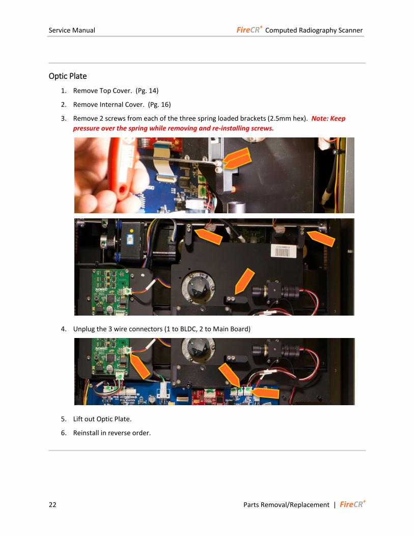
3. Remove 2 screws from each of the three spring loaded brackets (2.5mm hex). Note: Keep
pressure over the spring while removing and re-installing screws.
4. Unplug the 3 wire connectors (1 to BLDC, 2 to Main Board)
5. Lift out Optic Plate.
6. Reinstall in reverse order.
Service Manual FireCR+ Computed Radiography Scanner
FireCR+ | Parts Removal/Replacement 23
Aligner Motor
1. Remove Top Cover. (Pg. 14)
2. Remove Internal Cover. (Pg. 16)
3. Remove Optic Plate. (Pg. 22)
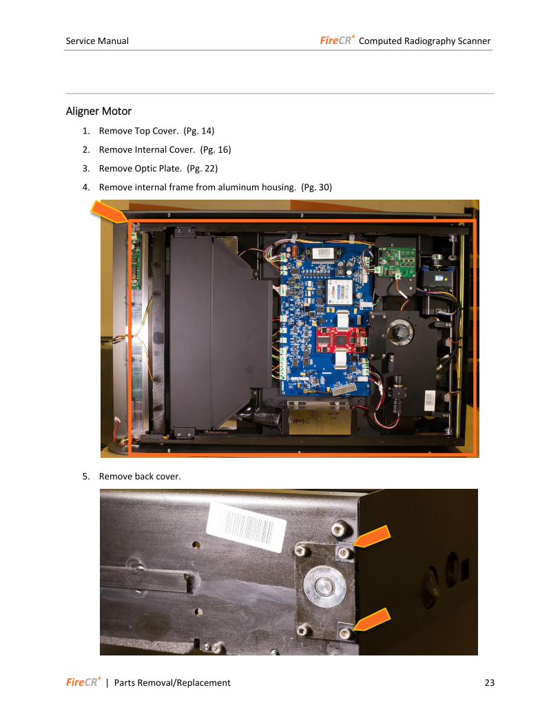
4. Remove internal frame from aluminum housing. (Pg. 30)
5. Remove back cover.
Service Manual FireCR+ Computed Radiography Scanner
24 Parts Removal/Replacement | FireCR+
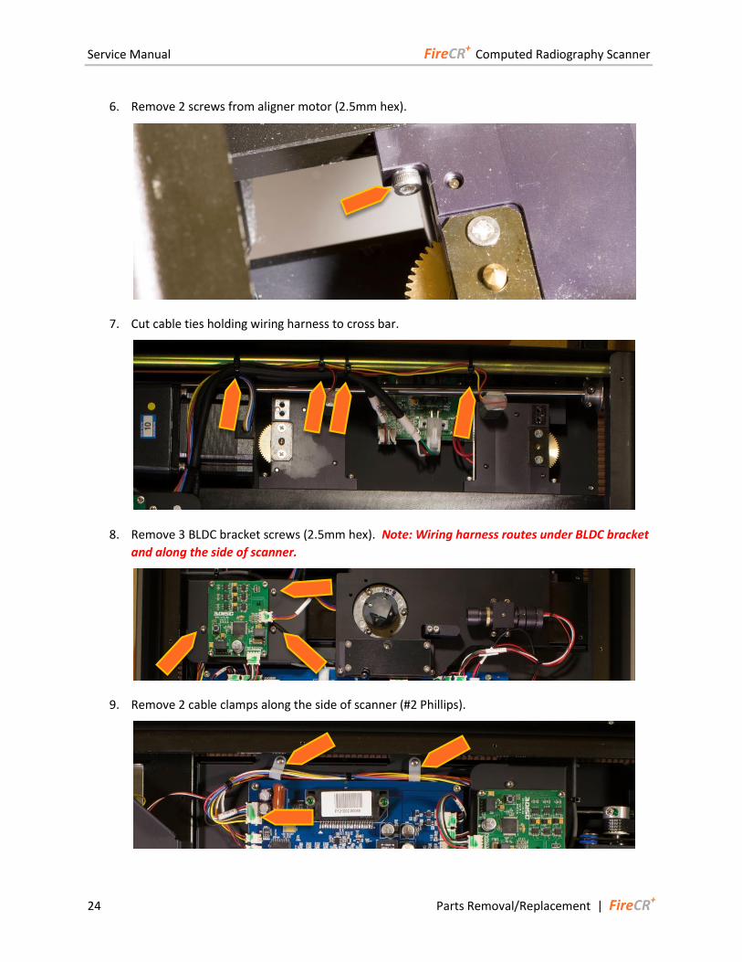
6. Remove 2 screws from aligner motor (2.5mm hex).
7. Cut cable ties holding wiring harness to cross bar.
8. Remove 3 BLDC bracket screws (2.5mm hex). Note: Wiring harness routes under BLDC bracket
and along the side of scanner.
9. Remove 2 cable clamps along the side of scanner (#2 Phillips).
Service Manual FireCR+ Computed Radiography Scanner
FireCR+ | Parts Removal/Replacement 25
10. Unplug wire connector from Main Board.
11. Process is the same for other aligner motor.
12. Reinstall in reverse order.
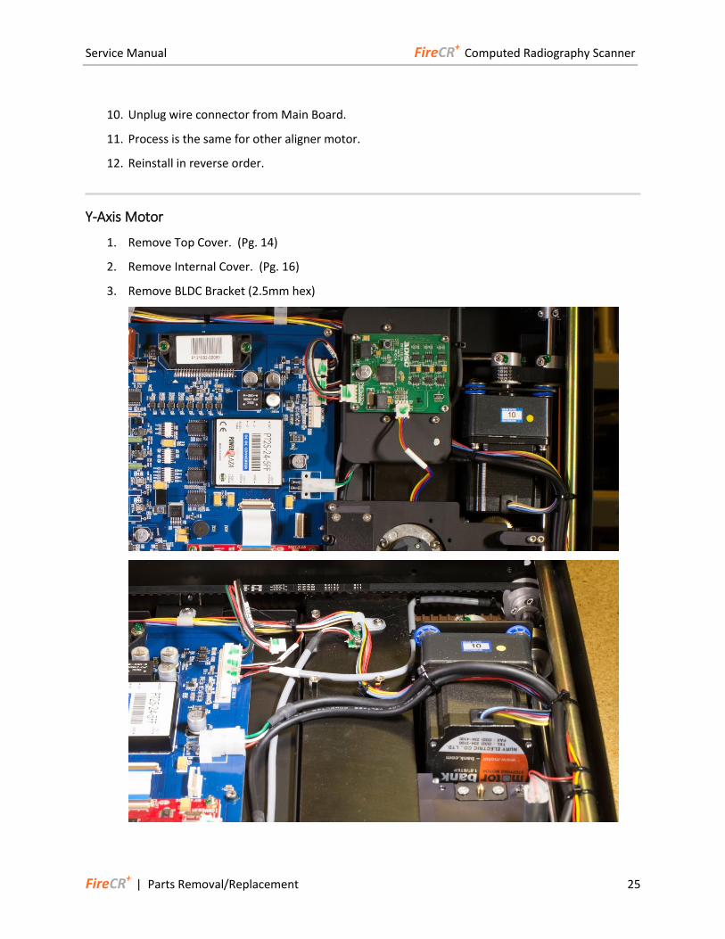
Y-Axis Motor
1. Remove Top Cover. (Pg. 14)
2. Remove Internal Cover. (Pg. 16)
3. Remove BLDC Bracket (2.5mm hex)
Service Manual FireCR+ Computed Radiography Scanner
26 Parts Removal/Replacement | FireCR+
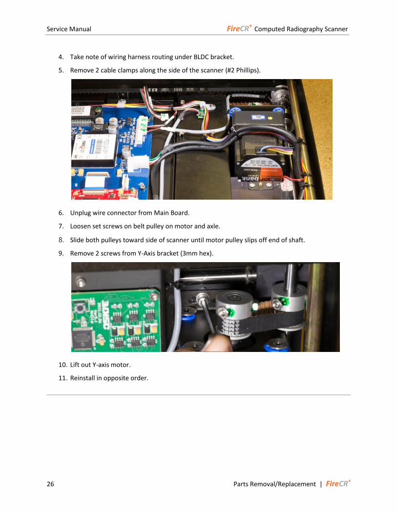
4. Take note of wiring harness routing under BLDC bracket.
5. Remove 2 cable clamps along the side of the scanner (#2 Phillips).
6. Unplug wire connector from Main Board.
7. Loosen set screws on belt pulley on motor and axle.
8. Slide both pulleys toward side of scanner until motor pulley slips off end of shaft.
9. Remove 2 screws from Y-Axis bracket (3mm hex).
10. Lift out Y-axis motor.
11. Reinstall in opposite order.
Service Manual FireCR+ Computed Radiography Scanner
FireCR+ | Parts Removal/Replacement 27
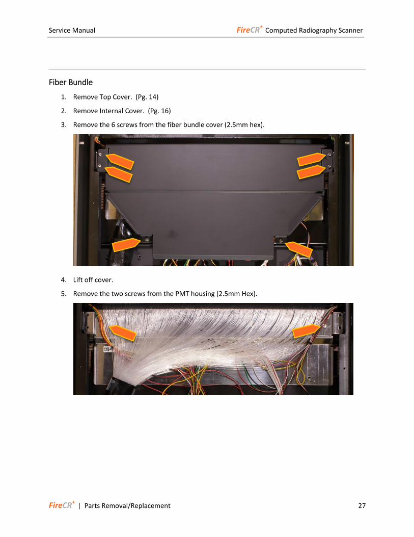
Fiber Bundle
1. Remove Top Cover. (Pg. 14)
2. Remove Internal Cover. (Pg. 16)
3. Remove the 6 screws from the fiber bundle cover (2.5mm hex).
4. Lift off cover.
5. Remove the two screws from the PMT housing (2.5mm Hex).
Service Manual FireCR+ Computed Radiography Scanner
28 Parts Removal/Replacement | FireCR+
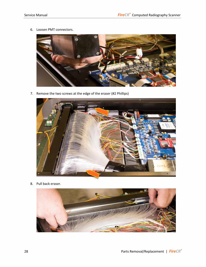
6. Loosen PMT connectors.
7. Remove the two screws at the edge of the eraser (#2 Phillips)
8. Pull back eraser.
Service Manual FireCR+ Computed Radiography Scanner
FireCR+ | Parts Removal/Replacement 29
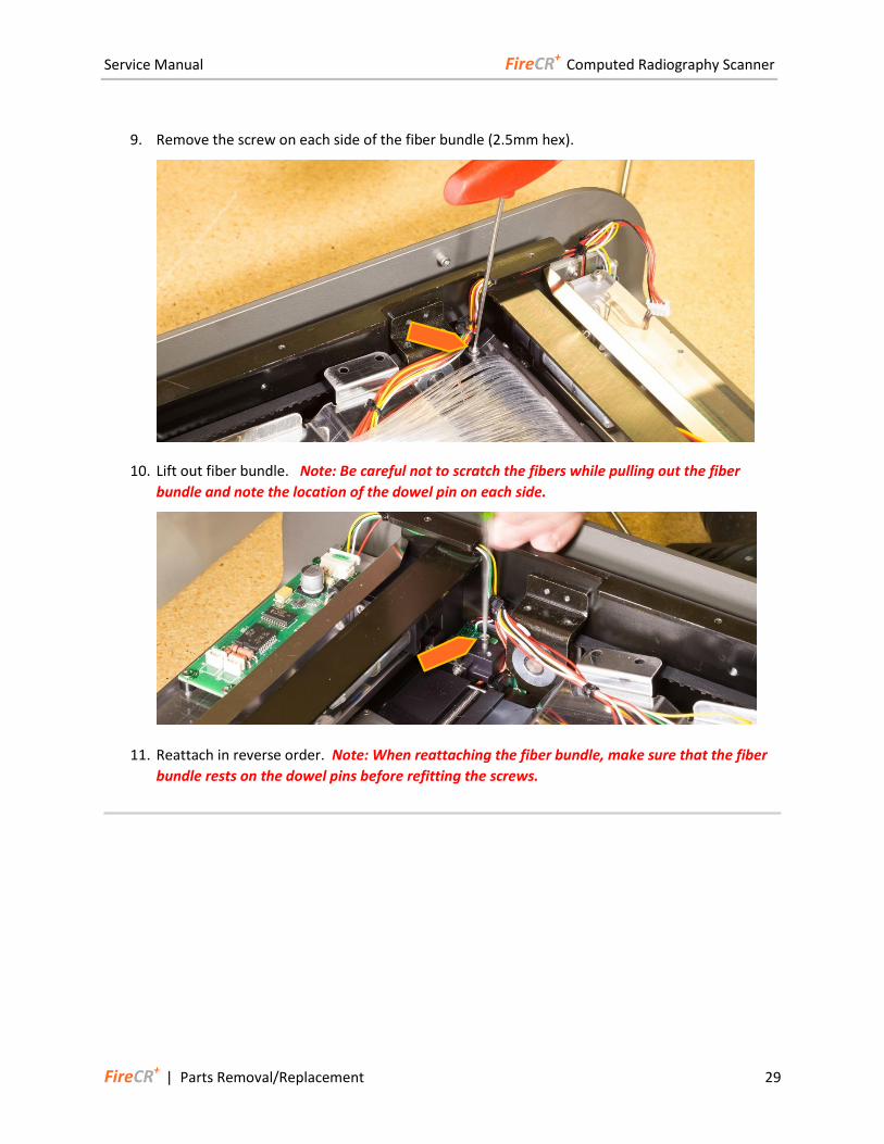
9. Remove the screw on each side of the fiber bundle (2.5mm hex).
10. Lift out fiber bundle. Note: Be careful not to scratch the fibers while pulling out the fiber
bundle and note the location of the dowel pin on each side.
11. Reattach in reverse order. Note: When reattaching the fiber bundle, make sure that the fiber
bundle rests on the dowel pins before refitting the screws.
Service Manual FireCR+ Computed Radiography Scanner
30 Parts Removal/Replacement | FireCR+
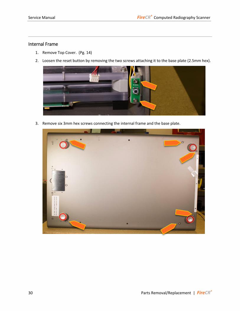
Internal Frame
1. Remove Top Cover. (Pg. 14)
2. Loosen the reset button by removing the two screws attaching it to the base plate (2.5mm hex).
3. Remove six 3mm hex screws connecting the internal frame and the base plate.

Service Manual FireCR+ Computed Radiography Scanner
FireCR+ | Parts Removal/Replacement 31
4. Set the reader back down and remove from the bottom the two screws by the speed plate.
5. Remove the internal frame by lifting on the edge of each side. Note: Do not lift on anything but
the Internal Cover as pulling on components will damage them!
6. When reattaching the internal frame, note that there are two pins at the bottom of the internal
frame that fit into the base plate. Make sure that these pins fit before refitting the screws to the
bottom of the base plate.
Service Manual FireCR+ Computed Radiography Scanner
32 Parts Removal/Replacement | FireCR+
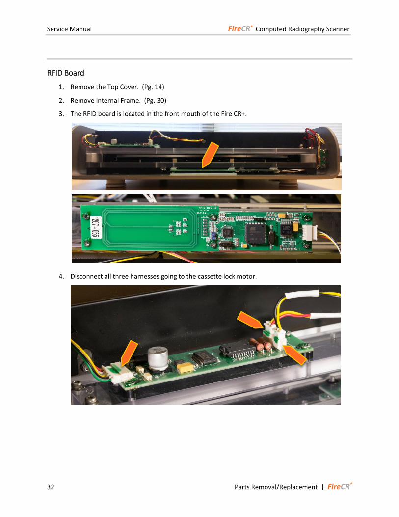
RFID Board
1. Remove the Top Cover. (Pg. 14)
2. Remove Internal Frame. (Pg. 30)
3. The RFID board is located in the front mouth of the Fire CR+.
4. Disconnect all three harnesses going to the cassette lock motor.
Service Manual FireCR+ Computed Radiography Scanner
FireCR+ | Parts Removal/Replacement 33
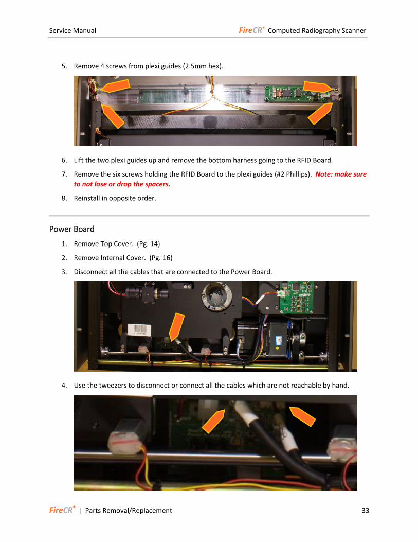
5. Remove 4 screws from plexi guides (2.5mm hex).
6. Lift the two plexi guides up and remove the bottom harness going to the RFID Board.
7. Remove the six screws holding the RFID Board to the plexi guides (#2 Phillips). Note: make sure
to not lose or drop the spacers.
8. Reinstall in opposite order.
Power Board
1. Remove Top Cover. (Pg. 14)
2. Remove Internal Cover. (Pg. 16)
3. Disconnect all the cables that are connected to the Power Board.
4. Use the tweezers to disconnect or connect all the cables which are not reachable by hand.
Service Manual FireCR+ Computed Radiography Scanner
34 Parts Removal/Replacement | FireCR+
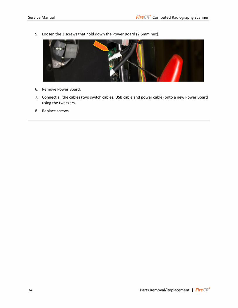
5. Loosen the 3 screws that hold down the Power Board (2.5mm hex).
6. Remove Power Board.
7. Connect all the cables (two switch cables, USB cable and power cable) onto a new Power Board
using the tweezers.
8. Replace screws.
Service Manual FireCR+ Computed Radiography Scanner
FireCR+ | Troubleshooting 35
Troubleshooting
Image Quality
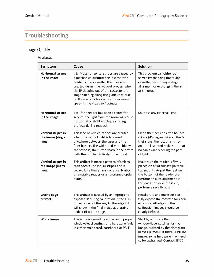
Artifacts
Symptom Cause Solution
Horizontal stripes in the image
#1: Most horizontal stripes are caused by a mechanical disturbance in either the reader or the cassette. The lines are created during the readout process when the IP skipping out of the cassette, the stage skipping along the guide rods or a faulty Y-axis motor causes the movement speed in the Y-axis to fluctuate.
This problem can either be solved by changing the faulty cassette, performing a stage alignment or exchanging the Y-axis motor.
Horizontal stripes in the image
#2: If the reader has been opened for service, the light from the room will cause horizontal or slightly oblique striping artifacts during readout.
Shut out any external light.
Vertical stripes in the image (single lines)
This kind of vertical stripes are created when the path of light is hindered anywhere between the laser and the fiber bundle. The wider and more blurry the stripe is, the further back in the optics path the problem is likely to be found.
Clean the fiber ends, the bounce mirror (45 degree mirror), the F-theta lens, the rotating mirror and the laser and make sure that no cables are blocking the path of light.
Vertical stripes in the image (many lines)
This artifact is more a pattern of stripes than several individual stripes and is caused by either an improper calibration, an unstable reader or an unaligned optics plate.
Make sure the reader is firmly placed on a flat surface (in table top mount). Adjust the feet on the bottom of the reader then perform an auto alignment. If this does not solve the issue, perform a recalibration.
Grainy edge artifact
This artifact is caused by an improperly exposed IP during calibration. If the IP is not exposed all the way to the edges, it will show in the final image as a grainy and/or distorted edge.
Recalibrate and make sure to fully expose the cassette for each exposure. All edges in the calibration images should be clearly defined.
White image This issue is caused by either an improper window/level settings or a hardware fault in either mainboard, coreboard or PMT.
Start by adjusting the window/level settings for the image, assisted by the histogram in the QA menu. If there is still no image, some hardware may need to be exchanged. Contact 3DISC.
Service Manual FireCR+ Computed Radiography Scanner
36 Troubleshooting | FireCR+
Artifacts (cont.)
Symptom Cause Solution
Image is extremely dark
This issue is usually caused by an excessive overexposure of the IP or improper window/level settings for the image
Start by adjusting the window/level settings for the image, assisted by the histogram in the QA menu. If large parts of the image have been burnt away, the image has most likely been overexposed. An overexposure can be determined by an exposure index at 2500 or higher.
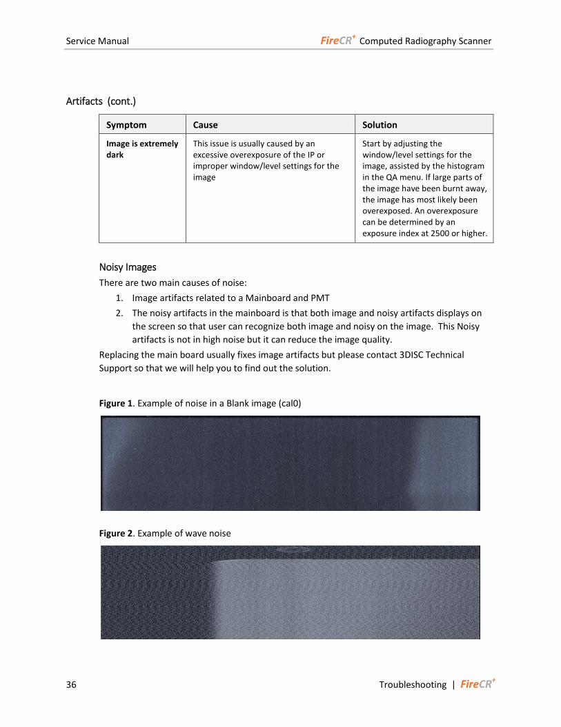
Noisy Images
There are two main causes of noise:
1. Image artifacts related to a Mainboard and PMT
2. The noisy artifacts in the mainboard is that both image and noisy artifacts displays on
the screen so that user can recognize both image and noisy on the image. This Noisy
artifacts is not in high noise but it can reduce the image quality.
Replacing the main board usually fixes image artifacts but please contact 3DISC Technical
Support so that we will help you to find out the solution.
Figure 1. Example of noise in a Blank image (cal0)
Figure 2. Example of wave noise
Service Manual FireCR+ Computed Radiography Scanner
FireCR+ | Troubleshooting 37
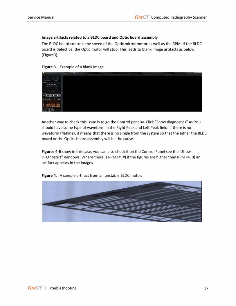
Image artifacts related to a BLDC board and Optic board assembly
The BLDC board controls the speed of the Optic mirror motor as well as the RPM. If the BLDC
board is defective, the Optic motor will stop. This leads to blank image artifacts as below
(Figure3).
Figure 3. Example of a blank image.
Another way to check this issue is to go the Control panel=> Click “Show diagnostics” => You
should have some type of waveform in the Right Peak and Left Peak field. If there is no
waveform (flatline), it means that there is no single from the system so that the either the BLDC
board or the Optics board assembly will be the cause.
Figures 4-6 show in this case, you can also check it on the Control Panel see the “Show
Diagnostics” windows. Where there is RPM (#, #) if the figures are higher than RPM (4, 0) an
artifact appears in the images.
Figure 4. A sample artifact from an unstable BLDC motor.
Service Manual FireCR+ Computed Radiography Scanner
38 Troubleshooting | FireCR+
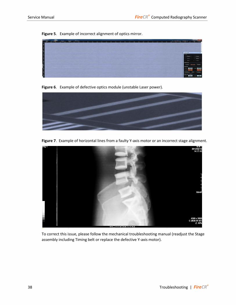
Figure 5. Example of incorrect alignment of optics mirror.
Figure 6. Example of defective optics module (unstable Laser power).
Figure 7. Example of horizontal lines from a faulty Y-axis motor or an incorrect stage alignment.
To correct this issue, please follow the mechanical troubleshooting manual (readjust the Stage
assembly including Timing belt or replace the defective Y-axis motor).
Service Manual FireCR+ Computed Radiography Scanner
FireCR+ | Troubleshooting 39
Mechanical Noise
Belt Jumping
Bent main board plate
1. Remove Top Cover. (Pg. 14)
2. Remove internal frame from base.
3. Remove two spike fastener clips holding the main board plate.
4. Remove 4 hex screws.
5. Once screws and clips are removed from the main board plate begin to
push up towards the board until the plate is straight again.
6. Reinstall in reverse order.
Belt tension
1. Remove Top Cover. (Pg. 14)
2. Remove the Internal Cover (Pg. 16) and locate the Y-axis motor.
3. Loosen the two Allen screws on the Y-axis motor’s base.
4. Pry the Y-axis motor forward keeping it straight until the tension on the
belt is fairly tight.
5. Tighten the screws.
6. Reinstall in reverse order.
Unaligned stage
1. Remove Top Cover. (Pg. 14)
2. Remove the Internal Cover. (Pg. 16)
3. Loosen the two Allen head screws on each side of the main axle pulley.
4. Move the stage assembly around.
5. Slide the stage assembly all the way to the back of the scanner.
6. Tighten the Allen screws on each pulley.
7. Reinstall in reverse order.
Broken cassette lock
1. Replace cassette.

Service Manual FireCR+ Computed Radiography Scanner
40 Troubleshooting | FireCR+