Firearm Manuals
46
SELI 10/22 By Wayne Thornbrugh _ M _ i I _ _ _ _ .. he TEK Full Auto Conversion 229
Transcript of Firearm Manuals

SELI 10/22
By Wayne Thornbrugh
_
M
_
■ ♦
i
I
_
_ _ _ ..
he TEK Full Auto Conversion
229

7 iw ?
10/22 By Wayne Thornbrugh
The TEK Full Auto Conversion
Desert Publications El Dorado, AR 71731-1751
I
Select Fire 10/22
By Wayne Thombrugh
©1985 by Desert Publications P.O. Box 1751
El Dorado, AR 71731 501-862-2077
ISBN #:0-87947-229-4
109876543
Desert Publication is a division of The DELTA GROUP, Ltd.
Direct all inquires & orders to the above address.
All rights reserved. Except of use in a review, no portion of this book may be reproduced by any means known or unknown without the expressed written permission of the publisher.
Neither the author nor the publisher assumes any responsibility for the use or misuse of the information contained in this book.
it

Table Of Contents
Foreword . 1
Which Configuration Is Best, The Front
Mounted Bolt Arrestor Or The Rear? . 3
Fitting The Auto-Sear Trip Tolerance . 5
Full Auto Operation—Rear Mounted Arrestor . 17
Fitting Rear Arrestor To Bolt Clearance. 23
Fitting Front Mounted Arrestor To Bolt Clearance. 33
111
WARNING
Since the Hughes’ Amendment, which went into effect on May 19,1986, it is no longer possible for civilians to do Form 1 conversions or manufacturing of machine guns. Also, Class II manufacturers can no longer produce machine guns for civilian consumption.
This book is produced and sold for academic purposes only. Since the original text of this book was written before the above date, some of the text may be interpreted otherwise.
Let this warning emphasize that the actual production of a machine gun by a civilian would be in violation of Federal Law!

FOREWORD
The designs offered herein are not the brain¬ child of a great gun designer but the stubborn persistence of a retired military ordnance man who undertook the project simply because they said it couldn’t be done. The project developed into a small Class II manufacturing business which sold the converted 10/22’s in most of the states where they are legal to own. To date, after at least 100 thousand rounds fired, we have yet to have a parts failure, Ruger’s or our own.
After the final development of the first three prototypes, we started a record of rounds fired, which gun and what ammunition. After thirty thousand rounds we quit keeping records because all major brands seemed to work equally well except for residue, grease and wax. C.C.l. ammunition seems to burn cleaner and leave less residue than all the others. So, for that reason we must recommend their product.
Hardly a day goes by that we do not receive a letter or phone call from someone who wants to roll their own. In our supply/demand economy someone will usually step forward to fill a void sensed by the public. 1 believe this book will fill that void, otherwise, neither the publisher nor I would have undertaken the task. We both hope you concur.
It is not difficult to design a drop-in automatic sear, to trip it and bypass the trigger sear to allow the 10/22 to, theoretically, cycle auto¬ matically. Many hobbyists, gunsmiths and Class II manufacturers have attempted to convert the Ruger 10/22 to closed bolt, select fire since 1964, when Bill Ruger placed it on the market. None, to my knowledge, have worked with any degree of reliability. Most have not and will not work, period!
The first step towards solving any problem is recognizing the fact that there is one and what it is! The answer to converting the 10/ 22 to select fire is solving the problem of bolt bounce. In counter-recoil the 10/22 bolt will bounce upwards of 3/16” after striking the breech face of the barrel. This allows the hammer to expend its energy on the bolt rather than the firing pin.
With the bolt just .025 out of battery, the bolt will block the hammer from the firing pin due to the angle of attack. This is, in reality, a safety feature as well as a method to prevent easy conversion of the gun to slam fire. Bill Ruger knew exactly what he was doing when he designed the 10/22.
Plans, and in some cases parts, have been available to convert the 10/22 to closed bolt,

SELECT FIRE 10/22
select fire, but by and large they have over¬ looked the problem of bolt bounce or con¬ veniently ignored it for the sake of commerce.
Others have given up on a closed bolt system and designed elaborate open bolt systems.
An open bolt system for the .22 rimfire
cartridge in any configuration is unsatisfactory simply because the cartridge case does not lend itself for an open bolt mode. In the open bolt mode the firing pin must precede the bolt, be it
fixed or pivoted. This allows the firing pin to make contact with the rim of the case which holds the priming mixture before the bolt is
fully closed and any way you cut it, this amounts to headspace—excessive headspace.
This is why you get all those ruptured cases and a face full of burnt powder and gas if you are a
lelt-handed shooter. Needless to say, repeated stoppages are in order. The action is quickly
contaminated with powder residue due to its being blown out the wrong way!
Firearms in .22 rimfire caliber have, for over 100 years, suffered from the toy or plinker
stigma. The average shooter will accept mediocre
ammunition, cheap and unreliable accessories but, above all, the poor guy will lay out more money than he did for the gun for a couple of
high capacity magazines only to have few work properly! Does he complain to the manufacturer
or request a replacement or refund? No, he
simply clears the stoppage and accepts it as the nature of the beast. It doesn't have to be that
way! This same shooter would in no way accept
this performance in his hunting rifle nor would
a law enforcement officer accept this perform¬ ance from his service arm.
There is a 50 round magazine available that, with some modifications and testing, can be
made 98 to 99% reliable and that’s pretty good odds. A self-addressed stamped envelope to the
author will bring you up to date on the care and feeding of aftermarket magazines.
Wayne Thornbrugh 14615 Hwy. 12 Orofino, ID 83544
2

Which Configuration Is Best, The Front Mounted Bolt Arrestor Or The Rear?
We believe there is a place for both and that you must make the choice based upon your needs and your capabilities. The rear mounted
arrestor is easier for those with limited tools. We developed the rear mounted system with the
do-it-yourself builder in mind because there is a milling operation involved on the bolt in the front mounted system. Although the operation
is simple, you still must have a milling machine or access to one.
We have fired over 10 thousand rounds through our rear mounted arrestor prototype
with no stoppages (magazine failures excluded). You should be aware, however, that the arrestor is actuated, both lifted and lowered, by spring
pressure. Conceivably, if the mechanism became contaminated enough w'ith grease, wax. dirt
and powder residue, the spring action which lowers the arrestor might not be great enough to
overcome the added friction. In our testing this did not happen. However,
we disassembled the gun for cleaning and
inspecting every few hundred rounds. Antici¬ pating that the lowering of the arrestor could
possibly be a problem with an extremely dirty gun, we ran a test of 100 rounds fired with a
locked arrestor, allowing the full blow' back
force of the bolt to be taken by the arrestor lug.
Nothing came apart, no damage was done except a very slight marking of the bolt and a very small upsetting of the arrestor lug surface.
In the front mounted bolt arrestor svstem the
arrestor is cammed down by the positive action
of the hammer mounted cam-down pin. The
arrestor is free to fail on its own weight since all spring pressure is removed before the hammer
reaches the firing pin, but there is not enough time for this to happen since its speed of fall is slower than the movement of the bolt. Hence,
the cam-down pin on the hammer for fast,
positive action.
If you have read this far and you think you want to tackle the job, consider this: it cannot
be done and made to work with any degree of
reliability if you do not have access to a good drill press. You must, also, have access to an
oven or torch for annealing and heat treating.
This can be done with a throwaway propane torch if you have a good tip assortment. You will need a quality dial indicating caliper to lay
out the hole locations in the trigger housing and various parts. If you have a heavy duty drill press, it can be equipped with an X & Y feeding
milling table and used for any required milling
operation.

SELECT FIRE 10/22
GENERAL NOTES: Please read before beginning conversion.
1. Please wear adequate eye protection during all operations, both machining and shooting.
2. There are 4 different variations which can be used depending on your personal choice: The bolt arrestor can be either front mounting type or a rear mounting type. The modification to the trigger can be done 2 ways. The simplest way requires your trigger finger to exert some upward force at the time the trigger is pulled. This causes full auto firing. A normal, straight back pull fires semi-auto. A more sophisticated modification features a select lever that allows you a positive selection between full and semi-auto.
3. You may substitute 3-48 socket head screws for the 3-56. Obtain them all .250 long. You will need one that length—the rest can be cut shorter.
4. Unless you are experienced at heat treating and have a furnace you are probably better off to make the necessary parts from flat ground mild steel and case harden.
5. You will need an extra .125 dia x .960 long dowel pin for the auto-sear. Use the Ruger ejector pin for the auto-sear and use the new pin for the ejector.
6. There is a small lip on most of Rugers trigger housings where the trigger comes thru into the trigger guard. Remove enough of this to allow free movement of the select lever if you are building the Model II mechanism.
7. There is no alteration to the ejector when using the front mounted arrestor. The long arm of the auto-sear spring is set behind the ejector pin. A small rod with a notch filed in the end makes this easy. The hammer mounted arrestor lifting spring arm goes to the right of the long arm of the auto-sear spring. In other words, from left to right; arrestor— ejector—long arm of auto-sear spring—arrestor lifting spring arm.
8. The sear surface of the auto-sear must be fitted to the auto-sear notch of the hammer with enough height to allow the trigger sear to move under the original trigger sear cut in the hammer. There
should not be excessive clearance, otherwise the hammer will fall too violently down onto the trigger sear and over a period of time could cause damage to the sear surfaces. Just enough clearance to allow the trigger sear to move easily under the hammer notch with no binding is what we’re after. One good way to determine this clearance is when the auto¬ sear is pushed off by hand the top of the hammer will move about 1/8” forward when dropping to trigger sear engagement.
9. When using the front mounted arrestor, a .187 dia x .950 long slave pin must be used when assembling the trigger housing to the receiver. Assemble the trigger housing and all parts in place using the slave pin to position the arrestor. Retract the bolt 1/4 inch or soand placean empty .22 rimfire case or equal space between the bolt face and barrel. Place trigger housing in receiver and insert rear receiver cross pin first. Insert front cross pin, pushing out and replacing the slave pin. Do this with action upside down and insert cross pins from near and push thru, going away from you. This will prevent binding. Caution: these are push fits, not drive fits!
10. Where screws must be locked after fitting final assembly, they can be either Loc-Tite or a binding, female thread can be cut as lollows: Using a starting tap (longer taper) only partially tap, leaving a couple of threads undersize so as to bind on the screw threads. You might wish to practice this on a scrap of metal before tapping the actual part.
11. When you are ready to test fire, first do it on the workbench. WEAR EYE PROTECTION! Remove bullet and powder from a few rounds and insert one in the chamber. With the barrel in a padded vise and the action upside down, it is easy to fully retract the bolt, select semi orfull auto with the other hand and let the bolt slam closed. Run several rounds thru and inspect the firing pin indentations. The indentations should show no discernible difference between semi and full auto.
12. Unless otherwise noted, all dimensions are in inches.
4

Fitting The Auto-Sear Trip Tolerance
Disassemble the hammer strut and spring. Wind a spring from .029 spring wire to
temporarily replace the regular hammer spring and reassemble. If you use the regular hammer spring while adjusting the auto-sear it will
damage the sear surface since it has not been hardened yet.
Assemble the bolt, cocking handle and recoil
spring into the receiver. Secure the barrel in a padded vise, action upside down. Assemble the
hammer assembly and auto-sear with spring into the trigger housing. The long arm of the
A lull auto sear is shown here. Note that the tang has a slight bend. A slight bend is necessary during final fitting. This adjusts the auto-sear to trip at just the right time.
auto-sear spring is set behind the ejector pin. Retract the bolt slightly and place an empty .22 case or something similar between the bolt face
and the face of the barrel in order to insure that the position of the auto-sear trip pin is behind
the auto-sear tail.
Place the trigger housing in the receiver and secure with the 2 receiver cross pins. Insert the
bolt stop pin into the receiver. Remove the
empty .22 case holding the bolt partly open and place a .020 feeler gauge between the bolt face
and the barrel face opposite the extractor side of the bolt but not deep enough to allow the
firing pin to strike the feeler gauge, otherwise the firing pin will be damaged.
Holding the feeler gauge in place retract the bolt to full recoil and ease it back towards
battery—easy does it, don’t let it slam back into battery. Ease it back all the way, maintaining control with the cocking handle. You should be able to feel when the trip pin on the bolt first makes contact with the auto-sear tail.
Ease it on closed against the .020 feeler gauge. If it trips you will hear the hammer fall. If it does
not trip, remove the feeler gauge and try again.
If it trips you are somewhere between .001 and .020 from full battery position when the auto-
5
SELECT FIRE 10/22
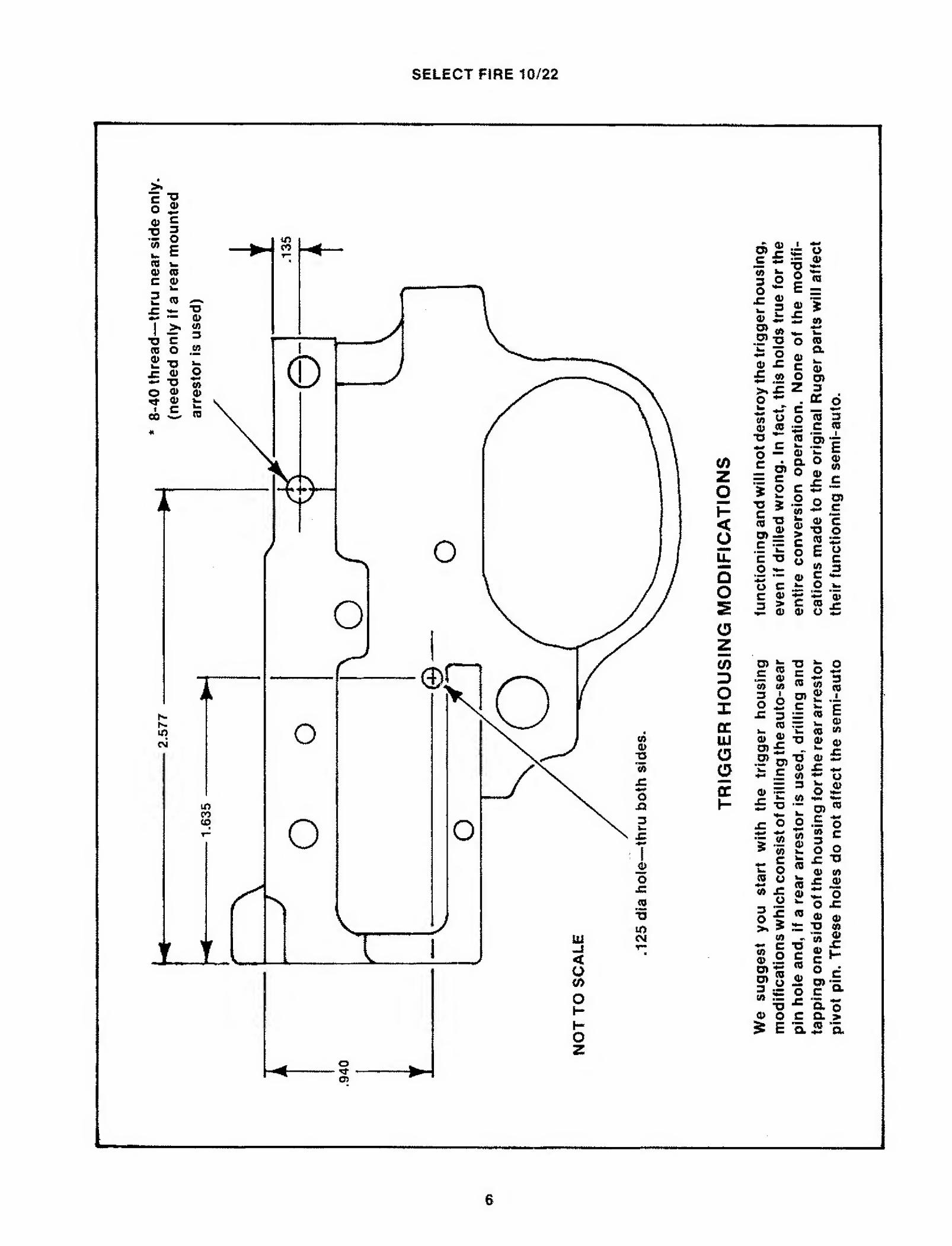
c ■° o ® ® § 2 g w I co w Q> CO c o
2 w ^
©
o
o
O
o o
d> ® i o c s = <» U «•« « J: o rn 3 o c ® o fc = f 3 » J 2> ~ £ « o> _ -r .?Soi
a O* T x ® k. a> -c c o> £ .2 ° o» SK £ Z 3
o - _■ “ o
<o <£ a? ,2 "O
c o — £ d>
o <3 S3 C « 2 JPe a o $ 0 2 c
> O C 4^ ^ w A
15 § ■o S>-2 c -r E T3 o ^ o c
i > tX 0)
•— W tf) ^ w
fe *> 5 i TJ o c «J ~ o E y «<« §
*•«* £ Ow tr £ a> l ro i* a> o z;
o ^ ._ a> CO 60
o 2 -C ^
CO aJ a> 05 £
.2* o>
<i> ^ £ "O
i * * CO «- c )= o CO u
CO
if 3 g □ .—
= o5
o> 2 .i C *m C = <0 = ik, 0) t « « "O (2) O . j£ ^ O «*<#
to sz +* <o o 3o£
” o> « o c ^ w “ c £ o O ffl ■=13 " fl> 10 <5 £ ® a> ^ o w O JC ® a> o) ^■o«
„ “S to « xi C®h ® o ® 0) “ a r
CO ■— T3
0) O ? E
s o c & o
C Q. >
a 5 a
6

SELECT FIRE 10/22
© CO CM
BO
LT
/AU
TO
-SE
AR T
RIP
PIN
LO
CA
TIO
N

SELECT FIRE 10/22
0
T> 0C C LU <0
5 1 o
HI t « w 2 t < r O
U 013
uj E 2 a. £ £ CC <j o o“e ^ "TZ c/> 2 « ui § ® C ” cc a < O
Q CO
5 c < .2 o -5. Ui o
Z < o
UJ £ OC <5 CC -O o <5 H c in 3 LU O CC E CC W < CO o
■o C £ « o
s # 2
« «?S1 h2 i 3 c O < o E
11
AU
TO
SE
AR
P
AR
TS V
IEW

SELECT FIRE 10/22
9

SELECT FIRE 10/22
Scale: 2:1
AUTO-SEAR
* The height of the sear surface is machined slightly high in order that it may be fitted to the mating sear notch on the hammer during final tuning.
T.E.K. auto-sears are made out of 0-1 oil hardening flat ground steel flats (3/16 x 1/2 stock). If you wish to use the same it can
probably be found at a local tool & die shop in small pieces. Otherwise, it normally comes in 18-inch lengths.
To heat treat, bring the piece to about 1,550 degrees F and quench in oil. Draw for at least 1 hour at 400 degrees F. You can use the kitchen oven for this. NOTE: Do not heat treat until all final tuning and adjusting is done.
4
10

SELECT FIRE 10/22
A
C
This photo of modified trigger housing reveals 3 things: The forward mounting pivot pin (A); The bolt release lever (B) which replaces the original bolt hold-open lever; The Mod 11 select lever (C) which is in the full auto firing position.
Trigger mechanism showing a Mod II select lever Installed.
sear trips. Try to determine the clearance even if it’s very wide. In all probability you will have to
bend the auto-sear tail forward. Don’t be afraid
to overbend because it’s much easier to bend it
rearward since it’s up against the hammer, but to bend it forward it must be removed from the trigger housing. If after bending, you find that
This photo shows the select lever moved into the semi-auto firing position.
Modifications to the original bolt are shown here. An auto-sear trip pin is added. The mill cut shown is used with a forward mounted arrestor.
you have no clearance, bend the tail rearward a little at a time until it falls within tolerance. A
small (4 inch) Crescent wrench is ideal to bend the sear tail with. The auto-sear should trip
between .010 and .015. After breaking all sharp
edges (careful with the sear surface), the auto¬ sear is ready to heat treat.
11

.414
SELECT FIRE 10/22
12

.07
5—
Th
is
is
a ra
ther
dif
ticu
it
area
to
mea
sure
.
SELECT FIRE 10/22
13
HA
MM
ER M
OD
IFIC
AT
ION
S (
Co
nt’
d)
SELECT FIRE 10/22
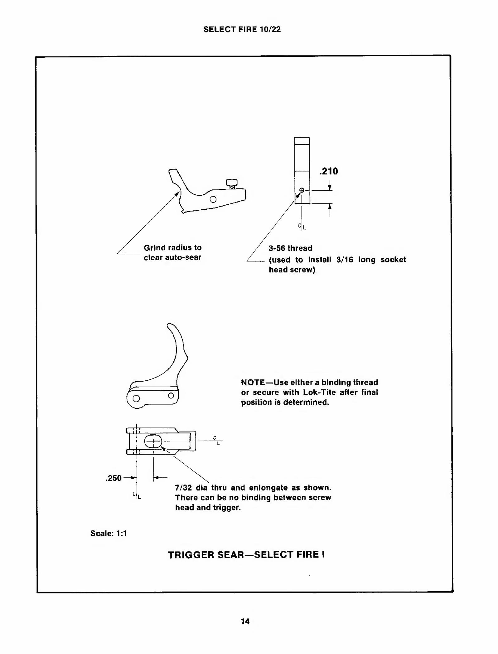
head screw)
NOTE—Use either a binding thread or secure with Lok'Tite after final position is determined.
.250 7/32 dia thru and enlongate as shown. There can be no binding between screw head and trigger.
Scale: 1:1
TRIGGER SEAR—SELECT FIRE I
14

SELECT FIRE 10/22
.187 radius.
sides,then finish drill to .093 dia.) .093 dia—thru
(Drawing may be used as a template except for hole location)
L
i
t .170
SELECT FIRE II LEVER
.170—H
.093 drill rod. Silver solder to lever.
A 1
.062
.475—H
* The .047 (max) deep flat on shaft is cut by hand with select lever in place assembled to trigger and held in semi-auto position. Do not cut beyond 1/2 the diameter ofthe shaft. Final fitting can be accomplished by reducing the height of the “A” surface of the trigger sear. In final fitting, the lever should move forward with no binding and cam trigger sear down against sear spring pressure.
TRIGGER SEAR MODIFICATION
Scale: 1:1
TRIGGER, TRIGGER SEAR & SELECT FIRE II LEVER


Full Auto Operation—Rear Mounted Arrestor
With a loaded magazine inserted, a round chambered. Select Fire II lever “1”forward and safety off, you are ready to fire full auto. The trigger is pulled (slight upward pressure is required on Select Fire I), the hammer drops and the gun fires.
The bolt starts the recoil cycle camming the hammer rearward which, with the bolt arrestor spring “4” attached, begins to exert lifting pressure against the arrestor actuating pin “6” attached to the bolt arrestor “7”. This spring lifting pressure is increased progressively as the hammer is cammed rearward. However, the bolt arrestor “7” is limited in its upward movement due to its contact with the bottom of the bolt. Just short of full recoil the auto-sear “3” is rotated rearward under spring pressure and is in position to catch the hammer on its auto-sear notch as the hammer starts to follow the bolt back in counter-recoil.
In counter-recoil the bolt strips another round from the magazine and chambers it. When the bolt is within .015 to .018 of battery position the bolt arrestor “7” will rise behind it. The bolt will make contact with the breech face of the barrel and start to bounce rearward, much like a
hammer striking an anvil. However, its bounce is limited to the .015 to .018 clearance between the lug on the arrestor and the back of the bolt which is measured when the bolt is fully closed.
While this was taking place another sequence was happening. When the bolt was .010 to .015 from battery position, the auto-sear trip pin “S'’ mounted to the bolt tripped the auto-sear off its sear notch on the hammer. Although these two sequences take place almost simultaneously, the bolt is allowed enough time to strike the breech face, bounce back against the arrestor lug and return to battery as the hammer is falling. Thus the hammer is allowed full access to the firing pin.
The hammer, in its fall, will describe an arc of about 60 degrees. When the hammer reaches about the last 20 degrees of this arc, the bolt arrestor actuator spring “4” will start to exert downward pressure on the arrestor pin “6”. This spring pressure increases during the last few degrees of the hammer’s movement, thereby lowering the arrestor away from the bolt in order to allow the bolt, in counter-recoil, to move back over it. (In the front mounted arrestor configuration, the bolt arrestor is

SELECT FIRE 10/22
18
SELECT FIRE 10/22
19

SELECT FIRE 10/22
20
. L
IFT
ING
SP
RIN
G
. A
RR
ES
TO
R C
AM
Fig
3.
SE
MI-
AU
TO
, F
RO
NT M
OU
NT
ED B
OL
T A
RR
ES
TO
R
DO
WN P
IN

SELECT FIRE 10/22
cammed down by the arrestor cam-down pin “12”.) The gun fires again and another cycle starts.
In semi-auto all of the foregoing takes place except when the auto-sear is tripped, the hammer falls only down to the trigger sear which catches
it and awaits the trigger being released and again squeezed. All full automatic operations within the gun take place before semi-auto.
You can readily see that Ruger’s original design has not been changed, only added to. All of the reliability is left in the gun.
21

22

Fitting Rear Arrestor To Bolt Clearance
Assemble the bolt in the receiver without the cocking handle and recoil spring. Place the arrestor on its pivot pin in the trigger housing and place the trigger housing in the action using the 2 receiver cross pins.
Push the bolt forward to the battery position. If the arrestor lug falls behind the bolt, measure the clearance between the bolt face and the barrel face. If the arrestor does not fall behind the bolt, check to see that it lies flat against the side of the t rigger housing. Using a small rod or screwdriver, attempt to push it into position behind the bolt—gently! If it doesn't go behind the bolt, disassemble and take a .010 to .015 cut off the arrestor lug and try again. Once the
i ru L—i This drawing may be used as a rough template to make the hammer bushing clearance cut. Be careful not to over-cut. The arrestor must stay in place behind the hammer bushing as it moves up and down. It must be cut deep enough to allow the top of the arrestor lug to retract enough to be level with the top of the trigger housing.
arrestor lug locks the bolt, you will know where you are since you can measure the bolt face clearance with feeler gauges. Attempt to get a nominal clearance of .020.

SELECT FIRE 10/22
24
SELECT FIRE 10/22
8*40 thread
1 .160
T Scale: 4:1
REAR ARRESTOR PIVOT PIN (Needed only if you are using the rear mounting arrestor)
The rear arrestor pivot pin is best made from #20 drill rod. However, it can be made from an 8-40 screw. There must be an unthreaded portion (.093) after the head is removed. This portion protrudes through the trigger housing for the arrestor to pivot on. These 8-40 gun screws will vary in hardness so the first step is to anneal. The diameter of these screws will vary from .161 to .162 dia. Since the pivot pin hole drilled in the arrestor will be .161 dla, you may have to machine a small amount off the screw to allow for a perfect fit. The arrestor
should pivot freely and yet have no slop. Fit the pin to the arrestor, not the other way around. A slot cut in the threaded end will assist tightening It in the trigger housing.
When complete, the screw can be rehardened and drawn to a dark blue color, 900 degrees F if you have an oven.
In the final assembly the pivot pin must be epoxied in the threaded hole of the housing. We suggest using either an aluminum or steel epoxy.

SELECT FIRE 10/22
s: x
m <£ "O ^ (D c o
i- « (0 <s> i. O
o ** 2 a» ^ “O
o o in
E 2 3 (A C 0) .= o
o o
o « i- i
a ° CC CC <r a < t o 5 ID £ t" 01 Z ^ 3 x i CM O n
CC = < ° > rr
E c e 0 2 5 O w *“ a>
i| 4 "O 3
?! g 51 • c « »
■Si- c © u £ S> « «T ■§ 9 O £ 5 o. cS CD U-
<r uj a <
|1
O CO
z °* ■S £, •— CD (A (0
2 c
C Ut ca £ r- C :b a> 5 E (0 (A £ <D — 5*0 <D T-
O ^ w O a* *•
=* 2 ■c o "O -c o e CM Q. S *7 « >
■o a cO o
o O
TJ — 3 * £ o ti 7: £ c w A .=
= s 3 ” O) o J_ O £ | 2 S ®o g £ o> .2* < ® *
o a. ■ o
(A c cc D) o c
<a '(ft o 3 3
« £ g> CO C jc
<0 3 0) O
a> w > a JQ <0 •v (0 O) a> o> c c c o ji "5
eft _ (0 CO n c (ft c c
CO
p a> -X
<
26

SELECT FIRE 10/22
* 0) O U O CA
y- CO . ^ . to
O c o
CM
CM m fl
<0 O
<0
27
RE
AR M
OU
NT
ED
AR
RE
ST
OR A
CT
UA
TO
R S
PR
ING
M
ade
from .
029
stock

SELECT FiRE 10/22
ADJUSTING THE REAR MOUNTED ARRESTOR ACTUATOR SPRING
Adjust the spring to approximately 40 degrees from hammer surface, as shown. Assemble the hammer to the trigger housing without hammer spring and strut. With the hammer in the upright position place arrestor on pin, Move hammer back to cocked position and lower arrestor to spring. Slip spring loop over arrestor actuator pin and lower hammer and arrestor
until ejector pin can be inserted over top of arrestor arm. The ejector pin limits upward travel of the arrestor. The spring angle in relation to the hammer should be adjusted so that it will start to apply downward spring pressure when the hammer is 20 degrees from vertical.

SELECT FIRE 10/22
.030 magazine latch plunger, since overall length has been shortened due to bending.
NOT TO SCALE
ALTERATION OF EJECTOR (Rear Mounted Arrestor Only)
Ejector must be annealed before bending. After completion, reharden and draw to 500 degrees F for 1 hour.
29

SELECT FIRE 10/22
30
Sin
ce th
e outs
ide
flan
ge
“A”
on
the
ham
mer
bu
shin
gs
ho
usi
ng
. B
rass
shi
m s
tock
, .0
20 th
ick,
wor
ks w
ell f
or
is o
nly
.075
thic
k a
nd t
he
arre
stor
is .
093
thic
k a
nd
the
spac
er.
A s
lav
e pi
n .1
56 d
ia x
.52
0 w
ill s
ave
a lo
t m
ust w
ork
ov
er t
his f
lange
and b
ehin
d t
he
larg
e of
tim
e in
ass
embli
ng
the
ham
mer
an
d s
pac
er i
nsi
de
flan
ge
“B”
it is
nec
essa
ry I
o pla
ce a
.020
th
ick
sp
acer
the
trig
ger
ho
usi
ng
, b
etw
een t
he
left h
amm
er b
ush
ing a
nd t
he
trig
ger

SELECT FIRE 10/22
31
AR
RE
ST
OR R
EL
EA
SE C
AM
(R
ear
Mo
un
ted A
rres
tor)
ak
e fr
om 3
/32
x 1/
2 fl
at g
round s
tock
.

SELECT FIRE 10/22
32

Fitting Front Mounted Arrestor To Bolt Clearance
The same basic procedure is followed as with the rear arrestor except a 3/16 diameter slave pin, .950 long, is used to assemble the arrestor and then replaced by pushing through the regular front receiver cross pin after the rear receiver cross pin has been installed. If the
ARRESTOR RELEASE LEVER (Optional) Make From 5/64 x 1/2 Flat Ground Stock.
This drawing may be used for template. Distance “A” is critical and must be carefully fitted to arrestor cut. The proper fit is a slight looseness when the arrestor is in the up position. There must be no binding. After fitting, polish both the arrestor cut and the lever end. The lever fits Into the original bolt lock slot and the visible end is shaped to match the bolt hold open lever that must be discarded. It may be necessary to clean the slot slightly with a flat needle file. After final fitting, harden.
A
Use this drawing as a rough template to shape cam surface. Final fitting of cam surface should be done by hand, so leave some extra metal.
Shown here is a small pin that has been added to the hammer. This pin trips the bolt arrestor as the hammer travels forward to strike the firing pin.
arrestor lug falls and locks the bolt when it is pushed into battery, measure the clearance between the bolt face and barrel face. The final clearance should be between .015 and .018. If the clearance is short, disassemble and place the bolt back into the milling machine and re-cut to bring the clearance to tolerance.

SELECT FIRE 10/22
Pivot pin hole
BOLT ARRESTOR
.062 HAMMER BUSHING SPACER
STANDARD RIGHT HAMMER BUSHING
NOT TO SCALE
D
\ Arrestor lilting spring
Arrestor cam-down pin
ALTERED LEFT HAMMER BUSHING
FRONT MOUNTED ARRESTOR PARTS VIEW
34

SELECT FIRE 10/22
FRONT MOUNTED ARRESTOR Make from 3/32 x 1/2 inch flat ground stock.
To fit cam surface “A” to arrestor cam-down pin attached to hammer, proceed as follows: Assemble into trigger housing using the front receiver cross pin. Insert the ejector pin through the trigger housing and arrestor. The ejector pin limits the arrestor movement. In the up position the arrestor lug should protrude .090 to .100 above the trigger housing.
Holding the arrestor in the up position, move the hammer forward. The cam-down pin should make first contact with arrestor cam surface when the hammer is 17 to 20 degrees from vertical. The cam surface curve from first contact with the pin to the fully cammed down position (hammer vertical) should describe a slight parabolic curve. The arrestor lug should be level with the top of the trigger housing when the hammer is vertical. Caution: At this time make sure that the bottom of the arrestor is not bottomed out against the hammer bushing or the ejector pin. There must be enough clearance to allow the hammer to move about 2 degrees past vertical. This will assure clearance between the cam-down pin
and cam surface movement downward. Other¬ wise, the pin will bend or break. With the bolt assembled in the gun, the hammer is limited in its forward movement to the vertical position by the back of the bolt. The ejector pin clearance hole in the arrestor may be enlarged slightly if more up or down movement is required to meet specifications.
Polish arrestor cam surface before heat treating. If you are using 0-1 oil hardening steel, draw arrestor for 2 hours at 900 to 925 degrees F after hardening. If you do not have equipment for this heat treating then make your arrestor from mild steel (flat ground stock) and case harden. Kasenit works well. Follow the directions on the can and give it 2 treatments. The arrestor takes a lot of stress at 1200 rounds per minute! The auto-sear can, also, be made from mild steel and case hardened. Mild steel flat ground stock can be had in both 3/16 x 1/2 and 3/32 x 1/2. It cannot be had in 5/64 thickness which Is needed to fabricate the arrestor release lever.
35
FIRE 10/22
36
1/16
R
SELECT FIRE 10/22
O 5
I- < 3 *0 O ®
tt 1
P o
o 3 « » i C to 0) *0 t > Q) IB O ^ O 3 CO
£ o r £ 2 £ Q, O O <f a >. o
CL) CO X jE a a>
£ j £ O Q |
T a> o -J ■? o zgc Of} >.£ £
■fc « ■c T} Q. 3 c a> o (0 55 >» __. Vl^H •>
85?
a
1 ^ c <o 2* s a> > o
o ■ ■Hi 1 5 <5 > CO o □ 2 o
£ £ O)
co a> Z to
2 & co 0> to T3 t CM CO -r-
? s 5 2 = to
E £ o >,
CO u> c
£ a * S'
O) C M CO'”
£ c « sis 2 « ^
^ r O >* n ■o § ® — « to — q> 2 2 O a <o a *• _ a> 5= c Xf w ° C C c — u o c to o 3 a> ~ <5 o o oi 0> m ft- £ 3 S d | £ « a 2 1 - « < o
Ti | 3 g §
2 -w 2 * O Cl
vr ■i to
(0 <D
a. ^ c E 2 Ol c ■o o .2 3 c c O Q cc ca CD to
o to a C co j®
o fl> o co co E co *2 c o
c/> 3 E
o a
o = C CO
37

The
lif
ting
spri
ng s
ho
uld
rel
ease
pre
ssure
on
th
e ar
rest
or
lift
ing
pin
just
bef
ore
the
ham
mer
m
ounte
d ca
m-d
ow
n
pin
conta
cts
the
cam
su
rfac
e of
the
arre
sto
r. T
he
ben
d a
t the
end
of
SELECT FIRE 10/22
o o a 2 75
c o
13 c
i t Vr
o o 05 2 o a a o « 01 05 <0 TJ
05 $ ■3
o c
O «
M
CO w> a. TJ 0) o O c
MM c 10 05
o ® ® fc- 3 w Q) M r- Z. ? 8 S ; ° a- £ £ • 5 S
22 Q k. O 52
c O o s
o X o a “ c
Q. S o £ O o a) c
‘3T *
£ & ~ K s * 3 O ° 05 o c „£ _ (ft 05 c £
E | Q 44 «5 2 0) w o * E 2 E
05 <C
.E c
o <o 4? ' a * 3 ° W <0
o ? a to C 0)
— « aD 05 kl £ O C *5 q)
< H . o
c o
05 S £ - ~ « £ 5 4M a> o £ a
X5 -o w j a» i o a> C o h o o H a> « o
*o — £ « 5 ^ co a> O TJ o o
#S3 = < f JP «
a 2 2 SI
c ® £ a a 3. 05 > <y 2 £ co
O O £ o c *. o <s>
0) .
a E <p E 05 CO
</5 £ L. i
o o m
38
AD
JUS
TIN
G T
HE F
RO
NT
MO
UN
TE
D A
RR
ES
TO
R L
IFT
ING
SP
RIN
G

.062
SELECT FIRE 10/22
39

SELECT FIRE 10/22
Altered parts for front mounted arrestor. As stated in text, there are advantages to both front and rear mounted arrestors, with the final choice being determined mainly by the machining facilities and expertise available to the person doing the conversion.
Photo of a prototype front mounting arrestor. This prototype differs slightly from the drawing and has extra lightening holes added.
* YJ u I
jf vS-’.
[A. 1. w
a fcf'■ J 1 #; * % * ♦*• * •. - -

ADDENDUM
(The following was an instruction sheet supplied by the TEK plant when they were producing these converted Ruger 10/22's.)
The bolt lock and spring have been removed from your gun to make room for the conversion parts, otherwise the gun utilizes all the remaining parts and operates just as it came from the Ruger factory in the semiauto mode. In the full-auto mode it still operates as it came from the Ruger factory except the sear is operated automatically by the cycling bolt as long as the trigger is held back. Twenty-two ammo is greasy, waxy and has a tendency to leave a lot of fouling behind in the action. It is not, however, necessary to completely disassemble the gun for normal cleaning. It is prudent to clean the action after about 500 rounds by retracting the bolt and placing a wooden dowel of about 3/16-inch diameter by 1%-inch long between the bolt face and the breech end of the barrel to hold the bolt open since the bolt lock is no longer in the gun.
With an old toothbrush or something similar dipped in Hoppes, WD-40, etc., scrub the bolt face and parts of the action that you can reach. Pay particular attention to the recessed bolt face and extractor slot in the barrel. Dry with a lint free rag or cleaning patch. Q-tip sticks are handy for cleaning. Spray very lightly or wipe down with Break Free, WD-40, etc. Clean the barrel in the normal fashion but, leave a dry chamber as you should with any rifle. With such cleaning, your gun should function properly for thousands of rounds.
If and when you must break the gun down completely, follow the procedure described here to prevent possible damage to the parts. The bolt arrestor lifting spring which is attached to the hammer MUST lay on the right side of the long arm of the auto-sear spring. Looking down on the trigger housing, the parts and spring should be as follows, from left to right: Bolt arrestor, ejector, long arm of auto-sear spring set behind the ejector
pin, bolt arrestor lifting spring. When all parts have been cleaned and reassembled in the trigger housing, using the 3/ 16-inch diameter slave pin supplied, lay the barrel and action on the bench, barrel pointing to your left, action upside down. Using the bolt handle, retract the bolt about 1/2-inch and place an empty .22 case between the bolt and barrel face to hold the bolt partially open. Place trigger housing into the receiver and insert the rear receiver cross pin. Insert the front cross pin, pushing out and replacing the slave pin. Both cross pins are push fits—DO NOT FORCE. CAUTION—the front cross pin must be inserted going away from you, or, in other words, from the bolt handle side (closest to you), through to the serial number side. The reverse of this procedure can damage the bolt arrestor which is fitted to close tolerances.
Wear shooting glasses and keep other people clear of the right side of the gun when shooting. Empty, hot cases really flow from the 10/22 in full-auto. Extractors have, also, been known to blow off 10/22’s. Have fun but be careful, the firepower of this gun is awesome.
You can remove all TEK parts, replace the bolt lock and spring, and your gun works just like the original.
The original bolt lock has been replaced with a look-alike lever that retracts the bolt arrestor. Pull back on the lever to retract the arrestor to open the bolt when the hammer is cocked. This allows you to unload the gun if there is a round in the chamber.
To adjust the rate of fire, use the Allen wrench supplied and tighten until the bolt will just stay open when retracted by the bolt handle. This is the ideal slow fire setting, although you can adjust it slower. To insure better reliability, test fire under extreme weather (hot and cold) conditions.
CAUTION: The bolt cannot be opened if the hammer is down and the safety is on. You must place the safety on fire position to open the bolt when the hammer is in the fired position.
41