LOS ANGELES COUNTY FIRE DEPARTMENT FIRE STATIONLOS ANGELES COUNTY FIRE DEPARTMENT FIRE STATION
description

1
FIRE

2
Fire fighting on board ship can be defined in three separate categories:
Fire protection, by design features in the construction of the vessel and subsequent control of human behaviour
Fire Detection, using artificial systems or human senses.
Fire suppression using a number of fixed or portable systems.

3
All fire fighting starts with the idea of what is needed for FIRE

4
All fire fighting breaks the triangle
REMOVAL
Or
STOPPAGE
Reduce to less than 10% Oxygen
5
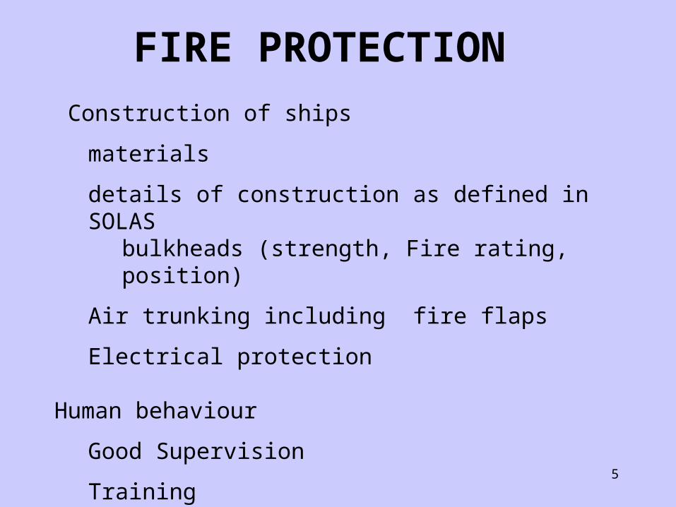
Construction of ships
materials
details of construction as defined in SOLAS bulkheads (strength, Fire rating, position)
Air trunking including fire flaps
Electrical protection
Human behaviour
Good Supervision
Training
FIRE PROTECTION
6
Fire detection systems are compulsory in ships which have periodically unattended machinery spaces.
FIRE DETECTION

7
A fire detection system consists of the following elements:
Human observation
Manual fire alarms
Automatic Fire detectors-smoke, flame, heat (gas, H2S)
Combinations of the above
For reference purposes Fire detection system requirements are detailed in SOLAS CHAPTER II-2
FIRE DETECTION

8
Human observation relies on the human senses:
Sight
Sound
Smell
Taste
Touch
FIRE DETECTION

9
Most Human observations can be mimicked by the following detectors
Sight-
Infra red flame detectors, sensing flicker patterns, smoke detectors using light sources in “go” or “no go” light transmission and reception.
Smell and Taste-
combustion products entering an ionized chamber.
Touch-
Heat detectors, including absolute temperature and rate of rise temperatures.
FIRE DETECTION

10
Manual systems usually involve some form of manual fire patrol. The question about fire patrols is the only common question occurring in class 1 deck and class 1/2 motor.
Call points, a recognised route, regular communications, timing and record keeping are essential.
FIRE DETECTION

11
Automatic Fire detection
An automatic fire detection system has the following components
1. Electrical feed, both normal and emergency (including battery backup)
2. Main control unit (usually housed in the wheelhouse( with repeater units
3. Fire detection sensors and manual call points
4. Electrical circuits to connect 1,2 and 3.
FIRE DETECTION

12
Detector Units
Detector units detect outbreak of fire by sensing
Heat
Smoke
Flame
Detector heads are positioned throughout the vessel, in machinery, accommodation and in some cases, cargo spaces.
FIRE DETECTION

13
Detector Units
On some systems each individual detector head has its own address, so that in the event of an alarm detection, the head position is indicated on the control panel and the seat of the fire is determined
Overall Fire alarms are automatically sounded, usually by the activation of one alarm.
FIRE DETECTION

14
A simplified view of the layout of a fire detection system, featuring normal/emergency power supply, UPS,Loop,Zone Indicators, Alarms, Test switch and Fire Zones.
FIRE DETECTION
15
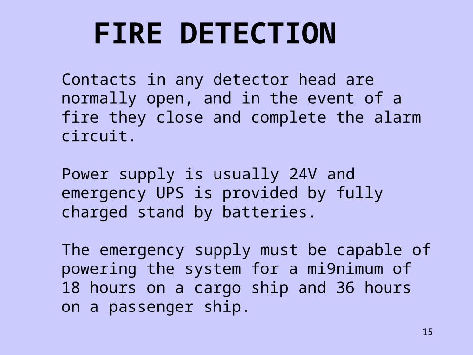
Contacts in any detector head are normally open, and in the event of a fire they close and complete the alarm circuit.
Power supply is usually 24V and emergency UPS is provided by fully charged stand by batteries.
The emergency supply must be capable of powering the system for a mi9nimum of 18 hours on a cargo ship and 36 hours on a passenger ship.
FIRE DETECTION
16
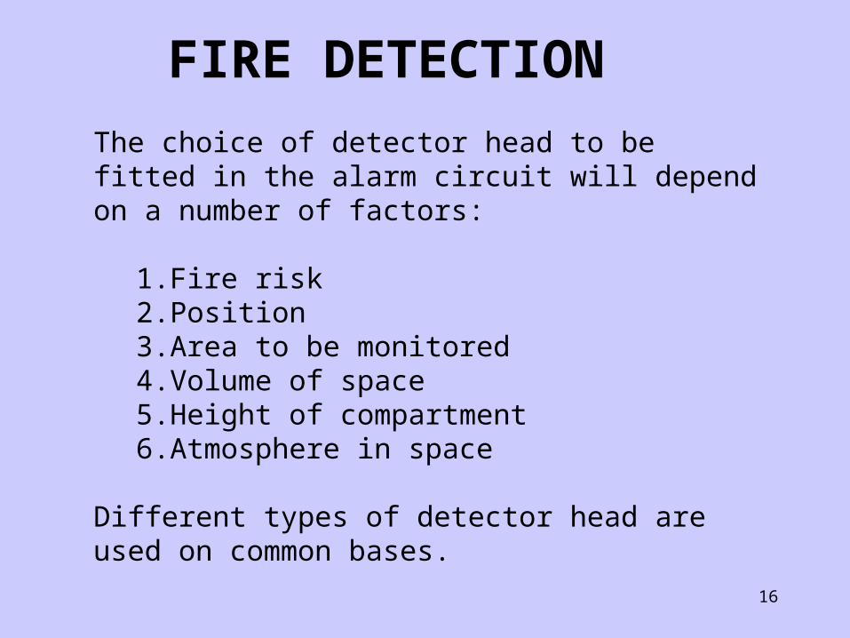
The choice of detector head to be fitted in the alarm circuit will depend on a number of factors:
1. Fire risk2. Position3. Area to be monitored4. Volume of space5. Height of compartment6. Atmosphere in space
Different types of detector head are used on common bases.
FIRE DETECTION

17
Smoke detectors must not operate below 2% obscuration per metre, but must activate before 12.5% obscuration.
Heat detectors must not operate below 540C but must operate before 780C.
However, in certain cases the heat detector limits may be increased by 300C
FIRE DETECTION

18
SENSOR OPERATING PERAMETERS
Type AREA ( MAX) DISTANCE APART
DistanceFrom Bulkhead
HEAT 37m2 9m 4.5m
SMOKE 74m2 11m 5.5m
FIRE DETECTION

19
Smoke and heat detectors must also be sited to avoid stratification: that is the detector must not be blanketed by layers of hot air.
FIRE DETECTION

20
In this case, the increasing convection air currents have created a flow of combustion products across the detectors.
FIRE DETECTION

21
As shown, detector heads must be positioned to allow easy passage of combustion products in all fire scenarios
FIRE DETECTION

22
HEAT DETECTION
BI METALLIC STRIP
FIRE DETECTION

23
HEAT DETECTION
RATE OF RISE:
TWO BI METALLIC STRIPS
FIRE DETECTION

24
HEAT DETECTION
RATE OF RISE:
TWO BI METALLIC
STRIPS
FIRE DETECTION

25
HEAT DETECTION
RATE OF RISE:
TWO BI METALLIC
STRIPS
FIRE DETECTION

26
HEAT DETECTION;RATE OF RISE:PNEUMATIC
FIRE DETECTION

27
FIRE DETECTION

28
FIRE DETECTION

29
SMOKE DETECTION
IONISATION
RADIOACTIVE SOURCE
AMERICIUM
FIRE DETECTION

30
NORMAL
In normal conditions, the Ions “flow” easily across the air gap and thus maintain an electric circuit.
FIRE DETECTION
31
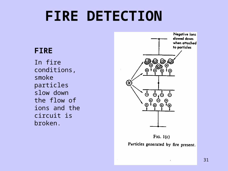
FIRE
In fire conditions, smoke particles slow down the flow of ions and the circuit is broken.
FIRE DETECTION

32
SMOKE DETECTION: DEFLECTION OF LIGHT- “GO”
FIRE DETECTION

33
NORMAL CONDITION “NO-GO”
FIRE DETECTION

34
FIRE CONDITION “NO-GO”
FIRE DETECTION

35
LIGHT OBSCURATION - PHOTO ELECTRIC CELL
FIRE DETECTION
36
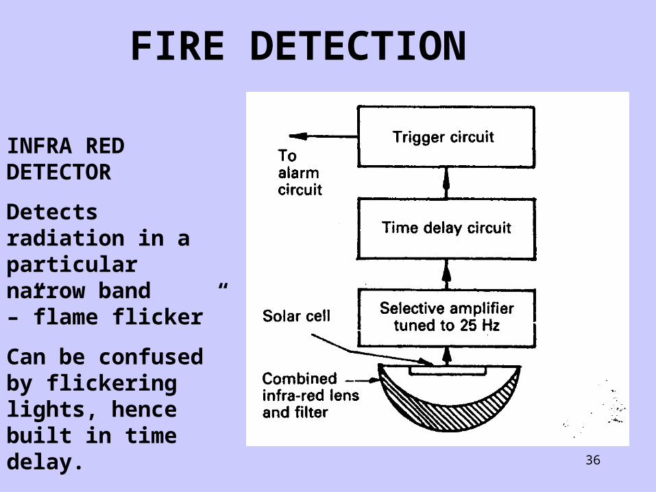
INFRA RED DETECTOR
Detects radiation in a particular narrow band –”flame flicker”
Can be confused by flickering lights, hence built in time delay.
FIRE DETECTION

37
This multi wavelength flame detector is monitoring the flame generated when a hydrocarbon mixture burns.
FIRE DETECTION

38
FIRE DETECTION
This slide shows how different components in a fuel mixture generate different radiation wavelengths-the different colours in a flame.

39
FIRE DETECTION
The overall flame appearance consists of a number of wavelengths.
Most marine flame detectors detect the wave length of carbon dioxide produced in combustion ( just like human vision)

40
FIRE DETECTION
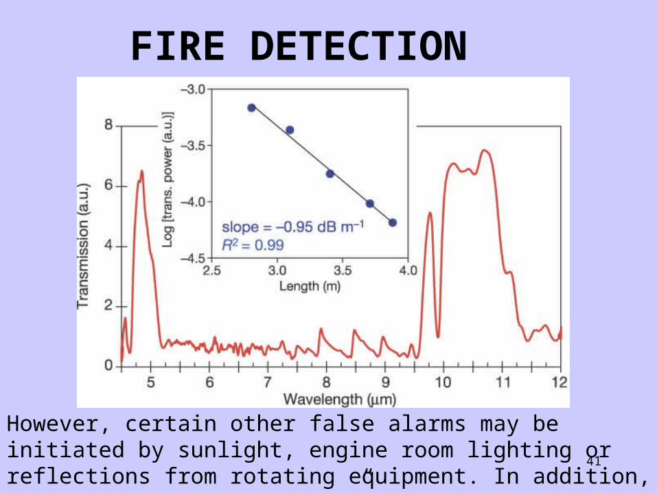
The filter only allows wavelengths in a certain bandwidth to pass through-this prevents false alarms from other sources.
41
However, certain other false alarms may be initiated by sunlight, engine room lighting or reflections from rotating equipment. In addition, the detector may be “blind” from smoke.
FIRE DETECTION

42
This detector must not be used as a stand alone unit, but in conjunction with other types of detector.
Its positioning must be chosen carefully, usually above a slow speed engine.
FIRE DETECTION

43
This detector senses the ultra violet spectrum of a flame and is less sensitive to false alarms.
FIRE DETECTION

44
TESTING A SMOKE DETECTOR

45
CABLE LAYOUT
LOOP and LINE
Monitoring
LOOP MONITORING
The continuity of the cable is checked by both circuits a-d and b-c.
In the event of either cable failing due to damage the an alarm sounds.
FIRE DETECTION

46
CABLE LAYOUT
LOOP MONITORING
Failure modes-damage causes open or short circuit on cables.
Short circuit, no discrimination between faults and FIRE activation.
Open circuit, fault alarm on one wire
FIRE DETECTION

47
CABLE LAYOUT
LOOP MONITORING
In each case faults must be examined immediately
Whilst the fault condition exists subsequent fire detection is inhibited
Easier for accurate fault detection, discriminates between fault and fire but more expensive.
FIRE DETECTION

48
Line monitoring: Damage to loop
Short circuit shuts down the system and gives Fire alarm.
Open circuit raises fault indication
Less reliable, harder to pinpoint faults but cheaper.
FIRE DETECTION

49
When the reference resistance becomes LESS than the end resistance ( due to heat effect on cables) the FIRE alarm sounds. When reference resistance is GREATER than the end resistance a Fault alarm sounds.
FIRE DETECTION

50
Fire Zones
The system is subdivided into ZONES to allow easy identification of the seat of the Fire.
Clear information must be displayed near the panel which shows the actual location of the Fire source or the location may be directly displayed on a MIMIC panel.
FIRE DETECTION

51
Fire Zones
Regulations covering Fire detection are set out in SOLAS Chapter II-2, Regulation 13, Section 1.
Point 1.15 concerns modifications made to detection systems post 10/94 and deals with single addressable heads.
Section 2 deals with Installation requirements including details of areas to be monitored.
FIRE DETECTION

52
FIRE FIGHTING SYSTEMSCurrently, the classifications of Fires are as follows
Class A SOLIDS or Carbonaceous fires
Class B Liquids or LIQUIFIABLE solids
CLASS C Gases
CLASS D Metals
CLASS E Electrical Equipment
Class F Cooking Oil or Fat
53
All fire fighting systems are used to either:
Remove Heat
Remove Oxygen
Remove fuel
or
CHAINBREAK-stop the chemical reaction
FIRE FIGHTING SYSTEMS
54
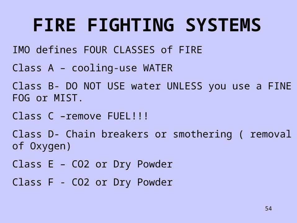
IMO defines FOUR CLASSES of FIRE
Class A – cooling-use WATER
Class B- DO NOT USE water UNLESS you use a FINE FOG or MIST.
Class C –remove FUEL!!!
Class D- Chain breakers or smothering ( removal of Oxygen)
Class E – CO2 or Dry Powder
Class F - CO2 or Dry Powder
FIRE FIGHTING SYSTEMS

55
How is Heat Removed from a Fire
WATER
Freshwater
Sprinklers, curtains and “Hi Fog”
Seawater (via fire-pumps)
Hydrants, hoses, coarse sprinklers (and drenchers!) and fire mains ( hoses, hydrants and nozzles)
FIRE FIGHTING SYSTEMS

56
FIRE MAIN
A sea water supply system to fire hydrants is fitted to every ship. Several pumps in the engine room will be arranged to supply the system, their number and capacity being dictated by legislation (MCA for UK registered vessels as well as LLOYDS RULES)
An emergency fire pump will also be located remote from the machinery space and with independent means of power.
A system of hydrant outlets, each with an isolating valve, located around the ship, and hoses with appropriate snap-in connectors are strategically located together with fire hose nozzles.
FIRE FIGHTING SYSTEMS

57
Fire Hose Nozzles
These nozzles are usually of the jet/spray type providing either type of discharge as required. All the working areas of the ship are thus covered, and a constant supply of seawater can be brought to bear at any point to fight a fire.
While sea water is best used as a cooling agent in fighting Class A fires it is possible, if all else fails, to use it to fight Class B fires.
The jet/spray nozzle would be adjusted to provide a fine water spray which could be played over the fire to cool it without spreading.
FIRE FIGHTING SYSTEMS

58
International Ship Shore Connection
An international shore connection is always carried on board ship. This is a standard size flange which is fitted with a coupling suitable for the ship's hoses.
FIRE FIGHTING SYSTEMS

59
FIREMAIN LAYOUT
FIRE FIGHTING SYSTEMS
60
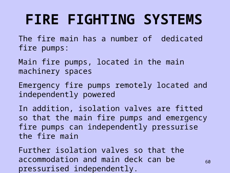
The fire main has a number of dedicated fire pumps:
Main fire pumps, located in the main machinery spaces
Emergency fire pumps remotely located and independently powered
In addition, isolation valves are fitted so that the main fire pumps and emergency fire pumps can independently pressurise the fire main
Further isolation valves so that the accommodation and main deck can be pressurised independently.
FIRE FIGHTING SYSTEMS

61
Hydrants are located around the deck, and each hydrant is equipped with a Fire hose and adjustable fire nozzle.
Materials used, types of hydrant connection and further equipment are subject to CLASS rules,
SOLAS merely gives a broad definition of what should be fitted- class provides the technical expertise for the detailed construction.
Certain areas, such as the paint locker are protected by manually operated spray systems, supplied by the Fire main.
FIRE FIGHTING SYSTEMS

62
Tankers and Passenger vessels have a requirement for constant pressurisation of the fire main using “ jockey” pumps and a pneumatic pressure system, with main fire pumps stated manually or automatically.
Tankers on specific operations, which may involve high sulphur fuel, can be equipped with water drencher systems to cover the accommodation and protect it from hydrocarbon gas or H2S releases
Other specalised vessels provide manual water curtains at lifeboat embarkation points.
FIRE FIGHTING SYSTEMS
63
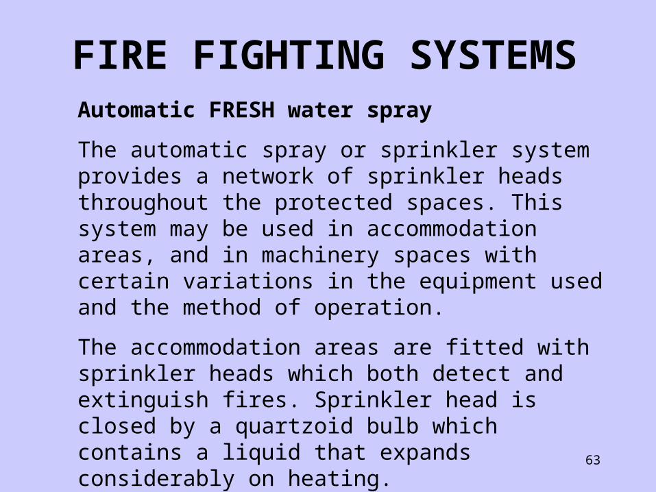
Automatic FRESH water spray
The automatic spray or sprinkler system provides a network of sprinkler heads throughout the protected spaces. This system may be used in accommodation areas, and in machinery spaces with certain variations in the equipment used and the method of operation.
The accommodation areas are fitted with sprinkler heads which both detect and extinguish fires. Sprinkler head is closed by a quartzoid bulb which contains a liquid that expands considerably on heating.
FIRE FIGHTING SYSTEMS

64
Automatic FRESH water spray
When excessively heated the liquid expands, shatters the bulb and water will issue from the sprinkler head. A deflector plate on the sprinkler head causes the water to spray out over a large area.
FIRE FIGHTING SYSTEMS
65
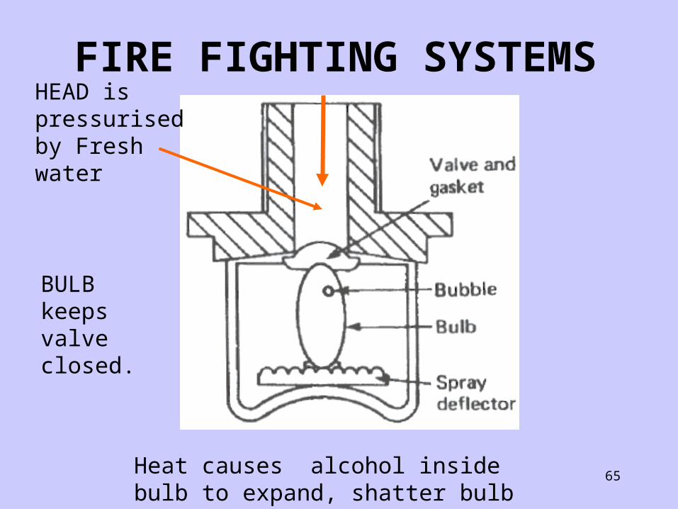
HEAD is pressurised by Fresh water
BULB keeps valve closed.
Heat causes alcohol inside bulb to expand, shatter bulb and water flows.
FIRE FIGHTING SYSTEMS
66
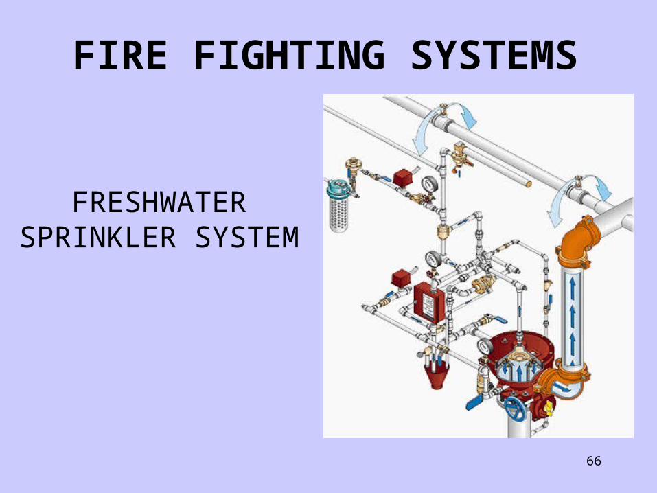
FRESHWATER SPRINKLER SYSTEM
FIRE FIGHTING SYSTEMS
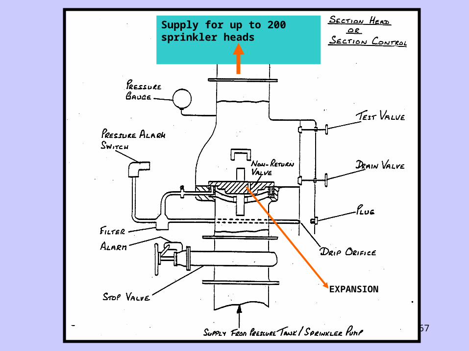
67
EXPANSION
Supply for up to 200 sprinkler heads
68
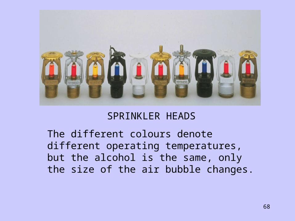
SPRINKLER HEADS
The different colours denote different operating temperatures, but the alcohol is the same, only the size of the air bubble changes.

69
Typical low pressure sprinkler
system
NOT HIGH FOG
FIRE FIGHTING SYSTEMS

70
HIGH FOG
Cool and smother, using the latent heat properties of water to cool, and expansion into steam to temporarily remove oxygen.
Devised by Marioff, from an initial requirement by the Belgian air force, Marioff converted a hydraulic system of 200 bar pressure to water in 1974.
FIRE FIGHTING SYSTEMS
71
HIGH FOG
Development then followed on head technology, and pressures have reduced drastically. The following slide shows a “GL” approved hi fog system currently fitted to new build container ships.
A single stage low pressure centrifugal pump, with a screw inducer fitted in the eye takes suction direct from the domestic fresh water tank.
FIRE FIGHTING SYSTEMS

72
FIRE FIGHTING SYSTEMS
73
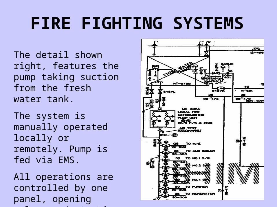
The detail shown right, features the pump taking suction from the fresh water tank.
The system is manually operated locally or remotely. Pump is fed via EMS.
All operations are controlled by one panel, opening valves and starting pump.
FIRE FIGHTING SYSTEMS

74
Hi Fog droplets are extremely small, increased surface area causes them to flash into steam, latent heat is absorbed, steam generated displaces oxygen.
FIRE FIGHTING SYSTEMS

75
MARIOFF tested their Hi Fog systems on a carbonaceous fire, and estimated the use of 150 litres of water in a Hi fog system is as effective as 7000 litres in a sprinkler system:
46.67 to 1 !!!
FIRE FIGHTING SYSTEMS

76
SMOTHERING
Removal of Oxygen
FOAM
Simple foam installation, with seawater mixing with foam compound(usually protein).
FIRE FIGHTING SYSTEMS

77Exact metering of foam compounds and water.
FIRE FIGHTING SYSTEMS

78
Types of foam available for marine use:
Protein base ( PF)
Flouro protein foam (FP)
Film forming fluoro protein foam (FFFP)
Synthetic detergent foam
Alcohol resistant foam-chemical fires
Aqueous film forming foam ( AFFF)
FIRE FIGHTING SYSTEMS

79
A simple CO2 driven foam system
FIRE FIGHTING SYSTEMS

80
Hi-Ex- has limited use due to lightness of foam. Convection currents can easily blow the foam away. Must be delivered from overhead nozzles
However you can breathe in the mixture, and there is a limited cooling and smoke clearing effect.
FIRE FIGHTING SYSTEMS

81
CHAINBREAKERS
HALON
Still legal under IMO legislation but not UK legislation ( or other EU countries
plus CANADA)
NOVEC 1230 is an approved drop in
replacement.
FIRE FIGHTING SYSTEMS

82
HALON is a CFC and so has the same OZONE depletion affect as R11 and R12.
NOVEC 1230 is a HALON replacement, using roughly the same pipeline layout, and same mass of fluid, with a slight change in head detail, and with an ODP and GWP of 0.
FM 200 requires roughly 1.5 times as much mass as HALON, has an ODP of 0 and a GWP of 1
PYROGEN has appeared briefly as a HALON substitute but has since disappeared.
Dry powder is also a chain-breaker and in addition acts as a smothering agent.
FIRE FIGHTING SYSTEMS

83
Flammable Range

84
The flammable range is relatively narrow, so that any new gas introduced into the space will either displace oxygen or remove hydrocarbon vapours.
This particular example is for crude oil, but the principle applies to all hydrocarbon based fuels.
Flammable Range