Fire test of ventilated and unventilated wooden façades
80
Fire test of ventilated and unventilated wooden façades Lars Boström, Charlotta Skarin, Mathieu Duny, Robert McNamee SP Report 2016:16 SP Technical Research Institute of Sweden
Transcript of Fire test of ventilated and unventilated wooden façades
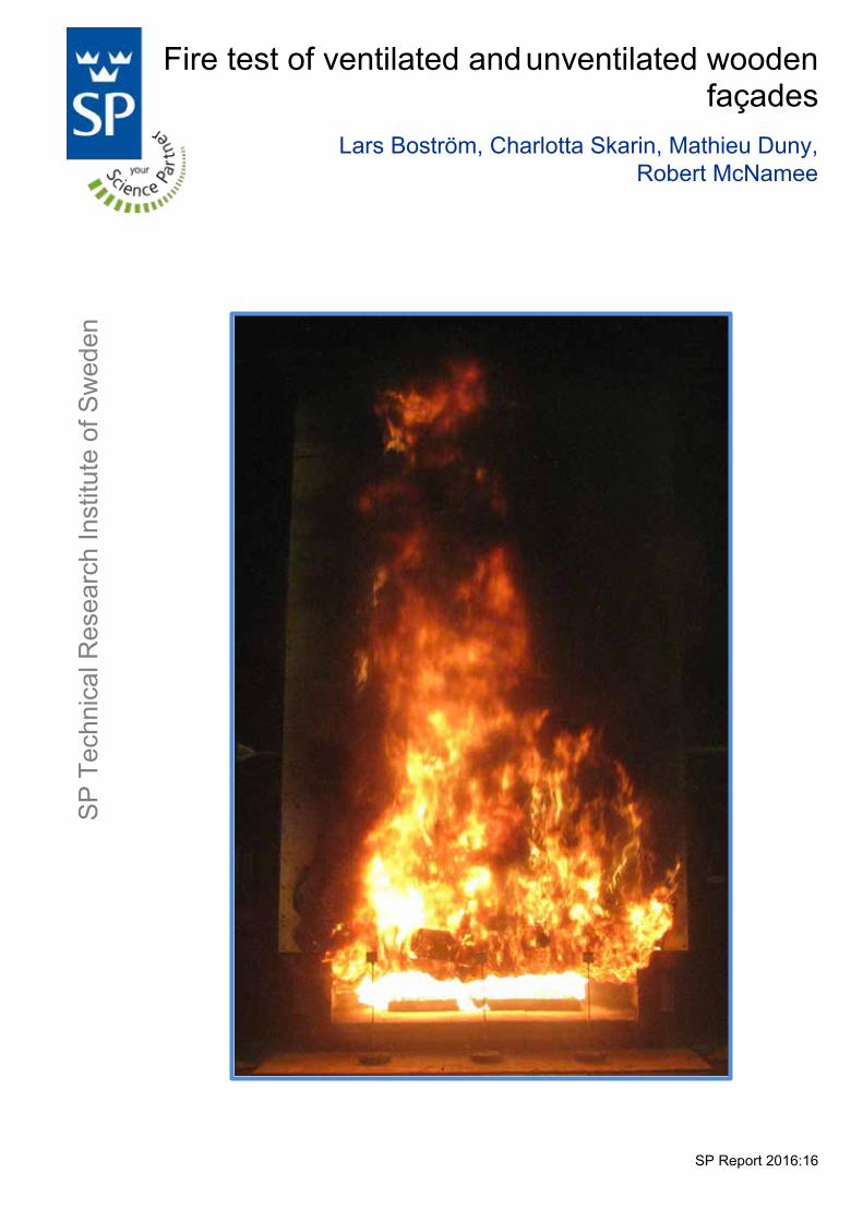
Fire test of ventilated and unventilated wooden façades
Lars Boström, Charlotta Skarin, Mathieu Duny, Robert McNamee
SP Report 2016:16
SP
Tec
hnic
al R
esea
rch
Inst
itute
of S
wed
en
Fire test of ventilated and unventilated wooden façades Fire test of ventilated and unventilated wooden façadesFire test of ventilated and unventilated wooden façades Lars Boström, Charlotta Skarin, Mathieu Duny, Robert McNamee
3
© SP Sveriges Tekniska Forskningsinstitut AB
Abstract Fire test of ventilated and unventilated wooden façades Three large scale façade tests in accordance with SP Fire 105 as well as an ad hoc SBI test have been carried out. The façade tests included an inert façade made of lightweight concrete, one façade with a plywood cladding and finally a façade with plywood cladding with a fully ventilated cavity behind the cladding. The SBI test was made with plywood without ventilation cavity. The aim of the tests was to perform well controlled tests with numerous of measurements including heat release rate, heat from the combustion chamber, temperature on the façade surface, heat flux, plume temperatures and temperatures in the ventilation cavity. The results from the tests will be used for validation of simulation techniques as well as input for further development of the façade test methodology. Conclusions from the study were that the surface temperature for charring of the plywood cladding in this configuration was in the region of 300 °C and that the energy release originated from the façade during the test was almost twice as high when there was a 20 mm wide cavity behind the plywood cladding. Key words: fire test, facade, wood, ventilation cavity SP Sveriges Tekniska Forskningsinstitut SP Technical Research Institute of Sweden SP Report 2016:16 ISBN 978-91-88349-20-0 ISSN 0284-5172 Borås 2016
4
© SP Sveriges Tekniska Forskningsinstitut AB
Contents
Abstract 3
Contents 4
Preface 5
Summary 6
1 Introduction 7 1.1 Background 7 1.2 Limitations 7
2 Experimental setup – SP Fire 105 9 2.1 Test method 9 2.2 Test specimens 11 2.3 Instrumentation and measurements 11
3 Experimental setup – SBI 14
4 Test results 16 4.1 General observations 16 4.2 Fire source 20 4.3 Heat release rate 23 4.4 Thermal exposure on the façade above the combustion chamber 24 4.5 Thermal exposure and heat flux one storey above the combustion chamber 25 4.6 Thermal exposure two storeys above the combustion chamber 27 4.7 Surface temperature 28 4.7.1 Temperature 1500 mm above the combustion chamber 28 4.7.2 Temperature 2700 mm above the combustion chamber 31 4.7.3 Temperature 3450 mm above the combustion chamber 34 4.7.4 Temperature 4200 mm above the combustion chamber 37 4.7.5 Temperature 5400 mm above the combustion chamber 40 4.8 Plume temperature at different heights 43 4.8.1 Plume temperature 1500 mm above the combustion chamber 43 4.8.2 Air temperature 2700 mm above the combustion chamber 47 4.8.3 Air temperature 3450 mm above fuel source 51 4.8.4 Air temperature 4200 mm above combustion chamber 55 4.8.5 Air temperature 5400 mm above combustion chamber 59 4.9 Temperature below the eave 63 4.10 Results from SBI test 65
5 Analysis and discussion 70 5.1 Fire source 70 5.2 Fire spread on the surface 71 5.2.1 Position of measurements 71 5.2.2 Measurement of fire spread on a material 71 5.3 Effect of ventilation cavity 76
6 Conclusions 78
7 References 79
5
© SP Sveriges Tekniska Forskningsinstitut AB
Preface The façade is an important part of a building. It forms the envelope of the building, and has several functions. When combustible materials are used, or there are other risks in case of fire, i.e. large parts of the façade may fall down, it is necessary to evaluate the behavior of the façade when exposed to fire. The present project has mainly been an experimental study, involving large test specimens. We would like to thank the eminent group of technicians who have taken care of all practical details within a very pressed time schedule, no one named, no one forgotten. We would also like to thank Mr. Pär Johansson for valuable discussions on what, how and where to do all the different measurements and what the results might represent. The project is part of a collaboration between Centre Scientifique et Technique de Bâtiment (CSTB) in Paris, France, and SP Fire Research in Borås, Sweden, who both have financially supported the study.
6
© SP Sveriges Tekniska Forskningsinstitut AB
Summary Three well documented façade fire tests in accordance with SP Fire 105 have been carried out. The tests consisted of one inert façade, one façade with a plywood cladding and finally one façade with a plywood cladding with a fully ventilated cavity behind the cladding. In all three tests numerous of measurements were made such as heat release rate, heat from the combustion chamber, surface temperatures, plume temperatures, heat flux, and temperatures in the ventilation cavity. In addition to the full scale façade tests, a SBI test was made in order to evaluate how flame spread on the surface can be determined by temperature measurements. There are some different aims with the study. Firstly, the experiments should be well documented and measurements should be done so the results can be used for validation of different simulation techniques, such as CFD (Computational Fluid Dynamics) modelling. Another aim was to assemble good data for the ongoing development of the next generation façade test methodology. Currently there are many different façade test methods, often national methods, which makes it difficult for industry. There is thus a demand for a harmonized test method. In the present study techniques for measurement of flame spread on a surface as well as how to measure or determine the heat exposure to the test specimen has been investigated. The present report is mainly an assembly of test results and a description of the tests carried out. The analysis of the results is limited, and more extended analysis will be published elsewhere. Furthermore, the tests made are limited to one type of combustible material, i.e. plywood, and thus more data will be needed for validation of the technique to measure fire spread on the surface and in cavities. Conclusions from the study were that the surface temperature for charring of the plywood cladding in this configuration was in the region of 300 °C and that the energy release originated from the façade during the test was almost twice as high when there was a 20 mm wide cavity behind the plywood cladding.

7
© SP Sveriges Tekniska Forskningsinstitut AB
1 Introduction 1.1 Background Façades are important from several perspectives for a building. It forms the envelope of the building and shall thus be the protection towards the outdoor climate, it is an important part controlling the energy demand of the building and it is also the face of the building and has thus architectural requirements. The façade has thus a number of functions for the building. During the last decades the use of combustible materials in buildings has increased, partly as a consequence of higher demands on energy efficient buildings. In order to determine the fire risks for different types of façade systems a good and reliable test methodology is needed. There are presently a large number of different test methods used around the world [1] which all have certain advantages but also disadvantages. In Sweden the test method SP Fire 105 [2] is currently used, but it is currently under a major revision. The Swedish test method was originally developed in the middle of the 1980-ties as a part of a large study including burning of 14 façades with a fully developed room fire as a heat source [3]. The fire exposure was optimised in the SP Fire 105 test to correspond to the large test. In the large scale tests the fire load density was 110 MJ/m2 of total surface area of the enclosure. The enclosure dimensions were 4 x 2.2 x 2.6 m3 with the opening factor 0.06 m1/2. During the tests approximately 50% of the fuel was burning outside the chamber. This factor is dependent on the geometry of the enclosure and on fuel parameters such as composition and geometry. In the SP Fire 105 test the fire source is 60 litres of heptane burning in trays with attached flame suppressors. The present study has the aim to give input data for the revision of SP Fire 105 as well as contribute with valuable data for validation of CFD modelling (Computational Fluid Dynamics). Another part of the study is to measure the difference in flame spread of combustible façade claddings with and without a ventilation cavity. One important aspect is how the flame spread on the surface, and in the cavity shall be determined. Presently the flame spread is determined by visual observations after the fire test in SP Fire 105, i.e. by visual observation of what type of damage has occurred, and how high up on the façade. This is a blunt tool, which in some cases is dependent on the persons doing the observation especially when much soot, tar and char is mixed in the area where the flame front is. In other methods measurements or estimations are done in different ways. In the British method BS 8414-1 [4] temperature is measured a distance of 50 mm from the surface at different heights. In the international standard ISO 13785-2 [5] a surface temperature as well as a temperature 10 mm from the surface are measured, in addition to heat flux measurements at different heights. 1.2 Limitations Only one test has been performed on each type of test setup. Even if the tests have been performed under controlled conditions, the fire behaviour in the combustion chamber and how it is evolving and protrude out of the combustion chamber might slightly change from test to test since it is a free burning test, i.e. it is not possible to control how the burning takes place and evolves in the combustion chamber. The aim of the present study was mainly to collect data for future analysis. The content of this report is therefore primarily a presentation of all measurements done, and a short

8
© SP Sveriges Tekniska Forskningsinstitut AB
discussion on trends observed. Only a limited analysis of the results is included in the present report. These data will be used in other projects aiming for more thorough analysis.
9
© SP Sveriges Tekniska Forskningsinstitut AB
2 Experimental setup – SP Fire 105
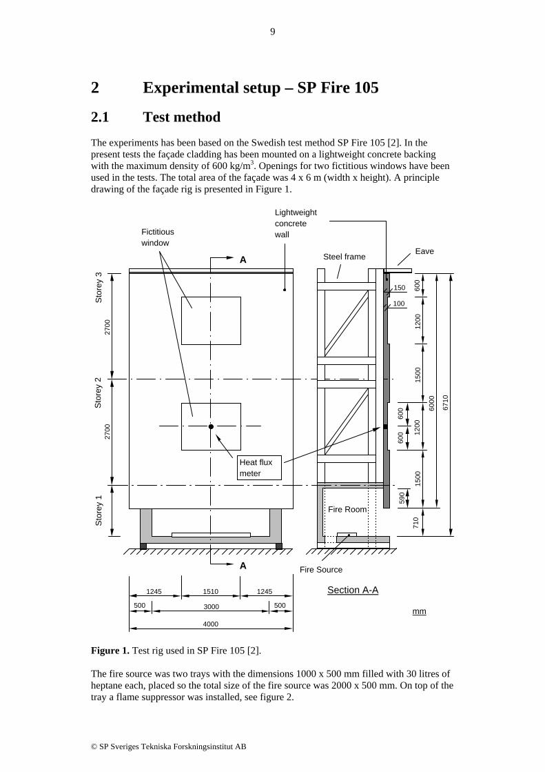
2.1 Test method The experiments has been based on the Swedish test method SP Fire 105 [2]. In the present tests the façade cladding has been mounted on a lightweight concrete backing with the maximum density of 600 kg/m3. Openings for two fictitious windows have been used in the tests. The total area of the façade was 4 x 6 m (width x height). A principle drawing of the façade rig is presented in Figure 1.
Figure 1. Test rig used in SP Fire 105 [2]. The fire source was two trays with the dimensions 1000 x 500 mm filled with 30 litres of heptane each, placed so the total size of the fire source was 2000 x 500 mm. On top of the tray a flame suppressor was installed, see figure 2.
Section A-A
6710
600
1200
1500
1200
1500
590
710
3000500 500
4000
2700
2700
100
150
1510 12451245
6000
600
600
A
A
Fire Room
Sto
rey
1S
tore
y 2
Sto
rey
3
Fire Source
mm
Eave
Fictitious window
Lightweight concrete wall
Heat flux meter
Steel frame

10
© SP Sveriges Tekniska Forskningsinstitut AB
Figure 2. Principle drawing of the fire source. There is an air intake directly behind the fuel source with the dimensions 3140 x 300 mm, centrally placed 50 mm from the back wall of the fire room, see figure 3.
Figure 3. Drawing of the fire room. The test rig was placed in the large fire hall at SP Fire Research in Borås, Sweden. The fuel trays as well as the heptane and water used were conditioned to the room temperature before any tests were performed. When filling the fuel into the trays first the right amount of heptane was filled. Thereafter water was added until the liquid surface reached the bottom surface of the flame suppressor.
100
2000
Tray of steel sheet
2000 x 500 x 100 mmWater
Heptane
Fire Source - Heptane
Water to raise the surface of the heptane fuel to the lower edge of the flame suppressor at the start of the fire test.
Flame suppressor
mm
20
Flame suppressor of perforated steel sheet, hole Ø=25 mm, center distance 40 mm.
mm

11
© SP Sveriges Tekniska Forskningsinstitut AB
Even when the test is carried out indoors, in the large test hall, the ventilation in the hall creates a wind. Some measurements have been done showing that the wind is in the order of 0.1-0.5 m/s, and in the direction parallel to the face of the façade rig, going from right to left side of the façade. 2.2 Test specimens Three different tests were carried out. The first test was made without any cladding on the lightweight concrete, i.e. an inert façade. In the second test a cladding of 24 mm thick plywood was mounted directly onto the lightweight concrete, i.e. no ventilation cavity behind the plywood. In the third test plywood was mounted with a ventilation cavity of approximately 20 mm between the lightweight concrete and the plywood. The plywood was bought at a local store for building materials, and it was a standard product for the Swedish market, with the dimensions 1200 x 2400 mm2. Samples were taken from the plywood for measurement of moisture content and density. These measurements were made approximately at the time of the tests. The plywood had a moisture content of 6.5 % and the density at that moisture content was determined to 489 kg/m3. The plywood was mounted on the whole front surface of the test rig, except at the fictitious windows. In order to get an air cavity behind the plywood for Test 3, strips of mineral wool, with density of 180 kg/m3, was used. These strips had a thickness of 20 mm (giving an air gap of 20 mm) and a width of approximately 30 mm. The mineral wool strips where mounted along all vertical edges of the plywood boards, i.e. they were not acting as fire stops in the vertical direction, although they were acting as fire stops in horizontal direction in the cavity. 2.3 Instrumentation and measurements The tests were performed with a lot of extra instrumentation in addition to the required instrumentation in accordance with SP Fire 105. Figure 4 shows the placement of different measuring devices on the surface of the test specimens. Devices C1-C19 are 0.5 mm wire diameter thermocouples, type K. The measuring point of the thermocouples were made with Quick-Tips, i.e. a small metal ring, diameter 3 mm and length 2 mm, that clamps the two wires together. The weight of a this size Quick-Tip is 0.1 g. In all tests the tip of the thermocouple (the Quick-Tip) was pressed into the surface of the exposed surface of the façade, i.e. the measurement represents approximately the surface temperature of the façade. In Test 3, plywood with a cavity, thermocouples were also mounted in the plywood surface on the cavity side at the same positions as on the front surface. Devices PT1-PT6 are conventional 100 x 100 mm plate thermometers, i.e. the same devices as used in fire resistance furnaces, see for example EN 1363-1 [6]. PT1-PT3 were placed on a distance 500 mm from the combustion chamber and pointing towards the fire, see also Figure 7. PT4-PT6 were mounted on the surface of the façade and pointing outwards. Plate thermometers have an time constant of between 1 and 2 minutes [7].

12
© SP Sveriges Tekniska Forskningsinstitut AB
Device HF1 is a Schmidt Boelter heat flux meter. The device was mounted flush with the surface of the fictitious window which is specified in SP Fire 105 [2].
Figure 4. Placement of measuring devices on the test specimens. PT1-PT3 are placed 500 mm outwards from the combustion chamber and directed towards the fire. In addition to these measurements temperature was also measured at a distance 100 and 200 mm from the façade with 0.5 mm type K thermocouples with a welded tip. These temperature measurements were performed at the same positions as thermocouples C2, C3, C6, C7, C13, C14, C17 and C18. The same positions were also used in Test 3 in the ventilation cavity where the thermocouples were mounted in the centre between the lightweight concrete and the plywood, that is 10 mm from the plywood surface. Furthermore, as specified in SP Fire 105, two 0.5 mm type K thermocouples with a welded tip were positioned 100 mm below the eave at the top of the façade rig (see figure 1), at a distance 100 mm and 400 mm from the façade surface, and at the centre line of the specimen.

13
© SP Sveriges Tekniska Forskningsinstitut AB

14
© SP Sveriges Tekniska Forskningsinstitut AB
3 Experimental setup – SBI A complimentary test was performed with the Single Burning Item (SBI) method, EN 13823 [8]. The SBI test is not a suitable method for testing façades due to several reasons, but it can be used for evaluation of the temperature measurements used for determination of fire spread on the façade surface. In the test two panels are used, one large wing with the dimensions 1.0 x 1.5 m2 (width x height), and a small wing with the dimensions 0.49 x 1.5 m2. In the bottom corner between the two panels a sand burner is used, which is burning with a constant effect of 30 kW. In the present study a total of 40 thermocouples were mounted on the surface of the test specimen, 20 thermocouples on the large wing, and 20 thermocouples on the small wing, see figure 5. The thermocouples were positioned at different heights, as shown in figure 5, and at different distance from the corner (100, 200, 300 and 400 mm).
Figure 5. Position of temperature measurements and type of hot tip of the thermocouples. The thermocouples were all of the same type, 0.5 mm diameter wire and of type K. The hot tip of the thermocouples, i.e. the tip where the two wires are connected, where prepared in four different ways.
15
© SP Sveriges Tekniska Forskningsinstitut AB
At a height of 400 mm and 700 mm above the floor level the tip was made with a Quick-Tip, i.e. a cylinder with diameter 3 mm and length 2 mm and a weight of 0.1 g, is clamped around the two wires. The Quick-Tip is then pressed into the surface of the specimen so it will be flush with the surface. This is a robust method which enables the measuring point to be pressed into the surface. Although, the thermal inertia is higher due to the mass of the Quick-Tip, compared with welded wires, and thus the response time is slightly longer for this type of thermocouple. At the height 500 mm and 900 mm the thermocouple was welded to a copper disc with diameter 10 mm, i.e. the same type used for measurement of surface temperature in fire resistance tests in accordance with EN 1363-1 [6], but without using the insulation pad. The thermocouple and the copper disc were attached to the surface by clamping and tape. With this type of thermocouple the measured temperature is in principle averaged over a larger area, i.e. the area of the highly conductive copper disc. Although, the copper disc protects the underlying material for radiation from the fire, but it may be possible to detect eventual fire spread on the surface around the copper disc. At the height 600 mm and 1000 mm a welded tip of the thermocouples were used. The wire was attached to the test specimen by clamping and tape. This type of thermocouple tip has the lowest thermal inertia and thus it gives the fastest response time in this study. Although, it is more difficult to mount it flush to the surface for estimations of surface temperature. At the height 800 mm the thermocouples were welded to a horizontal steel wire, i.e. all thermocouples were fixed to the same steel wire. The steel wire was clamped to the test specimen. The idea with this type of mounting was mainly to have a method for easy mounting of thermocouples.

16
© SP Sveriges Tekniska Forskningsinstitut AB
4 Test results 4.1 General observations Three tests were performed indoors in the large test hall at SP. In Test 1 the backing material of the façade rig consisted of lightweight concrete and was used without any further cladding. In Test 2 the lightweight concrete was covered with the plywood cladding. In Test 3 the same type of plywood cladding was used, with a 20 mm air gap, cavity, between the lightweight concrete and the plywood. The lightweight concrete on the façade rig, i.e. the inert façade, was in equilibrium with approximately 50 % relative humidity, and had a density of 550 kg/m3. The moisture content and the density of the plywood was measured at the time of testing. The moisture content was 6.5 % and the density at that moisture content was determined to 489 kg/m3. Table 1 gives some general information regarding the three tests made. Table 1. General information on the tests Test 1 Test 2 Test 3 Test date 2015-11-26
(morning) 2015-11-26 (afternoon)
2015-11-27 (morning)
Initial air temperature 18.8 °C 17.3 °C 18.0 °C Initial relative humidity 38 % 40 % 49 % Temperature of heptane and water 19.2 °C 16.2 °C 15.9 °C In tables 2-4 the visual observations made during the test are presented. It shall be noted that the visual observations represent the observations made during the tests, and that the actual issue observed may have occurred earlier than the noted time. Table 2. Visual observations during Test 1 – inert façade. Time min:s Observations
00:00 The fire source of heptane is ignited. The test starts. 03:30 Smoke emerges out from the fire room. 04:00 Dark smoke emerges out from the fire room. 04:10 Flames and dark smoke emerge out from the fire room. 04:35 Some flames reach up to the lower edge of the lower window opening. 05:30 Some flames reach up to the upper edge of the lower window opening. 07:00 Flames reach half the height of the façade. 08:20 Flames reach up to the lower edge of the upper window opening. 10:30 Flames reach half the height of the façade. 12:50 Some flames reach up to the lower edge of the upper window opening. 14:00 Some flames reach just above the lower edge of the upper window opening. 15:30 Some flames reach up to the lower edge of the upper window opening. 16:50 The flames cease. 17:00 Flames reach just out from the fire room. Dark smoke comes out from the fire room. 18:00 The test terminates. The fire source has become extinct. The test specimen is
extinguished with water.

17
© SP Sveriges Tekniska Forskningsinstitut AB
Table 3. Visual observations during Test 2 – plywood without cavity. Time min:s Observations
00:00 The fire source of heptane is ignited. The test starts. 03:00 Smoke emerges out from the fire room. 04:10 Flames and dark smoke emerge out from the fire room. 04:30 Flames reach up to the lower edge of the lower window opening. 05:00 Flames reach above the upper edge of the lower window opening. 05:25 Flames reach the eave. 05:50 It burns along the upper edge of the lower window opening. The plywood panel
between the window openings glows. 07:00 It burns in the lower left corner of the upper window opening. 09:00 Flames reach up to the lower edge of the upper window opening. 10:00 Flames cease and reach half the height of the façade. 11:45 Flames along the right side of the façade reach up to the upper edge of the upper
window opening. 12:15 Flames reach the eave. It burns in the lower right corner of the upper window
opening. 13:00 It burns along the left side of the upper window opening. 13:45 It burns in the plywood panel on the right side between the window openings. 14:30 Flames along the left side of the façade reach up to the lower edge of the upper
window opening. 15:30 Flames reach half the height of the façade. Small glowing pieces from the plywood
fall down in front of the façade. 16:00 Flames reach up to the upper edge of the lower window opening. 16:15 Flames reach up to the lower edge of the lower window opening. 16:30 Flames reach just out from the fire room. 17:15 The test terminates. The fire source has become extinct. The test specimen is
extinguished with water.

18
© SP Sveriges Tekniska Forskningsinstitut AB
Table 4. Visual observations during Test 3 – plywood with cavity. Time min:s Observations
00:00 The fire source of heptane is ignited. The test starts. 03:00-04:00
Smoke emerges out from the fire room.
04:25 Flames and dark smoke emerge out from the fire room. 05:00 Flames reach up to the lower edge of the lower window opening. 05:45 Flames reach up to the upper edge of the upper window opening. 06:00 It burns along the upper edge of the lower window opening 06:30 It burns along the lower edge of the upper window opening along the left side. 07:30 Flames reach the eave. 09:40 It burns along the upper edge of the lower window opening and along the lower edge
of the upper window opening. 10:30 Flames reach almost to the eave. 11:00 It burns along the left side of the upper window opening. 11:20 It burns in the upper left corner of the upper window opening. 11:40 It burns along the upper edge of the upper window opening. 12:10 The lower left panel is not attached to the wall on the right side. 12:40 Flames reach the eave. 13:00 Part from the lower left panel falls down in front of the façade. 13:40 Some small burning pieces on the floor in front of the façade. 14:00 Flames reach above the eave. 14:20 It glows in the air gap by the eave. 16:00 Flames above the eave. 17:00 Flames cease. Dark smoke. 17:45 The test terminates. The fire source has become extinct. The test specimen is
extinguished with water. Photographs taken during the tests are presented in figure 6. It can be noted that visual observations on the flame spread can be difficult due the extensive smoke production during the tests.

19
© SP Sveriges Tekniska Forskningsinstitut AB
Test 1. Time: 09:00 min:s
Test 2. Time: 09:00 min:s
Test 3. Time: 07:00 min:s
Test 1. Time: 12:00 min:s
Test 2. Time: 11:00 min:s
Test 3. Time: 12:00 min:s
Test 1. Time: 15:00 min:s
Test 2. Time: 14:00 min:s
Test 3. Time: 13:00 min:s
Figure 6. Photos taken during the test, Test 1 to the left, Test 2 in the centre, and Test 3 to the right.

20
© SP Sveriges Tekniska Forskningsinstitut AB
4.2 Fire source The temperature from the fire source was measured by three plate thermometers placed 0.5 m from the opening of the combustion chamber (measured from the inner side of the lightweight concrete). The plate thermometers were pointing towards the fire, and would thus measure the heat exposure mainly from the fire source, see figures 4 and 7.
Figure 7. Position of plate thermometers in front of the combustion chamber. The measured temperatures in front of the combustion chamber from each test are presented in figures 8 – 10. It is clearly shown in the growth phase in the figures that the flames from the combustion chamber is more intense on the left side compared with the right side in all tests, which also was noted visually during the tests. During the growth phase the buoyancy force in the plume is apparently not strong enough to create a vertical flow speed high enough to counteract the side winds in the laboratory. It can also be noted that it is generally hotter in the centre, but there are shorter periods during the tests where it is hotter on the left side.
1300
710
590
100
Fire source
Air intake
PT (Plate thermometer)

21
© SP Sveriges Tekniska Forskningsinstitut AB
Figure 8. Temperature measured with plate thermometers 0.5 m from the combustion chamber in Test 1, inert façade. PT1 on left side, PT2 at the centre, and PT3 on the right side.
Figure 9. Temperature measured with plate thermometers 0.5 m from the combustion chamber in Test 2, plywood façade without ventilation gap. PT1 on left side, PT2 at the centre, and PT3 on the right side.
0
100
200
300
400
500
600
700
800
0 5 10 15 20
Tem
pera
ture
(°C)
Time (minutes)
Test 1 - inert facade
PT1
PT2
PT3
0
100
200
300
400
500
600
700
800
0 5 10 15 20
Tem
pera
ture
(°C)
Time (minutes)
Test 2 - plywood without cavity
PT1
PT2
PT3

22
© SP Sveriges Tekniska Forskningsinstitut AB
Figure 10. Temperature measured with plate thermometers 0.5 m from the combustion chamber in Test 3, plywood façade with a ventilation gap. PT1 on left side, PT2 at the centre, and PT3 on the right side. A mean temperature from the three plate thermometers in each test is shown in figure 11. The start of the third test was slower compared to the two first tests. Therefore a small time compensation of 30 seconds have been subtracted for the third test. The results show that the initial phase of the fire is very similar in all tests, and the duration of the tests is the same. Although there is a difference in the interval from 5 minutes up to 15 minutes, where the façade with plywood cladding had both the highest and lowest temperatures. The plywood façade with cavity gap showed the lowest temperatures in front of the combustion chamber.
0
100
200
300
400
500
600
700
800
0 5 10 15 20
Tem
pera
ture
(°C)
Time (minutes)
Test 3 - plywood with cavity
PT1
PT2
PT3

23
© SP Sveriges Tekniska Forskningsinstitut AB
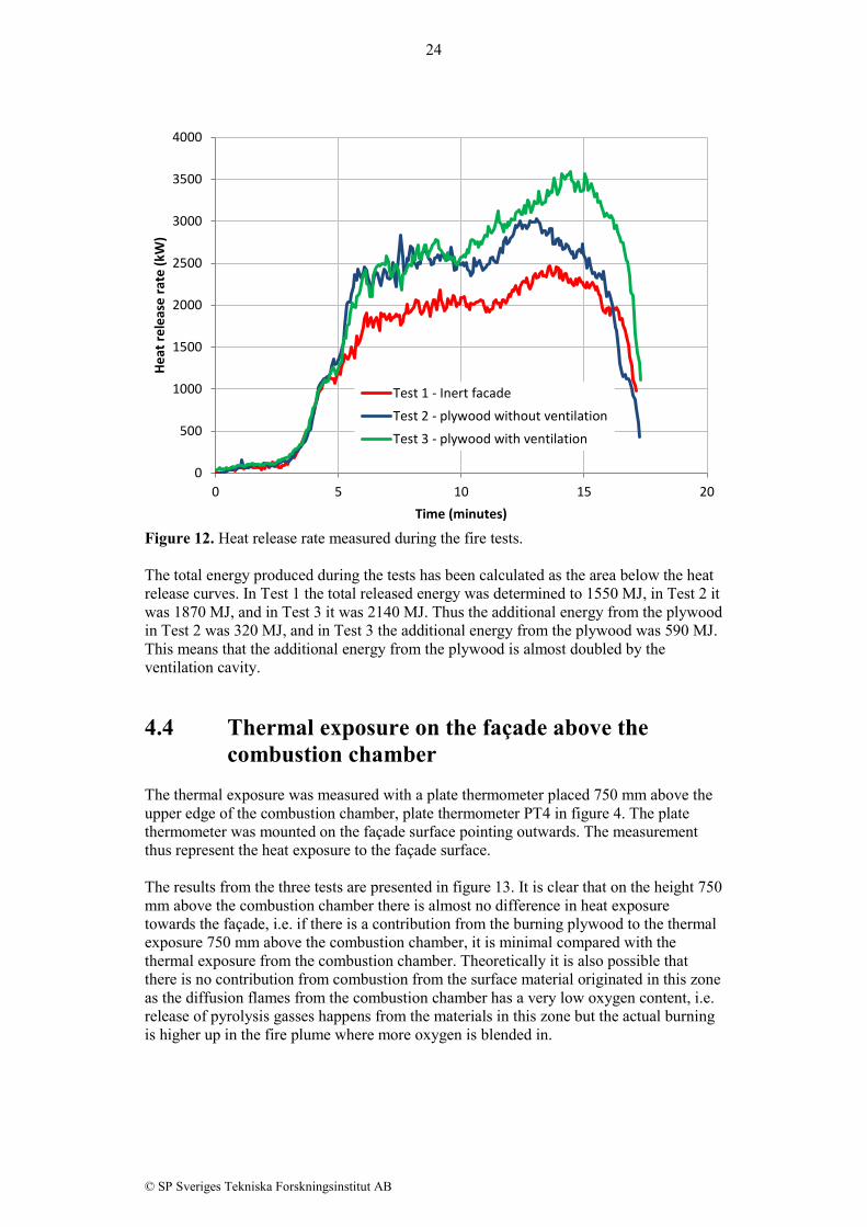
Figure 11. Mean temperature measured with plate thermometers 0.5 m from the combustion chamber. 4.3 Heat release rate The heat release rate was measured by collecting the exhaust gases in a hood above the façade test rig [9]. The measured heat release rate is presented in figure 12. It can be noted that the initial phase of the test, up to 5 minutes, is similar in all tests, i.e. no difference between a combustible surface and an inert façade. From 5 minutes up to 10 minutes, the behaviour of the two tests with plywood is similar, i.e. the ventilation cavity does not influence on the heat release rate. The heat release rate increases with approximately 500 kW for the combustible façades compared with the inert one. After 10 minutes into the tests, the heat release rate start to increase again, and here a difference shows up between the unventilated plywood façade and the one with a ventilation cavity. After 15 minutes the peak is reached in Test 3, and the heat release rate is approximately 500 kW higher compared to the peak value obtained with plywood façade without ventilation, and more than 1000 kW compared to the inert façade.
0
100
200
300
400
500
600
700
800
0 5 10 15 20
Tem
pera
ture
(°C)
Time (minutes)
Mean temperature from each test
Test 1 - inert facade
Test 2 - plywood without ventilation
Test 3 - plywood with ventilation
24
© SP Sveriges Tekniska Forskningsinstitut AB
Figure 12. Heat release rate measured during the fire tests. The total energy produced during the tests has been calculated as the area below the heat release curves. In Test 1 the total released energy was determined to 1550 MJ, in Test 2 it was 1870 MJ, and in Test 3 it was 2140 MJ. Thus the additional energy from the plywood in Test 2 was 320 MJ, and in Test 3 the additional energy from the plywood was 590 MJ. This means that the additional energy from the plywood is almost doubled by the ventilation cavity. 4.4 Thermal exposure on the façade above the
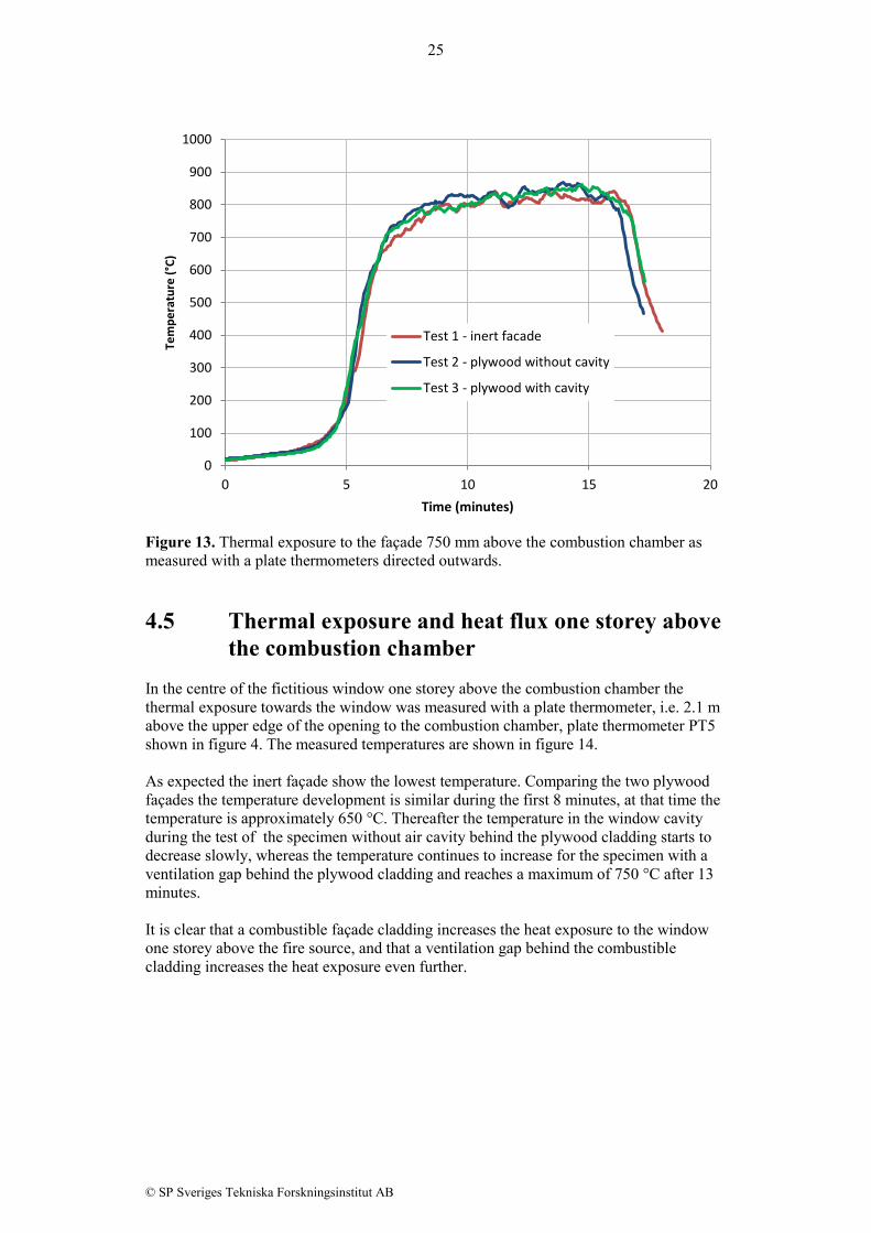
combustion chamber The thermal exposure was measured with a plate thermometer placed 750 mm above the upper edge of the combustion chamber, plate thermometer PT4 in figure 4. The plate thermometer was mounted on the façade surface pointing outwards. The measurement thus represent the heat exposure to the façade surface. The results from the three tests are presented in figure 13. It is clear that on the height 750 mm above the combustion chamber there is almost no difference in heat exposure towards the façade, i.e. if there is a contribution from the burning plywood to the thermal exposure 750 mm above the combustion chamber, it is minimal compared with the thermal exposure from the combustion chamber. Theoretically it is also possible that there is no contribution from combustion from the surface material originated in this zone as the diffusion flames from the combustion chamber has a very low oxygen content, i.e. release of pyrolysis gasses happens from the materials in this zone but the actual burning is higher up in the fire plume where more oxygen is blended in.
0
500
1000
1500
2000
2500
3000
3500
4000
0 5 10 15 20
Heat
rele
ase
rate
(kW
)
Time (minutes)
Test 1 - Inert facadeTest 2 - plywood without ventilationTest 3 - plywood with ventilation
25
© SP Sveriges Tekniska Forskningsinstitut AB
Figure 13. Thermal exposure to the façade 750 mm above the combustion chamber as measured with a plate thermometers directed outwards. 4.5 Thermal exposure and heat flux one storey above
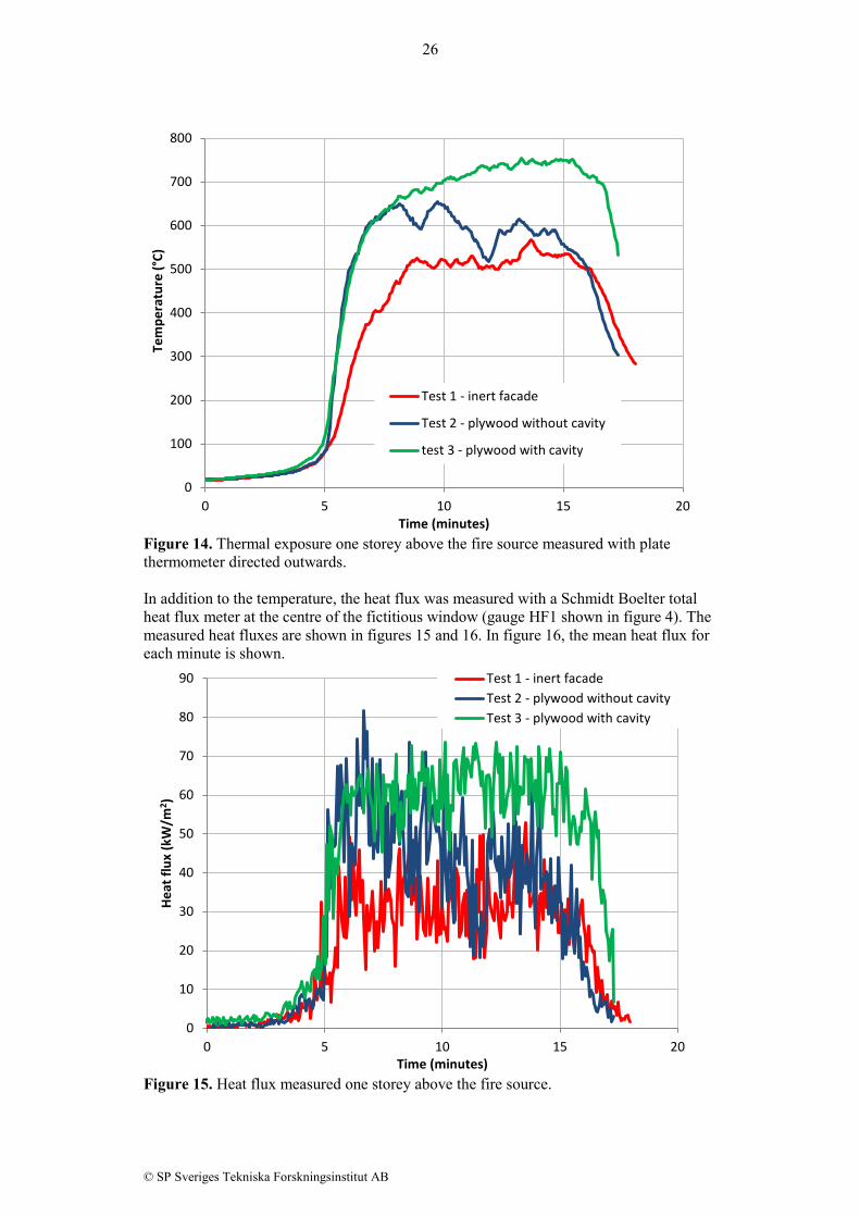
the combustion chamber In the centre of the fictitious window one storey above the combustion chamber the thermal exposure towards the window was measured with a plate thermometer, i.e. 2.1 m above the upper edge of the opening to the combustion chamber, plate thermometer PT5 shown in figure 4. The measured temperatures are shown in figure 14. As expected the inert façade show the lowest temperature. Comparing the two plywood façades the temperature development is similar during the first 8 minutes, at that time the temperature is approximately 650 °C. Thereafter the temperature in the window cavity during the test of the specimen without air cavity behind the plywood cladding starts to decrease slowly, whereas the temperature continues to increase for the specimen with a ventilation gap behind the plywood cladding and reaches a maximum of 750 °C after 13 minutes. It is clear that a combustible façade cladding increases the heat exposure to the window one storey above the fire source, and that a ventilation gap behind the combustible cladding increases the heat exposure even further.
0
100
200
300
400
500
600
700
800
900
1000
0 5 10 15 20
Tem
pera
ture
(°C)
Time (minutes)
Test 1 - inert facade
Test 2 - plywood without cavity
Test 3 - plywood with cavity
26
© SP Sveriges Tekniska Forskningsinstitut AB
Figure 14. Thermal exposure one storey above the fire source measured with plate thermometer directed outwards. In addition to the temperature, the heat flux was measured with a Schmidt Boelter total heat flux meter at the centre of the fictitious window (gauge HF1 shown in figure 4). The measured heat fluxes are shown in figures 15 and 16. In figure 16, the mean heat flux for each minute is shown.
Figure 15. Heat flux measured one storey above the fire source.
0
100
200
300
400
500
600
700
800
0 5 10 15 20
Tem
pera
ture
(°C)
Time (minutes)
Test 1 - inert facade
Test 2 - plywood without cavity
test 3 - plywood with cavity
0
10
20
30
40
50
60
70
80
90
0 5 10 15 20
Heat
flux
(kW
/m2 )
Time (minutes)
Test 1 - inert facadeTest 2 - plywood without cavityTest 3 - plywood with cavity

27
© SP Sveriges Tekniska Forskningsinstitut AB
Figure 16. Heat flux (mean valued over one minute) measured one storey above the fire source. 4.6 Thermal exposure two storeys above the
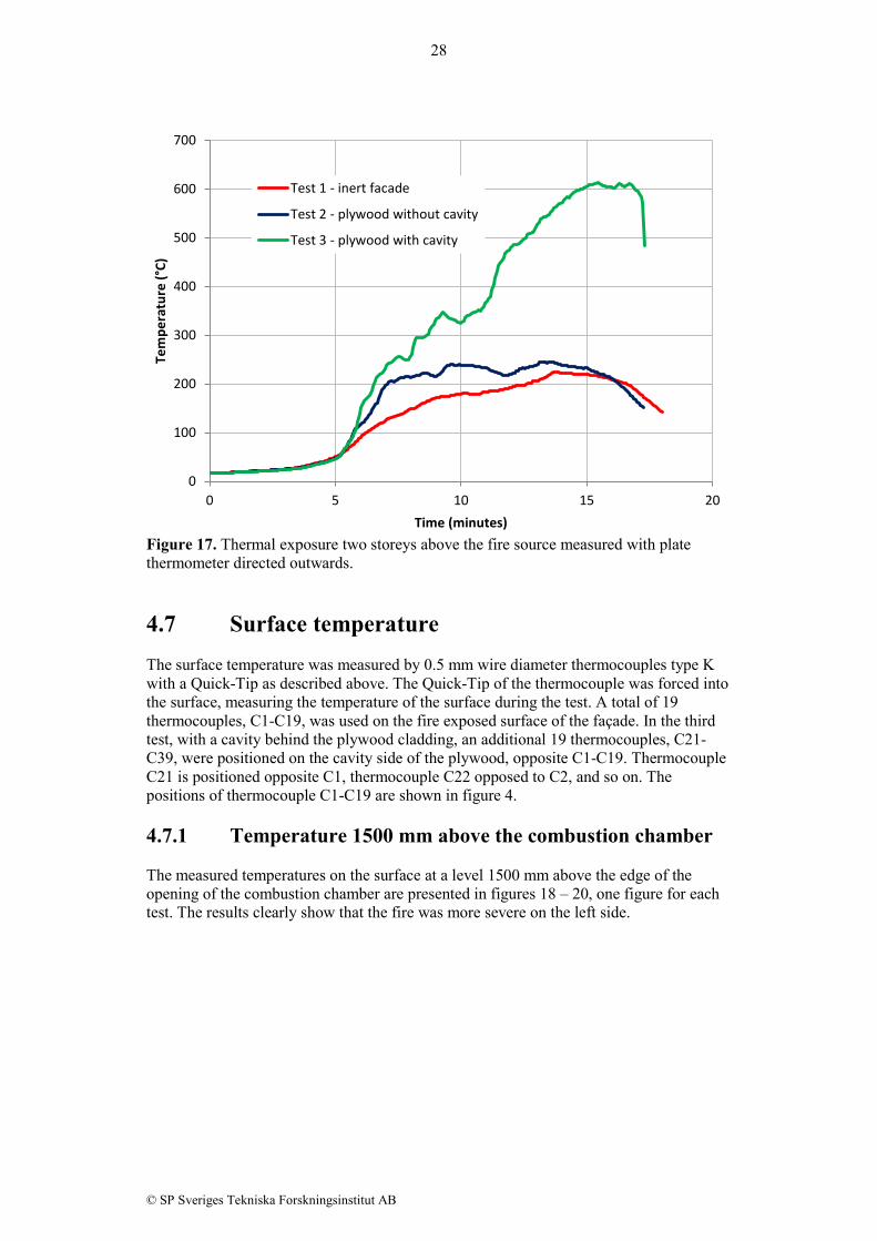
combustion chamber In the centre of the fictitious window two storeys above the combustion chamber the temperature exposure towards the window was measured with a plate thermometer, i.e. 4,8 m above the upper edge of the opening to the combustion chamber, plate thermometer PT6 shown in figure 4. The measured temperatures are shown in figure 17. At this height there is a clear difference between the tests. The ventilation cavity used in Test 3 has a significant effect on the heat exposure to the fictitious window two stories above the fire room. After 15 minutes the temperature is over 600 °C in Test 3. When comparing Test 1 and Test 2, i.e. the inert façade and the plywood cladding without cavity, the difference between these tests is relatively small. The façade with plywood cladding have a faster temperature rise between 5 and 7 minutes, after which the temperature stabilizes between 200-250 °C. The inert façade has a slower temperature rise, but it reaches almost as high in temperature.
0
10
20
30
40
50
60
70
80
0 5 10 15 20
Heat
flux
(kW
/m2 )
Time (minutes)
Test 1 - inert facadeTest 2 - plywood without cavityTest 3 - plywood with cavity
28
© SP Sveriges Tekniska Forskningsinstitut AB
Figure 17. Thermal exposure two storeys above the fire source measured with plate thermometer directed outwards. 4.7 Surface temperature The surface temperature was measured by 0.5 mm wire diameter thermocouples type K with a Quick-Tip as described above. The Quick-Tip of the thermocouple was forced into the surface, measuring the temperature of the surface during the test. A total of 19 thermocouples, C1-C19, was used on the fire exposed surface of the façade. In the third test, with a cavity behind the plywood cladding, an additional 19 thermocouples, C21-C39, were positioned on the cavity side of the plywood, opposite C1-C19. Thermocouple C21 is positioned opposite C1, thermocouple C22 opposed to C2, and so on. The positions of thermocouple C1-C19 are shown in figure 4. 4.7.1 Temperature 1500 mm above the combustion chamber The measured temperatures on the surface at a level 1500 mm above the edge of the opening of the combustion chamber are presented in figures 18 – 20, one figure for each test. The results clearly show that the fire was more severe on the left side.
0
100
200
300
400
500
600
700
0 5 10 15 20
Tem
pera
ture
(°C)
Time (minutes)
Test 1 - inert facade
Test 2 - plywood without cavity
Test 3 - plywood with cavity

29
© SP Sveriges Tekniska Forskningsinstitut AB
Figure 18. Temperature on the surface during Test 1, 1500 mm above the combustion chamber.
Figure 19. Temperature on the surface during Test 2, 1500 mm above the combustion chamber.
0
100
200
300
400
500
600
700
0 5 10 15 20
Tem
pera
ture
(°C)
Time (minutes)
Test 1 - inert facade
C1
C2
C3
C4
0
100
200
300
400
500
600
700
800
900
0 5 10 15 20
Tem
pera
ture
(°C)
Time (minutes)
Test 2 - plywood without cavity
C1
C2
C3
C4

30
© SP Sveriges Tekniska Forskningsinstitut AB
Figure 20. Temperature on the surface during Test 3, 1500 mm above the combustion chamber.
Figure 21. Temperature on the surface of the plywood in the cavity 1500 mm above the combustion chamber. The temperature was measured on the surface of the plywood in the cavity during Test 3. The results from these measurements are shown in figure 21 above. Unlike the temperatures measured on the outward surface, which decreases at the end of the tests, the temperature increases rapidly.
0
100
200
300
400
500
600
700
800
900
0 5 10 15 20
Tem
pera
ture
(°C)
Time (minutes)
Test 3 - plywood with cavity
C1
C2
C3
C4
0
50
100
150
200
250
300
350
400
450
0 5 10 15 20
Tem
pera
ture
(°C)
Time (minutes)
Test 3 - plywood with cavity Surface temperature in the cavity
C21
C22
C23
C24
31
© SP Sveriges Tekniska Forskningsinstitut AB
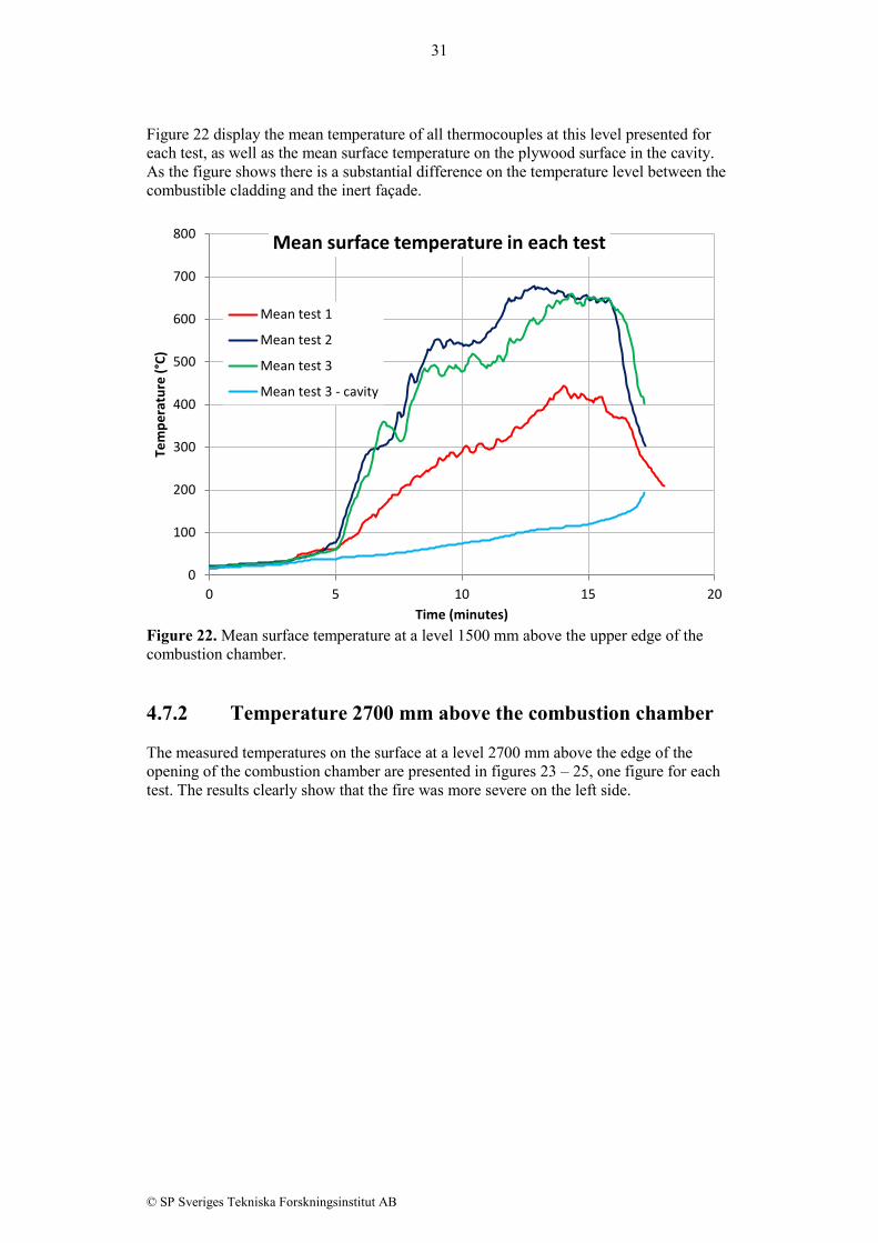
Figure 22 display the mean temperature of all thermocouples at this level presented for each test, as well as the mean surface temperature on the plywood surface in the cavity. As the figure shows there is a substantial difference on the temperature level between the combustible cladding and the inert façade.
Figure 22. Mean surface temperature at a level 1500 mm above the upper edge of the combustion chamber. 4.7.2 Temperature 2700 mm above the combustion chamber The measured temperatures on the surface at a level 2700 mm above the edge of the opening of the combustion chamber are presented in figures 23 – 25, one figure for each test. The results clearly show that the fire was more severe on the left side.
0
100
200
300
400
500
600
700
800
0 5 10 15 20
Tem
pera
ture
(°C)
Time (minutes)
Mean surface temperature in each test
Mean test 1
Mean test 2
Mean test 3
Mean test 3 - cavity

32
© SP Sveriges Tekniska Forskningsinstitut AB
Figure 23. Temperature on the surface during Test 1, 2700 mm above the combustion chamber.
Figure 24. Temperature on the surface during Test 2, 2700 mm above the combustion chamber.
0
50
100
150
200
250
300
350
400
450
0 5 10 15 20
Tem
pera
ture
(°C)
Time (minutes)
Test 1 - inert facade
C5
C6
C7
C8
0
100
200
300
400
500
600
700
800
0 5 10 15 20
Tem
pera
ture
(°C)
Time (minutes)
Test 2 - plywood without cavity
C5
C6
C7
C8

33
© SP Sveriges Tekniska Forskningsinstitut AB
Figure 25. Temperature on the surface during Test 3, 2700 mm above the combustion chamber. The temperature was measured on the surface of the plywood in the cavity during Test 3. The results from these measurements are shown in figure 26. Unlike the temperatures measured on the outward surface, which decreases at the end of the tests, the temperature increases rapidly.
Figure 26. Temperature on the surface of the plywood in the cavity 2700 mm above the combustion chamber.
0
100
200
300
400
500
600
700
800
0 5 10 15 20
Tem
pera
ture
(°C)
Time (minutes)
Test 3 - plywood with cavity
C5
C6
C7
C8
0
20
40
60
80
100
120
140
160
180
0 5 10 15 20
Tem
pera
ture
(°C)
Time (minutes)
Test 3 - plywood with cavity Surface temperature of plywood in cavity
C25
C26
C27
C28

34
© SP Sveriges Tekniska Forskningsinstitut AB
In figure 27 the mean temperature of all thermocouples at this level presented for each test, as well as the mean surface temperature on the plywood surface in the cavity. As the figure shows there is a substantial difference on the temperature level between the combustible cladding and the inert façade.
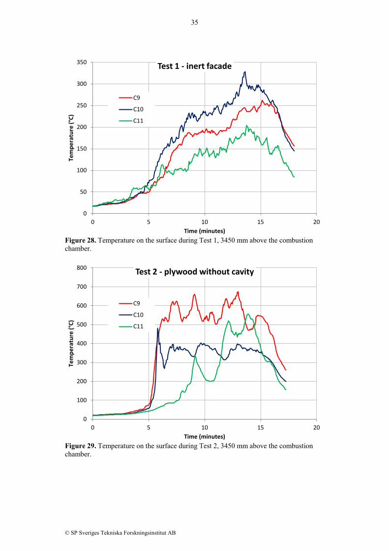
Figure 27. Mean surface temperature at a level 2700 mm above the upper edge of the combustion chamber. 4.7.3 Temperature 3450 mm above the combustion chamber The measured temperatures on the surface at a level 3450 mm above the edge of the opening of the combustion chamber are presented in figures 28 – 30, one figure for each test. The results clearly show that the fire was more severe on the left side.
0
100
200
300
400
500
600
700
0 5 10 15 20
Tem
pera
ture
(°C)
Time (minutes)
Mean surface temperature in each test
Mean test 1
Mean test 2
Mean test 3
Mean test 3 - cavity
35
© SP Sveriges Tekniska Forskningsinstitut AB
Figure 28. Temperature on the surface during Test 1, 3450 mm above the combustion chamber.
Figure 29. Temperature on the surface during Test 2, 3450 mm above the combustion chamber.
0
50
100
150
200
250
300
350
0 5 10 15 20
Tem
pera
ture
(°C)
Time (minutes)
Test 1 - inert facade
C9
C10
C11
0
100
200
300
400
500
600
700
800
0 5 10 15 20
Tem
pera
ture
(°C)
Time (minutes)
Test 2 - plywood without cavity
C9
C10
C11

36
© SP Sveriges Tekniska Forskningsinstitut AB
Figure 30. Temperature on the surface during Test 3, 3450 mm above the combustion chamber. The temperature was measured on the surface of the plywood in the cavity during Test 3. The results from these measurements are shown in figure 31. At this level the temperature in the surface of the plywood in the cavity do not show the same increasing temperatures at the end of the test.
Figure 31. Temperature on the surface of the plywood in the cavity 3450 mm above the combustion chamber.
0
100
200
300
400
500
600
700
800
0 5 10 15 20
Tem
pera
ture
(°C)
Time (minutes)
Test 3 - plywood with cavity
C9
C10
C11
0
100
200
300
400
500
600
700
800
900
0 5 10 15 20
Tem
pera
ture
(°C)
Time (minutes)
Test 3 - plywood with cavity Surface temperature of plywood in cavity
C29
C30
C31

37
© SP Sveriges Tekniska Forskningsinstitut AB
In figure 32 the mean temperature of all thermocouples at this level is presented for each test, as well as the mean surface temperature on the plywood surface in the cavity. As the figure shows there is a substantial difference on the temperature level between the combustible cladding and the inert façade. It can also be noted that the mean surface temperature in Test 3 is approximately the same on the outer surface as on the surface in the cavity at the end of the test.
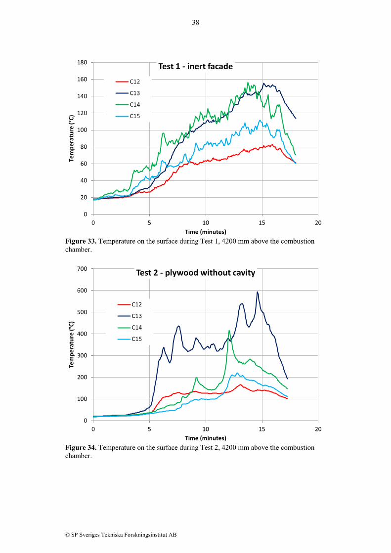
Figure 32. Mean surface temperature at a level 3450 mm above the upper edge of the combustion chamber. 4.7.4 Temperature 4200 mm above the combustion chamber The measured temperatures on the surface at a level 4200 mm above the edge of the opening of the combustion chamber are presented in figures 33 – 35, one figure for each test. The results clearly show that the fire was more severe on the left side in Test 2 and Test 3. In Test 1, however, the temperature readings show a more centrally exposure at this level.
0
100
200
300
400
500
600
700
800
0 5 10 15 20
Tem
pera
ture
(°C)
Time (minutes)
Mean surface temperature in each test
Mean test 1
Mean test 2
Mean test 3
Mean test 3 - cavity
38
© SP Sveriges Tekniska Forskningsinstitut AB
Figure 33. Temperature on the surface during Test 1, 4200 mm above the combustion chamber.
Figure 34. Temperature on the surface during Test 2, 4200 mm above the combustion chamber.
0
20
40
60
80
100
120
140
160
180
0 5 10 15 20
Tem
pera
ture
(°C)
Time (minutes)
Test 1 - inert facade C12
C13
C14
C15
0
100
200
300
400
500
600
700
0 5 10 15 20
Tem
pera
ture
(°C)
Time (minutes)
Test 2 - plywood without cavity
C12
C13
C14
C15

39
© SP Sveriges Tekniska Forskningsinstitut AB
Figure 35. Temperature on the surface during Test 3, 4200 mm above the combustion chamber. The temperature was measured on the surface of the plywood in the cavity during Test 3. The results from these measurements are shown in figure 36. At this level the temperature in the surface of the plywood in the cavity is continuously increasing, and accelerating at the end of the test.
Figure 36. Temperature on the surface of the plywood in the cavity 4200 mm above the combustion chamber.
0
100
200
300
400
500
600
700
0 5 10 15 20
Tem
pera
ture
(°C)
Time (minutes)
Test 3 - plywood with cavity
C12
C13
C14
C15
0
20
40
60
80
100
120
0 5 10 15 20
Tem
pera
ture
(°C)
Time (minutes)
Test 3 - plywood with cavity Surface temperature of plywood in cavity
C32
C33
C34
C35

40
© SP Sveriges Tekniska Forskningsinstitut AB
In figure 37 the mean temperature of all thermocouples at this level is presented for each test, as well as the mean surface temperature on the plywood surface in the cavity. As the figure shows there is a substantial difference on the temperature level between the combustible cladding and the inert façade.
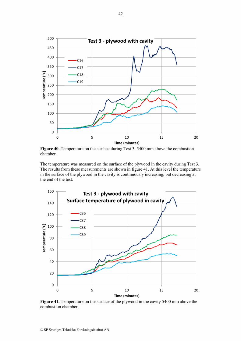
Figure 37. Mean surface temperature at a level 4200 mm above the upper edge of the combustion chamber. 4.7.5 Temperature 5400 mm above the combustion chamber The measured temperatures on the surface at a level 5400 mm above the edge of the opening of the combustion chamber are presented in figures 38 – 40, one figure for each test. The results clearly show that the fire was more severe on the left side of the specimen in all three tests.
0
50
100
150
200
250
300
350
400
0 5 10 15 20
Tem
pera
ture
(°C)
Time (minutes)
Mean surface temperature in each test
Mean test 1
Mean test 2
Mean test 3
Mean test 3 - cavity

41
© SP Sveriges Tekniska Forskningsinstitut AB
Figure 38. Temperature on the surface during Test 1, 5400 mm above the combustion chamber.
Figure 39. Temperature on the surface during Test 2, 5400 mm above the combustion chamber.
0
20
40
60
80
100
120
140
160
180
0 5 10 15 20
Tem
pera
ture
(°C)
Time (minutes)
Test 1 - inert facade C16
C17
C18
C19
0
50
100
150
200
250
300
350
400
0 5 10 15 20
Tem
pera
ture
(°C)
Time (minutes)
Test 2 - plywood without cavity
C16
C17
C18
C19
42
© SP Sveriges Tekniska Forskningsinstitut AB
Figure 40. Temperature on the surface during Test 3, 5400 mm above the combustion chamber. The temperature was measured on the surface of the plywood in the cavity during Test 3. The results from these measurements are shown in figure 41. At this level the temperature in the surface of the plywood in the cavity is continuously increasing, but decreasing at the end of the test.
Figure 41. Temperature on the surface of the plywood in the cavity 5400 mm above the combustion chamber.
0
50
100
150
200
250
300
350
400
450
500
0 5 10 15 20
Tem
pera
ture
(°C)
Time (minutes)
Test 3 - plywood with cavity
C16
C17
C18
C19
0
20
40
60
80
100
120
140
160
0 5 10 15 20
Tem
pera
ture
(°C)
Time (minutes)
Test 3 - plywood with cavity Surface temperature of plywood in cavity
C36
C37
C38
C39
43
© SP Sveriges Tekniska Forskningsinstitut AB
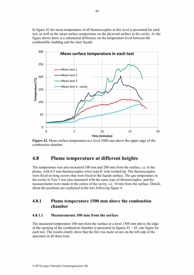
In figure 42 the mean temperature of all thermocouples at this level is presented for each test, as well as the mean surface temperature on the plywood surface in the cavity. As the figure shows there is a substantial difference on the temperature level between the combustible cladding and the inert façade.
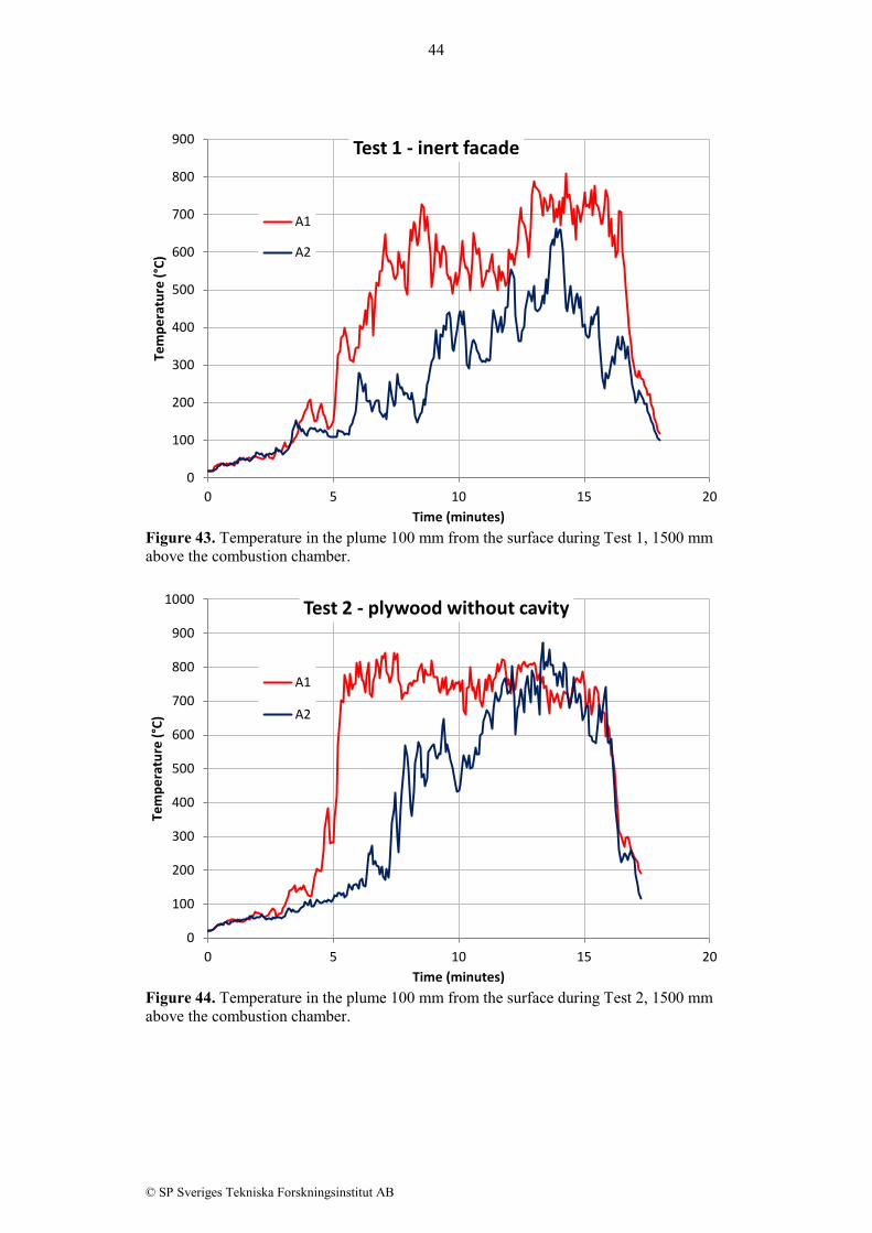
Figure 42. Mean surface temperature at a level 5400 mm above the upper edge of the combustion chamber. 4.8 Plume temperature at different heights The temperature was also measured 100 mm and 200 mm from the surface, i.e. in the plume, with 0.5 mm thermocouples wires type K with welded tip. The thermocouples were fixed on long screws that were fixed to the façade surface. The gas temperature in the cavity in Test 3 was also measured with the same type of thermocouples, and the measurements were made in the centre of the cavity, i.e. 10 mm from the surface. Details about the positions are explained in the text following figure 4. 4.8.1 Plume temperature 1500 mm above the combustion
chamber 4.8.1.1 Measurements 100 mm from the surface The measured temperature 100 mm from the surface at a level 1500 mm above the edge of the opening of the combustion chamber is presented in figures 43 – 45, one figure for each test. The results clearly show that the fire was more severe on the left side of the specimen in all three tests.
0
50
100
150
200
250
300
0 5 10 15 20
Tem
pera
ture
(°C)
Time (minutes)
Mean surface temperature in each test
Mean test 1
Mean test 2
Mean test 3
Mean test 3 - cavity
44
© SP Sveriges Tekniska Forskningsinstitut AB
Figure 43. Temperature in the plume 100 mm from the surface during Test 1, 1500 mm above the combustion chamber.
Figure 44. Temperature in the plume 100 mm from the surface during Test 2, 1500 mm above the combustion chamber.
0
100
200
300
400
500
600
700
800
900
0 5 10 15 20
Tem
pera
ture
(°C)
Time (minutes)
Test 1 - inert facade
A1
A2
0
100
200
300
400
500
600
700
800
900
1000
0 5 10 15 20
Tem
pera
ture
(°C)
Time (minutes)
Test 2 - plywood without cavity
A1
A2
45
© SP Sveriges Tekniska Forskningsinstitut AB
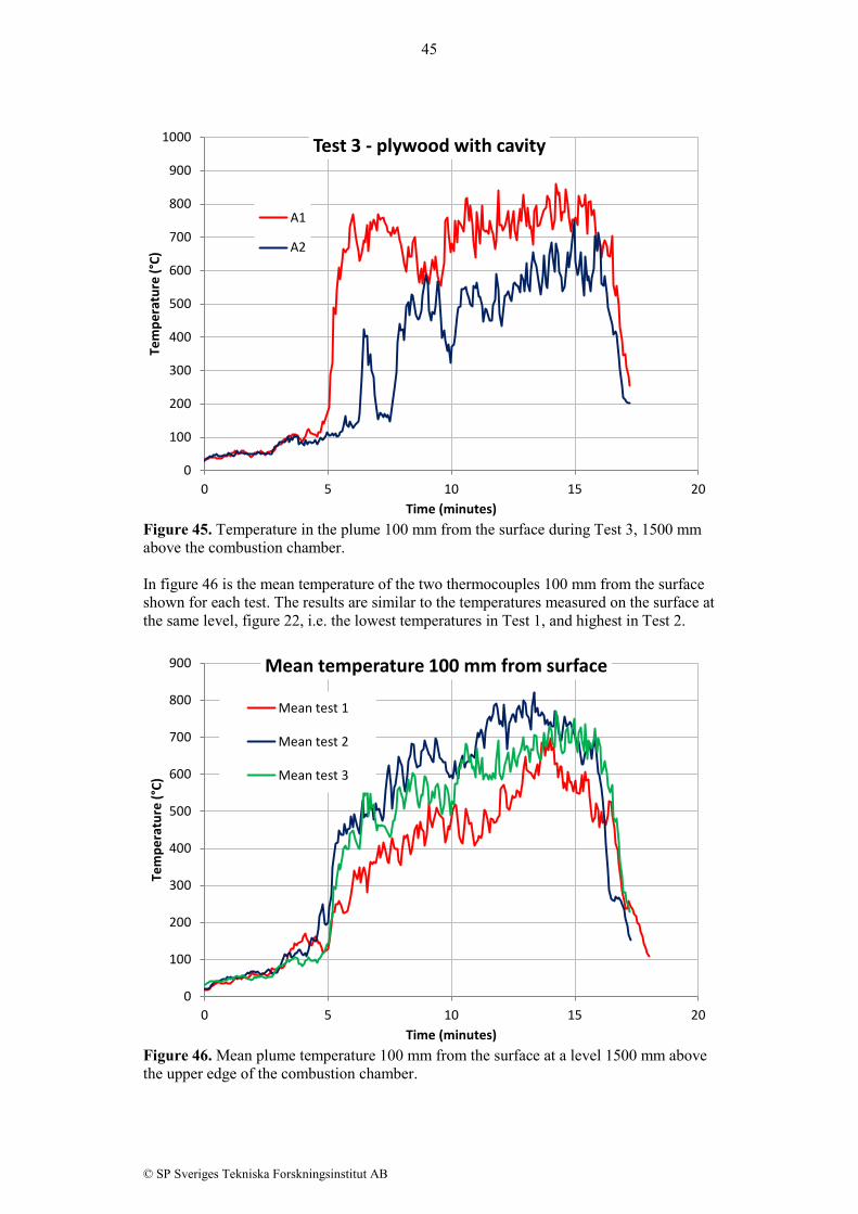
Figure 45. Temperature in the plume 100 mm from the surface during Test 3, 1500 mm above the combustion chamber. In figure 46 is the mean temperature of the two thermocouples 100 mm from the surface shown for each test. The results are similar to the temperatures measured on the surface at the same level, figure 22, i.e. the lowest temperatures in Test 1, and highest in Test 2.
Figure 46. Mean plume temperature 100 mm from the surface at a level 1500 mm above the upper edge of the combustion chamber.
0
100
200
300
400
500
600
700
800
900
1000
0 5 10 15 20
Tem
pera
ture
(°C)
Time (minutes)
Test 3 - plywood with cavity
A1
A2
0
100
200
300
400
500
600
700
800
900
0 5 10 15 20
Tem
pera
ture
(°C)
Time (minutes)
Mean temperature 100 mm from surface
Mean test 1
Mean test 2
Mean test 3
46
© SP Sveriges Tekniska Forskningsinstitut AB
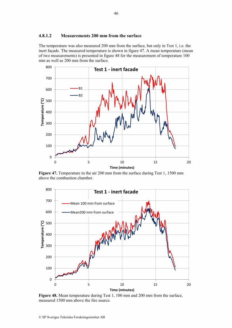
4.8.1.2 Measurements 200 mm from the surface The temperature was also measured 200 mm from the surface, but only in Test 1, i.e. the inert façade. The measured temperature is shown in figure 47. A mean temperature (mean of two measurements) is presented in figure 48 for the measurement of temperature 100 mm as well as 200 mm from the surface.
Figure 47. Temperature in the air 200 mm from the surface during Test 1, 1500 mm above the combustion chamber.
Figure 48. Mean temperature during Test 1, 100 mm and 200 mm from the surface, measured 1500 mm above the fire source.
0
100
200
300
400
500
600
700
800
0 5 10 15 20
Tem
pera
ture
(°C)
Time (minutes)
Test 1 - inert facade
B1
B2
0
100
200
300
400
500
600
700
800
0 5 10 15 20
Tem
pera
ture
(°C)
Time (minutes)
Test 1 - inert facade
Mean 100 mm from surface
Mean200 mm from surface

47
© SP Sveriges Tekniska Forskningsinstitut AB
4.8.1.3 Measurements in the cavity The temperature was also measured in the cavity in Test 3, centrally between the lightweight concrete backing and the plywood. The test results at a level 1500 mm above the fire source are shown in figure 49.
Figure 49. Temperature in the cavity 1500 mm above the fire source during Test 3. 4.8.2 Air temperature 2700 mm above the combustion
chamber 4.8.2.1 Measurements 100 mm from the surface The measured temperature 100 mm from the surface at a level 2700 mm above the edge of the opening of the combustion chamber is presented in figures 50 – 52, one figure for each test. The results clearly show that the fire was more severe on the left side of the specimen in all three tests.
0
100
200
300
400
500
600
0 5 10 15 20
Tem
pera
ture
(°C)
Time (minutes)
Test 3 - plywood with cavity Temperature in cavity
D1
D2
48
© SP Sveriges Tekniska Forskningsinstitut AB
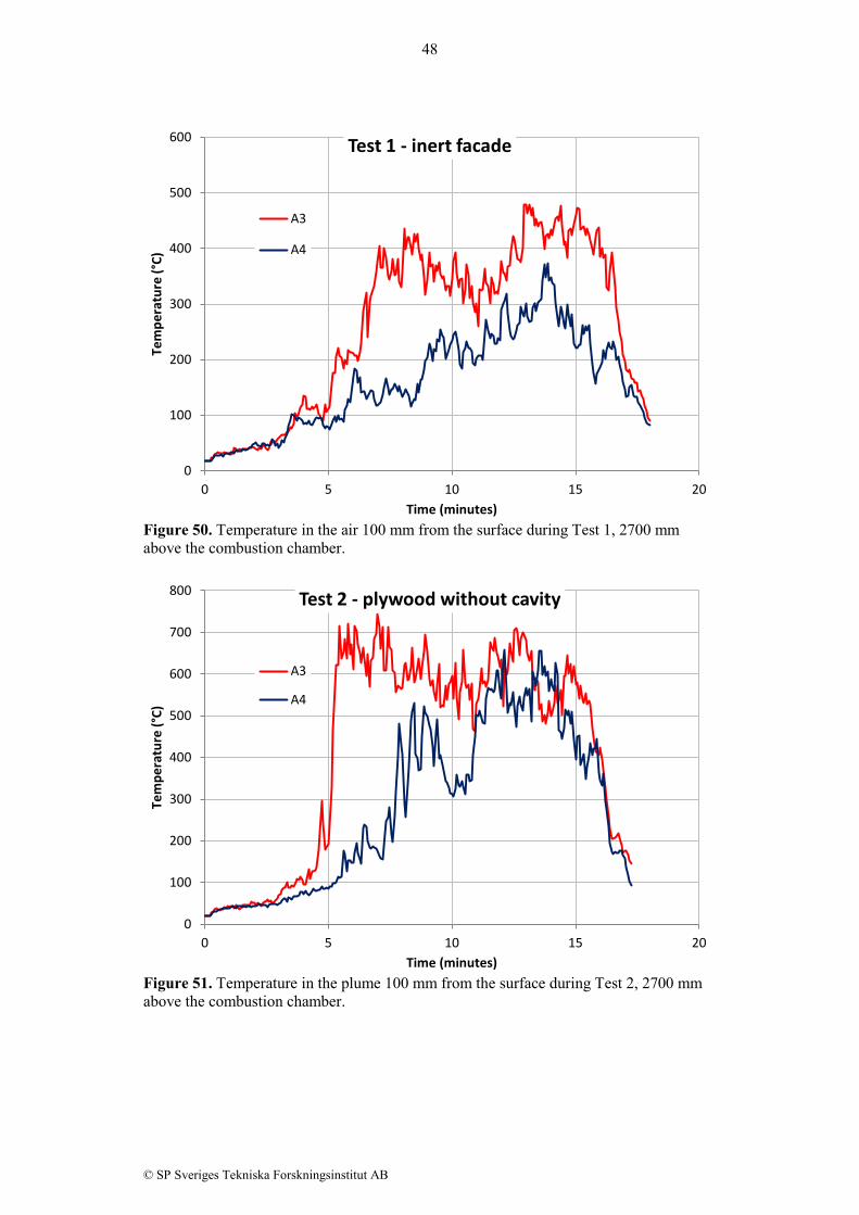
Figure 50. Temperature in the air 100 mm from the surface during Test 1, 2700 mm above the combustion chamber.
Figure 51. Temperature in the plume 100 mm from the surface during Test 2, 2700 mm above the combustion chamber.
0
100
200
300
400
500
600
0 5 10 15 20
Tem
pera
ture
(°C)
Time (minutes)
Test 1 - inert facade
A3
A4
0
100
200
300
400
500
600
700
800
0 5 10 15 20
Tem
pera
ture
(°C)
Time (minutes)
Test 2 - plywood without cavity
A3
A4

49
© SP Sveriges Tekniska Forskningsinstitut AB
Figure 52. Temperature in the air 100 mm from the surface during Test 3, 2700 mm above the combustion chamber. In figure 53 is the mean temperature of the two thermocouples 100 mm from the surface shown for each test. The results are similar to the temperatures measured on the surface at the same level, figure 27, i.e. the lowest temperatures in Test 1, and highest in Test 2.
Figure 53. Mean plume temperature 100 mm from the surface at a level 2700 mm above the upper edge of the combustion chamber.
0
100
200
300
400
500
600
700
800
900
0 5 10 15 20
Tem
pera
ture
(°C)
Time (minutes)
Test 3 - plywood with cavity
A3
A4
0
100
200
300
400
500
600
700
0 5 10 15 20
Tem
pera
ture
(°C)
Time (minutes)
Mean temperature 100 mm from surface
Mean test 1Mean test 2Mean test 3

50
© SP Sveriges Tekniska Forskningsinstitut AB
4.8.2.2 Measurements 200 mm from the surface The temperature was also measured 200 mm from the surface, but only in Test 1, i.e. the inert façade. The measured temperature is shown in figure 54. A mean temperature (mean of two measurements) is presented in figure 55 for the measurement of temperature 100 mm as well as 200 mm from the surface.
Figure 54. Temperature in the plume 200 mm from the surface during Test 1, 2700 mm above the combustion chamber.
Figure 55. Mean temperature during Test 1 100 mm and 200 mm from the surface measured 2700 mm above the fire source.
0
50
100
150
200
250
300
350
400
450
500
0 5 10 15 20
Tem
pera
ture
(°C)
Time (minutes)
Test 1 - inert facade
B3
B4
0
50
100
150
200
250
300
350
400
450
0 5 10 15 20
Tem
pera
ture
(°C)
Time (minutes)
Test 1 - inert facade
Mean 100 mm from surface
Mean 200 mm from surface
51
© SP Sveriges Tekniska Forskningsinstitut AB
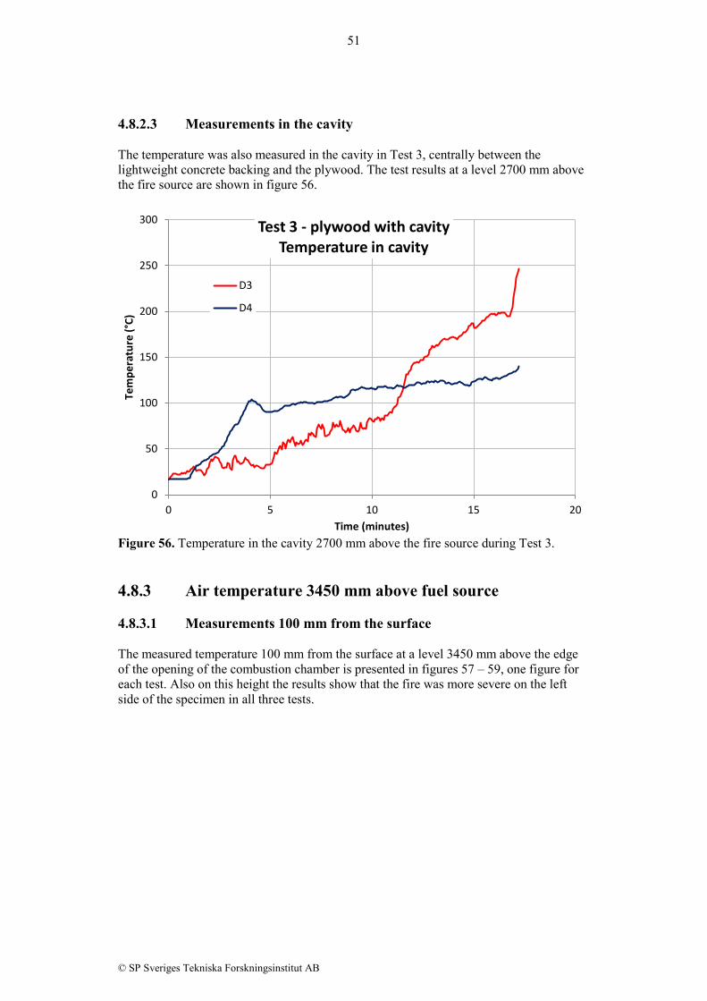
4.8.2.3 Measurements in the cavity The temperature was also measured in the cavity in Test 3, centrally between the lightweight concrete backing and the plywood. The test results at a level 2700 mm above the fire source are shown in figure 56.
Figure 56. Temperature in the cavity 2700 mm above the fire source during Test 3. 4.8.3 Air temperature 3450 mm above fuel source 4.8.3.1 Measurements 100 mm from the surface The measured temperature 100 mm from the surface at a level 3450 mm above the edge of the opening of the combustion chamber is presented in figures 57 – 59, one figure for each test. Also on this height the results show that the fire was more severe on the left side of the specimen in all three tests.
0
50
100
150
200
250
300
0 5 10 15 20
Tem
pera
ture
(°C)
Time (minutes)
Test 3 - plywood with cavity Temperature in cavity
D3
D4

52
© SP Sveriges Tekniska Forskningsinstitut AB
Figure 57. Temperature in the air 100 mm from the surface during Test 1, 3450 mm above the combustion chamber.
Figure 58. Temperature in the air 100 mm from the surface during Test 2, 3450 mm above the combustion chamber.
0
50
100
150
200
250
300
350
400
450
0 5 10 15 20
Tem
pera
ture
(°C)
Time (minutes)
Test 1 - inert facade
A5
A6
0
100
200
300
400
500
600
700
800
0 5 10 15 20
Tem
pera
ture
(°C)
Time (minutes)
Test 2 - plywood without cavity
A5
A6

53
© SP Sveriges Tekniska Forskningsinstitut AB
Figure 59. Temperature in the air 100 mm from the surface during Test 3, 3450 mm above the combustion chamber. In figure 60 is the mean temperature of the two thermocouples 100 mm from the surface shown for each test. The results are similar to the temperatures measured on the surface at the same level, figure 32, i.e. the lowest temperatures in Test 1, and approximately the same temperature in Test 2 and Test 3 except at the end of the test where Test 3 show higher temperature..
Figure 60. Mean air temperature 100 mm from the surface at a level 3450 mm above the upper edge of the combustion chamber.
0
100
200
300
400
500
600
700
800
900
0 5 10 15 20
Tem
pera
ture
(°C)
Time (minutes)
Test 3 - plywood with cavity
A5
A6
0
100
200
300
400
500
600
700
0 5 10 15 20
Tem
pera
ture
(°C)
Time (minutes)
Mean temperature 100 mm from surface
Mean test 1Mean test 2Mean test 3
54
© SP Sveriges Tekniska Forskningsinstitut AB
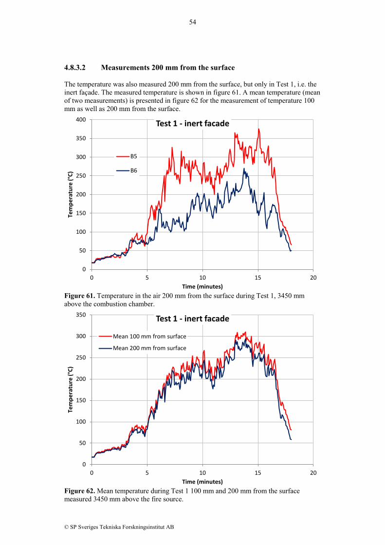
4.8.3.2 Measurements 200 mm from the surface The temperature was also measured 200 mm from the surface, but only in Test 1, i.e. the inert façade. The measured temperature is shown in figure 61. A mean temperature (mean of two measurements) is presented in figure 62 for the measurement of temperature 100 mm as well as 200 mm from the surface.
Figure 61. Temperature in the air 200 mm from the surface during Test 1, 3450 mm above the combustion chamber.
Figure 62. Mean temperature during Test 1 100 mm and 200 mm from the surface measured 3450 mm above the fire source.
0
50
100
150
200
250
300
350
400
0 5 10 15 20
Tem
pera
ture
(°C)
Time (minutes)
Test 1 - inert facade
B5
B6
0
50
100
150
200
250
300
350
0 5 10 15 20
Tem
pera
ture
(°C)
Time (minutes)
Test 1 - inert facade
Mean 100 mm from surface
Mean 200 mm from surface

55
© SP Sveriges Tekniska Forskningsinstitut AB
4.8.3.3 Measurements in the cavity The temperature was also measured in the cavity in Test 3, centrally between the lightweight concrete backing and the plywood. The test results at a level 3450 mm above the combustion chamber are shown in figure 63.
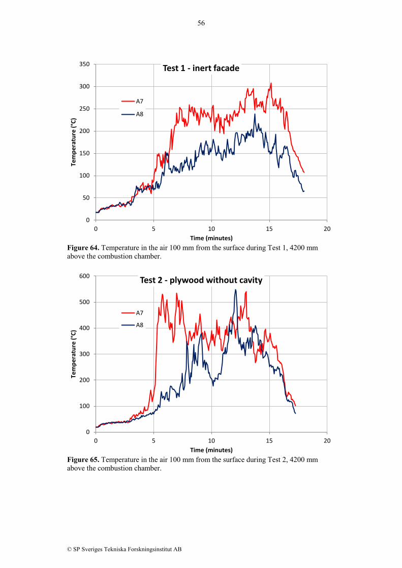
Figure 63. Temperature in the cavity 3450 mm above the fire source during Test 3. 4.8.4 Air temperature 4200 mm above combustion chamber 4.8.4.1 Measurements 100 mm from the surface The measured temperature 100 mm from the surface at a level 4200 mm above the edge of the opening of the combustion chamber is presented in figures 64 – 66, one figure for each test.
0
50
100
150
200
250
300
350
400
450
500
0 5 10 15 20
Tem
pera
ture
(°C)
Time (minutes)
Test 3 - plywood with cavity Temperature in cavity
D5
D6
56
© SP Sveriges Tekniska Forskningsinstitut AB
Figure 64. Temperature in the air 100 mm from the surface during Test 1, 4200 mm above the combustion chamber.
Figure 65. Temperature in the air 100 mm from the surface during Test 2, 4200 mm above the combustion chamber.
0
50
100
150
200
250
300
350
0 5 10 15 20
Tem
pera
ture
(°C)
Time (minutes)
Test 1 - inert facade
A7
A8
0
100
200
300
400
500
600
0 5 10 15 20
Tem
pera
ture
(°C)
Time (minutes)
Test 2 - plywood without cavity
A7
A8

57
© SP Sveriges Tekniska Forskningsinstitut AB
Figure 66. Temperature in the air 100 mm from the surface during Test 3, 4200 mm above the combustion chamber. In figure 67 is the mean temperature of the two thermocouples 100 mm from the surface shown for each test. The results are similar to the temperatures measured on the surface at the same level, figure 37, i.e. the lowest temperatures in Test 1, and approximately the same temperature in Test 2 and Test 3 except at the end of the test where Test 3 show higher temperature..
Figure 67. Mean air temperature 100 mm from the surface at a level 4200 mm above the upper edge of the combustion chamber.
0
100
200
300
400
500
600
0 5 10 15 20
Tem
pera
ture
(°C)
Time (minutes)
Test 3 - plywood with cavity
A7
A8
0
50
100
150
200
250
300
350
400
450
500
0 5 10 15 20
Tem
pera
ture
(°C)
Time (minutes)
Mean temperature 100 mm from surface
Mean test 1Mean test 2Mean test 3
58
© SP Sveriges Tekniska Forskningsinstitut AB
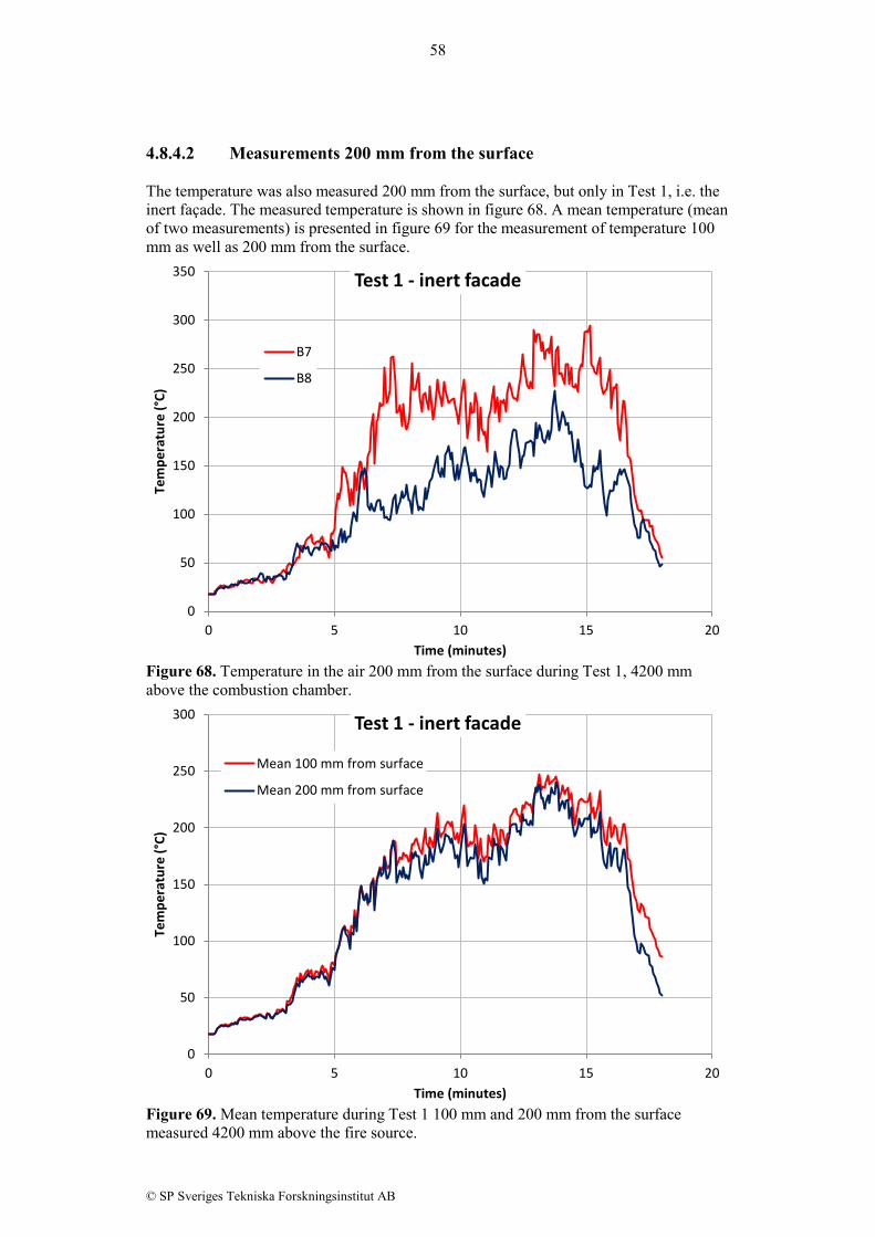
4.8.4.2 Measurements 200 mm from the surface The temperature was also measured 200 mm from the surface, but only in Test 1, i.e. the inert façade. The measured temperature is shown in figure 68. A mean temperature (mean of two measurements) is presented in figure 69 for the measurement of temperature 100 mm as well as 200 mm from the surface.
Figure 68. Temperature in the air 200 mm from the surface during Test 1, 4200 mm above the combustion chamber.
Figure 69. Mean temperature during Test 1 100 mm and 200 mm from the surface measured 4200 mm above the fire source.
0
50
100
150
200
250
300
350
0 5 10 15 20
Tem
pera
ture
(°C)
Time (minutes)
Test 1 - inert facade
B7
B8
0
50
100
150
200
250
300
0 5 10 15 20
Tem
pera
ture
(°C)
Time (minutes)
Test 1 - inert facade
Mean 100 mm from surface
Mean 200 mm from surface

59
© SP Sveriges Tekniska Forskningsinstitut AB
4.8.4.3 Measurements in the cavity The gas temperature was also measured in the cavity in Test 3, centrally between the lightweight concrete backing and the plywood. The test results at a level 4200 mm above the fire source are shown in figure 70.
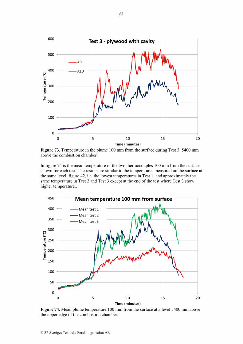
Figure 70. Temperature in the cavity 4200 mm above the fire source during Test 3. 4.8.5 Air temperature 5400 mm above combustion chamber 4.8.5.1 Measurements 100 mm from the surface The measured temperature 100 mm from the surface at a level 5400 mm above the edge of the opening of the combustion chamber is presented in figures 71 – 73, one figure for each test.
0
20
40
60
80
100
120
140
0 5 10 15 20
Tem
pera
ture
(°C)
Time (minutes)
Test 3 - plywood with cavity Temperature in cavity
D7
D8

60
© SP Sveriges Tekniska Forskningsinstitut AB
Figure 71. Temperature in the air 100 mm from the surface during Test 1, 5400 mm above the combustion chamber.
Figure 72. Temperature in the air 100 mm from the surface during Test 2, 5400 mm above the combustion chamber.
0
50
100
150
200
250
300
0 5 10 15 20
Tem
pera
ture
(°C)
Time (minutes)
Test 1 - inert facade
A9
A10
0
50
100
150
200
250
300
350
400
450
0 5 10 15 20
Tem
pera
ture
(°C)
Time (minutes)
Test 2 - plywood without cavity
A9
A10
61
© SP Sveriges Tekniska Forskningsinstitut AB
Figure 73. Temperature in the plume 100 mm from the surface during Test 3, 5400 mm above the combustion chamber. In figure 74 is the mean temperature of the two thermocouples 100 mm from the surface shown for each test. The results are similar to the temperatures measured on the surface at the same level, figure 42, i.e. the lowest temperatures in Test 1, and approximately the same temperature in Test 2 and Test 3 except at the end of the test where Test 3 show higher temperature..
Figure 74. Mean plume temperature 100 mm from the surface at a level 5400 mm above the upper edge of the combustion chamber.
0
100
200
300
400
500
600
0 5 10 15 20
Tem
pera
ture
(°C)
Time (minutes)
Test 3 - plywood with cavity
A9
A10
0
50
100
150
200
250
300
350
400
450
0 5 10 15 20
Tem
pera
ture
(°C)
Time (minutes)
Mean temperature 100 mm from surface
Mean test 1Mean test 2Mean test 3

62
© SP Sveriges Tekniska Forskningsinstitut AB
4.8.5.2 Measurements 200 mm from the surface The temperature was also measured 200 mm from the surface, but only in Test 1, i.e. the inert façade. The measured temperature is shown in figure 75. A mean temperature (mean of two measurements) is presented in figure 76 for the measurement of temperature 100 mm as well as 200 mm from the surface.
Figure 75. Temperature in the air 200 mm from the surface during Test 1, 5400 mm above the combustion chamber.
Figure 76. Mean temperature during Test 1 100 mm and 200 mm from the surface measured 5400 mm above the fire source.
0
50
100
150
200
250
300
0 5 10 15 20
Tem
pera
ture
(°C)
Time (minutes)
Test 1 - inert facade
B9
B10
0
50
100
150
200
250
0 5 10 15 20
Tem
pera
ture
(°C)
Time (minutes)
Test 1 - inert façade
Mean 100 mm from surface
Mean 200 mm from surface

63
© SP Sveriges Tekniska Forskningsinstitut AB
4.8.5.3 Measurements in the cavity The temperature was also measured in the cavity in Test 3, centrally between the lightweight concrete backing and the plywood. The test results at a level 5400 mm above the fire source are shown in figure 77.
Figure 77. Temperature in the cavity 5400 mm above the fire source during Test 3. 4.9 Temperature below the eave The test method SP Fire 105 include two temperature measurements 100 mm below the eave, one 100 mm from the façade surface and one 400 mm from the façade surface, as described in the text below figure 4. These measurements were made with 0.5 mm thermocouples type K with a welded tip. Figures 78 – 79 show the results obtained in the three tests. In the third test the thermocouple at a distance of 400 mm was out of function, so there are no measurements in this case.
0
50
100
150
200
250
300
350
0 5 10 15 20
Tem
pera
ture
(°C)
Time (minutes)
Test 3 - plywood with cavity Temperature in cavity
D9
D10

64
© SP Sveriges Tekniska Forskningsinstitut AB
Figure 78. Measurements 100 mm from the façade surface, 100 mm below the eave.
Figure 79. Measurements 400 mm from the façade surface, 100 mm below the eave.
0
100
200
300
400
500
600
700
0 5 10 15 20
Tem
pera
ture
(°C)
Time (minutes)
Temperature 100 mm from the façade surface Test 1
Test 2
Test 3
0
100
200
300
400
500
600
700
0 5 10 15 20
Tem
pera
ture
(°C)
Time (minutes)
Temperature 400 mm from the façade surface
Test 1
Test 2

65
© SP Sveriges Tekniska Forskningsinstitut AB
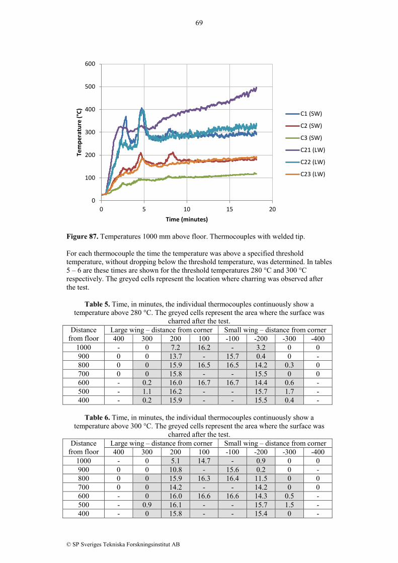
4.10 Results from SBI test The aim with the SBI test was to evaluate different ways to apply thermocouples on the surface for measurement and detection of surface flame spread. The evaluation of flame spread was made after the test. The test specimen was inspected and the charred area was mapped, see figure 80. In the figure is also the position of the thermocouples shown. It was not possible during the test to see the progress of the flame spread with any accuracy, and therefore the presented results are only based on the measurements from the thermocouples during the test, and the visual observation of charring after the test.
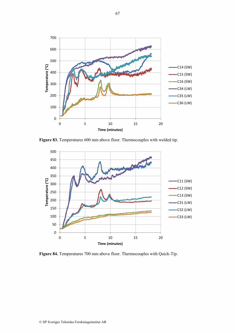
Figure 80. Charring on the test specimen after the test. To the left is the large wing, and to the right the small wing. In figures 81 – 87 are the measured temperatures presented. In the legend are the thermocouple number given as well as which wing they were mounted on. SW is thus the small wing, and LW is the large wing. The numbering is going from the corner outwards, i.e. the lowest number is the thermocouple closest to the corner on that specific wing.

66
© SP Sveriges Tekniska Forskningsinstitut AB
Figure 81. Temperatures 400 mm above floor. Thermocouples with Quick-Tip.
Figure 82. Temperatures 500 mm above floor. Thermocouples with copper disc.
0
100
200
300
400
500
600
0 5 10 15 20
Tem
pera
ture
(°C)
Time (minutes)
C19 (SW)
C20 (SW)
C39 (LW)
C40 (LW)
0
100
200
300
400
500
600
700
0 5 10 15 20
Tem
pera
ture
(°C)
Time (minutes)
C17 (SW)
C18 (SW)
C37 (LW)
C38 (LW)
67
© SP Sveriges Tekniska Forskningsinstitut AB
Figure 83. Temperatures 600 mm above floor. Thermocouples with welded tip.
Figure 84. Temperatures 700 mm above floor. Thermocouples with Quick-Tip.
0
100
200
300
400
500
600
700
0 5 10 15 20
Tem
pera
ture
(°C)
Time (minutes)
C14 (SW)
C15 (SW)
C16 (SW)
C34 (LW)
C35 (LW)
C36 (LW)
0
50
100
150
200
250
300
350
400
450
500
0 5 10 15 20
Tem
pera
ture
(°C)
Time (minutes)
C11 (SW)
C12 (SW)
C13 (SW)
C31 (LW)
C32 (LW)
C33 (LW)

68
© SP Sveriges Tekniska Forskningsinstitut AB
Figure 85. Temperatures 800 mm above floor. Thermocouples welded on steel wire.
Figure 86. Temperatures 900 mm above floor. Thermocouples with copper disc.
0
100
200
300
400
500
600
700
0 5 10 15 20
Tem
pera
ture
(°C)
Time (minutes)
C7 (SW)
C8 (SW)
C9 (SW)
C10 (SW)
C27 (LW)
C28 (LW)
C29 (LW)
C30 (LW)
0
50
100
150
200
250
300
350
400
450
500
0 5 10 15 20
Tem
pera
ture
(°C)
Time (minutes)
C4 (SW)
C5 (SW)
C6 (SW)
C24 (LW)
C25 (LW)
C26 (LW)
69
© SP Sveriges Tekniska Forskningsinstitut AB
Figure 87. Temperatures 1000 mm above floor. Thermocouples with welded tip. For each thermocouple the time the temperature was above a specified threshold temperature, without dropping below the threshold temperature, was determined. In tables 5 – 6 are these times are shown for the threshold temperatures 280 °C and 300 °C respectively. The greyed cells represent the location where charring was observed after the test.
Table 5. Time, in minutes, the individual thermocouples continuously show a temperature above 280 °C. The greyed cells represent the area where the surface was
charred after the test. Distance
from floor Large wing – distance from corner Small wing – distance from corner 400 300 200 100 -100 -200 -300 -400
1000 - 0 7.2 16.2 - 3.2 0 0 900 0 0 13.7 - 15.7 0.4 0 - 800 0 0 15.9 16.5 16.5 14.2 0.3 0 700 0 0 15.8 - - 15.5 0 0 600 - 0.2 16.0 16.7 16.7 14.4 0.6 - 500 - 1.1 16.2 - - 15.7 1.7 - 400 - 0.2 15.9 - - 15.5 0.4 -
Table 6. Time, in minutes, the individual thermocouples continuously show a
temperature above 300 °C. The greyed cells represent the area where the surface was charred after the test.
Distance from floor
Large wing – distance from corner Small wing – distance from corner 400 300 200 100 -100 -200 -300 -400
1000 - 0 5.1 14.7 - 0.9 0 0 900 0 0 10.8 - 15.6 0.2 0 - 800 0 0 15.9 16.3 16.4 11.5 0 0 700 0 0 14.2 - - 14.2 0 0 600 - 0 16.0 16.6 16.6 14.3 0.5 - 500 - 0.9 16.1 - - 15.7 1.5 - 400 - 0 15.8 - - 15.4 0 -
0
100
200
300
400
500
600
0 5 10 15 20
Tem
pera
ture
(°C)
Time (minutes)
C1 (SW)
C2 (SW)
C3 (SW)
C21 (LW)
C22 (LW)
C23 (LW)
70
© SP Sveriges Tekniska Forskningsinstitut AB
5 Analysis and discussion 5.1 Fire source Most façade test methods prescribes type and amount of fuel to be used, as well as the geometry of the combustion chamber. Typical fuels used are wood cribs, heptane and propane. Even if the total amount on energy easily can be determined, regardless of fuel, the burning behaviour will be quite different due to factors such as geometry, air movements around the test set-up, and a number of other factors. In order to have a test method that is repeatable and reproducible it is important that the test specimen is exposed to a well-defined thermal exposure from an external source, which is the same from test to test. When using a free burning fire source, such as heptane or wood cribs, the heat exposure to the test specimen is difficult to adjust if influences from known or unknown factors occurs. Some control can be achieved if the air flow to the combustion chamber can be adjusted or the effective size of the burning area can be changed (the later refers to covering parts of the evaporation surface of a heptane pool fire). Thus the effective heat exposure to the test specimen will depend on two things (i) how the fire will evolve in the combustion chamber and (ii) re-radiation and convective heating originated from the burning of the test specimen. The first factor is initiating the other so there can be cases when a small variation in initial exposure leads to large differences in the fire spread behaviour. This is a crucial question to answer when deciding limits for deviation of the fire in the combustion chamber. Today there is no control of the heat exposure to the test specimen more than a control test that shall be performed periodically, as prescribed in the different methods. This control test is generally made on a well-defined inert façade, and there are requirements that a certain level of heat exposure shall be measured at a certain height. Thus the control is made on a “dummy-test”, and the heat exposure is just assumed to be the same in the sharp tests. An alternative to this procedure would be to measure the heat exposure in each test and use a criterion on the prescribed fire load, in the same way as is done in fire resistance testing. The main difficulty with this approach is that only the heat from the combustion chamber shall be measured, without any contribution of eventual heat production from the test specimen. In the present tests plate thermometers were used to measure the heat from the fire source. The plate thermometers were placed 0.5 m from the opening of the combustion chamber, and they were pointing towards the fire source. This type of measurement could be a way to determine the fire exposure to the test specimen. Figure 88 presents the measurements from the three tests, as well as an example of a minimum temperature curve. There are several options on how to define an acceptable heat exposure. In fire resistance furnace tests plus/minus tolerances are usually used, and they may be different depending on the material in the test specimen. A major difference between a fire resistance test and a façade test with free burning fuel is that the heat exposure in a furnace test can be continuously controlled, which may be difficult in a façade test where only a limited control may be available, if at all. An alternative is to prescribe a minimum temperature on plate thermometer measurements close to the fire source, i.e. a type of effective fire curves which only give the minimum value that must be fulfilled throughout the complete test. By using a minimum temperature curve, i.e. during a test the temperature must always be higher than the prescribed temperature, it would be possible to control that each test have
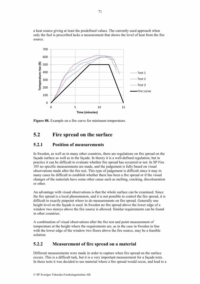
71
© SP Sveriges Tekniska Forskningsinstitut AB
a heat source giving at least the predefined values. The currently used approach when only the fuel is prescribed lacks a measurement that shows the level of heat from the fire source.
Figure 88. Example on a fire curve for minimum temperature. 5.2 Fire spread on the surface 5.2.1 Position of measurements In Sweden, as well as in many other countries, there are regulations on fire spread on the façade surface as well as in the façade. In theory it is a well-defined regulation, but in practice it can be difficult to evaluate whether fire spread has occurred or not. In SP Fire 105 no specific measurements are made, and the judgement is fully based on visual observations made after the fire test. This type of judgement is difficult since it may in many cases be difficult to establish whether there has been a fire spread or if the visual changes of the materials have some other cause such as melting, cracking, discolouration or other. An advantage with visual observations is that the whole surface can be examined. Since the fire spread is a local phenomenon, and it is not possible to control the fire spread, it is difficult to exactly pinpoint where to do measurements on fire spread. Generally one height level on the façade is used. In Sweden no fire spread above the lower edge of a window two storeys above the fire source is allowed. Similar requirements can be found in other countries. A combination of visual observations after the fire test and point measurement of temperature at the height where the requirements are, as in the case in Sweden in line with the lower edge of the window two floors above the fire source, may be a feasible solution. 5.2.2 Measurement of fire spread on a material Different measurements were made in order to capture when fire spread on the surface occurs. This is a difficult task, but it is a very important measurement for a façade tests. In these tests it was decided to use material where a fire spread would occur, and lead to a
0
100
200
300
400
500
600
700
0 5 10 15
Tem
pera
ture
rise
(K)
Time (minutes)
Test 1
Test 2
Test 3
Fire curve

72
© SP Sveriges Tekniska Forskningsinstitut AB
probable failure. In figures 89 – 90 the observations of the damage made after the tests are shown. It is important to note that any eventual fire on the test specimens were distinguished directly after the test (when the fuel was consumed in the combustion chamber). As the figures show as well as the visual observations made during the tests presented in Tables 3-4 above, there was clearly a fire spread and charring on the surface above the lower edge of the upper window. Thus the measurements made during the test should be able to indicate that fire spread occurred.
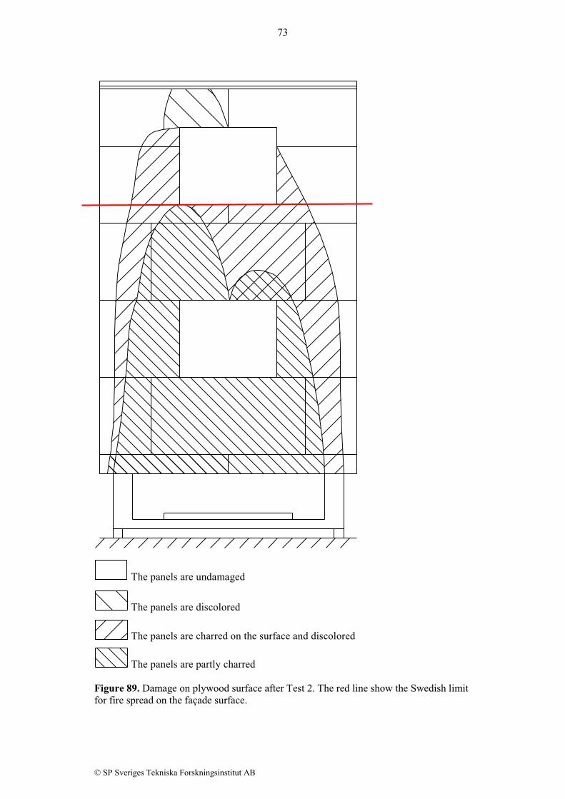
73
© SP Sveriges Tekniska Forskningsinstitut AB
The panels are undamaged
The panels are discolored
The panels are charred on the surface and discolored
The panels are partly charred Figure 89. Damage on plywood surface after Test 2. The red line show the Swedish limit for fire spread on the façade surface.
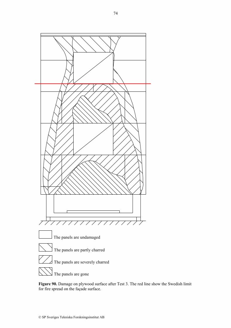
74
© SP Sveriges Tekniska Forskningsinstitut AB
The panels are undamaged
The panels are partly charred
The panels are severely charred
The panels are gone Figure 90. Damage on plywood surface after Test 3. The red line show the Swedish limit for fire spread on the façade surface.

75
© SP Sveriges Tekniska Forskningsinstitut AB
In the present study, clamped thermocouples were used in order to measure the surface temperature. The clamping was made with a small Quick-Tip, i.e. a small metallic cylinder which is clamped and thus jointing the two thermocouple wires together at the measurement point. This thermocouple wire tip was forced into the surface of the façade so the outer metal part of the thermocouple is in line with the surface of the material to be tested. The measurement will thus be an approximate mean temperature of the façade material from the surface to a depth of approximately 1 mm, i.e. it will not be exactly the surface temperature which is very difficult to measure. There are also other factors such as radiation and conduction through the thermocouple that can affect the measurements. The temperature was also measured in the air, 100 mm from the façade surface with 0.5 mm thermocouples with a welded tip. This type of measurement is used in some other methods such as BS 8414-1 [4], but with thicker thermocouples. In figures 91 – 92 is the temperature at the same height as the lower edge of the upper window presented. The figures show the temperature measured on the surface as well as the temperature measured 100 mm from the surface (out in the fire plume). The observations done during the test and the measurements coincide. According to the visual observations of Test 2 (plywood without cavity) burning on the plywood surface at this level was noted after 7 minutes on the left side of the window and after 12 minutes on the right side. During Test 3 (plywood with cavity) the visual observations indicated burning on the plywood surface at this level on the left side of the window at 6.5 minutes and 11 minutes.
Figure 91. Measurements made 100 mm to the left from the lower left corner of the upper window. Red/orange curves show Test 1, blue curves show Test 2, and green curves show Test 3.
0
100
200
300
400
500
600
700
0 5 10 15 20
Tem
pera
ture
(°C)
Time (minutes)
4200 mm - TC 13 Inert facade
Inert facade - gas
Plywood without cavity
Plywood without cavity - gas
Plywood with cavity
Plywood with cavity - gas
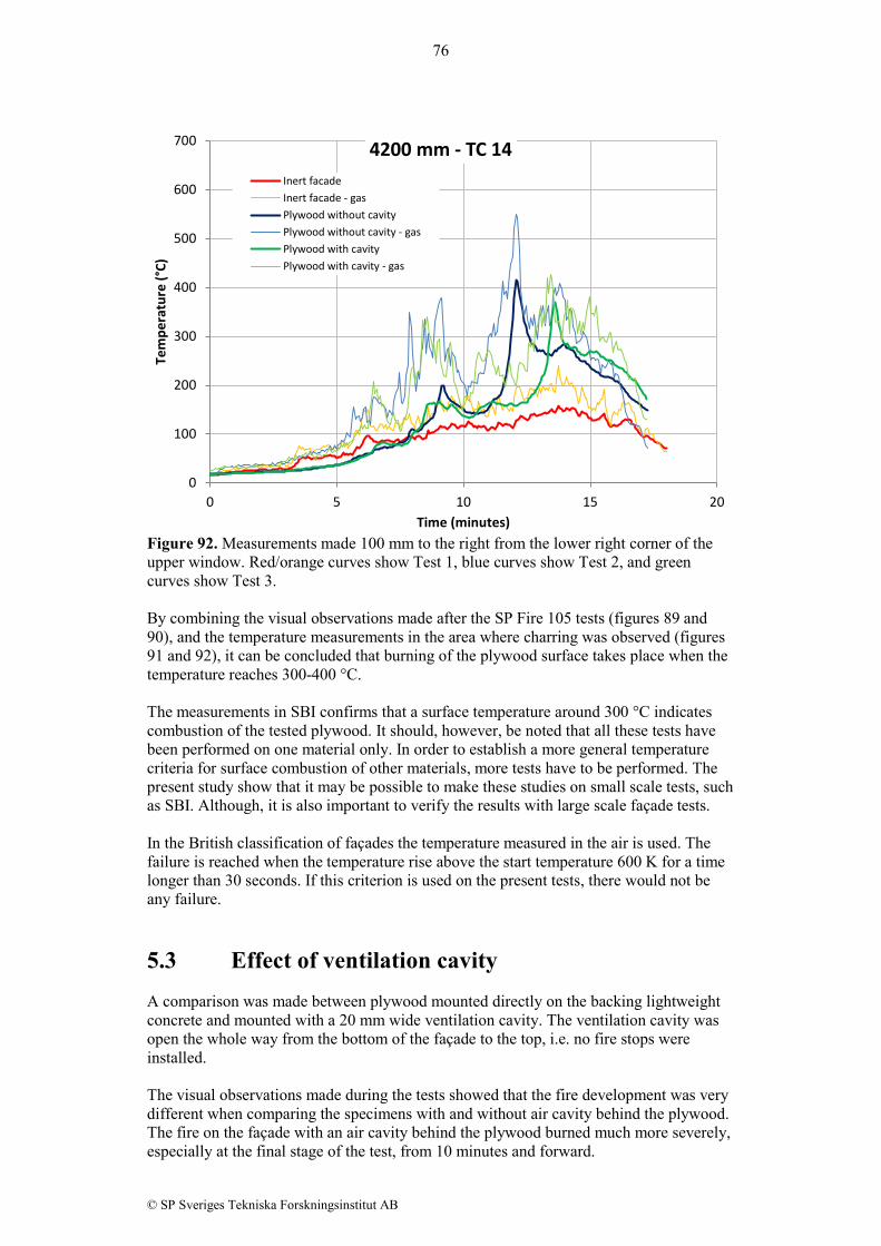
76
© SP Sveriges Tekniska Forskningsinstitut AB
Figure 92. Measurements made 100 mm to the right from the lower right corner of the upper window. Red/orange curves show Test 1, blue curves show Test 2, and green curves show Test 3. By combining the visual observations made after the SP Fire 105 tests (figures 89 and 90), and the temperature measurements in the area where charring was observed (figures 91 and 92), it can be concluded that burning of the plywood surface takes place when the temperature reaches 300-400 °C. The measurements in SBI confirms that a surface temperature around 300 °C indicates combustion of the tested plywood. It should, however, be noted that all these tests have been performed on one material only. In order to establish a more general temperature criteria for surface combustion of other materials, more tests have to be performed. The present study show that it may be possible to make these studies on small scale tests, such as SBI. Although, it is also important to verify the results with large scale façade tests. In the British classification of façades the temperature measured in the air is used. The failure is reached when the temperature rise above the start temperature 600 K for a time longer than 30 seconds. If this criterion is used on the present tests, there would not be any failure. 5.3 Effect of ventilation cavity A comparison was made between plywood mounted directly on the backing lightweight concrete and mounted with a 20 mm wide ventilation cavity. The ventilation cavity was open the whole way from the bottom of the façade to the top, i.e. no fire stops were installed. The visual observations made during the tests showed that the fire development was very different when comparing the specimens with and without air cavity behind the plywood. The fire on the façade with an air cavity behind the plywood burned much more severely, especially at the final stage of the test, from 10 minutes and forward.
0
100
200
300
400
500
600
700
0 5 10 15 20
Tem
pera
ture
(°C)
Time (minutes)
4200 mm - TC 14 Inert facadeInert facade - gasPlywood without cavityPlywood without cavity - gasPlywood with cavityPlywood with cavity - gas

77
© SP Sveriges Tekniska Forskningsinstitut AB
The produced energy from the plywood cladding was almost twice as high in the test with a cavity compared to the test without cavity. This shows that the cavity has a strong effect on the fire behaviour during the test. Although, the measurements on the plywood surface in the cavity and the air temperature in the cavity was unexpectedly low, except at a height 3450 mm above the combustion chamber. Even at the lowest height of measurements, 1500 mm above the combustion chamber, the temperature is low, below 300 °C both on the plywood surface and in the cavity (see figures 21 and 49), except at the end of the test where the temperature increases rapidly.

78
© SP Sveriges Tekniska Forskningsinstitut AB
6 Conclusions Three large scale façade tests has been carried out with the SP Fire 105 test methodology. In all test has a number of extra measurements been performed in order to measure surface temperature, temperatures in the ventilation cavity, plume temperature and heat from the combustion chamber. In addition to the façade tests has a SBI test been done in order to study the surface temperature of plywood with the aim to find at which surface temperature combustion starts, which may be used for the detection of fire spread on a façade surface. The full scale façade tests show that the energy production from the combustible plywood cladding is almost twice as high when a 20 mm fully ventilated air gap is used behind the cladding. This is to some extent expected since the cladding may burn on both sides of the plywood cladding when there is a ventilated air gap, and that chimney effects may have an influence. Although, it was also noted from the measurements of surface temperature (figures 21, 26, 31, 36 and 41) and air temperature in the air cavity (figures 49, 56, 63, 70 and 77) that the temperatures were quite low, generally well below 300 °C, except at one height, 3450 mm above the combustion chamber, where the temperature reached around 600 °C in one point. With these low temperatures the amount of pyrolysis would be quite low, but the calorimetric measurements, as well as the visual observations and temperature measurements on the outer surface shows a significant effect of the ventilation cavity. Although, it should be noted that the temperatures were only measured at some specific locations and that it can have been higher temperatures in other regions. In façade tests there are often a requirement on flame spread on the surface as well as fire spread within the façade in combustible materials. The current technique to evaluate the fire spread is in Sweden by visual inspection after the fire test. In other countries temperature may be measured in the plume some distance from the façade surface. In the present study thermocouples have been mounted on the surface as well as some distance from the surface, and an estimation of the temperature when combustion occurs have been made. For the type of plywood tested, charring occurs when the surface temperature reaches around 300 °C. This was concluded from both the full scale façade tests as well as from a test made with the SBI.

79
© SP Sveriges Tekniska Forskningsinstitut AB
7 References [1] Smolka M., Messerschmidt B., Scott J., le Madec B. “Semi-natural test methods to
evaluate fire safety of wall claddings”, Proc. 1st Int Seminar for Fire Safety of Façades, Paris, France, 14-15 November, 2013
[2] SP Fire 105 – External wall assemblies and façade claddings – Reaction to fire, Issue
5, 1994 [3] Ondrus J., Pettersson O. “Fire hazards of façades with externally applied additional
thermal insulation – Full scale experiments” Report LUTVDG/(TVBB-3025), Lund Institute of Technology, Lund, Sweden, 1986
[4] BS 8414-1 – Fire performance of external cladding systems – Part 1: Test method
for non-loadbearing external cladding systems applied to the face of the building, 2002
[5] ISO 13785-2 – reaction-to-fire tests for façades – Part 2: Large-scale test, 2002 [6] EN 1363-1 – Fire resistance tests – Part 1: General requirements, 2012 [7] Jansson, R. Anderson, J. “Experimental and numerical investigation of fire dynamics
in a façade test rig”, Proc. of Fire Computer Modeling, Santander, Spain, 18-19 October, 2012
[8] EN 13823 – Reaction to fire tests for building products – Building products
excluding floorings exposed to the thermal attack by single burning item, edition 2010+A1:2014
[9] Dalberg M. ”The SP Industry Calorimeter for rate of heat release measurements up
to 10 MW”, SP Report 1992:43, Borås, Sweden, 1992

SP Technical Research Institute of Sweden Box 857, SE-501 15 BORÅS, SWEDEN Telephone: +46 10 516 50 00, Telefax: +46 33 13 55 02 E-mail: [email protected], Internet: www.sp.se www.sp.se
SP Report 2016:16 ISBN 978-91-88349-20-0 ISSN 0284-5172
More information about publications published by SP: www.sp.se/publ
SP Technical Research Institute of Sweden Our work is concentrated on innovation and the development of value-adding technology. Using Sweden's most extensive and advanced resources for technical evaluation, measurement technology, research and development, we make an important contribution to the competitiveness and sustainable development of industry. Research is carried out in close conjunction with universities and institutes of technology, to the benefit of a customer base of about 10000 organisations, ranging from start-up companies developing new technologies or new ideas to international groups.