FIRE PROTECTIVE PRODUCTS PART 2: REACTIVE...
35
ETAG 018 Edition June 2006 GUIDELINE FOR EUROPEAN TECHNICAL APPROVAL OF FIRE PROTECTIVE PRODUCTS PART 2: REACTIVE COATINGS FOR FIRE PROTECTION OF STEEL ELEMENTS EOTA Kunstlaan 40, Avenue des Arts B-1040 Brussels European Organisation for Technical Approvals Europäische Organisation für Technische Zulassungen Organisation Européenne pour l’Agrément Technique
Transcript of FIRE PROTECTIVE PRODUCTS PART 2: REACTIVE...

ETAG 018
Edition June 2006
GUIDELINE FOR EUROPEAN TECHNICAL APPROVALOF
FIRE PROTECTIVE PRODUCTS
PART 2:REACTIVE COATINGS FOR FIRE PROTECTION
OF STEEL ELEMENTS
EOTAKunstlaan 40, Avenue des Arts
B-1040 Brussels
European Organisation for Technical ApprovalsEuropäische Organisation für Technische ZulassungenOrganisation Européenne pour l’Agrément Technique

ETAG 0182
Table of ContentsFOREWORD........................................................................................................................…………...5
Background.............................................................................................................................…….. 5List of reference documents ..........................................................................................……………5
Updating conditions of reference documents ..................................................................................…. 5
1. PRELIMINARIES ........................................................................................................................….. 61.1. Legal basis ........................................................................................................................…..61.2. Status of ETA-Guidelines..................................................................................................... ..6
2. SCOPE .......................................................................................................................................….. 62.1 Scope ..................................................................................................................................... 62.2 Use categories, product families, kits and systems ................................................................6
2.2.1 General ........................................................................................................................62.2.2 Use categories related to environmental conditions ....................................................62.2.3 Use categories related to the element intended to be protected .................................7
2.3 Assumptions........................................................................................................................…7
3. TERMINOLOGY .........................................................................................................................…..73.1. Common terminology and abbreviations................................................................................73.2. Terminology specific to this Part 2 of the ETA-Guideline for Fire Protective Products..........7
4. REQUIREMENTS.....................................................................................................................…....94.0 General ...................................................................................................................…...........94.1. ER 1: Mechanical resistance and stability See Part 1 – General, Table 4.1........................94.2. ER 2: Safety in case of fire See Part 1 – General, Table 4.1................................................94.3. ER 3: Hygiene, health and the environment See Part 1 – General, Table 4.1.................. .94.4. ER 4: Safety in use............................................................................................................…9 4.4.1 Mechanical resistance and stability Not relevant ..............................................…...9
4.4.2 Resistance to impact/movement Not relevant .....................................................…..94.4.3 Adhesion ................................................................................................................….9
4.5. ER 5: Protection against noise See Part 1 – General, Table 4.1...................................…. 94.6. ER 6: Energy, economy and heat retention See Part 1 – General, Table 4.1......................94.7. Aspects of durability, serviceability and identification.......................................................….9
4.7.1 Serviceability..................................................................................................……..…94.7.1.1 Adhesion....................................................................................................………...94.7.2 Durability .......................................................................................................………..104.7.2.1 Corrosion resistance................................................................................………….104.7.2.2 Behaviour under different environmental conditions ......................................…….104.7.2.3 Resistance to chemicals...........................................................................…………104.7.2.4 Resistance to biological attack ..................................................................………..10
4.7.3 Identification...................................................................................................……………..10
5. SPECIFIC METHODS OF VERIFICATION............................................................................…….105.0 General ...........................................................................................................................… .10
5.0.1 Sampling and Test Specimens.....................................................................………...105.0.2 Conditioning of Tests Specimens and Test Conditions ......................................……115.0.3 Dry thickness of the reactive coating system.....................................................….... 115.0.4 Handling with primers and top coats..............................................................………. 115.0.4.1 General.....................................................................................................………… 115.0.4.2 Primer Evaluation .......................................................................................……… 115.0.4.3 Top coat Evaluation.................................................................................…………..12
5.1 Mechanical resistance and stability......................................................................………….. 135.2 Safety in case of fire.......................................................................................…………........ 13
5.2.1 Reaction to fire.............................................................................................………… 135.2.2 Fire Resistance.............................................................................................………. 13
5.3 Hygiene, health and the environment.................................................................................. 145.4 Safety in use...…...................................................................................................................14
5.4.1 Mechanical Resistance & Stability……………………………………………………….. 145.4.2 Resistance to impact/movement........................................................................…… 14

ETAG 0183
5.4.3 Adhesion .....................................................................................................………... 145.5 Protection against noise...........................................................................................……….. 145.6 Energy economy and heat retention ................................................................................….145.7 Aspects of serviceability, durability and identification.......................................................….14
5.7.1 Serviceability...............................................................................................…………. 145.7.1.1 Adhesion..................................................................................................…………. 145.7.2 Durability ........................................................................................................………. 145.7.2.1 Corrosion resistance................................................................................…………..145.7.2.2 Behaviour under different environmental conditions .............................................. 145.7.2.2.1 Initial test..............................................................................................………..… 145.7.2.2.2 Exposure conditions for type Z2: Reactive coating system intended for internal conditions…..……………………………………………………………………………155.7.2.2.3 Exposure conditions for type Z1: Reactive coating system intended for internal conditions with high humidity………………………………………………………….165.7.2.2.4 Exposure conditions for Type Y: Reactive coating system intended for internal and semi-exposed conditions.……...............................................…………………165.7.2.2.5 Exposure conditions for Type X: Reactive coating system intended for all
conditions………………………………………………………………………………. 165.7.2.3 Resistance to chemicals........................................................................……………165.7.2.4 Resistance to biological attack …..........................................................…………… 165.7.3 Identification ……………………………………………………………………………….. 16
6. ASSESSING AND JUDGING OF THE FITNESS FOR USE OF PRODUCTS FOR AN INTENDEDUSE................................................................................................................................…………. 186.1 Mechanical resistance and stability........................................................................................ 186.2 Safety in case of fire.............................................................................................................. 18
6.2.1 Reaction to fire...................................................................................................…… 186.2.2 Fire resistance ..........................................................................................………… 18
6.3 Hygiene, health and the environment....................................................................................…… 186.4 Safety in use..........................................................................................................................…. 18
6.4.1 Mechanical resistance and stability ........................................................................... 186.4.2 Resistance to impact/movement................................................................................ 186.4.3 Adhesion ....................................................................................................................18
6.5 Protection against Noise .......................................................................................................…. 186.6 Energy economy and heat retention .....................................................................................…. 186.7 Aspects of serviceability, durability and identification............................................................…. 18
6.7.1 Serviceability.............................................................................................................. 196.7.1.1 Adhesion................................................................................................................. 196.7.2 Durability ....................................................................................................................196.7.2.1 Corrosion Resistance ............................................................................................. 196.7.2.2 Behaviour under different environmental conditions ...........................................…196.7.2.2.1 Initial test...........................................................................................................…196.7.2.2.2 Criteria for exposure conditions for use categories Z1, Z2, Y and X..................…196.7.2.3 Resistance to chemicals (optional test) ..................................................................196.7.2.4 Resistance to biological attack (optional test) ........................................................ 196.7.3 Identification............................................................................................................... 19
7. ASSUMPTIONS AND RECOMMENDATIONS UNDER WHICH THE FITNESS FOR USE OF THEPRODUCTS IS ASSESSED ....................................................................................................... 20
7.1 Design of the works...............................................................................................................…… 207.2 Transport and storage...........................................................................................................…… 207.3 Execution of the works..........................................................................................................…….217.4 Maintenance and repair ........................................................................................................…… 21
8. EVALUATION OF CONFORMITY............................................................................................….. 228.1 EC decision ...........................................................................................................................……228.2 Responsibilities .....................................................................................................................……22
8.2.1 Tasks for the manufacturer.......................................................................................… 228.2.1.1 Factory production control .................................................................................…. 228.2.2 Tasks for the approved body ...................................................................................… 248.2.2.1 Initial type testing of the product)........................................................................…... 248.2.2.2 Assessment of the FPC system -initial inspection and continuing surveillance.........24
8.2.2.3 Certification of Conformity ......................................................................................…… 24

ETAG 0184
8.3 Documentation ....................................................................................................................…248.4 CE marking and information ...............................................................................................… 24
9 THE ETA CONTENT ............................................................................................................…..25
9.1. The ETA-content...............................................................................................................….. 259.2. Additional information..........................................................................................................…25
ANNEX A Reactive Coatings, Reactive Coating Kits – Initial test (Insulating Efficiency)……………. 26ANNEX B Testing for condition type X ............................................................................………….... 27ANNEX C Testing for conditions type Y .....................................………………………………………. 28ANNEX D Reaction to fire test.........……………………………………………………………………..…29ANNEX E Reactive Coatings – Determination of identification characteristics FINGERPRINT…... 30ANNEX F List of reference documents .....................................................................................….….32ANNEX G Tests procedure for determining the maximum foam height of intumescent materials..… 34

ETAG 0185
FOREWORD
Background
This ETA-Guideline has been drawn up by the EOTA Working Group 11.01/04 Fire Protective Products.This ETA-Guideline – Part 2 “Reactive coatings for fire protection of steel elements” shall be used inconjunction with the ETA-Guideline “Fire protective products” Part 1 “General”. This Complementary Partexpands and/or modifies the requirements given in Part 1 “General”, taking into account the specific fam-ily of products referred to.This ETA-Guideline can be used to issue a ETA for fire protective coatings or fire protective coating kits.In all cases the ETA covers the reactive coating.There are three options:
-Option 1: The ETA only covers the reactive coating product. This option can only be used for prod-ucts that can be used directly on the steel substrate without any primer and/or topcoat.
-Option 2: The ETA covers a reactive coating kit, i.e. in all cases the reactive coating product, anddepending on the kit one (or more) primers and/or one (or more) topcoats and/or one (or more)reinforcements. All components need to be identified, subjected to the assessment and all FPCrequirements. The reactive coating kit shall comprise at least two components.
-Option 3: The ETA is issued for a product in end use conditions. The ETA only covers the reactivecoating product, but one (or more) primers and/or one (or more) topcoats and/or one (or more)reinforcements are also identified. This identification may be specific (e.g. trade name, type) orgeneric (e.g. family of primers). All components of the product in end use conditions are sub-jected to the assessment, but only the reactive coating product is subjected to the FPC require-ments.
Option 1 Option 2: Option 3:Reactive product Reactive Coating Kit Reactive Coating Kit considering
the product in end use conditions
Note: The CE marking in the drawings indicates which component(s) will be covered by the ETA.
Manufacturers are responsible for ensuring that products covered by an ETA issued on the basis of thispart 2 of ETAG 018, will comply with all relevant requirements from applicable European Directives e.g.Directive 67/548/EEC, Directive 76/548/EEC, Directive 76/769/EEC, Directive 91/155/EEC, Directive1999/45/EC and
• Directive 1999/77/EC: Before affixing the CE Marking. Approval bodies are responsible for ensuring thatthe ETA addresses all relevant provisions, when and where applicable.
List of reference documentsThis ETA-Guideline Part 2 incorporates, by dated or undated reference, provisions from other publica-tions. These normative references are cited at the appropriate places in the text and the publications arelisted in annex F. For dated references subsequent amendments to, or revisions of these publications,apply to this ETAG only when incorporated in it by amendment or revision. For undated references thelatest dated revision of the publication referred to, applies.
Updating conditions of reference documentsThe updating conditions of the ETA-Guidelines are given in Part 1 "General" - clause 1.1.

ETAG 0186
Section One:INTRODUCTION
1. PRELIMINARIES
1.1. LEGAL BASISThe legal basis of the ETA-Guideline is given in Part 1: “General” – clause1.1. No existing ETA-Guideline is superseded.
1.2. STATUS OF ETA-GUIDELINESThe Status of this ETA-Guideline is given in Part 1: “General” – clause 1.2.
2. SCOPE
2.1 SCOPEThis part 2 shall be used in conjunction with Part 1 “General”.This ETA-Guideline Part 2 “Reactive Coatings for fire protection of steel elements” specifiesthe terminology and definitions, the specific methods of verification and for identification. It alsogives guidance on the installation instructions and for the Attestation of Conformity for theseproducts.An ETA issued on the basis of this ETA-Guideline will cover reactive coatings or reactivecoating kits to be used on steel elements. In each case, the ETA will cover at least the reactivecoating layer (see Foreword). This ETAG can also be used as a basis for the assessment ofreactive coatings or reactive coating kits on cast iron elements. Properties that are independ-ent of the substrate can be assessed with steel substrate (e.g. durability).This ETA-Guideline does not cover
1 factory-coated steel elements, where the ‘product’ is the element itself.2 products placed on the market in the form of prefabricated, preformed shells which are
applied to structural elements on site.
2.2 USE CATEGORIES, PRODUCT FAMILIES, KITS AND SYSTEMS2.2.1 GeneralThe ETA-Guideline 018 is divided into the following parts:
-Part 1: General -Part 2: Reactive coatings for fire protection of steel elements-Part 3: Renderings and rendering kits intended for fire resisting applications-Part 4: Fire Protective Boards, Slab and Mat Products and Kits
In this part, additional specifications are given for reactive coating systems. The componentspecifications are either specified in:
-in this ETA-Guideline; or-European technical specifications as referred to in the Construction Products Directive,
i.e. harmonized European product standards as published by CEN or EuropeanTechnical Approvals as published by EOTA.
2.2.2 Use categories related to environmental conditionsThe use categories related to the type of environmental conditions are based on the generalprinciples specified in Part 1 ”General” of this ETAG, clause 2.2.2. The use categories are thefollowing:
-Type X: Reactive coating system intended for all conditions (internal, semi-exposedand exposed)
-Type Y: Reactive coating system intended for internal and semi-exposed conditions.Semi exposed includes temperatures below zero, but no exposure to rain and

ETAG 0187
limited exposure to UV (but UV is not assessed).-Type Z1: Reactive coating system intended for internal conditions (excluding tempera-
tures below zero) with high humidity.1
-Type Z2: Reactive coating system intended for internal conditions (excluding tem-peratures below zero) with humidity classes other than Z1
Note: Products that meet the requirements for type X, meet the requirements for all other types. Productsthat meet the requirements for type Y, also meet the requirements for types Z1 and Z2. Productsthat meet the requirements for type Z1, also meet the requirements for type Z2.
Note, however, that although a reactive coating system is intended for internal use only theconstruction process may result in a reactive coating system being subjected to exposed con-ditions for a period before the building envelope is closed. There are two possibilities:1 Special provisions are made to temporarily protect the exposed reactive coatings ac-
cording to the instructions of the manufacturer which are referenced in the ETA.2 The reactive coating should be evaluated as if it were to be used for exposed applica-
tions (type X).The product's resistance to specific environmental conditions is not covered in this part of theETAG and may be assessed on a case by case basis as necessary. The approval body shallobtain suitable evidence for the assessment and present details in the ETA.
2.2.3 Use categories related to the element intended to be protectedThe use categories are identified in Part 1 – General as Types 1 – 10. This Guideline coversthe application of reactive coatings to use types 4, 6 and 10.
2.3 ASSUMPTIONSThe assumptions made are given in Part 1 "General" - clause 2.3The provisions, test and assessment methods in this guideline, or referred to, have been writ-ten based on the assumed working life of the product for the intended use of 10 years. Theprovisions are based upon the current state of art and the available knowledge and experi-ence.An estimated working life of 25 years shall only be assumed in the case where the applicantcan offer, in addition to the above, for examination by the Approval Body, sufficient docu-mented proof to demonstrate the use of the reactive coating system for a period of 25 years inthe environmental conditions claimed (see 2.2.2).
3. TERMINOLOGY
3.1. COMMON TERMINOLOGY AND ABBREVIATIONSThe common terminology and abbreviations are given in Part 1 "General" - clause 3.1
3.2. TERMINOLOGY SPECIFIC TO THIS PART 2 OF THE ETA-GUIDELINE FOR FIREPROTECTIVE PRODUCTSFor the purpose of this ETA-Guideline Part 2 the following definitions apply:Reactive coating system: Fire protective reactive coating systems normally comprise theprimer, the reactive coating and the top coat. In some instances a reinforcing mesh is used.Note: It is possible that a single coating may perform one or more of the functions described, which
means that the “reactive coating system” comprises only the reactive coating.
1 These conditions apply for internal humidity class 5 in accordance with EN ISO 13788

ETAG 0188
Primer: a coating applied directly to a suitably prepared steel surface to provide corrosionprotection and/or to act as an aid to the adhesion of the reactive coating.
Reactive coating: coating which is specially formulated to provide a chemical reaction uponheating such that the physical form changes and in so doing provides fire protection by thermalinsulation and cooling effects
Intumescent layer expand by foaming when exposed to heat in the conditions of a fire
Ablative layer could slightly expand due to the formation of a char when exposed to fire. En-ergy will be consumed in fire conditions through chemical and or physical processes creatingthe charred substance.
Topcoat: coating applied over the reactive coating as a protection against environmental deg-radation and/or for decorative purposes.Reinforcing mesh: mesh of relatively small aperture size (e.g. metal, fibre glass) applied inclose proximity or fixed to the substrate, which allows penetration of the reactive coating, toproduce a good key.
Kit: For a definition of the term “kit” see EC Guidance Paper C. For kits based on reactivecoatings the kit will be composed by the reactive coating product, and, at least, one of theother components (primer, topcoat and/or reinforcing mesh) of the reactive coating system.See also the foreword with the explanation of kits and products in end use conditions.
Batch: The unit or quantity of production in a single complete production operation. The vol-ume which constitutes a batch in converting the raw material into the finished product is called“batch size”.

ETAG 0189
Section two :GUIDANCE FOR THE ASSESSMENT
OF THE FITNESS FOR USE
4. REQUIREMENTS
4.0 GENERALThe performance requirements, establishing the fitness for use of Fire Protective Productsbased on reactive coating systems shall be in accordance with Part 1 “General” – chapter 4and with the following specific stipulations for this family of products.
4.1 ER 1: MECHANICAL RESISTANCE AND STABILITY See Part 1 – General, Table 4.1
4.2. ER 2: SAFETY IN CASE OF FIRE See Part 1 – General, Table 4.1If there is a national requirement for a resistance to fire classification using the slow heatingcurve ("IncSlow" according to EN 13501-2; see also ENV 13381-4) the product shall be sub-jected to the appropriate test.
4.3. ER 3: HYGIENE, HEALTH AND THE ENVIRONMENT See Part 1 – General, Table 4.1
4.3.1 Air and/or water permeability See Part 1 – General
4.3.2 Release of dangerous substancesFurther restrictions compared to the European directives (see FOREWORD) may be imposedby single member states, If there exists national restrictions concerning dangerous substancesconsider the database of the European Commission.
4.4. ER 4: SAFETY IN USE
4.4.1 Mechanical resistance and stability Not relevant
4.4.2 Resistance to impact/movement Not relevant
4.4.3 AdhesionNote: This requirement has been placed under 4.7.1 Serviceability, but is related to other re-quirements as well, in particular to ER2 and ER4.
4.5. ER 5: PROTECTION AGAINST NOISE See Part 1 – General, Table 4.1
4.6. ER 6: ENERGY, ECONOMY AND HEAT RETENTION See Part 1 – General, Table 4.1
4.7 ASPECTS OF DURABILITY, SERVICEABILITY AND IDENTIFICATIONThe performance of the fire protective products shall not change significantly during the work-ing life. Therefore the properties on which the suitability and in particular the Fire resistancebehaviour depend shall not be significantly affected by ambient physico-chemical effects suchas corrosion or degradation in particular caused by environmental conditions (e.g. moisture,chemical agents).
4.7.1 Serviceability4.7.1.1 AdhesionThe reactive coating system shall adhere to the substrates, such that the system will have the
ETAG 01810
required fire protective performance.
4.7.2 DurabilityThe performance of fire protective reactive coating systems shall not deteriorate during theirassumed intended working life so as to affect significantly the performance of the products inrelation to fulfilling all the Essential Requirements 2 to 6, especially the protective effects incase of fire. The reactive coating system should be durable under service conditions, such as:
-Humidity: see 4.7.2.1-Variations of temperature and relative humidity, rain and radiation of the sun: see 4.7.2.2-Chemical attack: see 4.7.2.3-Biological attack: see 4.7.2.4
4.7.2.1 Corrosion resistanceThe reactive coating system shall not react adversely with the intended substrate(s) and whererequired the primer and/or the reactive coating shall provide corrosion protection to the sub-strate.4.7.2.2 Behaviour under different environmental conditionsThe fire behaviour of the reactive coating system shall not change significantly during theworking life, if reactive coating systems are used in the defined use conditions. The ETA-Applicant's shall claim durability of the reactive coating system according to the use categoriesin chapter 2.2.2.4.7.2.3 Resistance to chemicalsReactive coating systems may or may not be influenced in their function by chemicals. Forspecific areas of application, where reactive coating systems may be exposed to chemicalsadditional verifications may be required.The testing of resistance to chemicals is optional testing in accordance with the ETA-Applicant´claims.4.7.2.4 Resistance to biological attackReactive coatings may be influenced in their function by biological effects, i.e. mould growth orsubject to deterioration due to attack by insects or mammals, e. g. rodents. This ETA-Guideline foresees no assessment to cover this eventuality. In general, it is an assumption thatdesign provisions will prevent deterioration from occurring (see chapter 7). Where approvalbodies expect biological attack to be of particular importance for specific products, additional,case-by-case assessment should take place, taking into account the nature of the biologicalagent.
4.7.3 IdentificationThe materials used in the fire protective reactive coating system shall be identifiable as to theirproperties which have an influence on the ability of the reactive coating system to fulfil the Es-sential Requirement.The determination of characteristics and properties of the product for identification purposesshall be specified in tests listed in section 5.7.3
5. SPECIFIC METHODS OF VERIFICATION
5.0 GENERALThis Chapter refers to the verification methods used to determine the various aspects of per-formance of the product in relation to the requirements for the works (calculation, tests, engi-neering knowledge, site experience, etc.) as set out in chapter 4. The methods of verificationgiven in Part 1 "General" - chapter 5 apply, except where modified or specified below (see ta-ble 5.1).

ETAG 01811
5.0.1 Sampling and Test SpecimensWhere possible, samples of the product for all approval tests shall be taken at the manufac-turing site (storage, production) and shall be representative of the reactive coating or reactivecoating kit for which approval is being sought.All samples for test specimens for each product shall be representative for the product placedonto the market. All samples for test specimens shall be taken at the same time, and from thesame batch, in accordance with EC Guidance Paper K, ensuring that approval test results canbe validated for initial type testing under attestation of conformity (see chapter 8). If samplingat the same time is impossible for practical reasons, measures shall be taken to ensure that allsamples taken have identical constituents and composition. In the latter case the ApprovalBody needs to provide relevant evidence of measures taken to those responsible for attesta-tion of conformity.The specimens for approval tests shall as far as possible be prepared at the same time in or-der to minimize differences caused by variations in specimen preparation. This is in order torelate the characteristics of the material to the performance achieved.Where relevant, the specimen substrate shall be a grade of steel (S designation) to the EN10025series (excluding S 185) of standards. Engineering grades (E designation) shall not beused. Where galvanized steel is used as substrate, EN ISO 1460 or EN ISO 1461 apply.The surface of the steel used for the specimens shall reflect the surface conditions claimed bythe ETA-Applicant, as specified in the application instructions for the product.
5.0.2 Conditioning of Tests Specimens and Test ConditionsThe coating on the test specimens shall be applied and fully cured according to the ETA-applicants instructions.Except where special conditioning is specified in a referenced test method the prepared testspecimens shall be conditioned at (23 ± 2)
oC and (50 ± 5) % relative humidity.
The laboratory conditions at the start of fire testing shall be (20 ± 10)°C according toEN 1363-1.
5.0.3 Dry thickness of the reactive coating systemThe dry film thickness of all layers of the reactive coating system shall be determined directlyupon the test specimen, once the coating is fully dried. The thickness shall be measured usingan instrument employing either the electro-magnetic induction principle or the eddy currentprinciple with a probe contact diameter of at least 2,5 mm according to EN ISO 2808.The measurements points should be uniformly distributed over the surface of the test samplewith a minimum number of 40 per m2.
5.0.4 Assessment Approach for primers and top coats5.0.4.1 GeneralFire protective reactive coating systems normally comprise the primer, the reactive coating andthe top coat. Some reactive coatings can be applied directly on the substrate without primerFor a reactive coating kit or reactive coating kit in end use conditions, consisting of one reac-tive layer and one or more primers and/or one or more top coats, both primers and top coatsmay be referred to specifically (by trade name and type) or generically ( generic products orgeneric families, in case of primers). Specific or generic products shall be specified in the ETAaccording to the available technical specifications (e.g. EN or ETA) and, when this is not pos-sible, by reference to proprietary items, physical dimensions and material performance. In caseof primers, when they are not specific, reference to the generic families indicated in 5.0.4.2should be made.5.0.4.2 Primer EvaluationThere are two options for assessing primers and covering primers in the ETA:Specific primers or Generic primersThe most commonly used primer families are the following:
-Short/medium oil alkyd primers;-Two component epoxy primers;-Zinc rich epoxy primers (containing about 85% by weight of metallic zinc powder);

ETAG 01812
-Zinc silicate primers
Note 1: Primers not covered by the families identified above may be grouped in other families of primersbased on the binder (e.g. oil alkyd, epoxy), carrier (organic solvent/water) and pigment (e. g. in-hibitive or non-inhibitive) type.
Durability testing with a primer from the generic type of zinc rich epoxy primer does not covergalvanized steel, for instance hot dip galvanised steel. Galvanized steel is treated as anotherform of “primer” and has to be tested separately.All tests/assessments according to 5.2 to 5.7 shall be carried out with a primer chosen by theapplicant. However, where the reactive coating system is intended to be used with more thanone primer, an insulation efficiency test is necessary for the additional primers. Only oneprimer from a primer family is subjected to testing.Note 2: It is assumed that the result “pass” ( see 6.7.2.2.1) within the insulation efficiency test is an indi-
cation of a comparable behaviour in all other tests (e. g. fire resistance tests, durability test).
It is recognized that in the majority of cases the steel elements will arrive on site alreadyprimed. In such instances, it is necessary for the reactive coating applicator to ensure that theprimer is compatible with the reactive coating. For this case provisions are given in chapter 7.However, where the primer is found to be a type not covered by the ETA, the appliedcoating is not covered by the ETA.5.0.4.3 Top coat EvaluationAll tests according to chapter 5.7.2 should be conducted without a top coat unless the top coatis necessary to provide the required performance under the particular exposure conditions. Inthis case the reactive coating should be tested with the specified top coat.If the reactive coating system is claimed to be equally suitable with and without topcoat forenvironmental conditions types Z1 and Z2 the initial tests (5.7.2.2.1) shall be performed withpanels with and without topcoat to show that the topcoat has no influence on the insulationefficiency. For determining the insulation efficiency after exposure, it is sufficient to perform thetests without topcoat. The top coat is specified in the ETA. The colour of the topcoat has noinfluence on the result of the durability assessment for types Z1 and Z2. Therefore there is noneed to test different colours of the topcoat. The ETA is valid for all top coat colours.For environmental use categories type Y and type X the test results could be influenced by thevarious top coat types and their colours. No generic approach is possible in relation to the typeof top coat and the applicant has to test all top coats. However, in order to cover all colours ofa particular top coat, a colour having an index L< 50 on the CIELAB2 scale (see ISO 7724)shall be selected for test. The decision to choose the colour of the top coat used in durabilityassessment is taken by the Approval Body and the ETA-Applicant. The test results are validfor the tested top coat and all its different colours.Table 5.1: Relationship between ETAG paragraph on product performance, product charac-
teristics and ETAG paragraph on verification method
ER ETAG section on product perform-ance
ETAG section on verification methodof product characteristics
Reactive Coating systemER1 Not relevant for these products
ER2 4.2. Safety in case of fire 5.2.1 Reaction to fire
5.2.2 Fire Resistance
ER3 4.3 Hygiene, health and the environment4.3.1 Air and/or water permeability 4.3.2Release of dangerous substances
5.3 See Part 1 General 5.3.1 Not relevant5.3.2 Release of dangerous substances
2 “Commission International de le Eclairage” (CIE) system of colour space defines lightness/darkness (L)
scale in CIELAB units. White is defined as L = 100 and black as L = 0.

ETAG 01813
ER4 4.4 Safety in use 4.4.1 Mechanical resis-tance and stability
Not relevant
4.4.2 Resistance to impact/movement Not relevant
4.4.3 Adhesion No specific verification but see 5.7.1 Serv-iceability
ER5 4.5 Protection against noise 5.5 See Part 1 General
ER6 4.6 Energy, economy and heat retention 5.6 See Part 1 General
4.7 Durability, serviceability and identification
4.7.1 Serviceability
4.7.1.1 Adhesion
4.7.2 Durability
4.7.2.1 Corrosion resistance
4.7.2.2 Behaviour under different environ-mental conditions
4.7.2.3 Resistance to chemicals
4.7.2.4 Resistance to biological attack
5.7 Durability, serviceability and identification
5.7.1 Serviceability
5.7.1.1 Adhesion
5.7.2 Durability
5.7.2.1 Corrosion resistance
5.7.2.2 Behaviour under different envi-ronmental conditions
5.7.2.2.1 Initial test
5.7.2.2.2 Exposure conditions for TypeZ2: Reactive coating system intendedfor internal conditions
5.7.2.2.3 Exposure conditions for TypeZ1: Reactive coating system intendedfor internal conditions with high humidity
5.7.2.2.4 Exposure conditions for TypeY: Reactive coating system intended forinternal and semi-exposed conditions
5.7.2.2.5 Exposure conditions for TypeX: Reactive coating system intended forall conditions
5.7.2.3 Resistance to chemical
5.7.2.4 Resistance to biological attack
4.7.3 Identification 5.7.3 Identification
5.1 MECHANICAL RESISTANCE AND STABILITYThis Essential Requirement is not relevant for these products.
5.2 SAFETY IN CASE OF FIRE5.2.1 Reaction to fireThe reactive coating system shall be tested, using the test method(s) relevant for the corre-sponding reaction to fire class, in order to be classified according to EN 13501-1. Where aEuro-class better than F for reaction to fire is a requirement in national building regulationstests should be carried out using the test methods relevant for the corresponding reaction tofire class.Guidance on mounting and fixing arrangements for tests in accordance with the test methodsis given in Annex D of this document. If the reactive coating system is intended to be used withor without a top coat then both situations shall be tested.
5.2.2 Fire ResistanceIn order for an ETA to be issued for the reactive coating or reactive coating kit it shall be thesubject of at least one fire resistance test and shall be classified according to EN 13501-2. Themethod of application of water based paints does not significantly affect the results so anymethod may be used but spray application is recommended. Solvent based paints are much

ETAG 01814
more sensitive to the method of application and spray application should be used unless themanufacturer specifies a different method which should then be used.Note 1: If there is a national requirement for a resistance to fire classification using the slow
heating curve ("IncSlow" according to EN 13501-2) the smouldering curve according toEN 1363-2 shall be used when the product is subjected to a resistance to fire test. Thetest method is described in ENV 13381-4.
5.3 HYGIENE, HEALTH AND THE ENVIRONMENT5.3.1 Air and/or water permeabilityNot relevant
5.3.2 Release of dangerous substancesRegarding the release/content of dangerous substances the ETA-applicant shall declare thatno substances as specified in EC-database are used for the production of his reactive coatingsystem.
5.4 SAFETY IN USE
5.4.1 Mechanical resistance and stabilityNot relevant
5.4.2 Resistance to impact/movementNot relevant
5.4.3 AdhesionNo specific verification method (but see 5.7.1 Serviceability)
5.5 PROTECTION AGAINST NOISENo specific verification method.
5.6 ENERGY ECONOMY AND HEAT RETENTIONNo specific verification method.
5.7 ASPECTS OF SERVICEABILITY, DURABILITY AND IDENTIFICATION
5.7.1 Serviceability
5.7.1.1 AdhesionNo specific verification method.Adhesion of the reactive coating system (primer, reactive coating layer with/without top coat) tothe substrate (and cohesion of the system) is covered by testing the insulation efficiency (see5.7.2.2.1).
5.7.2 Durability
5.7.2.1 Corrosion resistanceThe tests under 5.7.2.2 will serve to indicate whether the coating has an adverse effect on theprimer and/or substrate and whether the reactive coating system provide corrosion protectionto the substrate. The durability testing shall be carried out with the same reactive coatingsystem used for the fire resistance tests.
5.7.2.2 Behaviour under different environmental conditions

ETAG 01815
The need to conduct each of the following tests is determined by the claimed use categoryrelated to environmental conditions for the reactive coating product or reactive coating kit (see2.2.2 and table 5.7.2.2).
5.7.2.2.1 Initial testThe durability assessment is achieved through indirect testing, i.e. the measurement of insu-lating efficiency as a ‘proxy’ characteristic that is related to the fire protective behaviour of thereactive coating system. Durability is demonstrated by comparing “insulating efficiency” on theinitial and on the exposed specimen.For preparation of test specimen, test procedure and test criteria see Annex A. The product orkit is assessed for a use category as claimed by the ETA-Applicant and therefore, the insulat-ing efficiency on minimum 2 initial samples (5.7.2.2.1) is compared with the insulating effi-ciency on minimum 2 weathered samples, in accordance with 5.7.2.2.2, 5.7.2.2.3, 5.7.2.2.4 or5.7.2.2.5. Table 5.2 specifies the tests and the number of tests depending on the possibilitiesfor the different reactive coating systems.Table 5.2: Minimum number of test specimens regarding the assessment approach for
primer(s) and top coat(s) and the durability requirement (see 5.0.4 and 5.7.2)
No Required approval content Tests ac-cording tosection
minimumnumber ofspecimens
1 Reactive coating systems with one primer withoutand with top coat for type Z2
5.7.2.2.15.7.2.2.2(without topcoat)
2
2
1a Additional generic or specific primer(s) 5.7.2.2.1 + 2 x n 1)
1b with top coat: (to test every claimed top coat) 5.7.2.2.1 + 2 x m 2)
2 Reactive coating systems with one primer onlywith top coat for type Z2
5.7.2.2.15.7.2.2.2
22
2a Additional generic or specific primer(s) 5.7.2.2.1 + 2 x n 1)
2b Additional top coat(s): 5.7.2.2.1 + 2 x m 2)
3 Reactive coating systems with one primer withoutand with top coat for types Z2 and Z1
5.7.2.2.15.7.2.2.3(without topcoat)
22
3a Additional generic or specific primer(s) 5.7.2.2.1 + 2 x n 1)
3b with top coat (to test every claimed top coat) 5.7.2.2.1 + 2 x m 2)
4 Reactive coating systems with one primer onlywith top coat for types Z2 and Z1
5.7.2.2.15.7.2.2.2
22
4a Additional generic or specific primer(s) 5.7.2.2.1 + 2 x n 1)
4b Additional top coat(s): 5.7.2.2.1 + 2 x m 2)
3 Reactive coating systems with one primer withtop coat for type Y (including types Z1 and Z2)
5.7.2.2.15.7.2.2.4
22
3a Additional generic or specific primer(s) 5.7.2.2.1 + 2 x n 1)
3b Additional top coat(s) (to test every top coat withonly one colour)
5.7.2.2.15.7.2.2.4
+ 2 x m 2) +2 x m 2)

ETAG 01816
4 Reactive coating systems with one primer withtop coat for type X (including types Y, Z1 and Z2)
5.7.2.2.15.7.2.2.5
22
4a Additional generic or specific primer(s) 5.7.2.2.1 + 2 x n 1)
4b Additional top coat(s) (to test every top coat withonly one colour)
5.7.2.2.15.7.2.2.5
+ 2 x m 2) +2 x m 2)
1) n = number of claimed generic or specific primers in additionto the one tested in number 1, 2, 3 or 42) m = number of claimed top coats and one colour
5.7.2.2.2 Exposure conditions for type Z2: Reactive coating system intended for internal condi-tions
The test specimen shall be placed in a vertical position into the test chamber and exposed tothe following cycle:
- 4 h at (23 ± 3) °C and (80 ± 5) %RH- 16 h at (40 ± 3) °C and (50 ± 5) %RH- 4 h at (5 ± 3) °C and (50 ± 5) %RH
The cycle shall be repeated 21 times without interruption. After exposure the specimen shallbe tested according to Annex A.The chamber temperature change shall be at a rate of 1,5 K/min ± 0,5 K/min. During the pe-riod of temperature change the change of humidity is not controlled, but condensation shouldbe avoided. The duration of temperature change is included in the duration of the 16 h cycle.
5.7.2.2.3 Exposure conditions for type Z1: Reactive coating system intended for internal condi-tions with high humidity
The test shall be carried out to the following cycle:- 8 hours at (40 ± 3) °C and (98 ± 2) % RH- 16 hours at (23 ± 3) °C and cabinet off and open to atmosphere
The test cycle shall be repeated 21 times in total. After exposure the specimens shall be testedaccording to Annex A.
5.7.2.2.4 Exposure conditions for Type Y: Reactive coating system intended for internal andsemi-exposed conditions
The test specimens shall be stored in a vertical position into the test chamber and exposed tothe test conditions. The special requirements of the test method are described in Annex C.After exposure the specimens shall be tested according to Annex A.
5.7.2.2.5 Exposure conditions for Type X: Reactive coating system intended for all conditionsThe test specimens shall be stored in a vertical position into the test chamber and exposed tothe test conditions. The principles of the test method is according to EN ISO 4892-3: 1999,mode 2, table A.1 combination. After this exposure to UV and sprayed water the specimensshall be tested under special conditions as described in Annex B. After exposure the speci-mens shall be tested according to Annex A.
5.7.2.3 Resistance to chemicalsTo determine chemical resistance, as claimed by the ETA-applicant, after subjecting (at least)two specimens to chemicals in accordance with EN ISO 2812-1, the test specimens shall betested according to Annex A. The insulation efficiency after exposure to chemicals is comparedwith the insulation efficiency of the initial test (see 6.7.2.2.1).
5.7.2.4 Resistance to biological attacksee chapter 4.7.2.4
5.7.3 IdentificationRegardless of which option is chosen for the reactive coating or reactive coating kit (see Fore-

ETAG 01817
word) all components of the reactive coating system (primer, reactive layer and top coat) shallbe clearly identified according to the following table.
Table 5.3: Testing for identification
PROPERTIES Primers(if any)
Reactivecoating
Top coat(if any)
Reinforce-ments (if any)
Technical data x x x x
Colour (visualverification)
x x x
Density x x x
Non-volatilecontent
x x x
Fingerprint ac-cording to AnnexE or formulation(optional)
x
Geometry x

ETAG 01818
6. ASSESSING AND JUDGING OF THE FITNESS FOR USE OF PRODUCTS FORAN INTENDED USEThis Chapter details the performance requirements to be met by reactive coating systems(chapter 4) into precise and measurable criteria (as far as possible and proportional to the im-portance of the risk) or qualitative terms, related to the products and their intended use, usingthe outcome of the verification methods (chapter 5).
6.1 MECHANICAL RESISTANCE AND STABILITYThis Essential Requirement is not relevant to fire protective products.6.2 SAFETY IN CASE OF FIRE
6.2.1 Reaction to fireThe Fire Protective Products shall be classified in accordance with EN 13501-1
6.2.2 Fire resistanceBecause a reactive coating system does not possess fire resistance in its own right the classi-fication applies to the protected element, including the reactive coating system, and not to theprotection itself.Classification with respect to fire resistance is undertaken in accordance with EN 13501-2 andshall specify the protected elements. Classification can also be undertaken for cast iron on abasis of an assessment approach.For reactive coating systems ‘No performance determined’ shall not be an option.For tests with a smouldering fire curve the assessment criteria are given in EN 13501-2 andthe test standards referenced therein.
6.3 HYGIENE, HEALTH AND THE ENVIRONMENT6.3.1 Air and/or water permeabilityNot relevant6.3.2 Release of dangerous substancesSee 5.3.2
6.4 SAFETY IN USE
6.4.1 Mechanical resistance and stabilityNot relevant
6.4.2 Resistance to impact/movementNot relevant
6.4.3 AdhesionSee chapter 6.7.1.
6.5 PROTECTION AGAINST NOISENo specific requirements.
6.6 ENERGY ECONOMY AND HEAT RETENTIONNo specific requirements.
6.7 ASPECTS OF SERVICEABILITY, DURABILITY AND IDENTIFICATIONFor all tests required in chapter 5.7.1 and 5.7.2 the test result is a pass/fail criterion. No test

ETAG 01819
results or threshold values (e. g. time to reach 500°C) are specified in the ETA.
6.7.1 Serviceability
6.7.1.1 AdhesionNo specific assessment (but see 6.7.2)
6.7.2 Durability
6.7.2.1 Corrosion ResistanceA ”pass” result in the tests according to section 5.7.2.2 is sufficient to demonstrate that thereactive coating has no adverse effect on the primer and that the reactive coating system pro-vide corrosion protection to the substrate..If ETA-applicants claim that their product or kit provides or contributes to the corrosion protec-tion of the steel element it is intended to protect against fire, the product, or the kit component(or components together) shall be classified in accordance with the relevant part of EN ISO12944.
6.7.2.2 Behaviour under different environmental conditions
6.7.2.2.1 Initial testDurability is demonstrated by comparing the performance of unexposed test specimens withspecimens exposed to artificial ageing. The insulation efficiency test is also used within theassessment approach for primers and top coats. The test method and the evaluation of thetest results is described in Annex A. For the criteria for the test result “pass” see 6.7.2.2.2.
6.7.2.2.2 Criteria for exposure conditions for use categories Z1, Z2, Y and XThe test result is deemed a “pass” when the average time to achievement of the critical steeltemperature (t500) determined in the durability tests is not less than 85% of the average timet500 (time to reach a steel temperature of 500°C) of the initial tests. To remove influences dueto the variability of the thickness of the reactive coating, the relationship thickness/t500 may beassumed as linear. No single result of exposed specimens shall be less than 80% of the aver-age time t500 of the initial test.Where the result falls outside these criteria, additional 4 specimens may be exposed, testedand assessed. All 4 specimens shall fulfil the pass criteria.These criteria for exposure conditions for use categories Z1, Z2, Y and X shall also be used forthe evaluation of primers and top coats.
6.7.2.3 Resistance to chemicals (optional test)The assessment criteria shall be in accordance with 6.7.2.2.2.
6.7.2.4 Resistance to biological attack (optional test)See sections 4.7.2.4 and 7.1
6.7.3 IdentificationThe results of the identification test according to the section 5.7.3 shall be kept in the files ofthe Approval Body.

ETAG 01820
7 ASSUMPTIONS AND RECOMMENDATIONS UNDER WHICH THE FITNESSFOR USE OF THE PRODUCTS IS ASSESSED
The results of the identification test according to section 5.7.3 shall be kept in the files of theApproval Body.This chapter sets out the assumptions recommendations for design, installation and execution,packaging, transport and storage, use, maintenance and repair under which the assessment ofthe fitness for use according to the ETAG can be made (only when necessary and in so far asthey have a bearing on the assessment or on the products).
7.1 DESIGN OF THE WORKSSee ETA-Guideline, Part 1.Fire protective reactive coatings and kits should be assessed under the presumption that theelement being protected, the substrate, is suitable for the reactive coating to be used in theway intended and in full compliance with the ETA such that then when installed in the pre-scribed manner the works will comply with all relevant Essential Requirements.Where steel structures have been previously primed with a primer there are two possibilities:
1) The primer could be identified by both the generic description and the product nameand is covered by the ETA.
2) Where unknown primers have been used or the primer is not covered by the ETA theprimer shall be tested or replaced by an approved primer.
Biological attackIn rare cases, deterioration of these products may occur due to biological attack, i.e. mouldgrowth on the products and/or the products being subject to deterioration due to insects ormammals infestation. This ETA-Guideline does not foresee product assessment for resistanceto biological attack, but where approval bodies expect biological attack to be of particular im-portance for specific products, additional, case-by-case assessment should take place (seeclause 4.7.2.4).Moulds and other fungi that may damage products require warm (10°C to 35°C), humid condi-tions (RH > 70%), and a suitable food source. Mould growth is encouraged by dark conditionsand lack of air movement. Design solutions should minimise the possibility of mould growthby ensuring that areas where these products are used can be ventilated sufficiently. Usersshould use the ventilation possibilities offered.Proper water tightness of the building envelope, using appropriate design principles and detailsis essential. During the exposed and partially enclosed phases of construction, to minimise thepotential for mould growth, it is important to minimise the risk of water damage and wet sur-faces due to external factors such as rain, snow, flooding, and high relative humidity. Duringconstruction, the following should be considered to minimise the potential for mould growth:minimising the exposure of interior building products to exterior conditions; protecting storedmaterials from moisture; minimising moisture accumulation within the building; prevent spillageof water within the building; maintaining the integrity of the building envelope componentsthrough ongoing monitoring and inspections; achieving balance control of thermal comfort andrelative humidity in the building; checking all material deliveries to validate that components aredry and clean; reject wet or mouldy materials, and monitoring installations to ensure they re-main clean and dry (including the HVAC systems).In addition, where animals (insects, mammals) might attack these products, design solutionsshould prevent animal access to places where the products have been used and habitablevoids that might harbour animals should be either avoided or sealed.
7.2 TRANSPORT AND STORAGEThe manufacturer has to give information for the transport and storage on an accompanying

ETAG 01821
data sheet or on the containers. The ETA should contain the basic principles of transport andstorage (see clause 9).As a minimum the following should be addressed: storage temperature, way of storage (con-tainer, tank), the necessary information on minimum and maximum temperature for transportand storage. For flammable components or other potentially hazardous materials the instruc-tions shall contain specific guidance on restrictions and/or conditions for handling, transportand storage.
7.3 EXECUTION OF THE WORKSThe manufacturer shall provide an installation guide for his product.The installation guide shall give information about:• List of suitable substrates• Preparation of the surface of the construction (e. g. cleanliness, moisture)• Method of application (e.g. the temperature and humidity conditions before, during and
after application)• Necessary wet film thickness in relation to the dry thickness and measurement method• Required dry thickness of the layer of the reactive coating• Period of time between the application of each component, taking account of exposure
conditions• Curing time of the system• Approved top coat• Equipment parameters• Provisions to protect coatings intended for internal use, if temporarily exposed on site.
7.4 MAINTENANCE AND REPAIRThe manufacturer of the reactive coating should have readily available a procedure for therepair and maintenance of the reactive coating system.

ETAG 01822
Section three :
ATTESTATION OF CONFORMITY (AC)
8. EVALUATION OF CONFORMITY
8.1 EC DECISIONThe EC-decision is given in Part 1 “General” – Clause 8.1.
8.2 RESPONSIBILITIESUnless modified or supplemented below, the responsibilities are given in Part 1 “General” –Clause8.2.
8.2.1 Tasks for the ETA-holder
8.2.1.1 Factory production control (FPC)See Part 1 "General".
8.2.1.2 Inspection and TestingThe ETA holder shall carry out all inspections and tests required by the factory productioncontrol system in order to maintain compliance with specification. This inspection and testingshall be applicable to the product and to all kit components as appropriate. There are threeoptions to deliver an ETA for reactive coating systems: Product, Kit or a kit in end use condi-tions (see FOREWORD).The routes for placing the reactive coating system on the market are:
-the ETA-holder manufacturers the product or all kit components-the ETA-holder manufacturers some kit components-the ETA-holder does not manufacture anything, but places them on the market.
In all cases, the ETA-holder's FPC-system must address appropriate conformity testing or in-spection of the product or of all items in the kit to ensure consistency of performance of thereactive coating system. In the case where the product or all kit items are manufactured on theETA-holder's behalf, the FPC should address sample inspection of incoming material, processverification and testing the finished product. In circumstances where the ETA-holder manu-facturers not all or no kit components, the FPC should verify the producer’s declaration ofconformity (based on the supplier’s FPC system that complies with the ETA and the manufac-turer's specifications).Table 8.1 shows the properties that should be controlled and minimum frequencies of control.
Table 8.1: Properties and minimum frequencies of controlNo Property Paragraph, indicating
the relevant testmethod
Threshold (ifany) and toler-ances
Minimum fre-quency of tests
Reactive layer and reactive coating kit
1 Incoming material Declaration of conformity Manufacturer'sdeclaration,
Every delivery
2 Char depth (expansionratio)
e. g. Cylinder test (seeAnnex G) or similar
Manufacturer'sdeclaration,minimum value
Every batch

ETAG 01823
3 Insulating efficiency or anyalternative test designed toensure consistency of fireperformance (to be agreedbetween the Approval Body,the Notified Body and theManufacturer)
e. g. Annex A or similar Manufacturer'sdeclaration, 1)
Every 10th batchor at least onceper month
4 Sag resistance Manufacturer'sspecification
Every batch
5 Viscosity e. g. EN ISO 3219 Every batch
6 Raw material Check thetest results of the supplieraccording to the specifica-tion of the manufacturer ofraw material
Every delivery
7 Curing Every batch
8 Pigment dispersion (fine-ness of the grind)
Every batch
primer
9 Raw material l Check the test results ofthe supplier according tothe specification of themanufacturer of raw ma-terial
Manufacturer'sspecification
Every delivery
10 Viscosity e. g. EN ISO 3219 Every batch
11 Non-volatile content e. g. ISO 3251 Every batch
Top coat
12 Raw material Check the test results ofthe supplier according tothe specification of themanufacturer of raw ma-terial
Manufacturer'sspecification
Every delivery
13 Pigment content colour Every batch
10 Viscosity e. g. EN ISO 3219 Every batch
14 Non-volatile content e. g. ISO 3251 Every batch
Keying mesh
15 Geometry declaration of conformity Manufacturer'sspecification
Every delivery
1) If the result of the test char depth is not sufficient in that case an insulating efficiency testshould be done
ETAG 01824
8.2.2 Tasks for the approved body
8.2.2.1 Initial type testing of the product)See Part 1 - General
8.2.2.2 Assessment of the factory production control system - initial inspection and continuingsurveillance
Subsequently continuing surveillance of factory production control is necessary to ensure con-tinuing conformity with the ETA. The frequency of the surveillance shall be twice a year.
8.2.2.3 Certification of ConformityThe approved body shall issue the Certification of Conformity of the product.
8.3 DOCUMENTATIONSee Part 1 "General" - Clause 8.3.
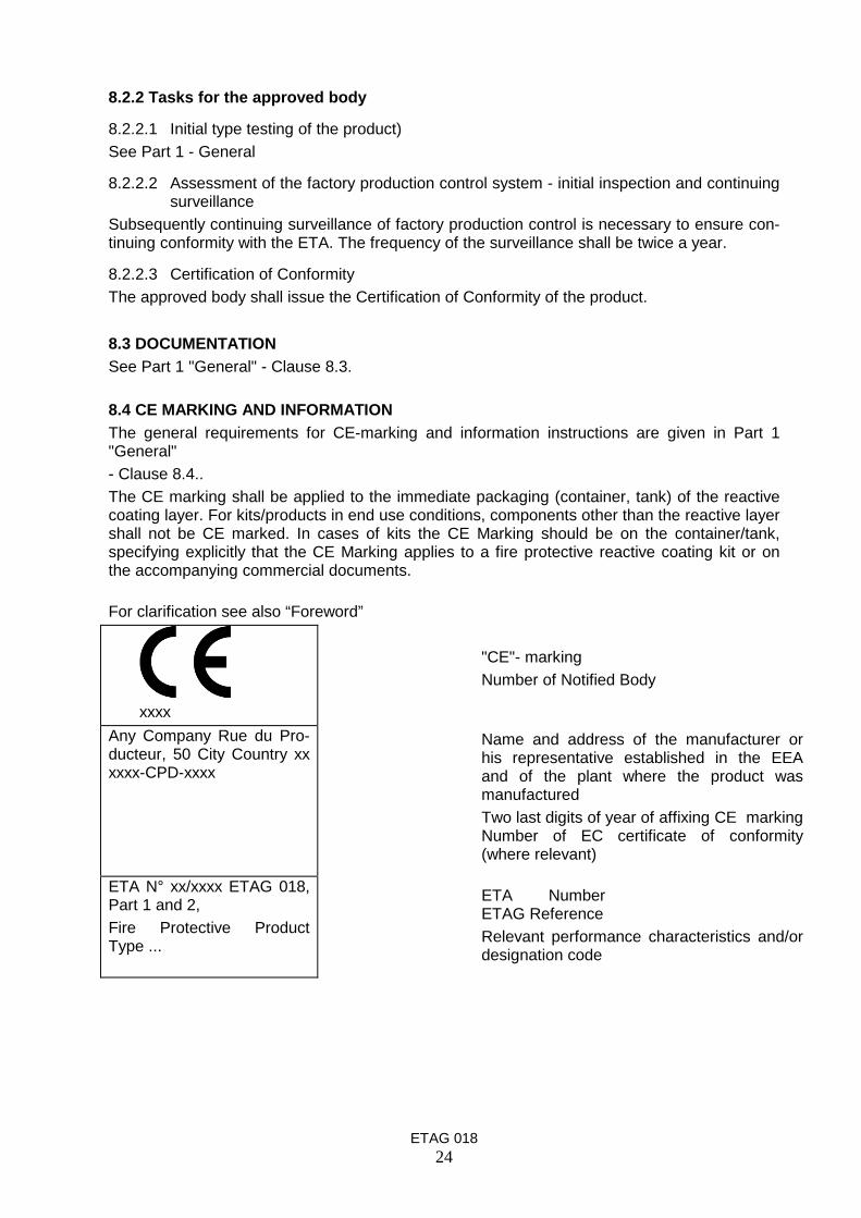
8.4 CE MARKING AND INFORMATIONThe general requirements for CE-marking and information instructions are given in Part 1"General"- Clause 8.4..The CE marking shall be applied to the immediate packaging (container, tank) of the reactivecoating layer. For kits/products in end use conditions, components other than the reactive layershall not be CE marked. In cases of kits the CE Marking should be on the container/tank,specifying explicitly that the CE Marking applies to a fire protective reactive coating kit or onthe accompanying commercial documents.
For clarification see also “Foreword”
xxxxAny Company Rue du Pro-ducteur, 50 City Country xxxxxx-CPD-xxxx
ETA N° xx/xxxx ETAG 018,Part 1 and 2,Fire Protective ProductType ...
"CE"- markingNumber of Notified Body
Name and address of the manufacturer orhis representative established in the EEAand of the plant where the product wasmanufacturedTwo last digits of year of affixing CE markingNumber of EC certificate of conformity(where relevant)
ETA NumberETAG ReferenceRelevant performance characteristics and/ordesignation code

ETAG 01825
Section four :ETA CONTENT
9. THE ETA CONTENT
9.1. THE ETA-CONTENT.The ETA-content is given in Part 1 "General" – clause 9
9.2. ADDITIONAL INFORMATIONAdditional information shall be given regarding:
Area of Application (use for beams and/or columns, 3- and/or 4-sided exposure to fire,minimum thickness of the dried layer of the reactive coating system, application (sprayed,brushed), environment conditions, use on galvanized steel etc) Special provisions for thecomponents of the reactive coating systems (special primers, top coats) Special provisionsfor the production, storage and transport Special provisions for maintenance and repairConformity
In case of kits, the components covered by the kit and in case of products in end use conditionsthe fact that other components are not covered by the ETA.

ETAG 01826
ANNEX AReactive Coatings, Reactive Coating Kits – Initial test (Insulating Efficiency)
A1 GeneralThe small scale furnace fire test shall be carried out under the condition of the standardtime - temperature curve as defined in EN 1363-1.The specimens to be tested should be prepared in accordance with the manufacturers in-structions for the fire protective system concerned. Specimens should then be stored in anatmosphere (23 ± 3) ºC and (50 ± 5) %rh for a period of time as specified by the manu-facturer for drying.After exposure to environment conditions, if any, the specimens should be stored in an at-mosphere (23 ± 3) ºC and (50 ± 5) %rh between the end of the exposure and the fire test-ing for a minimum of 1 week.The coating dry thickness shall be measured and recorded at a minimum number of 40 perm2
uniformly distributed points prior to testing. The coating thickness shall be measured
with instruments using the electromagnetic induction principle (see 5.0.3)A2 Specimens
The specimens shall consist of steel panels having a nominal thickness of 5 mm and aminimum of size 300 mm x 200 mm3. For every requirement a minimum of two specimensshall be tested.For panels, used for durability testing, it will be necessary to apply a protective coating(primer) to the back and edges of these (including all control panels), to prevent rust con-tamination of the cabinet.The primer and the topcoat used as part of the reactive coating system shall be applied atthe dry film thickness that they would be used in practice.The reactive coating shall be applied at 1000 ± 100 microns dry film thickness or themaximum thickness if the maximum thickness is lower.
A3 Test ProcedureThe panels may be tested individually or in one test. The panels shall be placed in the fur-nace in a vertical or in a horizontal position such that the side without the reactive coatinglayer is not exposed to the fire. The panel shall be mounted in a frame which forms part ofone side (wall or ceiling) of the furnace. The side with the coating system shall be faced tothe fire side. The non-fire side shall be covered using vermiculite or calcium silicate boardswith a minimum thickness of 50 mm with a bulk density of (475 ± 25) kg/m3 or mineralwool (stone wool) with a bulk density of (110 ± 10) kg/m3.4
Two thermocouples shall be attached to the non fire side of the steel panels. These ther-mocouples shall be located on the vertical centre line of the panel at a nominal distanceof 25 ± 5 mm. The thermocouples shall be of the K type according to 1363-1 but without acopper disc and without insulation pad. The thermocouples shall be fixed to the back of thesteel panels by welding (resistance spot welding).The fire test is finished when the average temperature of the two thermocouples reaches500ºC.
A4 Test ReportThe time for the non-fire side of the steel to reach an average temperature of 500 ºC shallbe recorded. For information purposes furthermore, adhesion of the char, char structureand char height shall be described in the test report.
3 For tests according to section 5.7.2.2.1, 5.7.2.2.2 and 5.7.2.2.3 it may be more convenient to use steel panels
of a size of 500 mmX500 mm (equal distribution of measurement points, usual in some countries etc.)4 As the Insulation Efficiency Test is an indirect testing for comparison (durability, different primers, different top
coats) all tests of one assessment shall be carried out under identical conditions/parameters.

ETAG 01827
ANNEX BExposure condition type X
The specimens shall consist of steel panels having a nominal thickness of 5 mm and aminimum size of 300 x 200 mm. A minimum of two specimens shall be tested. The reactivecoating shall be applied at 1000 ±100 microns dry film thickness or the maximum thickness ifthis is lower. The primer and the topcoat used as part of the reactive coating system must beapplied at the dry film thickness that they would be used in practice.
The specimens shall be exposed in a climate chamber to the conditions according toEN ISO 4892-3: 1999, mode 2, table A.1, combination of lamps. The cycle shall be repeated112 times (= 28 days) without interruption.
The specimens shall then be visually assessed and after that exposed for 2 weeks (repeattwice) the following procedure:
Day Time
6 hours 6 hours 6 hours 6 hours
1. + 2. 20°C± 3°C;
95 % ± 5% rh
70°C± 3°C;
20 % ± 5% rh
20°C± 3°C;
95 % ± 5% rh
70°C± 3°C;
20 % ± 5% rh
3. + 4. 20°C± 3°C;
95 % ± 5% rh
30°C± 3°C;
40 % ± 5% rh
40°C± 3°C;95 % ± 5% rh
30°C± 3°C;
40 % ± 5% rh
5. + 6 + 7 -20°C± °C; 40°C± 3°C;
95 % ± 5% rh
-20°C± 3°C; 40°C± 3°C;
95 % ± 5% rh
Note:The chamber temperature change shall be at a rate of 1,5 K/min ± 0,5 K/min. During the period oftemperature change the change of humidity is not controlled. The duration of temperature change isincluded in the duration of an exposure phase.

ETAG 01828
ANNEX CExposure condition type Y
The specimens shall consist of steel panels having a thickness of 5 mm and a minimum sizeof 300 x 200 mm. A minimum of two specimens shall be tested. The reactive coating shall beapplied at 1000 ± 100 microns dry film thickness or the maximum thickness if this is lower.
The specimens shall be exposed for 2 weeks (repeat twice) the following procedure:
Day Time
6 hours 6 hours 6 hours 6 hours
1. + 2. 20°C± 3°C;
95 % ± 5% rh
70°C± 3°C;
20 % ± 5% rh
20°C± 3°C;
95 % ± 5% rh
70°C± 3°C;
20 % ± 5% rh
3. + 4. 20°C± 3°C;
95 % ± 5% rh
30°C± 3°C;
40 % ± 5% rh
40°C± 3°C;
95 % ± 5% rh
30°C± 3°C;
40 % ± 5% rh
5. + 6 + 7 -20°C± 3°C; 40°C± 3°C;
95 % ± 5% rh
-20°C± 3°C; 40°C± 3°C;
95 % ± 5% rh
Note:The chamber temperature change shall be at a rate of 1,5 K/min ± 0,5 K/min. During the period oftemperature change the change of humidity is not controlled. The duration of temperature change isincluded in the duration of an exposure phase.

ETAG 01829
ANNEX DReaction to fire test
I. Testing according to EN 13823: Reaction to fire tests for building products – Build-ing products excluding floorings exposed to thermal attack by a single burning item
Dimensions of the test rigReactive fire protection systems shall be tested applied on a steel substrate following EN 13238.Both of the wings for the SBI tests shall be set up freestanding with a distance of 80 mm in frontof the backing board. During the manufacture for the SBI test each sample wing is to be manu-factured individually. Assembly of both sample wings shall only be performed on the sample trol-ley of the SBI testing device. The two wings shall be fixed by a L-steel profile which is screwed tothe wings.Test specimenFor testing according to EN 13823 the reactive coating systems with primer, reactive componentand with top coat shall be tested. The set-up shall be tested with all assessed (see 5.0.4) topcoats or, if known, with the top coat of which the most unfavourable result is to be expected (e.g.on the basis of formula data, of already existing experience in testing or on the basis of the heatvalue determination (PCS-value)), The colour of the top coat should be the same as for the dura-bility testing (see 5.0.4). If the system in practice is used without top coat the test according to EN13823 shall be done without top coat.Reactive coating systems are to be tested with the maximum application quantity. Prior to per-forming the test the samples shall be conditioned in accordance with EN 13238. The coating drythickness shall be measured and recorded at a minimum number of 40 per m2 uniformly distrib-uted points prior to testing. For the method see section 5.0.3.The result of the tests executed in the SBI following the stipulations stated above applies to allapplication quantities smaller than or equal to the application quantity tested including all top coatsand coats of paint respectively on all metallic substrates in the practical application, which thestandard substrate "steel" according to the stipulations in EN 13238 is representative for.
II. Testing according to EN ISO 11925-2 (small burner test)Reactive fire protection systems shall be tested applied on a steel substrate following EN 13238.The manufacturer is made according to the execution in the final application.Prior to performing the test the samples shall be conditioned in accordance with EN 13238.The reactive fire protection system shall be tested with its largest possible application quantity ontwo samples each with edge and surface flaming. Four more tests shall be performed with themore critical flaming.If the fire reactive coating system has top coats or coats of paint respectively, which contain or-ganic components, a complete test observing the aforementioned stipulations is necessary foreach coating and coat of paint respectively.The result of the tests according to EN ISO 11925-2 applies to all reactive coating systems testedwith application quantities smaller than or equal to the application quantity tested including allsurface coatings and coats of paints respectively taken into account for testing on all metallic sub-strates in the practical application, which the standard substrate "steel" according to the stipula-tions in EN 13238 is representative for.
III. Testing according to EN ISO 1716 and EN ISO 1182 (if relevant for reactive fire pro-tection systems)
The preparation of the sample and the execution of the test shall be performed in accordance withthe stipulations in the standards EN ISO 1716 and EN ISO 1182.The complete number of specimens with each chemical composition and considering all possiblesurface coatings is to be tested.

ETAG 01830
ANNEX EReactive Coatings – Determination of identification characteristics FINGERPRINT
In addition to the determination of physical-chemical data the identification test of fire protectivecoatings is performed by combining infrared spectrum with thermal analysis of the dried reactivecoating.
Scheme of analysis:
SAMPLE PREPARATIONAn identical preparation of the samples shall be provided for the thermoanalytical analyses (TG)and infrared-spectroscopy analyses (IR):
• Separation of a representative part quantity (ideally ca. 1g, at least ca. 30 mg)0 e.g. by means of a scalpel from the fire protective mass
• In the case of a highly heterogeneous sample composition: homogenizing by grinding up ina pot mill or in a mortar – in the case of reaction resin-bounded materials, if necessary, byusing liquid nitrogen. The required quantity of original sample weights is then taken fromthe homogenized mass.
• TG: Original sample weight without further treatment directly into the sample crucible ac-cording to Table 1: analysis parameter Table 2.
• IR: Pyrolysis or KBr method according to instructions, analysis parameters Table 3.
The quantity size of the original sample weight used for the TG may only be chosen such that anincrease in volume occurring with some materials during the process of analysis does not lead un-der any circumstances to sample components escaping from the sample receptacle.
Table 1: Maximum quantity of original sample weight recommended as a function of thesize of sample receptacle.
receptacle size / µl 40 70 300 900
max. quantity of originalsample weight / mg
3 4 10 30
Table 2: TG parameters for the analysis of fire protective materials
Crucible standard Alox crucible with perforated lid
Original sample weight see Table 1
Cleansing gas / Flow nitrogen / 50 ml/min
Range of temperature 50 – 800 °C
Rate of heating 10 K/min
Graphical representation both TG and DTG curve

ETAG 01831
INFRARED SPECTROSCOPY (IR)
Pyrolysis1 A typical piece of the sample material (approx. 20 – 50 mg, if necessary, comminute) is
placed in the lower part of a dry mini-format test tube (8 x 70 mm)
2 The tube is covered at its outer upper end with a 1 cm wide filter paper collar wetted withcold water, which is fixed by means of a test tube clamp.
3 The test tube is held with its bottom into a Bunsen flame, which is preferably carried outunderneath the exhaust. The test tube remains in the flame (if necessary, turn in and out)until pyrolysis of the sample. The developing steams condensate at the inner side of thetest tube edge in the area of paper collar.
4 The condensate is taken with a clean glass rod and uniformly applied directly on a ZnSecrystal. The spectrum is recorded with the parameters according to Table 3 as referenceagainst an empty crystal.
KBr method1 300 mg KBr powder (“spectroscopy grade”) are homogenized with the residue from the TG
analysis (maximum 1 mg) e.g. in an agate mortar.
2 The powder is processed in known manner to KBr pressed piece. The inner space of thepress total shall be evacuated for 1 to 2 minutes before pressing is done, in order to elimi-nate air and humidity.
3 The KBr pressed piece is directly spectroscopied against an identical but empty KBrpressed piece in the reference sample position.
Table 3: IR parameters for the analysis of fire protective materials

ETAG 01832
ANNEX FList of reference documents
Product specifications
EN 10025: Hot rolled products of structural steelpart 1 General technical delivery conditionspart 2 Technical delivery conditions for non-alloy structural steelspart 3 Technical delivery conditions for normalized rolled weldable
fine grain structure steelspart 5 Technical delivery conditions for structural steels with im-
proved atmospheric corrosion resistancepart 6 Technical delivery conditions for flat products of highyield strength structural steels in the quenched and temperedcondition
EN ISO 1460: Metallic coatings – Hot dip galvanized coatings on ferrous materials – Gra-vimetric determination of the mass per unit area.
EN ISO 1461: Metallic coatings - Hot dip galvanized coatings on fabricated iron and steelarticles – Specifications and test methods.
Test methods and classification standards
EN 1363 Fire Resistance Testspart 1: General Requirements.part 2: Alternative and Additional Procedures
ENV 13381-4July/2002
Contribution to Fire Resistance of structural members – Part 4: Steel ele-ments
ENV 13381-6: Contribution to Fire Resistance of structural members – Part 6: Concretefilled hollow steel columns
EN 13501-1: Fire classification of construction products and building elements – Part 1:Classification using test data from reaction to fire tests
EN 13501-2: Fire classification of construction products and building elements – Part 2:Classification using test data from fire resistance tests
EN 13238 Reaction to fire tests for building products – Conditioning procedures andgeneral rules for selection of substrates
EN 13823 Reaction to fire tests for building products – Building products excludingfloorings exposed to the thermal attack by a single burning item
EN ISO 1182 Reaction to fire tests for building products – Non-combustibility testsEN ISO 1716 Reaction to fire tests for building products – Determination of the heat of
combustionEN ISO 2808 Paints and varnishes – Determination of film thicknessEN ISO 2812-1: Paints and varnishes – Determination of resistance to liquids
Part 1: General methodsEN ISO 3219 Plastics – Polymers/resins in the liquid state or as emulsions or disper-
sions – Determination of viscosity using a rotational viscometer with de-fined shear rate
EN ISO 3251 Paints, varnishes and plastics – Determination of non-volatile mattercontent
EN ISO 4892-1 Plastics – Methods of exposure to laboratory light sources– Part 1: General guidance
EN ISO4892-3:1999
– Part 3: Fluorescent UV lamps
EN ISO 11925-2 Reaction to fire tests for building products – Part 2: Ignitability when sub-jected to direct impingement of flame
EN ISO 11503 Paints and varnishes – Determination of resistance to humidity (intermit-tent condensation)
EN ISO 13788 Hygrothermal performance of building components and building elements

ETAG 01833
– Internal surface temperature to avoid critical surface humidity and inter-stitial condensation – Calculation method
ISO 554: 1976: Standard atmospheres for conditioning and / or testing; specificationsISO 7724 Paints and varnishes – Colorimetry;
part 1: Principlespart 2: Colour measurement

ETAG 01834
ANNEX GTests procedure for determining the maximum foam height of intumescent materials
1 GeneralAn example of suitable test apparatus for measuring the expansion or foam height is shown in fig-ure B 1.
2 Preparation of the samples:Five specimens (diameter approx. 50 mm) are stored for 30 minutes in a heated furnace in a de-vices such as described. (Strips of <50 mm width shall be tested accordingly). The test shall beperformed in accordance with the method described below.
3 TestingThe muffle furnace used shall be able to reach a temperature of at least 500 °C (temperature con-trolled). Before testing is commenced, the furnace is set to the test temperature desired and is leftuntil the furnace temperature is stable .The intumescent layer shall be tested with a thickness of approximately 3 mm.If necessary, the thickness of the samples shall be reduced such that the foam height does notexceed the measuring height of the test apparatus.The apparatus containing the samples is quickly placed into the furnace (the door should not beopen for more than 30 seconds. This causes a short-term reduction in temperature in the furnacebut the desired temperature should be re-established within 5 minutes. The test duration is nor-mally 30 minutes. The foam height is determined within 5 minutes after the samples have beenremoved from the furnace.
4 Test temperatureThe test temperature required for the determination of the maximum foam height is determined inpre-tests. In order to find the desired test temperature of a product, the temperature in the furnaceisincreased in steps. The final test temperature is specified with an accuracy of ( + or -) 50 K.The test temperature determined such is used for all tests for determining the foam height.
5 Determination of the maximum foam heightNormally, these tests should be carried out without weight (“B” in figure G1). In tests whereweights are used on top, the height of the lower weight surface shall be equated with the foamheight.In tests without any weights used, the measurements are performed at the lowest and at the high-est position of the surface. The calculated mean value represents the foam height. Voids/cavitiesin the inside of the foamed samples do not have to be taken into consideration but if the specimenforms an arch so that there is incomplete contact with the base plate the thickness of the curvedspecimen should be measured.

ETAG 01835
BPipes: according to EN 10216-5, thickness 2 mm
Key“B” weight “D” upper frame “F” spacer bar“C” specimen tube “E” lower frame
Figure G1